tekmar 401 tn2 house control - boiler, dhw and setpoint, four zone pumps
TRANSCRIPT
8/8/2019 Tekmar 401 tN2 House Control - Boiler, DHW and Setpoint, Four Zone Pumps
http://slidepdf.com/reader/full/tekmar-401-tn2-house-control-boiler-dhw-and-setpoint-four-zone-pumps 1/281 of 28 © 2010 D 401 - 09/10
tekmarNet ® 2 House Control 401
D 40109/10
HVAC Systems Replaces:01/10
Installation & Operation Manual
Menu
House Control 401
Item
VIEW
Boil Zones 1 2 3 4
Calls Pumps
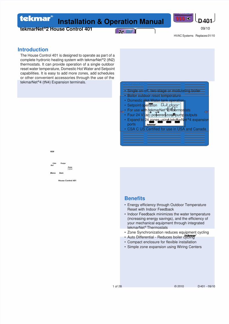
BenefitsEnergy efficiency through Outdoor Temperature
Reset with Indoor Feedback
Indoor Feedback minimizes the water temperature
(increasing energy savings), and the efficiency ofyour mechanical equipment through integrated
tekmarNet ® ThermostatsZone Synchronization reduces equipment cycling
Auto Differential - Reduces boiler cycling
Compact enclosure for flexible installation
Simple zone expansion using Wiring Centers
•
•
•
•
•
•
The House Control 401 is designed to operate as part of acomplete hydronic heating system with tekmarNet ® 2 (tN2)thermostats. It can provide operation of a single outdoorreset water temperature, Domestic Hot Water and Setpointcapabilities. It is easy to add more zones, add schedules
or other convenient accessories through the use of thetekmarNet ® 4 (tN4) Expansion terminals.
FeaturesSingle on-off, two-stage or modulating boiler
Boiler outdoor reset temperature
Domestic Hot Water tank operation
Setpoint operation
For use with tekmarNet ® 2 Thermostats
Four 24 V (ac) powered zone pump outputsExpand to 24 zones using tekmarNet ® 4 expansionports
CSA C US Certified for use in USA and Canada
•
•
•
•
•
••
•
Introduction
8/8/2019 Tekmar 401 tN2 House Control - Boiler, DHW and Setpoint, Four Zone Pumps
http://slidepdf.com/reader/full/tekmar-401-tn2-house-control-boiler-dhw-and-setpoint-four-zone-pumps 2/28
© 2010 D 401 - 09/10 2 of 28
Table of Contents
Getting Started
Caution
Installation ......................................................................2
Preparation ................................................................ 2Physical Dimensions ................................................. 3Installation Location .................................................. 3
Rough-In Wiring ........................................................ 3Sizing the Transformer .............................................. 4
Control Wiring ........................................................... 4
Sensor Wiring ............................................................ 6Testing the Sensor Wiring ......................................... 8Testing the Control Wiring ......................................... 8Max Heat ................................................................... 9
Applications ..................................................................10
User Interface ...............................................................12
Display......................................................................12Symbols ...................................................................12
Navigating The Display ............................................13Access Levels and Thermostat Lock ........................13Programming and Settings .......................................13
View Menu ...............................................................14
Adjust Menu ........................................................15-16Monitor Menu ...........................................................17
Toolbox Menu ...........................................................18
Sequence of Operation ................................................19
tekmarNet ® System ..................................................19Boiler Temperature Reset Operation ........................19
Domestic Hot Water Tank Operation ....................... 20
Setpoint Operation .................................................. 22Boiler Operation ...................................................... 22Pump Operation .......................................................24
Energy Saving Features ...........................................24
Troubleshooting ............................................................25
Error Messages .................................................. 25-26Frequently Asked Questions .............................. 26-27
Job Record ...............................................................27
Technical Data ..............................................................28
Limited Warranty and Product Return Procedure ........28
Congratulations on the purchase of your new tekmarNet ® House Control!
This manual covers the complete installation, programming and sequence of operation for this control. You will also find
instruction on testing, commissioning, and troubleshooting the control and system that it operates.
Improper installation and operation of this control couldresult in damage to the equipment and possibly evenpersonal injury or death. It is your responsibility to ensure
that this control is safely installed according to all applicablecodes and standards. This electronic control is not intendedfor use as a primary limit control. Other controls that areintended and certified as safety limits must be placed into
the control circuit. Do not attempt to service the control.Refer to qualified personnel for servicing. There are nouser serviceable parts. Attempting to do so voids warrantyand could result in damage to the equipment and possiblyeven personal injury or death.
Installation
The installer must ensure that this control and its wiring areisolated and/or shielded from strong sources of electromagneticnoise. Conversely, this Class B digital apparatus complies
with Part 15 of the FCC Rules and meets all requirements ofthe Canadian Interference-Causing Equipment Regulations.However, if this control does cause harmful interferenceto radio or television reception, which is determined byturning the control off and on, the user is encouraged to try
to correct the interference by re-orientating or relocatingthe receiving antenna, relocating the receiver with respectto this control, and/or connecting the control to a different
circuit from that to which the receiver is connected.
Cet appareil numérique de la classe B respecte toutesles exigences du Règlement sur le matériel brouilleur duCanada.
Radio Frequency Interference
Preparation
Tools Required ------------------------------------------------------------------------------------------------------------------------------------------------------------------------------
tekmar or jeweller screwdriver
Phillips head screwdriver
•
•
Needle-nose Pliers
Wire Stripper
•
•
8/8/2019 Tekmar 401 tN2 House Control - Boiler, DHW and Setpoint, Four Zone Pumps
http://slidepdf.com/reader/full/tekmar-401-tn2-house-control-boiler-dhw-and-setpoint-four-zone-pumps 3/283 of 28 © 2010 D 401 - 09/10
Materials Required ----------------------------------------------------------------------------------------------------------------------------------------------------------------------
(2) #10 x 1” Wood Screws
(3) Wire Nuts
18 AWG LVT Solid Wire (Low Voltage Connections)
•
•
•
14 AWG Solid Wire (Line Voltage Connections)
tekmar 009K (24 V (ac) transformer with 4” x 4” junction box
Cable or Conduit Connectors
•
•
•
Power Required ----------------------------------------------------------------------------------------------------------------------------------------------------------------------------
115 V (ac), 1-phase, 15 A service from circuit breaker
panel
• Power disconnect (optional)•
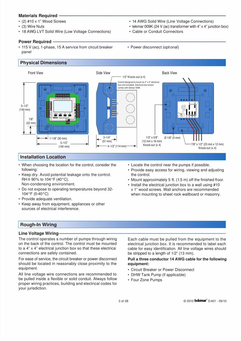
Installation Location
When choosing the location for the control, consider thefollowing:
Keep dry. Avoid potential leakage onto the control.
RH 90% to 104°F (40°C).Non-condensing environment.
Do not expose to operating temperatures beyond 32-104°F (0-40°C)
Provide adequate ventilation.
Keep away from equipment, appliances or othersources of electrical interference.
•
•
•
•
•
Locate the control near the pumps if possible.
Provide easy access for wiring, viewing and adjustingthe control.
Mount approximately 5 ft. (1.5 m) off the finished floor.Install the electrical junction box to a wall using #10x 1” wood screws. Wall anchors are recommended
when mounting to sheet rock wallboard or masonry.
•
•
••
Rough-In Wiring
Line Voltage Wiring----------------------------------------------------------------------------------------------------------------------------------------------------------------------
The control operates a number of pumps through wiringon the back of the control. The control must be mountedto a 4” x 4” electrical junction box so that these electrical
connections are safely contained.
For ease of service, the circuit breaker or power disconnectshould be located in reasonably close proximity to theequipment.
All line voltage wire connections are recommended tobe pulled inside a flexible or solid conduit. Always followproper wiring practices, building and electrical codes foryour jurisdiction.
Physical Dimensions
Each cable must be pulled from the equipment to theelectrical junction box. It is recommended to label eachcable for easy identification. All line voltage wires shouldbe stripped to a length of 1/2” (13 mm).
Pull a three conductor 14 AWG cable for the following
equipment:
Circuit Breaker or Power Disconnect
DHW Tank Pump (if applicable)
Four Zone Pumps
•
•
•
Front View Side View Back View
5–1/2”(140 mm)
5–1/2”(140 mm)
1–1/8” (30 mm)
7/8”(22 mm)
CL
1/2” Knock-out (x 4)
Control designed to mount on 4” x 4” electricalbox (not included). Electrical box showncomes with tekmar 009K
2–1/4”(57 mm)
4–1/2” (114 mm)
Menu
House Control 401
Item
+
C o m
B o i l O u t
D H W
C o m
Zone1
H 8
0 0 6 B
Z on e 2 Z on e 3 Z on e 4t N2 t N2 t N2 t N2 t N2 t N2 t N2 t N2
S e n s o r s - N o P o w e r
C a l l
C a l l
t N 4
C
M o d d c / m A
B o i l E x p .
S e t p o i n t
D H W
RCInput Power
MadeinCanada
Useat least 167°F(75°C)conductors
S t a g e 2
S t a g e 1
4 0 1
Z o n e 4
Z o n e 3
Z o n e 2
Z o n e 1
D H WP u m p P
u m p P o w e r
S t r i p wi r e s 1 / 2 i n c h
( 1 3 mm ) .I n s t a l l e d
wi r e s a r e n o t r e m o v a b l e .
1 2 - 1 8 A W G
Ø 1/8” (3 mm)
7/8” x 1/2” (23 mm x 12 mm)Knock-out (x 4)
1/2” x 5/8”(12 mm x 16 mm)Knock-out (x 4)
8/8/2019 Tekmar 401 tN2 House Control - Boiler, DHW and Setpoint, Four Zone Pumps
http://slidepdf.com/reader/full/tekmar-401-tn2-house-control-boiler-dhw-and-setpoint-four-zone-pumps 4/28
© 2010 D 401 - 09/10 4 of 28
Zone 4
Zone 3
PowerSource
DHW
Zone 2 Zone 1
The control requires an external transformer with 20 VAcapacity or greater. A tekmar Transformer 009 (or 009Kwhich includes a 4” x 4” electrical box) can supply up to 40
VA, and includes an in-line fuse to protect the transformerand control.
Sizing the Transformer
Control Wiring
Line Voltage Wiring----------------------------------------------------------------------------------------------------------------------------------------------------------------------
CAUTION: TURN ALL POWER OFF BEFORE PERFORMING ANY WIRING.
Each cable must be pulled from the equipment to thecontrol’s plastic enclosure. All low voltage wiring connectionsenter the enclosure through conduit knockouts on thesides, or through the square knockouts on the rear. It isrecommended to label each cable for easy identification.
All low voltage wires are to be stripped to a length of 3/8”(9 mm) to ensure proper connection to the control.
Pull two conductor 18 AWG LVT cable, up to 500 feet
(150 m) for the following equipment:tekmarNet ® 2 Thermostats
Boiler Stage 1 T-T
•
•
Boiler Stage 2 T-T (if applicable)
Modulating Boiler 0-10 V (dc) or 4-20 mA (if applicable)
Outdoor Temperature Sensor
Boiler Supply Temperature Sensor
DHW Tank Temperature Sensor (if applicable)
DHW Tank Aquastat (if applicable)
Setpoint Device (if applicable)
Pull three conductor 18 AWG LVT cable for the following
equipment:
tekmarNet ® 4 Accessories (User Switch, Timer)
•
•
•
•
•
•
•
•
Low Voltage Wiring----------------------------------------------------------------------------------------------------------------------------------------------------------------------
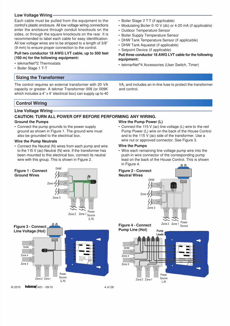
Ground the Pumps
Connect the pump grounds to the power supply
ground as shown in Figure 1. The ground wire mustalso be grounded to the electrical box.
Wire the Pump Neutrals
Connect the Neutral (N) wires from each pump and wireto the 115 V (ac) Neutral (N) wire. If the transformer hasbeen mounted to this electrical box, connect its neutral
wire with this group. This is shown in Figure 2.
•
•
Wire the Pump Power (L)
Connect the 115 V (ac) line voltage (L) wire to the red
Pump Power (L) wire on the back of the House Controland to the 115 V (ac) side of the transformer. Use a
wire nut or approved connector. See Figure 3.
Wire the Pumps
Wire each remaining line voltage pump wire into thepush-in wire connector of the corresponding pump
lead on the back of the House Control. This is shownin Figure 4.
•
•
401
Zone 4 Zone 3
Zone 2
Zone 1DHW Pump
Pump Power
Strip wires 1 /2 inch(13 mm). Installedwires are not removable.12-18 AWG
Zone 4
PowerSource
L,N
DHW
Zone 2 Zone 1
Zone 3
Pump
Leads
Zone 4
Zone 3
PowerSource(L,N)
DHW
Zone 2 Zone 1
Figure 1 - ConnectGround Wires
401
Zone 4 Zone 3
Zone 2
Zone 1DHW Pump
Pump Power
Strip wires 1/ 2 inch(13mm). Installedwires are not removable.12-18 AWG
Zone 3
PowerSource(L,N)
DHW
Zone 2 Zone 1
Zone 4
Figure 2 - ConnectNeutral Wires
Figure 3 - ConnectLine Voltage (Hot)
Figure 4 - Connect
Pump Line (Hot)

8/8/2019 Tekmar 401 tN2 House Control - Boiler, DHW and Setpoint, Four Zone Pumps
http://slidepdf.com/reader/full/tekmar-401-tn2-house-control-boiler-dhw-and-setpoint-four-zone-pumps 5/285 of 28 © 2010 D 401 - 09/10
115 V (ac)
NG L
N
L(red)
(black)
(black)
(black)
(black)
(black)
to pump
grounds
Zone 2
Zone 3
Zone 4
DHW
Zone 1
401
Zone 4 Zone 3
Zone 2
Zone 1DHW Pump
Pump Power
Strip wires 1/2 inch(13 mm). Installed
wires are not removable.12-18 AWG
Rear Line Voltage Wiring Diagram--------------------------------------------------------------------------------------------------------------------------------------
Ensure that the pump wires are neatly tucked inside
the electrical box.
Using 2 of the 4 holes in the back of the enclosure, se-curely fasten it to the electrica junction box with 2 #10
screws as shown in Figure 5.
•
•
Install The Enclosure------------------------------------------------------------------------------------------------------------------------------------------------------------------
Figure 5
External Power SupplyIt is strongly recommended that a transformer with an in-linefuse be used in order to protect the transformer from highcurrents. The tekmar Transformer 009 includes a fuse.
Connect the 24 V (ac) leads from the transformer to theC and R terminals marked “Input Power” on the 401.
tN2 Thermostats
The 401 is designed to operate with tekmarNet ® 2 Thermostats.They provide the heating and cooling control for each zone,and communicate with any other tekmarNet ® device onthe system.
Connect the tN2 terminals from each thermostat to the
corresponding tN2 terminals for each zone on the 401.
tN4 Boiler Expansion Terminals
The 401 uses the Expansion tN4 and C terminals tocommunicate with additional thermostats, setpoint controls,wiring centers, and other tekmarNet ® devices.
Connect the tN4 and C Boil Exp. terminals on the 401
to the corresponding tN4 and C Expansion terminalsof the additional external device.
Domestic Hot Water (DHW) or Setpoint Call
When the control receives a DHW Call or Setpoint Call forheat it will override Outdoor Reset and Indoor Feedback
•
•
•
Low Voltage Wiring----------------------------------------------------------------------------------------------------------------------------------------------------------------------
and operate the boiler to heat the DHW tank or the Setpoinequipment.
To create a DHW call, wire a dry contact OR apply 24V (ac) to the DHW call terminals.
To create a Setpoint call, wire a dry contact OR apply24 V (ac) to the Setpoint call terminals.
Wiring the Boiler
The 401 can operate a single modulating boiler, singleon-off, or a single two-stage on-off boiler.
On/Off Boiler
Connect the Boiler Stage 1 terminals on the 401 to the
T-T (or R-W) terminals on the boiler.If required, connect the Boiler Stage 2 terminals on the
401 to the second stage T-T (or R-W) terminals on theboiler.
Modulating Boiler
Wire the Mod (dc/mA) positive (+) and negative (-) ter-minals on the 401 to the input signal terminals on theboiler. Correct polarity of the wires is important.
In some cases, the modulating boiler also requires
contact closure on the T-T terminals to fire the boiler. Ifrequired, connect the Boiler Stage 1 terminals on the401 to the T-T (or R-W) terminals on the boiler.
•
•
•
•
•
•
8/8/2019 Tekmar 401 tN2 House Control - Boiler, DHW and Setpoint, Four Zone Pumps
http://slidepdf.com/reader/full/tekmar-401-tn2-house-control-boiler-dhw-and-setpoint-four-zone-pumps 6/28
© 2010 D 401 - 09/10 6 of 28
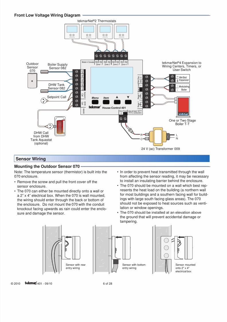
Front Low Voltage Wiring Diagram --------------------------------------------------------------------------------------------------------------------------------------
Sensor Wiring
Note: The temperature sensor (thermistor) is built into the070 enclosure.
Remove the screw and pull the front cover off the
sensor enclosure.
The 070 can either be mounted directly onto a wall or
a 2” x 4” electrical box. When the 070 is wall mounted,the wiring should enter through the back or bottom of
the enclosure. Do not mount the 070 with the conduitknockout facing upwards as rain could enter the enclo-
sure and damage the sensor.
•
•
In order to prevent heat transmitted through the wall
from affecting the sensor reading, it may be necessaryto install an insulating barrier behind the enclosure.
The 070 should be mounted on a wall which best rep-resents the heat load on the building (a northern wall
for most buildings and a southern facing wall for build-ings with large south facing glass areas). The 070
should not be exposed to heat sources such as venti-lation or window openings.
The 070 should be installed at an elevation abovethe ground that will prevent accidental damage or
tampering.
•
•
•
Mounting the Outdoor Sensor 070----------------------------------------------------------------------------------------------------------------------------------------
Sensor with bottomentry wiring
Sensor with rearentry wiring
Sensor mountedonto 2" x 4"electrical box
R
C
L
N
ExpansiontN4 Boil
C
t N 4
ModulatingBoiler
—
+
2
1
Menu
House Control 401
Item
+
C o m
B o i l O u t
D H W
C o m
Zone 1
H 8 0 0 6 B
Zone 2 Zone 3 Zone 4tN2 tN2 tN2 tN2 tN2 tN2 tN2 tN2
S e n s o r s - N o P o w e r
C a l l
C a l l
t N 4
C
M o d d c / m A
B o i l E x p .
S e t p o i n t
D H W
RC
Input Power
Made in Canada
Use at least 167°F
(75°C) conductors
S t a g e 2
S t a g e 1
24 V (ac) Transformer 009
DHW Callfrom DHW
Tank Aquastat(optional)
Setpoint Call
OutdoorSensor
070
Boiler SupplySensor 082
DHW TankSensor 082
One or Two StageBoiler T-T
tekmarNet ® 2 Thermostats
tekmarNet ® 4 Expansion toWiring Centers, Timers, or
User Switch
8/8/2019 Tekmar 401 tN2 House Control - Boiler, DHW and Setpoint, Four Zone Pumps
http://slidepdf.com/reader/full/tekmar-401-tn2-house-control-boiler-dhw-and-setpoint-four-zone-pumps 7/287 of 28 © 2010 D 401 - 09/10
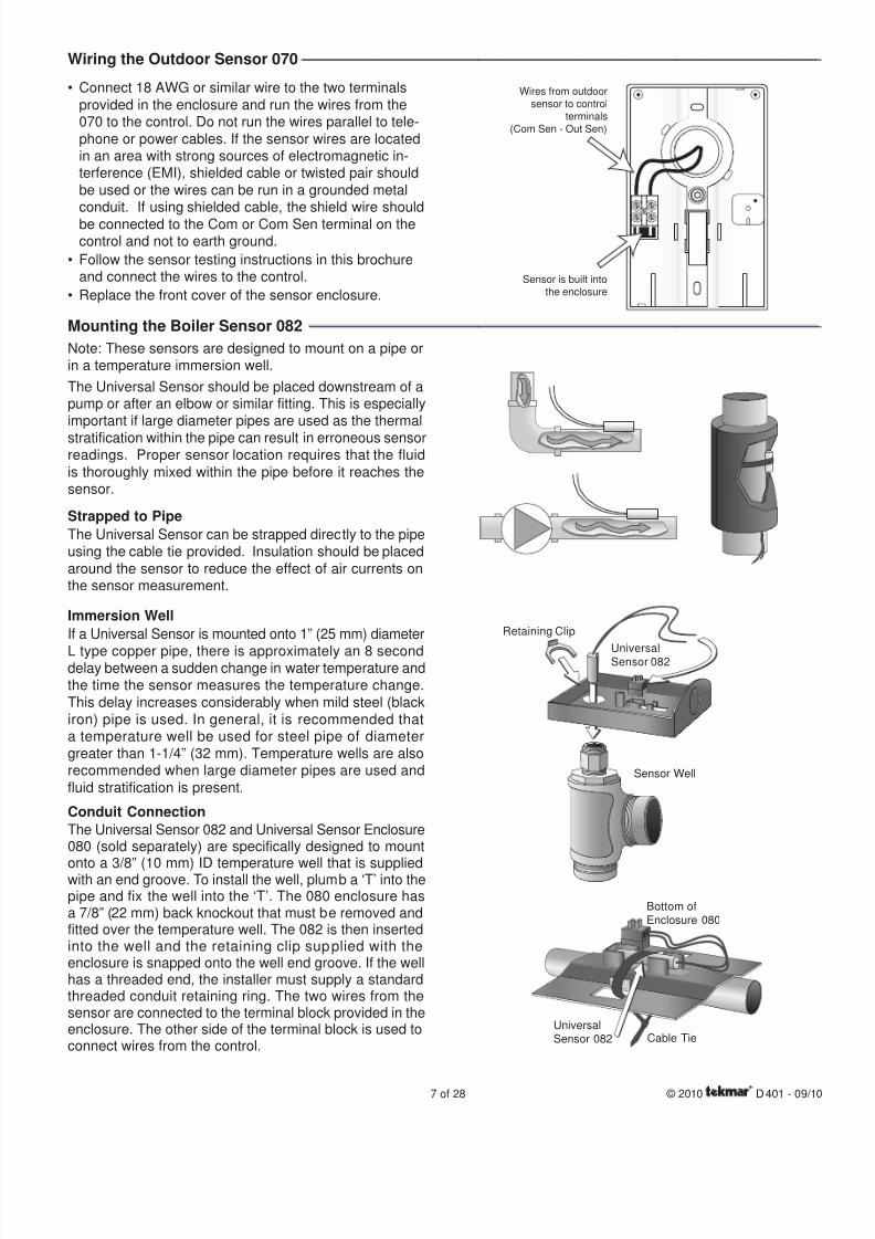
Connect 18 AWG or similar wire to the two terminals
provided in the enclosure and run the wires from the070 to the control. Do not run the wires parallel to tele-
phone or power cables. If the sensor wires are locatedin an area with strong sources of electromagnetic in-terference (EMI), shielded cable or twisted pair should
be used or the wires can be run in a grounded metalconduit. If using shielded cable, the shield wire should
be connected to the Com or Com Sen terminal on thecontrol and not to earth ground.
Follow the sensor testing instructions in this brochureand connect the wires to the control.
Replace the front cover of the sensor enclosure.
•
•
•
Wiring the Outdoor Sensor 070----------------------------------------------------------------------------------------------------------------------------------------------
Wires from outdoor
sensor to control
terminals
(Com Sen - Out Sen)
Sensor is built into
the enclosure
Mounting the Boiler Sensor 082 --------------------------------------------------------------------------------------------------------------------------------------------
Note: These sensors are designed to mount on a pipe orin a temperature immersion well.
The Universal Sensor should be placed downstream of apump or after an elbow or similar fitting. This is especiallyimportant if large diameter pipes are used as the thermal
stratification within the pipe can result in erroneous sensorreadings. Proper sensor location requires that the fluidis thoroughly mixed within the pipe before it reaches thesensor.
Strapped to Pipe
The Universal Sensor can be strapped directly to the pipeusing the cable tie provided. Insulation should be placed
around the sensor to reduce the effect of air currents onthe sensor measurement.
Immersion Well
If a Universal Sensor is mounted onto 1” (25 mm) diameter
L type copper pipe, there is approximately an 8 seconddelay between a sudden change in water temperature andthe time the sensor measures the temperature change.This delay increases considerably when mild steel (black
iron) pipe is used. In general, it is recommended thata temperature well be used for steel pipe of diametergreater than 1-1/4” (32 mm). Temperature wells are alsorecommended when large diameter pipes are used andfluid stratification is present.
Conduit Connection
The Universal Sensor 082 and Universal Sensor Enclosure080 (sold separately) are specifically designed to mount
onto a 3/8” (10 mm) ID temperature well that is suppliedwith an end groove. To install the well, plumb a ‘T’ into thepipe and fix the well into the ‘T’. The 080 enclosure hasa 7/8” (22 mm) back knockout that must be removed andfitted over the temperature well. The 082 is then insertedinto the well and the retaining clip supplied with theenclosure is snapped onto the well end groove. If the wellhas a threaded end, the installer must supply a standardthreaded conduit retaining ring. The two wires from thesensor are connected to the terminal block provided in theenclosure. The other side of the terminal block is used toconnect wires from the control.
Bottom ofEnclosure 080
UniversalSensor 082 Cable Tie
Sensor Well
Retaining Clip
UniversalSensor 082
8/8/2019 Tekmar 401 tN2 House Control - Boiler, DHW and Setpoint, Four Zone Pumps
http://slidepdf.com/reader/full/tekmar-401-tn2-house-control-boiler-dhw-and-setpoint-four-zone-pumps 8/28
© 2010 D 401 - 09/10 8 of 28
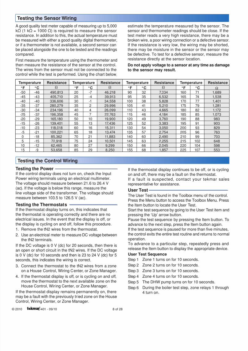
A good quality test meter capable of measuring up to 5,000kΩ (1 kΩ = 1000 Ω) is required to measure the sensorresistance. In addition to this, the actual temperature mustbe measured with either a good quality digital thermometer,or if a thermometer is not available, a second sensor canbe placed alongside the one to be tested and the readingscompared.
First measure the temperature using the thermometer andthen measure the resistance of the sensor at the control.The wires from the sensor must not be connected to thecontrol while the test is performed. Using the chart below,
estimate the temperature measured by the sensor. Thesensor and thermometer readings should be close. If thetest meter reads a very high resistance, there may be abroken wire, a poor wiring connection or a defective sensor.If the resistance is very low, the wiring may be shorted,there may be moisture in the sensor or the sensor maybe defective. To test for a defective sensor, measure theresistance directly at the sensor location.
Do not apply voltage to a sensor at any time as damage
to the sensor may result.
Testing the Sensor Wiring
Temperature Resistance Temperature Resistance Temperature Resistance Temperature Resistance
°F °C °F °C °F °C °F °C-50 -46 490,813 20 -7 46,218 90 32 7,334 160 71 1,689
-45 -43 405,710 25 -4 39,913 95 35 6,532 165 74 1,538
-40 -40 336,606 30 -1 34,558 100 38 5,828 170 77 1,401
-35 -37 280,279 35 2 29,996 105 41 5,210 175 79 1,281
-30 -34 234,196 40 4 26,099 110 43 4,665 180 82 1,172
-25 -32 196,358 45 7 22,763 115 46 4,184 185 85 1,073
-20 -29 165,180 50 10 19,900 120 49 3,760 190 88 983
-15 -26 139,401 55 13 17,436 125 52 3,383 195 91 903-10 -23 118,018 60 16 15,311 130 54 3,050 200 93 829
-5 -21 100,221 65 18 13,474 135 57 2,754 205 96 763
0 -18 85,362 70 21 11,883 140 60 2,490 210 99 703
5 -15 72,918 75 24 10,501 145 63 2,255 215 102 648
10 -12 62,465 80 27 9,299 150 66 2,045 220 104 598
15 -9 53,658 85 29 8,250 155 68 1,857 225 107 553
Testing the Control Wiring
Testing the Power ------------------------------------------------------------
If the control display does not turn on, check the InputPower wiring terminals using an electrical multimeter.
The voltage should measure between 21.6 to 26.4 V(ac). If the voltage is below this range, measure the
line voltage side of the transformer. The voltage shouldmeasure between 103.5 to 126.5 V (ac).
Testing the Thermostats ----------------------------------------------
If the thermostat display turns on, this indicates that
the thermostat is operating correctly and there are noelectrical issues. In the event that the display is off, or
the display is cycling on and off, follow this procedure.
1. Remove the tN2 wires from the thermostat.
2. Use an electrical meter to measure DC voltage betweenthe tN2 terminals.
If the DC voltage is 0 V (dc) for 20 seconds, then there isan open or short circuit in the tN2 wires. If the DC voltageis 0 V (dc) for 10 seconds and then is 23 to 24 V (dc) for 5seconds, this indicates the wiring is correct.
3. Connect the thermostat to the tN2 wires from a zoneon a House Control, Wiring Center, or Zone Manager.
4. If the thermostat display is off, or is cycling on and off,move the thermostat to the next available zone on theHouse Control, Wiring Center, or Zone Manager.
If the thermostat display remains permanently on, theremay be a fault with the previously tried zone on the HouseControl, Wiring Center, or Zone Manager.
If the thermostat display continues to be off, or is cyclingon and off, there may be a fault on the thermostat.If a fault is suspected, contact your tekmar sales
representative for assistance.User Test----------------------------------------------------------------------------
The User Test is found in the Toolbox menu of the control.
Press the Menu button to access the Toolbox Menu. Pressthe Item button to locate the User Test.
Start the test sequence by going to the User Test item andpressing the ‘Up’ arrow button.Pause the test sequence by pressing the Item button. Toadvance to the next step, press the Item button again.
If the test sequence is paused for more than five minutes,
the control exits the entire test routine and returns to normaloperation.To advance to a particular step, repeatedly press andrelease the Item button to display the appropriate device.
User Test Sequence
Step 1 Zone 1 turns on for 10 seconds.
Step 2 Zone 2 turns on for 10 seconds.
Step 3 Zone 3 turns on for 10 seconds.
Step 4 Zone 4 turns on for 10 seconds.
Step 5 The DHW pump turns on for 10 seconds.
Step 6 During the boiler test step, zone relays 1 through
4 turn on.
8/8/2019 Tekmar 401 tN2 House Control - Boiler, DHW and Setpoint, Four Zone Pumps
http://slidepdf.com/reader/full/tekmar-401-tn2-house-control-boiler-dhw-and-setpoint-four-zone-pumps 9/289 of 28 © 2010 D 401 - 09/10
If the Boil Type is 1 Stage, the boiler stage 1 relay is
closed for 10 seconds and then opened.
If the Boil Type is 2 Stage, the boiler stage 1 relay is
closed for 10 seconds, then the boiler stage 2 relay isclosed for 10 seconds and then both relays are opened.
If Boiler Type is modulating 0 - 10, the boiler stage1 relay is closed for 10 seconds and the modulating
output operates at 50 % [5 V (dc)].
If Boiler Type is modulating 4 - 20, the boiler stage
1 relay is closed for 10 seconds and the modulatingoutput operates at 50 % (12 mA).
Step 7 Control returns to normal operation.
Testing the Zone Output --------------------------------------------
Activate the User Test sequence and pause at Step 1 bypressing the Item button once Zone 1 turns on. Using anelectrical meter, measure the voltage between the zone1 pump and terminals. The voltage should measurebetween 103.5 V (ac) and 126.5 V (ac). Repeat for Zones2, 3, and 4.
Testing the DHW Pump ----------------------------------------------
Activate the User Test sequence and pause at Step 5 bypressing the Item button once the DHW pump turns on.Using an electrical meter, measure the voltage betweenthe DHW pump and a neutral. The voltage should measurebetween 103.5 V (ac) and 126.5 V (ac).
Testing the Boiler Stage 1 Contact--------------------------
Activate the User Test sequence and pause at Step 6 bypressing the Item button once the boiler stage 1 turns on.
Using an electrical meter, measure for continuity over theboiler stage 1 terminals.
•
•
•
•
Testing the Boiler Stage 2 Contact--------------------------
This test applies for 2 stage on-off boilers only.Activate the User Test sequence and pause at Step 6 bypressing the Item button once the boiler stage 2 turns on
Using an electrical meter, measure for continuity over theboiler stage 2 terminals.
Testing the Boiler Modulating Output--------------------
This test applies for modulating boilers only.
Active the User Test sequence and pause at Step 6 by
pressing the Item button once the boiler stage 1 turns onUsing an electrical meter, measure for either a 5 V (dc) o
12 mA signal. The Boil Type setting selects whether thesignal is V (dc) or mA.
Testing the DHW Call----------------------------------------------------
Remove all wires from the DHW Call terminals. The controdisplay should show no DHW Call. Reconnect wires. Thenapply either a short circuit or 24 V (ac) over the DHW Cal
terminals. The control should now show a DHW Call.
Testing the Setpoint Call --------------------------------------------
Remove all wires from the Setpoint Call terminals. The
control display should show no Setpoint Call. Reconnecwires. Then apply either a short circuit or 24 V (ac) ovethe Setpoint Call terminals. The control should now showa Setpoint Call.
The control has a function called Max Heat. In this mode,
the control turns on and operates the system up to themaximum set temperatures as long as there is a call forheat. Use this mode to run the circulators during systemstart-up and commissioning, and purging air from the piping.This function is useful when drying sheet rock and paintin the building.
To enable Max Heat, enter the Toolbox Menu and find MaxHeat. Use the up arrow to select ‘On’.
When a space heating call is present, the boiler will
run to maintain a target of Boil Design + 10°F (+ 6°C).(One can purge the system using this test and leave
the boiler un-powered. This will prevent heat from en-tering the system during the purge.)
•
When a DHW Call or Setpoint Call is present, the
boiler will operate at the DHW exchange or Setpointtemperature settings.
WWSD and DHW Priority is disabled during Max Heatmode.
When Max Heat is on the display will show ‘Max HeatTest’.
Max Heat will automatically turn off after 24 hours.
To Cancel Max Heat, go to Max Heat in the Toolbox menuand use the down arrow to select ‘Off’.
•
•
•
•
Max Heat
8/8/2019 Tekmar 401 tN2 House Control - Boiler, DHW and Setpoint, Four Zone Pumps
http://slidepdf.com/reader/full/tekmar-401-tn2-house-control-boiler-dhw-and-setpoint-four-zone-pumps 10/28
© 2010 D 401 - 09/10 10 of 28
Applications
R
C
L
N
ExpansiontN4 Boil
C
t N 4
1
Menu
House Control 401
Item
+
C o m
B o i l O u t
D H W
C o m
Zone 1
H 8 0 0 6 B
Zone 2 Zone 3 Zone 4tN2 tN2 tN2 tN2 tN2 tN2 tN2 tN2
S e n s o r s - N o P o w e r
C a l l
C a l l
t N 4
C
M o d d c / m
A
B o i l E x p .
S e t p o i n t
D H W
RCInput Power
Made in Canada
Use at least 167°F(75°C) conductors
S t a g e 2
S t a g e 1
115 V (ac)
NG L
N
L(red)
(black)
(black)
(black)
(black)
(black)
to pumpgrounds
Back ofHouse Control 401
401
Zone 4 Zone 3
Zone 2
Zone 1DHW Pump
Pump Power
Strip wires 1/2 inch(13 mm). Installedwires are not removable.12-18 AWG
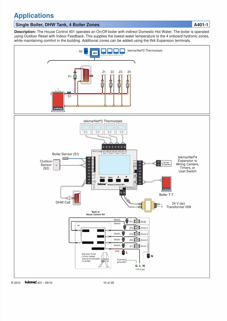
Description: The House Control 401 operates an On/Off boiler with indirect Domestic Hot Water. The boiler is operated
using Outdoor Reset with Indoor Feedback. This supplies the lowest water temperature to the 4 onboard hydronic zones,while maintaining comfort in the building. Additional zones can be added using the tN4 Expansion terminals.
Single Boiler, DHW Tank, 4 Boiler Zones A401-1
401070S2
S1
OutdoorSensor
(S2)
tekmarNet ® 2 Thermostats
Boiler T-T
24 V (ac)Transformer 009
Boiler Sensor (S1)
DHW Call
tekmarNet ® 4Expansion to
Wiring Centers,
Timers, orUser Switch
tekmarNet ® 2 Thermostats
P1
Z1 Z2 Z3 Z4
DHW
Zone 4
Zone 3
Zone 2
Zone 1
(P1)
(Z4)
(Z3)
(Z2)
(Z1)
8/8/2019 Tekmar 401 tN2 House Control - Boiler, DHW and Setpoint, Four Zone Pumps
http://slidepdf.com/reader/full/tekmar-401-tn2-house-control-boiler-dhw-and-setpoint-four-zone-pumps 11/2811 of 28 © 2010 D 401 - 09/10
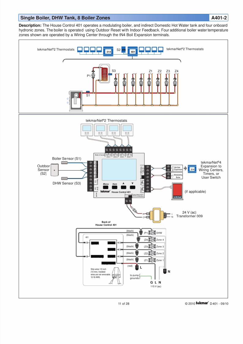
Description: The House Control 401 operates a modulating boiler, and indirect Domestic Hot Water tank and four onboard
hydronic zones. The boiler is operated using Outdoor Reset with Indoor Feedback. Four additional boiler water temperaturezones shown are operated by a Wiring Center through the tN4 Boil Expansion terminals.
R
C
L
N
ExpansiontN4 Boil
C
t N 4
ModulatingBoiler
—
+
1
314
115 V (ac)
NG L
N
L(red)
(black)
(black)
(black)
(black)
(black)
to pumpgrounds
Back ofHouse Control 401
401
Zone 4 Zone 3
Zone 2
Zone 1DHW Pump
Pump Power
Strip wires 1/2 inch
(13 mm). Installed
wires are not removable.
12-18 AWG
Menu
House Control 401
Item
+
C o m
B o i l O u t
D H W
C o m
Zone 1
H 8 0 0 6 B
Zone 2 Zone 3 Zone 4tN2 tN2 tN2 tN2 tN2 tN2 tN2 tN2
S e n s o r s - N o P o w e r
C a l l
C a l l
t N 4
C
M o d d c / m A
B o i l E x p .
S e t p o i n t
D H W
RC
Input Power
Made in Canada
Use at least 167°F(75°C) conductors
S t a g e 2
S t a g e 1
401070
314
Single Boiler, DHW Tank, 8 Boiler Zones A401-2
S2
S1
S3
24 V (ac)Transformer 009
DHW Sensor (S3)
Boiler Sensor (S1)
tekmarNet ® 2 Thermostats
OutdoorSensor
(S2)
tekmarNet ® 4Expansion to
Wiring Centers,Timers, or
User Switch
tekmarNet ® 2 ThermostatstekmarNet ® 2 Thermostats
(if applicable)
P1
Z1 Z2 Z3 Z4
DHW
Zone 4
Zone 3
Zone 2
Zone 1
(P1)
(Z4)
(Z3)
(Z2)
(Z1)
8/8/2019 Tekmar 401 tN2 House Control - Boiler, DHW and Setpoint, Four Zone Pumps
http://slidepdf.com/reader/full/tekmar-401-tn2-house-control-boiler-dhw-and-setpoint-four-zone-pumps 12/28
© 2010 D 401 - 09/10 12 of 28
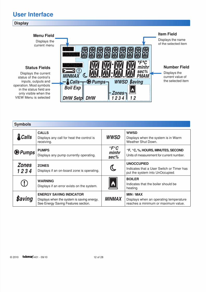
Calls CALLS
Displays any call for heat the control isreceiving.
Pumps PUMPS
Displays any pump currently operating.
Zones 1 2 3 4
ZONES
Displays if an on-board zone is operating.
WARNING
Displays if an error exists on the system.
Saving ENERGY SAVING INDICATOR
Displays when the system is saving energy.
See Energy Saving Features section.
WWSD WWSD
Displays when the system is in WarmWeather Shut Down.
°F°C
minhr sec%
°F, °C, %, HOURS, MINUTES, SECOND
Units of measurement for current number.
UNOCCUPIED
Indicates that a User Switch or Timer hasput the system into UnOccupied.
BOILER
Indicates that the boiler should beheating.
MAX MIN MIN / MAX
Displays when an operating temperature
reaches a minimum or maximum value.
Symbols
Display
MONITOR
VIEWADJUST
MAX MIN
Boil Exp
DHW Setp Zones
DHW 1 2 3 4 1 2
AM
min sec
hr
PM Calls Pumps WWSD Saving
Item Field
Displays the name
of the selected item
Number Field
Displays thecurrent value of
the selected item
Status Fields
Displays the currentstatus of the control’s
inputs, outputs andoperation. Most symbols
in the status field areonly visible when the
VIEW Menu is selected
Menu Field
Displays thecurrent menu
User Interface
8/8/2019 Tekmar 401 tN2 House Control - Boiler, DHW and Setpoint, Four Zone Pumps
http://slidepdf.com/reader/full/tekmar-401-tn2-house-control-boiler-dhw-and-setpoint-four-zone-pumps 13/2813 of 28 © 2010 D 401 - 09/10
Navigating The Display
Menu Button ----------------------------------------------------------------------------------------------------------------------------------------------------------------------------------
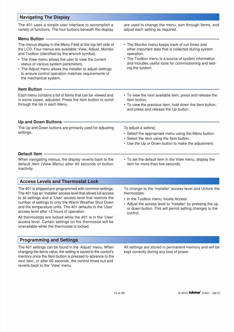
The 401 uses a simple user interface to accomplish avariety of functions. The four buttons beneath the display
are used to change the menu, sort through Items, andadjust each setting as required.
The menus display in the Menu Field at the top left side ofthe LCD. Four menus are available: View, Adjust, Monitorand Toolbox (identified by the wrench symbol).
The View menu allows the user to view the currentstatus of various system parameters.
The Adjust menu allows the installer to adjust settings
to ensure control operation matches requirements ofthe mechanical system.
•
•
The Monitor menu keeps track of run times andother important data that is collected during systemoperation.
The Toolbox menu is a source of system informationand includes useful tools for commissioning and test-ing the system.
•
•
Item Button ------------------------------------------------------------------------------------------------------------------------------------------------------------------------------------
Each menu contains a list of Items that can be viewed and,in some cases, adjusted. Press the item button to scrollthrough the list in each Menu.
To view the next available item, press and release theItem button.
To view the previous item, hold down the Item button,and press and release the Up button.
•
•
Up and Down Buttons ----------------------------------------------------------------------------------------------------------------------------------------------------------------
The Up and Down buttons are primarily used for adjustingsettings.
To adjust a setting:
Select the appropriate menu using the Menu button.
Select the item using the Item button.
Use the Up or Down button to make the adjustment.
•
•
•
Default Item ------------------------------------------------------------------------------------------------------------------------------------------------------------------------------------
When navigating menus, the display reverts back to thedefault item (View Menu) after 60 seconds of buttoninactivity.
To set the default item in the View menu, display theitem for more than five seconds.
•
Access Levels and Thermostat Lock
The 401 is shipped pre-programmed with common settings.The 401 has an ‘Installer’ access level that allows full accessto all settings and a ‘User’ access level that restricts thenumber of settings to only the Warm Weather Shut Down
and the temperature units. The 401 defaults to the ‘User’access level after 12 hours of operation.
All thermostats are locked while the 401 is in the ‘User’access level. Certain settings on the thermostat will beunavailable while the thermostat is locked.
To change to the ‘Installer’ access level and Unlock thethermostats:
In the Toolbox menu, locate Access
Adjust the access level to ‘Installer’ by pressing the upor down button. This will permit setting changes to the
control.
•
•
Programming and Settings
The 401 settings can be found in the ‘Adjust’ menu. Whenchanging the items value, the setting is saved to the control’smemory once the Item button is pressed to advance to thenext item, or after 60 seconds, the control times out andreverts back to the ‘View’ menu.
All settings are stored in permanent memory and will bekept correctly during any loss of power.
8/8/2019 Tekmar 401 tN2 House Control - Boiler, DHW and Setpoint, Four Zone Pumps
http://slidepdf.com/reader/full/tekmar-401-tn2-house-control-boiler-dhw-and-setpoint-four-zone-pumps 14/28
© 2010 D 401 - 09/10 14 of 28
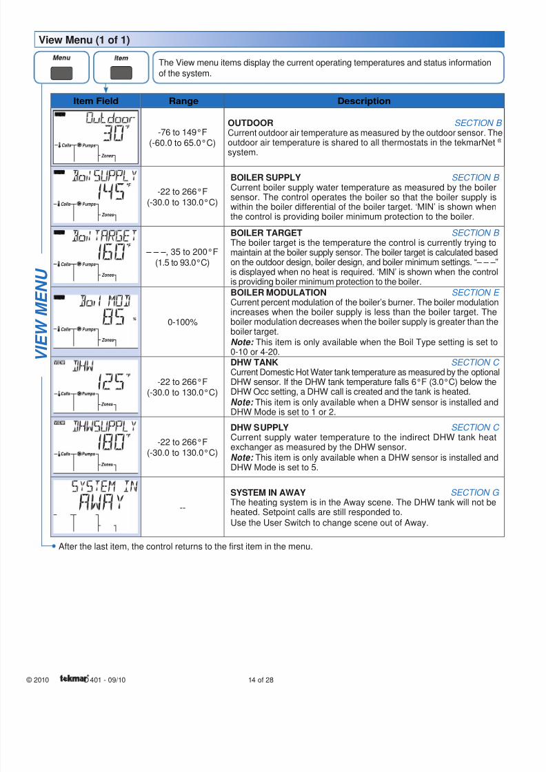
Item Field Range Description
VIEW
Zones
Calls Pumps -76 to 149°F(-60.0 to 65.0°C)
OUTDOOR SECTION B
Current outdoor air temperature as measured by the outdoor sensor. Theoutdoor air temperature is shared to all thermostats in the tekmarNet ® system.
VIEW
Zones
Calls Pumps
-22 to 266°F
(-30.0 to 130.0°C)
BOILER SUPPLY SECTION B Current boiler supply water temperature as measured by the boilersensor. The control operates the boiler so that the boiler supply iswithin the boiler differential of the boiler target. ‘MIN’ is shown whenthe control is providing boiler minimum protection to the boiler.
VIEW
Zones
Calls Pumps
– – –, 35 to 200°F
(1.5 to 93.0°C)
BOILER TARGET SECTION B The boiler target is the temperature the control is currently trying tomaintain at the boiler supply sensor. The boiler target is calculated basedon the outdoor design, boiler design, and boiler minimum settings. “– – –”
is displayed when no heat is required. ‘MIN’ is shown when the controlis providing boiler minimum protection to the boiler.
VIEW
Zones
Calls Pumps 0-100%
BOILER MODULATION SECTION E Current percent modulation of the boiler’s burner. The boiler modulationincreases when the boiler supply is less than the boiler target. Theboiler modulation decreases when the boiler supply is greater than theboiler target.Note: This item is only available when the Boil Type setting is set to0-10 or 4-20.
-22 to 266°F(-30.0 to 130.0°C)
DHW TANK SECTION C Current Domestic Hot Water tank temperature as measured by the optionalDHW sensor. If the DHW tank temperature falls 6°F (3.0°C) below theDHW Occ setting, a DHW call is created and the tank is heated.
Note: This item is only available when a DHW sensor is installed andDHW Mode is set to 1 or 2.
-22 to 266°F(-30.0 to 130.0°C)
DHW SUPPLY SECTION C Current supply water temperature to the indirect DHW tank heatexchanger as measured by the DHW sensor.Note: This item is only available when a DHW sensor is installed andDHW Mode is set to 5.
--
SYSTEM IN AWAY SECTION G The heating system is in the Away scene. The DHW tank will not beheated. Setpoint calls are still responded to.
Use the User Switch to change scene out of Away.
V I E W M E N U
View Menu (1 of 1)
The View menu items display the current operating temperatures and status information
of the system.
After the last item, the control returns to the first item in the menu.
8/8/2019 Tekmar 401 tN2 House Control - Boiler, DHW and Setpoint, Four Zone Pumps
http://slidepdf.com/reader/full/tekmar-401-tn2-house-control-boiler-dhw-and-setpoint-four-zone-pumps 15/2815 of 28 © 2010 D 401 - 09/10
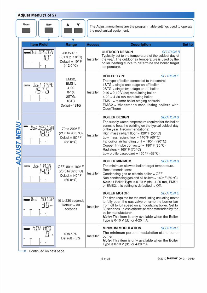
Item Field Range Access Description Set to
ADJUST -60 to 45°F(-51.0 to 7.0°C)
Default = 10°F(-12.0°C)
Installer
OUTDOOR DESIGN SECTION B Typically set to the temperature of the coldest day ofthe year. The outdoor air temperature is used by theboiler heating curve to determine the boiler targettemperature.
EMS2,
EMS1,
4-20
0-10,
2STG,
1STGDefault = 1STG
Installer
BOILER TYPE SECTION E
The type of boiler connected to the control.1STG = single one-stage on-off boiler2STG = single two-stage on-off boiler
0-10 = 0-10 V (dc) modulating boiler4-20 = 4-20 mA modulating boiler
EMS1 = tekmar boiler staging controlsEMS2 = Viessmann modulating boilers withOpenTherm
VIEW
70 to 200°F
(21.0 to 93.5°C)
Default = 180°F
(82.0°C)
Installer
BOILER DESIGN SECTION B
The supply water temperature required for the boilerzones to heat the building on the typical coldest dayof the year. Recommendations:High mass radiant floor = 120°F (50°C)
Low mass radiant floor = 140°F (60°C)Fancoil or air handling unit = 190°F (90°C)Copper fin-tube convector = 180°F (80°C)
Radiators = 160°F (70°C)
Low profile baseboard = 150°F (65°C)
OFF, 80 to 180°F
(26.5 to 82.0°C)
Default = 140°F
(60.0°C)
Installer
BOILER MINIMUM SECTION B
The minimum allowed boiler target temperature.Recommendations:Condensing gas or electric boiler = OFF
Non-condensing gas and oil boilers = 140°F (60°C)Note: If Boiler Type is 0-10 V (dc), 4-20 mA, EMS1or EMS2, this setting is defaulted to Off.
ADJUST
sec
10 to 230 seconds
Default = 30seconds
Installer
BOILER MOTOR SECTION E
The time required for the modulating actuating motorto fully open the gas valve or ramp the burner fan
from off to full speed on a modulating boiler. Set to30 seconds unless otherwise recommended by theboiler manufacturer.Note: This item is only available when the BoilerType is 0-10 V (dc) or 4-20 mA.
ADJUST
0 to 50%
Default = 0%Installer
MINIMUM MODULATION SECTION E
The minimum percent modulation of the boilerburner.Note: This item is only available when the BoilerType is 0-10 V (dc) or 4-20 mA.
A D J U S T M E N U
Adjust Menu (1 of 2)
The Adjust menu items are the programmable settings used to operatethe mechanical equipment.
Continued on next page.
8/8/2019 Tekmar 401 tN2 House Control - Boiler, DHW and Setpoint, Four Zone Pumps
http://slidepdf.com/reader/full/tekmar-401-tn2-house-control-boiler-dhw-and-setpoint-four-zone-pumps 16/28
© 2010 D 401 - 09/10 16 of 28
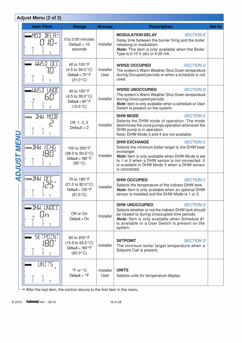
Item Field Range Access Description Set to
ADJUST
sec
0 to 3:00 minutes
Default = 10seconds
Installer
MODULATION DELAY SECTION E
Delay time between the burner firing and the boilerreleasing to modulation.
Note: This item is only available when the BoilerType is 0-10 V (dc) or 4-20 mA.
ADJUST 40 to 100°F
(4.5 to 38.0°C)
Default = 70°F
(21.0°C)
Installer
User
WWSD OCCUPIED SECTION G
The system’s Warm Weather Shut Down temperatureduring Occupied periods or when a schedule is notused.
ADJUST 40 to 100°F
(4.5 to 38.0°C)
Default = 60°F
(15.5°C)
Installer
WWSD UNOCCUPIED SECTION G
The system’s Warm Weather Shut Down temperatureduring Unoccupied periods.Note: Item is only available when a schedule or UserSwitch is present on the system.
Off, 1, 2, 5
Default = 2Installer
DHW MODE SECTION C
Selects the DHW mode of operation. The modedetermines the zone pumps operation whenever theDHW pump is in operation.
Note: DHW Mode 3 and 4 are not available.
100 to 200°F
(38.0 to 93.5°C)
Default = 180°F
(82°C)
Installer
DHW EXCHANGE SECTION C
Selects the minimum boiler target to the DHW heatexchanger.Note: Item is only available when DHW Mode is setto 1 or 2 when a DHW sensor is not connected. Itis available in DHW Mode 5 when a DHW sensoris connected.
70 to 180°F(21.0 to 82.0°C)
Default = 125°F
(51.5°C)
Installer
DHW OCCUPIED SECTION C Selects the temperature of the indirect DHW tank.
Note: Item is only available when an optional DHWsensor is installed and the DHW Mode is 1 or 2.
ADJUST
Off or On
Default = OnInstaller
DHW UNOCCUPIED SECTION G
Selects whether or not the indirect DHW tank shouldbe heated to during Unoccupied time periods.Note: Item is only available when Schedule #1is available or a User Switch is present on thesystem.
ADJUST 60 to 200°F
(15.5 to 93.5°C)
Default = 180°F
(82.0°C)
InstallerSETPOINT SECTION D The minimum boiler target temperature when aSetpoint Call is present.
ADJUST
°F or °C
Default = °F
Installer
User
UNITS
Selects units for temperature display.
Adjust Menu (2 of 2)
A
D J U S T M E N U
After the last item, the control returns to the first item in the menu.
8/8/2019 Tekmar 401 tN2 House Control - Boiler, DHW and Setpoint, Four Zone Pumps
http://slidepdf.com/reader/full/tekmar-401-tn2-house-control-boiler-dhw-and-setpoint-four-zone-pumps 17/2817 of 28 © 2010 D 401 - 09/10
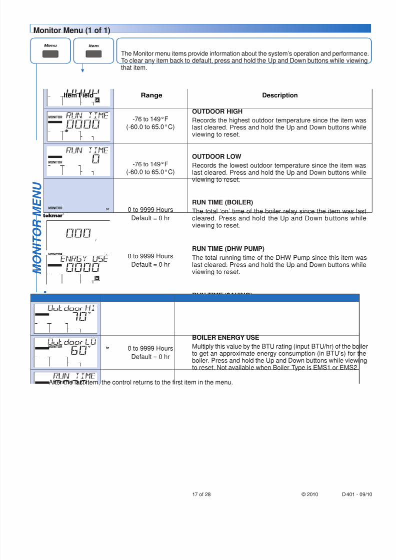
Item Field Range Description
MONITOR -76 to 149°F
(-60.0 to 65.0°C)
OUTDOOR HIGH
Records the highest outdoor temperature since the item waslast cleared. Press and hold the Up and Down buttons whileviewing to reset.
MONITOR -76 to 149°F(-60.0 to 65.0°C)
OUTDOOR LOW
Records the lowest outdoor temperature since the item waslast cleared. Press and hold the Up and Down buttons whileviewing to reset.
MONITOR hr 0 to 9999 Hours
Default = 0 hr
RUN TIME (BOILER)
The total ‘on’ time of the boiler relay since the item was lastcleared. Press and hold the Up and Down buttons whileviewing to reset.
MONITOR hr
DHW
Pumps
0 to 9999 Hours
Default = 0 hr
RUN TIME (DHW PUMP)
The total running time of the DHW Pump since this item waslast cleared. Press and hold the Up and Down buttons whileviewing to reset.
MONITOR hr
Saving
0 to 9999 Hours
Default = 0 hr
RUN TIME ($AVING)Maintains a record of the total length of time the $aving iconhas been active. Press and hold the Up and Down but tonswhile viewing to reset.
MONITOR hr 0 to 9999 Hours
Default = 0 hr
BOILER ENERGY USE
Multiply this value by the BTU rating (input BTU/hr) of the boilerto get an approximate energy consumption (in BTU’s) for theboiler. Press and hold the Up and Down buttons while viewingto reset. Not available when Boiler Type is EMS1 or EMS2.
M O N I T O R M E N
U
After the last item, the control returns to the first item in the menu.
The Monitor menu items provide information about the system’s operation and performance.To clear any item back to default, press and hold the Up and Down buttons while viewingthat item.
Monitor Menu (1 of 1)
8/8/2019 Tekmar 401 tN2 House Control - Boiler, DHW and Setpoint, Four Zone Pumps
http://slidepdf.com/reader/full/tekmar-401-tn2-house-control-boiler-dhw-and-setpoint-four-zone-pumps 18/28
© 2010 D 401 - 09/10 18 of 28
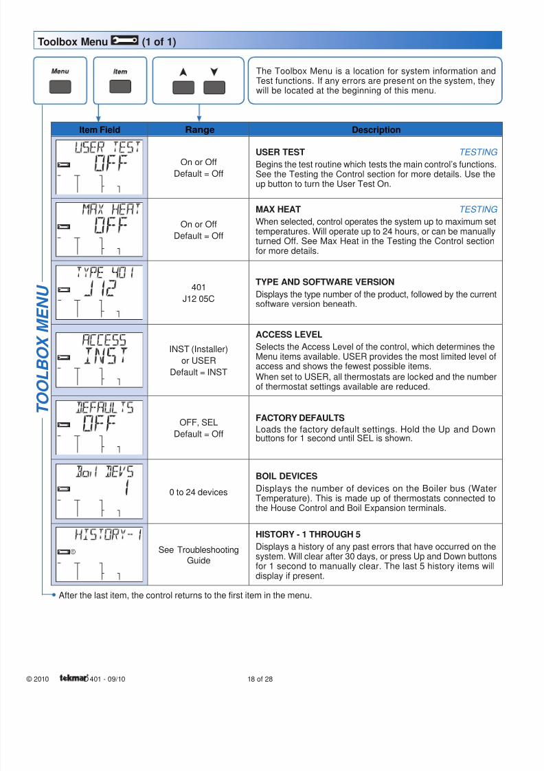
Item Field Range Description
On or Off
Default = Off
USER TEST TESTING
Begins the test routine which tests the main control’s functions.See the Testing the Control section for more details. Use theup button to turn the User Test On.
On or Off
Default = Off
MAX HEAT TESTING
When selected, control operates the system up to maximum settemperatures. Will operate up to 24 hours, or can be manuallyturned Off. See Max Heat in the Testing the Control sectionfor more details.
401
J12 05C
TYPE AND SOFTWARE VERSION
Displays the type number of the product, followed by the currentsoftware version beneath.
INST (Installer)
or USER
Default = INST
ACCESS LEVEL
Selects the Access Level of the control, which determines theMenu items available. USER provides the most limited level ofaccess and shows the fewest possible items.
When set to USER, all thermostats are locked and the numberof thermostat settings available are reduced.
OFF, SEL
Default = Off
FACTORY DEFAULTS
Loads the factory default settings. Hold the Up and Downbuttons for 1 second until SEL is shown.
0 to 24 devices
BOIL DEVICES
Displays the number of devices on the Boiler bus (WaterTemperature). This is made up of thermostats connected tothe House Control and Boil Expansion terminals.
See Troubleshooting
Guide
HISTORY - 1 THROUGH 5
Displays a history of any past errors that have occurred on thesystem. Will clear after 30 days, or press Up and Down buttonsfor 1 second to manually clear. The last 5 history items willdisplay if present.
T O O L B O X M E N U
After the last item, the control returns to the first item in the menu.
The Toolbox Menu is a location for system information andTest functions. If any errors are present on the system, theywill be located at the beginning of this menu.
Toolbox Menu (1 of 1)
8/8/2019 Tekmar 401 tN2 House Control - Boiler, DHW and Setpoint, Four Zone Pumps
http://slidepdf.com/reader/full/tekmar-401-tn2-house-control-boiler-dhw-and-setpoint-four-zone-pumps 19/2819 of 28 © 2010 D 401 - 09/10
Sequence of Operation
tekmarNet ® System Section A
tekmarNet ® is a family of products that use communicationto operate the HVAC system in a comfortable and efficientmanner. The House Control is the central component ina tekmarNet ® system and requires tekmarNet ® 2 (tN2)Thermostats to be directly connected to the control.
The tekmarNet ® 4 (tN4) Expansion terminals can link theHouse Control with other tekmarNet ® components:
Wiring Centers 313, 314, 315, 316 - Add additional zones
tN2 and tN4 Thermostats - Add thermostats
tN4 Timer 033 - Adds 4 programmable schedules
tN4 User Switch 479 - Provides a system override forvacations and holidays
tN4 Setpoint Control 161 - Control hot tubs, pools andmore
•
•
•
•
•
Boiler Temperature Reset Operation Section B
Boiler Call----------------------------------------------------------------------------------------------------------------------------------------------------------------------------------------
Boil Exp Calls
When a device connected to the House Control calls for
heat, the House Control registers a Boil call for hydronicheating on the boiler loop.
When a device connected to the tN4 Boil Expansionterminals calls for heat, the House Control registers a Boil
Expansion call for hydronic heating on the boiler loop.
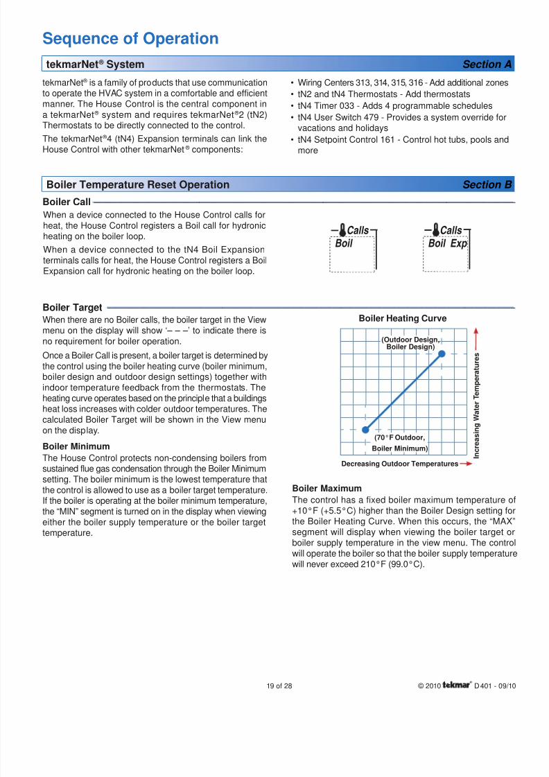
Boiler Target ----------------------------------------------------------------------------------------------------------------------------------------------------------------------------------
When there are no Boiler calls, the boiler target in the Viewmenu on the display will show ‘– – –’ to indicate there isno requirement for boiler operation.
Once a Boiler Call is present, a boiler target is determined bythe control using the boiler heating curve (boiler minimum,boiler design and outdoor design settings) together withindoor temperature feedback from the thermostats. Theheating curve operates based on the principle that a buildings
heat loss increases with colder outdoor temperatures. Thecalculated Boiler Target will be shown in the View menuon the display.
Boiler Minimum
The House Control protects non-condensing boilers fromsustained flue gas condensation through the Boiler Minimumsetting. The boiler minimum is the lowest temperature thatthe control is allowed to use as a boiler target temperature.If the boiler is operating at the boiler minimum temperature,the “MIN” segment is turned on in the display when viewingeither the boiler supply temperature or the boiler targettemperature.
Boiler Heating Curve
(70°F Outdoor,
Boiler Minimum)
Decreasing Outdoor Temperatures I n c r e a s i n g W a t e r T e m p e r a t u r e s
(Outdoor Design,Boiler Design)
Boiler Maximum
The control has a fixed boiler maximum temperature o+10°F (+5.5°C) higher than the Boiler Design setting fothe Boiler Heating Curve. When this occurs, the “MAXsegment will display when viewing the boiler target o
boiler supply temperature in the view menu. The controwill operate the boiler so that the boiler supply temperaturewill never exceed 210°F (99.0°C).
Boil Calls
8/8/2019 Tekmar 401 tN2 House Control - Boiler, DHW and Setpoint, Four Zone Pumps
http://slidepdf.com/reader/full/tekmar-401-tn2-house-control-boiler-dhw-and-setpoint-four-zone-pumps 20/28
© 2010 D 401 - 09/10 20 of 28
Domestic Hot Water Tank Operation Section C
A DHW Call is required in order for the control to provide
heat to a DHW tank. Once the control registers a DHW Call,it will display the “DHW” icon under Calls in the display.This can be done in three ways:
DHW Tank Aquastat
If a DHW aquastat (mechanical switch) is used toapply a DHW Call, the tank is heated to the aqua-stat temperature setting. A dry contact or 24 V (ac)
signal is applied across the DHW Call terminals on theHouse Control.
DHW Tank Sensor
A DHW tank sensor provides superior temperature
control of the tank compared to an aquastat. TheHouse Control automatically detects whether a DHW
sensor is installed. The upper limit of the DHW tem-perature is set by the DHW setting. The DHW tank dif-
ferential is fixed to 6°F (3°C).
•
•
DHW
Calls
DHW Call------------------------------------------------------------------------------------------------------------------------------------------------------------------------------------------
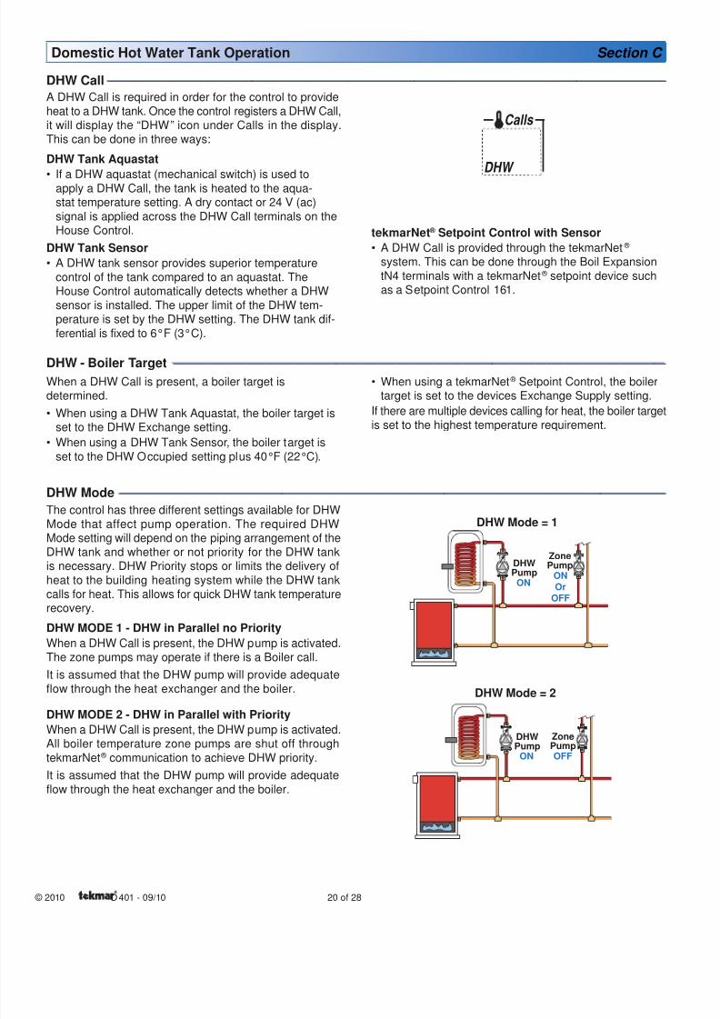
DHW Mode --------------------------------------------------------------------------------------------------------------------------------------------------------------------------------------
The control has three different settings available for DHWMode that affect pump operation. The required DHW
Mode setting will depend on the piping arrangement of theDHW tank and whether or not priority for the DHW tankis necessary. DHW Priority stops or limits the delivery of
heat to the building heating system while the DHW tankcalls for heat. This allows for quick DHW tank temperaturerecovery.
DHW MODE 1 - DHW in Parallel no Priority
When a DHW Call is present, the DHW pump is activated.The zone pumps may operate if there is a Boiler call.
It is assumed that the DHW pump will provide adequate
flow through the heat exchanger and the boiler.
DHW MODE 2 - DHW in Parallel with PriorityWhen a DHW Call is present, the DHW pump is activated.All boiler temperature zone pumps are shut off throughtekmarNet ® communication to achieve DHW priority.
It is assumed that the DHW pump will provide adequateflow through the heat exchanger and the boiler.
DHW - Boiler Target --------------------------------------------------------------------------------------------------------------------------------------------------------------------
When a DHW Call is present, a boiler target isdetermined.
When using a DHW Tank Aquastat, the boiler target isset to the DHW Exchange setting.
When using a DHW Tank Sensor, the boiler target is
set to the DHW Occupied setting plus 40°F (22°C).
•
•
DHWPump
ZonePump
ONOr
OFF
ON
DHW Mode = 1
DHWPump
ZonePumpOFFON
DHW Mode = 2
When using a tekmarNet ® Setpoint Control, the boilertarget is set to the devices Exchange Supply setting.
If there are multiple devices calling for heat, the boiler targetis set to the highest temperature requirement.
•
tekmarNet ® Setpoint Control with Sensor
A DHW Call is provided through the tekmarNet ® system. This can be done through the Boil Expansion
tN4 terminals with a tekmarNet ® setpoint device suchas a Setpoint Control 161.
•
8/8/2019 Tekmar 401 tN2 House Control - Boiler, DHW and Setpoint, Four Zone Pumps
http://slidepdf.com/reader/full/tekmar-401-tn2-house-control-boiler-dhw-and-setpoint-four-zone-pumps 21/2821 of 28 © 2010 D 401 - 09/10
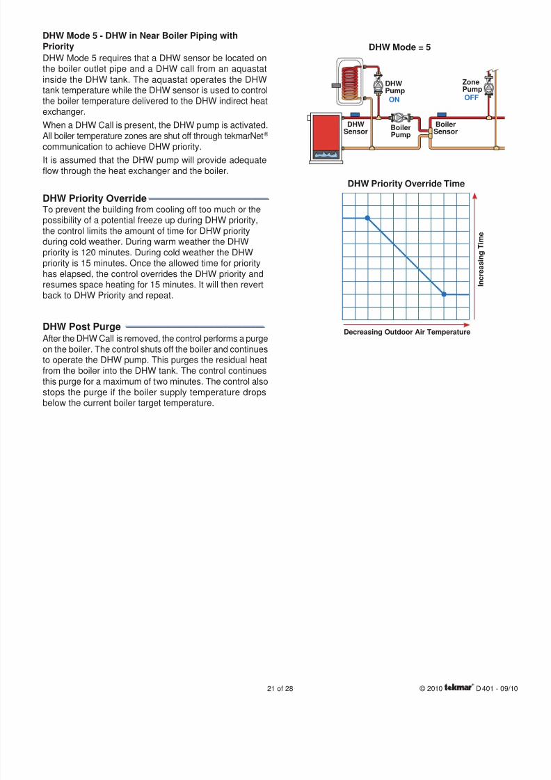
DHW Mode 5 - DHW in Near Boiler Piping withPriority
DHW Mode 5 requires that a DHW sensor be located onthe boiler outlet pipe and a DHW call from an aquastatinside the DHW tank. The aquastat operates the DHWtank temperature while the DHW sensor is used to controlthe boiler temperature delivered to the DHW indirect heatexchanger.
When a DHW Call is present, the DHW pump is activated.
All boiler temperature zones are shut off through tekmarNet ® communication to achieve DHW priority.
It is assumed that the DHW pump will provide adequateflow through the heat exchanger and the boiler.
DHW Priority Override----------------------------------------------------
To prevent the building from cooling off too much or thepossibility of a potential freeze up during DHW priority,
the control limits the amount of time for DHW priorityduring cold weather. During warm weather the DHW
priority is 120 minutes. During cold weather the DHWpriority is 15 minutes. Once the allowed time for priority
has elapsed, the control overrides the DHW priority andresumes space heating for 15 minutes. It will then revertback to DHW Priority and repeat.
DHW Post Purge ------------------------------------------------------------
After the DHW Call is removed, the control performs a purgeon the boiler. The control shuts off the boiler and continuesto operate the DHW pump. This purges the residual heat
from the boiler into the DHW tank. The control continues
this purge for a maximum of two minutes. The control alsostops the purge if the boiler supply temperature dropsbelow the current boiler target temperature.
ON
DHWSensor
OFF
DHWPump
ZonePump
Boiler
Pump
BoilerSensor
DHW Mode = 5
DHW Priority Override Time
I n c r e
a s i n g T i m e
Decreasing Outdoor Air Temperature
8/8/2019 Tekmar 401 tN2 House Control - Boiler, DHW and Setpoint, Four Zone Pumps
http://slidepdf.com/reader/full/tekmar-401-tn2-house-control-boiler-dhw-and-setpoint-four-zone-pumps 22/28
© 2010 D 401 - 09/10 22 of 28
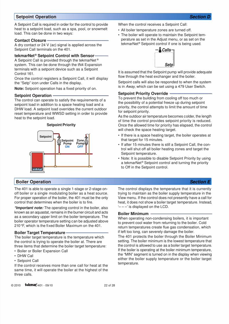
Setpoint Operation Section D
A Setpoint Call is required in order for the control to provideheat to a setpoint load, such as a spa, pool, or snowmeltload. This can be done in two ways:
Contact Closure----------------------------------------------------------------
A dry contact or 24 V (ac) signal is applied across theSetpoint Call terminals on the 401.
tekmarNet ®
Setpoint Control with Sensor--------------A Setpoint Call is provided through the tekmarNet ® system. This can be done through the tN4 Expansion
terminals with a setpoint device such as a SetpointControl 161.
Once the control registers a Setpoint Call, it will displaythe “Setp” icon under Calls in the display.
Note: Setpoint operation has a fixed priority of on.
Setpoint Operation ----------------------------------------------------------
The control can operate to satisfy the requirements of asetpoint load in addition to a space heating load and a
DHW load. A setpoint load overrides the current outdoor
reset temperature and WWSD setting in order to provideheat to the setpoint load.
Setpoint Priority
SetpointPump
ZonePumpOFFON
Setpoint
When the control receives a Setpoint Call:
All boiler temperature zones are turned off.
The boiler will operate to maintain the Setpoint tem-perature as set in the Adjust menu, or as set on thetekmarNet ® Setpoint control if one is being used.
Setp
Calls
It is assumed that the Setpoint pump will provide adequateflow through the heat exchanger and the boiler.
Setpoint calls will also be responded to when the system
is in Away , which can be set using a 479 User Switch.
Setpoint Priority Override --------------------------------------------
To prevent the building from cooling off too much orthe possibility of a potential freeze up during setpoint
priority, the control attempts to limit the amount of timefor setpoint priority.
As the outdoor air temperature becomes colder, the lengthof time the control provides setpoint priority is reduced.Once the allowed time for priority has elapsed, the controlwill check the space heating target.
If there is a space heating target, the boiler operates atthat target for 15 minutes.
If after 15 minutes there is still a Setpoint Call, the con-trol will shut off all boiler heating zones and target the
Setpoint temperature.
Note: It is possible to disable Setpoint Priority by usinga tekmarNet ® Setpoint control and turning the priorityto Off in the Setpoint control.
•
•
•
•
•
Boiler Operation Section E
The 401 is able to operate a single 1-stage or 2-stage on-off boiler or a single modulating boiler as a heat source.For proper operation of the boiler, the 401 must be the onlycontrol that determines when the boiler is to fire.
*Important note: The operating control in the boiler, also
known as an aquastat, remains in the burner circuit and actsas a secondary upper limit on the boiler temperature. Theboiler operator temperature setting can be adjusted above
210°F, which is the fixed Boiler Maximum on the 401.Boiler Target Temperature--------------------------------------------
The boiler target temperature is the temperature which
the control is trying to operate the boiler at. There arethree items that determine the boiler target temperature:
Boiler or Boiler Expansion Call
DHW Call
Setpoint Call
If the control receives more than one call for heat at thesame time, it will operate the boiler at the highest of thethree calls.
•
•
•
The control displays the temperature that it is currentlytrying to maintain as the boiler supply temperature in the
View menu. If the control does not presently have a call forheat, it does not show a boiler target temperature. Instead,‘– – –’ is displayed on the LCD.
Boiler Minimum ----------------------------------------------------------------
When operating non-condensing boilers, it is importantto prevent cool water from returning to the boiler. Cold
return temperatures create flue gas condensation, whichif left too long, can severely damage the boiler.
The 401 protects the boiler through the Boiler Minimumsetting. The boiler minimum is the lowest temperature thatthe control is allowed to use as a boiler target temperature.If the boiler is operating at the boiler minimum temperature,the “MIN” segment is turned on in the display when viewingeither the boiler supply temperature or the boiler targettemperature.
8/8/2019 Tekmar 401 tN2 House Control - Boiler, DHW and Setpoint, Four Zone Pumps
http://slidepdf.com/reader/full/tekmar-401-tn2-house-control-boiler-dhw-and-setpoint-four-zone-pumps 23/2823 of 28 © 2010 D 401 - 09/10
Boiler Maximum----------------------------------------------------------------
The 401 will operate the boiler so that the boiler
supply temperature will never exceed 210°F (99.0°C).The highest allowed boiler target is the boiler designtemperature + 10°F (5.5°C).
Boiler Type--------------------------------------------------------------------------
The 401 can operate either of the following types ofboilers:
One single-stage on-off boiler
One two-stage on-off boiler
Modulating boiler using a 0-10 V (dc) signal
Modulating boiler using a 4-20 mA signal
tekmar EMS signal (for use with multiple boiler
stagers)
EMS signal for Viessmann modulating boilers
On-Off Operation--------------------------------------------------------------
The 401 operates a single hot-water on-off boiler tomaintain the boiler target within a differential. The boilertarget is the average temperature and the boiler supply
temperature can fluctuate by 1/2 of the differential aboveand below of the boiler target.
Modulation Boiler Operation --------------------------------------
The 401 can operate a single hot-water modulating
boiler using the Mod dc/mA output and the Boiler Stagecontact. Not all boilers require the use of the Boiler
Stage contact.
The control operates the boiler by first switching the boilerstage contact to allow the modulating boiler to go throughthe ignition sequence (the boiler stage contact may notbe required on all modulating boilers). A 0-10 V (dc) or 4-20 mA analog signal is then used to modulate the boilerfiring rate star ting from 50% (5 V (dc) or 12 mA signal) for30 seconds.
After the 30 second delay has elapsed, the control willthen allow the boiler to modulate down to the minimummodulation setting and hold it there for the Modulation Delaytime setting. The Modulation Delay setting is determinedby the boiler manufacturer. It is the amount of time thatthe burner must operate before the internal boiler controlallows an external signal to operate the burner.
After the Modulation Delay has elapsed, the control usesPID logic to change the boiler firing rate signal in orderto satisfy the boiler target temperature. When the firingrate signal is reduced down to the Minimum Modulatingsetting and the boiler supply temperature exceeds the
boiler target by 1/2 of the differential, the control will shutoff the burner.
•
•
•
•
•
•
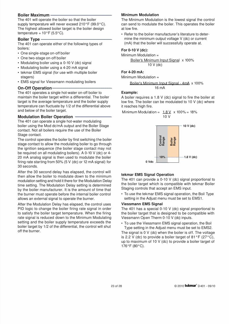
Minimum Modulation
The Minimum Modulation is the lowest signal the controcan send to modulate the boiler. This operates the boiler
at low fire.
Refer to the boiler manufacturer’s literature to deter-mine the minimum output voltage V (dc) or current
(mA) that the boiler will successfully operate at.
For 0-10 V (dc):
Minimum Modulation =Boiler’s Minimum Input Signal x 100%
10 V (dc)
For 4-20 mA:
Minimum Modulation =
Boiler’s Minimum Input Signal - 4mA x 100%
16 mA
Example:
A boiler requires a 1.8 V (dc) signal to fire the boiler alow fire. The boiler can be modulated to 10 V (dc) whereit reaches high fire.
Minimum Modulation = 1.8 V x 100% = 18%10 V
1.8 V (dc)
10 V (dc)
C o n t r o l
R a n g e
B o i l e r
R a n g e
0 Vdc
18%
tekmar EMS Signal Operation
The 401 can provide a 0-10 V (dc) signal proportional tothe boiler target which is compatible with tekmar BoilerStaging controls that accept an EMS input.
To use the tekmar EMS signal operation, the Boil Type
setting in the Adjust menu must be set to EMS1.
Viessmann EMS Signal
The 401 has a special 0-10 V (dc) signal proportional tothe boiler target that is designed to be compatible withViessmann Open Therm 0-10 V (dc) inputs.
To use the Viessmann EMS signal operation, the Boil
Type setting in the Adjust menu must be set to EMS2.The signal is 0 V (dc) when the boiler is of f. The voltage
is 2.2 V (dc) to provide a boiler target of 81°F (27°C)up to maximum of 10 V (dc) to provide a boiler target o176°F (80°C).
•
•
•
8/8/2019 Tekmar 401 tN2 House Control - Boiler, DHW and Setpoint, Four Zone Pumps
http://slidepdf.com/reader/full/tekmar-401-tn2-house-control-boiler-dhw-and-setpoint-four-zone-pumps 24/28
© 2010 D 401 - 09/10 24 of 28
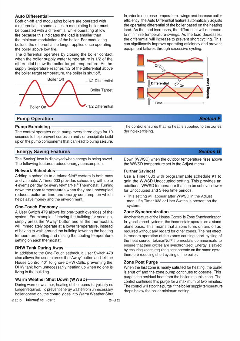
Auto Differential----------------------------------------------------------------
Both on-off and modulating boilers are operated witha differential. In some cases, a modulating boiler mustbe operated with a differential while operating at low
fire because this indicates the load is smaller thanthe minimum modulation of the boiler. For modulating
boilers, the differential no longer applies once operatingthe boiler above low fire.
The differential operates by closing the boiler contact
when the boiler supply water temperature is 1/2 of thedifferential below the boiler target temperature. As thesupply temperature reaches 1/2 of the differential abovethe boiler target temperature, the boiler is shut off.
+1/2 Differential
- 1/2 Differential
Boiler Target
Boiler On
Boiler Off
In order to decrease temperature swings and increase boilerefficiency, the Auto Differential feature automatically adjuststhe operating differential of the boiler based on the heatingload. As the load increases, the differential will decrease
to minimize temperature swings. As the load decreases,the differential will increase to prevent short cycling. This
can significantly improve operating efficiency and preventequipment failures through excessive cycling.
Off
Differential
Time
H e a t i n g
L o a d
On
Pump Operation Section F Pump Exercising ------------------------------------------------------------
The control operates each pump every three days for 10seconds to help prevent corrosion and / or precipitate buildup on the pump components that can lead to pump seizure.
The “$aving” icon is displayed when energy is being saved.The following features reduce energy consumption.
Network Schedules--------------------------------------------------------
Adding a schedule to a tekmarNet ® system is both easy
and valuable. A Timer 033 provides scheduling with up to4 events per day for every tekmarNet ® Thermostat. Turningdown the room temperatures when they are unoccupiedreduces boiler on-time and energy consumption whichhelps save money and the environment.
One-Touch Economy ----------------------------------------------------
A User Switch 479 allows for one-touch overrides of thesystem. For example, if leaving the building for vacation,simply press the “Away” button and all the thermostatswill immediately operate at a lower temperature, insteadof having to walk around the building lowering the heating
temperature setting and raising the cooling temperature
setting on each thermostat.
DHW Tank During Away ----------------------------------------------
In addition to the One-Touch setback, a User Switch 479also allows the user to press the ‘Away’ button and tell the
House Control 401 to ignore DHW Calls, preventing theDHW tank from unnecessarily heating up when no one is
living in the building.
Warm Weather Shut Down (WWSD)------------------------
During warmer weather, heating of the rooms is typically nolonger required. To prevent energy waste from unnecessaryboiler operation, the control goes into Warm Weather Shut
Energy Saving Features Section G
Down (WWSD) when the outdoor temperature rises abovethe WWSD temperature set in the Adjust menu.
Further Savings!
Use a Timer 033 with programmable schedule #1 togain the WWSD Unoccupied setting. This provides anadditional WWSD temperature that can be set even lowerfor Unoccupied and Sleep time periods.
This setting will appear after WWSD in the Adjust
menu if a Timer 033 or User Switch is present on thesystem.
Zone Synchronization --------------------------------------------------
Another feature of the House Control is Zone Synchronization.In typical zoned systems, the thermostats operate on a stand-alone basis. This means that a zone turns on and off asrequired without any regard for other zones. The net effectis random operation of the zones causing short cycling of
the heat source. tekmarNet ® thermostats communicate toensure that their cycles are synchronized. Energy is saved
by ensuring zones requiring heat operate on the same cycle,therefore reducing short cycling of the boiler.
Zone Post Purge ------------------------------------------------------------
When the last zone is nearly satisfied for heating, the boileris shut off and the zone pump continues to operate. Thispurges the residual heat from the boiler into this zone. Thecontrol continues this purge for a maximum of two minutes.The control will stop the purge if the boiler supply temperaturedrops below the boiler minimum setting.
•
The control ensures that no heat is supplied to the zones
during exercising.
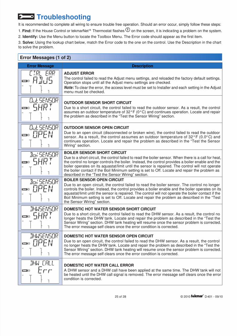
8/8/2019 Tekmar 401 tN2 House Control - Boiler, DHW and Setpoint, Four Zone Pumps
http://slidepdf.com/reader/full/tekmar-401-tn2-house-control-boiler-dhw-and-setpoint-four-zone-pumps 25/2825 of 28 © 2010 D 401 - 09/10
TroubleshootingIt is recommended to complete all wiring to ensure trouble free operation. Should an error occur, simply follow these steps:
1. Find: If the House Control or tekmarNet ® Thermostat flashes on the screen, it is indicating a problem on the system
2. Identify: Use the Menu button to locate the Toolbox Menu. The Error code should appear as the first item.
3. Solve: Using the lookup chart below, match the Error code to the one on the control. Use the Description in the chart
to solve the problem.
Error Messages (1 of 2)Error Message Description
ADJUST ERROR
The control failed to read the Adjust menu settings, and reloaded the factory default settings.Operation stops until all the Adjust menu settings are checked.
Note: To clear the error, the access level must be set to Installer and each setting in the Adjustmenu must be checked.
OUTDOOR SENSOR SHORT CIRCUIT
Due to a short circuit, the control failed to read the outdoor sensor. As a result, the controlassumes an outdoor temperature of 32°F (0°C) and continues operation. Locate and repair
the problem as described in the “Test the Sensor Wiring” section.
OUTDOOR SENSOR OPEN CIRCUIT
Due to an open circuit (disconnected or broken wire), the control failed to read the outdoorsensor. As a result, the control assumes an outdoor temperature of 32°F (0.0°C) andcontinues operation. Locate and repair the problem as described in the “Test the SensorWiring” section.
BOILER SENSOR SHORT CIRCUIT
Due to a short circuit, the control failed to read the boiler sensor. When there is a call for heat,the control no longer controls the boiler. Instead, the control provides a boiler enable and theboiler operates on its aquastat/limit until the sensor is repaired. The control will not operatethe boiler contact if the Boil Minimum setting is set to Off. Locate and repair the problem as
described in the “Test the Sensor Wiring” section.BOILER SENSOR OPEN CIRCUIT
Due to an open circuit, the control failed to read the boiler sensor. The control no longercontrols the boiler. Instead, the control provides a boiler enable and the boiler operates on itsaquastat/limit until the sensor is repaired. The control will not operate the boiler contact if theBoil Minimum setting is set to Off. Locate and repair the problem as described in the “Testthe Sensor Wiring” section.
DOMESTIC HOT WATER SENSOR SHORT CIRCUIT
Due to a short circuit, the control failed to read the DHW sensor. As a result, the control nolonger heats the DHW tank. Locate and repair the problem as described in the “Test theSensor Wiring” section. DHW tank heating will resume once the sensor problem is corrected.The error message self clears once the error condition is corrected.
DOMESTIC HOT WATER SENSOR OPEN CIRCUITDue to an open circuit, the control failed to read the DHW sensor. As a result, the controlno longer heats the DHW tank. Locate and repair the problem as described in the “Test theSensor Wiring” section. DHW tank heating will resume once the sensor problem is corrected.The error message self clears once the error condition is corrected.
DOMESTIC HOT WATER CALL ERROR
A DHW sensor and a DHW call have been applied at the same time. The DHW tank will notbe heated until the DHW call signal is removed. The error message self clears once the errorcondition is corrected.
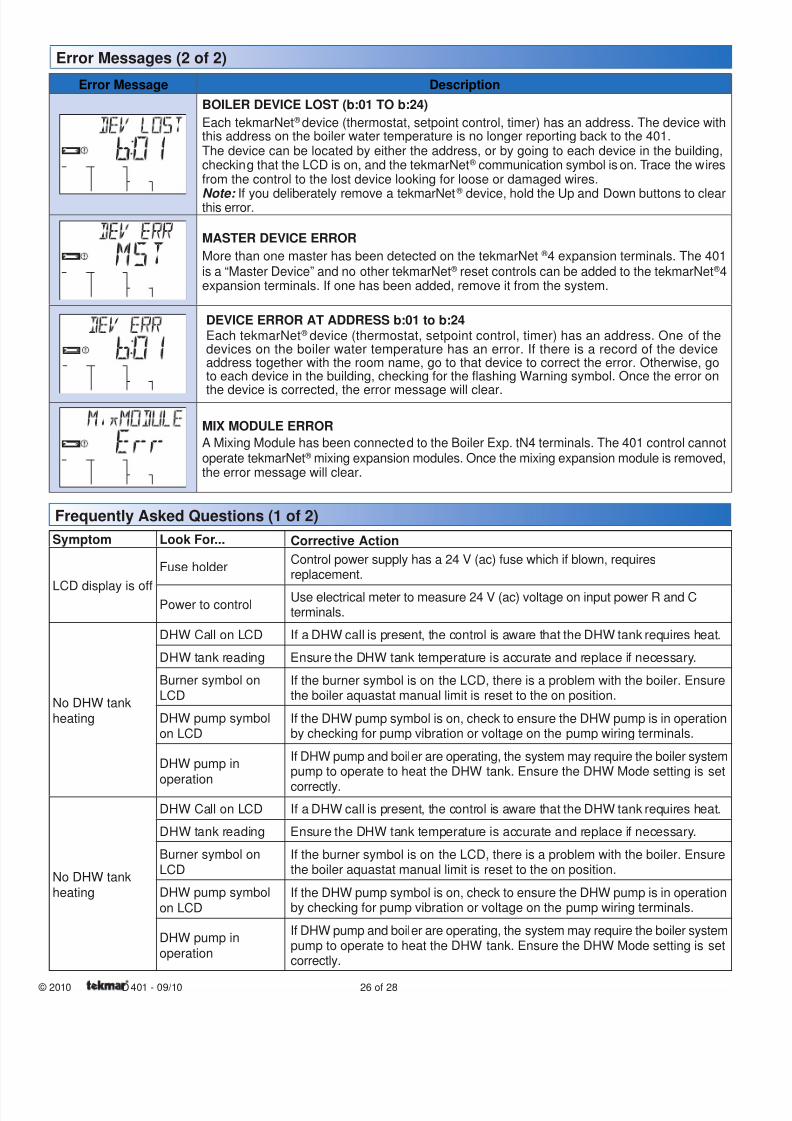
8/8/2019 Tekmar 401 tN2 House Control - Boiler, DHW and Setpoint, Four Zone Pumps
http://slidepdf.com/reader/full/tekmar-401-tn2-house-control-boiler-dhw-and-setpoint-four-zone-pumps 26/28
© 2010 D 401 - 09/10 26 of 28
Error Message Description
BOILER DEVICE LOST (b:01 TO b:24)
Each tekmarNet ® device (thermostat, setpoint control, timer) has an address. The device withthis address on the boiler water temperature is no longer reporting back to the 401.The device can be located by either the address, or by going to each device in the building,checking that the LCD is on, and the tekmarNet ® communication symbol is on. Trace the wiresfrom the control to the lost device looking for loose or damaged wires.
Note: If you deliberately remove a tekmarNet ®
device, hold the Up and Down buttons to clearthis error.
MASTER DEVICE ERROR
More than one master has been detected on the tekmarNet ® 4 expansion terminals. The 401
is a “Master Device” and no other tekmarNet ® reset controls can be added to the tekmarNet ® 4expansion terminals. If one has been added, remove it from the system.
DEVICE ERROR AT ADDRESS b:01 to b:24Each tekmarNet ® device (thermostat, setpoint control, timer) has an address. One of thedevices on the boiler water temperature has an error. If there is a record of the deviceaddress together with the room name, go to that device to correct the error. Otherwise, goto each device in the building, checking for the flashing Warning symbol. Once the error on
the device is corrected, the error message will clear.
MIX MODULE ERROR
A Mixing Module has been connected to the Boiler Exp. tN4 terminals. The 401 control cannotoperate tekmarNet ® mixing expansion modules. Once the mixing expansion module is removed,the error message will clear.
Error Messages (2 of 2)
Symptom Look For... Corrective Action
LCD display is off
Fuse holderControl power supply has a 24 V (ac) fuse which if blown, requiresreplacement.
Power to controlUse electrical meter to measure 24 V (ac) voltage on input power R and Cterminals.
No DHW tank
heating
DHW Call on LCD If a DHW call is present, the control is aware that the DHW tank requires heat.
DHW tank reading Ensure the DHW tank temperature is accurate and replace if necessary.
Burner symbol onLCD
If the burner symbol is on the LCD, there is a problem with the boiler. Ensurethe boiler aquastat manual limit is reset to the on position.
DHW pump symbolon LCD
If the DHW pump symbol is on, check to ensure the DHW pump is in operationby checking for pump vibration or voltage on the pump wiring terminals.
DHW pump in
operation
If DHW pump and boiler are operating, the system may require the boiler systempump to operate to heat the DHW tank. Ensure the DHW Mode setting is set
correctly.
No DHW tank
heating
DHW Call on LCD If a DHW call is present, the control is aware that the DHW tank requires heat.
DHW tank reading Ensure the DHW tank temperature is accurate and replace if necessary.
Burner symbol onLCD
If the burner symbol is on the LCD, there is a problem with the boiler. Ensurethe boiler aquastat manual limit is reset to the on position.
DHW pump symbol
on LCDIf the DHW pump symbol is on, check to ensure the DHW pump is in operationby checking for pump vibration or voltage on the pump wiring terminals.
DHW pump in
operation
If DHW pump and boiler are operating, the system may require the boiler systempump to operate to heat the DHW tank. Ensure the DHW Mode setting is setcorrectly.
Frequently Asked Questions (1 of 2)
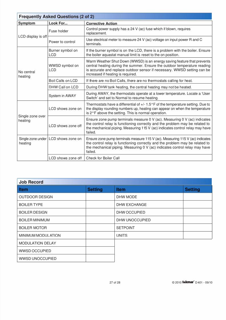
8/8/2019 Tekmar 401 tN2 House Control - Boiler, DHW and Setpoint, Four Zone Pumps
http://slidepdf.com/reader/full/tekmar-401-tn2-house-control-boiler-dhw-and-setpoint-four-zone-pumps 27/2827 of 28 © 2010 D 401 - 09/10
Symptom Look For... Corrective Action
LCD display is off
Fuse holderControl power supply has a 24 V (ac) fuse which if blown, requiresreplacement.
Power to controlUse electrical meter to measure 24 V (ac) voltage on input power R and Cterminals.
No central
heating
Burner symbol on
LCD
If the burner symbol is on the LCD, there is a problem with the boiler. Ensure
the boiler aquastat manual limit is reset to the on position.
WWSD symbol onLCD
Warm Weather Shut Down (WWSD) is an energy saving feature that preventscentral heating during the summer. Ensure the outdoor temperature readingis accurate and replace outdoor sensor if necessary. WWSD setting can beincreased if heating is required.
Boil Calls on LCD If there are no Boil Calls, there are no thermostats calling for heat.
DHW Call on LCD During DHW tank heating, the central heating may not be heated.
System in AWAYDuring AWAY, the thermostats operate at a lower temperature. Locate a ‘UserSwitch’ and set to Normal to resume heating.
Single zone overheating
LCD shows zone onThermostats have a differential of +/- 1.5°F of the temperature setting. Due tothe display rounding numbers up, heating can appear on when the temperature
is 2°F above the setting. This is normal operation.
LCD shows zone off
Ensure zone pump terminals measure 0 V (ac). Measuring 0 V (ac) indicatesthe control relay is functioning correctly and the problem may be related tothe mechanical piping. Measuring 115 V (ac) indicates control relay may havefailed.
Single zone underheating
LCD shows zone on Ensure zone pump terminals measure 115 V (ac). Measuring 115 V (ac) indicatesthe control relay is functioning correctly and the problem may be related tothe mechanical piping. Measuring 0 V (ac) indicates control relay may havefailed.
LCD shows zone off Check for Boiler Call
Frequently Asked Questions (2 of 2)
Item Setting
OUTDOOR DESIGN
BOILER TYPE
BOILER DESIGN
BOILER MINIMUM
BOILER MOTOR
MINIMUM MODULATION
MODULATION DELAY
WWSD OCCUPIED
WWSD UNOCCUPIED
Item Setting
DHW MODE
DHW EXCHANGE
DHW OCCUPIED
DHW UNOCCUPIED
SETPOINT
UNITS
Job Record
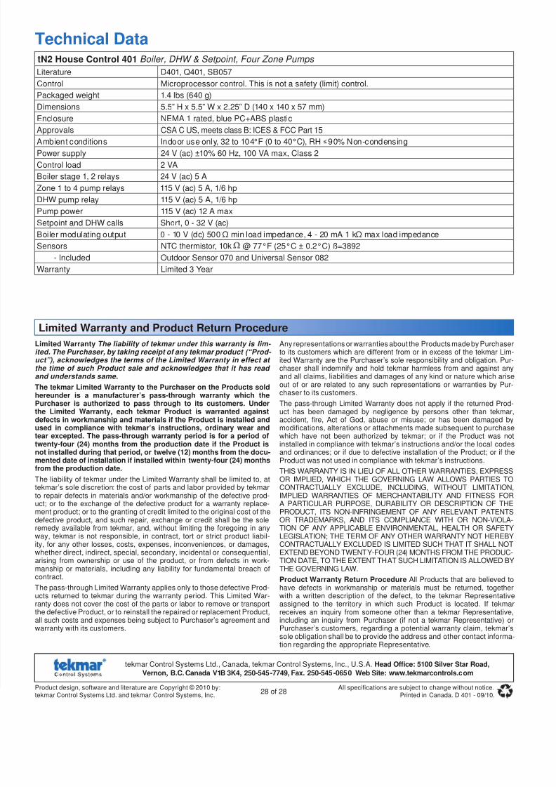
8/8/2019 Tekmar 401 tN2 House Control - Boiler, DHW and Setpoint, Four Zone Pumps
http://slidepdf.com/reader/full/tekmar-401-tn2-house-control-boiler-dhw-and-setpoint-four-zone-pumps 28/28
Limited Warranty The liability of tekmar under this warranty is lim- ited. The Purchaser, by taking receipt of any tekmar product (“Prod- uct”), acknowledges the terms of the Limited Warranty in effect at the time of such Product sale and acknowledges that it has read and understands same.
The tekmar Limited Warranty to the Purchaser on the Products soldhereunder is a manufacturer’s pass-through warranty which thePurchaser is authorized to pass through to its customers. Under
the Limited Warranty, each tekmar Product is warranted againstdefects in workmanship and materials if the Product is installed andused in compliance with tekmar’s instructions, ordinary wear andtear excepted. The pass-through warranty period is for a period oftwenty-four (24) months from the production date if the Product isnot installed during that period, or twelve (12) months from the docu-mented date of installation if installed within twenty-four (24) monthsfrom the production date.
The liability of tekmar under the Limited Warranty shall be limited to, attekmar’s sole discretion: the cost of parts and labor provided by tekmarto repair defects in materials and/or workmanship of the defective prod-uct; or to the exchange of the defective product for a warranty replace-ment product; or to the granting of credit limited to the original cost of thedefective product, and such repair, exchange or credit shall be the soleremedy available from tekmar, and, without limiting the foregoing in anyway, tekmar is not responsible, in contract, tort or strict product liabil-ity, for any other losses, costs, expenses, inconveniences, or damages,
whether direct, indirect, special, secondary, incidental or consequential,arising from ownership or use of the product, or from defects in work-manship or materials, including any liability for fundamental breach ofcontract.
The pass-through Limited Warranty applies only to those defective Prod-ucts returned to tekmar during the warranty period. This Limited War-ranty does not cover the cost of the parts or labor to remove or transportthe defective Product, or to reinstall the repaired or replacement Product,all such costs and expenses being subject to Purchaser’s agreement andwarranty with its customers.
Any representations or warranties about the Products made by Purchaserto its customers which are different from or in excess of the tekmar Lim-ited Warranty are the Purchaser’s sole responsibility and obligation. Pur-chaser shall indemnify and hold tekmar harmless from and against anyand all claims, liabilities and damages of any kind or nature which ariseout of or are related to any such representations or warranties by Pur-chaser to its customers.
The pass-through Limited Warranty does not apply if the returned Prod-
uct has been damaged by negligence by persons other than tekmar,accident, fire, Act of God, abuse or misuse; or has been damaged bymodifications, alterations or attachments made subsequent to purchasewhich have not been authorized by tekmar; or if the Product was notinstalled in compliance with tekmar’s instructions and/or the local codesand ordinances; or if due to defective installation of the Product; or if theProduct was not used in compliance with tekmar’s instructions.
THIS WARRANTY IS IN LIEU OF ALL OTHER WARRANTIES, EXPRESSOR IMPLIED, WHICH THE GOVERNING LAW ALLOWS PARTIES TOCONTRACTUALLY EXCLUDE, INCLUDING, WITHOUT LIMITATION,IMPLIED WARRANTIES OF MERCHANTABILITY AND FITNESS FORA PARTICULAR PURPOSE, DURABILITY OR DESCRIPTION OF THEPRODUCT, ITS NON-INFRINGEMENT OF ANY RELEVANT PATENTSOR TRADEMARKS, AND ITS COMPLIANCE WITH OR NON-VIOLA-TION OF ANY APPLICABLE ENVIRONMENTAL, HEALTH OR SAFETYLEGISLATION; THE TERM OF ANY OTHER WARRANTY NOT HEREBYCONTRACTUALLY EXCLUDED IS LIMITED SUCH THAT IT SHALL NOT
EXTEND BEYOND TWENTY-FOUR (24) MONTHS FROM THE PRODUC-TION DATE, TO THE EXTENT THAT SUCH LIMITATION IS ALLOWED BYTHE GOVERNING LAW.
Product Warranty Return Procedure All Products that are believed tohave defects in workmanship or materials must be returned, togetherwith a written description of the defect, to the tekmar Representativeassigned to the territory in which such Product is located. If tekmarreceives an inquiry from someone other than a tekmar Representative,including an inquiry from Purchaser (if not a tekmar Representative) orPurchaser’s customers, regarding a potential warranty claim, tekmar’ssole obligation shall be to provide the address and other contact informa-tion regarding the appropriate Representative.
Technical DatatN2 House Control 401 Boiler, DHW & Setpoint, Four Zone Pumps
Literature D401, Q401, SB057
Control Microprocessor control. This is not a safety (limit) control.
Packaged weight 1.4 lbs (640 g)
Dimensions 5.5” H x 5.5” W x 2.25” D (140 x 140 x 57 mm)
Enclosure NEMA 1 rated, blue PC+ABS plastic
Approvals CSA C US, meets class B: ICES & FCC Part 15
Ambient conditions Indoor use only, 32 to 104°F (0 to 40°C), RH 90% Non-condensing
Power supply 24 V (ac) ±10% 60 Hz, 100 VA max, Class 2
Control load 2 VA
Boiler stage 1, 2 relays 24 V (ac) 5 A
Zone 1 to 4 pump relays 115 V (ac) 5 A, 1/6 hp
DHW pump relay 115 V (ac) 5 A, 1/6 hp
Pump power 115 V (ac) 12 A max
Setpoint and DHW calls Short, 0 - 32 V (ac)
Boiler modulating output 0 - 10 V (dc) 500 Ω min load impedance, 4 - 20 mA 1 kΩ max load impedance
Sensors NTC thermistor, 10k @ 77°F (25°C ± 0.2°C) ß=3892
- Included Outdoor Sensor 070 and Universal Sensor 082
Warranty Limited 3 Year
Limited Warranty and Product Return Procedure