tekla structures drawings · 2015-08-26 · adding weld marks ... moment connection symbols in...
TRANSCRIPT

Tekla StructuresDrawing Guide
Product version 21.1August 2015
©2015 Tekla Corporation
Contents
1 Tekla Structures drawings.............................................................................. 131.1 Main features in Tekla Structures drawings........................................................................131.2 Drawing mode screen layout................................................................................................. 141.3 Drawing layout and views......................................................................................................161.4 Drawing objects...................................................................................................................... 171.5 Basic principles of drawings.................................................................................................. 18
Drawings integrated with models...............................................................................................................................19How drawings are updated........................................................................................................................................... 19Drawing associativity......................................................................................................................................................20
Associativity symbol.................................................................................................................................................21Different levels of changing drawing properties.................................................................................................... 22
2 Creating drawings........................................................................................... 252.1 Drawing types......................................................................................................................... 26
General arrangement drawings................................................................................................................................... 27Example: Foundation plan......................................................................................................................................28Example: Slab plan................................................................................................................................................... 29Example: Framing plan............................................................................................................................................30Example: Deck plan.................................................................................................................................................. 31Example: Erection elevation drawing..................................................................................................................32Example: 3D isometric drawing............................................................................................................................ 33Example: Anchor bolt plan..................................................................................................................................... 34
Single-part drawings...................................................................................................................................................... 34Example: Anchor bolt...............................................................................................................................................35Example: Embed........................................................................................................................................................ 36Example: Plate........................................................................................................................................................... 37
Assembly drawings.......................................................................................................................................................... 40Example: Beam.......................................................................................................................................................... 40Example: Stairs.......................................................................................................................................................... 41Example: Rail..............................................................................................................................................................42
Cast unit drawings...........................................................................................................................................................42Example: Beam.......................................................................................................................................................... 43Example: Column...................................................................................................................................................... 44Example: Stairs.......................................................................................................................................................... 45
Multidrawings...................................................................................................................................................................45
2.2 Before creating drawings.......................................................................................................462.3 Creating general arrangement drawings..............................................................................472.4 Creating single-part, assembly, or cast unit drawings....................................................... 482.5 Creating multidrawings..........................................................................................................50
Creating empty multidrawings and linking or copying views.............................................................................50Creating multidrawings of the selected drawings..................................................................................................51Creating multidrawings of the selected parts......................................................................................................... 51
2
2.6 Master Drawing Catalog........................................................................................................ 52Master drawing types..................................................................................................................................................... 54
Cloning templates.....................................................................................................................................................55Saved settings............................................................................................................................................................55Rule sets...................................................................................................................................................................... 57Wizards........................................................................................................................................................................ 58
Creating drawings using saved settings in Master Drawing Catalog............................................................... 58Applying detailed object level settings in saved settings.....................................................................................58Creating general arrangement drawings using saved settings in Master Drawing Catalog......................59Creating anchor bolt plans using saved settings....................................................................................................60
Objects included in the anchor bolt plan...........................................................................................................62Defining the anchor bolt plan parts using drawing filters............................................................................62Including assemblies in anchor bolt plans.........................................................................................................63
Creating single-part, assembly and cast unit drawings using saved settings in MasterDrawing Catalog...............................................................................................................................................................64Example: Creating cast unit drawings one by one.................................................................................................65Example: Creating assembly drawings from groups of similar parts................................................................68Creating drawings using rule sets or wizards in Master Drawing Catalog..................................................... 70Example - Creating a new rule set and drawings for all parts........................................................................... 71Creating multiple drawing sheets of the same part.............................................................................................. 76
Creating multiple drawing sheets using wizards .......................................................................................... 77 Creating multiple drawing sheets using drawing properties .....................................................................77
Searching for master drawings in Master Drawing Catalog............................................................................... 78Customizing Master Drawing Catalog.......................................................................................................................79
Adding master drawings in Master Drawing Catalog.................................................................................... 79Adding saved settings..............................................................................................................................................80Adding a rule set....................................................................................................................................................... 80Adding a cloning template.....................................................................................................................................82Removing master drawings from the Master Drawing Catalog.................................................................. 83Modifying master drawing properties.................................................................................................................83Modifying properties of saved settings.............................................................................................................. 84Modifying rule set properties................................................................................................................................ 85Modifying properties and contents of wizard files......................................................................................... 86Wizard file contents.................................................................................................................................................86Modifying cloning template properties.............................................................................................................. 87Managing Master Drawing Catalog folders...................................................................................................... 88Example: Adding, renaming, and moving folders ...........................................................................................90Copying master drawings to another folder..................................................................................................... 90Removing master drawings from a folder..........................................................................................................91Sample images of drawings................................................................................................................................... 91Creating sample images..........................................................................................................................................92Adding sample and thumbnail images to master drawings......................................................................... 92Viewing sample images of drawing templates.................................................................................................93
2.7 Cloning drawings.................................................................................................................... 93Creating drawings using cloning templates in Master Drawing Catalog........................................................94
Cloning by using cloning templates located in other models......................................................................96Cloning from the Drawing List.....................................................................................................................................96
Example: Cloning a general arrangement drawing.........................................................................................98View-specific dimension cloning.................................................................................................................................99Cloned objects................................................................................................................................................................ 100Checking and modifying cloned drawings..............................................................................................................101Refreshing drawing associativity.............................................................................................................................. 102Copying a drawing to a new sheet...........................................................................................................................102Cloning using drawing templates in template library.........................................................................................103
3

3 Finding and opening drawings..................................................................... 1053.1 Opening the Drawing List....................................................................................................1063.2 What is displayed in the Drawing List............................................................................... 1063.3 Drawing status flags.............................................................................................................109
How to read the drawing status information........................................................................................................109
3.4 Modifying Drawing List contents........................................................................................1103.5 Searching drawings and saving the search results............................................................ 1113.6 Selecting drawings in the Drawing List..............................................................................1123.7 Checking whether parts have drawings..............................................................................1123.8 Opening drawings from the model..................................................................................... 1133.9 Opening a new drawing when a drawing is already open................................................ 1133.10 Creating and viewing drawing snapshots...........................................................................1143.11 Taking screenshots in drawings...........................................................................................115
4 Editing drawings............................................................................................ 1174.1 Renaming drawings...............................................................................................................1184.2 Giving titles to drawings......................................................................................................1184.3 Drawing views....................................................................................................................... 119
Adding views in drawings manually........................................................................................................................ 120Creating a section view........................................................................................................................................ 120Creating a curved section view.......................................................................................................................... 123Creating a detail view........................................................................................................................................... 124Defining start number or letter for detail view label and mark................................................................126Creating additional views of parts.................................................................................................................... 126Creating a drawing view of an entire model view........................................................................................127Creating a drawing view of a selected area in a model view....................................................................128Creating a drawing view of a selected area in a drawing view................................................................ 129Creating a drawing view for a reinforcement mesh (RebarMeshViewCreator)....................................129Adding single-part views in assembly drawings........................................................................................... 132
Copying drawing views from another drawing.....................................................................................................133Moving views to another drawing............................................................................................................................134Linking views from another drawing....................................................................................................................... 136Modifying drawing views............................................................................................................................................136
Resizing the drawing view boundary................................................................................................................137Moving drawing views.......................................................................................................................................... 139Aligning drawing views.........................................................................................................................................140Rotating drawing views........................................................................................................................................ 141Arranging drawing views......................................................................................................................................141Modifying drawing view properties.................................................................................................................. 142Modifying section properties.............................................................................................................................. 143Modifying detail properties................................................................................................................................. 144
4.4 Dimensions............................................................................................................................ 145Adding manual dimensions........................................................................................................................................ 146Example: Manual dimensions.................................................................................................................................... 148Adding manual dimensions to general arrangement drawings....................................................................... 152Adding manual dimensions using User Coordinate System..............................................................................152Adding tags to dimensions......................................................................................................................................... 154Example: Filtering out dimension tag content......................................................................................................156
4
Adding dual dimensions manually............................................................................................................................158Recreating dimensions for all parts......................................................................................................................... 159Adding predefined reinforcement dimensions...................................................................................................... 160Adding dimension (distribution) lines to reinforcing bars................................................................................. 161Dimensioning reinforcing bar groups...................................................................................................................... 163Dimensioning center of gravity................................................................................................................................. 167Exaggerating selected dimensions in drawings (ExaggerateSelectedDimensions)..................................... 171Modifying dimension properties............................................................................................................................... 172Adding dimension points in anchor bolt plans..................................................................................................... 173Showing plate side marks........................................................................................................................................... 173Changing the location of short outside dimension texts...................................................................................174Setting new dimension start point...........................................................................................................................175Adding closing dimensions......................................................................................................................................... 176Adding dimension points.............................................................................................................................................177Linking perpendicular dimension lines....................................................................................................................178Combining dimension lines.........................................................................................................................................178Dragging dimension marks......................................................................................................................................... 179Moving the end of the dimension line.................................................................................................................... 180
4.5 Associative annotation objects........................................................................................... 181Adding part marks......................................................................................................................................................... 181Adding level marks........................................................................................................................................................182Adding associative notes.............................................................................................................................................183Modifying associative annotation object properties...........................................................................................184Updating marks..............................................................................................................................................................185Change symbols in drawings......................................................................................................................................186
Removing change symbols...................................................................................................................................187Removing all change symbols from a drawing (RemoveChangeClouds)................................................187
Merging marks............................................................................................................................................................... 189Merging reinforcement marks manually..........................................................................................................190
Dragging the mark and associative note leader line base point......................................................................190Creating and using customized leader line arrows..............................................................................................190
4.6 Independent annotation objects......................................................................................... 192Adding text......................................................................................................................................................................193
Using superscript in text...................................................................................................................................... 194Adding links to text files............................................................................................................................................. 195Adding links to other drawings................................................................................................................................. 197Adding hyperlinks.......................................................................................................................................................... 198Adding links to DWG and DXF files.......................................................................................................................... 199Adding revision marks..................................................................................................................................................200Modifying the properties of independent annotation objects......................................................................... 201
4.7 Drawing shapes.....................................................................................................................201Creating a shape in a drawing...................................................................................................................................202
4.8 Building objects in drawings............................................................................................... 203Modifying building objects.........................................................................................................................................203Shortening parts view by view.................................................................................................................................. 204Hiding building object outlines using cover-up tools.........................................................................................205 Showing a single reinforcing bar in a group .......................................................................................................206
Adjusting the location of a single reinforcing bar........................................................................................ 207Showing layer information on reinforcing bars in drawings (RebarLayeringMarker)................................207
4.9 Custom presentations in drawings..................................................................................... 2094.10 Exploding drawing plug-ins.................................................................................................2104.11 Welds in drawings................................................................................................................ 210
Weld concepts.................................................................................................................................................................211
5
Examples: Model welds in drawings........................................................................................................................ 212Modifying model weld mark visibility and appearance in a drawing.............................................................218Modifying model weld appearance.......................................................................................................................... 220Dragging weld marks....................................................................................................................................................221Adding weld marks........................................................................................................................................................223Example: Weld marks added in drawings...............................................................................................................224Merging weld marks..................................................................................................................................................... 226
4.12 Edge chamfers in drawings................................................................................................. 228Displaying edge chamfers in a drawing..................................................................................................................228Defining default line color and type for edge chamfers.................................................................................... 229Changing edge chamfer line color and type manually.......................................................................................230Creating edge chamfer marks.................................................................................................................................... 231Example: Edge chamfers..............................................................................................................................................231
4.13 Reference models in drawings............................................................................................ 233Setting automatic reference model properties in drawings............................................................................. 234Modifying properties of hidden lines in reference models using advanced options..................................234
4.14 Pours in drawings................................................................................................................. 237Showing pour objects, pour marks and pour breaks in drawings....................................................................238Changing the pour break symbol..............................................................................................................................240 Examples of pour drawings and pour reports .....................................................................................................240
4.15 Grids in drawings..................................................................................................................241Modifying grid and grid line properties.................................................................................................................. 242Dragging grid labels......................................................................................................................................................242Hiding grids or grid lines............................................................................................................................................. 243
4.16 Symbols in drawings.............................................................................................................243Creating and modifying symbol files....................................................................................................................... 244
Viewing and modifying symbol file contents................................................................................................. 244Creating a new symbol file.................................................................................................................................. 245Changing the symbol file in use.........................................................................................................................245
Adding symbols in drawings.......................................................................................................................................246Modifying symbol properties......................................................................................................................................246Moment connection symbols in Tekla Structures drawings (Drawing tools)...............................................247
Creating moment connection symbols (Drawing tools).............................................................................. 247Updating moment connection symbols (Drawing tools).............................................................................250Deleting moment connection symbols (Drawing tools).............................................................................. 250
Adding surface treatment symbols in drawings (AddSurfaceSymbols)..........................................................251
4.17 Changing drawing objects................................................................................................... 252Dragging, reshaping and resizing drawing objects..............................................................................................253Copying with offsets (Drawing tools)......................................................................................................................255Arranging drawing objects..........................................................................................................................................256Hiding and showing objects in drawings and drawing views...........................................................................257
Listing hidden parts in drawings........................................................................................................................260Trimming.......................................................................................................................................................................... 261Splitting............................................................................................................................................................................262Dividing............................................................................................................................................................................ 263Modifying the shape of leader lines.........................................................................................................................263Aligning drawing objects.............................................................................................................................................264Creating fillets in drawings (Drawing tools)..........................................................................................................265Creating chamfers in drawings (Drawing tools)...................................................................................................266Cut lines in Tekla Structures drawings (Drawing tools)..................................................................................... 268
Creating cut lines (Drawing tools).....................................................................................................................269Updating cut lines (Drawing tools)....................................................................................................................270Deleting cut lines (Drawing tools)..................................................................................................................... 270
6
4.18 Colors in drawings................................................................................................................ 271Changing drawing color.............................................................................................................................................. 272Specifying and using special color........................................................................................................................... 274Pen numbers in Color Table........................................................................................................................................ 274
Changing the pen numbers for colors (line weight).....................................................................................275
4.19 User coordinate system (UCS).............................................................................................276Setting a new UCS........................................................................................................................................................ 277Toggling between two user coordinate systems...................................................................................................277Resetting UCS.................................................................................................................................................................277Keyboard shortcuts for UCS........................................................................................................................................278
4.20 Saving drawings....................................................................................................................2784.21 Deleting unnecessary drawing files in single-user mode................................................. 2794.22 Closing drawings...................................................................................................................2804.23 Keyboard shortcuts for drawings........................................................................................280
5 Working with drawings................................................................................ 2825.1 Updating drawings when the model changes....................................................................2825.2 Locking and unlocking drawings........................................................................................ 2835.3 Freezing drawings.................................................................................................................284
Freezing and unfreezing general arrangement drawings.................................................................................. 284Freezing and unfreezing single part, cast unit and assembly drawings........................................................ 285How freezing affects drawings..................................................................................................................................285
5.4 Issuing drawings................................................................................................................... 2865.5 Deleting drawings.................................................................................................................2865.6 Revising drawings.................................................................................................................287
Creating revisions..........................................................................................................................................................287Changing revisions........................................................................................................................................................ 288Deleting revisions.......................................................................................................................................................... 289Revision handling attributes...................................................................................................................................... 289
6 Printing drawings.......................................................................................... 2916.1 Printing to a .pdf file, plot file or printer..........................................................................2926.2 Printing settings and search order .................................................................................... 2966.3 Printing configuration files................................................................................................. 2966.4 Customizing print output file names..................................................................................2976.5 Printing drawings using Tekla Structures printer instances............................................ 300
Printing single drawings..............................................................................................................................................300Example: Printing on A4 in landscape..............................................................................................................301Example: Printing on A3 in portrait.................................................................................................................. 302Example: Printing A3 drawing on A4 paper....................................................................................................302
Printing multiple drawings with different sizes in one go................................................................................ 303Creating PDF files.......................................................................................................................................................... 304Printing to file................................................................................................................................................................ 305
Customizing print file names.............................................................................................................................. 305Switches for customizing print file names......................................................................................................306
Printing to multiple sheets......................................................................................................................................... 308Adding frames and foldmarks in drawings............................................................................................................ 309
Adding frames and foldmarks in printouts......................................................................................................310Adding a DWG/DXF file frame.............................................................................................................................312
7
Setting up printer instances in Printer Catalog.................................................................................................... 312Adding a printer instance.....................................................................................................................................313Adding a print-to-file instance...........................................................................................................................313Adding an Adobe postscript printer instance................................................................................................. 314Defining paper size.................................................................................................................................................315Defining print area h*b..........................................................................................................................................316Colors and line weights in printing................................................................................................................... 316
Printing settings in Print Drawings dialog box..................................................................................................... 317Printing tips.....................................................................................................................................................................318
7 Modifying drawing settings......................................................................... 3207.1 Modifying and saving automatic drawing properties before creating drawings...........3257.2 Modifying drawing properties of an existing drawing.....................................................3267.3 Modifying view-level drawing properties..........................................................................3287.4 Settings affecting the recreation of drawings..................................................................3287.5 Preventing automatic drawing updates and recreation................................................... 3297.6 Modifying and saving drawing object properties..............................................................330
Loading saved drawing object properties in an existing drawing...................................................................330
7.7 Detailed object level settings.............................................................................................. 331Creating detailed object level settings in a general arrangement drawing..................................................331Example: Applying detailed object level settings on drawing level................................................................332Creating detailed object level settings in cast unit drawings.......................................................................... 335Example: Applying detailed object level settings on view level in a cast unit drawing........................... 337
7.8 How Tekla Structures applies drawing properties.............................................................3397.9 Drawing layout..................................................................................................................... 340
Table layouts................................................................................................................................................................... 341Tables................................................................................................................................................................................ 343Creating a new layout..................................................................................................................................................343
Defining fixed sizes................................................................................................................................................ 344Defining calculated sizes......................................................................................................................................345
Creating and adding a new table layout................................................................................................................ 345Setting margins and spaces for drawing views.................................................................................................... 346 Adding tables in a table layout ...............................................................................................................................347Replacing a table with another one.........................................................................................................................347Setting the properties of tables in a table layout................................................................................................348Key plans..........................................................................................................................................................................350
Adding a key plan in a table layout.................................................................................................................. 350Setting up a drawing view to be used as a key plan....................................................................................351
Adding a DXG/DXF file in a table layout.................................................................................................................352Selecting a new layout................................................................................................................................................ 352Modifying tables in Template Editor........................................................................................................................353
7.10 Drawing size and drawing view scale................................................................................. 354Using exact drawing view scale and automatic drawing size..........................................................................354Using exact drawing size and automatic drawing view scale..........................................................................355Autoscaling and autosizing drawings......................................................................................................................356
7.11 Object protection and placement settings in drawings................................................... 357Protected areas.............................................................................................................................................................. 358Protecting areas in drawings......................................................................................................................................361Defining placement settings for annotation objects...........................................................................................362Defining placement settings for dimensions......................................................................................................... 363Defining automatic free or fixed placement of drawing views........................................................................364
8
7.12 Automatic drawing views.................................................................................................... 364Defining the views to create in single-part, assembly and cast unit drawings.......................................... 365Defining automatic view settings for general arrangement drawings.......................................................... 366Defining view labels and view label marks............................................................................................................ 367Setting the view projection type...............................................................................................................................369Including single-part drawings in assembly drawings........................................................................................370 Part orientation in drawing views ..........................................................................................................................372
Changing the coordinate system....................................................................................................................... 372Rotating parts in drawing views........................................................................................................................ 374 Defining plate orientation in drawings ..........................................................................................................376Setting viewing direction for columns in assembly drawings...................................................................378Setting viewing direction for beams and bracings in assembly drawings.............................................378
Showing neighbor parts in views..............................................................................................................................379Shortening and lengthening parts............................................................................................................................380
Shortening a part in the model.......................................................................................................................... 381Lengthening a part in the model........................................................................................................................381Shortening parts in drawing views....................................................................................................................382Lengthening shortened parts in drawing views.............................................................................................384
Unfolding polybeams in drawings............................................................................................................................ 385Undeforming deformed parts in drawings............................................................................................................. 386Showing part openings and recesses in drawings............................................................................................... 387
Additional ways for showing symbols in openings and recesses..............................................................388Setting automatic section view properties............................................................................................................ 390
Examples of section view and mark settings..................................................................................................391Showing section and end view direction marks............................................................................................ 392Setting the location of end views and section views.................................................................................. 394
7.13 Automatic dimension settings............................................................................................ 396Automatic view-level dimensions.............................................................................................................................397
Example: Creating automatic overall and hole dimensions on view level.............................................401Dimensioning rule properties.............................................................................................................................. 409Examples: Dimensions created with view-level dimensioning..................................................................416Creating a drawing view filter for view-level dimensioning......................................................................422
Dimensioning using dimensioning type Integrated.............................................................................................427 Grouping identical objects to the same dimension line ........................................................................... 429Adding elevation dimensions.............................................................................................................................. 430Check dimensions...................................................................................................................................................432Example: Part dimensioning................................................................................................................................ 434Example: Bolt dimensioning................................................................................................................................436Example: Position dimensioning.........................................................................................................................437Example: Closing dimension................................................................................................................................442Example: Combining dimensions....................................................................................................................... 443Example: Combining bolt group dimensions.................................................................................................. 446Example: Forward offset.......................................................................................................................................446Example: Recognizable distance .......................................................................................................................447Example: Preferred dimension side .................................................................................................................. 448Example: Reinforcement dimension..................................................................................................................449
Adding automatic dual dimensions..........................................................................................................................449Modifying dimensions for unfolded parts.............................................................................................................. 450 Creating minimum and maximum position dimensions for bolts .................................................................452Creating dimension line extensions......................................................................................................................... 453Setting the dimension extension line length........................................................................................................ 453Changing the appearance of absolute dimensions..............................................................................................455Creating exaggerated dimensions............................................................................................................................ 456Changing the prefix in radial dimensions...............................................................................................................458Dimensioning plates..................................................................................................................................................... 458
9

Dimensioning profiles...................................................................................................................................................460Sloped dimension texts................................................................................................................................................462Automatic dimensioning of general arrangement drawings............................................................................ 463
Object groups in dimensioning...........................................................................................................................463Dimensioning object groups on different dimension lines.........................................................................464Example: Grid and overall dimensions............................................................................................................. 466Example: Using maximum leader line length options................................................................................. 467Example: Dimensioning parts partly outside the view................................................................................ 469Example: Limiting the number of outside dimensions.................................................................................470Example: Part dimension positioning................................................................................................................470Example: Dimensions in anchor bolt plans..................................................................................................... 476
7.14 Automatic mark settings..................................................................................................... 479Adding automatic marks............................................................................................................................................. 480Setting the visibility of marks....................................................................................................................................482Setting the appearance of mark text, frames and leader line .........................................................................483
Additional ways for modifying part mark leader lines.................................................................................484Placing the base point of the reinforcement mark leader line automatically...................................... 485
Mark location................................................................................................................................................................. 486Setting a predefined location for beam, bracing and column marks...................................................... 487Part mark and surface treatment mark leader line types and mark location....................................... 487Leader line types and mark location for reinforcing bar group marks....................................................488Reinforcement leader line types and mark location.....................................................................................489
Merging marks automatically....................................................................................................................................490Merged part marks.................................................................................................................................................490Merging part marks .............................................................................................................................................. 492Merged reinforcement marks..............................................................................................................................493Merging reinforcement marks automatically.................................................................................................493
Showing mark frames and leader lines for hidden parts................................................................................... 494Unit settings for marks................................................................................................................................................ 495Adding level attributes in part marks......................................................................................................................497 Adding user-defined attributes and template attributes in marks ...............................................................499
Example 1: Creating a mark template containing separate value fields and text elements............ 500Example 2: Creating a mark template containing a formula in the value field...................................502
Adding templates in marks.........................................................................................................................................504Adding symbols in marks.............................................................................................................................................505Defining contents of bolt mark Size element using advanced options......................................................... 506Adding pull-out pictures in reinforcement marks................................................................................................509
7.15 Automatic grid settings in drawings...................................................................................511Setting automatic grid properties.............................................................................................................................512
7.16 Automatic part and neighbor part settings in drawings..................................................512Setting automatic drawing part properties........................................................................................................... 513Example: Part representations................................................................................................................................... 514Setting automatic neighbor part properties.......................................................................................................... 515Indicating part orientation......................................................................................................................................... 516
Using part mark as an orientation mark in general arrangement drawings......................................... 516Displaying compass direction in part marks................................................................................................... 518Displaying orientation marks (north marks)................................................................................................... 519Displaying connecting side marks......................................................................................................................520
7.17 Automatic bolt settings in drawings..................................................................................522Setting automatic bolt properties in drawings.....................................................................................................522Creating user-defined bolt symbols......................................................................................................................... 523Example: Bolt representations...................................................................................................................................524
7.18 Automatic hatch patterns in drawings.............................................................................. 525
10
Adding automatic hatch patterns on drawing objects.......................................................................................526Example: Insulation hatch patterns......................................................................................................................... 528
7.19 Automatic surface treatment in drawings........................................................................ 530Adding automatic surface treatment in drawings...............................................................................................530
7.20 Automatic weld settings in drawings.................................................................................531Setting automatic weld properties in drawings................................................................................................... 531
7.21 Automatic reinforcement and mesh settings in drawings............................................... 532Setting automatic reinforcement and reinforcement mesh properties.........................................................532Example: Hiding reinforcing bar lines in drawings..............................................................................................534Example: Reinforcement representations...............................................................................................................535
7.22 Units and decimals in drawings, reports and templates ................................................. 5367.23 User-defined attributes in drawings.................................................................................. 537
Modifying automatic user-defined drawing attributes......................................................................................538Creating new user-defined drawing attributes.................................................................................................... 539
7.24 Defining a firm folder for images and symbols.................................................................5417.25 Defining customized line types........................................................................................... 542
8 Drawing settings........................................................................................... 5448.1 General arrangement drawing properties..........................................................................5458.2 Single-part, assembly and cast unit drawing properties..................................................5488.3 Layout properties................................................................................................................. 5498.4 View properties in drawings ...............................................................................................5518.5 Section view properties....................................................................................................... 5558.6 Dimension and dimensioning properties............................................................................ 556
General dimension properties.................................................................................................................................... 556Dimension format, precision and unit properties.................................................................................................558Dimension appearance properties............................................................................................................................ 560Dimension mark and dimension tag properties.................................................................................................... 561General dimensioning properties.............................................................................................................................. 562Position dimensioning properties..............................................................................................................................565Part dimensioning properties..................................................................................................................................... 566Bolt dimensioning properties.....................................................................................................................................568 Dimension grouping properties ...............................................................................................................................569Sub-assembly dimensioning properties.................................................................................................................. 570Reinforcement dimensioning properties................................................................................................................. 571Grid and overall dimensioning properties (GA drawings)...................................................................................571Part dimensioning properties (GA drawings).........................................................................................................572
8.7 Mark properties.................................................................................................................... 573Mark appearance and merging properties............................................................................................................. 574Leader line types............................................................................................................................................................577Positioning properties of view label, section and detail marks........................................................................578Drawing weld mark properties...................................................................................................................................578Model weld mark visibility and appearance properties in drawings.............................................................. 580Level mark properties................................................................................................................................................... 582
8.8 Mark elements......................................................................................................................583Common elements in marks.......................................................................................................................................584Part mark elements....................................................................................................................................................... 585Bolt mark elements.......................................................................................................................................................586Reinforcement and neighbor reinforcement mark elements............................................................................587Reinforcement and neighbor reinforcement mesh mark elements.................................................................588
11
Elements in merged reinforcement marks............................................................................................................. 589Connection mark elements.........................................................................................................................................590Surface treatment mark elements............................................................................................................................590Section and detail mark elements............................................................................................................................ 591View, section view and detail view label mark elements...................................................................................591
8.9 Part and neighbor part properties in drawings................................................................. 5928.10 Bolt content and appearance properties in drawings.......................................................5958.11 Surface treatment visibility and content properties in drawings................................... 5978.12 Surface treatment hatch pattern properties (surfacing.htc).......................................... 5978.13 Part and shape hatch pattern properties (.htc)................................................................ 5998.14 Reinforcement/Neighbor reinforcement and mesh properties in drawings................... 6018.15 Reinforcement settings for drawings (rebar_config.inp) ................................................6038.16 Pour object and pour break properties in drawings..........................................................6108.17 Placement properties for annotation objects....................................................................6128.18 Welding properties............................................................................................................... 6128.19 Drawing shape properties.................................................................................................... 6148.20 Drawing grid properties....................................................................................................... 6158.21 Orientation settings............................................................................................................. 616
9 Disclaimer.......................................................................................................618
12

1 Tekla Structures drawings
Tekla Structures drawings contain a large variety of features that help you to create andmanage your drawings efficiently. The drawings consist of three main types of elements:drawing layout, drawing views, and drawing objects. You can select what to include in thedrawing before you create it, and also add necessary objects in an existing drawing.
See also
Main features in Tekla Structures drawings on page 13
Drawing layout and views on page 15
Drawing objects on page 17
Drawing mode screen layout on page 14
Basic principles of drawings on page 18
1.1 Main features in Tekla Structures drawingsTekla Structures includes the following features for drawings:
• All information comes directly from the model, which minimizes the work you have to do.In many cases all you need to do is to check the predefined settings or do some minorediting.
• Up-to-date drawings. The drawings are actually a part of the model. If you revise themodel, Tekla Structures also updates the drawings, so they are always up to date.
• Master Drawing Catalog, which is a fast, efficient and controlled way of creatingdrawings in one centralized location using master drawings.
• Automatic workshop single-part and assembly drawings, and cast unit drawings ofselected parts with predefined settings for layout, views, dimensions, marks, and buildingobjects. View properties are defined separately for each view before a drawing is created.
• Automatic general arrangement drawings and anchor bolt plans of selected views.
• Drawing cloning capabilities.
• Drawing management. Revision control, locking freezing, and issuing drawings.
Tekla Structures drawings 13 Main features in Tekla Structures drawings

• Interactive editing tools that you can use for adding dimensions, various drawing shapes,texts, additional annotations, symbols, and links in the drawings.
• Standard and customized drawing layouts. Tekla Structures contains many ready-to-usestandard drawing layouts. You can also create your own.
• Export capabilities.
• Printing to paper, file and PDF.
See also
Basic principles of drawings on page 18
Modifying drawing settings on page 320
Automatic drawing views on page 364
Creating drawings on page 25
Cloning drawings on page 93
Editing drawings on page 117
Working with drawings on page 282
Printing drawings on page 291
Exporting a drawing to a 2D DWG or DXF file...
1.2 Drawing mode screen layoutWhen you open a drawing, Tekla Structures activates the drawing mode. The menus andicons for the modeling mode are replaced by those of the drawing mode. The model views
Tekla Structures drawings 14 Drawing mode screen layout
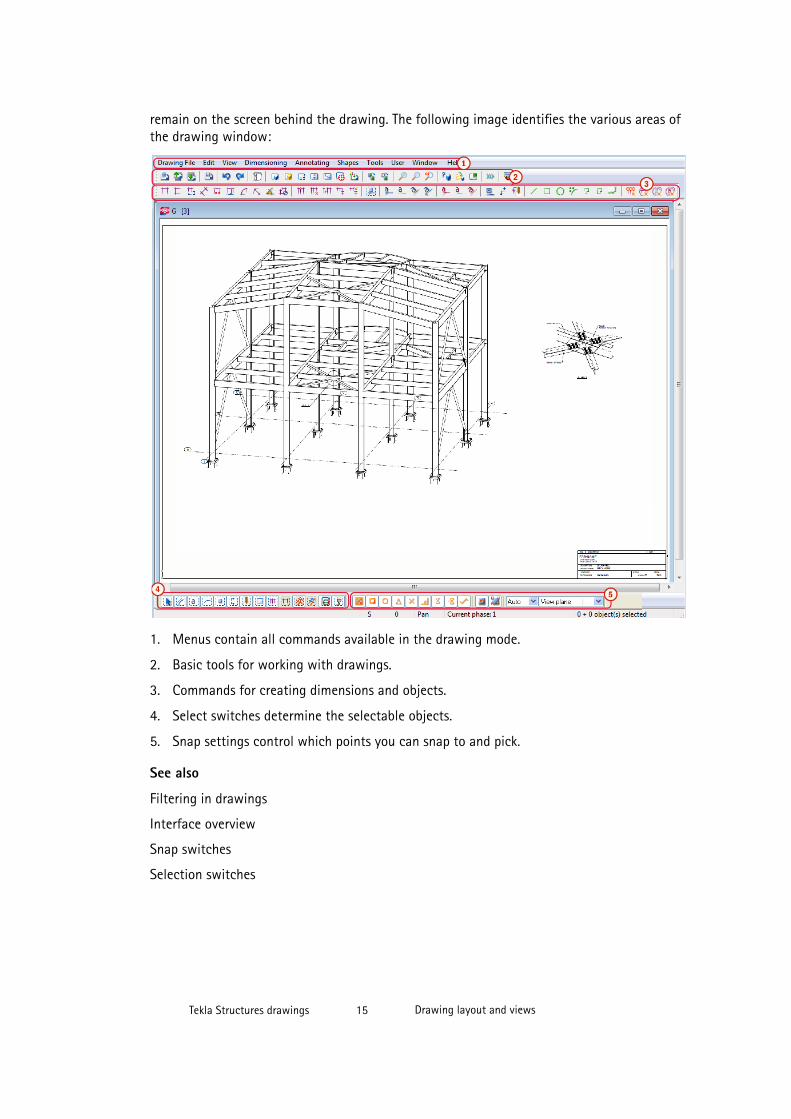
remain on the screen behind the drawing. The following image identifies the various areas ofthe drawing window:
1. Menus contain all commands available in the drawing mode.
2. Basic tools for working with drawings.
3. Commands for creating dimensions and objects.
4. Select switches determine the selectable objects.
5. Snap settings control which points you can snap to and pick.
See also
Filtering in drawings
Interface overview
Snap switches
Selection switches
Tekla Structures drawings 15 Drawing layout and views
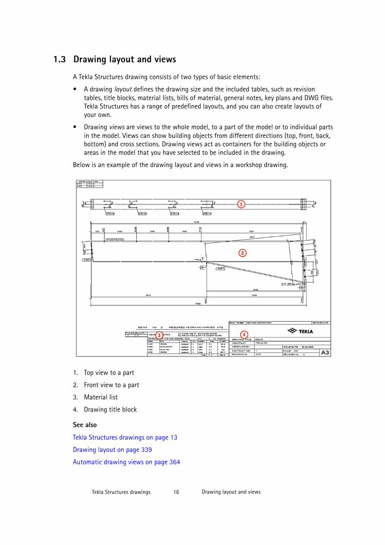
1.3 Drawing layout and views
A Tekla Structures drawing consists of two types of basic elements:
• A drawing layout defines the drawing size and the included tables, such as revisiontables, title blocks, material lists, bills of material, general notes, key plans and DWG files.Tekla Structures has a range of predefined layouts, and you can also create layouts ofyour own.
• Drawing views are views to the whole model, to a part of the model or to individual partsin the model. Views can show building objects from different directions (top, front, back,bottom) and cross sections. Drawing views act as containers for the building objects orareas in the model that you have selected to be included in the drawing.
Below is an example of the drawing layout and views in a workshop drawing.
1. Top view to a part
2. Front view to a part
3. Material list
4. Drawing title block
See also
Tekla Structures drawings on page 13
Drawing layout on page 339
Automatic drawing views on page 364
Tekla Structures drawings 16 Drawing layout and views
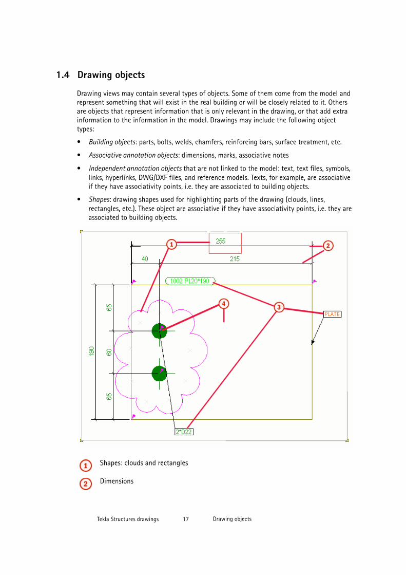
1.4 Drawing objects
Drawing views may contain several types of objects. Some of them come from the model andrepresent something that will exist in the real building or will be closely related to it. Othersare objects that represent information that is only relevant in the drawing, or that add extrainformation to the information in the model. Drawings may include the following objecttypes:
• Building objects: parts, bolts, welds, chamfers, reinforcing bars, surface treatment, etc.
• Associative annotation objects: dimensions, marks, associative notes
• Independent annotation objects that are not linked to the model: text, text files, symbols,links, hyperlinks, DWG/DXF files, and reference models. Texts, for example, are associativeif they have associativity points, i.e. they are associated to building objects.
• Shapes: drawing shapes used for highlighting parts of the drawing (clouds, lines,rectangles, etc.). These object are associative if they have associativity points, i.e. they areassociated to building objects.
Shapes: clouds and rectangles
Dimensions
Tekla Structures drawings 17 Drawing objects

Marks, associative notes
Building objects
See also
Associative annotation objects on page 180
Dimensions on page 145
Independent annotation objects on page 192
Drawing shapes on page 201
Building objects in drawings on page 203
1.5 Basic principles of drawingsThere are a couple of basic principles in Tekla Structures that you need to understand beforeyou start creating or modifying drawings:
• The model is the single source of information for drawings. The drawing is just anotherview to the model, usually a 2D view. This ensures that the information in drawings andreports is always up-to-date.
• Tekla Structures integrates the drawings with the model.
• Drawing objects are associated with model objects, and updated when the modelchanges.
• Changing some of the properties requires the recreation of the drawings.
• If there are several identical parts, cast units or assemblies in the model, Tekla Structurescreates only one drawing.
• You can modify drawing properties on three levels; drawing, view and object level,depending on the drawing type and the desired results.
See also
Drawings integrated with models on page 18
Drawing associativity on page 20
How drawings are updated on page 19
Different levels of changing drawing properties on page 21
Settings affecting the recreation of drawings on page 328
Tekla Structures drawings 18 Basic principles of drawings
Drawings integrated with models
Tekla Structures integrates the drawings with the model. A drawing is a window to the modelpresenting 3D structures in 2D. The building objects shown in the drawing are model objectsyou create in the model. You can change their representation in the drawing but you cannotchange the geometry or the location of the building object, or delete building objects; allchanges to building objects are made in the model. That is why the drawings are always up-to-date. For example, dimensions and marks in drawings are always correct. You can filterout parts and bolts in drawings using the filtering tools, or make them invisible by hidingthem.
You can create drawings at any stage of the project. Creating single-part, assembly and castunit drawings requires that the model is numbered, so you need to plan and perform thenumbering before creating drawings.
If the model changes, Tekla Structures notifies in the Drawing List that you need to updatethe related drawings. You cannot open a drawing that is not up-to-date.
See also
Basic principles of drawings on page 18
Numbering the model
Updating drawings when the model changes on page 282
How drawings are updatedWhen a model changes, the related drawings need to be updated. Tekla Structures takes careof updating and notifies you if updating is needed.
WARNING When you start using a newer version of Tekla Structures, updating drawings createdwith the older version may cause problems. We recommend that you complete anydrawings you have started using the older version, or recreate the drawings using yournew version of Tekla Structures.
Updating is necessary, when:
• The geometry of a model object changes.
• Some other model object properties, for example, material and class change.
• Model objects are added or deleted.
• The number of identical model objects changes.
Tekla Structures automatically updates drawings each time you number the model. If youhave not numbered the model, you are prompted to do so when you create a drawing.Furthermore, if you have changed the model and go to the Drawing List to open drawings,Tekla Structures has marked the outdated drawings, and you need to update them before youcan open them.
General arrangement drawings are always updated when you open them if the model haschanged. You do not need to number the model to update general arrangement drawings.
Tekla Structures drawings 19 Basic principles of drawings
See also
Basic principles of drawings on page 18
Updating drawings when the model changes on page 282
Settings affecting the recreation of drawings on page 328
Numbering the model
Drawing associativity
Tekla Structures drawings are associative. The objects in the drawing are linked to modelobjects, which means that most objects in the drawing are automatically updated when themodel changes. For example, if a model object is resized, dimension points move with thecorresponding object in the drawing, and the dimensions are recalculated. Still you do notlose any manual changes that you have made in the drawing. This applies to all drawingtypes.
Tekla Structures updates the following drawing objects to reflect the changes in the model:
• Parts
• Marks
• Dimensions
• Welds
• Views
• Section marks
• Detail marks
• Associative notes
• Lines and other shapes
• Tables
Tekla Structures retains the following manual changes made to drawings:
• Base points of objects; for example, if you drag an object to a new location
• Object properties; for example, color, font, and line type
See also
Basic principles of drawings on page 18
Associativity symbol on page 20
Tekla Structures drawings 20 Basic principles of drawings
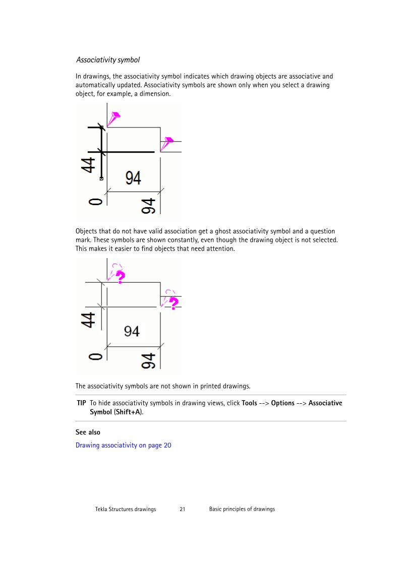
Associativity symbol
In drawings, the associativity symbol indicates which drawing objects are associative andautomatically updated. Associativity symbols are shown only when you select a drawingobject, for example, a dimension.
Objects that do not have valid association get a ghost associativity symbol and a questionmark. These symbols are shown constantly, even though the drawing object is not selected.This makes it easier to find objects that need attention.
The associativity symbols are not shown in printed drawings.
TIP To hide associativity symbols in drawing views, click Tools --> Options --> AssociativeSymbol (Shift+A).
See also
Drawing associativity on page 20
Tekla Structures drawings 21 Basic principles of drawings
Different levels of changing drawing properties
In Tekla Structures, you can change drawings on different levels, depending on howpermanent and extensive changes are needed.
Single-part, assembly and cast unit drawings
• On the highest level, you can define drawing properties on drawing level. Some of thedrawing-specific properties that you define in the Drawing Properties dialog box applyto the whole drawing: protection settings, user-defined attributes for the drawing, detailview start number/letter, drawing-specific section view settings, some drawing-specificview attributes, drawing titles and drawing layout settings. On the drawing level, you canalso select the views that you want to create, and set view, dimensioning, building objectand mark settings separately for each view by going further to the View Propertiesdialog box for the selected view. For example, you can define that all marks have blueframe in one view, or that model weld marks are shown in another view. It is veryimportant to save the view-level properties files in the View Properties dialog box to beable to connect the desired view properties to the views that you select to create. Youcan modify the drawing level properties before you create the drawing and also changethem in the created drawing.
• You can also change drawing properties on view level by double-clicking a view frame inan open drawing, which opens the View Properties dialog box. The changes take placeonly in the views that you have selected in an open drawing. Settings propagate to allobjects in the selected views.
• Finally, you can change drawing properties on object level by double-clicking the objectin an open drawing, which opens an object-specific property dialog box. Propertieschange for the selected object only. The properties changed on the object level are nolonger affected by any property changes on higher levels.
• The recommended way of working is to work from top to bottom, from drawing level toobject level. Set your drawing and automatic drawing view properties as close as possibleto what you want by first attempting this on the drawing level. Then modify anythingelse that needs to be changed on the view level, and finally, if any further cleanup isnecessary, you can make changes on the individual object level. The modifications madeon the drawing level remain when the drawing is recreated due to a model change. Onceyou change properties on the view level you should not go to the drawing level propertiesand modify drawing properties there. Once you have change something at one level,changing something else on the level above may negate the changes you have just made.
General arrangement drawings
• On the highest level, you can change drawing properties on drawing level. This is done inthe Drawing Properties dialog box and its subdialog boxes. This way you can change theproperties of all building objects, marks, dimensions, and views in the drawing at thesame time. For example, you can define that all marks have blue frame. You can modifythe drawing properties before you create the drawing and also change them in thecreated drawing. Property changes propagate to all views and objects in that drawing,except new views that you create after the drawing is created.
Tekla Structures drawings 22 Basic principles of drawings
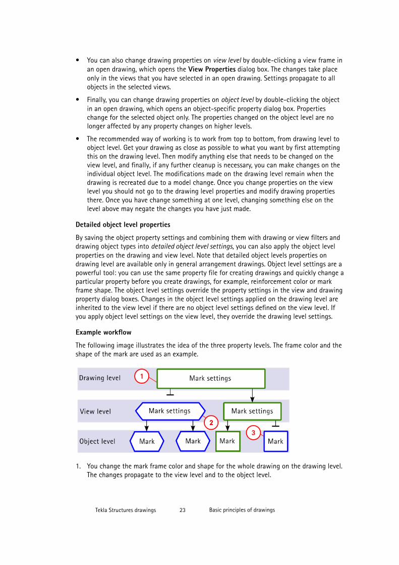
• You can also change drawing properties on view level by double-clicking a view frame inan open drawing, which opens the View Properties dialog box. The changes take placeonly in the views that you have selected in an open drawing. Settings propagate to allobjects in the selected views.
• Finally, you can change drawing properties on object level by double-clicking the objectin an open drawing, which opens an object-specific property dialog box. Propertieschange for the selected object only. The properties changed on the object level are nolonger affected by any property changes on higher levels.
• The recommended way of working is to work from top to bottom, from drawing level toobject level. Get your drawing as close as possible to what you want by first attemptingthis on the drawing level. Then modify anything else that needs to be changed on theview level, and finally, if any further cleanup is necessary, you can make changes on theindividual object level. The modifications made on the drawing level remain when thedrawing is recreated due to a model change. Once you change properties on the viewlevel you should not go to the drawing level properties and modify drawing propertiesthere. Once you have change something at one level, changing something else on thelevel above may negate the changes you have just made.
Detailed object level properties
By saving the object property settings and combining them with drawing or view filters anddrawing object types into detailed object level settings, you can also apply the object levelproperties on the drawing and view level. Note that detailed object levels properties ondrawing level are available only in general arrangement drawings. Object level settings are apowerful tool: you can use the same property file for creating drawings and quickly change aparticular property before you create drawings, for example, reinforcement color or markframe shape. The object level settings override the property settings in the view and drawingproperty dialog boxes. Changes in the object level settings applied on the drawing level areinherited to the view level if there are no object level settings defined on the view level. Ifyou apply object level settings on the view level, they override the drawing level settings.
Example workflow
The following image illustrates the idea of the three property levels. The frame color and theshape of the mark are used as an example.
1. You change the mark frame color and shape for the whole drawing on the drawing level.The changes propagate to the view level and to the object level.
Tekla Structures drawings 23 Basic principles of drawings
2. You change the mark frame color and shape in the selected views. The changes takeplace in the selected views only. The properties do not change in the whole drawing.
Note that if you change the frame color and shape on the drawing level after changingthem on the view level for some of the views, the drawing level changes override theview level changes in all views. In this case, only view settings are not overridden, forexample, the view scale stays as you have set it for individual views.
3. You change the mark frame color and shape in the selected marks. The properties do notchange anywhere else. If you try to change the mark frame color and shape on the viewor drawing level, the properties do not change in the marks that you changed separately.
See also
Modifying and saving automatic drawing properties before creating drawings on page 325
Modifying drawing properties of an existing drawing on page 326
Basic principles of drawings on page 18
Modifying view-level drawing properties on page 327
Modifying and saving drawing object properties on page 330
Creating detailed object level settings in a general arrangement drawing on page 331
Example: Applying detailed object level settings on drawing level on page 332
Creating detailed object level settings in cast unit drawings on page 335
Example: Applying detailed object level settings on view level in a cast unit drawing on page336
Tekla Structures drawings 24 Basic principles of drawings
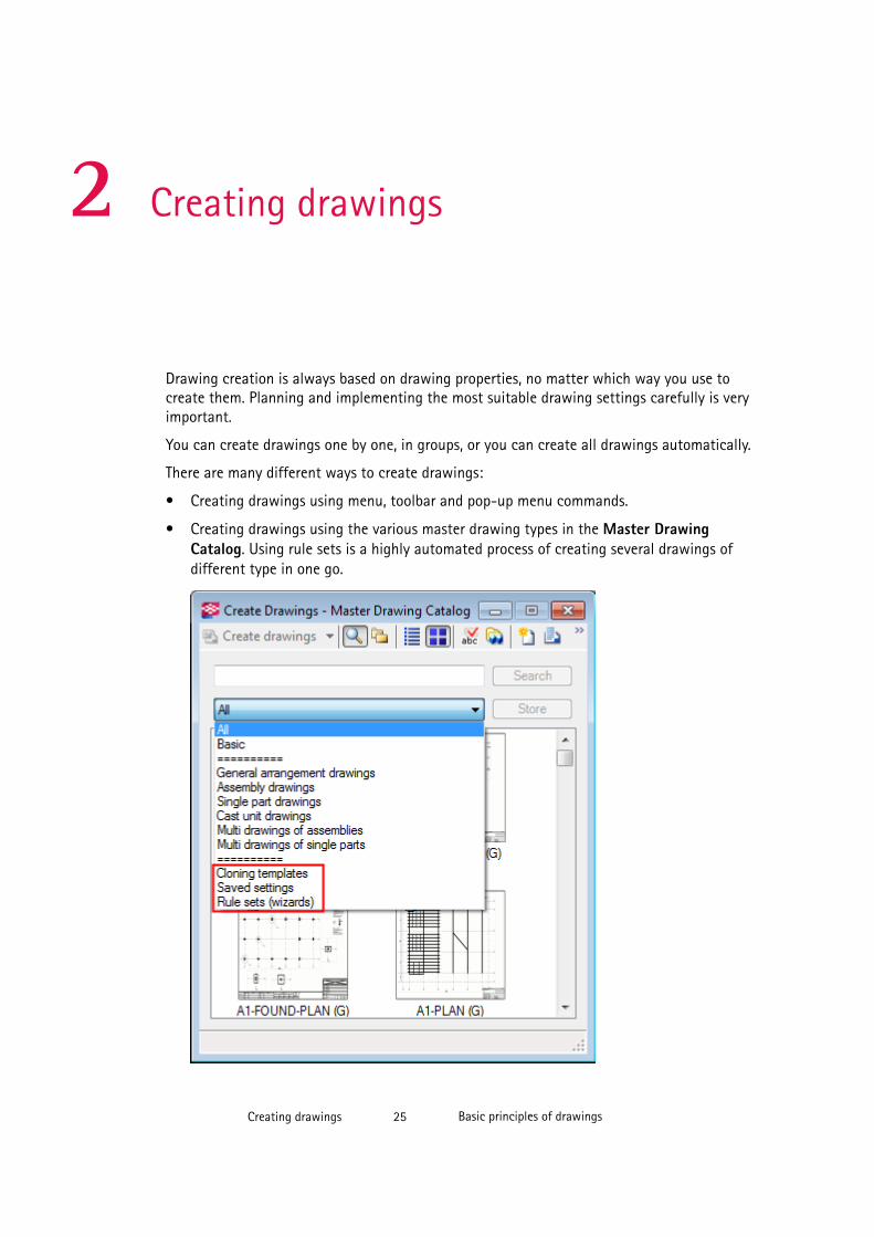
2 Creating drawings
Drawing creation is always based on drawing properties, no matter which way you use tocreate them. Planning and implementing the most suitable drawing settings carefully is veryimportant.
You can create drawings one by one, in groups, or you can create all drawings automatically.
There are many different ways to create drawings:
• Creating drawings using menu, toolbar and pop-up menu commands.
• Creating drawings using the various master drawing types in the Master DrawingCatalog. Using rule sets is a highly automated process of creating several drawings ofdifferent type in one go.
Creating drawings 25 Basic principles of drawings
• Cloning drawings on the basis of cloning templates in the current model or in the cloningtemplate models. You can clone drawings in the Master Drawing Catalog and in theDrawing List.
• You can increase the level of automation even more by applying detailed object levelsettings to all of the above mentioned methods. When the level of automation increases,the need for manual modifications decreases. We recommend that you put extra effort inmaking the automated settings as effective as possible.
Click the links below to find out more:
• Drawing types on page 26
• Before creating drawings on page 46
• Creating general arrangement drawings on page 47
• Creating single-part, assembly, or cast unit drawings on page 48
• Creating multidrawings on page 49
• Master Drawing Catalog on page 52
• Example: Creating cast unit drawings one by one on page 65
• Example: Creating assembly drawings from groups of similar parts on page 68
• Example - Creating a new rule set and drawings for all parts on page 71
• Cloning drawings on page 93
• Creating multiple drawing sheets of the same part on page 76
• Modifying and saving automatic drawing properties before creating drawings on page325
2.1 Drawing typesYou can create many types of drawings in Tekla Structures according to your needs.
Click the links below to find out more:
• General arrangement drawings on page 26
• Single-part drawings on page 34
• Assembly drawings on page 39
• Cast unit drawings on page 42
• Multidrawings on page 45
Creating drawings 26 Drawing types
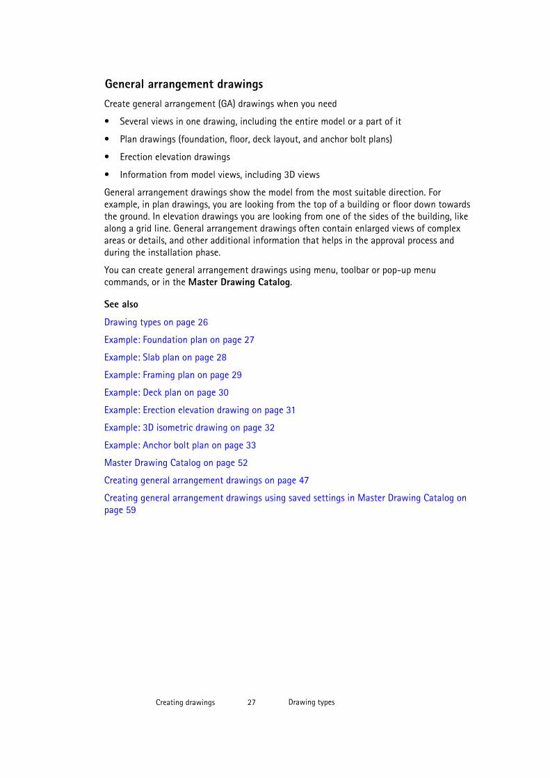
General arrangement drawingsCreate general arrangement (GA) drawings when you need
• Several views in one drawing, including the entire model or a part of it
• Plan drawings (foundation, floor, deck layout, and anchor bolt plans)
• Erection elevation drawings
• Information from model views, including 3D views
General arrangement drawings show the model from the most suitable direction. Forexample, in plan drawings, you are looking from the top of a building or floor down towardsthe ground. In elevation drawings you are looking from one of the sides of the building, likealong a grid line. General arrangement drawings often contain enlarged views of complexareas or details, and other additional information that helps in the approval process andduring the installation phase.
You can create general arrangement drawings using menu, toolbar or pop-up menucommands, or in the Master Drawing Catalog.
See also
Drawing types on page 26
Example: Foundation plan on page 27
Example: Slab plan on page 28
Example: Framing plan on page 29
Example: Deck plan on page 30
Example: Erection elevation drawing on page 31
Example: 3D isometric drawing on page 32
Example: Anchor bolt plan on page 33
Master Drawing Catalog on page 52
Creating general arrangement drawings on page 47
Creating general arrangement drawings using saved settings in Master Drawing Catalog onpage 59
Creating drawings 27 Drawing types
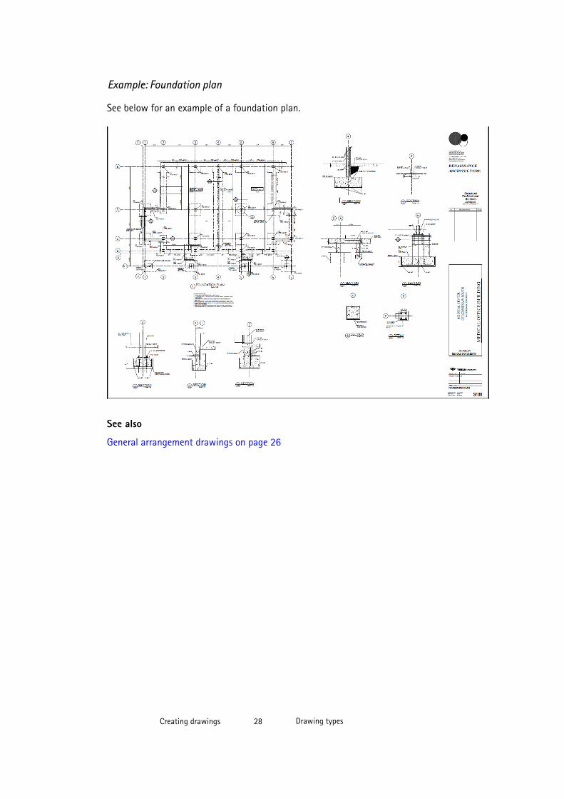
Example: Foundation plan
See below for an example of a foundation plan.
See also
General arrangement drawings on page 26
Creating drawings 28 Drawing types
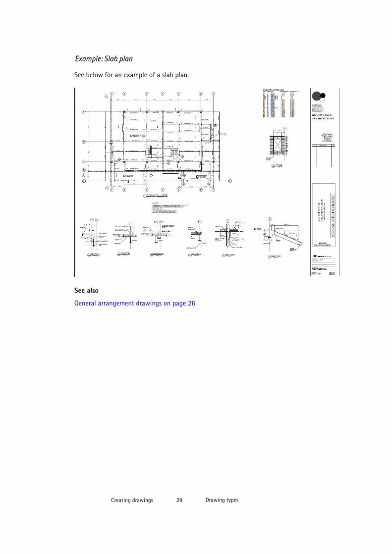
Example: Slab plan
See below for an example of a slab plan.
See also
General arrangement drawings on page 26
Creating drawings 29 Drawing types
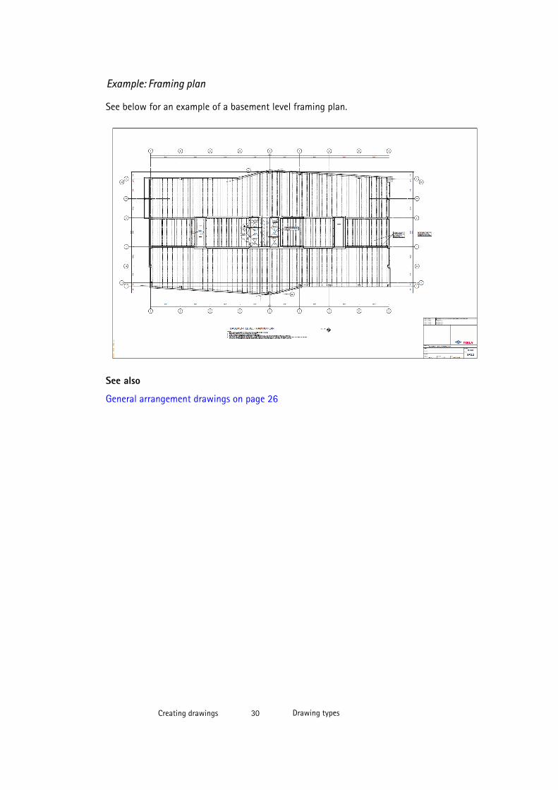
Example: Framing plan
See below for an example of a basement level framing plan.
See also
General arrangement drawings on page 26
Creating drawings 30 Drawing types
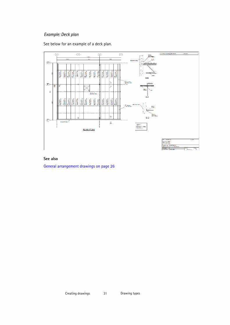
Example: Deck plan
See below for an example of a deck plan.
See also
General arrangement drawings on page 26
Creating drawings 31 Drawing types
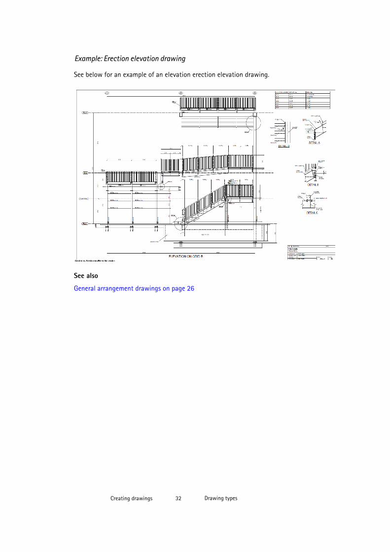
Example: Erection elevation drawing
See below for an example of an elevation erection elevation drawing.
See also
General arrangement drawings on page 26
Creating drawings 32 Drawing types

Example: 3D isometric drawing
See below for an example of an isometric drawing.
See also
General arrangement drawings on page 26
Creating drawings 33 Drawing types
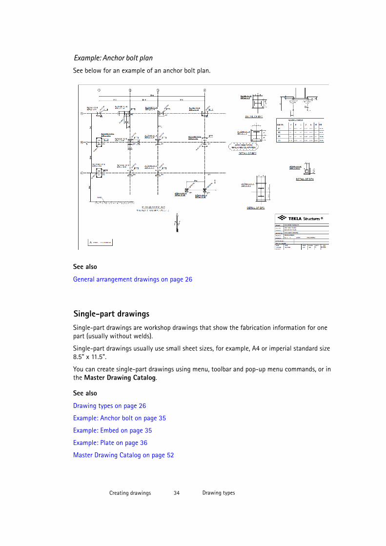
Example: Anchor bolt plan
See below for an example of an anchor bolt plan.
See also
General arrangement drawings on page 26
Single-part drawingsSingle-part drawings are workshop drawings that show the fabrication information for onepart (usually without welds).
Single-part drawings usually use small sheet sizes, for example, A4 or imperial standard size8.5" x 11.5".
You can create single-part drawings using menu, toolbar and pop-up menu commands, or inthe Master Drawing Catalog.
See also
Drawing types on page 26
Example: Anchor bolt on page 35
Example: Embed on page 35
Example: Plate on page 36
Master Drawing Catalog on page 52
Creating drawings 34 Drawing types
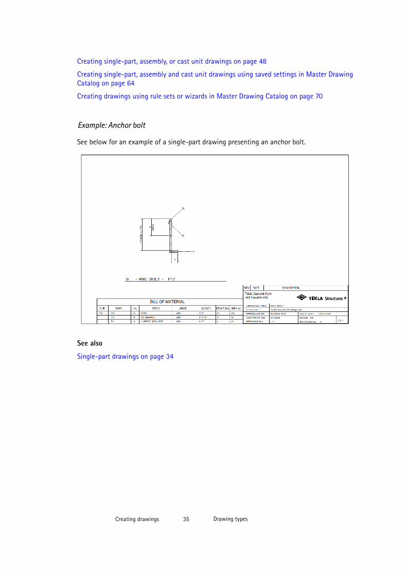
Creating single-part, assembly, or cast unit drawings on page 48
Creating single-part, assembly and cast unit drawings using saved settings in Master DrawingCatalog on page 64
Creating drawings using rule sets or wizards in Master Drawing Catalog on page 70
Example: Anchor bolt
See below for an example of a single-part drawing presenting an anchor bolt.
See also
Single-part drawings on page 34
Creating drawings 35 Drawing types
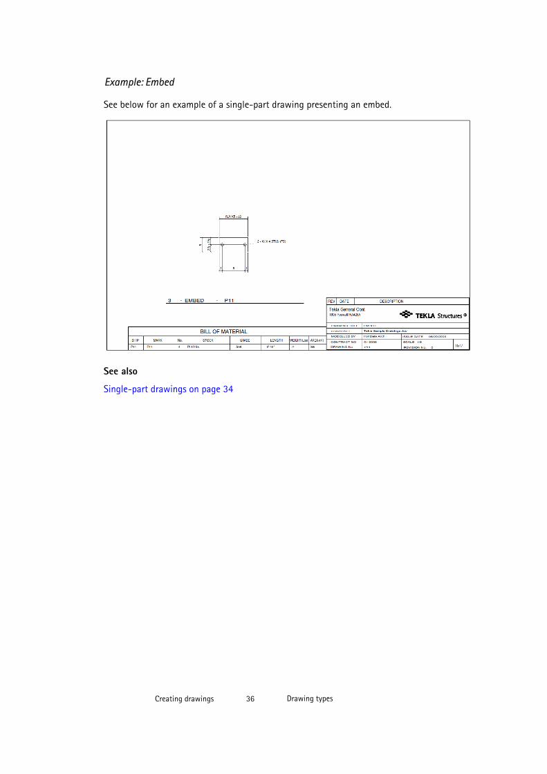
Example: Embed
See below for an example of a single-part drawing presenting an embed.
See also
Single-part drawings on page 34
Creating drawings 36 Drawing types
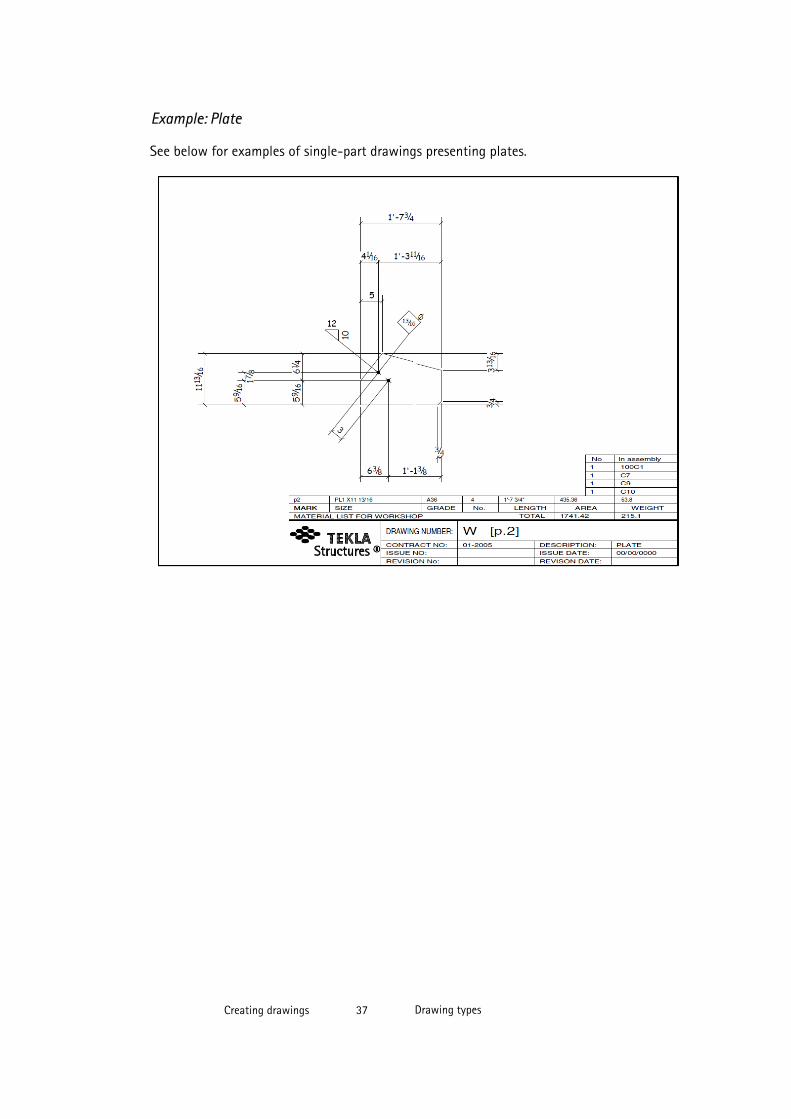
Example: Plate
See below for examples of single-part drawings presenting plates.
Creating drawings 37 Drawing types
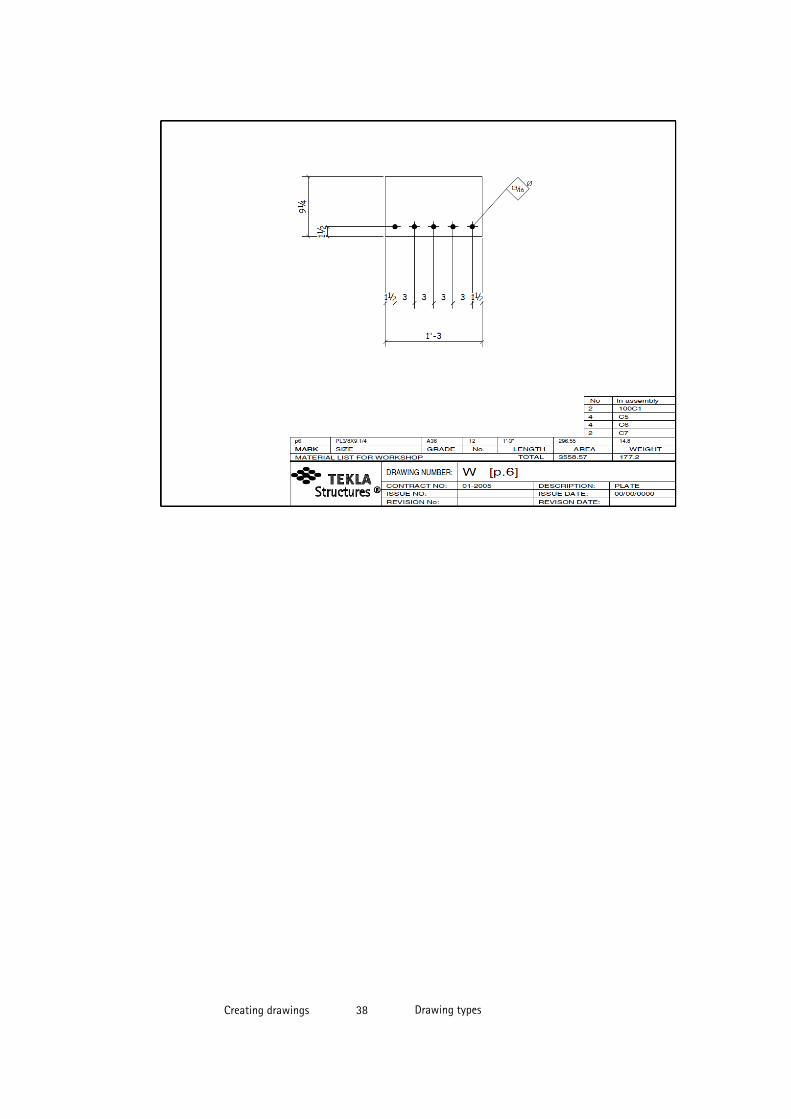
Creating drawings 38 Drawing types
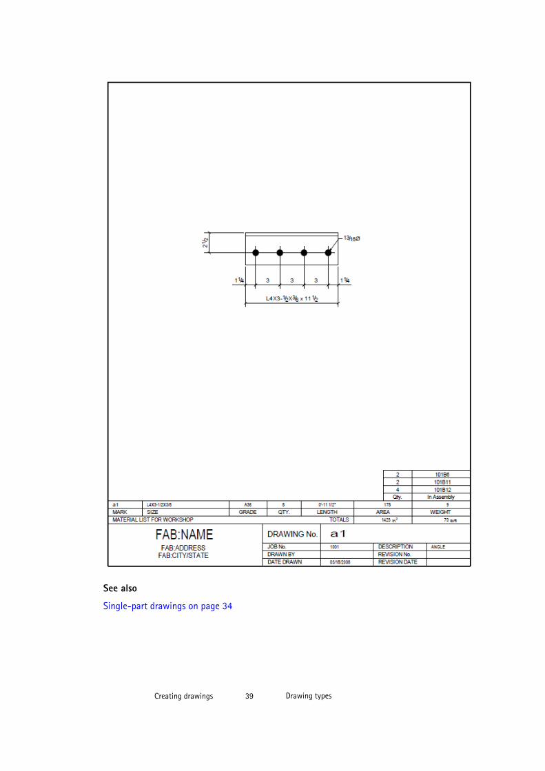
See also
Single-part drawings on page 34
Creating drawings 39 Drawing types
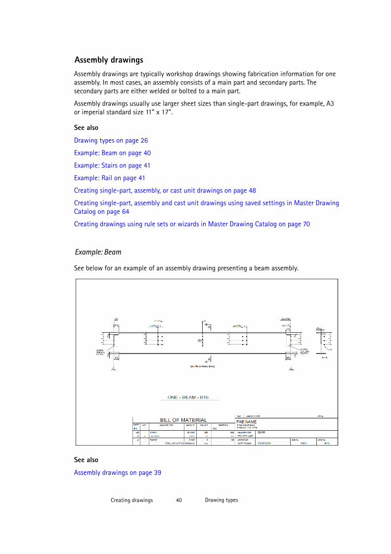
Assembly drawingsAssembly drawings are typically workshop drawings showing fabrication information for oneassembly. In most cases, an assembly consists of a main part and secondary parts. Thesecondary parts are either welded or bolted to a main part.
Assembly drawings usually use larger sheet sizes than single-part drawings, for example, A3or imperial standard size 11" x 17".
See also
Drawing types on page 26
Example: Beam on page 40
Example: Stairs on page 41
Example: Rail on page 41
Creating single-part, assembly, or cast unit drawings on page 48
Creating single-part, assembly and cast unit drawings using saved settings in Master DrawingCatalog on page 64
Creating drawings using rule sets or wizards in Master Drawing Catalog on page 70
Example: Beam
See below for an example of an assembly drawing presenting a beam assembly.
See also
Assembly drawings on page 39
Creating drawings 40 Drawing types
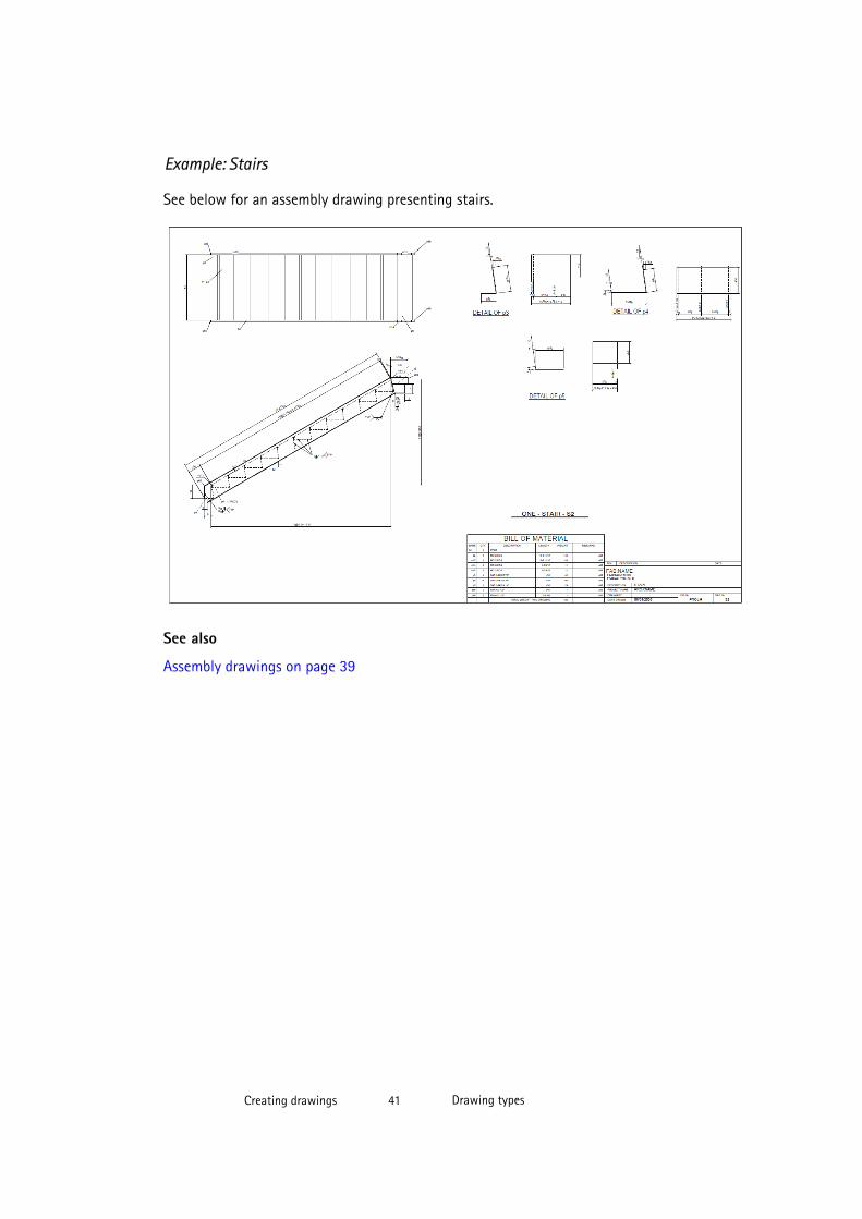
Example: Stairs
See below for an assembly drawing presenting stairs.
See also
Assembly drawings on page 39
Creating drawings 41 Drawing types
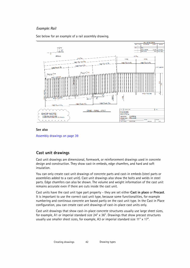
Example: Rail
See below for an example of a rail assembly drawing.
See also
Assembly drawings on page 39
Cast unit drawingsCast unit drawings are dimensional, formwork, or reinforcement drawings used in concretedesign and construction. They show cast-in embeds, edge chamfers, and hard and softinsulation.
You can only create cast unit drawings of concrete parts and cast-in embeds (steel parts orassemblies added to a cast unit). Cast unit drawings also show the bolts and welds in steelparts. Edge chamfers can also be shown. The volume and weight information of the cast unitremains accurate even if there are cuts inside the cast unit.
Cast units have the cast unit type part property - they are set either Cast in place or Precast.It is important to use the correct cast unit type, because some functionalities, for examplenumbering and continous concrete are based partly on the cast unit type. In the Cast in Placeconfiguration, you can create cast unit drawings of cast-in-place cast units only.
Cast unit drawings that show cast-in-place concrete structures usually use large sheet sizes,for example, A1 or imperial standard size 24" x 36". Drawings that show precast structuresusually use smaller sheet sizes, for example, A3 or imperial standard size 11" x 17".
Creating drawings 42 Drawing types

See also
Drawing types on page 26
Example: Beam on page 43
Example: Column on page 43
Example: Stairs on page 44
Creating single-part, assembly, or cast unit drawings on page 48
Creating single-part, assembly and cast unit drawings using saved settings in Master DrawingCatalog on page 64
Creating drawings using rule sets or wizards in Master Drawing Catalog on page 70
Pours in drawings on page 236
Showing pour objects, pour marks and pour breaks in drawings on page 238
Example: Beam
See below for an example of a combined form and reinforcing bar drawing of an inverted teebeam.
See also
Cast unit drawings on page 42
Creating drawings 43 Drawing types
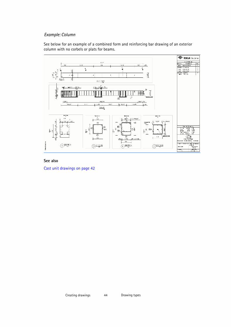
Example: Column
See below for an example of a combined form and reinforcing bar drawing of an exteriorcolumn with no corbels or plats for beams.
See also
Cast unit drawings on page 42
Creating drawings 44 Drawing types
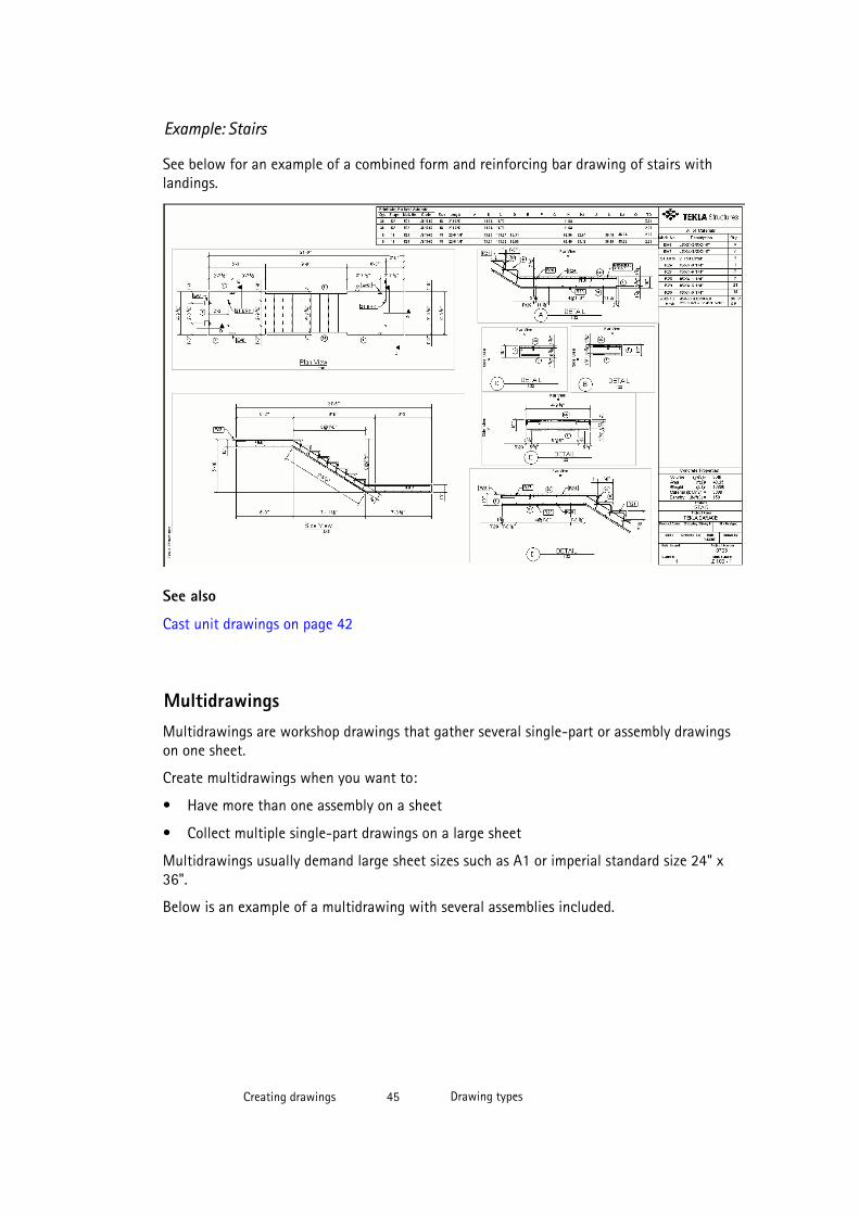
Example: Stairs
See below for an example of a combined form and reinforcing bar drawing of stairs withlandings.
See also
Cast unit drawings on page 42
MultidrawingsMultidrawings are workshop drawings that gather several single-part or assembly drawingson one sheet.
Create multidrawings when you want to:
• Have more than one assembly on a sheet
• Collect multiple single-part drawings on a large sheet
Multidrawings usually demand large sheet sizes such as A1 or imperial standard size 24" x36".
Below is an example of a multidrawing with several assemblies included.
Creating drawings 45 Drawing types

See also
Drawing types on page 26
Creating multidrawings on page 49
2.2 Before creating drawings
The list below contains some things that you may need to do before you create or clonedrawings in Tekla Structures:
• The model needs to be numbered. If the model changes, the numbering needs to beupdated. This applies to assembly, single-part, cast unit and multidrawings only; modeldoes not need to be numbered before creating general arrangement drawings. Numberingensures that Tekla Structures connects the right objects to the right drawings. If you tryto create drawings without numbering the model, Tekla Structures prompts you to do so.You can also number general arrangement drawings, because then parts and marks willhave numbers instead of question marks if you have included part position in part marks.
• Check that the piece is detailed correctly.
• You may want to create test drawings of different types of parts to see how well thepredefined drawing properties, layouts, rule sets (wizards) or cloning templates suit yourneeds.
Creating drawings 46 Before creating drawings
• You may want to modify drawing properties, layouts, or rule sets and save the modifiedsettings for future usage. If you are going to use a drawing as a cloning template, checkthat it contains all the necessary elements for this purpose.
See also
Creating drawings on page 25
Modifying drawing settings on page 320
2.3 Creating general arrangement drawings
Before you create general arrangement drawings, create the model views that you need andensure that the views are as you want them to be in drawings. The drawing views will havethe same orientation and content as the model view you select. Fit work area using twopoints to select the area that you want to show in the general arrangement drawing.
NOTE General arrangement drawings get overwritten if you recreate them. If you want tocreate another general arrangement drawing of the same model view, give anothername to the drawing in drawing properties.
To create general arrangement drawings:
1. Create the model views you need.
If you want to switch between 3D view and plane view in the created view, press Ctrl+P.
2. Click Drawings & Reports --> Drawing Settings --> General Arrangement Drawing...and select the appropriate predefined drawing properties (saved settings) from the list,and then click Load.
Always load predefined properties when you are creating a drawing. When you need tomodify drawing properties, save the new changes to the properties file when necessary.
3. If needed, modify drawing properties and, if necessary, apply object-level settings.
4. Click Apply or OK.
5. Click Drawings & Reports --> Create General Arrangement Drawing , or thecorresponding toolbar command.
Alternatively, you can select the model views from the model (selected views get a redframe), right-click and select Create General Arrangement Drawing from the pop-upmenu.
6. If you have not selected the views yet, select them from the displayed list.
You can use the Shift and Ctrl buttons for selecting several views.
7. In the Options list, select if you want to create one drawing for each selected view oradd all selected views in one drawing.
Creating drawings 47 Creating general arrangement drawings
TIP By selecting Empty, you can create an empty drawing and add drawing views in itafterwards.
8. If you want to open the created drawings, select Open drawing.
9. Click Create.
Tekla Structures creates the drawings and adds them in the Drawing List.
See also
Modifying drawing settings on page 320
General arrangement drawings on page 26
Creating general arrangement drawings using saved settings in Master Drawing Catalog onpage 59
Creating views
General arrangement drawing properties on page 544
Pours in drawings on page 236
2.4 Creating single-part, assembly, or cast unit drawings
Cast units have the cast unit type part property setting in the model - they are set eitherCast in place or Precast. It is important to use the correct cast unit type, because somefunctionalities, for example numbering, are based on the cast unit type. In the Cast in Placeconfiguration, you can create cast unit drawings of cast-in-place cast units only.
To create single-part, assembly, or cast unit drawings:
1. Click Drawings & Reports --> Drawing Settings and select the drawing type.
2. In the drawing properties dialog box, load the appropriate predefined drawing properties(saved settings).
Always load predefined properties when you are creating a drawing. When you need tomodify drawing properties, save the changes to a new properties file when necessary.
Ensure that for cast unit drawings, you use a property file that contains the desired Castunit creation method:
• By cast unit position: A drawing will be created from each cast unit. If there areidentical cast units, one of them will serve as the base cast unit for the drawing. Thisis the most common method for creating cast unit drawings.
• By cast unit ID: Each part in the model includes a unique ID number. You can createdrawings by using cast unit ID numbers. The ID number determines the marking ofthe drawing. You can create several drawings from identical cast units.
Creating drawings 48 Creating single-part, assembly, or cast unit drawings
3. Click View creation, select the view and the properties that you want to change, andclick View properties.
If you do not have any views defined yet, first add the views and then select the viewproperties for the views.
4. If needed, modify the view properties including view, building object, dimensioning andmark settings and apply detailed object-level settings.
5. Click Save to save the view properties.
6. Click OK to return to drawing properties.
7. Click Apply or OK.
8. Select the objects, or use an appropriate selection filter to select the objects you want tocreate drawings from and select the entire model.
Activate only Select parts on the Select switches toolbar when selecting parts.Otherwise selection could take a long time in large models.
9. Do one of the following:
• Click the desired drawing command on the Drawings & Reports menu.
• Click the corresponding toolbar command.
• If you selected individual objects, right-click and select the appropriate drawingcreation command from the pop-up menu.
If you press down Ctrl+Shift while you select the command from the pop-up menu,Tekla Structures opens the created drawing.
10. Number the model if you are prompted to do so.
Tekla Structures creates the drawings. The created drawings are listed in the Drawing List. Ifyou already have a drawing with the same type and mark, Tekla Structures will not create anew one.
TIP To automatically open any drawing after the drawing has been created, hold down Ctrl+Shiftwhile you create the drawing.
See also
Modifying drawing settings on page 320
Pours in drawings on page 236
Showing pour objects, pour marks and pour breaks in drawings on page 238
Single-part, assembly and cast unit drawing properties on page 548
View properties in drawings on page 551
Creating drawings 49 Creating multidrawings

2.5 Creating multidrawings
You can create multidrawings of selected parts and of selected drawings. You can also createempty multidrawings and copy or link views in them from other drawings.
If you create multidrawings from existing drawings, you can choose to include theirindividual drawing layouts. If you want to have separate lists, tables, and call-offs for eachpart or assembly, you should include the individual drawing layouts. You can also include listsand tables for all parts or assemblies in the multidrawing.
Before creating a multidrawing, check the original assembly or single-part drawing, andclean it up, if necessary. Do not do the modifications in the multidrawing that links to theoriginal.
Before you start, you can set XS_MULTIDRAWING_REMOVE_VIEW_LABEL_GAP to TRUE through Tools --> Options --> Advanced Options --> Drawing Properties to removeextra space between drawing view labels and drawing views.
See also
Multidrawings on page 45
XS_MULTIDRAWING_REMOVE_VIEW_LABEL_GAP
Modifying drawing settings on page 320
Creating empty multidrawings and linking or copying views on page 50
Creating multidrawings of the selected drawings on page 51
Creating multidrawings of the selected parts on page 51
Creating empty multidrawings and linking or copying views
You can create empty multidrawings in which you can link or copy views in other drawingswith or without layout.
To create an empty multidrawing and link views:
1. Click Drawings & Reports --> Create Multidrawing --> Empty Drawing .
2. Open the empty multidrawing from the Drawing List.
3. From the Drawing List, select the drawings that you want to link to the multidrawing.
4. Click Views --> Add Views from Other Drawing and select one of the copying or linkingcommands.
The views are placed in the multidrawing.
5. Arrange the views if they are on top of each other.
NOTE When you update multidrawings, also the linked drawings are updated.
Creating drawings 50 Creating multidrawings
What does XS_CREATE_CONNECTION_WHEN_COPYING DRAWING_VIEWS do?
For more information about this advanced option, click What doesXS_CREATE_CONNECTION_WHEN_COPYING DRAWING_VIEWS do?
See also
Creating multidrawings on page 49
Creating multidrawings of the selected drawings
You can create multidrawings of the drawings you select. You can also keep the layout of theselected drawing in the new multidrawing.
To create a multidrawing of selected drawings:
1. Select the drawings from the Drawing List.
2. Click Drawings & Reports --> Create Multidrawing and select one of the followingcommands:
• Selected Drawings: Create multidrawings of the selected drawings without thedrawing layout.
• Selected Drawings with Layout: Create multidrawings of the selected drawings,keeping the layout of each selected drawing.
See also
Creating multidrawings on page 49
Creating multidrawings of the selected parts
Create single-part and assembly drawings of the parts that you select and place the drawingsin a multidrawing. You can also keep the layout of the selected single-part or assemblydrawings.
To create a multidrawing of selected parts:
1. Select the parts using appropriate selection filters.
2. Click Drawings & Reports --> Create Multidrawing and select one of the followingcommands depending on the desired result:
• New Single-Part Drawings of Selected Parts: Create single-part drawings of theselected parts and place the drawings in a multidrawing
• New Single-Part Drawings of Selected Parts with Layout: Create single-partdrawings of the selected part, keeping the layout of each drawing, and place thedrawings in a multidrawing.
Creating drawings 51 Creating multidrawings
• New Assembly Drawings of Selected Parts: Create assembly drawings of theselected parts and place the drawings in a multidrawing.
• New Assembly Drawings of Selected Parts with Layout: Create assembly drawingsof the selected parts, keeping the layout of each drawing, and place the drawings in amultidrawing.
See also
Creating multidrawings on page 49
2.6 Master Drawing CatalogThe Master Drawing Catalog is a fast, efficient and controlled way of creating drawingsusing master drawings. In the Master Drawing Catalog, all drawing creation commands areavailable in one centralized location.
A master drawing is a Tekla Structures drawing or a set of drawing properties that is used forcreating new drawings that look the same as the master drawing. There are several types ofmaster drawings: cloning templates, saved settings and rule sets. You can also use theexisting AutoDrawings wizard files as master drawings.
The example below shows the search view of the Master Drawing Catalog as a thumbnaillist.
Creating drawings 52 Master Drawing Catalog
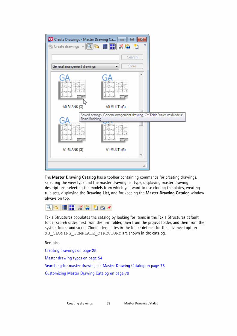
The Master Drawing Catalog has a toolbar containing commands for creating drawings,selecting the view type and the master drawing list type, displaying master drawingdescriptions, selecting the models from which you want to use cloning templates, creatingrule sets, displaying the Drawing List, and for keeping the Master Drawing Catalog windowalways on top.
Tekla Structures populates the catalog by looking for items in the Tekla Structures defaultfolder search order: first from the firm folder, then from the project folder, and then from thesystem folder and so on. Cloning templates in the folder defined for the advanced option XS_CLONING_TEMPLATE_DIRECTORY are shown in the catalog.
See also
Creating drawings on page 25
Master drawing types on page 54
Searching for master drawings in Master Drawing Catalog on page 78
Customizing Master Drawing Catalog on page 79
Creating drawings 53 Master Drawing Catalog
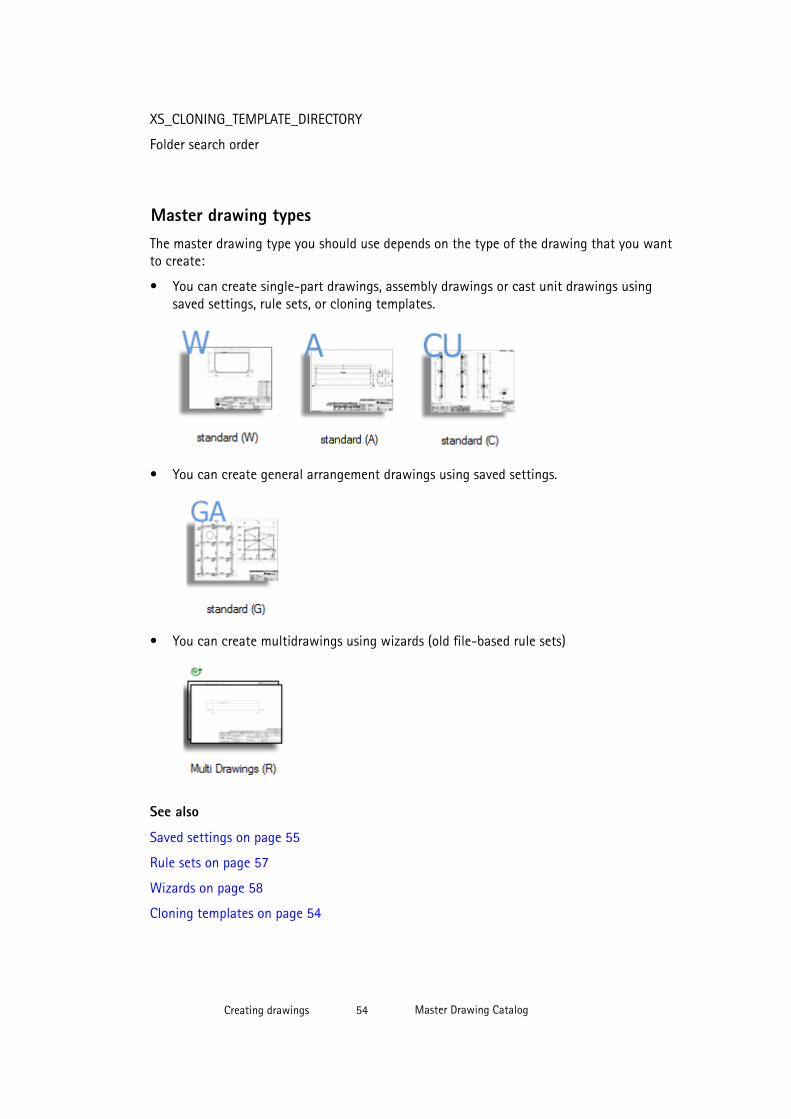
XS_CLONING_TEMPLATE_DIRECTORY
Folder search order
Master drawing typesThe master drawing type you should use depends on the type of the drawing that you wantto create:
• You can create single-part drawings, assembly drawings or cast unit drawings usingsaved settings, rule sets, or cloning templates.
• You can create general arrangement drawings using saved settings.
• You can create multidrawings using wizards (old file-based rule sets)
See also
Saved settings on page 55
Rule sets on page 57
Wizards on page 58
Cloning templates on page 54
Creating drawings 54 Master Drawing Catalog
Cloning templates
Cloning templates are Tekla Structures drawings that are used as templates for creating newdrawings. You can select a drawing from the Drawing List and add it to the Master DrawingCatalog to be used as a template.
You can also use cloning templates that are located in other models. When you have similarparts in several projects, you can maintain a set of cloning template models and then takethe cloning templates in the cloning template models in use when necessary.
See also
Master drawing types on page 54
Cloning drawings on page 93
Creating drawings using cloning templates in Master Drawing Catalog on page 94
Cloning by using cloning templates located in other models on page 95
Adding a cloning template on page 82
Saved settings
The saved settings in Master Drawing Catalog are drawing properties files that have beencreated and saved in the drawing properties dialog boxes for different drawing types. Thereare many predefined drawing property files, and you can also create your own in the drawingproperties dialog boxes.
Each drawing type has its own property files. Default saved settings are located in theenvironment (..\Tekla Structures\<version>\environments\<environment>\system). When you save your own settings, they are saved under thecurrent model directory.
Below some examples how the saved settings are show in the Master Drawing Catalogdialog box.
Creating drawings 55 Master Drawing Catalog
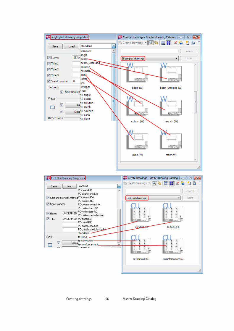
Creating drawings 56 Master Drawing Catalog
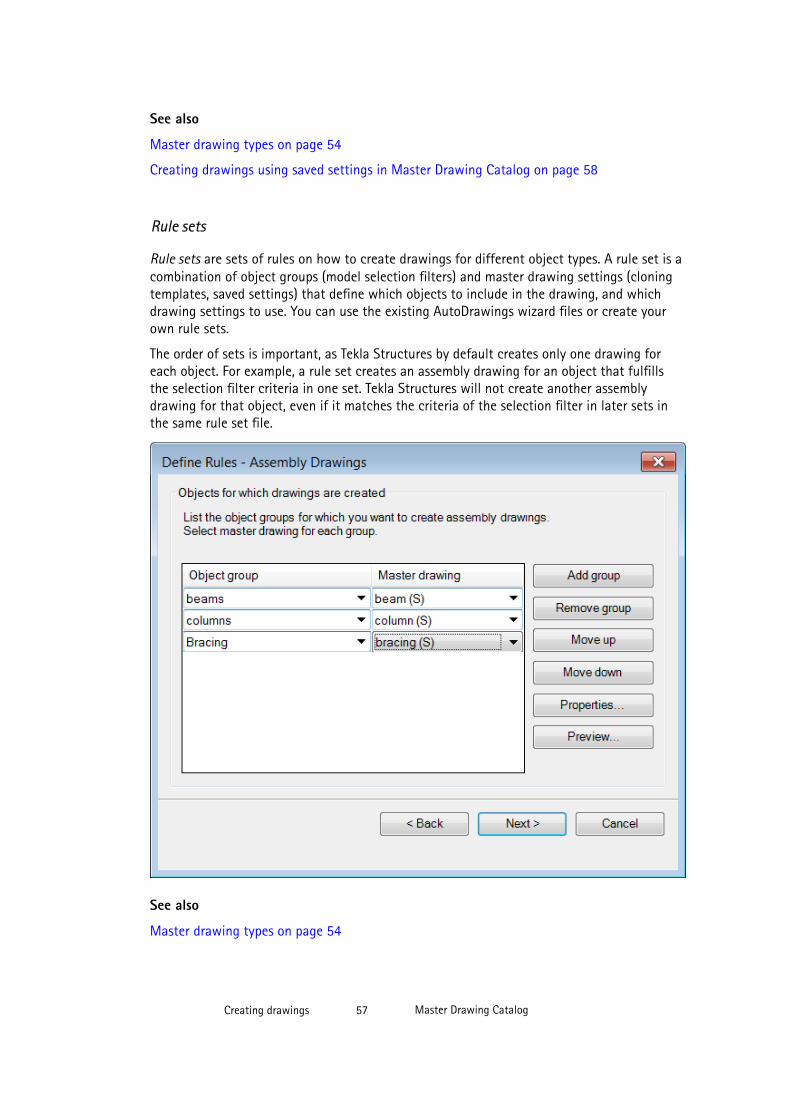
See also
Master drawing types on page 54
Creating drawings using saved settings in Master Drawing Catalog on page 58
Rule sets
Rule sets are sets of rules on how to create drawings for different object types. A rule set is acombination of object groups (model selection filters) and master drawing settings (cloningtemplates, saved settings) that define which objects to include in the drawing, and whichdrawing settings to use. You can use the existing AutoDrawings wizard files or create yourown rule sets.
The order of sets is important, as Tekla Structures by default creates only one drawing foreach object. For example, a rule set creates an assembly drawing for an object that fulfillsthe selection filter criteria in one set. Tekla Structures will not create another assemblydrawing for that object, even if it matches the criteria of the selection filter in later sets inthe same rule set file.
See also
Master drawing types on page 54
Creating drawings 57 Master Drawing Catalog
Creating drawings using rule sets or wizards in Master Drawing Catalog on page 70
Adding a rule set on page 80
Wizards
A wizard file is a file-based wizard consisting of several sets of drawing requests containingdrawing, attribute and part settings to apply to selected objects, as well as a selection filter.The order of sets is important, as Tekla Structures by default creates only one drawing foreach object. You can edit the files in the Master Drawing Catalog. However, creating newwizard files is not possible in the Master Drawing Catalog. Instead, you can create a ruleset, which is basically the same thing as a wizard: It applies drawing properties to objectsselected by filters, but in a dialog box, not in a text file like a wizard.
NOTE In the Master Drawing Catalog, the only way to create multidrawings is to use thewizard files.
See also
Master drawing types on page 54
Creating drawings using rule sets or wizards in Master Drawing Catalog on page 70
Wizard file contents on page 86
Creating drawings using saved settings in Master Drawing Catalog
In Master Drawing Catalog, you can create single-part drawings, assembly drawings, castunit drawings and general arrangement drawings using saved settings (drawing propertyfiles). You can edit the drawing properties of saved settings and apply object level settings.
See also
Applying detailed object level settings in saved settings on page 58
Creating single-part, assembly and cast unit drawings using saved settings in Master DrawingCatalog on page 64
Creating general arrangement drawings using saved settings in Master Drawing Catalog onpage 59
Adding saved settings on page 79
Applying detailed object level settings in saved settings
You can apply drawing object level settings in the drawings that you create in MasterDrawing Catalog for the saved settings type of master drawings. This way you can use thesame saved settings for many drawings and only apply some specific object level settings at
Creating drawings 58 Master Drawing Catalog
the point when you create the drawing, for example, use different kind of marks or changethe reinforcement color.
To apply detailed object level settings in saved settings for a general arrangement drawing:
1. In the Master Drawing Catalog, double-click the saved setting you want to use forcreating drawings.
2. In the Master Drawing Properties dialog box, click Edit drawing properties
3. Click the toggle button at the bottom to empty the check boxes.
4. In the Drawing Properties dialog box, select only the Use detailed object level settingscheck box and ensure that the Yes button next to it is selected.
5. Click Edit settings.
6. Select the filter to be used, the drawing object type and the drawing object property fileto be used.
7. Click OK.
8. Click Save on the top of the dialog box to save the changes in the saved settings file(property file).
9. Click OK in the Master Drawing Properties dialog box.
10. Create the drawings.
NOTE In single-part, assembly and cast unit drawings, you need to go from the Drawing Propertiesdialog box further to the view properties of the view where you want apply detailed objectlevel settings.
See also
Modifying properties of saved settings on page 84
Creating detailed object level settings in a general arrangement drawing on page 331
Example: Applying detailed object level settings on drawing level on page 332
Creating detailed object level settings in cast unit drawings on page 335
Example: Applying detailed object level settings on view level in a cast unit drawing on page336
Creating general arrangement drawings using saved settings in MasterDrawing Catalog
Before you create general arrangement drawings, create the model views that you need andensure that the views are as you want them to be. The drawing views will have the same
Creating drawings 59 Master Drawing Catalog

orientation and content as the model view you select. Fit work area using two points toselect the area that you want to show in the general arrangement drawing.
To create general arrangement drawings using saved settings:
1. In the model, click Drawings & Reports --> Create Drawings .
2. Select the set of saved settings (drawing properties file) from the list.
3. If needed, modify the drawing properties by double-clicking the saved setting andclicking Edit drawing properties.
Remember to save the changes in the properties file.
4. Click Create drawings (Alt+C).
5. In the Create General Arrangement Drawing dialog box, select the views that you wantto create and the desired option from the Options list.
If you select Empty, you can create an empty drawing and add drawing views in itafterwards.
6. Click Create to create the drawings.
Tekla Structures creates the drawings and adds them in the Drawing List. Click in theMaster Drawing Catalog toolbar to open the Drawing List.
NOTE General arrangement drawings get overwritten if you recreate them. If you want to createanother general arrangement drawing of the same model view, give another name to the newdrawing in drawing properties.
For more information about creating cast in place general arrangement drawings, see Poursin drawings on page 236
See also
Saved settings on page 55
Creating drawings using saved settings in Master Drawing Catalog on page 58
Creating general arrangement drawings on page 47
Creating anchor bolt plans using saved settings
Anchor bolt plans are general arrangement drawings showing the anchor bolt layout. You cancreate anchor bolt plans in Master Drawing Catalog or using menu, pop-up menu andtoolbar commands. Here we will create an anchor bolt plan using the Master DrawingCatalog.
WARNING Define the drawing as an anchor bolt plan when you are creating the drawing.You cannot convert a general arrangement drawing to an anchor bolt planafterwards.
Creating drawings 60 Master Drawing Catalog
Before creating the anchor bolt plan, create a model view that is in the xy-plane.
To create an anchor bolt plan:
1. Click Drawings & Reports --> Create Drawings .
2. Double-click a saved setting that has been created for anchor bolt plans, for example,anchor_bolt_plan.
3. Open the General Arrangement Drawing Properties dialog box by clicking Edit drawingproperties.
4. Click View.
5. Click the Anchor bolt plan tab and ensure that the option Show as anchor bolt plan isset to Yes.
6. Modify the enlarged part view scale, if necessary.
7. If needed, set the option Create detail views to Yes to create separate detail views.
If you select No, Tekla Structures dimensions the anchor bolts in the enlarged view. TeklaStructures groups similar detail views so that similar details are drawn only once.
8. Set the Detail view scale.
9. Click Save to save the changes in the saved settings file (drawing properties file).
10. Click OK to close the Master Drawing Catalog Properties dialog box.
11. Select Create drawings.
12. In the Create General Arrangement Drawing dialog box, click Create.
13. Select one view in the xy-plane.
If you select some other type of view or several views, Tekla Structures displays a warningmessage and the anchor bolt plan is not created.
14. Click Create.
Tekla Structures creates the anchor bolt plan.
Tekla Structures creates the bolt dimensions in an anchor bolt plan in the directions ofthe bolt group coordinate system. If the angle between the bolt group and the viewcoordinate systems is not orthogonal, Tekla Structures adds angle dimensions to thedetail view. Use the advanced optionXS_ANCHOR_BOLT_PLAN_USE_VIEW_COORDSYS_FOR_BOLT_DIMENSIONSto create the dimensions in the x and y directions of the main view.
When details are compared, the following aspects are taken into account:
• bolt dimensions
• column profile
• column orientation (coordinate system)
• plate profile
Creating drawings 61 Master Drawing Catalog
TIP In the final drawing, check that the Ghost Outline is selected and Drawing ColorMode is set to Color in Tools --> Options . In color drawings with white background,hidden objects are shown as ghost outlines, if this setting is selected. In gray scale andblack and white drawings, hidden objects are not shown even if Ghost Outline isselected.
See also
XS_ANCHOR_BOLT_PLAN_USE_VIEW_COORDSYS_FOR_BOLT_DIMENSIONS
Saved settings on page 55
Objects included in the anchor bolt plan on page 62
Defining the anchor bolt plan parts using drawing filters on page 62
Including assemblies in anchor bolt plans on page 63
Example: Dimensions in anchor bolt plans on page 476
General arrangement drawing properties on page 544
View properties in drawings on page 551
Objects included in the anchor bolt plan
Tekla Structures selects the objects that are included in the anchor bolt plan based on thefollowing default rules:
• The part is a column or an almost vertical beam.
• The part is the main part of an assembly.
• A base plate is included in the assembly, and it is located lower than the main part. Ifthere is more than one part in the column assembly that fulfills the rules, the lowest partof them is considered to be the base plate.
• Bolts are attached to the base plate.
• The assembly is cut by the view plane.
• The boundary box of the base plate in the xy-direction intersects the boundary box of thecolumn.
See also
Creating anchor bolt plans using saved settings on page 60
Defining the anchor bolt plan parts using drawing filters
You can use general arrangement drawing filters and advanced options to define the parts tobe included in the anchor bolt plan.
To define the included parts using general arrangement drawing filters:
Creating drawings 62 Master Drawing Catalog

1. Create the necessary general arrangement drawing filters in the Filter Propertiessubdialog box of the general arrangement drawing properties dialog box.
2. Click Tools > Options > Advanced Options > Drawing Properties.
3. Enter the following values for the following advanced options:
• XS_ANCHOR_BOLT_PLAN_COLUMN_FILTER: <the name of thedrawing filter for columns>
• XS_ANCHOR_BOLT_PLAN_BOLT_FILTER: <the name of the drawingfilter for bolts>
• XS_ANCHOR_BOLT_PLAN_BASEPLATE_FILTER: <the name of thedrawing filter for base plates>
• XS_ANCHOR_BOLT_PLAN_ADDITIONAL_PARTS_FILTER: <the name ofthe drawing filter for additional parts>
If you do not use these advanced options, the default rules are used to determine columns,baseplates, and anchor bolts to be included in the anchor bolt plan.
NOTE Using these advanced options only affects the creation of new anchor bolt plandrawings, and do not affect the already created ones.
See also
XS_ANCHOR_BOLT_PLAN_BASEPLATE_FILTER
XS_ANCHOR_BOLT_PLAN_BOLT_FILTER
XS_ANCHOR_BOLT_PLAN_COLUMN_FILTER
XS_ANCHOR_BOLT_PLAN_ADDITIONAL_PARTS_FILTER
Creating drawing filters
Creating anchor bolt plans using saved settings on page 60
Including assemblies in anchor bolt plans
If you have anchor bolts at varying elevations, you can create the general arrangementdrawing at the level of the top-most base plate/anchor bolt. The anchor bolt plan viewextrema only looks downwards. If the lowest level anchor bolt is not shown, adjust theadvanced option XS_ANCHOR_BOLT_PLAN_DRAWING_TOLERANCE.
To specify the distance:
1. Click Tools --> Options --> Advanced Options --> Drawing Properties .
2. Set a value for the advanced option XS_ANCHOR_BOLT_PLAN_DRAWING_TOLERANCE.
Define the distance in millimeters. The default value is 200 mm.
Creating drawings 63 Master Drawing Catalog

See also
XS_ANCHOR_BOLT_PLAN_DRAWING_TOLERANCE
Creating anchor bolt plans on page 60
Creating single-part, assembly and cast unit drawings using savedsettings in Master Drawing Catalog
NOTE • Cast units have the cast unit type part property setting in the model - they areset either Cast in place or Precast. It is important to use the correct cast unittype, because some functionalities, for example numbering, are based on thecast unit type. In the Cast in Place configuration, you can create cast unitdrawings of cast-in-place cast units only.
• For prerequisites for and more information about creating cast in place cast unitdrawings, see Pours in drawings on page 236
To create single-part, assembly or cast unit drawings using saved settings type of masterdrawings:
1. In the model, click Drawings & Reports --> Create Drawings .
2. Select the desired set of saved settings (drawing properties file) on the list.
For cast unit drawings, select a file that contains the desired Cast unit creation method:
• By cast unit position: A drawing will be created from each cast unit. If there areidentical cast units, one of them will serve as the base cast unit for the drawing. Thisis the most common method for creating cast unit drawings.
• By cast unit ID: Each part in the model includes a unique ID number. You can createdrawings by using cast unit ID numbers. The ID number determines the marking ofthe drawing. You can create several drawings from identicat cast units.
3. If needed, modify the drawing properties and, if necessary, apply object-level settings. Todo this, double-click the saved setting and click Edit drawing properties. Remember tosave your changes in the property file.
4. If you are creating a drawing only for selected objects, select the objects.
You can also use an appropriate selection filter and select the whole model. Activate onlythe Select parts selection switch when you select objects, otherwise the selection maytake a long time.
5. Click Create drawings (Alt+C) or Create drawings for all parts (Alt+A).
6. Number the model if you are prompted to do so.
Creating drawings 64 Master Drawing Catalog
Tekla Structures creates the drawings and adds them in the Drawing List. Click the button inthe Master Drawing Catalog toolbar to open the Drawing List.
NOTE If you already have a drawing with the same type and mark, Tekla Structures will not create anew one.
See also
Example: Creating cast unit drawings one by one on page 65
Example: Creating assembly drawings from groups of similar parts on page 68
Saved settings on page 55
Creating drawings using saved settings in Master Drawing Catalog on page 58
XS_DRAW_CAST_UNIT_INTERNAL_LINES
XS_DRAW_CAST_PHASE_INTERNAL_LINES
Example: Creating cast unit drawings one by one
In this example, you will create a drawing of a cast unit using saved settings calledColumn_with_BOM.
To create a drawing of a cast unit:
1. In the model, right-click the concrete column and select Cast Unit --> Set Top in FormFace , and select the cast unit face that will face upwards in the form.
Creating drawings 65 Master Drawing Catalog
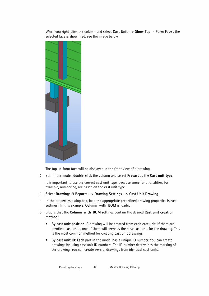
When you right-click the column and select Cast Unit --> Show Top in Form Face , theselected face is shown red, see the image below.
The top-in-form face will be displayed in the front view of a drawing.
2. Still in the model, double-click the column and select Precast as the Cast unit type.
It is important to use the correct cast unit type, because some functionalities, forexample, numbering, are based on the cast unit type.
3. Select Drawings & Reports --> Drawing Settings --> Cast Unit Drawing .
4. In the properties dialog box, load the appropriate predefined drawing properties (savedsettings). In this example, Column_with_BOM is loaded.
5. Ensure that the Column_with_BOM settings contain the desired Cast unit creationmethod:
• By cast unit position: A drawing will be created from each cast unit. If there areidentical cast units, one of them will serve as the base cast unit for the drawing. Thisis the most common method for creating cast unit drawings.
• By cast unit ID: Each part in the model has a unique ID number. You can createdrawings by using cast unit ID numbers. The ID number determines the marking ofthe drawing. You can create several drawings from identical cast units.
Creating drawings 66 Master Drawing Catalog
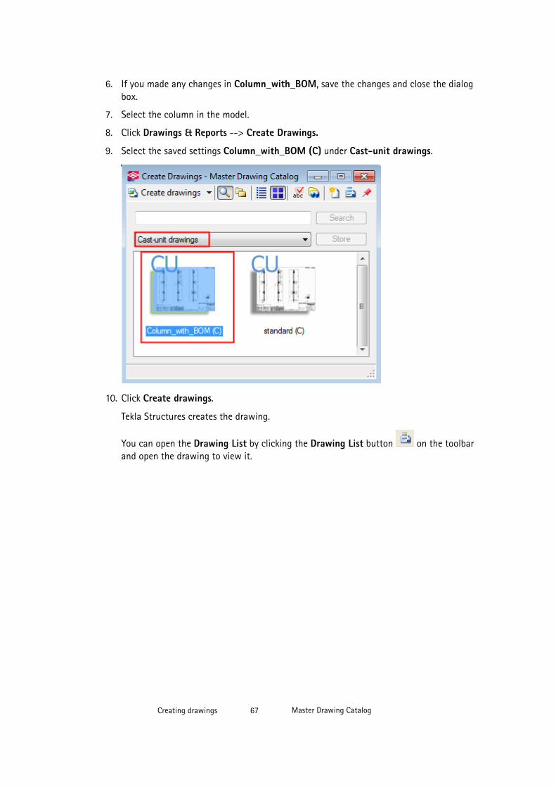
6. If you made any changes in Column_with_BOM, save the changes and close the dialogbox.
7. Select the column in the model.
8. Click Drawings & Reports --> Create Drawings.
9. Select the saved settings Column_with_BOM (C) under Cast-unit drawings.
10. Click Create drawings.
Tekla Structures creates the drawing.
You can open the Drawing List by clicking the Drawing List button on the toolbarand open the drawing to view it.
Creating drawings 67 Master Drawing Catalog

See also
Creating single-part, assembly and cast unit drawings using saved settings in Master DrawingCatalog on page 64
Example: Creating assembly drawings from groups of similar parts
Creating drawings one by one may take a lot of time. You can automate the creation processa bit more by selecting groups of items and then create the drawings. For example, you candefine the needed properties for the beams and then run all the beam drawings at once byusing the Tekla Structures model selection filters. In this example, you are going to use savedsettings named Beam_with_BOM and create assembly drawings from all beams.
To create assembly drawings in groups:
1. Define a selection filter that selects only one type of items, in this case beams.
a. Click Edit --> Selection Filter in the model.
b. Create a selection filter that selects all objects named BEAM and save it using thename BEAM.
Creating drawings 68 Master Drawing Catalog
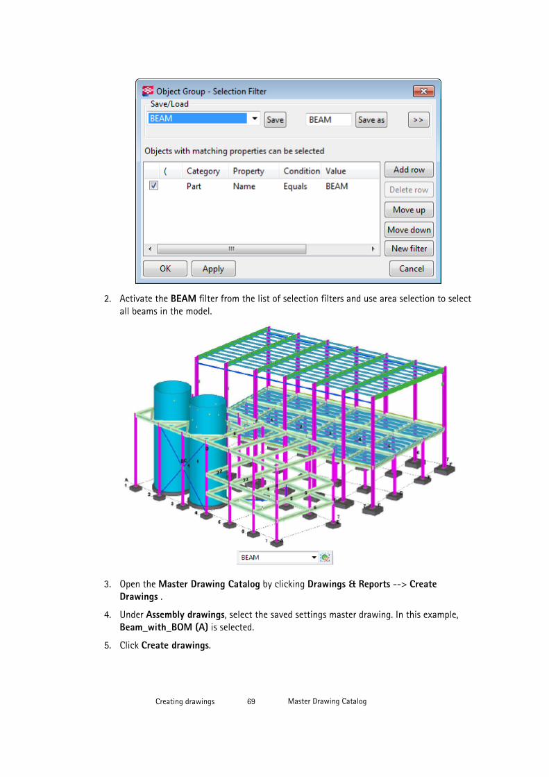
2. Activate the BEAM filter from the list of selection filters and use area selection to selectall beams in the model.
3. Open the Master Drawing Catalog by clicking Drawings & Reports --> CreateDrawings .
4. Under Assembly drawings, select the saved settings master drawing. In this example,Beam_with_BOM (A) is selected.
5. Click Create drawings.
Creating drawings 69 Master Drawing Catalog
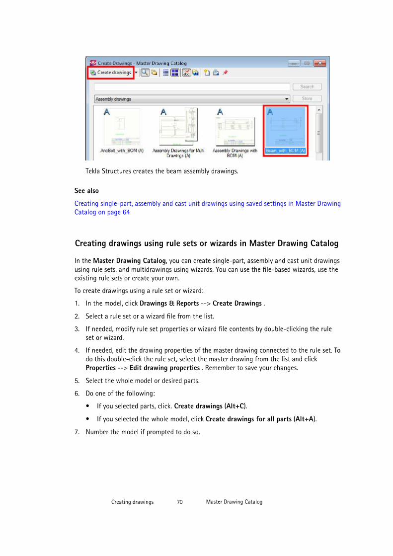
Tekla Structures creates the beam assembly drawings.
See also
Creating single-part, assembly and cast unit drawings using saved settings in Master DrawingCatalog on page 64
Creating drawings using rule sets or wizards in Master Drawing Catalog
In the Master Drawing Catalog, you can create single-part, assembly and cast unit drawingsusing rule sets, and multidrawings using wizards. You can use the file-based wizards, use theexisting rule sets or create your own.
To create drawings using a rule set or wizard:
1. In the model, click Drawings & Reports --> Create Drawings .
2. Select a rule set or a wizard file from the list.
3. If needed, modify rule set properties or wizard file contents by double-clicking the ruleset or wizard.
4. If needed, edit the drawing properties of the master drawing connected to the rule set. Todo this double-click the rule set, select the master drawing from the list and clickProperties --> Edit drawing properties . Remember to save your changes.
5. Select the whole model or desired parts.
6. Do one of the following:
• If you selected parts, click. Create drawings (Alt+C).
• If you selected the whole model, click Create drawings for all parts (Alt+A).
7. Number the model if prompted to do so.
Creating drawings 70 Master Drawing Catalog
Tekla Structures creates the drawings and adds them in the Drawing List. Click the drawinglist icon on the Master Drawing Catalog toolbar to open the Drawing List.
NOTE If you already have a drawing with the same type and mark, Tekla Structures will not create anew one.
Limitations
• In the Master Drawing Catalog, you can create multidrawings only by using the wizards.You cannot create rule sets for multidrawings.
• You cannot create general arrangement drawings in the Master Drawing Catalog usingrule sets or wizards. General arrangement drawings can only be created using savedsettings.
See also
Rule sets on page 57
Wizards on page 58
Master Drawing Catalog on page 52
Adding a rule set on page 80
Example - Creating a new rule set and drawings for all parts on page 71
Example - Creating a new rule set and drawings for all parts
The following example will go through creating a basic rule set that will create assembly andsingle part drawings based on the names of the parts in the model.
The model used here is a very simple model consisting of two columns with a beam inbetween, base plates and end plates. The parts are named BEAM, COLUMN and PLATE.
Before setting up a rule set in the Master Drawing Catalog, you need to have some savedsettings (drawing properties) and some selection filters that link the drawing properties tothe parts in the model.
Creating selection filters
You need to have filters that select the beams, columns and plates.
To create the selection filters:
1. In the model, select Edit --> Selection Filter .
Creating drawings 71 Master Drawing Catalog
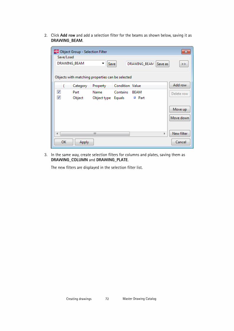
2. Click Add row and add a selection filter for the beams as shown below, saving it asDRAWING_BEAM.
3. In the same way, create selection filters for columns and plates, saving them asDRAWING_COLUMN and DRAWING_PLATE.
The new filters are displayed in the selection filter list.
Creating drawings 72 Master Drawing Catalog
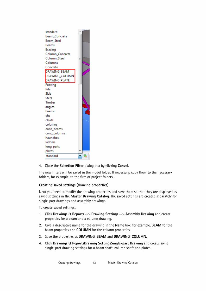
4. Close the Selection Filter dialog box by clicking Cancel.
The new filters will be saved in the model folder. If necessary, copy them to the necessaryfolders, for example, to the firm or project folders.
Creating saved settings (drawing properties)
Next you need to modify the drawing properties and save them so that they are displayed assaved settings in the Master Drawing Catalog. The saved settings are created separately forsingle-part drawings and assembly drawings.
To create saved settings:
1. Click Drawings & Reports --> Drawing Settings --> Assembly Drawing and createproperties for a beam and a column drawing.
2. Give a descriptive name for the drawing in the Name box, for example, BEAM for thebeam properties and COLUMN for the column properties.
3. Save the properties as DRAWING_BEAM and DRAWING_COLUMN.
4. Click Drawings & ReportsDrawing SettingsSingle-part Drawing and create somesingle-part drawing settings for a beam shaft, column shaft and plates.
Creating drawings 73 Master Drawing Catalog
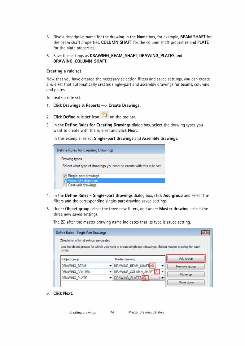
5. Give a descriptive name for the drawing in the Name box, for example, BEAM SHAFT forthe beam shaft properties, COLUMN SHAFT for the column shaft properties and PLATEfor the plate properties.
6. Save the settings as DRAWING_BEAM_SHAFT, DRAWING_PLATES andDRAWING_COLUMN_SHAFT.
Creating a rule set
Now that you have created the necessary selection filters and saved settings, you can createa rule set that automatically creates single-part and assembly drawings for beams, columnsand plates.
To create a rule set:
1. Click Drawings & Reports --> Create Drawings .
2. Click Define rule set icon on the toolbar.
3. In the Define Rules for Creating Drawings dialog box, select the drawing types youwant to create with the rule set and click Next.
In this example, select Single-part drawings and Assembly drawings.
4. In the Define Rules - Single-part Drawings dialog box, click Add group and select thefilters and the corresponding single-part drawing saved settings.
5. Under Object group select the three new filters, and under Master drawing, select thethree new saved settings.
The (S) after the master drawing name indicates that its type is saved setting.
6. Click Next.
Creating drawings 74 Master Drawing Catalog
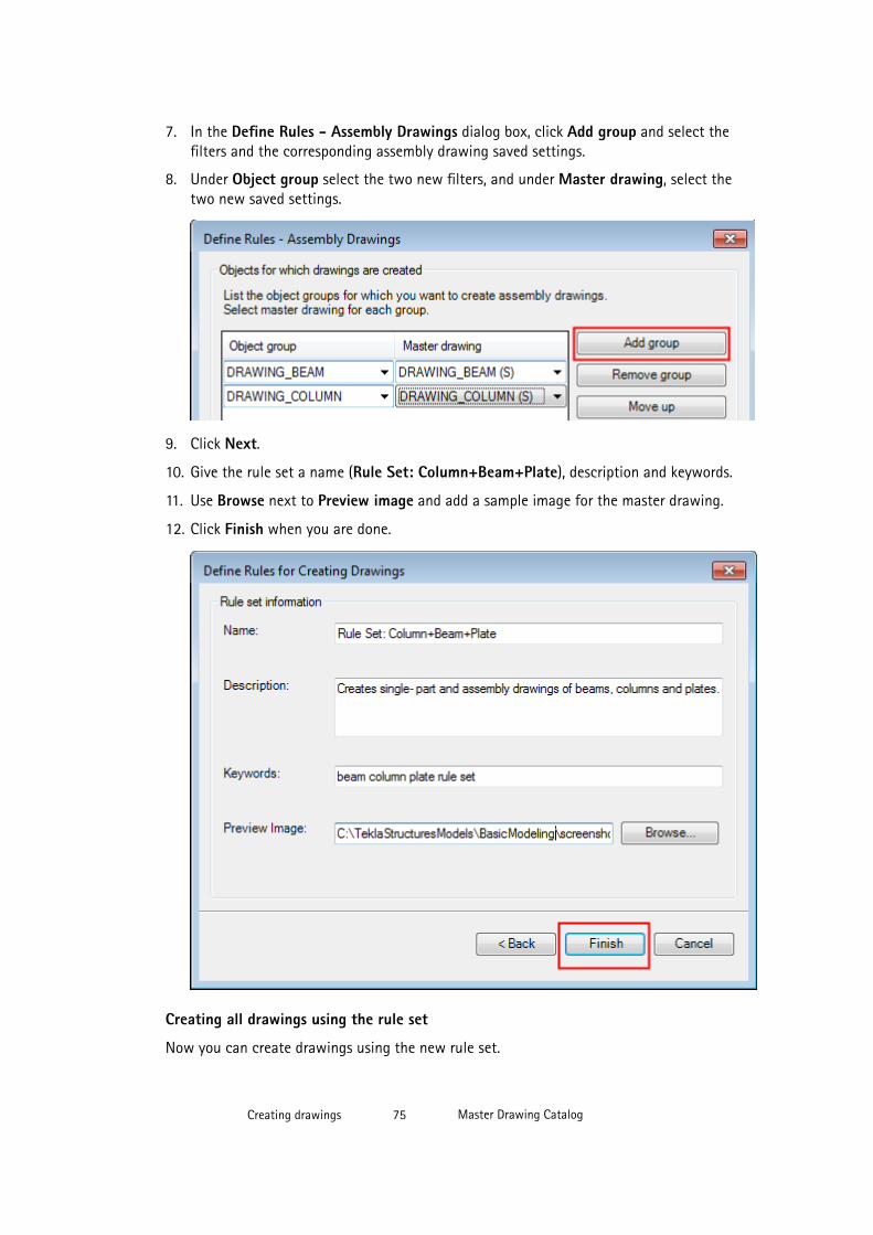
7. In the Define Rules - Assembly Drawings dialog box, click Add group and select thefilters and the corresponding assembly drawing saved settings.
8. Under Object group select the two new filters, and under Master drawing, select thetwo new saved settings.
9. Click Next.
10. Give the rule set a name (Rule Set: Column+Beam+Plate), description and keywords.
11. Use Browse next to Preview image and add a sample image for the master drawing.
12. Click Finish when you are done.
Creating all drawings using the rule set
Now you can create drawings using the new rule set.
Creating drawings 75 Master Drawing Catalog
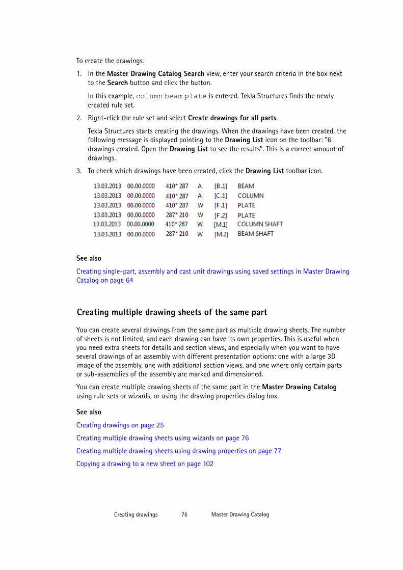
To create the drawings:
1. In the Master Drawing Catalog Search view, enter your search criteria in the box nextto the Search button and click the button.
In this example, column beam plate is entered. Tekla Structures finds the newlycreated rule set.
2. Right-click the rule set and select Create drawings for all parts.
Tekla Structures starts creating the drawings. When the drawings have been created, thefollowing message is displayed pointing to the Drawing List icon on the toolbar: "6drawings created. Open the Drawing List to see the results". This is a correct amount ofdrawings.
3. To check which drawings have been created, click the Drawing List toolbar icon.
See also
Creating single-part, assembly and cast unit drawings using saved settings in Master DrawingCatalog on page 64
Creating multiple drawing sheets of the same part
You can create several drawings from the same part as multiple drawing sheets. The numberof sheets is not limited, and each drawing can have its own properties. This is useful whenyou need extra sheets for details and section views, and especially when you want to haveseveral drawings of an assembly with different presentation options: one with a large 3Dimage of the assembly, one with additional section views, and one where only certain partsor sub-assemblies of the assembly are marked and dimensioned.
You can create multiple drawing sheets of the same part in the Master Drawing Catalogusing rule sets or wizards, or using the drawing properties dialog box.
See also
Creating drawings on page 25
Creating multiple drawing sheets using wizards on page 76
Creating multiple drawing sheets using drawing properties on page 77
Copying a drawing to a new sheet on page 102
Creating drawings 76 Master Drawing Catalog
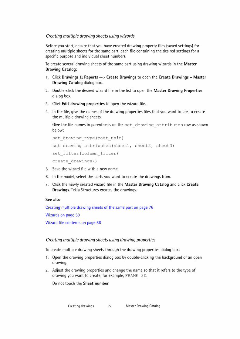
Creating multiple drawing sheets using wizards
Before you start, ensure that you have created drawing property files (saved settings) forcreating multiple sheets for the same part, each file containing the desired settings for aspecific purpose and individual sheet numbers.
To create several drawing sheets of the same part using drawing wizards in the MasterDrawing Catalog:
1. Click Drawings & Reports --> Create Drawings to open the Create Drawings - MasterDrawing Catalog dialog box.
2. Double-click the desired wizard file in the list to open the Master Drawing Propertiesdialog box.
3. Click Edit drawing properties to open the wizard file.
4. In the file, give the names of the drawing properties files that you want to use to createthe multiple drawing sheets.
Give the file names in parenthesis on the set_drawing_attributes row as shownbelow:
set_drawing_type(cast_unit)set_drawing_attributes(sheet1, sheet2, sheet3)set_filter(column_filter)create_drawings()
5. Save the wizard file with a new name.
6. In the model, select the parts you want to create the drawings from.
7. Click the newly created wizard file in the Master Drawing Catalog and click CreateDrawings. Tekla Structures creates the drawings.
See also
Creating multiple drawing sheets of the same part on page 76
Wizards on page 58
Wizard file contents on page 86
Creating multiple drawing sheets using drawing properties
To create multiple drawing sheets through the drawing properties dialog box:
1. Open the drawing properties dialog box by double-clicking the background of an opendrawing.
2. Adjust the drawing properties and change the name so that it refers to the type ofdrawing you want to create, for example, FRAME 3D.
Do not touch the Sheet number.
Creating drawings 77 Master Drawing Catalog
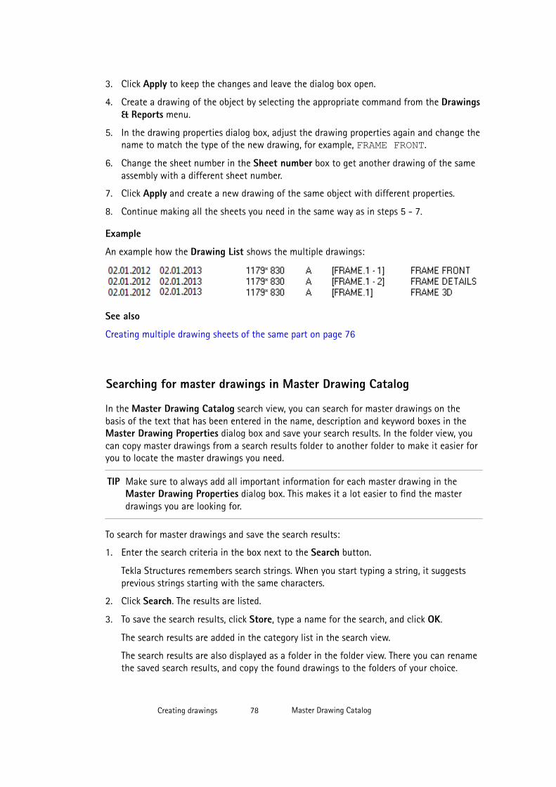
3. Click Apply to keep the changes and leave the dialog box open.
4. Create a drawing of the object by selecting the appropriate command from the Drawings& Reports menu.
5. In the drawing properties dialog box, adjust the drawing properties again and change thename to match the type of the new drawing, for example, FRAME FRONT.
6. Change the sheet number in the Sheet number box to get another drawing of the sameassembly with a different sheet number.
7. Click Apply and create a new drawing of the same object with different properties.
8. Continue making all the sheets you need in the same way as in steps 5 - 7.
Example
An example how the Drawing List shows the multiple drawings:
See also
Creating multiple drawing sheets of the same part on page 76
Searching for master drawings in Master Drawing Catalog
In the Master Drawing Catalog search view, you can search for master drawings on thebasis of the text that has been entered in the name, description and keyword boxes in theMaster Drawing Properties dialog box and save your search results. In the folder view, youcan copy master drawings from a search results folder to another folder to make it easier foryou to locate the master drawings you need.
TIP Make sure to always add all important information for each master drawing in theMaster Drawing Properties dialog box. This makes it a lot easier to find the masterdrawings you are looking for.
To search for master drawings and save the search results:
1. Enter the search criteria in the box next to the Search button.
Tekla Structures remembers search strings. When you start typing a string, it suggestsprevious strings starting with the same characters.
2. Click Search. The results are listed.
3. To save the search results, click Store, type a name for the search, and click OK.
The search results are added in the category list in the search view.
The search results are also displayed as a folder in the folder view. There you can renamethe saved search results, and copy the found drawings to the folders of your choice.
Creating drawings 78 Master Drawing Catalog
See also
Master Drawing Catalog on page 52
Modifying master drawing properties on page 83
Customizing Master Drawing Catalog
You can customize the Master Drawing Catalog according to your needs. Keeping theMaster Drawing Catalog up to date and well organized is essential if you want to createdrawings fast and efficiently. Having good master drawings saves time and effort. Add onlythe necessary master drawings, remove obsolete ones, organize the master drawings infolders, add proper preview images, and keep the properties, descriptions and keywords up todate.
See also
Adding master drawings in Master Drawing Catalog on page 79
Removing master drawings from the Master Drawing Catalog on page 82
Modifying master drawing properties on page 83
Managing Master Drawing Catalog folders on page 88
Adding sample and thumbnail images to master drawings on page 92
Master Drawing Catalog on page 52
Sample images of drawings on page 91
Adding master drawings in Master Drawing Catalog
Depending on your environment, the Master Drawing Catalog usually contains some masterdrawings when you start using it, at least the predefined saved settings (drawing propertyfiles) are displayed there. You can also add new saved settings, rule sets and cloningtemplates.
See also
Adding saved settings on page 79
Adding a rule set on page 80
Adding a cloning template on page 82
Creating drawings 79 Master Drawing Catalog
Adding saved settings
All predefined drawing properties files are shown as saved settings in the Master DrawingCatalog. When you save a new drawing properties file, Tekla Structures shows it in theMaster Drawing Catalog.
To add saved settings to the Master Drawing Catalog:
1. Modify the drawing properties in the Single-part Drawing Properties, Cast UnitDrawing Properties, Assembly Drawing Properties or General Arrangement DrawingProperties dialog box.
2. Give a name to the property file in the box next to the Save as button and click Save as.
The new property file is automatically added to the Master Drawing Catalog. If it is notdisplayed in the list, press F5 to refresh the view.
3. Modify master drawing properties: give the master drawing a name, add a sample image,and enter a description and keywords.
See also
Adding master drawings in Master Drawing Catalog on page 79
Saved settings on page 55
Adding sample and thumbnail images to master drawings on page 92
Creating drawings using saved settings in Master Drawing Catalog on page 58
Adding a rule set
To add a rule set in the Master Drawing Catalog:
1. Click the Add rule set toolbar command button .
2. In the Define Rules for Creating Drawings dialog box, select the drawing types youwant to create with the rule set.
You can select several drawing types with the same rule set. For example, you can usethe same rule set to create single-part drawings and assembly drawings.
3. Click Next.
Creating drawings 80 Master Drawing Catalog
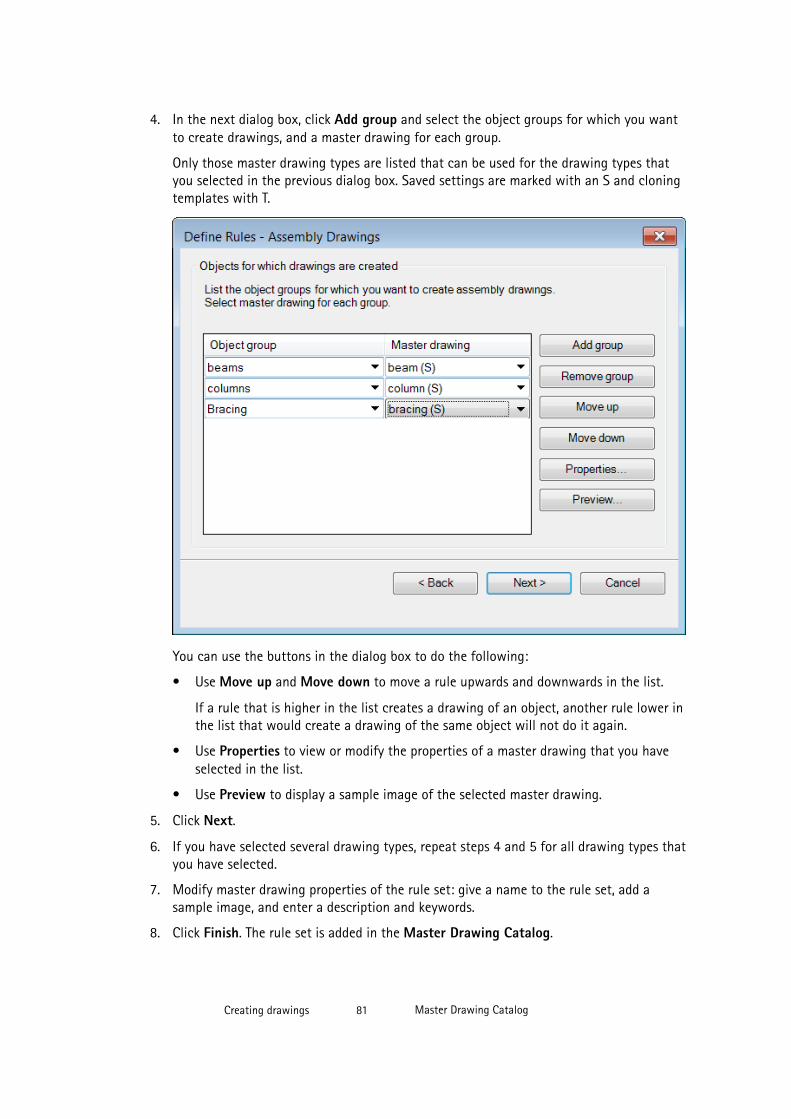
4. In the next dialog box, click Add group and select the object groups for which you wantto create drawings, and a master drawing for each group.
Only those master drawing types are listed that can be used for the drawing types thatyou selected in the previous dialog box. Saved settings are marked with an S and cloningtemplates with T.
You can use the buttons in the dialog box to do the following:
• Use Move up and Move down to move a rule upwards and downwards in the list.
If a rule that is higher in the list creates a drawing of an object, another rule lower inthe list that would create a drawing of the same object will not do it again.
• Use Properties to view or modify the properties of a master drawing that you haveselected in the list.
• Use Preview to display a sample image of the selected master drawing.
5. Click Next.
6. If you have selected several drawing types, repeat steps 4 and 5 for all drawing types thatyou have selected.
7. Modify master drawing properties of the rule set: give a name to the rule set, add asample image, and enter a description and keywords.
8. Click Finish. The rule set is added in the Master Drawing Catalog.
Creating drawings 81 Master Drawing Catalog

See also
Adding master drawings in Master Drawing Catalog on page 79
Rule sets on page 57
Creating drawings using rule sets or wizards in Master Drawing Catalog on page 70
Adding sample and thumbnail images to master drawings on page 92
Example - Creating a new rule set and drawings for all parts on page 71
Adding a cloning template
You can add drawings in the Master Drawing Catalog from the Drawing List.
Before you add a cloning template in the Master Drawing Catalog, create a drawing withthe desired properties and contents and save it.
Limitations: You cannot add general arrangement drawings or multidrawings to the MasterDrawing Catalog from the Drawing List. You can clone general arrangement drawings usingthe Clone command in the Drawing List dialog box.
To add a new cloning template:
1. Open the Drawing List by clicking Drawings & Reports --> Drawing List .
2. Select the drawing, right-click and select Add to Master Drawing Catalog (Ctrl + M).
3. Modify the master drawing properties of the cloning template. On the General tab, entera name for the cloning template, and a short description and keywords.
4. Tekla Structures adds a preliminary thumbnail image for the cloning template. Ifnecessary, click Change Image and browse for a new image. The same image will then bedisplayed when you right-click the thumbnail and select Preview.
5. Go to the Drawing creation tab and specify how dimensions and marks are created, andselect the objects to be cloned from the master drawing.
6. Click OK.
The new cloning template is added in the Master Drawing Catalog. The icon isdisplayed in the Master column of the Drawing List next to the drawing you added.
See also
Adding master drawings in Master Drawing Catalog on page 79
Cloning templates on page 54
Creating drawings using cloning templates in Master Drawing Catalog on page 94
Adding sample and thumbnail images to master drawings on page 92
Creating drawings 82 Master Drawing Catalog
Removing master drawings from the Master Drawing Catalog
Limitations: In the folder view, you cannot remove master drawings from the MasterDrawing Catalog through the folders that you have created yourself. Use the Saved searchesfolders to display the desired master drawings and then remove the extra ones.
To remove master drawings from the Master Drawing Catalog:
1. In the Master Drawing Catalog, select the master drawings you want to remove.
2. Right-click and select Remove from Catalog.
3. Confirm the removal.
Tekla Structures removes the master drawing(s) from the catalog. Any created drawingsthat are based on removed master drawings remain in the Drawing List. The catalogproperties that you have entered for the master drawing are not deleted. They are stillavailable for the master drawing if you decide to add the master drawing back to thecatalog.
See also
Customizing Master Drawing Catalog on page 79
Modifying master drawing properties
Each master drawing in the Master Drawing Catalog has its own properties. You can searchfor master drawings based on the master drawing name, description and keywords. A sampleimage can also be added for each master drawing (Change image button). The sample imageis also shown as a thumbnail in the thumbnail view of the Master Drawing Catalog. You canaccess drawing properties (Edit drawing properties button) and you can, for example, applyobject level settings.
TIP Make sure to always add all important information for each master drawing in theMaster Drawing Properties dialog box. This makes it a lot easier to find the masterdrawings you are looking for.
Creating drawings 83 Master Drawing Catalog
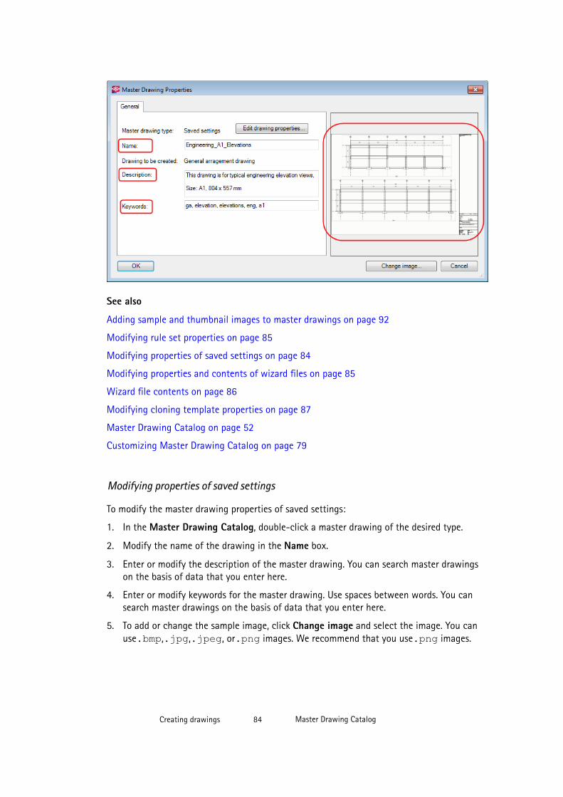
See also
Adding sample and thumbnail images to master drawings on page 92
Modifying rule set properties on page 85
Modifying properties of saved settings on page 84
Modifying properties and contents of wizard files on page 85
Wizard file contents on page 86
Modifying cloning template properties on page 87
Master Drawing Catalog on page 52
Customizing Master Drawing Catalog on page 79
Modifying properties of saved settings
To modify the master drawing properties of saved settings:
1. In the Master Drawing Catalog, double-click a master drawing of the desired type.
2. Modify the name of the drawing in the Name box.
3. Enter or modify the description of the master drawing. You can search master drawingson the basis of data that you enter here.
4. Enter or modify keywords for the master drawing. Use spaces between words. You cansearch master drawings on the basis of data that you enter here.
5. To add or change the sample image, click Change image and select the image. You canuse.bmp,.jpg,.jpeg, or.png images. We recommend that you use.png images.
Creating drawings 84 Master Drawing Catalog
6. If needed, modify the drawing properties of the master drawing by clicking Edit drawingproperties... to display the drawing properties dialog box. This also allows you to applyobject level settings.
Edit the properties and save them. Ensure that you have the correct drawing property filename at the top.
7. Click OK.
See also
Modifying master drawing properties on page 83
Applying detailed object level settings in saved settings on page 58
Saved settings on page 55
Modifying rule set properties
To modify the master drawing properties of rule sets:
1. In the Master Drawing Catalog, double-click a master drawing of the desired type.
2. In the Edit Rules dialog box, modify the drawing type selections if necessary.
3. Click Next.
4. Add or remove object groups and select the appropriate master drawing type.
5. Click Next and do the same for all the selected drawing types.
6. Modify the name of the drawing in the Name box.
7. Enter or modify the description of the master drawing.
You can search for master drawings based on the data you enter here.
8. Enter of modify keywords of the master drawing.
Use spaces between words. You can search master drawings on the basis of data youenter here.
9. To add or change the sample image, click Change image and select the image.
You can use .bmp, .jpg, .jpeg, or .png images. We recommend that you use .pngimages.
The same image is used in the thumbnail view of the Master Drawing Catalog.
10. Click Save to save your changes.
See also
Modifying master drawing properties on page 83
Rule sets on page 57
Creating drawings 85 Master Drawing Catalog
Modifying properties and contents of wizard files
You can modify wizard files using a text editor through the Master Drawing Propertiesdialog box. In previous versions of Tekla Structures, you could only edit and use wizard filesthrough the AutoDrawings dialog box.
To modify the master drawing properties of wizard files and the wizard file contents:
1. In the Master Drawing Catalog, double-click a wizard file.
2. Modify the name of the drawing in the Name box.
3. Enter or modify the description of the master drawing.
You can search for master drawings based on the data you enter here.
4. Enter of modify keywords of the master drawing.
Use spaces between words. You can search for master drawings based on the data youenter here.
5. To add or change the sample image, click Change image and select the image.
You can use .bmp, .jpg, .jpeg, or .png images. We recommend that you use .pngimages.
The sample image will also be used as the thumbnail image of the master drawing in thethumbnail view of the Master Drawing Catalog.
6. To edit the contents of the wizard file, click Edit drawing properties.
The wizard file is opened in a text editor. Modify the contents of the file, and save andclose it.
7. Click OK.
See also
Modifying master drawing properties on page 83
Wizards on page 58
Wizard file contents
Wizard files consist of the following entries. Notice the use of parentheses.
set_drawing_type(assembly)This line defines the type of drawing the wizard creates. The drawing type appears inparentheses. The options are:
Option Creates
single single-part drawings
assembly assembly drawings
multi_single single-part multidrawings
Creating drawings 86 Master Drawing Catalog

Option Creates
multi_single_with_layout single-part multidrawings with layout
multi_assembly assembly multidrawings
multi_assembly_with_layout assembly multidrawings with layout
cast_unit cast unit drawings
set_drawing_attributes(column)This line tells Tekla Structures which drawing properties to use when creating the drawings.The name of the saved drawing properties appears in parentheses.
set_template_drawingThis line tells Tekla Structures to use the defined drawing as a template when creating a newdrawing. This line is used instead of the line set_drawing_attributes. The path andthe name of the drawing template are given in parenthesis like in the following example: set_template_drawing("C:\TSModels\AngleModel":"[A.2]")set_filter(column_filter)This line tells Tekla Structures which selection filter to use to select the parts from which tocreate drawings. The filter name appears in parentheses.
create_drawings()Tekla Structures starts creating the drawings. This line should always appear immediatelyafter the lines set_drawing_type, set_drawing_attributes and set_filter.
See also
Wizards on page 58
Creating drawings using rule sets or wizards in Master Drawing Catalog on page 70
Modifying properties and contents of wizard files on page 85
Modifying cloning template properties
To modify the master drawing properties of cloning templates:
1. In the Master Drawing Catalog, double-click a master drawing of the desired type.
2. Modify the name of the drawing in the Name box.
3. Enter or modify the description of the master drawing.
You can search for master drawings based on the data you enter here.
4. Enter of modify keywords of the master drawing.
Use spaces between words. You can search for master drawings based on the data youenter here.
5. To add or change the sample image, click Change image and select the image.
Creating drawings 87 Master Drawing Catalog
You can use .bmp, .jpg, .jpeg, or .png images. We recommend that you use .pngimages.
The sample image will also be used as the thumbnail image of the master drawing in thethumbnail view of the Master Drawing Catalog.
6. Go to the Drawing creation tab.
a. For the Dimensions, Marks, and Marks for welds in model, define whether you wantto Clone them, recreate them automatically when you clone a drawing (Create) orIgnore them in cloning.
b. Select the objects to be cloned from the master drawing: Drawing welds, Levelmarks, DWG/DXF, Text files, Texts, Symbols, Graphics, and Hyperlinks).
7. Click OK.
See also
Modifying master drawing properties on page 83
Cloning templates on page 54
Creating drawings using cloning templates in Master Drawing Catalog on page 94
Managing Master Drawing Catalog folders
In the folder view of the Master Drawing Catalog you can manage the folders in thefollowing ways:
• Add new, rename, and delete folders
• Copy master drawings to another folder
• Delete master drawings from folders
• Change the folder location in the tree
Creating drawings 88 Master Drawing Catalog
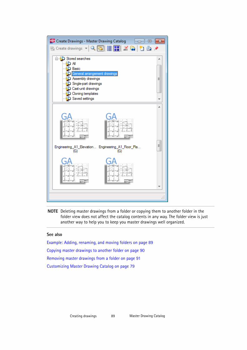
NOTE Deleting master drawings from a folder or copying them to another folder in thefolder view does not affect the catalog contents in any way. The folder view is justanother way to help you to keep you master drawings well organized.
See also
Example: Adding, renaming, and moving folders on page 89
Copying master drawings to another folder on page 90
Removing master drawings from a folder on page 91
Customizing Master Drawing Catalog on page 79
Creating drawings 89 Master Drawing Catalog
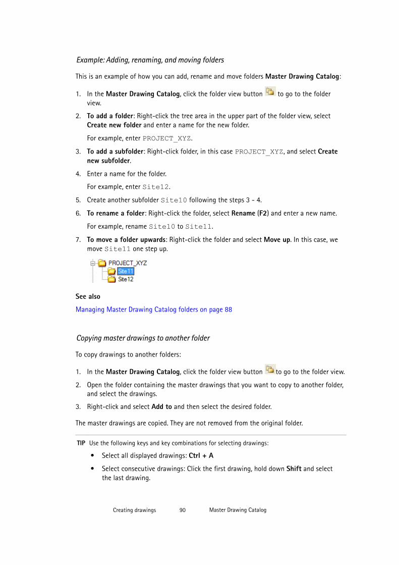
Example: Adding, renaming, and moving folders
This is an example of how you can add, rename and move folders Master Drawing Catalog:
1. In the Master Drawing Catalog, click the folder view button to go to the folderview.
2. To add a folder: Right-click the tree area in the upper part of the folder view, selectCreate new folder and enter a name for the new folder.
For example, enter PROJECT_XYZ.
3. To add a subfolder: Right-click folder, in this case PROJECT_XYZ, and select Createnew subfolder.
4. Enter a name for the folder.
For example, enter Site12.
5. Create another subfolder Site10 following the steps 3 - 4.
6. To rename a folder: Right-click the folder, select Rename (F2) and enter a new name.
For example, rename Site10 to Site11.
7. To move a folder upwards: Right-click the folder and select Move up. In this case, wemove Site11 one step up.
See also
Managing Master Drawing Catalog folders on page 88
Copying master drawings to another folder
To copy drawings to another folders:
1. In the Master Drawing Catalog, click the folder view button to go to the folder view.
2. Open the folder containing the master drawings that you want to copy to another folder,and select the drawings.
3. Right-click and select Add to and then select the desired folder.
The master drawings are copied. They are not removed from the original folder.
TIP Use the following keys and key combinations for selecting drawings:
• Select all displayed drawings: Ctrl + A
• Select consecutive drawings: Click the first drawing, hold down Shift and selectthe last drawing.
Creating drawings 90 Master Drawing Catalog
• Select several drawings: Click the first drawing, hold down Ctrl and select the restof the drawings.
See also
Managing Master Drawing Catalog folders on page 88
Removing master drawings from a folder
You may want to remove master drawings from a folder in the folder view, for example, whenyou have added the master drawings in another folder and do not need them in the originalfolder anymore.
To remove drawings from a folder:
1. In the Master Drawing Catalog, click the folder view button to go to the folder view.
2. In the upper part of the folder view, click the folder from which you want to removedrawings.
The master drawings in the folder are shown in the lower part of the view.
3. Select the master drawings to be deleted, right-click and select Remove from folder.
The master drawings are removed from the folder. The master drawings are not removed fromthe catalog, just from the folder.
See also
Managing Master Drawing Catalog folders on page 88
Sample images of drawings
You can create sample or preview images of the drawings. These screenshots are saved bydefault in the \drawings folder under the model folder as .png files.
The sample images can be viewed by selecting Preview from the master drawing's pop-upmenu. They can also be used as thumbnail images for master drawings in the MasterDrawing Catalog views. They can also be viewed through the Clone Drawings dialog box,when you start cloning from the Drawing List.
See also
Creating sample images on page 91
Adding sample and thumbnail images to master drawings on page 92
Viewing sample images of drawing templates on page 93
Creating drawings 91 Master Drawing Catalog
Creating sample images
You may want to add a sample image for a master drawing in the Master Drawing Catalog.Before you can create a sample image of a drawing, you must first create the drawing.
To create a sample image:
1. Open the drawing you want to use.
2. Clean up the drawing from unnecessary objects, for example, associativity symbols.
3. Click Tools > Create Preview Image.
The image is saved in the \drawings folder under the model folder in .png formatwith the same name as the drawing.
See also
Sample images of drawings on page 91
Adding sample and thumbnail images to master drawings
Before you can add a sample image or a preview image to a master drawing, you must haveit somewhere ready.
The same image that you add as a sample image is used as the thumbnail image for theparticular master drawing in the Master Drawing Catalog.
NOTE Sample images are just samples, they are not real drawings, and they do not updatewhen the drawing changes.
To add a sample and thumbnail image to a master drawing in the Master Drawing Catalog:
1. Open the Master Drawing Catalog by clicking Drawings & Reports --> CreateDrawings .
2. Locate the desired master drawing and double-click it to open the Master DrawingProperties dialog box.
3. Add the image you created:
• For the master drawings of the type saved settings, cloning templates, and wizardfiles, click Change image and browse for the preview image. Click OK to save theimage as a sample image.
• For rule sets, click Next until you get to the page where you can add the previewimage. Click Browse and browse for the preview image. Click Save to save the imageas a sample image.
Now you can display the sample image by selecting the master drawing on the cataloglist, right-clicking and selecting Preview. The thumbnail image in the Master DrawingCatalog thumbnail view is a smaller version of the same sample image.
Creating drawings 92 Master Drawing Catalog
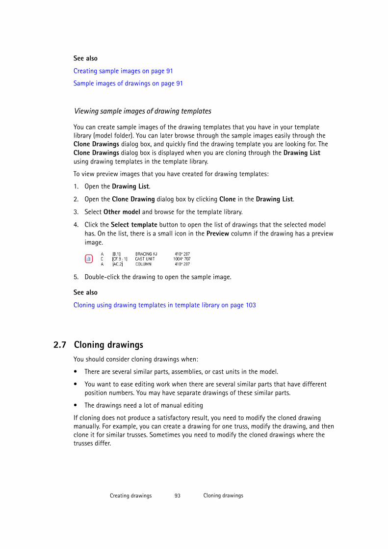
See also
Creating sample images on page 91
Sample images of drawings on page 91
Viewing sample images of drawing templates
You can create sample images of the drawing templates that you have in your templatelibrary (model folder). You can later browse through the sample images easily through theClone Drawings dialog box, and quickly find the drawing template you are looking for. TheClone Drawings dialog box is displayed when you are cloning through the Drawing Listusing drawing templates in the template library.
To view preview images that you have created for drawing templates:
1. Open the Drawing List.
2. Open the Clone Drawing dialog box by clicking Clone in the Drawing List.
3. Select Other model and browse for the template library.
4. Click the Select template button to open the list of drawings that the selected modelhas. On the list, there is a small icon in the Preview column if the drawing has a previewimage.
5. Double-click the drawing to open the sample image.
See also
Cloning using drawing templates in template library on page 103
2.7 Cloning drawingsYou should consider cloning drawings when:
• There are several similar parts, assemblies, or cast units in the model.
• You want to ease editing work when there are several similar parts that have differentposition numbers. You may have separate drawings of these similar parts.
• The drawings need a lot of manual editing
If cloning does not produce a satisfactory result, you need to modify the cloned drawingmanually. For example, you can create a drawing for one truss, modify the drawing, and thenclone it for similar trusses. Sometimes you need to modify the cloned drawings where thetrusses differ.
Creating drawings 93 Cloning drawings
The cloned drawing may contain more or less parts than the original drawing. Part properties,marks, associative notes and related text objects are cloned from a similar part in the originaldrawing.
You can clone drawings using the cloning templates added in the Master Drawing Catalogin the existing model and in other models, using a drawing in the Drawing List, and usingthe cloning templates in the template library.
See also
Creating drawings using cloning templates in Master Drawing Catalog on page 94
Cloning by using cloning templates located in other models on page 95
Cloning from the Drawing List on page 96
View-specific dimension cloning on page 99
Cloning using drawing templates in template library on page 103
Cloned objects on page 100
Checking and modifying cloned drawings on page 101
Refreshing drawing associativity on page 101
Creating drawings on page 25
Creating drawings using cloning templates in Master Drawing Catalog
In the Master Drawing Catalog, you can create single-part, assembly and cast unit drawingsusing cloning templates in the Master Drawing Catalog. You can add new cloning templatesfrom the Drawing List. Note that only the cloning templates located in the folder that is setfor the advanced option XS_CLONING_TEMPLATE_DIRECTORY are displayed in theMaster Drawing Catalog.
Limitations:
• You cannot clone general arrangement drawings through the Master Drawing Catalog.You can clone general arrangement drawings only by using the Clone command in theDrawing List dialog box.
• You cannot clone multidrawings.
• The drawing properties of cloning templates cannot be modified through the MasterDrawing Catalog.
To create drawings using a cloning template:
1. In the model, click Drawings & Reports --> Create Drawings .
2. Double-click the cloning template that you want to use.
3. Go to the Drawing creation tab and specify how dimensions and marks are cloned.
Creating drawings 94 Cloning drawings
You can select to ignore the dimensions and marks, clone them, or recreate them.
The Marks option controls revision marks and all marks for model objects.
TIP Selecting Create in the Dimensions and Other marks box is useful if cloning thedimensions or other marks does not produce satisfactory results. Using this optiondoes not create any new views.
4. On the same tab, select which object types you want to clone.
5. If you want to create a drawing only for certain parts, select the parts from the model.
You can also use an appropriate selection filter and select the whole model. Activate onlythe Select parts selection switch when you select objects, otherwise the selection maytake a long time.
6. Click Create drawings (Alt + C) or Create drawings for all parts (Alt + A).
7. Number the model if prompted to do so.
Tekla Structures creates the drawings and adds them in the Drawing List. In the DrawingList, cloned drawings are marked with text Cloned in the Changes column.
8. Check the cloned drawing and modify it, if necessary.
TIP If you have cloning templates that you have created using an older Tekla Structures version andwant to utilize the better associativity of a newer Tekla Structures version, refresh the drawingassociativity by using the Refresh Associativity command, which you can add to the User menuin the Customize dialog box ( Tools --> Customize ).
See also
Cloning drawings on page 93
Cloned objects on page 100
Checking and modifying cloned drawings on page 101
Refreshing drawing associativity on page 101
Cloning templates on page 54
Adding a cloning template on page 82
XS_CLONING_TEMPLATE_DIRECTORY
XS_INTELLIGENT_CLONING_ADD_DIMENSIONS
Creating drawings 95 Cloning drawings
Cloning by using cloning templates located in other models
You can show cloning templates located in other models in the Master Drawing Catalog andcreate drawings using them.
Limitations: You can use only cloning templates from other models, not other types of masterdrawings, such as saved settings or rule sets.
To use cloning templates from other models:
1. In the Master Drawing Catalog, click to open the Models Containing MasterDrawings dialog box.
2. Click Add model and browse to the desired model.
3. Click OK.
4. Select the cloning template from the Master Drawing Catalog and create a drawingusing the selected template.
TIP When you have similar parts in several projects, you can maintain a set of cloning models andthen take the cloning templates in the cloning models in use when necessary.
See also
Master Drawing Catalog on page 52
Creating drawings using cloning templates in Master Drawing Catalog on page 94
Cloning from the Drawing List
In addition to cloning drawings using cloning templates in Master Drawing Catalog, you canclone single-part, cast unit, assembly and general arrangement drawings from the DrawingList.
NOTE • When you clone drawings of assemblies or cast units, they must have the sametype of main part as the assembly or cast unit from which the original drawingwas created. For example, the upper chords of the original and the cloned trusscould be main parts.
• Section and detail views are not cloned in general arrangement drawings, andonly one view is cloned.
Before cloning, finalize, save, and close the drawing you want to use as a cloning template.
To clone a drawing from the Drawing List:
1. In the model, select what to include in the drawing:
• If you are cloning a single-part drawings, cast unit drawing or assembly drawing,select parts, assemblies or cast units.
Creating drawings 96 Cloning drawings

• If you are cloning a general arrangement drawing, select a model view. To do this,click the desired model view so that the view gets a red frame around it.
2. Click Drawings & Reports > Drawing List.
3. In the Drawing List, select the drawing that you want to use as a cloning template.
4. Click Clone.
5. In the Clone Drawing dialog box, select the drawing object types you want to clone intothe new drawing, and the actions for each object type.
• For Dimensions and Other marks (all marks for model objects), select whether youwant to Clone them, recreate them automatically when you clone a drawing (Create)or Ignore them in cloning.
Selecting Create in the Dimensions and Other marks box is useful if cloning thedimensions or other marks does not produce satisfactory results. Using this optiondoes not create any new views.
• For other objects, select to Clone or Ignore them.
6. Click Clone selected.
Tekla Structures clones the drawing. In the Drawing List, cloned drawings are marked withtext Cloned in the Changes column.
See also
Cloning drawings on page 93
Creating drawings 97 Cloning drawings

Example: Cloning a general arrangement drawing on page 98
Creating drawings using cloning templates in Master Drawing Catalog on page 94
Example: Cloning a general arrangement drawing
In this example, we first created a general arrangement drawing of the first floor of abuilding, then edited the drawing and the cloned the general arrangement drawing of thesecond floor.
The first floor and second floor have some differences:
We edited the general arrangement drawing of the first floor slightly.
Creating drawings 98 Cloning drawings
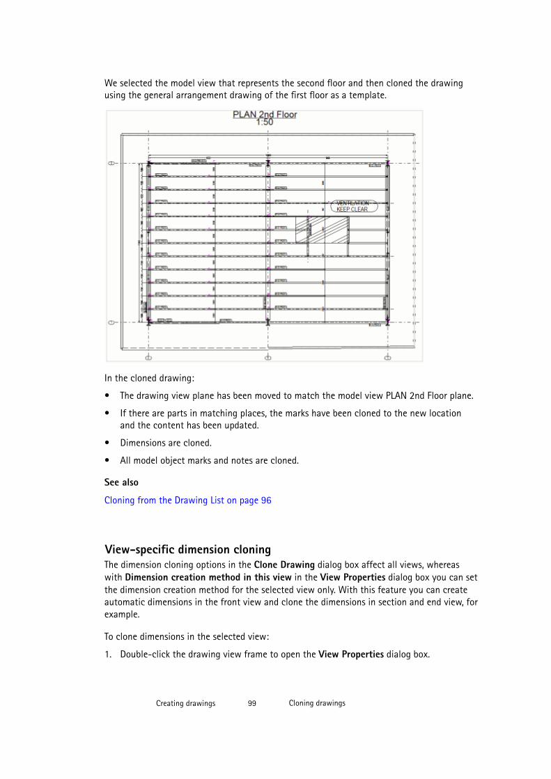
We selected the model view that represents the second floor and then cloned the drawingusing the general arrangement drawing of the first floor as a template.
In the cloned drawing:
• The drawing view plane has been moved to match the model view PLAN 2nd Floor plane.
• If there are parts in matching places, the marks have been cloned to the new locationand the content has been updated.
• Dimensions are cloned.
• All model object marks and notes are cloned.
See also
Cloning from the Drawing List on page 96
View-specific dimension cloningThe dimension cloning options in the Clone Drawing dialog box affect all views, whereaswith Dimension creation method in this view in the View Properties dialog box you can setthe dimension creation method for the selected view only. With this feature you can createautomatic dimensions in the front view and clone the dimensions in section and end view, forexample.
To clone dimensions in the selected view:
1. Double-click the drawing view frame to open the View Properties dialog box.
Creating drawings 99 Cloning drawings
2. Select Dimension creation method in this view --> Clone on the Attributes 2 tab.
3. Click Modify.
4. Save and close the drawing.
5. Open the Drawing List, select the drawing and click Clone.
6. In the Clone Drawing dialog box, select the objects to be cloned and the dimensioncloning option (Ignore, Clone, Create).
• If you select Dimension > Ignore, the dimensions will be cloned only for those viewsthat have Dimension creation method in this view set to Clone.
• If you select Dimension > Clone, the dimensions will be cloned for all views.
• If you select Dimension > Create, the dimensions will be created for all views exceptfor those that have Dimension creation method in this view set to Do not create.
7. Click Clone selected.
See also
Cloning drawings on page 93
Cloned objectsThe following objects can be cloned:
• Dimensions
• Marks for welds added in the drawing
• Marks for welds added in the model
• Level marks
• Revision marks
• Annotation objects
• All user-defined attributes of a drawing
• Texts
• Symbols
• Graphical drawing objects (shapes)
• Text files
• DWG/DXF files
• Hyperlinks
• Manually created section and detail views
• When you clone an assembly drawing that includes single-part drawings, TeklaStructures includes the single-part drawings in the cloned assembly drawing by default.
Creating drawings 100 Cloning drawings

See also
Cloning drawings on page 93
Checking and modifying cloned drawingsAlways check the cloned drawing to make sure that the drawing contents meet your needs.
You should go through the cloned drawings and check that everything is correct. Below is achecklist for this purpose.
Object Check and modify
Marks • In general, mark contents are correct in cloned drawings, butsometimes you may need to modify the location of the marks.
• Tekla Structures clones only marks that can be mapped to theoriginal drawing. To create marks to a cloned drawing also forparts that could not be mapped to the template drawing, set theadvanced option XS_CREATE_MISSING_MARKS_IN_INTELLIGENT_CLONING to TRUE through Tools > Options > Advanced Options>Marking: General.
Views • Ensure that the view sizes and view orientation are correct, andthat the views are placed correctly in the cloned drawing. The sizeof the views is updated according to the parts included in theviews.
Dimensions • If the cloned drawing contains less parts than the originaldrawing, the dimensions to the missing parts are automaticallyremoved.
• If the cloned drawing contains more parts than the originaldrawing, Tekla Structures dimensions the additional parts usingautomatic dimensioning, if you have set the advanced option XS_INTELLIGENT_CLONING_ADD_DIMENSIONS to TRUE.Because Tekla Structures uses automatic dimensioning for creatingdimensions for new parts, you may have to check and correct thecreated dimensions.
• Add missing dimensions and remove the incorrect ones.
See also
Cloning drawings on page 93
Cloned objects on page 100
Creating drawings 101 Cloning drawings
Refreshing drawing associativity
Often improvements in cloning and associativity require that the associative rules have to berecreated. This can be done by using the Refresh Associativity command. When you use thiscommand, you do not need to recreate the drawing.
For example, this command is very useful if you have a cloning template you have createdusing an older Tekla Structures version and want to utilize the better associativity of a newerTekla Structures version.
Refresh Associativity is available in the Customize dialog box, and you may want to add itin one of the toolbars or in the User menu.
To add the command in the User menu and refresh the associativity:
1. Click Tools --> Customize... .
2. Enter a part of the command name in the Filter box, for example, refr.
The command is displayed in the list of commands.
3. Open the Menu tab.
4. Double-click the Refresh Associativity command to add it in the User menu.
5. If you have not added the User menu on the menu bar before, restart Tekla Structures toactivate the menu. The menu name is always User.
6. Open a cloning template the associativity of which you want to refresh from theDrawing List.
7. Click User --> Refresh Associativity .
8. Save the cloning template.
See also
Drawing associativity on page 20
Cloning drawings on page 93
Copying a drawing to a new sheet
You can copy a drawing to a new sheet. This is useful, for example, if you want to have thesame layout and views as in the original drawing, but highlight something else on the newdrawing sheet.
To copy a drawing to a new sheet:
1. In the Drawing List, select the drawing that you want to use as the original for copying.
2. Right-click and select Create Drawings --> Copy to new sheet .
Creating drawings 102 Cloning drawings
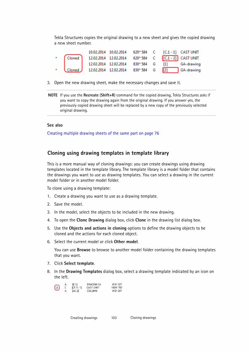
Tekla Structures copies the original drawing to a new sheet and gives the copied drawinga new sheet number.
3. Open the new drawing sheet, make the necessary changes and save it.
NOTE If you use the Recreate (Shift+R) command for the copied drawing, Tekla Structures asks ifyou want to copy the drawing again from the original drawing. If you answer yes, thepreviously copied drawing sheet will be replaced by a new copy of the previously selectedoriginal drawing.
See also
Creating multiple drawing sheets of the same part on page 76
Cloning using drawing templates in template library
This is a more manual way of cloning drawings: you can create drawings using drawingtemplates located in the template library. The template library is a model folder that containsthe drawings you want to use as drawing templates. You can select a drawing in the currentmodel folder or in another model folder.
To clone using a drawing template:
1. Create a drawing you want to use as a drawing template.
2. Save the model.
3. In the model, select the objects to be included in the new drawing.
4. To open the Clone Drawing dialog box, click Clone in the drawing list dialog box.
5. Use the Objects and actions in cloning options to define the drawing objects to becloned and the actions for each cloned object.
6. Select the current model or click Other model.
You can use Browse to browse to another model folder containing the drawing templatesthat you want.
7. Click Select template.
8. In the Drawing Templates dialog box, select a drawing template indicated by an icon onthe left.
Creating drawings 103 Cloning drawings

9. Leave the list open and clone the drawing by clicking Clone selected.
Tekla Structures clones the drawing. In the Drawing List, cloned drawings are marked withtext Cloned in the Changes column.
TIP You can specify that a certain model folder is always used as a template library usingthe advanced option XS_DRAWING_TEMPLATES_LIBRARY.
See also
XS_DRAWING_TEMPLATES_LIBRARY
Cloning drawings on page 93
Creating drawings 104 Cloning drawings

3 Finding and opening drawings
All drawings in a Tekla Structures model are displayed in the Drawing List dialog box. Youcan search, sort, select, and display drawings according to different criteria, and open thedrawings displayed in the list. You can take snapshots of the drawings, and locate thedrawing parts in the model, and to find out if a part is included in any of the drawings.
See also
Opening the Drawing List on page 106
What is displayed in the Drawing List on page 106
Drawing status flags on page 109
Modifying Drawing List contents on page 110
Searching drawings and saving the search results on page 111
Selecting drawings in the Drawing List on page 112
Finding and opening drawings 105 Cloning drawings
Checking whether parts have drawings on page 112
Opening drawings from the model on page 113
Opening a new drawing when a drawing is already open on page 113
Working with drawings on page 282
Creating and viewing drawing snapshots on page 114
3.1 Opening the Drawing List
To open the Drawing List dialog box, do one of the following:
• Click the Open Drawing List button .
• In the model, select Drawings & Reports > Drawing List (Ctrl + L).
• In an open drawing, select Drawing File > Open (Ctrl + O).
See also
Working with drawings on page 282
Finding and opening drawings on page 105
Opening drawings from the model on page 113
Opening a new drawing when a drawing is already open on page 113
3.2 What is displayed in the Drawing List
The Drawing List contains the following columns.
Option Description For more information
Issue, Lock, Freeze,Master, and Up to date
These columns containflags that are graphicalsymbols indicating thedrawing status.
Locking and unlocking drawings onpage 283
Changes Textual informationabout the changes in thedrawing. For example, ifthe drawing has beencloned, it says Cloned inthis column.
Created The creation date of thedrawing.
Finding and opening drawings 106 Opening the Drawing List
Option Description For more informationModified The latest modification
date of the drawing.
Revision The revision number orrevision mark of thedrawing.
By default, TeklaStructures showsrevision numbers. Toshow revision marksinstead, set theadvanced option XS_SHOW_REVISION_MARK_ON_DRAWING_LIST to TRUE.
Revising drawings on page 287
Type The drawing types areidentified by thefollowing letters:
• W for single-partdrawings.
• A for assemblydrawings.
• C for cast unitdrawings.
• G for generalarrangementdrawings.
• M for multidrawings.
U (unknown) means thatan error has occurred,and you need to deletethe drawing.
Drawing types on page 26
Size The paper size thedrawing uses.
Mark In a single-part drawingmark is the part position,and in an assemblydrawing the assemblyposition from which thedrawing was created.
XS_SHOW_REVISION_MARK_ON_DRAWING_LIST
Finding and opening drawings 107 What is displayed in the Drawing List
Option Description For more informationYou cannot changedrawing marks.
Mark contains the sheetnumber as well, if it isnot zero (0).
You can choose to haveTekla Structures base themark of cast unitdrawings on the positionnumber or the ID of thecast unit.
Name The name given for thedrawing in the drawingproperties dialog box.
Title 1, Title 2, and Title3
Extra drawing titlesadded in the drawingproperties dialog box.
Giving titles to drawings on page 118
Locked by The Locked by columnshows who locked thedrawing. If you havelogged in using yourTekla account, theaccount name is shown.Otherwise the user nameis shown.
Locking and unlocking drawings onpage 283
User-defined attributes You can show up to 20user-defined attributesin the Drawing List.These user-definedattributes must be addedin the User-definedAttributes dialog box orpanel in drawingproperties. To include auser-defined attribute indrawing lists, the user-defined attribute musthave the option special_flag set to yes in theobjects.inp file.
User-defined attributes in drawings onpage 537
See also
Finding and opening drawings on page 105
Finding and opening drawings 108 What is displayed in the Drawing List
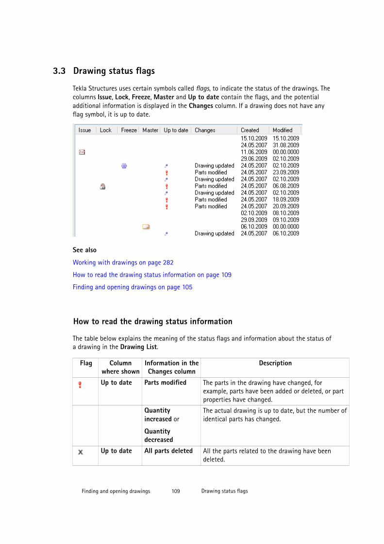
3.3 Drawing status flags
Tekla Structures uses certain symbols called flags, to indicate the status of the drawings. Thecolumns Issue, Lock, Freeze, Master and Up to date contain the flags, and the potentialadditional information is displayed in the Changes column. If a drawing does not have anyflag symbol, it is up to date.
See also
Working with drawings on page 282
How to read the drawing status information on page 109
Finding and opening drawings on page 105
How to read the drawing status information
The table below explains the meaning of the status flags and information about the status ofa drawing in the Drawing List.
Flag Columnwhere shown
Information in theChanges column
Description
Up to date Parts modified The parts in the drawing have changed, forexample, parts have been added or deleted, or partproperties have changed.
Quantityincreased or
Quantitydecreased
The actual drawing is up to date, but the number ofidentical parts has changed.
Up to date All parts deleted All the parts related to the drawing have beendeleted.
Finding and opening drawings 109 Drawing status flags
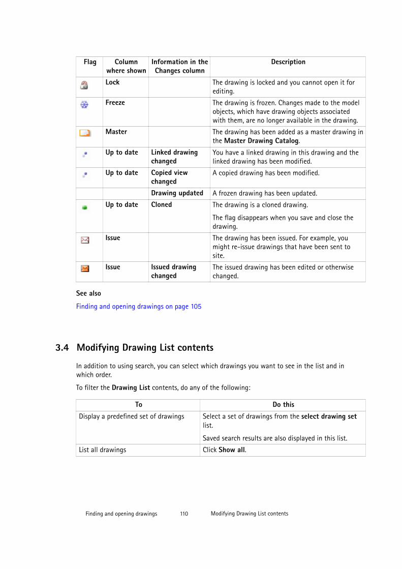
Flag Columnwhere shown
Information in theChanges column
Description
Lock The drawing is locked and you cannot open it forediting.
Freeze The drawing is frozen. Changes made to the modelobjects, which have drawing objects associatedwith them, are no longer available in the drawing.
Master The drawing has been added as a master drawing inthe Master Drawing Catalog.
Up to date Linked drawingchanged
You have a linked drawing in this drawing and thelinked drawing has been modified.
Up to date Copied viewchanged
A copied drawing has been modified.
Drawing updated A frozen drawing has been updated.
Up to date Cloned The drawing is a cloned drawing.
The flag disappears when you save and close thedrawing.
Issue The drawing has been issued. For example, youmight re-issue drawings that have been sent tosite.
Issue Issued drawingchanged
The issued drawing has been edited or otherwisechanged.
See also
Finding and opening drawings on page 105
3.4 Modifying Drawing List contents
In addition to using search, you can select which drawings you want to see in the list and inwhich order.
To filter the Drawing List contents, do any of the following:
To Do this
Display a predefined set of drawings Select a set of drawings from the select drawing setlist.
Saved search results are also displayed in this list.
List all drawings Click Show all.
Finding and opening drawings 110 Modifying Drawing List contents

To Do this
Invert the contents of the current list Click Invert.
This feature allows you to list the opposite of thecurrent content.
For example, if you had selected to display Lockeddrawings, clicking Invert shows all drawings exceptthe locked ones.
List selected drawings only Select the drawings and click Selected.
List up-to-date drawings only Click Up to date.
List drawings that need to be updated 1. Click Up to date.
2. Click Invert.
Lists only drawings associated with theobjects you have selected in the model.
1. Select objects in the model.
2. Click By parts.
This is an easy way to identify the drawings associatedwith a specific part, assembly or cast unit.
Sort the list according to Column name Click the column name.
See also
Working with drawings on page 282
Finding and opening drawings on page 105
3.5 Searching drawings and saving the search results
You can search for drawings in the Drawing List.
To search for drawings and save the results:
1. In the Drawing List, enter the search criteria in Enter search criteria.
2. If needed, you can limit the search so that it addresses only information in a certaincolumn by selecting a column from the Search in list.
3. If needed, you can also limit the search to the currently visible drawings by selectingSearch within the currently visible drawings.
4. Click Search.
5. Click Store to save the search results.
6. Enter a name for the search results in the Store Search Result dialog box and click OK.
Finding and opening drawings 111 Searching drawings and saving the search results
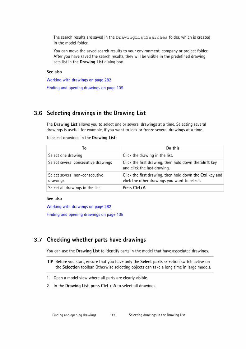
The search results are saved in the DrawingListSearches folder, which is createdin the model folder.
You can move the saved search results to your environment, company or project folder.After you have saved the search results, they will be visible in the predefined drawingsets list in the Drawing List dialog box.
See also
Working with drawings on page 282
Finding and opening drawings on page 105
3.6 Selecting drawings in the Drawing List
The Drawing List allows you to select one or several drawings at a time. Selecting severaldrawings is useful, for example, if you want to lock or freeze several drawings at a time.
To select drawings in the Drawing List:
To Do this
Select one drawing Click the drawing in the list.
Select several consecutive drawings Click the first drawing, then hold down the Shift keyand click the last drawing.
Select several non-consecutivedrawings
Click the first drawing, then hold down the Ctrl key andclick the other drawings you want to select.
Select all drawings in the list Press Ctrl+A.
See also
Working with drawings on page 282
Finding and opening drawings on page 105
3.7 Checking whether parts have drawings
You can use the Drawing List to identify parts in the model that have associated drawings.
TIP Before you start, ensure that you have only the Select parts selection switch active onthe Selection toolbar. Otherwise selecting objects can take a long time in large models.
1. Open a model view where all parts are clearly visible.
2. In the Drawing List, press Ctrl + A to select all drawings.
Finding and opening drawings 112 Selecting drawings in the Drawing List
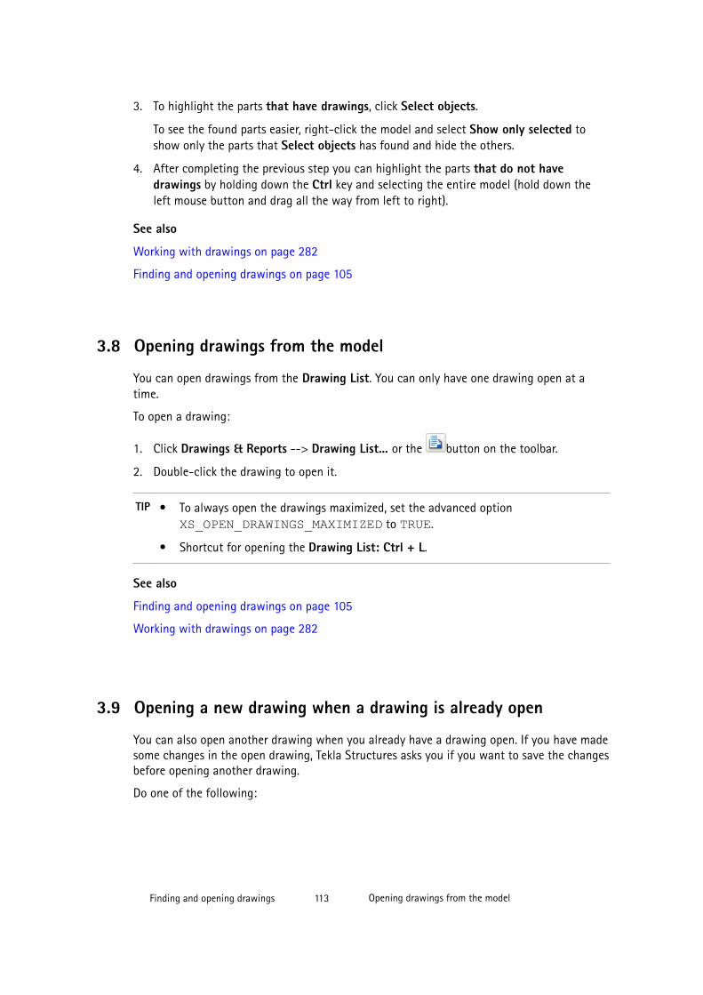
3. To highlight the parts that have drawings, click Select objects.
To see the found parts easier, right-click the model and select Show only selected toshow only the parts that Select objects has found and hide the others.
4. After completing the previous step you can highlight the parts that do not havedrawings by holding down the Ctrl key and selecting the entire model (hold down theleft mouse button and drag all the way from left to right).
See also
Working with drawings on page 282
Finding and opening drawings on page 105
3.8 Opening drawings from the model
You can open drawings from the Drawing List. You can only have one drawing open at atime.
To open a drawing:
1. Click Drawings & Reports --> Drawing List... or the button on the toolbar.
2. Double-click the drawing to open it.
TIP • To always open the drawings maximized, set the advanced option XS_OPEN_DRAWINGS_MAXIMIZED to TRUE.
• Shortcut for opening the Drawing List: Ctrl + L.
See also
Finding and opening drawings on page 105
Working with drawings on page 282
3.9 Opening a new drawing when a drawing is already open
You can also open another drawing when you already have a drawing open. If you have madesome changes in the open drawing, Tekla Structures asks you if you want to save the changesbefore opening another drawing.
Do one of the following:
Finding and opening drawings 113 Opening drawings from the model
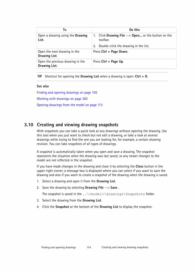
To Do this
Open a drawing using the DrawingList.
1. Click Drawing File --> Open... or the button on thetoolbar.
2. Double-click the drawing in the list.
Open the next drawing in theDrawing List.
Press Ctrl + Page Down.
Open the previous drawing in theDrawing List.
Press Ctrl + Page Up.
TIP Shortcut for opening the Drawing List when a drawing is open: Ctrl + O.
See also
Finding and opening drawings on page 105
Working with drawings on page 282
Opening drawings from the model on page 113
3.10 Creating and viewing drawing snapshotsWith snapshots you can take a quick look at any drawings without opening the drawing. Usethis tool when you just want to check but not edit a drawing, or take a look at severaldrawings while trying to find the one you are looking for, for example, a certain drawingrevision. You can take snapshots of all types of drawings.
A snapshot is automatically taken when you open and save a drawing. The snapshotrepresents the situation when the drawing was last saved, so any newer changes to themodel are not reflected in the snapshot.
If you have made changes in the drawing and close it by selecting the Close button in theupper-right corner, a message box is displayed where you can select if you want to save thedrawing and also if you want to create a snapshot of the drawing when the drawing is saved.
1. Select a drawing and open it from the Drawing List.
2. Save the drawing by selecting Drawing File --> Save .
The snapshot is saved in the ..\<model>\drawings\Snapshots folder.
3. Select the drawing from the Drawing List.
4. Click the Snapshot at the bottom of the Drawing List to display the snapshot.
Finding and opening drawings 114 Creating and viewing drawing snapshots
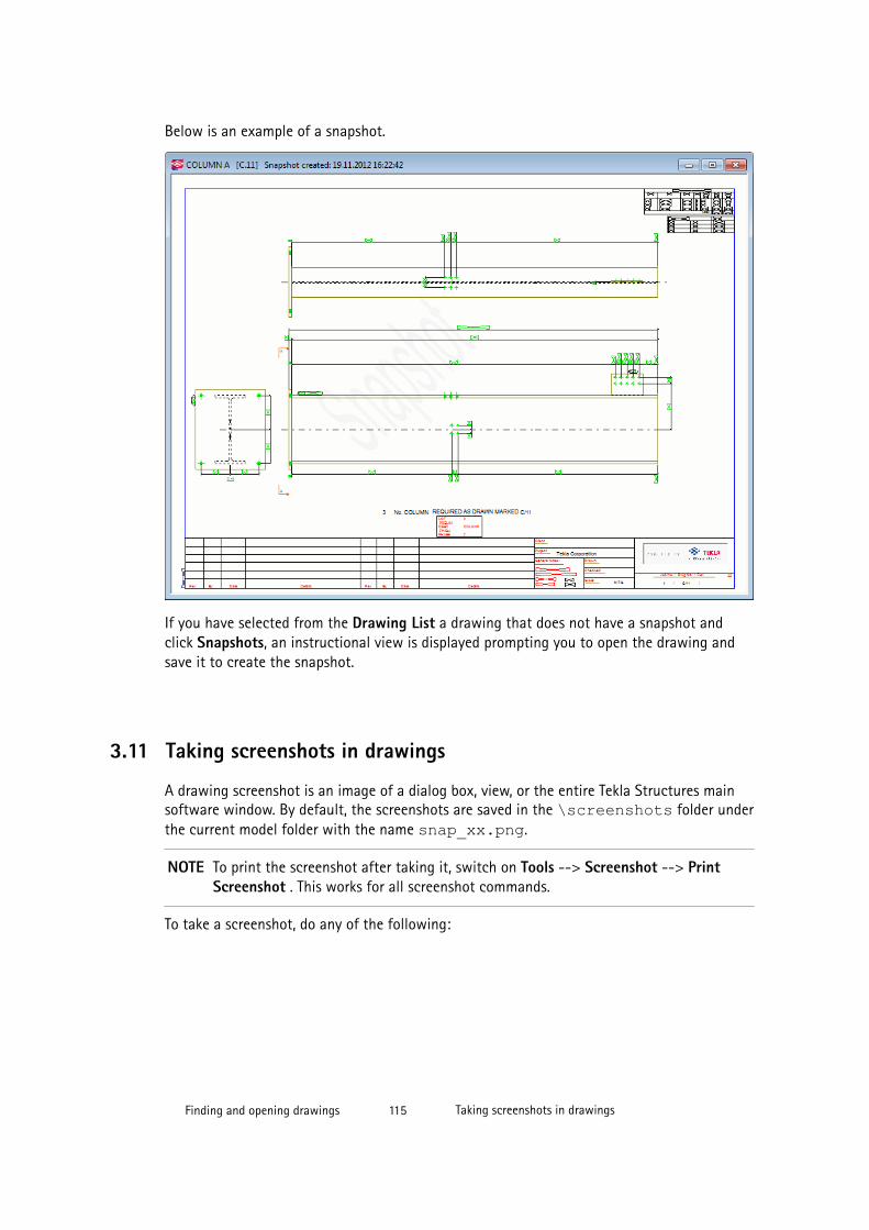
Below is an example of a snapshot.
If you have selected from the Drawing List a drawing that does not have a snapshot andclick Snapshots, an instructional view is displayed prompting you to open the drawing andsave it to create the snapshot.
3.11 Taking screenshots in drawings
A drawing screenshot is an image of a dialog box, view, or the entire Tekla Structures mainsoftware window. By default, the screenshots are saved in the \screenshots folder underthe current model folder with the name snap_xx.png.
NOTE To print the screenshot after taking it, switch on Tools --> Screenshot --> PrintScreenshot . This works for all screenshot commands.
To take a screenshot, do any of the following:
Finding and opening drawings 115 Taking screenshots in drawings
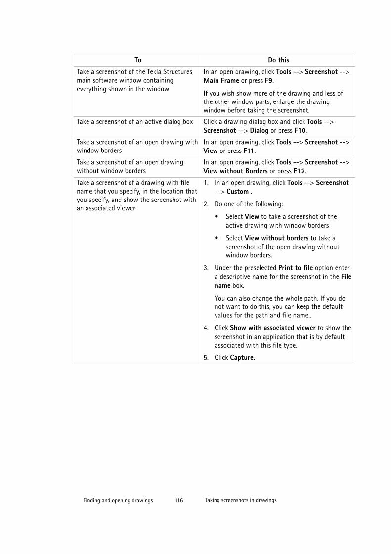
To Do this
Take a screenshot of the Tekla Structuresmain software window containingeverything shown in the window
In an open drawing, click Tools --> Screenshot -->Main Frame or press F9.
If you wish show more of the drawing and less ofthe other window parts, enlarge the drawingwindow before taking the screenshot.
Take a screenshot of an active dialog box Click a drawing dialog box and click Tools -->Screenshot --> Dialog or press F10.
Take a screenshot of an open drawing withwindow borders
In an open drawing, click Tools --> Screenshot -->View or press F11.
Take a screenshot of an open drawingwithout window borders
In an open drawing, click Tools --> Screenshot -->View without Borders or press F12.
Take a screenshot of a drawing with filename that you specify, in the location thatyou specify, and show the screenshot withan associated viewer
1. In an open drawing, click Tools --> Screenshot--> Custom .
2. Do one of the following:
• Select View to take a screenshot of theactive drawing with window borders
• Select View without borders to take ascreenshot of the open drawing withoutwindow borders.
3. Under the preselected Print to file option entera descriptive name for the screenshot in the Filename box.
You can also change the whole path. If you donot want to do this, you can keep the defaultvalues for the path and file name..
4. Click Show with associated viewer to show thescreenshot in an application that is by defaultassociated with this file type.
5. Click Capture.
Finding and opening drawings 116 Taking screenshots in drawings
4 Editing drawings
This section explains how to edit the drawings that you have created.
After you have created a drawing, you can modify properties of the layout and the views,building objects, and associative annotation objects already included in the drawing. You canalso add more views, associative and independent annotation objects, and shapes. You canalso change drawing colors.
Click the links below to find out more:
• Renaming drawings on page 118
• Giving titles to drawings on page 118
• Drawing views on page 119
• Dimensions on page 145
• Associative annotation objects on page 180
• Independent annotation objects on page 192
• Drawing shapes on page 201
• Building objects in drawings on page 203
• Custom presentations in drawings on page 208
• Exploding drawing plug-ins on page 210
• Welds in drawings on page 210
• Edge chamfers in drawings on page 228
• Pours in drawings on page 236
• Reference models in drawings on page 233
• Grids in drawings on page 241
• Symbols in drawings on page 243
• Changing drawing objects on page 252
• Colors in drawings on page 271
• User coordinate system (UCS) on page 275
• Saving drawings on page 278
Editing drawings 117 Taking screenshots in drawings
• Deleting unnecessary drawing files in single-user mode on page 278
• Closing drawings on page 279
• Keyboard shortcuts for drawings on page 280
4.1 Renaming drawings
Tekla Structures names the drawings according to the name given in the drawing properties.The drawing name is displayed in the Drawing List and in drawing templates.
To rename a drawing:
1. In the Drawing List, right-click the drawing and select Properties.
2. Switch all the check boxes off in the dialog box by clicking the on/off switch at the bottom of the dialog box.
3. Select the check box next to the Name box.
4. Enter the new name in the Name box.
5. Click Modify.
See also
Editing drawings on page 117
Modifying drawing settings on page 320
4.2 Giving titles to drawings
In addition to the drawing name, you can give titles for your drawings. Tekla Structuresshows the title in the Drawing List and in drawing and report templates. You can define upto three titles to use in drawing templates.
To give a title to a drawing:
1. In the Drawing List, right-click the drawing and select Properties.
2. Switch all the check boxes off in the dialog box by clicking the on/off switch at the bottom of the dialog box.
Select the check boxes next to the Title boxes you want to use.
3. Enter the titles.
4. Click Modify.
Editing drawings 118 Renaming drawings
TIP If you want to customize your print file names and use title values instead of drawing names inthem , you can define that the title entered in this dialog box is used in the print file name. Todo this, enter the value %TPL:TITLE1% (or %TPL:TITLE2% or %TPL:TITLE3%) for anadvanced option XS_DRAWING_PLOT_FILE_NAME_G (or _W, _A, _M or _C depending onthe drawing type) through Tools --> Options --> Advanced Options --> Printing .
See also
Editing drawings on page 117
Modifying drawing settings on page 320
Customizing print file names on page 305
4.3 Drawing viewsDrawing views contain the selected parts of Tekla Structures objects, and marks, dimensionsand other objects that have selected to add. The drawing view is another way of looking atthe model. Drawings may include several views.
You can have different types of views in Tekla Structures drawings:
• Main views: front, top, back and bottom views
• Section views
• End views
• Single-part views
• 3D views
• Detail views
• Key plan views
• Views along grid lines
• Elevation views
• Plan views
In addition to the views Tekla Structures creates automatically in a drawing based on thedrawing properties, you can also add new ones in the open drawing.
See also
Editing drawings on page 117
Adding views in drawings manually on page 120
Copying drawing views from another drawing on page 133
Linking views from another drawing on page 136
Moving views to another drawing on page 133
Editing drawings 119 Drawing views
Modifying drawing views on page 136
Automatic drawing views on page 364
View properties in drawings on page 551
Section view properties on page 555
Key plans on page 349
Adding views in drawings manually
Once you have created drawings, you can add more views to them manually. You can createdrawing views of:
• Entire model
• Selected areas in a model
• Views in the same drawing
• Single parts in an assembly
• Objects in 3D
• Sections in a drawing
• Details in a drawing
• Reinforcement meshes
See also
Creating a section view on page 120
Creating a detail view on page 124
Creating a curved section view on page 123
Creating additional views of parts on page 126
Creating a drawing view of an entire model view on page 127
Creating a drawing view of a selected area in a model view on page 128
Creating a drawing view of a selected area in a drawing view on page 129
Adding single-part views in assembly drawings on page 132
Creating a drawing view for a reinforcement mesh (RebarMeshViewCreator) on page 129
Creating a section view
You can create section views of the parts in a drawing view in an open drawing that containsat least one view.
To modify the properties and create the section view:
Editing drawings 120 Drawing views
1. Click Annotating --> Properties --> Section Mark .
2. Modify the cutting line, section mark, and section view label properties in the Sectionsymbol properties dialog box.
3. Click OK or Apply.
4. Hold down Shift and click View --> Create Drawing View --> Section View .
5. Modify the view properties as required.
6. Click OK or Apply.
7. Pick two points to define the position of the section plane.
It is easier to pick the points if you activate orthogonal snapping by clicking Tools -->Ortho or pressing O.
For beams, you can also try picking the top line of the beam and then the bottom line ofthe beam using the snap switch Snap to perpendicular points.
8. Pick two points to define the direction of the cut box and the section view depth.
When you pick the cut box, exaggerate a little. You ca adjust the view depth and theview boundary also later on.
The direction of the section is the direction where the section mark arrows are pointing.
9. Pick the position for the section view.
A view symbol follows the mouse pointer allowing you to see where you are about toplace the section view.
The depth to the opposite direction is zero (0).
Tekla Structures creates the section view using the current properties in the ViewProperties and Section Symbol Properties dialog boxes and adds a section mark in theoriginal view. You can change the properties after creating the view.
TIP • The view boundary of the created section view remains selected, and youcan adjust the depth and the height of the view boundary by dragging it.
• If necessary, change the view scale of the section view: Double-click theview frame, clear all other selections using the toggle switch at thebottom, select only the Scale option, and adjust the scale.
• If you want to create another view, start the Section View commandagain.
Editing drawings 121 Drawing views

1. The first two picked points indicate the position of the section plane.
2. The third picked point indicates the direction of the cut box and the depth of the sectionview. Here you can exaggerate a little.
Editing drawings 122 Drawing views
3. The fourth pick finalizes the cut box.
4. A view symbol follows the mouse pointer while you are placing the section view. Thesection view is placed in the selected location. The section view remains selected and theview boundary highlighted right after the view creation.
The section mark is drawn in the original view. The view boundary of the section view isalso highlighted in the original view right after the view creation.
See also
Adding views in drawings manually on page 120
Modifying section properties on page 142
Defining view labels and view label marks on page 367
Section view properties on page 555
View properties in drawings on page 551
Modifying drawing view properties on page 142
Creating a curved section view
You can create a curved section view of an existing drawing view. This tool is useful whenyou want to visualize an unfolded face of a building or to manage cladding.
1. Open a drawing.
2. Click Annotating --> Properties --> Section Mark .
3. Modify the cutting line, section mark, and section view label properties.
4. Click OK or Apply.
5. Hold down Shift and click View --> Create Drawing View --> Curved Section View .
6. Modify the view properties as required.
7. Click OK or Apply.
8. Pick three points on the cut plane.
9. Pick two points to indicate the cut box.
10. Pick a point to indicate the location of the curved section view.
A symbol follows the cursor allowing you to see where you are about to place the curvedsection view.
Tekla Structures creates the curved section view using the current properties in the ViewProperties and Section Symbol Properties dialog boxes and adds a section mark in theoriginal view. You can change the properties after creating the view.
See also
Adding views in drawings manually on page 120
Editing drawings 123 Drawing views

Modifying section properties on page 142
Defining view labels and view label marks on page 367
Section view properties on page 555
Modifying drawing view properties on page 142
View properties in drawings on page 551
Section view properties on page 555
Creating a detail view
You can create a detail view from a selected area in an existing drawing view in anotherview. The scale of the detail view is by default the same as that of the main view, but in someenvironments the detail view is scaled up. The direction of the detail view is the same as thatof the original view.
1. Open a drawing.
2. Click Annotating --> Properties --> Detail Mark .
3. Enter a name for the detail, and modify the detail view lable, detail boundary and detailmark properties in the Detail Symbol Properties dialog box.
The shape of the detail boundary you select affects the way you select the area for yourdetail.
4. Click OK or Apply.
5. Hold down Shift and click View --> Create Drawing View --> Detail View .
6. Modify the view properties as required.
7. Click OK or Apply.
8. Depending on the selected detail boundary shape, do one of the following:
• If the shape is Circle, pick the center point of the circle and then pick a point on thecircle.
• If the shape is Rectangle, pick corner points for the rectangle.
9. Pick a position for the detail mark.
10. Pick a position for the detail view.
Tekla Structures creates the detail view using the current properties in the View Propertiesdialog box and Detail Symbol Properties dialog box. However, the detail view takes the view
Editing drawings 124 Drawing views
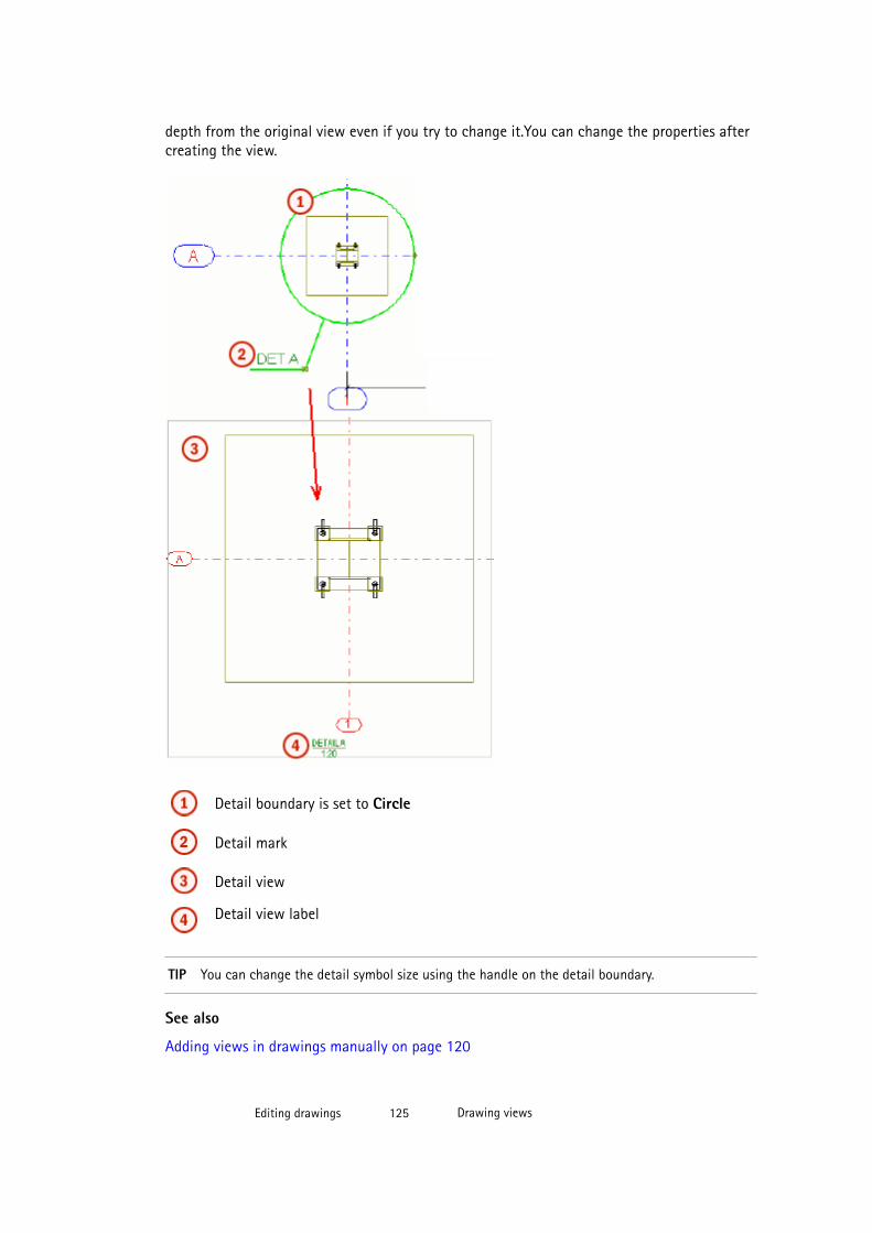
depth from the original view even if you try to change it.You can change the properties aftercreating the view.
Detail boundary is set to Circle
Detail mark
Detail view
Detail view label
TIP You can change the detail symbol size using the handle on the detail boundary.
See also
Adding views in drawings manually on page 120
Editing drawings 125 Drawing views
Modifying detail properties on page 144
Modifying drawing view properties on page 142
View properties in drawings on page 551
Defining start number or letter for detail view label and mark on page 126
Defining start number or letter for detail view label and mark
Before creating the detail view label and detail mark define a start number or letter in thedrawing properties.
To define the start number or letter:
1. Double-click an open drawing.
2. Click the check box toggle selection button at the bottom of the dialog box, and selectonly the check box next to the Detail view button.
3. Click Detail View.
4. Enter the start number or letter.
5. Click Modify.
See also
Creating a detail view on page 124
Creating additional views of parts
You can create additional views of a part within a single-part, cast unit or assembly drawing.You can select the part plane (front, top, back, bottom) to use or create a 3 D view.
1. Open a drawing.
2. Click View --> Create Drawing View --> Of Parts in Drawing and select one of thecommands Front, Top, Back, Bottom, 3D.
Tekla Structures creates the view using the current properties in the View Propertiesdialog box.
Tekla Structures will not create views on planes that already have a view in the drawing.
3. Double-click the view frame to open the View Properties dialog box and modify theproperties as required.
TIP For 3D views, you may want to modify the view angle.
4. Click Modify.
Editing drawings 126 Drawing views

Example
In the example below, the drawing originally contained only the front view. A 3D view and atop view were added. The angle of the 3D view was modified in the View Properties dialogbox.
See also
Adding views in drawings manually on page 120
Modifying drawing view properties on page 142
View properties in drawings on page 551
Creating a drawing view of an entire model view
You can create a drawing view of an entire model view and add it in the drawing.
To create a view of the entire model view:
1. Open a drawing.
2. Open a model view list by clicking Views --> Model Views --> Model View List... .
3. Hold down Shift and click View --> Create Drawing View --> Of Entire Model View .
4. Modify the view properties, for example the view scale, and click OK or Apply
5. Open a model view from the model view list.
6. Click the open model view.
Editing drawings 127 Drawing views
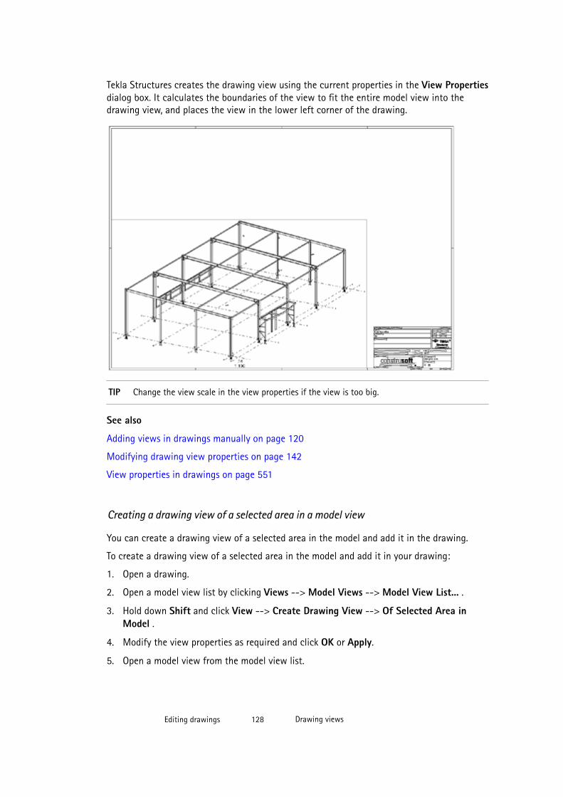
Tekla Structures creates the drawing view using the current properties in the View Propertiesdialog box. It calculates the boundaries of the view to fit the entire model view into thedrawing view, and places the view in the lower left corner of the drawing.
TIP Change the view scale in the view properties if the view is too big.
See also
Adding views in drawings manually on page 120
Modifying drawing view properties on page 142
View properties in drawings on page 551
Creating a drawing view of a selected area in a model view
You can create a drawing view of a selected area in the model and add it in the drawing.
To create a drawing view of a selected area in the model and add it in your drawing:
1. Open a drawing.
2. Open a model view list by clicking Views --> Model Views --> Model View List... .
3. Hold down Shift and click View --> Create Drawing View --> Of Selected Area inModel .
4. Modify the view properties as required and click OK or Apply.
5. Open a model view from the model view list.
Editing drawings 128 Drawing views
6. Pick two corners in the model to define the x and y dimensions of the drawing view. Thex and y directions use the coordinate system of the model view. The view depth of thedrawing view is the same as the depth of the model view.
Tekla Structures creates the drawing view using the current properties in the View Propertiesdialog box. Tekla Structures places the view in the lower left corner of the drawing.
See also
Adding views in drawings manually on page 120
Modifying drawing view properties on page 142
View properties in drawings on page 551
Creating a drawing view of a selected area in a drawing view
You can create a new drawing view of an area in an existing drawing view.
To create a new drawing view of an area in the existing drawing view:
1. Open a drawing.
2. Hold down Shift and click View --> Create Drawing View --> Of Selected Area inDrawing View .
3. Modify the view label color.
Other view properties are inherited from the original drawing view.
4. Click OK or Apply.
5. Select the area in the drawing view of which you want to make a new view.
6. Select a position for the new view.
A symbol representing the view that you are about to place follows the mouse pointer, soit is easier for you to see where to place the view.
Tekla Structures creates the drawing view using the view properties of the original view.
See also
Adding views in drawings manually on page 120
Modifying drawing view properties on page 142
View properties in drawings on page 551
Creating a drawing view for a reinforcement mesh (RebarMeshViewCreator)You can create drawing views each containing one reinforcement mesh by using the RebarMeshViewCreator macro. You can create mesh views in general arrangementand cast unit drawings.
Editing drawings 129 Drawing views
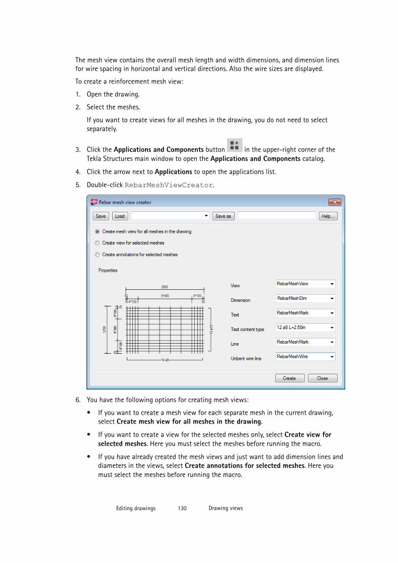
The mesh view contains the overall mesh length and width dimensions, and dimension linesfor wire spacing in horizontal and vertical directions. Also the wire sizes are displayed.
To create a reinforcement mesh view:
1. Open the drawing.
2. Select the meshes.
If you want to create views for all meshes in the drawing, you do not need to selectseparately.
3. Click the Applications and Components button in the upper-right corner of theTekla Structures main window to open the Applications and Components catalog.
4. Click the arrow next to Applications to open the applications list.
5. Double-click RebarMeshViewCreator.
6. You have the following options for creating mesh views:
• If you want to create a mesh view for each separate mesh in the current drawing,select Create mesh view for all meshes in the drawing.
• If you want to create a view for the selected meshes only, select Create view forselected meshes. Here you must select the meshes before running the macro.
• If you have already created the mesh views and just want to add dimension lines anddiameters in the views, select Create annotations for selected meshes. Here youmust select the meshes before running the macro.
Editing drawings 130 Drawing views
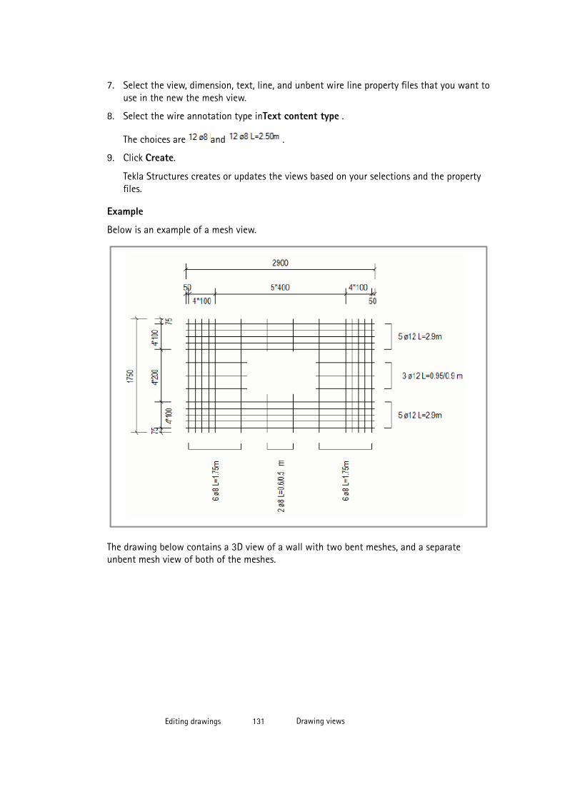
7. Select the view, dimension, text, line, and unbent wire line property files that you want touse in the new the mesh view.
8. Select the wire annotation type inText content type .
The choices are and .
9. Click Create.
Tekla Structures creates or updates the views based on your selections and the propertyfiles.
Example
Below is an example of a mesh view.
The drawing below contains a 3D view of a wall with two bent meshes, and a separateunbent mesh view of both of the meshes.
Editing drawings 131 Drawing views
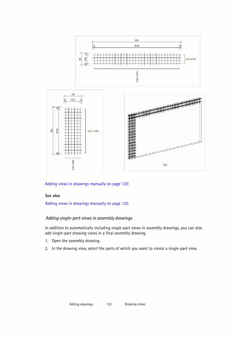
Adding views in drawings manually on page 120
See also
Adding views in drawings manually on page 120
Adding single-part views in assembly drawings
In addition to automatically including single-part views in assembly drawings, you can alsoadd single-part drawing views in a final assembly drawing.
1. Open the assembly drawing.
2. In the drawing view, select the parts of which you want to create a single-part view.
Editing drawings 132 Drawing views
3. Right-click and select Create single-part views.
Tekla Structures adds the single-part views to the assembly drawing using the currentproperties in the Assembly Drawing Properties dialog box ( Assembly Drawing Properties --> Layout --> Other --> Single-part attributes ).
See also
XS_NO_END_VIEWS_TO_INCLUDED_SINGLE_DRAWINGS
Including single-part drawings in assembly drawings on page 370
Copying drawing views from another drawing
You can copy drawing views from other drawings.
To copy a drawing view from another drawing:
1. Open a drawing.
2. Open the Drawing List by pressing Ctrl + O.
3. Select the drawing containing the view you want to copy. You can select severaldrawings.
4. Click View --> Add Views from Other Drawing and select Copy or Copy with Layout:
• Copy copies the views from the selected drawings as such to the open drawing. TeklaStructures does not copy the drawing layout.
• Copy with Layout copies the views and layout from the selected drawings as such tothe open drawing.
NOTE Copied drawing views do not update when the original views change.
See also
Adding views in drawings manually on page 120
View properties in drawings on page 551
Editing drawings 133 Drawing views
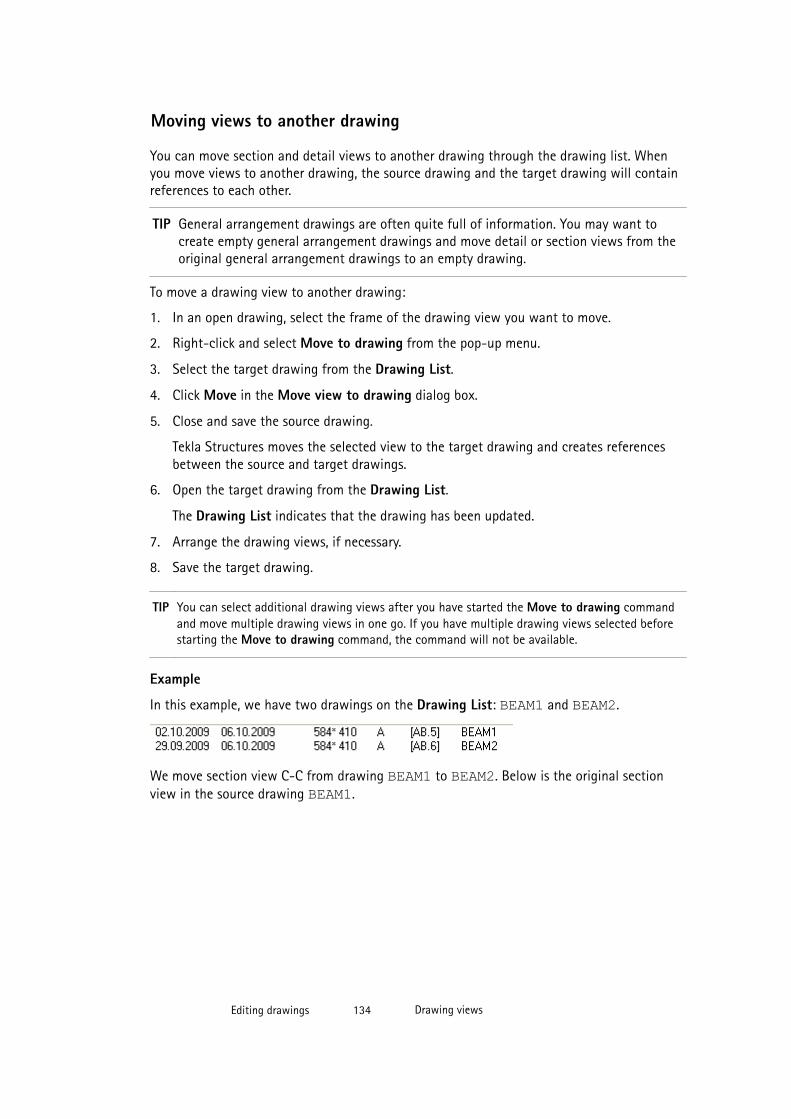
Moving views to another drawing
You can move section and detail views to another drawing through the drawing list. Whenyou move views to another drawing, the source drawing and the target drawing will containreferences to each other.
TIP General arrangement drawings are often quite full of information. You may want tocreate empty general arrangement drawings and move detail or section views from theoriginal general arrangement drawings to an empty drawing.
To move a drawing view to another drawing:
1. In an open drawing, select the frame of the drawing view you want to move.
2. Right-click and select Move to drawing from the pop-up menu.
3. Select the target drawing from the Drawing List.
4. Click Move in the Move view to drawing dialog box.
5. Close and save the source drawing.
Tekla Structures moves the selected view to the target drawing and creates referencesbetween the source and target drawings.
6. Open the target drawing from the Drawing List.
The Drawing List indicates that the drawing has been updated.
7. Arrange the drawing views, if necessary.
8. Save the target drawing.
TIP You can select additional drawing views after you have started the Move to drawing commandand move multiple drawing views in one go. If you have multiple drawing views selected beforestarting the Move to drawing command, the command will not be available.
Example
In this example, we have two drawings on the Drawing List: BEAM1 and BEAM2.
We move section view C-C from drawing BEAM1 to BEAM2. Below is the original sectionview in the source drawing BEAM1.
Editing drawings 134 Drawing views
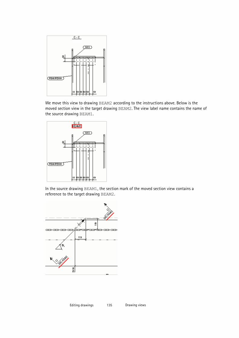
We move this view to drawing BEAM2 according to the instructions above. Below is themoved section view in the target drawing BEAM2. The view label name contains the name ofthe source drawing BEAM1.
In the source drawing BEAM1, the section mark of the moved section view contains areference to the target drawing BEAM2.
Editing drawings 135 Drawing views

See also
Defining automatic free or fixed placement of drawing views on page 363
Arranging drawing views on page 141
Adding views in drawings manually on page 120
Modifying drawing views on page 136
XS_SECTION_VIEW_REFERENCE
XS_SECTION_SYMBOL_REFERENCE
XS_DETAIL_VIEW_REFERENCE
XS_DETAIL_SYMBOL_REFERENCE
Linking views from another drawing
You can link drawing views from other drawings.
Linked drawing views update when the original views change.
To link drawing views:
1. Open a drawing.
2. Open the Drawing List by pressing Ctrl + O.
3. Select the drawing containing the view you want to link. You can select several drawings.
4. Click View --> Add Views from Other Drawing and select Link or Link with Layout:
• Link displays the views of the selected drawings in the open drawing. TeklaStructures does not copy the drawing layout.
• Link with Layout displays the views and the layout of the selected drawings in theopen drawing.
See also
Adding views in drawings manually on page 120
Modifying drawing views
Once you have added the necessary views in your drawing, you may want to modify the viewcontents, appearance, size, location and rotation.
See also
Drawing views on page 119
Resizing the drawing view boundary on page 137
Moving drawing views on page 139
Editing drawings 136 Drawing views

Aligning drawing views on page 140
Rotating drawing views on page 141
Arranging drawing views on page 141
Modifying drawing view properties on page 142
Modifying detail properties on page 144
Modifying section properties on page 142
Resizing the drawing view boundary
The view boundary or view restriction box is the dashed frame around the contents of adrawing view, which becomes visible when you click the view frame. You can resize the viewboundary, for example, to show just a specific part of the view contents.
When you select a view, the view boundary is highlighted also in other views. When youchange the selected view's boundary in the other views using view boundary handles, thechange can be seen in the view boundary of the selected view. This way you can easily adjustthe section view plane and view depth, and you do not need to go to the view propertiesdialog box to do this.
To resize the view boundary:
1. Click the view frame.
2. Click one of the handles on the view boundary.
3. Drag the handles along the x or y axis of the view.
When the view boundary changes size, the view frame adjusts with the new boundarysize.
Editing drawings 137 Drawing views
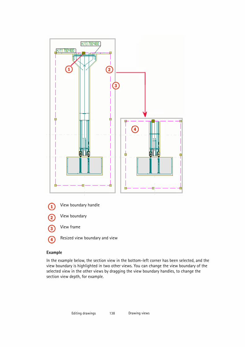
View boundary handle
View boundary
View frame
Resized view boundary and view
Example
In the example below, the section view in the bottom-left corner has been selected, and theview boundary is highlighted in two other views. You can change the view boundary of theselected view in the other views by dragging the view boundary handles, to change thesection view depth, for example.
Editing drawings 138 Drawing views
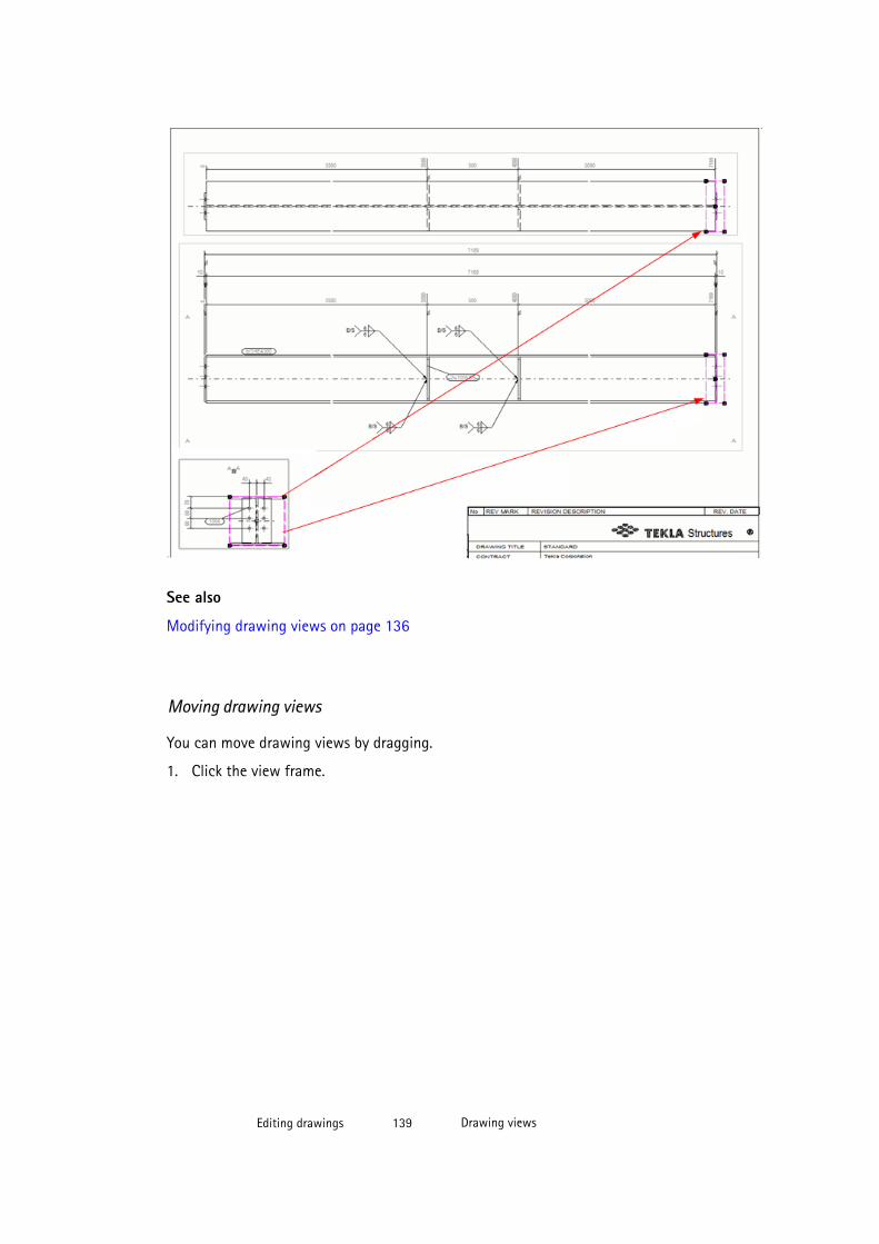
See also
Modifying drawing views on page 136
Moving drawing views
You can move drawing views by dragging.
1. Click the view frame.
Editing drawings 139 Drawing views
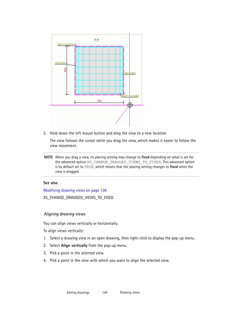
2. Hold down the left mouse button and drag the view to a new location.
The view follows the cursor while you drag the view, which makes it easier to follow theview movement.
NOTE When you drag a view, its placing setting may change to fixed depending on what is set forthe advanced option XS_CHANGE_DRAGGED_VIEWS_TO_FIXED. This advanced optionis by default set to TRUE, which means that the placing setting changes to fixed when theview is dragged.
See also
Modifying drawing views on page 136
XS_CHANGE_DRAGGED_VIEWS_TO_FIXED
Aligning drawing views
You can align views vertically or horizontally.
To align views vertically:
1. Select a drawing view in an open drawing, then right-click to display the pop-up menu.
2. Select Align vertically from the pop-up menu.
3. Pick a point in the selected view.
4. Pick a point in the view with which you want to align the selected view.
Editing drawings 140 Drawing views

Tekla Structures moves the views so that the picked points line up vertically.
See also
Modifying drawing views on page 136
Rotating drawing views
You can rotate the views in drawings.
1. Click the frame of the view you want to rotate.
2. Click View --> Rotate Drawing View... .
3. Enter the angle in degrees, for example, 90 or -90, in the displayed dialog box and clickRotate.
See also
Modifying drawing views on page 136
Arranging drawing views
You can fit the drawing views so that they include all the connected objects, and rearrangethe drawing views using the current properties in the Layout Properties properties dialogbox.
To fit and arrange drawing views:
• Click View --> Arrange Drawing Views .
Editing drawings 141 Drawing views

NOTE • Arrange Drawing Views only affects views where the Place is set to Free in theview properties. Fixed views are not moved.
• If you have set XS_CHANGE_DRAGGED_VIEWS_TO_FIXED to TRUE(default) and drag a view in a drawing, the view becomes fixed, and the ArrangeDrawing Views command does not work
• Arrange Drawing Views may change the drawing size if you have usedautomatic scaling of drawing views.
See also
Modifying drawing views on page 136
Modifying drawing view properties
You can modify view properties in the final drawing view by view or in selected views.
To modify view properties:
1. Do one of the following:
• If you want to modify the properties in several views, hold down Ctrl and click theview frames of the views you want to modify and click View --> Drawing ViewProperties .
• To modify the properties of one view, double-click the view frame.
2. Clear all the check boxes in the dialog box by clicking the on/off switch at thebottom of the dialog box.
3. Select the check boxes next to the properties you want to modify.
4. Modify the view properties as required.
For example, change the view Scale.
5. Click Modify in each of the subdialog boxes where you change the properties.
6. If there are some object level settings that you want to apply, click the Edit settingsbutton and load the object settings that you want to use. Click Modify.
See also
View properties in drawings on page 551
Modifying drawing views on page 136
Modifying view-level drawing properties on page 327
Editing drawings 142 Drawing views
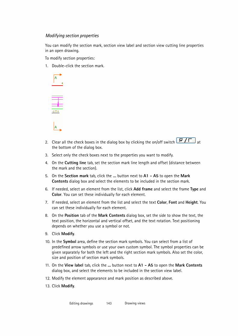
Modifying section properties
You can modify the section mark, section view label and section view cutting line propertiesin an open drawing.
To modify section properties:
1. Double-click the section mark.
2. Clear all the check boxes in the dialog box by clicking the on/off switch atthe bottom of the dialog box.
3. Select only the check boxes next to the properties you want to modify.
4. On the Cutting line tab, set the section mark line length and offset (distance betweenthe mark and the section).
5. On the Section mark tab, click the ... button next to A1 - A5 to open the MarkContents dialog box and select the elements to be included in the section mark.
6. If needed, select an element from the list, click Add frame and select the frame Type andColor. You can set these individually for each element.
7. If needed, select an element from the list and select the text Color, Font and Height. Youcan set these individually for each element.
8. On the Position tab of the Mark Contents dialog box, set the side to show the text, thetext position, the horizontal and vertical offset, and the text rotation. Text positioningdepends on whether you use a symbol or not.
9. Click Modify.
10. In the Symbol area, define the section mark symbols. You can select from a list ofpredefined arrow symbols or use your own custom symbol. The symbol properties can begiven separately for both the left and the right section mark symbols. Also set the color,size and position of section mark symbols.
11. On the View label tab, click the ... button next to A1 - A5 to open the Mark Contentsdialog box, and select the elements to be included in the section view label.
12. Modify the element appearance and mark position as described above.
13. Click Modify.
Editing drawings 143 Drawing views
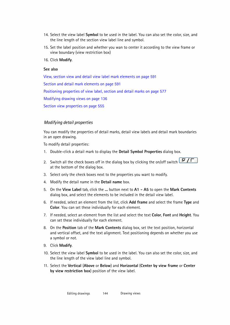
14. Select the view label Symbol to be used in the label. You can also set the color, size, andthe line length of the section view label line and symbol.
15. Set the label position and whether you wan to center it according to the view frame orview boundary (view restriction box)
16. Click Modify.
See also
View, section view and detail view label mark elements on page 591
Section and detail mark elements on page 591
Positioning properties of view label, section and detail marks on page 577
Modifying drawing views on page 136
Section view properties on page 555
Modifying detail properties
You can modify the properties of detail marks, detail view labels and detail mark boundariesin an open drawing.
To modify detail properties:
1. Double-click a detail mark to display the Detail Symbol Properties dialog box.
2. Switch all the check boxes off in the dialog box by clicking the on/off switch at the bottom of the dialog box.
3. Select only the check boxes next to the properties you want to modify.
4. Modify the detail name in the Detail name box.
5. On the View Label tab, click the ... button next to A1 - A5 to open the Mark Contentsdialog box, and select the elements to be included in the detail view label.
6. If needed, select an element from the list, click Add frame and select the frame Type andColor. You can set these individually for each element.
7. If needed, select an element from the list and select the text Color, Font and Height. Youcan set these individually for each element.
8. On the Position tab of the Mark Contents dialog box, set the text position, horizontaland vertical offset, and the text alignment. Text positioning depends on whether you usea symbol or not.
9. Click Modify.
10. Select the view label Symbol to be used in the label. You can also set the color, size, andthe line length of the view label line and symbol.
11. Select the Vertical (Above or Below) and Horizontal (Center by view frame or Centerby view restriction box) position of the view label.
Editing drawings 144 Drawing views
12. Go to the Detail boundary tab and define the shape of the boundary and the color andtype of the bounding line.
Use the advanced option XS_DETAIL_BOUNDARY_RADIUS for setting a fixed sizefor the detail boundary.
13. On to the Detail mark tab, click the ... button next to A1 - A5 to open the MarkContents dialog box and select the elements to be included in the detail mark.
14. Modify the element appearance and mark position as described above.
15. Click Modify.
16. Select the detail mark Symbol to be used in the mark. You can also change the color andsize of the symbol.
17. Click modify in the Detail Symbol Properties dialog box.
See also
View, section view and detail view label mark elements on page 591
Section and detail mark elements on page 591
4.4 DimensionsIn addition to the automatically created dimensions defined in the drawing properties of thecreated drawings, Tekla Structures contains several tools for modifying the automaticallycreated dimensions and for adding new dimensions in the final drawing.
See also
Example: Manual dimensions on page 147
Adding manual dimensions using User Coordinate System on page 152
Adding tags to dimensions on page 154
Example: Filtering out dimension tag content on page 156
Adding dual dimensions manually on page 158
Recreating dimensions for all parts on page 159
Adding manual dimensions on page 146
Adding manual dimensions to general arrangement drawings on page 152
Adding predefined reinforcement dimensions on page 160
Adding dimension (distribution) lines to reinforcing bars on page 161
Dimensioning reinforcing bar groups on page 163
Modifying dimension properties on page 171
Automatic dimension settings on page 396
Editing drawings 145 Dimensions

Creating exaggerated dimensions on page 456
Dimensioning center of gravity on page 167
Dimension mark and dimension tag properties on page 560
Dimension and dimensioning properties on page 556
Adding manual dimensions
To add dimensions:
1. Hold down Shift, click Dimensioning and select one of the dimensioning commandsdepending on the type of dimension you want to create:
• Add Horizontal Dimension: Create a dimension in the x direction by picking thepoints to be dimensioned. X depends on the current UCS.
• Add Vertical Dimension: Create a dimension in the y direction by picking the pointsto be dimensioned. Y depends on the current UCS.
• Add Orthogonal Dimension: Create a dimension in either the x or y direction bypicking the points to be dimensioned. Tekla Structures uses the direction of the largeroverall distance. X and y depend on the current UCS.
• Add Parallel Dimension: Create a dimension parallel to a line you define. First picktwo points to define the direction of the dimension line and then pick the points tobe dimensioned.
• Add Perpendicular Dimension: Create a dimension perpendicular to a line youdefine. First pick two points to set the direction of the dimension line, then pick thepoints to be dimensioned.
• Add Free Dimension: Create a dimension parallel to a line between any two pointsyou pick.
• Add Curved Dimension With Orthogonal Reference Lines: Create curved dimensionwith orthogonal reference lines: Pick three points to define the arc and pick thepoints to be dimensioned. The dimension text on the line can be either a distance oran angle value.
• Add Curved Dimension With Radial Reference Lines: Create curved dimension withradial reference lines. Pick three points to define the arc and pick the points to bedimensioned. The dimension text on the line can be either a distance or an anglevalue.
• Add Radial Dimension: Create radial dimension. Pick three points to define the arcand pick a position for the dimension.
• Add Angular Dimension: Create angular dimension. Pick the vertex point and twopoints to define the angle. Pick the side to place the dimension.
2. Modify the dimension properties in the properties dialog box.
3. Add the desired elements in dimension marks and modify their properties.
Editing drawings 146 Dimensions
4. Add dimension tags with the desired elements as required and set the dimension tagrotation.
Here you can also select to include part count to dimension tags and select a filter thatremoves the desired default content from the tag.
The available dimension mark and dimension tag mark elements are the same as thosefor the part, bolt, reinforcement and surface treatment marks.
5. Click OK or Apply.
6. Add the dimensions by following the instructions on the status bar.
7. Drag the dimensions to the desired locations.
When you drag the dimensions, the Placing setting changes to fixed by default.
NOTE • It is very important to use correct snap switches to get the dimensions correct.You can change the switch temporarily by right-clicking and selecting the switchthat suits the best for your purpose.
• In dimension types where you click the middle mouse button to place thedimension line, the placement setting affects the result. If you have set Placingto fixed, the position you click will be the location of the dimension line. If youhave set Placing to free, the middle mouse button click defines which side ofthe object the dimension line is located on, and Tekla Structures places thedimension line.
• You can also pick outside the view when you place the dimensions. The viewframe is resized automatically.
See also
Object protection and placement settings in drawings on page 357
XS_CHANGE_DRAGGED_DIMENSIONS_TO_FIXED
Modifying dimension properties on page 171
Dimension and dimensioning properties on page 556
Changing the prefix in radial dimensions on page 458
Adding tags to dimensions on page 154
Mark elements on page 583
Editing drawings 147 Dimensions
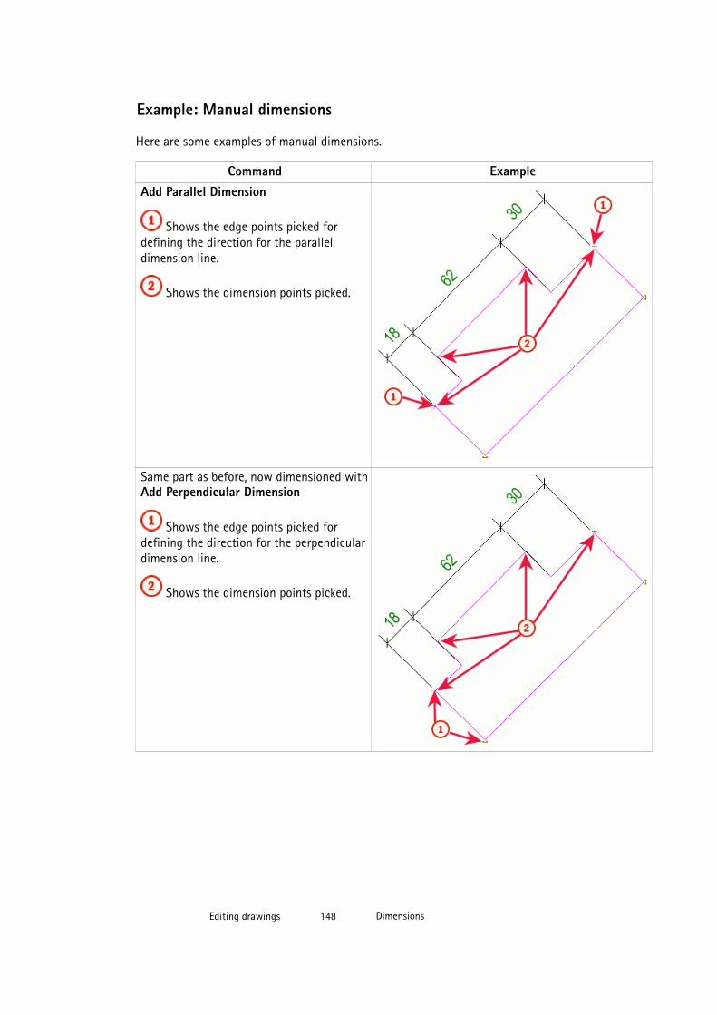
Example: Manual dimensions
Here are some examples of manual dimensions.
Command ExampleAdd Parallel Dimension
Shows the edge points picked fordefining the direction for the paralleldimension line.
Shows the dimension points picked.
Same part as before, now dimensioned withAdd Perpendicular Dimension
Shows the edge points picked fordefining the direction for the perpendiculardimension line.
Shows the dimension points picked.
Editing drawings 148 Dimensions
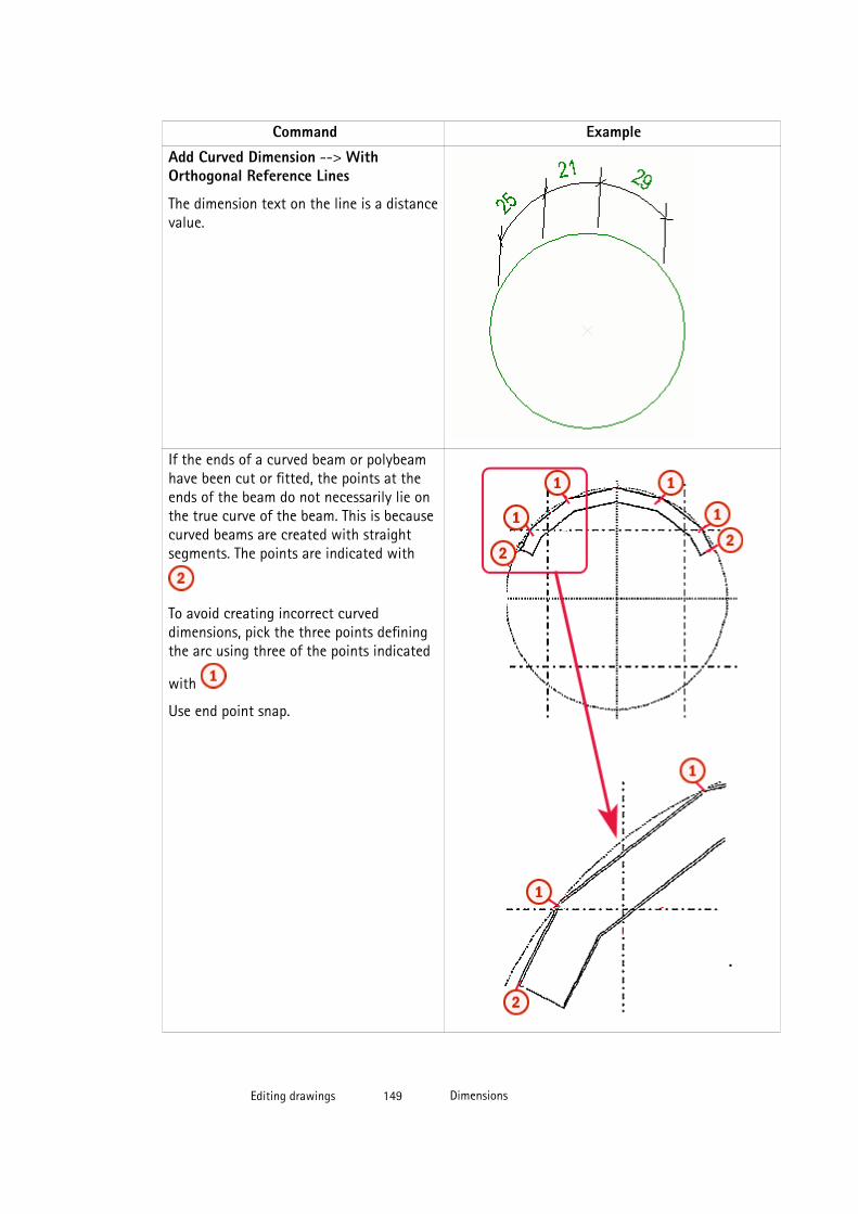
Command Example
Add Curved Dimension --> WithOrthogonal Reference Lines
The dimension text on the line is a distancevalue.
If the ends of a curved beam or polybeamhave been cut or fitted, the points at theends of the beam do not necessarily lie onthe true curve of the beam. This is becausecurved beams are created with straightsegments. The points are indicated with
To avoid creating incorrect curveddimensions, pick the three points definingthe arc using three of the points indicated
with
Use end point snap.
Editing drawings 149 Dimensions

Command Example
Add Curved Dimension --> With RadialReference Lines
Curved set to Distance.
The dimension text on the line is a distancevalue.
Add Curved Dimension --> With RadialReference Lines
Curved set to Angle.
The dimension text on the line is an anglevalue.
Editing drawings 150 Dimensions

Command ExampleAdd Angular Dimension
Angle set to Degrees at angle vertex
Add Angular Dimension
Angle set to Degrees on side
Add Angular Dimension
Angle set to Triangle.
Triangle base length set to 100
Add Radial Dimension
Editing drawings 151 Dimensions
See also
Dimensions on page 145
Adding manual dimensions on page 146
Adding manual dimensions to general arrangement drawings
You can dimension parts to grids along their X, Y, or X and Y axis and along grid lines ingeneral arrangement drawing plan views.
Limitations: Parts like beams that are not located along the grids are not dimensioned.
To add part dimensions in an open general arrangement drawing plan view:
1. Open the general arrangement drawing.
2. To check and change the dimension properties, click Dimensioning --> DimensionProperties , make the necessary changes and click Apply or OK.
3. To dimension, click Dimensioning --> Add GA Drawing Dimensions and do one of thefollowing:
• To dimension along grid lines, select Along Grid Lines and pick the view in thelocation where you want to create the dimensions.
• To dimension along part X or Y axis or both, select the part, and select Along Part XAxis, Along Part Y Axis or Along Part X and Y Axis. The parts are dimensionded tothe two nearest grids.
Tekla Structures creates the dimensions according to the dimension properties youdefined in the Dimension Properties dialog box.
See also
Modifying dimension properties on page 171
Adding manual dimensions using User Coordinate System
You can pick UCS (user coordinate system) points to define the current coordinate system inthe drawing view. If you do this, the dimensioning commands Add Horizontal Dimension,Add Vertical Dimension and Add Orthogonal Dimension follow the defined coordinatesystem.
To create dimensions in the horizontal direction using UCS:
1. Open a drawing.
2. Right-click the desired view, select Tools --> User Coordinate System (UCS) --> Set byTwo Points .
3. Pick the UCS origin and the UCS X direction.
Editing drawings 152 Dimensions
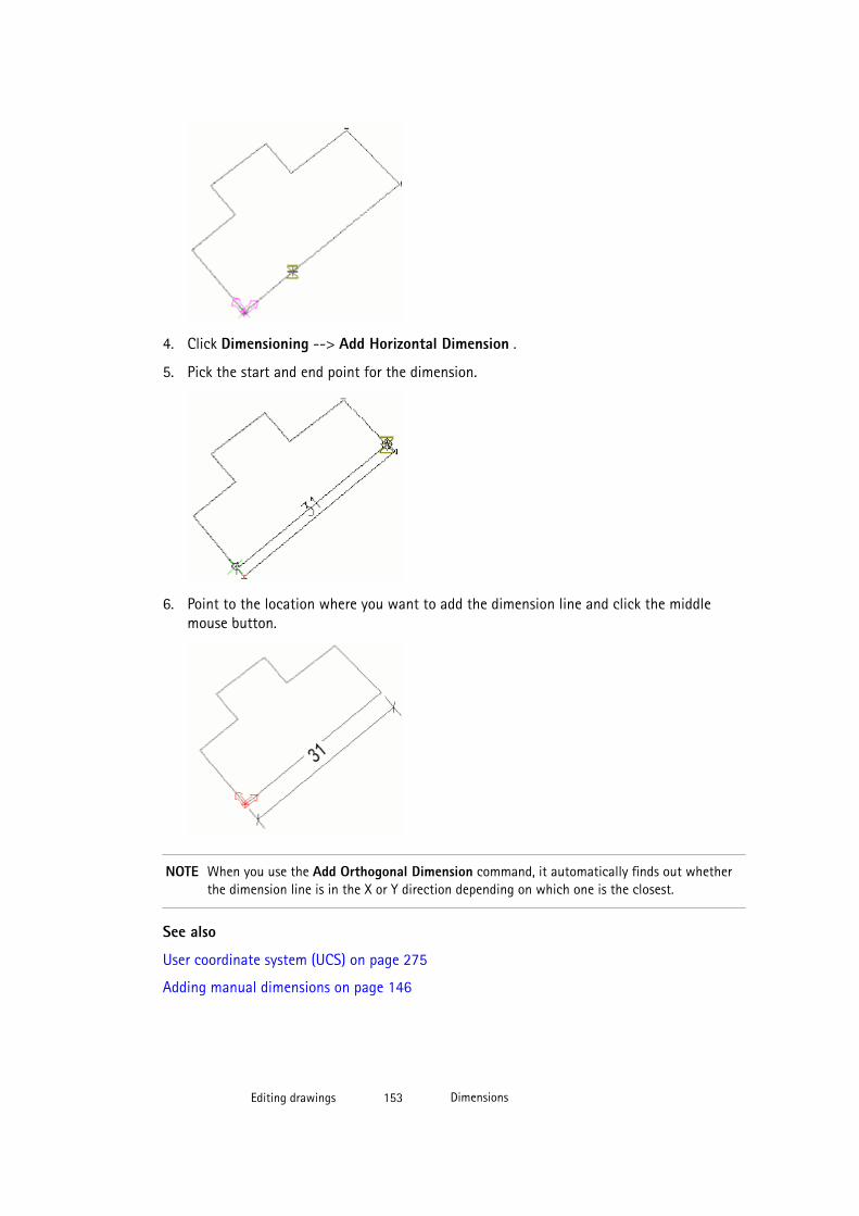
4. Click Dimensioning --> Add Horizontal Dimension .
5. Pick the start and end point for the dimension.
6. Point to the location where you want to add the dimension line and click the middlemouse button.
NOTE When you use the Add Orthogonal Dimension command, it automatically finds out whetherthe dimension line is in the X or Y direction depending on which one is the closest.
See also
User coordinate system (UCS) on page 275
Adding manual dimensions on page 146
Editing drawings 153 Dimensions

Adding tags to dimensions
You can add dimension tags to dimensions in an open drawing. You can add dimension tagsto single and combined dimensions.
Limitations:
• Rotation is not available for the middle dimension tags.
• The dimension tags are automatically updated according to model changes, when youupdate the drawing. If you want to disable the automatic update, you can freeze thedrawing or set the advanced option XS_INTELLIGENT_DRAWING_ALLOWED to FALSE. This advanced option affects all drawings.
To add dimension tags to a dimension:
1. Double-click the dimension.
2. Go to the Tags tab and select the locations where you want to add dimension tags.
You can add dimension tags above and below the dimension line to the left and right endof the line, to the dimension line ends, and in the middle of the dimension line below theline.
3. Click the ... buttons to go to the Tag Mark Properties dialog box.
You can also enter text directly in the A - G boxes.
4. Select the tag rotation. Each tag has an independent rotation setting, so you can rotatesome tags and leave others unrotated.
• Parallel to dimension line does not rotate the tag. This is the default value.
• Perpendicular to dimension line rotates the tag.
5. Include the elements that you want in the dimension tag.
The available elements are the same as those of the part, bolt, reinforcement and surfacetreatment marks.
6. Select the element frame type and color and the text color, font, and height.
7. Click OK.
8. If you want to show the part count in the tag, set Include part count in the tag to Yes.
Editing drawings 154 Dimensions

9. Use Exclude parts according to filter and select a predefined filter to remove some ofthe automatically created tag content.
In addition to the user-selectable elements, some of the dimension tag content isautomatically created based on the dimension end point locations. If you want to excludeunnecessary tag content for parts that are located in the same location as thedimensioning point, create suitable drawing view filter.
10. Click Modify.
Limitations
Below is an example of dimension tags.
Below is an example of an unrotated and a rotated dimension tag.
See also
Part mark elements on page 584
Bolt mark elements on page 586
Reinforcement and neighbor reinforcement mark elements on page 587
Surface treatment mark elements on page 590
Using superscript in text on page 194
Dimensions on page 145
Modifying dimension properties on page 171
Dimension and dimensioning properties on page 556
Example: Filtering out dimension tag content on page 156
Editing drawings 155 Dimensions
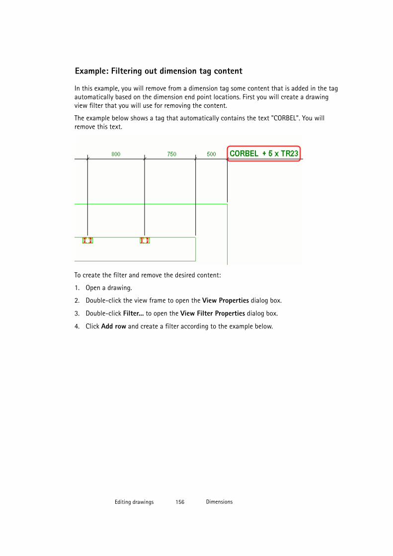
Example: Filtering out dimension tag content
In this example, you will remove from a dimension tag some content that is added in the tagautomatically based on the dimension end point locations. First you will create a drawingview filter that you will use for removing the content.
The example below shows a tag that automatically contains the text "CORBEL". You willremove this text.
To create the filter and remove the desired content:
1. Open a drawing.
2. Double-click the view frame to open the View Properties dialog box.
3. Double-click Filter... to open the View Filter Properties dialog box.
4. Click Add row and create a filter according to the example below.
Editing drawings 156 Dimensions
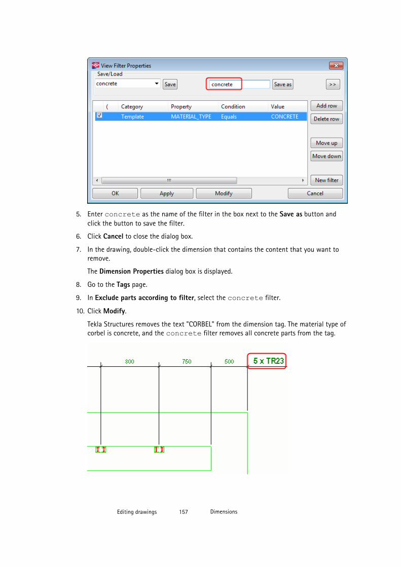
5. Enter concrete as the name of the filter in the box next to the Save as button andclick the button to save the filter.
6. Click Cancel to close the dialog box.
7. In the drawing, double-click the dimension that contains the content that you want toremove.
The Dimension Properties dialog box is displayed.
8. Go to the Tags page.
9. In Exclude parts according to filter, select the concrete filter.
10. Click Modify.
Tekla Structures removes the text "CORBEL" from the dimension tag. The material type ofcorbel is concrete, and the concrete filter removes all concrete parts from the tag.
Editing drawings 157 Dimensions
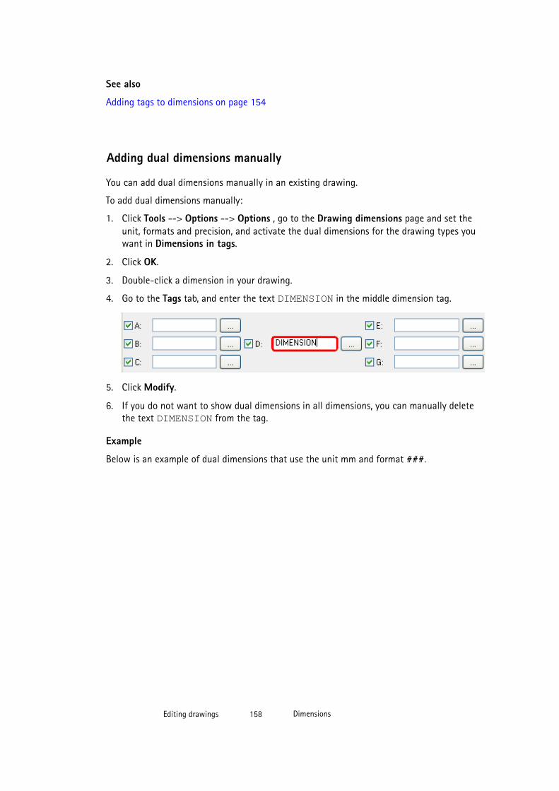
See also
Adding tags to dimensions on page 154
Adding dual dimensions manually
You can add dual dimensions manually in an existing drawing.
To add dual dimensions manually:
1. Click Tools --> Options --> Options , go to the Drawing dimensions page and set theunit, formats and precision, and activate the dual dimensions for the drawing types youwant in Dimensions in tags.
2. Click OK.
3. Double-click a dimension in your drawing.
4. Go to the Tags tab, and enter the text DIMENSION in the middle dimension tag.
5. Click Modify.
6. If you do not want to show dual dimensions in all dimensions, you can manually deletethe text DIMENSION from the tag.
Example
Below is an example of dual dimensions that use the unit mm and format ###.
Editing drawings 158 Dimensions
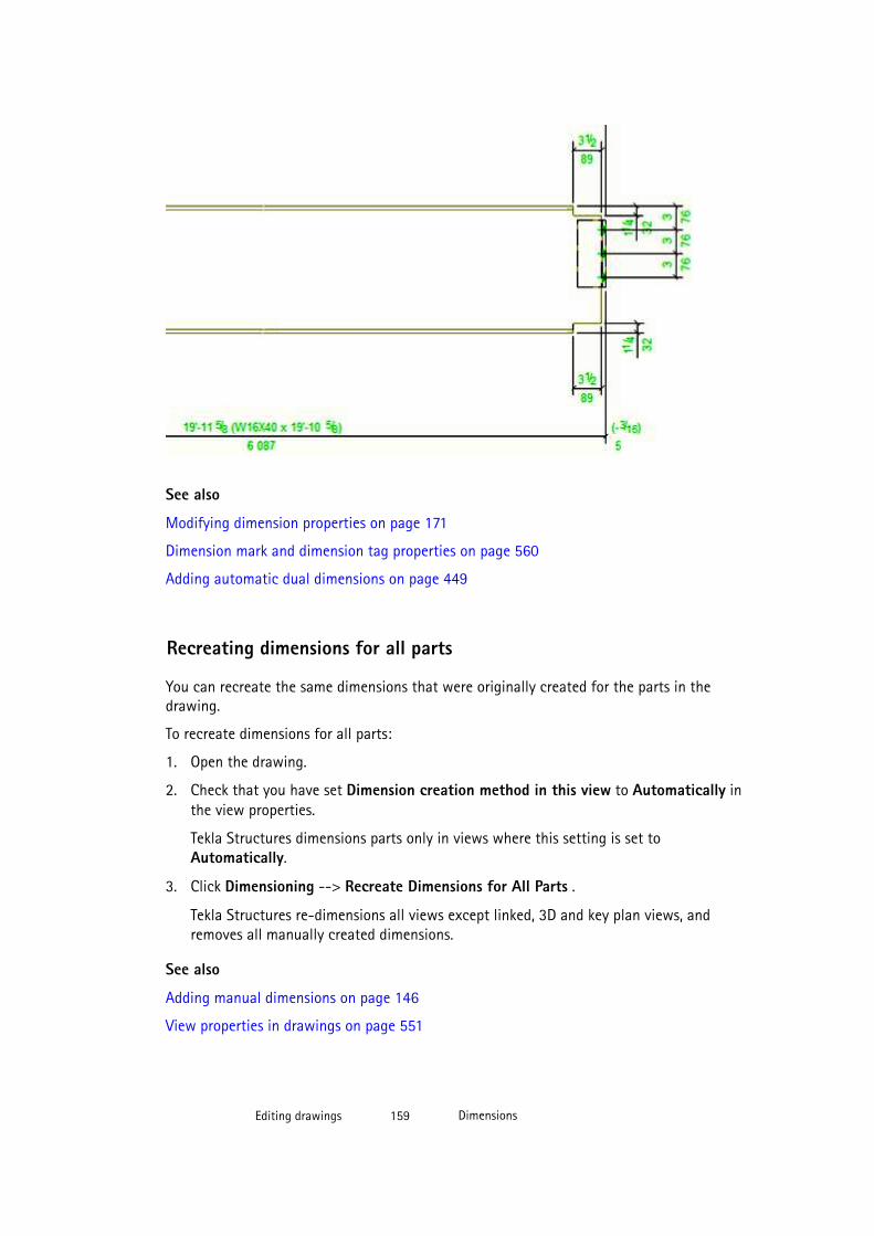
See also
Modifying dimension properties on page 171
Dimension mark and dimension tag properties on page 560
Adding automatic dual dimensions on page 449
Recreating dimensions for all parts
You can recreate the same dimensions that were originally created for the parts in thedrawing.
To recreate dimensions for all parts:
1. Open the drawing.
2. Check that you have set Dimension creation method in this view to Automatically inthe view properties.
Tekla Structures dimensions parts only in views where this setting is set toAutomatically.
3. Click Dimensioning --> Recreate Dimensions for All Parts .
Tekla Structures re-dimensions all views except linked, 3D and key plan views, andremoves all manually created dimensions.
See also
Adding manual dimensions on page 146
View properties in drawings on page 551
Editing drawings 159 Dimensions
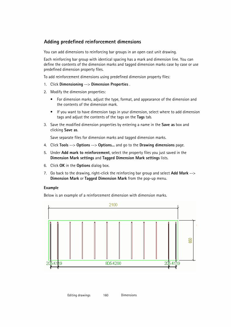
Adding predefined reinforcement dimensions
You can add dimensions to reinforcing bar groups in an open cast unit drawing.
Each reinforcing bar group with identical spacing has a mark and dimension line. You candefine the contents of the dimension marks and tagged dimension marks case by case or usepredefined dimension property files.
To add reinforcement dimensions using predefined dimension property files:
1. Click Dimensioning --> Dimension Properties .
2. Modify the dimension properties:
• For dimension marks, adjust the type, format, and appearance of the dimension andthe contents of the dimension mark.
• If you want to have dimension tags in your dimension, select where to add dimensiontags and adjust the contents of the tags on the Tags tab.
3. Save the modified dimension properties by entering a name in the Save as box andclicking Save as.
Save separate files for dimension marks and tagged dimension marks.
4. Click Tools --> Options --> Options... and go to the Drawing dimensions page.
5. Under Add mark to reinforcement, select the property files you just saved in theDimension Mark settings and Tagged Dimension Mark settings lists.
6. Click OK in the Options dialog box.
7. Go back to the drawing, right-click the reinforcing bar group and select Add Mark -->Dimension Mark or Tagged Dimension Mark from the pop-up menu.
Example
Below is an example of a reinforcement dimension with dimension marks.
Editing drawings 160 Dimensions
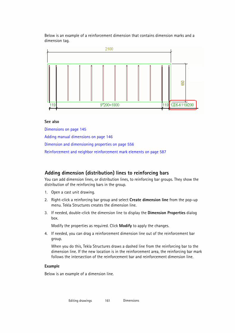
Below is an example of a reinforcement dimension that contains dimension marks and adimension tag.
See also
Dimensions on page 145
Adding manual dimensions on page 146
Dimension and dimensioning properties on page 556
Reinforcement and neighbor reinforcement mark elements on page 587
Adding dimension (distribution) lines to reinforcing barsYou can add dimension lines, or distribution lines, to reinforcing bar groups. They show thedistribution of the reinforcing bars in the group.
1. Open a cast unit drawing.
2. Right-click a reinforcing bar group and select Create dimension line from the pop-upmenu. Tekla Structures creates the dimension line.
3. If needed, double-click the dimension line to display the Dimension Properties dialogbox.
Modify the properties as required. Click Modify to apply the changes.
4. If needed, you can drag a reinforcement dimension line out of the reinforcement bargroup.
When you do this, Tekla Structures draws a dashed line from the reinforcing bar to thedimension line. If the new location is in the reinforcement area, the reinforcing bar markfollows the intersection of the reinforcement bar and reinforcement dimension line.
Example
Below is an example of a dimension line.
Editing drawings 161 Dimensions
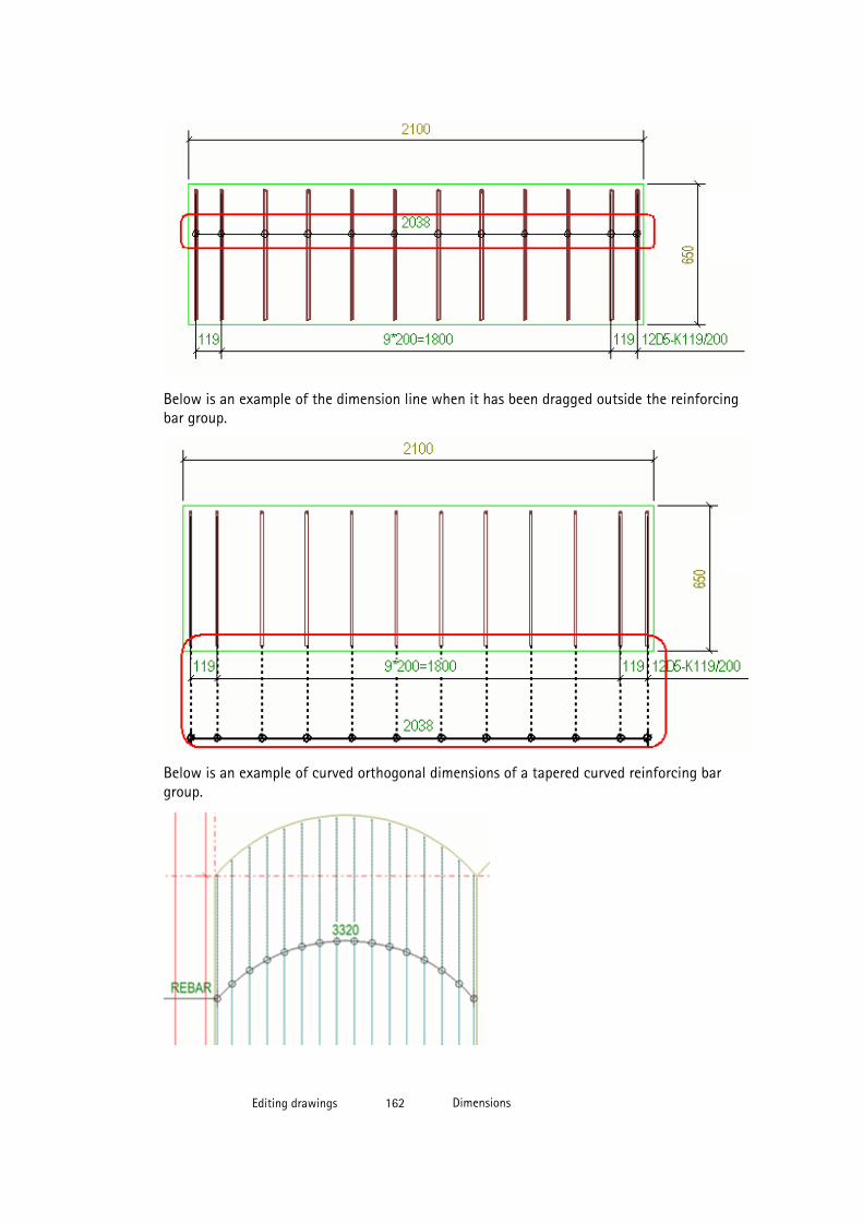
Below is an example of the dimension line when it has been dragged outside the reinforcingbar group.
Below is an example of curved orthogonal dimensions of a tapered curved reinforcing bargroup.
Editing drawings 162 Dimensions

Below is an example of curved dimensions of a radial reincofing bar group.
See also
Dimensions on page 145
Adding manual dimensions on page 146
Dimension and dimensioning properties on page 556
Dimensioning reinforcing bar groups
You can add dimensions to reinforcing bar groups using the RebarGroupDimensionPluginapplication.
Before you start using this feature, add the RebarGroupDimensionPlugin command to atoolbar through Tools --> Customize . Always add commands to the User menu and totoolbars in the modeling mode, otherwise they are not saved.
To add dimensions to reinforcing bar groups:
1. Select the reinforcing bar groups.
2. Press down Shift and click the Create RebarGroupDimensionPlugin command that youadded on a toolbar.
If you do not want to adjust any properties, just click the command.
3. Select the Annotation type.
Editing drawings 163 Dimensions
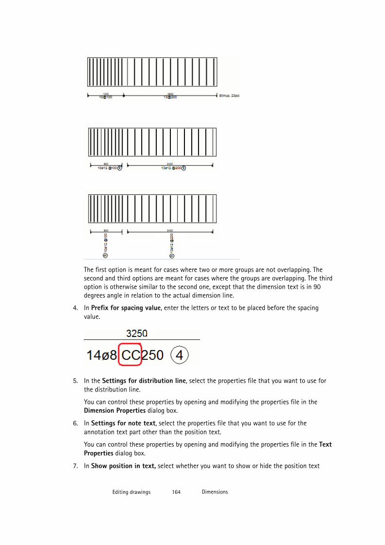
The first option is meant for cases where two or more groups are not overlapping. Thesecond and third options are meant for cases where the groups are overlapping. The thirdoption is otherwise similar to the second one, except that the dimension text is in 90degrees angle in relation to the actual dimension line.
4. In Prefix for spacing value, enter the letters or text to be placed before the spacingvalue.
5. In the Settings for distribution line, select the properties file that you want to use forthe distribution line.
You can control these properties by opening and modifying the properties file in theDimension Properties dialog box.
6. In Settings for note text, select the properties file that you want to use for theannotation text part other than the position text.
You can control these properties by opening and modifying the properties file in the TextProperties dialog box.
7. In Show position in text, select whether you want to show or hide the position text
Editing drawings 164 Dimensions
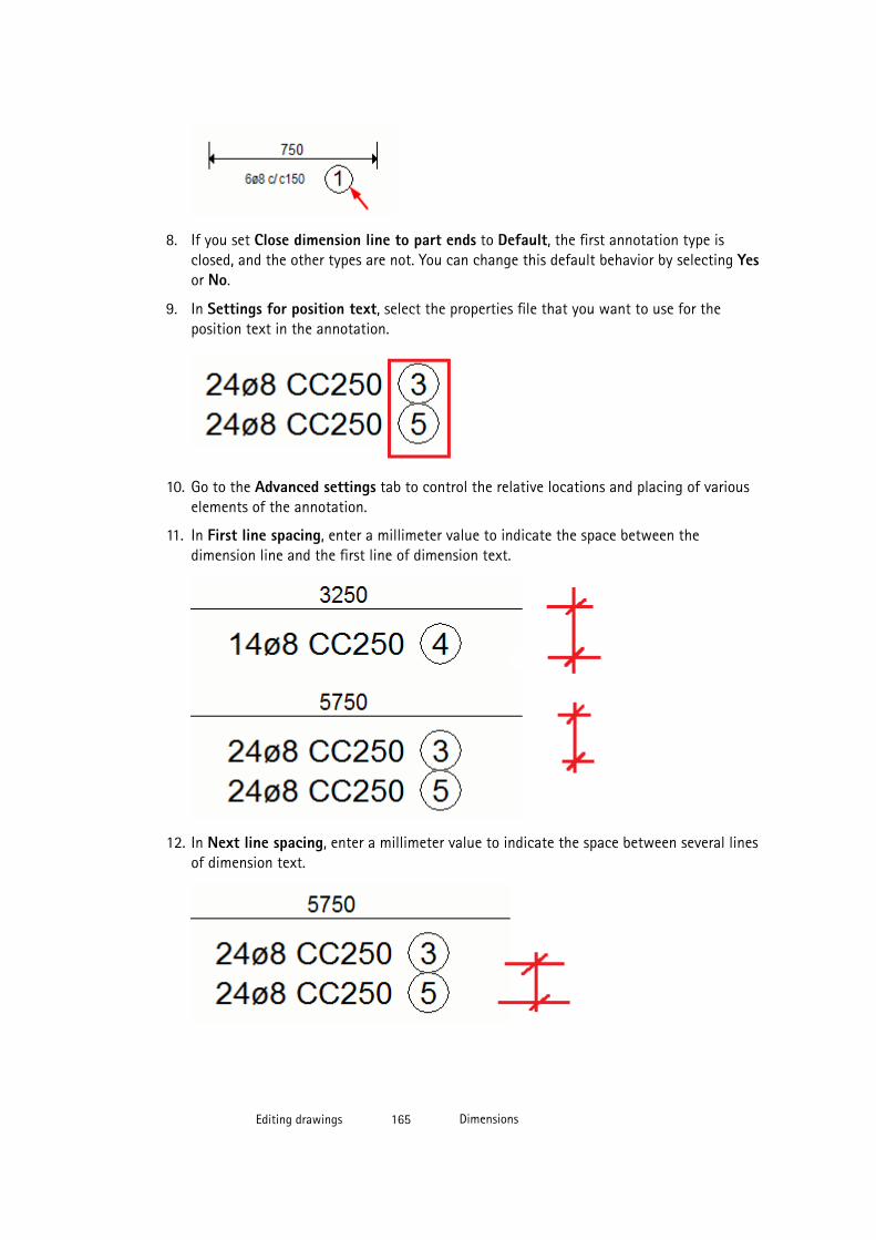
8. If you set Close dimension line to part ends to Default, the first annotation type isclosed, and the other types are not. You can change this default behavior by selecting Yesor No.
9. In Settings for position text, select the properties file that you want to use for theposition text in the annotation.
10. Go to the Advanced settings tab to control the relative locations and placing of variouselements of the annotation.
11. In First line spacing, enter a millimeter value to indicate the space between thedimension line and the first line of dimension text.
12. In Next line spacing, enter a millimeter value to indicate the space between several linesof dimension text.
Editing drawings 165 Dimensions
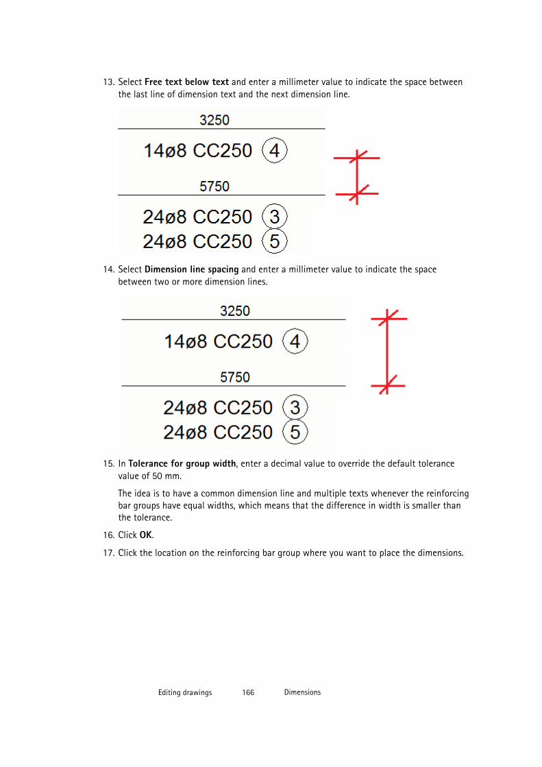
13. Select Free text below text and enter a millimeter value to indicate the space betweenthe last line of dimension text and the next dimension line.
14. Select Dimension line spacing and enter a millimeter value to indicate the spacebetween two or more dimension lines.
15. In Tolerance for group width, enter a decimal value to override the default tolerancevalue of 50 mm.
The idea is to have a common dimension line and multiple texts whenever the reinforcingbar groups have equal widths, which means that the difference in width is smaller thanthe tolerance.
16. Click OK.
17. Click the location on the reinforcing bar group where you want to place the dimensions.
Editing drawings 166 Dimensions
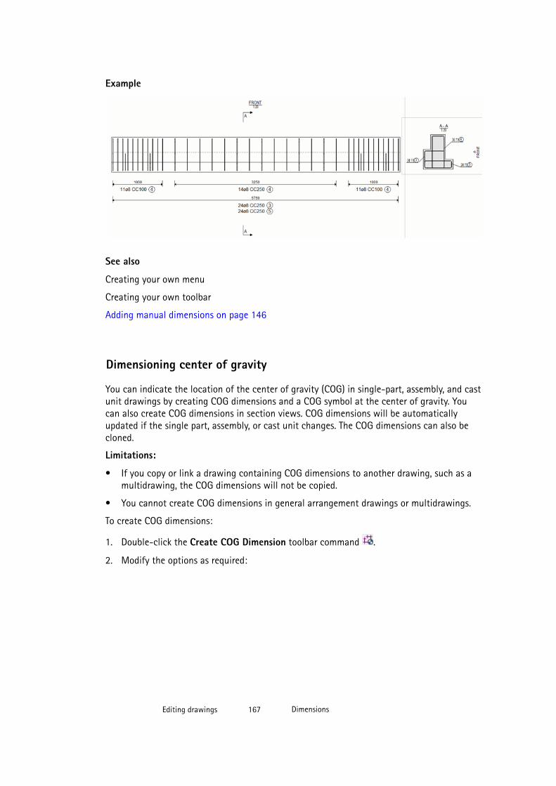
Example
See also
Creating your own menu
Creating your own toolbar
Adding manual dimensions on page 146
Dimensioning center of gravity
You can indicate the location of the center of gravity (COG) in single-part, assembly, and castunit drawings by creating COG dimensions and a COG symbol at the center of gravity. Youcan also create COG dimensions in section views. COG dimensions will be automaticallyupdated if the single part, assembly, or cast unit changes. The COG dimensions can also becloned.
Limitations:
• If you copy or link a drawing containing COG dimensions to another drawing, such as amultidrawing, the COG dimensions will not be copied.
• You cannot create COG dimensions in general arrangement drawings or multidrawings.
To create COG dimensions:
1. Double-click the Create COG Dimension toolbar command .
2. Modify the options as required:
Editing drawings 167 Dimensions
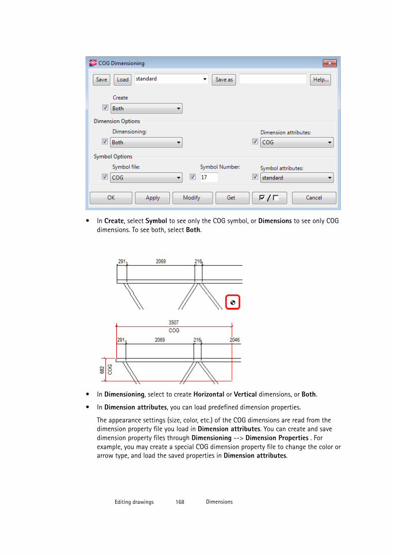
• In Create, select Symbol to see only the COG symbol, or Dimensions to see only COGdimensions. To see both, select Both.
• In Dimensioning, select to create Horizontal or Vertical dimensions, or Both.
• In Dimension attributes, you can load predefined dimension properties.
The appearance settings (size, color, etc.) of the COG dimensions are read from thedimension property file you load in Dimension attributes. You can create and savedimension property files through Dimensioning --> Dimension Properties . Forexample, you may create a special COG dimension property file to change the color orarrow type, and load the saved properties in Dimension attributes.
Editing drawings 168 Dimensions

• In Symbol Options, you can change the Symbol file in use and the symbol you wantto use for COG, and load predefined symbol properties.
You can access the symbol options only if you have selected Both or Symbol forCreate. The appearance settings (height, color, etc.) of the symbol are read from thesymbol properties file you load in Symbol attributes.
You can create and save symbol property files through Annotating --> Properties --> Symbols… . For example, you may create a special COG symbol properties file tochange the color and height of the symbol, and load the saved properties in Symbolattributes.
3. Click OK.
4. Pick the first point to specify the origin of the dimensions. The origin is the point fromwhich you want to measure the location of the center of gravity. This point must belocated within the view frame.
5. Pick the second point to place the dimensions. This point may fall outside the view frame.
Editing drawings 169 Dimensions
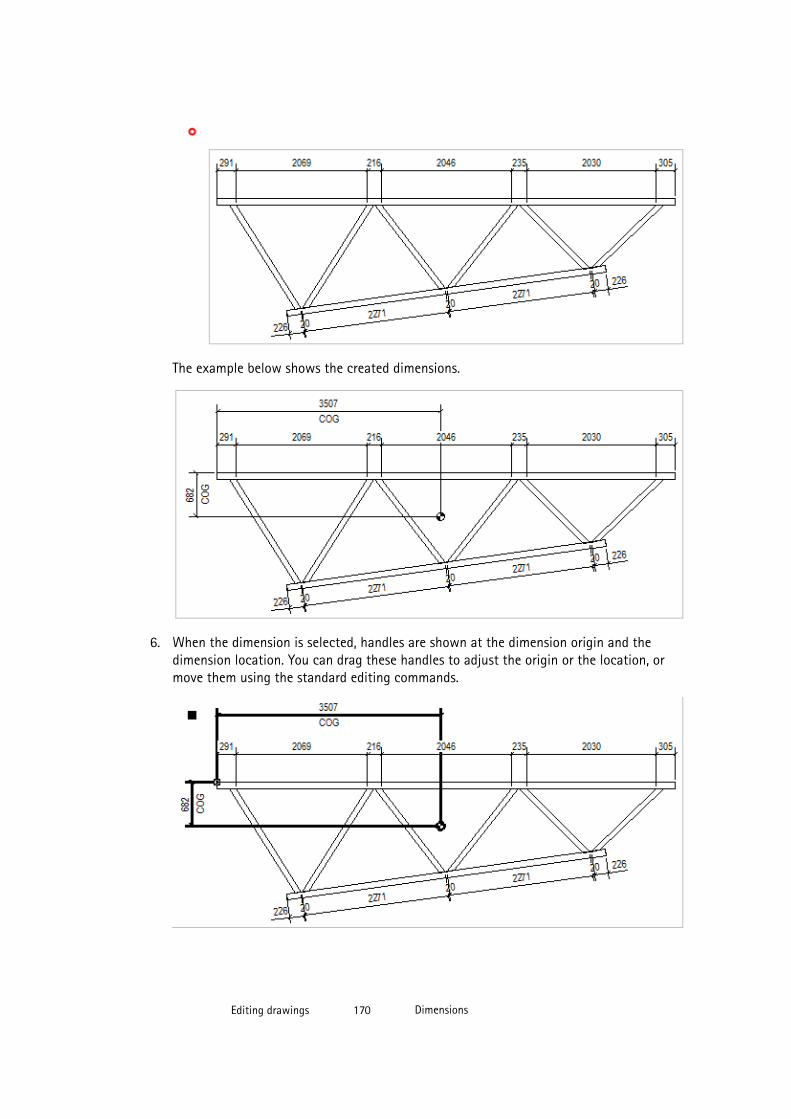
The example below shows the created dimensions.
6. When the dimension is selected, handles are shown at the dimension origin and thedimension location. You can drag these handles to adjust the origin or the location, ormove them using the standard editing commands.
Editing drawings 170 Dimensions
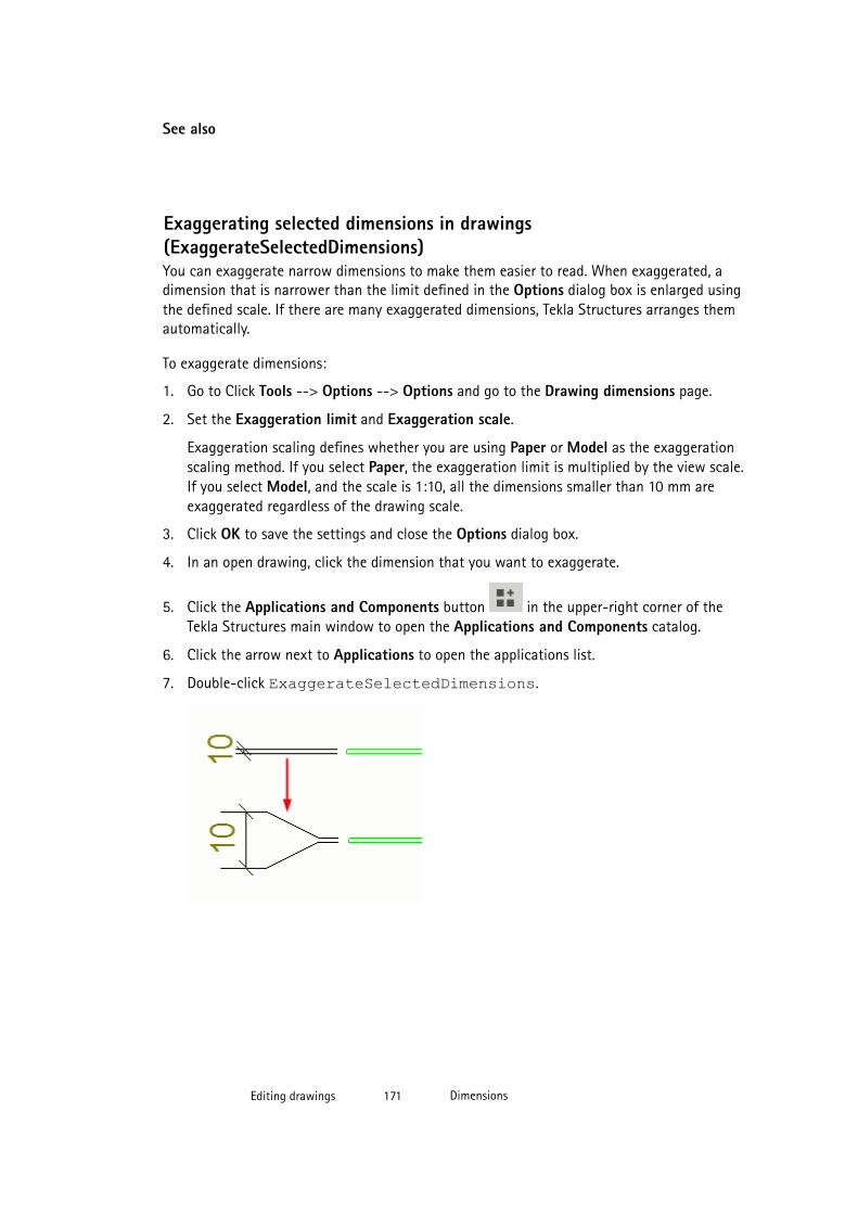
See also
Exaggerating selected dimensions in drawings(ExaggerateSelectedDimensions)You can exaggerate narrow dimensions to make them easier to read. When exaggerated, adimension that is narrower than the limit defined in the Options dialog box is enlarged usingthe defined scale. If there are many exaggerated dimensions, Tekla Structures arranges themautomatically.
To exaggerate dimensions:
1. Go to Click Tools --> Options --> Options and go to the Drawing dimensions page.
2. Set the Exaggeration limit and Exaggeration scale.
Exaggeration scaling defines whether you are using Paper or Model as the exaggerationscaling method. If you select Paper, the exaggeration limit is multiplied by the view scale.If you select Model, and the scale is 1:10, all the dimensions smaller than 10 mm areexaggerated regardless of the drawing scale.
3. Click OK to save the settings and close the Options dialog box.
4. In an open drawing, click the dimension that you want to exaggerate.
5. Click the Applications and Components button in the upper-right corner of theTekla Structures main window to open the Applications and Components catalog.
6. Click the arrow next to Applications to open the applications list.
7. Double-click ExaggerateSelectedDimensions.
Editing drawings 171 Dimensions

Modifying dimension properties
You can modify the properties of the dimensions in an open drawing.
To modify dimensions:
1. Double-click a dimension.
2. Switch all the check boxes off in the dialog box by clicking the on/off switch at the bottom of the dialog box.
3. Select only the check boxes next to the properties that you want to modify.
4. On the General tab, modify the dimension type, format, and placing settings.
For example, here you can set the dimension to be free or fixed. Free lets Tekla Structuresto decide the location and direction of the dimension. Fixed allows you to place thedimension at any point. For more information click the link in the See also section.
5. On the Appearance tab, modify the text, line and arrow settings.
For more information, click the link in the See also section.
6. On the Marks tab, modify the dimension mark contents and exaggeration settings.
Here you can also select whether you want to show plate side marks. for moreinformation, click the link in the See also section.
7. On the Marks tab, click the ... button next to Prefix or Posfix to add elements in thedimension mark and modify element appearance.
8. On the Tags tab, add dimension tags as required, and set the dimension tag rotation.
Here you can also select to include part count to dimension tags and select a filter thatremoves the desired default content from the tag. For more information, click the link inthe See also section.
9. Click Modify.
See also
General dimension properties on page 556
Dimension appearance properties on page 560
Dimension mark and dimension tag properties on page 560
Adding tags to dimensions on page 154
Dimension and dimensioning properties on page 556
Adding manual dimensions on page 146
Editing drawings 172 Dimensions
Adding dimension points in anchor bolt plans
You can add dimension points to dimensions inside the enlarged views in an open anchor boltplan.
Limitations: You cannot create new dimension lines that have dimension points inside boththe enlarged views and the plan view.
To add dimension points to the dimensions inside the enlarged views:
1. Select the enlarged view frame.
2. Select the dimension to modify.
3. Right-click and select Add dimension point.
See also
Creating anchor bolt plans using saved settings on page 60
Example: Dimensions in anchor bolt plans on page 476
Showing plate side marks
You can show plate side marks on dimension leader lines. The plate side marks indicatewhether the dimension point is to the face or center of the part, for example, a plate, web, orflange.
To create plate side marks:
1. Select Dimensioning --> Dimension Properties .
2. In the Dimension Properties dialog box, go to the Marks tab, set Type in Plate sidemarks to Specified to manually control the symbol and insert plate side mark symbols inthe drawing.
The option Automatic is available only in intelligent drawings, that is when the advancedoption XS_INTELLIGENT_DRAWING_ALLOWED is set to TRUE.
3. Modify the other properties of the plate side marks as required:
• You can select the left and right plate side mark.
• You can set the mark size.
• You can adjust the mark color.
• You can set the offset of the mark from the dimension line.
4. Click Modify.
Editing drawings 173 Dimensions
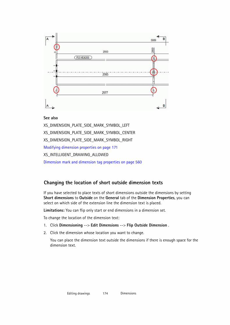
See also
XS_DIMENSION_PLATE_SIDE_MARK_SYMBOL_LEFT
XS_DIMENSION_PLATE_SIDE_MARK_SYMBOL_CENTER
XS_DIMENSION_PLATE_SIDE_MARK_SYMBOL_RIGHT
Modifying dimension properties on page 171
XS_INTELLIGENT_DRAWING_ALLOWED
Dimension mark and dimension tag properties on page 560
Changing the location of short outside dimension texts
If you have selected to place texts of short dimensions outside the dimensions by settingShort dimensions to Outside on the General tab of the Dimension Properties, you canselect on which side of the extension line the dimension text is placed.
Limitations: You can flip only start or end dimensions in a dimension set.
To change the location of the dimension text:
1. Click Dimensioning --> Edit Dimensions --> Flip Outside Dimension .
2. Click the dimension whose location you want to change.
You can place the dimension text outside the dimensions if there is enough space for thedimension text.
Editing drawings 174 Dimensions
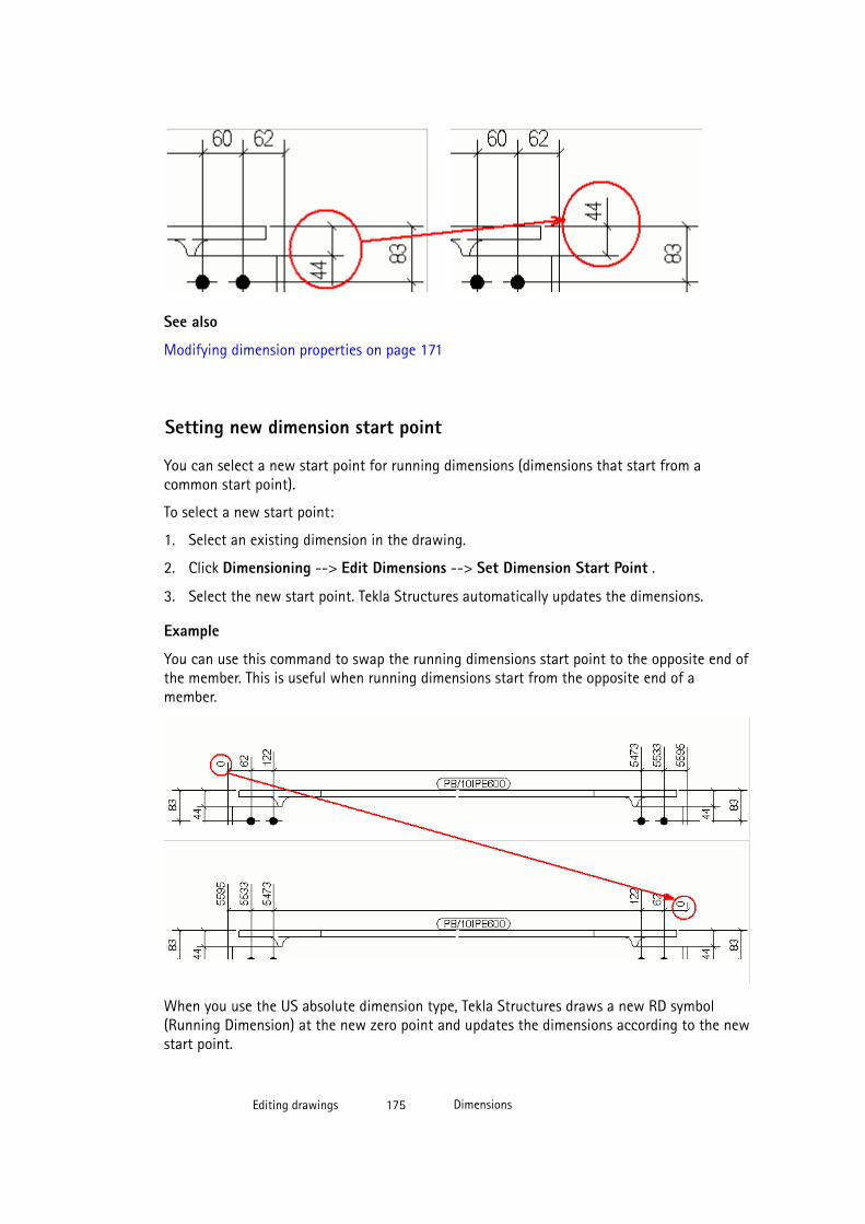
See also
Modifying dimension properties on page 171
Setting new dimension start point
You can select a new start point for running dimensions (dimensions that start from acommon start point).
To select a new start point:
1. Select an existing dimension in the drawing.
2. Click Dimensioning --> Edit Dimensions --> Set Dimension Start Point .
3. Select the new start point. Tekla Structures automatically updates the dimensions.
Example
You can use this command to swap the running dimensions start point to the opposite end ofthe member. This is useful when running dimensions start from the opposite end of amember.
When you use the US absolute dimension type, Tekla Structures draws a new RD symbol(Running Dimension) at the new zero point and updates the dimensions according to the newstart point.
Editing drawings 175 Dimensions
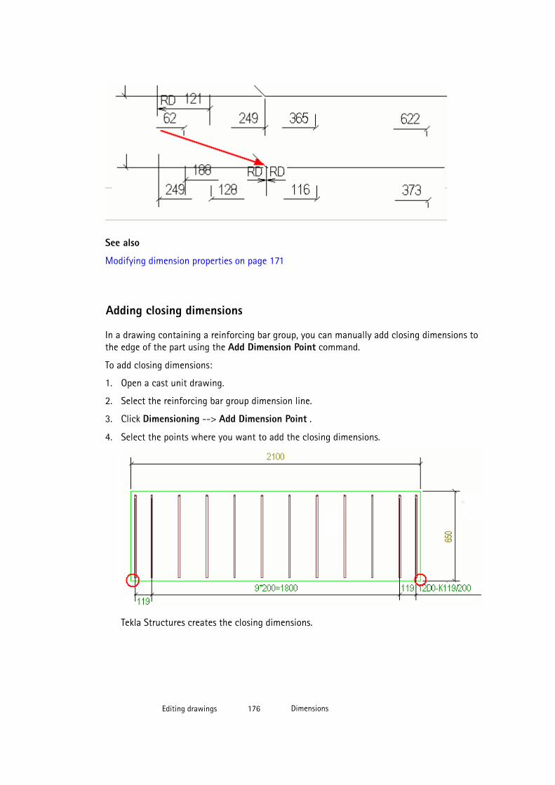
See also
Modifying dimension properties on page 171
Adding closing dimensions
In a drawing containing a reinforcing bar group, you can manually add closing dimensions tothe edge of the part using the Add Dimension Point command.
To add closing dimensions:
1. Open a cast unit drawing.
2. Select the reinforcing bar group dimension line.
3. Click Dimensioning --> Add Dimension Point .
4. Select the points where you want to add the closing dimensions.
Tekla Structures creates the closing dimensions.
Editing drawings 176 Dimensions
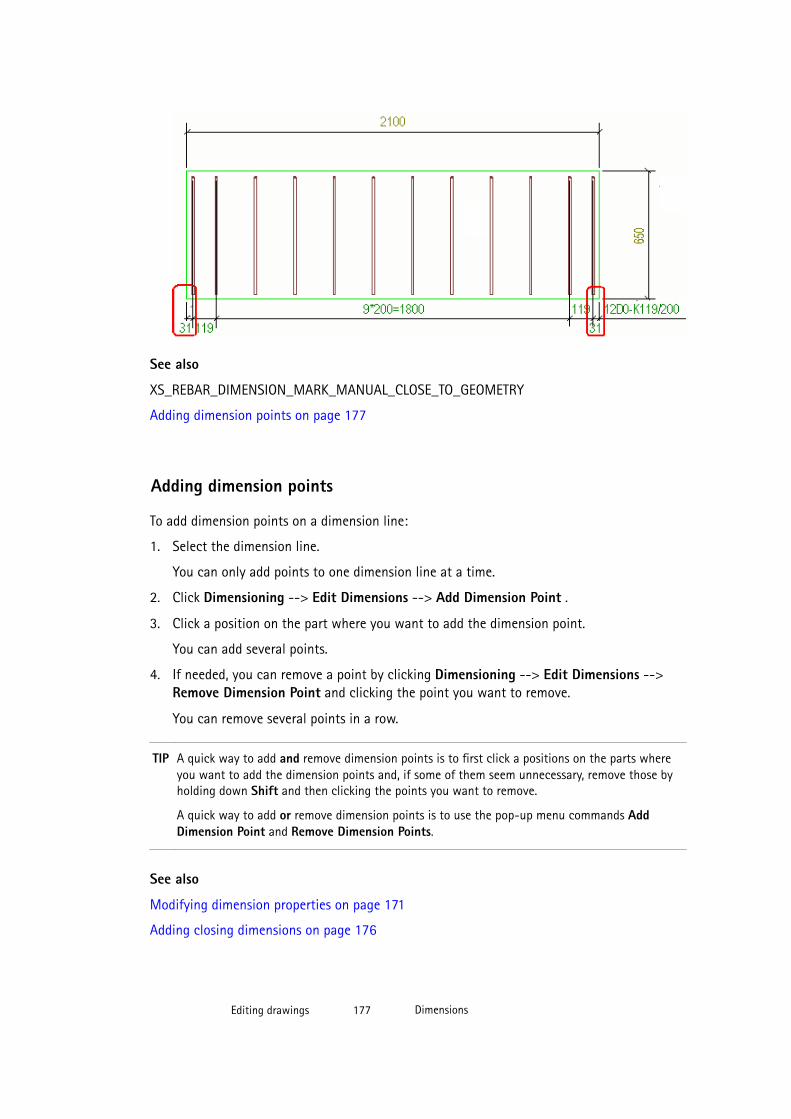
See also
XS_REBAR_DIMENSION_MARK_MANUAL_CLOSE_TO_GEOMETRY
Adding dimension points on page 177
Adding dimension points
To add dimension points on a dimension line:
1. Select the dimension line.
You can only add points to one dimension line at a time.
2. Click Dimensioning --> Edit Dimensions --> Add Dimension Point .
3. Click a position on the part where you want to add the dimension point.
You can add several points.
4. If needed, you can remove a point by clicking Dimensioning --> Edit Dimensions -->Remove Dimension Point and clicking the point you want to remove.
You can remove several points in a row.
TIP A quick way to add and remove dimension points is to first click a positions on the parts whereyou want to add the dimension points and, if some of them seem unnecessary, remove those byholding down Shift and then clicking the points you want to remove.
A quick way to add or remove dimension points is to use the pop-up menu commands AddDimension Point and Remove Dimension Points.
See also
Modifying dimension properties on page 171
Adding closing dimensions on page 176
Editing drawings 177 Dimensions
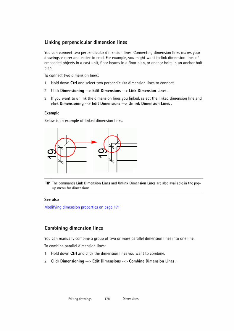
Linking perpendicular dimension lines
You can connect two perpendicular dimension lines. Connecting dimension lines makes yourdrawings clearer and easier to read. For example, you might want to link dimension lines ofembedded objects in a cast unit, floor beams in a floor plan, or anchor bolts in an anchor boltplan.
To connect two dimension lines:
1. Hold down Ctrl and select two perpendicular dimension lines to connect.
2. Click Dimensioning --> Edit Dimensions --> Link Dimension Lines .
3. If you want to unlink the dimension lines you linked, select the linked dimension line andclick Dimensioning --> Edit Dimensions --> Unlink Dimension Lines .
Example
Below is an example of linked dimension lines.
TIP The commands Link Dimension Lines and Unlink Dimension Lines are also available in the pop-up menu for dimensions.
See also
Modifying dimension properties on page 171
Combining dimension lines
You can manually combine a group of two or more parallel dimension lines into one line.
To combine parallel dimension lines:
1. Hold down Ctrl and click the dimension lines you want to combine.
2. Click Dimensioning --> Edit Dimensions --> Combine Dimension Lines .
Editing drawings 178 Dimensions

TIP You can also select Combine Dimension Lines from the pop-up menu.
See also
Modifying dimension properties on page 171
Dragging dimension marks
Dimension marks can be freely dragged to avoid overlapping dimensions and marks.
Ensure, that you have switched Smart Select on in Tools --> Options .
To drag dimension marks:
1. Select the dimension line.
If you do not select the dimension line first, dragging will move the whole dimension, notjust the dimension mark.
When you select the line, the dimension mark handle becomes visible.
Editing drawings 179 Dimensions
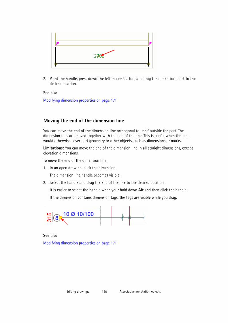
2. Point the handle, press down the left mouse button, and drag the dimension mark to thedesired location.
See also
Modifying dimension properties on page 171
Moving the end of the dimension line
You can move the end of the dimension line orthogonal to itself outside the part. Thedimension tags are moved together with the end of the line. This is useful when the tagswould otherwise cover part geometry or other objects, such as dimensions or marks.
Limitations: You can move the end of the dimension line in all straight dimensions, exceptelevation dimensions.
To move the end of the dimension line:
1. In an open drawing, click the dimension.
The dimension line handle becomes visible.
2. Select the handle and drag the end of the line to the desired position.
It is easier to select the handle when your hold down Alt and then click the handle.
If the dimension contains dimension tags, the tags are visible while you drag.
See also
Modifying dimension properties on page 171
Editing drawings 180 Associative annotation objects

4.5 Associative annotation objectsMarks, dimensions, and associative notes are associative annotation objects. An associativeannotation object updates according to the changes made in a model object in the model.Other objects are also associative if they have associativity points.
Other objects will also become associative if snap to a model object when you create them.For example, in texts, the content does not change when the model changes but theassociativity point may change. Another example is a line: if you snap to a part edge whenyou create a line, the line will get an associativity point and move with the part if the partchanges.
In addition to the annotation objects created in a drawing based on the drawing propertiesat drawing creation, you can also add new ones in an open drawing.
See also
Drawing objects on page 17
Dimensions on page 145
Adding part marks on page 181
Adding weld marks on page 223
Adding level marks on page 182
Adding associative notes on page 183
Modifying associative annotation object properties on page 184
Updating marks on page 185
Change symbols in drawings on page 186
Merging marks on page 189
Dragging the mark and associative note leader line base point on page 190
Adding part marks
In an open drawing, you can add part marks for all building objects, surface treatment andconnections, or for the selected ones only. For each view, Tekla Structures creates the marksaccording to the mark properties in the view mark properties dialog box.
To add part marks, do one of the following:
To Do this
Add part marks for all parts Click Annotating --> Add Part Marks --> For All Parts .
If you have deleted marks manually from the drawing, thiscommand will not create the marks, and you will have to createthem manually part by part.
Add part marks for selectedparts
1. Select the parts.
Editing drawings 181 Associative annotation objects
To Do this2. Click Annotating --> Add Part Marks --> For Selected
Parts
3. If the part mark does not contain any elements in thedrawing view properties, the Part Mark Properties dialogbox is displayed, and you can select the elements to beincluded in the part mark.
Add elements and click Modify.
TIP Alternatively, you can right-click the parts and select the appropriate mark creationcommand from the pop-up menu.
TIP Use orthogonal snapping in marks and associative notes with leader lines. For example,you can use it for placing your marks and notes in a more consistent way in exactlocations. When you start dragging a mark or note from a leader line end handle andyou have orthogonal snapping on (O or Tools --> Ortho ), the leader line end handlelocks to the closes orthogonal point in the drawing (0, 45, 90, 135, 180 degrees).
See also
Associative annotation objects on page 180
Modifying view-level drawing properties on page 327
Modifying drawing properties of an existing drawing on page 326
Modifying associative annotation object properties on page 184
Mark elements on page 583
Drawing settings on page 544
Adding level marks
A level mark is an associative annotation object that represents the elevation of a point. Inaddition to the automatic elevation dimensions that you can define in the drawing propertiesbefore creating the drawing, and the elevation information in the grid labels added in themodel, you can also add level marks in your drawing to ensure that the dimensions arecorrect.
To add level marks:
1. Open the drawing.
2. Hold down Shift and click Annotating --> Add Level Mark to open the Level MarkProperties dialog box.
3. Enter or modify the content and the appearance of the level mark.
4. Click Apply or OK to save the properties.
Editing drawings 182 Associative annotation objects
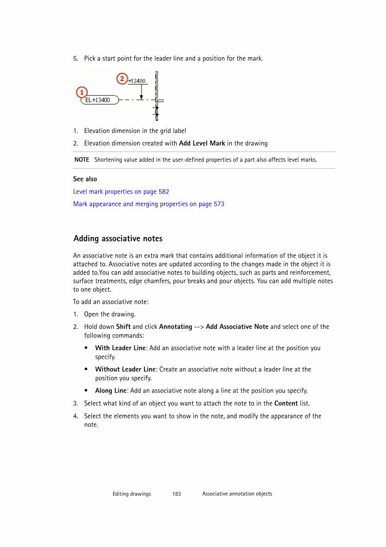
5. Pick a start point for the leader line and a position for the mark.
1. Elevation dimension in the grid label
2. Elevation dimension created with Add Level Mark in the drawing
NOTE Shortening value added in the user-defined properties of a part also affects level marks.
See also
Level mark properties on page 582
Mark appearance and merging properties on page 573
Adding associative notes
An associative note is an extra mark that contains additional information of the object it isattached to. Associative notes are updated according to the changes made in the object it isadded to.You can add associative notes to building objects, such as parts and reinforcement,surface treatments, edge chamfers, pour breaks and pour objects. You can add multiple notesto one object.
To add an associative note:
1. Open the drawing.
2. Hold down Shift and click Annotating --> Add Associative Note and select one of thefollowing commands:
• With Leader Line: Add an associative note with a leader line at the position youspecify.
• Without Leader Line: Create an associative note without a leader line at theposition you specify.
• Along Line: Add an associative note along a line at the position you specify.
3. Select what kind of an object you want to attach the note to in the Content list.
4. Select the elements you want to show in the note, and modify the appearance of thenote.
Editing drawings 183 Associative annotation objects
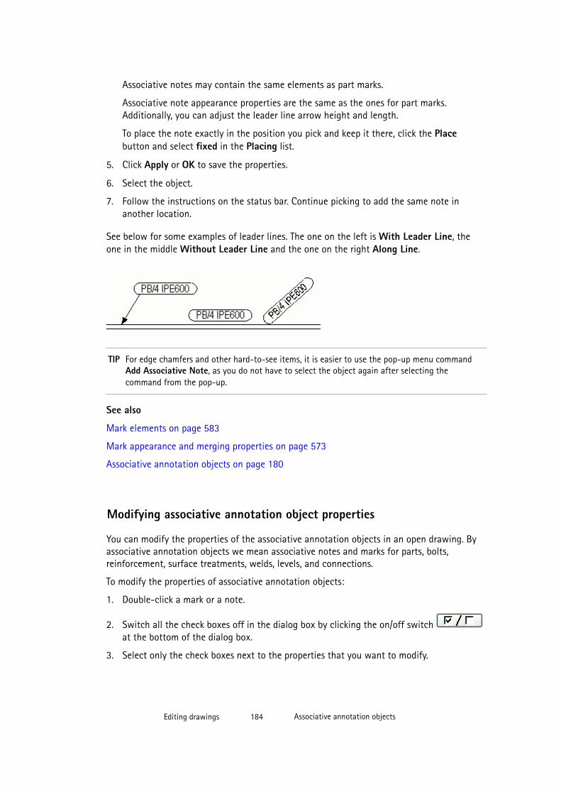
Associative notes may contain the same elements as part marks.
Associative note appearance properties are the same as the ones for part marks.Additionally, you can adjust the leader line arrow height and length.
To place the note exactly in the position you pick and keep it there, click the Placebutton and select fixed in the Placing list.
5. Click Apply or OK to save the properties.
6. Select the object.
7. Follow the instructions on the status bar. Continue picking to add the same note inanother location.
See below for some examples of leader lines. The one on the left is With Leader Line, theone in the middle Without Leader Line and the one on the right Along Line.
TIP For edge chamfers and other hard-to-see items, it is easier to use the pop-up menu commandAdd Associative Note, as you do not have to select the object again after selecting thecommand from the pop-up.
See also
Mark elements on page 583
Mark appearance and merging properties on page 573
Associative annotation objects on page 180
Modifying associative annotation object properties
You can modify the properties of the associative annotation objects in an open drawing. Byassociative annotation objects we mean associative notes and marks for parts, bolts,reinforcement, surface treatments, welds, levels, and connections.
To modify the properties of associative annotation objects:
1. Double-click a mark or a note.
2. Switch all the check boxes off in the dialog box by clicking the on/off switch at the bottom of the dialog box.
3. Select only the check boxes next to the properties that you want to modify.
Editing drawings 184 Associative annotation objects
4. Add missing elements in the mark on the Content tab and change the elementproperties. For more information about the mark elements and mark properties, click thelinks in the See also section.
5. Adjust the mark frame and leader line settings.
For more information about mark appearance properties, click the link in the See alsosection.
6. To exactly place the mark in the position you pick and keep it there, click the Place...button and select fixed in the Placing list.
For more information about the placement settings, click the link in the See also section.
7. Leave the dialog box open, select all the marks that you want to change, and clickModify to apply the changes in all the selected marks.
TIP To modify the properties of the weld marks of welds that you added in the model, you need tomodify the weld in the model. When you number the model, the weld marks are updated in thedrawings.
See also
Associative annotation objects on page 180
Mark properties on page 573
Mark elements on page 583
Mark appearance and merging properties on page 573
Defining placement settings for annotation objects on page 362
Updating marks
You can update part marks and weld marks in an open drawing. Normally part marks andweld marks are up to date when you open the drawing. Updating is needed in frozendrawings.
To update marks, do one of the following:
To Do this
Update all part marks Click Annotating --> Update Marks --> All Part Marks .
Update selected part marks 1. Select the part marks you want to update.
2. Click Annotating --> Update Marks --> Selected PartMarks .
Editing drawings 185 Associative annotation objects
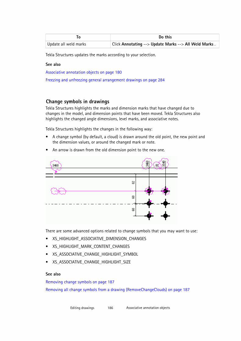
To Do this
Update all weld marks Click Annotating --> Update Marks --> All Weld Marks .
Tekla Structures updates the marks according to your selection.
See also
Associative annotation objects on page 180
Freezing and unfreezing general arrangement drawings on page 284
Change symbols in drawingsTekla Structures highlights the marks and dimension marks that have changed due tochanges in the model, and dimension points that have been moved. Tekla Structures alsohighlights the changed angle dimensions, level marks, and associative notes.
Tekla Structures highlights the changes in the following way:
• A change symbol (by default, a cloud) is drawn around the old point, the new point andthe dimension values, or around the changed mark or note.
• An arrow is drawn from the old dimension point to the new one.
There are some advanced options related to change symbols that you may want to use:
• XS_HIGHLIGHT_ASSOCIATIVE_DIMENSION_CHANGES
• XS_HIGHLIGHT_MARK_CONTENT_CHANGES
• XS_ASSOCIATIVE_CHANGE_HIGHLIGHT_SYMBOL
• XS_ASSOCIATIVE_CHANGE_HIGHLIGHT_SIZE
See also
Removing change symbols on page 187
Removing all change symbols from a drawing (RemoveChangeClouds) on page 187
Editing drawings 186 Associative annotation objects
Removing change symbols
After you have checked all the change symbols that Tekla Structures has created, you canremove all of them or just the selected ones.
To remove change symbols, do one of the following:
To Do this
Remove all dimension change symbols Click Dimensioning --> Review Dimensions --> RemoveDimension Change Symbol --> All .
Remove the selected dimensionchange symbols
1. Select the change symbols you want to remove.
2. Click Dimensioning --> Review Dimensions -->Remove Dimension Change Symbol --> Single .
Remove all mark change symbols Click Annotating --> Review Marks --> Remove MarkChange Symbol --> All .
Remove the selected mark changesymbols
1. Select the change symbols you want to remove.
2. Click Annotating --> Review Marks --> RemoveMark Change Symbol --> Single .
Remove all associative note changesymbols
Click Annotating --> Review Marks --> RemoveAssociative Note Change Symbol --> All .
Remove the selected associative notechange symbols
1. Select the change symbols you want to remove.
2. Click Annotating --> Review Marks --> RemoveAssociative Note Change Symbol --> Single .
See also
Change symbols in drawings on page 186
Removing all change symbols from a drawing (RemoveChangeClouds)You can remove dimension change symbols, mark change symbols and associative notechange symbols in one go from an open drawing using the RemoveChangeCloudsmacro.
To remove all change symbols from a drawing that has a lot of different kinds of changesymbols:
1. Open the drawing.
2. Click the Applications and Components button in the upper-right corner of theTekla Structures main window to open the Applications and Components catalog.
3. Click the arrow next to Applications to open the applications list.
Editing drawings 187 Associative annotation objects

4. Double-click RemoveChangeClouds.
Tekla Structures removes all change symbols.
Example
The first image shows an example of a mark change symbol after a material change, and of adimension change symbol after a change in the size of the part.
The second image shows the dimension text and the mark after running the macro.
Editing drawings 188 Associative annotation objects
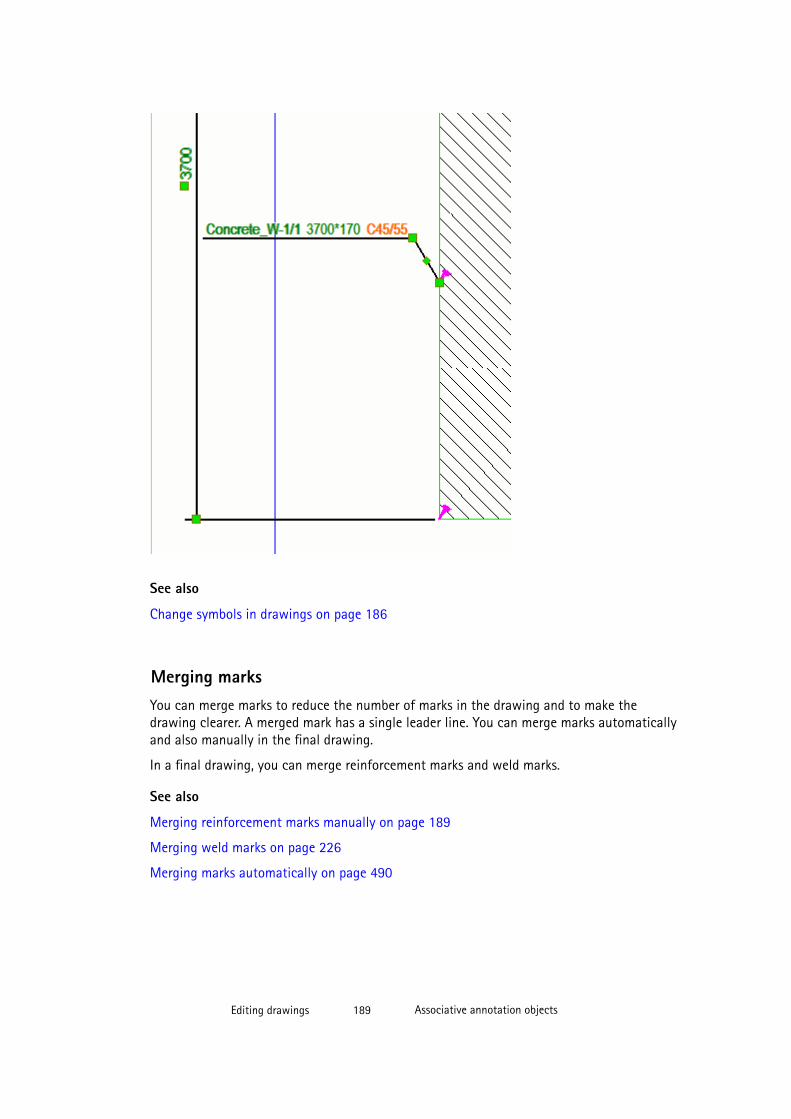
See also
Change symbols in drawings on page 186
Merging marksYou can merge marks to reduce the number of marks in the drawing and to make thedrawing clearer. A merged mark has a single leader line. You can merge marks automaticallyand also manually in the final drawing.
In a final drawing, you can merge reinforcement marks and weld marks.
See also
Merging reinforcement marks manually on page 189
Merging weld marks on page 226
Merging marks automatically on page 490
Editing drawings 189 Associative annotation objects

Merging reinforcement marks manually
To manually merge reinforcement marks in a drawing:
1. Click Annotating --> Properties --> Merged Reinforcement Mark... .
2. Modify mark properties as required.
3. Select the marks to merge in the drawing.
4. Right-click and select Merge marks from the pop-up menu.
5. If needed, you can split the merged marks by selecting the marks to split, right-clickingand selecting Split marks.
See also
Merging reinforcement marks automatically on page 493
Dragging the mark and associative note leader line base point
You can change the place of the mark and associative note leader line base point.
Ensure that you have switched Smart Select on in Tools --> Options to drag and drop byhandles without selecting them first.
Limitations:
• If the base point is originally on a line, you can drag it along that line.
• If the base point is originally inside a part, you can drag the base point inside that part.
To drag the leader line base point:
1. Click the leader line.
2. Hold down the left mouse button and drag the base point to a new location.
Limitations
See also
Associative annotation objects on page 180
Leader line types on page 576
Creating and using customized leader line arrows
If you do not find a suitable leader line arrow in the Arrow list in the Mark Properties dialogbox, you can add an arrow of your own.
First you will create the arrow symbol in the Symbol Editor, and save the created symbol inthe arrow.sym file. Then you need to add the position of the new symbol in the
Editing drawings 190 Associative annotation objects
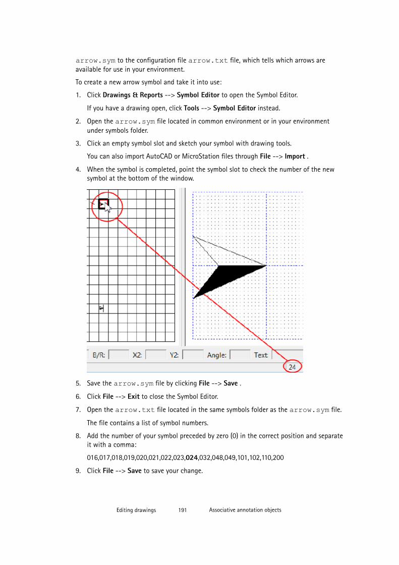
arrow.sym to the configuration file arrow.txt file, which tells which arrows areavailable for use in your environment.
To create a new arrow symbol and take it into use:
1. Click Drawings & Reports --> Symbol Editor to open the Symbol Editor.
If you have a drawing open, click Tools --> Symbol Editor instead.
2. Open the arrow.sym file located in common environment or in your environmentunder symbols folder.
3. Click an empty symbol slot and sketch your symbol with drawing tools.
You can also import AutoCAD or MicroStation files through File --> Import .
4. When the symbol is completed, point the symbol slot to check the number of the newsymbol at the bottom of the window.
5. Save the arrow.sym file by clicking File --> Save .
6. Click File --> Exit to close the Symbol Editor.
7. Open the arrow.txt file located in the same symbols folder as the arrow.sym file.
The file contains a list of symbol numbers.
8. Add the number of your symbol preceded by zero (0) in the correct position and separateit with a comma:
016,017,018,019,020,021,022,023,024,032,048,049,101,102,110,200
9. Click File --> Save to save your change.
Editing drawings 191 Associative annotation objects
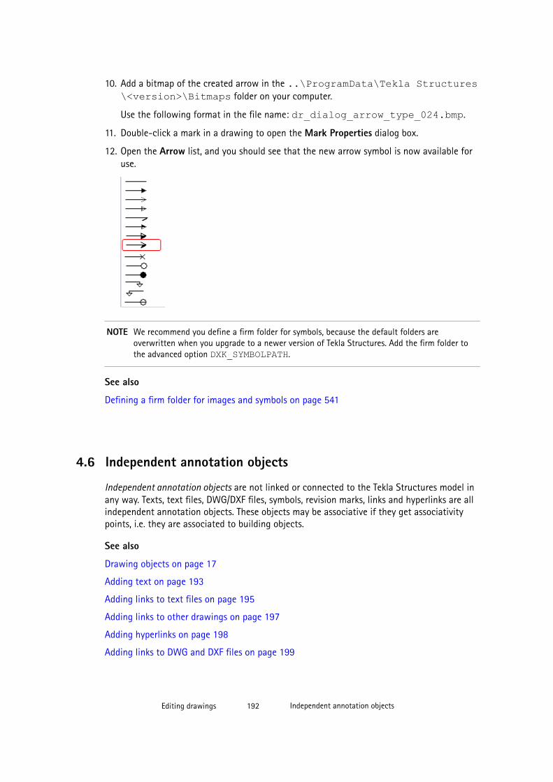
10. Add a bitmap of the created arrow in the ..\ProgramData\Tekla Structures\<version>\Bitmaps folder on your computer.
Use the following format in the file name: dr_dialog_arrow_type_024.bmp.
11. Double-click a mark in a drawing to open the Mark Properties dialog box.
12. Open the Arrow list, and you should see that the new arrow symbol is now available foruse.
NOTE We recommend you define a firm folder for symbols, because the default folders areoverwritten when you upgrade to a newer version of Tekla Structures. Add the firm folder tothe advanced option DXK_SYMBOLPATH.
See also
Defining a firm folder for images and symbols on page 541
4.6 Independent annotation objects
Independent annotation objects are not linked or connected to the Tekla Structures model inany way. Texts, text files, DWG/DXF files, symbols, revision marks, links and hyperlinks are allindependent annotation objects. These objects may be associative if they get associativitypoints, i.e. they are associated to building objects.
See also
Drawing objects on page 17
Adding text on page 193
Adding links to text files on page 195
Adding links to other drawings on page 197
Adding hyperlinks on page 198
Adding links to DWG and DXF files on page 199
Editing drawings 192 Independent annotation objects

Adding revision marks on page 200
Adding symbols in drawings on page 246
Modifying the properties of independent annotation objects on page 201
Adding text
You can add text in the drawings.
To add text:
1. Hold down Shift and click Annotating --> Add Text and then select one of thefollowing commands to create a single line or multiple lines of text:
• Text: Add text without a leader line at the position you pick.
• Text with Leader Line: Add text with a leader line at the position you pick.
• Text along Line: Add text along a line at the position you pick.
• Along Line, Arrow at End Point: Add text along a line at the position you pick. Anarrow is inserted at the second position you pick.
• Along Line, Arrow at Start Point: Add text along a line at the position you pick. Anarrow is inserted at the first position you pick.
2. Enter the text in the Text box.
Press Enter to make a line break.
3. Modify the text color, height, font, angle and alignment as required.
4. Select a frame type, leader line and color.
5. Select the leader line arrow type and size.
6. To exactly place the text in the position you pick, and keep it there, click the Place...button and select fixed in the Placing list.
7. Click OK or Apply.
8. Pick the point where you want to place the text. Depending on the command, you haveto pick one to three times.
Text is aligned to left by default. Line spacing is automatically adjusted by the font sizeyou select.
You can continue picking to add the same line of text in another location.
See below for examples of the different text options. From left: Text; Text with Leader Line;Text along Line; Along Line, Arrow at End Point; and Along Line, Arrow at Start Point.
Editing drawings 193 Independent annotation objects

TIP You can drag the base point of the text leader line freely after adding the text.
See also
Independent annotation objects on page 192
Using superscript in text
You can use superscript in texts in all your text objects, dimension marks, other marks andassociative notes.
Before you can use superscript, set the advanced option XS_SUPERSCRIPT_USED_IN_DRAWING_TEXTS to TRUE.
To use superscript text:
1. Open the properties dialog box of the text object, mark or associative note.
2. Do one of the following:
• For text objects, enter the desired text in the Text box.
• For marks and associative notes, open the Mark Content - text dialog box bydouble-clicking Text in the Available elements list and enter the desired text in theText box.
3. Enter circumflexes (^) around the characters that you want to have in superscript.
4. Click Modify or OK and Modify as required.
Example
This example shows how the superscript is entered in the Text box and what it looks like inthe text.
See also
Adding text on page 193
Editing drawings 194 Independent annotation objects
Associative annotation objects on page 180
Dimensions on page 145
XS_SUPERSCRIPT_USED_IN_DRAWING_TEXTS
Adding links to text filesYou can insert text inside a frame in a drawing by creating a link to a .txt or .rtf file.Tekla Structures adds the text using some basic formatting settings you can set in the fileitself and some of the properties in the Text File Properties dialog box. If you change thetext in the file, it will change in all drawings containing a link to the text file.
To add a link to a text file:
1. Create the text file.
You can add basic formatting to the file, such as bold and italics, and set a specific font.You can also use bulleted lists with hyphens and circular bullets, and numbered lists.When you add the text link, Tekla Structures preserves the formatting settings.
Tekla Structures colors will always be shown correctly. If you use in the .rft file a colorthat is not supported in Tekla Structures, then the closest Tekla Structures color will beused.
Nested lists are not supported.
2. Open the drawing where you want to add the text file.
3. Click Annotating --> Add Text --> From Text File .
4. Set the text height.
Other text settings are taken from the text file.
5. Set the frame line type and color.
6. Select if you want to scale the text:
• Scale to fit: You only need to pick the upper left corner of the frame when placingthe text. Tekla Structures inserts the object in its original size. In this case, when youchange the text frame size by dragging from the handles, the text does not wrap, andthe font scales automatically.
• No scaling: You need to pick two points to define the frame when placing the text.Tekla Structures adjusts the object size to fit the frame. The text wraps when youchange the size of the frame by dragging the handles. The minimum width of the boxis defined by the longest word.
7. Browse for the file.
8. Click OK or Apply.
9. Pick one or two points in the drawing to indicate the corners of the text file frame.
Tekla Structures adds the link to the text file.
Editing drawings 195 Independent annotation objects
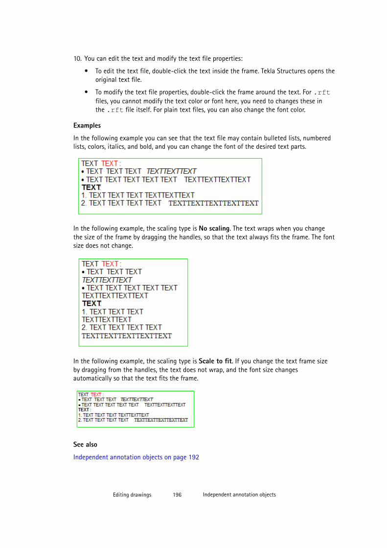
10. You can edit the text and modify the text file properties:
• To edit the text file, double-click the text inside the frame. Tekla Structures opens theoriginal text file.
• To modify the text file properties, double-click the frame around the text. For .rftfiles, you cannot modify the text color or font here, you need to changes these inthe .rft file itself. For plain text files, you can also change the font color.
Examples
In the following example you can see that the text file may contain bulleted lists, numberedlists, colors, italics, and bold, and you can change the font of the desired text parts.
In the following example, the scaling type is No scaling. The text wraps when you changethe size of the frame by dragging the handles, so that the text always fits the frame. The fontsize does not change.
In the following example, the scaling type is Scale to fit. If you change the text frame sizeby dragging from the handles, the text does not wrap, and the font size changesautomatically so that the text fits the frame.
See also
Independent annotation objects on page 192
Editing drawings 196 Independent annotation objects
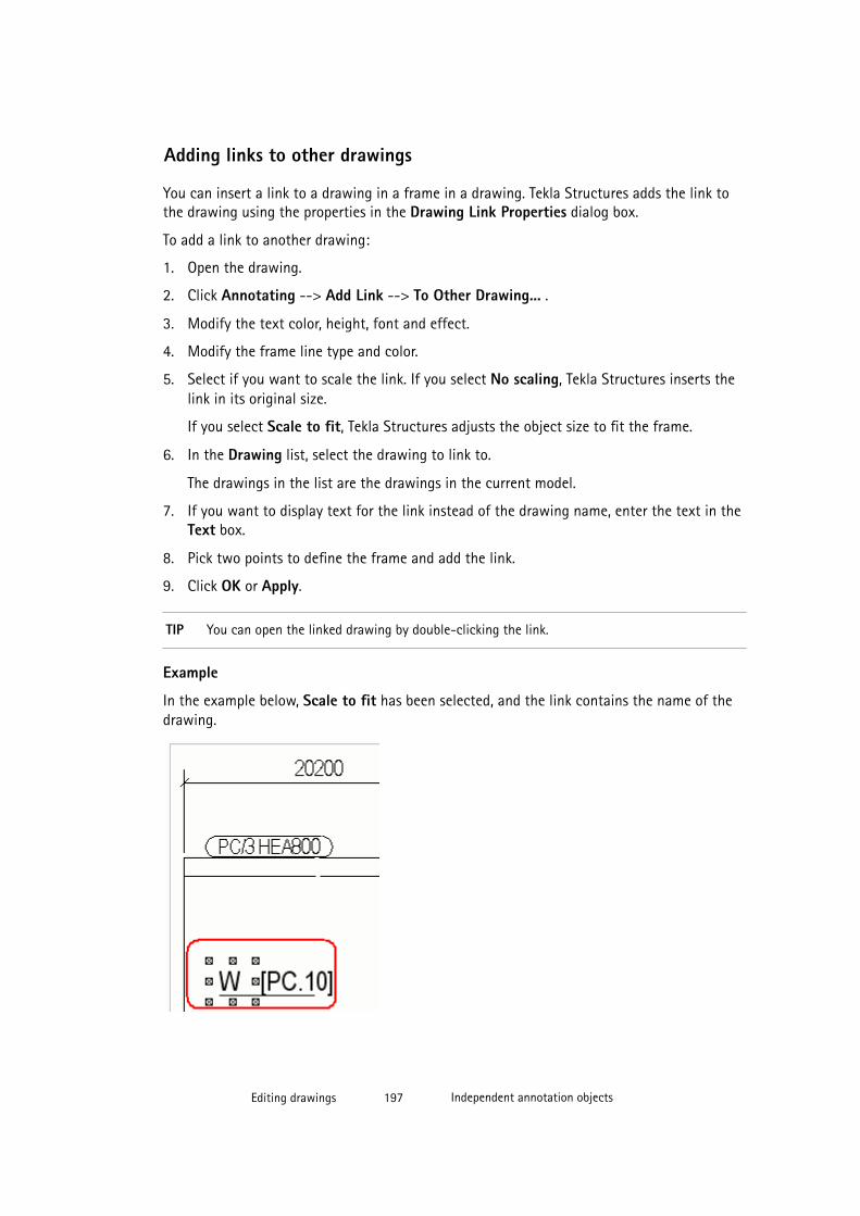
Adding links to other drawings
You can insert a link to a drawing in a frame in a drawing. Tekla Structures adds the link tothe drawing using the properties in the Drawing Link Properties dialog box.
To add a link to another drawing:
1. Open the drawing.
2. Click Annotating --> Add Link --> To Other Drawing... .
3. Modify the text color, height, font and effect.
4. Modify the frame line type and color.
5. Select if you want to scale the link. If you select No scaling, Tekla Structures inserts thelink in its original size.
If you select Scale to fit, Tekla Structures adjusts the object size to fit the frame.
6. In the Drawing list, select the drawing to link to.
The drawings in the list are the drawings in the current model.
7. If you want to display text for the link instead of the drawing name, enter the text in theText box.
8. Pick two points to define the frame and add the link.
9. Click OK or Apply.
TIP You can open the linked drawing by double-clicking the link.
Example
In the example below, Scale to fit has been selected, and the link contains the name of thedrawing.
Editing drawings 197 Independent annotation objects
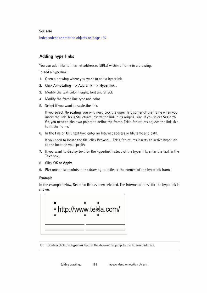
See also
Independent annotation objects on page 192
Adding hyperlinks
You can add links to Internet addresses (URLs) within a frame in a drawing.
To add a hyperlink:
1. Open a drawing where you want to add a hyperlink.
2. Click Annotating --> Add Link --> Hyperlink...
3. Modify the text color, height, font and effect.
4. Modify the frame line type and color.
5. Select if you want to scale the link.
If you select No scaling, you only need pick the upper left corner of the frame when youinsert the link. Tekla Structures inserts the link in its original size. If you select Scale tofit, you need to pick two points to define the frame. Tekla Structures adjusts the link sizeto fit the frame.
6. In the File or URL text box, enter an Internet address or filename and path.
If you need to locate the file, click Browse.... Tekla Structures inserts an active hyperlinkto the location you specify.
7. If you want to display text for the hyperlink instead of the hyperlink, enter the text in theText box.
8. Click OK or Apply.
9. Pick one or two points in the drawing to indicate the corners of the hyperlink frame.
Example
In the example below, Scale to fit has been selected. The Internet address for the hyperlink isshown.
TIP Double-click the hyperlink text in the drawing to jump to the Internet address.
Editing drawings 198 Independent annotation objects

See also
Independent annotation objects on page 192
Adding links to DWG and DXF files
You can insert a DWG or DXF file inside a frame in a drawing. Tekla Structures adds the DWGor DXF file using the properties in the DWG/DXF Properties dialog box. Tekla Structurescreates a link to the selected DWG or DXF file. When you modify the file, Tekla Structuresalso modifies all the links in the drawing.
In DWG/DXF links, Tekla Structures supports Autocad version 2010 and earlier.
To add a link to a DWG or DXF file:
1. Open the drawing where you want to insert a link to a DWG/DXF file.
2. Click View --> Add DWG / DXF File .
3. Select the scaling options:
• Scaling type:
• X: Pick the left upper corner of the frame to insert the file. You can only set thedrawing scale in the x direction.
• XY: Pick the left upper corner of the frame to insert the file. You can set thedrawing scale in both the x and y direction.
• Scale to fit: Pick the left upper and bottom right corners of the frame to size andcreate the frame. Tekla Structures scales the file to fit the frame.
• Best fit: Pick the left upper and bottom right corners of the frame to size andcreate the frame. Tekla Structures scales the file to fit, maintaining its originalaspect ratio.
• Scale in X:
• Scales the file in the x direction. Enter a coefficient to indicate the scale, forexample, 1.0 for 100%, 1.5 for 150%, etc. The scaling type must be set to X orXY.
• Scale in Y:
• Scales the file in the y direction. Enter a coefficient to indicate the scale, forexample, 1.0 for 100%, 1.5 for 150%, etc. The scaling type must be set to XY.
4. Select the link frame line type and color.
5. In Name, browse for the DWG or DXF file you want to use.
6. Pick one or two points in the drawing to place the frame.
7. Click OK or Apply.
Tekla Structures adds the DWG or DXF drawing inside a frame in the drawing.
Editing drawings 199 Independent annotation objects
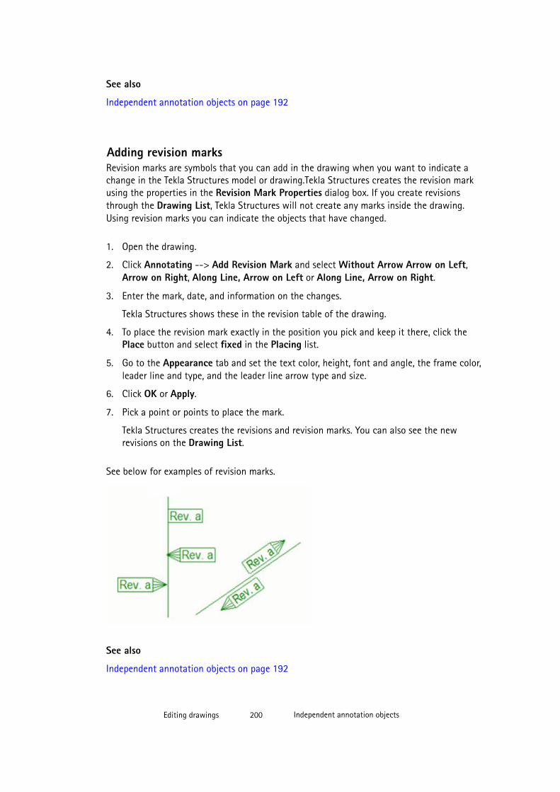
See also
Independent annotation objects on page 192
Adding revision marksRevision marks are symbols that you can add in the drawing when you want to indicate achange in the Tekla Structures model or drawing.Tekla Structures creates the revision markusing the properties in the Revision Mark Properties dialog box. If you create revisionsthrough the Drawing List, Tekla Structures will not create any marks inside the drawing.Using revision marks you can indicate the objects that have changed.
1. Open the drawing.
2. Click Annotating --> Add Revision Mark and select Without Arrow Arrow on Left,Arrow on Right, Along Line, Arrow on Left or Along Line, Arrow on Right.
3. Enter the mark, date, and information on the changes.
Tekla Structures shows these in the revision table of the drawing.
4. To place the revision mark exactly in the position you pick and keep it there, click thePlace button and select fixed in the Placing list.
5. Go to the Appearance tab and set the text color, height, font and angle, the frame color,leader line and type, and the leader line arrow type and size.
6. Click OK or Apply.
7. Pick a point or points to place the mark.
Tekla Structures creates the revisions and revision marks. You can also see the newrevisions on the Drawing List.
See below for examples of revision marks.
See also
Independent annotation objects on page 192
Editing drawings 200 Independent annotation objects

Leader line types on page 576
Revising drawings on page 287
Modifying the properties of independent annotation objects
You can modify the properties of texts, symbols, links, hyperlinks, links to DWG and DXF files,and revision marks in an open drawing.
To modify the properties of the independent annotation objects:
1. Double-click the object.
2. Switch all the check boxes off in the dialog box by clicking the on/off switch at the bottom of the dialog box.
3. Select only the check boxes next to the properties that you want to modify.
4. Modify the properties.
5. Click Modify.
See also
Independent annotation objects on page 192
4.7 Drawing shapes
Drawing shapes are objects that you add in a drawing mostly to highlight informationexisting in the Tekla Structures model.
In Tekla Structures drawings, the additional drawing objects can be clouds, lines, circles,rectangles, arcs, polylines, polygons and cover-up areas and cover-up lines.
Drawing shapes are associative if the have associativity points, i.e. they are associated to abuilding object.
See also
Drawing objects on page 17
Creating a shape in a drawing on page 201
Hiding building object outlines using cover-up tools on page 205
Drawing shape properties on page 613
Hiding building object outlines using cover-up tools on page 205
Editing drawings 201 Drawing shapes
Creating a shape in a drawing
You can create lines, rectangles, circles, arcs, polygons, polylines, clouds and cover-up areasand lines in an open drawing.
To create a shape:
1. Hold down Shift, click Shapes and select one of the commands.
• Draw Line: Draw a line between two points you pick.
• Draw Rectangle: Draw a rectangle between points you pick. You can createrectangles with horizontal and vertical sides. To rotate the rectangle, use Edit >Move > Rotate.
• Draw Circle > By Center and Radius: Draw a circle by picking the center point firstand then a point on the circle that specifies the radius.
• Draw Circle > By Three Points: Draw a circle that traverses the three points youpick, either clockwise or counter-clockwise.
• Draw Arc > By Endpoints and Center: Draw an arc by specifying two end pointsfirst and then a center point. The center point specifies the center of the circle ofwhich the arc is a part.
• Draw Arc > By Three Points: Draw an arc that traverses the three points you pick,either clockwise or counter-clockwise.
• Draw Polyline: Draw a line with straight or curved segments. Bulge factor for alllines is useful when you are creating curved polylines.
• Draw Polygon: Draw a polygon by picking the corner points. To close the polygon,pick the starting corner point again or click the middle mouse button. Use thiscommand to create closed polylines, which you cannot with Draw Polyline.
• Draw Cloud: Create a cloud that traverses the points you pick. Close the cloud byclicking the middle mouse button. Set the Bulge factor for all lines for clouds in theproperties dialog box.
• Draw Cover-up Area: Quickly hide model object outlines in drawings. To use, selectthe command and draw a non-transparent rectangular area over the model objectoutline that you want to hide.
• Draw Cover-up Line: Quickly hide model object outlines in drawings. To use, selectthe command and draw a non-transparent line over the model object outline thatyou want to hide.
2. Modify the properties as required.
3. Click OK or Apply.
4. Create the drawing shape by following the instructions on the status bar.
See also
Drawing shapes on page 201
Drawing shape properties on page 613
Editing drawings 202 Drawing shapes
Defining customized line types on page 542
Hiding building object outlines using cover-up tools on page 205
4.8 Building objects in drawings
Building objects are 2D representations of the 3D parts that you have created in the model.After making the drawing, you can change the appearance and representation of the buildingobjects in an open drawing.
NOTE If you want to change the model weld properties, go back to the model, and makethe changes there. In the drawing, you can only change visibility settings andappearance of the model welds. For manually added drawing weld marks theproperties can be changed in the drawings.
See also
Editing drawings on page 117
Modifying building objects on page 203
Shortening parts view by view on page 204
Hiding building object outlines using cover-up tools on page 205
Edge chamfers in drawings on page 228
Showing a single reinforcing bar in a group on page 206
Part and neighbor part properties in drawings on page 592
Showing layer information on reinforcing bars in drawings (RebarLayeringMarker) on page207
Drawing objects on page 17
Modifying building objects
You can modify the drawing properties of the building objects (parts, bolts, reinforcement,surface treatment) in an open drawing.
Limitations: The color of the center lines can be changed only on the drawing and view level,not on the object level. For center lines, you can adjust only the color in the properties dialogbox, not the type. You can adjust the line type of part center lines with the advanced option XS_CENTER_LINE_TYPE.
To modify the properties of a building object in a drawing:
1. Double-click a building object, for example a part, reinforcement, surface treatment, orbolt.
Editing drawings 203 Building objects in drawings
2. Switch all the check boxes off in the dialog box by clicking the on/off switch at the bottom of the dialog box.
3. Select the check boxes of only those properties that you want to modify.
4. On the Contents tab, select the part representation, whether to show hidden lines, centerlines and reference lines, and which additional markings to show.
5. On the Appearance tab, select the color and type of the lines.
It is easier to adjust the center line color, if you hide the hidden lines on the Contentstab first.
6. On the Fill tab, set the part and section fill options.
7. Click Modify.
See also
Part and neighbor part properties in drawings on page 592
Bolt content and appearance properties in drawings on page 595
Surface treatment visibility and content properties in drawings on page 596
Reinforcement/Neighbor reinforcement and mesh properties in drawings on page 601
XS_DRAWING_PART_REFERENCE_LINE_TYPE
XS_CENTER_LINE_TYPE
XS_DRAWING_POINT_SCALE
Example: Part representations on page 513
Adding automatic hatch patterns on drawing objects on page 526
Shortening parts view by view
You can shorten parts in the selected view in an open drawing.
To shorten parts view by view:
1. Double-click the view frame.
2. In the View Properties dialog box, go to the Attributes2 tab.
3. In Cut parts, select Yes, Only in x direction or Only in y direction.
4. In Cut skew parts, select if you want to cut skewed parts.
5. In Minimum cut part length, set the minimum length of the shortened part.
This option defines how long the part must at least be to get shortened. The length of thepart must be at least twice the entered value.
6. In Space between cut parts, enter the distance between the cut parts on paper.
7. Click Modify.
Editing drawings 204 Building objects in drawings
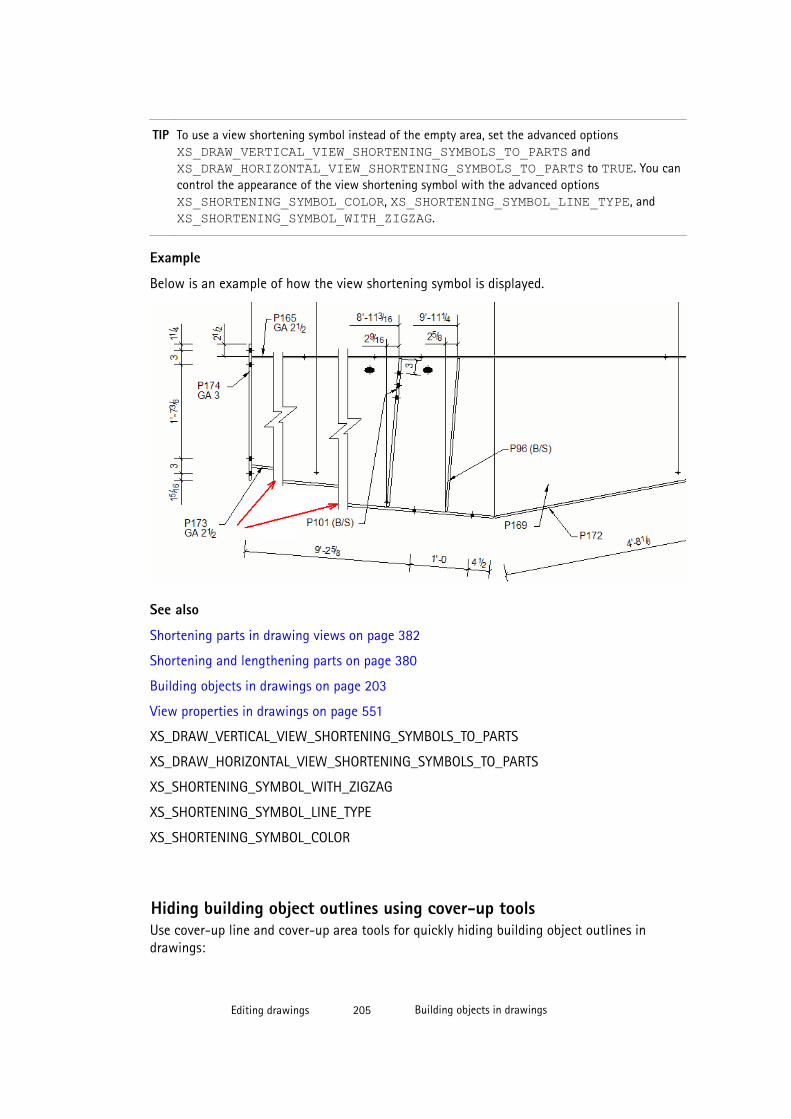
TIP To use a view shortening symbol instead of the empty area, set the advanced options XS_DRAW_VERTICAL_VIEW_SHORTENING_SYMBOLS_TO_PARTS and XS_DRAW_HORIZONTAL_VIEW_SHORTENING_SYMBOLS_TO_PARTS to TRUE. You cancontrol the appearance of the view shortening symbol with the advanced options XS_SHORTENING_SYMBOL_COLOR, XS_SHORTENING_SYMBOL_LINE_TYPE, and XS_SHORTENING_SYMBOL_WITH_ZIGZAG.
Example
Below is an example of how the view shortening symbol is displayed.
See also
Shortening parts in drawing views on page 382
Shortening and lengthening parts on page 380
Building objects in drawings on page 203
View properties in drawings on page 551
XS_DRAW_VERTICAL_VIEW_SHORTENING_SYMBOLS_TO_PARTS
XS_DRAW_HORIZONTAL_VIEW_SHORTENING_SYMBOLS_TO_PARTS
XS_SHORTENING_SYMBOL_WITH_ZIGZAG
XS_SHORTENING_SYMBOL_LINE_TYPE
XS_SHORTENING_SYMBOL_COLOR
Hiding building object outlines using cover-up toolsUse cover-up line and cover-up area tools for quickly hiding building object outlines indrawings:
Editing drawings 205 Building objects in drawings
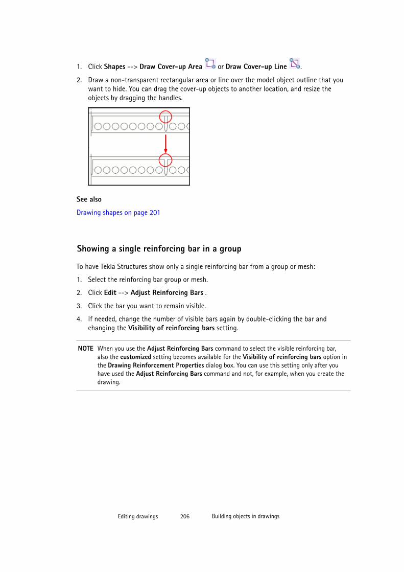
1. Click Shapes --> Draw Cover-up Area or Draw Cover-up Line .
2. Draw a non-transparent rectangular area or line over the model object outline that youwant to hide. You can drag the cover-up objects to another location, and resize theobjects by dragging the handles.
See also
Drawing shapes on page 201
Showing a single reinforcing bar in a group
To have Tekla Structures show only a single reinforcing bar from a group or mesh:
1. Select the reinforcing bar group or mesh.
2. Click Edit --> Adjust Reinforcing Bars .
3. Click the bar you want to remain visible.
4. If needed, change the number of visible bars again by double-clicking the bar andchanging the Visibility of reinforcing bars setting.
NOTE When you use the Adjust Reinforcing Bars command to select the visible reinforcing bar,also the customized setting becomes available for the Visibility of reinforcing bars option inthe Drawing Reinforcement Properties dialog box. You can use this setting only after youhave used the Adjust Reinforcing Bars command and not, for example, when you create thedrawing.
Editing drawings 206 Building objects in drawings
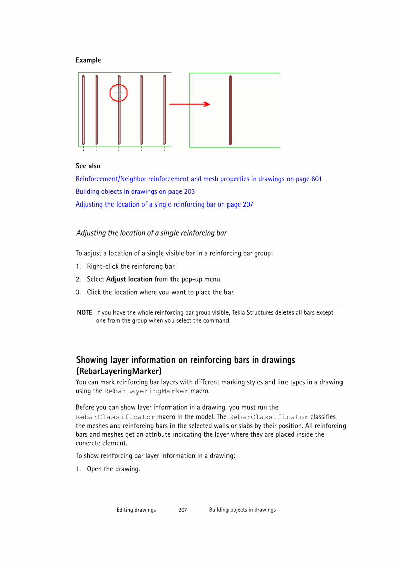
Example
See also
Reinforcement/Neighbor reinforcement and mesh properties in drawings on page 601
Building objects in drawings on page 203
Adjusting the location of a single reinforcing bar on page 207
Adjusting the location of a single reinforcing bar
To adjust a location of a single visible bar in a reinforcing bar group:
1. Right-click the reinforcing bar.
2. Select Adjust location from the pop-up menu.
3. Click the location where you want to place the bar.
NOTE If you have the whole reinforcing bar group visible, Tekla Structures deletes all bars exceptone from the group when you select the command.
Showing layer information on reinforcing bars in drawings(RebarLayeringMarker)You can mark reinforcing bar layers with different marking styles and line types in a drawingusing the RebarLayeringMarker macro.
Before you can show layer information in a drawing, you must run the RebarClassificator macro in the model. The RebarClassificator classifiesthe meshes and reinforcing bars in the selected walls or slabs by their position. All reinforcingbars and meshes get an attribute indicating the layer where they are placed inside theconcrete element.
To show reinforcing bar layer information in a drawing:
1. Open the drawing.
Editing drawings 207 Building objects in drawings

2. Click the Applications and Components button in the upper-right corner of theTekla Structures main window to open the Applications and Components catalog.
3. Click the arrow next to Applications to open the applications list.
4. Double-click RebarLayeringMarker to display the Rebar Layering marker dialogbox.
5. On the Marking style tab, select the marking style you want to use (symbol style or levelprefix style).
6. On the Marking settings tab, select the marker line type.
7. On the Marking settings tab, do one of the following depending on the selected markingstyle:
• For symbol style markers, select the symbol you want to use, and the symbol height.
• For level prefix style markers, select the level prefix.
8. Click All objects to show layering markers on all reinforcing bars, or select the individualreinforcing bars and click Selected objects to show the markers on the selected barsonly.
1. Level prefix style layering marker. The number, for example number 1 in T1, indicates thelayer number. The letter, for example T in T1, indicates whether the reinforcing bar is onthe top, bottom, near side or far side layer.
2. Symbol style layering marker. The number of triangles indicates the layer number fromthe face. Triangle orientation indicates whether the reinforcing bar is on the top, bottom,near side or far side layer. For example for top bars, the triangle head points downwards,and for bottom bars upwards.
Editing drawings 208 Custom presentations in drawings
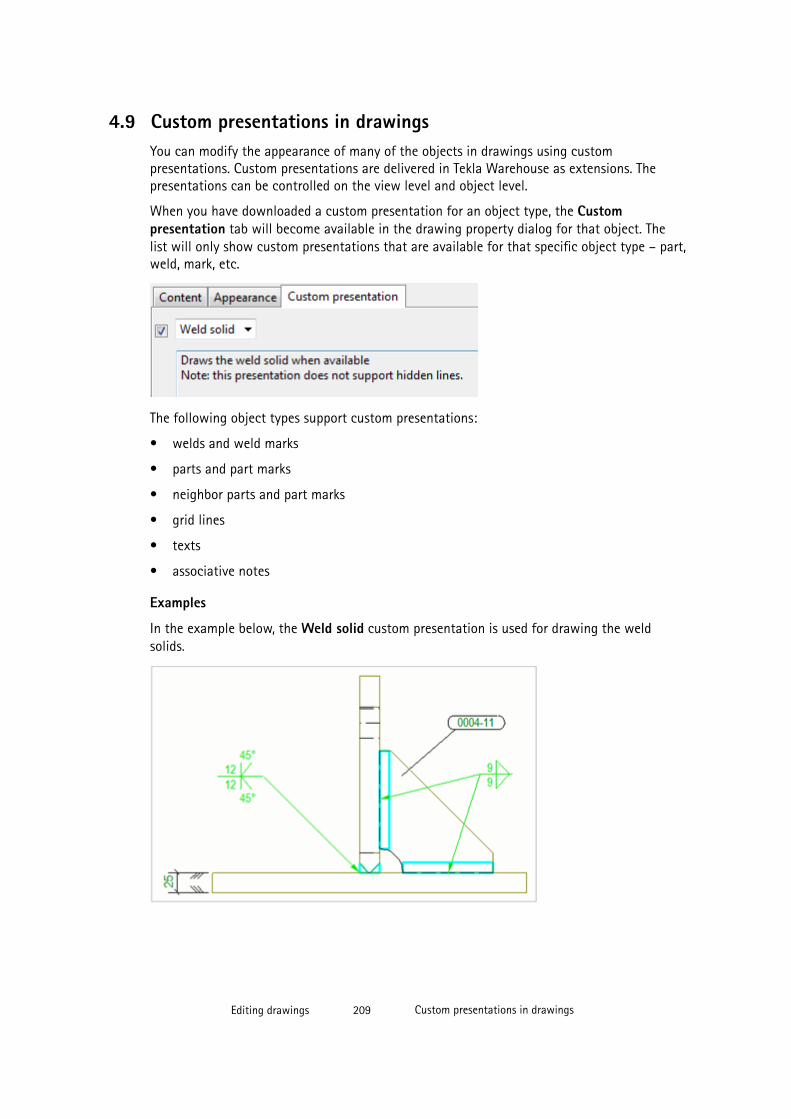
4.9 Custom presentations in drawingsYou can modify the appearance of many of the objects in drawings using custompresentations. Custom presentations are delivered in Tekla Warehouse as extensions. Thepresentations can be controlled on the view level and object level.
When you have downloaded a custom presentation for an object type, the Custompresentation tab will become available in the drawing property dialog for that object. Thelist will only show custom presentations that are available for that specific object type – part,weld, mark, etc.
The following object types support custom presentations:
• welds and weld marks
• parts and part marks
• neighbor parts and part marks
• grid lines
• texts
• associative notes
Examples
In the example below, the Weld solid custom presentation is used for drawing the weldsolids.
Editing drawings 209 Custom presentations in drawings
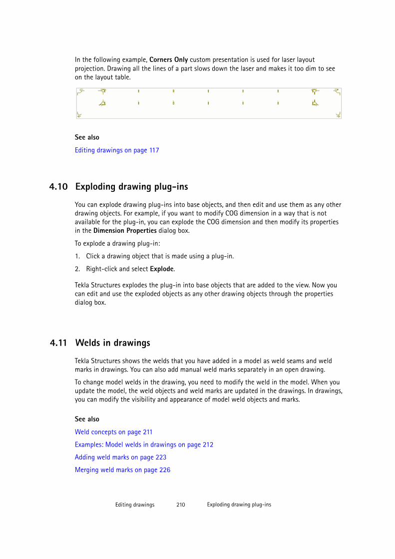
In the following example, Corners Only custom presentation is used for laser layoutprojection. Drawing all the lines of a part slows down the laser and makes it too dim to seeon the layout table.
See also
Editing drawings on page 117
4.10 Exploding drawing plug-ins
You can explode drawing plug-ins into base objects, and then edit and use them as any otherdrawing objects. For example, if you want to modify COG dimension in a way that is notavailable for the plug-in, you can explode the COG dimension and then modify its propertiesin the Dimension Properties dialog box.
To explode a drawing plug-in:
1. Click a drawing object that is made using a plug-in.
2. Right-click and select Explode.
Tekla Structures explodes the plug-in into base objects that are added to the view. Now youcan edit and use the exploded objects as any other drawing objects through the propertiesdialog box.
4.11 Welds in drawings
Tekla Structures shows the welds that you have added in a model as weld seams and weldmarks in drawings. You can also add manual weld marks separately in an open drawing.
To change model welds in the drawing, you need to modify the weld in the model. When youupdate the model, the weld objects and weld marks are updated in the drawings. In drawings,you can modify the visibility and appearance of model weld objects and marks.
See also
Weld concepts on page 211
Examples: Model welds in drawings on page 212
Adding weld marks on page 223
Merging weld marks on page 226
Editing drawings 210 Exploding drawing plug-ins
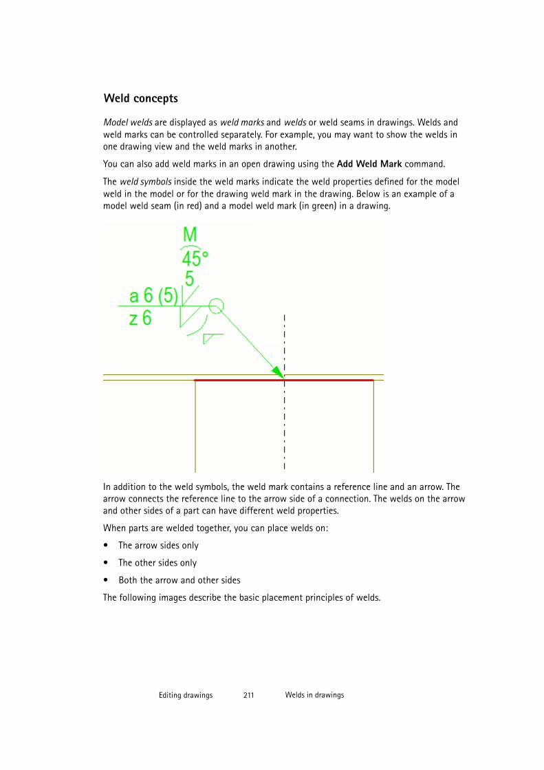
Weld concepts
Model welds are displayed as weld marks and welds or weld seams in drawings. Welds andweld marks can be controlled separately. For example, you may want to show the welds inone drawing view and the weld marks in another.
You can also add weld marks in an open drawing using the Add Weld Mark command.
The weld symbols inside the weld marks indicate the weld properties defined for the modelweld in the model or for the drawing weld mark in the drawing. Below is an example of amodel weld seam (in red) and a model weld mark (in green) in a drawing.
In addition to the weld symbols, the weld mark contains a reference line and an arrow. Thearrow connects the reference line to the arrow side of a connection. The welds on the arrowand other sides of a part can have different weld properties.
When parts are welded together, you can place welds on:
• The arrow sides only
• The other sides only
• Both the arrow and other sides
The following images describe the basic placement principles of welds.
Editing drawings 211 Welds in drawings
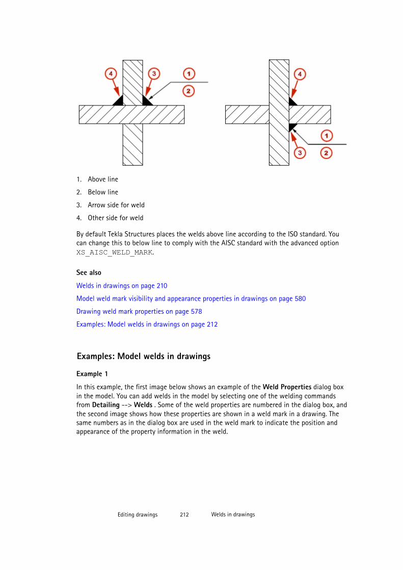
1. Above line
2. Below line
3. Arrow side for weld
4. Other side for weld
By default Tekla Structures places the welds above line according to the ISO standard. Youcan change this to below line to comply with the AISC standard with the advanced option XS_AISC_WELD_MARK.
See also
Welds in drawings on page 210
Model weld mark visibility and appearance properties in drawings on page 580
Drawing weld mark properties on page 578
Examples: Model welds in drawings on page 212
Examples: Model welds in drawings
Example 1
In this example, the first image below shows an example of the Weld Properties dialog boxin the model. You can add welds in the model by selecting one of the welding commandsfrom Detailing --> Welds . Some of the weld properties are numbered in the dialog box, andthe second image shows how these properties are shown in a weld mark in a drawing. Thesame numbers as in the dialog box are used in the weld mark to indicate the position andappearance of the property information in the weld.
Editing drawings 212 Welds in drawings
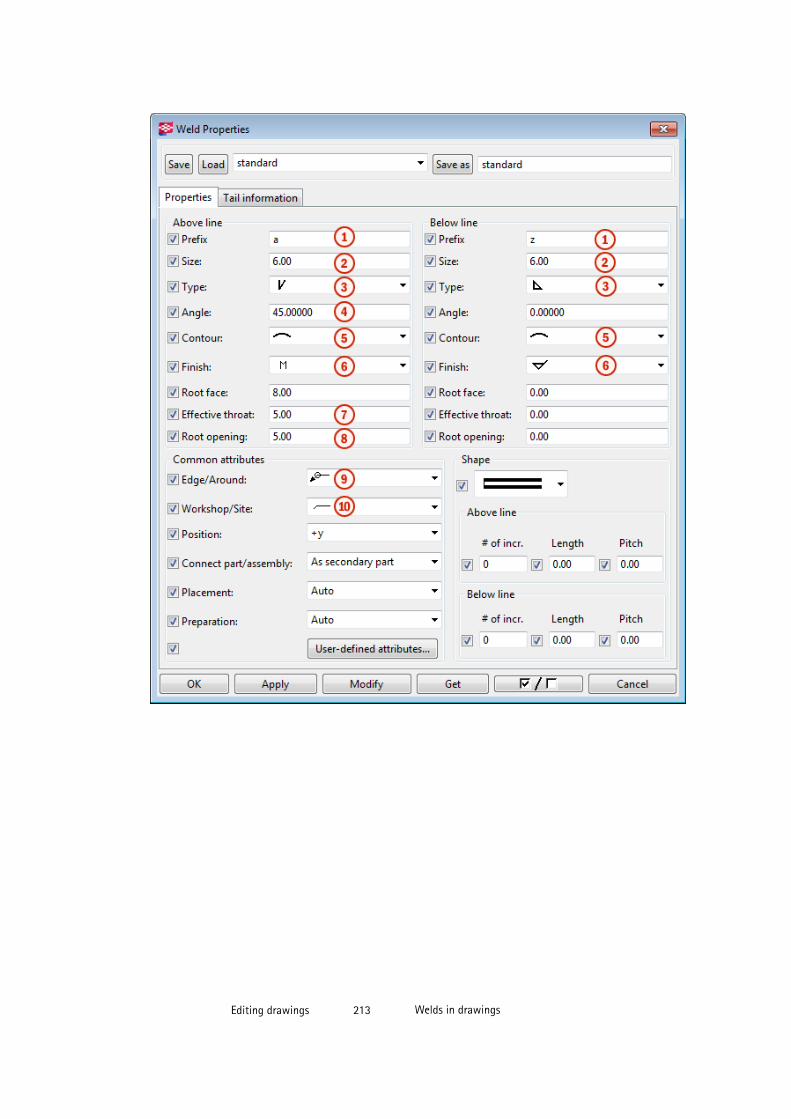
Editing drawings 213 Welds in drawings

1. Weld prefix
2. Weld size
3. Weld type
4. Weld angle
5. Weld contour symbol
6. Weld finishing symbol
7. Effective throat
8. Root opening
9. Edge/Around, weld around symbol is used
10. Workshop/Site, site weld symbol is used
Example 2
The example below shows a staggered, intermittent weld. The length is set to 50 and thepitch to 100.
Editing drawings 214 Welds in drawings

1. Staggered, intermittent weld
2. Length of weld segment
3. Pitch (center-to-center spacing) of weld segments
Example 3
The example below shows a non-staggered, intermittent weld. The length is set to 50 and thepitch to 100. The pitch is shown in the weld mark, if the pitch value is greater than 0.0.
Editing drawings 215 Welds in drawings
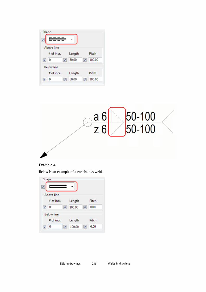
Example 4
Below is an example of a continuous weld.
Editing drawings 216 Welds in drawings
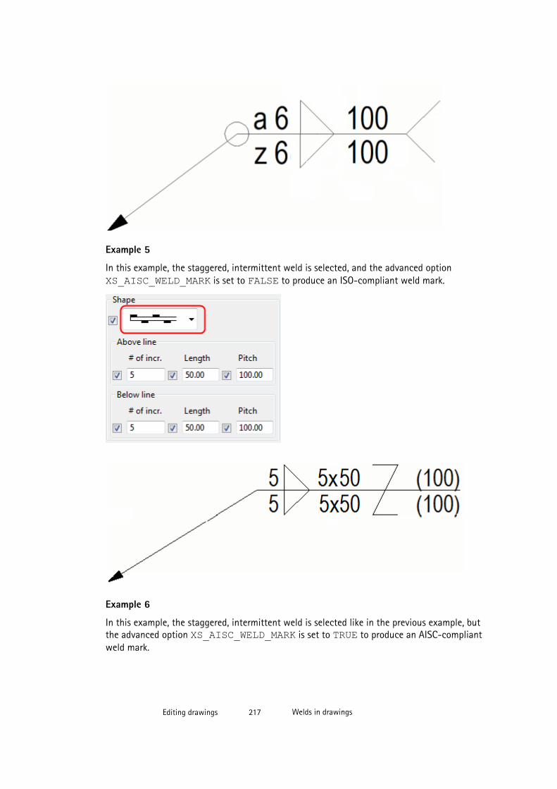
Example 5
In this example, the staggered, intermittent weld is selected, and the advanced option XS_AISC_WELD_MARK is set to FALSE to produce an ISO-compliant weld mark.
Example 6
In this example, the staggered, intermittent weld is selected like in the previous example, butthe advanced option XS_AISC_WELD_MARK is set to TRUE to produce an AISC-compliantweld mark.
Editing drawings 217 Welds in drawings
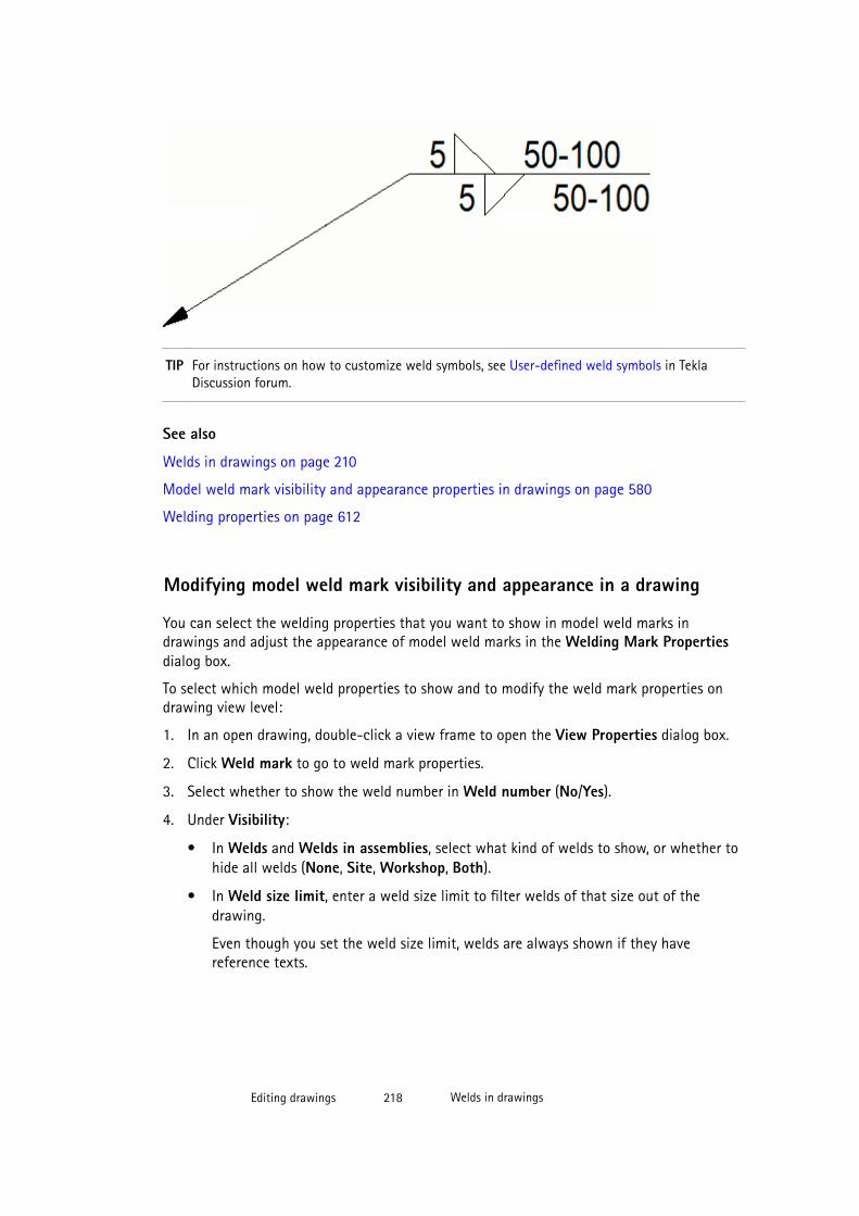
TIP For instructions on how to customize weld symbols, see User-defined weld symbols in TeklaDiscussion forum.
See also
Welds in drawings on page 210
Model weld mark visibility and appearance properties in drawings on page 580
Welding properties on page 612
Modifying model weld mark visibility and appearance in a drawing
You can select the welding properties that you want to show in model weld marks indrawings and adjust the appearance of model weld marks in the Welding Mark Propertiesdialog box.
To select which model weld properties to show and to modify the weld mark properties ondrawing view level:
1. In an open drawing, double-click a view frame to open the View Properties dialog box.
2. Click Weld mark to go to weld mark properties.
3. Select whether to show the weld number in Weld number (No/Yes).
4. Under Visibility:
• In Welds and Welds in assemblies, select what kind of welds to show, or whether tohide all welds (None, Site, Workshop, Both).
• In Weld size limit, enter a weld size limit to filter welds of that size out of thedrawing.
Even though you set the weld size limit, welds are always shown if they havereference texts.
Editing drawings 218 Welds in drawings
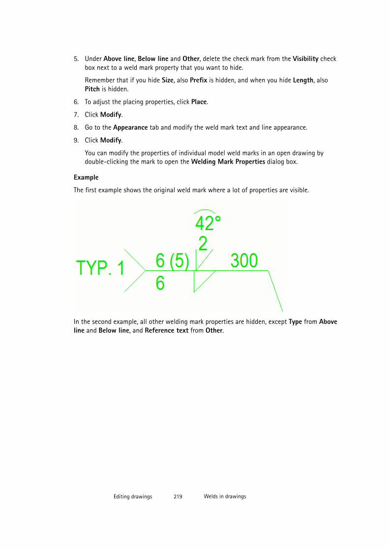
5. Under Above line, Below line and Other, delete the check mark from the Visibility checkbox next to a weld mark property that you want to hide.
Remember that if you hide Size, also Prefix is hidden, and when you hide Length, alsoPitch is hidden.
6. To adjust the placing properties, click Place.
7. Click Modify.
8. Go to the Appearance tab and modify the weld mark text and line appearance.
9. Click Modify.
You can modify the properties of individual model weld marks in an open drawing bydouble-clicking the mark to open the Welding Mark Properties dialog box.
Example
The first example shows the original weld mark where a lot of properties are visible.
In the second example, all other welding mark properties are hidden, except Type from Aboveline and Below line, and Reference text from Other.
Editing drawings 219 Welds in drawings
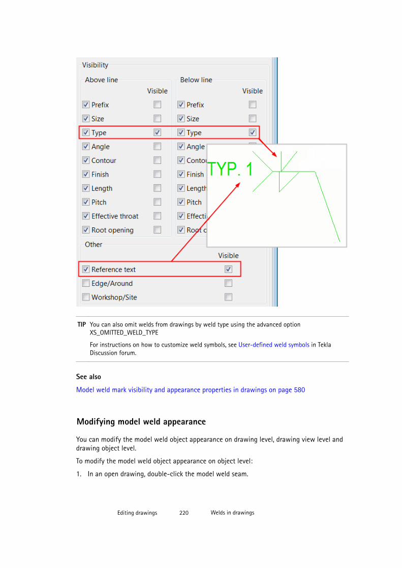
TIP You can also omit welds from drawings by weld type using the advanced optionXS_OMITTED_WELD_TYPE
For instructions on how to customize weld symbols, see User-defined weld symbols in TeklaDiscussion forum.
See also
Model weld mark visibility and appearance properties in drawings on page 580
Modifying model weld appearance
You can modify the model weld object appearance on drawing level, drawing view level anddrawing object level.
To modify the model weld object appearance on object level:
1. In an open drawing, double-click the model weld seam.
Editing drawings 220 Welds in drawings

It is easier to select the model weld, if you have only the Select drawing welds selection
switch selected.
2. Modify the color of the weld.
3. Modify the weld line type.
4. Click Modify.
TIP You can modify the properties of model weld objects on view level by double-clicking frame ofthe drawing view containing the weld objects and selecting Welds.
See also
Welding properties on page 612
Welds in drawings on page 210
Dragging weld marks
You can drag the model welds by the base point of the weld mark leader line along the weldseam. This way you can position the weld marks more optimally for increased clarity in thedrawings.
TIP Turn on Smart Select ( Tools --> Options --> Smart Select ), this makes selecting theleader line base point much easier.
To drag model weld marks:
1. Click the weld mark near the leader line base point.
2. Hold down the left mouse button and drag the base point to a new location by the leaderline base point handle located in the tip of the arrow.
Limitations
You cannot drag the leader base point to the back-side of a double-sided weld.
Editing drawings 221 Welds in drawings
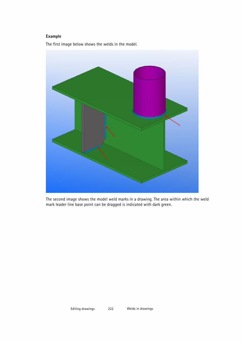
Example
The first image below shows the welds in the model.
The second image shows the model weld marks in a drawing. The area within which the weldmark leader line base point can be dragged is indicated with dark green.
Editing drawings 222 Welds in drawings

See also
Welds in drawings on page 210
Adding weld marks
A weld mark is an associative annotation object that contains a set of weld properties. Youcan define automatic weld marks when you create the drawing, and also add additional weldmarks in the drawing. Tekla Structures creates manual weld marks using the properties in theWeld Mark Properties dialog box.
To add weld marks:
1. Hold down Shift and click Annotating --> Add Weld Mark to open the Weld MarkProperties dialog box.
Editing drawings 223 Welds in drawings
2. Enter or modify the content and the appearance of the weld mark.
To exactly place the weld mark in the position you pick and keep it there, click thePlace... button and select fixed in the Placing list.
3. Click Apply or OK to save the properties.
4. Pick a position for the weld mark.
You can drag the drawing weld mark freely to a more suitable location by the leader basepoint handle.
See also
Welds in drawings on page 210
Drawing weld mark properties on page 578
Defining placement settings for annotation objects on page 362
Example: Weld marks added in drawings
In this example, the first image below is the Weld Mark Properties dialog box in a drawing.The weld mark properties are numbered in the dialog box. The second image shows how theweld mark properties are displayed in a weld mark in a drawing. The same numbers are used
Editing drawings 224 Welds in drawings
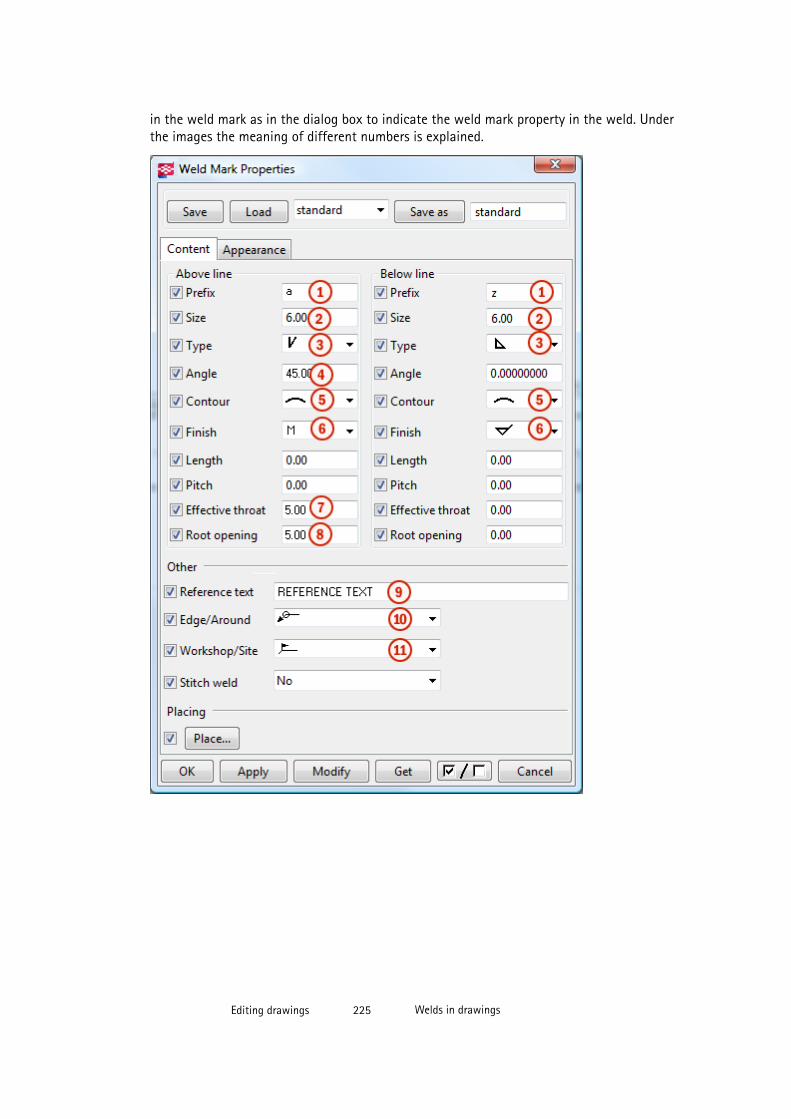
in the weld mark as in the dialog box to indicate the weld mark property in the weld. Underthe images the meaning of different numbers is explained.
Editing drawings 225 Welds in drawings
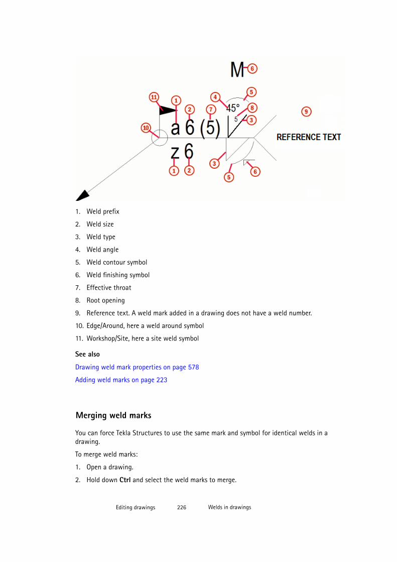
1. Weld prefix
2. Weld size
3. Weld type
4. Weld angle
5. Weld contour symbol
6. Weld finishing symbol
7. Effective throat
8. Root opening
9. Reference text. A weld mark added in a drawing does not have a weld number.
10. Edge/Around, here a weld around symbol
11. Workshop/Site, here a site weld symbol
See also
Drawing weld mark properties on page 578
Adding weld marks on page 223
Merging weld marks
You can force Tekla Structures to use the same mark and symbol for identical welds in adrawing.
To merge weld marks:
1. Open a drawing.
2. Hold down Ctrl and select the weld marks to merge.
Editing drawings 226 Welds in drawings

3. Right-click and select Merge from the pop-up menu.
Tekla Structures combines the marks.
4. If needed, you can split merged weld marks by right-clicking the mark and selecting Splitfrom the pop-up menu.
Description Example
Original drawing
Merged weld marks.
Editing drawings 227 Welds in drawings
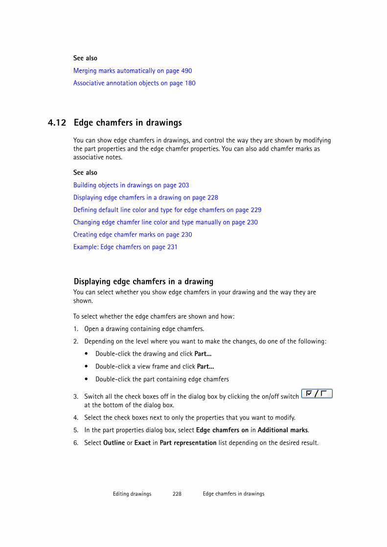
See also
Merging marks automatically on page 490
Associative annotation objects on page 180
4.12 Edge chamfers in drawings
You can show edge chamfers in drawings, and control the way they are shown by modifyingthe part properties and the edge chamfer properties. You can also add chamfer marks asassociative notes.
See also
Building objects in drawings on page 203
Displaying edge chamfers in a drawing on page 228
Defining default line color and type for edge chamfers on page 229
Changing edge chamfer line color and type manually on page 230
Creating edge chamfer marks on page 230
Example: Edge chamfers on page 231
Displaying edge chamfers in a drawingYou can select whether you show edge chamfers in your drawing and the way they areshown.
To select whether the edge chamfers are shown and how:
1. Open a drawing containing edge chamfers.
2. Depending on the level where you want to make the changes, do one of the following:
• Double-click the drawing and click Part...
• Double-click a view frame and click Part...
• Double-click the part containing edge chamfers
3. Switch all the check boxes off in the dialog box by clicking the on/off switch at the bottom of the dialog box.
4. Select the check boxes next to only the properties that you want to modify.
5. In the part properties dialog box, select Edge chamfers on in Additional marks.
6. Select Outline or Exact in Part representation list depending on the desired result.
Editing drawings 228 Edge chamfers in drawings
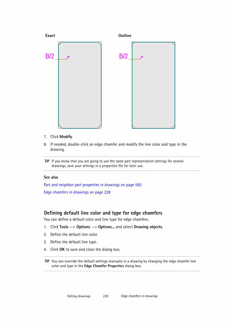
Exact Outline
7. Click Modify.
8. If needed, double-click an edge chamfer and modify the line color and type in thedrawing.
TIP If you know that you are going to use the same part representation settings for severaldrawings, save your settings in a properties file for later use.
See also
Part and neighbor part properties in drawings on page 592
Edge chamfers in drawings on page 228
Defining default line color and type for edge chamfersYou can define a default color and line type for edge chamfers.
1. Click Tools --> Options --> Options... and select Drawing objects.
2. Define the default line color.
3. Define the default line type.
4. Click OK to save and close the dialog box.
TIP You can override the default settings manually in a drawing by changing the edge chamfer linecolor and type in the Edge Chamfer Properties dialog box.
Editing drawings 229 Edge chamfers in drawings
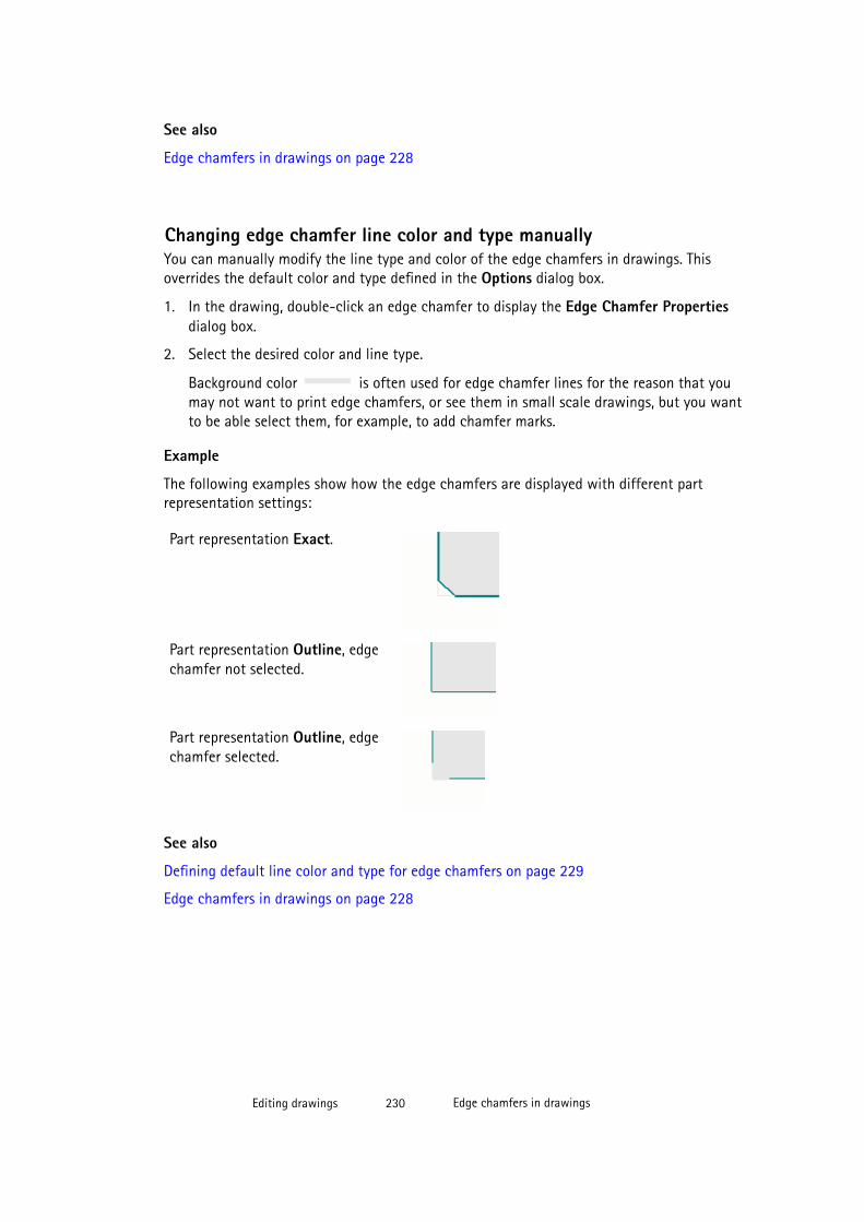
See also
Edge chamfers in drawings on page 228
Changing edge chamfer line color and type manuallyYou can manually modify the line type and color of the edge chamfers in drawings. Thisoverrides the default color and type defined in the Options dialog box.
1. In the drawing, double-click an edge chamfer to display the Edge Chamfer Propertiesdialog box.
2. Select the desired color and line type.
Background color is often used for edge chamfer lines for the reason that youmay not want to print edge chamfers, or see them in small scale drawings, but you wantto be able select them, for example, to add chamfer marks.
Example
The following examples show how the edge chamfers are displayed with different partrepresentation settings:
Part representation Exact.
Part representation Outline, edgechamfer not selected.
Part representation Outline, edgechamfer selected.
See also
Defining default line color and type for edge chamfers on page 229
Edge chamfers in drawings on page 228
Editing drawings 230 Edge chamfers in drawings

Creating edge chamfer marksYou can add associative notes to edge chamfers and use them as part marks.
To add a chamfer mark:
1. Modify the part properties and edge chamfer properties so that edge chamfers are visibleand you can easily select them.
2. Hold down Shift and click Annotating --> Add Associative Note and select the type ofnote you want to create.
3. In the Associative Note Properties dialog box, modify the note properties as required.
4. Select Edge chamfer from the Content list.
5. Add the elements that you want to have in the edge chamfer mark.
6. Click the edge chamfer.
If you use a leader line, you need to pick a position for the note.
See also
Edge chamfers in drawings on page 228
Adding associative notes on page 183
Example: Edge chamfers
See below for typical examples of the ways showing edge chamfers.
In this example, Part representation is Exact and Edge chamfers are on. Background coloris used in edge chamfer lines, because you usually do not want to show edge chamfers inprintouts, but may want to see and select them in the drawing, for example, to addassociative notes.
Editing drawings 231 Edge chamfers in drawings
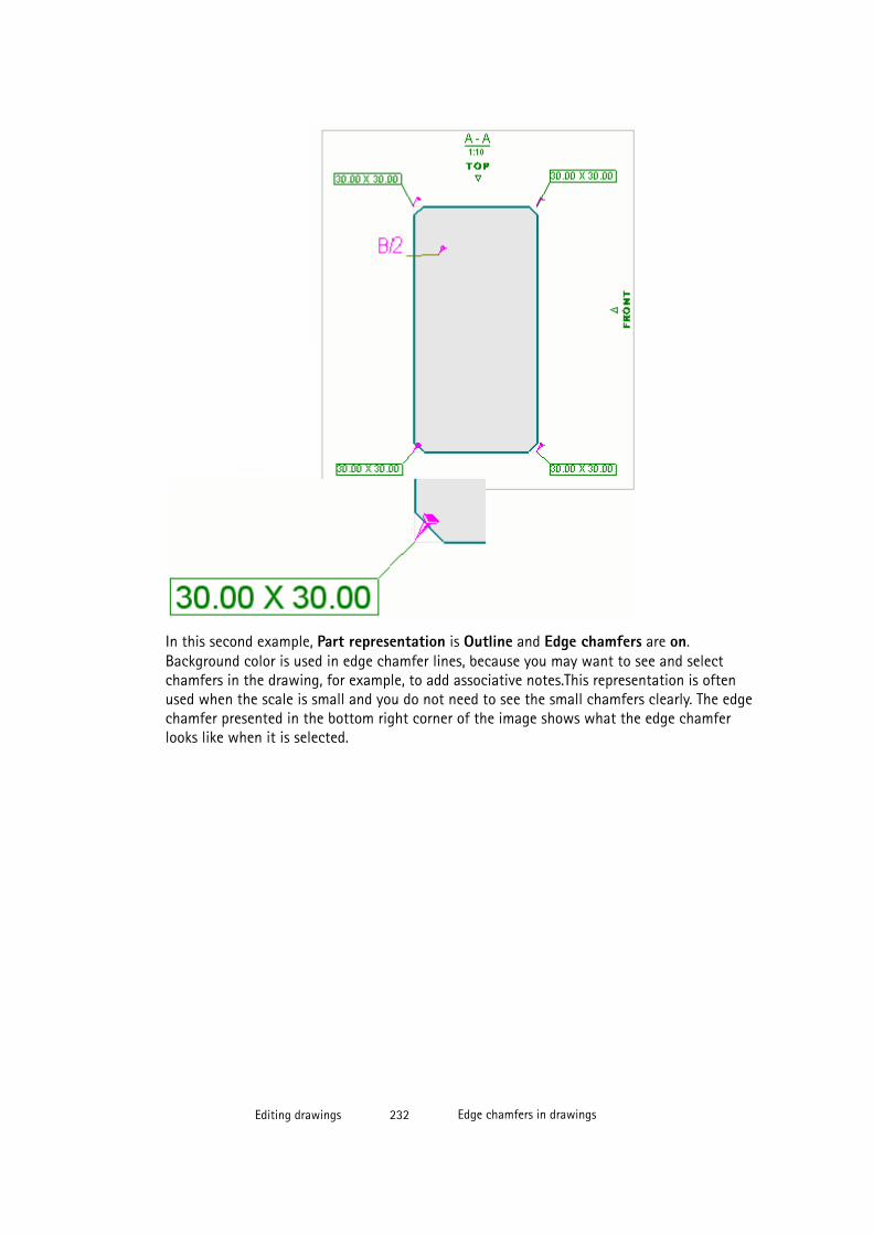
In this second example, Part representation is Outline and Edge chamfers are on.Background color is used in edge chamfer lines, because you may want to see and selectchamfers in the drawing, for example, to add associative notes.This representation is oftenused when the scale is small and you do not need to see the small chamfers clearly. The edgechamfer presented in the bottom right corner of the image shows what the edge chamferlooks like when it is selected.
Editing drawings 232 Edge chamfers in drawings
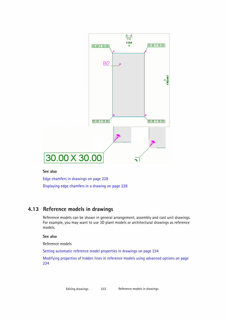
See also
Edge chamfers in drawings on page 228
Displaying edge chamfers in a drawing on page 228
4.13 Reference models in drawingsReference models can be shown in general arrangement, assembly and cast unit drawings.For example, you may want to use 3D plant models or architectural drawings as referencemodels.
See also
Reference models
Setting automatic reference model properties in drawings on page 234
Modifying properties of hidden lines in reference models using advanced options on page234
Editing drawings 233 Reference models in drawings
Setting automatic reference model properties in drawings
To show or hide reference models in cast unit, assembly or general arrangement drawings,and change their visibility setting before creating a drawing:
1. Click Drawings & Reports --> Drawing Settings and select the drawing type.
2. Load the properties that you want to change.
3. Cast unit and assembly drawings: Click View creation, select the view and the propertiesthat you want to change, and click View properties.
4. Click Reference objects.
The Content tab lists all the reference models included in the model.
5. In the Visibility column, select Visible from the list to show the selected referencemodels in the drawing.
6. Go to the Appearance tab and select the line color and type for all visible referencemodels.
7. Cast unit and assembly drawings: Click Save to save the view properties.
8. Click OK.
9. Click Save to save the drawing properties, then click OK and create the drawing.
TIP You can control the visibility and line type of hidden lines in reference models in drawings usingadvanced options XS_SHOW_REFERENCE_MODEL_HIDDEN_LINES, XS_REFERENCE_MODEL_LINES_HIDDEN_BY_ITSELF, XS_REFERENCE_MODEL_LINES_HIDDEN_BY_OTHER_REFERENCE_MODELS, XS_REFERENCE_MODEL_LINES_HIDDEN_BY_PARTS, XS_REFERENCE_MODELS_HIDE_PART_LINES, and XS_REFERENCE_MODEL_HIDDEN_LINE_TYPE.
See also
Modifying properties of hidden lines in reference models using advanced options on page234
Reference models in drawings on page 233
Modifying properties of hidden lines in reference models usingadvanced options
You can control the visibility and line type of hidden lines of reference models in drawingsusing advanced options.
To set the visibility and line type of hidden lines:
1. Click Tools --> Options --> Advanced Options
Editing drawings 234 Reference models in drawings

2. Go to the Drawing Properties page.
3. Adjust the advanced options XS_SHOW_REFERENCE_MODEL_HIDDEN_LINES, XS_REFERENCE_MODEL_LINES_HIDDEN_BY_ITSELF, XS_REFERENCE_MODEL_LINES_HIDDEN_BY_OTHER_REFERENCE_MODELS, XS_REFERENCE_MODEL_LINES_HIDDEN_BY_PARTS, and XS_REFERENCE_MODELS_HIDE_PART_LINES.
Showing the hidden lines might slow down the system when you have large or severalreference models in the drawing, especially if the advanced options XS_REFERENCE_MODELS_HIDE_PART_LINES or XS_REFERENCE_MODEL_LINES_HIDDEN_BY_OTHER_REFERENCE_MODELShave been set to TRUE.
If you set XS_SHOW_REFERENCE_MODEL_HIDDEN_LINES to TRUE, the otheradvanced options have no effect.
4. On the same page, set the line type used to display the hidden lines using the advancedoption XS_REFERENCE_MODEL_HIDDEN_LINE_TYPE.
If you do not want to show hidden lines, set this advanced option to 0.
Example
In the example below, the lines are not hidden.
In the example below the following settings have been used:
• XS_REFERENCE_MODEL_LINES_HIDDEN_BY_PARTS=TRUE: Some of theforeground parts are hiding the reference model lines.
Editing drawings 235 Reference models in drawings

• XS_REFERENCE_MODEL_LINES_HIDDEN_BY_ITSELF=TRUE: The referencemodel is internally hiding its own lines.
• XS_REFERENCE_MODELS_HIDE_PART_LINES=TRUE: The reference model ishiding some of the part lines behind it.
• XS_SHOW_REFERENCE_MODEL_HIDDEN_LINES=FALSE: Allows the hidden linesto be hidden according to the above advanced options. If it is set to TRUE, the aboveadvanced options have no effect.
• XS_REFERENCE_MODEL_HIDDEN_LINE_TYPE is set to 0: No hidden lines areshown.
See also
XS_SHOW_REFERENCE_MODEL_HIDDEN_LINES
XS_REFERENCE_MODEL_HIDDEN_LINE_TYPE
XS_REFERENCE_MODEL_LINES_HIDDEN_BY_ITSELF
XS_REFERENCE_MODEL_LINES_HIDDEN_BY_OTHER_REFERENCE_MODELS
XS_REFERENCE_MODEL_LINES_HIDDEN_BY_PARTS
XS_REFERENCE_MODELS_HIDE_PART_LINES
Reference models in drawings on page 233
Editing drawings 236 Pours in drawings
4.14 Pours in drawingsTekla Structures general arrangement drawings are able to present pour object geometry, andpour breaks. Pour drawings can be used for communicating the sequencing of the pours, andthe properties of the pours and pour breaks. Tekla Structures allows you to use differentcolors and fills in the different pour objects and pour breaks, and add marks and associativenotes to pour objects, and associative notes to pour breaks. You can select and inquire thepour objects, and produce pour reports.
Pours can be enabled in a model by setting the XS_ENABLE_POUR_MANAGEMENT advancedoption to TRUE. In the default environment, pours are only enabled in the ConcreteContractor role.
WARNING All users in a project must have the same settings when sharing a model withother users in multi-user mode or through Tekla model sharing. If the pours areenabled in the model, do not disable the pours using XS_ENABLE_POUR_MANAGEMENT, especially in the middle of the project.This may cause problems if you have drawings containing pours, and if you aresharing your model. The pours and pour breaks in the model and in thedrawings may get invalid, and you may lose all pour-related modeling work.
Pour objects
The geometry of the pour objects is presented as monolithic concrete. The pour objects canbe presented in plan, section and 3D drawings. Tekla Structures shows the pour objectgeometry in general arrangement drawings exactly like it has been modeled: overlaps andextra outlines vanish if the parts collide, have the same concrete material grade, have Cast inplace as the Cast unit type, and have the same pour phase.
You can select whether you want to show pour objects or not. You can use different colors,line types and fills in different pour objects. You can also modify the pour object properties inan open drawing on object, view and drawing level. For more information about showing thepour objects, see Showing pour objects, pour marks and pour breaks in drawings on page238.
Pour object marks
Using pour object marks, you can show information related to pour objects, for example, pournumber, pour type, material grade, planned pour start date and the name of the pour team.You can add automatic pour marks before creating the pour drawing, and add and modifypour object marks also in an open drawing.
Pour breaks
Pour breaks are shown in general arrangement drawings as they have been modeled. Thepour breaks are represented by a symbol. You can change the symbol using the advancedoption XS_POUR_BREAK_SYMBOL. The symbol scale and the spacing between the symbolsfollows the drawing view scale automatically.
You can show pour breaks automatically, and modify the pour break properties and addassociative notes to the pour breaks in an open drawing.
Editing drawings 237 Pours in drawings
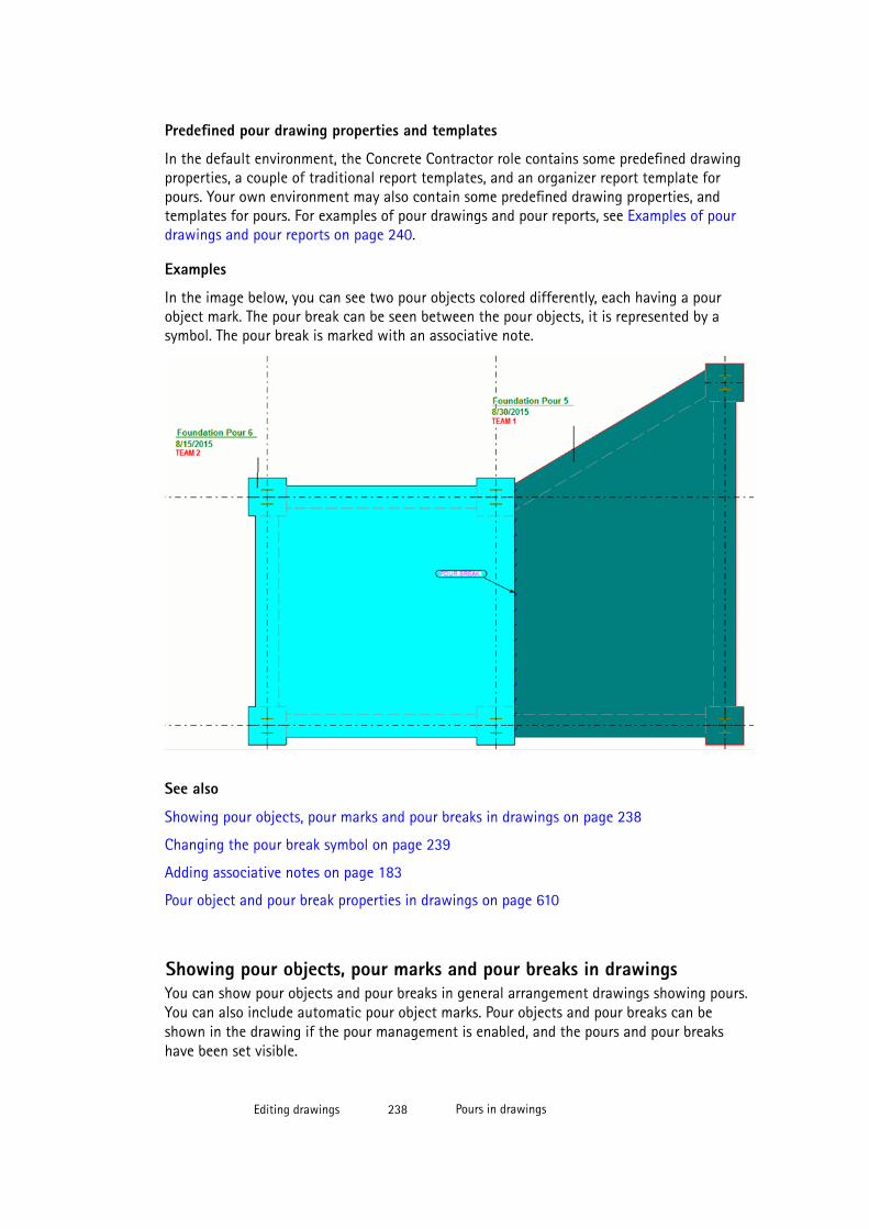
Predefined pour drawing properties and templates
In the default environment, the Concrete Contractor role contains some predefined drawingproperties, a couple of traditional report templates, and an organizer report template forpours. Your own environment may also contain some predefined drawing properties, andtemplates for pours. For examples of pour drawings and pour reports, see Examples of pourdrawings and pour reports on page 240.
Examples
In the image below, you can see two pour objects colored differently, each having a pourobject mark. The pour break can be seen between the pour objects, it is represented by asymbol. The pour break is marked with an associative note.
See also
Showing pour objects, pour marks and pour breaks in drawings on page 238
Changing the pour break symbol on page 239
Adding associative notes on page 183
Pour object and pour break properties in drawings on page 610
Showing pour objects, pour marks and pour breaks in drawingsYou can show pour objects and pour breaks in general arrangement drawings showing pours.You can also include automatic pour object marks. Pour objects and pour breaks can beshown in the drawing if the pour management is enabled, and the pours and pour breakshave been set visible.
Editing drawings 238 Pours in drawings
Ensure that you have enabled pour management (set the advanced option XS_ENABLE_POUR_MANAGEMENT to TRUE.)
To show pour objects and pour breaks automatically, modify their appearance and add pourobject marks:
1. Click Drawings & Reports --> Drawing Settings --> General Arrangement Drawing .
2. Load the properties that you want to change.
3. Click the View button and set Show pours in drawings to Yes, and click OK.
4. Click the Pour object button to display the pour object properties and modify theproperties:
• Content tab: Select whether you want to see the hidden lines and own hidden lines,and the edge chamfers by clicking on or off.
• Appearance tab: Set the color and type for visible lines and hidden lines.
• Fill tab: Select the fill for the pour object face and/or pour object section face.
5. Click OK.
6. Click the Pour object mark button, select the contents and appearance of the mark, andclick OK.
7. Click the Pour breaks button and set the Visibility to Visible and click OK.
You can also select to display pour break hidden lines on the Visibility tab. On theAppearance tab you can change the color and type of the visible and hidden lines inpour breaks.
8. Modify the other properties as required. For example, click Reinforcement and set theVisibility of all reinforcing bars to Visible to show the reinforcement in the pourdrawing. .
9. Save the changed properties and click OK.
Now you can create the general arrangement drawing using the modified properties. Thepour objects, pour object marks and pour breaks are shown accordingly.
You can also open the pour drawing and modify the properties further on drawing, viewand object level.
See also
Pours in drawings on page 236
Pour object and pour break properties in drawings on page 610
Adding automatic hatch patterns on drawing objects on page 526
Examples of pour drawings and pour reports on page 240
Editing drawings 239 Pours in drawings
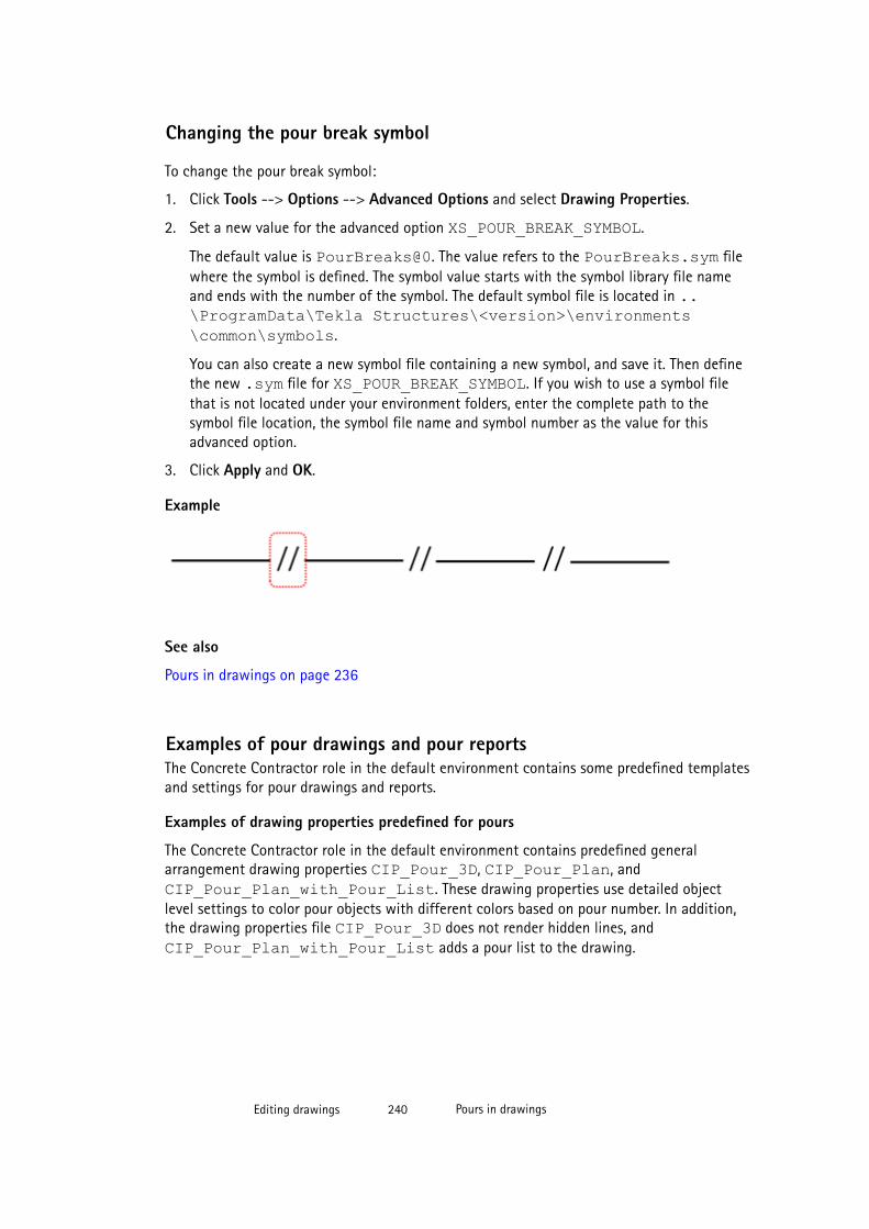
Changing the pour break symbol
To change the pour break symbol:
1. Click Tools --> Options --> Advanced Options and select Drawing Properties.
2. Set a new value for the advanced option XS_POUR_BREAK_SYMBOL.
The default value is PourBreaks@0. The value refers to the PourBreaks.sym filewhere the symbol is defined. The symbol value starts with the symbol library file nameand ends with the number of the symbol. The default symbol file is located in ..\ProgramData\Tekla Structures\<version>\environments\common\symbols.
You can also create a new symbol file containing a new symbol, and save it. Then definethe new .sym file for XS_POUR_BREAK_SYMBOL. If you wish to use a symbol filethat is not located under your environment folders, enter the complete path to thesymbol file location, the symbol file name and symbol number as the value for thisadvanced option.
3. Click Apply and OK.
Example
See also
Pours in drawings on page 236
Examples of pour drawings and pour reportsThe Concrete Contractor role in the default environment contains some predefined templatesand settings for pour drawings and reports.
Examples of drawing properties predefined for pours
The Concrete Contractor role in the default environment contains predefined generalarrangement drawing properties CIP_Pour_3D, CIP_Pour_Plan, andCIP_Pour_Plan_with_Pour_List. These drawing properties use detailed objectlevel settings to color pour objects with different colors based on pour number. In addition,the drawing properties file CIP_Pour_3D does not render hidden lines, andCIP_Pour_Plan_with_Pour_List adds a pour list to the drawing.
Editing drawings 240 Pours in drawings
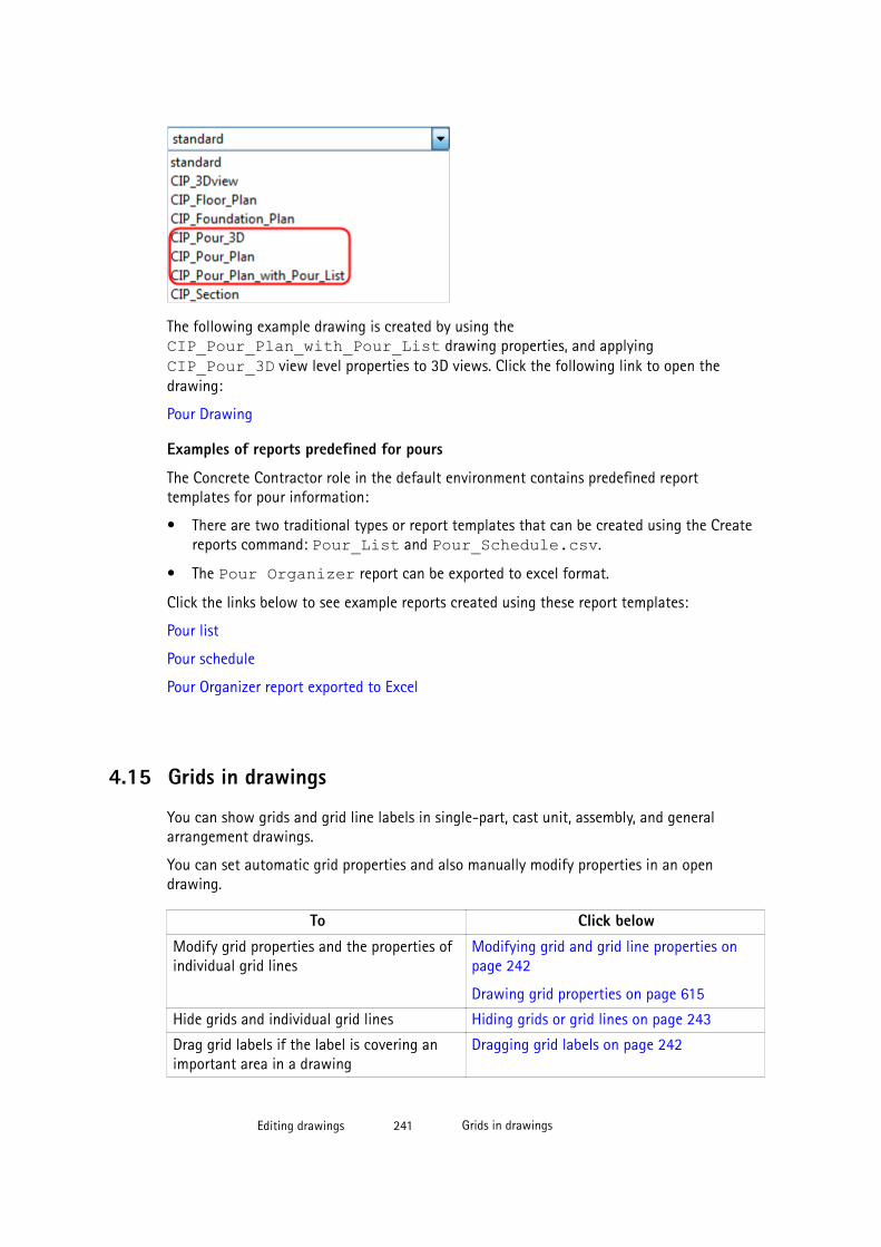
The following example drawing is created by using theCIP_Pour_Plan_with_Pour_List drawing properties, and applyingCIP_Pour_3D view level properties to 3D views. Click the following link to open thedrawing:
Pour Drawing
Examples of reports predefined for pours
The Concrete Contractor role in the default environment contains predefined reporttemplates for pour information:
• There are two traditional types or report templates that can be created using the Createreports command: Pour_List and Pour_Schedule.csv.
• The Pour Organizer report can be exported to excel format.
Click the links below to see example reports created using these report templates:
Pour list
Pour schedule
Pour Organizer report exported to Excel
4.15 Grids in drawings
You can show grids and grid line labels in single-part, cast unit, assembly, and generalarrangement drawings.
You can set automatic grid properties and also manually modify properties in an opendrawing.
To Click below
Modify grid properties and the properties ofindividual grid lines
Modifying grid and grid line properties onpage 242
Drawing grid properties on page 615
Hide grids and individual grid lines Hiding grids or grid lines on page 243
Drag grid labels if the label is covering animportant area in a drawing
Dragging grid labels on page 242
Editing drawings 241 Grids in drawings
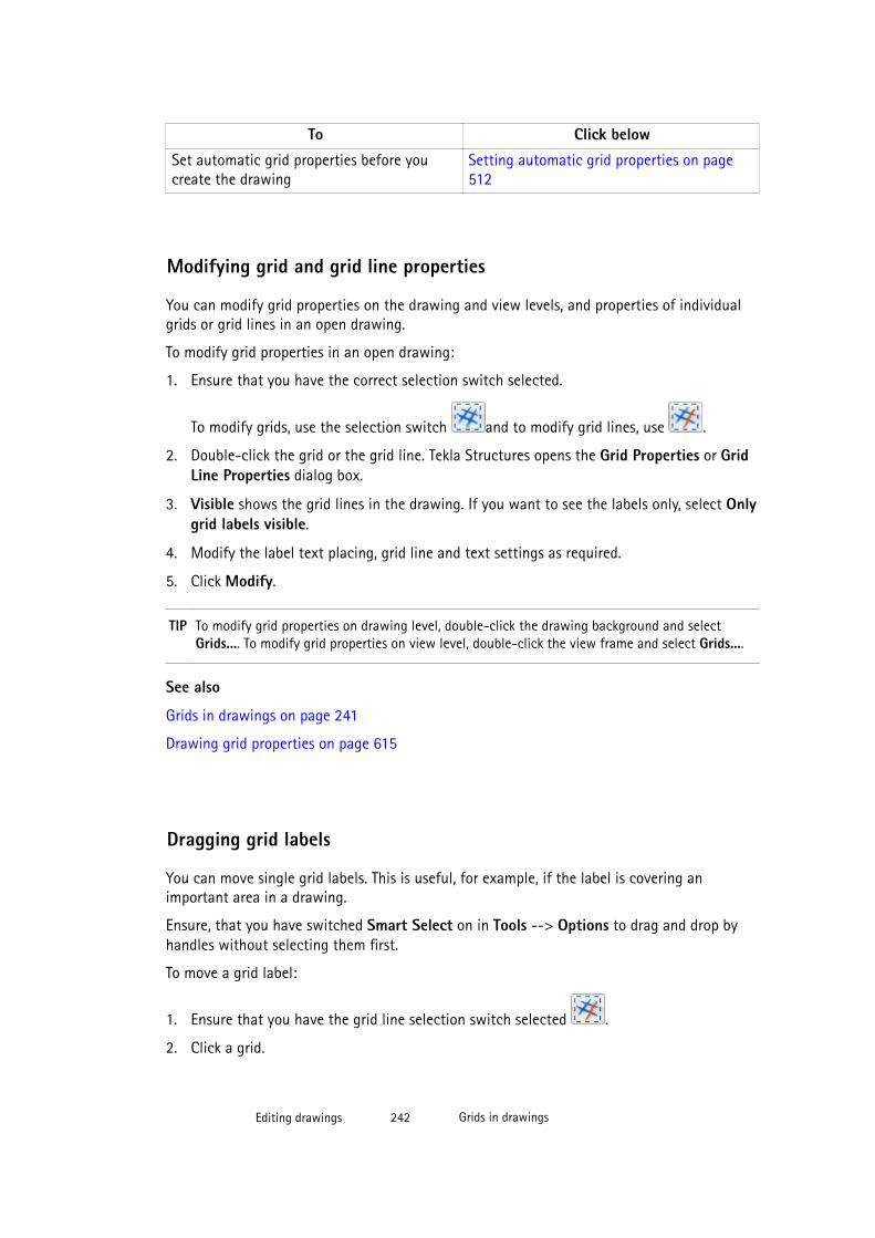
To Click below
Set automatic grid properties before youcreate the drawing
Setting automatic grid properties on page512
Modifying grid and grid line properties
You can modify grid properties on the drawing and view levels, and properties of individualgrids or grid lines in an open drawing.
To modify grid properties in an open drawing:
1. Ensure that you have the correct selection switch selected.
To modify grids, use the selection switch and to modify grid lines, use .
2. Double-click the grid or the grid line. Tekla Structures opens the Grid Properties or GridLine Properties dialog box.
3. Visible shows the grid lines in the drawing. If you want to see the labels only, select Onlygrid labels visible.
4. Modify the label text placing, grid line and text settings as required.
5. Click Modify.
TIP To modify grid properties on drawing level, double-click the drawing background and selectGrids.... To modify grid properties on view level, double-click the view frame and select Grids....
See also
Grids in drawings on page 241
Drawing grid properties on page 615
Dragging grid labels
You can move single grid labels. This is useful, for example, if the label is covering animportant area in a drawing.
Ensure, that you have switched Smart Select on in Tools --> Options to drag and drop byhandles without selecting them first.
To move a grid label:
1. Ensure that you have the grid line selection switch selected .
2. Click a grid.
Editing drawings 242 Grids in drawings
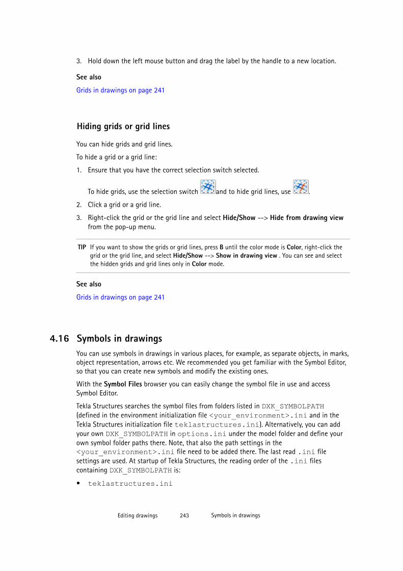
3. Hold down the left mouse button and drag the label by the handle to a new location.
See also
Grids in drawings on page 241
Hiding grids or grid lines
You can hide grids and grid lines.
To hide a grid or a grid line:
1. Ensure that you have the correct selection switch selected.
To hide grids, use the selection switch and to hide grid lines, use .
2. Click a grid or a grid line.
3. Right-click the grid or the grid line and select Hide/Show --> Hide from drawing viewfrom the pop-up menu.
TIP If you want to show the grids or grid lines, press B until the color mode is Color, right-click thegrid or the grid line, and select Hide/Show --> Show in drawing view . You can see and selectthe hidden grids and grid lines only in Color mode.
See also
Grids in drawings on page 241
4.16 Symbols in drawingsYou can use symbols in drawings in various places, for example, as separate objects, in marks,object representation, arrows etc. We recommended you get familiar with the Symbol Editor,so that you can create new symbols and modify the existing ones.
With the Symbol Files browser you can easily change the symbol file in use and accessSymbol Editor.
Tekla Structures searches the symbol files from folders listed in DXK_SYMBOLPATH(defined in the environment initialization file <your_environment>.ini and in theTekla Structures initialization file teklastructures.ini). Alternatively, you can addyour own DXK_SYMBOLPATH in options.ini under the model folder and define yourown symbol folder paths there. Note, that also the path settings in the<your_environment>.ini file need to be added there. The last read .ini filesettings are used. At startup of Tekla Structures, the reading order of the .ini filescontaining DXK_SYMBOLPATH is:
• teklastructures.ini
Editing drawings 243 Symbols in drawings

• <your_environment>.ini• options.iniAll symbol files that are found are available to be used in Tekla Structures. If there are symbolfiles with the same name, the one that is read last is used.
In addition to the symbols mentioned above, there are moment connection symbols that youcan manage with drawing tools.
See also
Creating and modifying symbol files on page 244
Adding symbols in drawings on page 246
Modifying symbol properties on page 246
Moment connection symbols in Tekla Structures drawings (Drawing tools) on page 247
Adding surface treatment symbols in drawings (AddSurfaceSymbols) on page 251
Adding symbols in marks on page 505
DXK_SYMBOLPATH
Defining a firm folder for images and symbols on page 541
Creating and using customized leader line arrows on page 190
Creating and modifying symbol files
The Symbol Files browser allows you to change the symbol file in use. It also provides accessto Symbol Editor, where you can create new symbol files, and create and modify symbols.
WARNING We strongly recommend that you do not modify the original symbol filesdelivered with your Tekla Structures application. If you need to modify anysymbols, copy the original symbol file and work on the copy, keeping theoriginal symbol file intact.
See also
Viewing and modifying symbol file contents on page 244
Creating a new symbol file on page 245
Changing the symbol file in use on page 245
Adding symbols in marks on page 505
Viewing and modifying symbol file contents
You can view and modify the contents of a symbol file.
To view or modify the contents of a symbol file:
Editing drawings 244 Symbols in drawings
1. Open the Mark content - symbol dialog box by selecting Symbol from the availablemark elements list in the mark properties dialog box, or open the Symbol propertiesdialog box by selecting Annotating --> Properties --> Symbol .
2. Click Select... next to the File box.
3. Select a file from the Symbol Files list and click Edit.
This opens the selected symbol file in Symbol Editor.
4. If you modify the file in the Symbol Editor, save the file : Click File --> Save or File -->Save As and give a new name.
5. Click OK.
TIP In Symbol Editor, you can copy symbols between symbol files (*.sym). Press Ctrl + C and selectthe symbol you would like to copy, then open the symbol file you want to copy to (or a newsymbol file), select the location for the symbol and press Ctrl + V.
See also
Creating and modifying symbol files on page 244
Creating a new symbol file
You can create new symbol files to be used in drawings.
To create a new symbol file:
1. Open the Mark content - symbol dialog box by selecting Symbol from the availablemark elements list in the mark properties dialog box or the Symbol properties dialog boxby selecting Annotating --> Properties --> Symbol .
2. Click Select... next to the File box.
3. In the Symbol Files dialog box, click Create new....
4. Create the symbol in the Symbol Editor.
5. Click File --> Save and save the symbol file in the folder that you use for keeping thesymbols.
6. Click Refresh in the Symbol Files browser.
See also
Creating and modifying symbol files on page 244
Changing the symbol file in use
You can change the currently used symbol file.
To change the symbol file in use:
Editing drawings 245 Symbols in drawings
1. Open the Mark content - symbol dialog box by selecting Symbol from the availablemark elements list in the mark properties dialog box, or the Symbol properties dialogbox by selecting Annotating --> Properties --> Symbol .
2. Click Select... next to the File box.
3. Select a new file from the Symbol Files list and click OK or double-click the file.
See also
Symbols in drawings on page 243
Creating and modifying symbol files on page 244
Adding symbols in drawings
Symbols added as separate objects are independent annotation objects. They can berepresented in three different ways: without leader lines, with leader lines and along lines.Tekla Structures adds symbols using the properties defined in the Symbol Properties dialogbox.
To add a symbol in a drawing:
1. In the drawing, hold down Shift and select Annotating --> Add Symbol and one of thethree symbol commands:
• Symbol: Add a symbol in the current drawing without a leader line.
• Symbol along Line: Create a symbol along the line you define by picking two points.Then pick an insertion point for the symbol.
• Symbol with Leader Line: Add a symbol with a leader line pointing to the point youpick first.
2. Modify other symbol properties.
3. Click OK.
4. Pick one to three points in the drawing to place the symbol. The symbol command youselected affects the number of points to pick.
See also
Symbols in drawings on page 243
Modifying symbol properties
You can modify the properties of symbols in an open drawing.
To modify the symbol properties:
1. Double-click a symbol.
Editing drawings 246 Symbols in drawings
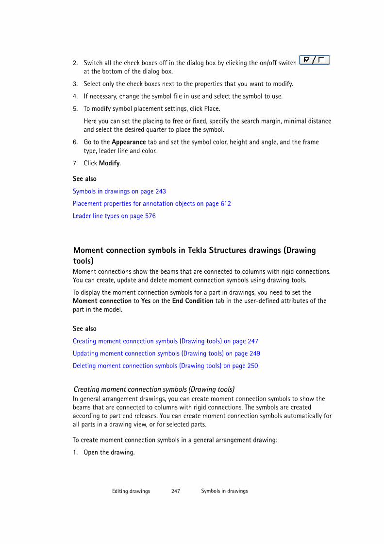
2. Switch all the check boxes off in the dialog box by clicking the on/off switch at the bottom of the dialog box.
3. Select only the check boxes next to the properties that you want to modify.
4. If necessary, change the symbol file in use and select the symbol to use.
5. To modify symbol placement settings, click Place.
Here you can set the placing to free or fixed, specify the search margin, minimal distanceand select the desired quarter to place the symbol.
6. Go to the Appearance tab and set the symbol color, height and angle, and the frametype, leader line and color.
7. Click Modify.
See also
Symbols in drawings on page 243
Placement properties for annotation objects on page 612
Leader line types on page 576
Moment connection symbols in Tekla Structures drawings (Drawingtools)Moment connections show the beams that are connected to columns with rigid connections.You can create, update and delete moment connection symbols using drawing tools.
To display the moment connection symbols for a part in drawings, you need to set theMoment connection to Yes on the End Condition tab in the user-defined attributes of thepart in the model.
See also
Creating moment connection symbols (Drawing tools) on page 247
Updating moment connection symbols (Drawing tools) on page 249
Deleting moment connection symbols (Drawing tools) on page 250
Creating moment connection symbols (Drawing tools)In general arrangement drawings, you can create moment connection symbols to show thebeams that are connected to columns with rigid connections. The symbols are createdaccording to part end releases. You can create moment connection symbols automatically forall parts in a drawing view, or for selected parts.
To create moment connection symbols in a general arrangement drawing:
1. Open the drawing.
Editing drawings 247 Symbols in drawings
2. Click the Applications and Components button in the upper-right corner of theTekla Structures main window to open the Applications and Components catalog.
3. Click the arrow next to Applications to open the applications list.
4. Double-click Drawing tools to display the Drawing tools toolbar.
5. Click Create moment connection symbols .
6. In the Create moment connection symbols dialog box, select the color for the symbolsfrom the color list.
7. Enter a scale for the symbols in the box next to the color list.
8. Do one of the following:
• To create moment connection symbols for all parts in a drawing view, select the view.
• To create moment connection symbols for selected parts, select the parts.
9. Click Create.
The moment connection symbols are created according to analysis part and connectionrelease properties:
• If a connection exists, start and end release information is read from the Start releasesand End releases tabs in the analysis part properties dialog box.
• If a connection does not exist, release information is read from the End conditions tab inthe user-defined attributes dialog box of the part.
Limitations
• Moment connection symbols are created to reference lines. This means that offsets arenot taken into use.
Editing drawings 248 Symbols in drawings
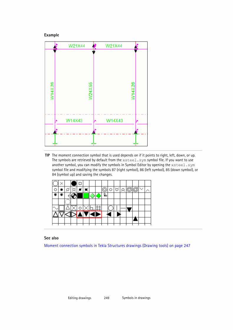
Example
TIP The moment connection symbol that is used depends on if it points to right, left, down, or up.The symbols are retrieved by default from the xsteel.sym symbol file. If you want to useanother symbol, you can modify the symbols in Symbol Editor by opening the xsteel.symsymbol file and modifying the symbols 87 (right symbol), 86 (left symbol), 85 (down symbol), or84 (symbol up) and saving the changes.
See also
Moment connection symbols in Tekla Structures drawings (Drawing tools) on page 247
Editing drawings 249 Symbols in drawings
Updating moment connection symbols (Drawing tools)
To update moment connection symbols:
1. Click the Applications and Components button in the upper-right corner of theTekla Structures main window to open the Applications and Components catalog.
2. Click the arrow next to Applications to open the applications list.
3. Double-click Drawing tools to display the Drawing tools toolbar.
4. Click Create moment connection symbols in the Drawing tools toolbar.
5. Do one of the following:
• To update the moment connection symbols of all parts in the view, select the view.
• To update the moment connection symbols of selected parts, select the parts.
6. Click Create.
When you do this, Tekla Structures removes all previously created symbols, and creates newones that are up-to-date.
See also
Moment connection symbols in Tekla Structures drawings (Drawing tools) on page 247
Deleting moment connection symbols (Drawing tools)
To delete moment connection symbols:
1. Click the Applications and Components button in the upper-right corner of theTekla Structures main window to open the Applications and Components catalog.
2. Click the arrow next to Applications to open the applications list.
3. Double-click Drawing tools to display the Drawing tools toolbar.
4. Click Create moment connection symbols .
5. Do one of the following:
• To delete the moment connection symbols of all parts in the view, select the view.
• To delete the moment connection symbols of selected parts, select the parts.
6. Click Delete.
See also
Moment connection symbols in Tekla Structures drawings (Drawing tools) on page 247
Editing drawings 250 Symbols in drawings
Adding surface treatment symbols in drawings (AddSurfaceSymbols)You can add surface treatment symbols in cast unit drawings using theAddSurfaceSymbols macro.
Before you start, ensure that you have an object that has surface treatment in the model,and that you have created a cast unit drawing of that object. Also check in the surfacetreatment drawing properties that the surface treatment is set to Visible.
To add surface treatment symbols in a part in a drawing:
1. Open a drawing that has a part containing surface treatment.
2. Click the Applications and Components button in the upper-right corner of theTekla Structures main window to open the Applications and Components catalog.
3. Click the arrow next to Applications to open the applications list.
4. Double-click AddSurfaceSymbols.
5. In the Create surface symbols dialog box, select the texts that you want to include inthe surface treatment symbol from the Available Elements list and add the texts to theElements in mark by clicking Add.
6. Select All views to include the symbols in all drawing views, or Selected views to includethe symbols only in the views you select.
7. Change the font settings, if necessary.
8. If you selected Selected views, select the views where you wish to have surfacetreatment symbols.
9. Click Create.
Editing drawings 251 Symbols in drawings
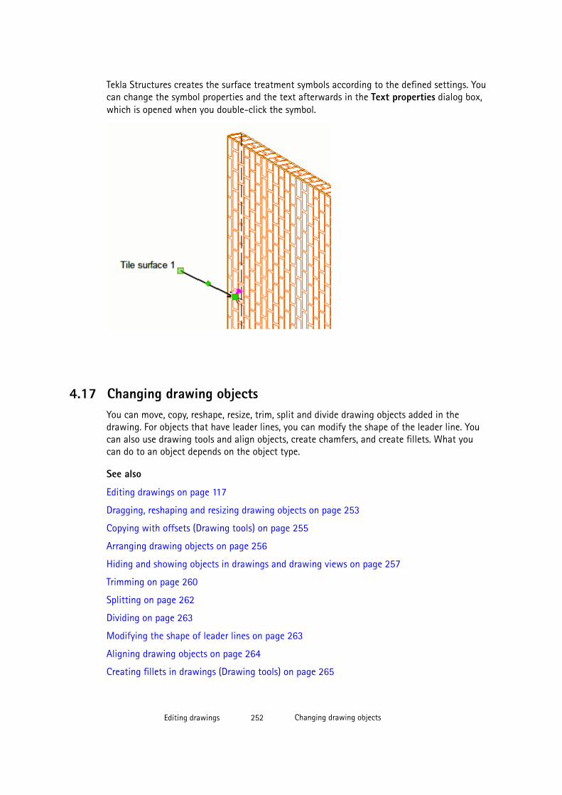
Tekla Structures creates the surface treatment symbols according to the defined settings. Youcan change the symbol properties and the text afterwards in the Text properties dialog box,which is opened when you double-click the symbol.
4.17 Changing drawing objectsYou can move, copy, reshape, resize, trim, split and divide drawing objects added in thedrawing. For objects that have leader lines, you can modify the shape of the leader line. Youcan also use drawing tools and align objects, create chamfers, and create fillets. What youcan do to an object depends on the object type.
See also
Editing drawings on page 117
Dragging, reshaping and resizing drawing objects on page 253
Copying with offsets (Drawing tools) on page 255
Arranging drawing objects on page 256
Hiding and showing objects in drawings and drawing views on page 257
Trimming on page 260
Splitting on page 262
Dividing on page 263
Modifying the shape of leader lines on page 263
Aligning drawing objects on page 264
Creating fillets in drawings (Drawing tools) on page 265
Editing drawings 252 Changing drawing objects
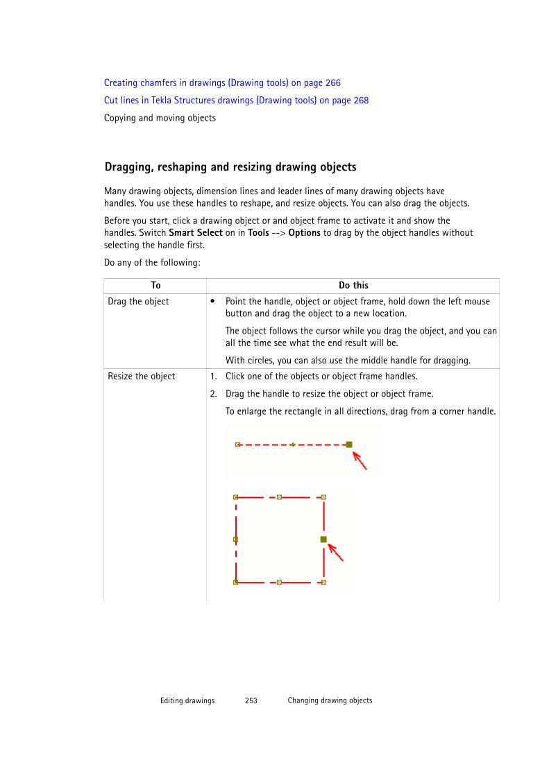
Creating chamfers in drawings (Drawing tools) on page 266
Cut lines in Tekla Structures drawings (Drawing tools) on page 268
Copying and moving objects
Dragging, reshaping and resizing drawing objects
Many drawing objects, dimension lines and leader lines of many drawing objects havehandles. You use these handles to reshape, and resize objects. You can also drag the objects.
Before you start, click a drawing object or and object frame to activate it and show thehandles. Switch Smart Select on in Tools --> Options to drag by the object handles withoutselecting the handle first.
Do any of the following:
To Do this
Drag the object • Point the handle, object or object frame, hold down the left mousebutton and drag the object to a new location.
The object follows the cursor while you drag the object, and you canall the time see what the end result will be.
With circles, you can also use the middle handle for dragging.
Resize the object 1. Click one of the objects or object frame handles.
2. Drag the handle to resize the object or object frame.
To enlarge the rectangle in all directions, drag from a corner handle.
Editing drawings 253 Changing drawing objects
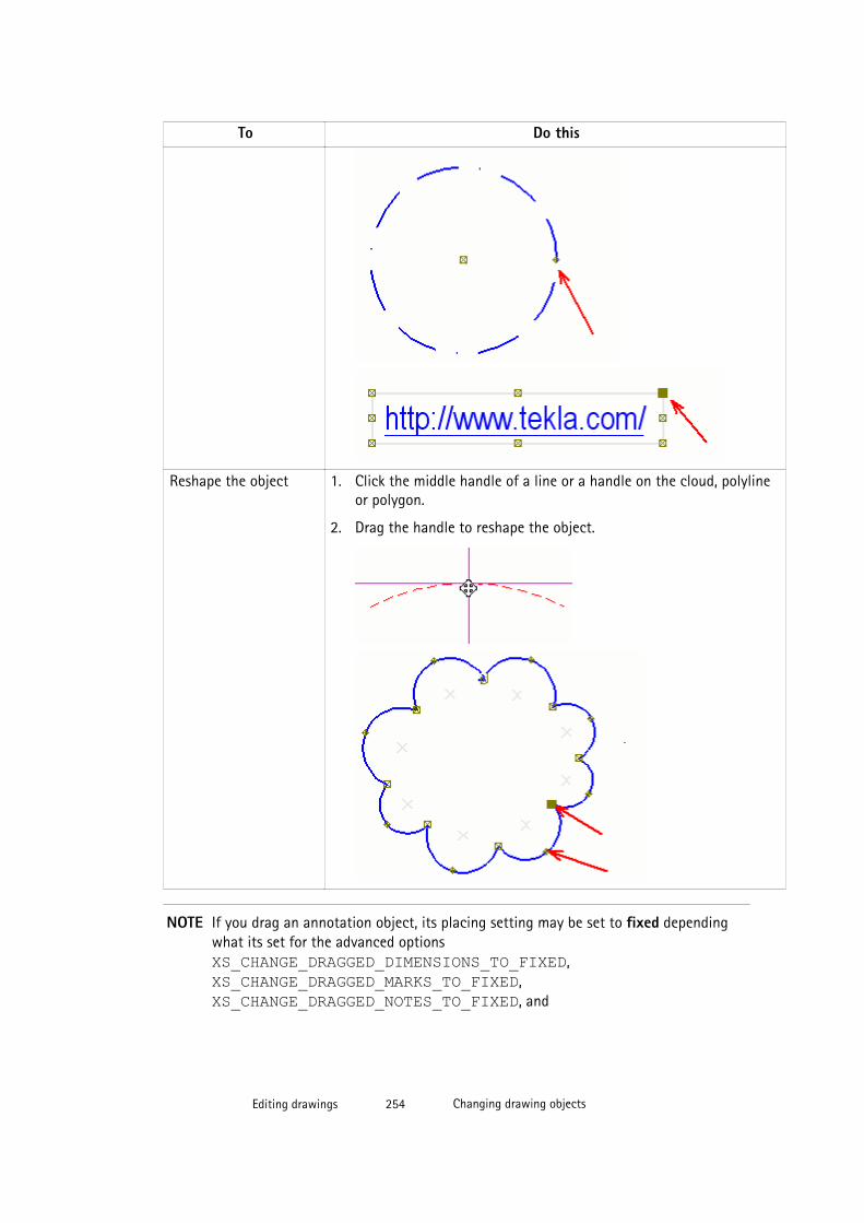
To Do this
Reshape the object 1. Click the middle handle of a line or a handle on the cloud, polylineor polygon.
2. Drag the handle to reshape the object.
NOTE If you drag an annotation object, its placing setting may be set to fixed dependingwhat its set for the advanced options XS_CHANGE_DRAGGED_DIMENSIONS_TO_FIXED, XS_CHANGE_DRAGGED_MARKS_TO_FIXED, XS_CHANGE_DRAGGED_NOTES_TO_FIXED, and
Editing drawings 254 Changing drawing objects

XS_CHANGE_DRAGGED_TEXTS_TO_FIXED. This means that the annotationobject stays where it is even though you update the drawing.
See also
Changing drawing objects on page 252
Object protection and placement settings in drawings on page 357
XS_CHANGE_DRAGGED_DIMENSIONS_TO_FIXED
XS_CHANGE_DRAGGED_MARKS_TO_FIXED
XS_CHANGE_DRAGGED_NOTES_TO_FIXED
XS_CHANGE_DRAGGED_TEXTS_TO_FIXED
Copying with offsets (Drawing tools)You can copy lines, circles, polylines, polygons and rectangles with offsets. You can copy linesto a new location in the direction you point using the offset that you specify. You can alsocreate new circles centered in the same location as the original circle and adjust the radiusby the offset that you specify.
To copy with offset:
1. Click the Applications and Components button in the upper-right corner of theTekla Structures main window to open the Applications and Components catalog.
2. Click the arrow next to Applications to open the applications list.
3. Double-click Drawing tools.
4. Select the object that you want to copy.
5. Click Copy with Offset in the Drawing tools toolbar.
6. Enter the offset in the dialog box that is displayed.
7. Click the view in the direction where you want to copy the object. For example, if you arecopying a line, Tekla Structures makes a new copy of the line in the specified location.And if you are copying a circle, Tekla Structures creates a new circle that is centered inthe same location as the original circle, and adjusts the radius by the offset that youspecified.
Example
Example of a copied line:
Editing drawings 255 Changing drawing objects

Example of a copied circle:
Arranging drawing objects
You can use the Arrange Drawing Objects (Freeplace) command to position drawingobjects. Tekla Structures positions the objects using the protection properties set for thedrawing and the placing properties of each object type.
To arrange drawing objects:
1. Double-click the open drawing, click Protection..., check the drawing protectionproperties and modify them as required.
2. Click Modify.
3. Double-click drawing objects, and then click Place... to check and modify the placingsettings.
If the object is set to Fixed, the Arrange Drawing Objects command has no effect.
4. Click Modify.
5. In the drawing, select the drawing objects you want to arrange.
6. Do one of the following:
Editing drawings 256 Changing drawing objects
• Click View --> Arrange Drawing Objects (Freeplace) --> Near Current Locations .
Tekla Structures positions the selected drawing objects so that they do not overlapother objects. Objects located in a free location are not moved, and overlappingobjects are moved as close to the current location as possible.
• Click View --> Arrange Drawing Objects (Freeplace) --> Ignore CurrentLocations .
Tekla Structures positions the selected drawing objects so that they do not overlapwith other objects without checking the current location of the objects.
See also
Changing drawing objects on page 252
Object protection and placement settings in drawings on page 357
Hiding and showing objects in drawings and drawing viewsYou can hide selected drawing objects in drawings and drawing views. When you hide a part,Tekla Structures will hide all its related objects. Note that if an object is hidden in drawingviews it will not be printed.
To hide drawing objects:
1. Check that the ghost outline selection is the one that you need in Tools --> Options -->Ghost Outline . In colored drawings, hidden objects are shown as ghost outlines, if thissetting is selected. In grayscale and black and white drawings, hidden objects are notshown even if Ghost Outline is selected.
2. Select the desired color mode by pressing B.
3. Select the objects you want to hide.
4. Click View --> Hide/Show Object and one of the following options:
• Hide from Drawing View. Tekla Structures hides the selected object in the view youselect it.
• Hide from Drawing. Tekla Structures hides the selected object in all views.
Example
Below are some examples of the results with different combinations of selections.
Editing drawings 257 Changing drawing objects
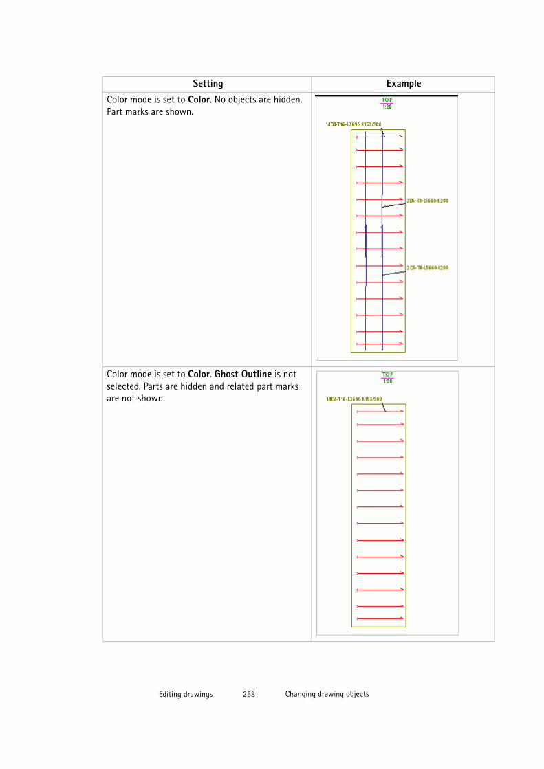
Setting Example
Color mode is set to Color. No objects are hidden.Part marks are shown.
Color mode is set to Color. Ghost Outline is notselected. Parts are hidden and related part marksare not shown.
Editing drawings 258 Changing drawing objects
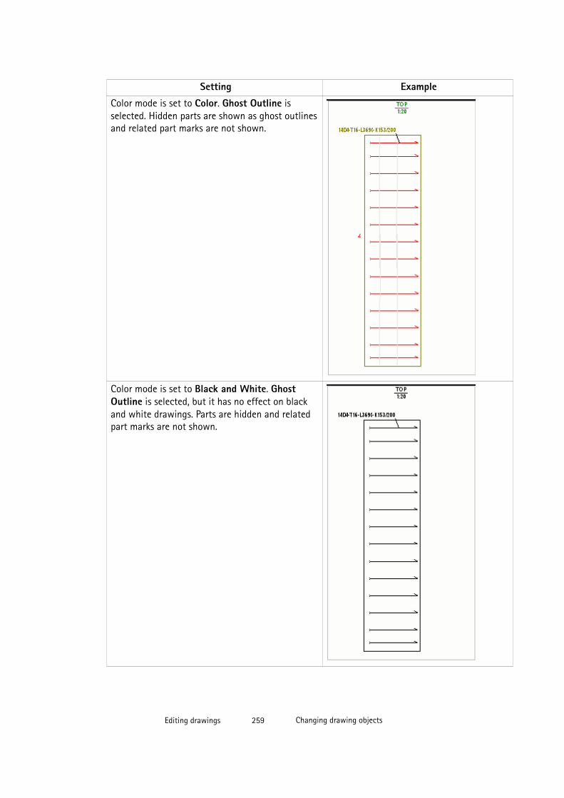
Setting Example
Color mode is set to Color. Ghost Outline isselected. Hidden parts are shown as ghost outlinesand related part marks are not shown.
Color mode is set to Black and White. GhostOutline is selected, but it has no effect on blackand white drawings. Parts are hidden and relatedpart marks are not shown.
Editing drawings 259 Changing drawing objects
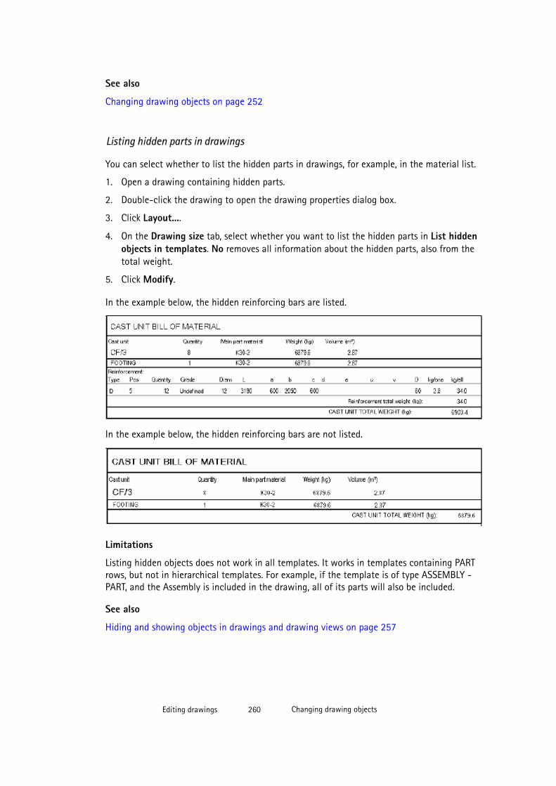
See also
Changing drawing objects on page 252
Listing hidden parts in drawings
You can select whether to list the hidden parts in drawings, for example, in the material list.
1. Open a drawing containing hidden parts.
2. Double-click the drawing to open the drawing properties dialog box.
3. Click Layout....
4. On the Drawing size tab, select whether you want to list the hidden parts in List hiddenobjects in templates. No removes all information about the hidden parts, also from thetotal weight.
5. Click Modify.
In the example below, the hidden reinforcing bars are listed.
In the example below, the hidden reinforcing bars are not listed.
Limitations
Listing hidden objects does not work in all templates. It works in templates containing PARTrows, but not in hierarchical templates. For example, if the template is of type ASSEMBLY -PART, and the Assembly is included in the drawing, all of its parts will also be included.
See also
Hiding and showing objects in drawings and drawing views on page 257
Editing drawings 260 Changing drawing objects
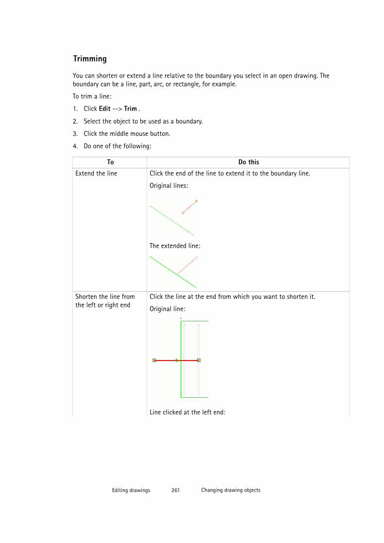
Trimming
You can shorten or extend a line relative to the boundary you select in an open drawing. Theboundary can be a line, part, arc, or rectangle, for example.
To trim a line:
1. Click Edit --> Trim .
2. Select the object to be used as a boundary.
3. Click the middle mouse button.
4. Do one of the following:
To Do this
Extend the line Click the end of the line to extend it to the boundary line.
Original lines:
The extended line:
Shorten the line fromthe left or right end
Click the line at the end from which you want to shorten it.
Original line:
Line clicked at the left end:
Editing drawings 261 Changing drawing objects
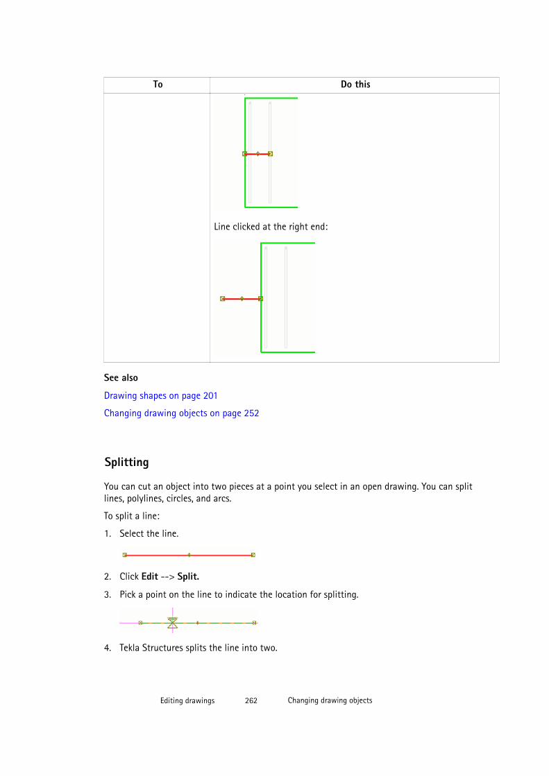
To Do this
Line clicked at the right end:
See also
Drawing shapes on page 201
Changing drawing objects on page 252
Splitting
You can cut an object into two pieces at a point you select in an open drawing. You can splitlines, polylines, circles, and arcs.
To split a line:
1. Select the line.
2. Click Edit --> Split.
3. Pick a point on the line to indicate the location for splitting.
4. Tekla Structures splits the line into two.
Editing drawings 262 Changing drawing objects
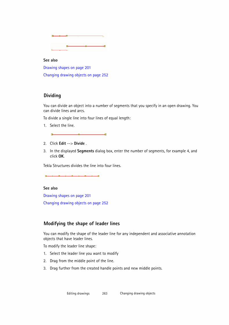
See also
Drawing shapes on page 201
Changing drawing objects on page 252
Dividing
You can divide an object into a number of segments that you specify in an open drawing. Youcan divide lines and arcs.
To divide a single line into four lines of equal length:
1. Select the line.
2. Click Edit --> Divide .
3. In the displayed Segments dialog box, enter the number of segments, for example 4, andclick OK.
Tekla Structures divides the line into four lines.
See also
Drawing shapes on page 201
Changing drawing objects on page 252
Modifying the shape of leader lines
You can modify the shape of the leader line for any independent and associative annotationobjects that have leader lines.
To modify the leader line shape:
1. Select the leader line you want to modify
2. Drag from the middle point of the line.
3. Drag further from the created handle points and new middle points.
Editing drawings 263 Changing drawing objects

See also
Additional ways for modifying part mark leader lines on page 484
Dragging the mark and associative note leader line base point on page 190
Changing drawing objects on page 252
Placing the base point of the reinforcement mark leader line automatically on page 485
Changing drawing objects on page 252
Aligning drawing objectsYou can align objects to the bottom, to the vertical center, to the left, to the horizontalcenter, to the right, and to the top. You can also position objects horizontally or vertically atequal distances from each other.
1. Open the Alignment toolbar from Tools --> Toolbars
2. Select the objects that you want to align.
3. Select the aligning command from the toolbar.
4. If you selected one of the two commands that position objects at equal distance, typethe distance in the displayed dialog box.
TIP To create a row of objects, align them first to the top and then position them horizontally atequal distances from each other. You do not need to reselect the objects between the twocommands.
Example
Below is an example where marks have been aligned to left.
Editing drawings 264 Changing drawing objects
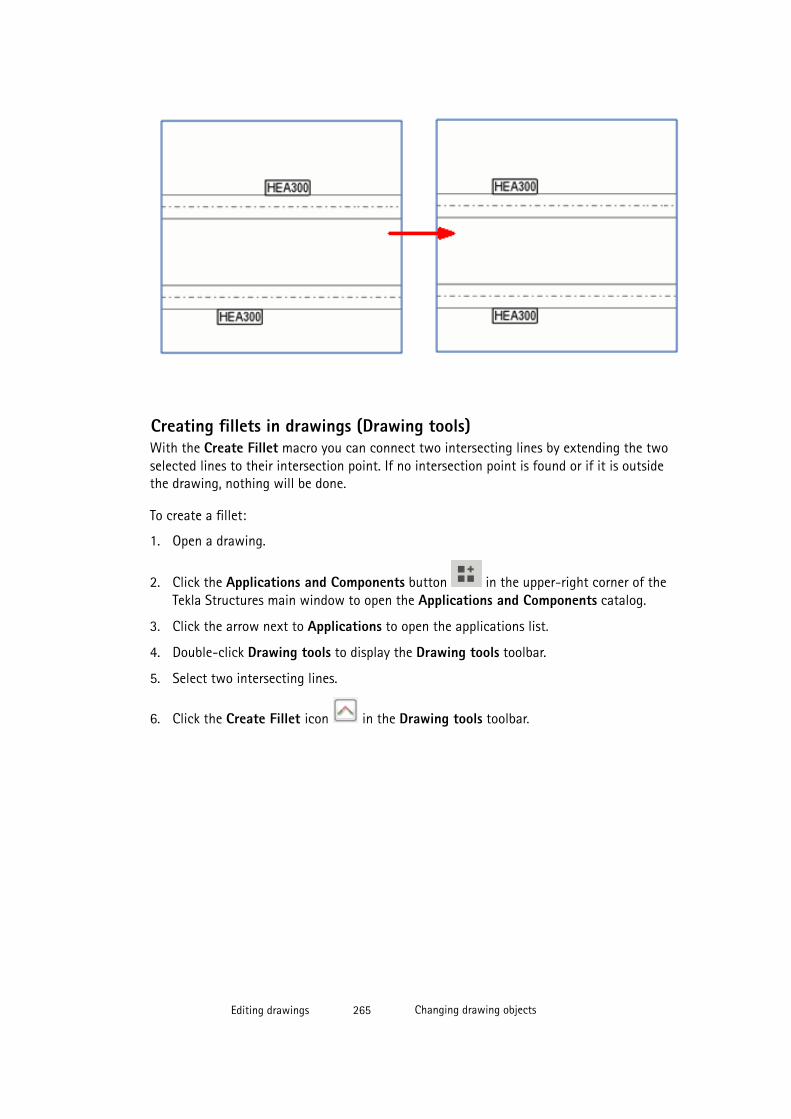
Creating fillets in drawings (Drawing tools)With the Create Fillet macro you can connect two intersecting lines by extending the twoselected lines to their intersection point. If no intersection point is found or if it is outsidethe drawing, nothing will be done.
To create a fillet:
1. Open a drawing.
2. Click the Applications and Components button in the upper-right corner of theTekla Structures main window to open the Applications and Components catalog.
3. Click the arrow next to Applications to open the applications list.
4. Double-click Drawing tools to display the Drawing tools toolbar.
5. Select two intersecting lines.
6. Click the Create Fillet icon in the Drawing tools toolbar.
Editing drawings 265 Changing drawing objects
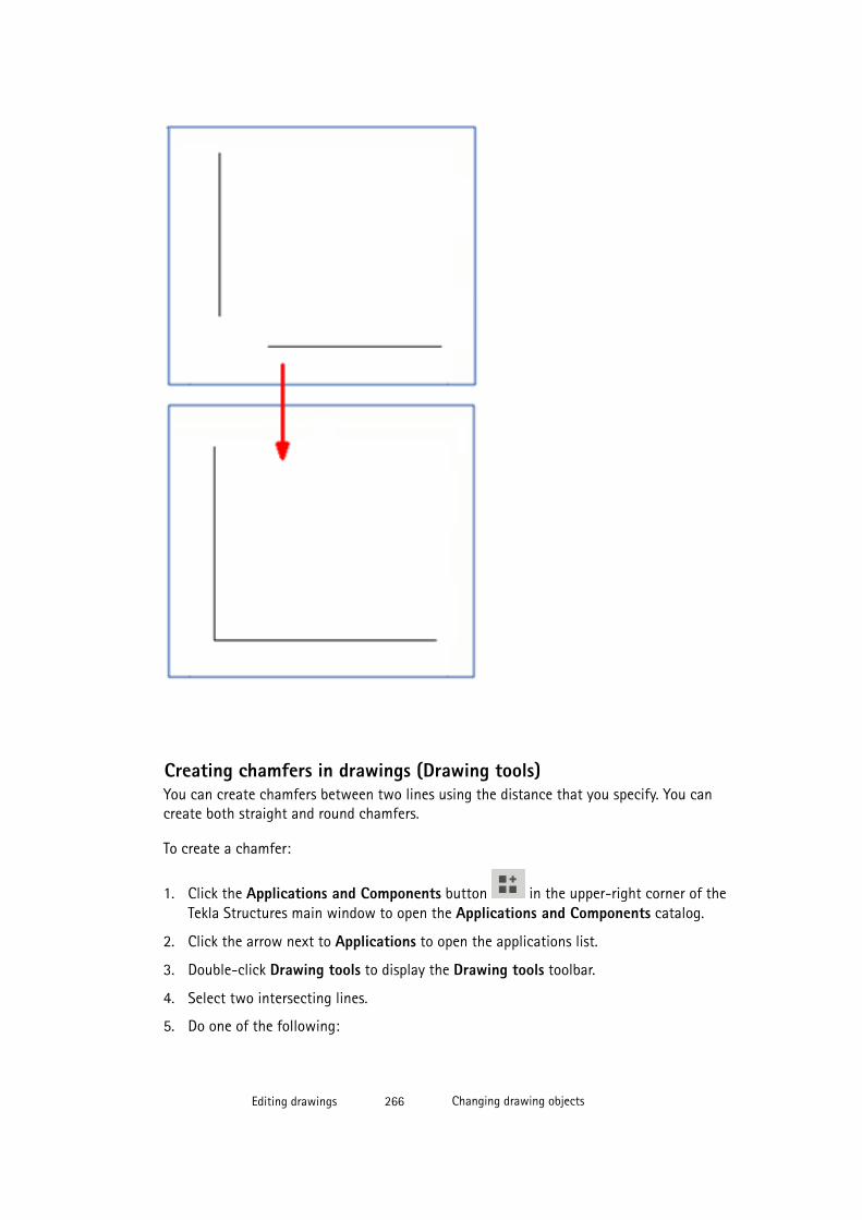
Creating chamfers in drawings (Drawing tools)You can create chamfers between two lines using the distance that you specify. You cancreate both straight and round chamfers.
To create a chamfer:
1. Click the Applications and Components button in the upper-right corner of theTekla Structures main window to open the Applications and Components catalog.
2. Click the arrow next to Applications to open the applications list.
3. Double-click Drawing tools to display the Drawing tools toolbar.
4. Select two intersecting lines.
5. Do one of the following:
Editing drawings 266 Changing drawing objects
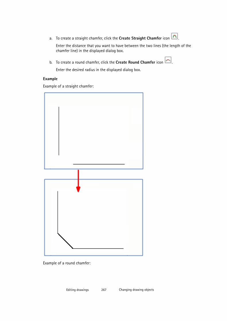
a. To create a straight chamfer, click the Create Straight Chamfer icon .
Enter the distance that you want to have between the two lines (the length of thechamfer line) in the displayed dialog box.
b. To create a round chamfer, click the Create Round Chamfer icon .
Enter the desired radius in the displayed dialog box.
Example
Example of a straight chamfer:
Example of a round chamfer:
Editing drawings 267 Changing drawing objects
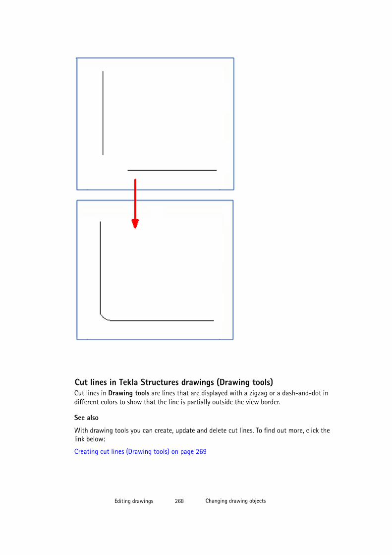
Cut lines in Tekla Structures drawings (Drawing tools)Cut lines in Drawing tools are lines that are displayed with a zigzag or a dash-and-dot indifferent colors to show that the line is partially outside the view border.
See also
With drawing tools you can create, update and delete cut lines. To find out more, click thelink below:
Creating cut lines (Drawing tools) on page 269
Editing drawings 268 Changing drawing objects

Updating cut lines (Drawing tools) on page 270
Deleting cut lines (Drawing tools) on page 270
Creating cut lines (Drawing tools)You can create cut lines to show the lines that are partially outside the view border usingdrawing tools. You can create cut lines automatically for all parts in the view, or for selectedparts.
To create cut lines:
1. Click the Applications and Components button in the upper-right corner of theTekla Structures main window to open the Applications and Components catalog.
2. Click the arrow next to Applications to open the applications list.
3. Double-click Drawing tools to display the Drawing tools toolbar.
4. Click Create cut lines .
5. Do any of the following:
• Select the type (zigzag or dash-and-dot) for the line from the list of types.
• Select the color for the line from the color list.
• Enter a scale for the line in the box next to the list of types.
6. Do one of the following:
• To create cut lines for all parts in the view, select the view.
• To create cut lines for selected parts, select the parts.
7. Click Create.
Limitations
• Cut lines cannot be created for polybeams.
• View extension for neighbor parts setting is not taken into account.
Example
Editing drawings 269 Changing drawing objects
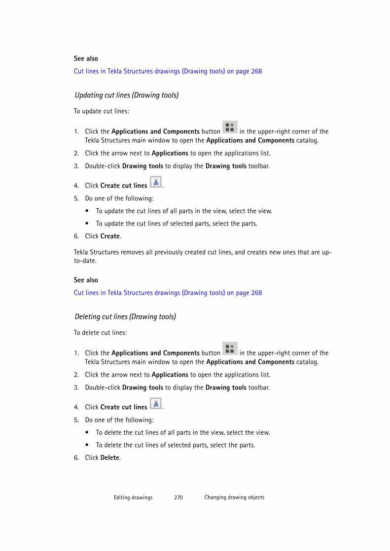
See also
Cut lines in Tekla Structures drawings (Drawing tools) on page 268
Updating cut lines (Drawing tools)
To update cut lines:
1. Click the Applications and Components button in the upper-right corner of theTekla Structures main window to open the Applications and Components catalog.
2. Click the arrow next to Applications to open the applications list.
3. Double-click Drawing tools to display the Drawing tools toolbar.
4. Click Create cut lines .
5. Do one of the following:
• To update the cut lines of all parts in the view, select the view.
• To update the cut lines of selected parts, select the parts.
6. Click Create.
Tekla Structures removes all previously created cut lines, and creates new ones that are up-to-date.
See also
Cut lines in Tekla Structures drawings (Drawing tools) on page 268
Deleting cut lines (Drawing tools)
To delete cut lines:
1. Click the Applications and Components button in the upper-right corner of theTekla Structures main window to open the Applications and Components catalog.
2. Click the arrow next to Applications to open the applications list.
3. Double-click Drawing tools to display the Drawing tools toolbar.
4. Click Create cut lines .
5. Do one of the following:
• To delete the cut lines of all parts in the view, select the view.
• To delete the cut lines of selected parts, select the parts.
6. Click Delete.
Editing drawings 270 Changing drawing objects

See also
Cut lines in Tekla Structures drawings (Drawing tools) on page 268
4.18 Colors in drawingsYou have three basic color modes for line colors in drawings. The color modes are Black andWhite, Gray Scale, and Color. By default, drawings are black and white.
In addition to the three basic color modes, you can have a black background and coloredlines in drawings (advanced option XS_BLACK_DRAWING_BACKGROUND).
Colors and gray shades
The table below shows the colors available in Tekla Structures, and how the different colorsare shown in black and white drawings and in grayscale drawings. The corresponding pennumbers referring to the line weights used in the printed drawings are also listed.
Name Pen Tekla Structures color Black and white Gray scale Lightness
Invisible 9 Invisible
Black 7 0%
Red 1 0%
Green 3 0%
Blue 5 0%
Cyan 4 0%
Yellow 2 0%
Magenta 6 0%
Brown 15 30%
Dark green 110 50%
Dark blue 141 70%
Blue-green 111 90%
Orange 31 100% white
Gray 8 60%
Special - -
See also
Changing drawing color on page 272
Specifying and using special color on page 273
Pen numbers in Color Table on page 274
Colors and line weights in printing on page 316
Editing drawings 271 Colors in drawings

Changing drawing color
You can change the color of the drawings.
To change the drawing color:
1. Open a drawing.
2. Click Tools --> Options --> Drawing Color Mode , and select Black and White, GrayScale or Color.
You can toggle between the color modes by pressing B on the keyboard.
TIP You can change the background color to black using the advanced option XS_BLACK_DRAWING_BACKGROUND. If the background is black, use Color ascolor mode.
Example
Below is an example of a color drawing.
In grayscale mode, the colors from 1 to 7 (black, red, green, blue, cyan, yellow, magenta) areshown in black, and the colors from 8 to 14 (brown, dark green, dark blue, blue-green,orange, gray) are shown in different shades of gray. Below is an example of a gray scaledrawing.
Editing drawings 272 Colors in drawings
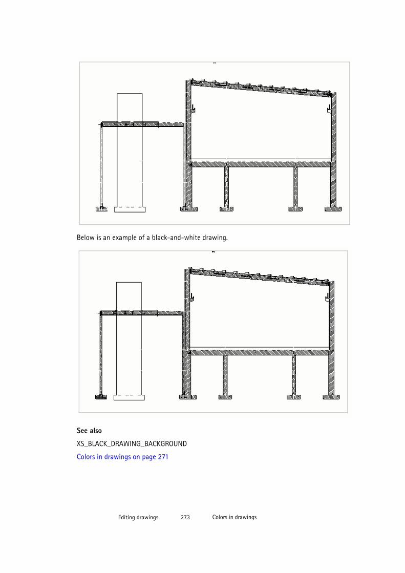
Below is an example of a black-and-white drawing.
See also
XS_BLACK_DRAWING_BACKGROUND
Colors in drawings on page 271
Editing drawings 273 Colors in drawings

Specifying and using special color
You can define a special color that is not converted to black when printed. This color will beprinted as color or grayscale, depending on the selected printer settings. The special color isdefined using RGB (Red Green Blue) values in a scale of 0 to 255. The special color is appliedon parts as a hatch.
You can specify a special color for a building object before creating a drawing, and use it inthe final drawing for shape or a building object.
To define and use a special color in a final drawing:
1. Click Tools --> Options --> Advanced Options... --> Hatching .
2. Define the color using the following advanced options:
• XS_HATCH_SPECIAL_COLOR_R• XS_HATCH_SPECIAL_COLOR_G• XS_HATCH_SPECIAL_COLOR_BThe default value for all of the above advanced options is 230.
The smaller the values are, the darker the shade.
3. Click OK or Apply.
4. Open a drawing.
5. Double-click a drawing object to open the properties dialog box. For example, click abuilding object or a rectangle.
6. Select a fill type.
7. Select the Special fill color.
8. Click Modify.
See also
Colors in drawings on page 271
Colors and line weights in printing on page 316
Pen numbers in Color TablePen numbers in the Color Table dialog box refer to the line weights used in the printeddrawing. By default, pen number 0 corresponds to a line weight of 0.1 mm. The final lineweight in a printed drawing is the default pen thickness multiplied by the pen number. Forexample, pen number 25 will give a line weight of 2.5 mm.
• The line thicknesses displayed on the screen are taken from the first printer instance onthe Printer instances list in the Printer Catalog. When you print a drawing, the linethickness is taken from the printer instance you use for printing.
Editing drawings 274 Colors in drawings

• In color drawings, the lines are shown with different thicknesses if the setting Tools -->Options --> Use Printer Linewidths is selected.
• In black and white drawings, Tekla Structures shows the black lines on the screen usingpen number thickness defined for the color in the Color Table.
• You can change the default pen thickness using the advanced option XS_BASE_LINE_WIDTH.
See also
XS_BASE_LINE_WIDTH
Changing the pen numbers for colors (line weight) on page 275
Colors in drawings on page 271
Changing the pen numbers for colors (line weight)
You can change the pen numbers for the colors to show and print lines with differentthicknesses.
To change the pen numbers:
1. Open a drawing.
2. Click Drawing File --> Print Drawings and go to the Line thickness tab.
3. Enter or change a pen number.
For example, to get line weight of 2.5 mm, enter 25. The preview shows the changed linethickness.
4. Click Close.
5. In a color drawing, click Tools --> Options and select Use Printer Linewidths, otherwiseyou cannot see the changes on the screen.
See also
Changing drawing color on page 272
Colors in drawings on page 271
Pen numbers in Color Table on page 274
XS_BASE_LINE_WIDTH
Editing drawings 275 User coordinate system (UCS)

4.19 User coordinate system (UCS)The UCS is a local user coordinate system you can use in a drawing view. It is easier toposition drawing objects in view, when you place objects relative to a user-defined point oforigin, or base point in the drawing view.
Tekla Structures shows the UCS symbol in the current drawing view, when you create, copy,move, or modify graphical objects.
You can define a different point of origin for the UCS for each drawing view, and change theUCS point of origin as often as you like.
The following example shows several views, each with their own UCS.
NOTE To position an object using the global coordinate system, you need to calculate thecoordinates of the object from the point of origin of the drawing.
See also
Adding manual dimensions using User Coordinate System on page 152
Setting a new UCS on page 277
Toggling between two user coordinate systems on page 277
Editing drawings 276 User coordinate system (UCS)
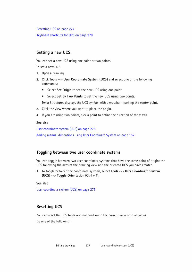
Resetting UCS on page 277
Keyboard shortcuts for UCS on page 278
Setting a new UCS
You can set a new UCS using one point or two points.
To set a new UCS:
1. Open a drawing.
2. Click Tools --> User Coordinate System (UCS) and select one of the followingcommands:
• Select Set Origin to set the new UCS using one point.
• Select Set by Two Points to set the new UCS using two points.
Tekla Structures displays the UCS symbol with a crosshair marking the center point.
3. Click the view where you want to place the origin.
4. If you are using two points, pick a point to define the direction of the x axis.
See also
User coordinate system (UCS) on page 275
Adding manual dimensions using User Coordinate System on page 152
Toggling between two user coordinate systems
You can toggle between two user coordinate systems that have the same point of origin: theUCS following the axes of the drawing view and the oriented UCS you have created.
• To toggle between the coordinate systems, select Tools --> User Coordinate System(UCS) --> Toggle Orientation (Ctrl + T).
See also
User coordinate system (UCS) on page 275
Resetting UCS
You can reset the UCS to its original position in the current view or in all views.
Do one of the following:
Editing drawings 277 User coordinate system (UCS)
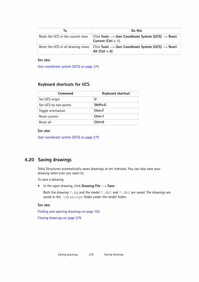
To Do this
Reset the UCS in the current view Click Tools --> User Coordinate System (UCS) --> ResetCurrent (Ctrl + 1).
Reset the UCS in all drawing views Click Tools --> User Coordinate System (UCS) --> ResetAll (Ctrl + 0).
See also
User coordinate system (UCS) on page 275
Keyboard shortcuts for UCS
Command Keyboard shortcut
Set UCS origin U
Set UCS by two points Shift+U
Toggle orientation Ctrl+T
Reset current Ctrl+1
Reset all Ctrl+0
See also
User coordinate system (UCS) on page 275
4.20 Saving drawings
Tekla Structures automatically saves drawings at set intervals. You can also save yourdrawing when ever you want to.
To save a drawing:
• In the open drawing, click Drawing File --> Save .
Both the drawing *.dg and the model *.db1 and *.db2 are saved. The drawings aresaved in the \drawings folder under the model folder.
See also
Finding and opening drawings on page 105
Closing drawings on page 279
Editing drawings 278 Saving drawings
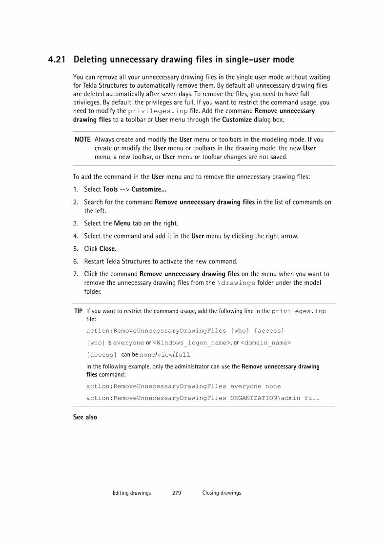
4.21 Deleting unnecessary drawing files in single-user mode
You can remove all your unneccessary drawing files in the single user mode without waitingfor Tekla Structures to automatically remove them. By default all unnecessary drawing filesare deleted automatically after seven days. To remove the files, you need to have fullprivileges. By default, the privileges are full. If you want to restrict the command usage, youneed to modify the privileges.inp file. Add the command Remove unnecessarydrawing files to a toolbar or User menu through the Customize dialog box.
NOTE Always create and modify the User menu or toolbars in the modeling mode. If youcreate or modify the User menu or toolbars in the drawing mode, the new Usermenu, a new toolbar, or User menu or toolbar changes are not saved.
To add the command in the User menu and to remove the unnecessary drawing files:
1. Select Tools --> Customize...
2. Search for the command Remove unnecessary drawing files in the list of commands onthe left.
3. Select the Menu tab on the right.
4. Select the command and add it in the User menu by clicking the right arrow.
5. Click Close.
6. Restart Tekla Structures to activate the new command.
7. Click the command Remove unnecessary drawing files on the menu when you want toremove the unnecessary drawing files from the \drawings folder under the modelfolder.
TIP If you want to restrict the command usage, add the following line in the privileges.inpfile:
action:RemoveUnnecessaryDrawingFiles [who] [access][who] is everyone or <Windows_logon_name>, or <domain_name>[access] can be none/view/full.
In the following example, only the administrator can use the Remove unnecessary drawingfiles command:
action:RemoveUnnecessaryDrawingFiles everyone noneaction:RemoveUnnecessaryDrawingFiles ORGANIZATION\admin full
See also
Editing drawings 279 Closing drawings

4.22 Closing drawings
You can only have one drawing open at a time. Tekla Structures always has to close an opendrawing before you can open another one.
To close a drawing:
1. Click the Close button in the upper-right corner of the drawing window.
2. If you have made changes in the drawing, Tekla Structures asks you to confirm if youwant to save your changes.
You can also select to freeze the drawing, and create a snapshot.
See also
Finding and opening drawings on page 105
Freezing drawings on page 284
Creating and viewing drawing snapshots on page 114
4.23 Keyboard shortcuts for drawings
Command Keyboard shortcut
Open Drawing list when a drawing is open Ctrl+O
Open Drawing list in model mode Ctrl+L
Open previous drawing Ctrl+Page Up
Open next drawing Ctrl+Page Down
Open any drawing after creating the drawing Ctrl+Shift
Associativity symbol Shift+A
Set next drawing color mode B
Ghost outline Shift+G
Add an orthogonal dimension G
Add free dimension F
In Drawing list: Open user-defined attributes Alt+U
In Drawing list: Add to Master Drawing Catalog Ctrl+M
In Drawing list: Revision Ctrl+R
In Master Drawing Catalog: Select all Ctrl+A
In Master Drawing Catalog: Create drawings for allparts
Alt+A
In Master Drawing Catalog: Create drawings Alt+C
Editing drawings 280 Keyboard shortcuts for drawings

See also
Editing drawings on page 117
Assigning a keyboard shortcut for a command
Editing drawings 281 Keyboard shortcuts for drawings
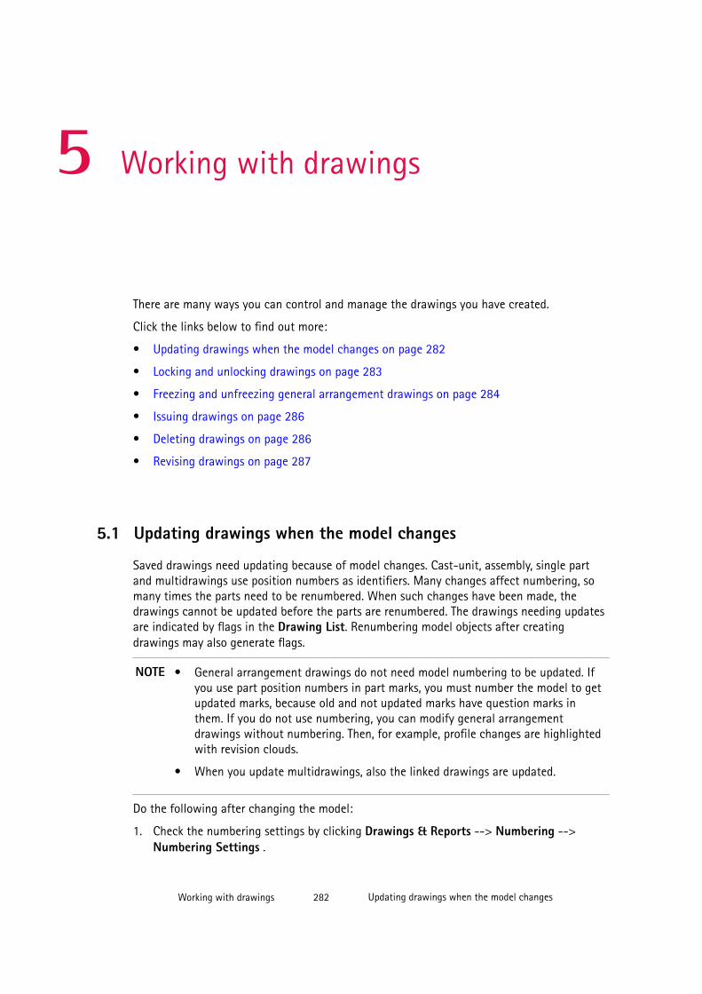
5 Working with drawings
There are many ways you can control and manage the drawings you have created.
Click the links below to find out more:
• Updating drawings when the model changes on page 282
• Locking and unlocking drawings on page 283
• Freezing and unfreezing general arrangement drawings on page 284
• Issuing drawings on page 286
• Deleting drawings on page 286
• Revising drawings on page 287
5.1 Updating drawings when the model changes
Saved drawings need updating because of model changes. Cast-unit, assembly, single partand multidrawings use position numbers as identifiers. Many changes affect numbering, somany times the parts need to be renumbered. When such changes have been made, thedrawings cannot be updated before the parts are renumbered. The drawings needing updatesare indicated by flags in the Drawing List. Renumbering model objects after creatingdrawings may also generate flags.
NOTE • General arrangement drawings do not need model numbering to be updated. Ifyou use part position numbers in part marks, you must number the model to getupdated marks, because old and not updated marks have question marks inthem. If you do not use numbering, you can modify general arrangementdrawings without numbering. Then, for example, profile changes are highlightedwith revision clouds.
• When you update multidrawings, also the linked drawings are updated.
Do the following after changing the model:
1. Check the numbering settings by clicking Drawings & Reports --> Numbering -->Numbering Settings .
Working with drawings 282 Updating drawings when the model changes
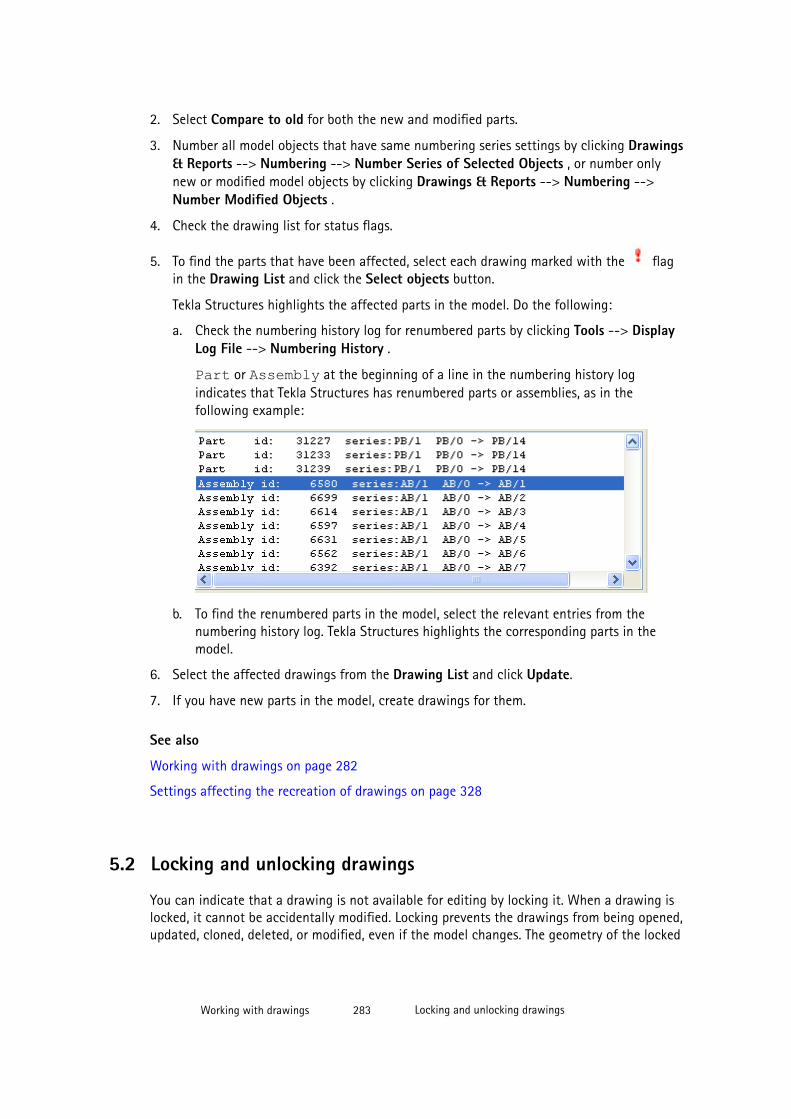
2. Select Compare to old for both the new and modified parts.
3. Number all model objects that have same numbering series settings by clicking Drawings& Reports --> Numbering --> Number Series of Selected Objects , or number onlynew or modified model objects by clicking Drawings & Reports --> Numbering -->Number Modified Objects .
4. Check the drawing list for status flags.
5. To find the parts that have been affected, select each drawing marked with the flagin the Drawing List and click the Select objects button.
Tekla Structures highlights the affected parts in the model. Do the following:
a. Check the numbering history log for renumbered parts by clicking Tools --> DisplayLog File --> Numbering History .
Part or Assembly at the beginning of a line in the numbering history logindicates that Tekla Structures has renumbered parts or assemblies, as in thefollowing example:
b. To find the renumbered parts in the model, select the relevant entries from thenumbering history log. Tekla Structures highlights the corresponding parts in themodel.
6. Select the affected drawings from the Drawing List and click Update.
7. If you have new parts in the model, create drawings for them.
See also
Working with drawings on page 282
Settings affecting the recreation of drawings on page 328
5.2 Locking and unlocking drawings
You can indicate that a drawing is not available for editing by locking it. When a drawing islocked, it cannot be accidentally modified. Locking prevents the drawings from being opened,updated, cloned, deleted, or modified, even if the model changes. The geometry of the locked
Working with drawings 283 Locking and unlocking drawings

drawing still changes when the model changes.Tekla Structures flags locked drawings forupdate if the model changes.
To lock and unlock drawings:
1. In the Drawing List, select the drawing(s) you want to lock.
2. Click Lock --> On .
The Locked by column in the Drawing List shows who has locked the drawing. If youhave logged in to your Tekla account, the account name is shown. Otherwise the username is shown.
3. To unlock the drawings, select the drawings and click Lock --> Off .
See also
Working with drawings on page 282
Selecting drawings in the Drawing List on page 112
5.3 Freezing drawingsYou can select whether to allow Tekla Structures to update all associative objects on top ofthe drawing views. The geometry of the model is always updated, but freezing is used to stopthe drawing intelligence (associativity) of drawing objects on top of the model views, andprevents them from being updated. For example, parts are updated, but dimensions, marks,views, and shapes are not.
See also
Freezing and unfreezing general arrangement drawings on page 284
Freezing and unfreezing single part, cast unit and assembly drawings on page 285
How freezing affects drawings on page 285
Working with drawings on page 282
Selecting drawings in the Drawing List on page 112
Updating marks on page 185
Freezing and unfreezing general arrangement drawings
To freeze a general arrangement drawing:
1. If you have the drawing open, close it without saving it.
2. In the Drawing List, select the drawing you want to freeze.
3. Click Freeze --> On .
Working with drawings 284 Freezing drawings

4. When freezing is no longer necessary, select the frozen drawings and click Freeze -->Off .
See also
Freezing drawings on page 284
Freezing and unfreezing single part, cast unit and assembly drawings
To freeze and unfreeze single part, cast unit and assembly drawings:
1. Save the model.
2. Open a drawing.
3. If the drawing does not look the way you want, close it without saving it.
4. Reopen the model. Do not save it.
5. In the Drawing List, select the drawing you want to freeze.
6. Click Freeze --> On .
7. Open the drawing.
8. When freezing is no longer necessary, select the frozen drawings and click Freeze -->Off .
See also
Freezing drawings on page 284
How freezing affects drawings on page 285
How freezing affects drawings
Freezing affects drawings in the following way:
• The associativity does not disappear from a frozen drawing. When you unfreeze thedrawing, the associativity works again.
• Freezing does not have any effect on the cloning result. If you edit the drawing, it doesnot matter whether you freeze the drawing before or after editing it.
• If a drawing is frozen, the associative drawing objects are not updated when the drawingis updated. This means that the dimensions and views are not updated, and the marks donot follow the parts if the parts have been moved.
• If a drawing is frozen, and the part changes in the model, the geometry of the part isupdated in the frozen drawing when the drawing is updated.
Working with drawings 285 Freezing drawings

• Unfreezing the drawing before cloning does not have any effect on the cloning result.This means, for example, that it does not matter whether you keep the drawing frozen allthe time or temporarily unfreeze it before cloning.
• If you unfreeze a drawing before update, the drawing is updated normally.
See also
Freezing drawings on page 284
5.4 Issuing drawings
When a drawing is released for fabrication, it should be marked as issued in the DrawingList. The geometry of the issued drawings is updated when the model changes. Issuing onlyprevents the recreation of the drawing during update. The issuing information can be used tofilter the Drawing List and in templates.
To issue drawings:
1. In the Drawing List, select the drawings to be issued.
2. Select Issue --> On .
Tekla Structures marks the issued drawings with a flag
When an issued drawing has been edited or otherwise changed, the color of the flag
changes and the text Issued drawing changed is displayed.
TIP To show the issue date in a report, add the template field DATE_ISSUE in the appropriatereport template.
See also
Working with drawings on page 282
DATE_ISSUE
5.5 Deleting drawings
You can delete drawings in the Drawing List.
1. In the Drawing List, select the drawings you want to delete.
2. Click Delete.
3. When Tekla Structures asks you to confirm the deletion, select Yes.
Working with drawings 286 Issuing drawings
TIP If you press down Shift, Tekla Structures will not ask you to confirm the deletion.
See also
Working with drawings on page 282
Selecting drawings in the Drawing List on page 112
5.6 Revising drawingsWhen you revise drawings, you can attach information to them about the changes you havemade. Tekla Structures displays this information alongside the revision number or mark. Therevision date also appears in the revision table within drawings. The revision number or markis also shown in the Drawing List by default. Revision information can also be used inreports.
You can revise drawings through the Drawing List or when the drawing is open. When yourevise the drawings using Add Revision Mark in an open drawing, Tekla Structures createsmarks in the drawing indicating the places where the changes have been made.
The report drawing_issue_rev.xsr shows the most recent revision dates of drawings.
TIP To show the revision mark instead of the revision number in the Drawing List, set the advancedoption XS_SHOW_REVISION_MARK_ON_DRAWING_LIST to TRUE.
See also
XS_SHOW_REVISION_MARK_ON_DRAWING_LIST
Adding revision marks on page 200
Creating revisions on page 287
Changing revisions on page 288
Deleting revisions on page 289
Creating revisions
You can create revisions to follow the changes in the drawing.
To create a revision:
1. In the Drawing List, select the drawings to revise.
2. Click Revision....
The Revision Handling dialog box is displayed.
Working with drawings 287 Revising drawings
3. Enter a mark in the Mark box.
Marks can be numerical or alphabetical such as 1, 2, 3… or A, B, C…
4. Fill in the Created by information and select the creation date from the calendar that isdisplayed when you click the down-arrow next to the Date option.
5. If you need to give information about who checked and approved the drawing, enter theinformation in the corresponding boxes and select the appropriate dates.
6. Enter a revision description in the Description box.
7. Enter delivery information in the Delivery box.
8. Enter any additional information in the Info 1 and Info 2 boxes.
9. Click Create.
The revision number or mark is now displayed in the Drawing List. When you open thedrawing, you can see the revision information in the revision table if there is one in thedrawing.
TIP Each drawing has its own unique revision number, but several drawings can share the samerevision mark, date, and other information. To attach the same revision information to severaldrawings simultaneously, select multiple drawings from the drawing list.
See also
Revising drawings on page 287
Revision handling attributes on page 289
Changing revisions
You can change revision information afterwards.
To change a revision:
1. Select a revised drawing from the Drawing List.
2. Click Revision....
3. In the Revision Handling dialog box, select the number of the revision that you want tochange from the Rev. No. list.
4. Change the revision information.
5. Click Modify.
6. Close the Revision Handling dialog box.
See also
Working with drawings on page 282
Revision handling attributes on page 289
Working with drawings 288 Revising drawings
Deleting revisions
You can delete unnecessary revisions.
To delete a revision:
1. Select a revised drawing from the Drawing List.
2. Click Revision....
3. In the Revision Handling dialog box, select the revision number from the list next to theMark box.
4. Click Delete.
When you delete a revision, Tekla Structures automatically adjusts the remaining revisionnumbers for that drawing. The revision marks do not change.
See also
Working with drawings on page 282
Revision handling attributes
The revision handling attributes can be included in drawing templates and report templates.All revision handling attributes and the corresponding options in the Revision Handlingdialog box are listed below.
Revision handling attribute Option in the Revision Handling dialog box
MARK The revision mark in the Mark box.
NUMBER The revision number in Rev. No.
CREATED_BY The Created by information of the revision.
DATE_CREATE Date next to Created by.
CHECKED_BY The Checked by information of the revision.
DATE_CHECKED Date next to Checked by.
APPROVED_BY The Approved by information of the revision.
DELIVERY The Delivery information of the revision.
DESCRIPTION The revision Description.
DATE_APPROVED Date next to Approved by.
INFO1 The Info 1 text of the revision.
INFO2 The Info 2 text of the revision.
LAST The revision number of the latest revision in Rev. No..
LAST_CREATED_BY The Created by information of the latest revision.
LAST_CHECKED_BY The Checked by information of the latest revision.
Working with drawings 289 Revising drawings
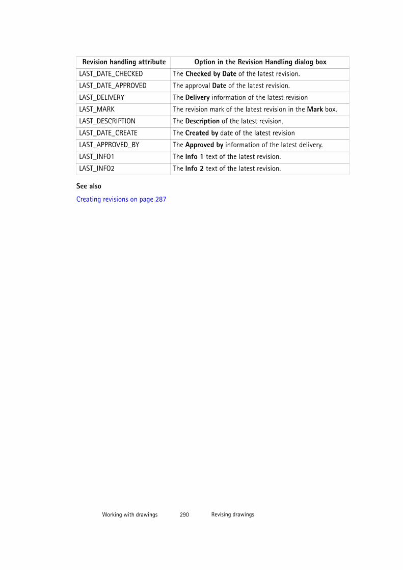
Revision handling attribute Option in the Revision Handling dialog box
LAST_DATE_CHECKED The Checked by Date of the latest revision.
LAST_DATE_APPROVED The approval Date of the latest revision.
LAST_DELIVERY The Delivery information of the latest revision
LAST_MARK The revision mark of the latest revision in the Mark box.
LAST_DESCRIPTION The Description of the latest revision.
LAST_DATE_CREATE The Created by date of the latest revision
LAST_APPROVED_BY The Approved by information of the latest delivery.
LAST_INFO1 The Info 1 text of the latest revision.
LAST_INFO2 The Info 2 text of the latest revision.
See also
Creating revisions on page 287
Working with drawings 290 Revising drawings
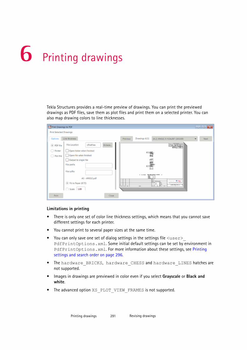
6 Printing drawings
Tekla Structures provides a real-time preview of drawings. You can print the previeweddrawings as PDF files, save them as plot files and print them on a selected printer. You canalso map drawing colors to line thicknesses.
Limitations in printing
• There is only one set of color line thickness settings, which means that you cannot savedifferent settings for each printer.
• You cannot print to several paper sizes at the same time.
• You can only save one set of dialog settings in the settings file <user>_PdfPrintOptions.xml. Some initial default settings can be set by environment inPdfPrintOptions.xml. For more information about these settings, see Printingsettings and search order on page 296.
• The hardware_BRICKS, hardware_CHESS and hardware_LINES hatches arenot supported.
• Images in drawings are previewed in color even if you select Grayscale or Black andwhite.
• The advanced option XS_PLOT_VIEW_FRAMES is not supported.
Printing drawings 291 Revising drawings
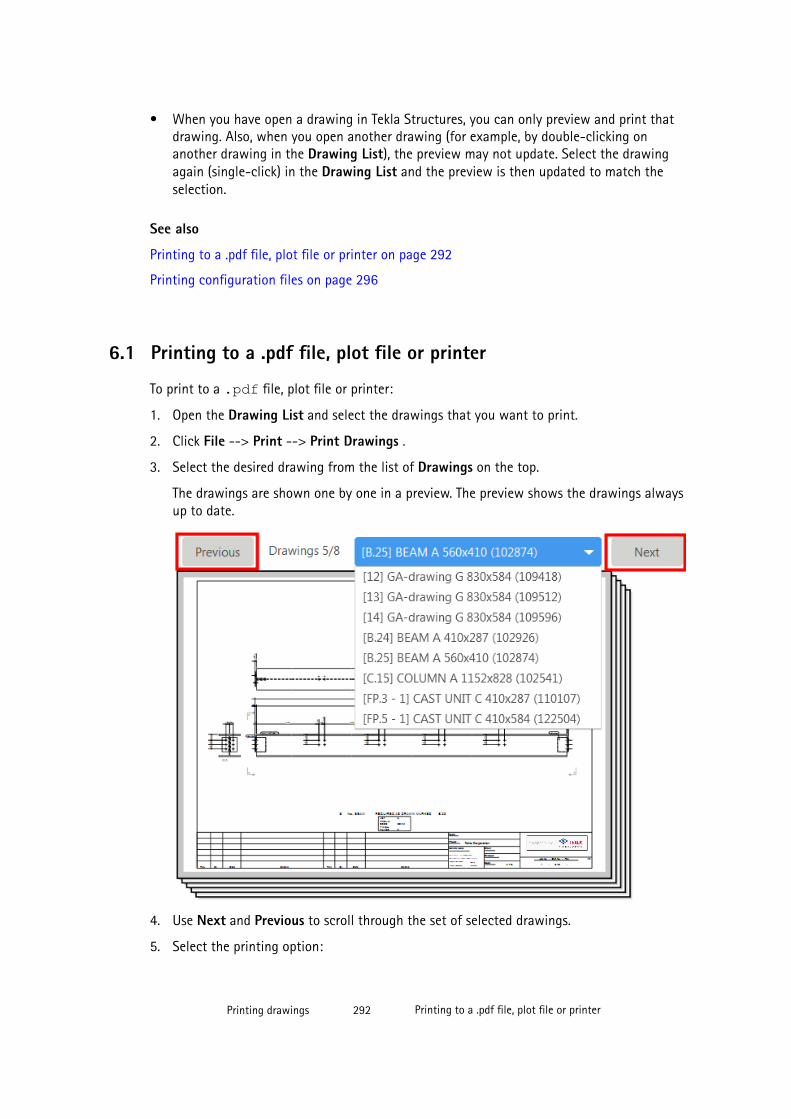
• When you have open a drawing in Tekla Structures, you can only preview and print thatdrawing. Also, when you open another drawing (for example, by double-clicking onanother drawing in the Drawing List), the preview may not update. Select the drawingagain (single-click) in the Drawing List and the preview is then updated to match theselection.
See also
Printing to a .pdf file, plot file or printer on page 292
Printing configuration files on page 296
6.1 Printing to a .pdf file, plot file or printer
To print to a .pdf file, plot file or printer:
1. Open the Drawing List and select the drawings that you want to print.
2. Click File --> Print --> Print Drawings .
3. Select the desired drawing from the list of Drawings on the top.
The drawings are shown one by one in a preview. The preview shows the drawings alwaysup to date.
4. Use Next and Previous to scroll through the set of selected drawings.
5. Select the printing option:
Printing drawings 292 Printing to a .pdf file, plot file or printer
• PDF file: Converts drawings to PDF format.
• Printer: Sends the drawings to the selected printer.
• Plot file: Converts drawings to print files in a format suitable for the selected printerand saves them in a specified location.
6. If you need to change Windows printing settings for a printer or for a plot file, click theProperties button.
7. Define the printing settings. The available settings depend on which printing option youhave selected:
• File location: Enter the location for the .pdf or plot file, or use Browse to browsefor the folder.
The \Plotfiles folder under the model folder is the default value.
• Open folder when finished: Opens the .pdf or plot file folder in Windows Explorerafter the printouts have been created.
• Open file when finished: Opens the .pdf file after it has been created.
• Output to single file: Prints the selected drawings to a single .pdf file.
If you do not select this option, each drawing will be printed in a .pdf file of itsown.
• File extension: Allows you to specify a file name extension for the plot file. Thedefault is plt.
• File prefix: Allows you to enter a specific prefix in the file name.
• File suffix: Allows you to enter a specific suffix in the file name.
When you enter a prefix or suffix, the file name preview displayed under the Fileprefix and File suffix boxes will reflect the change immediately.
The file name can be controlled by a couple of advanced option switches forcustomizing print file names, except when you generate a single combined multipledrawings .pdf file.
• Fit to paper: Fits the drawing to a specific paper size.
• Scale: Defines the scale to force the printout to a specific scale.
The Scale value will turn red if the drawing cannot fit on the specified sheet.
• Center drawing on paper: Centers the drawing on the sheet (or sheets).
• Print on multiple sheets: Allows you to print on multiple sheets and specifies thedirection of printing the sheets. Select either Left to right, top to bottom orBottom to top, right to left.
When you use Print on multiple sheets, select a particular paper size.
• Paper size: Defines the paper size or use automatic size.
With the Auto setting Tekla Structures selects the paper size that has the leastwasted area when the scaled print is fitted to the printable area on the sheet.
Printing drawings 293 Printing to a .pdf file, plot file or printer
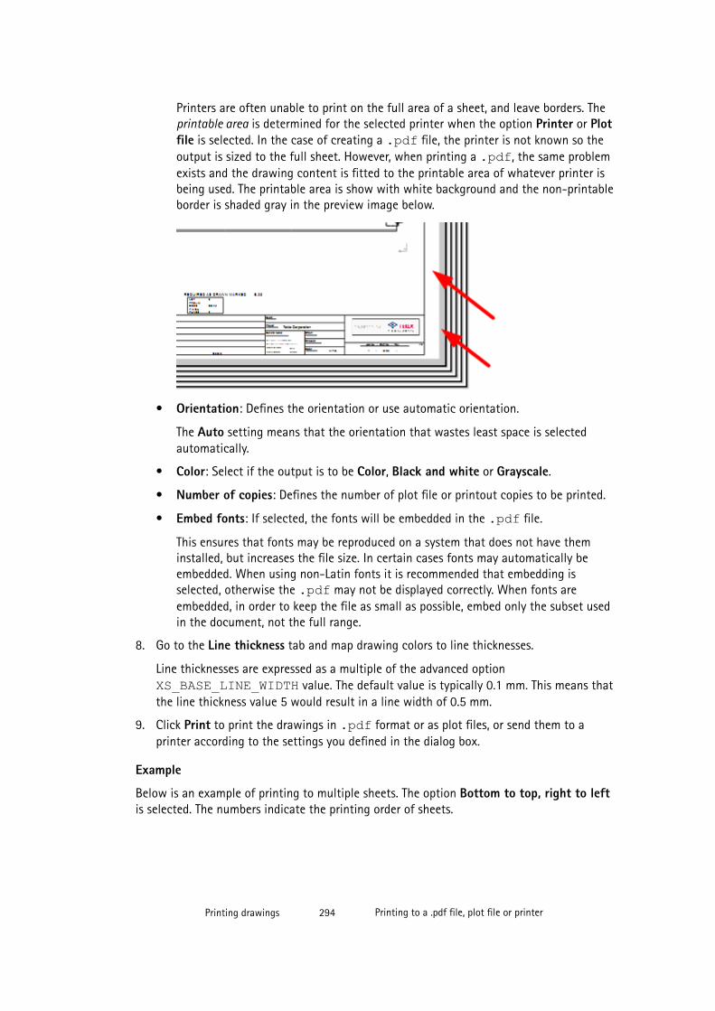
Printers are often unable to print on the full area of a sheet, and leave borders. Theprintable area is determined for the selected printer when the option Printer or Plotfile is selected. In the case of creating a .pdf file, the printer is not known so theoutput is sized to the full sheet. However, when printing a .pdf, the same problemexists and the drawing content is fitted to the printable area of whatever printer isbeing used. The printable area is show with white background and the non-printableborder is shaded gray in the preview image below.
• Orientation: Defines the orientation or use automatic orientation.
The Auto setting means that the orientation that wastes least space is selectedautomatically.
• Color: Select if the output is to be Color, Black and white or Grayscale.
• Number of copies: Defines the number of plot file or printout copies to be printed.
• Embed fonts: If selected, the fonts will be embedded in the .pdf file.
This ensures that fonts may be reproduced on a system that does not have theminstalled, but increases the file size. In certain cases fonts may automatically beembedded. When using non-Latin fonts it is recommended that embedding isselected, otherwise the .pdf may not be displayed correctly. When fonts areembedded, in order to keep the file as small as possible, embed only the subset usedin the document, not the full range.
8. Go to the Line thickness tab and map drawing colors to line thicknesses.
Line thicknesses are expressed as a multiple of the advanced option XS_BASE_LINE_WIDTH value. The default value is typically 0.1 mm. This means thatthe line thickness value 5 would result in a line width of 0.5 mm.
9. Click Print to print the drawings in .pdf format or as plot files, or send them to aprinter according to the settings you defined in the dialog box.
Example
Below is an example of printing to multiple sheets. The option Bottom to top, right to leftis selected. The numbers indicate the printing order of sheets.
Printing drawings 294 Printing to a .pdf file, plot file or printer
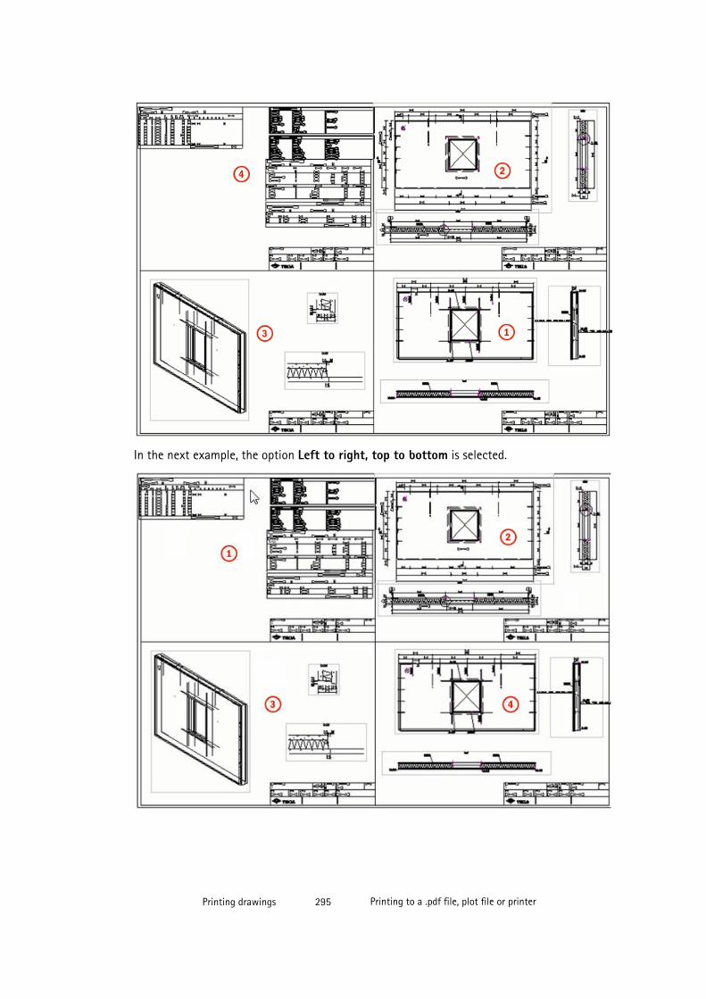
In the next example, the option Left to right, top to bottom is selected.
Printing drawings 295 Printing to a .pdf file, plot file or printer

See also
Printing drawings on page 291
Customizing print output file names on page 297
Printing configuration files on page 296
6.2 Printing settings and search orderTekla Structures printing settings in the Print Drawings dialog box are stored in two files:<user>_ PdfPrintOptions.xml and PdfPrintOptions.xml. When you opena new model, the PdfPrintOptions.xml file is loaded. The changes that you make inprinting settings are automatically saved in <user>_ PdfPrintOptions.xml, andsettings in this file are loaded when you re-open the model.
When you open the Print Drawings dialog box, change printing settings, and re-open thedialog box, the following happens:
• If the model is new, Tekla Structures searches for the printing settings from thePdfPrintOptions.xml file in the XS_PROJECT, XS_FIRM, and XS_SYSTEMfolders, in that order, and uses the settings in the first PdfPrintOptions.xml thatit finds. This makes it possible for organizations to set up the default dialog box settingsincluding the line color thicknesses. If Tekla Structures does not find a file, it usesinternal hard coded defaults.
• When you close the dialog box, Tekla Structures saves the dialog box settingsautomatically to <model>\attributes\<user>_ PdfPrintOptions.xml.
• When you re-open the Print Drawings dialog box in the same model, Tekla Structureswill again search for the printing settings file, and first find <user>_PdfPrintOptions.xml in the <model>\attributes folder, because that isthe first one in the search sequence.
• At the model level, Tekla Structures looks for and saves to <user>_PdfPrintOptions.xml, but in all other locations it looks forPdfPrintOptions.xml. This ensures with shared models in multiuser mode or inTekla model staring that the users dialog settings are kept separate from other users ofthe model.
See also
Printing drawings on page 291
6.3 Printing configuration filesIn printing, two configuration files are used related to paper sizes and drawing sizes:PaperSizesForDrawings.dat and DrawingSizes.dat.
Printing drawings 296 Printing settings and search order

• PaperSizesForDrawings.dat defines a list of paper size names allowed to beused, and their dimensions.
• DrawingSizes.dat provides a list of properties that should be set up to match thedrawing sizes configured in the Tekla Structures drawing layout definitions. It is used tolink those drawings to the paper size name that each drawing was set up for, andprovides information about the drawing sizes and the margins around them.
The PaperSizesForDrawings.dat file is by default located in the ..\ProgramData\Tekla Structures\<version>\environments\common\system folder. The DrawingSizes.dat file is located in the \system folder in thecommon, UK, Germany, US imperial and US metric environments. Default values are providedin the files installed with the printing functionality and should be appropriate in most cases.However, the optimum values are dependent on the details of the existing drawing layoutdefinitions. If the printed area of the drawing needs to be moved, or if inappropriate papersizes are being selected, full instructions about how to make adjustments are detailed inthese two files.
Make copies of the original configuration files if you want to modify the settings, and placethe copies in appropriate folders. This means that you may have several copies of theconfiguration files on your computer. When needed, these files are searched for and the firstone found is used in the following search order:
• model folder
• project folder as defined by the XS_PROJECT advanced option
• firm folder as defined by the XS_FIRM advanced option
• folders as defined by the XS_SYSTEM advanced option
If no files are found default values will be used.
TIP When making copies of the files, keep them first in a test model folder. Validate theresults before using them through the project, firm or environment folders. Also, keepbackup copies of the configuration files in a safe location as re-installing later versionsof Tekla Structures may overwrite your own settings.
See also
Printing drawings on page 291
Printing to a .pdf file, plot file or printer on page 292
6.4 Customizing print output file names
You can affect the way Tekla Structures automatically names the .pdf files and plot files byusing certain drawing-type-specific advanced options.
To customize the print output file names:
1. In Tekla Structures, go to Tools --> Options --> Advanced Options --> Printing .
Printing drawings 297 Customizing print output file names
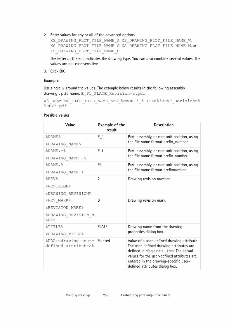
2. Enter values for any or all of the advanced options XS_DRAWING_PLOT_FILE_NAME_A, XS_DRAWING_PLOT_FILE_NAME_W, XS_DRAWING_PLOT_FILE_NAME_G, XS_DRAWING_PLOT_FILE_NAME_M, or XS_DRAWING_PLOT_FILE_NAME_C.
The letter at the end indicates the drawing type. You can also combine several values. Thevalues are not case sensitive.
3. Click OK.
Example
Use single % around the values. The example below results in the following assemblydrawing .pdf name: E_P1_PLATE_Revision=2.pdf:
XS_DRAWING_PLOT_FILE_NAME_A=E_%NAME.%_%TITLE%%REV?_Revision=%%REV%.pdf
Possible values
Value Example of theresult
Description
%NAME%%DRAWING_NAME%
P_1 Part, assembly, or cast unit position, usingthe file name format prefix_number.
%NAME.-%%DRAWING_NAME.-%
P-1 Part, assembly, or cast unit position, usingthe file name format prefix-number.
%NAME.%%DRAWING_NAME.%
P1 Part, assembly, or cast unit position, usingthe file name format prefixnumber.
%REV%%REVISION%%DRAWING_REVISION%
2 Drawing revision number.
%REV_MARK%%REVISION_MARK%%DRAWING_REVISION_MARK%
B Drawing revision mark.
%TITLE%%DRAWING_TITLE%
PLATE Drawing name from the drawingproperties dialog box.
%UDA:<drawing user-defined attribute>%
Painted Value of a user-defined drawing attribute.The user-defined drawing attributes aredefined in objects.inp. The actualvalues for the user-defined attributes areentered in the drawing-specific user-defined attributes dialog box.
Printing drawings 298 Customizing print output file names
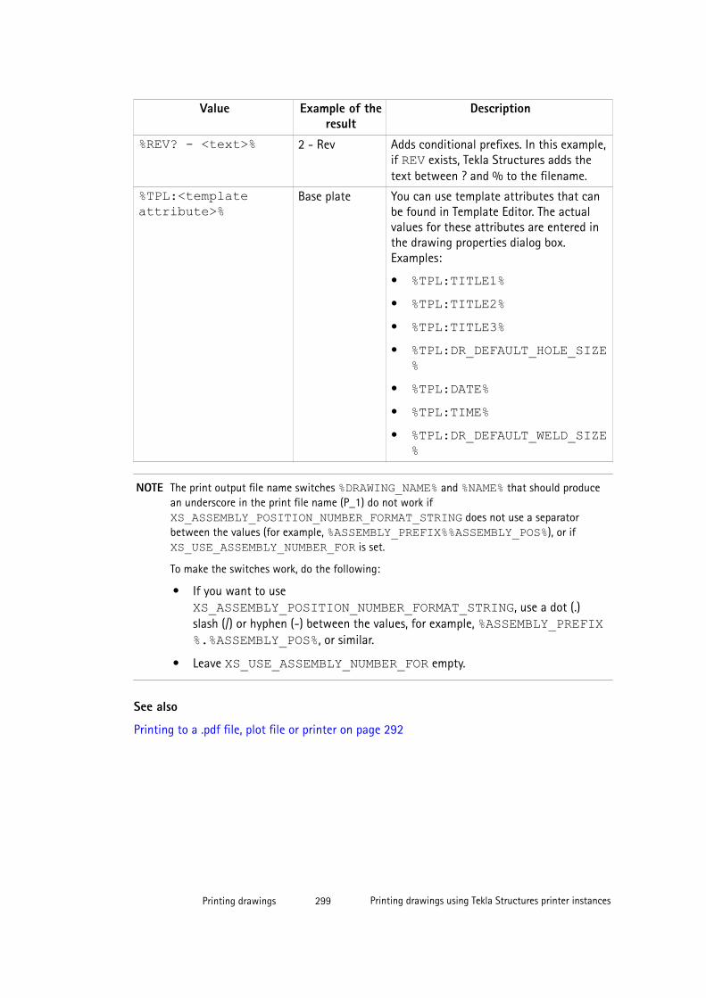
Value Example of theresult
Description
%REV? - <text>% 2 - Rev Adds conditional prefixes. In this example,if REV exists, Tekla Structures adds thetext between ? and % to the filename.
%TPL:<templateattribute>%
Base plate You can use template attributes that canbe found in Template Editor. The actualvalues for these attributes are entered inthe drawing properties dialog box.Examples:
• %TPL:TITLE1%• %TPL:TITLE2%• %TPL:TITLE3%• %TPL:DR_DEFAULT_HOLE_SIZE
%• %TPL:DATE%• %TPL:TIME%• %TPL:DR_DEFAULT_WELD_SIZE
%
NOTE The print output file name switches %DRAWING_NAME% and %NAME% that should producean underscore in the print file name (P_1) do not work if XS_ASSEMBLY_POSITION_NUMBER_FORMAT_STRING does not use a separatorbetween the values (for example, %ASSEMBLY_PREFIX%%ASSEMBLY_POS%), or if XS_USE_ASSEMBLY_NUMBER_FOR is set.
To make the switches work, do the following:
• If you want to use XS_ASSEMBLY_POSITION_NUMBER_FORMAT_STRING, use a dot (.)slash (/) or hyphen (-) between the values, for example, %ASSEMBLY_PREFIX%.%ASSEMBLY_POS%, or similar.
• Leave XS_USE_ASSEMBLY_NUMBER_FOR empty.
See also
Printing to a .pdf file, plot file or printer on page 292
Printing drawings 299 Printing drawings using Tekla Structures printer instances
6.5 Printing drawings using Tekla Structures printer instances
You can also use Tekla Structures own printer instances for printing drawings. To do this, youneed to set XS_USE_OLD_PLOT_DIALOG to TRUE. Using this advanced option takes thePrinter Catalog dialog box in use, and requires printer instances to be set in Tekla Structures.
Setting up printers in the Microsoft Windows environment is not covered in thisdocumentation. It is assumed that printers are set up and tested in your environment. Forfurther information about on setting up printers, contact your system administrator.
Click the links below to find out more:
• Printing single drawings on page 300
• Printing multiple drawings with different sizes in one go on page 303
• Creating PDF files on page 304
• Printing to file on page 304
• Printing to multiple sheets on page 308
• Adding frames and foldmarks in drawings on page 309
• Setting up printer instances in Printer Catalog on page 312
• Printing settings in Print Drawings dialog box on page 317
• Printing tips on page 318
Printing single drawings
There are many ways you can start printing single drawings: you can use menu commands,icons, and pop-up menu commands.
Before you print the drawing, check that the printer instance settings are correct and thelayout contains the correct drawing size settings.
To print single drawings using menu commands in an open drawing:
1. In the drawing, click Drawing File --> Print Drawings... .
2. In the Print Drawings dialog box, select the printer instance you want to use.
3. If needed, modify the printing settings and add frames and foldmarks in the printout.
4. Click Print.
TIP Shortcut for opening the Print Drawings dialog box: Shift+P.
See also
Adding frames and foldmarks in drawings on page 309
Printing drawings using Tekla Structures printer instances on page 299
Printing settings in Print Drawings dialog box on page 317
Printing drawings 300 Printing drawings using Tekla Structures printer instances
Setting up printer instances in Printer Catalog on page 312
Example: Printing on A4 in landscape on page 301
Example: Printing on A3 in portrait on page 301
Example: Printing on A4 in landscape
This example describes how you can print on A4 paper in landscape style in black and white.
NOTE In this example, it is assumed that the print area h*b is defined h being along thelonger side of the paper and b being along the shorter side of the paper. When usingsome other printer driver you might have to change h*b values if you find out thatthe printer driver uses h along the short side of the paper.
To print on A4 in landscape in black and white when a drawing is open:
1. In drawing properties dialog box, click Layout.
2. Set Size definition mode to Specified size and set Drawing size to 287 * 200.
You can also use Autosize. Then you need to make sure that you have definedappropriate Fixed sizes or Calculated sizes.
3. Click Modify and OK.
4. Select Drawing File --> Print Drawings... .
5. In the Print Drawings dialog box, click the printer instance you want to use.
6. Click Add/Edit and check that the printer settings are correct:
• Paper size: A4 210 x 297 mm
• Print area h*b: 287 x 200
• Color: Black/white
7. Click Update.
8. Click OK.
9. Set Scaling to Scale and enter 1.
In this case also Scaling setting Auto would produce a similar printout because drawingsize and h*b are the same.
10. Set Orientation to Landscape (or Auto).
11. Set Print area to Entire Drawing.
12. Click Print.
See also
Printing drawings using Tekla Structures printer instances on page 299
Printing drawings 301 Printing drawings using Tekla Structures printer instances
Example: Printing on A3 in portrait
This example describes how you can print on A3 paper in portrait style in black and white.
You can print from the Drawing List or when a drawing is open.
To print on A3 in portrait in black and white when a drawing is open:
1. In drawing properties dialog box, click Layout.
2. Set Size definition mode to Specified size and set Drawing size to 287 * 410.
You can also use Autosize. Then you need to make sure that you have definedappropriate Fixed sizes or Calculated sizes.
3. Click Modify and OK.
4. Select Drawing File --> Print Drawings... .
5. In the Print Drawings dialog box, click the printer instance you want to use.
6. Click Add/Edit and check that the printer settings are correct:
• Paper size: A3 297 x 420 mm.
• Print area h*b: 410 x 287
• Color: Black/white
7. Click Update.
8. Click OK.
9. Set Scaling to Scale and enter 1.
10. Set Orientation to Portrait (or Auto).
11. Set Print area to Entire Drawing.
12. Click Print.
See also
Printing drawings using Tekla Structures printer instances on page 299
Example: Printing A3 drawing on A4 paper
This example describes how you can print an A3 drawing on A4 paper. This is useful, forexample, when you need draft drawings that do not have to show the correct scale.
To print an A3 drawing on A4:
1. Open the A3 drawing.
2. Select Drawing File --> Print Drawings... .
3. In the Print Drawings dialog box, click the printer instance that you want to use.
Printing drawings 302 Printing drawings using Tekla Structures printer instances
4. Click Add/Edit, click the printer instance that you are going to use and ensure that itprints to A4 paper.
Also ensure that the Print area h*b value takes into account the printer hard margins. Inthis case, the Print area h*b could be 287*200.
5. If you changed any settings, click Update and OK.
If you did not change any settings in the Printer Catalog, click OK to return to the PrintDrawings dialog box.
6. Set Scaling to Auto.
When you use Auto, and the drawing is bigger than the paper, the drawing is scaleddown to fit the paper.
7. Click Print.
See also
Printing single drawings on page 300
Printing multiple drawings with different sizes in one go
You can print multiple drawings from the Drawing List. You can print drawings of differentsizes at the same time.
To print multiple drawings even of different sizes:
1. In the Drawing List, select the drawings you want to print.
2. Click the Print drawings button on the toolbar.
3. In the Print Drawings dialog box, indicate the printers you want to use.
To select several printers, hold down Ctrl and select the printers.
When you select drawings of several sizes and several printers, Tekla Structures sendseach drawing to the printer that is using the smallest paper size on which the drawingwill fit. For example, if you have two printers selected, one A4 and one A3, TeklaStructures will send A4 drawings to the A4 printer and A3 to the A3 printer.
4. Set Scale to 1.
This makes it possible for Tekla Structures to select and use the printer instance that isusing the correct paper size.
5. If necessary, modify other printing settings and add frames and foldmarks in the printout.
6. Click Print.
See also
Adding frames and foldmarks in drawings on page 309
Printing drawings 303 Printing drawings using Tekla Structures printer instances
Printing drawings using Tekla Structures printer instances on page 299
Printing single drawings on page 300
Creating PDF files
You can use any standard PDF printer to create PDF files in Tekla Structures, such aspdfFactory, Win2PDF or Adobe Acrobat.
Before you start creating PDF files using Adobe Acrobat, ensure that you have Adobe Acrobatand Adobe Distiller installed and configured with the Adobe Postscript Printer Driver set up toprint to file. Consult your Adobe documentation for more information.
Also ensure that you have an Adobe postscript printer instance in the Tekla Structures printercatalog.
To create PDF files:
1. In the Drawing List, select the drawings of which you want to make PDF files.
2. Click the Print drawings button .
3. In the Print Drawings dialog box, select the PDF printer instances you want to use.
If you select several printer instances, Tekla Structures sends each drawing to the printerinstance that is using the smallest paper size on which the drawing will fit. For example,if you have two printer instances selected, one A4 and one A3, Tekla Structures will sendA4 drawings to the A4 printer and A3 to the A3 printer.
4. If needed, modify the printing settings and add frames and foldmarks in the PDF.
5. Click Print.
Tekla Structures creates the PDF files and saves them in the folder that you specifiedwhen you defined the printer instance. The file will have the name shown in the DrawingList with the extension ps.
Limitations
Do not use the Print to file option when you create PDF files.
See also
Printing settings in Print Drawings dialog box on page 317
Adding an Adobe postscript printer instance on page 314
Adding frames and foldmarks in drawings on page 309
Printing drawings using Tekla Structures printer instances on page 299
Printing drawings 304 Printing drawings using Tekla Structures printer instances
Printing to file
Before you start, make sure you have a printer instance set up to print to file.
To print to a file:
1. In the Drawing List, select all the drawings that you want to print.
2. Click the Print drawings button on the toolbar.
3. Click a printer instance that is set up to print to file.
4. Select the Print to file check box.
Specify the folder. You can use the folder specified during printer instance setup or clickBrowse... to locate the destination folder in the Browse For Folder dialog box.
If you do not enter a folder, Tekla Structures creates the files in the current model folderor in the folder defined by the advanced option XS_DRAWING_PLOT_FILE_DIRECTORY.
5. If needed, modify other printing settings and add frames and foldmarks in the printout.
6. Click Print.
Tekla Structures prints the selected drawings to files in the specified folder using the drawingnames.
See also
Printing settings in Print Drawings dialog box on page 317
Printing drawings using Tekla Structures printer instances on page 299
Adding a print-to-file instance on page 313
Customizing print file names
By default, Tekla Structures uses the drawing names as print file names. You can customizethese file names using an advanced option indicating the drawing type, and enteringswitches defining the format of the print file name as a value.
To customize the filenames:
1. Go to Tools --> Options --> Advanced Options... --> Printing .
2. Enter switches for the advanced options XS_DRAWING_PLOT_FILE_NAME_A, XS_DRAWING_PLOT_FILE_NAME_W, XS_DRAWING_PLOT_FILE_NAME_G, XS_DRAWING_PLOT_FILE_NAME_M, and XS_DRAWING_PLOT_FILE_NAME_C
You can also combine several switches. The switches are not case sensitive.
3. Click OK.
Printing drawings 305 Printing drawings using Tekla Structures printer instances
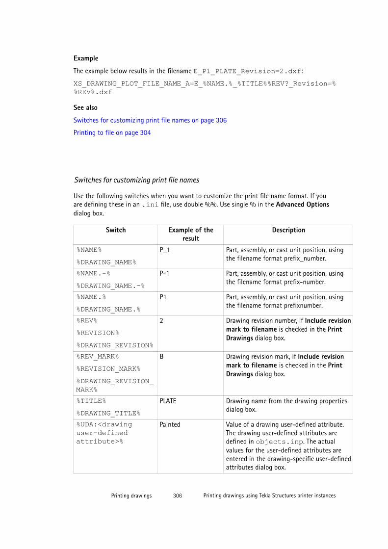
Example
The example below results in the filename E_P1_PLATE_Revision=2.dxf:
XS_DRAWING_PLOT_FILE_NAME_A=E_%NAME.%_%TITLE%%REV?_Revision=%%REV%.dxf
See also
Switches for customizing print file names on page 306
Printing to file on page 304
Switches for customizing print file names
Use the following switches when you want to customize the print file name format. If youare defining these in an .ini file, use double %%. Use single % in the Advanced Optionsdialog box.
Switch Example of theresult
Description
%NAME%%DRAWING_NAME%
P_1 Part, assembly, or cast unit position, usingthe filename format prefix_number.
%NAME.-%%DRAWING_NAME.-%
P-1 Part, assembly, or cast unit position, usingthe filename format prefix-number.
%NAME.%%DRAWING_NAME.%
P1 Part, assembly, or cast unit position, usingthe filename format prefixnumber.
%REV%%REVISION%%DRAWING_REVISION%
2 Drawing revision number, if Include revisionmark to filename is checked in the PrintDrawings dialog box.
%REV_MARK%%REVISION_MARK%%DRAWING_REVISION_MARK%
B Drawing revision mark, if Include revisionmark to filename is checked in the PrintDrawings dialog box.
%TITLE%%DRAWING_TITLE%
PLATE Drawing name from the drawing propertiesdialog box.
%UDA:<drawinguser-definedattribute>%
Painted Value of a drawing user-defined attribute.The drawing user-defined attributes aredefined in objects.inp. The actualvalues for the user-defined attributes areentered in the drawing-specific user-definedattributes dialog box.
Printing drawings 306 Printing drawings using Tekla Structures printer instances
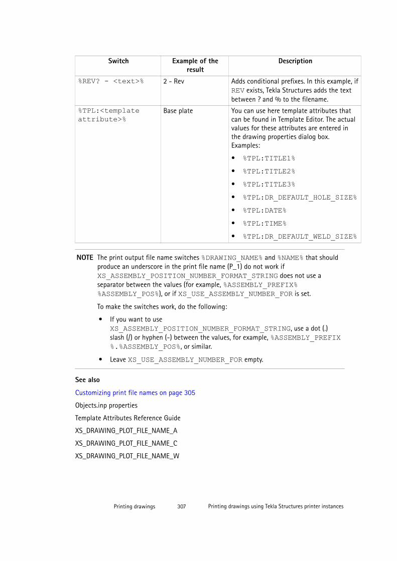
Switch Example of theresult
Description
%REV? - <text>% 2 - Rev Adds conditional prefixes. In this example, if REV exists, Tekla Structures adds the textbetween ? and % to the filename.
%TPL:<templateattribute>%
Base plate You can use here template attributes thatcan be found in Template Editor. The actualvalues for these attributes are entered inthe drawing properties dialog box.Examples:
• %TPL:TITLE1%• %TPL:TITLE2%• %TPL:TITLE3%• %TPL:DR_DEFAULT_HOLE_SIZE%• %TPL:DATE%• %TPL:TIME%• %TPL:DR_DEFAULT_WELD_SIZE%
NOTE The print output file name switches %DRAWING_NAME% and %NAME% that shouldproduce an underscore in the print file name (P_1) do not work if XS_ASSEMBLY_POSITION_NUMBER_FORMAT_STRING does not use aseparator between the values (for example, %ASSEMBLY_PREFIX%%ASSEMBLY_POS%), or if XS_USE_ASSEMBLY_NUMBER_FOR is set.
To make the switches work, do the following:
• If you want to use XS_ASSEMBLY_POSITION_NUMBER_FORMAT_STRING, use a dot (.)slash (/) or hyphen (-) between the values, for example, %ASSEMBLY_PREFIX%.%ASSEMBLY_POS%, or similar.
• Leave XS_USE_ASSEMBLY_NUMBER_FOR empty.
See also
Customizing print file names on page 305
Objects.inp properties
Template Attributes Reference Guide
XS_DRAWING_PLOT_FILE_NAME_A
XS_DRAWING_PLOT_FILE_NAME_C
XS_DRAWING_PLOT_FILE_NAME_W
Printing drawings 307 Printing drawings using Tekla Structures printer instances
XS_DRAWING_PLOT_FILE_NAME_M
XS_DRAWING_PLOT_FILE_NAME_G
Printing to multiple sheets
Before printing to multiple sheets, make sure that the layout of the drawing supportsprinting on several smaller sheets. Remember that Tekla Structures automatically adds a 5mm margin to the printouts.
Also ensure that you have set up the printer instance correctly for printing to multiple sheets.
To print on several smaller sheets:
1. In the drawing, click Drawing File --> Print Drawings... .
2. In the Print Drawings dialog box, select the printer instance you want to use.
3. Select the Print on multiple sheets option.
4. In Scaling, set Scale = 1. This preserves the scale. The number of sheets is rounded up.
Do not use Auto when you print to multiple sheets.
Tekla Structures calculates the required amount of sheets needed to print the drawing.
5. If needed, modify other printing settings and add frames and foldmarks in the printout.
If you set Orientation to Auto, Tekla Structures selects an orientation that results in thesmallest number of printed sheets.
Tekla Structures prints the drawing to multiple sheets so that it prints the lower right cornerthe first, and the upper left corner the last (see the numbered sheets in the example below).
If you want to have drawing frames and/or the title blocks for each smaller size sheet, youneed to use proper table layout as shown in the example below.
Printing drawings 308 Printing drawings using Tekla Structures printer instances

TIP Use the advanced option XS_PRINT_MULTISHEET_BORDER to set borders that are left outfrom the smaller sheets.
See also
Printing settings in Print Drawings dialog box on page 317
Printing drawings using Tekla Structures printer instances on page 299
Adding frames and foldmarks in drawingsYou can have a frame around drawing contents, or two drawing frames inside each other.You can add default Tekla Structures frames around the drawing contents, or use DWG/DXFfiles in the table layouts as drawing frames.
You can create foldmarks as guides for folding printed drawings. They are small lines betweenand perpendicular to the drawing frames.
Printing drawings 309 Printing drawings using Tekla Structures printer instances
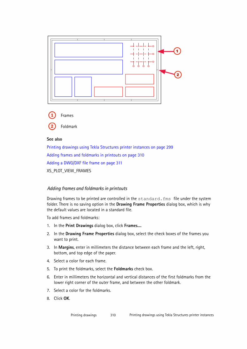
Frames
Foldmark
See also
Printing drawings using Tekla Structures printer instances on page 299
Adding frames and foldmarks in printouts on page 310
Adding a DWG/DXF file frame on page 311
XS_PLOT_VIEW_FRAMES
Adding frames and foldmarks in printouts
Drawing frames to be printed are controlled in the standard.fms file under the systemfolder. There is no saving option in the Drawing Frame Properties dialog box, which is whythe default values are located in a standard file.
To add frames and foldmarks:
1. In the Print Drawings dialog box, click Frames....
2. In the Drawing Frame Properties dialog box, select the check boxes of the frames youwant to print.
3. In Margins, enter in millimeters the distance between each frame and the left, right,bottom, and top edge of the paper.
4. Select a color for each frame.
5. To print the foldmarks, select the Foldmarks check box.
6. Enter in millimeters the horizontal and vertical distances of the first foldmarks from thelower right corner of the outer frame, and between the other foldmark.
7. Select a color for the foldmarks.
8. Click OK.
Printing drawings 310 Printing drawings using Tekla Structures printer instances
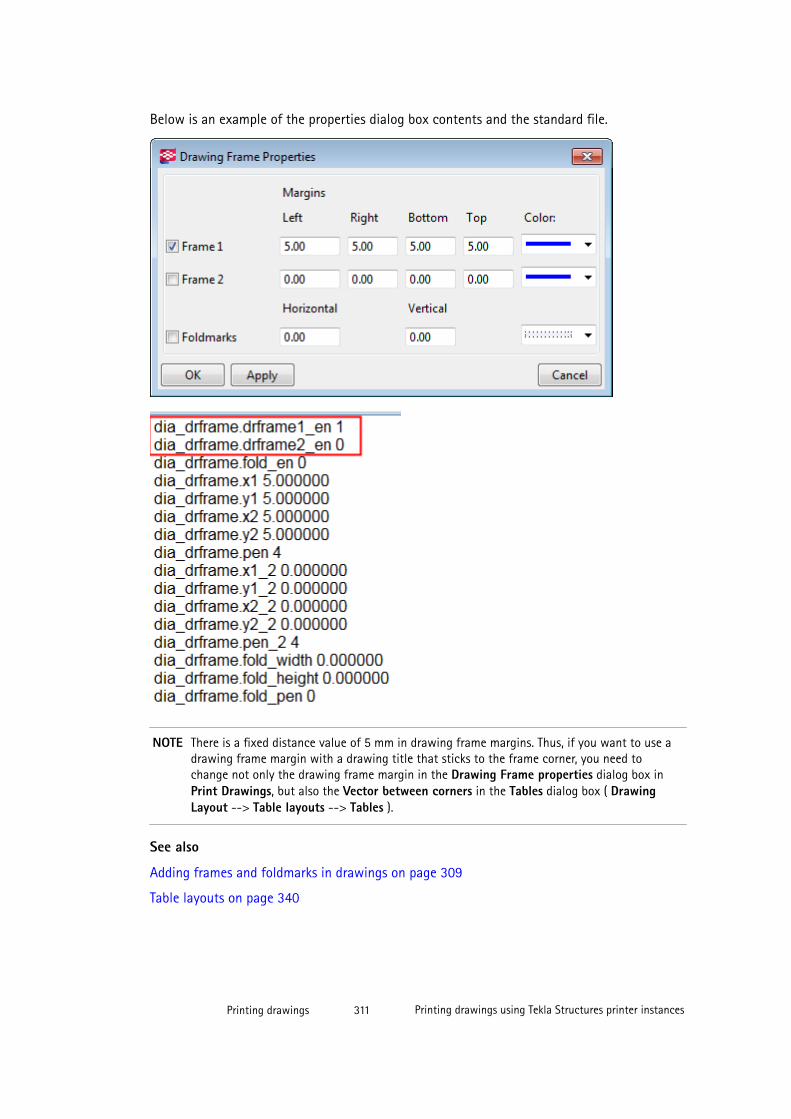
Below is an example of the properties dialog box contents and the standard file.
NOTE There is a fixed distance value of 5 mm in drawing frame margins. Thus, if you want to use adrawing frame margin with a drawing title that sticks to the frame corner, you need tochange not only the drawing frame margin in the Drawing Frame properties dialog box inPrint Drawings, but also the Vector between corners in the Tables dialog box ( DrawingLayout --> Table layouts --> Tables ).
See also
Adding frames and foldmarks in drawings on page 309
Table layouts on page 340
Printing drawings 311 Printing drawings using Tekla Structures printer instances
Adding a DWG/DXF file frame
DWG/DXF files can be used as drawing frames. You can do this by adding the DWG/DXF file inthe table layout of the drawing.
1. Click Drawings & Reports --> Drawing Settings --> Drawing Layout... .
2. Select a layout and click Table layout....
3. Select a table layout and click Tables....
4. Double-click DWG/DXF in the Available tables list.
5. Select the file and click OK.
6. Click Update.
7. Set the Scale.
8. Select Transparent.
9. Click OK.
See also
Adding frames and foldmarks in drawings on page 309
Table layouts on page 340
Setting up printer instances in Printer CatalogTekla Structures uses Microsoft Windows printer drivers to write the printed data directly toa printer, print file or PDF file.
There are two stages in setting up printer instances in Tekla Structures:
• First, you need to add a printer instance in the Printer Catalog. By default, severalprinter instances are already defined.
• Next, you need connect the printer instances to printer drivers and adjust the printerinstance settings. You can also connect one printer driver to several printer instances, forexample, to print in different sizes on the same printer.
See also
Adding a printer instance on page 312
Adding a print-to-file instance on page 313
Adding an Adobe postscript printer instance on page 314
Defining paper size on page 315
Defining print area h*b on page 316
Colors and line weights in printing on page 316
Printing drawings 312 Printing drawings using Tekla Structures printer instances

Adding a printer instance
To add a printer instance in Tekla Structures Printer Catalog:
1. In the model, click File --> Print --> Printer Catalog....
2. In the Printer Catalog dialog box, click an existing printer instance that has similarsettings to the one you want to add.
3. Enter a name for the new printer instance in the box under the Printer instances list.
4. Click Add.
5. Click Browse... to access the Select Printer dialog box, which shows a list of MicrosoftWindows printer drivers currently configured in your system.
6. Click a printer driver and then OK.
7. Select the paper size.
8. Enter the print area in Print area h*b (height and width).
9. If necessary, use Offset for print origin to move the drawing print origin.
10. Select Black/white, Gray Scale or Color.
If you select Color, Tekla Structures prints lines with the colors defined in the drawingproperties.
11. Click Color table to map pen size to the on-screen line color. The background color is notprinted.
12. Click Update.
13. Click OK.
14. Confirm that you want to save changes to the model folder.
See also
Printing drawings using Tekla Structures printer instances on page 299
Defining paper size on page 315
Defining print area h*b on page 316
Colors and line weights in printing on page 316
Adding a print-to-file instance
To add a print-to-file instance in the Printer Catalog:
1. In Printer Catalog, click Add.
2. Enter a printer instance name for the printer driver, followed immediately (no spaces) by@path\folder\. The folder must already exist. For example, 11X17@d:\small\
Printing drawings 313 Printing drawings using Tekla Structures printer instances
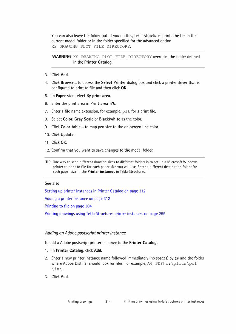
You can also leave the folder out. If you do this, Tekla Structures prints the file in thecurrent model folder or in the folder specified for the advanced option XS_DRAWING_PLOT_FILE_DIRECTORY.
WARNING XS_DRAWING_PLOT_FILE_DIRECTORY overrides the folder definedin the Printer Catalog.
3. Click Add.
4. Click Browse... to access the Select Printer dialog box and click a printer driver that isconfigured to print to file and then click OK.
5. In Paper size, select By print area.
6. Enter the print area in Print area h*b.
7. Enter a file name extension, for example, plt for a print file.
8. Select Color, Gray Scale or Black/white as the color.
9. Click Color table... to map pen size to the on-screen line color.
10. Click Update.
11. Click OK.
12. Confirm that you want to save changes to the model folder.
TIP One way to send different drawing sizes to different folders is to set up a Microsoft Windowsprinter to print to file for each paper size you will use. Enter a different destination folder foreach paper size in the Printer instances in Tekla Structures.
See also
Setting up printer instances in Printer Catalog on page 312
Adding a printer instance on page 312
Printing to file on page 304
Printing drawings using Tekla Structures printer instances on page 299
Adding an Adobe postscript printer instance
To add a Adobe postscript printer instance to the Printer Catalog:
1. In Printer Catalog, click Add.
2. Enter a new printer instance name followed immediately (no spaces) by @ and the folderwhere Adobe Distiller should look for files. For example, A4_PDF@c:\plots\pdf\in\ .
3. Click Add.
Printing drawings 314 Printing drawings using Tekla Structures printer instances
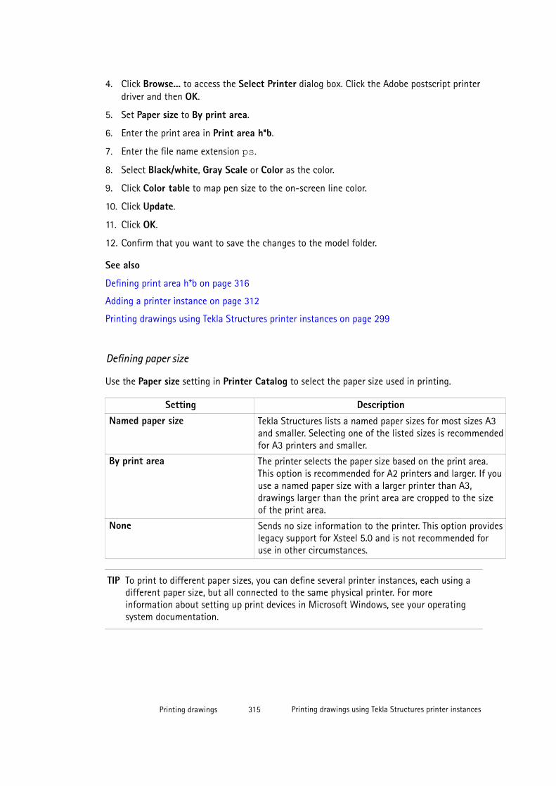
4. Click Browse... to access the Select Printer dialog box. Click the Adobe postscript printerdriver and then OK.
5. Set Paper size to By print area.
6. Enter the print area in Print area h*b.
7. Enter the file name extension ps.
8. Select Black/white, Gray Scale or Color as the color.
9. Click Color table to map pen size to the on-screen line color.
10. Click Update.
11. Click OK.
12. Confirm that you want to save the changes to the model folder.
See also
Defining print area h*b on page 316
Adding a printer instance on page 312
Printing drawings using Tekla Structures printer instances on page 299
Defining paper size
Use the Paper size setting in Printer Catalog to select the paper size used in printing.
Setting DescriptionNamed paper size Tekla Structures lists a named paper sizes for most sizes A3
and smaller. Selecting one of the listed sizes is recommendedfor A3 printers and smaller.
By print area The printer selects the paper size based on the print area.This option is recommended for A2 printers and larger. If youuse a named paper size with a larger printer than A3,drawings larger than the print area are cropped to the sizeof the print area.
None Sends no size information to the printer. This option provideslegacy support for Xsteel 5.0 and is not recommended foruse in other circumstances.
TIP To print to different paper sizes, you can define several printer instances, each using adifferent paper size, but all connected to the same physical printer. For moreinformation about setting up print devices in Microsoft Windows, see your operatingsystem documentation.
Printing drawings 315 Printing drawings using Tekla Structures printer instances
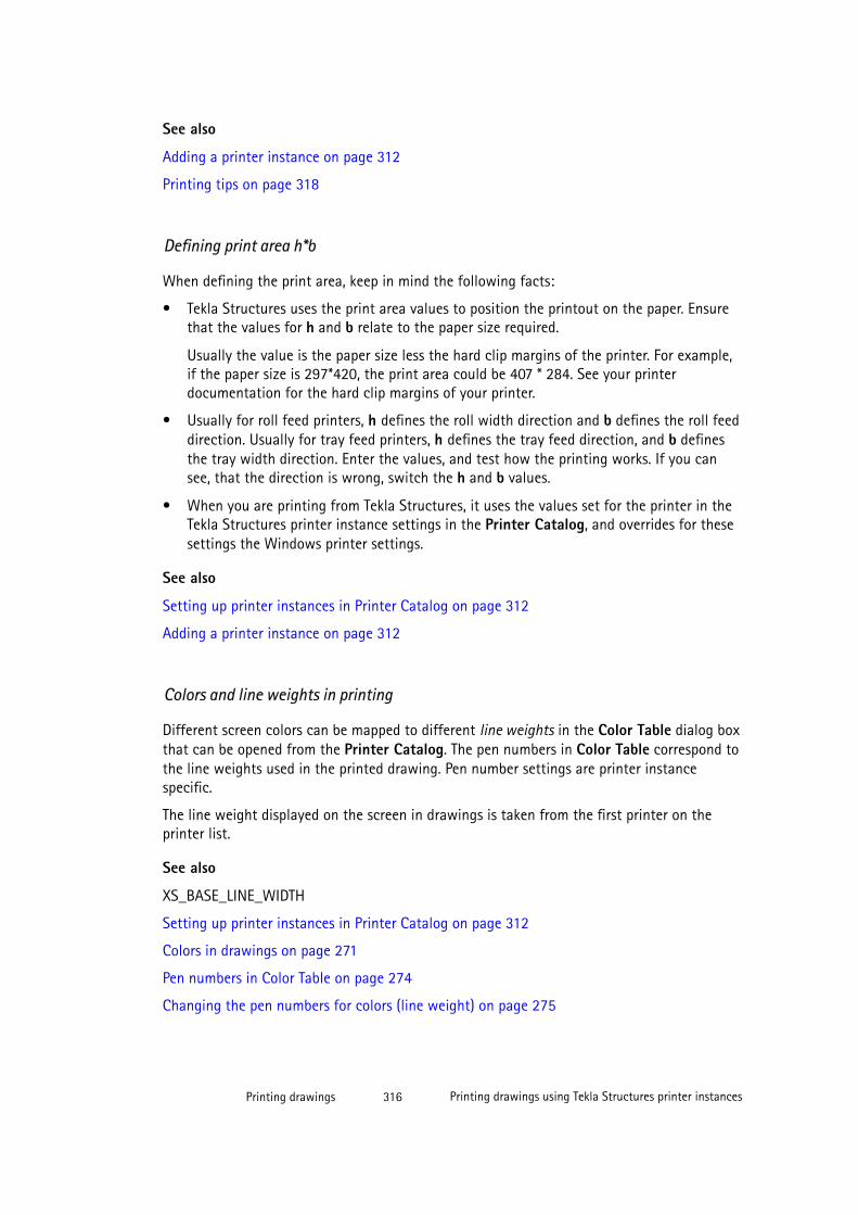
See also
Adding a printer instance on page 312
Printing tips on page 318
Defining print area h*b
When defining the print area, keep in mind the following facts:
• Tekla Structures uses the print area values to position the printout on the paper. Ensurethat the values for h and b relate to the paper size required.
Usually the value is the paper size less the hard clip margins of the printer. For example,if the paper size is 297*420, the print area could be 407 * 284. See your printerdocumentation for the hard clip margins of your printer.
• Usually for roll feed printers, h defines the roll width direction and b defines the roll feeddirection. Usually for tray feed printers, h defines the tray feed direction, and b definesthe tray width direction. Enter the values, and test how the printing works. If you cansee, that the direction is wrong, switch the h and b values.
• When you are printing from Tekla Structures, it uses the values set for the printer in theTekla Structures printer instance settings in the Printer Catalog, and overrides for thesesettings the Windows printer settings.
See also
Setting up printer instances in Printer Catalog on page 312
Adding a printer instance on page 312
Colors and line weights in printing
Different screen colors can be mapped to different line weights in the Color Table dialog boxthat can be opened from the Printer Catalog. The pen numbers in Color Table correspond tothe line weights used in the printed drawing. Pen number settings are printer instancespecific.
The line weight displayed on the screen in drawings is taken from the first printer on theprinter list.
See also
XS_BASE_LINE_WIDTH
Setting up printer instances in Printer Catalog on page 312
Colors in drawings on page 271
Pen numbers in Color Table on page 274
Changing the pen numbers for colors (line weight) on page 275
Printing drawings 316 Printing drawings using Tekla Structures printer instances
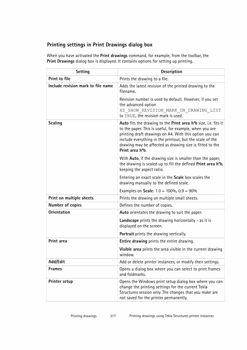
Printing settings in Print Drawings dialog box
When you have activated the Print drawings command, for example, from the toolbar, thePrint Drawings dialog box is displayed. It contains options for setting up printing.
Setting DescriptionPrint to file Prints the drawing to a file.
Include revision mark to file name Adds the latest revision of the printed drawing to thefilename.
Revision number is used by default. However, if you setthe advanced option XS_SHOW_REVISION_MARK_ON_DRAWING_LISTto TRUE, the revision mark is used.
Scaling Auto fits the drawing to the Print area h*b size, i.e. fits itto the paper. This is useful, for example, when you areprinting draft drawings on A4. With this option you caninclude everything in the printout, but the scale of thedrawing may be affected as drawing size is fitted to thePrint area h*b.
With Auto, if the drawing size is smaller than the paper,the drawing is scaled up to fill the defined Print area h*b,keeping the aspect ratio.
Entering an exact scale in the Scale box scales thedrawing manually to the defined scale.
Examples on Scale: 1.0 = 100%, 0.9 = 90%
Print on multiple sheets Prints the drawing on multiple small sheets.
Number of copies Defines the number of copies.
Orientation Auto orientates the drawing to suit the paper.
Landscape prints the drawing horizontally - as it isdisplayed on the screen.
Portrait prints the drawing vertically.
Print area Entire drawing prints the entire drawing.
Visible area prints the area visible in the current drawingwindow.
Add/Edit Add or delete printer instances, or modify their settings.
Frames Opens a dialog box where you can select to print framesand foldmarks.
Printer setup Opens the Windows print setup dialog box where you canchange the printing settings for the current TeklaStructures session only. The changes that you make arenot saved for the printer permanently.
Printing drawings 317 Printing drawings using Tekla Structures printer instances

See also
Printing to multiple sheets on page 308
Printing single drawings on page 300
Printing multiple drawings with different sizes in one go on page 303
Adding frames and foldmarks in drawings on page 309
Setting up printer instances in Printer Catalog on page 312
Defining print area h*b on page 316
Printing drawings using Tekla Structures printer instances on page 299
XS_SHOW_REVISION_MARK_ON_DRAWING_LIST
XS_PLOT_VIEW_FRAMES
Printing tips
Here are some tips that help you print drawings the way you want.
• If you are printing a drawing to a smaller paper, the line weights are scaled accordingly.This means that no lines are drawn too thickly and the drawings are more readable.
• You can force a drawing to use a different size paper: Open the drawing and go toDrawing Properties --> Layout . In Size definition mode, select Specified size. Insertthe required sheet size into Drawing size.
• If a drawing does not fit to the paper or is printed to a wrong location, use the Offset forprint origin option in the Printer Catalog to move the drawing print origin for theselected printer instance.
The advanced options XS_PLOT_ORIGIN_MOVE_X and XS_PLOT_ORIGIN_MOVE_Y move the print origin in the x or y direction for allprinter instances. If you set values for the advanced options, they are used instead of theOffset for print origin value.
• You can disable the print date information to prevent the loss of information whenworking with multi-user models. This is useful in cases where a user modifies drawingswhile another user prints the same drawings. Use the XS_DISABLE_DRAWING_PLOT_DATE to disable the print date.
• You can add several Windows printer drivers for the same physical printer, and define anexact paper size for each printer driver in Windows printer driver printing preferences orprinting defaults. Then in Tekla Structures, you can set printer instances so that youselect the printer driver that matches the desired paper size. See the table at the end.
• If you only have one Windows printer driver for one physical printer, define the largestpaper size you are going to use for that printer driver in Windows printer driver printingpreferences or printing defaults, for example, A0. Then in Tekla Structures, you can usethat one printer driver, and set several printer instances for it, each using the necessarypaper size. See the table below.
Printing drawings 318 Printing drawings using Tekla Structures printer instances
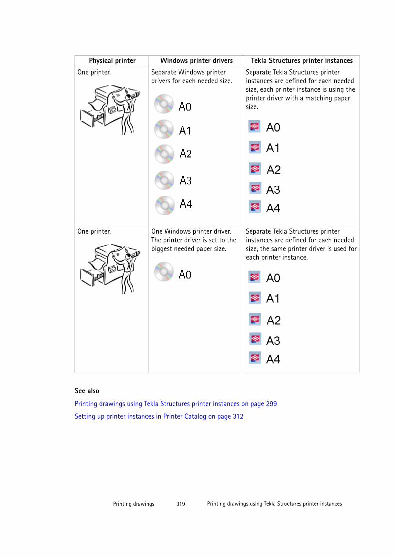
Physical printer Windows printer drivers Tekla Structures printer instances
One printer. Separate Windows printerdrivers for each needed size.
Separate Tekla Structures printerinstances are defined for each neededsize, each printer instance is using theprinter driver with a matching papersize.
One printer. One Windows printer driver.The printer driver is set to thebiggest needed paper size.
Separate Tekla Structures printerinstances are defined for each neededsize, the same printer driver is used foreach printer instance.
See also
Printing drawings using Tekla Structures printer instances on page 299
Setting up printer instances in Printer Catalog on page 312
Printing drawings 319 Printing drawings using Tekla Structures printer instances
7 Modifying drawing settings
Drawing settings tell Tekla Structures what the drawing should look like and what it shouldinclude.
Automatic drawing settings
Automatic drawing settings are settings that are defined through:
• Drawing, view and object properties in various drawing types. The properties are stored inproperties files. Properties can be defined separately for each drawing that you create,but it is advisable to save the most commonly used settings in properties files for futureuse, for example, in Master Drawing Catalog. When creating a new drawing, alwaysstart by loading automatic drawing properties that you think contain the best settings forthe drawing you are creating, and then adjust them as required before creating thedrawing. Properties can be adjusted also after you have created the drawing.
You can open the drawing properties dialog boxes for setting the automatic drawingproperties by selecting Drawings & Reports --> Drawing Settings and then selectingthe drawing type.
• Drawing settings that are defined through various options and advanced options inOptions and Advanced Options.
• Additional settings files, such as rebar_config.inp for setting reinforcement, andhatch_types1.pat for setting hatch patterns.
Single-part, assembly and cast unit drawing properties
These drawings contain two types of automatic properties: drawing-specific and view-specific. Drawing-specific properties apply to the whole drawing: drawing titles, drawinglayout, user-defined properties, protection settings, and some detail and section viewproperties.
Modifying drawing settings 320 Printing drawings using Tekla Structures printer instances
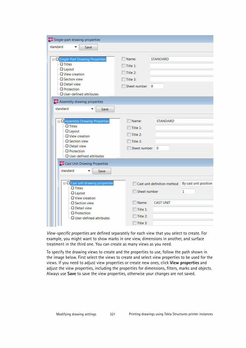
View-specific properties are defined separately for each view that you select to create. Forexample, you might want to show marks in one view, dimensions in another, and surfacetreatment in the third one. You can create as many views as you need.
To specify the drawing views to create and the properties to use, follow the path shown inthe image below. First select the views to create and select view properties to be used for theviews. If you need to adjust view properties or create new ones, click View properties andadjust the view properties, including the properties for dimensions, filters, marks and objects.Always use Save to save the view properties, otherwise your changes are not saved.
Modifying drawing settings 321 Printing drawings using Tekla Structures printer instances
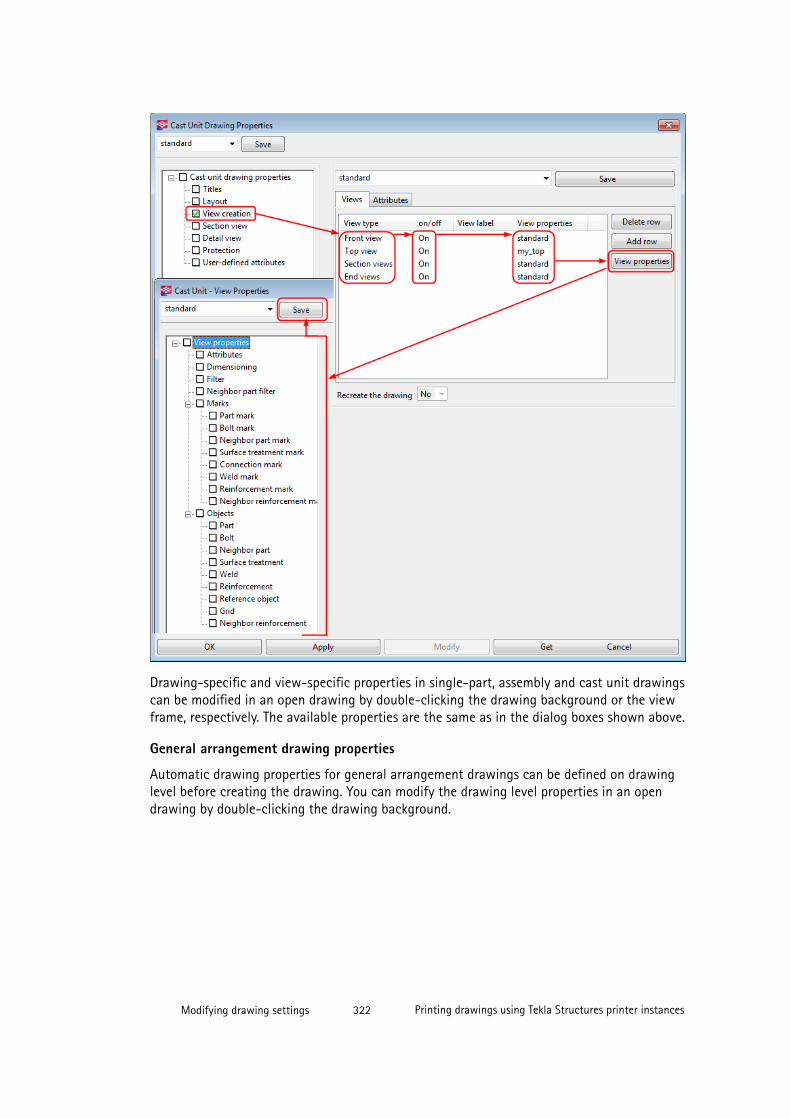
Drawing-specific and view-specific properties in single-part, assembly and cast unit drawingscan be modified in an open drawing by double-clicking the drawing background or the viewframe, respectively. The available properties are the same as in the dialog boxes shown above.
General arrangement drawing properties
Automatic drawing properties for general arrangement drawings can be defined on drawinglevel before creating the drawing. You can modify the drawing level properties in an opendrawing by double-clicking the drawing background.
Modifying drawing settings 322 Printing drawings using Tekla Structures printer instances
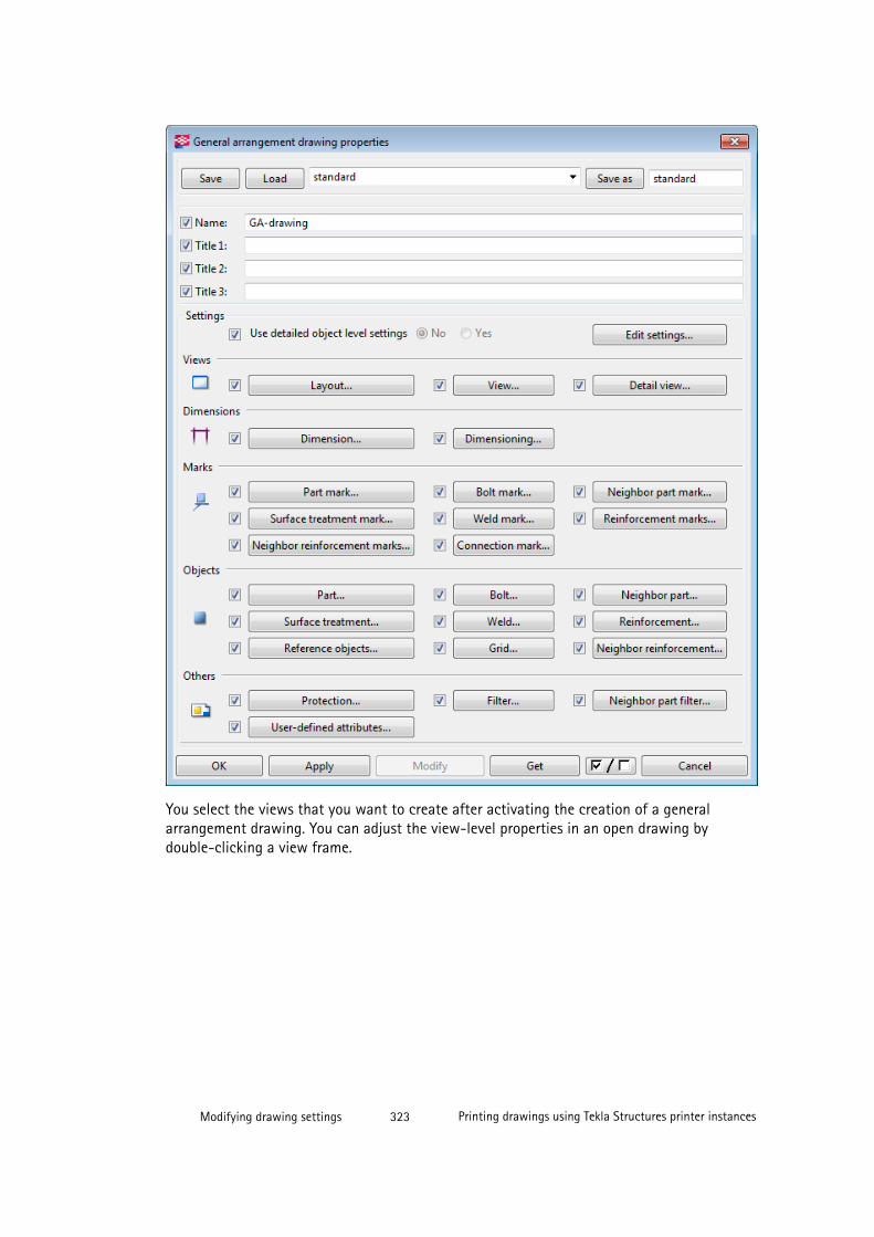
You select the views that you want to create after activating the creation of a generalarrangement drawing. You can adjust the view-level properties in an open drawing bydouble-clicking a view frame.
Modifying drawing settings 323 Printing drawings using Tekla Structures printer instances
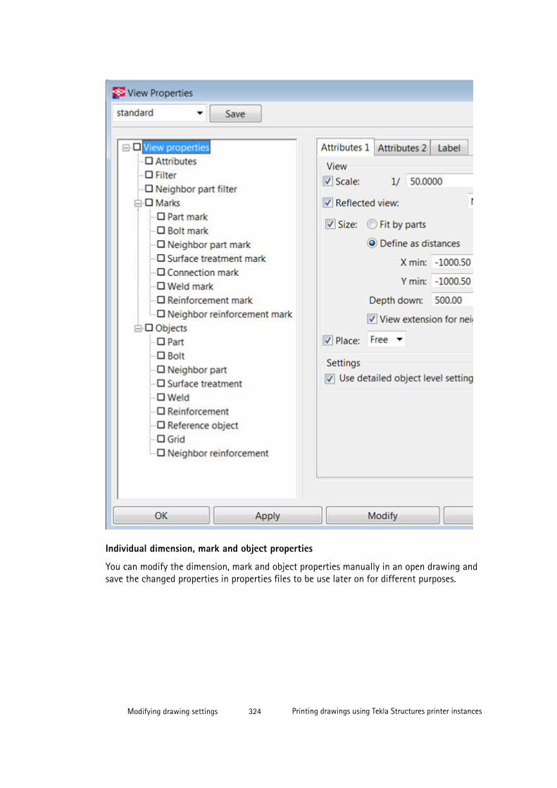
Individual dimension, mark and object properties
You can modify the dimension, mark and object properties manually in an open drawing andsave the changed properties in properties files to be use later on for different purposes.
Modifying drawing settings 324 Printing drawings using Tekla Structures printer instances
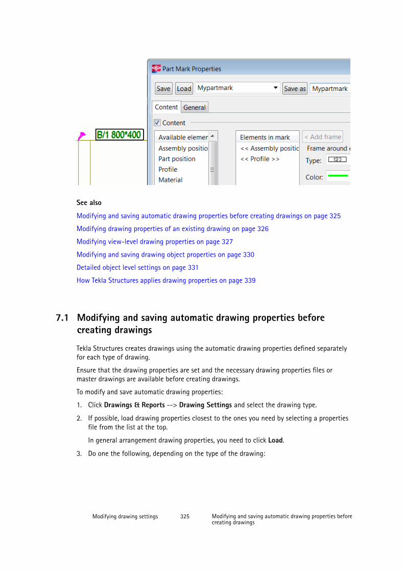
See also
Modifying and saving automatic drawing properties before creating drawings on page 325
Modifying drawing properties of an existing drawing on page 326
Modifying view-level drawing properties on page 327
Modifying and saving drawing object properties on page 330
Detailed object level settings on page 331
How Tekla Structures applies drawing properties on page 339
7.1 Modifying and saving automatic drawing properties beforecreating drawings
Tekla Structures creates drawings using the automatic drawing properties defined separatelyfor each type of drawing.
Ensure that the drawing properties are set and the necessary drawing properties files ormaster drawings are available before creating drawings.
To modify and save automatic drawing properties:
1. Click Drawings & Reports --> Drawing Settings and select the drawing type.
2. If possible, load drawing properties closest to the ones you need by selecting a propertiesfile from the list at the top.
In general arrangement drawing properties, you need to click Load.
3. Do one the following, depending on the type of the drawing:
Modifying drawing settings 325 Modifying and saving automatic drawing properties beforecreating drawings
Single-part, assembly and cast unit drawings:
a. Go through the various properties in the options tree and adjust the values asrequires.
The check boxes next to the options are automatically selected when you changesomething for that particular option.
b. To adjust view-level settings (views, dimensions, marks and objects), click Viewcreation, select the desired view and view properties file and click View properties.
c. Adjust the settings as required.
d. Click Save in View Properties to save the properties in the view properties file, whenyou are done.
e. Click OK in View Properties to return to the drawing properties.
General arrangement drawings:
a. Switch off the all the check boxes by clicking the on/off switch at the bottom
.
b. Select the check boxes for only the options that you wish to change.
c. Go through the various properties in the drawing properties dialog box, and make thenecessary changes.
d. Click OK in each subdialog box where you changed the properties to save thechanges and to return to drawing properties.
4. Click Save to save the properties.
If you want to save the changes in another drawing properties file, enter the new name.
In general arrangement drawing properties, click Save as.
Now you can create a drawing using the modified drawing properties file.
7.2 Modifying drawing properties of an existing drawing
If you are not satisfied with the drawing settings after creating the drawing and checking it,you can modify the automatic drawing properties in the created drawing.
To modify the drawing properties of an existing drawing:
1. Open the drawing
2. Double-click the drawing background.
3. Do one the following, depending on the type of the drawing:
Modifying drawing settings 326 Modifying drawing properties of an existing drawing
Single-part, assembly and cast unit drawings:
a. Go through the various options in the options tree and adjust the values as required.
The check boxes next to the options are automatically selected when you changesomething for that particular option.
b. To adjust view-level settings (views, dimensions, marks and objects), click Viewcreation, select the desired view and view properties file and click View properties.
c. Adjust the view properties as required.
d. Click Save in View Properties to save the properties in the view properties file, whenyou are done.
e. Click OK in View Properties to return to the drawing properties.
General arrangement drawings:
a. Switch all the check boxes off by clicking the on/off switch at thebottom of the dialog box.
b. Select the check boxes for only the options that you wish to change.
c. Go through the various options in the drawing properties dialog box, and make thenecessary changes.
d. Click OK in each subdialog box where you changed the properties to save thechanges and to return to drawing properties.
4. Click Modify.
The drawing is changed according to the changes that you made in the drawingproperties.
NOTE Some of the changes in you make require a drawing recreation. For more information, seeSettings affecting the recreation of drawings on page 328.
TIP You can also modify the properties of several drawings by selecting them from the Drawing List,right-clicking and selecting Properties.
See also
Modifying view-level drawing properties on page 327
Modifying drawing settings 327 Modifying view-level drawing properties
7.3 Modifying view-level drawing properties
Most of the properties that a single-part, assembly and cast unit drawing has are specifiedfor each of the drawing views separately in the automatic drawing properties.
You can modify the view-level drawing properties after you have created the drawing. Thechanges you make apply only to the view that you have selected to modify.
To modify drawing properties on the view level after you have created a drawing:
1. Open the drawing.
2. Double-click a drawing view frame to open the drawing view properties dialog box.
3. The check boxes are off by default. When you touch a property, for example, select anoption, Tekla Structures adds a check mark to the check box next to the option in theoption tree.
4. Make the necessary changes.
5. Click Modify when you are ready with the changes.
The view changes according to the changes that you made in the drawing view properties.
NOTE Some of the changes in you make require a drawing recreation. For more information, seeSettings affecting the recreation of drawings on page 328.
See also
Modifying drawing properties of an existing drawing on page 326
7.4 Settings affecting the recreation of drawings
Changing the following settings requires the drawing to be recreated. The changes will beapplied, and the drawing will be recreated only if and when you click Modify.
In the View creation panel:
• Coordinate system
• Around X
• Around Y
• Around Z
• Undeformed
• Unfolded
• New views added into the Views list.
If at least one of the above mentioned settings is changed, the Recreate the drawing optionis automatically set to Yes and the drawing will be recreated when you click Modify. If you
Modifying drawing settings 328 Settings affecting the recreation of drawings
manually set Recreate the drawing to Yes, the drawing will also be recreated. When Viewcreation settings have changed and drawings will be recreated, you will get a warningmessage.
In the Section view panel:
• Section depth
• Distance for combining cuts
• Left section
• Middle section
• Right section
If at least one of the above mentioned settings is changed, Tekla Structures automaticallyrecreates the drawing without giving a warning message when you click Modify.
If you only want to modify the view properties for one of the created views:
• If the changed properties are saved in the same file for all created views, the only way tomodify the properties for one view is to set Recreate the drawing to Yes.
• If the changed properties are saved in a separate file not used for other created views,and that file is selected for the changed view in the Views list, then drawing will only beupdated on Modify, not recreated.
See also
Preventing automatic drawing updates and recreation on page 329
Updating drawings when the model changes on page 282
7.5 Preventing automatic drawing updates and recreation
Below there are some tips that help you to prevent automatic drawing updates andrecreation:
• Freeze the drawings where you do not want to update all associative objects on top ofthe drawing views. The building objects (parts, bolts, welds, etc.) are always updated infrozen drawings.
• Lock the drawings that you do not want to update.
• If you update a drawing that has not been modified, the drawing is recreated. Drawingsare automatically recreated unless the drawing has been edited and then saved, or thedrawing has been issued using the Issue functionality in the Drawing List. Use theadvanced XS_RECREATE_UNMODIFIED_DRAWINGS to control the recreation ofunmodified drawings.
• To prevent Tekla Structures from automatically updating drawings if the model changes,clear the value field of the advanced option XS_INTELLIGENT_DRAWING_ALLOWED.
Modifying drawing settings 329 Preventing automatic drawing updates and recreation

See also
Settings affecting the recreation of drawings on page 328
XS_INTELLIGENT_DRAWING_ALLOWED
XS_RECREATE_UNMODIFIED_DRAWINGS
Freezing drawings on page 284
7.6 Modifying and saving drawing object properties
You can change the properties of the objects in the drawings such as parts, marks, bolts, andwelds, and save the object properties files for later use.
To modify and save object properties in an open drawing:
1. Open a drawing.
2. Double-click the object that you want to modify.
For example, double-click a part.
3. Change the desired settings in the property dialog box.
For example, go to the Appearance tab and change the part color.
4. In the box next to the Save as button, enter the name for the properties file and clickSave as.
5. Click Cancel to close the object properties dialog box.
Now you have a new object properties file. You can load the properties in this file in otherdrawing objects, in this case, parts. You can also use the object properties files with filters toapply detailed object level settings.
See also
Loading saved drawing object properties in an existing drawing on page 330
Loading saved drawing object properties in an existing drawing
You can change the object properties in an existing drawing by loading saved objectproperties.
To load saved object properties:
1. Open the drawing.
2. Double-click the drawing object you want to change to open the object properties dialogbox. For example, double-click a part.
Modifying drawing settings 330 Modifying and saving drawing object properties
3. Select the desired object properties file from the list next to the Load button and clickLoad.
4. Click Modify.
Tekla Structures changes the drawing object according to the settings in the loaded objectproperties file.
See also
Modifying and saving drawing object properties on page 330
7.7 Detailed object level settingsIn addition to defining automatic drawing mark and object properties, you can also set up aspecial representation for marks and building objects in drawings and use these detailedobject level settings for specific purposes. For example, you may want to define that allcolumns in a specific general arrangement drawing are shown in a specific color, and in allother general arrangement drawings in the default part color.
In general arrangement drawings, you can use detailed object level settings on both drawingand view level. In other drawing types, this setting is view specific.
In order to create detailed objects settings, you need to have:
• A filter that selects the objects that you want to be affected
• Object properties that you want to apply on the objects
See also
Creating detailed object level settings in a general arrangement drawing on page 331
Creating detailed object level settings in a general arrangementdrawing
Before creating the detailed object level settings, create the object properties that you wantto use, and save the properties in a properties file. For example, in part properties, set thepart color to blue and save the properties.
To create detailed object level settings on drawing level in general arrangement drawings:
1. Select Drawings & Reports --> Drawing Settings --> General Arrangement Drawing
2. Click Filter and create a drawing filter that selects the objects that you want to havespecial representation.
Modifying drawing settings 331 Detailed object level settings

For example, create a filter that selects columns.
3. Save the filter by entering a name for it and click Save as.
4. Click Cancel to close the dialog box.
5. In the drawing properties dialog box, click Edit settings.
6. In the Object level settings for drawing/for view dialog box, click Add row and selectthe filters to be used, the drawing object types and the drawing object properties to beused.
By doing this, you are combining the filter, object type, and object property settings intodetailed object level settings.
You can add several rows in detailed object level settings.
7. Give the object level settings a name and save using Save as.
Now you have new detailed object level settings to be applied on a drawing.
See also
Modifying and saving drawing object properties on page 330
Example: Applying detailed object level settings on drawing level on page 332
Example: Applying detailed object level settings on drawing level
In this example, different detailed object level settings will be set up for various types ofbuilding objects, such as beams, columns and braces, in a general arrangement drawing.Before doing this, drawing object properties for beams, columns and braces have been
Modifying drawing settings 332 Detailed object level settings
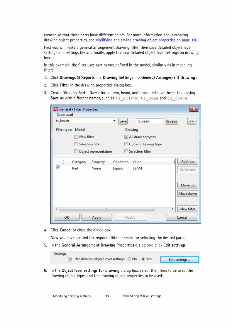
created so that these parts have different colors. For more information about creatingdrawing object properties, see Modifying and saving drawing object properties on page 330.
First you will make a general arrangement drawing filter, then save detailed object levelsettings in a settings file and finally, apply the new detailed object level settings on drawinglevel.
In this example, the filter uses part names defined in the model, similarly as in modelingfilters.
1. Click Drawings & Reports --> Drawing Settings --> General Arrangement Drawing .
2. Click Filter in the drawing properties dialog box.
3. Create filters by Part - Name for column, beam, and brace and save the settings usingSave as with different names, such as ts_column, ts_beam and ts_brace.
4. Click Cancel to close the dialog box.
Now you have created the required filters needed for selecting the desired parts.
5. In the General Arrangement Drawing Properties dialog box, click Edit settings.
6. In the Object level settings for drawing dialog box, select the filters to be used, thedrawing object types and the drawing object properties to be used:
Modifying drawing settings 333 Detailed object level settings
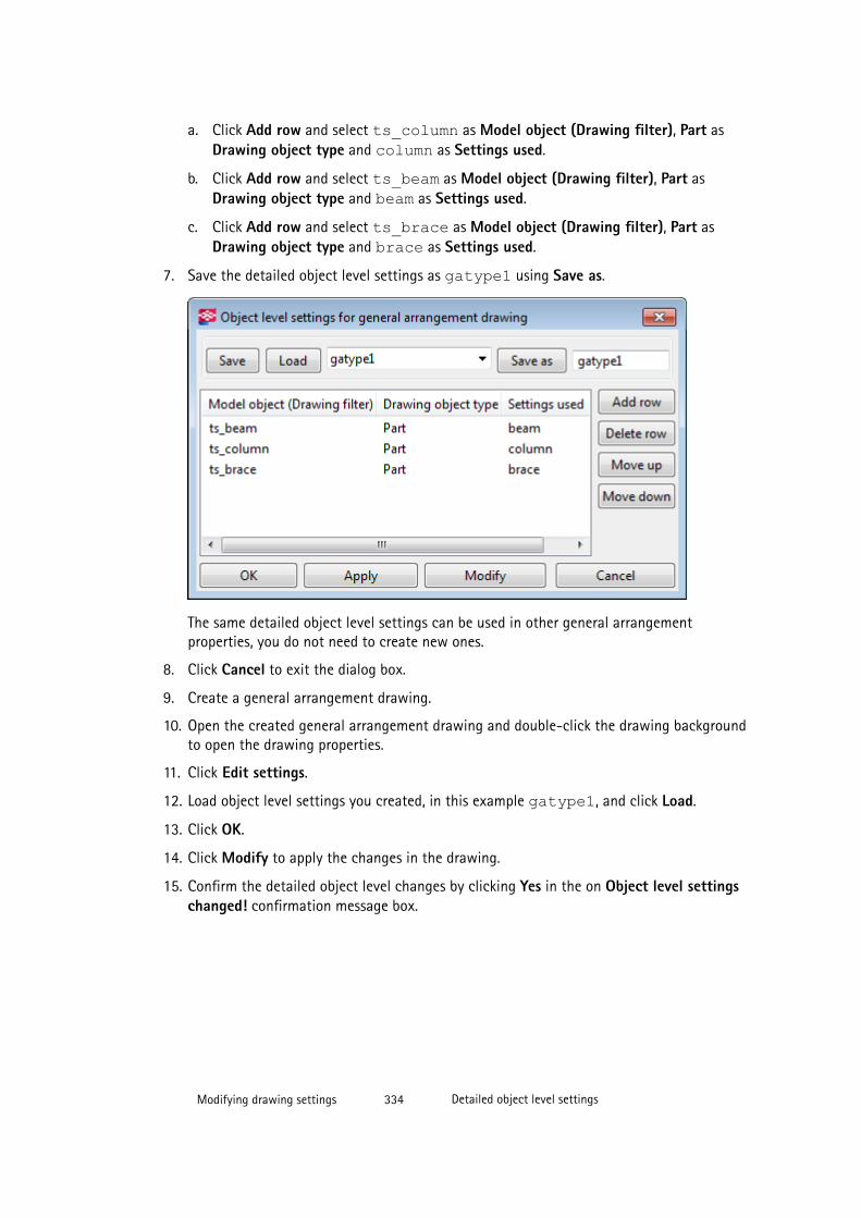
a. Click Add row and select ts_column as Model object (Drawing filter), Part asDrawing object type and column as Settings used.
b. Click Add row and select ts_beam as Model object (Drawing filter), Part asDrawing object type and beam as Settings used.
c. Click Add row and select ts_brace as Model object (Drawing filter), Part asDrawing object type and brace as Settings used.
7. Save the detailed object level settings as gatype1 using Save as.
The same detailed object level settings can be used in other general arrangementproperties, you do not need to create new ones.
8. Click Cancel to exit the dialog box.
9. Create a general arrangement drawing.
10. Open the created general arrangement drawing and double-click the drawing backgroundto open the drawing properties.
11. Click Edit settings.
12. Load object level settings you created, in this example gatype1, and click Load.
13. Click OK.
14. Click Modify to apply the changes in the drawing.
15. Confirm the detailed object level changes by clicking Yes in the on Object level settingschanged! confirmation message box.
Modifying drawing settings 334 Detailed object level settings

NOTE If a row in the Object level settings dialog box is shown in red, either the object propertiesfile defined in the Settings used box, or the filter file defined in the Model object (Drawingfilter) box is missing from the \attributes folder in the current model folder. See anexample below:
See also
Modifying and saving drawing object properties on page 330
Creating detailed object level settings in a general arrangement drawing on page 331
Creating detailed object level settings in cast unit drawings
Before creating the detailed object level settings, create the object properties that you wantto use, and save the properties in a properties file. For example, in reinforcement properties,set color to red and save the properties. You create detailed object level settings in the sameway in single-part drawings and assembly drawings.
To create detailed object level settings on view level:
1. Click Drawings & Reports --> Drawing Settings and select the drawing type.
For example, select Cast Unit Drawing.
2. Click View creation, and click View properties.
3. Click Filter and create a view filter that selects the objects that you want to have specialrepresentation.
Modifying drawing settings 335 Detailed object level settings

For example, create a filter that selects reinforcing bars in class 100 and 101.
4. Save the filter by entering a name for in the box at the top and clicking Save.
5. Click View properties in the options tree and click Edit settings.
6. In the Object level settings for view dialog box, click Add row and select the filters tobe used, the drawing object types and the drawing object properties to be used.
By doing this, you are combining the filter, object type, and object property settings intodetailed object level settings.
You can add several rows.
7. Give the detailed object level settings a name (here class_100) and save using Saveas.
Now you have new detailed object level settings to be applied on a drawing.
Modifying drawing settings 336 Detailed object level settings
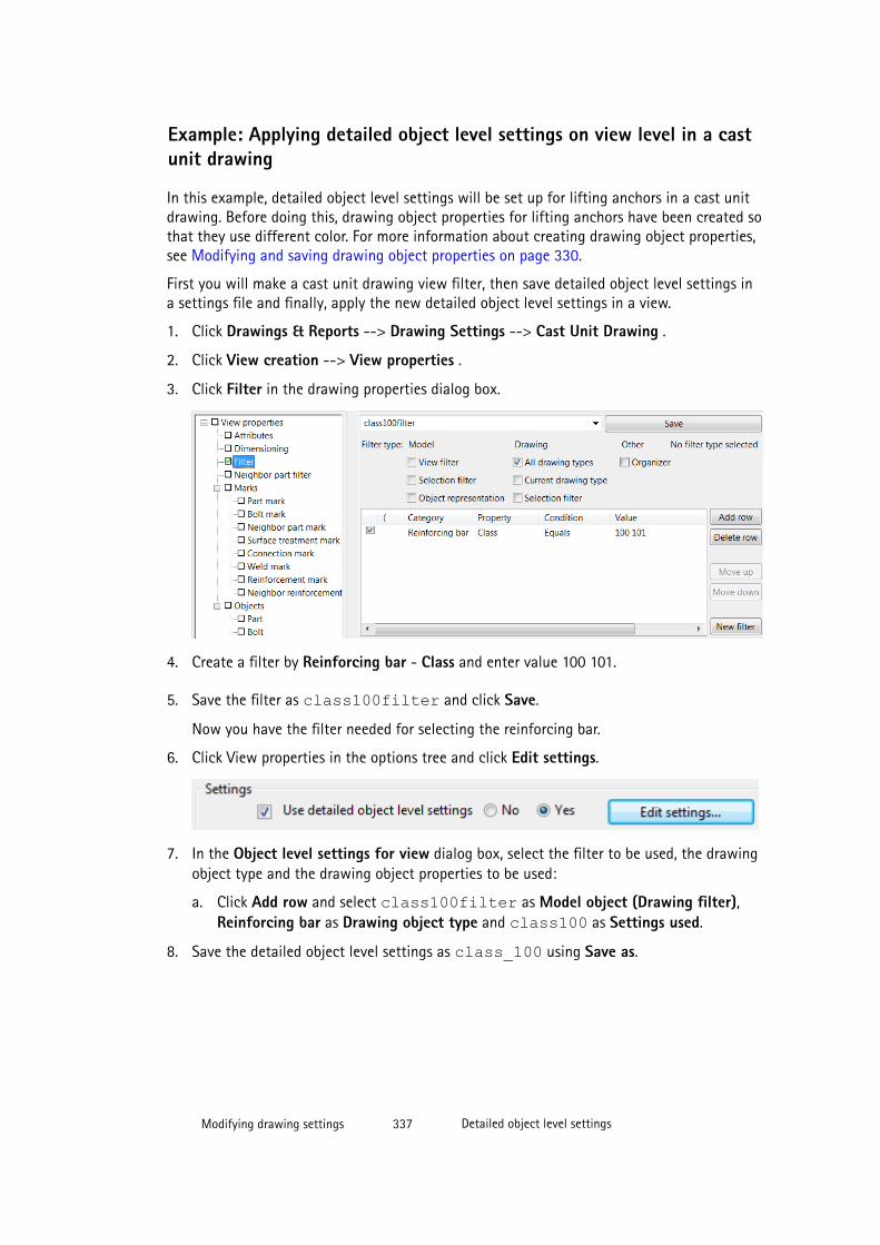
Example: Applying detailed object level settings on view level in a castunit drawing
In this example, detailed object level settings will be set up for lifting anchors in a cast unitdrawing. Before doing this, drawing object properties for lifting anchors have been created sothat they use different color. For more information about creating drawing object properties,see Modifying and saving drawing object properties on page 330.
First you will make a cast unit drawing view filter, then save detailed object level settings ina settings file and finally, apply the new detailed object level settings in a view.
1. Click Drawings & Reports --> Drawing Settings --> Cast Unit Drawing .
2. Click View creation --> View properties .
3. Click Filter in the drawing properties dialog box.
4. Create a filter by Reinforcing bar - Class and enter value 100 101.
5. Save the filter as class100filter and click Save.
Now you have the filter needed for selecting the reinforcing bar.
6. Click View properties in the options tree and click Edit settings.
7. In the Object level settings for view dialog box, select the filter to be used, the drawingobject type and the drawing object properties to be used:
a. Click Add row and select class100filter as Model object (Drawing filter),Reinforcing bar as Drawing object type and class100 as Settings used.
8. Save the detailed object level settings as class_100 using Save as.
Modifying drawing settings 337 Detailed object level settings
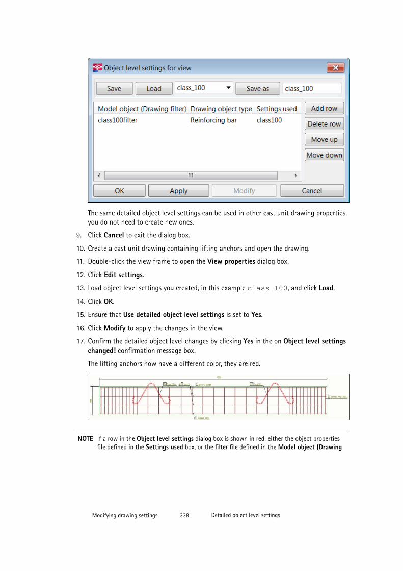
The same detailed object level settings can be used in other cast unit drawing properties,you do not need to create new ones.
9. Click Cancel to exit the dialog box.
10. Create a cast unit drawing containing lifting anchors and open the drawing.
11. Double-click the view frame to open the View properties dialog box.
12. Click Edit settings.
13. Load object level settings you created, in this example class_100, and click Load.
14. Click OK.
15. Ensure that Use detailed object level settings is set to Yes.
16. Click Modify to apply the changes in the view.
17. Confirm the detailed object level changes by clicking Yes in the on Object level settingschanged! confirmation message box.
The lifting anchors now have a different color, they are red.
NOTE If a row in the Object level settings dialog box is shown in red, either the object propertiesfile defined in the Settings used box, or the filter file defined in the Model object (Drawing
Modifying drawing settings 338 Detailed object level settings
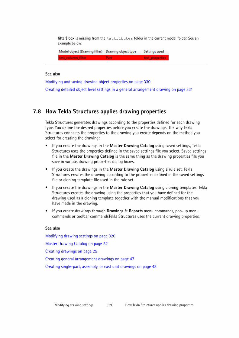
filter) box is missing from the \attributes folder in the current model folder. See anexample below:
See also
Modifying and saving drawing object properties on page 330
Creating detailed object level settings in a general arrangement drawing on page 331
7.8 How Tekla Structures applies drawing properties
Tekla Structures generates drawings according to the properties defined for each drawingtype. You define the desired properties before you create the drawings. The way TeklaStructures connects the properties to the drawing you create depends on the method youselect for creating the drawing:
• If you create the drawings in the Master Drawing Catalog using saved settings, TeklaStructures uses the properties defined in the saved settings file you select. Saved settingsfile in the Master Drawing Catalog is the same thing as the drawing properties file yousave in various drawing properties dialog boxes.
• If you create the drawings in the Master Drawing Catalog using a rule set, TeklaStructures creates the drawing according to the properties defined in the saved settingsfile or cloning template file used in the rule set.
• If you create the drawings in the Master Drawing Catalog using cloning templates, TeklaStructures creates the drawing using the properties that you have defined for thedrawing used as a cloning template together with the manual modifications that youhave made in the drawing.
• If you create drawings through Drawings & Reports menu commands, pop-up menucommands or toolbar commandsTekla Structures uses the current drawing properties.
See also
Modifying drawing settings on page 320
Master Drawing Catalog on page 52
Creating drawings on page 25
Creating general arrangement drawings on page 47
Creating single-part, assembly, or cast unit drawings on page 48
Modifying drawing settings 339 How Tekla Structures applies drawing properties
7.9 Drawing layoutA drawing layout defines which drawing tables to include in the drawing and the set of rulesfor increasing the drawing size when necessary. The layout connects a set of drawing tablelayouts and drawing sizes. Tekla Structures selects the smallest defined drawing size that willfit the drawing views and the connected table layout. This tells Tekla Structures whichelements to include in the drawing automatically. Each drawing layout has its own:
• Table layouts
• Fixed drawing sizes
• Calculated drawing sizes
Tekla Structures has several predefined drawing layouts. Each drawing type; assembly, single-part, cast unit, general arrangement, and multidrawing, has its own layouts. You can alsocreate customized layouts.
Using different layouts you can, for example, set assembly drawings to use A1 and A2 sizedrawing sheets, and single-part drawings to use A3 and A4 sheets. Another example is thatyou may want to include a material list in assembly drawings, but not in generalarrangement drawings.
Tekla Structures saves the new layouts you create in separate files with the file nameextension .lay. The layout files are located in the \attributes folder in the model folder.You can copy them to project or firm folders defined by advanced options XS_FIRM andXS_PROJECT.
See also
Table layouts on page 340
Tables on page 342
Creating a new layout on page 343
Setting margins and spaces for drawing views on page 346
Creating and adding a new table layout on page 345
Adding tables in a table layout on page 346
Replacing a table with another one on page 347
Setting the properties of tables in a table layout on page 348
Key plans on page 349
Adding a DXG/DXF file in a table layout on page 351
Modifying tables in Template Editor on page 353
Selecting a new layout on page 352
Modifying drawing settings 340 Drawing layout

Table layouts
A table layout is a group of tables or templates included in a drawing of a certain type andsize. The layout defines:
• Which tables are included in the drawing
• Where the tables are located in the drawing
• How much space Tekla Structures leaves between the drawing frame and views andbetween the drawing views
Table layouts define the background of the drawing, not the number or location of thedrawing views to include. You can use the same table layout with different drawing sizes, orgive each drawing size its own table layout. For example, if the number of views changes in adrawing and Tekla Structures chooses a new drawing size, Tekla Structures may also chooseanother table layout.
The examples below illustrate the relationship between the table layout and drawing views.The drawing views are blue, and the elements of the table layout are green.
Below is an example of a GA drawing layout.
1. General arrangement drawing view
2. Part list on assembly or cast unit level
3. Revision table and title block
Below is an example of an assembly drawing.
Modifying drawing settings 341 Drawing layout
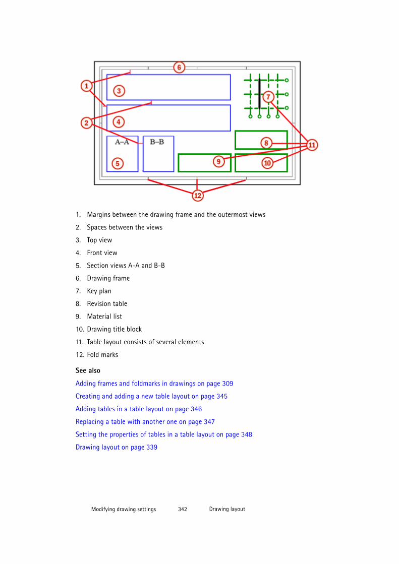
1. Margins between the drawing frame and the outermost views
2. Spaces between the views
3. Top view
4. Front view
5. Section views A-A and B-B
6. Drawing frame
7. Key plan
8. Revision table
9. Material list
10. Drawing title block
11. Table layout consists of several elements
12. Fold marks
See also
Adding frames and foldmarks in drawings on page 309
Creating and adding a new table layout on page 345
Adding tables in a table layout on page 346
Replacing a table with another one on page 347
Setting the properties of tables in a table layout on page 348
Drawing layout on page 339
Modifying drawing settings 342 Drawing layout

Tables
The term table refers to various elements of the drawing layout, such as:
• Tables (such as revision tables)
• Title blocks
• Lists (such as part and bolt lists)
• General notes
• Key plans
• DWG/DXF files
Tables contain information on model objects. If you change the model, Tekla Structuresupdates the contents of the affected drawings and tables. The contents of the tables arefilled in by Tekla Structures at run time. You can create tables in Template Editor. In TemplateEditor, the tables are referred to as templates.
The available graphical templates are read from the following folders in the following order,and shown in the Available tables list in the Tables dialog box:
• Template directory (XS_TEMPLATE_DIRECTORY)
• Current model folder
• Project folder (XS_PROJECT)
• Firm folder (XS_FIRM)
• Environment-specific system templates folder(XS_TEMPLATE_DIRECTORY_SYSTEM)
• System folder (XS_SYSTEM)
See also
Modifying tables in Template Editor on page 353
Setting the properties of tables in a table layout on page 348
Adding tables in a table layout on page 346
Replacing a table with another one on page 347
Creating a new layout
If none of the layouts meet your needs, you can create a new one from scratch or on thebasis of an existing layout.
To create a layout:
1. Click Drawings & Reports --> Drawing Settings --> Drawing Layout .
2. Do one of the following:
Modifying drawing settings 343 Drawing layout

• To create a new layout from scratch, enter the name of the new layout in the boxunder the list of layouts and click Add.
The new layout is empty.
• To create a new layout on the basis of an existing layout, select a layout from the listand enter a new name for the new layout in the box under the list of layouts andclick Add.
The contents of the new layout are the same as those of the layout you selected fromthe list.
3. Define and add table layouts and fixed and calculated sizes in the empty layout or modifythe table layouts and fixed and calculated sizes in the layout you created on the basis ofan existing layout.
4. Close the dialog box.
Now you can use the new layout in your drawings.
See also
Defining fixed sizes on page 344
Defining calculated sizes on page 345
Drawing layout on page 339
Defining fixed sizes
Fixed drawing sizes have a specific size (width and height), and table layout. You can usefixed sizes in autosizing.
To define the fixed drawing sizes in a layout:
1. Click Drawings & Reports --> Drawing Settings --> Drawing Layout .
2. Select the layout and click Fixed sizes.
3. Select a fixed size from the list.
To create a new size, enter its name and click Add.
4. Enter the width and height.
5. Select the table layout.
6. Click Update.
7. Repeat steps 3–6 for each fixed size.
8. Click Apply or OK.
TIP Use fixed sizes when you print drawings to small (A4 and A3) printing devices.
Single-part and assembly drawings also typically use fixed drawing sizes.
Modifying drawing settings 344 Drawing layout
See also
Creating a new layout on page 343
Drawing size and drawing view scale on page 354
Defining calculated sizes
You can use calculated drawing sizes to define the rules Tekla Structures follows when itautomatically adjusts drawing size. You can also connect layouts to drawing sizes that meetcertain criteria.
To set the rules and connect layouts:
1. Click Drawings & Reports --> Drawing Settings --> Drawing Layout .
2. Select the layout and click Calculated sizes.
3. Use Increasing step to define the interval by which Tekla Structures increases thedrawing size when it needs to.
This can be set individually for drawing width and height. You can also define themaximum size of the drawing. If the drawing exceeds the width or height limit you sethere, Tekla Structures uses an oversize sheet with no table layout.
4. You can connect a layout to drawings that meet one of the following size criteria:
• Size A4 for drawings exactly this size
• Size A3 for drawings exactly this size
• Height = A3 for drawings having the same height as an A3 sheet (=297 mm)
• Height > A3 for drawings with a larger height than A3.
For each size, Tekla Structures makes the table layouts available depending on thelayout you select.
5. Click OK or Apply.
See also
Creating a new layout on page 343
Drawing size and drawing view scale on page 354
Creating and adding a new table layout
To create a new table layout and add in a layout:
1. Click Drawings & Reports --> Drawing Settings --> Drawing Layout .
2. Select a layout from the list of layouts.
3. Click Table layouts to display the Table Layouts dialog box.
Modifying drawing settings 345 Drawing layout
4. Enter the name of the new table layout in the box under the list of table layouts andclick Add.
5. Enter the margins between the drawing views and frame, and the spaces between twodrawing views in Margins and Spaces.
6. Click Tables to display the Tables dialog box.
7. Add tables in your table layout, define the location, scale and transparency settings foreach table.
8. After each table you add, click Update.
9. Click OK or Apply to save the table layout.
See also
Table layouts on page 340
Setting margins and spaces for drawing views on page 346
Setting the properties of tables in a table layout on page 348
Setting margins and spaces for drawing views
Table layouts define the margins between the drawing views and the frame, and the spacebetween two drawing views.
A margin is the width or height from the outermost drawing views to the drawing frame. Aspace is the horizontal or vertical distance between two drawing views.
To set the margins and spaces:
1. Click Drawings & Reports --> Drawing Settings --> Drawing Layout .
2. Select a layout and click Table layout.
3. Select the table layout on the list.
4. Enter margins and spaces.
5. Click Update.
6. Repeat step 3–5 for each table layout.
7. Click OK or Apply.
See also
Table layouts on page 340
Creating and adding a new table layout on page 345
Modifying drawing settings 346 Drawing layout
Adding tables in a table layoutTo add tables (Template Editor templates, key plans, DWG/DXF files) in a table layout:
1. Open the Tables dialog box by clicking Drawings & Reports --> Drawing Settings -->Drawing Layout .
2. Select a drawing layout and click Table Layout .
3. Select a table layout and click Tables.
4. On the Available tables list, double-click each table you want to include in the tablelayout.
You can also use the arrow buttons to add and remove tables.
5. Set the table properties as required for each table you add.
6. Click Update.
7. Click OK or Apply.
See also
Setting the properties of tables in a table layout on page 348
Table layouts on page 340
Modifying tables in Template Editor on page 353
Replacing a table with another one
Be careful when you delete tables from table layouts. Other tables may use the table as areference object. Also, when you replace tables with new ones, the new ones do not inheritthe location of the deleted tables.
To delete a table from a table layout and replace it with a new one:
1. Select Drawings & Reports --> Drawing Settings --> Drawing Layout to display theLayout dialog box.
2. Select a drawing layout and click Table Layouts.
3. Select a table layout and click Tables.
4. Check if the table you are going to delete is used as a reference the table for anothertable. If it does, and you delete the table, you cannot see any tables at all in the layout.
5. Delete the table that you wish to replace by selecting the table from the Chosen tableslist and clicking the left arrow.
6. Select a new table from the Available tables list and add it to the Chosen tables list byclicking the right arrow.
7. Define the binding point of the new table and its location relative to the reference object.
8. Set the transparency, scale and the distance from the reference object, if necessary.
Modifying drawing settings 347 Drawing layout

9. Click Update and OK.
10. Click Update and OK in the Table Layouts dialog box.
11. Click OK in the Layout dialog box.
See also
Table layouts on page 340
Adding tables in a table layout on page 346
Setting the properties of tables in a table layout
You can define the location of each individual table in a table layout by binding it to thedrawing frame or to another table.
In the illustration below, the lower right corner of the drawing title (table) is bound to thelower right corner of the drawing frame (reference).
To set the properties of a table in a table layout:
1. Open the Tables dialog box by clicking Drawings & Reports --> Drawing Settings -->Drawing Layout .
2. Select a layout and click Table Layout .
3. Select a table layout and click Tables.
4. Select a table from the Chosen tables list.
5. Choose one of the table corners as its reference point, and select the check box in thatcorner.
6. In the Reference box, select the reference object, which can be another table included inthe table layout, or the drawing frame.
7. Choose the reference point of the reference object, and select the check box in theappropriate corner.
Modifying drawing settings 348 Drawing layout

8. In the Vector between corners boxes, define the horizontal and vertical distance of thetable from the reference object.
By default, Tekla Structures places tables side by side.
9. In Scale, set the size of the table relative to its original size.
Each table can have its own scale.
10. If you want the table to be transparent, select the Transparent check box.
A transparent table can overlap with another table, view or drawing object.
11. Click Update.
12. Repeat steps 2–11 for all the tables on the Chosen tables list.
13. Click OK or Apply to save the table layout.
TIP You can also position a table in the midpoint of a frame or table boundary by selectingtwo reference points, for example, the lower left and right corners.
NOTE If you do not use the right combinations of reference points for tables and bindingobjects, Tekla Structures may position drawing tables outside the drawing.
See also
Table layouts on page 340
Tables on page 342
Adding tables in a table layout on page 346
Modifying drawing settings 349 Drawing layout
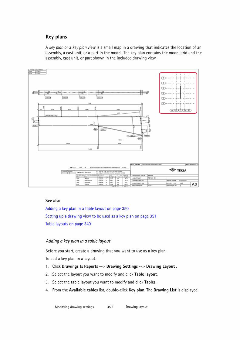
Key plans
A key plan or a key plan view is a small map in a drawing that indicates the location of anassembly, a cast unit, or a part in the model. The key plan contains the model grid and theassembly, cast unit, or part shown in the included drawing view.
See also
Adding a key plan in a table layout on page 350
Setting up a drawing view to be used as a key plan on page 351
Table layouts on page 340
Adding a key plan in a table layout
Before you start, create a drawing that you want to use as a key plan.
To add a key plan in a layout:
1. Click Drawings & Reports --> Drawing Settings --> Drawing Layout .
2. Select the layout you want to modify and click Table layout.
3. Select the table layout you want to modify and click Tables.
4. From the Available tables list, double-click Key plan. The Drawing List is displayed.
Modifying drawing settings 350 Drawing layout
5. Select the drawing that you want to use as a key plan drawing and click OK.
6. From the Chosen tables list, select Key plan and set the key plan properties.
7. Click Update.
8. Click OK.
Now you can create a drawing using the layout containing the key plan.Check the drawingproperties before creating a drawing to ensure that you are using the correct layout.
See also
Setting the properties of tables in a table layout on page 348
Setting up a drawing view to be used as a key plan
Tekla Structures automatically includes the correct part in the key plan. Drawings thatcontain only one view of the correct scale can be used as a key plan. Tekla Structures onlyuses the view from the drawing, and the view position, drawing size, and templates are notrelevant to a key plan drawing.
Set the view properties for the key plan as follows:
1. Open the drawing and double-click the view boundary to open the View Propertiesdialog box.
2. Set the desired drawing scale.
Tekla Structures uses the scale of the key plan view in every drawing using it. You cannotchange the scale in the layout properties.
3. Set the drawing view boundaries so that all parts are visible. To do this, change the xmin, x max, y min, and y max, or select the view and drag the boundary using thehandles on the x and y axes of the view.
4. Set other view properties.
All the changes you make in the properties affect the key plan. For example, if you setpart and bolt marks to be visible, they will also be visible in the key plan.
5. Click Modify.
NOTE Do not filter out anything indicated with not in drawings that will be used as key plans . TeklaStructures clears the not check boxes in the filter automatically when the key plan is insertedin another drawing.
See also
Key plans on page 349
Modifying drawing settings 351 Drawing layout
Adding a DXG/DXF file in a table layout
You can add DWG and DXF files in table layouts. For example, you might have some details ina DWG or DXF file that you want to show in certain types of drawings and therefore add thefile in the layout.
To add a DWG or a DXF file in a table layout:
1. Click Drawings & Reports --> Drawing Settings --> Drawing Layout .
2. Select the layout you want to modify and click Table layout.
3. Select the table layout you want to modify and click Tables.
4. From the Available tables list, double-click DWG/DXF.
5. Select the DWG/DXF file that you want to add.
6. Click OK.
7. From the Chosen tables list, click the selected DWG/DXF file and set the properties asrequired.
For example, set the required scale and define the location for the DWG/DXF file in thedrawing. Test the layout before using it to ensure, that the settings are as you wish.
8. Click Update.
9. Click OK.
Now you can create a drawing using the layout containing the DWG/DXF file. Check thedrawing properties before creating a drawing to ensure that you are using the correct layout.
See also
Setting the properties of tables in a table layout on page 348
Adding links to DWG and DXF files on page 199
Selecting a new layout
You can define which layout to use in a drawing in drawing properties. The layoutinformation is stored in the drawing property files. We recommend that you create as manyproperty files as you need different layouts for the different drawing types.
To select a new layout and save the layout information in a drawing property file:
1. Click Drawings & Reports --> Drawing Settings and select the drawing type.
2. Load the properties that you want to change.
3. Click Layout.
4. Select a new layout from the Layout list.
5. General arrangement drawings: Click OK.
Modifying drawing settings 352 Drawing layout
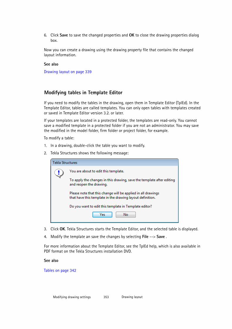
6. Click Save to save the changed properties and OK to close the drawing properties dialogbox.
Now you can create a drawing using the drawing property file that contains the changedlayout information.
See also
Drawing layout on page 339
Modifying tables in Template Editor
If you need to modify the tables in the drawing, open them in Template Editor (TplEd). In theTemplate Editor, tables are called templates. You can only open tables with templates createdor saved in Template Editor version 3.2. or later.
If your templates are located in a protected folder, the templates are read-only. You cannotsave a modified template in a protected folder if you are not an administrator. You may savethe modified in the model folder, firm folder or project folder, for example.
To modify a table:
1. In a drawing, double-click the table you want to modify.
2. Tekla Structures shows the following message:
3. Click OK. Tekla Structures starts the Template Editor, and the selected table is displayed.
4. Modify the template an save the changes by selecting File --> Save .
For more information about the Template Editor, see the TplEd help, which is also available inPDF format on the Tekla Structures installation DVD.
See also
Tables on page 342
Modifying drawing settings 353 Drawing layout
7.10 Drawing size and drawing view scale
Tekla Structures offers you several combinations of settings that you can use for defining thedrawing size and the drawing view scale. Which one you use, depends on your needs:
• If you always want to use a certain scale, then you would set the exact scale to be usedand let Tekla Structures automatically select the drawing size that suits the selectedscale. This is called autosizing. You can define different scales for main views and sectionviews. All main views in a drawing automatically use the same scale unless you fine-tuneindividual views manually.
• If you always need to use a certain drawing size, for example, A3, A4 or A1, then youwould set the size and let Tekla Structures automatically select the drawing view scalethat suits the selected size. This is called autoscaling.
• If you are not bound to any specific drawing sizes or drawing view scales, you mightwant to let Tekla Structures take care of both.
See also
Modifying and saving automatic drawing properties before creating drawings on page 325
Using exact drawing size and automatic drawing view scale on page 355
Using exact drawing view scale and automatic drawing size on page 354
Autoscaling and autosizing drawings on page 356
Using exact drawing view scale and automatic drawing size
You can let Tekla Structures find appropriate sizes and table layouts for drawings. This is veryuseful if, for example, the number, size, or location of drawing views might change. TeklaStructures automatically updates drawings to adapt to these changes by using differentdrawing sizes and table layouts.
To define exact drawing view scale and let Tekla Structures automatically select the suitabledrawing size:
1. Click Drawings & Reports --> Drawing Settings and select the drawing type.
2. Load the properties that you want to change.
3. Click Layout.
4. Set Size definition mode to Autosize.
5. Select the set of drawing sizes for Tekla Structures to use. You have the options:
• Calculated sizes: Use this when you want to define the rules that Tekla Structuresfollows when it tries to adjust the drawing size.
• Fixed sizes: Use this when you want Tekla Structures to use fixed drawing sizes A2,A3, A4, etc.
Modifying drawing settings 354 Drawing size and drawing view scale
• Calculated/fixed sizes: Use this when you want Tekla Structures to select thesmallest of the suitable sizes.
6. Go to the Scale tab and set Autoscale to No.
This way Tekla Structures uses the exact scale that you have set for the main views andsection views.
7. Click View creation, select the view and the properties that you want to change, andclick View properties.
8. On the Attributes 1 tab, set the desired Scale.
9. Click Save to save the drawing properties, then click OK and create the drawing.
When you create the drawing, Tekla Structures creates the views using the selected scale andselects the smallest drawing size where the views fit in the drawing. Tekla Structures mayalso need to change the table layout to adapt to the new drawing size. It will then useanother appropriate table layout within the same layout specified in drawing properties.
See also
Drawing size and drawing view scale on page 354
Drawing layout on page 339
View properties in drawings on page 551
Section view properties on page 555
Using exact drawing size and automatic drawing view scaleIf you need to use a specific size in your drawings, for example, A3, A2, or A1, you can specifythe exact size, and let Tekla Structures automatically select the suitable drawing view scale.The drawing size should always be smaller than the actual paper size to accommodate printermargins.
To use exact size and automatically scale the view:
1. Click Drawings & Reports --> Drawing Settings and select the drawing type.
2. Load the properties that you want to change.
3. Click Layout.
4. On the Drawing size tab, set Size definition mode to Specified size and enter thedrawing size.
5. Select the table layout from the Table layout list.
6. On the Scale tab, set Autoscale to Yes.
7. Set the main view and section view scales.
Enter the denominators of scales and separate them with spaces. For example, enter "510 15 20" for the scales 1/5, 1/10, 1/15, and 1/20.
Modifying drawing settings 355 Drawing size and drawing view scale
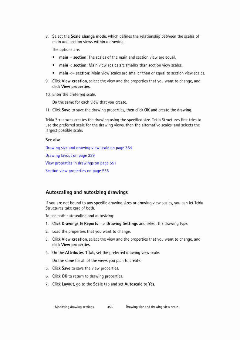
8. Select the Scale change mode, which defines the relationship between the scales ofmain and section views within a drawing.
The options are:
• main = section: The scales of the main and section view are equal.
• main < section: Main view scales are smaller than section view scales.
• main <= section: Main view scales are smaller than or equal to section view scales.
9. Click View creation, select the view and the properties that you want to change, andclick View properties.
10. Enter the preferred scale.
Do the same for each view that you create.
11. Click Save to save the drawing properties, then click OK and create the drawing.
Tekla Structures creates the drawing using the specified size. Tekla Structures first tries touse the preferred scale for the drawing views, then the alternative scales, and selects thelargest possible scale.
See also
Drawing size and drawing view scale on page 354
Drawing layout on page 339
View properties in drawings on page 551
Section view properties on page 555
Autoscaling and autosizing drawings
If you are not bound to any specific drawing sizes or drawing view scales, you can let TeklaStructures take care of both.
To use both autoscaling and autosizing:
1. Click Drawings & Reports --> Drawing Settings and select the drawing type.
2. Load the properties that you want to change.
3. Click View creation, select the view and the properties that you want to change, andclick View properties.
4. On the Attributes 1 tab, set the preferred drawing view scale.
Do the same for all of the views you plan to create.
5. Click Save to save the view properties.
6. Click OK to return to drawing properties.
7. Click Layout, go to the Scale tab and set Autoscale to Yes.
Modifying drawing settings 356 Drawing size and drawing view scale
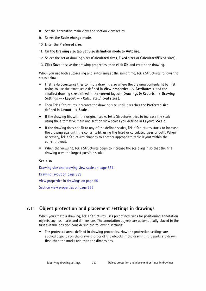
8. Set the alternative main view and section view scales.
9. Select the Scale change mode.
10. Enter the Preferred size.
11. On the Drawing size tab, set Size definition mode to Autosize.
12. Select the set of drawing sizes (Calculated sizes, Fixed sizes or Calculated/Fixed sizes).
13. Click Save to save the drawing properties, then click OK and create the drawing.
When you use both autoscaling and autosizing at the same time, Tekla Structures follows thesteps below:
• First Tekla Structures tries to find a drawing size where the drawing contents fit by firsttrying to use the exact scale defined in View properties --> Attributes 1 and thesmallest drawing size defined in the current layout ( Drawings & Reports --> DrawingSettings --> Layout --> Calculated/Fixed sizes ).
• Then Tekla Structures increases the drawing size until it reaches the Preferred sizedefined in Layout --> Scale .
• If the drawing fits with the original scale, Tekla Structures tries to increase the scaleusing the alternative main and section view scales you defined in Layout >Scale.
• If the drawing does not fit to any of the defined scales, Tekla Structures starts to increasethe drawing size until the contents fit, using the fixed or calculated sizes or both. Whennecessary, Tekla Structures changes to another appropriate table layout within thecurrent layout.
• When the views fit, Tekla Structures begin to increase the scale again so that the finaldrawing uses the largest possible scale.
See also
Drawing size and drawing view scale on page 354
Drawing layout on page 339
View properties in drawings on page 551
Section view properties on page 555
7.11 Object protection and placement settings in drawingsWhen you create a drawing, Tekla Structures uses predefined rules for positioning annotationobjects such as marks and dimensions. The annotation objects are automatically placed in thefirst suitable position considering the following settings:
• The protected areas defined in drawing properties. How the protection settings areapplied depends on the drawing order of the objects in the drawing: the parts are drawnfirst, then the marks and then the dimensions.
Modifying drawing settings 357 Object protection and placement settings in drawings

• The placing and leader line type settings of the annotation objects defined in theannotation object properties. Marks are usually drawn before dimensions, but if themarks have leader lines, they are drawn after the dimensions.
• The predefined mark location and part orientation settings for some marks.
• The modeling direction of parts.
You can modify the placement settings and select the leader line type in the object leveldialog boxes of texts, notes, marks and dimensions. On the object level, you can select if youwant to use fixed or free placement. The protection settings for the whole drawing are alsoconsidered when you add annotation objects manually.
You can access the Protection Properties through the drawing properties dialog box:
When you create a drawing, Tekla Structures places the views in the drawing according thesettings in the drawing layout and view properties. In final drawings, you can select whetherto use fixed or free view placement of views.
See also
Protected areas on page 358
Protecting areas in drawings on page 360
Defining placement settings for annotation objects on page 362
Defining automatic free or fixed placement of drawing views on page 363
Defining placement settings for dimensions on page 362
Placement properties for annotation objects on page 612
Protected areasYou can define protected areas in drawings to prevent text, marks or dimensions from beingplaced in the area. When Tekla Structures places text, marks, dimensions or other annotationobjects in a drawing, it first checks the protection settings.
The drawing properties files contain predefined protection properties, which you may change.When you load the drawing properties, the protection settings in the loaded file are appliedin your drawing.
Below is an example of the protection properties dialog with explanations of the selections.
Modifying drawing settings 358 Object protection and placement settings in drawings
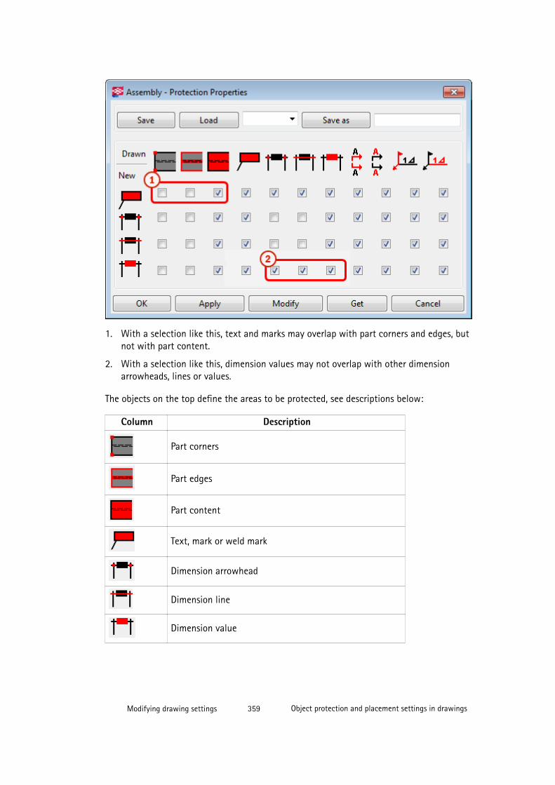
1. With a selection like this, text and marks may overlap with part corners and edges, butnot with part content.
2. With a selection like this, dimension values may not overlap with other dimensionarrowheads, lines or values.
The objects on the top define the areas to be protected, see descriptions below:
Column Description
Part corners
Part edges
Part content
Text, mark or weld mark
Dimension arrowhead
Dimension line
Dimension value
Modifying drawing settings 359 Object protection and placement settings in drawings
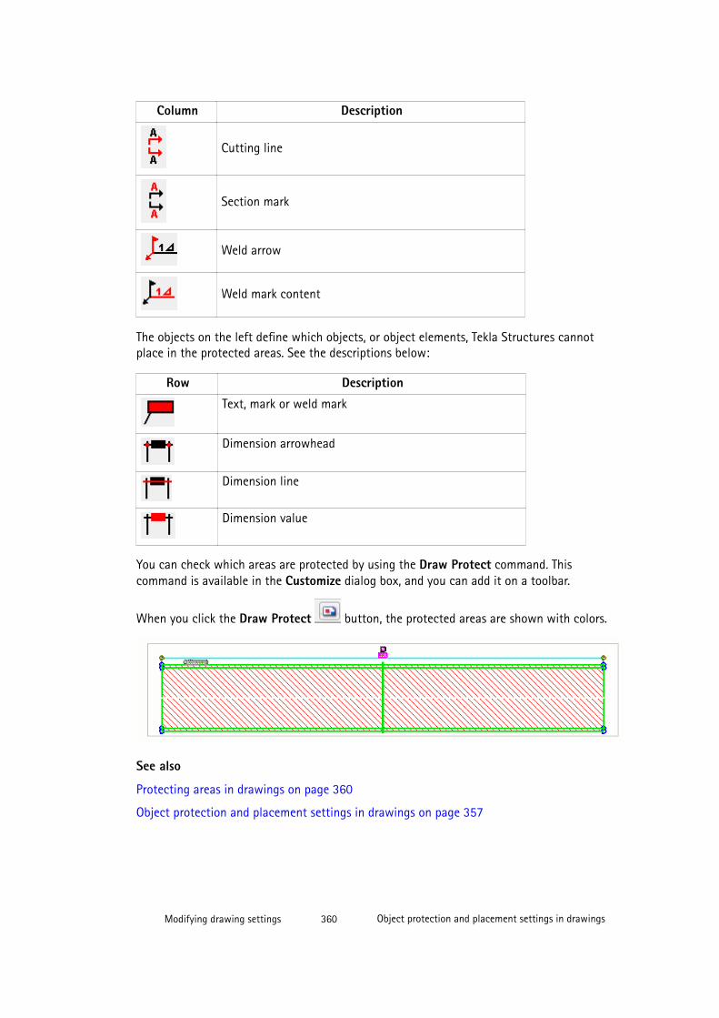
Column Description
Cutting line
Section mark
Weld arrow
Weld mark content
The objects on the left define which objects, or object elements, Tekla Structures cannotplace in the protected areas. See the descriptions below:
Row Description
Text, mark or weld mark
Dimension arrowhead
Dimension line
Dimension value
You can check which areas are protected by using the Draw Protect command. Thiscommand is available in the Customize dialog box, and you can add it on a toolbar.
When you click the Draw Protect button, the protected areas are shown with colors.
See also
Protecting areas in drawings on page 360
Object protection and placement settings in drawings on page 357
Modifying drawing settings 360 Object protection and placement settings in drawings
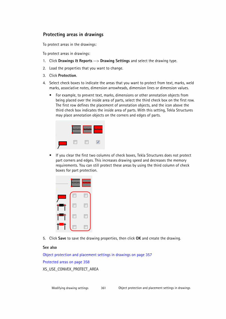
Protecting areas in drawings
To protect areas in the drawings:
To protect areas in drawings:
1. Click Drawings & Reports --> Drawing Settings and select the drawing type.
2. Load the properties that you want to change.
3. Click Protection.
4. Select check boxes to indicate the areas that you want to protect from text, marks, weldmarks, associative notes, dimension arrowheads, dimension lines or dimension values.
• For example, to prevent text, marks, dimensions or other annotation objects frombeing placed over the inside area of parts, select the third check box on the first row.The first row defines the placement of annotation objects, and the icon above thethird check box indicates the inside area of parts. With this setting, Tekla Structuresmay place annotation objects on the corners and edges of parts.
• If you clear the first two columns of check boxes, Tekla Structures does not protectpart corners and edges. This increases drawing speed and decreases the memoryrequirements. You can still protect these areas by using the third column of checkboxes for part protection.
5. Click Save to save the drawing properties, then click OK and create the drawing.
See also
Object protection and placement settings in drawings on page 357
Protected areas on page 358
XS_USE_CONVEX_PROTECT_AREA
Modifying drawing settings 361 Object protection and placement settings in drawings
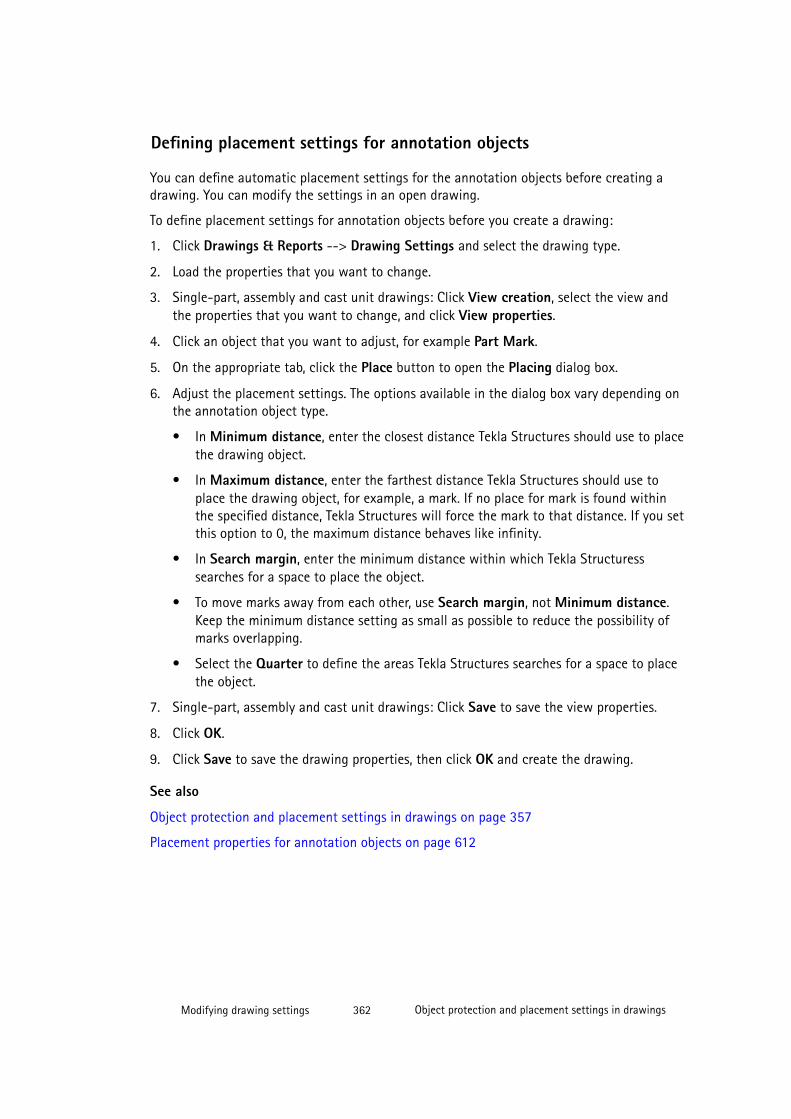
Defining placement settings for annotation objects
You can define automatic placement settings for the annotation objects before creating adrawing. You can modify the settings in an open drawing.
To define placement settings for annotation objects before you create a drawing:
1. Click Drawings & Reports --> Drawing Settings and select the drawing type.
2. Load the properties that you want to change.
3. Single-part, assembly and cast unit drawings: Click View creation, select the view andthe properties that you want to change, and click View properties.
4. Click an object that you want to adjust, for example Part Mark.
5. On the appropriate tab, click the Place button to open the Placing dialog box.
6. Adjust the placement settings. The options available in the dialog box vary depending onthe annotation object type.
• In Minimum distance, enter the closest distance Tekla Structures should use to placethe drawing object.
• In Maximum distance, enter the farthest distance Tekla Structures should use toplace the drawing object, for example, a mark. If no place for mark is found withinthe specified distance, Tekla Structures will force the mark to that distance. If you setthis option to 0, the maximum distance behaves like infinity.
• In Search margin, enter the minimum distance within which Tekla Structuresssearches for a space to place the object.
• To move marks away from each other, use Search margin, not Minimum distance.Keep the minimum distance setting as small as possible to reduce the possibility ofmarks overlapping.
• Select the Quarter to define the areas Tekla Structures searches for a space to placethe object.
7. Single-part, assembly and cast unit drawings: Click Save to save the view properties.
8. Click OK.
9. Click Save to save the drawing properties, then click OK and create the drawing.
See also
Object protection and placement settings in drawings on page 357
Placement properties for annotation objects on page 612
Modifying drawing settings 362 Object protection and placement settings in drawings
Defining placement settings for dimensions
You can control the space between parallel dimension lines and the location of thedimension in relation to the object it is dimensioning. You can also select whether to placeshort dimension text inside or outside the dimension.
In single-part, assembly and cast unit drawings, these settings can be defined only on objectlevel in an open drawing, saved into a dimension properties file and taken into use inDimensioning Rule Properties dialog box. In general arrangement drawings the settings canbe defined on drawing, view and object level.
To adjust dimension placement:
1. Go to the General tab of the Dimensions dialog box.
2. In Dimension lines spacing, enter the desired space between two parallel dimensionlines.
3. Select whether to place short dimension text inside or outside of the dimensions fromthe Short dimension list.
4. Click Place.
5. In Minimum distance, enter the closest distance Tekla Structures should use to place thedimension.
6. If Tekla Structures cannot place the dimension at the minimum distance, it moves thedimension by the value you enter in the Search margin box. Tekla Structures tries toplace the dimension using the Search margin value until it finds a place for thedimension.
7. Click OK to close the dimension placing dialog box.
8. Click OK.
NOTE Remember that in addition to dimension placement settings, the placement is also affectedby Protection properties.Tekla Structures uses the protection properties to prevent marks anddimensions from being placed in protected areas.
See also
Object protection and placement settings in drawings on page 357
Protecting areas in drawings on page 360
General dimension properties on page 556
Dimension appearance properties on page 560
Modifying drawing settings 363 Object protection and placement settings in drawings
Defining automatic free or fixed placement of drawing views
You can always maintain the views in the same location or let Tekla Structures find a suitableplace for the view during drawing updates using the Fixed or Free placement setting.
In general arrangement drawings, this setting can only be defined on view level in an opendrawing.
To define automatic free or fixed placement of in single-part, assembly and cast unitdrawings:
1. Click Drawings & Reports --> Drawing Settings and select the drawing type.
2. Load the properties that you want to change.
3. Click View creation, select the view and the properties that you want to change, andclick View properties.
4. On the Attributes 1 tab, select one of the following options:
• Set Place to Fixed to always keep the view in the same location when you updatethe drawing.
• Set Place to Free to let Tekla Structures find a suitable place for the view when youupdate the drawing.
5. Click Save to save the view properties.
6. Click OK to return to drawing properties.
7. Click Save to save the drawing properties, then click OK and create the drawing.
NOTE Arrange Drawing Views only affects views where the Place is set to Free. Fixed views arenot moved.
See also
Object protection and placement settings in drawings on page 357
7.12 Automatic drawing viewsAutomatic drawing views are views that you select to create in View creation beforecreating a single-part, assembly or cast unit drawing. You can define the desired drawingview properties before you create the drawings separately for each view.
When you create general arrangement drawings, you cannot select the views to be created inthe general arrangement properties dialog box, but you select them when you activate thedrawing creation. However, you can define automatic settings that apply to all the views youcreate in a general arrangement drawing.
See also
Defining the views to create in single-part, assembly and cast unit drawings on page 365
Modifying drawing settings 364 Automatic drawing views

Defining automatic view settings for general arrangement drawings on page 366
Defining view labels and view label marks on page 367
Setting the view projection type on page 369
Including single-part drawings in assembly drawings on page 370
Part orientation in drawing views on page 371
Showing neighbor parts in views on page 379
Shortening and lengthening parts on page 380
Unfolding polybeams in drawings on page 385
Undeforming deformed parts in drawings on page 386
Showing part openings and recesses in drawings on page 387
Setting automatic section view properties on page 389
Defining the views to create in single-part, assembly and cast unitdrawings
Before you create single-part, assembly or cast unit drawings, select the views that you wantto include automatically in View creation. At the same time, set the view properties.
To select the drawing views to be created and set the view properties:
1. Click Drawings & Reports --> Drawing Settings and select the drawing type.
2. Load the drawing properties file that you want to modify from the list at the top.
3. Click View creation.
4. Click the Attributes tab and change the settings as required.
5. Select the views you want to create. You can create as many views as you like.
• If you select off, Tekla Structures does not create the view, but dimensions the partsin the available views. If you set all four main views off, Tekla Structures will stillcreate one front view.
• If you select on, Tekla Structures always creates the view, even if it was not necessaryin order to show the dimensions. For section views, Tekla Structures creates oneadditional section view showing the middle of the main part. For end views, TeklaStructures creates an end view from one end of the main part.
• If you select auto, Tekla Structures creates the view if it is necessary in order to showthe dimensions. For section views, Tekla Structures creates the necessary number ofviews to show all the dimensions. For end views, Tekla Structures also creates anotherend view from the other end of the main part, if there are dimensions at that end.
Modifying drawing settings 365 Automatic drawing views
6. For each of the views that you create, select the view properties that you want to use inthe View properties column.
The lists contain predefined properties for different types of drawings, and also the viewproperties that you save on the View Properties panel.
7. Check the view properties for each view by selecting the view from the list and clickingView properties.
8. Check the settings on the Attributes 1, Attributes 2, and Label tabs and change themas required.
9. Modify dimensioning, mark and object settings as required.
10. Save the view properties by clicking Save.
11. Click OK.
12. Click Save to save the drawing properties, then click OK and create the drawing.
See also
View properties in drawings on page 551
Section view properties on page 555
Automatic drawing views on page 364
Modifying and saving automatic drawing properties before creating drawings on page 325
Defining automatic view settings for general arrangement drawings
Before you create general arrangement drawings, define the automatic view properties thatyou want to use.
To define the automatic view settings for general arrangement drawings:
1. Click Drawings & Reports --> Drawing Settings --> General Arrangement Drawing .
2. Load the drawing properties file that you want to modify from the list at the top.
3. On the Attributes tab, change the settings as required.
4. Go to the Shortening tab and define the part shortening settings.
5. Go to the Label tab and define the view label text, symbol and position.
6. If you want to create an anchor bolt plan drawing, go to the Anchor bolt plan tab andset Show as anchor bolt plan to Yes.
Change the other related settings as required.
7. Click OK to return to drawing properties.
8. Click Save to save the drawing properties, then click OK and create the drawing.
Modifying drawing settings 366 Automatic drawing views
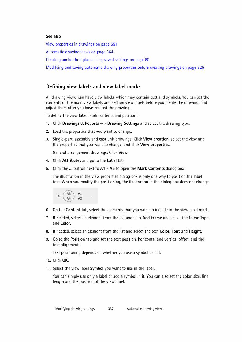
See also
View properties in drawings on page 551
Automatic drawing views on page 364
Creating anchor bolt plans using saved settings on page 60
Modifying and saving automatic drawing properties before creating drawings on page 325
Defining view labels and view label marks
All drawing views can have view labels, which may contain text and symbols. You can set thecontents of the main view labels and section view labels before you create the drawing, andadjust them after you have created the drawing.
To define the view label mark contents and position:
1. Click Drawings & Reports --> Drawing Settings and select the drawing type.
2. Load the properties that you want to change.
3. Single-part, assembly and cast unit drawings: Click View creation, select the view andthe properties that you want to change, and click View properties.
General arrangement drawings: Click View.
4. Click Attributes and go to the Label tab.
5. Click the ... button next to A1 - A5 to open the Mark Contents dialog box
The illustration in the view properties dialog box is only one way to position the labeltext. When you modify the positioning, the illustration in the dialog box does not change.
6. On the Content tab, select the elements that you want to include in the view label mark.
7. If needed, select an element from the list and click Add frame and select the frame Typeand Color.
8. If needed, select an element from the list and select the text Color, Font and Height.
9. Go to the Position tab and set the text position, horizontal and vertical offset, and thetext alignment.
Text positioning depends on whether you use a symbol or not.
10. Click OK.
11. Select the view label Symbol you want to use in the label.
You can simply use only a label or add a symbol in it. You can also set the color, size, linelength and the position of the view label.
Modifying drawing settings 367 Automatic drawing views
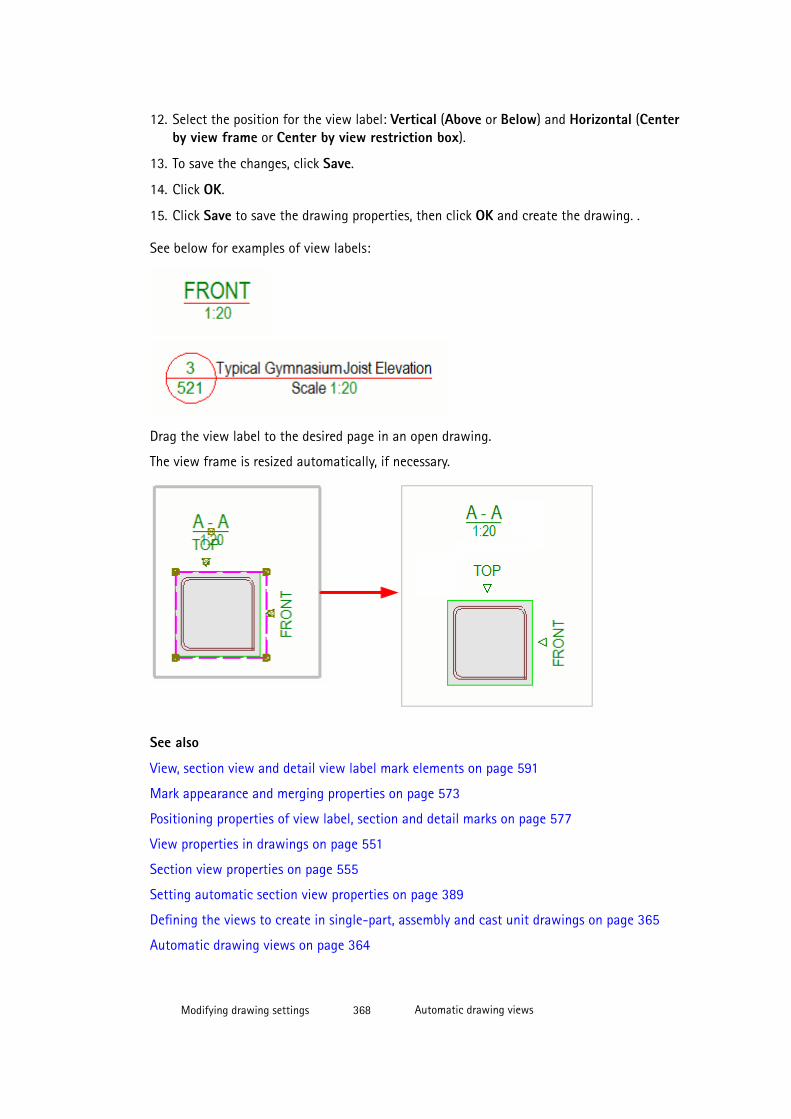
12. Select the position for the view label: Vertical (Above or Below) and Horizontal (Centerby view frame or Center by view restriction box).
13. To save the changes, click Save.
14. Click OK.
15. Click Save to save the drawing properties, then click OK and create the drawing. .
See below for examples of view labels:
Drag the view label to the desired page in an open drawing.
The view frame is resized automatically, if necessary.
See also
View, section view and detail view label mark elements on page 591
Mark appearance and merging properties on page 573
Positioning properties of view label, section and detail marks on page 577
View properties in drawings on page 551
Section view properties on page 555
Setting automatic section view properties on page 389
Defining the views to create in single-part, assembly and cast unit drawings on page 365
Automatic drawing views on page 364
Modifying drawing settings 368 Automatic drawing views
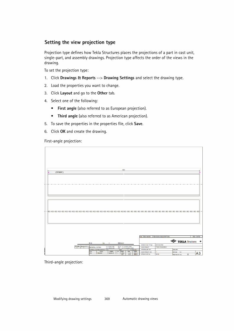
Setting the view projection type
Projection type defines how Tekla Structures places the projections of a part in cast unit,single-part, and assembly drawings. Projection type affects the order of the views in thedrawing.
To set the projection type:
1. Click Drawings & Reports --> Drawing Settings and select the drawing type.
2. Load the properties you want to change.
3. Click Layout and go to the Other tab.
4. Select one of the following:
• First angle (also referred to as European projection).
• Third angle (also referred to as American projection).
5. To save the properties in the properties file, click Save.
6. Click OK and create the drawing.
First-angle projection:
Third-angle projection:
Modifying drawing settings 369 Automatic drawing views
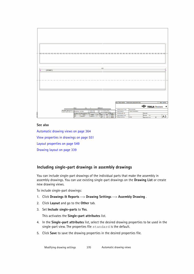
See also
Automatic drawing views on page 364
View properties in drawings on page 551
Layout properties on page 549
Drawing layout on page 339
Including single-part drawings in assembly drawings
You can include single-part drawings of the individual parts that make the assembly inassembly drawings. You can use existing single-part drawings on the Drawing List or createnew drawing views.
To include single-part drawings:
1. Click Drawings & Reports --> Drawing Settings --> Assembly Drawing .
2. Click Layout and go to the Other tab.
3. Set Include single-parts to Yes.
This activates the Single-part attributes list.
4. In the Single-part attributes list, select the desired drawing properties to be used in thesingle-part view. The properties file standard is the default.
5. Click Save to save the drawing properties in the desired properties file.
Modifying drawing settings 370 Automatic drawing views
6. Click OK and create the drawing.
The value of the advanced option XS_USE_EXISTING_SINGLE_PART_DRAWINGS_IN_ASSEMBLY_DRAWINGSaffects how Tekla Structures creates the single-part views. If the option is set to TRUE, TeklaStructures will use single-part drawings in the Drawing List. If it is set to FALSE, or if thereis no existing single-part drawing for a given part, a new view will be created according tothe Include single parts setting. The default value is FALSE.
See also
XS_USE_EXISTING_SINGLE_PART_DRAWINGS_IN_ASSEMBLY_DRAWINGS
XS_SINGLE_CENTERED_SCREW
XS_SINGLE_CLOSE_DIMENSIONS
XS_SINGLE_CLOSE_SHORT_DIMENSIONS
XS_SINGLE_COMBINE_DISTANCE
XS_SINGLE_COMBINE_MIN_DISTANCE
XS_SINGLE_COMBINE_WAY
XS_SINGLE_DIMENSION_TYPE
XS_SINGLE_DRAW_PART_AS
XS_SINGLE_EXCLUDE
XS_SINGLE_FORWARD_OFFSET
XS_SINGLE_NO_SHORTEN
XS_SINGLE_ORIENTATION_MARK
XS_SINGLE_PART_EXTREMA
XS_SINGLE_PART_SHAPE
XS_SINGLE_SCALE
XS_SINGLE_SCREW_INTERNAL
XS_SINGLE_SCREW_POSITIONS
XS_SINGLE_USE_WORKING_POINTS
XS_SINGLE_X_DIMENSION_TYPE
XS_NO_END_VIEWS_TO_INCLUDED_SINGLE_DRAWINGS
Adding single-part views in assembly drawings on page 132
Automatic drawing views on page 364
Modifying drawing settings 371 Automatic drawing views
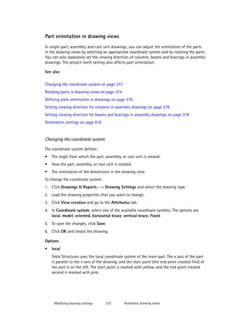
Part orientation in drawing views
In single-part, assembly, and cast unit drawings, you can adjust the orientation of the partsin the drawing views by selecting an appropriate coordinate system and by rotating the parts.You can also separately set the viewing direction of columns, beams and bracings in assemblydrawings. The project north setting also affects part orientation.
See also
Changing the coordinate system on page 372
Rotating parts in drawing views on page 374
Defining plate orientation in drawings on page 376
Setting viewing direction for columns in assembly drawings on page 378
Setting viewing direction for beams and bracings in assembly drawings on page 378
Orientation settings on page 616
Changing the coordinate system
The coordinate system defines:
• The angle from which the part, assembly, or cast unit is viewed.
• How the part, assembly, or cast unit is rotated.
• The orientation of the dimensions in the drawing view.
To change the coordinate system:
1. Click Drawings & Reports --> Drawing Settings and select the drawing type.
2. Load the drawing properties that you want to change.
3. Click View creation and go to the Attributes tab.
4. In Coordinate system, select one of the available coordinate systems. The options arelocal, model, oriented, horizontal brace, vertical brace, Fixed.
5. To save the changes, click Save.
6. Click OK and create the drawing.
Options
• local
Tekla Structures uses the local coordinate system of the main part. The x axis of the partis parallel to the x axis of the drawing, and the start point (the end point created first) ofthe part is on the left. The start point is marked with yellow, and the end point createdsecond is marked with pink.
Modifying drawing settings 372 Automatic drawing views
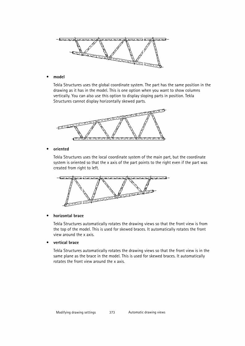
• model
Tekla Structures uses the global coordinate system. The part has the same position in thedrawing as it has in the model. This is one option when you want to show columnsvertically. You can also use this option to display sloping parts in position. TeklaStructures cannot display horizontally skewed parts.
• oriented
Tekla Structures uses the local coordinate system of the main part, but the coordinatesystem is oriented so that the x axis of the part points to the right even if the part wascreated from right to left.
• horizontal brace
Tekla Structures automatically rotates the drawing views so that the front view is fromthe top of the model. This is used for skewed braces. It automatically rotates the frontview around the x axis.
• vertical brace
Tekla Structures automatically rotates the drawing views so that the front view is in thesame plane as the brace in the model. This is used for skewed braces. It automaticallyrotates the front view around the x axis.
Modifying drawing settings 373 Automatic drawing views
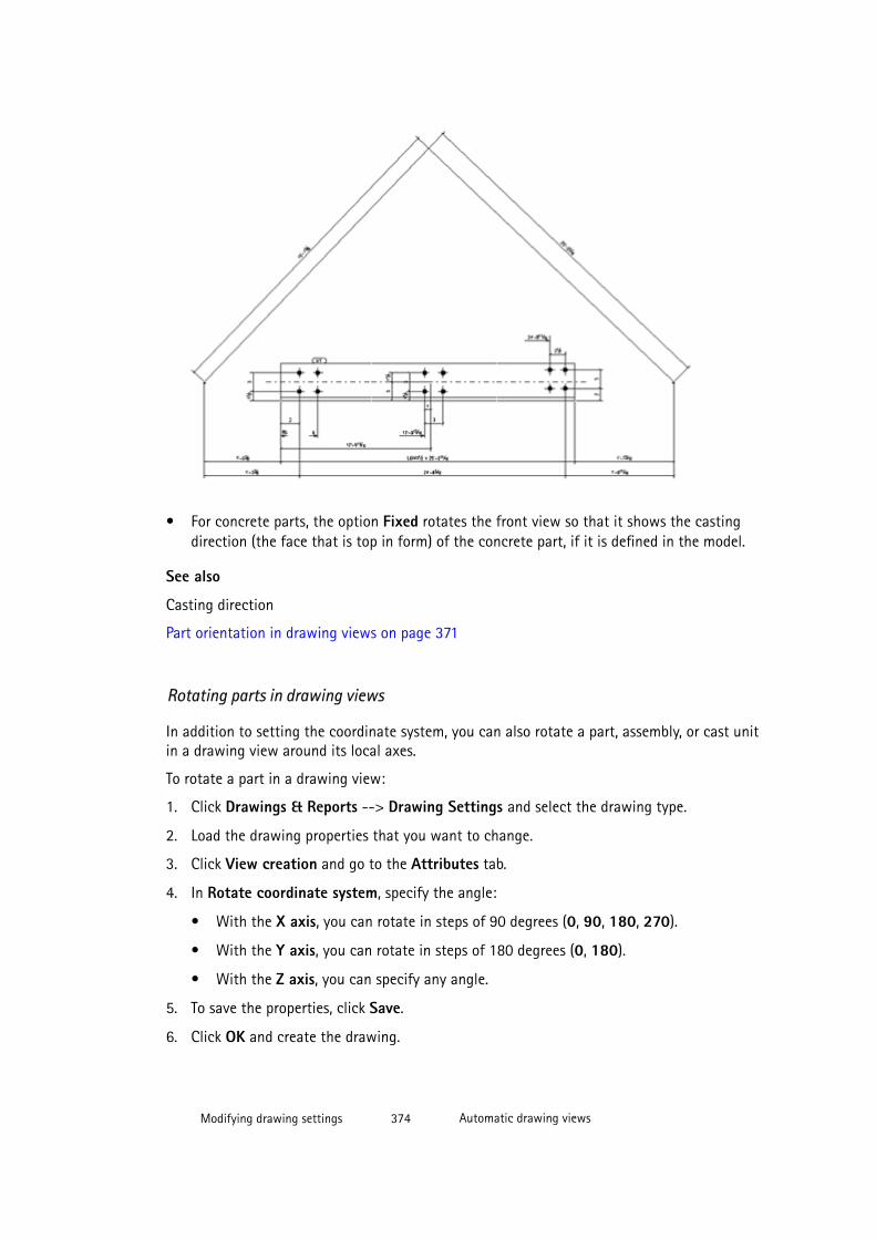
• For concrete parts, the option Fixed rotates the front view so that it shows the castingdirection (the face that is top in form) of the concrete part, if it is defined in the model.
See also
Casting direction
Part orientation in drawing views on page 371
Rotating parts in drawing views
In addition to setting the coordinate system, you can also rotate a part, assembly, or cast unitin a drawing view around its local axes.
To rotate a part in a drawing view:
1. Click Drawings & Reports --> Drawing Settings and select the drawing type.
2. Load the drawing properties that you want to change.
3. Click View creation and go to the Attributes tab.
4. In Rotate coordinate system, specify the angle:
• With the X axis, you can rotate in steps of 90 degrees (0, 90, 180, 270).
• With the Y axis, you can rotate in steps of 180 degrees (0, 180).
• With the Z axis, you can specify any angle.
5. To save the properties, click Save.
6. Click OK and create the drawing.
Modifying drawing settings 374 Automatic drawing views

See examples of rotating around the x axis below:
1. 0 degrees
2. 90 degrees
3. 180 degrees
4. 270 degrees
See an example of rotating the same part 180 degrees around the y axis below.
See an example of rotating the same part 30 degrees around the z axis below.
Modifying drawing settings 375 Automatic drawing views
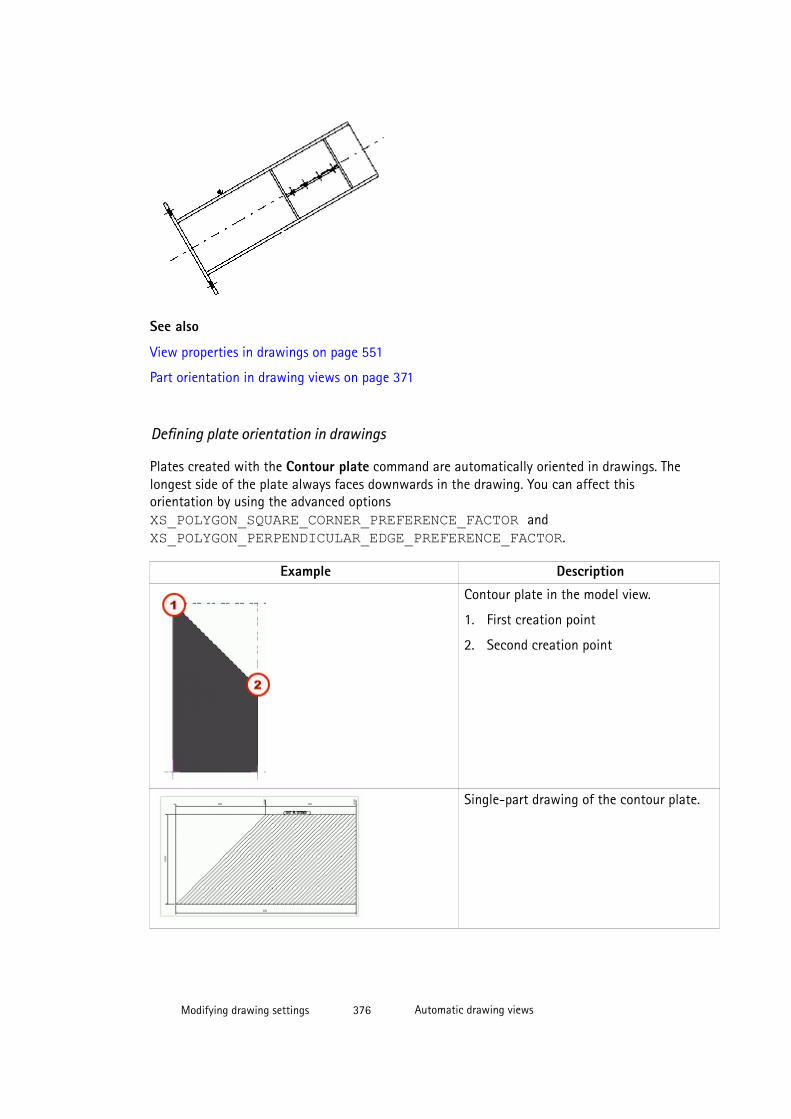
See also
View properties in drawings on page 551
Part orientation in drawing views on page 371
Defining plate orientation in drawings
Plates created with the Contour plate command are automatically oriented in drawings. Thelongest side of the plate always faces downwards in the drawing. You can affect thisorientation by using the advanced options XS_POLYGON_SQUARE_CORNER_PREFERENCE_FACTOR and XS_POLYGON_PERPENDICULAR_EDGE_PREFERENCE_FACTOR.
Example Description
Contour plate in the model view.
1. First creation point
2. Second creation point
Single-part drawing of the contour plate.
Modifying drawing settings 376 Automatic drawing views
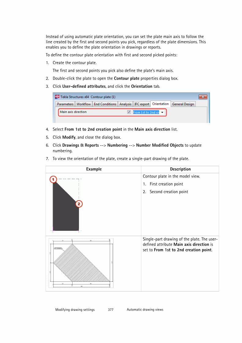
Instead of using automatic plate orientation, you can set the plate main axis to follow theline created by the first and second points you pick, regardless of the plate dimensions. Thisenables you to define the plate orientation in drawings or reports.
To define the contour plate orientation with first and second picked points:
1. Create the contour plate.
The first and second points you pick also define the plate’s main axis.
2. Double-click the plate to open the Contour plate properties dialog box.
3. Click User-defined attributes, and click the Orientation tab.
4. Select From 1st to 2nd creation point in the Main axis direction list.
5. Click Modify, and close the dialog box.
6. Click Drawings & Reports --> Numbering --> Number Modified Objects to updatenumbering.
7. To view the orientation of the plate, create a single-part drawing of the plate.
Example Description
Contour plate in the model view.
1. First creation point
2. Second creation point
Single-part drawing of the plate. The user-defined attribute Main axis direction isset to From 1st to 2nd creation point.
Modifying drawing settings 377 Automatic drawing views
Setting viewing direction for columns in assembly drawingsIn assembly drawings, you can define the front view direction separately for columns. Thedefault value for the front view direction for columns is As beam and bracing.
To define the direction of the front view for columns in assembly drawings:
1. Click Tools --> Options --> Options and go to the Orientation marks tab.
2. Use the Columns in assembly drawing options to set the front view direction ofcolumns:
• If you have set the coordinate system to local in View creation properties, TeklaStructures uses the coordinate system of the column when setting the direction ofthe front view.
• If you have set the coordinate system to oriented, the column is in a horizontalposition, and the direction of the front view is the option you select (North, East,South or West).
• If you have set the coordinate system to model, the column is in a vertical position,and the direction of the front view is the option you select (North, East, South orWest).
3. Click OK.
See also
Orientation settings on page 616
Part orientation in drawing views on page 371
Setting viewing direction for beams and bracings in assembly drawingsIn assembly drawings, you can define the front view direction separately for beams andbracings.
To define the viewing direction for beams and bracings:
1. Click Tools --> Options --> Options and go to the Orientation marks tab.
2. Use the Beams and bracings in assembly drawing options to set the front viewdirection. The default value is North or east.
• If the beam or bracing is parallel to the X axis of the model, it is also parallel to the Xaxis in the drawing.
• If you have set the coordinate system to model, and the beam or bracing is sloped, itis also sloped in the drawing.
3. Click OK.
Modifying drawing settings 378 Automatic drawing views

See also
Orientation settings on page 616
Part orientation in drawing views on page 371
Showing neighbor parts in views
Neighbor parts refer to (optionally shown) parts that are close to the part that is depicted ina drawing. Depending on settings, the neighbor parts may be parts somehow connected tothe part in question, or just parts that happen to be close by. You can select which neighborparts to show in views and also automatically extend the view boundary if necessary.
To control which neighbor parts to show and extend the view boundary automatically:
1. Click Drawings & Reports --> Drawing Settings and select the drawing type.
2. Load the properties that you want to change.
3. Single-part, assembly and cast unit drawings: Click View creation, select the view andthe properties that you want to change, and click View properties.
4. Click Neighbor part.
5. On the Visibility tab, select the parts and that you want to show using the followingoptions:
• None does not show neighbor parts.
• Connected parts shows all parts connected to the model object.
• Connecting parts shows only the parts the model object is connected to.
• All components combines the Connected parts and the Connecting parts options.
• By extreme show all parts within the boundaries of the main and secondary part.This setting is affected by the value entered for View extension for neighbor partson the Attributes (1) tab.
• Main/Secondary parts: Main parts shows only neighbor parts that make the mainpart of an assembly or a cast unit.
• Main/Secondary parts: Secondary parts shows only neighbor parts that aresecondary parts of an assembly or a cast unit.
• Main/Secondary parts: Both shows both main and secondary parts.
• Skew parts: Yes shows skew parts as neighbor parts in the drawing, No does notshow skew parts as neighbor parts.
• Bolts: Yes shows the bolts in the neighbor parts, whereas No does not show theneighbor part bolts.
6. Click Attributes.
Modifying drawing settings 379 Automatic drawing views
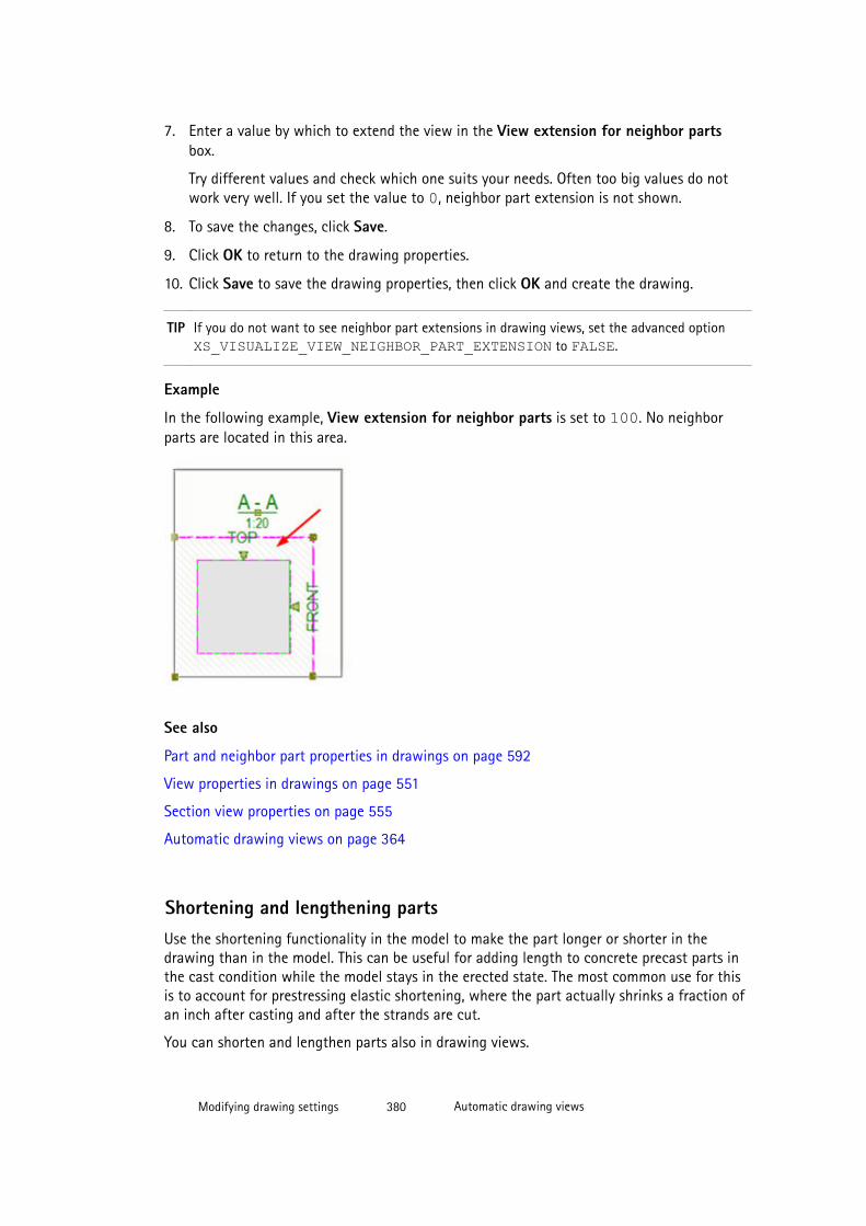
7. Enter a value by which to extend the view in the View extension for neighbor partsbox.
Try different values and check which one suits your needs. Often too big values do notwork very well. If you set the value to 0, neighbor part extension is not shown.
8. To save the changes, click Save.
9. Click OK to return to the drawing properties.
10. Click Save to save the drawing properties, then click OK and create the drawing.
TIP If you do not want to see neighbor part extensions in drawing views, set the advanced option XS_VISUALIZE_VIEW_NEIGHBOR_PART_EXTENSION to FALSE.
Example
In the following example, View extension for neighbor parts is set to 100. No neighborparts are located in this area.
See also
Part and neighbor part properties in drawings on page 592
View properties in drawings on page 551
Section view properties on page 555
Automatic drawing views on page 364
Shortening and lengthening partsUse the shortening functionality in the model to make the part longer or shorter in thedrawing than in the model. This can be useful for adding length to concrete precast parts inthe cast condition while the model stays in the erected state. The most common use for thisis to account for prestressing elastic shortening, where the part actually shrinks a fraction ofan inch after casting and after the strands are cut.
You can shorten and lengthen parts also in drawing views.
Modifying drawing settings 380 Automatic drawing views

See also
Shortening a part in the model on page 381
Lengthening a part in the model on page 381
Shortening parts in drawing views on page 382
Lengthening shortened parts in drawing views on page 384
Shortening parts view by view on page 204
Shortening a part in the model
To shorten a part in the model:
1. Double-click a part to open the part properties dialog box.
2. Go to the Deforming tab.
3. In the Shortening box, define the degree of shortening.
4. Click Modify.
When drawings are created, Tekla Structures decreases the true length of the part by thevalue defined in the Shortening box. Shortening is applied linearly along the length indrawings.
TIP To show the dimensions of the shortened part correctly in the drawings, set the settingUndeformed to Yes in drawing properties on the Attributes tab of the View creationproperties.
See also
Shortening and lengthening parts on page 380
Undeforming deformed parts in drawings on page 386
Lengthening a part in the modelTo have a concrete part lengthened in cast unit drawings, you must enter a negative value forshortening in the part properties dialog box.
To lengthen a part in drawings:
1. Double-click a part to open the part properties dialog box.
2. Go to the Deforming tab.
3. In the Shortening box, enter a negative value.
For example, -20 would result in a part that is cast 20 units longer than the part in themodel.
4. Click Modify.
Modifying drawing settings 381 Automatic drawing views
See also
Shortening and lengthening parts on page 380
Shortening parts in drawing views
If parts are quite large and do not include any important details, you can shorten them indrawing views. Parts are only cut in empty areas. If there is something important, forexample, a stiffener in the part, the part is not cut in that area, because that area is notconsidered empty.
To shorten parts:
1. Click Drawings & Reports --> Drawing Settings and select the drawing type.
2. Load the properties that you want to change.
3. Click View creation, select the view and the properties that you want to change, andclick View properties.
4. Go to the Attributes 2 tab.
5. In Cut parts, select one of the following:
• Yes to cut in both X and Y direction.
• Only in X direction
• Only in Y direction
6. In Minimum cut part length and Space between cut parts, select how to cut themiddle regions of the parts in drawing views.
The Minimum cut part length defines how long the part must at least be to getshortened. The length of the part must be at least twice the entered value.
The Space between cut parts defines the distance between cut parts on paper. Forexample, try 3.0 mm.
7. Set Cut skew parts to Yes to also cut skew parts in views.
8. To save the changes, click Save.
9. Click OK.
10. Click Save to save the drawing properties, then click OK and create the drawing.
Related advanced options
• You can show view shortening symbols in drawings by setting the advanced options XS_DRAW_VERTICAL_VIEW_SHORTENING_SYMBOLS_TO_PARTS and XS_DRAW_HORIZONTAL_VIEW_SHORTENING_SYMBOLS_TO_PARTS to TRUEthrough Tools --> Options --> Advanced Options --> Drawing Properties .
• You can also control the appearance of the view shortening symbol with the advancedoptions XS_SHORTENING_SYMBOL_COLOR,
Modifying drawing settings 382 Automatic drawing views
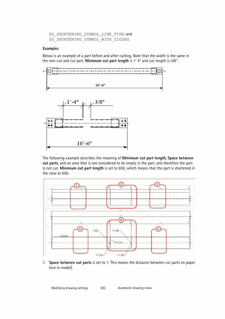
XS_SHORTENING_SYMBOL_LINE_TYPE, and XS_SHORTENING_SYMBOL_WITH_ZIGZAG.
Examples
Below is an example of a part before and after cutting. Note that the width is the same inthe non-cut and cut part. Minimum cut part length is 1' 4" and cut length is 3/8".
The following example describes the meaning of Minimum cut part length, Space betweencut parts, and an area that is not considered to be empty in the part, and therefore the partis not cut. Minimum cut part length is set to 650, which means that the part is shortened inthe view at 650.
1. Space between cut parts is set to 1. This means the distance between cut parts on paper(not in model).
Modifying drawing settings 383 Automatic drawing views
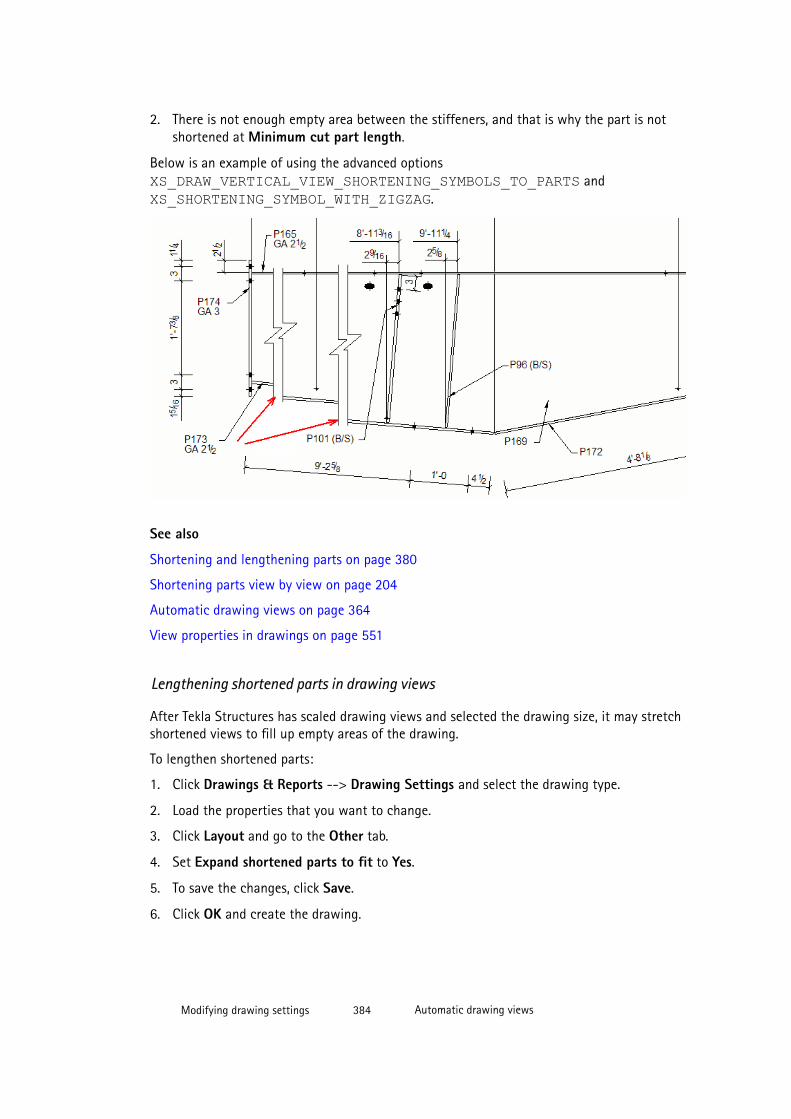
2. There is not enough empty area between the stiffeners, and that is why the part is notshortened at Minimum cut part length.
Below is an example of using the advanced options XS_DRAW_VERTICAL_VIEW_SHORTENING_SYMBOLS_TO_PARTS and XS_SHORTENING_SYMBOL_WITH_ZIGZAG.
See also
Shortening and lengthening parts on page 380
Shortening parts view by view on page 204
Automatic drawing views on page 364
View properties in drawings on page 551
Lengthening shortened parts in drawing views
After Tekla Structures has scaled drawing views and selected the drawing size, it may stretchshortened views to fill up empty areas of the drawing.
To lengthen shortened parts:
1. Click Drawings & Reports --> Drawing Settings and select the drawing type.
2. Load the properties that you want to change.
3. Click Layout and go to the Other tab.
4. Set Expand shortened parts to fit to Yes.
5. To save the changes, click Save.
6. Click OK and create the drawing.
Modifying drawing settings 384 Automatic drawing views
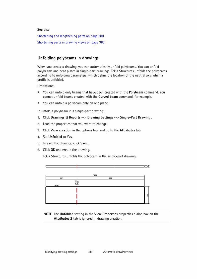
See also
Shortening and lengthening parts on page 380
Shortening parts in drawing views on page 382
Unfolding polybeams in drawings
When you create a drawing, you can automatically unfold polybeams. You can unfoldpolybeams and bent plates in single-part drawings. Tekla Structures unfolds the polybeamsaccording to unfolding parameters, which define the location of the neutral axis when aprofile is unfolded.
Limitations:
• You can unfold only beams that have been created with the Polybeam command. Youcannot unfold beams created with the Curved beam command, for example.
• You can unfold a polybeam only on one plane.
To unfold a polybeam in a single-part drawing:
1. Click Drawings & Reports --> Drawing Settings --> Single-Part Drawing .
2. Load the properties that you want to change.
3. Click View creation in the options tree and go to the Attributes tab.
4. Set Unfolded to Yes.
5. To save the changes, click Save.
6. Click OK and create the drawing.
Tekla Structures unfolds the polybeam in the single-part drawing.
NOTE The Unfolded setting in the View Properties properties dialog box on theAttributes 2 tab is ignored in drawing creation.
Modifying drawing settings 385 Automatic drawing views
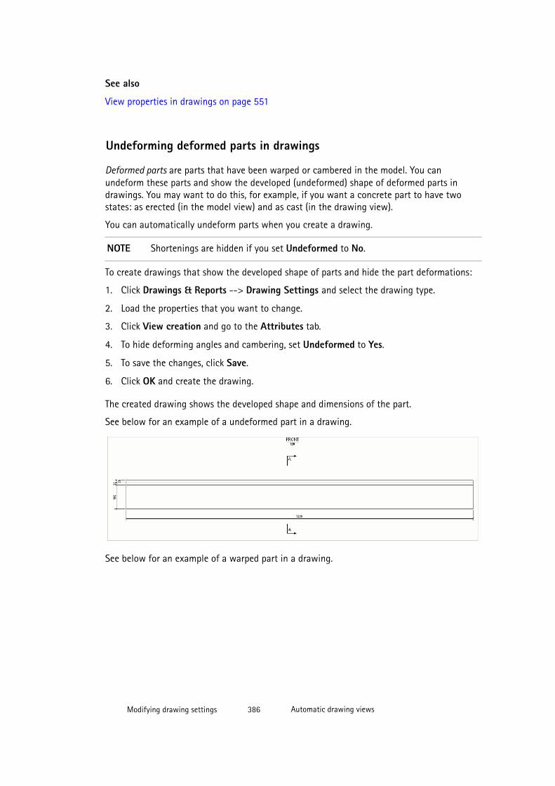
See also
View properties in drawings on page 551
Undeforming deformed parts in drawings
Deformed parts are parts that have been warped or cambered in the model. You canundeform these parts and show the developed (undeformed) shape of deformed parts indrawings. You may want to do this, for example, if you want a concrete part to have twostates: as erected (in the model view) and as cast (in the drawing view).
You can automatically undeform parts when you create a drawing.
NOTE Shortenings are hidden if you set Undeformed to No.
To create drawings that show the developed shape of parts and hide the part deformations:
1. Click Drawings & Reports --> Drawing Settings and select the drawing type.
2. Load the properties that you want to change.
3. Click View creation and go to the Attributes tab.
4. To hide deforming angles and cambering, set Undeformed to Yes.
5. To save the changes, click Save.
6. Click OK and create the drawing.
The created drawing shows the developed shape and dimensions of the part.
See below for an example of a undeformed part in a drawing.
See below for an example of a warped part in a drawing.
Modifying drawing settings 386 Automatic drawing views
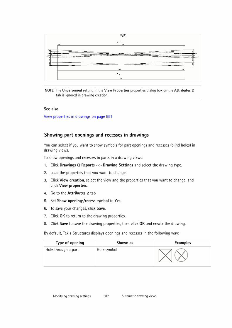
NOTE The Undeformed setting in the View Properties properties dialog box on the Attributes 2tab is ignored in drawing creation.
See also
View properties in drawings on page 551
Showing part openings and recesses in drawings
You can select if you want to show symbols for part openings and recesses (blind holes) indrawing views.
To show openings and recesses in parts in a drawing views:
1. Click Drawings & Reports --> Drawing Settings and select the drawing type.
2. Load the properties that you want to change.
3. Click View creation, select the view and the properties that you want to change, andclick View properties.
4. Go to the Attributes 2 tab.
5. Set Show openings/recess symbol to Yes.
6. To save your changes, click Save.
7. Click OK to return to the drawing properties.
8. Click Save to save the drawing properties, then click OK and create the drawing.
By default, Tekla Structures displays openings and recesses in the following way:
Type of opening Shown as Examples
Hole through a part Hole symbol
Modifying drawing settings 387 Automatic drawing views
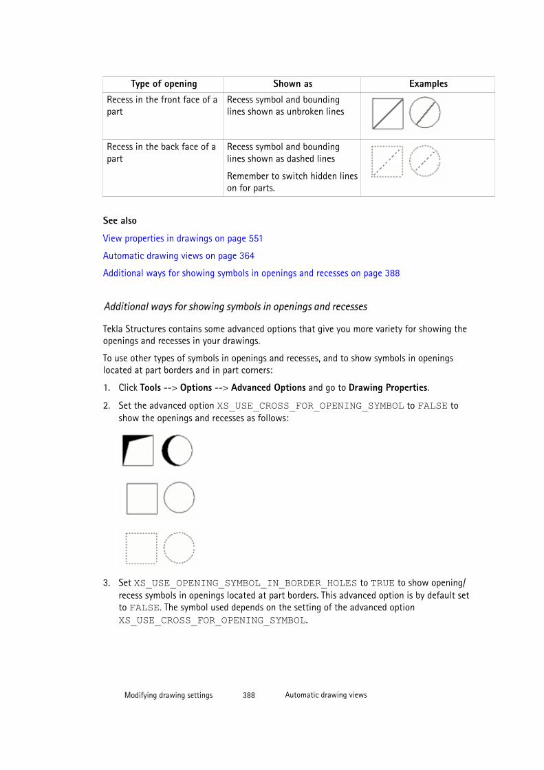
Type of opening Shown as Examples
Recess in the front face of apart
Recess symbol and boundinglines shown as unbroken lines
Recess in the back face of apart
Recess symbol and boundinglines shown as dashed lines
Remember to switch hidden lineson for parts.
See also
View properties in drawings on page 551
Automatic drawing views on page 364
Additional ways for showing symbols in openings and recesses on page 388
Additional ways for showing symbols in openings and recesses
Tekla Structures contains some advanced options that give you more variety for showing theopenings and recesses in your drawings.
To use other types of symbols in openings and recesses, and to show symbols in openingslocated at part borders and in part corners:
1. Click Tools --> Options --> Advanced Options and go to Drawing Properties.
2. Set the advanced option XS_USE_CROSS_FOR_OPENING_SYMBOL to FALSE toshow the openings and recesses as follows:
3. Set XS_USE_OPENING_SYMBOL_IN_BORDER_HOLES to TRUE to show opening/recess symbols in openings located at part borders. This advanced option is by default setto FALSE. The symbol used depends on the setting of the advanced option XS_USE_CROSS_FOR_OPENING_SYMBOL.
Modifying drawing settings 388 Automatic drawing views
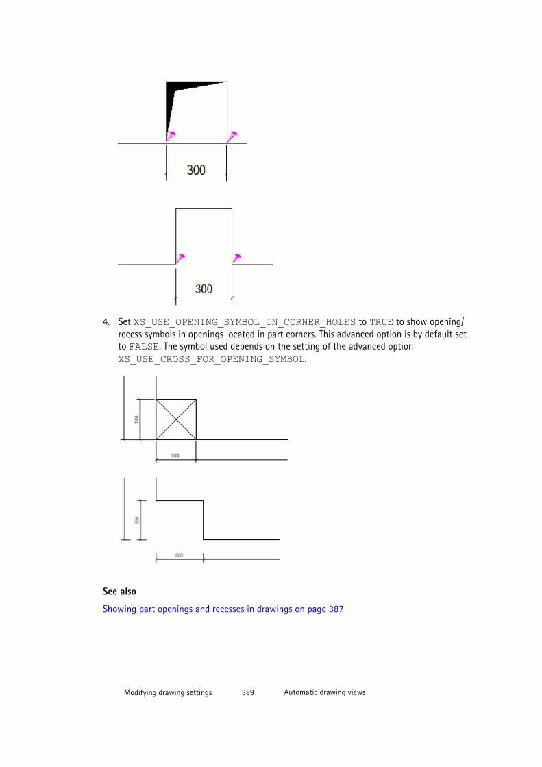
4. Set XS_USE_OPENING_SYMBOL_IN_CORNER_HOLES to TRUE to show opening/recess symbols in openings located in part corners. This advanced option is by default setto FALSE. The symbol used depends on the setting of the advanced option XS_USE_CROSS_FOR_OPENING_SYMBOL.
See also
Showing part openings and recesses in drawings on page 387
Modifying drawing settings 389 Automatic drawing views
Setting automatic section view properties
Properties for automatic section views need to be set in two places in drawing properties: inSection view, and in View creation --> View properties .
1. Click Drawings & Reports --> Drawing Settings and select the drawing type.
2. Load the properties that you want to change.
3. Click Section view.
4. On the Attributes tab, set values for options Section depth and Distance for combiningcuts:
• Section depth defines the positive and negative depth of the section view whensections are not combined. In an open drawing, you can adjust the section viewdepth also by dragging the view boundary.
• Distance for combining cuts defines the distance range for combining cut views.
• You can additionally control which section views get combined using the advancedoption XS_DRAWING_CUT_VIEW_COMPARISON_CRITERIA.
5. Still on the Attributes tab, set the direction of the Left section, Middle section andRight section to left or right.
6. Go to the Cutting line tab and set the section mark line length and offset (distancebetween the section mark and the section).
7. Go to the Section mark tab and modify the section mark settings:
a. Click the ... button next to A1 - A5 to open the Mark Contents dialog box.
b. Select the elements that you want to include in the mark.
c. If needed, select an element from the list and click Add frame and select the frameType and Color.
d. If needed, select an element from the list and select the text Color, Font and Height.
e. Go to the Position tab and select the side to show the text, the text position, thehorizontal and vertical offset, and the text rotation options.
f. Click OK to return to drawing properties.
8. Click View creation and add the section and end views you want to create.
9. In the View creation panel, select the view and the properties that you want to changeand click View Properties.
10. Adjust the scale, view label and view direction marks as required.
11. Click Save to save the view properties.
12. Click OK.
13. Repeat steps 9 - 12 for all the section and end views you create.
14. To save the changes, click Save.
Modifying drawing settings 390 Automatic drawing views
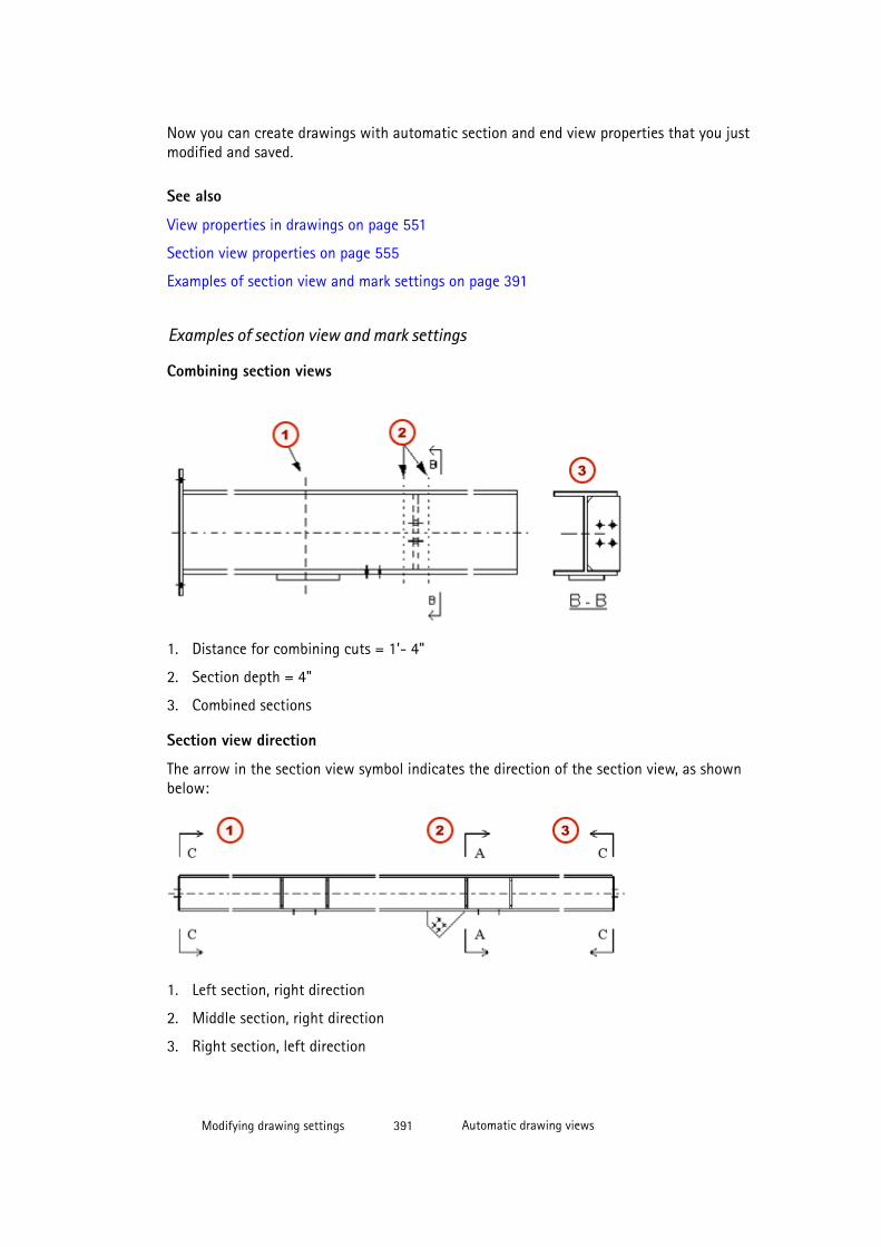
Now you can create drawings with automatic section and end view properties that you justmodified and saved.
See also
View properties in drawings on page 551
Section view properties on page 555
Examples of section view and mark settings on page 391
Examples of section view and mark settings
Combining section views
1. Distance for combining cuts = 1’- 4"
2. Section depth = 4"
3. Combined sections
Section view direction
The arrow in the section view symbol indicates the direction of the section view, as shownbelow:
1. Left section, right direction
2. Middle section, right direction
3. Right section, left direction
Modifying drawing settings 391 Automatic drawing views
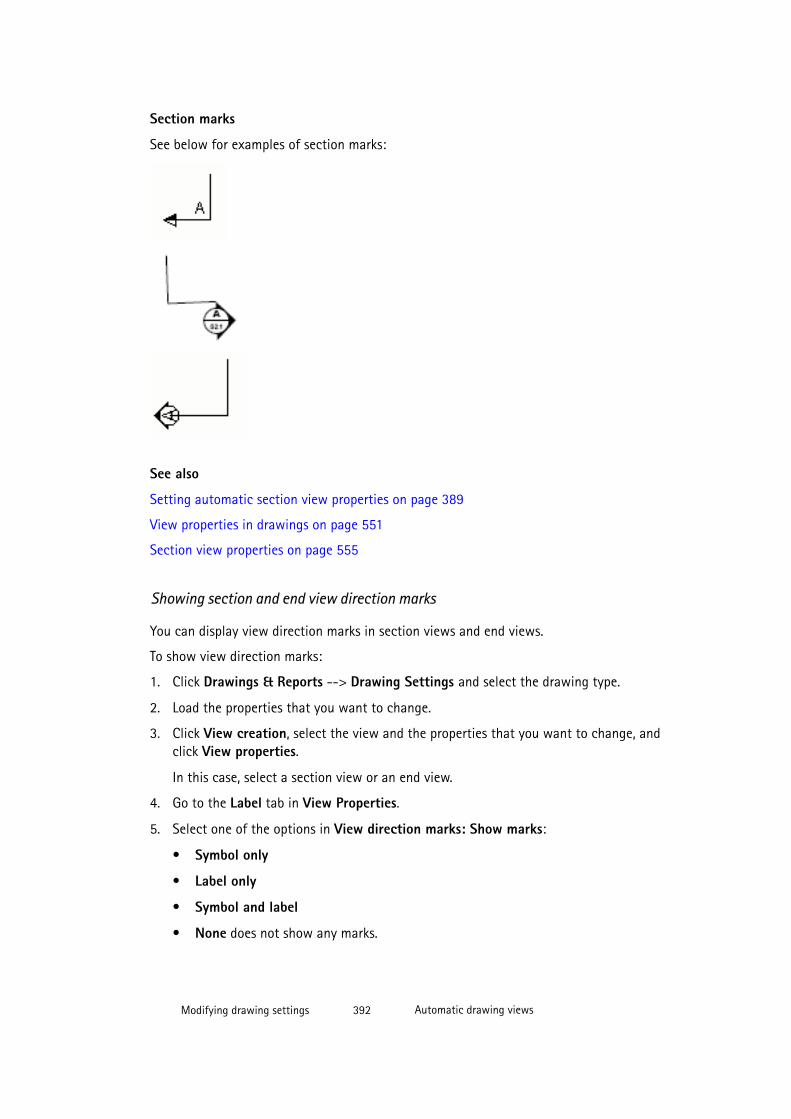
Section marks
See below for examples of section marks:
See also
Setting automatic section view properties on page 389
View properties in drawings on page 551
Section view properties on page 555
Showing section and end view direction marks
You can display view direction marks in section views and end views.
To show view direction marks:
1. Click Drawings & Reports --> Drawing Settings and select the drawing type.
2. Load the properties that you want to change.
3. Click View creation, select the view and the properties that you want to change, andclick View properties.
In this case, select a section view or an end view.
4. Go to the Label tab in View Properties.
5. Select one of the options in View direction marks: Show marks:
• Symbol only
• Label only
• Symbol and label
• None does not show any marks.
Modifying drawing settings 392 Automatic drawing views
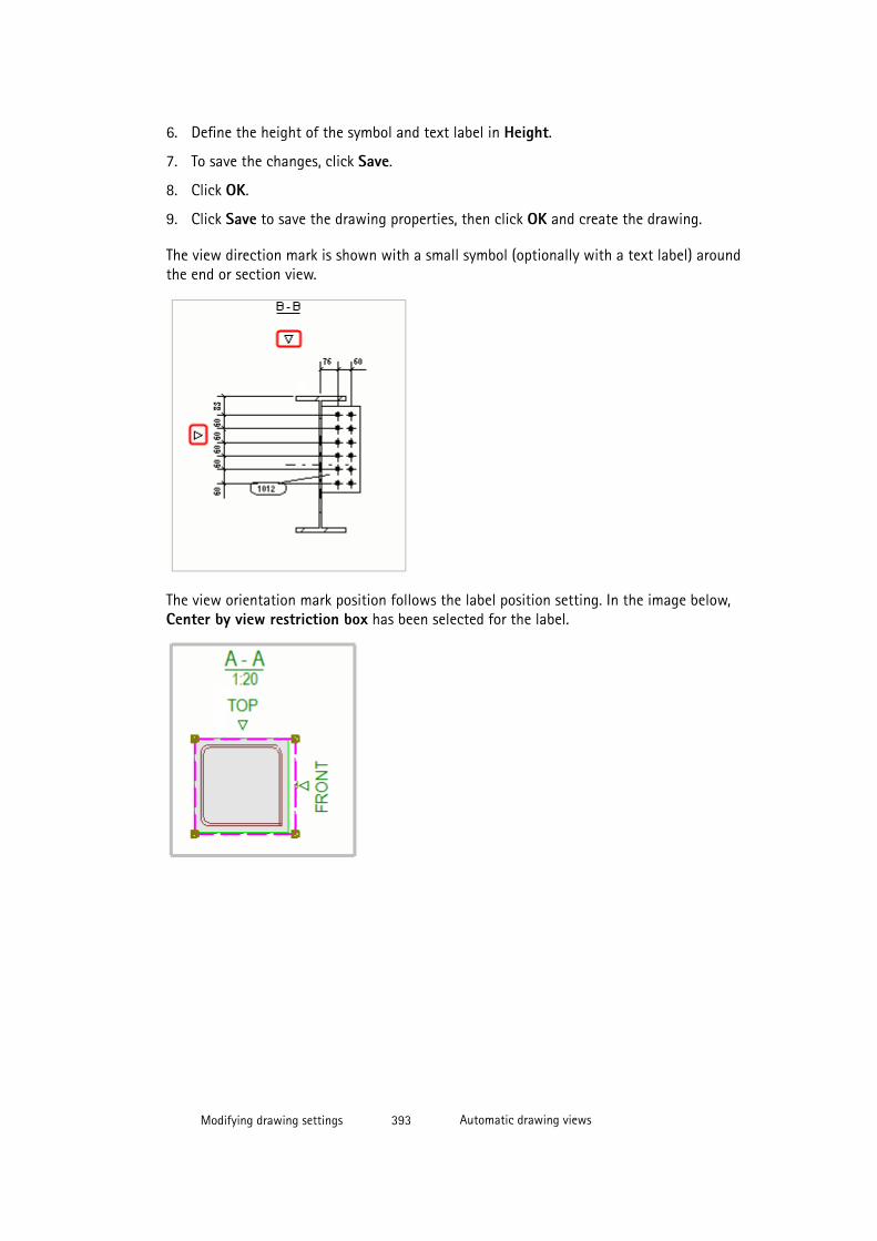
6. Define the height of the symbol and text label in Height.
7. To save the changes, click Save.
8. Click OK.
9. Click Save to save the drawing properties, then click OK and create the drawing.
The view direction mark is shown with a small symbol (optionally with a text label) aroundthe end or section view.
The view orientation mark position follows the label position setting. In the image below,Center by view restriction box has been selected for the label.
Modifying drawing settings 393 Automatic drawing views
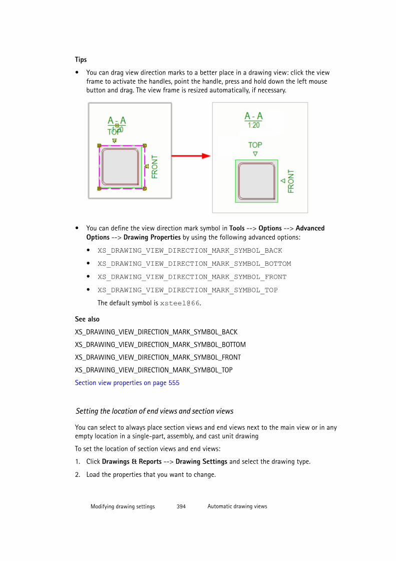
Tips
• You can drag view direction marks to a better place in a drawing view: click the viewframe to activate the handles, point the handle, press and hold down the left mousebutton and drag. The view frame is resized automatically, if necessary.
• You can define the view direction mark symbol in Tools --> Options --> AdvancedOptions --> Drawing Properties by using the following advanced options:
• XS_DRAWING_VIEW_DIRECTION_MARK_SYMBOL_BACK• XS_DRAWING_VIEW_DIRECTION_MARK_SYMBOL_BOTTOM• XS_DRAWING_VIEW_DIRECTION_MARK_SYMBOL_FRONT• XS_DRAWING_VIEW_DIRECTION_MARK_SYMBOL_TOP
The default symbol is xsteel@66.
See also
XS_DRAWING_VIEW_DIRECTION_MARK_SYMBOL_BACK
XS_DRAWING_VIEW_DIRECTION_MARK_SYMBOL_BOTTOM
XS_DRAWING_VIEW_DIRECTION_MARK_SYMBOL_FRONT
XS_DRAWING_VIEW_DIRECTION_MARK_SYMBOL_TOP
Section view properties on page 555
Setting the location of end views and section views
You can select to always place section views and end views next to the main view or in anyempty location in a single-part, assembly, and cast unit drawing
To set the location of section views and end views:
1. Click Drawings & Reports --> Drawing Settings and select the drawing type.
2. Load the properties that you want to change.
Modifying drawing settings 394 Automatic drawing views
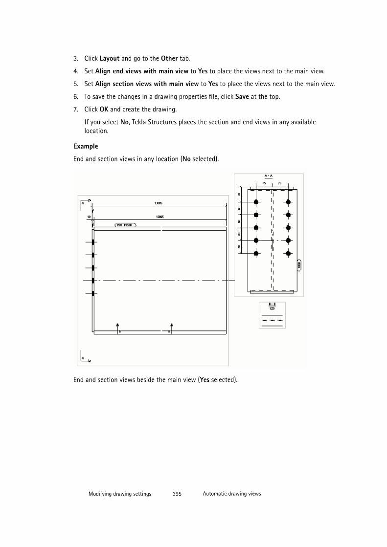
3. Click Layout and go to the Other tab.
4. Set Align end views with main view to Yes to place the views next to the main view.
5. Set Align section views with main view to Yes to place the views next to the main view.
6. To save the changes in a drawing properties file, click Save at the top.
7. Click OK and create the drawing.
If you select No, Tekla Structures places the section and end views in any availablelocation.
Example
End and section views in any location (No selected).
End and section views beside the main view (Yes selected).
Modifying drawing settings 395 Automatic drawing views
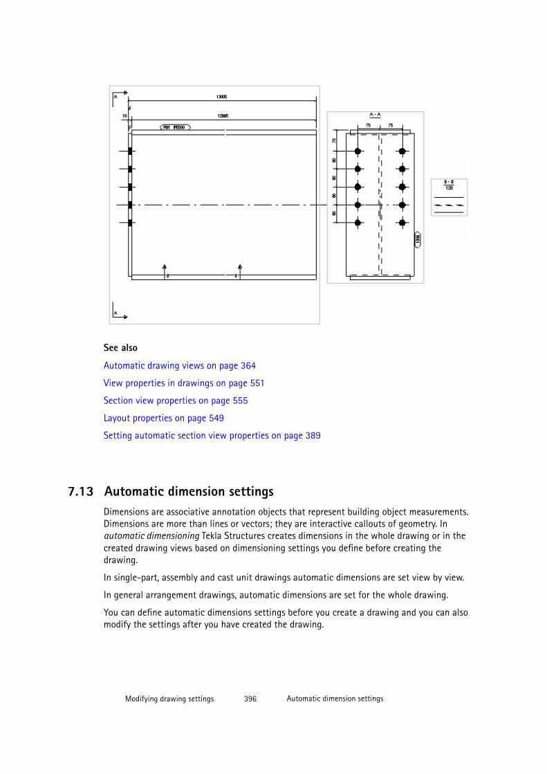
See also
Automatic drawing views on page 364
View properties in drawings on page 551
Section view properties on page 555
Layout properties on page 549
Setting automatic section view properties on page 389
7.13 Automatic dimension settingsDimensions are associative annotation objects that represent building object measurements.Dimensions are more than lines or vectors; they are interactive callouts of geometry. Inautomatic dimensioning Tekla Structures creates dimensions in the whole drawing or in thecreated drawing views based on dimensioning settings you define before creating thedrawing.
In single-part, assembly and cast unit drawings automatic dimensions are set view by view.
In general arrangement drawings, automatic dimensions are set for the whole drawing.
You can define automatic dimensions settings before you create a drawing and you can alsomodify the settings after you have created the drawing.
Modifying drawing settings 396 Automatic dimension settings
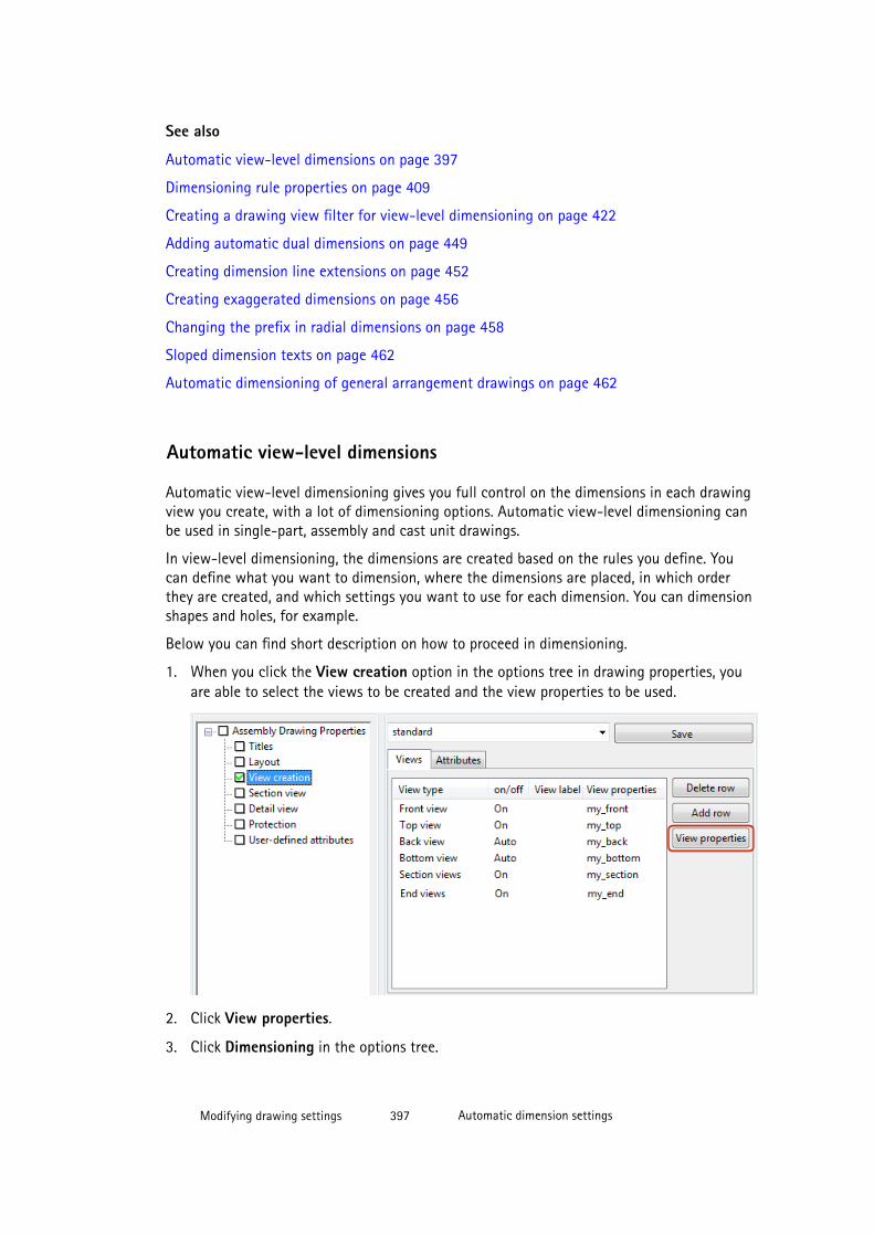
See also
Automatic view-level dimensions on page 397
Dimensioning rule properties on page 409
Creating a drawing view filter for view-level dimensioning on page 422
Adding automatic dual dimensions on page 449
Creating dimension line extensions on page 452
Creating exaggerated dimensions on page 456
Changing the prefix in radial dimensions on page 458
Sloped dimension texts on page 462
Automatic dimensioning of general arrangement drawings on page 462
Automatic view-level dimensions
Automatic view-level dimensioning gives you full control on the dimensions in each drawingview you create, with a lot of dimensioning options. Automatic view-level dimensioning canbe used in single-part, assembly and cast unit drawings.
In view-level dimensioning, the dimensions are created based on the rules you define. Youcan define what you want to dimension, where the dimensions are placed, in which orderthey are created, and which settings you want to use for each dimension. You can dimensionshapes and holes, for example.
Below you can find short description on how to proceed in dimensioning.
1. When you click the View creation option in the options tree in drawing properties, youare able to select the views to be created and the view properties to be used.
2. Click View properties.
3. Click Dimensioning in the options tree.
Modifying drawing settings 397 Automatic dimension settings
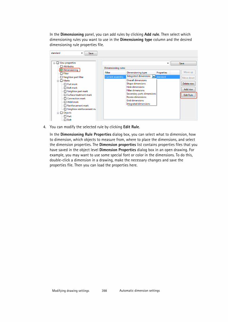
In the Dimensioning panel, you can add rules by clicking Add rule. Then select whichdimensioning rules you want to use in the Dimensioning type column and the desireddimensioning rule properties file.
4. You can modify the selected rule by clicking Edit Rule.
In the Dimensioning Rule Properties dialog box, you can select what to dimension, howto dimension, which objects to measure from, where to place the dimensions, and selectthe dimension properties. The Dimension properties list contains properties files that youhave saved in the object level Dimension Properties dialog box in an open drawing. Forexample, you may want to use some special font or color in the dimensions. To do this,double-click a dimension in a drawing, make the necessary changes and save theproperties file. Then you can load the properties here.
Modifying drawing settings 398 Automatic dimension settings

If you select Intergrated dimensions, the Dimensioning Properties dialog box isdisplayed. Make your changes to the settings on the tabs and save the properties filewith a unique name using Save as. You can also load dimension properties here as well.
Modifying drawing settings 399 Automatic dimension settings

5. When you have set the rule properties, give a name to the rules file and click Save as.
6. Click Close to return to the Dimensioning panel.
7. Ensure that you have selected correct dimensioning properties files for the dimensioningrules.
Modifying drawing settings 400 Automatic dimension settings
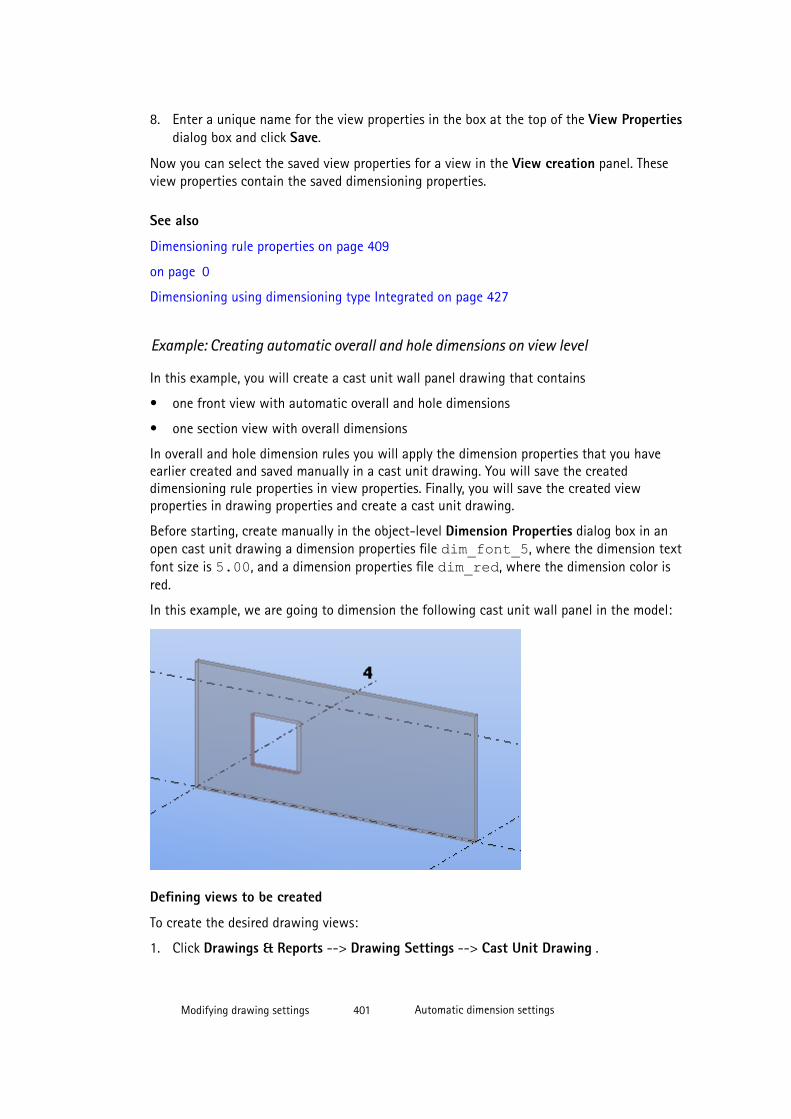
8. Enter a unique name for the view properties in the box at the top of the View Propertiesdialog box and click Save.
Now you can select the saved view properties for a view in the View creation panel. Theseview properties contain the saved dimensioning properties.
See also
Dimensioning rule properties on page 409
on page 0
Dimensioning using dimensioning type Integrated on page 427
Example: Creating automatic overall and hole dimensions on view level
In this example, you will create a cast unit wall panel drawing that contains
• one front view with automatic overall and hole dimensions
• one section view with overall dimensions
In overall and hole dimension rules you will apply the dimension properties that you haveearlier created and saved manually in a cast unit drawing. You will save the createddimensioning rule properties in view properties. Finally, you will save the created viewproperties in drawing properties and create a cast unit drawing.
Before starting, create manually in the object-level Dimension Properties dialog box in anopen cast unit drawing a dimension properties file dim_font_5, where the dimension textfont size is 5.00, and a dimension properties file dim_red, where the dimension color isred.
In this example, we are going to dimension the following cast unit wall panel in the model:
Defining views to be created
To create the desired drawing views:
1. Click Drawings & Reports --> Drawing Settings --> Cast Unit Drawing .
Modifying drawing settings 401 Automatic dimension settings
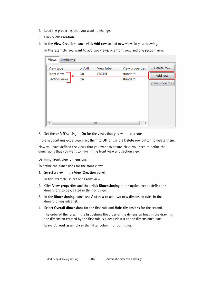
2. Load the properties that you want to change.
3. Click View Creation.
4. In the View Creation panel, click Add row to add new views in your drawing.
In this example, you want to add two views, one front view and one section view.
5. Set the on/off setting to On for the views that you want to create.
If the list contains extra views, set them to Off or use the Delete row button to delete them.
Now you have defined the views that you want to create. Next, you need to define thedimensions that you want to have in the front view and section view.
Defining front view dimensions
To define the dimensions for the front view:
1. Select a view in the View Creation panel.
In this example, select one Front view.
2. Click View properties and then click Dimensioning in the option tree to define thedimensions to be created in the front view.
3. In the Dimensioning panel, use Add row to add two new dimension rules in thedimensioning rules list.
4. Select Overall dimensions for the first rule and Hole dimensions for the second.
The order of the rules in the list defines the order of the dimension lines in the drawing:the dimension created by the first rule is placed closest to the dimensioned part.
Leave Current assembly in the Filter column for both rules.
Modifying drawing settings 402 Automatic dimension settings
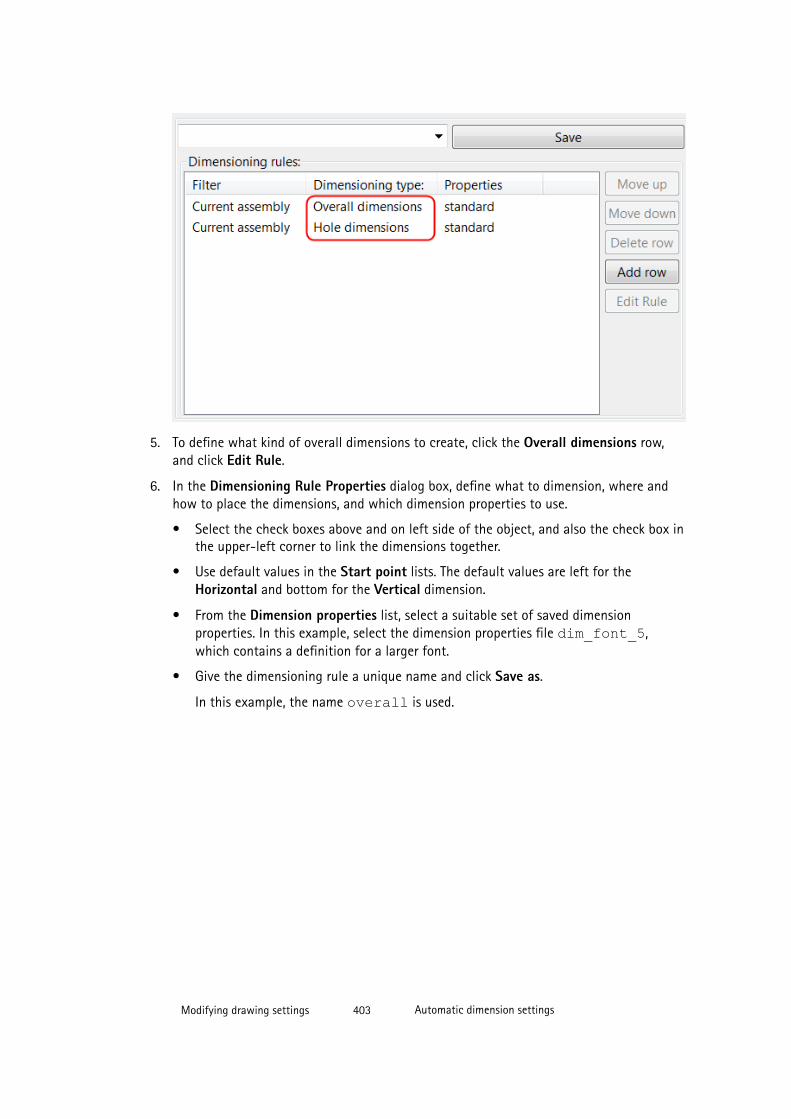
5. To define what kind of overall dimensions to create, click the Overall dimensions row,and click Edit Rule.
6. In the Dimensioning Rule Properties dialog box, define what to dimension, where andhow to place the dimensions, and which dimension properties to use.
• Select the check boxes above and on left side of the object, and also the check box inthe upper-left corner to link the dimensions together.
• Use default values in the Start point lists. The default values are left for theHorizontal and bottom for the Vertical dimension.
• From the Dimension properties list, select a suitable set of saved dimensionproperties. In this example, select the dimension properties file dim_font_5,which contains a definition for a larger font.
• Give the dimensioning rule a unique name and click Save as.
In this example, the name overall is used.
Modifying drawing settings 403 Automatic dimension settings
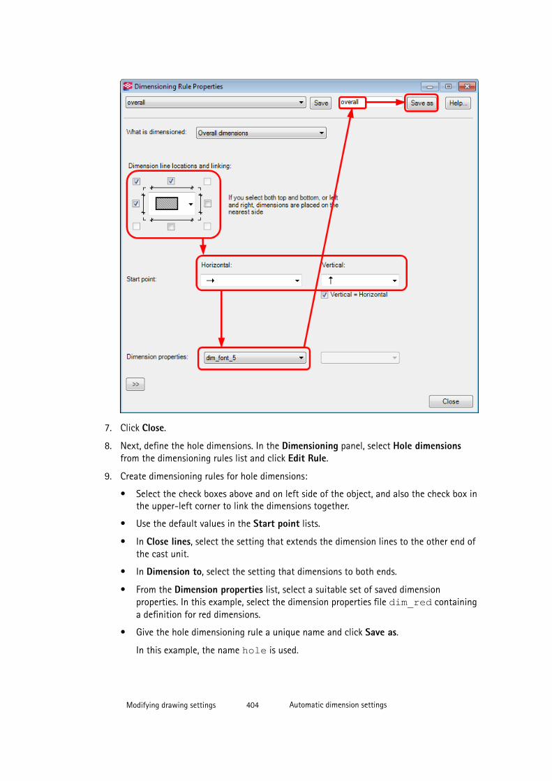
7. Click Close.
8. Next, define the hole dimensions. In the Dimensioning panel, select Hole dimensionsfrom the dimensioning rules list and click Edit Rule.
9. Create dimensioning rules for hole dimensions:
• Select the check boxes above and on left side of the object, and also the check box inthe upper-left corner to link the dimensions together.
• Use the default values in the Start point lists.
• In Close lines, select the setting that extends the dimension lines to the other end ofthe cast unit.
• In Dimension to, select the setting that dimensions to both ends.
• From the Dimension properties list, select a suitable set of saved dimensionproperties. In this example, select the dimension properties file dim_red containinga definition for red dimensions.
• Give the hole dimensioning rule a unique name and click Save as.
In this example, the name hole is used.
Modifying drawing settings 404 Automatic dimension settings
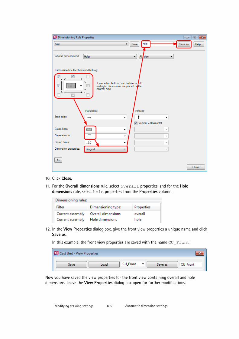
10. Click Close.
11. For the Overall dimensions rule, select overall properties, and for the Holedimensions rule, select hole properties from the Properties column.
12. In the View Properties dialog box, give the front view properties a unique name and clickSave as.
In this example, the front view properties are saved with the name CU_Front.
Now you have saved the view properties for the front view containing overall and holedimensions. Leave the View Properties dialog box open for further modifications.
Modifying drawing settings 405 Automatic dimension settings

Defining section view dimensions
Also a section view is needed in the cast unit drawing, because you want to show the wallthickness. Next, you will create overall dimensions for the section view.
1. In the View Creation panel, select the Section views row and click View properties.
2. Load the view properties file CU_Front.
You can start creating new view properties on the basis of already existing viewproperties.
3. Click Dimensioning in the options tree.
4. In the Dimensioning panel, delete the unnecessary hole dimension rule by clicking theHole dimensions row and Delete row.
You will only need the overall dimensions in the section view.
5. Click the Overall dimensions row and click Edit Rule.
6. Create a dimensioning rule for the overall dimensions in the section view:
• Select the check box below the object only, because you only want to show thethickness.
• Select the same dimension properties as for the overall dimensions in the front view,because you want to show the dimension text with a little bit larger font:dim_font_5.
• Give the rule a unique name and click Save as.
In this example, the name thickness is used.
Modifying drawing settings 406 Automatic dimension settings
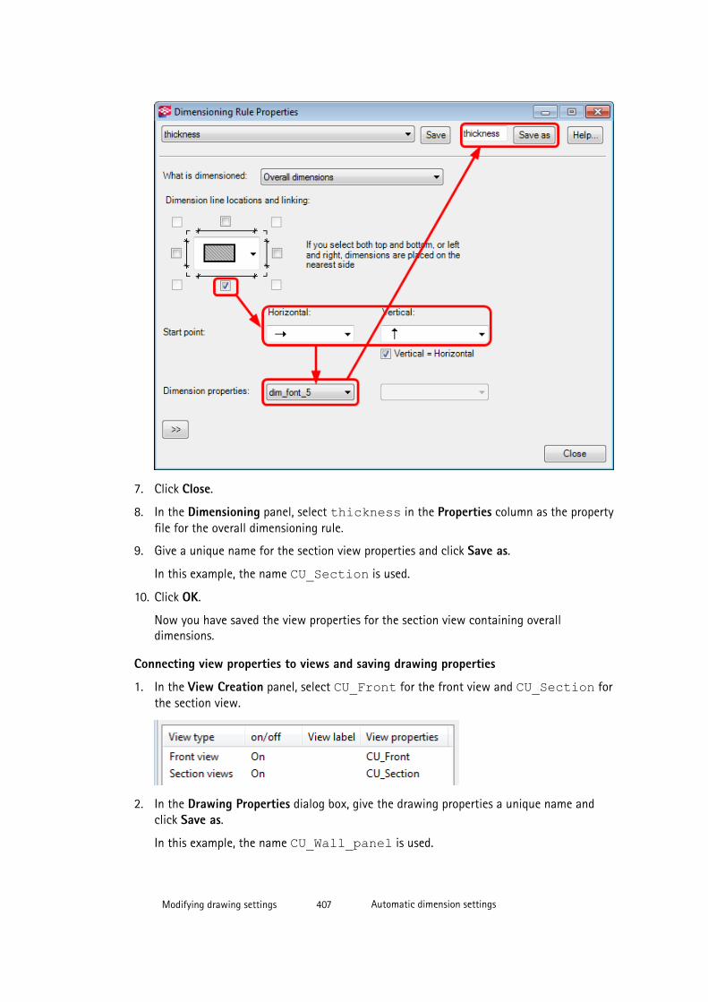
7. Click Close.
8. In the Dimensioning panel, select thickness in the Properties column as the propertyfile for the overall dimensioning rule.
9. Give a unique name for the section view properties and click Save as.
In this example, the name CU_Section is used.
10. Click OK.
Now you have saved the view properties for the section view containing overalldimensions.
Connecting view properties to views and saving drawing properties
1. In the View Creation panel, select CU_Front for the front view and CU_Section forthe section view.
2. In the Drawing Properties dialog box, give the drawing properties a unique name andclick Save as.
In this example, the name CU_Wall_panel is used.
Modifying drawing settings 407 Automatic dimension settings
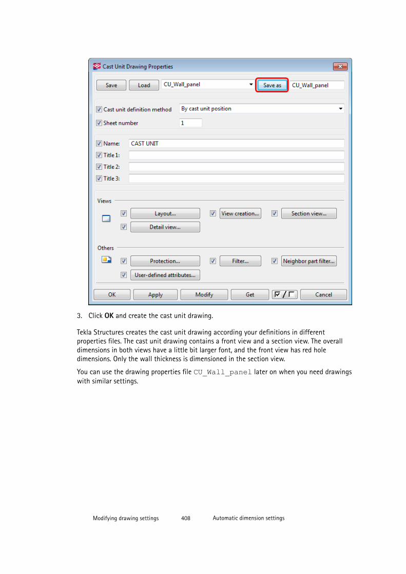
3. Click OK and create the cast unit drawing.
Tekla Structures creates the cast unit drawing according your definitions in differentproperties files. The cast unit drawing contains a front view and a section view. The overalldimensions in both views have a little bit larger font, and the front view has red holedimensions. Only the wall thickness is dimensioned in the section view.
You can use the drawing properties file CU_Wall_panel later on when you need drawingswith similar settings.
Modifying drawing settings 408 Automatic dimension settings
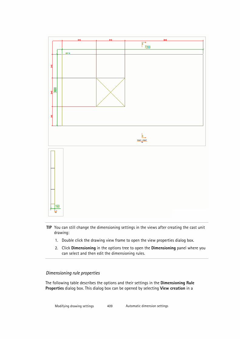
TIP You can still change the dimensioning settings in the views after creating the cast unitdrawing:
1. Double click the drawing view frame to open the view properties dialog box.
2. Click Dimensioning in the options tree to open the Dimensioning panel where youcan select and then edit the dimensioning rules.
Dimensioning rule properties
The following table describes the options and their settings in the Dimensioning RuleProperties dialog box. This dialog box can be opened by selecting View creation in a
Modifying drawing settings 409 Automatic dimension settings
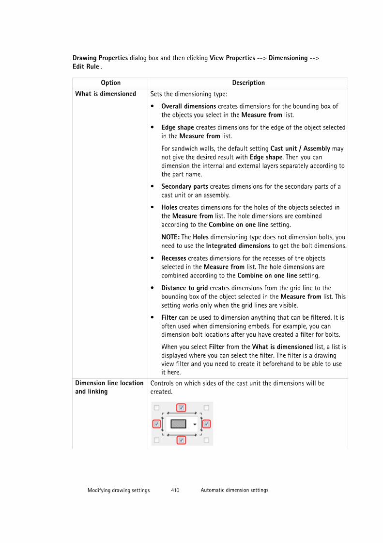
Drawing Properties dialog box and then clicking View Properties --> Dimensioning -->Edit Rule .
Option DescriptionWhat is dimensioned Sets the dimensioning type:
• Overall dimensions creates dimensions for the bounding box ofthe objects you select in the Measure from list.
• Edge shape creates dimensions for the edge of the object selectedin the Measure from list.
For sandwich walls, the default setting Cast unit / Assembly maynot give the desired result with Edge shape. Then you candimension the internal and external layers separately according tothe part name.
• Secondary parts creates dimensions for the secondary parts of acast unit or an assembly.
• Holes creates dimensions for the holes of the objects selected inthe Measure from list. The hole dimensions are combinedaccording to the Combine on one line setting.
NOTE: The Holes dimensioning type does not dimension bolts, youneed to use the Integrated dimensions to get the bolt dimensions.
• Recesses creates dimensions for the recesses of the objectsselected in the Measure from list. The hole dimensions arecombined according to the Combine on one line setting.
• Distance to grid creates dimensions from the grid line to thebounding box of the object selected in the Measure from list. Thissetting works only when the grid lines are visible.
• Filter can be used to dimension anything that can be filtered. It isoften used when dimensioning embeds. For example, you candimension bolt locations after you have created a filter for bolts.
When you select Filter from the What is dimensioned list, a list isdisplayed where you can select the filter. The filter is a drawingview filter and you need to create it beforehand to be able to useit here.
Dimension line locationand linking
Controls on which sides of the cast unit the dimensions will becreated.
Modifying drawing settings 410 Automatic dimension settings
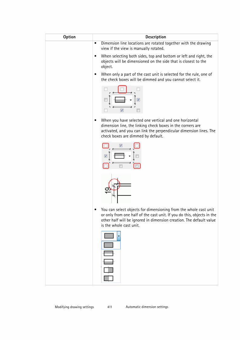
Option Description• Dimension line locations are rotated together with the drawing
view if the view is manually rotated.
• When selecting both sides, top and bottom or left and right, theobjects will be dimensioned on the side that is closest to theobject.
• When only a part of the cast unit is selected for the rule, one ofthe check boxes will be dimmed and you cannot select it.
• When you have selected one vertical and one horizontaldimension line, the linking check boxes in the corners areactivated, and you can link the perpendicular dimension lines. Thecheck boxes are dimmed by default.
• You can select objects for dimensioning from the whole cast unitor only from one half of the cast unit. If you do this, objects in theother half will be ignored in dimension creation. The default valueis the whole cast unit.
Modifying drawing settings 411 Automatic dimension settings
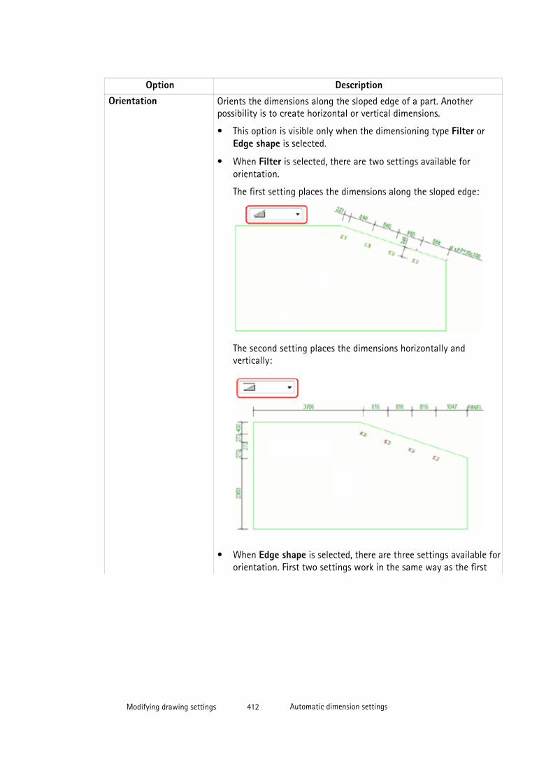
Option DescriptionOrientation Orients the dimensions along the sloped edge of a part. Another
possibility is to create horizontal or vertical dimensions.
• This option is visible only when the dimensioning type Filter orEdge shape is selected.
• When Filter is selected, there are two settings available fororientation.
The first setting places the dimensions along the sloped edge:
The second setting places the dimensions horizontally andvertically:
• When Edge shape is selected, there are three settings available fororientation. First two settings work in the same way as the first
Modifying drawing settings 412 Automatic dimension settings
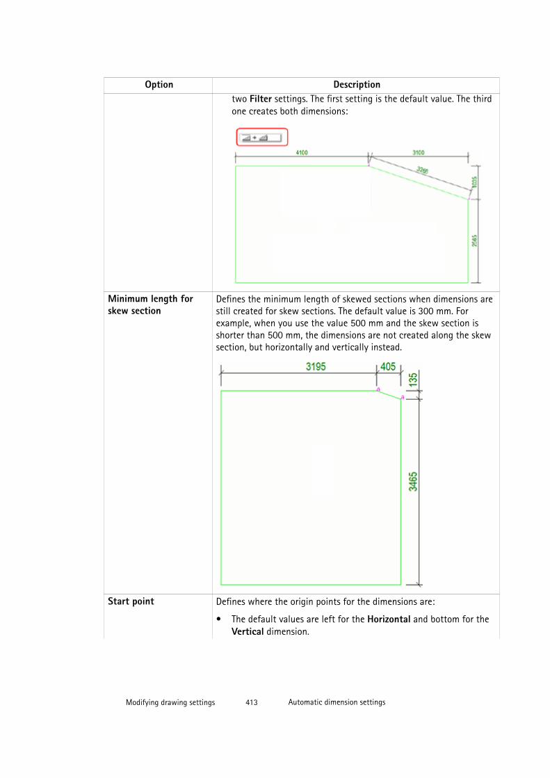
Option Descriptiontwo Filter settings. The first setting is the default value. The thirdone creates both dimensions:
Minimum length forskew section
Defines the minimum length of skewed sections when dimensions arestill created for skew sections. The default value is 300 mm. Forexample, when you use the value 500 mm and the skew section isshorter than 500 mm, the dimensions are not created along the skewsection, but horizontally and vertically instead.
Start point Defines where the origin points for the dimensions are:
• The default values are left for the Horizontal and bottom for theVertical dimension.
Modifying drawing settings 413 Automatic dimension settings
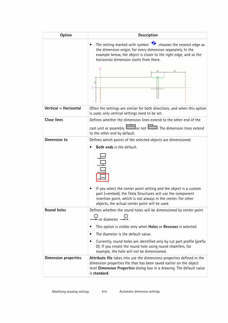
Option Description
• The setting marked with symbol chooses the nearest edge asthe dimension origin, for every dimension separately. In theexample below, the object is closer to the right edge, and so thehorizontal dimension starts from there.
Vertical = Horizontal Often the settings are similar for both directions, and when this optionis used, only vertical settings need to be set.
Close lines Defines whether the dimension lines extend to the other end of the
cast unit or assembly or not . The dimension lines extendto the other end by default.
Dimension to Defines which points of the selected objects are dimensioned:
• Both ends is the default.
• If you select the center point setting and the object is a custompart (=embed), the Tekla Structures will use the componentinsertion point, which is not always in the center. For otherobjects, the actual center point will be used.
Round holes Defines whether the round holes will be dimensioned by center point
or diameter :
• This option is visible only when Holes or Recesses is selected.
• The diameter is the default value.
• Currently, round holes are identified only by cut part profile (prefixD). If you create the round hole using round chamfers, forexample, the hole will not be dimensioned.
Dimension properties Attribute file takes into use the dimensions properties defined in thedimension properties file that has been saved earlier on the objectlevel Dimension Properties dialog box in a drawing. The default valueis standard.
Modifying drawing settings 414 Automatic dimension settings

Option DescriptionMeasure from Defines the objects that will be used as the origin point for the
dimensions. The available settings are:
• Cast unit/Assembly: This is the default value. If you select thissetting, you have three more settings available:
• Only concrete/steel parts: For a cast unit, only concrete partsare used, and for steel only steel parts.
• All parts
• All parts and rebars
• Main part: This setting uses cast unit or assembly main part.
• Part name: If you select Part name, you can define the part name.
• Filter: If you select Filter, you can use a predefined filter forselecting the objects that you want to use as dimension originpoints.
• Current part: Select Current part when you are dimensioning asingle part.
Combine on one line Creates a rule based on a filter, for example, for embeds (EB_*), andthen groups the embeds according to the main part name, so thatembeds with different names will get their own dimension lines. Thefiltered object can be a part, a reinforcing bar or an assembly. Theavailable settings are:
• All objects (default)
• By name
• By position number
• No
When Holes or Recesses is selected, the Combine on one line optionchanges to display suitable settings for holes or recesses. The availablesettings are:
• All holes (default)
• Any holes of the same size
• By cut part name
• NoCombine only objectsthat have the same X orY coordinate
Combines only the dimensions of objects that are on the samehorizontal or vertical line. By default, this options is not selected.
Tolerance The tolerance is the maximum distance between objects when TeklaStructures still considers the objects to be on the same line. 50 mm isthe default value.
Modifying drawing settings 415 Automatic dimension settings

Option DescriptionPreferred combiningdirection
Sets the preferred direction for combining dimensions if an object canbe combined both in horizontal and in vertical direction. X is thedefault value.
Do not createdimensions shorter than
Defines the minimum length of the dimensions for Tekla Structures tocreate them. 0 is the default value, which means that all dimensionsare created.
Do not dimension holessmaller than
Defines the minimum diameter for the holes for Tekla Structures tocreate the dimensions.
With this option you can prevent the creation of dimensions for smallholes. The distance is the shortest dimension of a hole. If anydimension of the hole is larger than the given value, the hole will bedimensioned in all directions. For example, with value 40, arectangular hole of 80*30 will get both dimensions 80 and 30. Defaultvalue is 0, which means that all dimensions are created.
Component objects Defines how component objects are dimensioned:
• By reference points (default) places the dimensioning point tothe first insertion point of the component. Only one dimension willbe created for each component regardless of the number of partsinside the components.
• As secondary objects creates separate dimensions for each partinside the component.
See also
on page 0
Creating a drawing view filter for view-level dimensioning on page 422
Dimension and dimensioning properties on page 556
Examples: Dimensions created with view-level dimensioning
See below for examples of dimensions created with different settings in the DimensioningRule Properties dialog box.
Overall dimensions
Modifying drawing settings 416 Automatic dimension settings
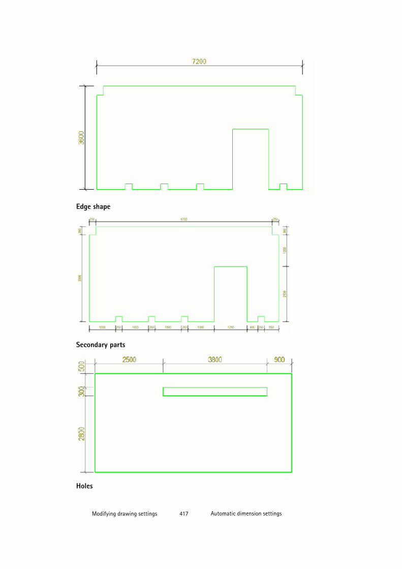
Edge shape
Secondary parts
Holes
Modifying drawing settings 417 Automatic dimension settings
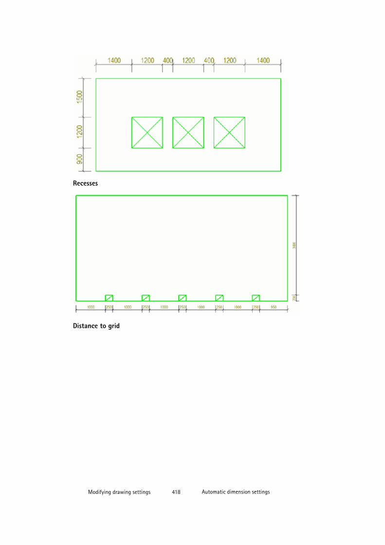
Recesses
Distance to grid
Modifying drawing settings 418 Automatic dimension settings
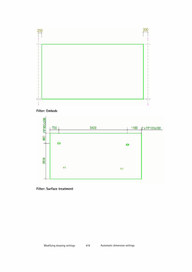
Filter: Embeds
Filter: Surface treatment
Modifying drawing settings 419 Automatic dimension settings
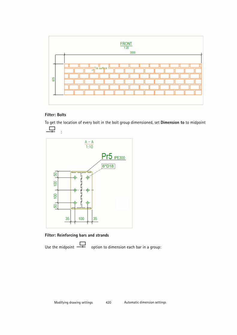
Filter: Bolts
To get the location of every bolt in the bolt group dimensioned, set Dimension to to midpoint
:
Filter: Reinforcing bars and strands
Use the midpoint option to dimension each bar in a group:
Modifying drawing settings 420 Automatic dimension settings

Start point and end point option will dimension the first and the last reinforcing bar ina group:
If you want to have separate dimension lines for reinforcing bars that are not of the samesize, set the Combine on one line to By position number:
To make the rule creation easier, the midpoint setting of the Dimension to option works sothat it will create dimensions to start point and end point of the reinforcing bars that areparallel to the view plane:
Modifying drawing settings 421 Automatic dimension settings
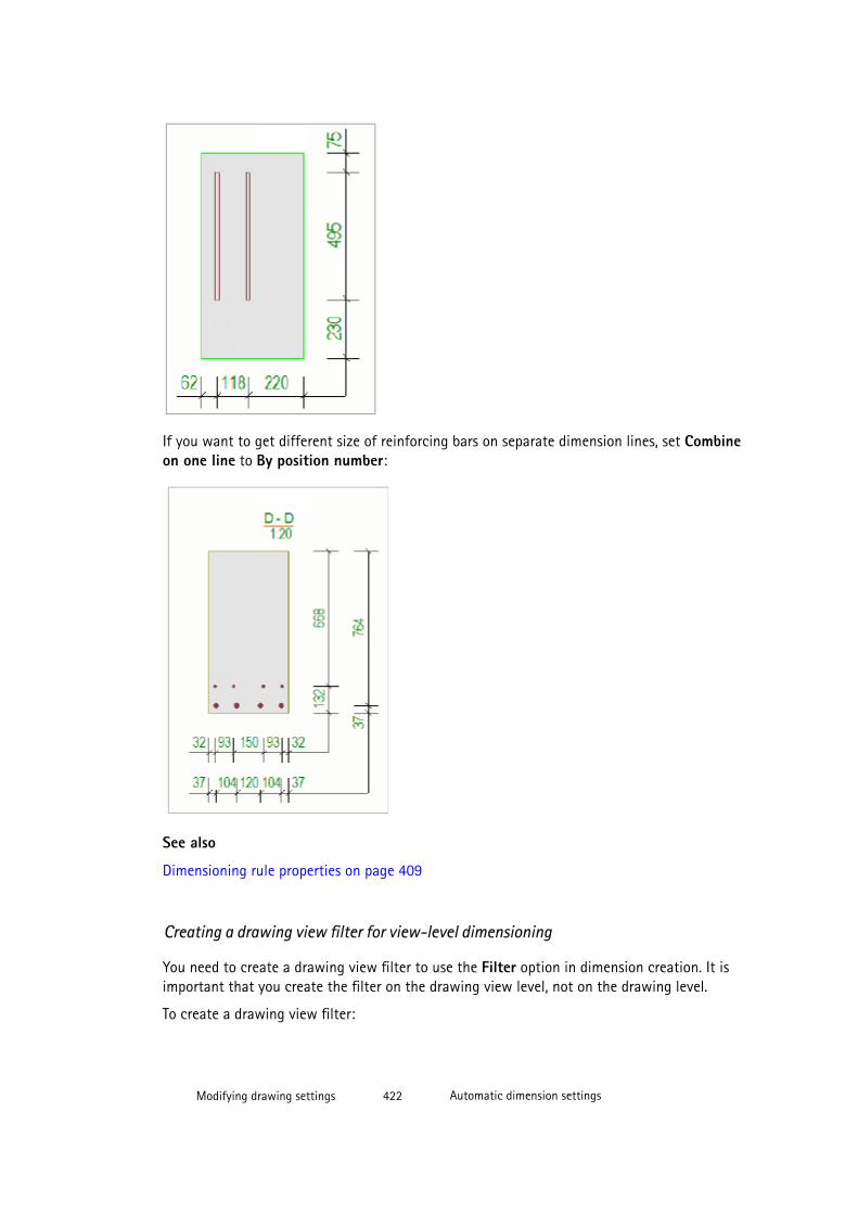
If you want to get different size of reinforcing bars on separate dimension lines, set Combineon one line to By position number:
See also
Dimensioning rule properties on page 409
Creating a drawing view filter for view-level dimensioning
You need to create a drawing view filter to use the Filter option in dimension creation. It isimportant that you create the filter on the drawing view level, not on the drawing level.
To create a drawing view filter:
Modifying drawing settings 422 Automatic dimension settings
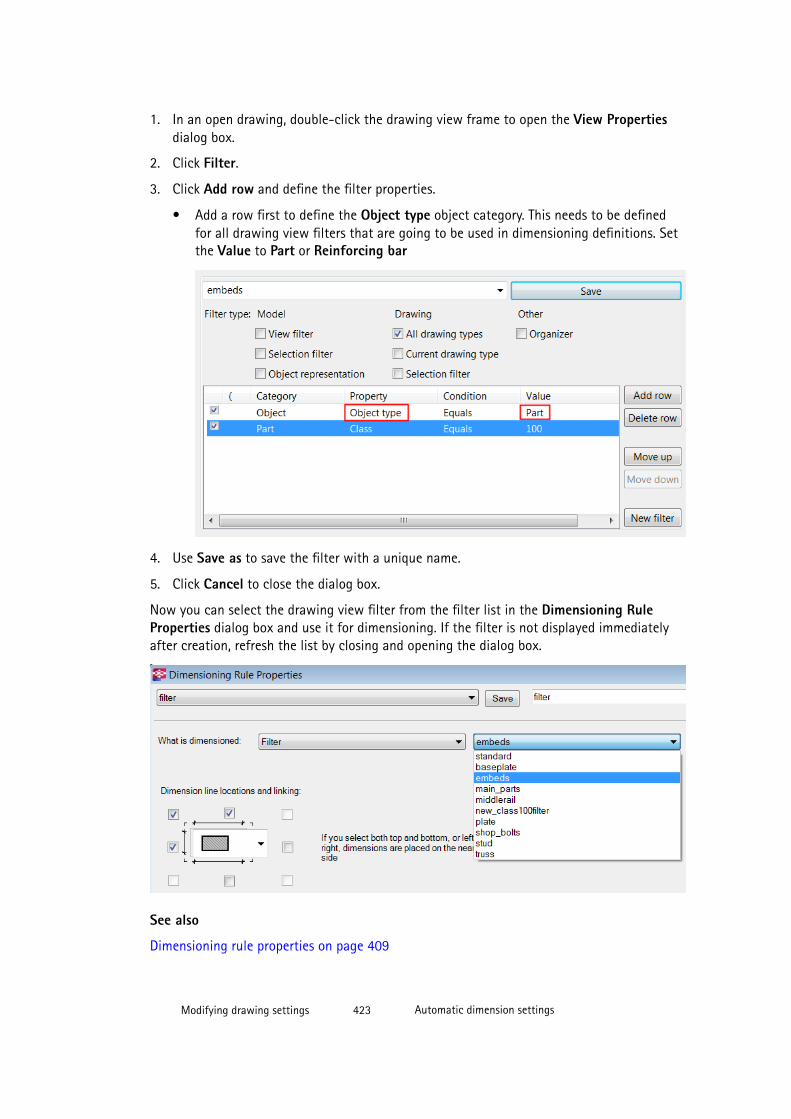
1. In an open drawing, double-click the drawing view frame to open the View Propertiesdialog box.
2. Click Filter.
3. Click Add row and define the filter properties.
• Add a row first to define the Object type object category. This needs to be definedfor all drawing view filters that are going to be used in dimensioning definitions. Setthe Value to Part or Reinforcing bar
4. Use Save as to save the filter with a unique name.
5. Click Cancel to close the dialog box.
Now you can select the drawing view filter from the filter list in the Dimensioning RuleProperties dialog box and use it for dimensioning. If the filter is not displayed immediatelyafter creation, refresh the list by closing and opening the dialog box.
See also
Dimensioning rule properties on page 409
Modifying drawing settings 423 Automatic dimension settings

Examples: Dimensions created with view-level dimensioning on page 416
Creating a filter for holes or recesses on page 424
Creating a filter for the main part of an assembly on page 425
Creating an exclude filter for dimension tag on page 426
Creating an exclude filter for stirrups in section views on page 426
Creating a filter for holes or recesses
You can create a filter for cut parts. The filter must be created in the modeling mode (not indrawing mode).
1. Click Edit --> Selection Filter .
2. Add the first row:
• Select Object as category, Object type as property and Equals as condition.
• To fill 11 in the value, use Select from model, and select a cut part.
3. Add the second row:
• Select Template as category, enter NAME in uppercase as property and select Equalsas condition.
• Enter the name of the template as the value.
4. Select check boxes Selection filter and All drawing types.
5. Save the filter with a unique name using Save as.
Modifying drawing settings 424 Automatic dimension settings
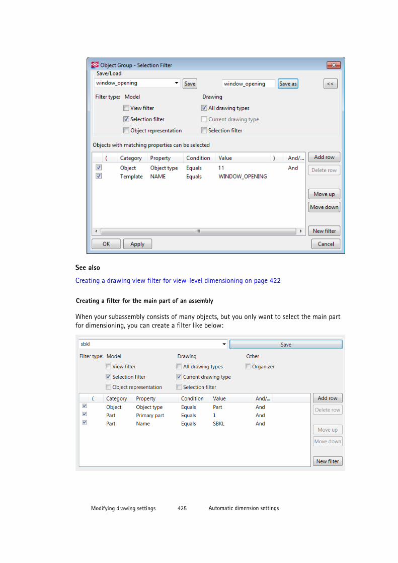
See also
Creating a drawing view filter for view-level dimensioning on page 422
Creating a filter for the main part of an assembly
When your subassembly consists of many objects, but you only want to select the main partfor dimensioning, you can create a filter like below:
Modifying drawing settings 425 Automatic dimension settings

See also
Creating a drawing view filter for view-level dimensioning on page 422
Creating an exclude filter for dimension tag
Often several objects need to be excluded from dimension tag content. With the examplefilter shown below it is possible to exclude everything else from the tag content, except cutparts that have the name ‘HVAC’.
See also
Creating a drawing view filter for view-level dimensioning on page 422
Creating an exclude filter for stirrups in section views
The view-based dimensioning currently dimensions reinforcing bar polygon points along thecenter line of the reinforcing bar. Below is an example of a stirrup in section view. In somecases, the resulting dimensions are created similarly regardless of the hook type.
Modifying drawing settings 426 Automatic dimension settings
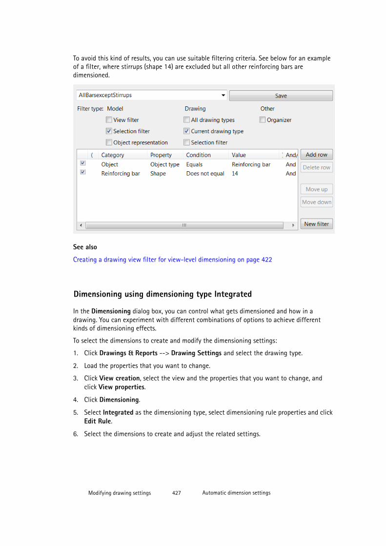
To avoid this kind of results, you can use suitable filtering criteria. See below for an exampleof a filter, where stirrups (shape 14) are excluded but all other reinforcing bars aredimensioned.
See also
Creating a drawing view filter for view-level dimensioning on page 422
Dimensioning using dimensioning type Integrated
In the Dimensioning dialog box, you can control what gets dimensioned and how in adrawing. You can experiment with different combinations of options to achieve differentkinds of dimensioning effects.
To select the dimensions to create and modify the dimensioning settings:
1. Click Drawings & Reports --> Drawing Settings and select the drawing type.
2. Load the properties that you want to change.
3. Click View creation, select the view and the properties that you want to change, andclick View properties.
4. Click Dimensioning.
5. Select Integrated as the dimensioning type, select dimensioning rule properties and clickEdit Rule.
6. Select the dimensions to create and adjust the related settings.
Modifying drawing settings 427 Automatic dimension settings
The available tabs and settings depend on the drawing type:
• On the Part dimensions tab, select the part dimensions to create and adjust therelated settings.
• On the General tab, adjust settings related to minimizing the number of views,dimension type, combining dimensions, closing dimensions, limit for dimensioningasymmetry in secondary parts, forward offset, grid dimensions, dimension position,and part marks on dimension line.
• On the Position dimensions tab select the position dimensions to create. Theyindicate the position of parts in relation to the main part or to work points.
• On the Bolt dimensions tab, select the bolt dimensions to create, combine boltdimensions and select the side for the dimension.
• On the Dimension grouping tab, group dimensions and adjust the related settings.
• On the Sub-assembly tab, create dimensions for parts in sub-assemblies and adjustthe related settings.
• On the Reinforcement dimensions tab, create dimensions for reinforcing bar groupsin cast unit drawings, add dimension marks and adjust the related settings.
7. Save the dimensioning settings by clicking Save and close the dialog box by clickingClose.
8. Save the view properties by clicking Save and return to the drawing properties dialog boxby clicking OK.
9. Click Save to save the drawing properties, then click OK and create the drawing.
See also
Creating minimum and maximum position dimensions for bolts on page 452
Grouping identical objects to the same dimension line on page 429
Modifying dimensions for unfolded parts on page 450
Adding elevation dimensions on page 430
Dimensioning plates on page 458
Dimensioning profiles on page 460
Creating check dimensions on page 432
Example: Part dimensioning on page 434
Example: Position dimensioning on page 437
Example: Combining dimensions on page 443
Example: Closing dimension on page 442
Example: Forward offset on page 446
Example: Recognizable distance on page 447
Example: Combining bolt group dimensions on page 445
Modifying drawing settings 428 Automatic dimension settings

Example: Preferred dimension side on page 448
Example: Reinforcement dimension on page 448
Example: Bolt dimensioning on page 436
General dimensioning properties on page 562
Part dimensioning properties on page 566
Position dimensioning properties on page 565
Bolt dimensioning properties on page 568
Dimension grouping properties on page 569
Sub-assembly dimensioning properties on page 570
Reinforcement dimensioning properties on page 570
Grouping identical objects to the same dimension line
You can group identical parts, bolts, components and cuts or shapes to the same dimensionline. You also have the option to include automatic dimension tags to grouped dimensions.
To group identical objects to the same dimension line:
1. In the Dimensioning Properties dialog box, go to the Dimension Grouping tab.
2. In Activate dimension grouping, select the objects that you want to group.
3. Highlight a row (Parts, Bolts, Components or Cuts/Shapes in the Activate dimensiongrouping list and select the elements by which you define the identical conditions ingrouping properties.
4. In Automatic tagging, select the appropriate options to include automatic dimensiontags.
5. If you want Tekla Structures to update dimension grouping automatically, set the optionUpdate grouping when model changes to Yes.
6. Click OK.
Modifying drawing settings 429 Automatic dimension settings
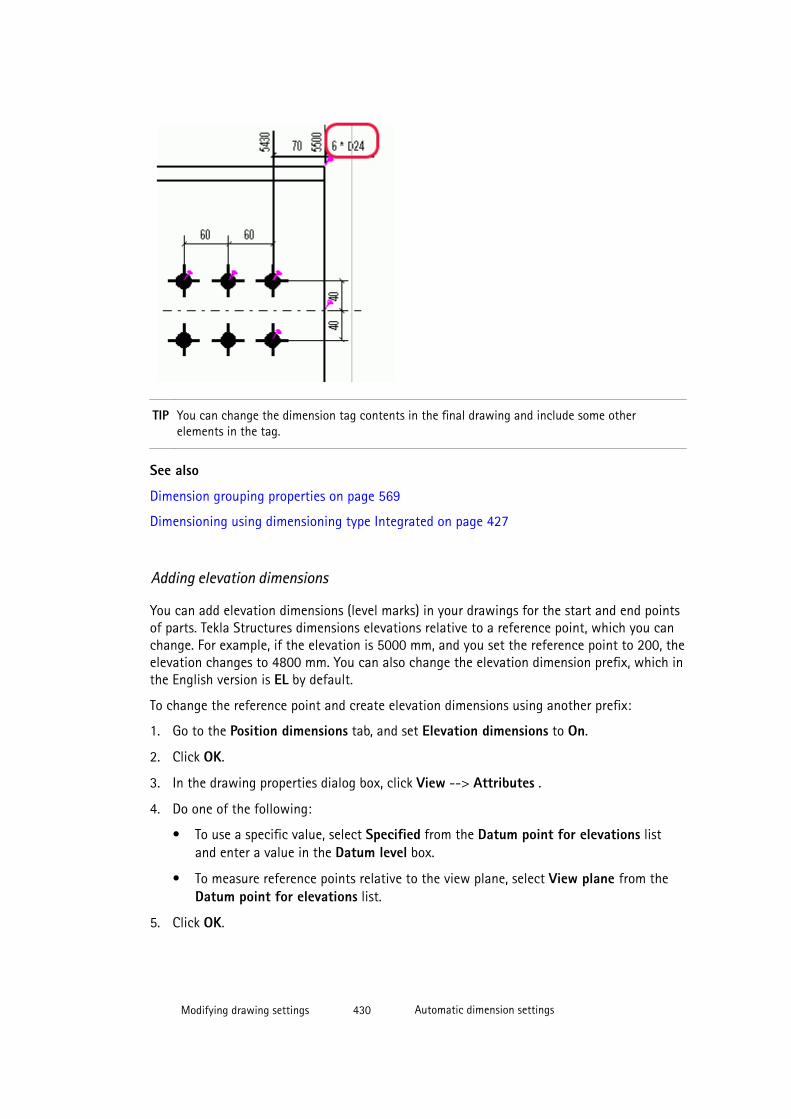
TIP You can change the dimension tag contents in the final drawing and include some otherelements in the tag.
See also
Dimension grouping properties on page 569
Dimensioning using dimensioning type Integrated on page 427
Adding elevation dimensions
You can add elevation dimensions (level marks) in your drawings for the start and end pointsof parts. Tekla Structures dimensions elevations relative to a reference point, which you canchange. For example, if the elevation is 5000 mm, and you set the reference point to 200, theelevation changes to 4800 mm. You can also change the elevation dimension prefix, which inthe English version is EL by default.
To change the reference point and create elevation dimensions using another prefix:
1. Go to the Position dimensions tab, and set Elevation dimensions to On.
2. Click OK.
3. In the drawing properties dialog box, click View --> Attributes .
4. Do one of the following:
• To use a specific value, select Specified from the Datum point for elevations listand enter a value in the Datum level box.
• To measure reference points relative to the view plane, select View plane from theDatum point for elevations list.
5. Click OK.
Modifying drawing settings 430 Automatic dimension settings
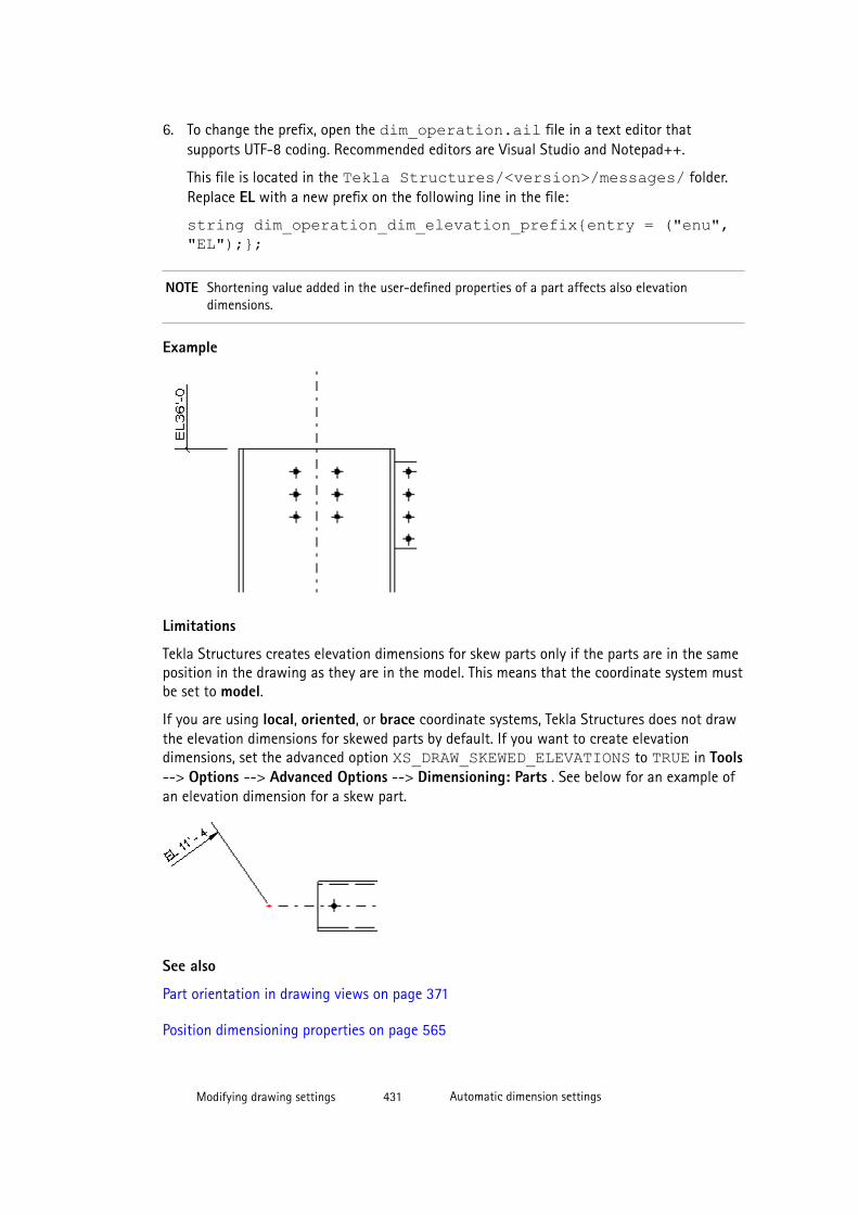
6. To change the prefix, open the dim_operation.ail file in a text editor thatsupports UTF-8 coding. Recommended editors are Visual Studio and Notepad++.
This file is located in the Tekla Structures/<version>/messages/ folder.Replace EL with a new prefix on the following line in the file:
string dim_operation_dim_elevation_prefix{entry = ("enu","EL");};
NOTE Shortening value added in the user-defined properties of a part affects also elevationdimensions.
Example
Limitations
Tekla Structures creates elevation dimensions for skew parts only if the parts are in the sameposition in the drawing as they are in the model. This means that the coordinate system mustbe set to model.
If you are using local, oriented, or brace coordinate systems, Tekla Structures does not drawthe elevation dimensions for skewed parts by default. If you want to create elevationdimensions, set the advanced option XS_DRAW_SKEWED_ELEVATIONS to TRUE in Tools--> Options --> Advanced Options --> Dimensioning: Parts . See below for an example ofan elevation dimension for a skew part.
See also
Part orientation in drawing views on page 371
Position dimensioning properties on page 565
Modifying drawing settings 431 Automatic dimension settings
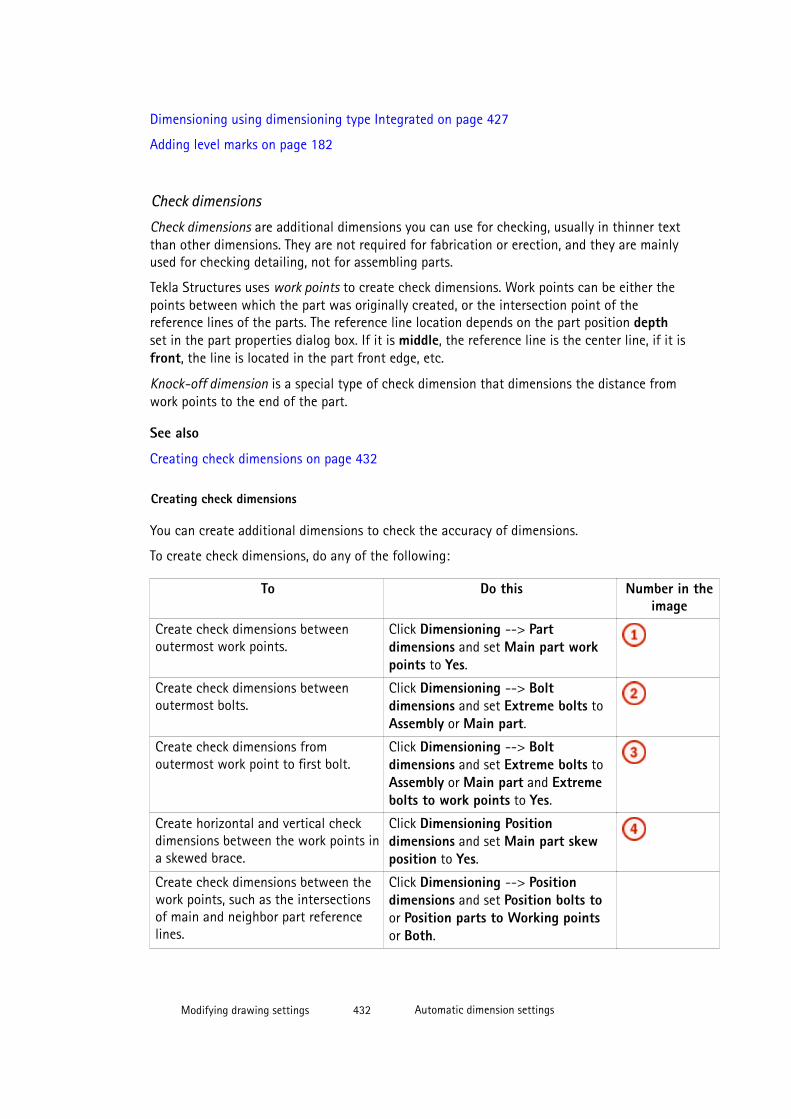
Dimensioning using dimensioning type Integrated on page 427
Adding level marks on page 182
Check dimensions
Check dimensions are additional dimensions you can use for checking, usually in thinner textthan other dimensions. They are not required for fabrication or erection, and they are mainlyused for checking detailing, not for assembling parts.
Tekla Structures uses work points to create check dimensions. Work points can be either thepoints between which the part was originally created, or the intersection point of thereference lines of the parts. The reference line location depends on the part position depthset in the part properties dialog box. If it is middle, the reference line is the center line, if it isfront, the line is located in the part front edge, etc.
Knock-off dimension is a special type of check dimension that dimensions the distance fromwork points to the end of the part.
See also
Creating check dimensions on page 432
Creating check dimensions
You can create additional dimensions to check the accuracy of dimensions.
To create check dimensions, do any of the following:
To Do this Number in theimage
Create check dimensions betweenoutermost work points.
Click Dimensioning --> Partdimensions and set Main part workpoints to Yes.
Create check dimensions betweenoutermost bolts.
Click Dimensioning --> Boltdimensions and set Extreme bolts toAssembly or Main part.
Create check dimensions fromoutermost work point to first bolt.
Click Dimensioning --> Boltdimensions and set Extreme bolts toAssembly or Main part and Extremebolts to work points to Yes.
Create horizontal and vertical checkdimensions between the work points ina skewed brace.
Click Dimensioning Positiondimensions and set Main part skewposition to Yes.
Create check dimensions between thework points, such as the intersectionsof main and neighbor part referencelines.
Click Dimensioning --> Positiondimensions and set Position bolts toor Position parts to Working pointsor Both.
Modifying drawing settings 432 Automatic dimension settings

To Do this Number in theimage
Create check dimensions to the bolthole locations in the main part.
Click Dimensioning --> Positiondimensions and set Main part boltposition to On.
Create knock-off dimensions. Click Dimensioning --> Partdimensions and set Knock-offdimensions to On.
TIP To change the appearance of the check dimensions and the type of the knock-offdimension to use, click Dimension in the drawing properties dialog box and go to theAdvanced tab.
Modifying drawing settings 433 Automatic dimension settings
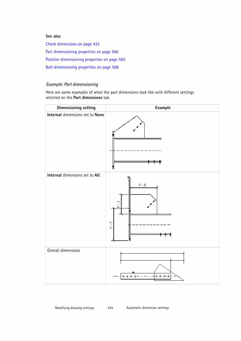
See also
Check dimensions on page 432
Part dimensioning properties on page 566
Position dimensioning properties on page 565
Bolt dimensioning properties on page 568
Example: Part dimensioning
Here are some examples of what the part dimensions look like with different settingsselected on the Part dimensions tab.
Dimensioning setting Example
Internal dimensions set to None
Internal dimensions set to All.
Overall dimensions
Modifying drawing settings 434 Automatic dimension settings
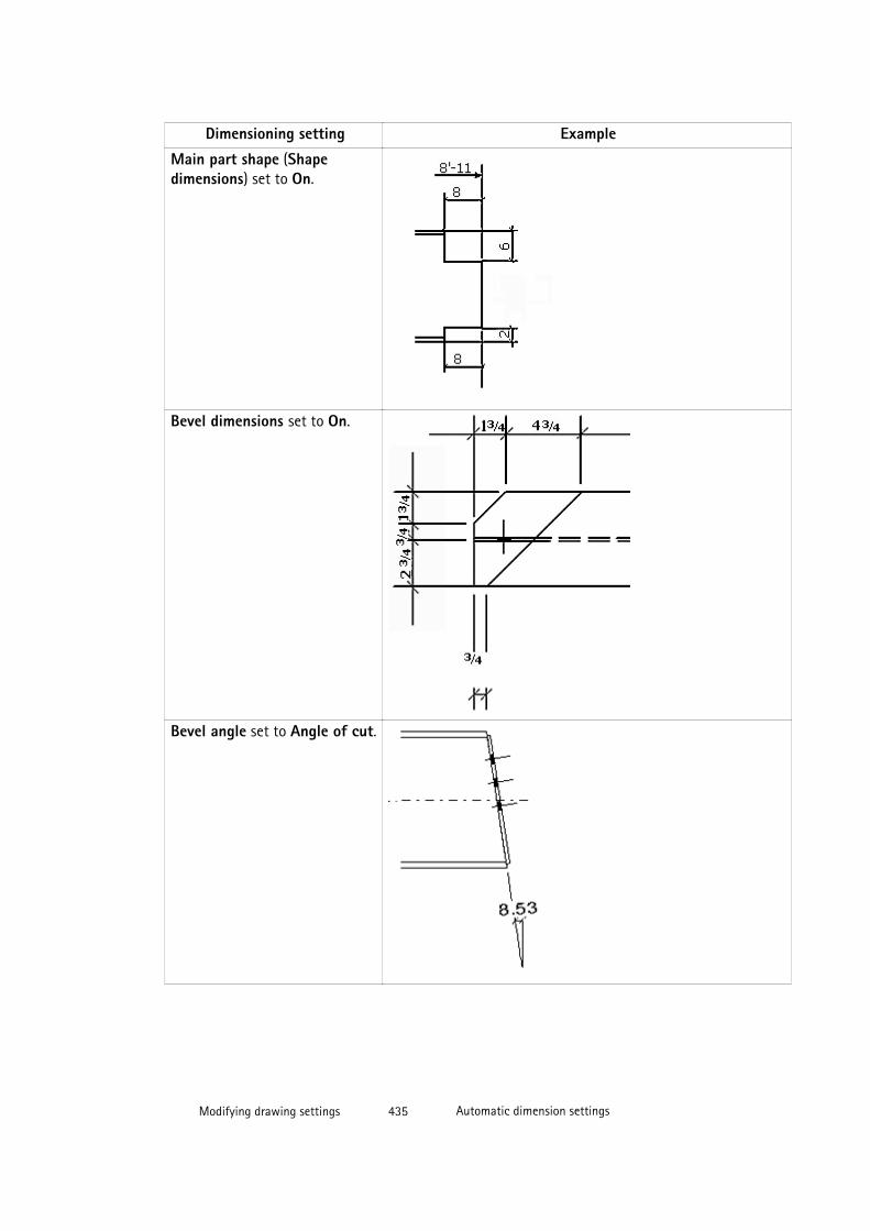
Dimensioning setting Example
Main part shape (Shapedimensions) set to On.
Bevel dimensions set to On.
Bevel angle set to Angle of cut.
Modifying drawing settings 435 Automatic dimension settings
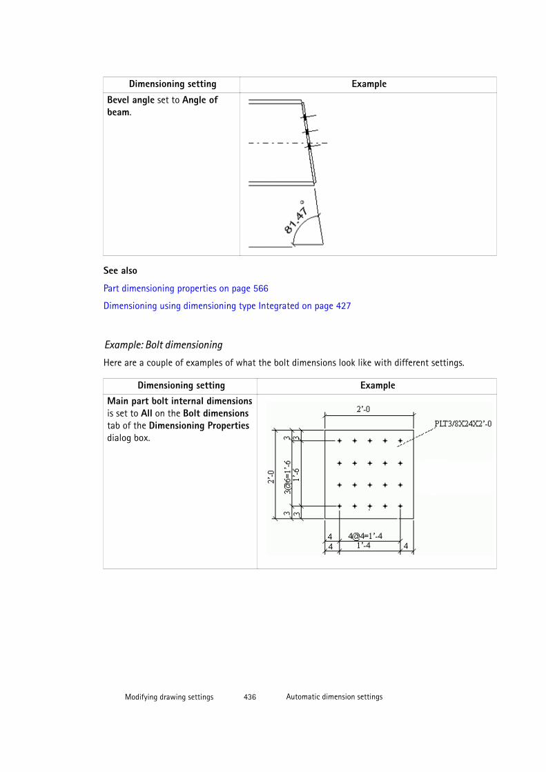
Dimensioning setting Example
Bevel angle set to Angle ofbeam.
See also
Part dimensioning properties on page 566
Dimensioning using dimensioning type Integrated on page 427
Example: Bolt dimensioning
Here are a couple of examples of what the bolt dimensions look like with different settings.
Dimensioning setting ExampleMain part bolt internal dimensionsis set to All on the Bolt dimensionstab of the Dimensioning Propertiesdialog box.
Modifying drawing settings 436 Automatic dimension settings

Dimensioning setting Example
All bolt and hole dimensions areshown in the front view of the mainassembly. The elements Gage ofoutstanding leg (GOL) and Center-to-center distance (C/C or Gage)have been added in a bolt and holemark in Bolt mark... > Content.
See also
Bolt dimensioning properties on page 568
Bolt mark elements on page 586
Dimensioning using dimensioning type Integrated on page 427
Example: Position dimensioning
Here are some examples of what the position dimensions look like with different settingsselected on the Position dimensions tab.
Dimensioning setting Example
Position parts to is set to None.
Modifying drawing settings 437 Automatic dimension settings
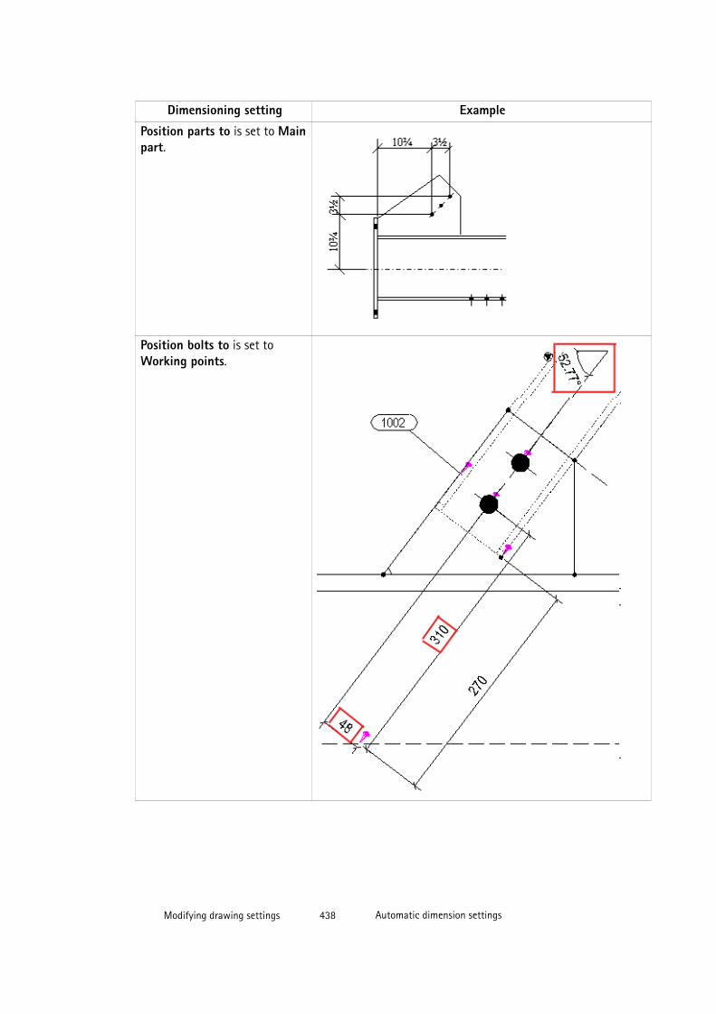
Dimensioning setting Example
Position parts to is set to Mainpart.
Position bolts to is set toWorking points.
Modifying drawing settings 438 Automatic dimension settings
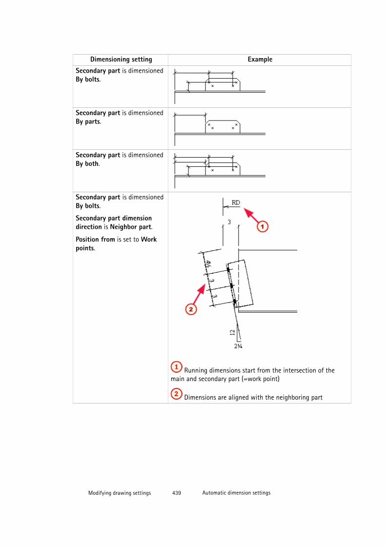
Dimensioning setting Example
Secondary part is dimensionedBy bolts.
Secondary part is dimensionedBy parts.
Secondary part is dimensionedBy both.
Secondary part is dimensionedBy bolts.
Secondary part dimensiondirection is Neighbor part.
Position from is set to Workpoints.
Running dimensions start from the intersection of themain and secondary part (=work point)
Dimensions are aligned with the neighboring part
Modifying drawing settings 439 Automatic dimension settings
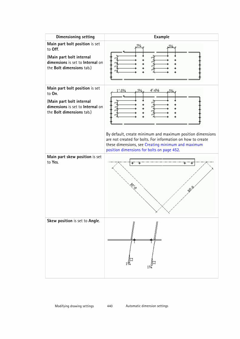
Dimensioning setting Example
Main part bolt position is setto Off.
(Main part bolt internaldimensions is set to Internal onthe Bolt dimensions tab.)
Main part bolt position is setto On.
(Main part bolt internaldimensions is set to Internal onthe Bolt dimensions tab.)
By default, create minimum and maximum position dimensionsare not created for bolts. For information on how to createthese dimensions, see Creating minimum and maximumposition dimensions for bolts on page 452.
Main part skew position is setto Yes.
Skew position is set to Angle.
Modifying drawing settings 440 Automatic dimension settings
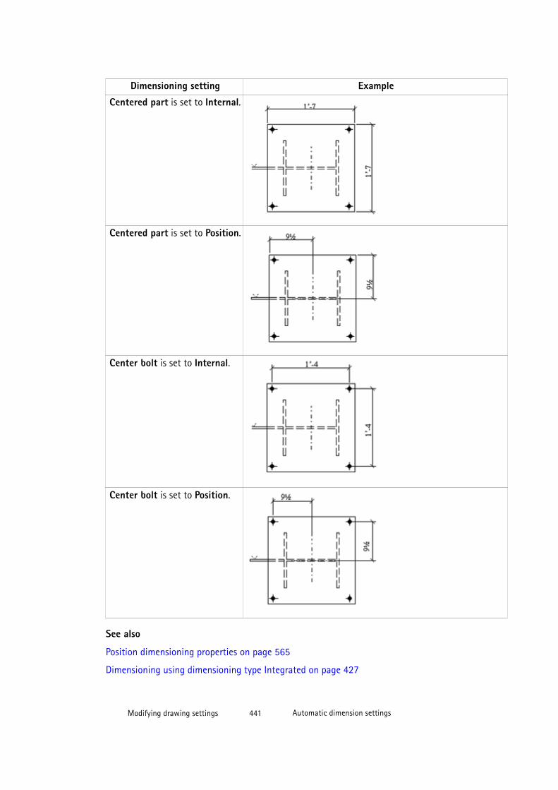
Dimensioning setting Example
Centered part is set to Internal.
Centered part is set to Position.
Center bolt is set to Internal.
Center bolt is set to Position.
See also
Position dimensioning properties on page 565
Dimensioning using dimensioning type Integrated on page 427
Modifying drawing settings 441 Automatic dimension settings
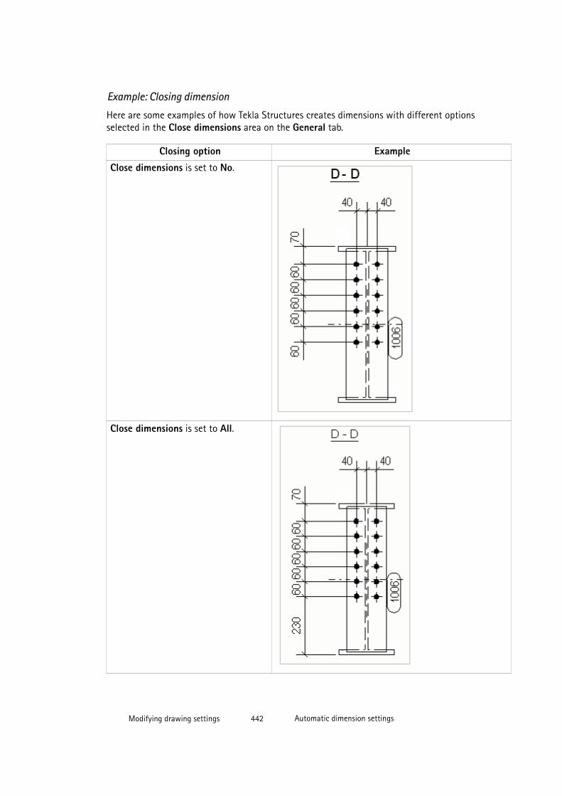
Example: Closing dimension
Here are some examples of how Tekla Structures creates dimensions with different optionsselected in the Close dimensions area on the General tab.
Closing option Example
Close dimensions is set to No.
Close dimensions is set to All.
Modifying drawing settings 442 Automatic dimension settings

Closing option Example
Short dimensions is set to No.
See also
General dimensioning properties on page 562
Dimensioning using dimensioning type Integrated on page 427
Example: Combining dimensions
Here are some examples of how Tekla Structures combines dimensions with different optionsselected on the General tab.
Combining option Example
Option No prevents dimensions frombeing combined.
Option 1 combines part positiondimensions with part internaldimensions, and bolt group internaldimensions with bolt edge distances.Bolt position dimensions are notcombined with bolt internaldimensions.
Modifying drawing settings 443 Automatic dimension settings
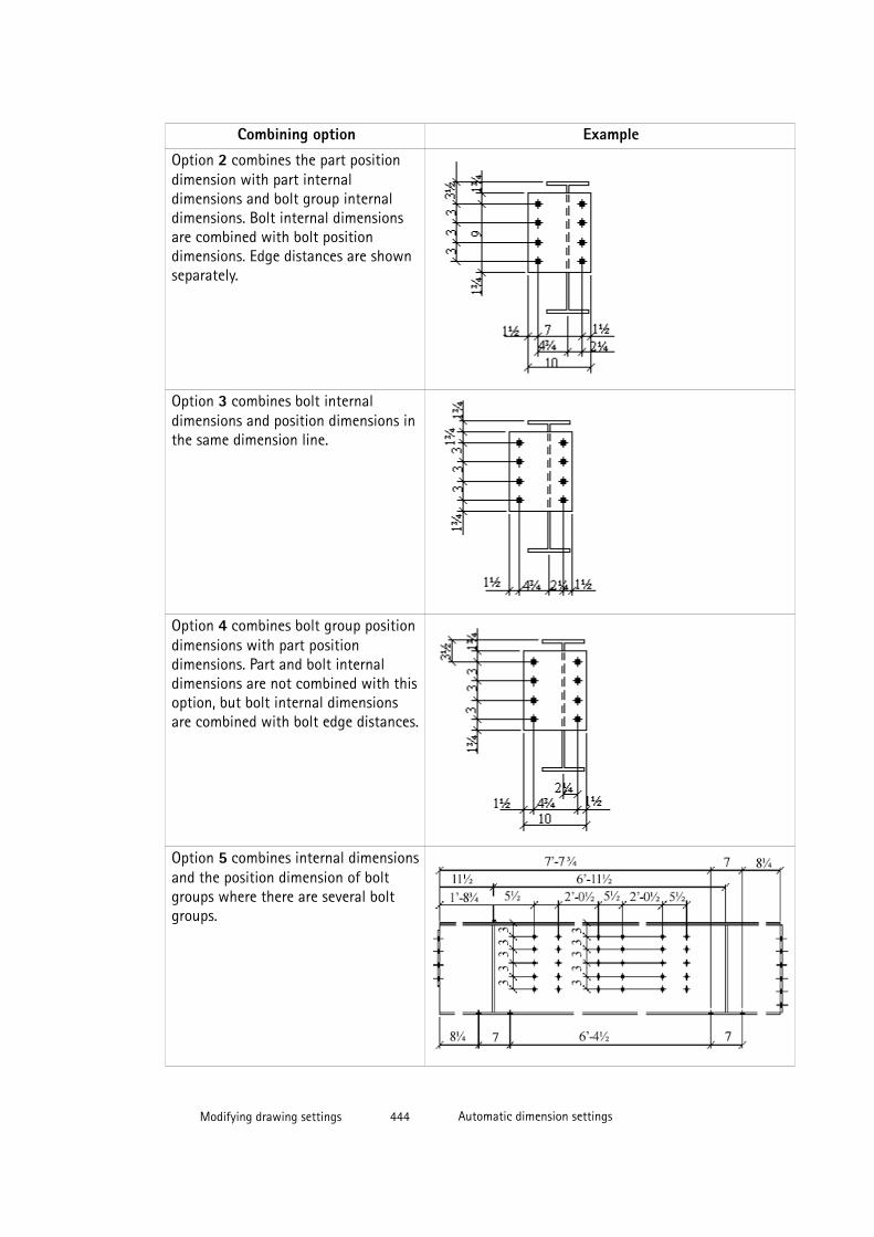
Combining option Example
Option 2 combines the part positiondimension with part internaldimensions and bolt group internaldimensions. Bolt internal dimensionsare combined with bolt positiondimensions. Edge distances are shownseparately.
Option 3 combines bolt internaldimensions and position dimensions inthe same dimension line.
Option 4 combines bolt group positiondimensions with part positiondimensions. Part and bolt internaldimensions are not combined with thisoption, but bolt internal dimensionsare combined with bolt edge distances.
Option 5 combines internal dimensionsand the position dimension of boltgroups where there are several boltgroups.
Modifying drawing settings 444 Automatic dimension settings
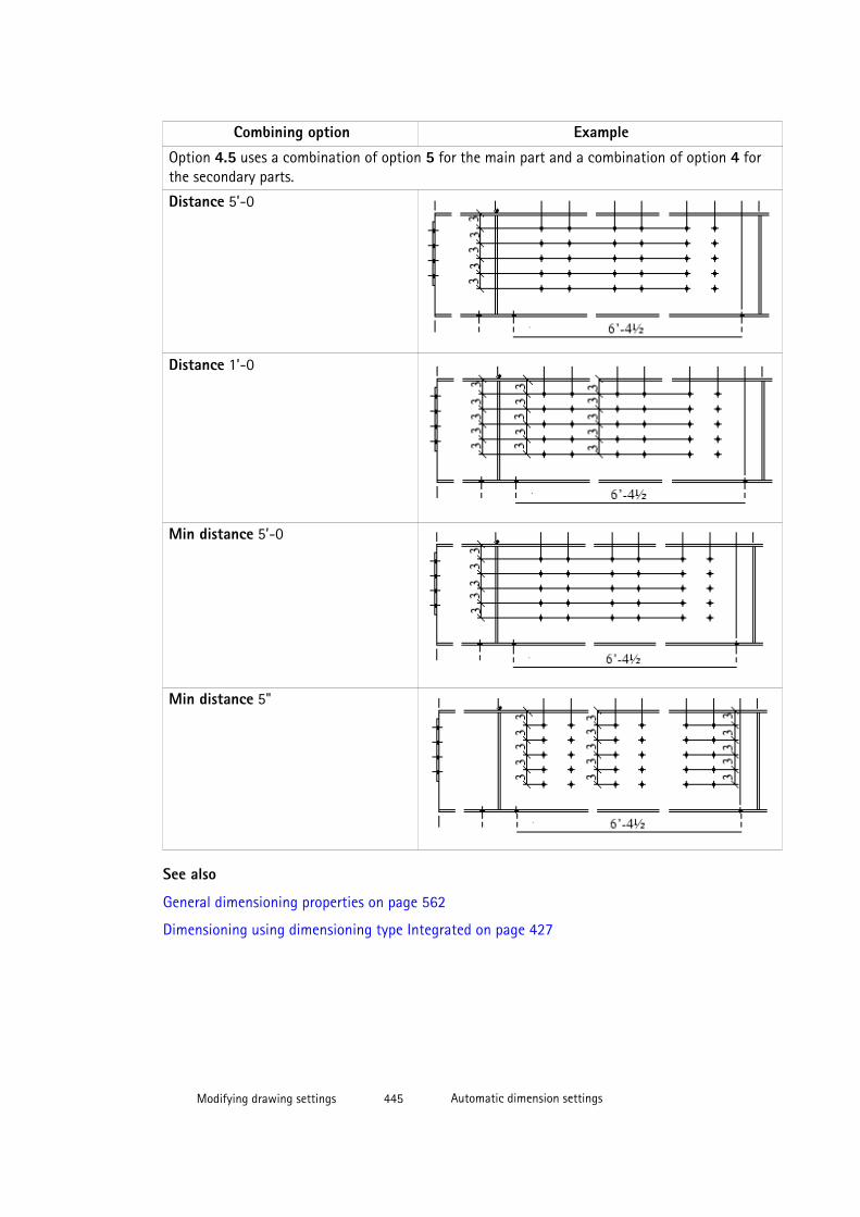
Combining option Example
Option 4.5 uses a combination of option 5 for the main part and a combination of option 4 forthe secondary parts.
Distance 5’-0
Distance 1’-0
Min distance 5’-0
Min distance 5"
See also
General dimensioning properties on page 562
Dimensioning using dimensioning type Integrated on page 427
Modifying drawing settings 445 Automatic dimension settings
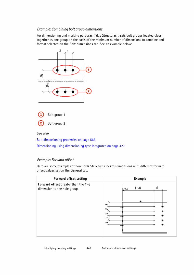
Example: Combining bolt group dimensions
For dimensioning and marking purposes, Tekla Structures treats bolt groups located closetogether as one group on the basis of the minimum number of dimensions to combine andformat selected on the Bolt dimensions tab. See an example below:
Bolt group 1
Bolt group 2
See also
Bolt dimensioning properties on page 568
Dimensioning using dimensioning type Integrated on page 427
Example: Forward offset
Here are some examples of how Tekla Structures locates dimensions with different forwardoffset values set on the General tab.
Forward offset setting Example
Forward offset greater than the 1’-8dimension to the hole group.
Modifying drawing settings 446 Automatic dimension settings
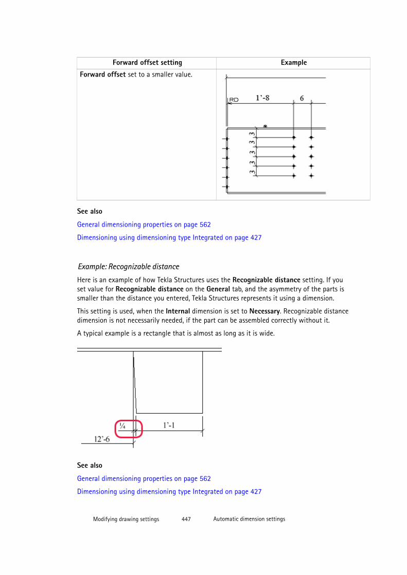
Forward offset setting Example
Forward offset set to a smaller value.
See also
General dimensioning properties on page 562
Dimensioning using dimensioning type Integrated on page 427
Example: Recognizable distance
Here is an example of how Tekla Structures uses the Recognizable distance setting. If youset value for Recognizable distance on the General tab, and the asymmetry of the parts issmaller than the distance you entered, Tekla Structures represents it using a dimension.
This setting is used, when the Internal dimension is set to Necessary. Recognizable distancedimension is not necessarily needed, if the part can be assembled correctly without it.
A typical example is a rectangle that is almost as long as it is wide.
See also
General dimensioning properties on page 562
Dimensioning using dimensioning type Integrated on page 427
Modifying drawing settings 447 Automatic dimension settings

Example: Preferred dimension side
You can set the preferred dimension side for parts and bolts on the Part dimensions tab andBolt dimensions tab.The examples below show how the different settings for Preferred dimside look like for part dimensions.
See also
Part dimensioning properties on page 566
Bolt dimensioning properties on page 568
Dimensioning using dimensioning type Integrated on page 427
Modifying drawing settings 448 Automatic dimension settings

Example: Reinforcement dimension
Here are some examples of how Tekla Structures creates dimensions for reinforcing bargroups with different options selected on the Reinforcement dimensions tab.
Settings ExampleDimensions for reinforcing bargroups is set to On, no dimensiontags selected in Mark location.
Dimensions for reinforcing bargroups is set to On, dimension tagsselected in Mark location.
Dimensions for reinforcing bargroups is set to On, dimension tagsselected in Mark location, Closedimensions to binding geometry isset to Yes.
See also
Reinforcement dimensioning properties on page 570
Dimensioning using dimensioning type Integrated on page 427
Adding automatic dual dimensions
You can create dual dimension tags automatically in all types of drawings.
Limitations:
Dual dimensions can only be shown in relative and US absolute dimensions, but not inabsolute dimensions.
To create dual dimensions:
1. Click Click Tools --> Options --> Options and select Drawing dimensions.
2. Set the units, format and precision.
3. Select the drawing types where you want to have the dual dimensions.
4. Click OK.
Modifying drawing settings 449 Automatic dimension settings
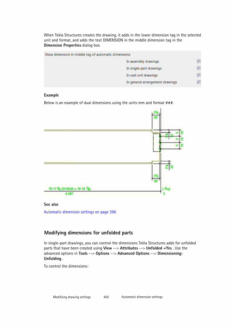
When Tekla Structures creates the drawing, it adds in the lower dimension tag in the selectedunit and format, and adds the text DIMENSION in the middle dimension tag in theDimension Properties dialog box.
Example
Below is an example of dual dimensions using the units mm and format ###.
See also
Automatic dimension settings on page 396
Modifying dimensions for unfolded parts
In single-part drawings, you can control the dimensions Tekla Structures adds for unfoldedparts that have been created using View --> Attributes --> Unfolded =Yes . Use theadvanced options in Tools --> Options --> Advanced Options --> Dimensioning:Unfolding .
To control the dimensions:
Modifying drawing settings 450 Automatic dimension settings
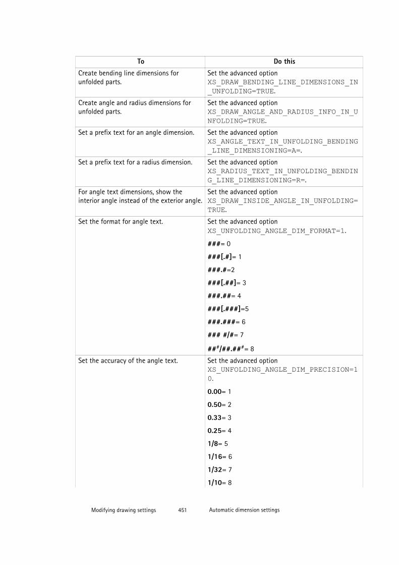
To Do this
Create bending line dimensions forunfolded parts.
Set the advanced option XS_DRAW_BENDING_LINE_DIMENSIONS_IN_UNFOLDING=TRUE.
Create angle and radius dimensions forunfolded parts.
Set the advanced option XS_DRAW_ANGLE_AND_RADIUS_INFO_IN_UNFOLDING=TRUE.
Set a prefix text for an angle dimension. Set the advanced option XS_ANGLE_TEXT_IN_UNFOLDING_BENDING_LINE_DIMENSIONING=A=.
Set a prefix text for a radius dimension. Set the advanced option XS_RADIUS_TEXT_IN_UNFOLDING_BENDING_LINE_DIMENSIONING=R=.
For angle text dimensions, show theinterior angle instead of the exterior angle.
Set the advanced option XS_DRAW_INSIDE_ANGLE_IN_UNFOLDING=TRUE.
Set the format for angle text. Set the advanced option XS_UNFOLDING_ANGLE_DIM_FORMAT=1.
###= 0
###[.#]= 1
###.#=2
###[.##]= 3
###.##= 4
###[.###]=5
###.###= 6
### #/#= 7
###/##.###= 8
Set the accuracy of the angle text. Set the advanced option XS_UNFOLDING_ANGLE_DIM_PRECISION=10.
0.00= 1
0.50= 2
0.33= 3
0.25= 4
1/8= 5
1/16= 6
1/32= 7
1/10= 8
Modifying drawing settings 451 Automatic dimension settings

To Do this1/100= 9
1/1000= 10
See also
Dimension format, precision and unit properties on page 558
Dimensioning using dimensioning type Integrated on page 427
Creating minimum and maximum position dimensions for bolts
By default, Tekla Structures does not create minimum and maximum position dimensions forbolts.
To create minimum and maximum position dimensions for bolts:
1. Go to Tools --> Options --> Advanced Options --> Dimensioning: Bolts
2. Set XS_BOLT_POSITION_TO_MIN_AND_MAX_POINT to TRUE .
The examples below show a maximum bolt dimension of 40:
Setting Example
Before setting the advanced option.
After setting the advanced option to TRUE.
Dimensioning using dimensioning type Integrated on page 427
Modifying drawing settings 452 Automatic dimension settings
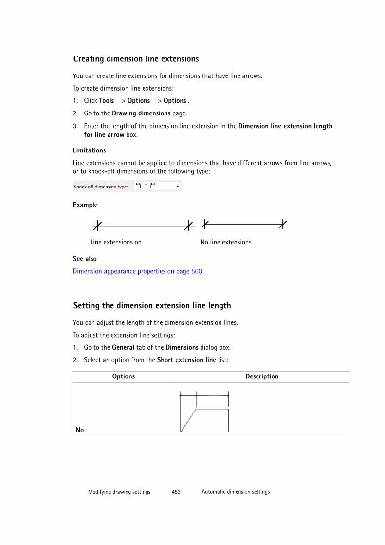
Creating dimension line extensions
You can create line extensions for dimensions that have line arrows.
To create dimension line extensions:
1. Click Tools --> Options --> Options .
2. Go to the Drawing dimensions page.
3. Enter the length of the dimension line extension in the Dimension line extension lengthfor line arrow box.
Limitations
Line extensions cannot be applied to dimensions that have different arrows from line arrows,or to knock-off dimensions of the following type:
Example
Line extensions on No line extensions
See also
Dimension appearance properties on page 560
Setting the dimension extension line length
You can adjust the length of the dimension extension lines.
To adjust the extension line settings:
1. Go to the General tab of the Dimensions dialog box.
2. Select an option from the Short extension line list:
Options Description
No
Modifying drawing settings 453 Automatic dimension settings
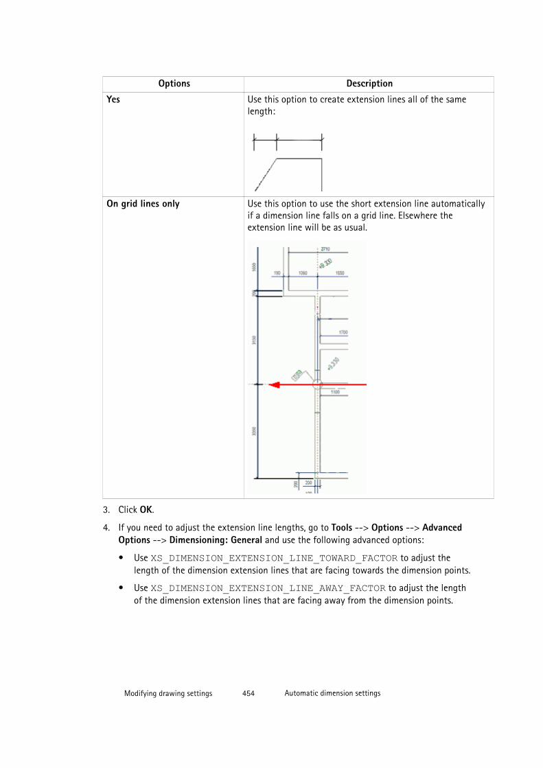
Options Description
Yes Use this option to create extension lines all of the samelength:
On grid lines only Use this option to use the short extension line automaticallyif a dimension line falls on a grid line. Elsewhere theextension line will be as usual.
3. Click OK.
4. If you need to adjust the extension line lengths, go to Tools --> Options --> AdvancedOptions --> Dimensioning: General and use the following advanced options:
• Use XS_DIMENSION_EXTENSION_LINE_TOWARD_FACTOR to adjust thelength of the dimension extension lines that are facing towards the dimension points.
• Use XS_DIMENSION_EXTENSION_LINE_AWAY_FACTOR to adjust the lengthof the dimension extension lines that are facing away from the dimension points.
Modifying drawing settings 454 Automatic dimension settings
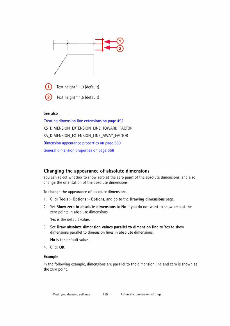
Text height * 1.0 (default)
Text height * 1.5 (default)
See also
Creating dimension line extensions on page 452
XS_DIMENSION_EXTENSION_LINE_TOWARD_FACTOR
XS_DIMENSION_EXTENSION_LINE_AWAY_FACTOR
Dimension appearance properties on page 560
General dimension properties on page 556
Changing the appearance of absolute dimensionsYou can select whether to show zero at the zero point of the absolute dimensions, and alsochange the orientation of the absolute dimensions.
To change the appearance of absolute dimensions:
1. Click Tools > Options > Options, and go to the Drawing dimensions page.
2. Set Show zero in absolute dimensions to No if you do not want to show zero at thezero points in absolute dimensions.
Yes is the default value.
3. Set Draw absolute dimension values parallel to dimension line to Yes to showdimensions parallel to dimension lines in absolute dimensions.
No is the default value.
4. Click OK.
Example
In the following example, dimensions are parallel to the dimension line and zero is shown atthe zero point.
Modifying drawing settings 455 Automatic dimension settings
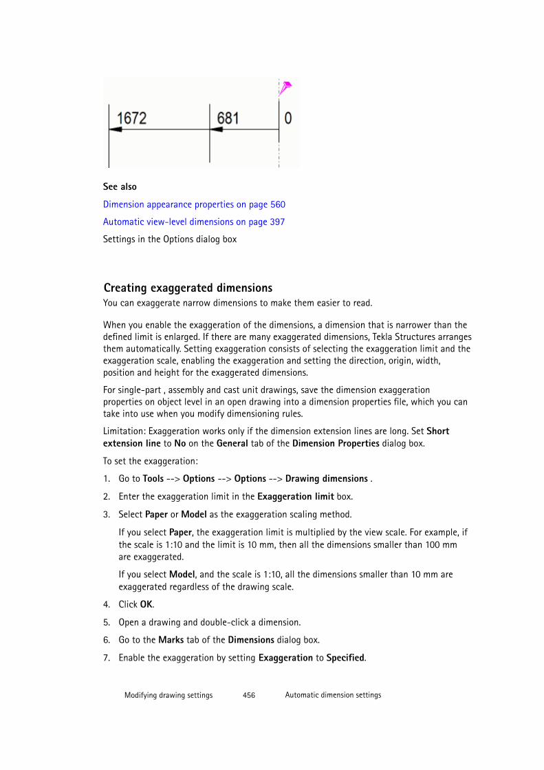
See also
Dimension appearance properties on page 560
Automatic view-level dimensions on page 397
Settings in the Options dialog box
Creating exaggerated dimensionsYou can exaggerate narrow dimensions to make them easier to read.
When you enable the exaggeration of the dimensions, a dimension that is narrower than thedefined limit is enlarged. If there are many exaggerated dimensions, Tekla Structures arrangesthem automatically. Setting exaggeration consists of selecting the exaggeration limit and theexaggeration scale, enabling the exaggeration and setting the direction, origin, width,position and height for the exaggerated dimensions.
For single-part , assembly and cast unit drawings, save the dimension exaggerationproperties on object level in an open drawing into a dimension properties file, which you cantake into use when you modify dimensioning rules.
Limitation: Exaggeration works only if the dimension extension lines are long. Set Shortextension line to No on the General tab of the Dimension Properties dialog box.
To set the exaggeration:
1. Go to Tools --> Options --> Options --> Drawing dimensions .
2. Enter the exaggeration limit in the Exaggeration limit box.
3. Select Paper or Model as the exaggeration scaling method.
If you select Paper, the exaggeration limit is multiplied by the view scale. For example, ifthe scale is 1:10 and the limit is 10 mm, then all the dimensions smaller than 100 mmare exaggerated.
If you select Model, and the scale is 1:10, all the dimensions smaller than 10 mm areexaggerated regardless of the drawing scale.
4. Click OK.
5. Open a drawing and double-click a dimension.
6. Go to the Marks tab of the Dimensions dialog box.
7. Enable the exaggeration by setting Exaggeration to Specified.
Modifying drawing settings 456 Automatic dimension settings
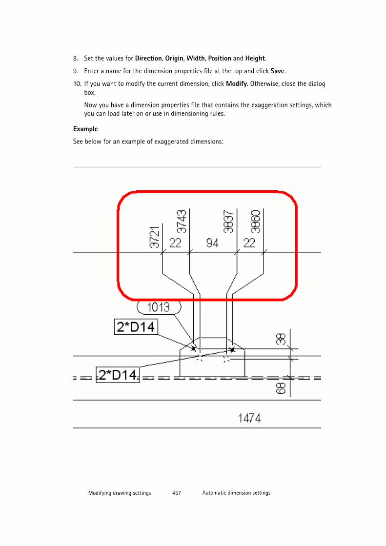
8. Set the values for Direction, Origin, Width, Position and Height.
9. Enter a name for the dimension properties file at the top and click Save.
10. If you want to modify the current dimension, click Modify. Otherwise, close the dialogbox.
Now you have a dimension properties file that contains the exaggeration settings, whichyou can load later on or use in dimensioning rules.
Example
See below for an example of exaggerated dimensions:
Modifying drawing settings 457 Automatic dimension settings
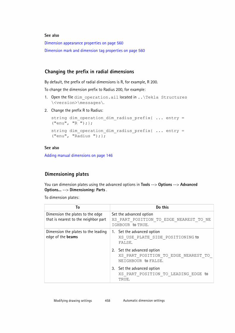
See also
Dimension appearance properties on page 560
Dimension mark and dimension tag properties on page 560
Changing the prefix in radial dimensions
By default, the prefix of radial dimensions is R, for example, R 200.
To change the dimension prefix to Radius 200, for example:
1. Open the file dim_operation.ail located in ..\Tekla Structures\<version>\messages\.
2. Change the prefix R to Radius:
string dim_operation_dim_radius_prefix{ ... entry =("enu", "R ");};string dim_operation_dim_radius_prefix{ ... entry =("enu", "Radius ");};
See also
Adding manual dimensions on page 146
Dimensioning plates
You can dimension plates using the advanced options in Tools --> Options --> AdvancedOptions... --> Dimensioning: Parts .
To dimension plates:
To Do this
Dimension the plates to the edgethat is nearest to the neighbor part
Set the advanced option XS_PART_POSITION_TO_EDGE_NEAREST_TO_NEIGHBOUR to TRUE.
Dimension the plates to the leadingedge of the beams
1. Set the advanced option XS_USE_PLATE_SIDE_POSITIONING to FALSE.
2. Set the advanced option XS_PART_POSITION_TO_EDGE_NEAREST_TO_NEIGHBOUR to FALSE.
3. Set the advanced optionXS_PART_POSITION_TO_LEADING_EDGE to TRUE.
Modifying drawing settings 458 Automatic dimension settings
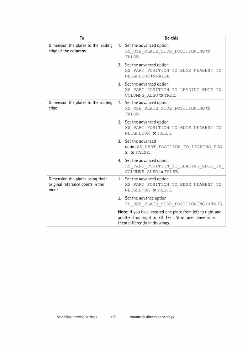
To Do this
Dimension the plates to the leadingedge of the columns
1. Set the advanced option XS_USE_PLATE_SIDE_POSITIONING to FALSE.
2. Set the advanced option XS_PART_POSITION_TO_EDGE_NEAREST_TO_NEIGHBOUR to FALSE.
3. Set the advanced option XS_PART_POSITION_TO_LEADING_EDGE_IN_COLUMNS_ALSO to TRUE.
Dimension the plates to the trailingedge
1. Set the advanced option XS_USE_PLATE_SIDE_POSITIONING to FALSE.
2. Set the advanced option XS_PART_POSITION_TO_EDGE_NEAREST_TO_NEIGHBOUR to FALSE.
3. Set the advancedoptionXS_PART_POSITION_TO_LEADING_EDGE to FALSE.
4. Set the advanced option XS_PART_POSITION_TO_LEADING_EDGE_IN_COLUMNS_ALSO to FALSE.
Dimension the plates using theiroriginal reference points in themodel
1. Set the advanced option XS_PART_POSITION_TO_EDGE_NEAREST_TO_NEIGHBOUR to FALSE.
2. Set the advance option XS_USE_PLATE_SIDE_POSITIONING to TRUE.
Note: If you have created one plate from left to right andanother from right to left, Tekla Structures dimensionsthem differently in drawings.
Modifying drawing settings 459 Automatic dimension settings
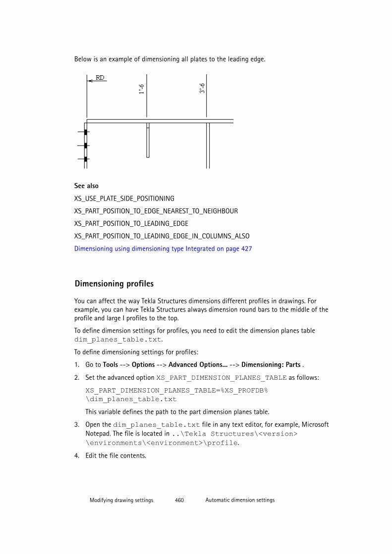
Below is an example of dimensioning all plates to the leading edge.
See also
XS_USE_PLATE_SIDE_POSITIONING
XS_PART_POSITION_TO_EDGE_NEAREST_TO_NEIGHBOUR
XS_PART_POSITION_TO_LEADING_EDGE
XS_PART_POSITION_TO_LEADING_EDGE_IN_COLUMNS_ALSO
Dimensioning using dimensioning type Integrated on page 427
Dimensioning profiles
You can affect the way Tekla Structures dimensions different profiles in drawings. Forexample, you can have Tekla Structures always dimension round bars to the middle of theprofile and large I profiles to the top.
To define dimension settings for profiles, you need to edit the dimension planes tabledim_planes_table.txt.
To define dimensioning settings for profiles:
1. Go to Tools --> Options --> Advanced Options... --> Dimensioning: Parts .
2. Set the advanced option XS_PART_DIMENSION_PLANES_TABLE as follows:
XS_PART_DIMENSION_PLANES_TABLE=%XS_PROFDB%\dim_planes_table.txtThis variable defines the path to the part dimension planes table.
3. Open the dim_planes_table.txt file in any text editor, for example, MicrosoftNotepad. The file is located in ..\Tekla Structures\<version>\environments\<environment>\profile.
4. Edit the file contents.
Modifying drawing settings 460 Automatic dimension settings
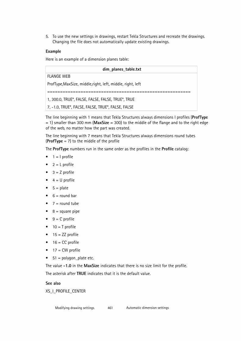
5. To use the new settings in drawings, restart Tekla Structures and recreate the drawings.Changing the file does not automatically update existing drawings.
Example
Here is an example of a dimension planes table:
dim_planes_table.txt
FLANGE WEB
ProfType,MaxSize, middle,right, left, middle, right, left
========================================================
1, 300.0, TRUE*, FALSE, FALSE, FALSE, TRUE*, TRUE
7, -1.0, TRUE*, FALSE, FALSE, TRUE*, FALSE, FALSE
The line beginning with 1 means that Tekla Structures always dimensions I profiles (ProfType= 1) smaller than 300 mm (MaxSize = 300) to the middle of the flange and to the right edgeof the web, no matter how the part was created.
The line beginning with 7 means that Tekla Structures always dimensions round tubes(ProfType = 7) to the middle of the profile
The ProfType numbers run in the same order as the profiles in the Profile catalog:
• 1 = I profile
• 2 = L profile
• 3 = Z profile
• 4 = U profile
• 5 = plate
• 6 = round bar
• 7 = round tube
• 8 = square pipe
• 9 = C profile
• 10 = T profile
• 15 = ZZ profile
• 16 = CC profile
• 17 = CW profile
• 51 = polygon_plate etc.
The value -1.0 in the MaxSize indicates that there is no size limit for the profile.
The asterisk after TRUE indicates that it is the default value.
See also
XS_I_PROFILE_CENTER
Modifying drawing settings 461 Automatic dimension settings

XS_DO_NOT_CREATE_PROFILE_DIMENSIONS_FOR_CONCRETE
XS_PART_DIMENSION_PLANES_TABLE
Dimensioning using dimensioning type Integrated on page 427
Sloped dimension textsTekla Structures aligns slightly sloped dimension text. If the dimension text is sloped morethan a certain degree, Tekla Structures flips the text.
Below is an example of a dimension text that is slightly sloped.
Below is an example of a flipped dimension text.
The default limit for aligning dimension text is 0.1 (5.74 degrees). When this limit isexceeded, the dimension text gets flipped. To adjust this limit, use the advanced option XS_TEXT_ORIENTATION_EPSILON.
See also
XS_TEXT_ORIENTATION_EPSILON
Modifying drawing settings 462 Automatic dimension settings
Automatic dimensioning of general arrangement drawings
In the general arrangement drawing General - Dimensioning Properties dialog box, you cancreate part, grid and overall dimensions, and control the way they are created. You canexperiment with different combinations of options to achieve different kinds of dimensioningeffects.
To select the dimensions to create and modify the dimensioning settings:
1. Click Drawings & Reports --> Drawing Settings --> General Arrangement Drawings .
2. Click Dimensioning.
3. Select the dimensions to create and modify the related settings.
4. On the Grids tab, adjust the grid dimension and overall dimension creation settings andthe positioning of the dimensions.
5. On the Parts tab, adjust part dimension creation settings and the positioning of thedimensions.
6. Click OK.
See also
Object groups in dimensioning on page 463
Dimensioning object groups on different dimension lines on page 464
Example: Grid and overall dimensions on page 465
Example: Using maximum leader line length options on page 467
Example: Dimensioning parts partly outside the view on page 468
Example: Limiting the number of outside dimensions on page 469
Example: Part dimension positioning on page 470
Example: Dimensions in anchor bolt plans on page 476
Grid and overall dimensioning properties (GA drawings) on page 571
Part dimensioning properties (GA drawings) on page 572
Object groups in dimensioning
In dimensioning of general arrangement drawings, the term object group refers to objectsthat have been grouped together for the purpose of dimensioning object groups on differentdimension lines.
You can use the object groups (selection filters) that you have created when modeling, orcreate the necessary groups through the Parts tab in the General - Dimensioning Propertiesdialog box. For example, you might want to create an object group for beams of a certainsize.
Modifying drawing settings 463 Automatic dimension settings
See also
Filtering objects
Dimensioning object groups on different dimension lines on page 464
Dimensioning object groups on different dimension lines
You can use object groups to specify different objects to be dimensioned on differentdimension lines.
To do this:
1. Go to the Parts tab of the General - Dimensioning Properties dialog box.
2. Add the desired object groups to dimensioning rules by clicking Add rule and selectingthe rule from the list in the Object group column.
3. If needed, you can create object groups of your own by clicking Object group. Forexample, add object group rules for beams of different size.
4. For each object group, select the Positioning option, the Horizontal position option, andthe Vertical position option, depending on the type of the objects in the group. Forexample, for beam groups, set Horizontal position to Left side to position the beamdimensions to the left side of the grid.
5. If needed, in the Tag column, enter the text tags that you want to display for thedifferent object groups in the drawing. For example, enter the size of the beam.
Example
In this example, we created several beam groups, one for each beam size to be dimensioned,then selected the position for the dimensions in different groups, and added tags to bedisplayed for each group:
Modifying drawing settings 464 Automatic dimension settings
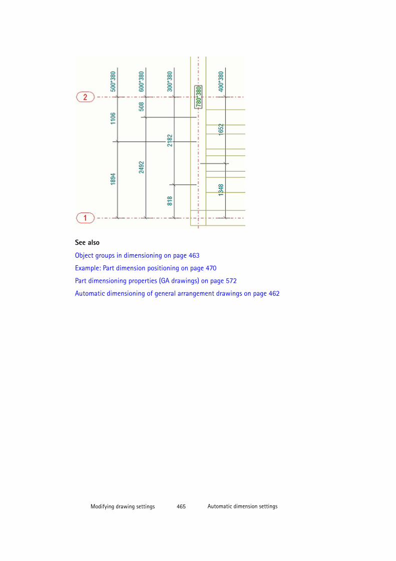
See also
Object groups in dimensioning on page 463
Example: Part dimension positioning on page 470
Part dimensioning properties (GA drawings) on page 572
Automatic dimensioning of general arrangement drawings on page 462
Modifying drawing settings 465 Automatic dimension settings

Example: Grid and overall dimensions
Here are some examples of what the grid and overall dimensions look like with differentsettings selected on the Grid tab.
Dimensioning setting Example
Grid line dimensions is set to On,Overall dimension to On, Horizontalto Left, and Vertical to above.
Grid line dimensions is set to On,Overall dimension to Off, Horizontalto Left, and Vertical to above.
Modifying drawing settings 466 Automatic dimension settings
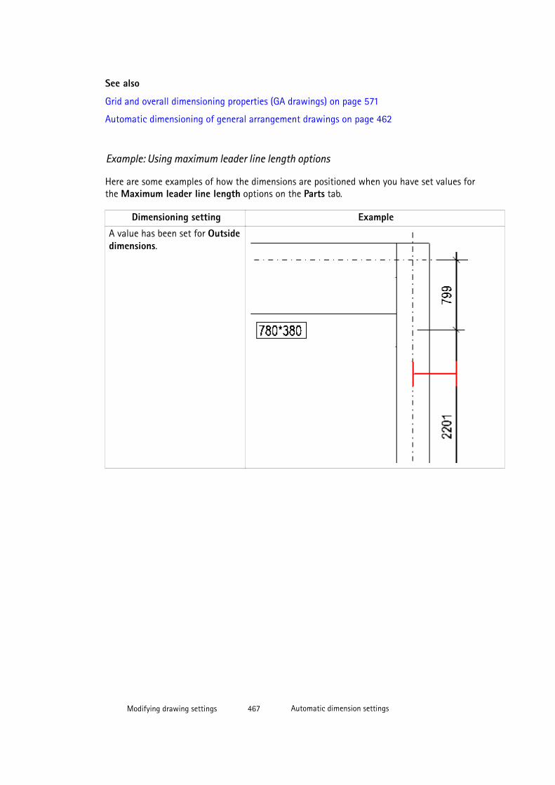
See also
Grid and overall dimensioning properties (GA drawings) on page 571
Automatic dimensioning of general arrangement drawings on page 462
Example: Using maximum leader line length options
Here are some examples of how the dimensions are positioned when you have set values forthe Maximum leader line length options on the Parts tab.
Dimensioning setting Example
A value has been set for Outsidedimensions.
Modifying drawing settings 467 Automatic dimension settings
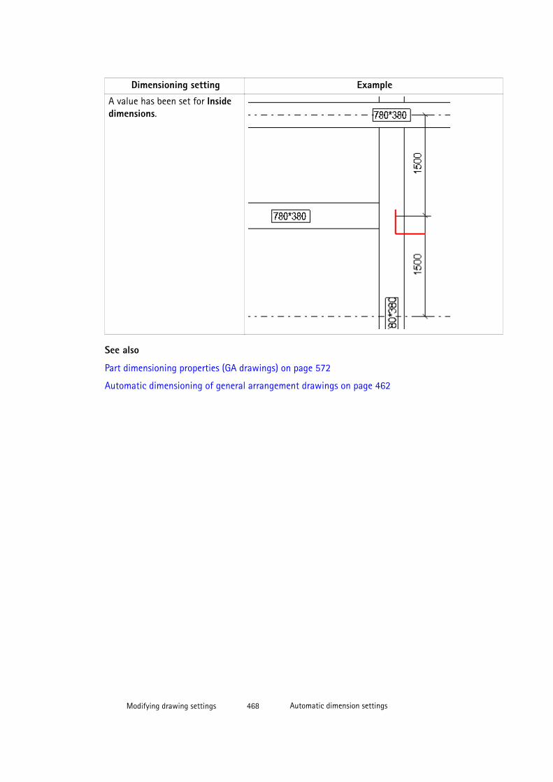
Dimensioning setting Example
A value has been set for Insidedimensions.
See also
Part dimensioning properties (GA drawings) on page 572
Automatic dimensioning of general arrangement drawings on page 462
Modifying drawing settings 468 Automatic dimension settings
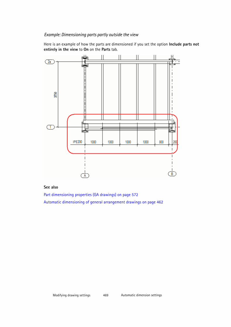
Example: Dimensioning parts partly outside the view
Here is an example of how the parts are dimensioned if you set the option Include parts notentirely in the view to On on the Parts tab.
See also
Part dimensioning properties (GA drawings) on page 572
Automatic dimensioning of general arrangement drawings on page 462
Modifying drawing settings 469 Automatic dimension settings

Example: Limiting the number of outside dimensions
Here is an example of what the part dimensions look like when you have set 3 as the valuefor the option Maximum number of outside dimensions on the Parts tab. Tekla Structureshas created three dimensions outside the grid and the fourth inside the grid.
See also
Part dimensioning properties (GA drawings) on page 572
Automatic dimensioning of general arrangement drawings on page 462
Example: Part dimension positioning
Here are some examples of how the part dimensions are positioned in general arrangementdrawings with different positioning settings selected on the Parts tab.
In the example below, Positioning is set to Inside grid, which places all dimensions next to ornear the grid.
Modifying drawing settings 470 Automatic dimension settings
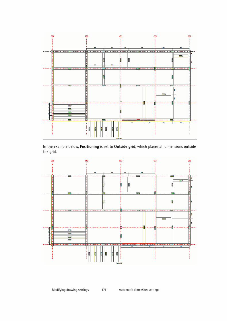
In the example below, Positioning is set to Outside grid, which places all dimensions outsidethe grid.
Modifying drawing settings 471 Automatic dimension settings
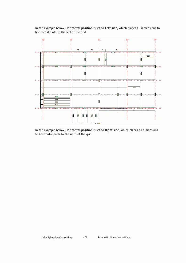
In the example below, Horizontal position is set to Left side, which places all dimensions tohorizontal parts to the left of the grid.
In the example below, Horizontal position is set to Right side, which places all dimensionsto horizontal parts to the right of the grid.
Modifying drawing settings 472 Automatic dimension settings
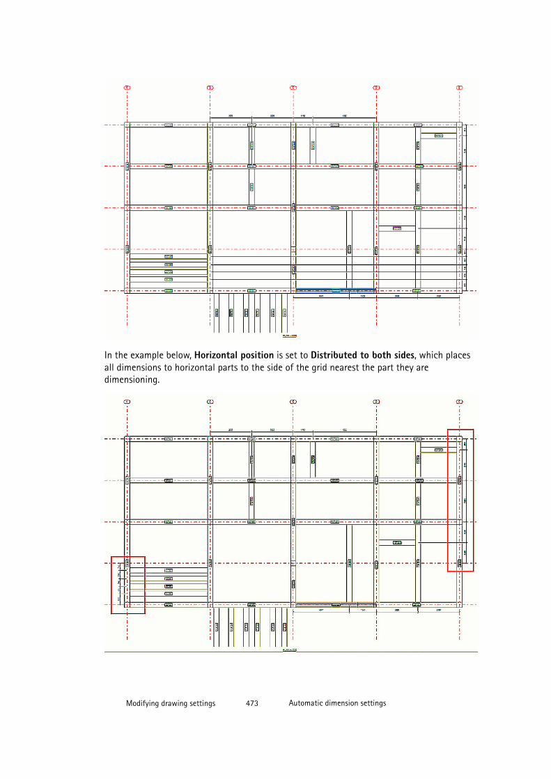
In the example below, Horizontal position is set to Distributed to both sides, which placesall dimensions to horizontal parts to the side of the grid nearest the part they aredimensioning.
Modifying drawing settings 473 Automatic dimension settings
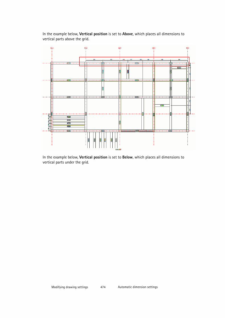
In the example below, Vertical position is set to Above, which places all dimensions tovertical parts above the grid.
In the example below, Vertical position is set to Below, which places all dimensions tovertical parts under the grid.
Modifying drawing settings 474 Automatic dimension settings
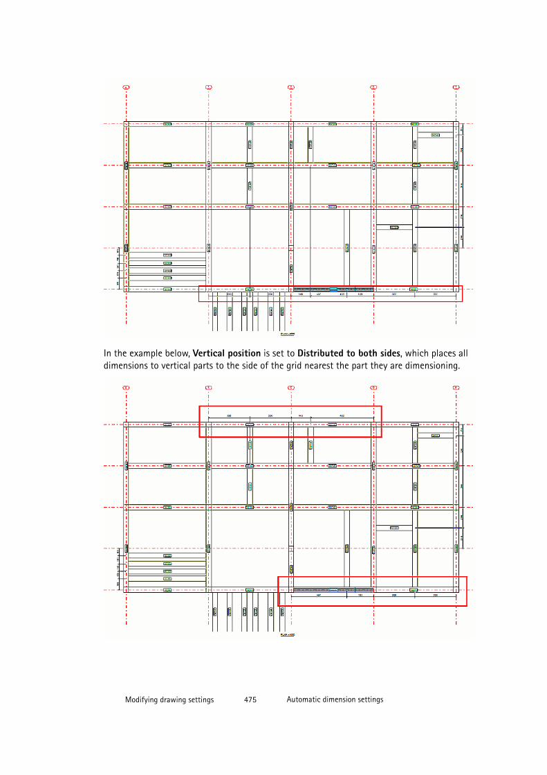
In the example below, Vertical position is set to Distributed to both sides, which places alldimensions to vertical parts to the side of the grid nearest the part they are dimensioning.
Modifying drawing settings 475 Automatic dimension settings

See also
Part dimensioning properties (GA drawings) on page 572
Automatic dimensioning of general arrangement drawings on page 462
Example: Dimensions in anchor bolt plans
Below are examples of what the dimensions in anchor bolt plans look like in differentsituations.
First an example of a typical situation, where all columns are located in grid lineintersections:
If the column reference point is not located on the grid line, Tekla Structures dimensions thereference point automatically relative to the grid lines. See the example below.
Modifying drawing settings 476 Automatic dimension settings
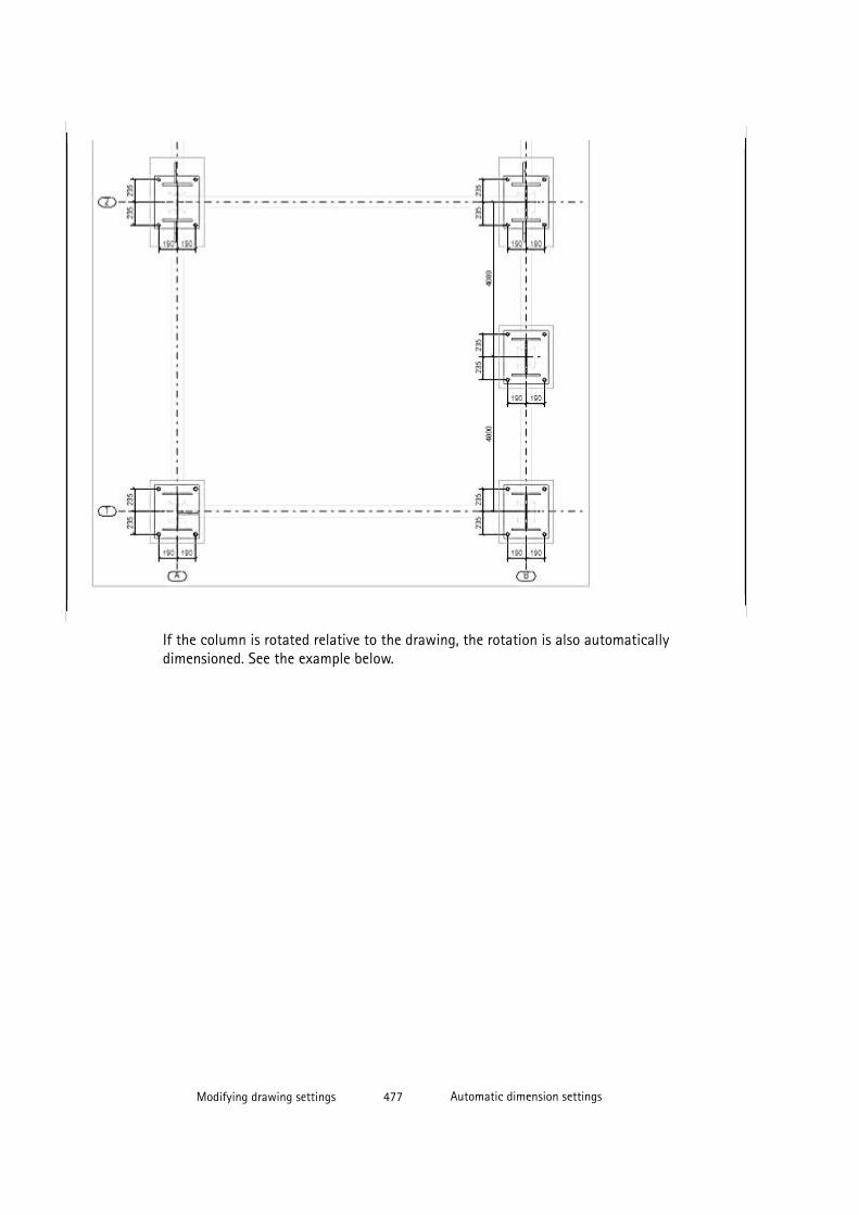
If the column is rotated relative to the drawing, the rotation is also automaticallydimensioned. See the example below.
Modifying drawing settings 477 Automatic dimension settings

If you set the advanced option XS_ANCHOR_BOLT_PLAN_USE_VIEW_COORDSYS_FOR_BOLT_DIMENSIONS to FALSE and create the drawing, all dimensions are in the drawing coordinate system.
Modifying drawing settings 478 Automatic dimension settings
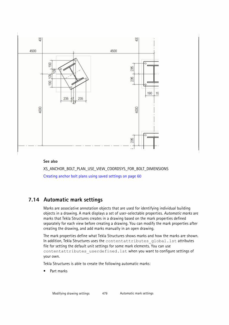
See also
XS_ANCHOR_BOLT_PLAN_USE_VIEW_COORDSYS_FOR_BOLT_DIMENSIONS
Creating anchor bolt plans using saved settings on page 60
7.14 Automatic mark settingsMarks are associative annotation objects that are used for identifying individual buildingobjects in a drawing. A mark displays a set of user-selectable properties. Automatic marks aremarks that Tekla Structures creates in a drawing based on the mark properties definedseparately for each view before creating a drawing. You can modify the mark properties aftercreating the drawing, and add marks manually in an open drawing.
The mark properties define what Tekla Structures shows marks and how the marks are shown.In addition, Tekla Structures uses the contentattributes_global.lst attributesfile for setting the default unit settings for some mark elements. You can usecontentattributes_userdefined.lst when you want to configure settings ofyour own.
Tekla Structures is able to create the following automatic marks:
• Part marks
Modifying drawing settings 479 Automatic mark settings
• Bolt marks
• Neighbor part marks
• Connection marks
• Weld marks
• Reinforcement marks
• Surface treatment marks
• Dimension marks
• View and section view label marks, and section marks
See also
Adding automatic marks on page 480
Setting the visibility of marks on page 482
Merging marks automatically on page 490
Defining contents of bolt mark Size element using advanced options on page 506
Adding level attributes in part marks on page 497
Adding user-defined attributes and template attributes in marks on page 499
Adding templates in marks on page 503
Adding symbols in marks on page 505
Adding pull-out pictures in reinforcement marks on page 509
Unit settings for marks on page 495
Mark location on page 486
Setting the appearance of mark text, frames and leader line on page 483
Mark properties on page 573
Mark elements on page 583
Object protection and placement settings in drawings on page 357
Associative annotation objects on page 180
Adding automatic marks
You can set up marks for building objects (parts, neighbor parts, bolts, surface treatment,connections, reinforcement, and neighbor reinforcement) in the view properties dialog box.You can save mark settings in a view property file for later use. For general arrangementdrawings, automatic marks are defined on drawing level.
To add automatic marks:
1. Click Drawings & Reports --> Drawing Settings and select the drawing type.
Modifying drawing settings 480 Automatic mark settings
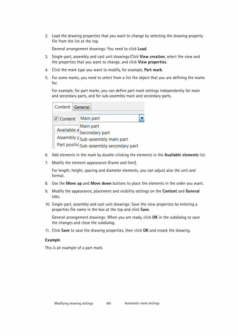
2. Load the drawing properties that you want to change by selecting the drawing propertyfile from the list at the top.
General arrangement drawings: You need to click Load.
3. Single-part, assembly and cast unit drawings:Click View creation, select the view andthe properties that you want to change, and click View properties.
4. Click the mark type you want to modify, for example, Part mark.
5. For some marks, you need to select from a list the object that you are defining the marksfor.
For example, for part marks, you can define part mark settings independently for mainand secondary parts, and for sub-assembly main and secondary parts.
6. Add elements in the mark by double-clicking the elements in the Available elements list.
7. Modify the element appearance (frame and font).
For length, height, spacing and diameter elements, you can adjust also the unit andformat.
8. Use the Move up and Move down buttons to place the elements in the order you want.
9. Modify the appearance, placement and visibility settings on the Content and Generaltabs.
10. Single-part, assembly and cast unit drawings: Save the view properties by entering aproperties file name in the box at the top and click Save.
General arrangement drawings: When you are ready, click OK in the subdialog to savethe changes and close the subdialog.
11. Click Save to save the drawing properties, then click OK and create the drawing.
Example
This is an example of a part mark.
Modifying drawing settings 481 Automatic mark settings
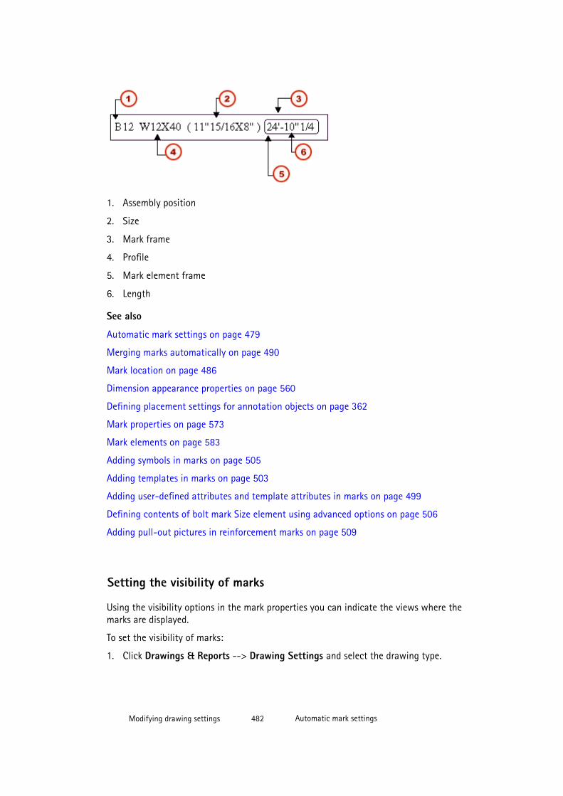
1. Assembly position
2. Size
3. Mark frame
4. Profile
5. Mark element frame
6. Length
See also
Automatic mark settings on page 479
Merging marks automatically on page 490
Mark location on page 486
Dimension appearance properties on page 560
Defining placement settings for annotation objects on page 362
Mark properties on page 573
Mark elements on page 583
Adding symbols in marks on page 505
Adding templates in marks on page 503
Adding user-defined attributes and template attributes in marks on page 499
Defining contents of bolt mark Size element using advanced options on page 506
Adding pull-out pictures in reinforcement marks on page 509
Setting the visibility of marks
Using the visibility options in the mark properties you can indicate the views where themarks are displayed.
To set the visibility of marks:
1. Click Drawings & Reports --> Drawing Settings and select the drawing type.
Modifying drawing settings 482 Automatic mark settings

2. Single-part, assembly and cast unit drawings: Click View creation, select the view andthe properties that you want to change, and click View properties.
3. Click a mark type. For example, click Part mark.
4. Go to the General (or Appearance) tab page in mark properties.
5. Select where you want to display the marks using the Visibility of marks or Visibility inview options. The available options depend on the mark type.
6. Single-part, assembly and cast unit drawings: Click Save to save the change in viewproperties.
7. Click OK.
8. Click Save to save the drawing properties, then click OK and create the drawing.
See also
Mark appearance and merging properties on page 573
Mark properties on page 573
Setting the appearance of mark text, frames and leader line
You can add frames around single mark elements and around the mark itself. You can alsoadjust the appearance of the mark text and leader line. For some elements, you can changethe unit and format.
To adjust the appearance of mark text, leader line and frames, and the unit and format forlength, height, spacing and diameter elements:
1. On the Content tab of the in mark properties, select one or several elements from theElements in mark list.
To select all elements to apply your changes in all of them, hold down Shift and click thelast element in the list.
2. Click Add frame.
3. Select a Type and Color for the frame.
You can select a different frame type and color for each element you add.
4. Select the element text Color, Font and Height.
You can select a different color, font and font height for each element you add.
5. If necessary, change the unit and the format of a length, height, spacing or diameterelement.
Before you can do this, you must first select the element from the Elements in mark list.
6. Go to the General (or the Appearance) tab and select the mark frame Type and Color.
Modifying drawing settings 483 Automatic mark settings

7. Select the Type for the leader line and the Arrow to use.
All marks do not have leader lines, in which case the leader line type selection is notavailable.
8. If you want to hide leader lines of hidden parts, set Use hidden lines for hidden parts toYes.
This option is not available for all marks.
9. Single-part, assembly and cast unit drawings: Click Save to save the view properties.
10. Click OK.
11. Click Save to save the drawing properties, then click OK and create the drawing.
See also
Additional ways for modifying part mark leader lines on page 484
Placing the base point of the reinforcement mark leader line automatically on page 485
Mark appearance and merging properties on page 573
Mark properties on page 573
Additional ways for modifying part mark leader lines
You can modify part mark leader line settings using a couple of advanced options. Click Tools--> Options --> Advanced Options and go to Marking: Parts.
To modify part mark leader line settings using advanced options:
To Do this
Define whether a leader line is drawn whenthe leader line is shorter than defined withthe advanced option XS_DRAW_SHORT_LEADER_LINES_OF_PART_MARKS_MINIMUM_LENGTH
SetXS_DRAW_SHORT_LEADER_LINES_OF_PART_MARKS to TRUE (default) to always drawleader lines in part marks. When you set thisoption to FALSE, the leader line is notdrawn if it would be shorter than theminimum you set for the advanced optionXS_DRAW_SHORT_LEADER_LINES_OF_PART_MARKS_MINIMUM_LENGTH.
Give a minimum length for the leader line. Ifthe length is less than this value, the leaderline is not drawn.
Set a value in millimeters for the advancedoptionXS_DRAW_SHORT_LEADER_LINES_OF_PART_MARKS_MINIMUM_LENGTH .
Define the leader line start position for aleader line with a rectangular frame.
Set a value for the advanced optionXS_MARK_LEADER_LINE_POSITION_TYPE_FOR_RECTANGULAR_FRAME .
Modifying drawing settings 484 Automatic mark settings
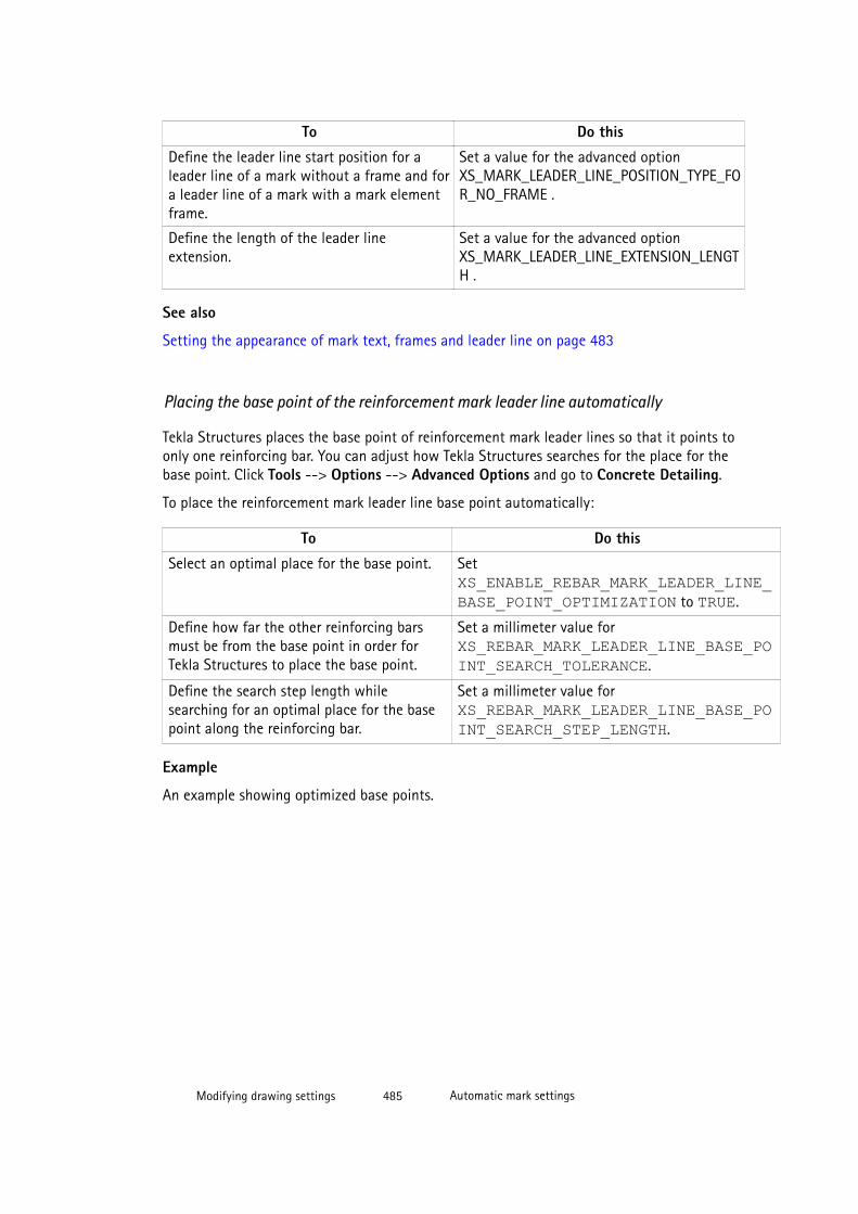
To Do this
Define the leader line start position for aleader line of a mark without a frame and fora leader line of a mark with a mark elementframe.
Set a value for the advanced optionXS_MARK_LEADER_LINE_POSITION_TYPE_FOR_NO_FRAME .
Define the length of the leader lineextension.
Set a value for the advanced optionXS_MARK_LEADER_LINE_EXTENSION_LENGTH .
See also
Setting the appearance of mark text, frames and leader line on page 483
Placing the base point of the reinforcement mark leader line automatically
Tekla Structures places the base point of reinforcement mark leader lines so that it points toonly one reinforcing bar. You can adjust how Tekla Structures searches for the place for thebase point. Click Tools --> Options --> Advanced Options and go to Concrete Detailing.
To place the reinforcement mark leader line base point automatically:
To Do this
Select an optimal place for the base point. Set XS_ENABLE_REBAR_MARK_LEADER_LINE_BASE_POINT_OPTIMIZATION to TRUE.
Define how far the other reinforcing barsmust be from the base point in order forTekla Structures to place the base point.
Set a millimeter value for XS_REBAR_MARK_LEADER_LINE_BASE_POINT_SEARCH_TOLERANCE.
Define the search step length whilesearching for an optimal place for the basepoint along the reinforcing bar.
Set a millimeter value for XS_REBAR_MARK_LEADER_LINE_BASE_POINT_SEARCH_STEP_LENGTH.
Example
An example showing optimized base points.
Modifying drawing settings 485 Automatic mark settings
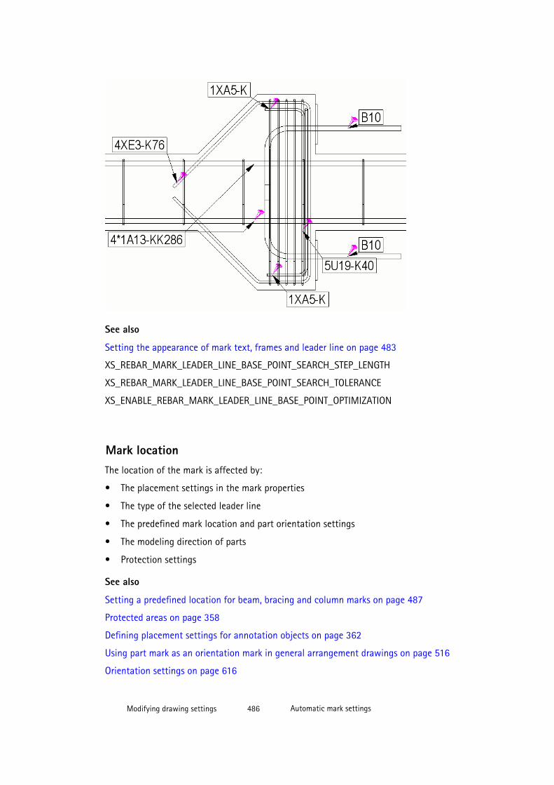
See also
Setting the appearance of mark text, frames and leader line on page 483
XS_REBAR_MARK_LEADER_LINE_BASE_POINT_SEARCH_STEP_LENGTH
XS_REBAR_MARK_LEADER_LINE_BASE_POINT_SEARCH_TOLERANCE
XS_ENABLE_REBAR_MARK_LEADER_LINE_BASE_POINT_OPTIMIZATION
Mark locationThe location of the mark is affected by:
• The placement settings in the mark properties
• The type of the selected leader line
• The predefined mark location and part orientation settings
• The modeling direction of parts
• Protection settings
See also
Setting a predefined location for beam, bracing and column marks on page 487
Protected areas on page 358
Defining placement settings for annotation objects on page 362
Using part mark as an orientation mark in general arrangement drawings on page 516
Orientation settings on page 616
Modifying drawing settings 486 Automatic mark settings
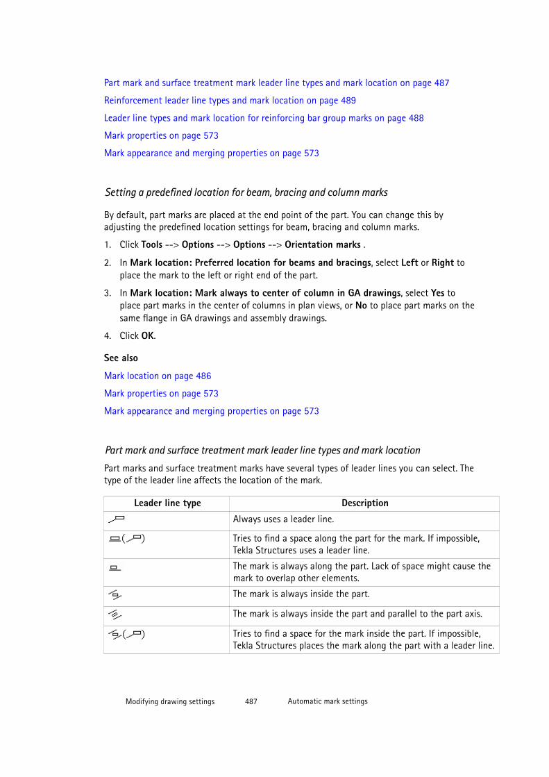
Part mark and surface treatment mark leader line types and mark location on page 487
Reinforcement leader line types and mark location on page 489
Leader line types and mark location for reinforcing bar group marks on page 488
Mark properties on page 573
Mark appearance and merging properties on page 573
Setting a predefined location for beam, bracing and column marks
By default, part marks are placed at the end point of the part. You can change this byadjusting the predefined location settings for beam, bracing and column marks.
1. Click Tools --> Options --> Options --> Orientation marks .
2. In Mark location: Preferred location for beams and bracings, select Left or Right toplace the mark to the left or right end of the part.
3. In Mark location: Mark always to center of column in GA drawings, select Yes toplace part marks in the center of columns in plan views, or No to place part marks on thesame flange in GA drawings and assembly drawings.
4. Click OK.
See also
Mark location on page 486
Mark properties on page 573
Mark appearance and merging properties on page 573
Part mark and surface treatment mark leader line types and mark location
Part marks and surface treatment marks have several types of leader lines you can select. Thetype of the leader line affects the location of the mark.
Leader line type Description
Always uses a leader line.
Tries to find a space along the part for the mark. If impossible,Tekla Structures uses a leader line.
The mark is always along the part. Lack of space might cause themark to overlap other elements.
The mark is always inside the part.
The mark is always inside the part and parallel to the part axis.
Tries to find a space for the mark inside the part. If impossible,Tekla Structures places the mark along the part with a leader line.
Modifying drawing settings 487 Automatic mark settings
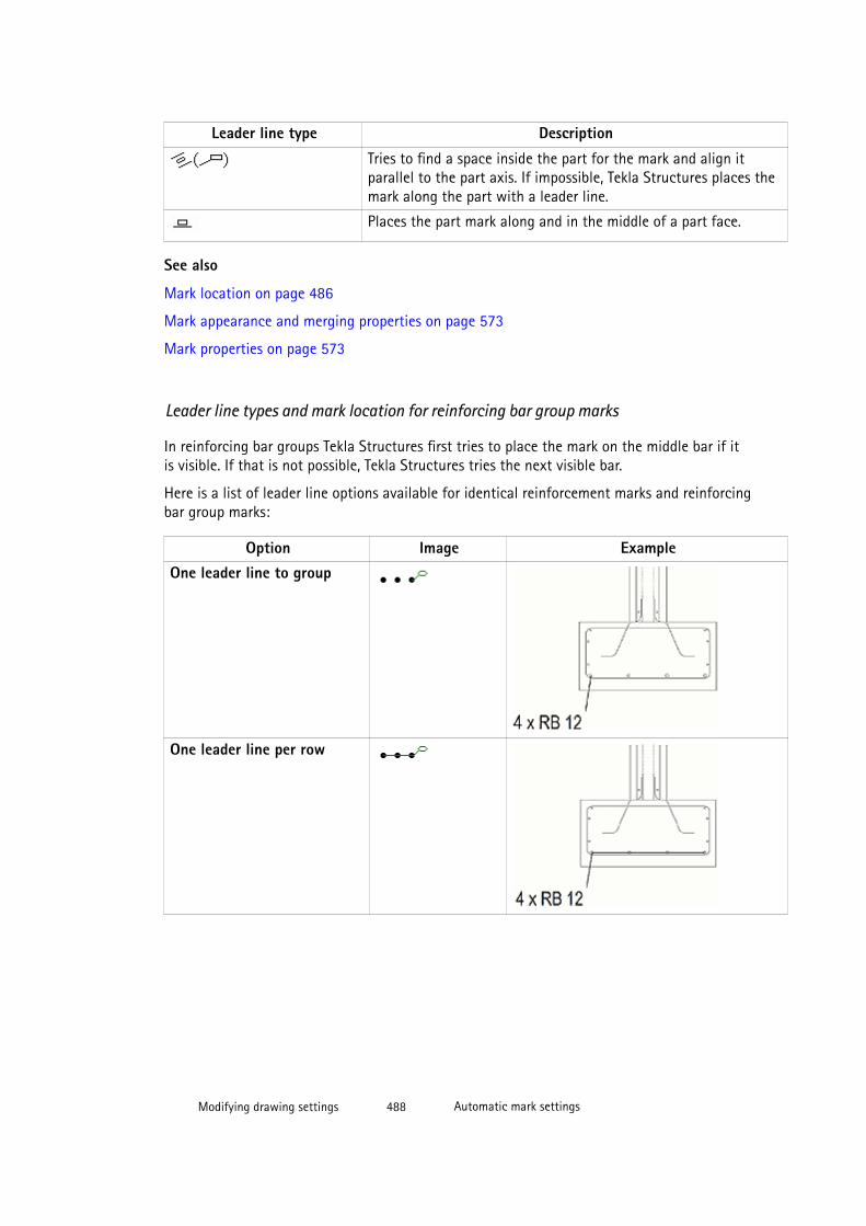
Leader line type Description
Tries to find a space inside the part for the mark and align itparallel to the part axis. If impossible, Tekla Structures places themark along the part with a leader line.
Places the part mark along and in the middle of a part face.
See also
Mark location on page 486
Mark appearance and merging properties on page 573
Mark properties on page 573
Leader line types and mark location for reinforcing bar group marks
In reinforcing bar groups Tekla Structures first tries to place the mark on the middle bar if itis visible. If that is not possible, Tekla Structures tries the next visible bar.
Here is a list of leader line options available for identical reinforcement marks and reinforcingbar group marks:
Option Image ExampleOne leader line to group
One leader line per row
Modifying drawing settings 488 Automatic mark settings
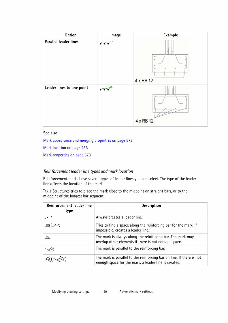
Option Image ExampleParallel leader lines
Leader lines to one point
See also
Mark appearance and merging properties on page 573
Mark location on page 486
Mark properties on page 573
Reinforcement leader line types and mark location
Reinforcement marks have several types of leader lines you can select. The type of the leaderline affects the location of the mark.
Tekla Structures tries to place the mark close to the midpoint on straight bars, or to themidpoint of the longest bar segment.
Reinforcement leader linetype
Description
Always creates a leader line.
Tries to find a space along the reinforcing bar for the mark. Ifimpossible, creates a leader line.
The mark is always along the reinforcing bar. The mark mayoverlap other elements if there is not enough space.
The mark is parallel to the reinforcing bar.
The mark is parallel to the reinforcing bar on line. If there is notenough space for the mark, a leader line is created.
Modifying drawing settings 489 Automatic mark settings
See also
Mark location on page 486
Setting the appearance of mark text, frames and leader line on page 483
Mark appearance and merging properties on page 573
Mark properties on page 573
Merging marks automaticallyYou can let Tekla Structures automatically merge marks.
You can automatically merge part marks, surface treatment marks and reinforcement marks.
See also
Merging part marks on page 492
Merged reinforcement marks on page 493
Merging reinforcement marks automatically on page 493
Merging marks on page 189
Merged part marks
A merged part mark means that only one part mark is used for similar parts in a drawing.Merged part marks indicate the number of included parts, and contain the specified partmark contents, and the near side and far side information. The marks are merged only in xdirection of the main part.
Tekla Structures merges marks for visible parts in drawings if:
• The secondary parts are welded or bolted to the same main part.
• The parts are on the same line.
• Distances between the parts are equal.
• The parts have the same part position.
• Distance between parts is not more than what is set for the advanced option XS_PART_MERGE_MAX_DISTANCE.
• There are at least as many parts in the array as it has been set for the advanced option XS_MIN_MERGE_PART_COUNT.
Limitations
• Part marks can be merged only on view and drawing level. It is not possible to merge orsplit part marks manually.
• Tekla Structures does not merge neighbor part marks.
Modifying drawing settings 490 Automatic mark settings
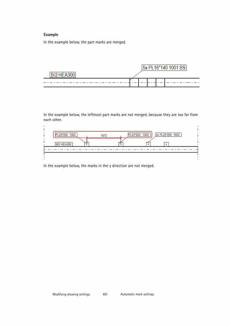
Example
In the example below, the part marks are merged.
In the example below, the leftmost part marks are not merged, because they are too far fromeach other.
In the example below, the marks in the y direction are not merged.
Modifying drawing settings 491 Automatic mark settings

See also
Merging part marks on page 492
Merging part marks
You can merge part marks automatically to reduce the number of marks in the drawing.
To merge part marks automatically:
1. On the General tab in the part mark properties, set Merge marks to On.
2. Single-part, assembly and cast unit drawings: Click Save to save the changes in viewproperties and OK to return to drawing properties.
General arrangement drawings: Click OK.
3. Click Save to save the drawing properties, then click OK and create the drawing.
This setting merges marks for identical secondary parts on both faces of main parts.
See also
Merged part marks on page 490
Mark appearance and merging properties on page 573
Modifying drawing settings 492 Automatic mark settings

XS_MULTIPLIER_SEPARATOR_FOR_MERGED_PART_MARK
XS_NSFS_POSTFIX_FOR_MERGED_PART_MARK
XS_NS_POSTFIX_FOR_MERGED_PART_MARK
XS_FS_POSTFIX_FOR_MERGED_PART_MARK
XS_PART_MERGE_MAX_DISTANCE
XS_MIN_MERGE_PART_COUNT
Merged reinforcement marks
Tekla Structures can automatically merge similar reinforcement marks of bars. Merged marksmay include several blocks, and additional information. Blocks combine similar single marks.
NOTE To have Tekla Structures automatically merge reinforcement marks in drawings, thereinforcement must be attached to a concrete part or cast unit in the model.
Tekla Structures automatically merges marks for visible reinforcing bars in drawings if:
• The bars belong to the same concrete part or cast unit.
• The direction of the bars is the same.
• The bar marks are identical.
• The bars are close to each other.
• A straight line can be drawn through all the bars.
You can also define the distance within which to automatically merge marks for visiblereinforcing bars using advanced options.
See also
Merging reinforcement marks manually on page 189
Merging reinforcement marks automatically on page 493
Merging reinforcement marks automatically
1. Go to the Merging tab of the Cast Unit - Reinforcement Marks dialog box.
2. Select an option from the Identical marks in same cast unit list to merge marks andcreate leader lines.
3. If there are several possible merge directions, select the direction from Preferreddirection of merge.
4. Select the contents to be included in the merged reinforcement marks from the Availableelements list.
NOTE To ensure that merged reinforcement marks appear in the drawing, alwaysinclude Symbol separating blocks in mark as the last element in the
Modifying drawing settings 493 Automatic mark settings

reinforcement mark. To omit the separating symbol, leave this box blank, but stillinclude the element in the mark.
5. If needed, add a frame around the single elements in the mark. You can define the frameindividually for each element.
6. Adjust the font, font height and the color of the mark text. You can adjust these settingsindividually for each element.
7. Click OK.
Example
In this example, we merge three A φ12 L2000 marks to a block, and six V φ8 L650 marks toanother block, and then merge them in the following way:
Single mark content
Symbol separating the blocks
Block prefix
Distance between groups
Block 1
Block 2
See also
Mark appearance and merging properties on page 573
Showing mark frames and leader lines for hidden parts
If a part is behind another part in the drawing so that it is hidden, you can select to show themark frame and leader line of the hidden part with a dashed or a solid line.
To set the mark frame and leader line appearance for the part marks of hidden parts:
Modifying drawing settings 494 Automatic mark settings
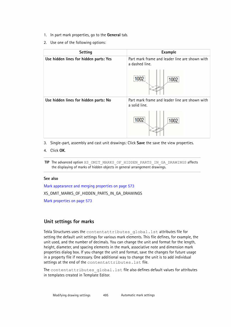
1. In part mark properties, go to the General tab.
2. Use one of the following options:
Setting Example
Use hidden lines for hidden parts: Yes Part mark frame and leader line are shown witha dashed line.
Use hidden lines for hidden parts: No Part mark frame and leader line are shown witha solid line.
3. Single-part, assembly and cast unit drawings: Click Save the save the view properties.
4. Click OK.
TIP The advanced option XS_OMIT_MARKS_OF_HIDDEN_PARTS_IN_GA_DRAWINGS affectsthe displaying of marks of hidden objects in general arrangement drawings.
See also
Mark appearance and merging properties on page 573
XS_OMIT_MARKS_OF_HIDDEN_PARTS_IN_GA_DRAWINGS
Mark properties on page 573
Unit settings for marks
Tekla Structures uses the contentattributes_global.lst attributes file forsetting the default unit settings for various mark elements. This file defines, for example, theunit used, and the number of decimals. You can change the unit and format for the length,height, diameter, and spacing elements in the mark, associative note and dimension markproperties dialog box. If you change the unit and format, save the changes for future usagein a property file if necessary. One additional way to change the unit is to add individualsettings at the end of the contentattributes.lst file.
The contentattributes_global.lst file also defines default values for attributesin templates created in Template Editor.
Modifying drawing settings 495 Automatic mark settings
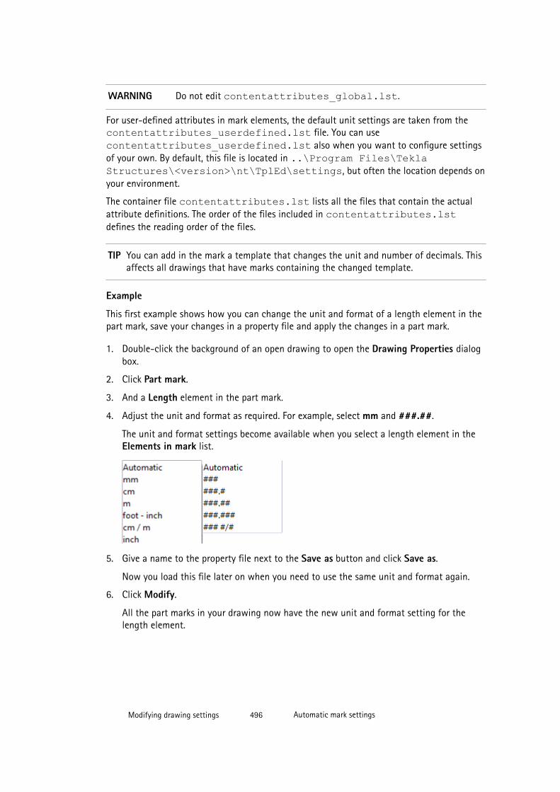
WARNING Do not edit contentattributes_global.lst.
For user-defined attributes in mark elements, the default unit settings are taken from thecontentattributes_userdefined.lst file. You can usecontentattributes_userdefined.lst also when you want to configure settingsof your own. By default, this file is located in ..\Program Files\TeklaStructures\<version>\nt\TplEd\settings, but often the location depends onyour environment.
The container file contentattributes.lst lists all the files that contain the actualattribute definitions. The order of the files included in contentattributes.lstdefines the reading order of the files.
TIP You can add in the mark a template that changes the unit and number of decimals. Thisaffects all drawings that have marks containing the changed template.
Example
This first example shows how you can change the unit and format of a length element in thepart mark, save your changes in a property file and apply the changes in a part mark.
1. Double-click the background of an open drawing to open the Drawing Properties dialogbox.
2. Click Part mark.
3. And a Length element in the part mark.
4. Adjust the unit and format as required. For example, select mm and ###.##.
The unit and format settings become available when you select a length element in theElements in mark list.
5. Give a name to the property file next to the Save as button and click Save as.
Now you load this file later on when you need to use the same unit and format again.
6. Click Modify.
All the part marks in your drawing now have the new unit and format setting for thelength element.
Modifying drawing settings 496 Automatic mark settings
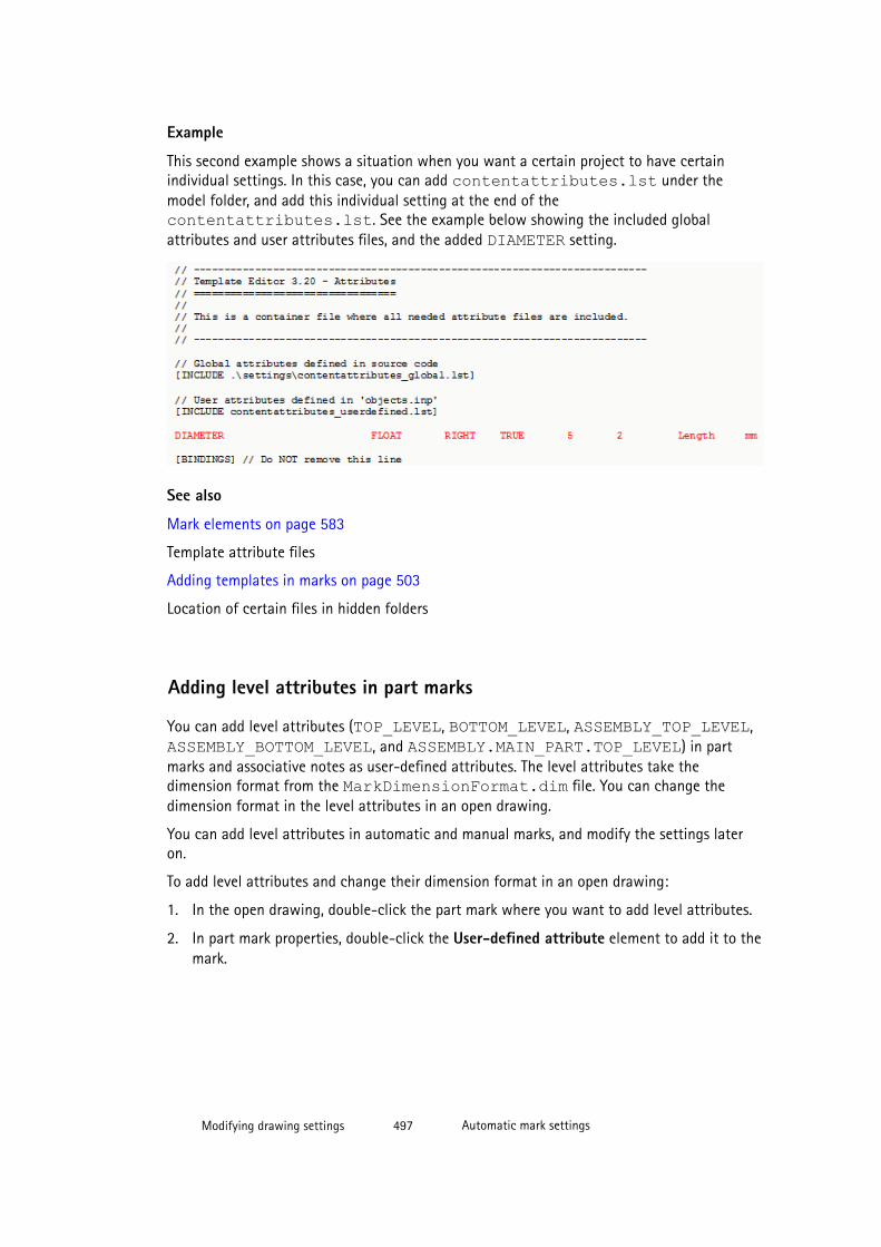
Example
This second example shows a situation when you want a certain project to have certainindividual settings. In this case, you can add contentattributes.lst under themodel folder, and add this individual setting at the end of thecontentattributes.lst. See the example below showing the included globalattributes and user attributes files, and the added DIAMETER setting.
See also
Mark elements on page 583
Template attribute files
Adding templates in marks on page 503
Location of certain files in hidden folders
Adding level attributes in part marks
You can add level attributes (TOP_LEVEL, BOTTOM_LEVEL, ASSEMBLY_TOP_LEVEL, ASSEMBLY_BOTTOM_LEVEL, and ASSEMBLY.MAIN_PART.TOP_LEVEL) in partmarks and associative notes as user-defined attributes. The level attributes take thedimension format from the MarkDimensionFormat.dim file. You can change thedimension format in the level attributes in an open drawing.
You can add level attributes in automatic and manual marks, and modify the settings lateron.
To add level attributes and change their dimension format in an open drawing:
1. In the open drawing, double-click the part mark where you want to add level attributes.
2. In part mark properties, double-click the User-defined attribute element to add it to themark.
Modifying drawing settings 497 Automatic mark settings
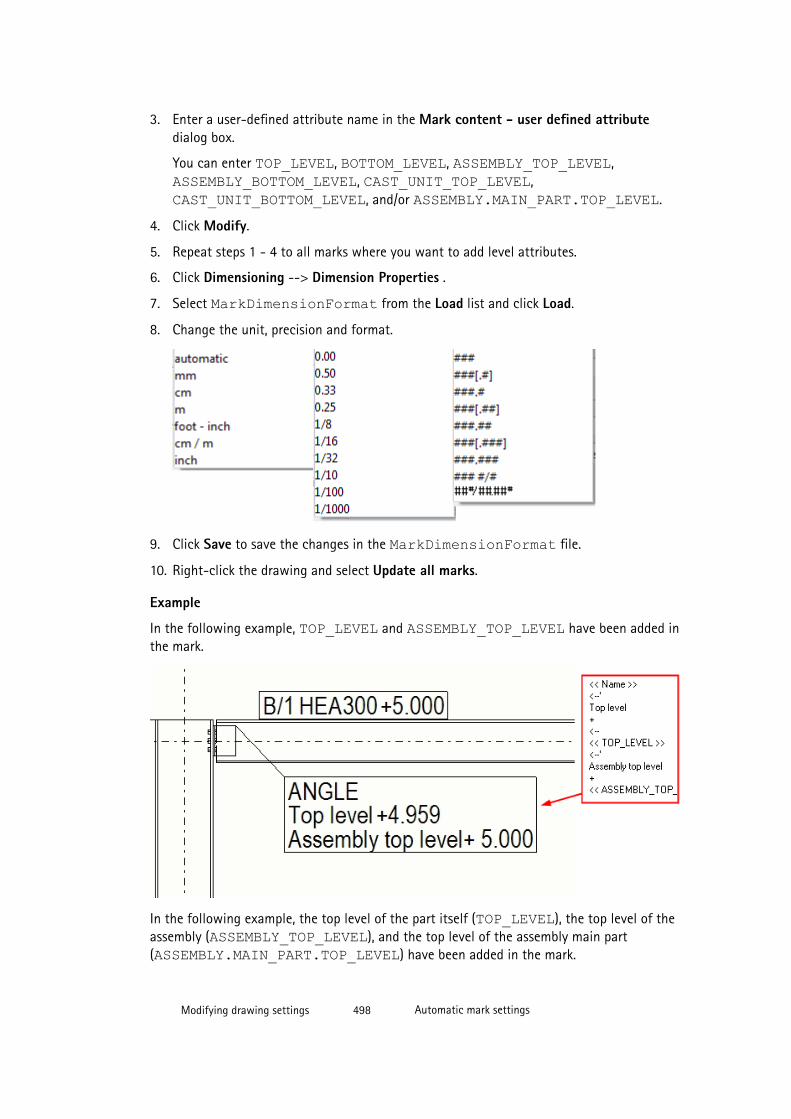
3. Enter a user-defined attribute name in the Mark content - user defined attributedialog box.
You can enter TOP_LEVEL, BOTTOM_LEVEL, ASSEMBLY_TOP_LEVEL, ASSEMBLY_BOTTOM_LEVEL, CAST_UNIT_TOP_LEVEL, CAST_UNIT_BOTTOM_LEVEL, and/or ASSEMBLY.MAIN_PART.TOP_LEVEL.
4. Click Modify.
5. Repeat steps 1 - 4 to all marks where you want to add level attributes.
6. Click Dimensioning --> Dimension Properties .
7. Select MarkDimensionFormat from the Load list and click Load.
8. Change the unit, precision and format.
9. Click Save to save the changes in the MarkDimensionFormat file.
10. Right-click the drawing and select Update all marks.
Example
In the following example, TOP_LEVEL and ASSEMBLY_TOP_LEVEL have been added inthe mark.
In the following example, the top level of the part itself (TOP_LEVEL), the top level of theassembly (ASSEMBLY_TOP_LEVEL), and the top level of the assembly main part(ASSEMBLY.MAIN_PART.TOP_LEVEL) have been added in the mark.
Modifying drawing settings 498 Automatic mark settings

See also
TOP_LEVEL
BOTTOM_LEVEL
ASSEMBLY_BOTTOM_LEVEL
ASSEMBLY_TOP_LEVEL
Adding user-defined attributes and template attributes in marks on page 499
Adding user-defined attributes and template attributes in marks
All types of building object marks allow you to add user-defined attributes and templateattributes. For example, you might want to add control numbers or specify the number ofcharacters in part numbers in assembly or part marks.
You can add user-defined attributes in automatic and manual marks.
To add a user-defined attribute in a building object mark:
1. In the mark properties dialog box, double-click the User-defined attribute element toadd it to the mark.
2. Enter the user-defined attribute name in the Mark content - user defined attributedialog box exactly as it appears in the objects.inp file.
You can also enter a template attribute.
Modifying drawing settings 499 Automatic mark settings
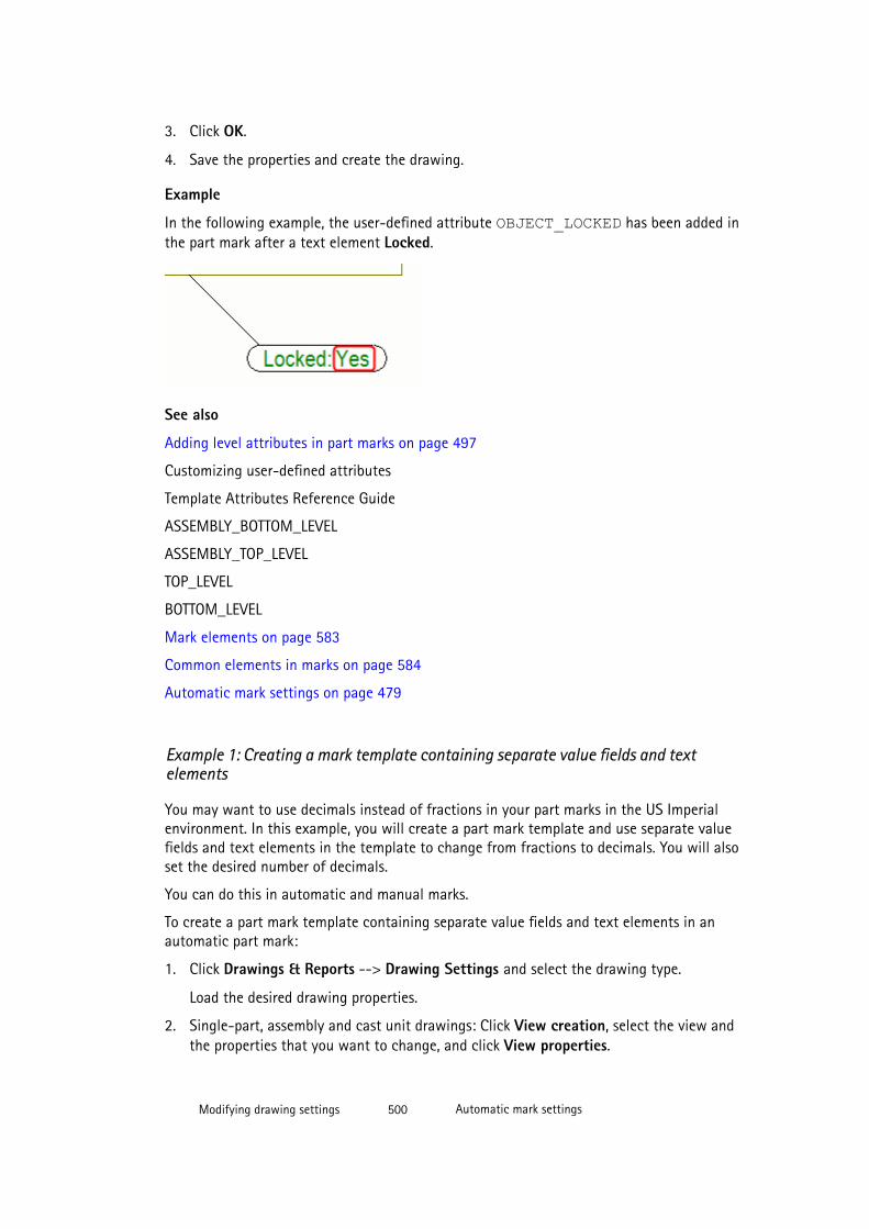
3. Click OK.
4. Save the properties and create the drawing.
Example
In the following example, the user-defined attribute OBJECT_LOCKED has been added inthe part mark after a text element Locked.
See also
Adding level attributes in part marks on page 497
Customizing user-defined attributes
Template Attributes Reference Guide
ASSEMBLY_BOTTOM_LEVEL
ASSEMBLY_TOP_LEVEL
TOP_LEVEL
BOTTOM_LEVEL
Mark elements on page 583
Common elements in marks on page 584
Automatic mark settings on page 479
Example 1: Creating a mark template containing separate value fields and textelements
You may want to use decimals instead of fractions in your part marks in the US Imperialenvironment. In this example, you will create a part mark template and use separate valuefields and text elements in the template to change from fractions to decimals. You will alsoset the desired number of decimals.
You can do this in automatic and manual marks.
To create a part mark template containing separate value fields and text elements in anautomatic part mark:
1. Click Drawings & Reports --> Drawing Settings and select the drawing type.
Load the desired drawing properties.
2. Single-part, assembly and cast unit drawings: Click View creation, select the view andthe properties that you want to change, and click View properties.
Modifying drawing settings 500 Automatic mark settings

3. Click Part mark.
4. Double-click Template in the Available elements list.
5. In the Mark content - template dialog box, click Create new....
This starts the Template Editor.
6. Click File --> New and create a new graphical template.
7. Click Insert --> Component --> Row .
8. Select PART as the content type.
9. Click Insert --> Text , enter L and place it inside the row you just added.
10. Click Insert --> Value field and place the value field on the right side of the L text.
11. In the displayed Select Attribute [Part] dialog box, scroll down to PROFILE - Profile,open the profile tree, select the HEIGHT - height property and click OK.
12. Double-click the value field. In the Value Field Properties dialog box, change thesettings as follows:
• Unit: inch• Decimals: 1• Length: 8
13. Click OK.
14. Click Insert --> Text , enter X as text and place it on the right side of the value field.
15. Repeat steps 8–11 to add another value field for the width information (WIDTH - Widthprofile property).
16. Click Insert --> Text and add the second X between the value fields.
17. Add the third value field for the profile flange thickness by selectingFLANGE_THICKNESS_1 - Flange thickness 1 profile property and modify the settingsas follows:
• Unit: inch• Decimals: 2• Length: 4
18. Click Edit --> Properties... and minimize the height and the width of the row.
19. Click File --> Save to save the template.
The template is by default saved as a .tpl file in the \mark folder under the modelfolder. You can copy this template to other models as required.
20. In Tekla Structures, click Refresh list in the Mark content - template dialog box to seethe template you created.
21. Select the template and click OK.
Modifying drawing settings 501 Automatic mark settings
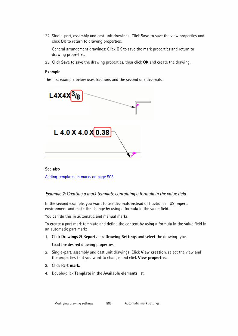
22. Single-part, assembly and cast unit drawings: Click Save to save the view properties andclick OK to return to drawing properties.
General arrangement drawings: Click OK to save the mark properties and return todrawing properties.
23. Click Save to save the drawing properties, then click OK and create the drawing.
Example
The first example below uses fractions and the second one decimals.
See also
Adding templates in marks on page 503
Example 2: Creating a mark template containing a formula in the value field
In the second example, you want to use decimals instead of fractions in US Imperialenvironment and make the change by using a formula in the value field.
You can do this in automatic and manual marks.
To create a part mark template and define the content by using a formula in the value field inan automatic part mark:
1. Click Drawings & Reports --> Drawing Settings and select the drawing type.
Load the desired drawing properties.
2. Single-part, assembly and cast unit drawings: Click View creation, select the view andthe properties that you want to change, and click View properties.
3. Click Part mark.
4. Double-click Template in the Available elements list.
Modifying drawing settings 502 Automatic mark settings
5. In the Mark content - template dialog box, click Create new....
This starts the Template Editor.
6. Click File --> New and create a new graphical template.
7. Click Insert --> Component --> Row .
8. Select PART as the content type.
9. Click Insert --> Value field , and place the field.
10. In the displayed Select Attribute [Part] dialog box, click the Formula... button.
11. Add the following formula in the Formula box and click OK:
"L " + format(GetValue("HEIGHT"),"Length","inch",1) + " x"+ format(GetValue("WIDTH"),"Length","inch",1) + " x " +format(GetValue("PROFILE.FLANGE_THICKNESS_1"),"Length","inch",2)
12. Double-click the value field to open the Value Field Properties dialog box.
13. Set the Data type to text, enter a name for the field, for example, PART_MARK, andensure that the length value you give in the Length field is high enough to fit all thecharacters and numbers included, for example, 20.
14. Click OK.
15. Click Edit --> Properties and minimize the height and the width of the row.
16. Click File --> Save to save the template.
The template is by default saved as a .tpl file in the \mark folder under the modelfolder. You can copy this template to other models as required.
17. In Tekla Structures, click Refresh list in the Mark content - template dialog box to seethe template you created.
18. Select the template and click OK.
19. Single-part, assembly and cast unit drawings: Click Save to save the view properties andclick OK to return to drawing properties.
General arrangement drawings: Click OK to save the mark properties and return todrawing properties.
20. Click Save to save the drawing properties, then click OK and create the drawing.
See also
Example 1: Creating a mark template containing separate value fields and text elements onpage 500
Adding templates in marks on page 503
Modifying drawing settings 503 Automatic mark settings

Adding templates in marksYou can create custom graphical templates (.tpl) with Template Editor and add them aselements in all types of marks and associative notes. In the mark templates, you can includedetailed information of an embed or assembly, such as the submaterial used. Or you can usea template that changes the unit and the number of decimals in measurement values in amark. You can also add graphical objects using the Template Editor tools in your marktemplates. You can use templates in marks and associative notes in all drawing types.
Before you add a template in a mark, ensure that the template you use does not contain anymargins.
The size of the templates in part marks is calculated according to the actual size of templatecontents. Only lines and texts in the template are considered when calculating the exact size.This means, for example, that circles or bitmaps in the template do not have any effect.
To add a template in a mark:
1. Click Drawings & Reports --> Drawing Settings and select the drawing type.
2. Load the drawing properties that you want to change.
General arrangement drawings: You need to click Load.
3. Single-part, assembly and cast unit drawings: Click View creation, select the view andthe properties that you want to change, and click View properties.
4. Click the mark type that you want to change.
For example, click Part mark.
5. In the mark properties dialog box, double-click the Template element in the availableelements list to add it in the mark.
This will remove all other elements from the mark.
6. Select a template from the list in the Mark content - template dialog box. If you havenot created a template yet, or want to edit the template, you can do it from here.
Remember that if you edit the template here, the change affects all drawings that havemarks containing the changed template.
7. Click OK.
8. Single-part, assembly and cast unit drawings: Save the view properties by clicking Saveand click OK to return to drawing properties.
General arrangement drawings: Click OK to save the mark properties and return todrawing properties.
9. Click Save to save the drawing properties, then click OK and create the drawing.
10. When necessary, place the saved mark attribute files from the \attribute folder intoyour firm folder.
TIP The mark templates are by default searched from the following folders in the following order:
%XS_TEMPLATE_DIRECTORY%\mark
Modifying drawing settings 504 Automatic mark settings
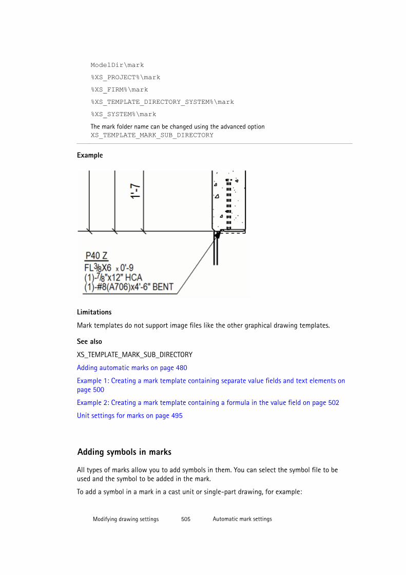
ModelDir\mark%XS_PROJECT%\mark%XS_FIRM%\mark%XS_TEMPLATE_DIRECTORY_SYSTEM%\mark%XS_SYSTEM%\markThe mark folder name can be changed using the advanced option XS_TEMPLATE_MARK_SUB_DIRECTORY
Example
Limitations
Mark templates do not support image files like the other graphical drawing templates.
See also
XS_TEMPLATE_MARK_SUB_DIRECTORY
Adding automatic marks on page 480
Example 1: Creating a mark template containing separate value fields and text elements onpage 500
Example 2: Creating a mark template containing a formula in the value field on page 502
Unit settings for marks on page 495
Adding symbols in marks
All types of marks allow you to add symbols in them. You can select the symbol file to beused and the symbol to be added in the mark.
To add a symbol in a mark in a cast unit or single-part drawing, for example:
Modifying drawing settings 505 Automatic mark settings

1. Click Drawings & Reports --> Drawing Settings and select the drawing type.
2. Load the drawing properties that you want to change.
3. Click View creation, select the view and the properties that you want to change, andclick View properties.
4. In the options tree, click the mark type that you want to change.
For example, click Part mark.
5. In mark properties, double-click Symbol in the Available elements list.
6. In the Mark content - Symbol dialog box, click Select next to the File box to select thesymbol file you want to use.
7. When you have selected the file, click Select next to the Number box to select thenumber of the symbol you want to use.
8. Click OK.
Tekla Structures adds the name of the symbol file and the number of the symbol in theelements list.
9. Save the view properties by clicking Save and click OK to return to the drawingproperties panel.
10. Save the drawing properties by clicking Save, click OK and create the drawing.
See also
Symbols in drawings on page 243
Automatic mark settings on page 479
Defining contents of bolt mark Size element using advanced options
You can use a couple of advanced options to define the contents of the bolt mark Sizeelement in different types of drawings in Tools --> Options --> Advanced Options -->Marking: Bolts .
NOTE • Note that general arrangement drawings have separate advanced options.
• Any changes made to the advanced options listed in the table below will takeplace only in the new drawings you create and if you modify the affected boltmarks.
To define the contents for a bolt mark size element:
Modifying drawing settings 506 Automatic mark settings

To Do this
Define the contents of the sizeelement in slotted hole marks orlonghole marks (generalarrangement drawings).
Set a value for the advanced option XS_LONGHOLE_MARK_STRING_FOR_SIZE.
Set a value for the advanced option XS_LONGHOLE_MARK_STRING_FOR_SIZE_IN_GA.
Define the contents of the sizeelement in slotted hole marks orlonghole marks (generalarrangement drawings) for sitebolts.
Set a value for the advanced option XS_SITE_LONGHOLE_MARK_STRING_FOR_SIZE.
Set a value for the advanced option XS_SITE_LONGHOLE_MARK_STRING_FOR_SIZE_IN_GA.
Define the contents of the sizeelement in slotted hole marks orlonghole marks (generalarrangement drawings) forworkshop bolts.
Set a value for the advanced option XS_SHOP_LONGHOLE_MARK_STRING_FOR_SIZE.
Set a value for the advanced option XS_SHOP_LONGHOLE_MARK_STRING_FOR_SIZE_IN_GA.
Define the contents of the sizeelement in hole marks.
Set a value for the advanced option XS_HOLE_MARK_STRING_FOR_SIZE.
Set a value for the advanced option XS_HOLE_MARK_STRING_FOR_SIZE_IN_GA.
Define the contents of the sizeelement in hole marks for site bolts.
Set a value for the advanced option XS_SITE_HOLE_MARK_STRING_FOR_SIZESet a value for the advanced option XS_SITE_HOLE_MARK_STRING_FOR_SIZE_IN_GA
Define the contents of the sizeelement in hole marks for workshopbolts.
Set a value for the advanced option XS_SHOP_HOLE_MARK_STRING_FOR_SIZESet a value for the advanced option XS_SHOP_HOLE_MARK_STRING_FOR_SIZE_IN_GA
Define the contents of the sizeelement in bolt marks.
Set a value for the advanced option XS_BOLT_MARK_STRING_FOR_SIZESet a value for the advanced option XS_BOLT_MARK_STRING_FOR_SIZE_IN_GA
Define the contents of the sizeelement in bolt marks for site bolts.
Set a value for the advanced option XS_SITE_BOLT_MARK_STRING_FOR_SIZESet a value for the advanced option XS_SITE_BOLT_MARK_STRING_FOR_SIZE_IN_GA
Define the contents of the sizeelement in bolt marks for workshopbolts.
Set a value for the advanced option XS_SHOP_BOLT_MARK_STRING_FOR_SIZESet a value for the advanced option XS_SHOP_BOLT_MARK_STRING_FOR_SIZE_IN_GA
Modifying drawing settings 507 Automatic mark settings
You can use any combination of text and the following options as the value for the aboveadvanced options. Enclose each option in % characters. To use special characters enter abackslash (\) followed by an ASCII number. You can use the options in any order, and makecalculations.
• BOLT_NUMBER• DIAMETER• LENGTH• HOLE.DIAMETER• LONG_HOLE_X• LONG_HOLE_Y• LONGHOLE_MIN (the shorter of the slotted hole dimensions)
• LONGHOLE_MAX (the longer of the slotted hole dimensions)
• BOLT_STANDARD• BOLT_MATERIAL• BOLT_ASSEMBLY_TYPE• BOLT_COUNTERSUNK• BOLT_SHORT_NAME• BOLT_FULL_NAME
Example
Example of using the advanced options:
XS_LONGHOLE_MARK_STRING_FOR_SIZE=D%HOLE.DIAMETER%(%HOLE.DIAMETER+LONG_HOLE_X%x%HOLE.DIAMETER+LONG_HOLE_Y%)XS_SITE_HOLE_MARK_STRING_FOR_SIZE=D%HOLE.DIAMETER%Please note that for calculations the operator (+, -, *, /) must not be outside the "%" marks:
Correct: %OPTION1*OPTION2%Incorrect: %OPTION1%*%OPTION2%For example, if OPTION1 = 5.0 and OPTION2 = 3.0, the results would be "15" and "5*3"
See also
Bolt mark elements on page 586
Modifying drawing settings 508 Automatic mark settings

Adding pull-out pictures in reinforcement marks
To illustrate the shape and dimensions of a reinforcing bar in a drawing, you can add a pull-out picture of the bar in the reinforcement mark.
Pull-out pictures can be added in automatic and manually created marks.
To add pull-out picture in an automatic mark in a cast unit drawing:
1. Click Drawings & Reports --> Drawing Settings and select the drawing type.
2. Load the drawing properties that you want to change.
3. Click View creation, select the view and the properties that you want to change, andclick View properties.
4. Click Reinforcement mark.
5. In the Cast Unit - Reinforcement Mark Properties dialog box, double-click the Pulloutpicture element in the Available elements list to add it to the reinforcement mark.
6. In the Pullout picture dialog box, select the scaling option in Scale by:
• Auto autoscales the pull-out.
• One factor and Two factors scale the pull-out according to the values that youenter.
The scale of the pull-out is relative to the scale of the drawing view. For example, ifthe drawing view scale is 1/10 and the pull-out scaling is 2, the actual scale of thepull-out in the drawing view is 1/5.
7. In Rotation, select the rotation of the pull-out: Automatic, Plane or 3D. If the pull-outis 3D, and you select Automatic, Tekla Structures automatically shows the pull-out in 3D.
8. In End marks, define the shape of bar ends in the pull-out.
9. Select Dimensions to show bar dimensions in the pull-out.
10. Select Exaggeration to show reinforcing bar hooks more clearly in the pull-out.
11. Select Bending radius to show the bending radius of the reinforcing bar.
12. Select Bending angle to show bar bending angles in the pull-out.
13. Click OK.
14. Click Save to save the view properties and OK to return to drawing properties.
15. Click Save to save the drawing properties, then click OK and create the drawing.
Modifying drawing settings 509 Automatic mark settings
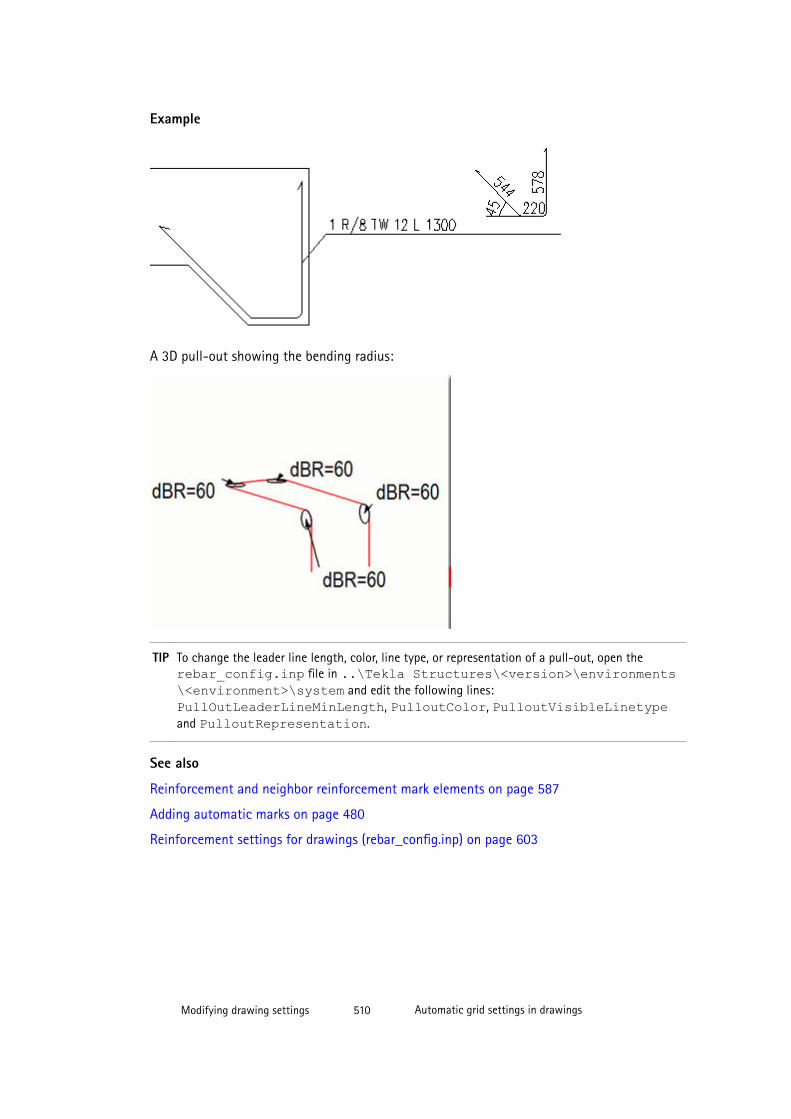
Example
A 3D pull-out showing the bending radius:
TIP To change the leader line length, color, line type, or representation of a pull-out, open therebar_config.inp file in ..\Tekla Structures\<version>\environments\<environment>\system and edit the following lines: PullOutLeaderLineMinLength, PulloutColor, PulloutVisibleLinetypeand PulloutRepresentation.
See also
Reinforcement and neighbor reinforcement mark elements on page 587
Adding automatic marks on page 480
Reinforcement settings for drawings (rebar_config.inp) on page 603
Modifying drawing settings 510 Automatic grid settings in drawings
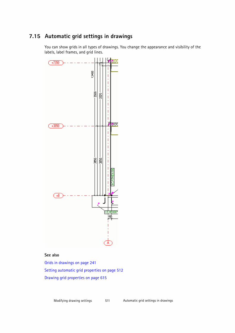
7.15 Automatic grid settings in drawings
You can show grids in all types of drawings. You change the appearance and visibility of thelabels, label frames, and grid lines.
See also
Grids in drawings on page 241
Setting automatic grid properties on page 512
Drawing grid properties on page 615
Modifying drawing settings 511 Automatic grid settings in drawings
Setting automatic grid properties
You can modify drawing grid properties of single-part, assembly and cast unit drawingsindividually for each view. In general arrangement drawings, you can modify the gridproperties on both view and drawing level. You can also modify individual grid properties ofin an open drawing.
To set automatic grid properties:
1. Click Drawings & Reports --> Drawing Settings and select the drawing type.
2. Load the properties that you want to change.
3. Single-part, assembly and cast unit drawings:Click View creation, select the view andthe properties that you want to change, and click View properties.
4. Click Grid.
5. Modify the grid properties as required.
6. Single-part, assembly and cast unit drawings: Click Save to save the view properties.
7. Click OK.
8. Click Save to save the drawing properties, then click OK and create the drawing.
TIP The advanced options XS_DRAWING_GRID_LABEL_FRAME_FIXED_WIDTH and XS_DRAWING_GRID_LABEL_FRAME_LINE_WIDTH_FACTOR allow you to adjust thegrid labels further.
See also
Automatic grid settings in drawings on page 510
Drawing grid properties on page 615
XS_DRAWING_GRID_LABEL_FRAME_FIXED_WIDTH
XS_DRAWING_GRID_LABEL_FRAME_LINE_WIDTH_FACTOR
7.16 Automatic part and neighbor part settings in drawingsParts and neighbor parts in drawings are building objects that will exist in the real structureor which will be closely related to the structure.
Parts and neighbor parts have drawing properties that affect the way that the part is shownin the drawing.
See also
Setting automatic drawing part properties on page 513
Setting automatic neighbor part properties on page 515
Modifying drawing settings 512 Automatic part and neighbor part settings in drawings
Example: Part representations on page 513
Indicating part orientation on page 516
Part and neighbor part properties in drawings on page 592
Setting automatic drawing part properties
You can define what is shown in a part and how the part is shown.
To set the part contents and appearance before creating a drawing:
1. Click Drawings & Reports --> Drawing Settings and select the drawing type.
2. Load the properties that you want to change.
3. Click Part.
4. On the Contents tab, select the part representation, whether to show hidden lines, centerlines and reference lines, and which additional markings to show.
A reference line is a line between the points from which a part is created.
5. On the Appearance tab, select the color and type of the lines.
The color of the center lines can be changed only on the drawing and view level, not onthe object level. For center lines, you can only adjust the color in the properties dialogbox, not the type. You can adjust the line type of part center lines with the advancedoption XS_CENTER_LINE_TYPE.
6. On the Fill tab, set the part and section fill options.
7. Single-part, assembly and cast unit drawings: Click Save to save the view properties.
8. Click OK to return to drawing properties.
9. Click Save to save the drawing properties, then click OK and create the drawing.
See also
Automatic part and neighbor part settings in drawings on page 512
Part and neighbor part properties in drawings on page 592
Example: Part representations on page 513
XS_CENTER_LINE_TYPE
XS_DRAWING_PART_REFERENCE_LINE_TYPE
XS_DRAWING_POINT_SCALE
Modifying drawing settings 513 Automatic part and neighbor part settings in drawings
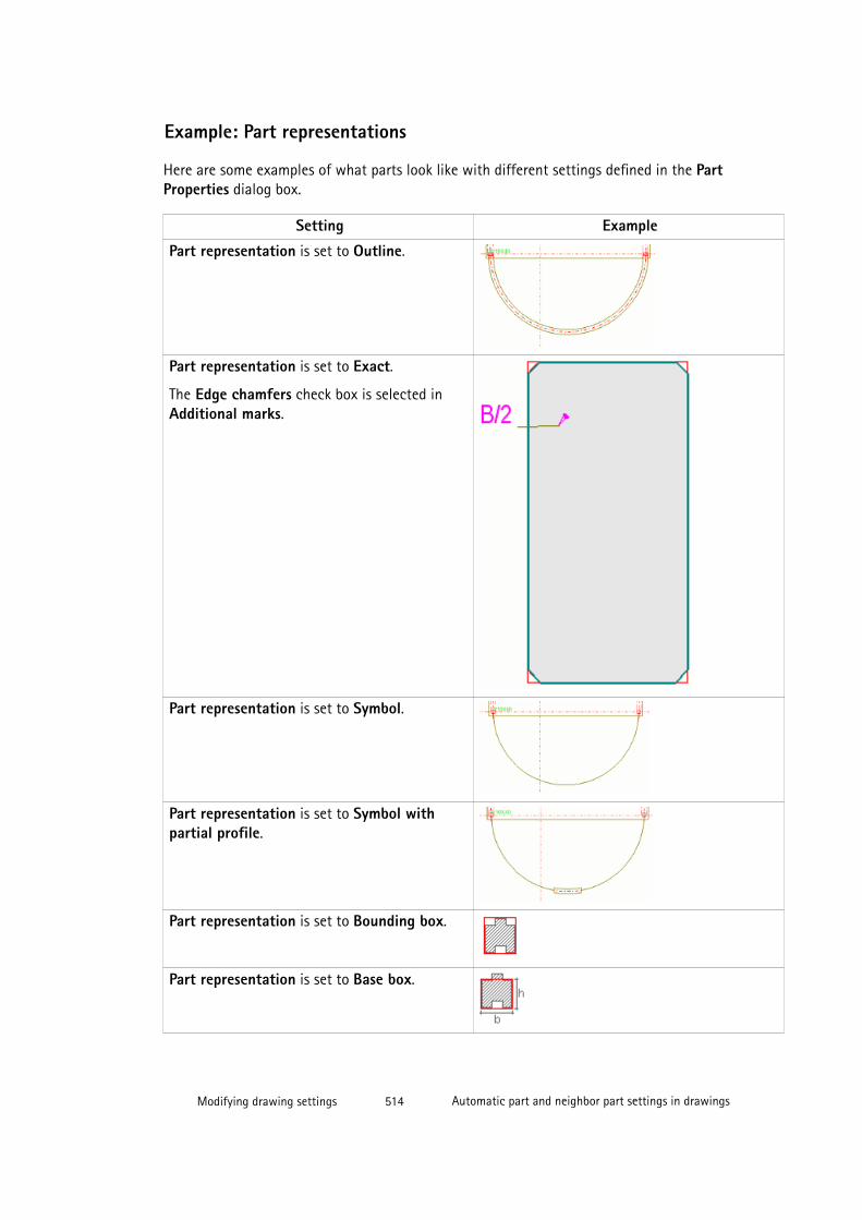
Example: Part representations
Here are some examples of what parts look like with different settings defined in the PartProperties dialog box.
Setting Example
Part representation is set to Outline.
Part representation is set to Exact.
The Edge chamfers check box is selected inAdditional marks.
Part representation is set to Symbol.
Part representation is set to Symbol withpartial profile.
Part representation is set to Bounding box.
Part representation is set to Base box.
Modifying drawing settings 514 Automatic part and neighbor part settings in drawings
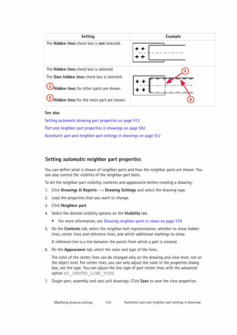
Setting Example
The Hidden lines check box is not selected.
The Hidden lines check box is selected.
The Own hidden lines check box is selected.
Hidden lines for other parts are shown
Hidden lines for the main part are shown.
See also
Setting automatic drawing part properties on page 513
Part and neighbor part properties in drawings on page 592
Automatic part and neighbor part settings in drawings on page 512
Setting automatic neighbor part properties
You can define what is shown of neighbor parts and how the neighbor parts are shown. Youcan also control the visibility of the neighbor part bolts.
To set the neighbor part visibility, contents and appearance before creating a drawing:
1. Click Drawings & Reports --> Drawing Settings and select the drawing type.
2. Load the properties that you want to change.
3. Click Neighbor part.
4. Select the desired visibility options on the Visibility tab.
• For more information, see Showing neighbor parts in views on page 379
5. On the Contents tab, select the neighbor bolt representation, whether to show hiddenlines, center lines and reference lines, and which additional markings to show.
A reference line is a line between the points from which a part is created.
6. On the Appearance tab, select the color and type of the lines.
The color of the center lines can be changed only on the drawing and view level, not onthe object level. For center lines, you can only adjust the color in the properties dialogbox, not the type. You can adjust the line type of part center lines with the advancedoption XS_CENTER_LINE_TYPE.
7. Single-part, assembly and cast unit drawings: Click Save to save the view properties.
Modifying drawing settings 515 Automatic part and neighbor part settings in drawings
8. Click OK.
9. Click Save to save the drawing properties, then click OK and create the drawing.
See also
Automatic part and neighbor part settings in drawings on page 512
Part and neighbor part properties in drawings on page 592
Example: Part representations on page 513
XS_CENTER_LINE_TYPE
XS_DRAWING_PART_REFERENCE_LINE_TYPE
XS_DRAWING_POINT_SCALE
Indicating part orientationPart orientation marks indicate the erection direction of assemblies and cast units. You canindicate the part orientation by using part marks, by including compass direction in marks,and showing orientation marks and connecting side marks.
See also
Mark location on page 486
Using part mark as an orientation mark in general arrangement drawings on page 516
Displaying compass direction in part marks on page 518
Displaying connecting side marks on page 520
Part and neighbor part properties in drawings on page 592
Automatic part and neighbor part settings in drawings on page 512
Using part mark as an orientation mark in general arrangement drawings
In general arrangement drawings, part marks appear at the same end as in assemblydrawings. Parts with the same assembly position are always marked at the same end.
To use the part marks as orientation marks in general arrangement drawings:
1. Select Drawings & Reports --> Drawings Settings --> Assembly Drawing .
2. Load the properties that you want to change.
3. In assembly drawing properties, click View creation --> Attributes and set theCoordinate system to oriented or model.
You must use oriented or model if you want the Viewing direction settings in Tools -->Options --> Options --> Orientation marks to have effect.
4. Click Save to save the properties and OK to close the dialog box.
Modifying drawing settings 516 Automatic part and neighbor part settings in drawings
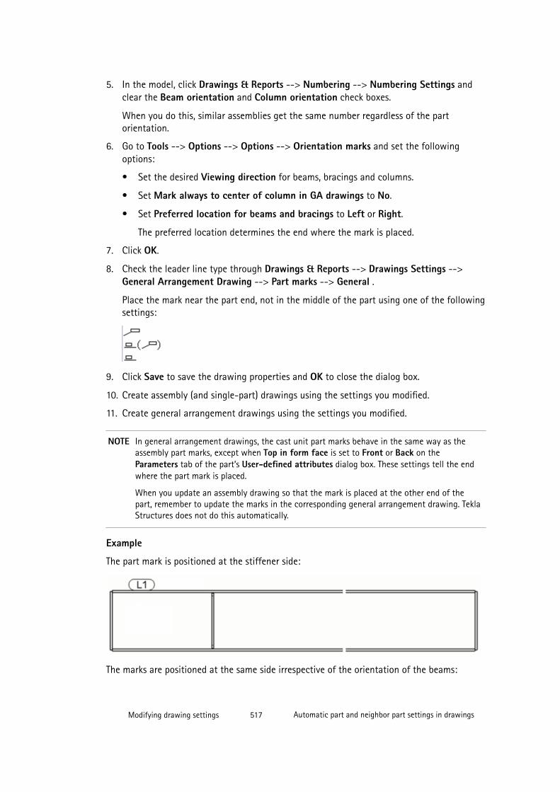
5. In the model, click Drawings & Reports --> Numbering --> Numbering Settings andclear the Beam orientation and Column orientation check boxes.
When you do this, similar assemblies get the same number regardless of the partorientation.
6. Go to Tools --> Options --> Options --> Orientation marks and set the followingoptions:
• Set the desired Viewing direction for beams, bracings and columns.
• Set Mark always to center of column in GA drawings to No.
• Set Preferred location for beams and bracings to Left or Right.
The preferred location determines the end where the mark is placed.
7. Click OK.
8. Check the leader line type through Drawings & Reports --> Drawings Settings -->General Arrangement Drawing --> Part marks --> General .
Place the mark near the part end, not in the middle of the part using one of the followingsettings:
9. Click Save to save the drawing properties and OK to close the dialog box.
10. Create assembly (and single-part) drawings using the settings you modified.
11. Create general arrangement drawings using the settings you modified.
NOTE In general arrangement drawings, the cast unit part marks behave in the same way as theassembly part marks, except when Top in form face is set to Front or Back on theParameters tab of the part’s User-defined attributes dialog box. These settings tell the endwhere the part mark is placed.
When you update an assembly drawing so that the mark is placed at the other end of thepart, remember to update the marks in the corresponding general arrangement drawing. TeklaStructures does not do this automatically.
Example
The part mark is positioned at the stiffener side:
The marks are positioned at the same side irrespective of the orientation of the beams:
Modifying drawing settings 517 Automatic part and neighbor part settings in drawings
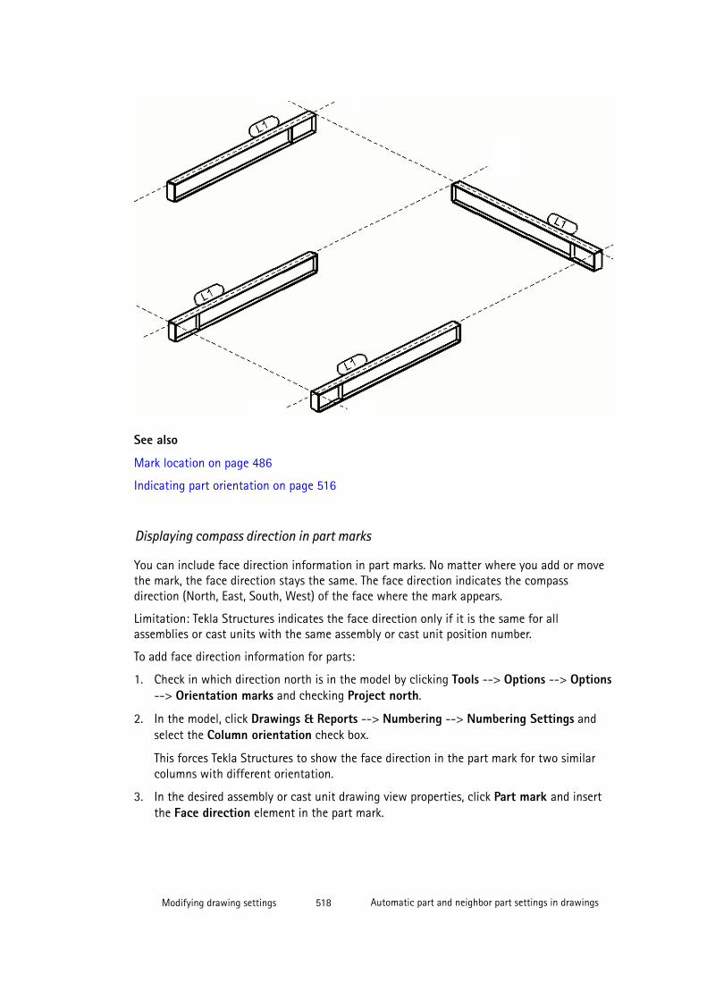
See also
Mark location on page 486
Indicating part orientation on page 516
Displaying compass direction in part marks
You can include face direction information in part marks. No matter where you add or movethe mark, the face direction stays the same. The face direction indicates the compassdirection (North, East, South, West) of the face where the mark appears.
Limitation: Tekla Structures indicates the face direction only if it is the same for allassemblies or cast units with the same assembly or cast unit position number.
To add face direction information for parts:
1. Check in which direction north is in the model by clicking Tools --> Options --> Options--> Orientation marks and checking Project north.
2. In the model, click Drawings & Reports --> Numbering --> Numbering Settings andselect the Column orientation check box.
This forces Tekla Structures to show the face direction in the part mark for two similarcolumns with different orientation.
3. In the desired assembly or cast unit drawing view properties, click Part mark and insertthe Face direction element in the part mark.
Modifying drawing settings 518 Automatic part and neighbor part settings in drawings
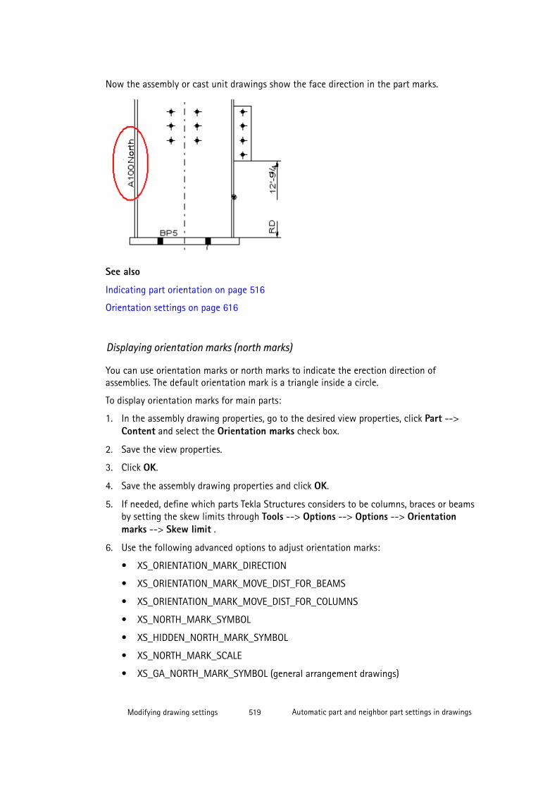
Now the assembly or cast unit drawings show the face direction in the part marks.
See also
Indicating part orientation on page 516
Orientation settings on page 616
Displaying orientation marks (north marks)
You can use orientation marks or north marks to indicate the erection direction ofassemblies. The default orientation mark is a triangle inside a circle.
To display orientation marks for main parts:
1. In the assembly drawing properties, go to the desired view properties, click Part -->Content and select the Orientation marks check box.
2. Save the view properties.
3. Click OK.
4. Save the assembly drawing properties and click OK.
5. If needed, define which parts Tekla Structures considers to be columns, braces or beamsby setting the skew limits through Tools --> Options --> Options --> Orientationmarks --> Skew limit .
6. Use the following advanced options to adjust orientation marks:
• XS_ORIENTATION_MARK_DIRECTION
• XS_ORIENTATION_MARK_MOVE_DIST_FOR_BEAMS
• XS_ORIENTATION_MARK_MOVE_DIST_FOR_COLUMNS
• XS_NORTH_MARK_SYMBOL
• XS_HIDDEN_NORTH_MARK_SYMBOL
• XS_NORTH_MARK_SCALE
• XS_GA_NORTH_MARK_SYMBOL (general arrangement drawings)
Modifying drawing settings 519 Automatic part and neighbor part settings in drawings

• XS_GA_HIDDEN_NORTH_MARK_SYMBOL (general arrangement drawings)
• XS_GA_NORTH_MARK_SCALE (general arrangement drawings)
7. Create the assembly drawing.
For different parts, Tekla Structures draws orientation marks in the following way:
• To the top flange of beams, at the end which points closest to the north or to thedirection defined in XS_ORIENTATION_MARK_DIRECTION (see part 1 and 2 in theillustration below)
• To the lower end of columns, on the flange which points closest to the north or to thedirection defined in XS_ORIENTATION_MARK_DIRECTION (see part 4 in theillustration below)
• To the flange of bracing, at the end which points closest to the north or to the directiondefined in XS_ORIENTATION_MARK_DIRECTION (see 3 A and B in the illustrationbelow)
TIP You can display orientation marks for single-part views included in assembly drawings by settingthe advanced option XS_SINGLE_ORIENTATION_MARK to TRUE.
See also
Indicating part orientation on page 516
Part and neighbor part properties in drawings on page 592
Displaying connecting side marks
You can use a symbol in assembly drawings to indicate the side of a part to which aconnecting part is attached.
To display connecting side marks:
1. Select Drawings & Reports --> Drawings Settings --> Assembly Drawing .
2. Load the properties that you want to change.
Modifying drawing settings 520 Automatic part and neighbor part settings in drawings
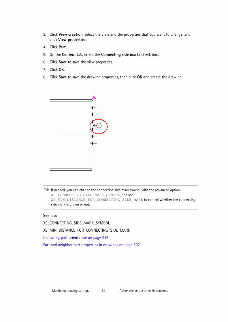
3. Click View creation, select the view and the properties that you want to change, andclick View properties.
4. Click Part.
5. On the Content tab, select the Connecting side marks check box.
6. Click Save to save the view properties.
7. Click OK.
8. Click Save to save the drawing properties, then click OK and create the drawing.
TIP If needed, you can change the connecting side mark symbol with the advanced option XS_CONNECTING_SIDE_MARK_SYMBOL, and use XS_MIN_DISTANCE_FOR_CONNECTING_SIDE_MARK to control whether the connectingside mark is drawn or not.
See also
XS_CONNECTING_SIDE_MARK_SYMBOL
XS_MIN_DISTANCE_FOR_CONNECTING_SIDE_MARK
Indicating part orientation on page 516
Part and neighbor part properties in drawings on page 592
Modifying drawing settings 521 Automatic bolt settings in drawings

7.17 Automatic bolt settings in drawingsBolts are connecting objects that fasten parts or assemblies or attach to them. There areseveral ways to display bolts in drawings.
See also
Setting automatic bolt properties in drawings on page 522
Creating user-defined bolt symbols on page 522
Example: Bolt representations on page 523
Bolt content and appearance properties in drawings on page 595
Part and neighbor part properties in drawings on page 592
Setting automatic bolt properties in drawings
You can define what is shown in bolts and how the bolts are shown.
To define the automatic bolt content and appearance settings before creating the drawing:
1. Click Drawings & Reports --> Drawing Settings and select the drawing type.
2. Load the properties that you want to change.
3. Single-part, assembly and cast unit drawings: Click View creation, select the view andthe properties that you want to change, and click View properties.
4. Click Bolts.
5. On the Content tab, select the bolt representation, bolt symbol content, and the visibilityof bolts in main parts.
For assembly and cast unit drawings, you can also set the visibility of bolts in secondaryparts and sub-assemblies.
6. On the Appearance tab, select the color of the bolts.
7. Single-part, assembly and cast unit drawings: Click Save to save the view properties.
8. Click OK.
9. Click Save to save the drawing properties, then click OK and create the drawing.
See also
Automatic bolt settings in drawings on page 521
Bolt content and appearance properties in drawings on page 595
Example: Bolt representations on page 523
Modifying drawing settings 522 Automatic bolt settings in drawings
Creating user-defined bolt symbolsYou can create your own bolt symbols and use them in drawings. You only need to createbolt symbols if you need different bolt symbols than the ones that you can find in TeklaStructures.
To create bolt symbols in the Symbol Editor and take them into use in your drawing:
1. Save the symbol file ud_bolts.sym in the symbol folder (usually the folder..\Tekla Structures\<version>\environments\common\symbols\).
2. Open Microsoft Notepad, or any text editor.
3. Create a text file consisting of lines in three columns:
• The first column contains the bolt assembly standard.
• The second contains the bolt diameter.
• The third column contains the name of the symbol file and the symbol number,separated with the @ character.
Example of file contents:
7990 24 ud_bolts@17990 25 ud_bolts@2Tekla Structures uses the user-defined symbol for bolts in drawings that have thestandard and diameter you define in this text file.
4. Save the file with the name bolt_symbol_table.txt.
5. Set the name of the file as a value for the advanced option XS_USER_DEFINED_BOLT_SYMBOL_TABLE in Tools --> Options --> AdvancedOptions --> Marking: Bolts as follows:
setXS_USER_DEFINED_BOLT_SYMBOL_TABLE=bolt_symbol_table.txtYou can also enter a full path to the bolt definition file. Without the path TeklaStructures searches for the file in the model, firm, project, and system directories.
6. To use your own bolt symbol, select Bolt --> Content --> Solid/Symbol --> User-defined symbol in the drawing view properties dialog box.
See also
Automatic bolt settings in drawings on page 521
Modifying drawing settings 523 Automatic bolt settings in drawings
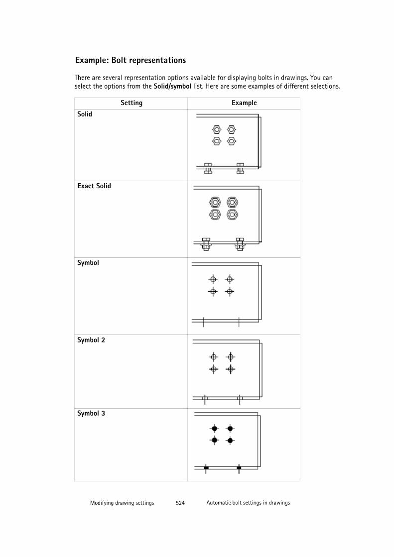
Example: Bolt representations
There are several representation options available for displaying bolts in drawings. You canselect the options from the Solid/symbol list. Here are some examples of different selections.
Setting ExampleSolid
Exact Solid
Symbol
Symbol 2
Symbol 3
Modifying drawing settings 524 Automatic bolt settings in drawings
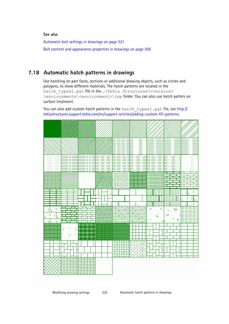
See also
Automatic bolt settings in drawings on page 521
Bolt content and appearance properties in drawings on page 595
7.18 Automatic hatch patterns in drawingsUse hatching on part faces, sections or additional drawing objects, such as circles andpolygons, to show different materials. The hatch patterns are located in thehatch_types1.pat file in the …\Tekla Structures\<version>\environments\<environment>\inp folder. You can also use hatch patters onsurface treatment.
You can also add custom hatch patterns in the hatch_types1.pat file, see http://teklastructures.support.tekla.com/en/support-articles/adding-custom-fill-patterns.
Modifying drawing settings 525 Automatic hatch patterns in drawings
See also
Adding automatic hatch patterns on drawing objects on page 526
Adding automatic surface treatment in drawings on page 530
Example: Insulation hatch patterns on page 528
Part and shape hatch pattern properties (.htc) on page 599
Surface treatment hatch pattern properties (surfacing.htc) on page 597
XS_HATCH_SPECIAL_COLOR_ACI
Adding automatic hatch patterns on drawing objects
You can add hatch patterns on parts, cross sections and shapes in a drawing.
There are some limitations in the hatch pattern background color usage:
• Background color does not work in conjunction with hardware hatches.
• The background color does not have any effect if there is an automatic hatch available.The background color can only be changed if the automatic hatch is not defined for thematerial type.
To add an automatic hatch pattern on a part before creating a drawing:
1. Click Drawings & Reports --> Drawing Settings and select the drawing type.
2. Load the properties that you want to change.
3. Single-part, assembly and cast unit drawings: Click View creation, select the view andthe properties that you want to change, and click View properties.
4. Click Part and go to the Fill tab.
5. Select the hatch pattern from the Type list.
To preview the patterns, click the ... button next to the Type list.
You can also select the hatch pattern by double-clicking it in the Hatch window. If youselect Automatic, Tekla Structures uses the hatch patterns defined in the hatch patternschema (hatch pattern properties) file (.htc). Each drawing type has its own schemafile.
6. Define a color for the pattern in the Color box.
7. Define a background color for the hatch in the Background box.
You can define the background color only after selecting a hatch pattern first.
8. In Scale, select whether to use automatic or custom scaling and rotation for hatches.
Modifying drawing settings 526 Automatic hatch patterns in drawings
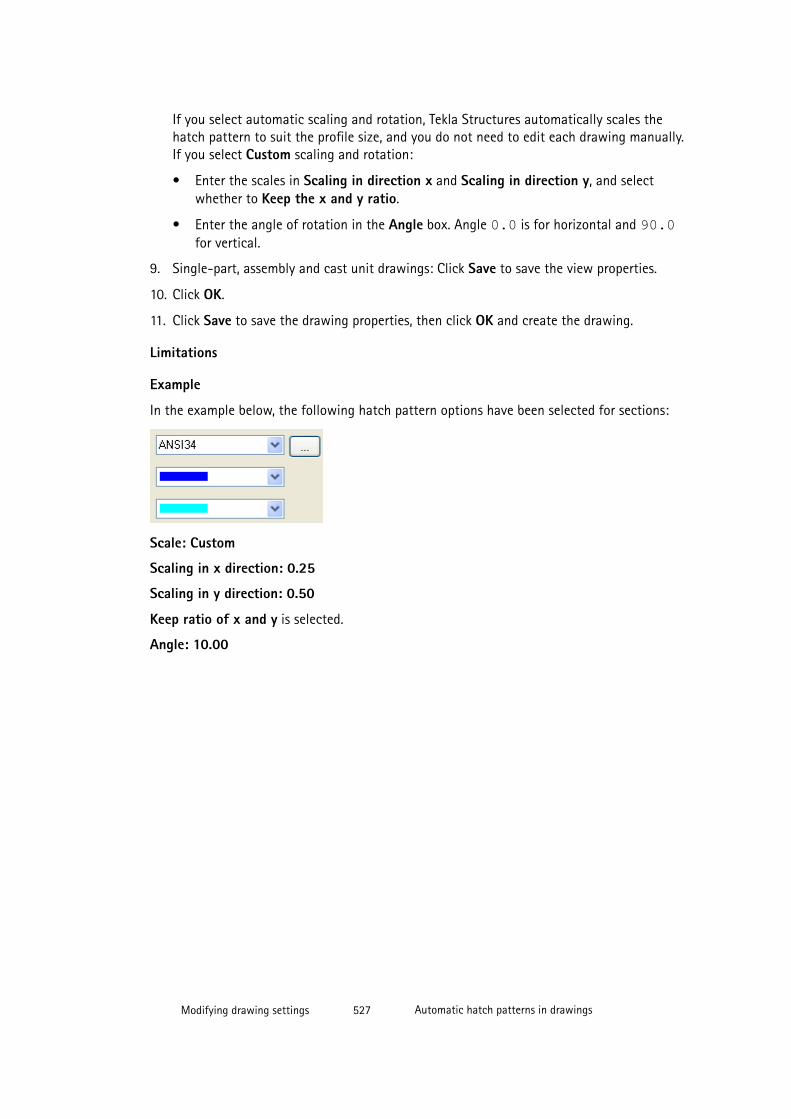
If you select automatic scaling and rotation, Tekla Structures automatically scales thehatch pattern to suit the profile size, and you do not need to edit each drawing manually.If you select Custom scaling and rotation:
• Enter the scales in Scaling in direction x and Scaling in direction y, and selectwhether to Keep the x and y ratio.
• Enter the angle of rotation in the Angle box. Angle 0.0 is for horizontal and 90.0for vertical.
9. Single-part, assembly and cast unit drawings: Click Save to save the view properties.
10. Click OK.
11. Click Save to save the drawing properties, then click OK and create the drawing.
Limitations
Example
In the example below, the following hatch pattern options have been selected for sections:
Scale: Custom
Scaling in x direction: 0.25
Scaling in y direction: 0.50
Keep ratio of x and y is selected.
Angle: 10.00
Modifying drawing settings 527 Automatic hatch patterns in drawings

See also
Automatic part and neighbor part settings in drawings on page 512
Part and neighbor part properties in drawings on page 592
Part and shape hatch pattern properties (.htc) on page 599
Automatic hatch patterns in drawings on page 525
XS_HATCH_SCALE_LIMIT
XS_HATCH_SPECIAL_COLOR_R
XS_HATCH_SEGMENT_BUFFER_SIZE
XS_HATCH_SPECIAL_COLOR_ACI
Example: Insulation hatch patterns
You can use the following fill types to represent insulation:
These hatch types can be scaled and rotated.
Modifying drawing settings 528 Automatic hatch patterns in drawings

Hatch name PatternHARD_INS1
SOFT_INS
SOFT_INS2
Previewing patterns
To preview the scaled and rotated patterns, click the ... button next to the Type box.
See also
Automatic hatch patterns in drawings on page 525
Modifying drawing settings 529 Automatic surface treatment in drawings
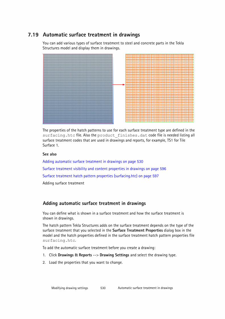
7.19 Automatic surface treatment in drawingsYou can add various types of surface treatment to steel and concrete parts in the TeklaStructures model and display them in drawings.
The properties of the hatch patterns to use for each surface treatment type are defined in thesurfacing.htc file. Also the product_finishes.dat code file is needed listing allsurface treatment codes that are used in drawings and reports, for example, TS1 for TileSurface 1.
See also
Adding automatic surface treatment in drawings on page 530
Surface treatment visibility and content properties in drawings on page 596
Surface treatment hatch pattern properties (surfacing.htc) on page 597
Adding surface treatment
Adding automatic surface treatment in drawings
You can define what is shown in a surface treatment and how the surface treatment isshown in drawings.
The hatch pattern Tekla Structures adds on the surface treatment depends on the type of thesurface treatment that you selected in the Surface Treatment Properties dialog box in themodel and the hatch properties defined in the surface treatment hatch pattern properties filesurfacing.htc.
To add the automatic surface treatment before you create a drawing:
1. Click Drawings & Reports --> Drawing Settings and select the drawing type.
2. Load the properties that you want to change.
Modifying drawing settings 530 Automatic surface treatment in drawings
3. Single-part, assembly and cast unit drawings: Click View creation, select the view andthe properties that you want to change, and click View properties.
4. Click Surface treatment.
5. On the Contents tab, select the surface treatment representation, and whether to showthe surface treatment pattern, hidden lines, and own hidden lines.
6. On the Appearance tab, select the color and type of visible and hidden lines.
7. Single-part, assembly and cast unit drawings: Click Save to save the view properties.
8. Click OK.
9. Click Save to save the drawing properties, then click OK and create the drawing.
See also
Automatic surface treatment in drawings on page 529
Surface treatment visibility and content properties in drawings on page 596
Surface treatment hatch pattern properties (surfacing.htc) on page 597
Automatic hatch patterns in drawings on page 525
7.20 Automatic weld settings in drawings
You can define automatic weld settings to be used in a drawing before you create a drawing.You can modify the settings after you have created the drawing.
See also
Weld concepts on page 211
Examples: Model welds in drawings on page 212
Welding properties on page 612
Setting automatic weld properties in drawings
To set the automatic weld properties before creating a drawing:
1. Click Drawings & Reports --> Drawing Settings and select the drawing type.
2. Load the properties that you want to change.
3. Single-part and assembly drawings: Click View creation, select the view and theproperties that you want to change, and click View properties.
4. Click Weld.
5. On the Content page, define the visibility settings.
Modifying drawing settings 531 Automatic weld settings in drawings
6. Enter a weld size to filter welds of that size out of the drawing.
This is useful when you only want to show non-typical welds in a drawing.
To set whether the weld size is an exact or minimum value, use the advanced option XS_WELD_FILTER_TYPE.
To filter out a standard weld type, use the advanced option XS_OMITTED_WELD_TYPE.
7. On the Appearance tab, modify the color and line as required.
8. Single-part and assembly drawings: Click Save to save the view properties.
9. Click OK.
10. Click Save to save the drawing properties, then click OK and create the drawing.
See also
Welding properties on page 612
Model weld mark visibility and appearance properties in drawings on page 580
7.21 Automatic reinforcement and mesh settings in drawingsThere are numerous ways of showing reinforcing bars and meshes in drawings. You candefine automatic reinforcement and mesh settings before you create the drawing, and adjustthe settings in an open drawing. In addition to modifying the properties available in theproperties dialog box, you can also modify the bending schedules, rounding of bardimensions, symbols in use, and reinforcement appearance in the rebar_config.inpsettings file.
See also
Setting automatic reinforcement and reinforcement mesh properties on page 532
Example: Hiding reinforcing bar lines in drawings on page 533
Example: Reinforcement representations on page 534
Reinforcement/Neighbor reinforcement and mesh properties in drawings on page 601
Reinforcement settings for drawings (rebar_config.inp) on page 603
Part and neighbor part properties in drawings on page 592
Setting automatic reinforcement and reinforcement mesh properties
You can define what is shown in reinforcing bars and meshes and how they are shown in castunit and general arrangement drawings. You can also do this for neighbor reinforcement.
To set automatic reinforcement and mesh properties before creating a drawing:
Modifying drawing settings 532 Automatic reinforcement and mesh settings in drawings
1. Click Drawings & Reports --> Drawing Settings and select the drawing type.
2. Load the properties that you want to change.
3. Single-part, assembly and cast unit drawings: Click View creation, select the view andthe properties that you want to change, and click View properties.
4. Click Reinforcement (or Neighbor reinforcement).
5. On the Bar content tab, set the bar representation, bar end symbols, and the visibility ofbars and lines.
6. On the Bar appearance tab, select the color and type of the visible lines and hidden lines.
7. On the Mesh content tab, set the mesh representation, mesh symbols, and the visibilityof meshes, wires, bars and lines.
8. On the Mesh appearance tab, select the color and type of the visible lines and hiddenlines.
9. Single-part, assembly and cast unit drawings: Click Save to save the view properties.
10. Click OK.
11. Click Save to save the drawing properties, then click OK and create the drawing.
TIP The representation of reinforcing bars that point away from the drawing is changeable. You cancustomize reinforcing bar bent symbols (cross, circle, filled circle) by editing the symbol filebent.sym, which in the default environment is located in the folder ..\ProgramData\Tekla Structures\<version>\\environments\common\symbols. Or, youcan create a new symbol file in the same folder, for example, my_new_symbols.sym, andtake it into use in the rebar_config.inp by entering the following string: BentSymbolFile=my_new_symbols.sym in the file.
See also
Automatic reinforcement and mesh settings in drawings on page 532
Reinforcement/Neighbor reinforcement and mesh properties in drawings on page 601
Reinforcement settings for drawings (rebar_config.inp) on page 603
Modifying drawing settings 533 Automatic reinforcement and mesh settings in drawings
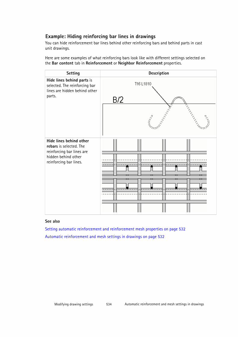
Example: Hiding reinforcing bar lines in drawingsYou can hide reinforcement bar lines behind other reinforcing bars and behind parts in castunit drawings.
Here are some examples of what reinforcing bars look like with different settings selected onthe Bar content tab in Reinforcement or Neighbor Reinforcement properties.
Setting Description
Hide lines behind parts isselected. The reinforcing barlines are hidden behind otherparts.
Hide lines behind otherrebars is selected. Thereinforcing bar lines arehidden behind otherreinforcing bar lines.
See also
Setting automatic reinforcement and reinforcement mesh properties on page 532
Automatic reinforcement and mesh settings in drawings on page 532
Modifying drawing settings 534 Automatic reinforcement and mesh settings in drawings
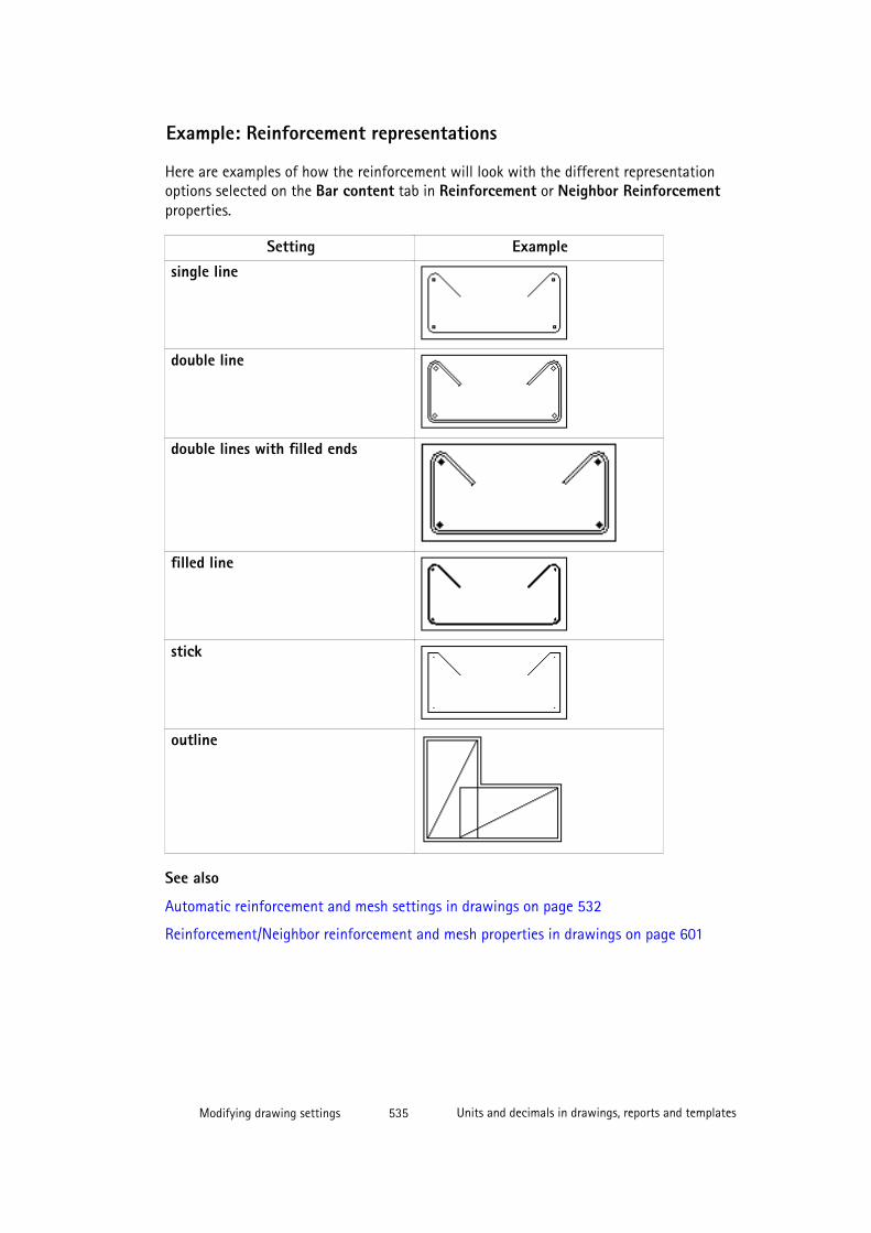
Example: Reinforcement representations
Here are examples of how the reinforcement will look with the different representationoptions selected on the Bar content tab in Reinforcement or Neighbor Reinforcementproperties.
Setting Examplesingle line
double line
double lines with filled ends
filled line
stick
outline
See also
Automatic reinforcement and mesh settings in drawings on page 532
Reinforcement/Neighbor reinforcement and mesh properties in drawings on page 601
Modifying drawing settings 535 Units and decimals in drawings, reports and templates

7.22 Units and decimals in drawings, reports and templatesUnit settings used in drawing objects, and reports and templates created in Template Editorare taken from different places. These settings include, for example, the used unit and thenumber of decimals.
In drawings, reports and templates, the units and decimals are defined in the following way:
• Unit settings for marks: Tekla Structures uses thecontentattributes_global.lst attributes file for setting the default unitsettings for various mark elements.
For more information about unit settings in marks, see Unit settings for marks on page495.
For more information about the contentattributes_global.lst file, seeTemplate attribute files.
• Unit settings for drawing objects: Default unit settings for drawing objects (other thanmarks) either come from the standard drawing properties files (standard.*) or arehardcoded in Tekla Structures.
• Unit settings for dimensions in dimension tags: Default unit settings for dimensiontags are defined in the Options dialog box on the Drawing dimensions page.
• Unit settings for reports/templates created with Template Editor: Unit settings forreports and templates created in Template Editor are defined in the Value FieldProperties dialog box or in format functions.
Modifying drawing settings 536 Units and decimals in drawings, reports and templates
7.23 User-defined attributes in drawings
Many Tekla Structures dialog boxes contain user-defined attributes for various objects. Thedefinitions of a user-defined attribute are unique, which means that a user-defined attributecannot have different definitions for different object types.
In drawings, the user-defined attributes can be used in templates, Drawing List, and marks,for example. The user-defined attributes defined in the drawing are displayed when you clickUser-defined attributes in the drawing properties dialog box. You can show up to 20 user-defined attributes in the Drawing List. To check the ones that you have, click User-definedattributes in a drawing properties dialog box.
To define new user-defined attributes, create your own objects.inp file in the company,project or firm folder. After adding your own user-defined attributes, you need to use theDiagnose & Change Attribute Definitions tool to update the definitions in the model. Theobject.inp files are merged so that if there are user-defined attributes in any of the files,they are displayed in the user interface. Tekla Structures merges the files in a way thateliminates duplicate attributes. If Tekla Structures encounters the same attribute name indifferent objects.inp files, the attribute from the first read objects.inp file will beused.
Tekla Structures reads the objects.inp files from the following folders in the followingorder:
1. model folder
2. company folder
3. project folder
4. firm folder
5. system folder
6. inp folder
In order to show the new user-defined attribute in Template Editor, you need to add it in acustomized contentattributes_userdefine.lst file and include the name ofthe customized file in the contentattributes.lst file.
Make a copy of these modified files as the Tekla Structures installation always overwritesthese files.
See also
Modifying automatic user-defined drawing attributes on page 538
Creating new user-defined drawing attributes on page 539
Modifying drawing settings 537 User-defined attributes in drawings
Adding user-defined attributes and template attributes in marks on page 499
What is displayed in the Drawing List on page 106
Switches for customizing print file names on page 306
Objects.inp properties
Modifying automatic user-defined drawing attributes
To modify user-defined drawing attributes before creating a drawing:
1. Click Drawings & Reports --> Drawing Settings and select the drawing type.
2. Load the properties that you want to change.
3. Click User-defined attributes.
4. On the Workflow tab, enter project-specific information to be displayed in drawings andin the Drawing List.
5. On the Parameters tab, enter a user-defined Comment for drawings, projects, assemblies,parts, and so on.
6. Use the User field 1 to User field 8 on the Parameters tab to enter drawing-specificinformation.
7. On the Title tab, select if you want to use project-specific or drawing-specificinformation in the title block of the drawing.
When you click Use project settings, you cannot enter any information in the title blockfields.
8. If you selected Use drawing settings, the title block fields become available, and you canenter the necessary data in the fields.
9. Click Save to save the drawing properties, then click OK and create the drawing.
TIP • You can control whether the modifications in user-defined attributes affect allselected drawings in the Drawing List at the same time, even if the drawings areof different types by using the advanced option XS_DRAWING_UDAS_MODIFY_ALL_DRAWING_TYPES.
See also
Customizing user-defined attributes
XS_DRAWING_UDAS_MODIFY_ALL_DRAWING_TYPES
Location of certain files in hidden folders
User-defined attributes in drawings on page 537
Creating new user-defined drawing attributes on page 539
Modifying drawing settings 538 User-defined attributes in drawings
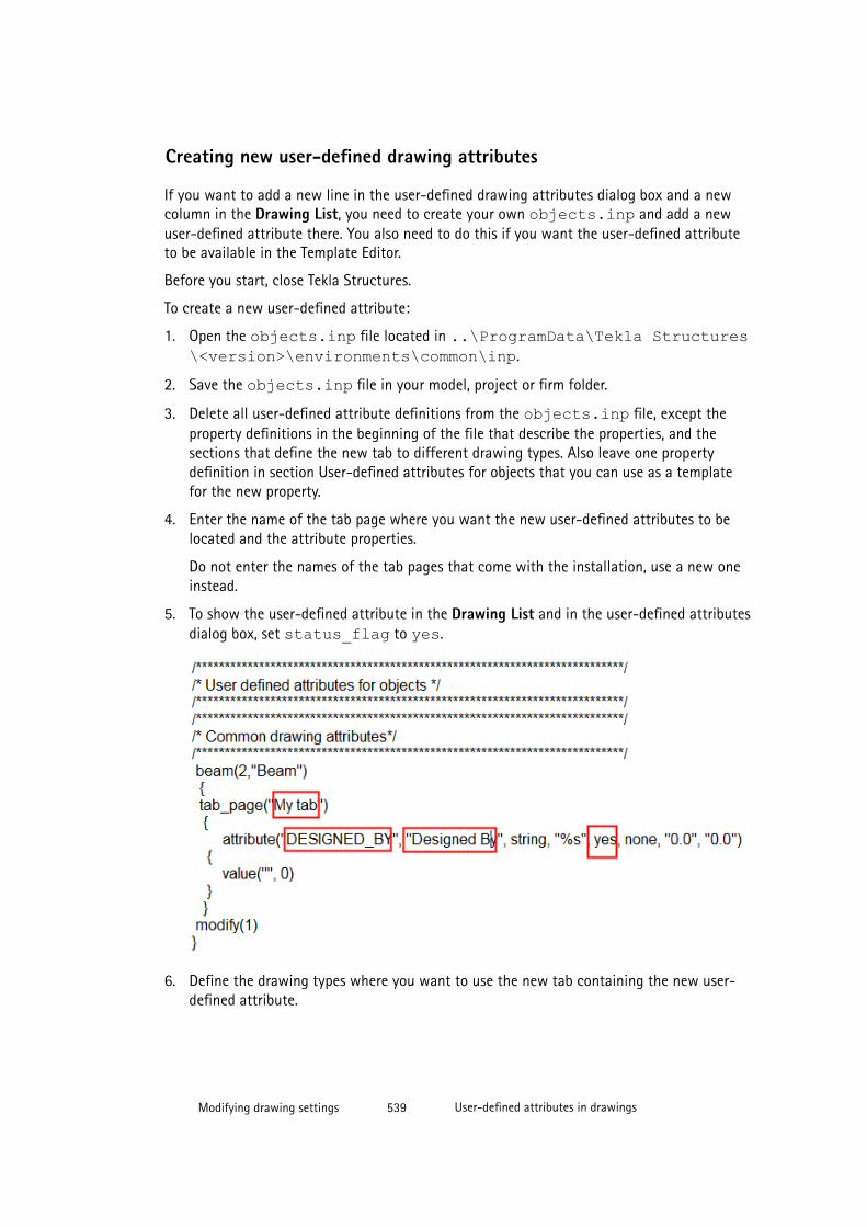
Creating new user-defined drawing attributes
If you want to add a new line in the user-defined drawing attributes dialog box and a newcolumn in the Drawing List, you need to create your own objects.inp and add a newuser-defined attribute there. You also need to do this if you want the user-defined attributeto be available in the Template Editor.
Before you start, close Tekla Structures.
To create a new user-defined attribute:
1. Open the objects.inp file located in ..\ProgramData\Tekla Structures\<version>\environments\common\inp.
2. Save the objects.inp file in your model, project or firm folder.
3. Delete all user-defined attribute definitions from the objects.inp file, except theproperty definitions in the beginning of the file that describe the properties, and thesections that define the new tab to different drawing types. Also leave one propertydefinition in section User-defined attributes for objects that you can use as a templatefor the new property.
4. Enter the name of the tab page where you want the new user-defined attributes to belocated and the attribute properties.
Do not enter the names of the tab pages that come with the installation, use a new oneinstead.
5. To show the user-defined attribute in the Drawing List and in the user-defined attributesdialog box, set status_flag to yes.
6. Define the drawing types where you want to use the new tab containing the new user-defined attribute.
Modifying drawing settings 539 User-defined attributes in drawings
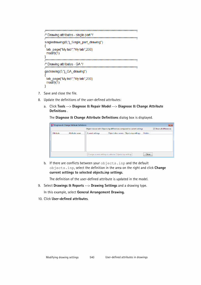
7. Save and close the file.
8. Update the definitions of the user-defined attributes:
a. Click Tools --> Diagnose & Repair Model --> Diagnose & Change AttributeDefinitions .
The Diagnose & Change Attribute Definitions dialog box is displayed.
b. If there are conflicts between your objects.inp and the defaultobjects.inp, select the definition in the area on the right and click Changecurrent settings to selected objects.inp settings.
The definition of the user-defined attribute is updated in the model.
9. Select Drawings & Reports --> Drawing Settings and a drawing type.
In this example, select General Arrangement Drawing.
10. Click User-defined attributes.
Modifying drawing settings 540 User-defined attributes in drawings
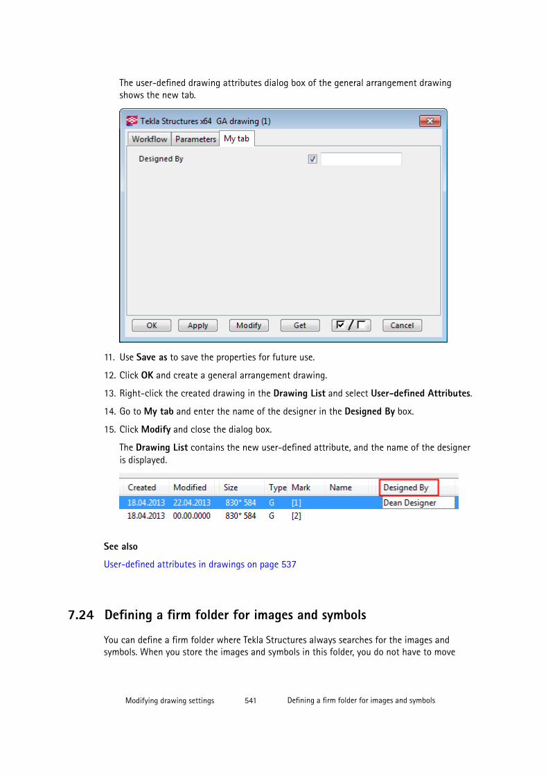
The user-defined drawing attributes dialog box of the general arrangement drawingshows the new tab.
11. Use Save as to save the properties for future use.
12. Click OK and create a general arrangement drawing.
13. Right-click the created drawing in the Drawing List and select User-defined Attributes.
14. Go to My tab and enter the name of the designer in the Designed By box.
15. Click Modify and close the dialog box.
The Drawing List contains the new user-defined attribute, and the name of the designeris displayed.
See also
User-defined attributes in drawings on page 537
7.24 Defining a firm folder for images and symbols
You can define a firm folder where Tekla Structures always searches for the images andsymbols. When you store the images and symbols in this folder, you do not have to move
Modifying drawing settings 541 Defining a firm folder for images and symbols
them from folder to folder when you install a new version of Tekla Structures. Installing anew version does not replace the files in the firm folder.
Define the firm folder in the options.ini file under the model folder or user.iniusing the advanced option XS_FIRM.
To define the firm folder for images and symbols in the options.ini file:
1. Modify the options.ini file to include the advanced option DXK_SYMBOLPATHthat points to the firm folder.
The advanced option DXK_SYMBOLPATH may contain multiple paths separated bysemicolons.
Since Tekla Structures version 19.0, the folder path definitions like %DATADIR% or %XS_FIRM% in DXK_SYMBOLPATH have not converted the paths correctly when usedin options.ini located in the firm folder. However, these definitions work correctly ifused in user.ini. Currently you need to write the absolute paths for DXK_SYMBOLPATH in options.ini in the firm folder, like in the example below:
DXK_SYMBOLPATH=C:\TeklaStructures\21.0\environments\common\symbols\;C:\firm\Symbols\;
2. In Template Editor, click Options --> Preferences --> File Locations and enter the pathto the firm folder also for Symbols, pictures.
See also
Symbols in drawings on page 243
DXK_SYMBOLPATH
7.25 Defining customized line types
You can define your own line types, and use them wherever line type settings are available.The customized line types are handled the same way as other line types. The customized linetypes are defined in the TeklaStuctures.lin file in ..\ProgramData\TeklaStructures\<version>\environments\common\inp. By default, the mostwidely used line types are available in the file.
To define your own line types in the TeklaStuctures.lin file:
1. Start every line with the letter A to indicate the beginning of the line type pattern.
You can use three different objects: dashes, dots and spaces to form a line.
2. Define the length of a dash (-) using positive numbers.
3. Define the length of a a space ( ) using negative numbers.
4. Define dots (.) using the number zero (0).
The patterns must begin with a dash. They typically end with a space, although the spacein the end is not required.
Modifying drawing settings 542 Defining customized line types
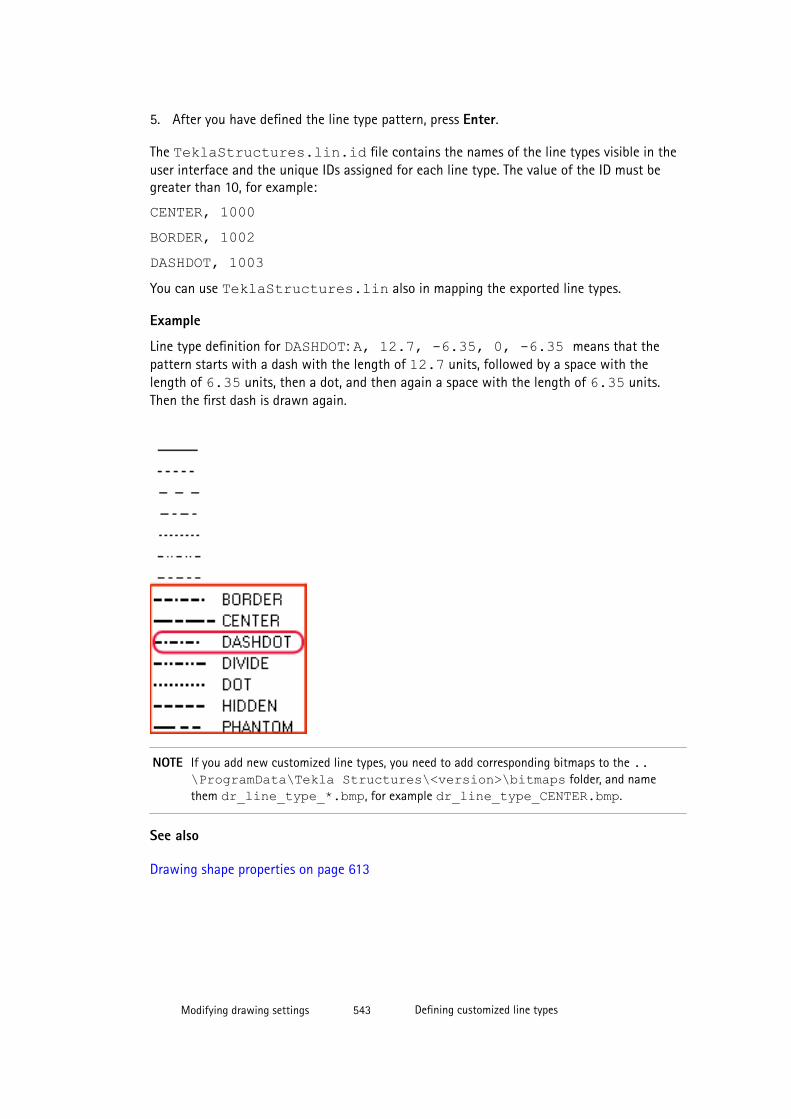
5. After you have defined the line type pattern, press Enter.
The TeklaStructures.lin.id file contains the names of the line types visible in theuser interface and the unique IDs assigned for each line type. The value of the ID must begreater than 10, for example:
CENTER, 1000BORDER, 1002DASHDOT, 1003You can use TeklaStructures.lin also in mapping the exported line types.
Example
Line type definition for DASHDOT: A, 12.7, -6.35, 0, -6.35 means that thepattern starts with a dash with the length of 12.7 units, followed by a space with thelength of 6.35 units, then a dot, and then again a space with the length of 6.35 units.Then the first dash is drawn again.
NOTE If you add new customized line types, you need to add corresponding bitmaps to the ..\ProgramData\Tekla Structures\<version>\bitmaps folder, and namethem dr_line_type_*.bmp, for example dr_line_type_CENTER.bmp.
See also
Drawing shape properties on page 613
Modifying drawing settings 543 Defining customized line types

8 Drawing settings
There are a lot of settings in Tekla Structures that you mainly control in the properties dialogboxes. There are also some additional settings files that you need.
Click the links below to find out more:
• General arrangement drawing properties on page 544
• Single-part, assembly and cast unit drawing properties on page 548
• Layout properties on page 549
• View properties in drawings on page 551
• Section view properties on page 555
• Dimension and dimensioning properties on page 556
• Mark properties on page 573
• Mark elements on page 583
• Part and neighbor part properties in drawings on page 592
• Bolt content and appearance properties in drawings on page 595
• Surface treatment visibility and content properties in drawings on page 596
• Surface treatment hatch pattern properties (surfacing.htc) on page 597
• Part and shape hatch pattern properties (.htc) on page 599
• Reinforcement/Neighbor reinforcement and mesh properties in drawings on page 601
• Reinforcement settings for drawings (rebar_config.inp) on page 603
• Placement properties for annotation objects on page 612
• Welding properties on page 612
• Drawing shape properties on page 613
• Drawing grid properties on page 615
• Orientation settings on page 616
Drawing settings 544 General arrangement drawing properties
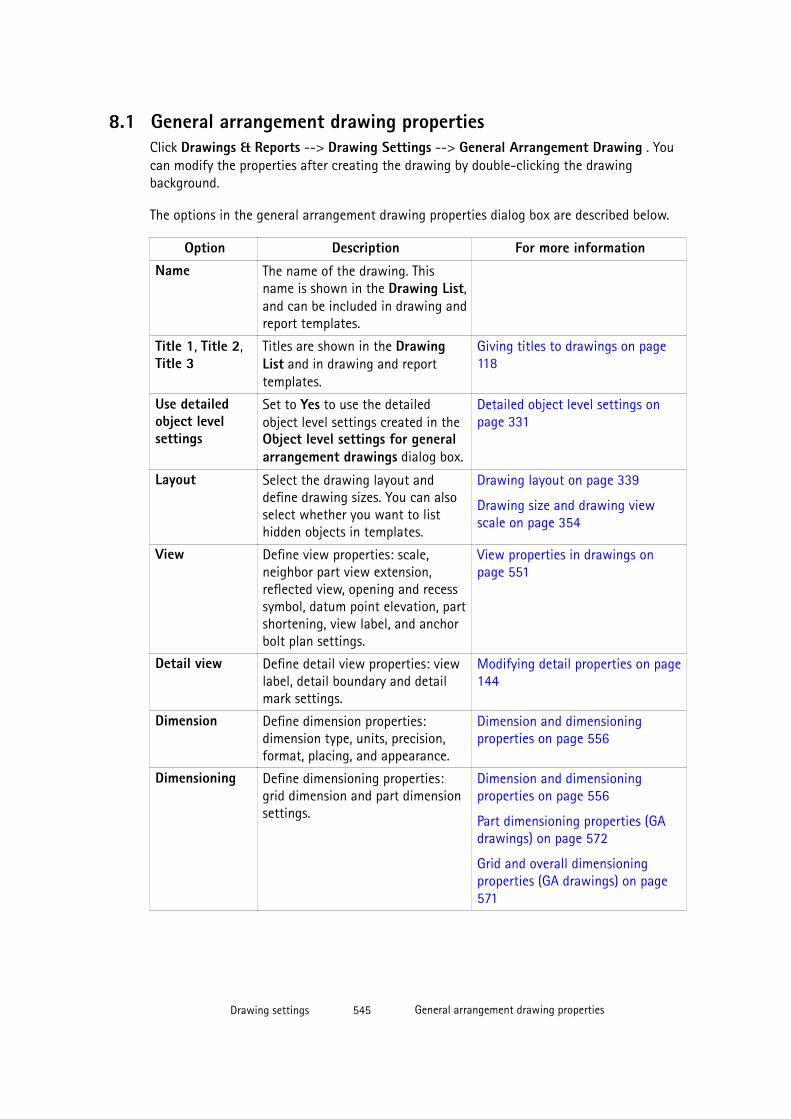
8.1 General arrangement drawing propertiesClick Drawings & Reports --> Drawing Settings --> General Arrangement Drawing . Youcan modify the properties after creating the drawing by double-clicking the drawingbackground.
The options in the general arrangement drawing properties dialog box are described below.
Option Description For more informationName The name of the drawing. This
name is shown in the Drawing List,and can be included in drawing andreport templates.
Title 1, Title 2,Title 3
Titles are shown in the DrawingList and in drawing and reporttemplates.
Giving titles to drawings on page118
Use detailedobject levelsettings
Set to Yes to use the detailedobject level settings created in theObject level settings for generalarrangement drawings dialog box.
Detailed object level settings onpage 331
Layout Select the drawing layout anddefine drawing sizes. You can alsoselect whether you want to listhidden objects in templates.
Drawing layout on page 339
Drawing size and drawing viewscale on page 354
View Define view properties: scale,neighbor part view extension,reflected view, opening and recesssymbol, datum point elevation, partshortening, view label, and anchorbolt plan settings.
View properties in drawings onpage 551
Detail view Define detail view properties: viewlabel, detail boundary and detailmark settings.
Modifying detail properties on page144
Dimension Define dimension properties:dimension type, units, precision,format, placing, and appearance.
Dimension and dimensioningproperties on page 556
Dimensioning Define dimensioning properties:grid dimension and part dimensionsettings.
Dimension and dimensioningproperties on page 556
Part dimensioning properties (GAdrawings) on page 572
Grid and overall dimensioningproperties (GA drawings) on page571
Drawing settings 545 General arrangement drawing properties

Option Description For more informationPart mark
Bolt mark
Neighbor partmark
Surfacetreatment mark
Weld mark
Reinforcementmarks
Neighborreinforcementmarks
Connectionmark
Pour objectmark
Define mark properties: includedelements and element settings, andmark visibility, mark frame, markleader line and placing settings.
Mark properties on page 573
Part and neighbor part properties indrawings on page 592
Drawing weld mark properties onpage 578
Mark appearance and mergingproperties on page 573
Model weld mark visibility andappearance properties in drawingson page 580
Mark elements on page 583
Pours in drawings on page 236
Part Define part properties: partrepresentation, hidden line, centerline and reference line visibility,additional mark visibility, partappearance, and fill settings.
Part and neighbor part properties indrawings on page 592
Bolt Define bolt properties: boltrepresentation, bolt symbolcontent, bolt visibility, and boltappearance settings.
Bolt content and appearanceproperties in drawings on page595
Neighbor part Define neighbor part properties:visibility, part representation,hidden line, center line andreference line visibility, additionalmark visibility, and part appearancesettings. You can also define boltrepresentation and bolt symbolcontent settings for neighbor parts.
Part and neighbor part properties indrawings on page 592
Surfacetreatment
Define surface treatmentproperties: surface treatmentvisibility, pattern visibility, hiddenlines visibility and surfacetreatment representation settings.
Surface treatment visibility andcontent properties in drawings onpage 596
Weld Define welding properties: weldvisibility, weld size limit and weldappearance settings.
Welding properties on page 612
Drawing settings 546 General arrangement drawing properties
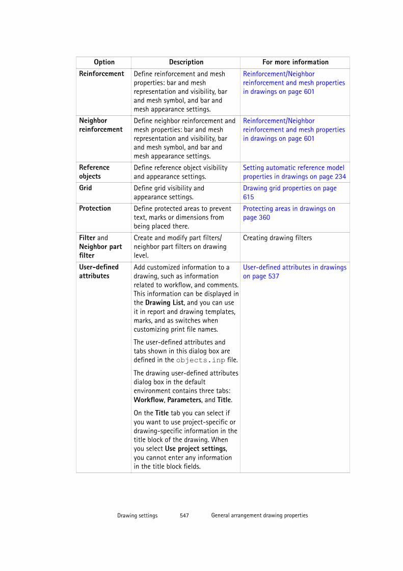
Option Description For more informationReinforcement Define reinforcement and mesh
properties: bar and meshrepresentation and visibility, barand mesh symbol, and bar andmesh appearance settings.
Reinforcement/Neighborreinforcement and mesh propertiesin drawings on page 601
Neighborreinforcement
Define neighbor reinforcement andmesh properties: bar and meshrepresentation and visibility, barand mesh symbol, and bar andmesh appearance settings.
Reinforcement/Neighborreinforcement and mesh propertiesin drawings on page 601
Referenceobjects
Define reference object visibilityand appearance settings.
Setting automatic reference modelproperties in drawings on page 234
Grid Define grid visibility andappearance settings.
Drawing grid properties on page615
Protection Define protected areas to preventtext, marks or dimensions frombeing placed there.
Protecting areas in drawings onpage 360
Filter andNeighbor partfilter
Create and modify part filters/neighbor part filters on drawinglevel.
Creating drawing filters
User-definedattributes
Add customized information to adrawing, such as informationrelated to workflow, and comments.This information can be displayed inthe Drawing List, and you can useit in report and drawing templates,marks, and as switches whencustomizing print file names.
The user-defined attributes andtabs shown in this dialog box aredefined in the objects.inp file.
The drawing user-defined attributesdialog box in the defaultenvironment contains three tabs:Workflow, Parameters, and Title.
On the Title tab you can select ifyou want to use project-specific ordrawing-specific information in thetitle block of the drawing. Whenyou select Use project settings,you cannot enter any informationin the title block fields.
User-defined attributes in drawingson page 537
Drawing settings 547 General arrangement drawing properties
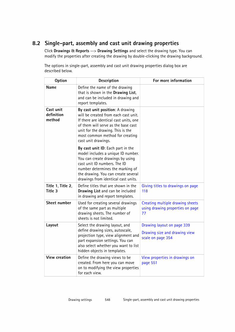
8.2 Single-part, assembly and cast unit drawing propertiesClick Drawings & Reports --> Drawing Settings and select the drawing type. You canmodify the properties after creating the drawing by double-clicking the drawing background.
The options in single-part, assembly and cast unit drawing properties dialog box aredescribed below.
Option Description For more informationName Define the name of the drawing
that is shown in the Drawing List,and can be included in drawing andreport templates.
Cast unitdefinitionmethod
By cast unit position: A drawingwill be created from each cast unit.If there are identical cast units, oneof them will serve as the base castunit for the drawing. This is themost common method for creatingcast unit drawings.
By cast unit ID: Each part in themodel includes a unique ID number.You can create drawings by usingcast unit ID numbers. The IDnumber determines the marking ofthe drawing. You can create severaldrawings from identical cast units.
Title 1, Title 2,Title 3
Define titles that are shown in theDrawing List and can be includedin drawing and report templates.
Giving titles to drawings on page118
Sheet number Used for creating several drawingsof the same part as multipledrawing sheets. The number ofsheets is not limited.
Creating multiple drawing sheetsusing drawing properties on page77
Layout Select the drawing layout, anddefine drawing sizes, autoscale,projection type, view alignment andpart expansion settings. You canalso select whether you want to listhidden objects in templates.
Drawing layout on page 339
Drawing size and drawing viewscale on page 354
View creation Define the drawing views to becreated. From here you can moveon to modifying the view propertiesfor each view.
View properties in drawings onpage 551
Drawing settings 548 Single-part, assembly and cast unit drawing properties
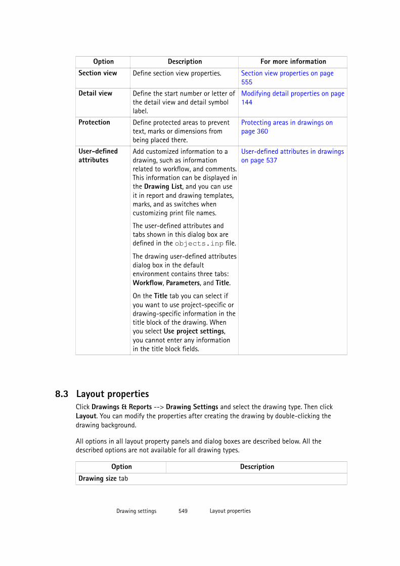
Option Description For more informationSection view Define section view properties. Section view properties on page
555
Detail view Define the start number or letter ofthe detail view and detail symbollabel.
Modifying detail properties on page144
Protection Define protected areas to preventtext, marks or dimensions frombeing placed there.
Protecting areas in drawings onpage 360
User-definedattributes
Add customized information to adrawing, such as informationrelated to workflow, and comments.This information can be displayed inthe Drawing List, and you can useit in report and drawing templates,marks, and as switches whencustomizing print file names.
The user-defined attributes andtabs shown in this dialog box aredefined in the objects.inp file.
The drawing user-defined attributesdialog box in the defaultenvironment contains three tabs:Workflow, Parameters, and Title.
On the Title tab you can select ifyou want to use project-specific ordrawing-specific information in thetitle block of the drawing. Whenyou select Use project settings,you cannot enter any informationin the title block fields.
User-defined attributes in drawingson page 537
8.3 Layout propertiesClick Drawings & Reports --> Drawing Settings and select the drawing type. Then clickLayout. You can modify the properties after creating the drawing by double-clicking thedrawing background.
All options in all layout property panels and dialog boxes are described below. All thedescribed options are not available for all drawing types.
Option Description
Drawing size tab
Drawing settings 549 Layout properties
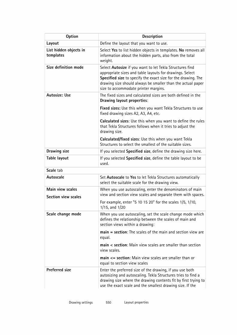
Option DescriptionLayout Define the layout that you want to use.
List hidden objects intemplates
Select Yes to list hidden objects in templates. No removes allinformation about the hidden parts, also from the totalweight.
Size definition mode Select Autosize if you want to let Tekla Structures findappropriate sizes and table layouts for drawings. SelectSpecified size to specify the exact size for the drawing. Thedrawing size should always be smaller than the actual papersize to accommodate printer margins.
Autosize: Use The fixed sizes and calculated sizes are both defined in theDrawing layout properties:
Fixed sizes: Use this when you want Tekla Structures to usefixed drawing sizes A2, A3, A4, etc.
Calculated sizes: Use this when you want to define the rulesthat Tekla Structures follows when it tries to adjust thedrawing size.
Calculated/fixed sizes: Use this when you want TeklaStructures to select the smallest of the suitable sizes.
Drawing size If you selected Specified size, define the drawing size here.
Table layout If you selected Specified size, define the table layout to beused.
Scale tab
Autoscale Set Autoscale to Yes to let Tekla Structures automaticallyselect the suitable scale for the drawing view.
Main view scales
Section view scales
When you use autoscaling, enter the denominators of mainview and section view scales and separate them with spaces.
For example, enter "5 10 15 20" for the scales 1/5, 1/10,1/15, and 1/20
Scale change mode When you use autoscaling, set the scale change mode whichdefines the relationship between the scales of main andsection views within a drawing:
main = section: The scales of the main and section view areequal.
main < section: Main view scales are smaller than sectionview scales.
main <= section: Main view scales are smaller than orequal to section view scales
Preferred size Enter the preferred size of the drawing, if you use bothautosizing and autoscaling. Tekla Structures tries to find adrawing size where the drawing contents fit by first trying touse the exact scale and the smallest drawing size. If the
Drawing settings 550 Layout properties
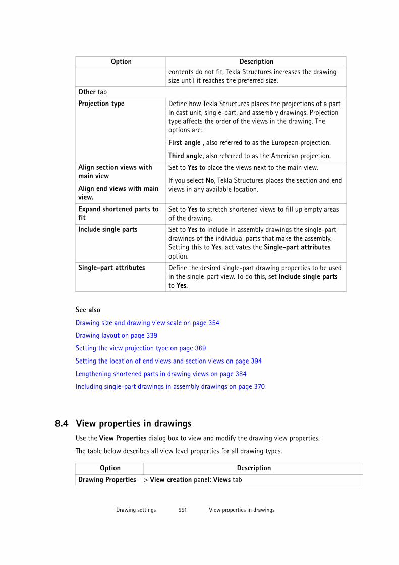
Option Descriptioncontents do not fit, Tekla Structures increases the drawingsize until it reaches the preferred size.
Other tab
Projection type Define how Tekla Structures places the projections of a partin cast unit, single-part, and assembly drawings. Projectiontype affects the order of the views in the drawing. Theoptions are:
First angle , also referred to as the European projection.
Third angle, also referred to as the American projection.
Align section views withmain view
Align end views with mainview.
Set to Yes to place the views next to the main view.
If you select No, Tekla Structures places the section and endviews in any available location.
Expand shortened parts tofit
Set to Yes to stretch shortened views to fill up empty areasof the drawing.
Include single parts Set to Yes to include in assembly drawings the single-partdrawings of the individual parts that make the assembly.Setting this to Yes, activates the Single-part attributesoption.
Single-part attributes Define the desired single-part drawing properties to be usedin the single-part view. To do this, set Include single partsto Yes.
See also
Drawing size and drawing view scale on page 354
Drawing layout on page 339
Setting the view projection type on page 369
Setting the location of end views and section views on page 394
Lengthening shortened parts in drawing views on page 384
Including single-part drawings in assembly drawings on page 370
8.4 View properties in drawingsUse the View Properties dialog box to view and modify the drawing view properties.
The table below describes all view level properties for all drawing types.
Option Description
Drawing Properties --> View creation panel: Views tab
Drawing settings 551 View properties in drawings
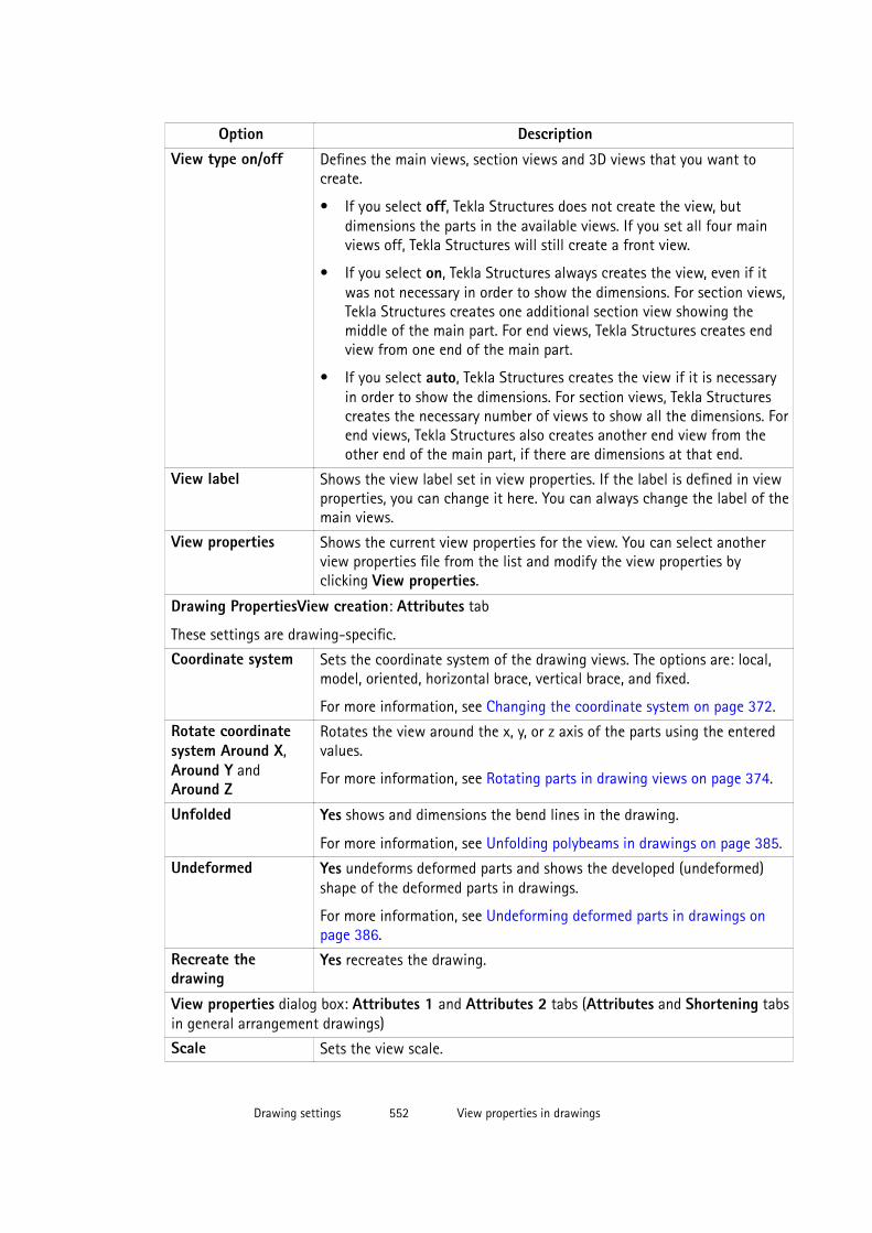
Option DescriptionView type on/off Defines the main views, section views and 3D views that you want to
create.
• If you select off, Tekla Structures does not create the view, butdimensions the parts in the available views. If you set all four mainviews off, Tekla Structures will still create a front view.
• If you select on, Tekla Structures always creates the view, even if itwas not necessary in order to show the dimensions. For section views,Tekla Structures creates one additional section view showing themiddle of the main part. For end views, Tekla Structures creates endview from one end of the main part.
• If you select auto, Tekla Structures creates the view if it is necessaryin order to show the dimensions. For section views, Tekla Structurescreates the necessary number of views to show all the dimensions. Forend views, Tekla Structures also creates another end view from theother end of the main part, if there are dimensions at that end.
View label Shows the view label set in view properties. If the label is defined in viewproperties, you can change it here. You can always change the label of themain views.
View properties Shows the current view properties for the view. You can select anotherview properties file from the list and modify the view properties byclicking View properties.
Drawing PropertiesView creation: Attributes tab
These settings are drawing-specific.
Coordinate system Sets the coordinate system of the drawing views. The options are: local,model, oriented, horizontal brace, vertical brace, and fixed.
For more information, see Changing the coordinate system on page 372.
Rotate coordinatesystem Around X,Around Y andAround Z
Rotates the view around the x, y, or z axis of the parts using the enteredvalues.
For more information, see Rotating parts in drawing views on page 374.
Unfolded Yes shows and dimensions the bend lines in the drawing.
For more information, see Unfolding polybeams in drawings on page 385.
Undeformed Yes undeforms deformed parts and shows the developed (undeformed)shape of the deformed parts in drawings.
For more information, see Undeforming deformed parts in drawings onpage 386.
Recreate thedrawing
Yes recreates the drawing.
View properties dialog box: Attributes 1 and Attributes 2 tabs (Attributes and Shortening tabsin general arrangement drawings)
Scale Sets the view scale.
Drawing settings 552 View properties in drawings
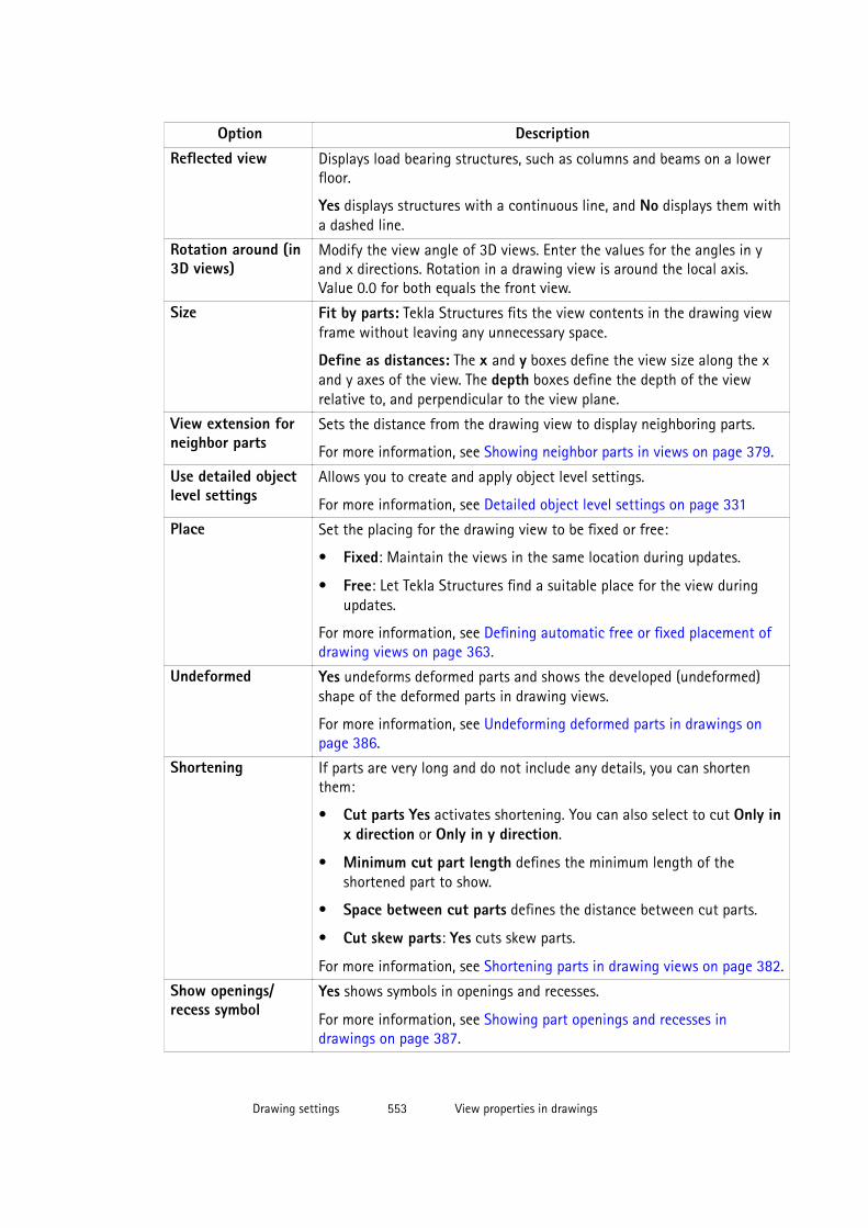
Option DescriptionReflected view Displays load bearing structures, such as columns and beams on a lower
floor.
Yes displays structures with a continuous line, and No displays them witha dashed line.
Rotation around (in3D views)
Modify the view angle of 3D views. Enter the values for the angles in yand x directions. Rotation in a drawing view is around the local axis.Value 0.0 for both equals the front view.
Size Fit by parts: Tekla Structures fits the view contents in the drawing viewframe without leaving any unnecessary space.
Define as distances: The x and y boxes define the view size along the xand y axes of the view. The depth boxes define the depth of the viewrelative to, and perpendicular to the view plane.
View extension forneighbor parts
Sets the distance from the drawing view to display neighboring parts.
For more information, see Showing neighbor parts in views on page 379.
Use detailed objectlevel settings
Allows you to create and apply object level settings.
For more information, see Detailed object level settings on page 331
Place Set the placing for the drawing view to be fixed or free:
• Fixed: Maintain the views in the same location during updates.
• Free: Let Tekla Structures find a suitable place for the view duringupdates.
For more information, see Defining automatic free or fixed placement ofdrawing views on page 363.
Undeformed Yes undeforms deformed parts and shows the developed (undeformed)shape of the deformed parts in drawing views.
For more information, see Undeforming deformed parts in drawings onpage 386.
Shortening If parts are very long and do not include any details, you can shortenthem:
• Cut parts Yes activates shortening. You can also select to cut Only inx direction or Only in y direction.
• Minimum cut part length defines the minimum length of theshortened part to show.
• Space between cut parts defines the distance between cut parts.
• Cut skew parts: Yes cuts skew parts.
For more information, see Shortening parts in drawing views on page 382.
Show openings/recess symbol
Yes shows symbols in openings and recesses.
For more information, see Showing part openings and recesses indrawings on page 387.
Drawing settings 553 View properties in drawings
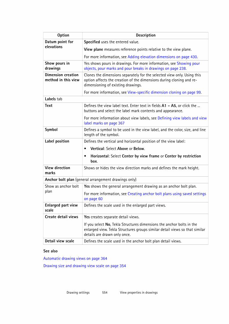
Option DescriptionDatum point forelevations
Specified uses the entered value.
View plane measures reference points relative to the view plane.
For more information, see Adding elevation dimensions on page 430.
Show pours indrawings
Yes shows pours in drawings. For more information, see Showing pourobjects, pour marks and pour breaks in drawings on page 238.
Dimension creationmethod in this view
Clones the dimensions separately for the selected view only. Using thisoption affects the creation of the dimensions during cloning and re-dimensioning of existing drawings.
For more information, see View-specific dimension cloning on page 99.
Labels tab
Text Defines the view label text. Enter text in fields A1 - A5, or click the ...buttons and select the label mark contents and appearance.
For more information about view labels, see Defining view labels and viewlabel marks on page 367
Symbol Defines a symbol to be used in the view label, and the color, size, and linelength of the symbol.
Label position Defines the vertical and horizontal position of the view label:
• Vertical: Select Above or Below.
• Horizontal: Select Center by view frame or Center by restrictionbox.
View directionmarks
Shows or hides the view direction marks and defines the mark height.
Anchor bolt plan (general arrangement drawings only)
Show as anchor boltplan
Yes shows the general arrangement drawing as an anchor bolt plan.
For more information, see Creating anchor bolt plans using saved settingson page 60
Enlarged part viewscale
Defines the scale used in the enlarged part views.
Create detail views Yes creates separate detail views.
If you select No, Tekla Structures dimensions the anchor bolts in theenlarged view. Tekla Structures groups similar detail views so that similardetails are drawn only once.
Detail view scale Defines the scale used in the anchor bolt plan detail views.
See also
Automatic drawing views on page 364
Drawing size and drawing view scale on page 354
Drawing settings 554 View properties in drawings

Defining the views to create in single-part, assembly and cast unit drawings on page 365
Defining automatic view settings for general arrangement drawings on page 366
8.5 Section view properties
When you create automatic section views, Tekla Structures creates section views and sectionmarks using the current properties.
Option Description
Attributes tab
Section depth Defines the positive and negative distances ofthe section view when views are not combined.
Distance for combining cuts Defines the distance range for combining cutviews.
Direction Define the view direction of the section. Theoptions are:
• Right section
• Middle section
• Left section
The available values are left or right.Cutting lineLine Length and offset of the cutting line.
Properties Color of the cutting line.
Section markText Defines the text on the section mark. Click
the ... buttons next to the text boxes to openthe Mark Contents dialog box.
Symbol: Color Color of the section mark symbol.
Left symbol, Right symbol Left and right section mark symbol.
Size Size of the section mark symbol.
x/y Offset of the section mark symbol.
See also
View properties in drawings on page 551
Object protection and placement settings in drawings on page 357
Automatic drawing views on page 364
Defining the views to create in single-part, assembly and cast unit drawings on page 365
Drawing settings 555 Section view properties
Creating a section view on page 120
8.6 Dimension and dimensioning properties
In single-part, assembly and cast unit drawings, automatic dimensioning properties are setseparately for each view you create in the Dimensioning Rule Properties dialog box. ForIntegrated dimensioning type, they are set in the Dimensioning Properties dialog box. Ingeneral arrangement drawings, dimensions can be set both on drawing and view level in theDimension Properties and Dimensioning Properties dialog boxes.
See also
• Dimensioning rule properties on page 409
• General dimension properties on page 556
• Dimension format, precision and unit properties on page 558
• Dimension appearance properties on page 560
• Dimension mark and dimension tag properties on page 560
• General dimensioning properties on page 562
• Part dimensioning properties on page 566
• Position dimensioning properties on page 565
• Bolt dimensioning properties on page 568
• Dimension grouping properties on page 569
• Sub-assembly dimensioning properties on page 570
• Reinforcement dimensioning properties on page 570
• Grid and overall dimensioning properties (GA drawings) on page 571
• Part dimensioning properties (GA drawings) on page 572
General dimension properties
Use the General tab in the Dimension Properties dialog box to view and modify the format,type, unit, precision, extension line, grouping and placing settings of the dimensions.
The drawing level Dimension Properties dialog box and object level Dimension Propertiesdialog box contents differ. The table below contains all options for both dialog boxes.
Option DescriptionDimension types:Straight
Sets the dimension type for straight dimensions.
Drawing settings 556 Dimension and dimensioning properties
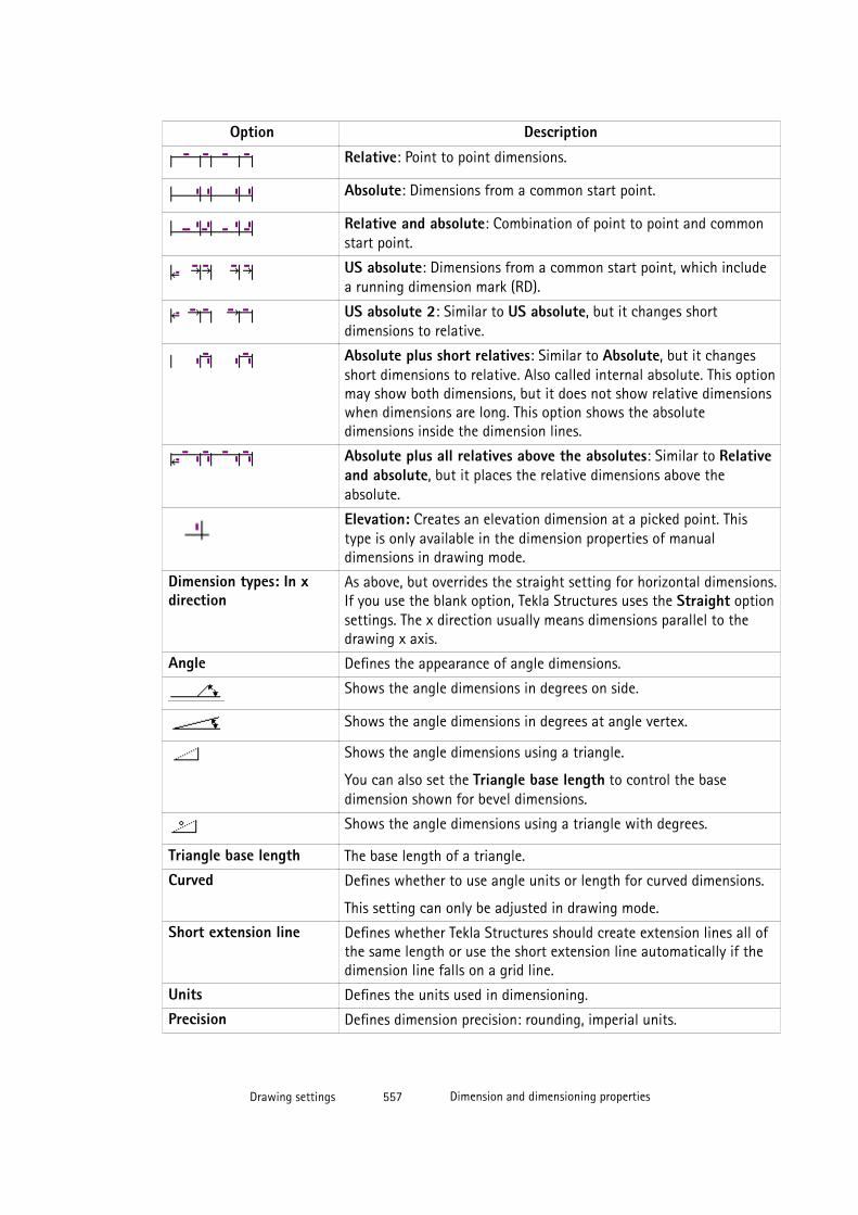
Option Description
Relative: Point to point dimensions.
Absolute: Dimensions from a common start point.
Relative and absolute: Combination of point to point and commonstart point.
US absolute: Dimensions from a common start point, which includea running dimension mark (RD).
US absolute 2: Similar to US absolute, but it changes shortdimensions to relative.
Absolute plus short relatives: Similar to Absolute, but it changesshort dimensions to relative. Also called internal absolute. This optionmay show both dimensions, but it does not show relative dimensionswhen dimensions are long. This option shows the absolutedimensions inside the dimension lines.
Absolute plus all relatives above the absolutes: Similar to Relativeand absolute, but it places the relative dimensions above theabsolute.
Elevation: Creates an elevation dimension at a picked point. Thistype is only available in the dimension properties of manualdimensions in drawing mode.
Dimension types: In xdirection
As above, but overrides the straight setting for horizontal dimensions.If you use the blank option, Tekla Structures uses the Straight optionsettings. The x direction usually means dimensions parallel to thedrawing x axis.
Angle Defines the appearance of angle dimensions.
Shows the angle dimensions in degrees on side.
Shows the angle dimensions in degrees at angle vertex.
Shows the angle dimensions using a triangle.
You can also set the Triangle base length to control the basedimension shown for bevel dimensions.
Shows the angle dimensions using a triangle with degrees.
Triangle base length The base length of a triangle.
Curved Defines whether to use angle units or length for curved dimensions.
This setting can only be adjusted in drawing mode.
Short extension line Defines whether Tekla Structures should create extension lines all ofthe same length or use the short extension line automatically if thedimension line falls on a grid line.
Units Defines the units used in dimensioning.
Precision Defines dimension precision: rounding, imperial units.
Drawing settings 557 Dimension and dimensioning properties
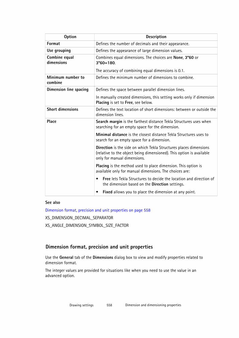
Option DescriptionFormat Defines the number of decimals and their appearance.
Use grouping Defines the appearance of large dimension values.
Combine equaldimensions
Combines equal dimensions. The choices are None, 3*60 or3*60=180.
The accuracy of combining equal dimensions is 0.1.
Minimum number tocombine
Defines the minimum number of dimensions to combine.
Dimension line spacing Defines the space between parallel dimension lines.
In manually created dimensions, this setting works only if dimensionPlacing is set to Free, see below.
Short dimensions Defines the text location of short dimensions: between or outside thedimension lines.
Place Search margin is the farthest distance Tekla Structures uses whensearching for an empty space for the dimension.
Minimal distance is the closest distance Tekla Structures uses tosearch for an empty space for a dimension.
Direction is the side on which Tekla Structures places dimensions(relative to the object being dimensioned). This option is availableonly for manual dimensions.
Placing is the method used to place dimension. This option isavailable only for manual dimensions. The choices are:
• Free lets Tekla Structures to decide the location and direction ofthe dimension based on the Direction settings.
• Fixed allows you to place the dimension at any point.
See also
Dimension format, precision and unit properties on page 558
XS_DIMENSION_DECIMAL_SEPARATOR
XS_ANGLE_DIMENSION_SYMBOL_SIZE_FACTOR
Dimension format, precision and unit properties
Use the General tab of the Dimensions dialog box to view and modify properties related todimension format.
The integer values are provided for situations like when you need to use the value in anadvanced option.
Drawing settings 558 Dimension and dimensioning properties
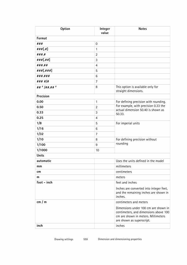
Option Integervalue
Notes
Format
### 0
###[.#] 1
###.# 2
###[.##] 3
###.## 4
###[.###] 5
###.### 6
### #/# 7
## # /##.## # 8 This option is available only forstraight dimensions.
Precision
0.00 1 For defining precision with rounding.For example, with precision 0.33 theactual dimension 50.40 is shown as50.33.
0.50 2
0.33 3
0.25 4
1/8 5 For imperial units
1/16 6
1/32 7
1/10 8 For defining precision withoutrounding1/100 9
1/1000 10
Unitsautomatic Uses the units defined in the model
mm millimeters
cm centimeters
m meters
foot - inch feet and inches
Inches are converted into integer feet,and the remaining inches are shown ininches.
cm / m centimeters and meters
Dimensions under 100 cm are shown incentimeters, and dimensions above 100cm are shown in meters. Millimetersare shown as superscript.
inch inches
Drawing settings 559 Dimension and dimensioning properties
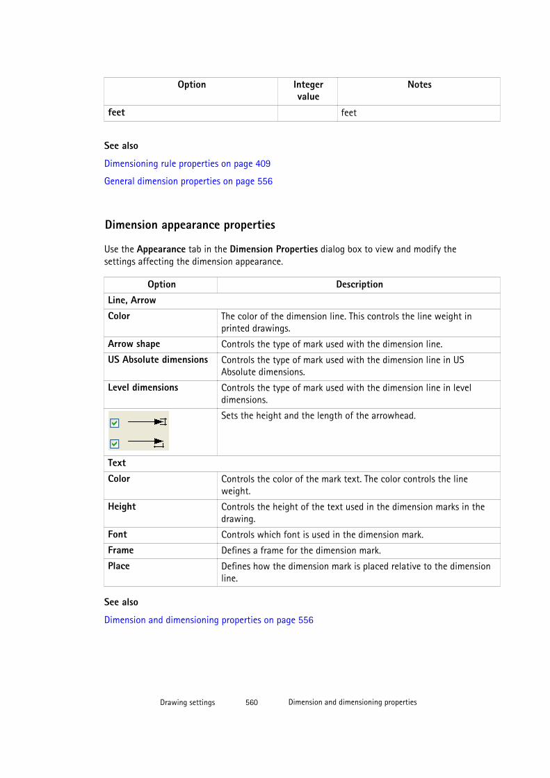
Option Integervalue
Notes
feet feet
See also
Dimensioning rule properties on page 409
General dimension properties on page 556
Dimension appearance properties
Use the Appearance tab in the Dimension Properties dialog box to view and modify thesettings affecting the dimension appearance.
Option DescriptionLine, ArrowColor The color of the dimension line. This controls the line weight in
printed drawings.
Arrow shape Controls the type of mark used with the dimension line.
US Absolute dimensions Controls the type of mark used with the dimension line in USAbsolute dimensions.
Level dimensions Controls the type of mark used with the dimension line in leveldimensions.
Sets the height and the length of the arrowhead.
TextColor Controls the color of the mark text. The color controls the line
weight.
Height Controls the height of the text used in the dimension marks in thedrawing.
Font Controls which font is used in the dimension mark.
Frame Defines a frame for the dimension mark.
Place Defines how the dimension mark is placed relative to the dimensionline.
See also
Dimension and dimensioning properties on page 556
Drawing settings 560 Dimension and dimensioning properties
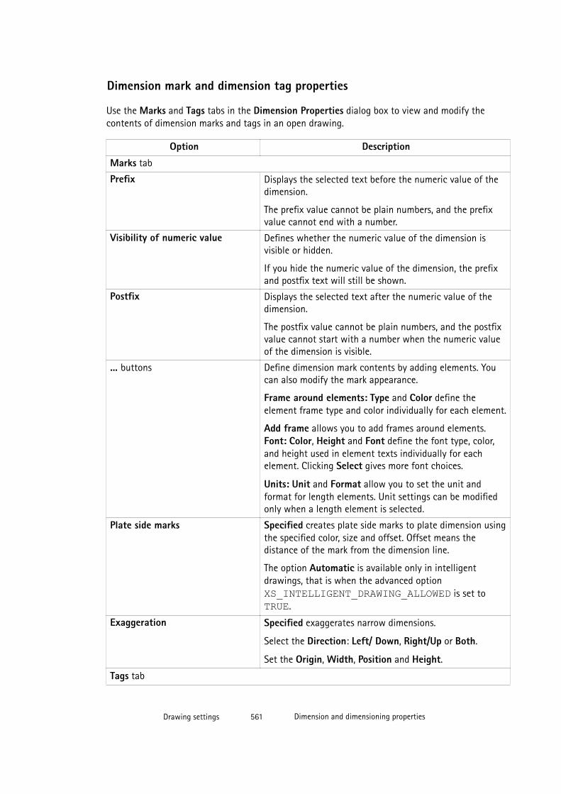
Dimension mark and dimension tag properties
Use the Marks and Tags tabs in the Dimension Properties dialog box to view and modify thecontents of dimension marks and tags in an open drawing.
Option Description
Marks tab
Prefix Displays the selected text before the numeric value of thedimension.
The prefix value cannot be plain numbers, and the prefixvalue cannot end with a number.
Visibility of numeric value Defines whether the numeric value of the dimension isvisible or hidden.
If you hide the numeric value of the dimension, the prefixand postfix text will still be shown.
Postfix Displays the selected text after the numeric value of thedimension.
The postfix value cannot be plain numbers, and the postfixvalue cannot start with a number when the numeric valueof the dimension is visible.
... buttons Define dimension mark contents by adding elements. Youcan also modify the mark appearance.
Frame around elements: Type and Color define theelement frame type and color individually for each element.
Add frame allows you to add frames around elements.Font: Color, Height and Font define the font type, color,and height used in element texts individually for eachelement. Clicking Select gives more font choices.
Units: Unit and Format allow you to set the unit andformat for length elements. Unit settings can be modifiedonly when a length element is selected.
Plate side marks Specified creates plate side marks to plate dimension usingthe specified color, size and offset. Offset means thedistance of the mark from the dimension line.
The option Automatic is available only in intelligentdrawings, that is when the advanced option XS_INTELLIGENT_DRAWING_ALLOWED is set to TRUE.
Exaggeration Specified exaggerates narrow dimensions.
Select the Direction: Left/ Down, Right/Up or Both.
Set the Origin, Width, Position and Height.
Tags tab
Drawing settings 561 Dimension and dimensioning properties

Option Description
Tags area Adds user-defined tags to dimension lines.
... buttons Define dimension tag contents by adding elements. You canalso modify the tag element appearance.
Rotation --> Perpendicular to dimension line rotates thetag.
Rotation --> Parallel to dimension line does not rotatethe tag. This is the default value.
Frame around elements: Type and Color define theelement frame type and color individually for each element.
Add frame allows you to add frames around elements.Font: Color, Height and Font define the font type, color,and height used in element texts individually for eachelement. Clicking Select gives more font choices.
Units: Unit and Format allow you to set the unit andformat for length elements. Unit settings can be modifiedonly when a length element is selected.
Include part count in the tag Yes includes part count in the tag.
Exclude parts according to filter Select a drawing view filter that removes desired contentfrom the tag.
See also
Adding manual dimensions on page 146
Showing plate side marks on page 173
Creating exaggerated dimensions on page 456
Adding tags to dimensions on page 154
Example: Filtering out dimension tag content on page 156
General dimensioning properties
Use the General tab in the Dimensioning Properties dialog box to view and modify thegeneral settings of the dimensions.
Option DescriptionDimensioning type Standard is used for almost all dimensioning.
Truss meets the specific requirements needed to dimension trussdrawings. It dimensions the position and length of the diagonals. Thedimensioning is done only if the diagonals are secondary parts that arewelded to upper and lower chords, which are main parts and not welded
Drawing settings 562 Dimension and dimensioning properties
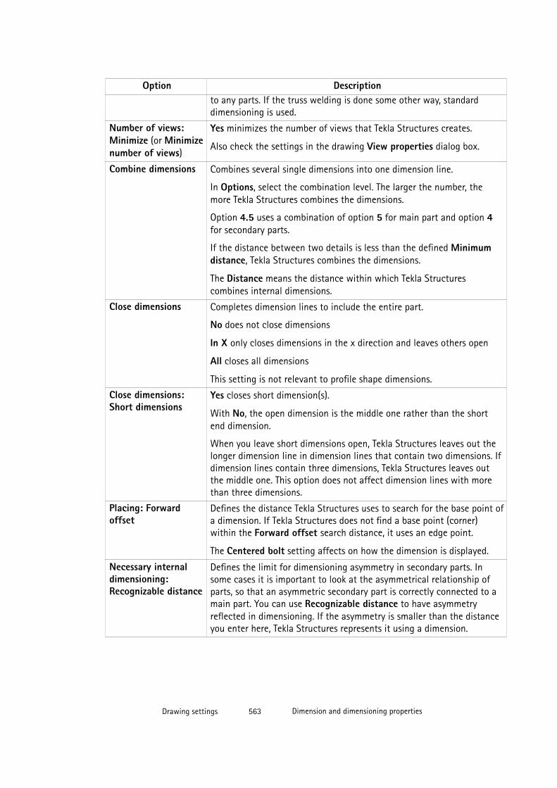
Option Descriptionto any parts. If the truss welding is done some other way, standarddimensioning is used.
Number of views:Minimize (or Minimizenumber of views)
Yes minimizes the number of views that Tekla Structures creates.
Also check the settings in the drawing View properties dialog box.
Combine dimensions Combines several single dimensions into one dimension line.
In Options, select the combination level. The larger the number, themore Tekla Structures combines the dimensions.
Option 4.5 uses a combination of option 5 for main part and option 4for secondary parts.
If the distance between two details is less than the defined Minimumdistance, Tekla Structures combines the dimensions.
The Distance means the distance within which Tekla Structurescombines internal dimensions.
Close dimensions Completes dimension lines to include the entire part.
No does not close dimensions
In X only closes dimensions in the x direction and leaves others open
All closes all dimensions
This setting is not relevant to profile shape dimensions.
Close dimensions:Short dimensions
Yes closes short dimension(s).
With No, the open dimension is the middle one rather than the shortend dimension.
When you leave short dimensions open, Tekla Structures leaves out thelonger dimension line in dimension lines that contain two dimensions. Ifdimension lines contain three dimensions, Tekla Structures leaves outthe middle one. This option does not affect dimension lines with morethan three dimensions.
Placing: Forwardoffset
Defines the distance Tekla Structures uses to search for the base point ofa dimension. If Tekla Structures does not find a base point (corner)within the Forward offset search distance, it uses an edge point.
The Centered bolt setting affects on how the dimension is displayed.
Necessary internaldimensioning:Recognizable distance
Defines the limit for dimensioning asymmetry in secondary parts. Insome cases it is important to look at the asymmetrical relationship ofparts, so that an asymmetric secondary part is correctly connected to amain part. You can use Recognizable distance to have asymmetryreflected in dimensioning. If the asymmetry is smaller than the distanceyou enter here, Tekla Structures represents it using a dimension.
Drawing settings 563 Dimension and dimensioning properties
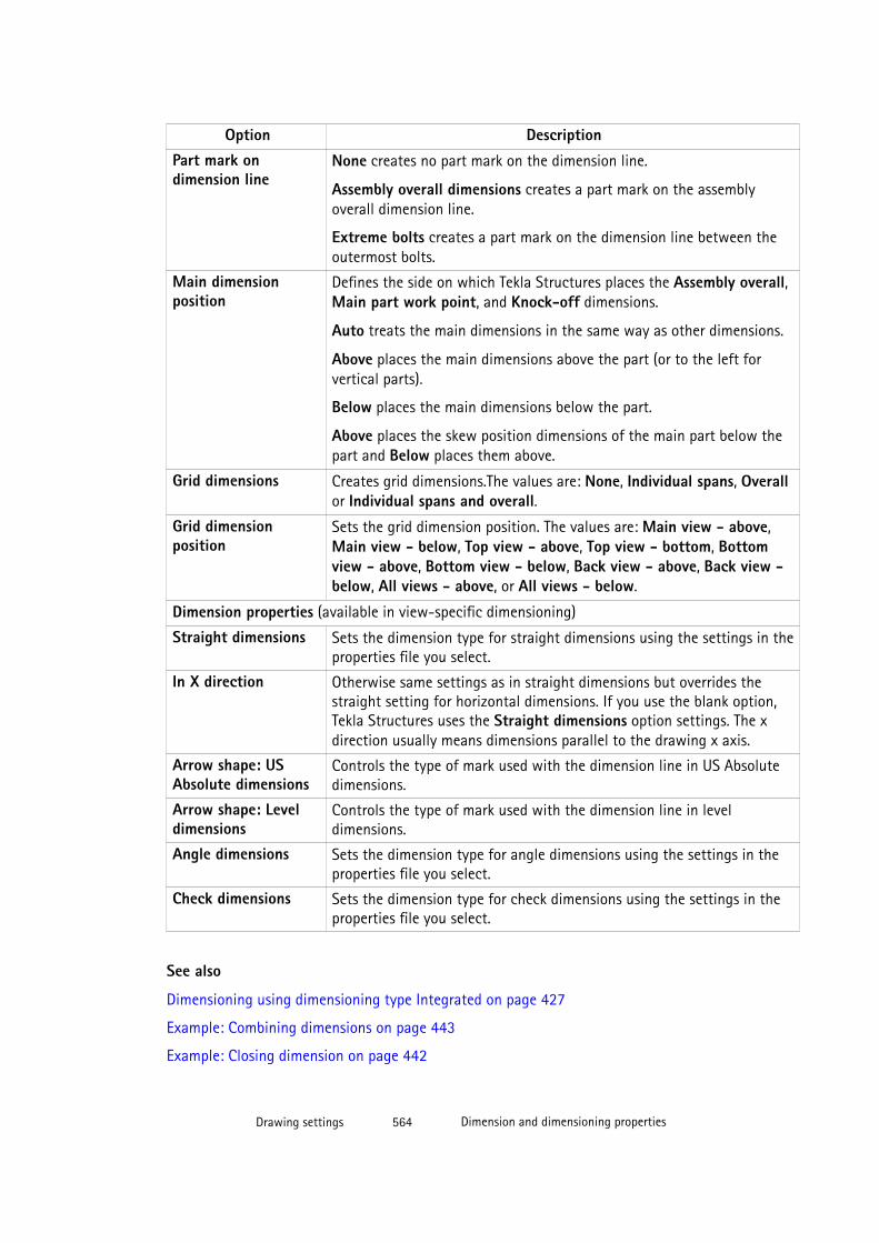
Option DescriptionPart mark ondimension line
None creates no part mark on the dimension line.
Assembly overall dimensions creates a part mark on the assemblyoverall dimension line.
Extreme bolts creates a part mark on the dimension line between theoutermost bolts.
Main dimensionposition
Defines the side on which Tekla Structures places the Assembly overall,Main part work point, and Knock-off dimensions.
Auto treats the main dimensions in the same way as other dimensions.
Above places the main dimensions above the part (or to the left forvertical parts).
Below places the main dimensions below the part.
Above places the skew position dimensions of the main part below thepart and Below places them above.
Grid dimensions Creates grid dimensions.The values are: None, Individual spans, Overallor Individual spans and overall.
Grid dimensionposition
Sets the grid dimension position. The values are: Main view - above,Main view - below, Top view - above, Top view - bottom, Bottomview - above, Bottom view - below, Back view - above, Back view -below, All views - above, or All views - below.
Dimension properties (available in view-specific dimensioning)
Straight dimensions Sets the dimension type for straight dimensions using the settings in theproperties file you select.
In X direction Otherwise same settings as in straight dimensions but overrides thestraight setting for horizontal dimensions. If you use the blank option,Tekla Structures uses the Straight dimensions option settings. The xdirection usually means dimensions parallel to the drawing x axis.
Arrow shape: USAbsolute dimensions
Controls the type of mark used with the dimension line in US Absolutedimensions.
Arrow shape: Leveldimensions
Controls the type of mark used with the dimension line in leveldimensions.
Angle dimensions Sets the dimension type for angle dimensions using the settings in theproperties file you select.
Check dimensions Sets the dimension type for check dimensions using the settings in theproperties file you select.
See also
Dimensioning using dimensioning type Integrated on page 427
Example: Combining dimensions on page 443
Example: Closing dimension on page 442
Drawing settings 564 Dimension and dimensioning properties
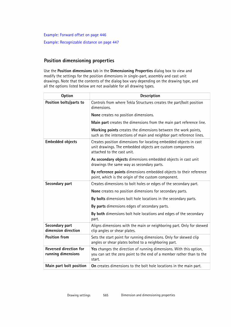
Example: Forward offset on page 446
Example: Recognizable distance on page 447
Position dimensioning properties
Use the Position dimensions tab in the Dimensioning Properties dialog box to view andmodify the settings for the position dimensions in single-part, assembly and cast unitdrawings. Note that the contents of the dialog box vary depending on the drawing type, andall the options listed below are not available for all drawing types.
Option DescriptionPosition bolts/parts to Controls from where Tekla Structures creates the part/bolt position
dimensions.
None creates no position dimensions.
Main part creates the dimensions from the main part reference line.
Working points creates the dimensions between the work points,such as the intersections of main and neighbor part reference lines.
Embedded objects Creates position dimensions for locating embedded objects in castunit drawings. The embedded objects are custom componentsattached to the cast unit.
As secondary objects dimensions embedded objects in cast unitdrawings the same way as secondary parts.
By reference points dimensions embedded objects to their referencepoint, which is the origin of the custom component.
Secondary part Creates dimensions to bolt holes or edges of the secondary part.
None creates no position dimensions for secondary parts.
By bolts dimensions bolt hole locations in the secondary parts.
By parts dimensions edges of secondary parts.
By both dimensions bolt hole locations and edges of the secondarypart.
Secondary partdimension direction
Aligns dimensions with the main or neighboring part. Only for skewedclip angles or shear plates.
Position from Sets the start point for running dimensions. Only for skewed clipangles or shear plates bolted to a neighboring part.
Reversed direction forrunning dimensions
Yes changes the direction of running dimensions. With this option,you can set the zero point to the end of a member rather than to thestart.
Main part bolt position On creates dimensions to the bolt hole locations in the main part.
Drawing settings 565 Dimension and dimensioning properties

Option DescriptionMain part skew position Yes creates horizontal and vertical check dimensions representing the
skew position of a brace. Created between the work points of themain part.
Skew check dimensions are located in the front view. Their locationdepends on the Main dimension side setting selected on the Generaltab. When the main dimensions are above the part, the skewdimensions are below, and vice versa.
Skew position Defines how Tekla Structures dimensions skewed secondary partpositions.
None creates no dimensions for skewed secondary part positions.
Angle creates an angle dimension for the secondary part.
Dimensions creates dimensions for the skewed position of thesecondary part.
Both creates both the angle and the dimensions.
Centered part Controls the dimensions of centrally-placed parts. These settings havean effect only if position dimensions are created.
Internal dimensions the centered parts overall size.
Position dimensions the part to the main part center lines.
None creates no centered part dimensions.
Centered bolt Controls the dimensions of centrally-placed bolt groups.
Internal dimensions the centered bolts spread.
Position dimensions the bolts to the main part center-lines.
Centered bolt overrides the Secondary part bolt internal option forcentered bolts. This only applies to bolts located centrally on the part.
Elevation dimension On creates elevation dimensions.
Combine equaldimensions
Combines equal dimensions. The choices are None, 3*60 or3*60=180.
The accuracy of combining equal dimensions is 0.1.
Minimum number tocombine
Defines the minimum number of dimensions to combine.
See also
Part dimensioning properties
Use the options on the Part dimensioning tab of the Dimensioning Properties dialog box toview and modify part dimensioning settings for single-part, assembly and cast unit drawings.
Drawing settings 566 Dimension and dimensioning properties
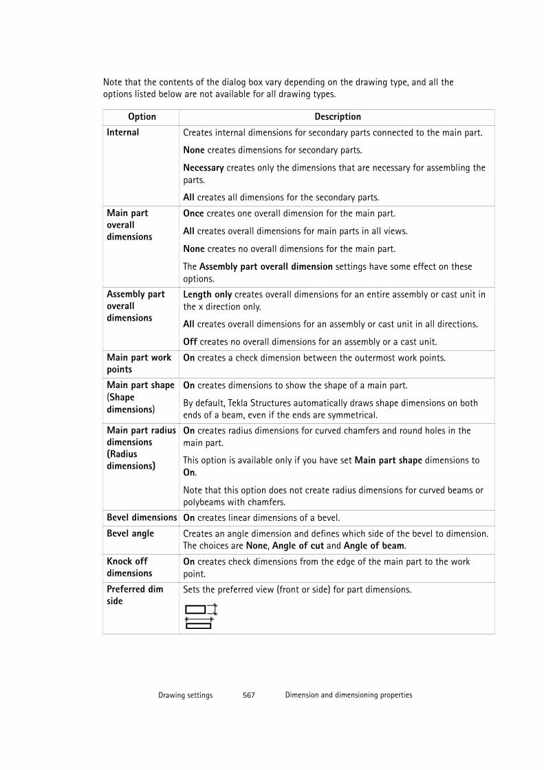
Note that the contents of the dialog box vary depending on the drawing type, and all theoptions listed below are not available for all drawing types.
Option DescriptionInternal Creates internal dimensions for secondary parts connected to the main part.
None creates dimensions for secondary parts.
Necessary creates only the dimensions that are necessary for assembling theparts.
All creates all dimensions for the secondary parts.
Main partoveralldimensions
Once creates one overall dimension for the main part.
All creates overall dimensions for main parts in all views.
None creates no overall dimensions for the main part.
The Assembly part overall dimension settings have some effect on theseoptions.
Assembly partoveralldimensions
Length only creates overall dimensions for an entire assembly or cast unit inthe x direction only.
All creates overall dimensions for an assembly or cast unit in all directions.
Off creates no overall dimensions for an assembly or a cast unit.
Main part workpoints
On creates a check dimension between the outermost work points.
Main part shape(Shapedimensions)
On creates dimensions to show the shape of a main part.
By default, Tekla Structures automatically draws shape dimensions on bothends of a beam, even if the ends are symmetrical.
Main part radiusdimensions(Radiusdimensions)
On creates radius dimensions for curved chamfers and round holes in themain part.
This option is available only if you have set Main part shape dimensions toOn.
Note that this option does not create radius dimensions for curved beams orpolybeams with chamfers.
Bevel dimensions On creates linear dimensions of a bevel.
Bevel angle Creates an angle dimension and defines which side of the bevel to dimension.The choices are None, Angle of cut and Angle of beam.
Knock offdimensions
On creates check dimensions from the edge of the main part to the workpoint.
Preferred dimside
Sets the preferred view (front or side) for part dimensions.
Drawing settings 567 Dimension and dimensioning properties
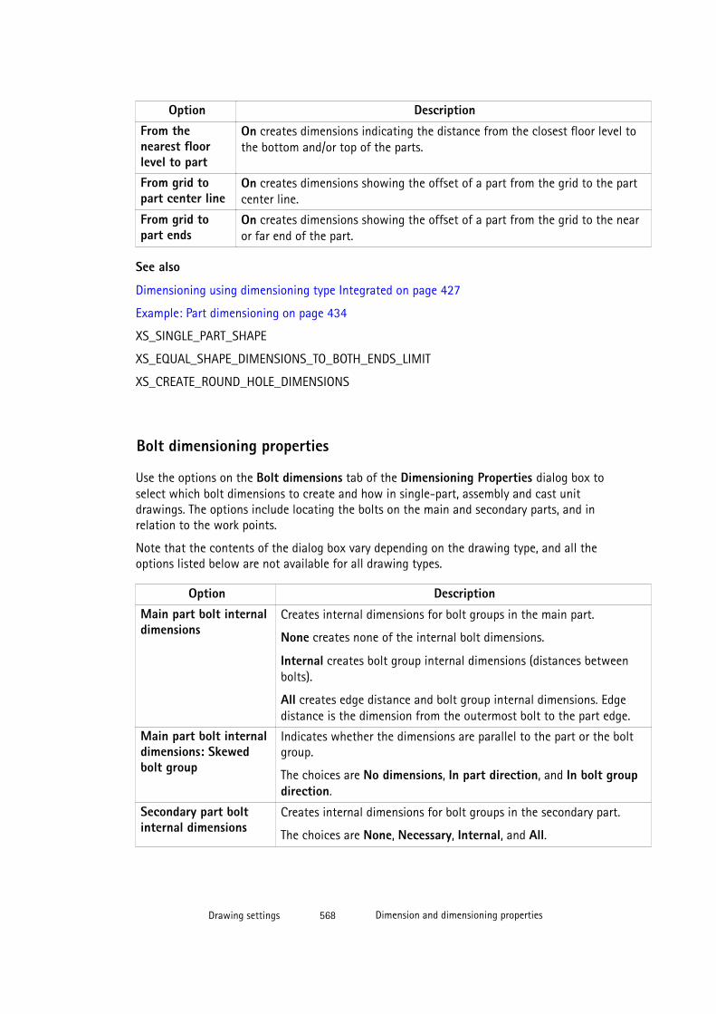
Option DescriptionFrom thenearest floorlevel to part
On creates dimensions indicating the distance from the closest floor level tothe bottom and/or top of the parts.
From grid topart center line
On creates dimensions showing the offset of a part from the grid to the partcenter line.
From grid topart ends
On creates dimensions showing the offset of a part from the grid to the nearor far end of the part.
See also
Dimensioning using dimensioning type Integrated on page 427
Example: Part dimensioning on page 434
XS_SINGLE_PART_SHAPE
XS_EQUAL_SHAPE_DIMENSIONS_TO_BOTH_ENDS_LIMIT
XS_CREATE_ROUND_HOLE_DIMENSIONS
Bolt dimensioning properties
Use the options on the Bolt dimensions tab of the Dimensioning Properties dialog box toselect which bolt dimensions to create and how in single-part, assembly and cast unitdrawings. The options include locating the bolts on the main and secondary parts, and inrelation to the work points.
Note that the contents of the dialog box vary depending on the drawing type, and all theoptions listed below are not available for all drawing types.
Option DescriptionMain part bolt internaldimensions
Creates internal dimensions for bolt groups in the main part.
None creates none of the internal bolt dimensions.
Internal creates bolt group internal dimensions (distances betweenbolts).
All creates edge distance and bolt group internal dimensions. Edgedistance is the dimension from the outermost bolt to the part edge.
Main part bolt internaldimensions: Skewedbolt group
Indicates whether the dimensions are parallel to the part or the boltgroup.
The choices are No dimensions, In part direction, and In bolt groupdirection.
Secondary part boltinternal dimensions
Creates internal dimensions for bolt groups in the secondary part.
The choices are None, Necessary, Internal, and All.
Drawing settings 568 Dimension and dimensioning properties
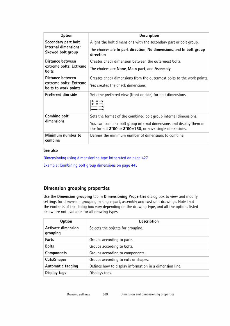
Option DescriptionSecondary part boltinternal dimensions:Skewed bolt group
Aligns the bolt dimensions with the secondary part or bolt group.
The choices are In part direction, No dimensions, and In bolt groupdirection
Distance betweenextreme bolts: Extremebolts
Creates check dimension between the outermost bolts.
The choices are None, Main part, and Assembly.
Distance betweenextreme bolts: Extremebolts to work points
Creates check dimensions from the outermost bolts to the work points.
Yes creates the check dimensions.
Preferred dim side Sets the preferred view (front or side) for bolt dimensions.
Combine boltdimensions
Sets the format of the combined bolt group internal dimensions.
You can combine bolt group internal dimensions and display them inthe format 3*60 or 3*60=180, or have single dimensions.
Minimum number tocombine
Defines the minimum number of dimensions to combine.
See also
Dimensioning using dimensioning type Integrated on page 427
Example: Combining bolt group dimensions on page 445
Dimension grouping propertiesUse the Dimension grouping tab in Dimensioning Properties dialog box to view and modifysettings for dimension grouping in single-part, assembly and cast unit drawings. Note thatthe contents of the dialog box vary depending on the drawing type, and all the options listedbelow are not available for all drawing types.
Option DescriptionActivate dimensiongrouping
Selects the objects for grouping.
Parts Groups according to parts.
Bolts Groups according to bolts.
Components Groups according to components.
Cuts/Shapes Groups according to cuts or shapes.
Automatic tagging Defines how to display information in a dimension line.
Display tags Displays tags.
Drawing settings 569 Dimension and dimensioning properties

Option DescriptionInclude part count inthe tag
Includes part count in the tag.
Do not display marksfor the grouped items
Does not display part marks for grouped items.
Available elements Elements available to define identical conditions.
Add Adds items to Selected elements list.Remove Removes items from Selected elements list.Move up Moves the element higher in the list.
Move down Moves the element lower in the list.
Update grouping whenmodel changes
Yes updates dimension grouping automatically when the modelchanges.
Sub-assembly dimensioning properties
Use the options on the Sub-assembly tab of the Assembly - Dimensioning Properties dialogbox to view and modify which dimensions to create and how for sub-assemblies.
Option DescriptionDimension parts inside sub-assemblies Defines whether to dimension parts inside sub-
assemblies.
Yes creates internal dimensions for parts inside sub-assemblies.
No does not create internal dimensions for parts insidesub-assemblies.
Measure sub-assembly position from Defines the position from which the sub-assembly ismeasured.
None does not measure the sub-assembly position.
Bolt measures the position of the sub-assembly fromthe bolts. If bolts are not included in the sub-assembly,or if it is not possible to measure the position frombolts, Tekla Structures measures the sub-assemblyposition from the reference point.
Extreme points measures the position of the sub-assembly from the bounding box of the sub-assembly.
Reference point measures the position of the sub-assembly from the reference point.
Drawing settings 570 Dimension and dimensioning properties
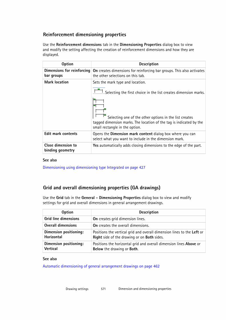
Reinforcement dimensioning properties
Use the Reinforcement dimensions tab in the Dimensioning Properties dialog box to viewand modify the setting affecting the creation of reinforcement dimensions and how they aredisplayed.
Option DescriptionDimensions for reinforcingbar groups
On creates dimensions for reinforcing bar groups. This also activatesthe other selections on this tab.
Mark location Sets the mark type and location.
Selecting the first choice in the list creates dimension marks.
Selecting one of the other options in the list createstagged dimension marks. The location of the tag is indicated by thesmall rectangle in the option.
Edit mark contents Opens the Dimension mark content dialog box where you canselect what you want to include in the dimension mark.
Close dimension tobinding geometry
Yes automatically adds closing dimensions to the edge of the part.
See also
Dimensioning using dimensioning type Integrated on page 427
Grid and overall dimensioning properties (GA drawings)
Use the Grid tab in the General - Dimensioning Properties dialog box to view and modifysettings for grid and overall dimensions in general arrangement drawings.
Option DescriptionGrid line dimensions On creates grid dimension lines.
Overall dimensions On creates the overall dimensions.
Dimension positioning:Horizontal
Positions the vertical grid and overall dimension lines to the Left orRight side of the drawing or on Both sides.
Dimension positioning:Vertical
Positions the horizontal grid and overall dimension lines Above orBelow the drawing or Both.
See also
Automatic dimensioning of general arrangement drawings on page 462
Drawing settings 571 Dimension and dimensioning properties
Part dimensioning properties (GA drawings)
Use the Parts tab in the General - Dimensioning Properties dialog box to view and modifysettings for part dimensions in general arrangement drawings.
Option DescriptionMaximum leader linelength: Outsidedimensions
Controls how close the dimension lines are positioned to the partsthey are dimensioning. Defines that the outside dimension linestake the maximum leader line length from the grid line.
Maximum leader linelength: Inside dimensions
Controls how close the dimension lines are positioned to the partsthey are dimensioning. Defines that the inside dimension lines takethe maximum leader line length from the part reference point.
Include parts not entirelyin view
On dimensions the parts partly outside the view. Off will notdimension these parts.
Maximum number ofoutside dimensions
Specifies the maximum number of dimension lines allowed outsidethe grid. When you dimension different objects on differentdimension lines, using this setting helps you to create cleanerdrawings.
Once the desired maximum is reached, Tekla Structures creates thedimensions inside the grid.
Object groupdimensioning rules
Specifies different object groups to be dimensioned on differentdimension lines.
Object group The object group to be dimensioned.
Positioning No dimensions does not create dimensions for the parts.
Inside grid creates dimensions next to or near the parts beingdimensioned. All part dimensions are placed inside the grid whenthe parts are inside the grid. The dimension will still be outside,even if you have selected Inside grid because of where the parts arein the end bay and the end being dimensioned to is next to theoutside.
Outside grid creates dimensions to parts and positions themoutside the grid.
Either creates dimensions to parts and positions them either insideor outside the grid depending on the part position and the settingof the option Maximum number of outside dimensions.
You must use the Either option if you define the Maximum numberof outside dimensions, so that Tekla Structures can positiondimensions inside the grid when the maximum number ofdimensions is reached outside the grid.
Drawing settings 572 Dimension and dimensioning properties

Option DescriptionHorizontal position Left side positions all dimensions to horizontal parts to the left of
the grid.
Right side positions all dimensions to horizontal parts to the rightof the grid.
Distributed to both sides positions all dimensions to horizontalparts to the grid nearest the part they are dimensioning.
Vertical position Above positions all dimensions to vertical parts above the grid.
Below positions all dimensions to vertical parts below the grid.
Distributed to both sides positions all dimensions to vertical partsto the grid nearest the part they are dimensioning.
See also
Automatic dimensioning of general arrangement drawings on page 462
Example: Part dimension positioning on page 470
Example: Limiting the number of outside dimensions on page 469
Example: Dimensioning parts partly outside the view on page 468
Example: Using maximum leader line length options on page 467
8.7 Mark properties
You can adjust the mark appearance and contents before creating a drawing and also in anopen drawing.
Click the links below to find out more:
• Mark appearance and merging properties on page 573
• Leader line types on page 576
• Positioning properties of view label, section and detail marks on page 577
• Mark appearance and merging properties on page 573
• Drawing weld mark properties on page 578
• Level mark properties on page 582
Drawing settings 573 Mark properties

Mark appearance and merging properties
Use the General and Contents tabs in the Mark properties of different types of marks toview and modify the settings affecting the mark content and appearance. For reinforcementmarks, the corresponding settings are located on the Contents and Appearance tabs.
Note that all the listed settings are not available for all marks.
Option Description
Contents tab:
Frame around elements: Type and Color Defines the element frame type and color forone or several elements element. To select allelements in the list to apply the samemodification to all of them, hold down Shiftand click the last element in the list.
Add frame allows you to add frames aroundelements.
Font: Color, Height and Font Defines the font type, color, and height used inelement texts in one or several elements. Toselect all elements in the list to apply the samemodification to all of them, hold down Shiftand click the last element in the list.
Clicking Select gives more font choices.
Units: Unit and Format Change the unit and format for the length,height, spacing or diameter element that youhave selected from the Elements in mark list.
General or Appearance tab:
Visible In one view creates marks in one view only.
In all views creates marks in all views.
In main parts
In secondary parts
In sub-assembly main parts
In sub-assembly secondary parts
These options are for bolt marks.
Visible displays bolt marks.
Not visible does not display bolt marks.
Visibility in view distributed distributes the marks in the view.Tekla Structures only creates marks that are notvisible in the other views.
always always creates marks in the view,irrespective the settings in other views.
preferred acts as distributed, but the preferredview has a higher priority.
Select preferred to one view only in a drawing.If you set other views to distributed, the marks
Drawing settings 574 Mark properties
Option Descriptionare located only in the view that has the settingVisibility in view set to preferred.
none creates no marks.
Parts out of view plane This option is available only in view levelproperties.
Visible displays marks outside of the view in thedrawing.
Not visible displays no marks outside the view.
Bolt size limit This option is for bolt marks.
Filters standard-sized bolt marks out ofdrawings. Tekla Structures does not display boltmarks of the size you enter here.
There are several variables that affect the Boltsize limit, see the See also list below.
Merge marks This option is for part marks and surfacetreatment marks.
On merges marks.
Frame around mark: Type and Color Define the frame to be used around marks, andthe color of the frame.
Leader line: Type, Arrow and Use hidden linesfor hidden parts.
Define the leader line type and line arrow type,and select to hide leader lines for hidden parts.
Place Placing: free allowsTekla Structures to searchfor the first suitable location for the mark.
Placing: fixed allows you to place the mark inany location.
When you use the option fixed, the mark stayswhere it is even though you update thedrawing, whereas with free, Tekla Structurestries to find the optimal place for theannotation object.
Search margin is the distance within whichTekla Structures searches for a space to place amark.
Drawing settings 575 Mark properties

Option DescriptionMinimal Distance is the minimum distance ofthe mark from the part.
Quarter defines the areas Tekla Structuressearches for a space to place the mark.
Use the Merging tab in the Cast Unit - Reinforcement Mark Properties dialog box to viewand modify the settings affecting the merging of the reinforcement marks in cast unitdrawings.
Option Image DescriptionIdentical marks insame cast unit
One leader line per row merges the marks andcreates one leader line for a row of reinforcing bars.
Parallel leader lines merges the marks and createsparallel leader lines.
Leader lines to one point merges the marks anddraws all leader lines to one point.
No merge does not merge marks. Tekla Structurescreates an individual leader line for each mark.
If you select No merge, you still need to define themark content for the marks that Tekla Structuresautomatically merges on the Merging tab.
Preferred mergedirection
Merge vertically merges the marks in the verticaldirection of the drawing.
Merge horizontally merges the marks in thehorizontal direction of the drawing.
See also
Automatic mark settings on page 479
Adding automatic marks on page 480
Defining view labels and view label marks on page 367
Modifying section properties on page 142
XS_OMITTED_DIAMETER_TYPE
XS_OMITTED_BOLT_TYPE
XS_OMITTED_BOLT_ASSEMBLY_TYPE
Elements in merged reinforcement marks on page 589
Merging reinforcement marks automatically on page 493
Drawing settings 576 Mark properties
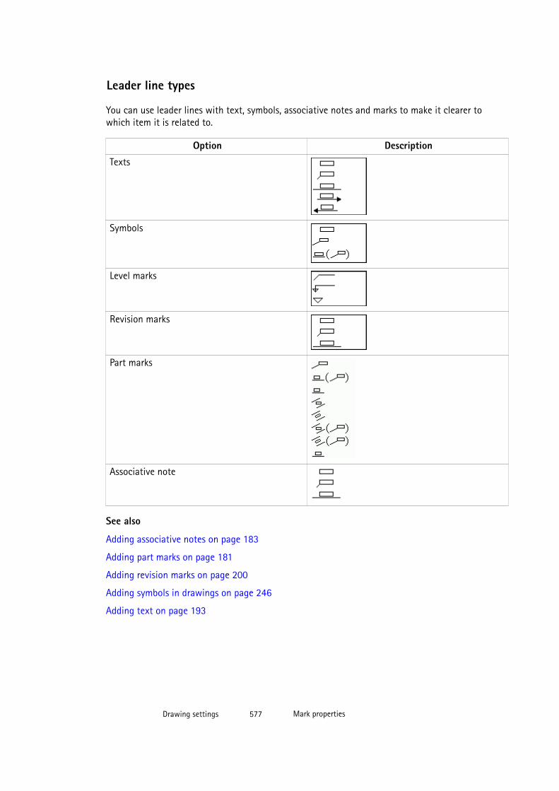
Leader line types
You can use leader lines with text, symbols, associative notes and marks to make it clearer towhich item it is related to.
Option Description
Texts
Symbols
Level marks
Revision marks
Part marks
Associative note
See also
Adding associative notes on page 183
Adding part marks on page 181
Adding revision marks on page 200
Adding symbols in drawings on page 246
Adding text on page 193
Drawing settings 577 Mark properties
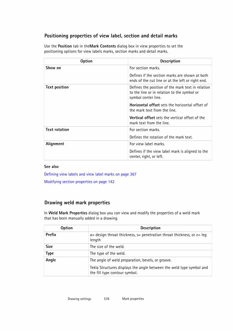
Positioning properties of view label, section and detail marks
Use the Position tab in theMark Contents dialog box in view properties to set thepositioning options for view labels marks, section marks and detail marks.
Option DescriptionShow on For section marks.
Defines if the section marks are shown at bothends of the cut line or at the left or right end.
Text position Defines the position of the mark text in relationto the line or in relation to the symbol orsymbol center line.
Horizontal offset sets the horizontal offset ofthe mark text from the line.
Vertical offset sets the vertical offset of themark text from the line.
Text rotation For section marks.
Defines the rotation of the mark text.
Alignment For view label marks.
Defines if the view label mark is aligned to thecenter, right, or left.
See also
Defining view labels and view label marks on page 367
Modifying section properties on page 142
Drawing weld mark properties
In Weld Mark Properties dialog box you can view and modify the properties of a weld markthat has been manually added in a drawing.
Option DescriptionPrefix a= design throat thickness, s= penetration throat thickness, or z= leg
length
Size The size of the weld.
Type The type of the weld.
Angle The angle of weld preparation, bevels, or groove.
Tekla Structures displays the angle between the weld type symbol andthe fill type contour symbol.
Drawing settings 578 Mark properties
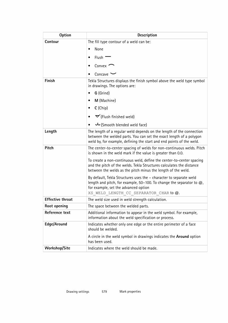
Option DescriptionContour The fill type contour of a weld can be:
• None
• Flush
• Convex
• Concave
Finish Tekla Structures displays the finish symbol above the weld type symbolin drawings. The options are:
• G (Grind)
• M (Machine)
• C (Chip)
• (Flush finished weld)
• (Smooth blended weld face)
Length The length of a regular weld depends on the length of the connectionbetween the welded parts. You can set the exact length of a polygonweld by, for example, defining the start and end points of the weld.
Pitch The center-to-center spacing of welds for non-continuous welds. Pitchis shown in the weld mark if the value is greater than 0.0.
To create a non-continuous weld, define the center-to-center spacingand the pitch of the welds. Tekla Structures calculates the distancebetween the welds as the pitch minus the length of the weld.
By default, Tekla Structures uses the – character to separate weldlength and pitch, for example, 50–100. To change the separator to @,for example, set the advanced option XS_WELD_LENGTH_CC_SEPARATOR_CHAR to @.
Effective throat The weld size used in weld strength calculation.
Root opening The space between the welded parts.
Reference text Additional information to appear in the weld symbol. For example,information about the weld specification or process.
Edge/Around Indicates whether only one edge or the entire perimeter of a faceshould be welded.
A circle in the weld symbol in drawings indicates the Around optionhas been used.
Workshop/Site Indicates where the weld should be made.
Drawing settings 579 Mark properties
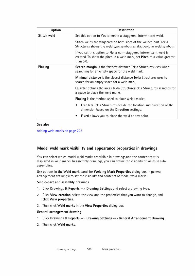
Option DescriptionStitch weld Set this option to Yes to create a staggered, intermittent weld.
Stitch welds are staggered on both sides of the welded part. TeklaStructures shows the weld type symbols as staggered in weld symbols.
If you set this option to No, a non- staggered intermittent weld iscreated. To show the pitch in a weld mark, set Pitch to a value greaterthan 0.0.
Placing Search margin is the farthest distance Tekla Structures uses whensearching for an empty space for the weld mark.
Minimal distance is the closest distance Tekla Structures uses tosearch for an empty space for a weld mark.
Quarter defines the areas Tekla StructuresTekla Structures searches fora space to place the weld marks.
Placing is the method used to place welds marks:
• Free lets Tekla Structures decide the location and direction of thedimension based on the Direction settings.
• Fixed allows you to place the weld at any point.
See also
Adding weld marks on page 223
Model weld mark visibility and appearance properties in drawings
You can select which model weld marks are visible in drawings,and the content that isdisplayed in weld marks. In assembly drawings, you can define the visibility of welds in sub-assemblies.
Use options in the Weld mark panel (or Welding Mark Properties dialog box in generalarrangement drawings) to set the visibility and contents of model weld marks.
Single-part and assembly drawings
1. Click Drawings & Reports --> Drawing Settings and select a drawing type.
2. Click View creation, select the view and the properties that you want to change, andclick View properties.
3. Then click Weld marks in the View Properties dialog box.
General arrangement drawing
1. Click Drawings & Reports --> Drawing Settings --> General Arrangement Drawing .
2. Then click Weld marks.
Drawing settings 580 Mark properties
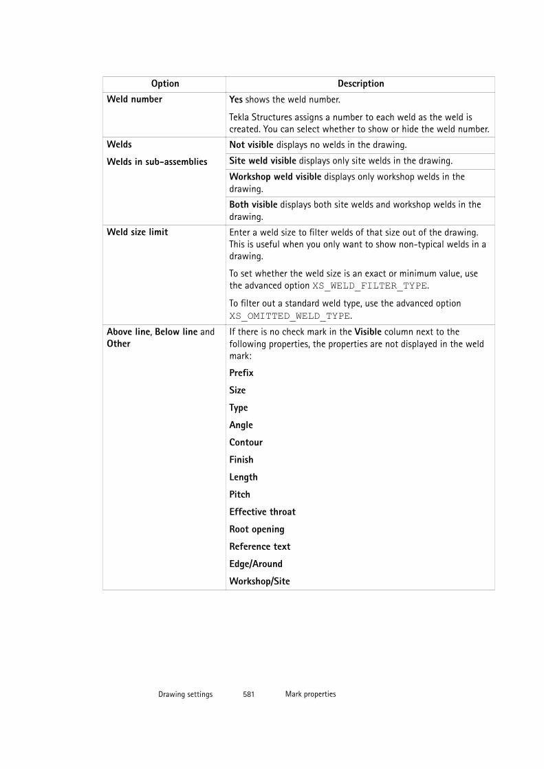
Option DescriptionWeld number Yes shows the weld number.
Tekla Structures assigns a number to each weld as the weld iscreated. You can select whether to show or hide the weld number.
Welds
Welds in sub-assemblies
Not visible displays no welds in the drawing.
Site weld visible displays only site welds in the drawing.
Workshop weld visible displays only workshop welds in thedrawing.
Both visible displays both site welds and workshop welds in thedrawing.
Weld size limit Enter a weld size to filter welds of that size out of the drawing.This is useful when you only want to show non-typical welds in adrawing.
To set whether the weld size is an exact or minimum value, usethe advanced option XS_WELD_FILTER_TYPE.
To filter out a standard weld type, use the advanced option XS_OMITTED_WELD_TYPE.
Above line, Below line andOther
If there is no check mark in the Visible column next to thefollowing properties, the properties are not displayed in the weldmark:
Prefix
Size
Type
Angle
Contour
Finish
Length
Pitch
Effective throat
Root opening
Reference text
Edge/Around
Workshop/Site
Drawing settings 581 Mark properties
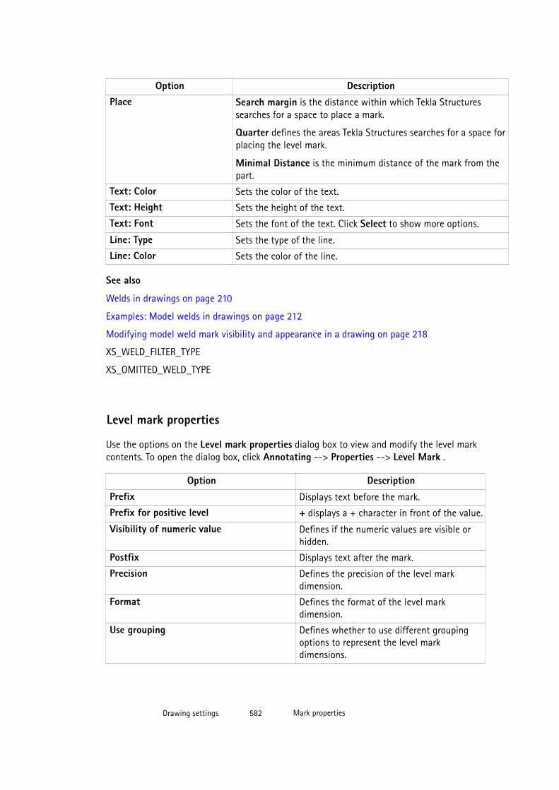
Option DescriptionPlace Search margin is the distance within which Tekla Structures
searches for a space to place a mark.
Quarter defines the areas Tekla Structures searches for a space forplacing the level mark.
Minimal Distance is the minimum distance of the mark from thepart.
Text: Color Sets the color of the text.
Text: Height Sets the height of the text.
Text: Font Sets the font of the text. Click Select to show more options.
Line: Type Sets the type of the line.
Line: Color Sets the color of the line.
See also
Welds in drawings on page 210
Examples: Model welds in drawings on page 212
Modifying model weld mark visibility and appearance in a drawing on page 218
XS_WELD_FILTER_TYPE
XS_OMITTED_WELD_TYPE
Level mark properties
Use the options on the Level mark properties dialog box to view and modify the level markcontents. To open the dialog box, click Annotating --> Properties --> Level Mark .
Option DescriptionPrefix Displays text before the mark.
Prefix for positive level + displays a + character in front of the value.
Visibility of numeric value Defines if the numeric values are visible orhidden.
Postfix Displays text after the mark.
Precision Defines the precision of the level markdimension.
Format Defines the format of the level markdimension.
Use grouping Defines whether to use different groupingoptions to represent the level markdimensions.
Drawing settings 582 Mark properties
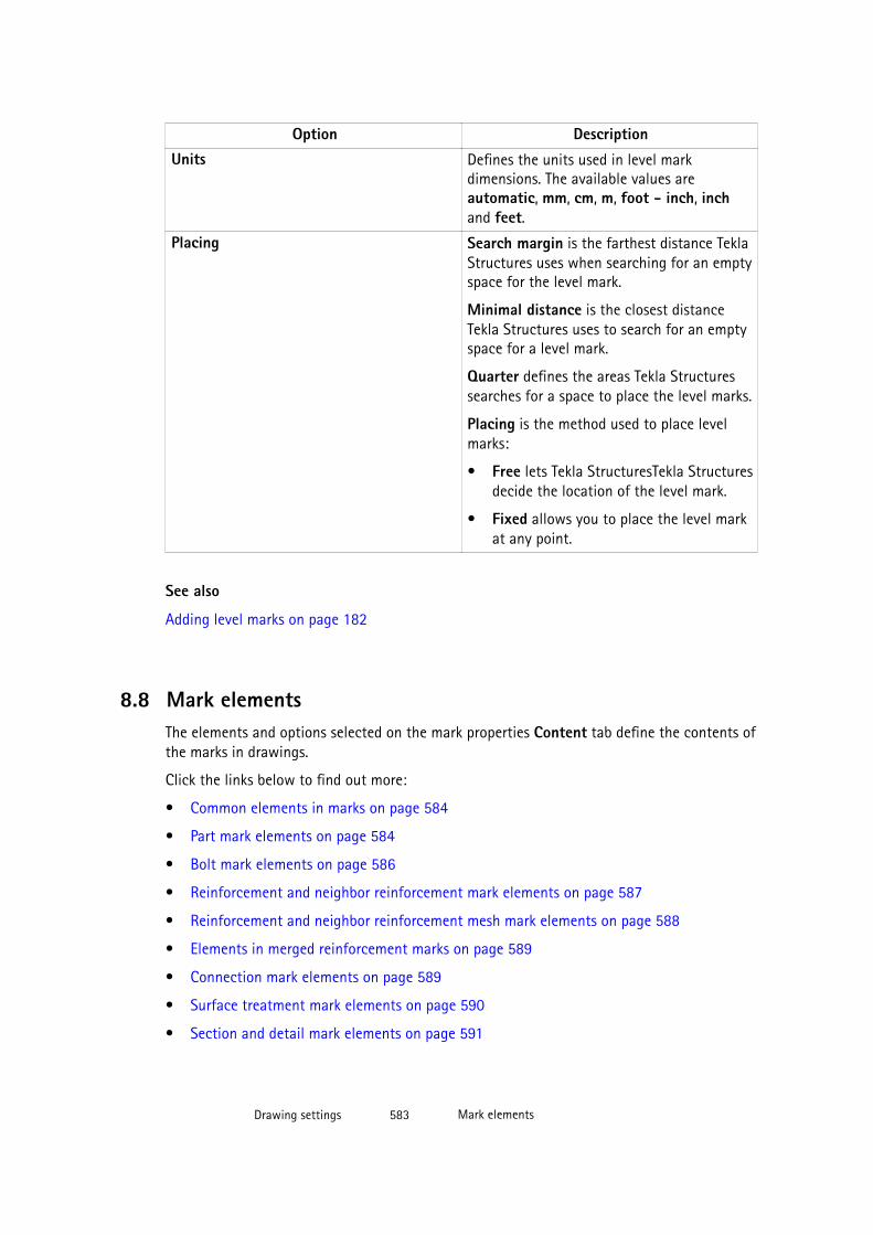
Option DescriptionUnits Defines the units used in level mark
dimensions. The available values areautomatic, mm, cm, m, foot - inch, inchand feet.
Placing Search margin is the farthest distance TeklaStructures uses when searching for an emptyspace for the level mark.
Minimal distance is the closest distanceTekla Structures uses to search for an emptyspace for a level mark.
Quarter defines the areas Tekla Structuressearches for a space to place the level marks.
Placing is the method used to place levelmarks:
• Free lets Tekla StructuresTekla Structuresdecide the location of the level mark.
• Fixed allows you to place the level markat any point.
See also
Adding level marks on page 182
8.8 Mark elementsThe elements and options selected on the mark properties Content tab define the contents ofthe marks in drawings.
Click the links below to find out more:
• Common elements in marks on page 584
• Part mark elements on page 584
• Bolt mark elements on page 586
• Reinforcement and neighbor reinforcement mark elements on page 587
• Reinforcement and neighbor reinforcement mesh mark elements on page 588
• Elements in merged reinforcement marks on page 589
• Connection mark elements on page 589
• Surface treatment mark elements on page 590
• Section and detail mark elements on page 591
Drawing settings 583 Mark elements
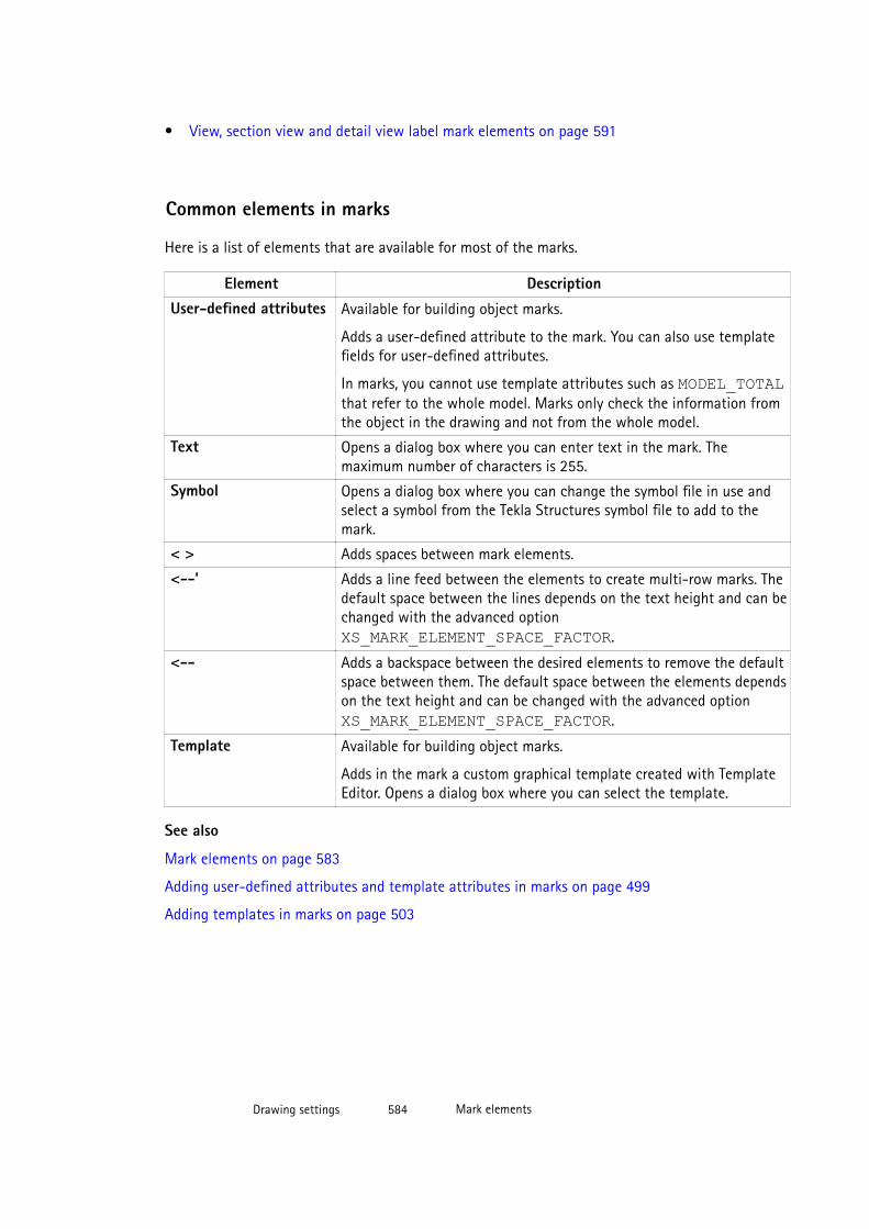
• View, section view and detail view label mark elements on page 591
Common elements in marks
Here is a list of elements that are available for most of the marks.
Element DescriptionUser-defined attributes Available for building object marks.
Adds a user-defined attribute to the mark. You can also use templatefields for user-defined attributes.
In marks, you cannot use template attributes such as MODEL_TOTALthat refer to the whole model. Marks only check the information fromthe object in the drawing and not from the whole model.
Text Opens a dialog box where you can enter text in the mark. Themaximum number of characters is 255.
Symbol Opens a dialog box where you can change the symbol file in use andselect a symbol from the Tekla Structures symbol file to add to themark.
< > Adds spaces between mark elements.
<--’ Adds a line feed between the elements to create multi-row marks. Thedefault space between the lines depends on the text height and can bechanged with the advanced option XS_MARK_ELEMENT_SPACE_FACTOR.
<-- Adds a backspace between the desired elements to remove the defaultspace between them. The default space between the elements dependson the text height and can be changed with the advanced option XS_MARK_ELEMENT_SPACE_FACTOR.
Template Available for building object marks.
Adds in the mark a custom graphical template created with TemplateEditor. Opens a dialog box where you can select the template.
See also
Mark elements on page 583
Adding user-defined attributes and template attributes in marks on page 499
Adding templates in marks on page 503
Drawing settings 584 Mark elements
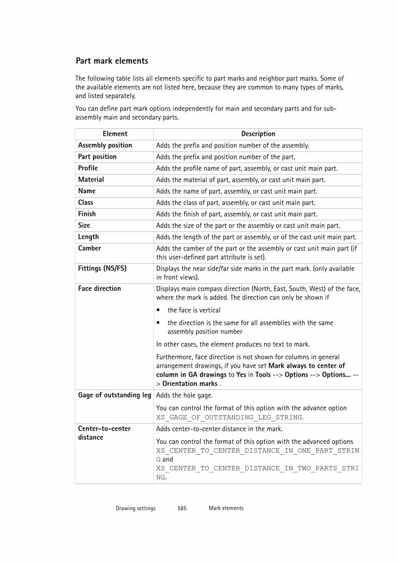
Part mark elements
The following table lists all elements specific to part marks and neighbor part marks. Some ofthe available elements are not listed here, because they are common to many types of marks,and listed separately.
You can define part mark options independently for main and secondary parts and for sub-assembly main and secondary parts.
Element DescriptionAssembly position Adds the prefix and position number of the assembly.
Part position Adds the prefix and position number of the part.
Profile Adds the profile name of part, assembly, or cast unit main part.
Material Adds the material of part, assembly, or cast unit main part.
Name Adds the name of part, assembly, or cast unit main part.
Class Adds the class of part, assembly, or cast unit main part.
Finish Adds the finish of part, assembly, or cast unit main part.
Size Adds the size of the part or the assembly or cast unit main part.
Length Adds the length of the part or assembly, or of the cast unit main part.
Camber Adds the camber of the part or the assembly or cast unit main part (ifthis user-defined part attribute is set).
Fittings (NS/FS) Displays the near side/far side marks in the part mark. (only availablein front views).
Face direction Displays main compass direction (North, East, South, West) of the face,where the mark is added. The direction can only be shown if
• the face is vertical
• the direction is the same for all assemblies with the sameassembly position number
In other cases, the element produces no text to mark.
Furthermore, face direction is not shown for columns in generalarrangement drawings, if you have set Mark always to center ofcolumn in GA drawings to Yes in Tools --> Options --> Options... --> Orientation marks .
Gage of outstanding leg Adds the hole gage.
You can control the format of this option with the advance option XS_GAGE_OF_OUTSTANDING_LEG_STRING.
Center-to-centerdistance
Adds center-to-center distance in the mark.
You can control the format of this option with the advanced options XS_CENTER_TO_CENTER_DISTANCE_IN_ONE_PART_STRING and XS_CENTER_TO_CENTER_DISTANCE_IN_TWO_PARTS_STRING.
Drawing settings 585 Mark elements

See also
Mark elements on page 583
Common elements in marks on page 584
XS_GAGE_OF_OUTSTANDING_LEG_STRING
XS_CENTER_TO_CENTER_DISTANCE_IN_ONE_PART_STRING
XS_CENTER_TO_CENTER_DISTANCE_IN_TWO_PARTS_STRING
ASSEMBLY_BOTTOM_LEVEL
ASSEMBLY_TOP_LEVEL
TOP_LEVEL
BOTTOM_LEVEL
Bolt mark elements
Here is a list of the elements specific to part marks and neighbor part marks. Some of theavailable elements are not listed here, because they are common to many types of marks, andlisted separately.
You can define bolt mark options independently for site and shop bolts.
Element DescriptionBolt length Adds the length of the bolt.
Bolt diameter Adds the bolt diameter.
Hole diameter Adds the hole diameter.
Material Adds the bolt material grade.
Standard Adds the bolt standard.
Short name Adds the bolt’s short name. This can be the commercial name of aspecific bolt, for example.
Full name Adds the complete name of the bolt. This name is visible in the dialogbox list.
Assembly type Adds the bolt’s assembly type.
Number of bolts Adds the quantity of bolts.
Slot length (x, y) Adds the slot’s length in the x or y direction.
Slot length Adds the slot’s length..
Slot height Adds the slot’s height.
Size Adds the hole size.
Countersunk Adds countersink in the countersunk bolt marks.
Drawing settings 586 Mark elements
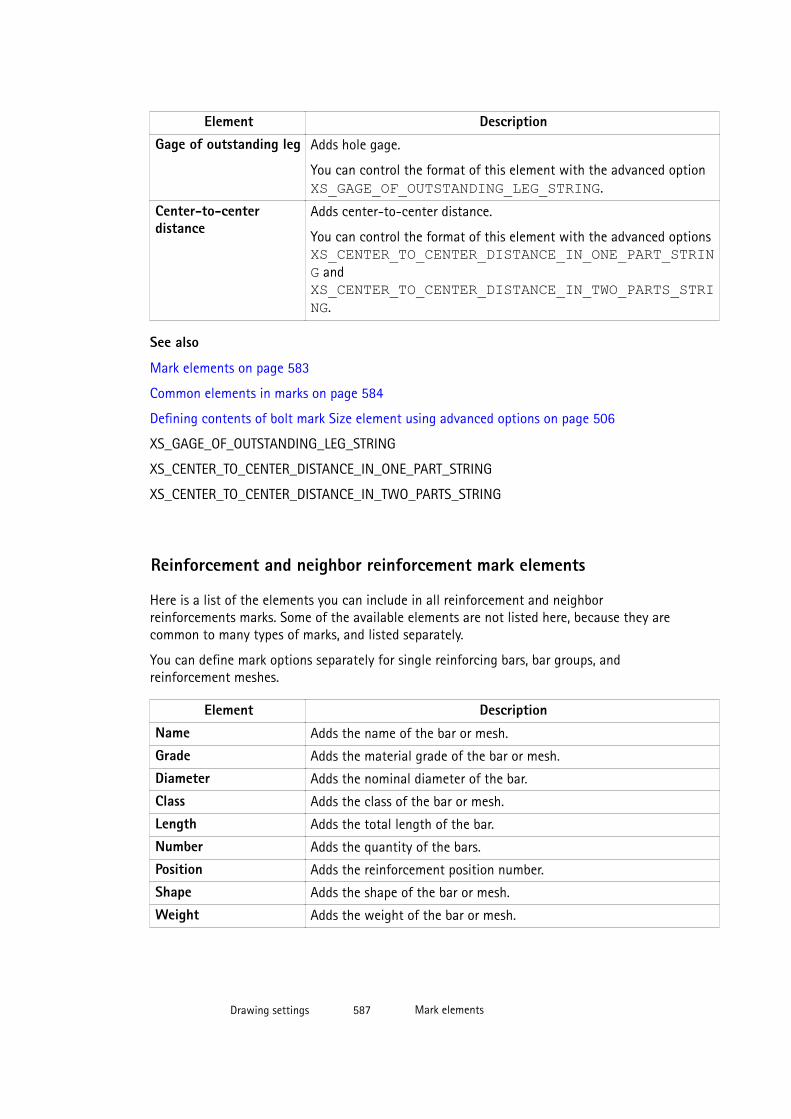
Element DescriptionGage of outstanding leg Adds hole gage.
You can control the format of this element with the advanced option XS_GAGE_OF_OUTSTANDING_LEG_STRING.
Center-to-centerdistance
Adds center-to-center distance.
You can control the format of this element with the advanced options XS_CENTER_TO_CENTER_DISTANCE_IN_ONE_PART_STRING and XS_CENTER_TO_CENTER_DISTANCE_IN_TWO_PARTS_STRING.
See also
Mark elements on page 583
Common elements in marks on page 584
Defining contents of bolt mark Size element using advanced options on page 506
XS_GAGE_OF_OUTSTANDING_LEG_STRING
XS_CENTER_TO_CENTER_DISTANCE_IN_ONE_PART_STRING
XS_CENTER_TO_CENTER_DISTANCE_IN_TWO_PARTS_STRING
Reinforcement and neighbor reinforcement mark elements
Here is a list of the elements you can include in all reinforcement and neighborreinforcements marks. Some of the available elements are not listed here, because they arecommon to many types of marks, and listed separately.
You can define mark options separately for single reinforcing bars, bar groups, andreinforcement meshes.
Element DescriptionName Adds the name of the bar or mesh.
Grade Adds the material grade of the bar or mesh.
Diameter Adds the nominal diameter of the bar.
Class Adds the class of the bar or mesh.
Length Adds the total length of the bar.
Number Adds the quantity of the bars.
Position Adds the reinforcement position number.
Shape Adds the shape of the bar or mesh.
Weight Adds the weight of the bar or mesh.
Drawing settings 587 Mark elements
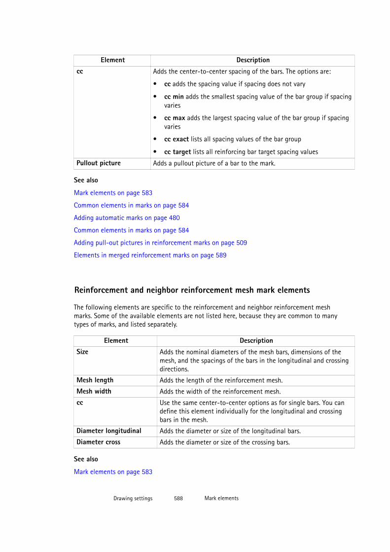
Element Descriptioncc Adds the center-to-center spacing of the bars. The options are:
• cc adds the spacing value if spacing does not vary
• cc min adds the smallest spacing value of the bar group if spacingvaries
• cc max adds the largest spacing value of the bar group if spacingvaries
• cc exact lists all spacing values of the bar group
• cc target lists all reinforcing bar target spacing values
Pullout picture Adds a pullout picture of a bar to the mark.
See also
Mark elements on page 583
Common elements in marks on page 584
Adding automatic marks on page 480
Common elements in marks on page 584
Adding pull-out pictures in reinforcement marks on page 509
Elements in merged reinforcement marks on page 589
Reinforcement and neighbor reinforcement mesh mark elements
The following elements are specific to the reinforcement and neighbor reinforcement meshmarks. Some of the available elements are not listed here, because they are common to manytypes of marks, and listed separately.
Element DescriptionSize Adds the nominal diameters of the mesh bars, dimensions of the
mesh, and the spacings of the bars in the longitudinal and crossingdirections.
Mesh length Adds the length of the reinforcement mesh.
Mesh width Adds the width of the reinforcement mesh.
cc Use the same center-to-center options as for single bars. You candefine this element individually for the longitudinal and crossingbars in the mesh.
Diameter longitudinal Adds the diameter or size of the longitudinal bars.
Diameter cross Adds the diameter or size of the crossing bars.
See also
Mark elements on page 583
Drawing settings 588 Mark elements

Common elements in marks on page 584
Adding automatic marks on page 480
Reinforcement and neighbor reinforcement mark elements on page 587
Elements in merged reinforcement marks
Merged marks can contain the following elements:
Element DescriptionBlock prefix Adds text or a value to the beginning of each repeated
block. Opens a dialog box where you can enter the prefix.
You can use the following variables as block prefixes:
%NUMBER% includes the number of marks merged to themark.
%NUMBER_IN_PLANE% includes the number of marksmerged in the plane of the drawing to the mark.
%NUMBER_OUT_OF_PLANE% includes the number ofmarks merged in the depth direction of the drawing tothe mark.
Single mark content Adds the content of the single reinforcement markselected on the Content tab to the mark.
Distance between groups Adds the center-to-center distances between reinforcingbars or bar groups included in a merged mark.
Symbol separating blocks in mark Adds a symbol between the blocks in the merged mark.Opens a dialog box where you can enter the symbol.
The elements that appear before this element on themark content list generate a block.
See also
Mark elements on page 583
Adding automatic marks on page 480
Merging reinforcement marks automatically on page 493
Drawing settings 589 Mark elements

Connection mark elements
Below is a list of elements specific to connection marks. Some of the available elements arenot listed here, because they are common to many types of marks, and listed separately:Common elements in marks on page 584.
Element DescriptionCode Adds the connection code. This is a user-defined code you give for the
connection in the connection dialog box. The code can be either a textstring or a number.
Name Adds the connection name, for example, Tube_splice.
DSTV code Adds the DSTV code.
Connection number Adds the number of the connection.
Running number Adds the connection running number. All connections areautomatically numbered with a running number, for example, 85.
Group Adds the connection group.
Connection error Adds the connection error. The numbers correspond to the connectionsymbol colors:
• 1 = green
• 2 = yellow
• 3 = red symbol
See also
Mark elements on page 583
Adding automatic marks on page 480
Surface treatment mark elements
Here is a list of elements specific to surface treatment marks. Some of the available elementsare not listed here, because they are common to many types of marks, and listed separately.
Element DescriptionName Adds the name defined in the Name box in the Surface
treatment properties dialog box.
Material Adds the surface treatment material.
Class Adds the class of the surface treatment.
Code Adds the code of the surface treatment.
Surface treatment name Adds the name selected from the Surface treatment name listin the Surface treatment properties dialog box.
Drawing settings 590 Mark elements
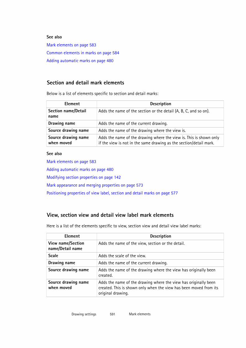
See also
Mark elements on page 583
Common elements in marks on page 584
Adding automatic marks on page 480
Section and detail mark elements
Below is a list of elements specific to section and detail marks:
Element DescriptionSection name/Detailname
Adds the name of the section or the detail (A, B, C, and so on).
Drawing name Adds the name of the current drawing.
Source drawing name Adds the name of the drawing where the view is.
Source drawing namewhen moved
Adds the name of the drawing where the view is. This is shown onlyif the view is not in the same drawing as the section/detail mark.
See also
Mark elements on page 583
Adding automatic marks on page 480
Modifying section properties on page 142
Mark appearance and merging properties on page 573
Positioning properties of view label, section and detail marks on page 577
View, section view and detail view label mark elements
Here is a list of the elements specific to view, section view and detail view label marks:
Element DescriptionView name/Sectionname/Detail name
Adds the name of the view, section or the detail.
Scale Adds the scale of the view.
Drawing name Adds the name of the current drawing.
Source drawing name Adds the name of the drawing where the view has originally beencreated.
Source drawing namewhen moved
Adds the name of the drawing where the view has originally beencreated. This is shown only when the view has been moved from itsoriginal drawing.
Drawing settings 591 Mark elements

See also
Mark elements on page 583
Defining view labels and view label marks on page 367
Mark appearance and merging properties on page 573
Positioning properties of view label, section and detail marks on page 577
8.9 Part and neighbor part properties in drawingsUse the options in Part properties or Neighbor part properties to view and modify the part orneighbor part properties. In Neighbor part properties you can also control the visibility andappearance of neighbor part bolts.
All part properties do not contain all of the settings listed below.
Content tab:
Option DescriptionPart representation Outline shows parts as solid objects.
Exact shows parts as solid objects. This choice also draws thechamfers in the profile cross sections.
Symbol draws parts as lines.
Symbol with partial profile shows a partial profile of the part.The length of the partial profile is fixed to 1000 mm.
Workshop form draws round tube profiles as wrap-aroundtemplates.
Bounding box draws parts as boxes surrounding the actualprofiles.
Base box shows parts as boxes and uses the h and b valuesfrom the profile catalog as box dimensions.
Symbol offset Defines the distance of the end points of reference lines andcenter lines from the end points of the object.
Inner contours Shows the inner contours of a tube.
Hidden lines If the Hidden lines check box is selected, Tekla Structures showshidden lines in secondary and neighbor parts.
If the Own hidden lines check box is selected, Tekla Structuresshows hidden lines in main parts.
Drawing settings 592 Part and neighbor part properties in drawings

Option DescriptionCenter line Select whether you want to show center lines.
Select the Main part > Beam, Plate or Polygon check box toshow center lines in main parts.
Select the Secondary part > Beam, Plate or Polygon check boxto show center lines in secondary parts.
Reference lines Select wether you want to show reference lines.
Select the Main part > Beam, Plate or Polygon check box toshow reference lines in main parts.
Select the Secondary part > Beam, Plate or Polygon check boxto show reference lines in secondary parts.
Additional marks Select the following check boxes to show additional marks indrawings:
• Orientation marks
• Connecting side marks
• Pop-marks
• Edge chamfers
Bolt representation (neighborparts)
Select bolt representation. The options are Solid, Exact Solid,Symbol, Symbol 2 , Symbol 3, DIN symbol, and User-definedsymbol.
DIN symbol corresponds to German standards (DIN). The onlyDIN symbols you can control are:
• Symbol 24 for normal workshop bolts
• Symbol 25 for normal site bolts
• Symbol 26 for front countersunk site bolts
• Symbol 27 for back countersunk site bolts
• Symbol 28 for front countersunk workshop bolts
• Symbol 29 for back countersunk workshop bolts
• Symbol 30 for front countersunk holes
• Symbol 31 for back countersunk holes
User-defined symbol is a symbol that has been created inSymbol Editor.
Symbol content (neigbor parts) Select whether to include hole or axis in the symbol.
Neighbor parts have a Visibility tab:
Drawing settings 593 Part and neighbor part properties in drawings
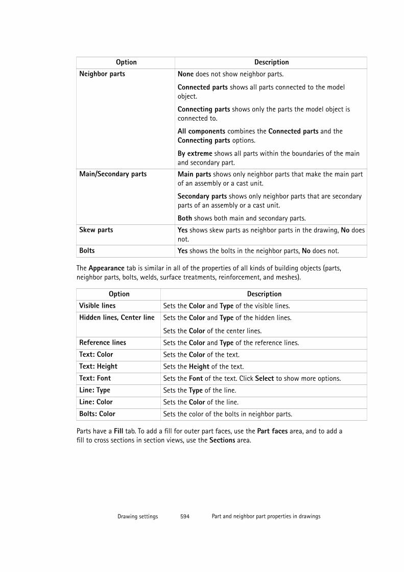
Option DescriptionNeighbor parts None does not show neighbor parts.
Connected parts shows all parts connected to the modelobject.
Connecting parts shows only the parts the model object isconnected to.
All components combines the Connected parts and theConnecting parts options.
By extreme shows all parts within the boundaries of the mainand secondary part.
Main/Secondary parts Main parts shows only neighbor parts that make the main partof an assembly or a cast unit.
Secondary parts shows only neighbor parts that are secondaryparts of an assembly or a cast unit.
Both shows both main and secondary parts.
Skew parts Yes shows skew parts as neighbor parts in the drawing, No doesnot.
Bolts Yes shows the bolts in the neighbor parts, No does not.
The Appearance tab is similar in all of the properties of all kinds of building objects (parts,neighbor parts, bolts, welds, surface treatments, reinforcement, and meshes).
Option DescriptionVisible lines Sets the Color and Type of the visible lines.
Hidden lines, Center line Sets the Color and Type of the hidden lines.
Sets the Color of the center lines.
Reference lines Sets the Color and Type of the reference lines.
Text: Color Sets the Color of the text.
Text: Height Sets the Height of the text.
Text: Font Sets the Font of the text. Click Select to show more options.
Line: Type Sets the Type of the line.
Line: Color Sets the Color of the line.
Bolts: Color Sets the color of the bolts in neighbor parts.
Parts have a Fill tab. To add a fill for outer part faces, use the Part faces area, and to add afill to cross sections in section views, use the Sections area.
Drawing settings 594 Part and neighbor part properties in drawings
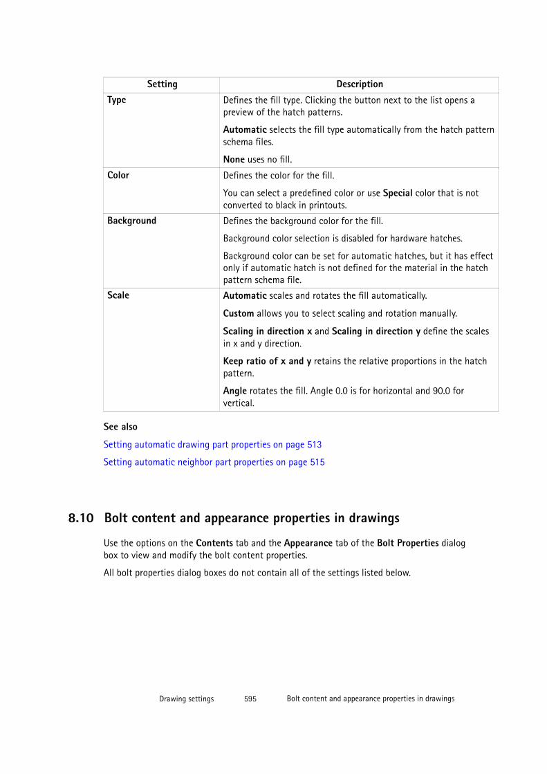
Setting DescriptionType Defines the fill type. Clicking the button next to the list opens a
preview of the hatch patterns.
Automatic selects the fill type automatically from the hatch patternschema files.
None uses no fill.
Color Defines the color for the fill.
You can select a predefined color or use Special color that is notconverted to black in printouts.
Background Defines the background color for the fill.
Background color selection is disabled for hardware hatches.
Background color can be set for automatic hatches, but it has effectonly if automatic hatch is not defined for the material in the hatchpattern schema file.
Scale Automatic scales and rotates the fill automatically.
Custom allows you to select scaling and rotation manually.
Scaling in direction x and Scaling in direction y define the scalesin x and y direction.
Keep ratio of x and y retains the relative proportions in the hatchpattern.
Angle rotates the fill. Angle 0.0 is for horizontal and 90.0 forvertical.
See also
Setting automatic drawing part properties on page 513
Setting automatic neighbor part properties on page 515
8.10 Bolt content and appearance properties in drawings
Use the options on the Contents tab and the Appearance tab of the Bolt Properties dialogbox to view and modify the bolt content properties.
All bolt properties dialog boxes do not contain all of the settings listed below.
Drawing settings 595 Bolt content and appearance properties in drawings
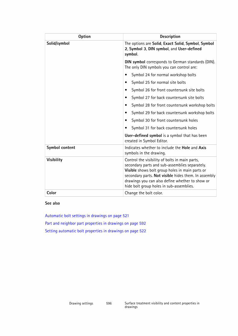
Option DescriptionSolid/symbol The options are Solid, Exact Solid, Symbol, Symbol
2, Symbol 3, DIN symbol, and User-definedsymbol.
DIN symbol corresponds to German standards (DIN).The only DIN symbols you can control are:
• Symbol 24 for normal workshop bolts
• Symbol 25 for normal site bolts
• Symbol 26 for front countersunk site bolts
• Symbol 27 for back countersunk site bolts
• Symbol 28 for front countersunk workshop bolts
• Symbol 29 for back countersunk workshop bolts
• Symbol 30 for front countersunk holes
• Symbol 31 for back countersunk holes
User-defined symbol is a symbol that has beencreated in Symbol Editor.
Symbol content Indicates whether to include the Hole and Axissymbols in the drawing.
Visibility Control the visibility of bolts in main parts,secondary parts and sub-assemblies separately.Visible shows bolt group holes in main parts orsecondary parts. Not visible hides them. In assemblydrawings you can also define whether to show orhide bolt group holes in sub-assemblies.
Color Change the bolt color.
See also
Automatic bolt settings in drawings on page 521
Part and neighbor part properties in drawings on page 592
Setting automatic bolt properties in drawings on page 522
Drawing settings 596 Surface treatment visibility and content properties indrawings
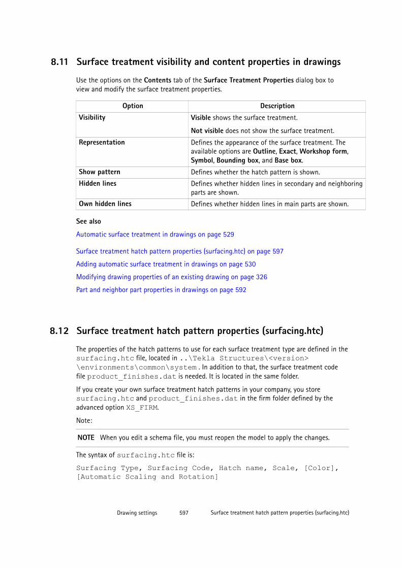
8.11 Surface treatment visibility and content properties in drawings
Use the options on the Contents tab of the Surface Treatment Properties dialog box toview and modify the surface treatment properties.
Option DescriptionVisibility Visible shows the surface treatment.
Not visible does not show the surface treatment.
Representation Defines the appearance of the surface treatment. Theavailable options are Outline, Exact, Workshop form,Symbol, Bounding box, and Base box.
Show pattern Defines whether the hatch pattern is shown.
Hidden lines Defines whether hidden lines in secondary and neighboringparts are shown.
Own hidden lines Defines whether hidden lines in main parts are shown.
See also
Automatic surface treatment in drawings on page 529
Surface treatment hatch pattern properties (surfacing.htc) on page 597
Adding automatic surface treatment in drawings on page 530
Modifying drawing properties of an existing drawing on page 326
Part and neighbor part properties in drawings on page 592
8.12 Surface treatment hatch pattern properties (surfacing.htc)
The properties of the hatch patterns to use for each surface treatment type are defined in thesurfacing.htc file, located in ..\Tekla Structures\<version>\environments\common\system . In addition to that, the surface treatment codefile product_finishes.dat is needed. It is located in the same folder.
If you create your own surface treatment hatch patterns in your company, you storesurfacing.htc and product_finishes.dat in the firm folder defined by theadvanced option XS_FIRM.
Note:
NOTE When you edit a schema file, you must reopen the model to apply the changes.
The syntax of surfacing.htc file is:
Surfacing Type, Surfacing Code, Hatch name, Scale, [Color],[Automatic Scaling and Rotation]
Drawing settings 597 Surface treatment hatch pattern properties (surfacing.htc)
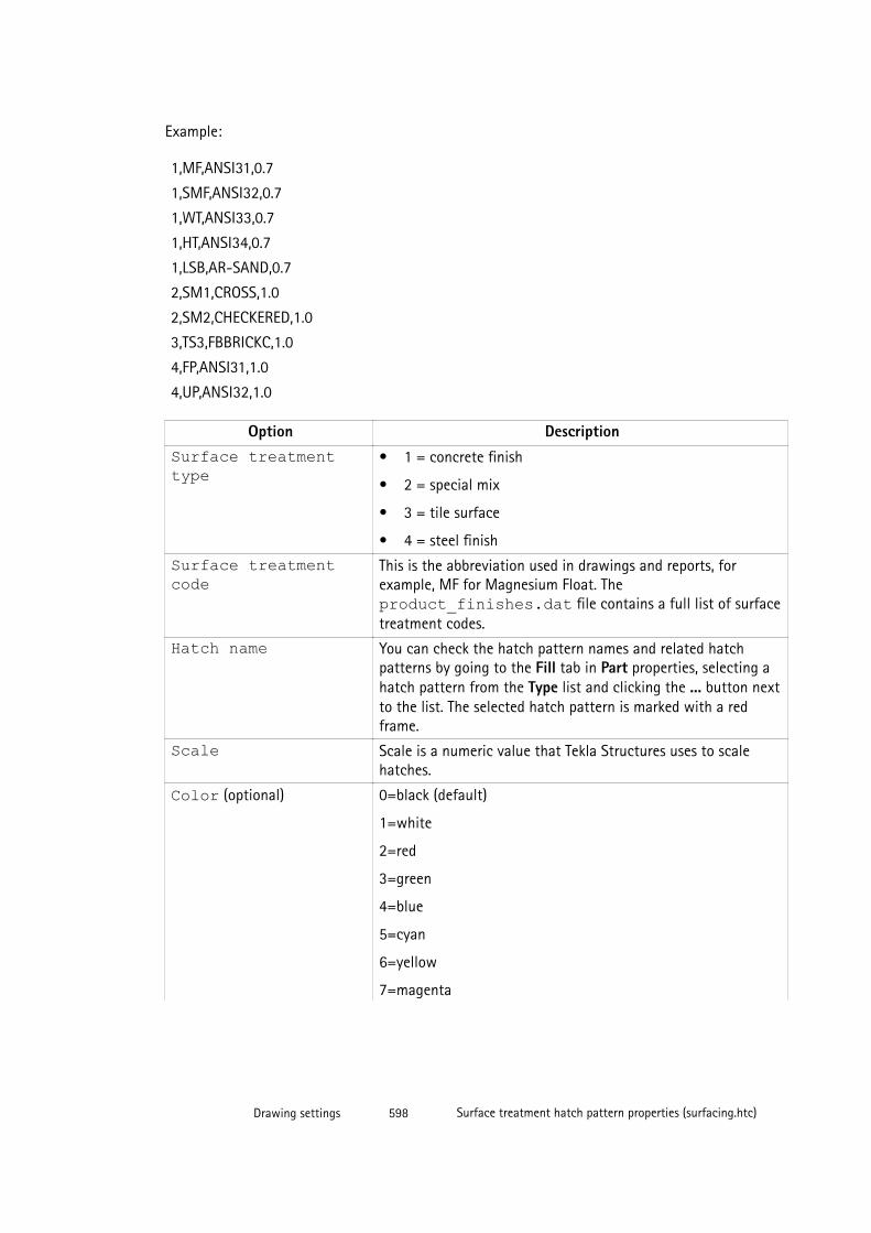
Example:
1,MF,ANSI31,0.7
1,SMF,ANSI32,0.7
1,WT,ANSI33,0.7
1,HT,ANSI34,0.7
1,LSB,AR-SAND,0.7
2,SM1,CROSS,1.0
2,SM2,CHECKERED,1.0
3,TS3,FBBRICKC,1.0
4,FP,ANSI31,1.0
4,UP,ANSI32,1.0
Option DescriptionSurface treatmenttype
• 1 = concrete finish
• 2 = special mix
• 3 = tile surface
• 4 = steel finish
Surface treatmentcode
This is the abbreviation used in drawings and reports, forexample, MF for Magnesium Float. Theproduct_finishes.dat file contains a full list of surfacetreatment codes.
Hatch name You can check the hatch pattern names and related hatchpatterns by going to the Fill tab in Part properties, selecting ahatch pattern from the Type list and clicking the ... button nextto the list. The selected hatch pattern is marked with a redframe.
Scale Scale is a numeric value that Tekla Structures uses to scalehatches.
Color (optional) 0=black (default)
1=white
2=red
3=green
4=blue
5=cyan
6=yellow
7=magenta
Drawing settings 598 Surface treatment hatch pattern properties (surfacing.htc)
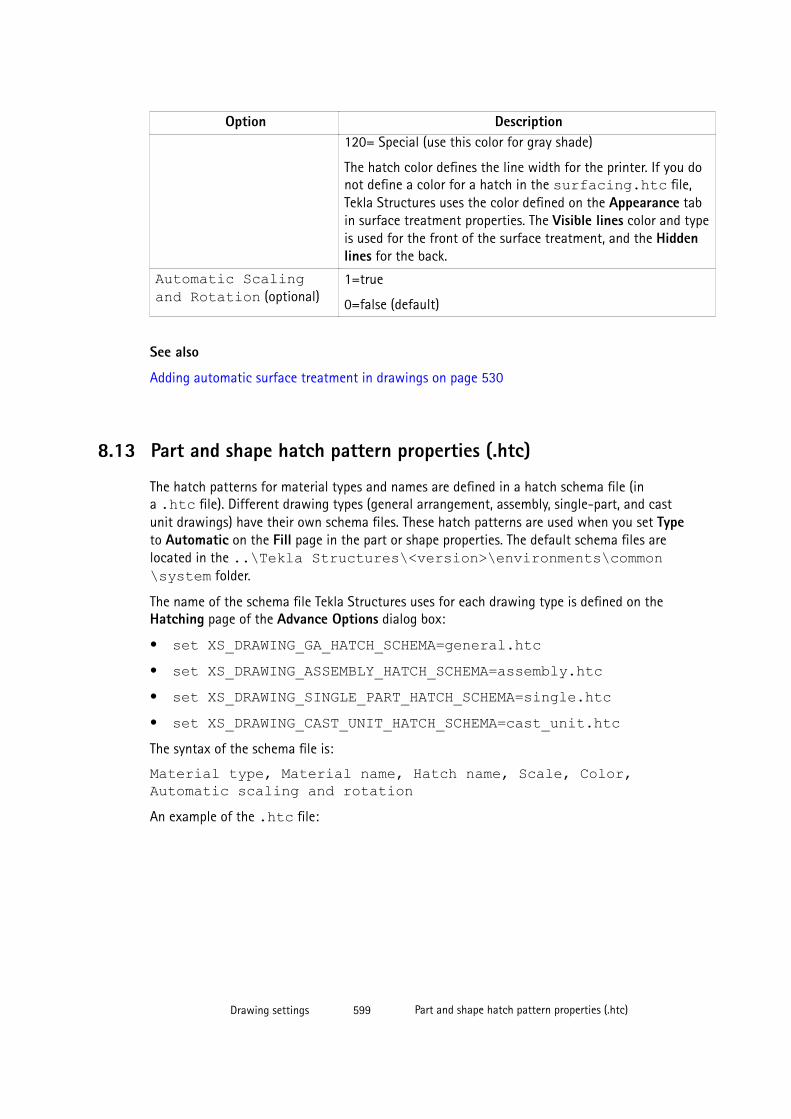
Option Description120= Special (use this color for gray shade)
The hatch color defines the line width for the printer. If you donot define a color for a hatch in the surfacing.htc file,Tekla Structures uses the color defined on the Appearance tabin surface treatment properties. The Visible lines color and typeis used for the front of the surface treatment, and the Hiddenlines for the back.
Automatic Scalingand Rotation (optional)
1=true
0=false (default)
See also
Adding automatic surface treatment in drawings on page 530
8.13 Part and shape hatch pattern properties (.htc)
The hatch patterns for material types and names are defined in a hatch schema file (ina .htc file). Different drawing types (general arrangement, assembly, single-part, and castunit drawings) have their own schema files. These hatch patterns are used when you set Typeto Automatic on the Fill page in the part or shape properties. The default schema files arelocated in the ..\Tekla Structures\<version>\environments\common\system folder.
The name of the schema file Tekla Structures uses for each drawing type is defined on theHatching page of the Advance Options dialog box:
• set XS_DRAWING_GA_HATCH_SCHEMA=general.htc• set XS_DRAWING_ASSEMBLY_HATCH_SCHEMA=assembly.htc• set XS_DRAWING_SINGLE_PART_HATCH_SCHEMA=single.htc• set XS_DRAWING_CAST_UNIT_HATCH_SCHEMA=cast_unit.htcThe syntax of the schema file is:
Material type, Material name, Hatch name, Scale, Color,Automatic scaling and rotationAn example of the .htc file:
Drawing settings 599 Part and shape hatch pattern properties (.htc)
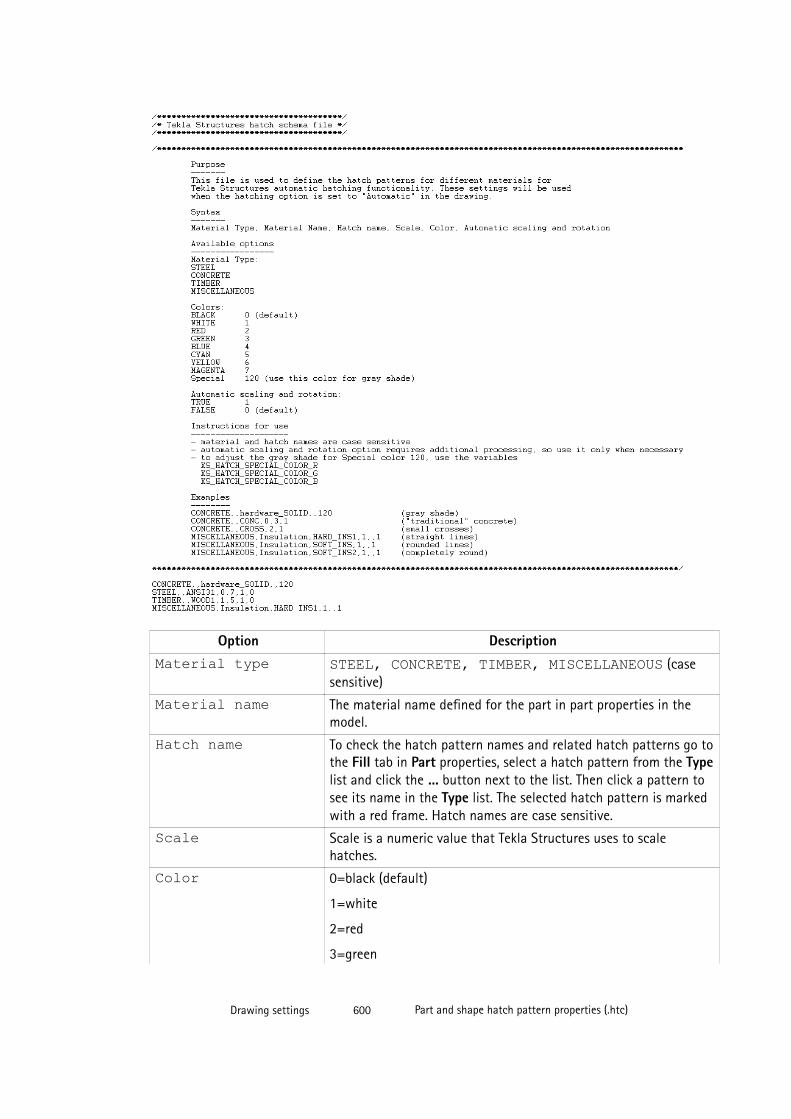
Option DescriptionMaterial type STEEL, CONCRETE, TIMBER, MISCELLANEOUS (case
sensitive)
Material name The material name defined for the part in part properties in themodel.
Hatch name To check the hatch pattern names and related hatch patterns go tothe Fill tab in Part properties, select a hatch pattern from the Typelist and click the ... button next to the list. Then click a pattern tosee its name in the Type list. The selected hatch pattern is markedwith a red frame. Hatch names are case sensitive.
Scale Scale is a numeric value that Tekla Structures uses to scalehatches.
Color 0=black (default)
1=white
2=red
3=green
Drawing settings 600 Part and shape hatch pattern properties (.htc)
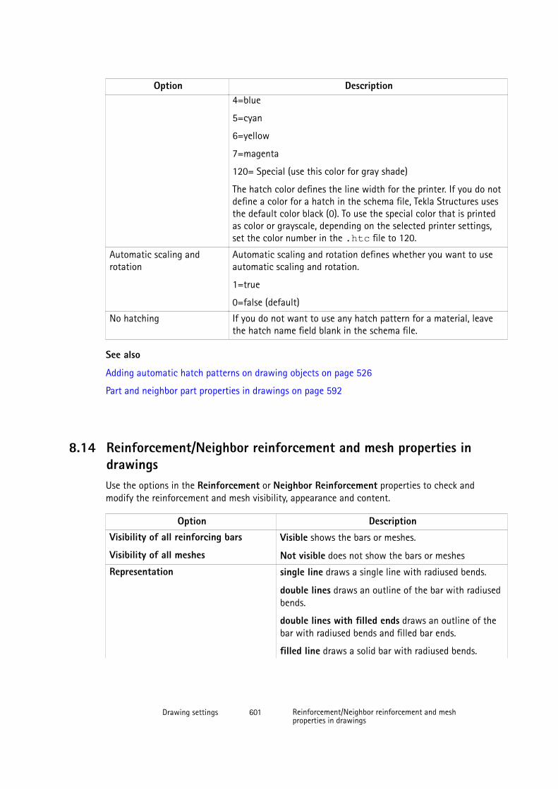
Option Description4=blue
5=cyan
6=yellow
7=magenta
120= Special (use this color for gray shade)
The hatch color defines the line width for the printer. If you do notdefine a color for a hatch in the schema file, Tekla Structures usesthe default color black (0). To use the special color that is printedas color or grayscale, depending on the selected printer settings,set the color number in the .htc file to 120.
Automatic scaling androtation
Automatic scaling and rotation defines whether you want to useautomatic scaling and rotation.
1=true
0=false (default)
No hatching If you do not want to use any hatch pattern for a material, leavethe hatch name field blank in the schema file.
See also
Adding automatic hatch patterns on drawing objects on page 526
Part and neighbor part properties in drawings on page 592
8.14 Reinforcement/Neighbor reinforcement and mesh properties indrawingsUse the options in the Reinforcement or Neighbor Reinforcement properties to check andmodify the reinforcement and mesh visibility, appearance and content.
Option DescriptionVisibility of all reinforcing bars
Visibility of all meshes
Visible shows the bars or meshes.
Not visible does not show the bars or meshes
Representation single line draws a single line with radiused bends.
double lines draws an outline of the bar with radiusedbends.
double lines with filled ends draws an outline of thebar with radiused bends and filled bar ends.
filled line draws a solid bar with radiused bends.
Drawing settings 601 Reinforcement/Neighbor reinforcement and meshproperties in drawings

Option Descriptionstick draws a single line without radiused bends.
outline shows the shape of the mesh using an outlinerectangle or polygon, and a diagonal line. Applies onlyto reinforcement meshes.
Visibility of reinforcing bars in group
Visibility of longitudinal wires
Visibility of crossing bars
all shows all bars in a group or mesh.
first bar shows only the first bar in the group or mesh.
last bar shows only the last bar in the group or mesh.
first and last bar shows the first and last bar in thegroup or mesh.
bar in the middle of group shows one bar in themiddle of the group or mesh.
two bars in the middle of group shows two bars inthe middle of the group or mesh.
customized indicates that you have specified thelocation of the only visible reinforcing bar. Applies onlyto bar groups and meshes.
Hide lines behind parts Hides the lines behind the part. This is useful, forexample, with lifting anchors where the reinforcing baris partly outside the part.
Hide lines behind other rebars Hides the lines behind other reinforcement bar lines.
Symbol at straight end
Applies only to reinforcing bars.
Symbol at hooked end
Applies only to reinforcing bars.
Mesh symbol Defines the mesh symbol to be used. The mesh symbolappears in the middle of the diagonal line.
Symbol 1
Drawing settings 602 Reinforcement/Neighbor reinforcement and meshproperties in drawings
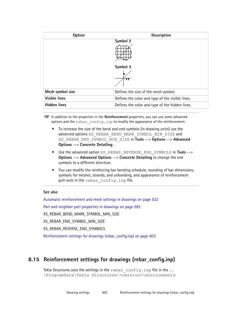
Option DescriptionSymbol 2
Symbol 3
Mesh symbol size Defines the size of the mesh symbol.
Visible lines Defines the color and type of the visible lines.
Hidden lines Defines the color and type of the hidden lines.
TIP In addition to the properties in the Reinforcement properties, you can use some advancedoptions and the rebar_config.inp to modify the appearance of the reinforcement:
• To increase the size of the bend and end symbols (in drawing units) use theadvanced options XS_REBAR_BEND_MARK_SYMBOL_MIN_SIZE and XS_REBAR_END_SYMBOL_MIN_SIZE in Tools --> Options --> AdvancedOptions --> Concrete Detailing .
• Use the advanced option XS_REBAR_REVERSE_END_SYMBOLS in Tools -->Options --> Advanced Options --> Concrete Detailing to change the endsymbols to a different direction.
• You can modify the reinforcing bar bending schedule, rounding of bar dimensions,symbols for meshes, strands, and unbonding, and appearance of reinforcementpull-outs in the rebar_config.inp file.
See also
Automatic reinforcement and mesh settings in drawings on page 532
Part and neighbor part properties in drawings on page 592
XS_REBAR_BEND_MARK_SYMBOL_MIN_SIZE
XS_REBAR_END_SYMBOL_MIN_SIZE
XS_REBAR_REVERSE_END_SYMBOLS
Reinforcement settings for drawings (rebar_config.inp) on page 603
8.15 Reinforcement settings for drawings (rebar_config.inp)
Tekla Structures uses the settings in the rebar_config.inp file in the ..\ProgramData\Tekla Structures\<version>\environments
Drawing settings 603 Reinforcement settings for drawings (rebar_config.inp)
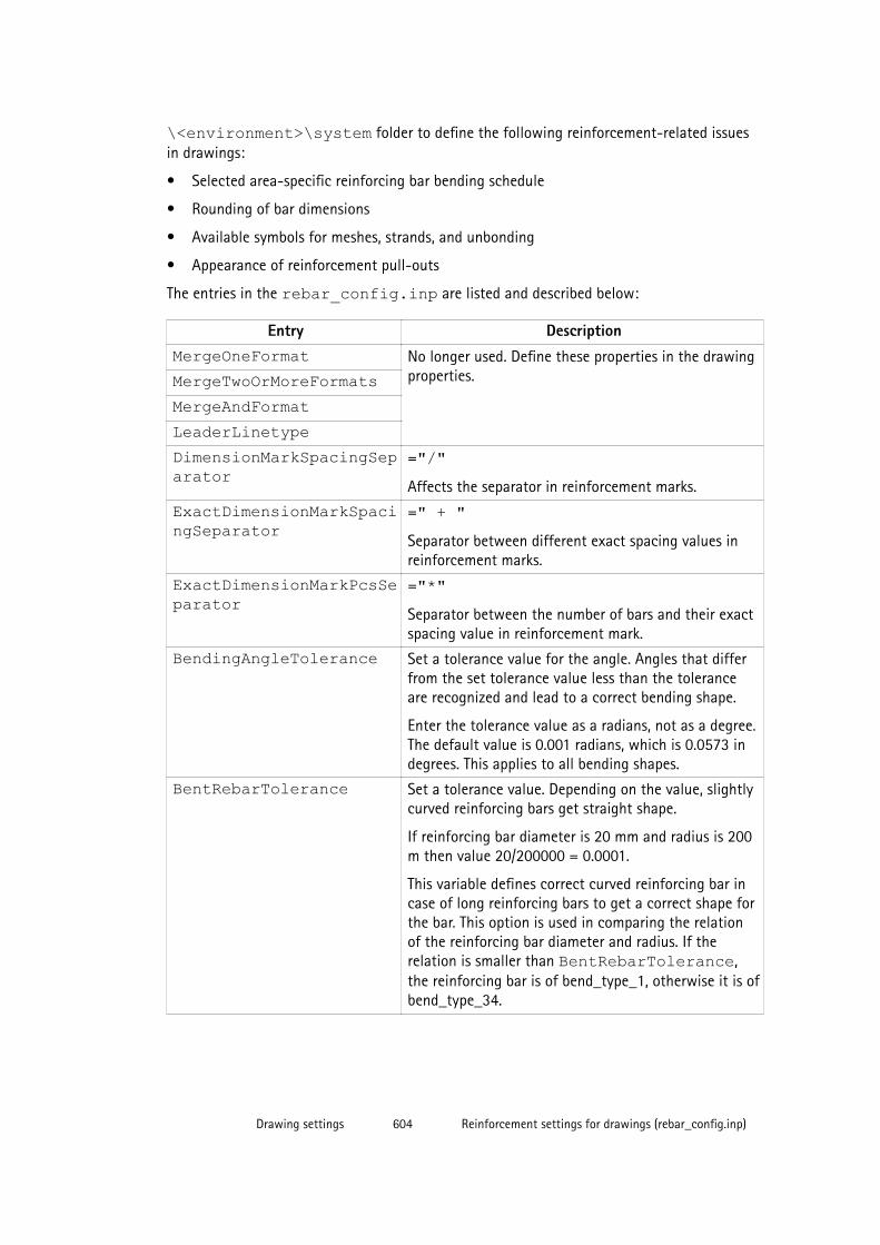
\<environment>\system folder to define the following reinforcement-related issuesin drawings:
• Selected area-specific reinforcing bar bending schedule
• Rounding of bar dimensions
• Available symbols for meshes, strands, and unbonding
• Appearance of reinforcement pull-outs
The entries in the rebar_config.inp are listed and described below:
Entry DescriptionMergeOneFormat No longer used. Define these properties in the drawing
properties.MergeTwoOrMoreFormatsMergeAndFormatLeaderLinetypeDimensionMarkSpacingSeparator
="/"Affects the separator in reinforcement marks.
ExactDimensionMarkSpacingSeparator
=" + "Separator between different exact spacing values inreinforcement marks.
ExactDimensionMarkPcsSeparator
="*"Separator between the number of bars and their exactspacing value in reinforcement mark.
BendingAngleTolerance Set a tolerance value for the angle. Angles that differfrom the set tolerance value less than the toleranceare recognized and lead to a correct bending shape.
Enter the tolerance value as a radians, not as a degree.The default value is 0.001 radians, which is 0.0573 indegrees. This applies to all bending shapes.
BentRebarTolerance Set a tolerance value. Depending on the value, slightlycurved reinforcing bars get straight shape.
If reinforcing bar diameter is 20 mm and radius is 200m then value 20/200000 = 0.0001.
This variable defines correct curved reinforcing bar incase of long reinforcing bars to get a correct shape forthe bar. This option is used in comparing the relationof the reinforcing bar diameter and radius. If therelation is smaller than BentRebarTolerance,the reinforcing bar is of bend_type_1, otherwise it is ofbend_type_34.
Drawing settings 604 Reinforcement settings for drawings (rebar_config.inp)
Entry DescriptionPullOutBendingRadiusAsMultiplier
Set to 1 to show the pullout bending radii usingmultiplier instead of mm.
GroupBarMark No longer in use.
MarkingDimAttributes No longer in use.
ScheduleCountry Defines which bending schedule is used. Affectsbending shapes in templates and reports. The availableschedules are FIN, SWE, UK, US.
When you number the model, the bending shape forthe bar is given according to this information. Forexample, in the Default environment, the bendingshapes are letters A, B, C, and so on.
ScheduleDimensionRoundingDirectionScheduleTotalLengthRoundingDirection
Options:
• "UP": rounds bar dimensions up
• "DOWN": rounds bar dimensions down
• "NEAREST": rounds bar dimensions either up ordown
ScheduleDimensionRoundingAccuracy
Sets the rounding accuracy for bar dimensions. Defaultis 1 mm.
Tekla Structures rounds individual bar dimensions up ordown according to the option you select for ScheduleDimensionRoundingDirection.
ScheduleTotalLengthRoundingAccuracy
Sets the rounding accuracy for the total bar length.Default is 10 mm.
Tekla Structures rounds individual bar dimensions up ordown according to the option you select for ScheduleTotalLengthRoundingDirection.
BentSymbolFile Points to the symbol file that contains the availablereinforcing bar bent symbols. By default, points to the
Drawing settings 605 Reinforcement settings for drawings (rebar_config.inp)
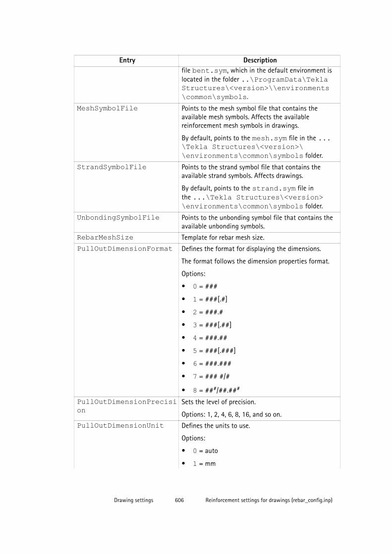
Entry Descriptionfile bent.sym, which in the default environment islocated in the folder ..\ProgramData\TeklaStructures\<version>\\environments\common\symbols.
MeshSymbolFile Points to the mesh symbol file that contains theavailable mesh symbols. Affects the availablereinforcement mesh symbols in drawings.
By default, points to the mesh.sym file in the ...\Tekla Structures\<version>\\environments\common\symbols folder.
StrandSymbolFile Points to the strand symbol file that contains theavailable strand symbols. Affects drawings.
By default, points to the strand.sym file inthe ...\Tekla Structures\<version>\environments\common\symbols folder.
UnbondingSymbolFile Points to the unbonding symbol file that contains theavailable unbonding symbols.
RebarMeshSize Template for rebar mesh size.
PullOutDimensionFormat Defines the format for displaying the dimensions.
The format follows the dimension properties format.
Options:
• 0 = ###
• 1 = ###[.#]
• 2 = ###.#
• 3 = ###[.##]
• 4 = ###.##
• 5 = ###[.###]
• 6 = ###.###
• 7 = ### #/#
• 8 = ###/##.###
PullOutDimensionPrecision
Sets the level of precision.
Options: 1, 2, 4, 6, 8, 16, and so on.
PullOutDimensionUnit Defines the units to use.
Options:
• 0 = auto
• 1 = mm
Drawing settings 606 Reinforcement settings for drawings (rebar_config.inp)
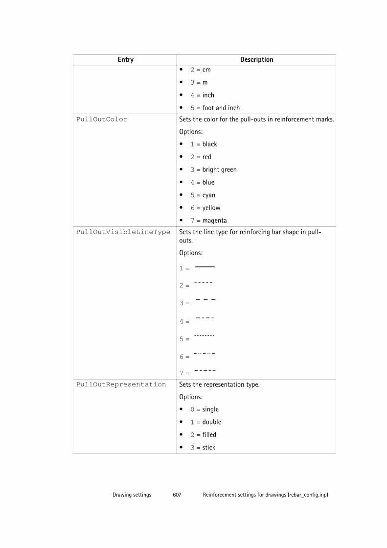
Entry Description• 2 = cm
• 3 = m
• 4 = inch
• 5 = foot and inch
PullOutColor Sets the color for the pull-outs in reinforcement marks.
Options:
• 1 = black
• 2 = red
• 3 = bright green
• 4 = blue
• 5 = cyan
• 6 = yellow
• 7 = magenta
PullOutVisibleLineType Sets the line type for reinforcing bar shape in pull-outs.
Options:
1 =
2 =
3 =
4 =
5 =
6 =
7 =
PullOutRepresentation Sets the representation type.
Options:
• 0 = single
• 1 = double
• 2 = filled
• 3 = stick
Drawing settings 607 Reinforcement settings for drawings (rebar_config.inp)
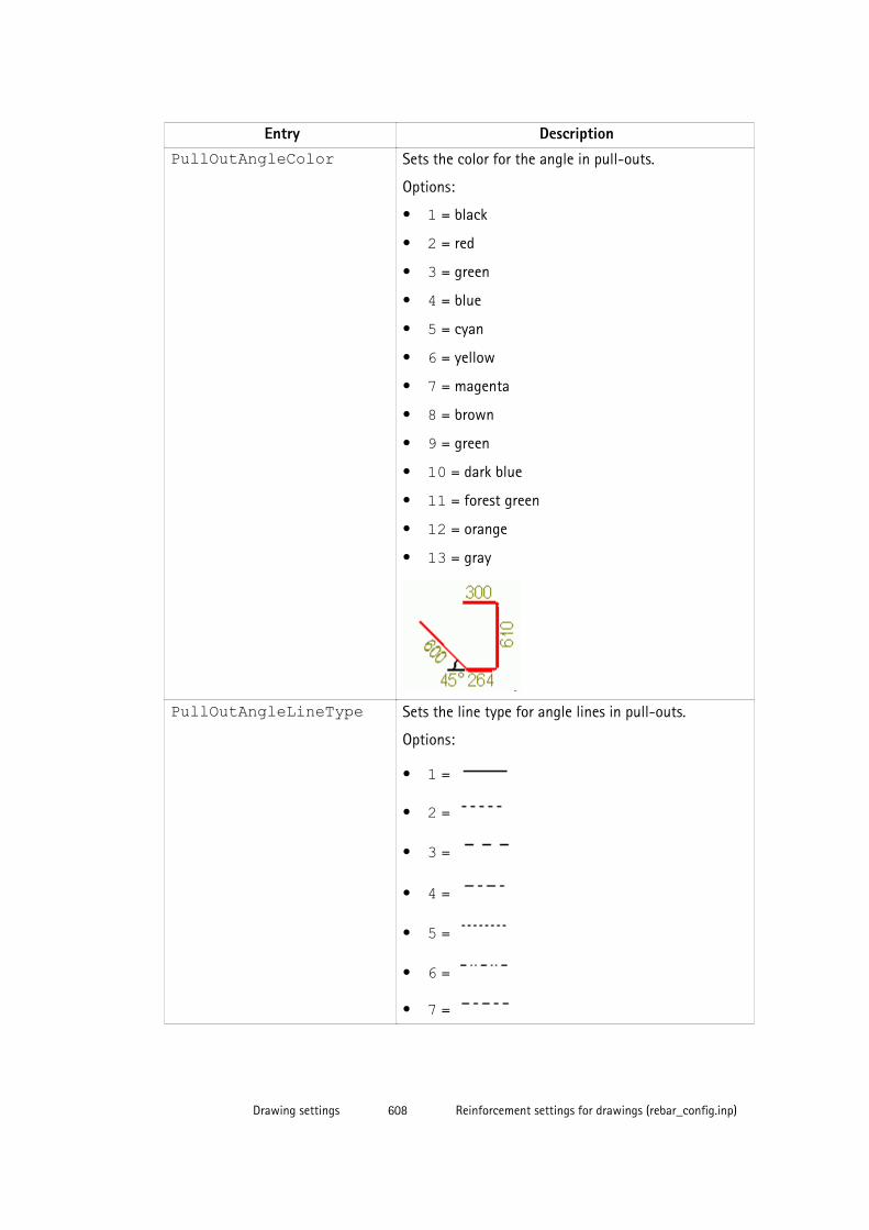
Entry DescriptionPullOutAngleColor Sets the color for the angle in pull-outs.
Options:
• 1 = black
• 2 = red
• 3 = green
• 4 = blue
• 5 = cyan
• 6 = yellow
• 7 = magenta
• 8 = brown
• 9 = green
• 10 = dark blue
• 11 = forest green
• 12 = orange
• 13 = gray
PullOutAngleLineType Sets the line type for angle lines in pull-outs.
Options:
• 1 =
• 2 =
• 3 =
• 4 =
• 5 =
• 6 =
• 7 =
Drawing settings 608 Reinforcement settings for drawings (rebar_config.inp)
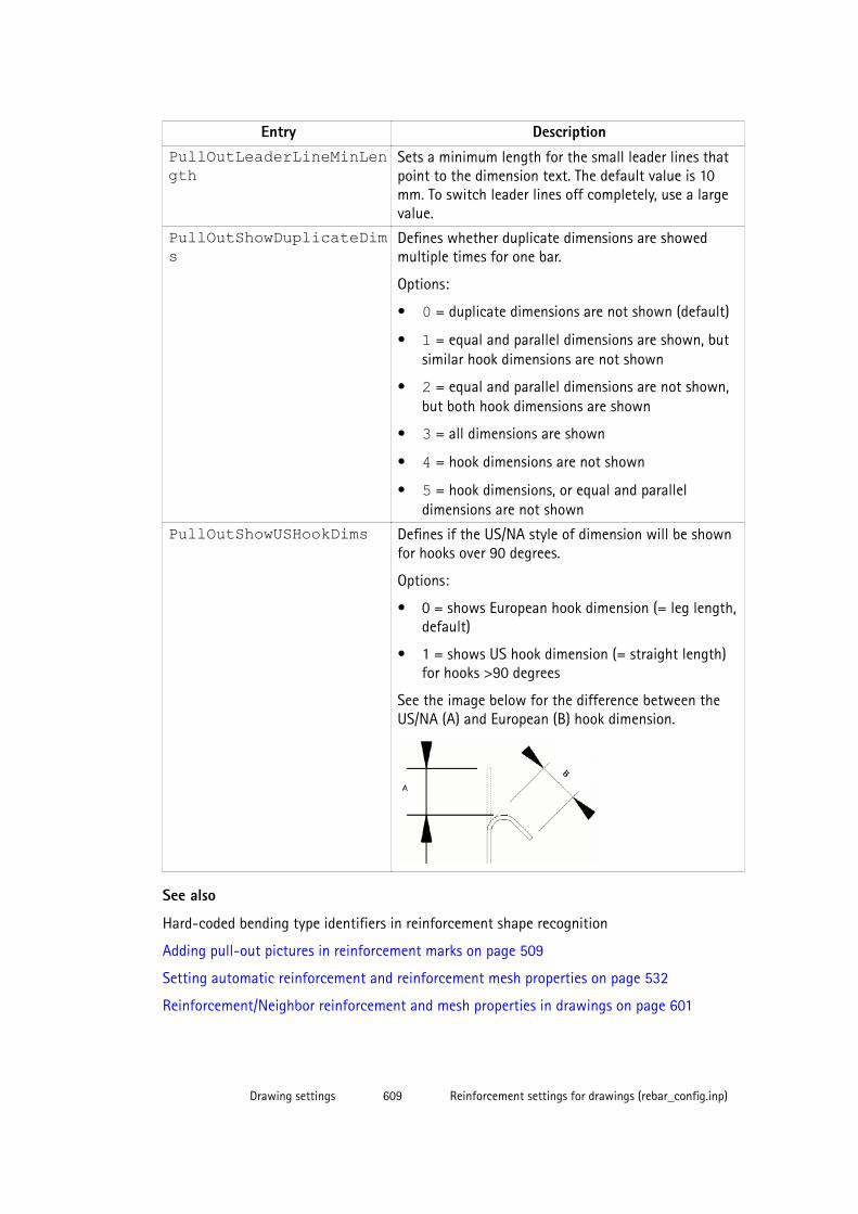
Entry DescriptionPullOutLeaderLineMinLength
Sets a minimum length for the small leader lines thatpoint to the dimension text. The default value is 10mm. To switch leader lines off completely, use a largevalue.
PullOutShowDuplicateDims
Defines whether duplicate dimensions are showedmultiple times for one bar.
Options:
• 0 = duplicate dimensions are not shown (default)
• 1 = equal and parallel dimensions are shown, butsimilar hook dimensions are not shown
• 2 = equal and parallel dimensions are not shown,but both hook dimensions are shown
• 3 = all dimensions are shown
• 4 = hook dimensions are not shown
• 5 = hook dimensions, or equal and paralleldimensions are not shown
PullOutShowUSHookDims Defines if the US/NA style of dimension will be shownfor hooks over 90 degrees.
Options:
• 0 = shows European hook dimension (= leg length,default)
• 1 = shows US hook dimension (= straight length)for hooks >90 degrees
See the image below for the difference between theUS/NA (A) and European (B) hook dimension.
See also
Hard-coded bending type identifiers in reinforcement shape recognition
Adding pull-out pictures in reinforcement marks on page 509
Setting automatic reinforcement and reinforcement mesh properties on page 532
Reinforcement/Neighbor reinforcement and mesh properties in drawings on page 601
Drawing settings 609 Reinforcement settings for drawings (rebar_config.inp)

8.16 Pour object and pour break properties in drawingsUse the options in Pour Object Properties and Pour Break Properties dialog boxes ondrawing level (general arrangement drawings only ) and on object level, and in Pour objectand Pour break panels on view level to control the visibility of the pour objects and pourbreaks in drawings.
Pour object properties
Option DescriptionContent tab - Hidden linesHidden lines on/off Click on to display pour object hidden lines.
Own hidden lines on/off Click on to display own hidden lines.
Content tab - Addional marksEdge chamfers on/off Select on to display edge chamfers.
Appearance tab - Visible linesColor Select the color of the visible pour object
lines.
Type Select the type of the visible pour objectlines.
Appearance tab - Hidden linesColor Select the color of the hidden pour object
lines.
Type Select the type of the hidden pour objectlines.
Fill tab
To add a fill for outer pour faces, use the Pour faces area, and to add a fill for cross sectionsin section views, use the Sections area.
Type Defines the fill type. Clicking the button nextto the list opens a preview of the hatchpatterns.
Automatic selects the fill type automaticallyfrom the hatch pattern schema files.
None uses no fill.
Color Defines the color for the fill.
You can select a predefined color or useSpecial color that is not converted to blackin printouts.
Drawing settings 610 Pour object and pour break properties in drawings
Option DescriptionBackground Defines the background color for the fill.
Background color selection is disabled forhardware hatches.
Background color can be set for automatichatches, but it has effect only if automatichatch is not defined for the material in thehatch pattern schema file.
Scale Automatic scales and rotates the fillautomatically.
Custom allows you to select scaling androtation manually.
Scaling in direction x and Scaling indirection y define the scales in x and ydirection.
Keep ratio of x and y retains the relativeproportions in the hatch pattern.
Angle rotates the fill. For example, Angle 0.0is for horizontal and Angle 90.0 for vertical.
Pour break properties
Option DescriptionContent tab - Hidden linesVisibility Defines if the pour breaks are visible (Visible)
or not (Not visible).
Hidden lines on/off Click on to display pour break hidden lines.
Appearance tab - Visible linesColor Select the color of the visible pour break
lines.
Type Select the type of the visible pour breaklines.
Appearance tab - Hidden linesColor Select the color of the hidden pour break
lines.
Type Select the type of the hidden pour breaklines.
See also
Pours in drawings on page 236
Showing pour objects, pour marks and pour breaks in drawings on page 238
Drawing settings 611 Pour object and pour break properties in drawings
8.17 Placement properties for annotation objects
Use the settings in the Placing dialog boxes for annotation objects and dimensions to controlhow the annotation objects are placed in a drawing.
Option DescriptionSearch margin Defines the distance within which Tekla Structures searches
for a space to place a dimension, mark, weld mark or anotherannotation object.
Minimal distance Defines the minimum distance of the mark, weld mark,dimension or another annotation object from the part.
Quarter For marks and manually added annotation objects.
Defines the areas Tekla Structures searches for a space toplace the mark or annotation object.
Weld placement depends on the welding direction. Weldscan only be placed in certain sectors, so the Quarter optionsare not available. This option is available for manually addedwelds in the final drawing.
Placing free allows Tekla Structures to search for the first suitablelocation for the mark, dimension, weld or anotherannotation object. fixed allows you to place the mark,dimension, weld or another annotation object in anylocation.
When you use the option fixed, the annotation object stayswhere it is even though you update the drawing, whereaswith free, Tekla Structures tries to find the optimal place forthe annotation object.
Direction Available only for manual dimensions.
Defines the side on which Tekla Structures places dimensions(relative to the object being dimensioned). This settingaffects the Placing - free setting.
See also
Object protection and placement settings in drawings on page 357
8.18 Welding propertiesYou can select which model welds are visible in drawings and drawing views, and set theweld color and line type.
Drawing settings 612 Placement properties for annotation objects
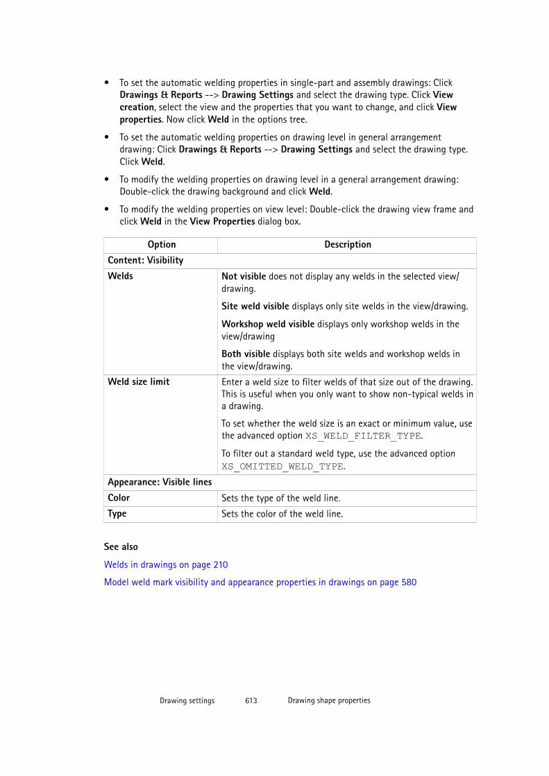
• To set the automatic welding properties in single-part and assembly drawings: ClickDrawings & Reports --> Drawing Settings and select the drawing type. Click Viewcreation, select the view and the properties that you want to change, and click Viewproperties. Now click Weld in the options tree.
• To set the automatic welding properties on drawing level in general arrangementdrawing: Click Drawings & Reports --> Drawing Settings and select the drawing type.Click Weld.
• To modify the welding properties on drawing level in a general arrangement drawing:Double-click the drawing background and click Weld.
• To modify the welding properties on view level: Double-click the drawing view frame andclick Weld in the View Properties dialog box.
Option DescriptionContent: VisibilityWelds Not visible does not display any welds in the selected view/
drawing.
Site weld visible displays only site welds in the view/drawing.
Workshop weld visible displays only workshop welds in theview/drawing
Both visible displays both site welds and workshop welds inthe view/drawing.
Weld size limit Enter a weld size to filter welds of that size out of the drawing.This is useful when you only want to show non-typical welds ina drawing.
To set whether the weld size is an exact or minimum value, usethe advanced option XS_WELD_FILTER_TYPE.
To filter out a standard weld type, use the advanced option XS_OMITTED_WELD_TYPE.
Appearance: Visible linesColor Sets the type of the weld line.
Type Sets the color of the weld line.
See also
Welds in drawings on page 210
Model weld mark visibility and appearance properties in drawings on page 580
Drawing settings 613 Drawing shape properties
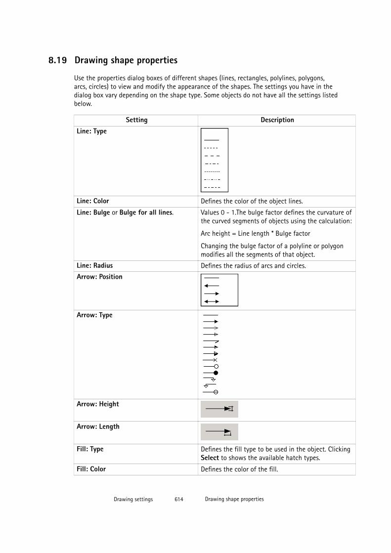
8.19 Drawing shape properties
Use the properties dialog boxes of different shapes (lines, rectangles, polylines, polygons,arcs, circles) to view and modify the appearance of the shapes. The settings you have in thedialog box vary depending on the shape type. Some objects do not have all the settings listedbelow.
Setting DescriptionLine: Type
Line: Color Defines the color of the object lines.
Line: Bulge or Bulge for all lines. Values 0 - 1.The bulge factor defines the curvature ofthe curved segments of objects using the calculation:
Arc height = Line length * Bulge factor
Changing the bulge factor of a polyline or polygonmodifies all the segments of that object.
Line: Radius Defines the radius of arcs and circles.
Arrow: Position
Arrow: Type
Arrow: Height
Arrow: Length
Fill: Type Defines the fill type to be used in the object. ClickingSelect to shows the available hatch types.
Fill: Color Defines the color of the fill.
Drawing settings 614 Drawing shape properties
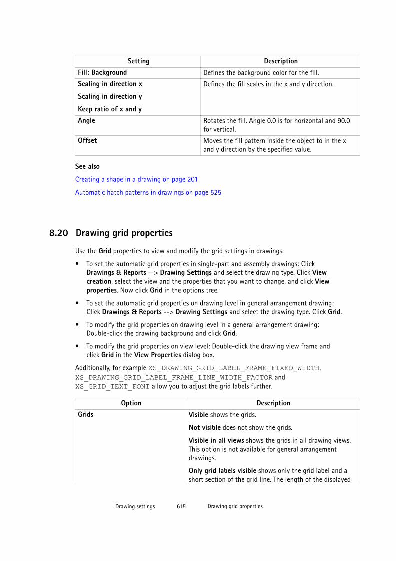
Setting DescriptionFill: Background Defines the background color for the fill.
Scaling in direction x
Scaling in direction y
Keep ratio of x and y
Defines the fill scales in the x and y direction.
Angle Rotates the fill. Angle 0.0 is for horizontal and 90.0for vertical.
Offset Moves the fill pattern inside the object to in the xand y direction by the specified value.
See also
Creating a shape in a drawing on page 201
Automatic hatch patterns in drawings on page 525
8.20 Drawing grid properties
Use the Grid properties to view and modify the grid settings in drawings.
• To set the automatic grid properties in single-part and assembly drawings: ClickDrawings & Reports --> Drawing Settings and select the drawing type. Click Viewcreation, select the view and the properties that you want to change, and click Viewproperties. Now click Grid in the options tree.
• To set the automatic grid properties on drawing level in general arrangement drawing:Click Drawings & Reports --> Drawing Settings and select the drawing type. Click Grid.
• To modify the grid properties on drawing level in a general arrangement drawing:Double-click the drawing background and click Grid.
• To modify the grid properties on view level: Double-click the drawing view frame andclick Grid in the View Properties dialog box.
Additionally, for example XS_DRAWING_GRID_LABEL_FRAME_FIXED_WIDTH, XS_DRAWING_GRID_LABEL_FRAME_LINE_WIDTH_FACTOR and XS_GRID_TEXT_FONT allow you to adjust the grid labels further.
Option DescriptionGrids Visible shows the grids.
Not visible does not show the grids.
Visible in all views shows the grids in all drawing views.This option is not available for general arrangementdrawings.
Only grid labels visible shows only the grid label and ashort section of the grid line. The length of the displayed
Drawing settings 615 Drawing grid properties
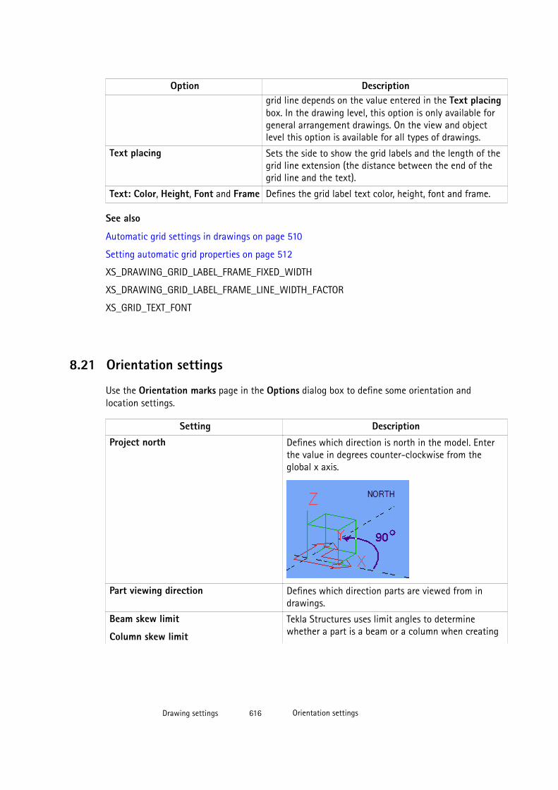
Option Descriptiongrid line depends on the value entered in the Text placingbox. In the drawing level, this option is only available forgeneral arrangement drawings. On the view and objectlevel this option is available for all types of drawings.
Text placing Sets the side to show the grid labels and the length of thegrid line extension (the distance between the end of thegrid line and the text).
Text: Color, Height, Font and Frame Defines the grid label text color, height, font and frame.
See also
Automatic grid settings in drawings on page 510
Setting automatic grid properties on page 512
XS_DRAWING_GRID_LABEL_FRAME_FIXED_WIDTH
XS_DRAWING_GRID_LABEL_FRAME_LINE_WIDTH_FACTOR
XS_GRID_TEXT_FONT
8.21 Orientation settings
Use the Orientation marks page in the Options dialog box to define some orientation andlocation settings.
Setting DescriptionProject north Defines which direction is north in the model. Enter
the value in degrees counter-clockwise from theglobal x axis.
Part viewing direction Defines which direction parts are viewed from indrawings.
Beam skew limit
Column skew limit
Tekla Structures uses limit angles to determinewhether a part is a beam or a column when creating
Drawing settings 616 Orientation settings
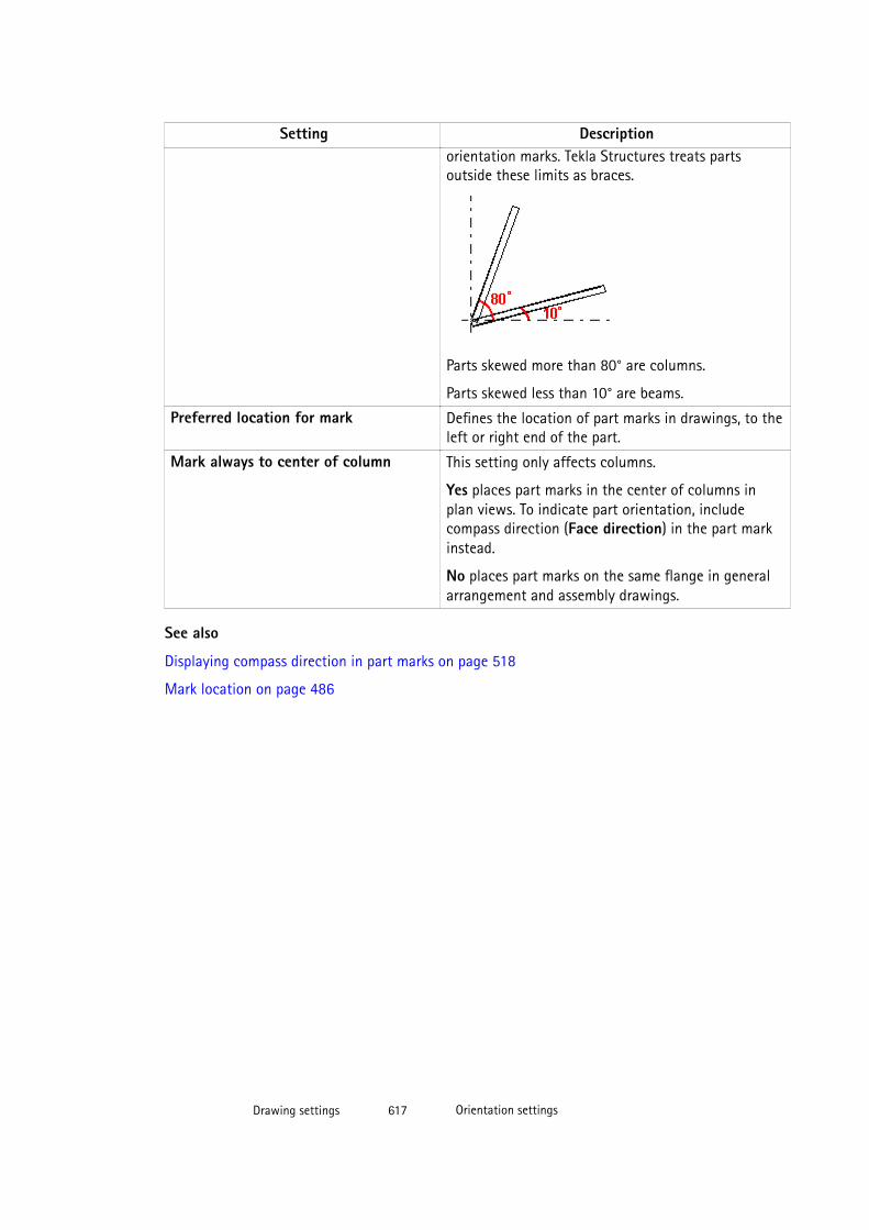
Setting Descriptionorientation marks. Tekla Structures treats partsoutside these limits as braces.
Parts skewed more than 80° are columns.
Parts skewed less than 10° are beams.
Preferred location for mark Defines the location of part marks in drawings, to theleft or right end of the part.
Mark always to center of column This setting only affects columns.
Yes places part marks in the center of columns inplan views. To indicate part orientation, includecompass direction (Face direction) in the part markinstead.
No places part marks on the same flange in generalarrangement and assembly drawings.
See also
Displaying compass direction in part marks on page 518
Mark location on page 486
Drawing settings 617 Orientation settings
9 Disclaimer
© 2015 Tekla Corporation and its licensors. All rights reserved.
This Software Manual has been developed for use with the referenced Software. Use of theSoftware, and use of this Software Manual are governed by a License Agreement. Amongother provisions, the License Agreement sets certain warranties for the Software and thisManual, disclaims other warranties, limits recoverable damages, defines permitted uses of theSoftware, and determines whether you are an authorized user of the Software. Allinformation set forth in this manual is provided with the warranty set forth in the LicenseAgreement. Please refer to the License Agreement for important obligations and applicablelimitations and restrictions on your rights. Tekla does not guarantee that the text is free oftechnical inaccuracies or typographical errors. Tekla reserves the right to make changes andadditions to this manual due to changes in the software or otherwise.
In addition, this Software Manual is protected by copyright law and by international treaties.Unauthorized reproduction, display, modification, or distribution of this Manual, or anyportion of it, may result in severe civil and criminal penalties, and will be prosecuted to thefull extent permitted by law.
Tekla, Tekla Structures, Tekla BIMsight, BIMsight, Tedds, Solve, Fastrak and Orion are eitherregistered trademarks or trademarks of Tekla Corporation in the European Union, the UnitedStates, and/or other countries. More about Tekla trademarks: http://www.tekla.com/tekla-trademarks. Trimble is a registered trademark or trademark of Trimble Navigation Limited inthe European Union, in the United States and/or other countries. More about Trimbletrademarks: http://www.trimble.com/trademarks.aspx. Other product and company namesmentioned in this Manual are or may be trademarks of their respective owners. By referringto a third-party product or brand, Tekla does not intend to suggest an affiliation with orendorsement by such third party and disclaims any such affiliation or endorsement, exceptwhere otherwise expressly stated.
Portions of this software:
D-Cubed 2D DCM © 2010 Siemens Industry Software Limited. All rights reserved.
EPM toolkit © 1995-2004 EPM Technology a.s., Oslo, Norway. All rights reserved.
Open CASCADE Technology © 2001-2014 Open CASCADE SA. All rights reserved.
FLY SDK - CAD SDK © 2012 VisualIntegrity™. All rights reserved.
Teigha © 2003-2014 Open Design Alliance. All rights reserved.
Disclaimer 618 Orientation settings

PolyBoolean C++ Library © 2001-2012 Complex A5 Co. Ltd. All rights reserved.
FlexNet Copyright © 2014 Flexera Software LLC. All Rights Reserved.
This product contains proprietary and confidential technology, information and creativeworks owned by Flexera Software LLC and its licensors, if any. Any use, copying, publication,distribution, display, modification, or transmission of such technology in whole or in part inany form or by any means without the prior express written permission of Flexera SoftwareLLC is strictly prohibited. Except where expressly provided by Flexera Software LLC in writing,possession of this technology shall not be construed to confer any license or rights under anyFlexera Software LLC intellectual property rights, whether by estoppel, implication, orotherwise.
To see the third party licenses, go to Tekla Structures, click Help --> About and click theThird party licenses button.
The elements of the software described in this Manual are protected by several patents andpossibly pending patent applications in the European Union and/or other countries. For moreinformation go to page http://www.tekla.com/tekla-patents.
Disclaimer 619 Orientation settings

Disclaimer 620 Orientation settings
Index
.
.rtf fileadding a link.............................................................195
22D.......................................................................................... 18
33D.......................................................................................... 18
drawing views...................................................119,551isometric drawings....................................................32rotation of views..................................................... 551
3Ddrawing views.......................................................... 126
3D views...............................................................................32
AA1........................................................................................ 339A2................................................................................315,339A3........................................................................315,339,345
printing.......................................................................301A4........................................................................315,339,345
printing.......................................................................301absolute dimensions...................................................... 556
appearance................................................................455orientation................................................................ 455zero at start point...................................................455
addingassociative notes..................................................... 183bolt marks..................................................................181closing dimensions..................................................176connection marks....................................................181dimension lines........................................................ 161dimension points.....................................................177dimension points in a nchor bolt plans............ 172
dimension tags.........................................................154drawing views.......................................................... 120dual dimensions.......................................................158foldmarks................................................................... 310frames.........................................................................310hyperlinks.................................................................. 198level marks................................................................ 182links to DWG/DXF files...........................................199links to other drawings..........................................197links to text files......................................................195manual dimensions.................................................146part marks................................................................. 181predefined reinforcement dimensions.............. 160reinforcement marks.............................................. 181revision marks.......................................................... 200single-part views in assembly drawings...........132surface treatment marks.......................................181symbols...................................................................... 246symbols in marks.....................................................505texts............................................................................ 193weld marks................................................................223
AddSurfaceSymbols........................................................251aligning dimension texts.............................................. 462aligning
drawing objects....................................................... 264drawing views..................................................140,394
alternative scales............................................................355anchor bolt plans................................................ 26,33,551
creating........................................................................ 60dimensions................................................................ 476included objects.........................................................62including assemblies.................................................63including objects....................................................... 62
anchor bolts........................................................................35angle...................................................................................613angle dimensions...............................................................60angle dimensions ...........................................................556annotation objects ........................................................ 100annotation objects117,180,192,201,223,357,360,362
associative................................................................... 17independent................................................................ 17
621
modifying.................................................................. 184appearance....................................................................... 592
of bolts....................................................................... 522of frames................................................................... 483of leader lines...........................................................483of mark text.............................................................. 483of marks..................................................................... 573of model weld marks in drawings...................... 580of neighbor parts.....................................................515of parts....................................................................... 513of reference models................................................234of surface treatment.............................................. 530
arcs............................................................................. 201,613dividing...................................................................... 263
arrangingdrawing objects....................................................... 256drawing views.......................................................... 141
arrows................................................................................ 186customizing.............................................................. 190in leader lines...........................................................190in shapes.................................................................... 613leader lines................................................................190
assembliesincluding in anchor bolt plans...............................63
assembly drawings............................................................39view direction of beams and bracings.............. 378column view direction........................................... 378creating....................................................... 48,64,68,71dimensioning............................................................ 566example........................................................................ 40freezing...................................................................... 285including single-part drawings........................... 370rails................................................................................ 41single-part views.....................................................132stairs..............................................................................41
assembly position ..........................................................584assembly type.................................................................. 586associaative notes
leader lines................................................................190associative annotation objects...........................180,223
associative notes..................................................... 183level marks................................................................ 182modifying.................................................................. 184part marks................................................................. 181updating.....................................................................185
associative notes............................................................... 17adding.........................................................................183in edge chamfers.....................................................230
associativity........................................................................ 20refreshing...................................................................101
associativity symbolghost associativity symbol......................................20switching on/off.........................................................20
automaticdimensions........................................................396,449marks..................................................................479,480
autoscale...........................................................................355autoscaling...............................................................354,356autosizing................................................................. 354,356
Bback drawing views................................................126,551back views.........................................................................365bar class.............................................................................587bar diameter.....................................................................587bar length..........................................................................587bar marks.......................................................................... 589bar name........................................................................... 587bar quantity......................................................................587bar shape...........................................................................587bar weight.........................................................................587base points............................................................... 190,485beams
in cast unit drawings................................................43view direction in drawings................................... 378
bent platesunfolding................................................................... 385
block prefix.......................................................................589bolt diameter .................................................................. 586bolt length........................................................................ 586bolt marks......................................................................... 480
elements............................................................ 506,586modifying.................................................................. 184
bolt plans.............................................................................60bolt standard....................................................................586bolts
appearance................................................................522bolt symbols..............................................................522combining dimensions...........................................445contents..................................................................... 522dimensioning....................................................436,568examples....................................................................523in drawings....................................................... 521,522properties.................................................................. 595
bolt’s full name................................................................586
622
bolt’s short name............................................................ 586bottom drawing views.......................................... 126,551bottom views................................................................... 365boundaries, see view boundaries
of drawing views..................................................... 137bracings
view direction in drawings................................... 378building objects................................... 17,18,117,203,551
modifying.................................................................. 203bulge...................................................................................613by print area.....................................................................315
Ccalculated drawing sizes.............................................. 339calculated sizes............................................................... 345camber ..............................................................................584cast unit definition method
By cast unit ID...................................................... 48,64By cast unit position...........................................48,64
cast unit drawingfreezing...................................................................... 285
cast unit drawings............................................................ 42creating.................................................................. 48,64creating one by one.................................................. 65dimensioning............................................................ 566precast beams.............................................................43precast column...........................................................43precast stairs...............................................................44
cc.................................................................................587,588center lines
line type..................................................................... 203center of gravity
dimensioning............................................................ 167center-to-center distance........................... 436,584,586chamfer marks
adding.........................................................................230chamfers
in drawings.............................. 228,229,230,231,266change clouds, see change symbols..........................187change symbols...............................................................186
removing....................................................................187changing
drawing revisions.................................................... 288check dimensions............................................................432circles......................................................................... 201,613class.................................................................................... 584cloning models...................................................................95
cloning template models................................................ 54cloning templates........................................................82,87cloning
a drawing to a new sheet..................................... 102checking cloned drawings.....................................101cloned objects.......................................................... 100cloning templates.......................................... 54,94,95dimensions...................................................................99drawings...........................................................93,96,98using cloning templates from othe models....... 95when to clone.............................................................93
closing dimensions......................................................... 442adding.........................................................................176
closingdrawings.................................................................... 279
clouds.........................................................................186,201COG, see center of gravity........................................... 167colors
changing pen number............................................275color table................................................................. 316in drawings.......................................257,271,272,273in printing..................................................................316pen numbers.............................................................274special colors............................................................273
columnsin assembly drawings.............................................378in cast unit drawings................................................43
combiningdimension lines........................................................178dimensions................................................443,445,562
compass direction...........................................................518connecting side
showing marks ........................................................520connecting
dimension lines........................................................178connection marks........................................................... 480
modifying.................................................................. 184connections
DSTV code..................................................................589error............................................................................ 589group...........................................................................589marks.......................................................................... 589name........................................................................... 589number.......................................................................589running number.......................................................589
content.............................................................................. 592contents
of bolts....................................................................... 522
623
of drawing parts...................................................... 513of drawings..................................................................13of marks..................................................................... 583of neighbor parts.....................................................515of surface treatment.............................................. 530
coordinate systemschanging.................................................................... 372fixed............................................................................ 372horizontal brace...................................................... 372local.............................................................................372model..........................................................................372oriented......................................................................372user coordinate system (UCS)..............................152vertical brace............................................................372
copyinga drawing to a new sheet..................................... 102drawing objects....................................................... 255drawing views.......................................................... 133drawings.......................................................................90with offset.................................................................255
countersunk......................................................................586cover-up area...................................................................201cover-up areas.................................................................205cover-up line.................................................................... 201cover-up lines.................................................................. 205creating
drawings.......................................................................58creating
anchor bolt plans.......................................................60cut lines..................................................................... 269drawings........................... 25,48,52,64,70,77,94,103drawings using menu commands......................... 47drawings using pop-up-menu commands......... 47drawings using toolbar commands...................... 47empty drawings..........................................................59empty general arrangemet drawings...................47fillet.............................................................................265general arrangement drawings..............................59moment connection symbols...............................247revisions..................................................................... 287round chamfer in drawing....................................266straight chamfer in drawing................................ 266
curved section views......................................................123custom presentations.................................................... 208customizing
line types................................................................... 542Master Drawing catalog.......................................... 79print file names............................................... 305,306
cut linescreating......................................................................269deleting...................................................................... 270managing...................................................................268updating.....................................................................270
Ddeck plans............................................................................30deformed parts
undeforming............................................................. 386deleting
cut lines......................................................................270drawing revisions.................................................... 289drawings.................................................................... 286moment connection symbols...............................250unnecessary drawing files.................................... 278
detail boundary............................................................... 144detail marks......................................................................124
detail name............................................................... 591elements.....................................................................591modifying.................................................................. 144source drawing name.............................................591
detail symbols..................................................................144detail views....................................................................... 119
creating......................................................................124marks.......................................................................... 144moving to another drawing................................. 133name........................................................................... 591start letter or number............................................ 126view label mark elements..................................... 591view labels........................................................ 124,144
detailed object level settings21,331,332,335,336,551dimension format........................................................... 558dimension lines................................................................161
combining..................................................................178creating extensions................................................ 452linking.........................................................................178unlinking....................................................................178
dimension marks............................................................. 171dragging.....................................................................179
dimension pointsadding........................................................172,176,177removing....................................................................177
dimension tags........................................................ 171,560automatic tagging.................................................. 429content.......................................................................154contents..................................................................... 146
624

elements.................................................................... 146filtering content...................................................... 156in dimensions........................................................... 154removing default content.....................................154rotating...................................................................... 154
dimensioning tool...........................................................416dimensioning....................................................................426
automatic.................................................................. 396dimensioning rule properties...............................409edge shape................................................................ 416examples of view-level dimensioning............... 416filter for holes and recesses.........................424,425filters.................................................................. 422,426overall dimensions.................................................. 416precast........................................................................416
dimensions..........................................................17,100,145absolute............................................................. 455,556adding.........................................................................146adding dimension tags.......................................... 154anchor bolt plans.................................................... 476angle........................................................................... 556appearance............................................... 171,452,560automatic.................................................................. 449automatic tagging.................................................. 429bolt dimensioning................................................... 436bolts............................................................................ 568center of gravity......................................................167check dimensions.................................................... 432cloning..........................................................................99closing................................................................442,562combining.................................................443,445,562contents..................................................................... 146coordinate system...................................................152creating......................................................................427creation method...................................................... 551dimension format....................................................558dimension lines................................................160,180dimension marks............................................. 146,160dimension points.............................................172,177dimension tags................................................ 146,160dual dimensions.......................................................158elements.................................................................... 146elevations.................................................................. 430enlarging....................................................................456exaggerate selected................................................171exaggerating.............................................................456
examples.....147,434,436,437,442,443,445,446,447,448,465,467,468,469,470,476extension lines.................................................453,556flipping outside dimensions................................. 174formats.......................................................................556forward offset..................................................446,562general arrangement drawings...........462,464,571grid dimensions....................................................... 465grouping....................................................429,556,569in reinforcement......................................................160level.............................................................................556limiting outside dimensions.................................469marks..................................................171,179,427,560maximum leader line length................................467minimizing views.................................................... 562modifying...................................................................171object groups............................................................463object groups in dimensioning............................464overall dimensions.................................................. 465part dimensions.......................................434,470,572parts in general arrangement drawings........... 152parts partly outside the view...............................468placing....................................................... 357,362,556plate side marks.......................................................173plates.......................................................................... 458position dimensions....................................... 437,452position properties..................................................565positioning........................................................ 470,572precision.................................................................... 556preferred dim side...................................................448prefix of radial dimensions...................................458presicion.................................................................... 558profiles........................................................................460properties.......................................................... 556,566recognizable distance............................................ 562recreating.................................................................. 159reinforcement.......................................... 161,448,570reinforcing bar dimension lines...........................161reinforcing bar groups........................................... 163relative....................................................................... 556setting start point...................................................175settings.......................................................................427sloped......................................................................... 462specifying on view level........................................ 397straight.......................................................................556sub-assemblies.........................................................570tags..................................................................... 448,560
625
tags, see dimension tags....................................... 171type............................................................................. 562types............................................................................556unfolded parts..........................................................450units....................................................................556,558updating format...................................................... 497US absolute...............................................................556
dim_operation.ail............................................................430dim_planes_table.txt.....................................................460direction marks................................................................392direction
view direction marks..............................................392distance between groups............................................. 589distances
recognizable............................................................. 447dividing
arcs..............................................................................263lines.............................................................................263
draggingassociative notes..................................................... 190dimension marks..................................................... 179drawing objects....................................................... 253end of dimension line............................................ 180grid labels..................................................................242marks.......................................................................... 190model weld marks................................................... 221texts............................................................................ 193weld marks................................................................ 221
drawing filesdeleting...................................................................... 278
drawing filters............................................................62,332drawing layouts................................................................. 15
examples in pour drawings.................................. 240drawing level properties............................................... 332drawing levels
object level................................................................330Drawing List......................................................................105
cloning drawings....................................................... 96contents..............................................................106,110filtering....................................................................... 110opening...................................................................... 106sorting.........................................................................110status flags................................................................109what is displayed.....................................................106
drawing objects...................................................... 180,252aligning...................................................................... 264annotation objects.................................................... 17arranging................................................................... 256
associativity................................................................ 20building objects..........................................................17detailed object level settings.......................331,335dragging.....................................................................253loading object properties......................................330modifying properties.............................................. 330moving........................................................................253reshaping................................................................... 253resizing.......................................................................253shapes........................................................................... 17
drawing propertiesapplying..................................................................... 339detailed object level settings......331,332,335,336drawing level............................................................ 332drawing property files.............................................. 79modifying automatic..............................................320modifying before creating drawings................. 325modifying in an open drawing............................ 326modifying on view level........................................ 327object level................................................................330view level...................................................................336
drawing property files......................................................84drawing shapes..................................................................17
arcs.............................................................................. 201circles..........................................................................201clouds..........................................................................201cover-up area........................................................... 201cover-up line............................................................ 201creating...................................................................... 201lines.............................................................................201polygons.....................................................................201polylines..................................................................... 201rectangles.................................................................. 201
drawing sheets................................................................ 339drawing size..................................................................... 356
calculated sizes........................................................345fixed sizes.................................................................. 344
drawing templatespreview images.......................................................... 93
drawing view filters.......................................154,335,422drawing view labels
section views............................................................ 142drawing views............................................................ 15,119
3D.................................................................................5513D views.................................................................... 126adding.........................................................................120aligning...................................................................... 140arranging........................................................... 133,141
626
automatic.................................................................. 364back.............................................................................551back views.................................................................126bottom........................................................................551bottom views............................................................126coordinate system...................................................551copying.......................................................................133creating........... 120,123,124,126,127,128,129,365deformed parts.........................................................386detail views...............................................................124direction marks................................................392,551end...............................................................................551front............................................................................ 551front views................................................................ 126key plans.................................................................... 351linking.........................................................................136modifying.......................................................... 136,142moving........................................................................139moving to another drawing................................. 133neighbor part visibility...........................................379of entire model view.............................................. 127of reinforcement meshes...................................... 129of selected area in drawing..................................129of selected area in model..................................... 128openings and recesses........................................... 388part orientation........................................................371projection type.........................................................369properties.................................................................. 364rotating...................................................................... 141rotating parts........................................................... 374scale....................................................................355,551section........................................................................ 551section view properties......................................... 555section views....................................................120,123settings.......................................................................551shortening parts...................................................... 382showing openings and recesses.......................... 387single-part views.....................................................132size.............................................................................. 355top............................................................................... 551top views................................................................... 126unfolding polybeams..............................................385view boundaries.......................................................137view label marks......................................................367view label symbols.................................................. 551viewing direction.....................................................378
drawings............................................................................ 103dimensions................................................................ 396
adding texts..............................................................193anchor bolt plans.................................................33,60assembly drawing......................................................39automatic drawing settings.................................320autoscaling................................................................356autosizing..................................................................356basic principles...........................................................18before creating...........................................................46cast unit drawings.....................................................42changing color......................................................... 272checking cloned drawings.....................................101checking if parts have drawings..........................112cloning.............................................................. 93,94,96closing........................................................................ 279colors.................................................................. 257,271contents....................................................................... 13creating................. 25,48,52,58,59,64,70,77,94,103creating general arrangement drawings.............47deleting...................................................................... 286drawing filters..........................................................332Drawing List..............................................................106drawing objects..........................................................17drawing size..................................................... 354,355drawing templates............................................ 93,103drawing view scale.........................................354,355editing.........................................................................117filters.................................................................. 332,336foldmarks...................................................................309frames................................................................. 309,311freezing...................................................................... 284general arrangement drawings..............................26grid lines.................................................................... 242grids............................................................ 241,242,510hiding and showing objects................................. 257hyperlinks.................................................................. 198in drawings..................................................................15issuing........................................................................ 286keyboard shortcuts................................................. 280layouts................................................. 15,339,343,352links to other drawings..........................................197locking........................................................................283main features..............................................................13managing...................................................................282margins...................................................................... 346master drawings........................................................ 79modifying properties......................................326,330modifying properties before creating drawings......................................................................................325
627
multidrawings.............................................................45multiple drawing sheets of the same part......... 76object properties............................................. 332,336opening.......................................................................113preview images...........................................................91printing..................................... 299,300,303,304,305printing to multiple sheets...................................308properties................................. 320,327,331,335,339protection......................................................... 358,360recreating.................................................................. 328reference models.....................................................233removing...................................................................... 82renaming.................................................................... 118revisions..................................................................... 287rule sets........................................................................ 70saved settings....................................................... 58,64saving......................................................................... 278screen layout...............................................................14searching.................................................................... 111selecting..................................................................... 112settings.............................................................. 320,544single-part drawings.................................................34snapshots................................................................... 114spaces between views............................................346status flags................................................................109status information.................................................. 109table layouts....................................345,346,347,348tables.......................................................................... 342text files.....................................................................195three levels of modifying.........................................21titles.............................................................................118types..............................................................................26unlocking................................................................... 283updating...................................................... 19,282,329user-defined attributes................................. 537,538view filters.................................................................336views.............................................................15,364,365with black background...........................................271wizards..........................................................................70
dual dimensionsadding automatically............................................. 449adding manually......................................................158
DWG and DXF filesadding in a drawing table layout....................... 351in drawings............................................................... 199scaling options.........................................................199
DWG/DXF files................................................... 17,100,342as drawing frames................................................... 311
Eedge chamfers......................................................... 183,513
adding chamfer marks........................................... 230in drawings.......................................228,229,230,231
editingdrawings.....................................................................117
elementsin bolt marks.................................................... 506,586in connection marks...............................................589in detail view label marks.....................................591in dimension marks.................................................146in dimension tags....................................................146in marks............................................................. 583,584in merged reinforcement marks..........................589in neighbor reinforcement mesh marks............588in part marks............................................................ 584in reinforcement marks......................................... 587in reinforcement mesh marks..............................588in section view label marks.................................. 591in surface treatment marks..................................590in view label marks................................................. 591
elevation views................................................................ 119elevations
datum point.............................................................. 551dimensioning............................................................ 430
embeds................................................................................. 35end views.................................................................. 365,551
aligning with main view....................................... 394view direction marks..............................................392
enlarged viewsadding dimension points.......................................172
enlargingdimensions................................................................ 456
erection elevation drawings...........................................31erection elevation drawings, see generalarrangement drawings.....................................................26exaggerating dimensions..............................................456exaggerating
selected dimensions................................................171examples
bolts in drawings.....................................................523cast unit drawings...............................................43,44cloning drawings....................................................... 98dimensions in drawings.....147,176,434,436,437,442,443,445,446,447,448,465,467,468,469,470,476edge chamfers in drawings.................................. 231
628

hatch patterns..........................................................528part representation in drawings......................... 513printing.............................................................. 301,302welds in drawings........................................... 212,224
explodingplug-ins...................................................................... 210
extension linesof dimensions........................................................... 453
extrema, see view boundaries.............................120,137
Fface direction...................................................518,584,616features
in drawings..................................................................13file names
in printing......................................................... 305,306fill........................................................................................ 592fill, see hatch patterns.................................................. 525fillet
creating......................................................................265fills...................................................................................... 526filtering
dimension tag content.......................................... 156drawing filters..........................................................332Drawing List contents.............................................110using drawing filters in anchor bolt plans......... 62view filters.................................................................336
filtersexamples in dimensioning................... 424,425,426excluding stirrups .................................................. 426in dimensioning rules.............................................422in drawings............................................................... 332on view level.............................................................336
findingdrawings.................................................................... 105parts with drawings................................................ 112
finish...................................................................................584firm folder
for images and symbols.........................................541fittings (NS/FS) ...............................................................584fixed............................................................................146,223fixed drawing sizes.........................................................339fixed sizes..........................................................................344flags
in drawings................................................................109flipping outside dimensions.........................................174folders
in Master Drawing Catalog.........................88,89,91folding printed drawings.............................................. 309foldmarks.................................................................. 309,310format
dimensions................................................................ 497level attributes.........................................................497
forward offset..........................................................446,562foundation plans............................................................... 60frames........................................................................ 309,310
around marks............................................................483DWG/DXF files...........................................................311
framing plans..................................................................... 29free......................................................................................146freezing
and associativity......................................................285and cloning............................................................... 285assembly drawings..................................................285cast unit drawings.................................................. 285drawings.................................................................... 284effect on drawings..................................................285general arrangement drawings........................... 284single part drawings...............................................285
front drawing views...................................... 126,378,551front views........................................................................365
GGA drawings, see general arrangement drawings.....26,152gage of outstanding leg...............................436,584,586general arrangement drawings..................................... 26
3D views.......................................................................32anchor bolt plans.......................................................33creating using menu, toolbar or pop-up menucommands................................................................... 47deck plans.................................................................... 30defining automatic view properties...................366dimensioning parts to grids................................. 152dimensions................................................462,464,571erection elevation drawings................................... 31foundation plans........................................................27framing plans..............................................................29freezing...................................................................... 284isometric drawings....................................................32plans.................................................................. 29,30,32slab plans..................................................................... 28views...........................................................................366
general arrangement drawings
629
creating........................................................................ 59ghost outlines.................................................................. 257graphical drawing objects ...........................................100grid dimensions....................................................... 465,571grid labels
in drawings....................................................... 242,615grid lines
hiding in drawings.................................................. 243in drawings............................................................... 242modifying in drawings...........................................242
gridshiding in drawings.................................................. 243in drawings....................................... 241,242,510,512labels in drawings................................................... 615modfying in drawings............................................ 242moving grid labels in drawings........................... 242properties in drawings........................................... 615
grouped dimensionstagging....................................................................... 429
groupingdimensions........................................................429,569identical objects...................................................... 429
Hhandle points in leader lines....................................... 263handles
in drawing objects.................................................. 253hatch patterns................................................................. 525
examples....................................................................528insulation...................................................................528neighbor parts..........................................................526parts............................................................................526schema files......................................................526,599shapes.........................................................................526surface treatment................................................... 597
hidden lines...................................................................... 203linetypes in reference models..............................234visibility in reference models...............................234
hidden partslisting..........................................................................260showing frames and leader lines........................494
hidingdrawing objects....................................................... 257grid lines in drawings.............................................243grids in drawings.....................................................243parts in drawings.....................................................260reinforcing bar lines............................................... 533
highlightingin drawings............................................................... 186parts with drawings................................................ 112
hole diameter...................................................................586hole size.............................................................................586hyperlinks.................................................................... 17,100
adding.........................................................................198modifying...................................................................201
Iidentical objects
grouping dimensions..............................................429images
in templates.............................................................. 541preview images...........................................................91
independent annotation objects................................ 192DWG and DXF files..................................................199hyperlinks.................................................................. 198links.............................................................................197modifying...................................................................201revision marks.......................................................... 200text file.......................................................................195texts............................................................................ 193
insulationhatch patterns..........................................................528
Integrated dimensioning.............................................. 427integrated drawings......................................................... 18internal bolt dimensions...............................................436issuing
drawings.................................................................... 286
Kkey plan views..................................................................119key plans................................................................... 342,349
adding.........................................................................350adjusting drawing views....................................... 351
keyboard shortcutsfor drawings..............................................................280for UCS.......................................................................278
knock-off dimensions....................................................432
Llabels
630
drawing view labels................................................367grid labels in drawings.......................................... 242section views............................................................ 120
landscapeprinting.......................................................................301
layersreinforcing bars........................................................207
layouts..........................................................................15,339adding key plans......................................................350creating......................................................................343selecting.....................................................................352table layouts.............................................................340
leader lines....................................................................... 489associative notes..................................................... 190base point location.................................................190customizing arrows................................................ 190for reinforcing bar group marks..........................488handle points............................................................263marks.......................................................................... 190maximum leader line length................................467modifying.................................................................. 263part marks................................................................. 484setting advanced options......................................484types................................................................... 487,576
length ................................................................................584lengthening parts............................................................381lengthening
shortened parts........................................................384level attributes................................................................ 497level dimensions..............................................................556level marks........................................................................100
adding.........................................................................182properties.................................................................. 582
levelsdrawing level...............................................................21object level.................................................................. 21three levels of modifying drawings...................... 21view level..................................................................... 21
limiting outside dimensions........................................ 469line extensions.................................................................452line thickness
pen numbers.............................................................274line weight
pen numbers.............................................................274line weights...................................................................... 316
changing.................................................................... 275in printouts............................................................... 275
lines............................................................................ 201,613
customized line types............................................ 542dividing...................................................................... 263extending...................................................................260shortening................................................................. 260trimming....................................................................260
linkingdimension lines........................................................178drawing views.......................................................... 136
links.......................................................................................17hyperlinks.................................................................. 198modifying...................................................................201to DWG/DXF files.....................................................199to other drawings....................................................197to text files................................................................195
listing hidden parts........................................................ 260location
of beam marks......................................................... 487of bracing marks......................................................487of column marks......................................................487of end views..............................................................394of marks.............................................................486,516of section views.......................................................394
lockingdrawings.................................................................... 283
Mmacros
adding surface treatment symbols in drawings......................................................................................251
main views................................................................119,365managing
cut lines..................................................................... 268drawings.................................................................... 282master drawings........................................................ 79moment connection symbols...............................247
manual dimensions................................................146,147margins..............................................................................346MarkDimensionFormat.dim..........................................497marks............................................................................ 17,551
view label marks......................................................591adding.........................................................................480adding symbols........................................................ 505adding templates............................................ 499,503appearance................................................................573automatic..........................................................479,480bolt marks......................................................... 506,586color............................................................................ 483
631
connection marks....................................................589containing templates............................................. 500contents..................................................................... 583detail marks.............................................................. 591detail view label marks..........................................591element unit settings.............................................495elements....................................................483,583,584font..............................................................................483frames.........................................................................483height......................................................................... 483in dimensions........................................................... 560in view labels............................................................367leader line types...................................................... 487leader lines................................................................190level marks........................................................182,582location............................................. 486,487,489,516merged reinforcement marks ............................. 589merging..................................................... 189,490,492model weld marks...................................................580neighbor reinforcement.........................................587part marks................................................................. 181placing........................................................................357positioning................................................................ 577properties.......................................................... 480,573reinforcement...........................................................587reinforcement marks......................................493,588revision marks.......................................................... 200section marks........................................................... 591section view label marks.......................................591settings.......................................................................479showing frames and leader lines........................494surface treatment marks.......................................590text appearance.......................................................483units............................................................................ 535updating.....................................................................185user-defined attributes..........................................499using templates....................................................... 502view direction marks..............................................392visibility......................................................................482weld marks............................................... 212,223,578
Master Drawing Catalog........................................... 52,79adding master drawings.................................... 79,80applying object level settings................................ 58cloning templates................................................82,87copying drawings.......................................................90customizing.................................................................79managing..................................................................... 79managing folders.................................................88,89
master drawing properties................................83,84preview images.....................................................91,92removing drawings..............................................82,91rule set properties..................................................... 85sample images............................................................ 91searching......................................................................78wizard files.................................................................. 85
master drawings................................................................79adding..................................................................... 79,80adding preview images............................................ 92adding thumbnail images........................................92cloning templates................................................54,82properties............................................................... 83,84removing...................................................................... 82rule sets.................................................................. 57,80saved settings............................................................. 55searching......................................................................78types..............................................................................54wizards..........................................................................58
material............................................................................. 586material ............................................................................ 584material grade................................................................. 587maximum leader line length............................... 467,572maximum number of outside dimensions............... 469maximum position dimensions...................................452merging
marks..........................................................189,490,492part marks................................................................. 490reinforcement marks......................................189,493weld marks........................................................189,226
mesh class.........................................................................587mesh diameter.................................................................588mesh length......................................................................588mesh name....................................................................... 587mesh shape.......................................................................587mesh size...........................................................................588mesh weight.....................................................................587mesh width.......................................................................588mesh
creating a drawing view........................................129in drawings............................................................... 532in neighbor parts.....................................................532properties...................................................................601properties in drawings...........................................532
minimizing views............................................................ 562minimum position dimensions....................................452model objects..................................................................... 18
in drawings............................................................... 203
632
model welds..............................................................210,531dragging marks........................................................ 221modifying appearance in drawings....................220visibility of marks in drawings.............................218
modifyingannotation object properties............................... 184building objects....................................................... 203detail properties...................................................... 144dimension properties..............................................171drawing grid line properties.................................242drawing grid properties.........................................242drawing grids............................................................512Drawing List contents.............................................110drawing view properties........................................142drawings.......................................................................21independent annotation objects.........................201leader line shape..................................................... 263section properties....................................................142symbol properties....................................................246wizard files.................................................................. 85
moment connection symbols...................................... 243creating......................................................................247deleting...................................................................... 250managing...................................................................247updating.....................................................................249
movingdrawing views.......................................................... 139drawing views to another drawing.................... 133end of dimension line............................................ 180objects in drawings.................................................253
multidrawings.................................................................... 45creating........................................................................ 49creating empty multidrawings...............................50creating of selected parts........................................51of selected drawings multidrawings.................... 51updating.....................................................................282
multiple drawing sheets of the same part...........76,77
Nname...................................................................................584named size........................................................................ 315names
drawings.....................................................................118neighbor part marks.......................................................480neighbor parts..................................................................512
in drawing views..................................................... 379in drawings................................................................515
properties.................................................................. 592view extension.................................................379,551
neighbor reinforcement markselements............................................................ 587,588
north marks...................................................................... 519notes
associative notes..................................................... 183number of bars................................................................ 587number of bolts ..............................................................586numbering........................................................................... 46
Oobject groups......................................................................80
in dimensioning...................................... 463,464,572object level settings................................................. 21,551
applying in Master Drawing Catalog................... 58objects
associative annotation objects............................180building objects....................................................... 203cloned objects.......................................................... 100drawing objects................................................. 17,252independent annotation objects.........................192modifying in drawings...........................................330shapes.........................................................................201
offset.................................................................................. 613forward offset..................................................446,562
openingDrawing List..............................................................106drawings.............................................................105,113
openings and recessesshowing in drawings.............................................. 387showing in views..................................................... 551showing symbols..................................................... 388
orientation marks............................................................516showing......................................................................519
orientation symbols........................................................519orientation
of marks..................................................................... 616of parts.......................................................371,516,616of plates..................................................................... 376
overall dimensions..........................................................465
Ppaper size..................................................................302,315part marks
633
adding.........................................................................181advanced options for setting leader lines........484compass direction................................................... 518containing templates............................................. 500elements.................................................................... 584leader lines....................................................... 190,484level attributes.........................................................497merging......................................................................490modifying.................................................................. 184showing frames and leader lines........................494updating.....................................................................185using templates....................................................... 502
part position ....................................................................584parts
representation in drawings.................................. 203additional markings in drawings........................ 203color............................................................................ 203compass direction................................................... 518connecting side marks...........................................520developed parts in drawings................................386dimensions................................................434,470,572fill options................................................................. 203fills...............................................................................526hatch patterns..........................................................526in drawings....................................................... 512,513lengthening...............................................................380lengthening in model............................................. 381lengthening shortened parts................................384line types................................................................... 203orientation................................................ 371,516,519properties.......................................................... 513,592representation.......................................................... 513settings.......................................................................513shortening................................................................. 380shortening in model................................................381shortening view by view....................................... 204
patternshatch patterns..........................................................525
PDF filescreating......................................................................304
pdfcustomizing file names..........................................297printing...................................................................... 292
pen numbers............................................................ 274,316changing.................................................................... 275
placement settings.................................................357,362placing
annotation objects................................. 357,362,612
dimensions........................................................357,362fixed....................................................................146,223free.............................................................................. 146marks..................................................................357,362views...........................................................................363welds.................................................................. 357,362
plan drawings...............................................................29,30plate side marks
showing......................................................................173plates.................................................................................... 36
dimensioning............................................................ 458orientation in drawings.........................................376
plot files, see print files........................................ 305,306plotter
sending to..................................................................292plotting, see printing.................................... 299,304,306plug-ins
exploding................................................................... 210polybeams
unfolding................................................................... 385polygons.................................................................... 201,613polylines.................................................................... 201,613portrait
printing.......................................................................301position dimensions....................................................... 437
maximum...................................................................452minimum................................................................... 452
positioning propertiessection marks........................................................... 577view label marks......................................................577
pour breaksproperties...................................................................610showing in drawings.............................................. 238
poursexamples of drawings and reports..................... 240in drawings....................................................... 236,610pour break symbol in drawings...........................239pour breaks............................................................... 236pour objects.............................................................. 236properties in drawings........................................... 610showing in drawings.............................................. 238
preferred dim side...........................................................448preferred scale.................................................................355presicion............................................................................ 558preventing
automatic drawing updates.................................329preview images............................................................ 91,93
creating.........................................................................91
634

in Master Drawing Catalog...............................91,92viewing......................................................................... 93
print area h*b................................................................... 316print files...........................................................................306printer................................................................................ 292Printer Catalog................................................ 312,313,314printer drivers.......................................................... 312,318printer instances..................................................... 316,318
Abode postscript printer instances.................... 314adding........................................................ 312,313,314print-to-file instances............................................313setting up.................................................................. 312
printers.......................................................................312,313printing.............................................................................. 306
to file.......................................................................... 305A3 on A4.................................................................... 302adding printer instances....................... 312,313,314Color Table................................................................ 274colors.......................................................................... 316customizing file names..........................................297drawings.................................................................... 299examples............................................................301,302hints and tips............................................................318in landscape..............................................................301in portrait.................................................................. 301line weight................................................................ 274line weights...................................................... 275,316multiple drawings................................................... 303on A3...........................................................................301on A4...........................................................................301paper size...................................................................315pen numbers.....................................................274,316print area................................................................... 316printer instances......................................................312settings.......................................................................317settings files............................................................. 296single drawings........................................................300to file.................................................................. 304,313to multiple sheets................................................... 308to paper printer........................................................312to pdf..........................................................292,304,314to plotter................................................................... 292
profile ................................................................................584profiles
dimensions................................................................ 460projection type................................................................ 369properties
associative annotation objects............................184
bolts............................................................................ 595drawing properties.........................320,325,326,327grids in drawings..................................................... 615marks.......................................................................... 573meshes........................................................................601parts............................................................................592reinforcement...........................................................601surface treatment................................................... 596symbol properties....................................................246
protected areas....................................................... 358,360pull-out pictures, see pullout pictures..................... 587pull-outs
in reinforcement marks......................................... 509pullout pictures.......................................................587,603
Rradial dimensions
changing the prefix................................................ 458rails........................................................................................41RebarClassificator........................................................... 207RebarLayeringMarker.....................................................207rebars, see reinforcing bars..........................................163rebar_config.inp..............................................................603recognizable distances..................................................447recreating
dimensions................................................................ 159drawings.................................................................... 328
rectangles..................................................................201,613reference dimensions, see check dimensions......... 432reference lines................................................................. 203reference models...............................................................17
hidden lines...............................................................234in drawings....................................................... 233,234
reflected views.................................................................551refreshing
associativity.............................................................. 101reinforcement marks......................................................480
adding pull-outs......................................................509elements....................................................587,588,589leader line base points...........................................485leader line types...................................................... 489location...................................................................... 489merging..............................................................189,493modifying.................................................................. 184splitting......................................................................189
reinforcement mesh.......................................................532creating a drawing view........................................129
635
properties...................................................................601properties in drawings...........................................532
reinforcement position..................................................587reinforcement settings for drawings.........................603reinforcement
adding dimensions..................................................160closed dimensions...................................................448dimension lines........................................................160dimension marks..................................................... 160dimension tags.........................................................160dimensioning reinforcing bar groups................ 163dimensions........................................................ 448,570hiding lines in drawings........................................ 533in drawings............................................................... 532neighbor reinforcement.........................................532properties...................................................................601properties in drawings...........................................532reinforcing bar layer information....................... 207representation options.......................................... 534
reinforcing bar group marksleader line types...................................................... 488location...................................................................... 488
reinforcing bar groupsdimension lines........................................................ 161dimensioning............................................................ 163
reinforcing barsadjusting the location............................................207dimensioning bar groups...................................... 163hiding lines in drawings........................................ 533in drawings...............................................206,207,532layer information.....................................................207properties...................................................................601
relative dimensions........................................................ 556removing
change symbols....................................................... 187dimension points.....................................................177dimension tag content.......................................... 156drawings.......................................................................91unnecessary drawing files.................................... 278
renamingdrawings.....................................................................118
reportsexamples for pours................................................. 240
representation optionsfor reinforcement....................................................534
representationof parts in drawings................................................513
resetting
user coordinate system..........................................277reshaping
drawing objects....................................................... 253resizing
drawing objects....................................................... 253drawing view boundaries......................................137
restriction box, see view boundaries.........................137revising drawings............................................................287revising drawings, see revisions................................. 287revision marks..................................................................100
adding.........................................................................200arrows.........................................................................200modifying...................................................................201placing........................................................................200
revision tables..................................................................342revisions.............................................................................287
attributes...................................................................289changing.................................................................... 288creating......................................................................287deleting...................................................................... 289
rotating plates in drawing........................................... 376rotating
drawing views.......................................................... 141parts in drawing views.......................................... 374
rule propertiesin dimensioning....................................................... 409
rule sets.............................................................. 54,57,70,85creating drawings...................................................... 71in Master Drawing Catalog.....................................80modifying.....................................................................85
rulesdimensioning rules..................................................464
Ssample images..............................................................91,93
creating.........................................................................91in Master Drawing Catalog...............................91,92
saved settings.............................................54,55,58,59,64in Master Drawing Catalog.....................................79modifying.....................................................................84
savingdrawings.................................................................... 278
scale....................................................................................355scales
in tables..................................................................... 348of drawing views.............................................354,355
schema files............................................................. 526,599
636

screen layoutin drawings..................................................................14
screen shotspreview images...........................................................91sample images............................................................ 91
screenshotsin drawings................................................................115preview images...........................................................91
searchingdrawings..................................................................... 111master drawings........................................................ 78
section marks...........................................................120,391elements.....................................................................591modifying.................................................................. 142positioning properties............................................577section name............................................................ 591setting properties....................................................389source drawing name.............................................591
section view labels......................................................... 120modifying.................................................................. 142
section views........................................... 119,365,391,551aligning with main view....................................... 394creating..............................................................120,123cut box....................................................................... 120cutting line................................................................120label mark elements............................................... 591labels...........................................................................120modifying.................................................................. 142moving to another drawing................................. 133name........................................................................... 591properties.................................................................. 555setting properties....................................................389titles............................................................................120view direction marks..............................................392
selectingdrawings.....................................................................112
settingsbolt dimensioning properties...............................568bolt mark elements.................................................586bolt properties..........................................................595common elements in marks................................. 584connection mark elements................................... 589dimension appearance properties...................... 560dimension format properties............................... 558dimension grouping properties........................... 569dimension mark properties...................................560dimension properties..................................... 556,562dimension tag properties...................................... 560
drawing view properties........................................551drawing weld mark properties.............................578drawings.................................................................... 544grid and overall dimensioning properties.........571grid properties in drawings.................................. 615leader line types...................................................... 576level mark properties..............................................582mark appearance properties................................ 573mark contents.......................................................... 583mark properties........................................................573marks.......................................................................... 479merged reinforcement marks...............................589neighbor reinforcement mark elements........... 587orientation settings................................................ 616part and neighbour part properties................... 592part and shape hatch pattern properties......... 599part dimensioning properties...................... 566,572part mark elements.................................................584placement properties............................................. 612position dimensioning properties....................... 565positioning properties............................................577print settings............................................................ 317reinforcement and mesh....................................... 601reinforcement dimensioning properties............570reinforcement mark elements............................. 587reinforcement mesh mark elements..................588reinforcement settings for drawings................. 603saved settings....................................................... 58,64section and detail mark elements...................... 591settings affecting the recreation of drawings328shapes.........................................................................613sub-assembly dimensioning properties.............570surface treatment hatch pattern properties... 597surface treatment mark elements......................590surface treatment visibility and contentproperties.................................................................. 596view, section view and detail view label marks.....591weld mark visibility options................................. 580
shapes...........................................................17,117,201,613arcs.............................................................................. 201circles..........................................................................201clouds..........................................................................201cover-up area........................................................... 201cover-up line............................................................ 201fills...............................................................................526hatch patterns..........................................................526lines.............................................................................201
637
polygons.....................................................................201polylines..................................................................... 201rectangles.................................................................. 201
short dimensions.............................................................362shortening and lengthening parts............................. 380shortening parts in a model.........................................381shortening.........................................................................551
parts in drawing views.......................................... 382view by view............................................................. 204
showingdrawing objects....................................................... 257plate side marks.......................................................173pour breaks in drawings........................................238pours in drawings....................................................238reference models in drawings............................. 234reinforcing bars in drawings................................206
single mark content....................................................... 589single part drawings
freezing...................................................................... 285single-part drawing views............................................132single-part drawings........................................................ 34
anchor bolts................................................................ 35creating...................................................................48,71dimensioning............................................................ 566embeds..........................................................................35example........................................................................ 36plates.............................................................................36
single-part drawingscreating........................................................................ 64
single-part views.............................................................119size...................................................................................... 584skew limits........................................................................ 519slab plans.............................................................................28sloped dimensions.......................................................... 462slot height.........................................................................586slot length ....................................................................... 586snapshots
creating...................................................................... 114drawings.....................................................................114preview images...........................................................91sample images............................................................ 91
sortingDrawing List.............................................................. 110
spaces in drawing views............................................... 346special colors....................................................................273specified size....................................................................355splitting
arcs..............................................................................262
circles..........................................................................262lines.............................................................................262polylines.....................................................................262
stairs......................................................................................41in cast unit drawings................................................44
start pointfor dimensions......................................................... 175
status flags....................................................................... 109in Drawing List......................................................... 109
straight dimensions........................................................556sub-assemblies
dimensioning............................................................ 570superscript
adding in texts, dimensions and marks............ 194surface treatment........................................................... 251
hatch patterns..........................................................597in drawings....................................................... 529,530properties.................................................................. 596
surface treatment marks.............................................. 480modifying.................................................................. 184
surface treatmentclass............................................................................ 590code.............................................................................590marks.......................................................................... 590material......................................................................590name........................................................................... 590
surfacing.htc.................................................................... 597switches
for print file names.................................................306switching on/off
associativity symbol..................................................20Symbol Editor...................................................................243Symbol Files browser..................................................... 244symbol separating blocks in mark..............................589symbols................................................................17,100,584
adding in drawings................................................. 246adding surface treatment symbols in drawings......................................................................................251associativity................................................................ 20bolt symbols..............................................................522change symbols....................................................... 186changing symbol file.............................................. 245defining a firm folder............................................. 541in drawings............................................................... 243in marks..................................................................... 505modifying.......................................................... 201,246modifying symbol files...........................................244selecting files........................................................... 244
638
symbol files.............................................. 243,244,245viewing symbol files............................................... 244
SymEd, see Symbol Editor............................................ 243
Ttable layouts.....................................................................339
adding a DWG/DXF file.......................................... 351adding tables............................................................346creating......................................................................345replacing tables....................................................... 347setting table scale...................................................348setting table transparency....................................348setting the location of tables.............................. 348
tables..................................................................................339adding in table layout............................................346DWG/DXF files..........................................................342in drawing layouts.................................................. 342key plans....................................................................342modifying.................................................................. 353replacing.................................................................... 347revision tables.......................................................... 342table layouts.....................................................340,348title blocks.................................................................342
tags..................................................................................... 429in dimensions........................................................... 448
tags, see dimension tags............. 146,154,156,160,171template attributes
adding in marks....................................................... 499Template Editor..............................342,346,353,500,502templates..................................................................346,584
as tables in drawing layouts................................ 342cloning templates......................................................94in marks.....................................................500,502,503modifying tables......................................................353table layouts.............................................................340template library....................................................... 103
text files.......................................................................17,100adding in drawings................................................. 195
textin marks..................................................................... 483modifying...................................................................201
texts......................................................................17,100,584dragging.....................................................................193in drawings............................................................... 193using superscript..................................................... 194
thumbnail imagesin Master Drawing Catalog.....................................92
thumbnails.......................................................................... 92tips
printing drawings.................................................... 318title blocks........................................................................ 342titles
in drawings................................................................118section views............................................................ 120
toggling between user coordinate systems.............277top drawing views..................................................126,551top views...........................................................................365TplEd, see Template Editor........................................... 353transparency
of tables..................................................................... 348trimming
lines in drawings..................................................... 260types
dimensions................................................................ 556drawing types............................................................. 26of leader lines...........................................................576of master drawings................................................... 54
UUCS, see user coordinate system....................... 275,277UCS
keyboard shortcuts................................................. 278UDA, see user-defined attributes...............................537UDAs, see user-defined attributes............................. 584undeformed...................................................................... 551undeformed parts........................................................... 386unfolded.............................................................................551unfolding...........................................................................450
bent plates................................................................ 385polybeams................................................................. 385
unfreezing drawings..............................................284,285general arrangement drawings........................... 284
unitsin dimension tags....................................................535in drawings............................................................... 535in reports................................................................... 535in templates..............................................................535
units....................................................................................558in mark elements.....................................................495
unlinkingdimension lines........................................................178
unlockingdrawings.................................................................... 283
updating
639
cut lines......................................................................270drawings...................................................... 19,282,329moment connection symbols...............................249multidrawings.......................................................... 282part marks................................................................. 185weld marks................................................................185
user coordinate system................................................. 275creating dimensions............................................... 152resetting.....................................................................277setting........................................................................ 277toggling between two systems........................... 277
user interfacein drawings..................................................................14
user-defined attributes icreating......................................................................539creating in drawings.............................................. 539in drawings............................................................... 539
user-defined attributes................................................. 584adding in marks....................................................... 499in drawings....................................................... 537,538
using superscript.............................................................194
Vvalue fields
in templates......................................................500,502view boundaries.............................................................. 120
resizing.......................................................................137view direction marks......................................................392view extension for neighbor parts.............................379view extrema, see view boundaries...........................137view filters................................................................331,336view label marks
positioning properties............................................577view labels
mark elements..........................................................591marks.......................................................................... 367name........................................................................... 591
view level properties......................................................336view properties
defining for general arrangement drawings... 366view restriction box, see view boundaries...............137view-level dimensions...................................................397viewing direction
beams and bracings................................................378columns in drawings.............................................. 378
views along grid lines.................................................... 119views
aligning..............................................................140,394arranging drawing views.......................................141assembly drawings..................................................370cloning dimensions................................................... 99drawing name.......................................................... 591drawing views.......................................................... 365fixed............................................................................ 363frames.........................................................................139free.............................................................................. 363in drawings.......................................119,120,136,364key plan view............................................................349label mark elements............................................... 591linking drawing views............................................ 136moving drawing views...........................................139name........................................................................... 591rotating drawing views..........................................141scale............................................................................ 591source drawing name.............................................591
visibility............................................................................. 592of marks..................................................................... 482of model weld marks..............................................580of reference models................................................234of surface treatment.............................................. 530
Wweld marks........................................................211,212,578
adding.........................................................................223dragging.....................................................................221examples....................................................................224merging......................................................................226model weld mark visibility in drawings............ 580model weld markappearance...............................580modifying.................................................................. 184modifying model weld properties....................... 210updating.....................................................................185
weld numbersshowing......................................................................580
weld symbols............................................................210,531welds.................................................................................. 223
automatic.................................................................. 531concepts..................................................................... 211drawing welds...........................................................211examples.................................................................... 212in drawings........................................210,211,226,531mark properties in drawings................................ 578model weld mark appearance..............................580model weld mark visibility in drawings............ 580
640
model weld marks................................................... 218model welds.............................................................. 211model welds in drawings...................................... 212modifying...........................................................210,531modifying in drawings...........................................184modifying model weld objects in drawings.....220placing........................................................................357properties in drawings........................................... 531visibility of marks in drawings.............................218weld marks........................................................221,224
wizard files....................................................................85,86wizards......................................................................54,58,70work point.........................................................................432workshop drawings
assembly drawings.................................................... 39single-part drawings.................................................34
641

642