tek-paging - tektone® · the nc365b paging transmitter is a pocsag system that includes two db9...
TRANSCRIPT

www.tektone.com324 Industrial Park Road • Franklin, NC 28734 • [email protected]
Phone: 828.524.9967 • Fax: 828.524.9968 • Sales: Choose option 2 • Tech Support: Choose option 3TekTone’s quality system is registered by DQS to the ISO 9001 standard. (Reference #10001510.)
Introduction
OverviewThe NC365B Paging Transmitter is used with Tek-CARE® nurse call and emergency call systems, the Tek-ALERT® alert integration system, and the Tek-MMARS®II management monitoring and reporting system. The NC365B transmits text and numeric messages directly to individual pocket pagers or entire groups of pagers. (The NC365B Paging Transmitter cannot be used with Tek-MICRO® NC350-series systems, or plugged into the serial port of NC303, NC304, NC304LCD, NC305LCD or NC306 master stations.)
The NC365B Paging Transmitter is a POCSAG system that includes two DB9 RS232 serial ports to receive serial input from TekTone® systems. One port uses Scope protocol; the other uses COMP2. The NC365B also includes a DB9 port with 8 dry contacts. Contact #8 is preprogrammed to send “RANGE TEST” to CAP code 400 every 10 seconds using the included dummy plug — handy for pre-installation site surveys and weekly range tests.
FCC LicenseEach paging system installed in the United States is required by law to have an FCC license. The FCC license can be obtained directly by the end user or through an authorized agent. The FCC application process takes approximately two weeks and provides the end user with a ten-year renewable license. After ten years, the end user will receive a notification for renewal from the FCC and will be able to renew the license for an additional ten years (at a small fee). The obtained license is the property of the end user. To apply for an FCC license, visit: wireless.fcc.gov/index.htm?job=online_filing.
No User Serviceable PartsAlteration or modification to any part of this equipment, without the prior written consent of the manufacturer, will invalidate all Approvals and Warranties associated with the equipment. Under the applicable law, further liability for the operation of the equipment will pass to the user, who will absolve the manufacturer of any further responsibility for its correct operation and use.
LiabilityTekTone does not accept any liability for any damage or injury howsoever resulting from use or misuse of this equipment. It is the responsibility of the user to ensure that the equipment is operated in the manner for which it was intended and that it is the correct item of equipment for the required task.
ServiceIf your NC365B Paging Transmitter requires service, return it to TekTone at the address listed below. Prior to returning the equipment, you must call TekTone’s Sales Department at 800.327.8466 and obtain a return authorization number (RMA number). No returns will be accepted without an RMA number.
Important Safety InformationTekTone products are designed to operate safely when installed and used according to general safety practices. The following requirements should be observed at all times.
• Do not subject this equipment to mechanical shock, ex-cessive humidity or moisture, extremes of temperature, or corrosive liquids.
• Do not operate this equipment with the antenna discon-nected. Doing so may severely damage the transmitter.
• This equipment is designed for indoor use only, unless expressly stated otherwise, and must not be used in classified Hazardous Areas, including areas containing explosive or flammable vapors, unless express autho-rization has been given in writing by the manufacturer.
• Do not obstruct any slots or openings in the product. These are provided for ventilation to ensure reliable operation of the product and protect it from overheating.
• Only use a damp cloth for cleaning (not liquid or aerosol based cleaners), and ensure that any power is removed from the unit prior to beginning the cleaning operation.
• Removal of covers from the equipment must only be undertaken by authorized service personnel who must ensure that power is isolated prior to removal.
• This equipment must only be used with the included power cord, and must only be plugged into a grounded outlet rated 5A minimum located within 3 feet.
NC365B Paging TransmitterIL671 Installation Instructions
Tek-PAGING® Radio Pocket Paging System • Rev. 13 – 12/2016

Page 2 • IL671 NC365B Installation Instructions Copyright © TekTone Sound & Signal Mfg., Inc. All Rights Reserved.
SpecificationsManufacturer: Scope Communications UK Ltd. Quantum House, Totnes, Devon, TQ9 5AL United Kingdom www.scope-uk.com
FCC ID: JRNUSADATALINK
Dimensions: 7.48" × 12.99" × 2.76" excluding antenna (190 mm × 330 mm × 70 mm)
Clearance: 7.87" (200 mm) minimum clearance on all sides
Ports: Scope protocol RS232 serial COMP2 protocol RS232 serial 8 dry contact inputs configured as Normally Open (#8 is preprogrammed to send RANGE TEST to CAP code 400 using included dummy plug.)
Housing: Surface mounted
Power: 115 VAC 0.8A, 50/60 Hz input 2 watt RF output Consumption less than 50mA standby; up to 2.4A transmit 13.8 Volts DC operating voltage
Frequency: 457.55 MHz
Channel Spacing: 12.5 KHz
Adjacent Channel: better than 200nW @ 4.5 KHz deviation
Baud Rate: 9600 serial input 1200 transmit
RF Standards applied: EN 300 224-1 01/2001
EMC Standardsapplied: EN 301 489-1 V1.8.1 EN 301 489-3 V1.4.1
Notified Body No: 0891
Preparation
The information contained in this section is intended for use by authorized system installation engineers only. Unqualified personnel should not undertake installation of this equipment under any circumstances whatsoever.
Unpack the EquipmentCarefully unwrap and inventory the pager transmitter and all components as shown below. If anything is missing, notify TekTone immediately.
• Paging transmitter • ¼-wave antenna, BNC terminated• Serial cable• AC power cord• 9-pin type-D dummy plug for site surveys and range
tests• This IL671 NC365B Installation Manual
As part of the installation of your NC365B Paging Transmitter, you will also require a pager on the same frequency and paging baud rate as the transmitter.
Hardware LocationBefore locating the NC365B Paging Transmitter in any given location, it is important to take into account the range of operation that you require. As shipped, the paging transmitter can quite easily provide ranges of up to a mile or more and will provide excellent propagation on most sites, covering a considerable area with just the 1/4 wave antenna (BNC terminated) connected directly to the unit.
Some major points to consider when installing equipment:
1. Never install antennas near or adjacent to telephone, public address or data communication lines, or overhead power cables.
2. Avoid mounting the transmitter in the immediate vicinity of telephone exchanges or computer equipment.
3. Remember that the performance of the system will be affected by the type of material the unit is mounted on and by its surroundings. This transmitter will be adversely affected by the following materials, if it is mounted on or near them:
• Foil-backed wall board• Metal mesh, or wire-reinforced glass• Metal sheeting, large mirrors or suspended ceilings• Elevator shafts
All of the above can reflect radio waves and thereby reduce the capability of the transmitter to perform its desired functions.
IL671 NC365B Installation Instructions • Page 3Copyright © TekTone Sound & Signal Mfg., Inc. All Rights Reserved.
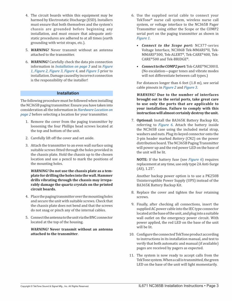
4. The circuit boards within this equipment may be harmed by Electrostatic Discharge (ESD). Installers must ensure that both themselves and the system’s chassis are grounded before beginning any installation, and must ensure that adequate anti-static procedures are adhered to at all times (earth grounding with wrist straps, etc.).
5. WARNING! Never transmit without an antenna attached to the transmitter.
6. WARNING! Carefully check the data pin connection information in Installation on page 3 and in Figure 1, Figure 2, Figure 3, Figure 4, and Figure 5 prior to installation. Damage caused by incorrect connection is the responsibility of the installer!
Installation
The following procedure must be followed when installing the NC365B paging transmitter. Ensure you have taken into consideration all the information in Hardware Location on page 2 before selecting a location for your transmitter.
1. Remove the cover from the paging transmitter by loosening the four Phillips head screws located at the top and bottom of the unit.
2. Carefully lift off the cover and set aside.
3. Attach the transmitter to an even wall surface using suitable screws fitted through the holes provided in the chassis plate. Hold the chassis up to the chosen location and use a pencil to mark the positions of the mounting holes.
WARNING! Do not use the chassis plate as a tem-plate for drilling the holes into the wall. Hammer drills vibrating through the chassis may irrepa-rably damage the quartz crystals on the printed circuit boards.
4. Place the paging transmitter over the mounting holes and secure the unit with suitable screws. Check that the chassis plate does not bend and that the screws do not snag or pinch any of the internal cables.
5. Connect the antenna to the unit via the BNC connector located at the top of the housing.
WARNING! Never transmit without an antenna attached to the transmitter.
6. Use the supplied serial cable to connect your TekTone® nurse call system, wireless nurse call system, or voltage interface to the NC365B Pager Transmitter using either the Scope or the COMP2 serial port on the paging transmitter as shown in Figure 1.
• Connect to the Scope port: NC377-series Voltage Interface, NC386B Tek-MMARS®II, Tek-MMARS®300, Tek-ALERT®, Tek-CARE®400, Tek-CARE®500 and Tek-BRIDGE®.
• Connect to the COMP2 port: Tek-CARE®NC300 II. (No escalation—pager tones and vibrate modes will not differentiate between call types.)
For distances longer than 6 feet (1.8 m), see serial cable pinouts in Figure 2 and Figure 3.
WARNING! Due to the number of interfaces brought out to the serial ports, take great care to use only the ports that are applicable to your installation. Failure to comply with this instruction will almost certainly destroy the unit.
7. Optional: Install the BA365K Battery Backup Kit, referring to Figure 6. Attach the battery inside the NC365B case using the included metal strap, washers and nuts. Plug its keyed connector onto the 3-pin header marked Battery (CN2) on the power distribution board. The NC365B Paging Transmitter will power up and the red power LED on the base of the unit will be lit.
NOTE: If the battery fuse (see Figure 6) requires replacement at any time, use only type 2A Anti-Surge (AS), 1.25".
Another backup power option is to use a PK250B Uninterruptible Power Supply (UPS) instead of the BA365K Battery Backup Kit.
8. Replace the cover and tighten the four retaining screws.
9. Finally, after checking all connections, insert the supplied AC power cable into the IEC type connector located at the base of the unit, and plug into a suitable wall outlet on the emergency power circuit. With power applied, the red LED on the base of the unit will be lit.
10. Configure the connected TekTone product according to instructions in its installation manual, and test to verify that both automatic and manual (if available) pages are received by pagers as expected.
11. The system is now ready to accept calls from the TekTone system. When a call is transmitted, the green LED on the base of the unit will light momentarily.

Page 4 • IL671 NC365B Installation Instructions Copyright © TekTone Sound & Signal Mfg., Inc. All Rights Reserved.
DRY CONTACT INPUTS
COMP2 SCOPEA.C.120V
IL671 NC365B transmitter Rev0 011915
PIN SIGNAL DIRECTION 1 Not Connected 2 Receive Data RX (in) 3 Transmit Data TX (out) 4 Data Terminal Ready DTR (out) 5 Ground GND 6 Not Connected 7 Request to Send RTS (out) 8 Clear to Send CTS (in) 9 Not Used
Scope & COMP2 Serial Ports Pinout (9-pin D-type connector)
Figure 1—NC365B Paging Transmitter Bottom Panel
Figure 2—Serial Cable to Connect Tek-CARE®NC110/NC150/NC200, Tek-MMARS®300, Tek-CARE®400, Tek-CARE®500 or Tek-ALERT®
Figure 3—Serial Cable to connect Tek-CARE®NC300 II System
NC377, NC386B, PM454
DB9 Female ConnectorNC365B Paging Transmitter
DB9 Female Connector
IL67
1 S
eria
l Cab
le R
3 03
0615
.ai
GroundReceive DataTransmit Data
DTRDSRRTSCTS RTS
Receive DataTransmit Data
CTS
DSRDTR
Ground
50′ Maximum
Paging Port on
or Tek-BRIDGE®
NOTE: If shielded cable is used, tie shield to Pin 5 on only one plug.
NC351, NC351/2 Central Equip.DB9 Female Connector
NC365B Paging TransmitterDB9 Female Connector
IL67
1 N
C30
0II S
eria
l Cab
le R
2 02
2015
.ai
Signal GroundReceive DataTransmit Data
DTRDSRRTSCTS Signal Ground
Receive DataTransmit Data
DCD
DSRRTS
Ground
50′ Maximum
Paging Port on
IL671 NC365B Installation Instructions • Page 5Copyright © TekTone Sound & Signal Mfg., Inc. All Rights Reserved.
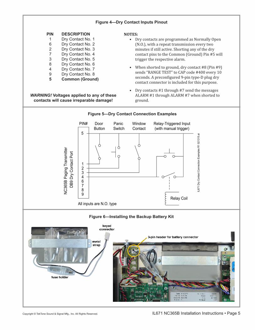
Figure 6—Installing the Backup Battery Kit
Figure 5—Dry Contact Connection Examples
5
12346789
Relay Coil
Door Button
Panic Switch
WindowContact
Dry Contact Connection Examples
All inputs are N.O. type
DB9
Dry
Con
tact
Por
t
PIN# Relay-Triggered Input(with manual trigger)
NC
365B
Pag
ing
Tran
smitt
er
IL67
1 D
ry C
onta
ct C
onne
ctio
n Ex
ampl
es R
1 02
1315
.ai
PIN DESCRIPTION 1 Dry Contact No. 1 6 Dry Contact No. 2 2 Dry Contact No. 3 7 Dry Contact No. 4 3 Dry Contact No. 5 8 Dry Contact No. 6 4 Dry Contact No. 7 9 Dry Contact No. 8 5 Common (Ground)
NOTES:• Dry contacts are programmed as Normally Open
(N.O.), with a repeat transmission every two minutes if still active. Shorting any of the dry contact pins to the Common (Ground) Pin #5 will trigger the respective alarm.
• When shorted to ground, dry contact #8 (Pin #9) sends “RANGE TEST” to CAP code #400 every 10 seconds. A preconfigured 9-pin type-D plug dry contact connector is included for this purpose.
• Dry contacts #1 through #7 send the messages ALARM #1 through ALARM #7 when shorted to ground.
WARNING! Voltages applied to any of these contacts will cause irreparable damage!
Figure 4—Dry Contact Inputs Pinout

Page 6 • IL671 NC365B Installation Instructions Copyright © TekTone Sound & Signal Mfg., Inc. All Rights Reserved.
Add PagersThe NC365B Paging Transmitter transmits to pagers at 1200 baud. NC397A (Scope) Pagers have been pre-programmed to receive at 1200 baud, so no changes are necessary.
NC399P (CommTech) Pagers have been pre-programmed to receive at 512 baud. To use these pagers with the NC365B Paging Transmitter, reprogram them to receive at 1200 baud as described in Appendix: Reprogramming NC399P Pagers on page 7.
For instructions on adding a pager to an NC386B Tek-MMARSII, Tek-MMARS300, Tek-ALERT, Tek-CARE400, Tek-CARE500 or Tek-BRIDGE, please see the system’s installation manual.
For instructions on adding a pager to a Tek-CARE NC110, NC150 or NC200 Nurse Call System, please see the installation manual for the NC377 Voltage Interface (Paging Interface Adapter).
Dry ContactsThe NC365B Paging Transmitter supports up to 8 dry (voltage-free) contacts (see diagram in Figure 1), which, when shorted to ground, will send a pre-programmed message to a particular pager address (which could be to an individual, a group or all pager operatives at the same time). These messages are preprogrammed and can only be changed by qualified service personnel (see pinout in Figure 4).
• Dry contacts #1 through #7 send the messages ALARM #1 through ALARM #7.
• When shorted to ground, dry contact #8 (Pin #9) sends “RANGE TEST” to CAP code #400 every 10 seconds. A preconfigured 9-pin type-D range test dummy plug is included for this purpose.
The trigger time required to send a message must be greater than 1 second. As a default, contacts are programmed as Normally Open (N.O.), with a repeat transmission every two minutes if still active.
LED IndicatorsConfirmation of power connection is provided by the red LED on the base of the paging transmitter.
Confirmation of transmit is provided by the momentary green LED on the base of the paging transmitter.
Equipment TestingConduct range tests at least once a week; more often when critical criteria apply. This involves testing the unit past the limit of its required working range, so as to ensure a measure of safety. The physical range tests are essential, and any construction work or movement of plant or equipment could alter the signaling capability of the unit. Use a pager with CAP code #400 and the included range test connector as described Dry Contacts on page 6 to perform range tests.
TekTone suggests keeping a log of test dates and the information gathered, along with battery change data and service records. Required test frequency varies between applications. If a pager has been dropped or is worn by someone involved in an accident, test the unit again before reuse.
Troubleshooting
IMPORTANT: Disconnect power before removing cover. Internal access and adjustments are strictly limited to authorized service personnel only.
1. Check and re-check the data cable connections. This, together with an incorrect signaling format, results in more faults than any other problem.
2. Check that the communications baud rate of the host equipment is set to 9600, N, 8, 1 to match the Scope or COMP2 serial port.
3. Check that the pagers are at least 10 feet (3 m) from the transmitter and antenna. Under certain conditions it is possible to flood the pager receivers and corrupt the data received.
4. Check that the pagers have their batteries installed with the correct polarity and are correctly powered up.
5. Verify that the correct pager number is being used.
6. Check that the red power LED on the base of the paging transmitter is lit. If not, remove the power cord and check that power is available at the supply outlet.
7. Check that the green LED is lit for the duration of the transmission. If not, go back to the data cabling and re-check the signal format.
8. Verify that the antenna is correctly installed.
9. Verify that the pager is within range.

IL671 NC365B Installation Instructions • Page 7Copyright © TekTone Sound & Signal Mfg., Inc. All Rights Reserved.
Appendix: Reprogramming NC399P Pagers
NC399P (CommTech) Pagers have been pre-programmed to receive at 512 baud. To use these pagers with the NC365B Paging Transmitter, reprogram them to receive at 1200 baud as described below.
There are two versions of the NC399P, version 7900 and version 7950. To determine your pager’s version, see Figure 7.
Reprogram a Version 7900 PagerFirst, start programming mode:• Remove the battery. • Reinsert the battery backwards and wait about two
seconds. Then remove the battery.• Press the read button while reinserting it correctly (see
Figure 7 for button locations). • Release the read button, and the screen will display
MNL PROGRAM.
Next, enter the password:• Press the read button. The screen will display [0000]. • Press the read button, and then press the right button
twice. • The screen will display [0200]. This is the pager’s
password. • Press the read button three times to continue.
Finally, change the baud rate to 1200:• The screen will display the Pager ID/CAP code settings
for ID1 through ID6. Do not change these settings.
• Press the read button repeatedly until the screen displays BAUD: 512. Use the right button to select 1200 baud and then press the read button.
• The screen will display FRE 457.5500, the paging frequency used by all TekTone systems. Press the read button.
• The screen will display PROGRAM YES? Press the read button to reprogram the pager with the new settings, or press the escape button to exit programming mode and retain the pager’s old settings.
• The pager is ready to be used with the NC365B Paging Transmitter.
Reprogram a Version 7950 PagerFirst, start programming mode:• Press and hold the read and escape buttons until the
screen displays PASSWORD: 0000 (see Figure 7 for button locations).
• Release the read and escape buttons.
Next, enter the password:• Press the right button. The screen will display [0000]. • Press the escape button twice. • The screen will display [0200]. This is the pager’s
password.
Finally, change the baud rate to 1200:• Press the left button repeatedly, until this is displayed:
BAUDRATE: 512 BPSPOLARITY: NORMALFREQ : 457.5500 M PROGRAM EXIT
Do not change the paging frequency; 457.5500 is used by all TekTone systems.
• Press the left button repeatedly to highlight 512, and then press the escape button to change it to 1200.
• Press the left or right button until PROGRAM is high-lighted, and then press the read button to reprogram the pager with the new settings. (Or, highlight EXIT and then press the read button to exit programming mode and retain the pager’s old settings.)
• The pager is ready to be used with the NC365B Paging Transmitter.
Figure 7—NC399P Pagers
Version 7900:• The read button scrolls through the menu options.• The left and right buttons change field values.
Version 7950:• The left and right buttons scroll through the
menu options.• The read and escape buttons change field values.