technology review - engine.od.uaengine.od.ua/ufiles/wartsila-20061.pdf · technology review this is...
TRANSCRIPT

Technology review


Technology review
This is a brief guide to the technical features and benefitsof the SULZER® RT-flex60C low-speed marine diesel engines.
Introduction 4
Development background 6
Sulzer RT-flex: Concept and benefits 8
Sulzer RT-flex system applied 10
Real in-service fuel economy 12
Cleaner in the environment 14
Piston-running behaviour 16
Engine structure 18
Running gear 20
Combustion chamber 22
Turbocharging and scavenge air system 24
Installation aspects 25
Maintenance 26
Main technical data 27

Introduction
The Sulzer RT-flex60C low-speed marine diesel engines are tailor-made for
the economic propulsion of container feeder vessels to serve the growing
fleets of the major container lines. They are equally suitable for other vessel
types such as reefers and car carriers with similar requirements.
In these roles, they offer clear and substantial benefits:
� Competitive first cost
� Lowest possible fuel consumption over the whole operating range
� Three years’ time between overhauls
� Low maintenance costs owing to reliable and proven design
� Extremely good ‘slow steaming’ capability through the Sulzer RT-flex
technology which offers a high degree of operational flexibility
� Full compliance with the NOX emission regulation of Annexe VI of the
MARPOL 1973/78 convention
� Smokeless operation even at lowest loads and speeds owing to the Sulzer
RT-flex technology
4
Sulzer 7RT-flex60C, of 16,520 kW at 114 rpm.

5
Development of the Sulzer RT-flex60C engine type was initiated in 1999. It
was seen that the changing container ship newbuilding market was
changing, not just at the upper end with the container liners but also in the
middle range employed as feeder vessels. With container liner newbuildings
becoming larger, with capacities of 5500TEU or more becoming common,
and very many such vessels being contracted, it was clear that more
container feeder vessels would be needed, of possibly up to 3000TEU
capacity.
Such feeders need to
be fast and efficient, calling
for compact prime movers
in the power range of
around 12,000 to 19,000
kW, which became the
power range for the
RT-flex60C engine type.
Development of the
Sulzer RT-flex system of
electronically-controlled
common-rail fuel injection and exhaust valve actuation was timely and has
enabled the introduction of marine diesel engines with clear user benefits.
Principal parameters of Sulzer RT-flex60C engines
Bore mm 600
Stroke mm 2250
Output, R1 kW/cylbhp/cyl
23603210
Speed range, R1-R3 rpm 114–91
BMEP at R1 bar 19.5
Pmax bar 155
Mean piston speed at R1 m/s 8.55
Number of cylinders 5–8
BSFC:
at full load, R1
at 85% load, R1
g/kWhg/bhphg/kWhg/bhph
170125167123
Output kW
80 000
60 000
50 000
40 000
30 000
20 000
10 000
8 000
6 000
4 000
rev/min
Output bhp
100 000
80 000
60 000
40 000
20 000
10 000
8 000
6 000
60 70 80 90 100 120 140
Engine speed
RTA72U-B
RTA52U-BRTA84T-D
RTA68T-B
RTA58T-BRT-flex58T-B
RTA48T-B
RTA96C
RTA84C
RTA62U-B
RT-flex60C

Development background
Wärtsilä has a policy of continuously updating its engine programme and
engine designs to adapt them to the latest market requirements and to
deliver the benefits of technical improvements. The Sulzer RT-flex60C
engine type is a good example of this policy.
The RT-flex60C incorporates many of the design features developed for
the whole series of RTA-T as well as for the RTA96C engines. Particular care
was taken to bring into account all recent service experience to obtain
further improvement in the reliability of the new engine type. Troublefree
operation is the primary goal.
It is more cost-effective to achieve these design objectives with a
completely new engine design rather than further adapting existing engine
designs. The opportunity was taken with a completely new design also to
optimise its powers and speeds to suit the envisaged ship applications.
The RT-flex60C is the first Sulzer low-speed engine to incorporate the
RT-flex system with electronically-controlled common-rail technology as
6
Sulzer RT-flex60C.

standard from the outset. It is not planned to offer the engine in a
conventional camshaft version. The decision to follow this path was taken
after the very positive reception by shipowners of the Sulzer RT-flex system
after it was first applied to a full-scale research engine in June 1998. The
RT-flex system offers distinctive operational benefits which are not possible
with camshaft engines.
The first RT-flex engine went into shipboard service in September 2001,
sufficiently before the first RT-flex60C was built in 2002 to incorporate the
service experience.
The RT-flex60C engine also incorporates TriboPack technology from the
outset. TriboPack design measures, today a well accepted standard, provide
important improvements in piston-running behaviour, for more reliability,
longer times between overhauls and lower cylinder oil feed rates.
7

Sulzer RT-flex: Concept and benefits
The Sulzer RT-flex system is the result of a long project since the 1980s to
develop Sulzer low-speed marine engines without the constraints imposed
by mechanical drive of fuel injection pumps and valve actuation pumps but
with far greater flexibility in engine setting to reach future requirements.
The objective is to deliver operational benefits to the shipowners.
The resulting Sulzer RT-flex60C is basically a standard Sulzer low-speed
two-stroke marine diesel engine, except that, instead of the usual camshaft
and its gear drive, fuel injection pumps, exhaust valve actuator pumps and
reversing servomotors, it is equipped with a common-rail system for fuel
injection and exhaust valve actuation, and full electronic control of these
engine functions.
The common-rail injection system operates with just the same grades of
heavy fuel oil as are already standard for Sulzer RTA-series engines.
The Sulzer RT-flex engine offers a number of interesting benefits to
shipowners and operators:
� Smokeless operation at all operating speeds
� Lower steady running speeds, in the range of 10-12 per cent nominal
speed, obtained smokelessly through sequential shut-off of injectors
while continuing to run on all cylinders
8
Volumetricfuel injectioncontrol unit
Fuelinjectors
Exhaustvalveactuator
Exhaustvalveactuatingunit
Crankanglesensor
WECS9500control system
50m
6m
30 bar starting air
200 bar servo oil
1000 bar fuel HFO / MDO
Schematic of the Sulzer RT-flex system with electronically-controlled common-rail systems.

� Reduced running costs through lower part-load fuel consumption and
longer times between overhauls
� Reduced maintenance requirements, with simpler setting of the engine.
The ‘as-new’ running settings are automatically maintained
� Reduced maintenance costs through precise volumetric fuel injection
control leading to extendable times between overhauls. The common-rail
system with its volumetric control gives excellent balance in engine
power developed between cylinders and between cycles, with precise
injection timing and equalised thermal loads
� Reliability is given by long-term testing of common-rail hardware, and
use of fuel supply pumps based on well-proven Sulzer four-stroke fuel
injection pumps
� Higher availability owing to the integrated monitoring functions
� High availability also given by the built-in redundancy, as full power can
be developed with one fuel pump and one servo oil pump out of action.
High-pressure fuel and servo-oil delivery pipes, and the electronic
systems are also duplicated for redundancy.
9

Sulzer RT-flex system applied
The common rail for fuel injection is a manifold running
the length of the engine at just below the cylinder cover
level. The common rail and other related pipework are
neatly arranged on the top engine platform and readily
accessible from above.
The common rail is fed with heated fuel oil
at the usual high pressure (nominally 1000 bar)
ready for injection. The supply unit has a
number of high-pressure pumps running on multi-
lobe cams. The pump design is based on the proven
injection pumps used in Sulzer four-stroke engines.
Fuel is delivered from this common rail through a separate
injection control unit for
each engine cylinder to the
standard fuel injection
valves which are
hydraulically operated in
the usual way by the
high-pressure fuel oil. The control units,
using quick-acting Sulzer rail valves,
regulate the timing of fuel injection,
control the volume of fuel injected, and
set the shape of the injection pattern. The
three fuel injection valves in each
cylinder cover are separately controlled
so that, although they normally act in
unison, they can also be programmed to operate separately as necessary.
The key features of the Sulzer common-rail system are:
� Precise volumetric control of fuel injection, with integrated flow-out
security
� Variable injection rate shaping and free selection of injection pressure
� Stable pressure levels in common rail and supply pipes
� Possibility for independent control and shutting off of individual fuel
injection valves
� Ideally suited for heavy fuel oil through clear separation of the fuel oil
from the hydraulic pilot valves
� Well-proven standard fuel injection valves
� Proven, high-efficiency common-rail fuel pumps.
10
CAD drawing of the rail unit open to show the common-rail systems for fuel (brown) and servo oil (yellow).
The main elementsof the RT-flexsystem can be seenin yellow: the supply unitwith fuel and servo oilpumps, the rail unitalongside the cylinders, andthe servo oil filter on theother side.
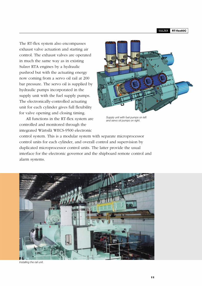
The RT-flex system also encompasses
exhaust valve actuation and starting air
control. The exhaust valves are operated
in much the same way as in existing
Sulzer RTA engines by a hydraulic
pushrod but with the actuating energy
now coming from a servo oil rail at 200
bar pressure. The servo oil is supplied by
hydraulic pumps incorporated in the
supply unit with the fuel supply pumps.
The electronically-controlled actuating
unit for each cylinder gives full flexibility
for valve opening and closing timing.
All functions in the RT-flex system are
controlled and monitored through the
integrated Wärtsilä WECS-9500 electronic
control system. This is a modular system with separate microprocessor
control units for each cylinder, and overall control and supervision by
duplicated microprocessor control units. The latter provide the usual
interface for the electronic governor and the shipboard remote control and
alarm systems.
11
Supply unit with fuel pumps on leftand servo oil pumps on right.
Installing the rail unit.

Real in-service fuel economy
Although Sulzer RTA-series engines have excellent fuel consumption in
general, the Sulzer RT-flex system enables further improvements in the
part-load range. The full-load efficiency of the RT-flex60C remains the same
as equivalent conventional RTA engines.
The RT-flex system offers advantages because of the freedom allowed
in selecting optimum injection pressure, fuel injection timing and exhaust
valve timing at all engine loads or speeds, while ensuring efficient
combustion at all times, even during dead slow running.
Similar freedom in exhaust valve timing allows the RT-flex system to
keep combustion air excess high by earlier closing as the load/speed is
reduced. This is not only advantageous for fuel consumption but also limits
component temperatures, which normally increase at low load. Lower
turbocharger efficiencies at part load normally result in low excess
combustion air with fixed valve timing.
12

Another important contribution to fuel economy of the RT-flex60C engines
is the capability to adapt easily the injection timing to various fuel
properties having a poor combustion behaviour. Variable injection timing
(VIT) over load has been a traditional feature of Sulzer low-speed engines
for many years, using a mechanical arrangement primarily to keep the
cylinder pressure high for the upper load range. This is much easier to
arrange in an electronically-controlled engine. Yet the settings for
compliance with the NOX limit have to be maintained.
An important contribution to the overall fuel consumption can come
from exhaust heat recovery. The RT-flex60C offers a clear advantage in this
respect with an exhaust gas temperature of 285 °C for an unsurpassed high
potential for waste heat recovery. High exhaust temperatures are traditional
for Sulzer low-speed engines. They are obtained by efficient scavenging
processes.
13
The Gypsum Centennial is powered by a Sulzer 6RT-flex58T-B engineand was delivered in September 2001.

Cleaner in the environment
With the current popular concern about the environment, exhaust gas
emissions have become an important aspect of marine diesel engines. All
Sulzer RTA engines comply with the NOX emissions limit of Annex VI of the
MARPOL 73/78 convention as standard.
RT-flex engines, however, come comfortably below this NOX limit by
virtue of their extremely wide flexibility in optimising the fuel injection and
exhaust valve processes.
The most visible benefit of RT-flex engines is, of course, their smokeless
operation at all ship speeds. This is achieved by the superior combustion
gained with the common-rail system. It enables the fuel injection pressure
to be maintained at the optimum level irrespective of engine speed. In
addition, at very low speeds, individual injectors are selectively shut off and
the exhaust valve timing adapted to help to keep smoke emissions below
the visible limit. In contrast, engines with the traditional jerk-type injection
pumps have increasing smoke emissions as engine speed is reduced
because the fuel injection pressure and volume decrease with speed and
power, and they have no means of cutting off individual injection valves
and changing exhaust valve timing.
14
HFO380 cSt3 % sulphur0.1 % ash
ON OFF Aux. blower
Smoke visibility limit
Conventional low-speed engine
6RT-flex58T-B with common rail
Filt
ersm
oke
num
ber
(FS
N)
Engine load (%)
0 10 20 30 40 50 60 70 80 90 100
0.50
0.45
0.40
0.35
0.30
0.25
0.20
0.15
0.10
0.05
0.00
Smoke measurements from the sea trials of the Gypsum Centennial demonstrate the smokeless operation on theRT-flex engine compared with the conventional low-speed marine engine.

Yet the environmental benefits of RT-flex engines need not be
restricted by the current state-of-the-art. As all settings and adjustments
within the combustion and scavenging processes are made
electronically, future adaptations will be possible simply through
changes in software, which could be readily retrofitted to existing
RT-flex engines.
For example, one possibility for future development would be to
offer different modes for different emissions regimes. In one mode,
the engine could be optimised for minimum fuel consumption while
complying with the global NOX limit. Then to satisfy local emissions
regulation the engine could be switched to an alternative mode for
even lower NOX emissions while the fuel consumption may be
allowed to increase.
As well as investigating the scope of possibilities of the RT-flex
system, Wärtsilä is carrying out a long-term research programme to
develop techniques for further reducing exhaust emissions, including
NOX, SOX and CO2.
15

Piston-running behaviour
Today the time between overhaul (TBO) of low-speed marine diesel
engines is largely determined by the piston-running behaviour and its effect
on the wear of piston rings and cylinder liners. For this reason, today’s
Sulzer RTA-series engines incorporate TriboPack technology - a
combination of design measures that enable the TBO of the cylinder
components, including piston ring renewal to be extended to at least three
years. At the same time, TriboPack offers more safety for piston running
under adverse conditions and thus allows standard cylinder lubricating oil
feed rates to be as low as 1.0 g/kWh and even less.
The design measures incorporated in TriboPack are:
� Multi-level cylinder lubrication
� Liner of the appropriate material, with sufficient hard phase
� Careful turning of the liner running surface and deep-honing of the liner
over the full length of the running surface
� Insulating tubes in the cooling bores in the upper part of the liner
� Mid-stroke liner insulation
� Pre-profiled piston rings in all piston grooves.
� Chromium-ceramic coating on top piston ring
� RC (Running-in Coating) piston rings in all lower piston grooves
� Anti-Polishing Ring (APR) at the top of the cylinder liner
� Increased thickness of chromium layer in the piston ring grooves.
16
Cr-ceramicpre-profiled
Top Piston Ring
MultilevelLubrication
Anti-polishingRing
Linerfullydeephoned
Mid-strokeInsulation
LinerInsulation
Lower ringspre-profiled
and RC-coated
Thickchromium
layer
Sulzer TriboPack is a package of design measures giving much improved piston-running behaviour, lower wear rates, threeyears' time between overhauls, and lower cylinder lubricant feed rates.

Deep-honed liners soon achieve a mirror surface.
Most of the design measures in TriboPack have been employed in Sulzer RTA
engines for several years. They are now combined systematically as a standard
package. Although each individual measure of TriboPack improves
piston-running behaviour, only the application of the complete package delivers
the full benefits to the shipowners.
A key element of TriboPack is the deep-honed liner. Careful machining and
deep honing gives the liner an ideal running surface for the piston rings, together
with an optimum surface microstructure. The RT-flex60C has four piston rings, all
16 mm thick and of the same geometry.
The Anti-Polishing Ring prevents the build up of deposits on the top land of
the piston which can cause bore polishing on the liner and damage the oil film.
Whilst trying to avoid corrosive wear by appropriate optimising of liner wall
temperatures, it is necessary to keep as many water droplets as possible out of
engine cylinders. Thus, a newly developed, highly-efficient vane-type water
separator after the scavenge air cooler and the effective water drainage
arrangements are absolutely essential for good piston running.
Load-dependent cylinder lubrication is provided by the well-proven Sulzer
multi-level accumulator system. The lubricating pumps are driven by
frequency-controlled electric motors. On the cylinder liner, oil distributors bring
the oil to the different oil accumulators. For ease of access, the quills are
positioned in dry spaces instead of in the way of cooling water spaces.
17
Piston of the RT-flex60C.

Engine structure
The structure of the RT-flex60C engine is similar in concept to those of
previous Sulzer RTA-series engines with the well-proven, sturdy bedplate
surmounted by very rigid, A-shaped double-walled columns, and cylinder
blocks, all secured by pre-tensioned vertical tie rods. The whole structure is
very sturdy with low stresses and high stiffness. Both bedplate and columns
are welded fabrications that are also designed for minimum machining.
Bedplate stiffness is one of many prerequisites for a sound bearing
performance. A stiff
bedplate can, to some
extent, limit the adverse
influence of excessive
flexibility in some
modern ship designs.
A high overall
structural rigidity is of
major importance.
Accordingly the design is
based on extensive stress
and deformation
calculations carried out
by using a full three-dimensional multi-cylinder
finite-element computer model for different
column designs to verify the optimum frame
configuration.
The cylinder jacket is a single-piece iron
casting. The height of the cylinder jacket is
determined by the space required for the
scavenge air receiver. Access to the piston
under-side is possible from the receiver side of
the engine, to allow for maintenance of the
piston rod gland and also for inspecting piston
rings. On the fuel side, one door per cylinder
can be opened for inspection and to support
in-engine work from outside
18
Column of 7RT-flex60C engine.
Cylinder block of 7RT-flex60C engine.

The tilting-pad thrust bearing is
integrated in the bedplate. The pads
are arranged to ensure a safe,
uniform load distribution. The
thrust-bearing girder consists of only
two steel cast pieces, omitting
welding seams in critical corners.
The girder is clearly stiffer than in
previous designs.
19
Bedplate of the 7RT-flex60C with main bearing caps in place.
Bedplate of 7RT-flex60Cengine.
Finite-element model of the RT-flex60Cstructure for computer analysis.

Running gear
The running gear comprises the crankshaft, connecting rods
and piston rods together with their associated bearings and
piston rod glands.
The semi-built crankshaft of the RT-flex60C engine was
carefully optimised by three-dimensional finite-element
analysis. Special care was taken for the fillet areas and the
shrink fits to cope with the compact cylinder distances.
The main bearings are of white metal on thin steel shells.
To achieve greater precision in the geometry of the mounted
bearing shells and thereby improved running safety, the
main bearing bores are co-machined with the bearing caps
mounted and tightened.
A much improved understanding of the real behaviour of
main bearings and their loads was obtained by combining
the latest finite-element analysis and elasto-hydrodynamic
calculation techniques considering the whole engine
structure including shaft vibrations. This remarkable gain in
knowledge, which could be verified with service results, was
fully incorporated in the RT-flex60C engine.
The crosshead has a full-width lower bearing as in other
RTA engines but is simplified in design. The pin is of a
uniform diameter and the two guide shoes are made in
20
Section of the piston rodgland of the RT-flex60C.
Connecting rod ofthe RT-flex60C.
Thrust bearing of 7RT-flex60C engine with the supply unitdrive gear on the thrust collar. The flywheel is to the right.

single steel castings with white metal-plated running surfaces. Special care
was taken to give the guide shoe ample flexibility to adapt well to the
natural deformation of the guide rails under load. The crosshead bearing
design features a full-width shell for the lower half bearing. Sulzer
low-speed engines retain the use of a separate elevated-pressure lubricating
oil supply to the crosshead. It provides hydrostatic lubrication which lifts
the crosshead pin off the bearing at every revolution. This ensures that
sufficient oil film thickness is maintained under all circumstances.
Extensive development work has been put into the piston rod gland
because of its importance in keeping crankcase oil consumption down to a
reasonable level and maintaining the quality of the system oil.
The RT-flex60C uses a new gland design which is already employed in
the RTA68T-B and in some RTA84C engines. It combines the well proven
and highly effective dirt scraping top part with an effective system oil
scraping ring design in the lower part. The oil scraping is provided by six
spring-loaded grey cast-iron segments which run on a hardened piston rod.
Oil can flow back to the crankcase through many large vertical holes. The
result is that there is practically no flow from the neutral space. Instead
there is a complete internal re-circulation of the scraped-off oil into the
crankcase and the system oil consumption
is expected to stabilise.
21
Piston and piston rodequipped with gland box.
Crankshaft of7RT-flex60C engine.

Combustion chamber
The combustion chamber is a key issue for an engine’s reliability. Careful
attention is needed for the piston cooling, as well as for the layout of the
fuel injection spray pattern to achieve moderate surface temperatures and to
avoid carbon deposits. Low combustion chamber temperatures are not only
responsible for long times between overhauls but also desirable to have a
higher degree of freedom to reach low NOX emissions.
At Wärtsilä, the optimisation of the fuel injection is simulated with
modern calculation tools, such as CFD (computerised fluid dynamics)
analysis and then is confirmed on the engine.
The well-proven bore-cooling is also adopted in all combustion
chamber components, together with shaker cooling in the piston, to achieve
high heat transfer coefficients over a long time and thus to control
temperatures and thermal strains as well as mechanical stresses of the
components.
22
400°200°0°
400°
200°
0°
400°
200°
0°
200°
0°
Surface temperatures of the combustion chamber components calculated for full-load conditions.

The bore-cooled steel cylinder cover is secured by eight elastic studs
arranged in four pairs. It is equipped with a single, central exhaust valve in
Nimonic 80A which is housed in a bolted-on valve cage. There are three
fuel injection valves symmetrically distributed in each cylinder cover. This
arrangement of injection valves helps to equalise the temperature
distribution on the piston crown over the circumference around the liner
and in the cylinder cover. Anti-corrosion cladding is applied to the cylinder
covers downstream of the injection nozzles to protect the cylinder covers
from hot corrosive or erosive attack.
The piston comprises a forged steel crown with a very short skirt. The
compact piston contains four rings of the same height, as part of the
TriboPack.
The cylinder liner is bore cooled which has been proven to meet
necessary high demands on temperature distribution. Although insulation
tubes are criticised as being complicated, they do allow an invaluable
adjustment of the temperature distribution in the liner. Yet only local
insulation with physically correct heat conduction parameters, together with
a proper geometry can lead to the desired temperatures and, at the same
time, limit thermal stress.
23
Cooling bores on theunderside of the pistoncrown.

Turbocharging and scavenge air system
The RT-flex60C is uniflow scavenged with air inlet ports in the lower part of
the cylinder and a single, central exhaust valve in the cylinder cover.
Scavenge air is delivered by a constant-pressure turbocharging system with
one or more high-efficiency exhaust gas turbochargers, depending on the
number of cylinders. For starting and during slow running, the scavenge air
delivery is augmented by electrically-driven auxiliary blowers.
The scavenge air receiver is of a simplified and modular design with
integral non-return flaps, hanging cooler bundles and two auxiliary blowers.
The cooler is dismantled vertically. The cooler bundles are made of
high-efficient tubes and fins for compact dimensions, circulated with fresh
water.
The turbochargers are mounted on very stiff brackets. The receiver
carries the fixed foot for the exhaust manifold. The fixed foot contains the
two auxiliary blowers including the whole channelling and auxiliary flaps
needed for low-load operation.
Special attention is given to removing all water condensate before the
air enters the cylinder as this is vital for satisfactory piston running.
Immediately after the cooler, the scavenge air passes a newly developed
water separator of high efficiency. There are ample drainage provisions to
remove completely the condensed water collected at the bottom of the air
cooler and separator. To avoid blow-back through the drains from the
higher pressure areas, all the drains are collected at the bottom of a
vertically mounted pot which is filled with water and kept under scavenge
air pressure. Drain water then leaves from the top of the pot with an orifice
controlling the discharge. This arrangement has no moving parts.
24
Complete scavenging system for aseven-cylinder RT-flex60C engine,comprising exhaust manifold at top,two turbochargers, auxiliary blowers,scavenge air cooler and scavenge airmanifold.

Installation aspects
Sulzer RTA-series engines have specific design features that help to facilitate
their installation on board ship.
The RTA engines have simple seating arrangements with a modest
number of holding down bolts and side stoppers. No end stoppers, thrust
brackets or fitted bolts are needed as thrust transmission is provided by
thrust sleeves which are applied to a number of the holding-down bolts.
The holes in the tank top for the thrust sleeves can be made by drilling or
even flame cutting. After alignment of the bedplate, epoxy resin chocking
material is poured around the thrust sleeves.
All ancillaries, such as pumps and tank capacities, and their
arrangement are optimised to reduce the installation and operating costs.
The engine’s electrical power requirement for the ancillary services,
including auxiliary blowers, cooling water, lubricating oil, fuel supply, etc.,
is kept down to a minimum.
Sulzer RTA engines have a valuable waste heat recovery potential to
generate steam for heating services and for a turbogenerator. The exhaust
gas temperature of an RT-flex60C is some 25°C higher than competitors’
engines, which almost doubles the possible steam production. A two-stage
scavenge air cooler is also possible for waste heat recovery purposes.
The RT-flex60C has a standard all-electric interface for engine
management systems - known as DENIS (Diesel Engine Interface
Specification) - to meet all needs for control, monitoring, safety and alarm
warning functions. An electronically-equipped local control stand for
manual engine operation is standard.
25
Side stopper
Thrust
Arrangements for transmitting propeller thrust to the engine seatings for RT-flex60C engines. The inset shows thethrust sleeve for the thrust bolts.
Maintenance
Primary objectives in the design and
development of Sulzer RTA engines
are high reliability and long times
between overhauls. Three years
between overhauls are now being
achieved by engines to the latest
design standards. At the same time,
their high reliability gives shipowners
more freedom to arrange maintenance
work within ships’ sailing schedules.
Yet, as maintenance work is
inevitable, particular attention is given
to ease of maintenance by including
tooling and easy access, and by
providing easy-to-understand
instructions.
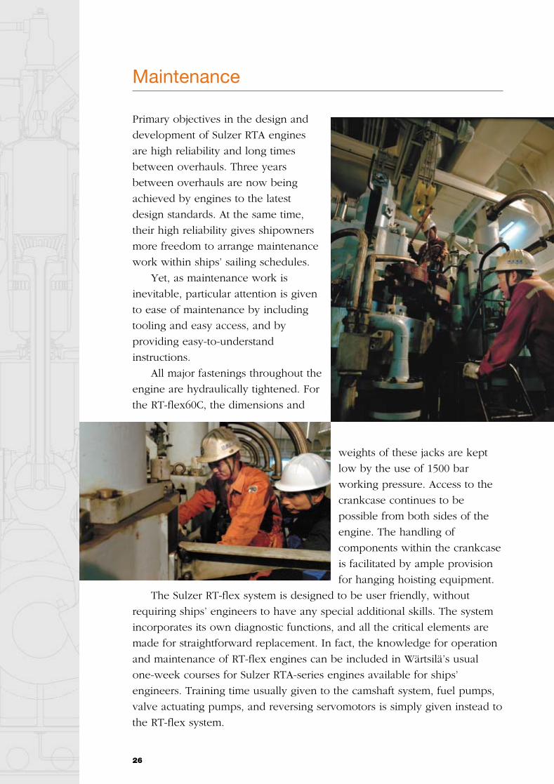
All major fastenings throughout the
engine are hydraulically tightened. For
the RT-flex60C, the dimensions and
weights of these jacks are kept
low by the use of 1500 bar
working pressure. Access to the
crankcase continues to be
possible from both sides of the
engine. The handling of
components within the crankcase
is facilitated by ample provision
for hanging hoisting equipment.
The Sulzer RT-flex system is designed to be user friendly, without
requiring ships’ engineers to have any special additional skills. The system
incorporates its own diagnostic functions, and all the critical elements are
made for straightforward replacement. In fact, the knowledge for operation
and maintenance of RT-flex engines can be included in Wärtsilä’s usual
one-week courses for Sulzer RTA-series engines available for ships’
engineers. Training time usually given to the camshaft system, fuel pumps,
valve actuating pumps, and reversing servomotors is simply given instead to
the RT-flex system.
26

27
Speed
Enginelayoutfield
Engine-MCRPower
R4
R3
R2
R1
Definitions:
� R1, R2, R3, R4 = power/speed ratings at the fourcorners of the RTA engine layout field (seediagram).
� R1 = engine Maximum Continuous Rating (MCR).
� Contract-MCR (CMCR) = selected rating point forparticular installation. Any CMCR point can beselected within the RTA layout field.
� BSFC = brake specific fuel consumption. All figuresare quoted for fuel of net calorific value 42.7 MJ/kg(10 200 kcal/kg) and ISO standard referenceconditions (ISO 3046-1). The BSFC figures aregiven with a tolerance of 5%, without engine-drivenpumps.
� The values of power in kilowatts and fuelconsumption in g/kWh are the official figures anddiscrepancies occur between these and thecorresponding bhp values owing to the rounding ofnumbers.
� ISO standard reference conditionsTotal barometric pressure . . . . . . . . . . . . . 1.0 barSuction air temperature . . . . . . . . . . . . . . . . 25 °CScavenge air cooling-water temperature . . . 25 °CRelative humidity. . . . . . . . . . . . . . . . . . . . . . 60%AK
G
D
C
B
F
E
I
Main technical data
Cylinder bore 600 mm
Piston stroke 2 250 mm
Speed 91 - 114 rpm
Mean effective pressure at R1 19.5 bar
Piston speed 8.5 m/s
Fuel specification:Fuel oil 730 cSt/50°C
7 200 sR1/100°FISO 8217, category ISO-F-RMK 55
Rated power: Propulsion Engines
Cyl.
Output in kW/bhp at
114 rpm 91 rpm
R1 R2 R3 R4
kW bhp kW bhp kW bhp kW bhp
5678
11 80014 16016 52018 880
16 05019 26022 47025 680
8 2509 900
11 55013 200
11 20013 44015 68017 920
9 40011 28013 16015 040
12 80015 36017 92020 480
8 2509 900
11 55013 200
11 20013 44015 68017 920
Brake specific fuel consumption (BSFC)
g/kWh g/bhph g/kWh g/bhph g/kWh g/bhph g/kWh g/bhph
Load 85 % 167 123 164 120 167 123 165 121
Load 100 % 170 125 164 120 170 125 166 122
BMEP, bar 19.5 13.7 19.5 17.0
Principal engine dimensions (mm) and weights (tonnes)
Cyl. A B C D E F* G I K Weight
5678
6 2137 2538 2939 333
3 7003 7003 7003 700
1 3001 3001 3001 300
8 5208 5208 5208 520
3 9603 9603 9603 960
10 40010 40010 40010 400
1 9551 9551 9551 955
400-650400-650400-650400-650
405405405405
290330375415
* Standard piston dismantling height, can be reduced with tilted piston withdrawal.

W03
12/
Boc
k´s
Off
ice
/Fr
am
Wärtsilä Corporation is the leading global ship power supplier and a
major provider of solutions for decentralized power generation and of
supporting services.
In addition Wärtsilä operates a Nordic engineering steel company
Imatra Steel and manages a substantial shareholding to support the
development of its core business.
For more information visit www.wartsila.com
WÄRTSILÄ® and SULZER® are registered trademarks. Copyright © 2003 Wärtsilä Corporation.
Wärtsilä CorporationP.O.Box 196FIN-00531 Helsinki
Tel: +358 10 709 0000Fax: +358 10 709 5700