technology readiness assessment (tra) deskbook
TRANSCRIPT

DEPARTMENT OF DEFENSE
Technology Readiness Assessment (TRA) Deskbook
July 2009
Prepared by the Director, Research Directorate (DRD)
Office of the Director, Defense Research and Engineering (DDR&E)
This version of the TRA Deskbook accounts for policy and guidance provided by Directive DoDD 5000.01, of May 12, 2003 and certified current as of November 20, 2007;
Instruction DoDI 5000.02, dated December 2, 2008; and the online Defense Acquisition Guidebook.

iii
Contents
Executive Summary .................................................................................................. ES-1
1. Introduction ...................................................................................................... 1-1
1.1 Technology Readiness Assessment (TRA) Definition ............................. 1-1
1.2 TRA Authority .......................................................................................... 1-2
1.3 TRA Importance ....................................................................................... 1-3
1.3.1 Milestone B TRA .......................................................................... 1-3 1.3.2 Milestone C TRA .......................................................................... 1-5
1.4 Purpose and Organization of This Document ........................................... 1-5
2. Initiating and Conducting TRAs .................................................................... 2-1
2.1 Key Players and the TRA Timeline .......................................................... 2-1
2.2 Roles and Responsibilities ........................................................................ 2-1
3. Evolution of Knowledge on Technology Maturity ........................................ 3-1
3.1 Early Evaluations of Technology Maturity ............................................... 3-1
3.2 Summary ................................................................................................... 3-3
List of Acronyms .................................................................................................... ACR-1
Appendixes
A Submitting a Technology Readiness Assessment (TRA) ...................................... A-1
B. Guidance and Best Practices for Identifying Critical Technology Elements (CTEs) .................................................................................................... B-1
C. Guidance and Best Practices for Assessing Technology Maturity ......................... C-1
D. Amplifying Technology Readiness Assessment (TRA) Guidance for Ships ........ D-1
E. Biomedical Technology Readiness Levels (TRLs) ................................................ E-1
F Technology Maturity Policy ................................................................................... F-1
G. The Technology Readiness Assessment (TRA) Process ....................................... G-1
H. Easy-Reference Displays of the Hardware/Software TRLs and Additional TRL Definitions ................................................................................... H-1

iv
Figure
2-1. Representative Schedule for TRA Activities ...................................................... 2-2
Table
3-1. Basis of Technology Maturity Assessments Throughout Acquisition ................ 3-3

ES-1
Executive Summary
A Technology Readiness Assessment (TRA) is a formal, systematic, metrics-
based process and accompanying report that assesses the maturity of critical hardware
and software technologies to be used in systems. It is conducted by an Independent
Review Team (IRT) of subject matter experts (SMEs).
This formal TRA complements—but does not in any way preclude—the program
manager’s (PM’s) responsibility to pursue all the risk reduction efforts needed to ensure
that adequate technological maturity is reached before Milestone B approval is sought.
As an activity separate from the formal TRA, an early evaluation of technology maturity
conducted shortly before Milestone A should be used to support the planning of these risk
reduction efforts.
All Department of Defense (DoD) acquisition programs must have a formal TRA
at Milestone B and at Milestone C of the Defense Acquisition System. For ships, a pre-
liminary assessment is required at program initiation. TRAs for Acquisition Category
(ACAT) ID and IAM programs must be submitted to the Director, Research Directorate
(DRD) in the office of the Director of Defense Research and Engineering (DDR&E).
Title 10 United States Code (U.S.C.) Section 2366b requires, in part, that the
Milestone Decision Authority (MDA) certify that the technology being used in Major
Defense Acquisition Programs (MDAPs), including space MDAPs, has been demon-
strated in a relevant environment before Milestone B approval. The Under Secretary of
Defense for Acquisition, Technology, and Logistics (USD(AT&L)) relies on the DDR&E
to provide technical advice to support this certification. In addition, while 10 U.S.C.
2366b is only applicable to MDAPs, the DoD is also requiring Major Automated Infor-
mation System (MAIS) acquisitions to meet the same technology maturity standard at
Milestone B. Consequently, the DDR&E is also providing technical advice to the MDA
for MAIS acquisitions. The DDR&E is using the approved TRA process and report as the
basis of that technical advice.
This document, the Technology Readiness Assessment (TRA) Deskbook, provides
DRD guidance for conducting TRAs. The body of this document is a concise description

ES-2
of suggested best practices, responsibilities, roles, and procedures for meeting the TRA
requirements. The appendixes are designed to amplify the material in the main body.
ACAT ID and IAM programs are expected to follow these best practices as a condition
for certification. The processes outlined should also be used for other MDAPs.
This Deskbook is intentionally generic and non-prescriptive. The Services and
agencies, given their vast organizational structures, are encouraged to establish their own
implementation guidance, approved and endorsed by the Component Science and Tech-
nology (S&T) Executive. Procedures should be based upon the principles, guidance, and
recommended best practices contained in this Deskbook.

1-1
Section 1.
Introduction
1.1 Technology Readiness Assessment (TRA) Definition
A TRA is a formal, systematic, metrics-based process and accompanying report1
that assesses the maturity of technologies called Critical Technology Elements (CTEs)2
to be used in systems. CTEs can be hardware or software. The definition of a CTE is as
follows:
A technology element is “critical” if the system being acquired depends on this technology element to meet operational requirements (within acceptable cost and schedule limits) and if the technology element or its application is either new or novel or in an area that poses major techno-logical risk during detailed design or demonstration.
This definition represents an expansion of previous definitions by adding the
phrase “or in an area that poses major technological risk during detailed design or dem-
onstration.” In the past, some confusion arose in determining whether a CTE is a “tech-
nology” or solely a matter of “engineering.” The purpose of this new phrase is to be more
encompassing. If the technology represents a major risk, it should be identified as a CTE
so that the TRA will include technical information that can be used to mitigate the risk.
An Independent Review Team (IRT) of subject matter experts (SMEs) uses Tech-
nology Readiness Levels (TRLs) as the metric to assess CTE maturity.3 The TRL scale
ranges from one through nine. The definitions are as follows:
TRL 1: Basic principles observed and reported
TRL 2: Technology concept and/or application formulated
TRL 3: Analytical and experimental critical function and/or characteristic proof of concept
TRL 4: Component and/or breadboard validation in a laboratory environment
1 Appendix A contains an annotated outline of the TRA report. 2 Appendix B addresses the CTE identification process in more detail. 3 Appendix C discusses TRLs and CTE maturity assessments in more detail. Appendix D provides some
amplifying guidance for ships. Appendix E addresses biomedical TRLs. Appendix H (at the end of this document) is an easy-reference display of the hardware and software TRLs and additional definitions of TRL descriptive terms.
1-2
TRL 5: Component and/or breadboard validation in a relevant environment
TRL 6: System/subsystem model or prototype demonstration in a relevant environment
TRL 7: System prototype demonstration in an operational environment
TRL 8: Actual system completed and qualified through test and demonstra-tion
TRL 9: Actual system proven through successful mission operations.
CTE lists of varying provenance exist during the TRA. We reserve the term
“CTE” for the final list with the Director, Research Directorate (DRD) concurrence.
“Possible” CTEs are on the list prepared by the program manager (PM), “potential” CTEs
are from pre-Materiel Solution Analysis (MSA) early evaluations of technology maturity,
and “candidate” CTEs represent the IRT product for DRD coordination.
1.2 TRA Authority
The requirement to conduct a formal TRA is established by the following doc-
uments:4,5
Department of Defense Directive (DoDD) 5000.01, The Defense Acquisition System, of May 12, 2003, and certified current as of November 20, 2007
Department of Defense Instruction (DoDI) 5000.02, Operation of the Defense Acquisition System, dated December 2, 2008
Under Secretary of Defense for Acquisition, Technology, and Logistics USD(AT&L) Memorandum on Transition of the Defense Space Acquisition Board (DSAB) Into the Defense Acquisition Board and its interim guidance attachment, dated March 23, 2009
DoDD 5000.01 authorizes the publication of DoDI 5000.02. Together, these doc-
uments provide management principles and mandatory policies and procedures for man-
aging all acquisition programs. DoDI 5000.02 establishes a regulatory requirement for
TRAs. All Department of Defense (DoD) acquisition programs must prepare a TRA at
Milestone B and at Milestone C of the Defense Acquisition System. For ships, a
4 The 5000 series documents are available at https://akss.dau.mil/dapc/index.aspx. A working knowl-edge of the Defense Acquisition System is assumed in the main body of this document.
5 There is no such thing as an informal TRA. While many assessments of technology maturity will be conducted in the science and technology (S&T) environment and in the context of an acquisition program, the term “Technology Readiness Assessment” applies only to this regulatory requirement.

1-3
preliminary assessment is required at program initiation. TRAs for Acquisition Category
(ACAT) ID and IAM programs must be submitted to the DRD. The TRA processes pre-
sented in this document should be adapted to other ACAT programs to fulfill regulatory
and statutory requirements.
The TRA complements—but does not in any way preclude—the PM’s responsi-
bility to pursue all risk reduction efforts needed to ensure that adequate technological
maturity is reached before Milestone B approval is sought. As an activity separate from
the formal TRA, an early evaluation of technology maturity conducted shortly before
Milestone A should be used to support the development of the Technology Development
Strategy (TDS).
1.3 TRA Importance
1.3.1 Milestone B TRA
Programs that enter the Engineering and Manufacturing Development (EMD)
phase of the Defense Acquisition System and have immature technologies will incur cost
growth and schedule slippage. Therefore, Title 10 United States Code (U.S.C.) Section
2366b requires, in part, that the Milestone Decision Authority (MDA) certify that the
technology in Major Defense Acquisition Programs (MDAPs), including space MDAPS,6
has been demonstrated in a relevant environment (TRL 6) before Milestone B approval.
The law allows the MDA to waive the certification requirement (i.e., the technology in
the program has been demonstrated in a relevant environment) if it determines that such a
requirement would hinder the DoD’s ability to meet critical national security objectives.
As a matter of practice, such waivers will be granted only in extraordinary circum-
stances.7 The Under Secretary of Defense for Acquisition, Technology, and Logistics
(USD(AT&L)) has directed that all MDAs—including the Component Acquisition
Executives (CAEs) and the Assistant Secretary of Defense for Networks and Information
Integration (ASD(NII))—for MDAPs will certify without delegation, as required by law.8
6 Statutory language refers to Key Decision Point (KDP) B for space programs. This terminology has been made obsolete by the aforementioned USD(AT&L) memorandum, dated March 23, 2009.
7 Whenever the MDA makes such a determination and authorizes such a waiver, the waiver and the reasons for the determination have to be submitted in writing to the Congressional defense committees within 30 days of waiver authorization.
8 Implementation of Section 2366a of Title 10, United States Code, as amended by the National Defense Authorization Act for FY 2008 (P.L. No. 110-181), USD(AT&L) Memorandum, February 25, 2008, as amended by Policy Update Due To Technical Change in Statute – Reference for Requirement for

1-4
The USD(AT&L) relies on the Director of Defense Research and Engineering
(DDR&E) to provide technical advice to support certification. In addition, while
10 U.S.C. 2366b is only binding for MDAPs, the DoD is also requiring Major Automated
Information System (MAIS) acquisitions to meet the same technology maturity standard
at Milestone B. Consequently, the DDR&E is also providing technical advice to the
MDA for MAIS acquisitions. The DDR&E is using the approved TRA process and report
as the basis of that technical advice.9 DoDI 5000.02 requires Request for Proposal (RFP)
language that prevents the award of an EMD contract if it includes technologies that have
not been demonstrated to be mature. As such, a generic TRA not based on the planned
technical solution is not acceptable. The TRA must be based on the technologies in the
system. This means that TRAs must be performed on all the competitors’ proposals in a
source selection. Under the DDR&E, the DRD has primary responsibility for overseeing
the TRA process and reviewing TRA reports.
PMs have found that the TRA assessment process is useful in managing technol-
ogy maturity. The TRA process highlights critical technologies and other potential tech-
nology risk areas that require the PM’s attention. The TRA can help identify immature
and important components and track the maturity development of those components.
Some programs use TRAs as an important part of their risk assessment.10
For Information Technology (IT) systems, which rely heavily on off-the-shelf
components, TRAs have increased management’s focus on finding CTEs that relate spe-
cifically to IT issues (e.g., interfaces, throughput, scalability, external dependencies, inte-
gration, and information assurance). Since many IT systems have experienced problems
in these areas, the TRA has proven useful in understanding potential problems earlier in
the process, when solution options are easier to adopt and less costly to implement.
1.3.2 Milestone C TRA
Milestone C marks approval to enter low rate initiation production (LRIP) for
hardware systems and limited deployment in support of operational testing for MAIS
programs or for software-intensive systems that have no production components. TRL 7
or higher is the expected state of technology maturity at Milestone C.
Milestone B Certification becomes Section 2366b vice 2366a, Director Acquisition Resources and Analysis Memorandum, November 21, 2008.
9 Appendix F provides more information on how the TRA supports certification. 10 Early evaluations of technology maturity also assist in risk reduction. See Section 3.1.

1-5
The Milestone C TRA is important for several reasons. It reflects the resolution of
any technology deficiencies that arose during EMD. This TRA serves as a check that all
CTEs are maturing as planned. By Milestone C, all CTEs will have advanced and will
continue to be matured through established Technology Maturation Plans (TMPs). Any
new CTEs that have emerged should be identified, and their maturation plans should be
reviewed.
For software, TRL 7 means that all source codes have been written and tested—
not only as an independent module and/or component, but also as integrated into the
whole system. The TRA at Milestone C is important for MAIS programs because it
Documents successful developmental test and evaluation (DT&E)
Examines plans for maintenance and upgrades to ensure that no new CTEs are involved
Determines whether algorithms will transfer successfully when host plat-forms are moved and full-scale applications are initiated in a real operational environment
Identifies where new Milestone B reviews are needed for future releases to initiate efforts to improve performance and determines the architectural changes necessary to support these future releases.
1.4 Purpose and Organization of This Document
This document, the Technology Readiness Assessment (TRA) Deskbook, provides
DRD guidance and best practices for conducting TRAs. ACAT ID and IAM programs are
expected to follow the best practices as a condition for certification. Section 2 presents an
overview of the process and summarizes the roles and responsibilities of the key players
in the process.11 Section 3 describes other TRA activities in the context of an evolution of
knowledge of technology maturity throughout acquisition. The appendixes are designed
to amplify the material in the main body.
11 Appendix G contains a more chronological description of key player roles and responsibilities and highlights best practices.

2-1
Section 2.
Initiating and Conducting TRAs
2.1 Key Players and the TRA Timeline
Key players in the TRA process are as follows:
The PM, the Component S&T Executive, and the CAE are the principal stakeholders for the Component conducting the TRA.
The DRD has primary responsibility for reviewing and evaluating the TRA for the Office of the Secretary of Defense (OSD) for ACAT ID and IAM programs. The Component S&T Executive evaluates the TRA for ACAT ICs. The Component S&T Executive can delegate to the appro-priate MDAs for ACAT II and below. The DRD monitors the TRA process and reports to the DDR&E.
The IRT of SMEs is responsible for conducting the TRA itself.
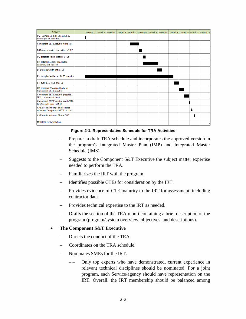
Figure 2-1 shows a representative schedule of activities for a TRA. The “months”
shown across the top of the figure represent the timeline before a milestone decision. The
TRA schedule will vary with the program’s acquisition strategy and should take into
account any source selection or down-select activity. As a result, activity start points and
duration may vary greatly. The time varies as a function of Component procedures.
ACAT ID, IC, and IAM programs typically take a full year or more. Smaller, less com-
plex programs normally require less time.
2.2 Roles and Responsibilities
Key player roles and responsibilities are as follows:
The PM
– Plans and funds the program’s risk reduction activities to ensure that CTEs reach the appropriate maturity levels. For example, the CTEs must be TRL 6 at Milestone B.
– Informs the Component S&T Executive of the need to conduct a TRA.
– Funds the TRA evaluation for his program.
– Designates a responsible individual to organize all TRA activities.
2-2
Figure 2-1. Representative Schedule for TRA Activities
– Prepares a draft TRA schedule and incorporates the approved version in the program’s Integrated Master Plan (IMP) and Integrated Master Schedule (IMS).
– Suggests to the Component S&T Executive the subject matter expertise needed to perform the TRA.
– Familiarizes the IRT with the program.
– Identifies possible CTEs for consideration by the IRT.
– Provides evidence of CTE maturity to the IRT for assessment, including contractor data.
– Provides technical expertise to the IRT as needed.
– Drafts the section of the TRA report containing a brief description of the program (program/system overview, objectives, and descriptions).
The Component S&T Executive
– Directs the conduct of the TRA.
– Coordinates on the TRA schedule.
– Nominates SMEs for the IRT.
– – Only top experts who have demonstrated, current experience in relevant technical disciplines should be nominated. For a joint program, each Service/agency should have representation on the IRT. Overall, the IRT membership should be balanced among

2-3
Component, other government agency (e.g., National Aeronautics and Space Administration (NASA), National Institute of Stan-dards and Technology (NIST), or Department of Energy (DOE)), and non-government representatives (e.g., academia, Federally Funded Research and Development Centers (FFRDCs), or science boards)).
– – Members should be sufficiently independent of the developers (government or industry) so as to not be unduly influenced by their opinions or have any actual or perceived biases. An IRT member should not be directly working for or matrixed to the program to avoid being unduly influenced by the PM.
– Provides the DRD the credentials of all prospective IRT members and sufficient information to confirm their independence from the program.
– Trains IRT members on the TRA process.
– – Training should include an overview of the TRA process, criteria for identifying CTEs, and examples and instructions for the appli-cation of the TRLs.
– Reviews the TRA report and prepares the TRA report cover memoran-dum, which may include additional technical information deemed appro-priate to support or disagree with IRT findings.
– Sends the completed TRA to the CAE for official transmittal to the DRD and furnishes an advance copy to the DRD.
– Maintains continuity in the IRT membership for all TRAs conducted over the life of a program, to the maximum extent possible.
The CAE
– Approves the TRA report cover memorandum.
– Forwards the TRA to the DRD.
The IRT
– Keeps the Component S&T Executive and the DRD informed on progress throughout the entire TRA process.
– Develops a list of candidate CTEs in conjunction with the program.
– – The IRT should make final recommendations (with associated rationale) on the candidate CTEs that should be assessed in the TRA. These recommendations should be based on (1) full access to specific technical planning performed by existing or previous contractors or government agencies, (2) the CTE definition,

2-4
(3) the PM’s answers to questions, (4) professional experience of IRT members, and (5) a PM-prepared initial list of possible CTEs using the most current system design as a starting point. CTE candidates are not constrained to those technologies on the PM’s initial list. Technologies not included on the program’s initial list may be candidates.
– Assesses the TRLs for all CTEs.
– – The assessment must be based on objective evidence gathered during events such as tests, demonstrations, pilots, or physics-based simulations. Based on the requirements, identified capabili-ties, system architecture, software architecture, concept of opera-tions (CONOPS), and/or the concept of employment, the IRT will define relevant and operational environments and determine which TRL is supported by the objective evidence. The IRT can form subteams based on members’ subject matter expertise. These subteams could deliberate on the appropriate TRL and then defend their position to the entire IRT.
– Prepares (or oversees the preparation of) elements of the TRA report including (1) the IRT credentials and (2) IRT deliberations, findings, conclusions, and supporting evidence.
– – The assessment process should not be constrained to a validation of a “program-developed” position on the TRL.
The DRD
– Concurs with the TRA schedule.
– Concurs with the composition of the IRT.
– Reviews the candidate CTE list and identifies any changes necessary to form the final CTE list.
– – Additions to the list can include any special- interest technologies that warrant the rigor of the formal TRA process.
– Exercises oversight by monitoring and evaluating the TRA process and reviewing the TRA report.
– – On the basis of that review, a TRA revision may be requested or the DRD may conduct its own Independent Technical Assessment (ITA).
– Sends the results of its TRA review to the appropriate Overarching Inte-grated Product Team (OIPT) and/or the Defense Acquisition Board (DAB).

2-5
– Provides the DDR&E recommendations concerning certification.
– Recommends technology maturity language for an Acquisition Decision Memorandum (ADM), noting, in particular, conditions under which new technology can be inserted into the program.

3-1
Section 3.
Evolution of Knowledge on Technology Maturity
Assessments of technology readiness or TRA-like activities other than the formal
TRAs at Milestone B and Milestone C take place over the acquisition life cycle. Sec-
tion 3.1 discusses early evaluations of technology maturity. Section 3.2 contains a sum-
mary table illustrating activities throughout acquisition.
3.1 Early Evaluations of Technology Maturity
In the MSA phase, an Analysis of Alternatives (AoA) is conducted to identify
potential materiel solutions, based on a cost-benefit analysis. In parallel, early Systems
Engineering activities, such as the proposed Engineering Analysis of Potential System
Solutions, are conducted. These materiel solutions should then undergo an Early Evalua-
tion of Technological Maturity,12 provided sufficient technical information exists to sup-
port such an evaluation. This evaluation will identify candidate Critical Technologies or
Critical Technology Areas for each of the potential materiel solutions.
This body of work—the AoA, the early Systems Engineering, and the Early Eval-
uation of Technology Maturity—forms the basis of the TDS for evaluating the technol-
ogy options in the materiel solution to the capability need identified in the approved
Initial Capabilities Document (ICD). The TDS should show how the technologies (those
known by Milestone A to be critical for the successful realization of the chosen materiel
solution) will be demonstrated in a relevant environment before they are used in EMD. If
the AoA and early Systems Engineering work do not result in sufficient technical infor-
mation to support evaluation of technology maturity, such an evaluation will be needed
before Milestone A so that critical technologies can be matured during the Technology
Development phase.
The key differences between the early evaluation of technology maturity at Mile-
stone A and the required evaluation at Milestone B TRA are as follows:
For the early evaluation of technology maturity, the IRT should include sys-tem-level generalists in addition to SMEs.
12 This early evaluation of technology maturity is not a replacement for the Milestone B TRA.
3-2
The candidate CTE list should be based on information from Broad Agency Announcements (BAAs), Requests for Information (RFIs), market surveys, actual results from government- or industry-funded efforts, and any initial system design concepts being considered by the program office.
Because multiple design/technology options may be available early in the program, the PM should develop a potential CTE list that includes technolo-gies associated with all the options. The IRT should use its collective exper-tise to review and refine this list and determine a preliminary technology maturity assessment, without using TRLs, for each CTE based on require-ments and environments specified in the ICD or draft Capability Develop-ment Document (CDD).
The early evaluation of technology maturity should be signed off by the Component S&T Executive’s office and sent directly to the DRD. The DRD review will be forwarded to the PM, the relevant OIPT, and the Joint Requirements Oversight Council (JROC).
A best practice is to use the results of this early evaluation of technology maturity
as follows:
To provide a basis for modifying the requirements if technological risks are too high
To support the development of TMPs that show how all likely CTEs will be demonstrated in a relevant environment before preliminary design begins at the full system level
To refine the TDS (Note that the results of the DRD review of the early eval-uation of technology maturity will form the basis of the DDR&E’s concur-rence or non-concurrence with the TDS).
To inform the test and evaluation (T&E) community about technology matur-ity needs
To ensure that all potential CTEs are included in the program’s risk manage-ment database and plan
To establish Technology Transition Agreements (TTAs) to articulate external dependencies on technology base projects and to define the specific technol-ogies, technology demonstration events, and exit criteria for the technology to transition into the acquisition program.
The early evaluation of technology maturity conducted at or shortly before Mile-
stone A helps evaluate technology alternatives and risks and, thereby, helps the PM refine
the plans for achieving mature technologies at Milestone B.

3-3
The DRD can also perform a “quick-look” TRA in conjunction with an in-process
review, typically in response to a request by the MDA. A “quick-look” TRA is usually
conducted by the DRD staff, who are schedule driven and do not use TRLs.
3.2 Summary
Table 3-1 summarizes how the knowledge concerning technology maturity
evolves over time. It shows the basis of technology identification, the status of the CTEs,
the method for assessing CTEs, and how the evaluation is documented.
Table 3-1. Basis of Technology Maturity Assessments Throughout Acquisition
Milestone A Milestone B Milestone C
Basis of CTE Identification
Early evaluation of technology maturity
Current level of design and CDD requirements
Planned LRIP article (or limited deploy-ment version of an IT system), prior TRAs, and final design
CTE Identification Status
Potential CTEs CTEs – actual tech-nologies in a pre-liminary design
CTEs of planned LRIP articles (or limited deployment version of an IT system)
Assessment Method Evaluated in early evaluations of tech-nology maturity and TMPs
Assessed in Mile-stone B TRA
Assessed in Milestone C TRA
Documentation Informal submission to DRD and corresponding updates to TDS appendix
Milestone B TRA Milestone C TRA

ACR-1
List of Acronyms13
510(k) Premarket Notification for Medical Devices
ACAT Acquisition Category
ACAT IAM The MDA is the DoD CIO (the ASD (NII)). The “M” refers to Major Automated Information Systems Review Council (MAISRC)
ACAT IC The MDA is the DoD Component Head or, if delegated, the Component Acquisition Executive (CAE). The “C” refers to Component
ACAT ID The MDA is USD(A&T). The “D” refers to the DAB, which advises the USD(A&T) at major decision points.
ADM Acquisition Decision Memorandum
ADR Adverse Drug Reaction
AO Action Officer
AoA Analysis of Alternatives
APS active protection system
ASD(NII) Assistant Secretary of Defense for Networks and Information Integration
ATM Asynchronous Transfer Mode
BAA Broad Agency Announcement
BLA Biologics License Application
CAD computer-aided design
CAE Component Acquisition Executive
CBER Center for Biologics Evaluation and Research
CDD Capabilities Development Document
CDER Center for Drug Evaluation and Research
CDR Critical Design Review
CDRH Center for Devices and Radiologic Health
CFD computational fluid dynamics
CFR Code of Federal Regulations
cGMP current Good Manufacturing Practice
CI configuration item
13 This is a comprehensive acronym list for the main body of this report and for the appendixes.
ACR-2
CIO Chief Information Officer
CJCSI Chairman of the Joint Chief of Staff Instruction
CMC chemistry, manufacturing, and controls
CONOPS concept of operations
COTS commercial off-the-shelf
CPD Capability Production Document
CTE Critical Technology Element
DAB Defense Acquisition Board
DAU Defense Acquisition University
DDR&E Director of Defense Research and Engineering
DepSecDef Deputy Secretary of Defense
DIR, ARA Director, Acquisition Resources and Analysis
DMR Device Master Record
DoD Department of Defense
DoDAF Department of Defense Architecture Framework
DoDD Department of Defense Directive
DoDI Department of Defense Instruction
DOE Department of Energy
DOF degree of freedom
DRD Director, Research Directorate
DSAB Defense Space Acquisition Board
DT&E developmental test and evaluation
DTC design-to-cost
DUSD(A&T) Deputy Under Secretary of Defense for Acquisition and Technology
EDM Engineering Development Model
EMD Engineering and Manufacturing Development
FD&C Federal Food, Drug, and Cosmetic
FDA Food and Drug Administration
FFRDC Federally Funded Research and Development Center
FOR field of regard
FOV field of view
FR Federal Register
GATES Global Air Transportation Execution System
GCP Good Clinical Practice
GFM Government Freight Management
GIG Global Information Grid
GLP Good Laboratory Practice

ACR-3
GOTS government off-the-shelf
HIPAA Health Insurance Portability and Accountability Act
HIV Human Immunodeficiency Virus
HM&E hull, mechanical, and electrical
HMD helmet-mounted display
HMMWV High Mobility Multipurpose Wheeled Vehicle
HSDP Homeland Security Presidential Directive
HW hardware
HWIL hardware-in-the-loop
IA information assurance
ICD Initial Capabilities Document
ICH International Conference on Harmonisation
IDA Institute for Defense Analyses
IDE Investigational Device Exemption
IER information exchange requirement
IM Information Management
IMP Integrated Master Plan
IMS Integrated Master Schedule
IND Investigational New Drug
IOT&E initial operational test and evaluation
IPT Integrated Product Team
IR infrared
IRT Independent Review Team
IT Information Technology
ITA Independent Technical Assessment
ITAB Information Technology Acquisition Board
ITV in-transit visibility
JROC Joint Requirements Oversight Council
KDP Key Decision Point
L/D lift-to-drag
LAN local area network
LRIP low rate initial production
M&S modeling and simulation
MAIS Major Automated Information System
MAISRC Major Automated Information Systems Review Council
MDA Milestone Decision Authority
MDAP Major Defense Acquisition Program

ACR-4
MEMS Microelectromechanical Systems
MIL-HDBK Military Handbook
MS Milestone
MSA Materiel Solution Analysis
MTS Movement Tracking System
NASA National Aeronautics and Space Administration
NDA New Drug Application
NIC network interface card
NIST National Institute of Standards and Technology
NSA National Security Agency
OIPT Overarching Integrated Product Team
OSD Office of the Secretary of Defense
OT&E operational test and evaluation
OV Operational View
P.L. Public Law
PAI Preapproval Inspection
PDA personal digital assistant
PEO Program Executive Office
PI principal investigator
PM Program Manager; program manager
PMA Premarket Approval
POC point of contact
QoS Quality of Service
QSIT Quality System Inspection Technique
QSR Quality System Regulation
R&D research and development
RAID redundant array of inexpensive disks
RDT&E research, development, test, and evaluation
RF radio frequency
RFI Request for Information
RFID Radio Frequency Identification
RFP Request for Proposal
S&T Science and Technology, science and technology
SAE Serious Adverse Event
SAN storage area network
SE Substantial Equivalence
SEP Systems Engineering Plan
ACR-5
SFC specific fuel consumption
Sim/Stim Simulation/Stimulation
SIPRNet Secret Internet Protocol Router Network
SME subject matter expert
SPO System Program Office
SQL Structured Query Language
SUBSAFE Submarine Safety Certification Program
SV Systems View
SW software
SWAP size, weight, and power
T&E test and evaluation
TDS Technology Development Strategy
TEMP Test and Evaluation Master Plan
TMP Technology Maturation Plan
TRA Technology Readiness Assessment
TRL Technology Readiness Level
TTA Technology Transition Agreement
TV Technical Standards View
U.S. United States
U.S.C. United States Code
USAMRMC United States Army Medical Research and Materiel Command
USD(AT&L) Under Secretary of Defense for Acquisition, Technology, and Logistics
WAN wide area network
WBS work breakdown structure
WSERB Weapon Systems Explosive Safety Review Board
XML eXtensible Markup Language

A-1
Appendix A.
Submitting a Technology Readiness Assessment (TRA)
A.1 Skeletal Template for a Technology Readiness Assessment (TRA) Submission ........................................................................................................ A-3
A.2 Annotated Template for a TRA Submission ..................................................... A-4
A.3 TRA Submission Cover Letter .......................................................................... A-6

A-3
A.1 Skeletal Template for a Technology Readiness Assessment (TRA) Submission
The TRA report should consist of (1) a short description of the program including
an explicit statement identifying the program increments covered, if relevant, (2) the
Independent Review Team (IRT) credentials, (3) IRT deliberations, findings, conclu-
sions, supporting evidence, differing opinions, and a description of the method for adju-
dicating differing opinions, (4) other technical information deemed pertinent by the
Component S&T (Science and Technology) Executive, and (5) a cover letter signed by
the Component S&T Executive.
The following outline is a skeletal template for anticipated TRA submissions:
1.0 Purpose of This Document
2.0 Program Overview
2.1 Program Objective
2.2 Program Description
2.3 System Description
3.0 Technology Readiness Assessment (TRA)
3.1 Process Description
3.2 Critical Technology Elements (CTEs)
3.3 Assessment of Maturity
3.3.1 First CTE or Category of Technology
3.3.2 Next CTE or Category of Technology
4.0 Summary

A-4
A.2 Annotated Template for a TRA Submission
The following outline is an annotated version of the TRA template.
1.0 Purpose of This Document
Provides a short introduction that includes the program name, the system name if different from the program name, and the milestone or other decision point for which the TRA was performed. For example, “This document presents an independent TRA for the UH-60M helicopter program in support of the Mile-stone B decision. The TRA was performed at the direction of the Army S&T Executive.”
2.0 Program Overview
2.1 Program Objective
States what the program is trying to achieve (e.g., new capability, improved capability, lower procurement cost, reduced maintenance or manning, and so forth). Refers to the Capability Development Document (CDD) (for Milestone B) or the Capability Production Document (CPD) (for Milestone C) that details the program objectives.
2.2 Program Description
Briefly describes the program or program approach—not the system. Does the program provide a new system or a modification to an existing operational system? Is it an evolutionary acquisition program? If so, what capabilities will be realized by increment? When is the Initial Operational Capability (IOC)? Does it have multiple competing prime contractors? Into what architecture does it fit? Does its success depend on the success of other acquisition programs?
Also, explicitly identifies the increments covered by the TRA, if relevant.
2.3 System Description
Describes the overall system, the major subsystems, and components to give an understanding of what is being developed and to show what is new, unique, or special about them. This information should include the systems, components, and technologies that will later be declared CTEs. Describes how the system works (if this is not obvious).
3.0 Technology Readiness Assessment (TRA)
3.1 Process Description
Tells who led the TRA and what organizations or individuals were included as part of the Independent Review Team (IRT). Identifies the special expertise of these participating organizations or individuals. This information should establish the subject matter expertise and the independence of the IRT. Members should be experts in relevant fields and should be sufficiently independent of the developers (government or industry) as to not be unduly influenced by their opinions or have

A-5
any actual or perceived biases. To avoid being influenced by the program man-ager (PM), a IRT member should not be directly working for or matrixed to the program. Usually, the PM will provide most of the data and other information that form the basis of a TRA. Nevertheless, the assessment should be independent of the PM.
Tells how CTEs were identified (i.e., the process and criteria used and who identified them). States what analyses and investigations were performed when making the assessment (e.g., examination of test setups, discussions with test per-sonnel, analysis of test data, review of related technology, and so forth).
This is only a broad description of the process. Paragraph 3.3 presents an opportunity to include more detail.
3.2 Critical Technology Elements (CTEs)
Shows the technical work breakdown structure (WBS) or systems architec-ture and software architecture and the CTEs. Lists the technologies included in the TRA. Explains the criterion for technologies that were included on the list of CTEs. Describes the environment that surrounds each CTE. Can include a table that lists the technology name and includes a few words that describe the technol-ogy, its function, and the environment in which it will operate. The names of these CTEs should be used consistently throughout the document.
Includes any additional technology elements that the Component S&T Executive considers critical.
3.3 Assessment of Maturity
3.3.1 First CTE or Category of Technology
Describes the technology (subsystem, component, or technology). Describes the function it performs and, if needed, how it relates to other parts of the system. Provides a synopsis of development history and status. This synopsis can include facts about related uses of the same or similar technology, numbers or hours breadboards were tested, numbers of prototypes built and tested, relevance of the test conditions, and results achieved.
Describes the environment in which the technology has been demonstrated. Provides a brief analysis of the similarities between the demonstrated environ-ment and the intended operational environment.
Applies the criteria for Technology Readiness Levels (TRLs) and assigns a readiness level to the technology. States the readiness level (e.g., TRL 6) and the rationale for choosing this readiness level. Describes differing opinions for arriving at a particular TRL and the method of adjudication.
Provides extensive references to papers, presentations, data, and facts that support the assessments. Includes data tables and graphs that illustrate the appro-priateness of key facts. These references/tables/graphs can be included as an appendix.
If the CTEs presented are in categories (e.g., airframe or sensors), the infor-mation specified in the previous paragraph (e.g., describing the technology,
A-6
describing the function it performs, and so forth) should be provided for each CTE within a category.
3.3.2 Next CTE or Category of Technology
For the other CTEs, this paragraph and the following paragraphs (e.g., 3.3.3, 3.3.4, and so forth) present the same type of information that was presented in paragraph 3.3.1.
4.0 Summary
Includes a table that lists the CTEs and presents the assigned TRL and a short explanation (one sentence or a list of factors).
A.3 TRA Submission Cover Letter
The Component S&T Executive should indicate agreement or disagreement with
the IRT’s findings in the cover letter, along with supporting analyses. In effect, the Com-
ponent S&T Executive must certify that he/she stands behind the results or provide ratio-
nale for any differences of opinion.
The cover letter should be routed through the Component Acquisition Executive
(CAE) and addressed to the Director, Research Directorate (DRD).

B-1
Appendix B.
Guidance and Best Practices for Identifying
Critical Technology Elements (CTEs)
B.1 Introduction ......................................................................................................... B-3
B.2 Systems Engineering Context for Identifying CTEs ........................................... B-4
B.3 Procedures and Practices for Identifying CTEs .................................................. B-7
B.3.1 Overall Description ................................................................................ B-7 B.3.2 Environments ......................................................................................... B-8
B.4 Representative Questions for Identifying CTEs ................................................ B-13
B.4.1 Aircraft ................................................................................................. B-14 B.4.2 Ground Vehicles .................................................................................. B-15 B.4.3 Missiles ................................................................................................ B-16 B.4.4 Ships, Submarines, and Naval Weapons Systems ............................... B-17 B.4.5 Information Systems ............................................................................ B-18 B.4.6 Networked Communications and Data Management Systems ............ B-19 B.4.7 Business Systems ................................................................................. B-20 B.4.8 Mission Planning Systems ................................................................... B-21 B.4.9 Embedded IT in Tactical Systems ....................................................... B-22

B-3
Best Practice CTE identification should be a continuing element of every program. An initial determination of potential CTEs should be completed during MSA.
B.1 Introduction
The definition of a CTE is as follows:
A technology element is “critical” if the system being acquired depends on this technology element to meet operational requirements (within acceptable cost and schedule limits) and if the technology element or its application is either new or novel or in an area that poses major techno-logical risk during detailed design or demonstration.
The disciplined identification of CTEs is important to a program’s success. If a
CTE is overlooked and not brought to the requisite maturity level for exploitation at the
start of Engineering and Manufacturing Development (EMD), the system performance,
program schedule, and overall cost could be jeopardized. On the other hand, if an overly
conservative approach is taken and a plethora of technologies are categorized as critical,
energy and resources are likely to be diverted from the few technologies that deserve an
intense maturation effort. If a disciplined process with due diligence does lead to an inor-
dinate number of CTEs, this process should indicate that the proposed development is
reaching too far for its goals.
The last phrase of the CTE definition—“or in an area that poses major technologi-
cal risk during detailed design or demonstration”—is an essential update to the early
versions of the TRA Deskbook. It helps to ensure that no technological risk areas are over-
looked when identifying CTEs by including situations in which the technology is not
“new or novel,” as follows:
The technology application typically leads to problems based on past experience.
Predicted obsolescence may lead to a technology issue.
The performance being demanded from the technology exceeds previous requirements.
A major part of the CTE identi-
fication process should occur during
Materiel Solution Analysis (MSA).
The Technology Development Stra-
tegy (TDS)—a product of the MSA
phase—should reflect the result of a process sufficiently thorough and disciplined to
identify those technologies (including CTEs) that have a realistic potential to be

B-4
improved in the Technology Development phase and exploited in the EMD phase. An
early evaluation of technology maturity, conducted shortly before Milestone A, provides
further insight into CTE identification. Failure to recognize the potential CTEs at this
stage will result in a waste of resources—time, money, facilities, and so forth—and could
result in an unfavorable Milestone B decision.
As system development proceeds, the likelihood exists—through necessity or
opportunity—for exploitation of technologies not previously considered. These technolo-
gies deserve full consideration to decide whether they are critical and whether they are
mature enough to be included in the detailed system design.
The original Department of Defense (DoD) Technology Readiness Level (TRL)
definitions and supporting information were developed primarily for performance-related
hardware technologies (see Appendix C, Table C-1). In identifying CTEs and assessing
their maturity, the distinction between hardware and software technologies became
important because different, but related, procedures and metrics are used to identify and
assess the maturity of hardware and software CTEs. The original set of definitions suited
hardware technologies but was inadequate for software technologies.
The following sections of this appendix provide suggestions about how to identify
CTEs for a variety of systems.1 These discussions apply equally to Major Defense Acqui-
sition Programs (MDAPs) and Major Automated Information System (MAIS) programs.
Section B.2 discusses system engineering as the program context for identifying CTEs,
Section B.3 covers procedures and practices for CTE identification, and Section B.4
contains representative questions/inquiries to use when making a detailed examination of
a system to identify CTEs.
B.2 Systems Engineering Context for Identifying CTEs
CTE identification should be integral to the systems engineering approach for
defense acquisition programs. The following definition of systems engineering is
extracted from Chapter 4 of the Defense Acquisition Guidebook:2
1 Distinct technology maturity metrics for drugs, vaccines, and medical devices have also been established. See Appendix E.
2 Chapter 4 of the Defense Acquisition Guidebook provides a thorough discussion of systems engineering.
B-5
Systems engineering is an interdisciplinary approach encompassing the entire technical effort to evolve and verify an integrated and total life-cycle balanced set of system, people, and process solutions that satisfy customer needs. Systems engineering is the integrating mechanism across the technical efforts related to the development, manufacturing, verification, deployment, operations, support, disposal of, and user training for systems and their life cycle processes. System engineering develops technical information to support the program management decision-making process. For example, systems engineers manage and control the definition and management of the system configuration and the translation of the system definition into work breakdown structures.
Figure B-1 depicts one approach to systems engineering during design. It portrays
how requirements analysis, functional analysis, and design take place iteratively and
recursively. Each element influences and is influenced by the others as tradeoffs are made
to discover the best system solution. System operational requirements, operational effec-
tiveness/utility, and cost are all considered. The functional analysis describes and evalu-
ates the system in qualitative and quantitative terms for the functions that must be
accomplished to meet the required performance characteristics. Functional analysis forms
the bridge between requirements and system design, where selections are made among
alternative designs—allocating scarce resources (such as cost, weight, power, and space)
and guiding the choice of optimal design points. As part of this selection process, differ-
ent technologies are evaluated for maturity, performance, cost, and manufacturability.
This overall systems engineering approach is the sensible place to identify the CTEs and
to understand their maturity (i.e., their readiness for application to the system design).
Figure B-1. An Approach for Performing Front-End Systems Engineering
Source: DoD Systems Management College. January 2001. Systems Engineering Fundamentals (p. 6). Fort Belvoir, VA: Defense Acquisition University (DAU) Press.
Requirements Analysis
Functional Analysis and Allocation
Design Synthesis
System Analysisand Control(Balance)
DesignLoop
RequirementsLoop
Verification
Process Input
Process Output
Requirements Analysis
Functional Analysis and Allocation
Design Synthesis
System Analysisand Control(Balance)
DesignLoop
RequirementsLoop
Verification
Process Input
Process Output

B-6
Two outcomes of the systems engineering approach are important to CTE identi-
fication: (1) the functional architecture, which allocates functional and technical perfor-
mance requirements, and (2) the physical architecture (design), which shows the system
design broken down into all its constituent elements (i.e., subsystems and components).
The functional architecture establishes what the system accomplishes in descriptive and
quantitative terms. It provides the well-defined framework around which the physical
architecture is conceived and designed and the basis against which the system and its
various subelements are tested. The physical architecture includes a representation of the
software and hardware “products” necessary to realize the concept. The physical archi-
tecture forms the basis for design definition documentation (e.g., specifications, base-
lines, the system and software architectures, and the technical work breakdown structure
(WBS) as distinguished from a programmatic or contractual WBS)).
The technical WBS has several beneficial attributes for identifying CTEs:
It is readily available when system-engineering practices are used.
It evolves with the system concept and design.
It is composed of all products that constitute a system and, thus, is an apt means to identify all the technologies used by a system.
It relates to the functional architecture and, therefore, to the environment in which the system is intended to be employed.
It reflects the system design/architecture and the environment and perfor-mance envelope for each product in the system.
It increases in specificity during development, thereby allowing old CTEs to be updated and new CTEs to be identified.
While the previous discussion has been for a hardware-centric system, similar
approaches are present in the systems engineering of Information Technology (IT) sys-
tems, although the terminology differs. The functional analysis and design synthesis por-
trayed in Figure B-1 are also encompassed in the IT architectural design process.
The DoD Architecture Framework (DoDAF)3 defines a common approach for
DoD architecture description, development, presentation, and integration. It describes
three related views of architecture:
3 Vol. I: “Manager’s Guide,” Vol. II: “Architect’s Guide,” and Vol. III: “Developer’s Guide,” in DoD Architectural Framework, Version 2.0, (28 May 2009).

B-7
1. The Operational View (OV). The OV identifies what needs to be accom-plished and who does it.
2. The Systems View (SV). The SV relates systems and characteristics to oper-ational needs.
3. The Technical Standards View (TV). The TV prescribes standards and conventions.
Products within this framework can be associated with the systems engineering func-
tional and physical architectures described in this section.
B.3 Procedures and Practices for Identifying CTEs
B.3.1 Overall Description
All individuals involved in identifying CTEs should be familiar with the
following:
CTE identification in the context of a Technology Readiness Assessment (TRA) and its importance to the technical and programmatic success of the program
The concept of the technical WBS or systems architecture and software architecture as a complete description of the products/things that comprise a system
The distinction between hardware and software and the metrics that evaluate their maturity (see Appendix C)
Environmental considerations for identifying CTEs.
From a management process/procedure perspective, CTE identification should be
a three-step process:
Step 1: Create an initial list of possible CTEs. Using the most current sys-tem design, apply the CTE definition across the system’s technical WBS or system and software architectures to create an initial list of possible CTEs. This process should be thorough, disciplined, and inclusive. Any question-able technology should be identified as a possible CTE. For these question-able technologies, the information required to resolve their status should be also documented. The PM, the government program office staff, and the system contractors—the people best informed about the system—should lead the first step.
Step 2: Develop a list of CTE candidates. The development of this list is the responsibility of an Independent Review Team (IRT) of subject matter experts (SMEs) convened by the Component Science and Technology (S&T)
B-8
Best Practice The IRT, with the requisite tech-nical knowledge and the inde-pendence needed to make a good judgment, should guide the actual set of questions asked for each CTE candidate.
Executive. In this step, the IRT, in conjunction with the program office, resolves any issues generated in the development of the initial CTE list. The IRT can also make additions and deletions to the initial list. The Director, Research Directorate (DRD) should also review the candidate list and provide necessary changes. Additions to the list may include any technologies that warrant the rigor of the formal TRA process.
The process of developing CTE candidates relies on a series of questions to test whether the CTE definition applies:
1. Does the technology have a significant impact on an operational require-ment, cost, or schedule?
2. Does this technology pose a major development or demonstration risk?
3. Is the technology new or novel?
4. Has the technology been modified from prior successful use?
5. Has the technology been repackaged such that a new relevant environ-ment is applicable?
6. Is the technology expected to operate in an environment and/or achieve a performance beyond its original design intention or demonstrated capability?
The first test to be passed is whether the technology is critical, as determined by a “yes” answer to question 1. The second test is whether any of the remaining questions can be answered with a “yes.” If so, then the technology is a CTE. A perceived high TRL does not preclude a technology from being a CTE.
Step 3: The coordination process. At this point, any disagreements on iden-tifying CTEs should be resolved within the Component. A DRD concurrence of the CTEs should also be obtained so that any concerns can be raised early and addressed in a timely manner.
B.3.2 Environments
Consideration of the environment is important for CTE identification. For a CTE
to be assessed at TRL 6 (the required level at Milestone B), it must have been demon-
strated in a relevant environment. For a CTE to be assessed at TRL 7 (the required level

B-9
Best Practice Information for CTE identification should include results of design analyses that define performance expectations of components and the data and physical conditions in which they operate.
Best Practice The IRT should present clear, convincing, and succinct data that shows what is known/not known about the environment and should explain the similarities and dissimilarities between the expected/demonstrated environ-ments. The definition of relevant and operational environment should be coordinated with DRD before the IRT attempts to determine TRLs.
at Milestone C), it must have been demonstrated in an operational environment. Appen-
dix C presents a more detailed discussion of TRLs.
Generally, the requirement state-
ment for the system will provide some
description of the environment in which
the system is expected/required to operate.
This environment can be called the exter-
nal or imposed environment. It may be
natural or man-made, friendly or hostile
(e.g., weather, terrain, friendly and hostile
jamming, enemy fire, and so forth). Another environment—the one generally more
important for identifying and evaluating CTEs—can be called the internal or realized
environment. It is derived from the performance required of each design item (product,
subsystem, component, technical WBS ele-
ment). The design analysis should include
the required or expected performance
envelope and conditions for each technical
WBS (or system architecture and software
architecture) element.
Environment categories are identified below. The intent is to provide some ideas
for factoring environments into CTE identification.
Environments will likely include the following:
Physical environment. For instance, mechanical components, processors, servers, and electronics; kinetic and kinematic; thermal and heat transfer; electrical and electromagnetic; threat (e.g., jammers); climatic—weather, temperature, particulate; network infrastructure
Logical environment. For instance, software interfaces; security interfaces; Web-enablement; operating systems; service oriented architecture(s); com-munication protocols; layers of abstraction; virtualization; coalition, federa-tion, and backward compatibility
Data environment. For instance, data formats, structures, models, schemas, and databases; anticipated data rates latency, jitter, transit loss, synchroniza-tion, and throughput; data packaging and framing

B-10
Security environment. For instance, connection to firewalls; security proto-cols and appliqués; nature of the cyber adversary, methods of attack, and trust establishment; security domains
User and use environment. For instance, scalability; ability to be upgraded; user training and behavior adjustments; user interfaces; organizational change/realignments with system impacts; implementation plan.
Various environments are almost certain to be relevant to any specific system. If
the OV and SV of the design/architecture have been used to identify potential CTEs, they
can also be used to help identify the environment, especially the logical and data environ-
ments. System requirements can also be used to help identify the environment. In addi-
tion, interoperability documents and Interface Control Documents (ICDs) should be used
to identify the environments in which the candidate CTEs will operate. Key questions
that can help guide the definition of the environment for the CTE candidates might
include the following:
Is the physical/logical/data/security environment in which this CTE has been demonstrated similar to the intended environment? If not, how is it different?
Is the CTE going to be operating at or outside its usual performance enve-lope? Do the design specifications address the behavior of the CTE under these conditions? What is unique or different about this proposed operations environment?
Do test data, reports, or analyses that compare the demonstrated environment to the intended environment exist? If modeling and simulation (M&S) are important aspects of that comparison, are the analysis techniques common and generally accepted?
The following subsections (B.3.2.1–B.3.2.4) give more examples of the kinds of
questions and sources of information that can be used to help define the environment.
B.3.2.1 Defining the Physical Environment
Relevant questions that will be helpful in identifying and evaluating the physical
environment (and whether it is new or novel) for candidate CTEs include the following:
What are the expected conditions (vibration, movement, exposure to heat, and so forth) in which the candidate CTE will operate? Do any data or analy-sis show how the demonstrated environment resembles the expected extremes?
What is the electromagnetic environment in which the candidate CTE will operate? Has the CTE been tested or demonstrated in that full environment?
B-11
What is the server/processor/network environment? How does the designer know that the CTE will operate in that environment?
What interfaces will be used? How do they compare with interfaces used previously?
What network infrastructure will be used? How will the load over this infra-structure be affected by the new system?
B.3.2.2 Defining the Logical and Data Environments
Operational and systems architectures can be used to help determine the logical
and data environments in which the CTE will operate. Designs, technical WBSs, or sys-
tem and software architectures can also be useful. Whether the CTE is a commercial off-
the-shelf/government off-the-shelf (COTS/GOTS) software package or a network card,
the CTE has a logical relationship to other systems and to the outside world. Those logi-
cal relationships—the logical environment—may or may not be similar to the proposed
DoD environment. Furthermore, the databases and their configuration (e.g., partitioned,
replicated, standalone) and the anticipated transaction rates in the proposed DoD system
may be different from previous environments in which the CTE has operated. These dif-
ferences should be documented and evaluated for relevance. Sometimes, a developer will
use an interface simulation or ersatz data to try to replicate the logical and data
environments.
Relevant questions that will be helpful in identifying and evaluating the logical
and data environments for candidate CTEs include the following:
What are the expected logical relationships between the CTE and the rest of the system? between the CTE and the outside world?
What are the expected data rates? the expected data formats?
B.3.2.3 Defining the Security Environment
The security environment for DoD IT systems differs greatly from that of the
commercial sector. DoD faces threats that are different from those faced by other inter-
ests. The risk of losing human life and the need to absorb all this risk contribute to the
environment in which DoD operates. Therefore, any IT system connected to the Global
Information Grid (GIG) must consider cyber warfare as part of its intended environment.
Addressing independently the threats faced by a system and the security provided
by a system is often useful. The types of attacks, the sophistication needed by an attacker
to execute the attack, and the consequences of a successful attack must be considered.
B-12
These notions constitute the threat portion of the operational environment. When consid-
ering the security services that the system will provide in its operational environment, the
system assets, the security objectives for each asset, and their effect on the system as a
whole must be considered. Each CTE must be assessed against the threat and the CTE’s
interfaces with the system under review. Further, because the GIG serves as the data
transfer backbone for the DoD, any IT system design must also address issues related to
the use of the system as a pathway to more critical systems. The threats posed to other
systems on the GIG by a potential compromise of the IT system being assessed in the
TRA must be considered. Also, because of the interdependencies of systems introduced
by the GIG architecture, the ability of a system to contain a cyber attack and prevent the
attack from compromising other systems connected to it/dependent upon it should also be
assessed.
Relevant questions that will be helpful in identifying and evaluating the security
environment for candidate CTEs include the following:
Does the intended DoD use for a CTE have a different risk tolerance than previous uses of the technology?
What duress is expected in a cyber-warfare environment? What is the threat?
Is the CTE dependent on external systems for its own security? What if those systems fail?
Is the CTE dependent on external systems to assess its own operational sta-tus? What if those systems fail?
What are the hardware and software interfaces? In what state are they likely to be when the CTE is under duress or attack? Can the CTE function if the interfaces or adjacent entities are less than fully operational?
How does the security environment change in a disconnected, interrupted, low-bandwidth situation?
How dependent is the CTE on software updates to remain functional?
How will a user know if a CTE is under duress or attack?
Does the CTE need to respond to an attack? If so, how?
Does the CTE store or pass information? Is it required to verify the authentic-ity of that information?
On what cryptography standards does the CTE rely? Are hardware and soft-ware resources sufficient to run them?
How reliant is the CTE on user implementation of itself? Of its interfaces?
B-13
How is the CTE likely to be tampered with or altered if compromised?
With what entities (e.g., coalitions, military departments, other federal agen-cies) does the CTE have to interoperate?
Are the conditions that define the environment expected to change over the lifetime of the CTE? If so, how?
B.3.2.4 Defining the User and Use Environment
The user and use environments are closely tied to the physical environment.
These two environments deal with the interactions between the human users and the
physical system in many possible scenarios and sequences.
Relevant questions that will be helpful in identifying and evaluating the user and
use environment for candidate CTEs include the following:
What is the expected user environment? How do the number of users and the way in which they will use the system compare with what has been done before?
What are the expectations for growth over time? Is it likely that usage will increase significantly beyond those expectations?
Is the human-machine interface new? Are unusual dexterity, cognitive abil-ity, or vision requirements placed on the user?
Does the technology require an unusually long or difficult training regimen?
For autonomous systems, does the user have to develop unprecedented trust in the technology for it to be effective?
Have all interfaces between existing processes and the new system changed correspondingly?
Has an implementation or roll-out plan been considered for the new system?
B.4 Representative Questions for Identifying CTEs
Identifying CTEs depends on effective questioning. While a universal list of
“right” questions does not exist, the following discussion provides typical questions for
several categories of systems and suggests the nature of what is intended. Every actual
system should use a relevant set of questions tailored to its application.
B.4.1 Aircraft
Some example questions to ask when trying to identify the CTEs for aircraft development are as follows:
B-14
Aerodynamic configuration. Does the design incorporate a configuration that has not been used in flight? How similar is the configuration to that of aircraft that are successful? Does the configuration impose limitations on control authority, stability, structural rigidity, or strength? Is stability accept-able at high angles of attack? Are stability and control acceptable during con-figuration changes in flight?
Flight performance. Is the lift-to-drag (L/D) ratio being used in range calcu-lations consistent with that being achieved by operating aircraft? Has this L/D ratio been confirmed by wind tunnel tests corrected to full-scale, trimmed conditions? Are takeoff and landing distances based on achievable lift coefficients and installed thrust?
Control. How is the aircraft controlled, and how does it interact with the operator? How much autonomy is it required to have? Can it operate without human intervention? Are there safety concerns in autonomous modes?
Airframe structure and weight. Is the structural weight fraction consistent with operating aircraft of the same type? Are lower fractions justified by use of more efficient materials or structural designs? Do the materials and struc-tures have stiffness and fatigue properties suitable to the application and has this capability been demonstrated with full-scale sections and representative loads?
Propulsion. Do the engine hot sections rely on new materials? Have these materials been tested to the temperatures, loads, and dynamic environment of expected flight? Are the results for thrust and specific fuel consumption (SFC) from ground tests consistent with the estimates? Have the inlets been tested at flight flow rates?
Rotors and hubs. Has the rotor type been used before in a similar applica-tion? Has testing been limited to static conditions? Has a similar type of rotor been tested at a relevant scale? What is the test basis for the durability esti-mates for the rotor and hub? Do the cyclic and collective control mechanisms differ from common practice? How have they been tested?
Mission equipment. The appropriate questions differ greatly for the different roles aircraft play. Advanced technology might be incorporated in weapon carriage and employment, in cargo handling, in surveillance, in communica-tions, and elsewhere. General questions include the following: What limits the operational effectiveness of this design? How is advanced technology contributing to more effective performance of the aircraft mission? Are any of these technologies unproven in this application? What requirements for the aircraft program depend on mission payloads? Are the requirements for the payload consistent with those of the aircraft platform?

B-15
B.4.2 Ground Vehicles
When undertaking the task of identifying CTEs for ground vehicles, usually—but
not necessarily—the vehicle system under consideration is similar to an existing class of
vehicles and their functions. Military systems are usually categorized as combat vehicles
(e.g., tanks), tactical vehicles (e.g., High Mobility Multipurpose Wheeled Vehicles
(HMMWVs)), or utility vehicles (e.g., sedans or special-purpose vehicles). A first step
for CTE identification is to exploit the association and the functional similarities that are
common between existing systems and the proposed system by characterizing (quantita-
tively wherever possible) the functions of the new system and those of comparative
existing systems. The second step is to carry out comparisons of the proposed technolo-
gies of the new system to identify whether these technologies are new or just new or
novel in application. Of course, this comparison process might not cover all new technol-
ogies. In those instances, the technologies not covered will require alternative ways to
assess whether they are critical. The fact that they have not been used previously is a
good indicator that they are candidate CTEs.
Some example questions to ask when trying to identify the CTEs for a new
fighting vehicle system are listed. These questions address the principal functions of
mobility, firepower, and protection. In an actual case, a set of questions could/should be
developed around a software architecture and a technical WBS built upon the template
for vehicles found in MIL-HDBK-881A, Work Breakdown Structures for Defense Mate-
riel Items, dated 30 July 2005. Of course, special mission equipment and other items
should also be considered.
Mobility (e.g., WBS elements: power package/drive train, suspension/ steering). How do mobility characteristics (range, speed, agility, endurance, and so forth) compare with existing vehicles? Is the suspension system proven for the weight and mobility required of the concept system? Has the suspension system been proven to provide a robust, reliable, and stable plat-form for stationary and on-the-move firing for the type of armaments systems intended for the concept vehicle? Have the engine characteristics (power per unit weight, SFC, cooling and thermal signature characteristics, and so forth) been proven in service? Are the power train elements new or in new environ-ments or with extended performance envelopes?
Control. How is the vehicle controlled, and how does it interact with the operator? How much autonomy is it required to have? Can it operate without human intervention? Are there safety concerns in autonomous modes?
B-16
Firepower (e.g., WBS elements: armament, fire control, automatic loading). Are the weapons new? Is new ammunition to be developed? What is the nature of the new ammunition? Will the unit have an autoloader? If so, is it new? Has ammunition and autoloader compatibility been established? Has a weapon that has the intended characteristics ever been mated with a platform comparable to the weight and structure characteristics of the vehicle platform? Are firing data available on force and motion characteristics of the weapon for all the intended natures of ammunition?
Protection (e.g., WBS elements: hull/frame, turret assembly). Are full-scale data available to demonstrate that the intended passive protection is adequate for all features and required aspects of the design configuration? If not, what are the alternative approaches, and what data are available to dem-onstrate that these approaches meet the need? Are reactive armor applications intended, and are data available to allow a flexible design that meets system needs? Does the reactive armor meet logistic requirements (e.g., are there insensitive explosive mandates)? Is the use of an active protection system (APS) intended? If so, what data are available to demonstrate its efficacy?
B.4.3 Missiles
Some example questions to ask when trying to identify the CTEs for missile development are as follows:
Guidance and control. Has the type of guidance under consideration been used before? If so, was it successful in the similar application? Do the field of view (FOV), field of regard (FOR), scan rate, slew rate, sensitivity, acuity, or any other performance parameters exceed what has been achieved in affordable guidance systems? Has the guidance system been tested in proto-type form? Has it been tested from a tower, in captive carry, or in flight? Has it been tested against realistic targets in realistic environments? Are the sen-sor range and the missile control time constant compatible with the dynamics of the end game?
Propulsion and structure. Is there a propellant that can meet the specific impulse requirement and have acceptable burn rates, safety characteristics, physical characteristics, and cost? What size batches of this propellant have been made? What size test motors have been fired? Has the combination of case, insulation, grain support, and grain configuration ever been used in a rocket motor? Does the design have any special features (e.g., multiple burn, throttling, air-burning, case-consuming, throatlessness)?

B-17
B.4.4 Ships, Submarines, and Naval Weapons Systems
The at-sea environment poses unique challenges to new technologies and systems.
The new system will have pose questions that apply to all combat systems and other
questions that are appropriate for all hull, mechanical, and electrical systems.
Some example questions to ask when trying to identify the CTEs for surface ship
systems and submarine systems are as follows:
Combat systems. Has the weapon system been tested at sea to establish its firing accuracy in a realistic environment? Has the affect of ship motion and weather variables on targeting been considered? Has the weapon been cleared by the Weapon Systems Explosive Safety Review Board (WSERB) to be placed on board a ship or submarine? Does the weapon warhead meet insensitive munitions requirements? Has the sensor system been tested in realistic at-sea conditions for wave motions and accelerations? Are batteries and power supplies needed by the sensor system compatible with the ship’s power grid? Is the system safe or does it present hazards in case of fire or shock?4 Has the weapon or sensor system been evaluated for maintenance requirements and logistics needs since the ship is a closed system that must carry its own spares?
Ship and submarine hull, mechanical, and electrical systems. Does the new system or hull itself use new materials? Have these materials been eval-uated for corrosion at sea? How does the weight of a new hull compare with previous designs?5 If the new hull system comes from a commercial applica-tion, has it been evaluated for military usage? For a subsystem, has it been to sea on a ship or submarine previously? For a new hull or a new material, can it withstand the effect of a collision or grounding incident? For a submarine hull, can it withstand cyclic contraction and expansion with depth changes? Does the new system make the ship more vulnerable in any way?6 For new propulsion systems, does the new system provide an improvement in propul-sive efficiency? Does the new system increase or decrease the ship or subma-rine signature? Does the new system increase the draft of the ship, thus limiting the ports in which it can operate? Does the propulsion system cavi-tate during operation, thus reducing efficiency?
4 Some batteries are not allowed on submarines because of their reaction to fire. 5 The structural weight fraction should be within historical bounds. 6 Strict rules apply to new hulls and major subsystems.

B-18
Submarine-specific issues. Has the new system been tested at depth? Does it meet the Submarine Safety Certification Program (SUBSAFE)7 require-ments? Does the new system add to the submarine acoustic or non-acoustic signature in any way? Does the system generate underwater sound that is det-rimental to marine life?
Surface-ship-specific issues. Will the system or subsystem be adversely affected by the motions and accelerations caused by waves? Will the system or subsystem increase the ship’s drag in any way? Will the system or sub-system have an environmentally unacceptable discharge?
B.4.5 Information Systems
Some example questions to ask when trying to identify the CTEs for information
systems are as follows:
General questions (particularly for COTS products). Does this CTE claim to implement standards that provide critical functionality? How was the compliance to these standards verified? Is there familiarity with the element from other projects? How is the commercial use of this CTE different from the DoD use? Will this CTE work in large-scale environments such as the DoD GIG? What aspects of the system design are dependent on unique fea-tures or particular versions of the CTE? Will these unique features be sus-tained in future versions of the CTE? Will this CTE be modified, tailored, extended, or enhanced from its original state? Who will perform these modi-fications? How complex are these modifications? What version of this CTE has been tested? Is this the same version that will enter production? Does this CTE depend on other systems? Does the CTE conform with the required size, weight, and power (SWAP) requirements?
Terminal hardware. Terminal hardware consists of video displays, audio/ sound systems, keyboards, touch-screen terminals, personal digital assistants (PDAs) and so forth. Are there extenuating physical environment considera-tions for size, weight, visibility in daylight, or usability?
Processing hardware. Processing hardware consists of processors, memory, servers, supercomputers, mainframes, blade servers (self-contained, all-inclu-sive computer servers with a design optimized to minimize physical space), and so forth. Are needed software development environments supported?
7 SUBSAFE is a quality assurance program of the United States Navy designed to maintain the safety of the submarine fleet. All systems exposed to sea pressure or critical to flooding recovery are subject to SUBSAFE, and all work done and all materials used on those systems are tightly controlled to ensure that the material used in their assembly and the methods of assembly, maintenance, and testing are correct.

B-19
Have any significant changes been made to the operating system and other systems software? Are processors able to handle average and peak processing loads? How does needed processing power scale with the number of users?
Storage hardware. Storage hardware consists of disk drives, magnetic tapes, redundant array of inexpensive disks (RAID), controllers, and so forth. Is the storage media new? How is storage being connected to the processing hard-ware? Is storage balanced with processing capacity? How will storage scale with increasing processing capacity?
Networking hardware. Networking hardware consists of routers, switches, access points, network interface cards (NICs), local area network/wide area network (LAN/WAN) components, storage area network (SAN) components, and so forth. Do requirements for bandwidth, delay, jitter, loss, and avail-ability imply that new or modified hardware is required? Is wireless perfor-mance acceptable in the expected electromagnetic environment? Is the network able to grow in physical size and bandwidth while still satisfying key performance requirements?
B.4.6 Networked Communications and Data Management Systems
Some example questions to ask when trying to identify the CTEs for networked
communications and data management systems are as follows:
Do the requirements for throughput, data latency, jitter, loss, security, or reli-ability imply that a new or novel technology is required? Have the network routers been used before within the required performance envelope? Are new or novel media access control, coding, or routing algorithms needed? Is the multiplexing schema new? Is the topology (logical and hardware) new? Do the peak and average data rates require new hardware or algorithms in the system?
If the network includes wireless technology, have the wireless devices been used previously in the anticipated electromagnetic environment? Does the way in which data sources or uses interface to the network imply a need for a new interface (logical or hardware)? Does the ICD identify any interfaces that are new or novel?
If the network includes commercially available elements, such as Asynchro-nous Transfer Mode (ATM)8 and optical components, have these elements
8 ATM is an electronic digital data transmission technology. ATM is implemented as a network protocol. The goal was to design a single networking strategy that could transport real-time video and audio as well as image files, text, and e-mail.

B-20
been demonstrated for their intended use? Do they support the data rates, switching schema, routing, and any other needed performance?
Do the DoD information assurance (IA) requirements create a new or novel security environment? Is the CTE relying on other systems to provide secu-rity functions? Do DoD IA requirements and regulations place requirements on this CTE because of its interfaces with other systems?
Do requirements for scalability and the capability to upgrade imply the need for new algorithms? Does the scale of the system imply a new environment for the network?
B.4.7 Business Systems
DoD business systems often use COTS products to achieve a new capability.
Some example questions to ask when trying to identify the CTEs for business systems are
as follows:
Are the logical and data environments for each COTS element new or novel? Do special data synchronization requirements or needs that imply the need for new wrapper algorithms? Has the COTS system been run in the intended operating system environment or on the intended target workstations and servers?
Is a new suite of hardware (servers, networks, and so forth) needed to run the business system? Will the interfaces for the server require a new or novel hardware or software technology? Will new processors be required? If so, will these processors support the anticipated speeds?
Do the DoD IA requirement imply a new security environment? Have the selected COTS products been demonstrated or tested with the IA technolo-gies chosen for the system? Do the data rates and reliability requirements in war vs. those in peacetime imply a new or novel environment for the system? Can the existing network infrastructure handle the anticipated data-flow requirements?
Have requirements from outside the Capability Development Document (CDD) or Capability Production Document (CPD) been considered? For example, consider the Health Insurance Portability and Accountability Act (HIPAA) for a medical system or the Privacy Act for a personnel system. Are the laws and regulations for DoD use the same as those for any COTS implementation?
What consideration does the acquisition have for the responsiveness and timeliness across the system? If a requirement exists, what information and activities are available to show that the entire suite of IT (COTS applications,
B-21
networks, servers, and so forth) will meet those expectations? If no such requirements exist, how will the installers understand and judge the ability to provide a system that the users will find acceptable?
How will the consistency and timeliness of data be ensured by the selected suite of COTS products? Do the COTS products have mechanisms or tech-niques to assure users that they have the latest data from an authoritative source? How will the authoritative data set be promulgated and managed across the system? How will it be maintained to ensure that it is updated in a timely manner? Does the system have enough capacity to handle the antici-pated data storage and communication requirements?
How do issues of scalability affect the selected COTS products? Have the products been run in organizations that have similar numbers of users, similar sizes of data sets, and similar suites of applications? Is the system scalable to an organization commensurate with its anticipated use in DoD? Is that scal-ability affected by any other chosen technologies (e.g., IA)?
Have all the software and hardware components been used together in a simi-lar manner and with similar interfaces? How does the DoD environment dif-fer from the environments in which the components have been used previously?
B.4.8 Mission Planning Systems
Mission planning systems often include a combination of COTS/GOTS software
and developmental software to integrate software systems. Usually for these systems, the
components are mature in their original environment. What needs to be determined is
how the newly integrated environment differs. Some example questions to ask when
trying to identify the CTEs for mission planning systems are as follows:
Are there new logical or data relationships for each component? Are the algorithms used to create interfaces new or novel? Are new hardware compo-nents needed to enable interoperability?
Do the information exchange requirements (IERs) require many more inter-faces than previously achieved? Does this imply a new logical or security environment?
Will the components run on a new hardware system? on a new network?
Will the need to upgrade the components introduce new algorithms or technologies?
B-22
B.4.9 Embedded IT in Tactical Systems
The embedded IT or software in tactical systems is often inextricably linked to the
requirements and performance of the developmental hardware. However, the develop-
mental responsibility for hardware and software may be separate. Some example ques-
tions to ask when trying to identify the CTEs for embedded IT in tactical systems are as
follows:
How does the performance of the hardware rely on the IT, and vice versa?
Can the requirements be clearly mapped to those met with hardware and those met with software?
Have the algorithms been proven to work in a simulated environment? How is that environment different from the operational environment?
Do the data dissemination requirements imply a new or novel technology or environment?
Does timeliness imply new or novel algorithms or hardware? Does the qual-ity of the data (e.g., engagement quality) imply special processing that has not been done previously?
Does the tactical system have an interface with non-tactical systems that have significantly different performance requirements?
Are the number of software systems or lines of code unprecedented? Do the IERs imply a new or novel technology?
Does the IT provide a degree of autonomy? Is the decision tree well char-acterized? Should other approaches to autonomy be considered?
C-1
Appendix C.
Guidance and Best Practices
for Assessing Technology Maturity
C.1 Overview: Technology Readiness Level (TRL) Concept ................................... C-3
C.1.1 The TRL Concept for Hardware ............................................................. C-3 C.1.2 The TRL Concept for Software ............................................................... C-5 C.1.3 Additional TRL Definitions .................................................................... C-8
C.2 Assessing Hardware CTEs .................................................................................. C-8
C.2.1 Aircraft .................................................................................................. C-10 C.2.2 Ground Vehicles .................................................................................... C-11 C.2.3 Missiles and Guided Weapons .............................................................. C-11 C.2.4 Ships and Ship Systems ..........................................................................C-13 C.2.5 Hardware for IT Applications ............................................................... C-13
C.3 Assessing Software CTEs .................................................................................. C14
C.3.1 Information Integration of Unstructured Data ....................................... C-15 C.3.2 Distributed Resource Sharing ................................................................ C-16 C.3.3 Autonomic Computing .......................................................................... C-17 C.3.4 Radio Frequency Identification (RFID) Tags for Material Assets
Management .......................................................................................... C-18 C.3.5 Assessing Software CTEs in the Security Environment ....................... C-19
C-3
C.1 Overview: Technology Readiness Level (TRL) Concept
A Technology Readiness Assessment (TRA) examines program concepts,
technology requirements, and demonstrated technology capabilities to determine techno-
logical maturity. The TRA determines the readiness level (i.e., TRL) for the Critical
Technology Elements (CTEs) being evaluated.
Using TRLs to describe maturity of technology elements originated with the
National Aeronautics and Space Administration (NASA) in the 1980s. The levels span
the earliest stages of scientific investigation (Level 1) to the successful use in a system
(Level 9).
TRLs are not a measure of design validity. Rather, they indicate a level of matur-
ity at the time of CTE measurement. They do not indicate the difficulty in achieving the
next TRL level. CTEs should be identified and assessed under the assumption that the
design—developed as part of the systems engineering approach—is adequate for the per-
formance of the required functions. However, supporting TRL 5 or higher without a
detailed design or architecture is difficult and problematic because precise knowledge of
how a technology will actually be used is needed to define the relevant environment.
CTEs must also be assessed in an integrated way. A CTE may appear to be
mature in isolation; however, this assessment may change when, for example, the com-
bined effects of size, weight, and power (SWAP) are considered.
CTEs can be classified as either primarily hardware or software.1 This classifica-
tion leads to somewhat different definitions, descriptions, and required supporting infor-
mation. The remainder of this appendix discusses best practices and provides examples
for assessing both hardware and software technology maturity.
C.1.1 The TRL Concept for Hardware
Many TRAs evaluate hardware CTEs that are being developed for weapons sys-
tems, communications systems, soldier systems, and so forth. In evaluating hardware, a
strong grasp of the TRL concept is important.
1 Development and use of TRLs for medical-related items, specifically drugs, vaccines, and medical devices, must adhere to Food and Drug Administration (FDA) and Department of Defense (DoD) statutes and policy. In recognition of this situation, the Army took the initiative to establish biomedical TRLs, which have been included in Appendix E.
C-4
Table C-1 shows the TRLs used to assess hardware. It also lists typical documen-
tation that should be extracted or referenced to support a TRL assignment.
Table C-1. Hardware TRL Definitions, Descriptions, and Supporting Information
TRL Definition Description Supporting Information
1 Basic principles observed and reported.
Lowest level of technology readiness. Scientific research begins to be translated into applied research and development (R&D). Examples might include paper studies of a technology’s basic properties.
Published research that identifies the principles that underlie this technology. References to who, where, when.
2 Technology con-cept and/or appli-cation formulated.
Invention begins. Once basic principles are observed, practical applica-tions can be invented. Appli-cations are speculative, and there may be no proof or detailed analysis to support the assumptions. Examples are limited to analytic studies.
Publications or other references that out-line the application being considered and that provide analysis to support the concept.
3 Analytical and experimental criti-cal function and/or characteristic proof of concept.
Active R&D is initiated. This includes analytical studies and laboratory studies to physically validate the analytical predictions of separate elements of the technology. Examples include components that are not yet integrated or representative.
Results of laboratory tests performed to measure parameters of interest and com-parison to analytical predictions for critical subsystems. References to who, where, and when these tests and comparisons were performed.
4 Component and/or breadboard valida-tion in a laboratory environment.
Basic technological compo-nents are integrated to establish that they will work together. This is relatively “low fidelity” compared with the eventual system. Exam-ples include integration of “ad hoc” hardware in the laboratory.
System concepts that have been consi-dered and results from testing laboratory-scale breadboard(s). References to who did this work and when. Provide an esti-mate of how breadboard hardware and test results differ from the expected sys-tem goals.
5 Component and/or breadboard valida-tion in a relevant environment.
Fidelity of breadboard technology increases significantly. The basic technological components are integrated with reason-ably realistic supporting elements so they can be tested in a simulated envi-ronment. Examples include “high-fidelity” laboratory integration of components.
Results from testing a laboratory bread-board system are integrated with other supporting elements in a simulated oper-ational environment. How does the “rele-vant environment” differ from the expected operational environment? How do the test results compare with expecta-tions? What problems, if any, were encountered? Was the breadboard sys-tem refined to more nearly match the expected system goals?
C-5
Table C-1. Hardware TRL Definitions, Descriptions, and Supporting Information (Continued)
TRL Definition Description Supporting Information
6 System/subsystem model or prototype demonstration in a relevant environment.
Representative model or prototype system, which is well beyond that of TRL 5, is tested in a relevant environ-ment. Represents a major step up in a technology’s demonstrated readiness. Examples include testing a prototype in a high-fidelity laboratory environment or in a simulated operational environment.
Results from laboratory testing of a proto-type system that is near the desired con-figuration in terms of performance, weight, and volume. How did the test environment differ from the operational environment? Who performed the tests? How did the test compare with expectations? What problems, if any, were encountered? What are/were the plans, options, or actions to resolve problems before moving to the next level?
7 System prototype demonstration in an operational environment.
Prototype near or at planned operational system. Repre-sents a major step up from TRL 6 by requiring demon-stration of an actual system prototype in an operational environment (e.g., in an air-craft, in a vehicle, or in space).
Results from testing a prototype system in an operational environment. Who per-formed the tests? How did the test com-pare with expectations? What problems, if any, were encountered? What are/were the plans, options, or actions to resolve problems before moving to the next level?
8 Actual system completed and qualified through test and demonstration.
Technology has been proven to work in its final form and under expected conditions. In almost all cases, this TRL represents the end of true system development. Examples include developmental test and evaluation (DT&E) of the system in its intended weapon system to deter-mine if it meets design specifications.
Results of testing the system in its final configuration under the expected range of environmental conditions in which it will be expected to operate. Assessment of whether it will meet its operational requirements. What problems, if any, were encountered? What are/were the plans, options, or actions to resolve problems before finalizing the design?
9 Actual system proven through successful mission operations.
Actual application of the technology in its final form and under mission condi-tions, such as those encountered in operational test and evaluation (OT&E). Examples include using the system under operational mission conditions.
OT&E reports.
C.1.2 The TRL Concept for Software
Hardware technology may include software that executes on the hardware if
(1) the software is not being developed or modified as part of the acquisition or (2) the
software is not the reason for placing the element on the CTE list. However, if the system
engineering process develops the software and the software is a CTE, it should appear as
a software CTE—with the hardware appearing as a hardware CTE.
Table C-2 shows the TRLs used to assess software. These TRLs are a consolida-
tion of the software TRLs used by the Navy and the Army and approved by the

C-6
Information Technology (IT) TRL Working Group. Although the overall definitions are
similar to the TRLs for hardware, the examples and the documentation needed to support
the assessment differ.
Table C-2. Software TRL Definitions, Descriptions, and Supporting Information
TRL Definition Description Supporting Information
1 Basic principles observed and reported.
Lowest level of software technology readiness. A new software domain is being investigated by the basic research community. This level extends to the development of basic use, basic properties of software architecture, mathematical formulations, and general algorithms.
Basic research activities, research articles, peer-reviewed white papers, point papers, early lab model of basic concept may be useful for substantiating the TRL.
2 Technology con-cept and/or appli-cation formulated.
Once basic principles are observed, practical applica-tions can be invented. Applications are speculative, and there may be no proof or detailed analysis to sup-port the assumptions. Examples are limited to analytic studies using syn-thetic data.
Applied research activities, analytic stu-dies, small code units, and papers com-paring competing technologies.
3 Analytical and experimental criti-cal function and/or characteristic proof of concept.
Active R&D is initiated. The level at which scientific fea-sibility is demonstrated through analytical and labor-atory studies. This level extends to the development of limited functionality envi-ronments to validate critical properties and analytical predictions using non-inte-grated software components and partially representative data.
Algorithms run on a surrogate processor in a laboratory environment, instrumented components operating in a laboratory environment, laboratory results showing validation of critical properties.
4 Module and/or subsystem valida-tion in a laboratory environment (i.e., software prototype development environment).
Basic software components are integrated to establish that they will work together. They are relatively primitive with regard to efficiency and robustness compared with the eventual system. Archi-tecture development initiated to include interope-rability, reliability, maintain-ability, extensibility, scalability, and security issues. Emulation with cur-rent/legacy elements as appropriate. Prototypes developed to demonstrate different aspects of eventual system.
Advanced technology development, stand-alone prototype solving a synthetic full-scale problem, or standalone proto-type processing fully representative data sets.
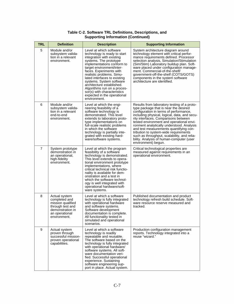
C-7
Table C-2. Software TRL Definitions, Descriptions, and Supporting Information (Continued)
TRL Definition Description Supporting Information
5 Module and/or subsystem valida-tion in a relevant environment.
Level at which software technology is ready to start integration with existing systems. The prototype implementations conform to target environment/inter-faces. Experiments with realistic problems. Simu-lated interfaces to existing systems. System software architecture established. Algorithms run on a proces-sor(s) with characteristics expected in the operational environment.
System architecture diagram around technology element with critical perfor-mance requirements defined. Processor selection analysis, Simulation/Stimulation (Sim/Stim) Laboratory buildup plan. Soft-ware placed under configuration manage-ment. Commercial-of-the-shelf/ government-off-the-shelf (COTS/GOTS) components in the system software architecture are identified.
6 Module and/or subsystem valida-tion in a relevant end-to-end environment.
Level at which the engi-neering feasibility of a software technology is demonstrated. This level extends to laboratory proto-type implementations on full-scale realistic problems in which the software technology is partially inte-grated with existing hard-ware/software systems.
Results from laboratory testing of a proto-type package that is near the desired configuration in terms of performance, including physical, logical, data, and secu-rity interfaces. Comparisons between tested environment and operational envi-ronment analytically understood. Analysis and test measurements quantifying con-tribution to system-wide requirements such as throughput, scalability, and relia-bility. Analysis of human-computer (user environment) begun.
7 System prototype demonstration in an operational, high-fidelity environment.
Level at which the program feasibility of a software technology is demonstrated. This level extends to opera-tional environment prototype implementations, where critical technical risk functio-nality is available for dem-onstration and a test in which the software technol-ogy is well integrated with operational hardware/soft-ware systems.
Critical technological properties are measured against requirements in an operational environment.
8 Actual system completed and mission qualified through test and demonstration in an operational environment.
Level at which a software technology is fully integrated with operational hardware and software systems. Software development documentation is complete. All functionality tested in simulated and operational scenarios.
Published documentation and product technology refresh build schedule. Soft-ware resource reserve measured and tracked.
9 Actual system proven through successful mission-proven operational capabilities.
Level at which a software technology is readily repeatable and reusable. The software based on the technology is fully integrated with operational hardware/ software systems. All soft-ware documentation veri-fied. Successful operational experience. Sustaining software engineering sup-port in place. Actual system.
Production configuration management reports. Technology integrated into a reuse “wizard.”

C-8
C.1.3 Additional TRL Definitions
Table C-3 provides additional TRL definitions.
Table C-3. Additional Definitions of TRL Descriptive Terms
Term Definition
Breadboard Integrated components that provide a representation of a system/subsystem and that can be used to determine con-cept feasibility and to develop technical data. Typically configured for laboratory use to demonstrate the technical principles of immediate interest. May resemble final sys-tem/subsystem in function only.
High Fidelity Addresses form, fit, and function. A high-fidelity laboratory environment would involve testing with equipment that can simulate and validate all system specifications within a laboratory setting.
Low Fidelity A representative of the component or system that has limited ability to provide anything but first-order information about the end product. Low-fidelity assessments are used to provide trend analysis.
Model A functional form of a system, generally reduced in scale, near or at operational specification. Models will be suffi-ciently hardened to allow demonstration of the technical and operational capabilities required of the final system.
Operational Environment Environment that addresses all the operational requirements and specifications required of the final system to include platform/packaging.
Prototype A physical or virtual model used to evaluate the technical or manufacturing feasibility or military utility of a particular technology or process, concept, end item, or system.
Relevant Environment Testing environment that simulates both the most important and most stressing aspects of the operational environment.
Simulated Operational Environment Either (1) a real environment that can simulate all the opera-tional requirements and specifications required of the final system or (2) a simulated environment that allows for testing of a virtual prototype. Used in either case to determine whether a developmental system meets the operational requirements and specifications of the final system.
C.2 Assessing Hardware CTEs
Applying the TRL definitions to assess the maturity of hardware technologies
appears to be straightforward. For a particular technology, the level of technical readiness
that best describes the accomplishments and evidence per the TRL definitions should be
assigned. In practice, this approach is more difficult than it appears to be because the
TRL definitions often fail to account for all real-life situations.
TRL definitions involve several characteristics. One characteristic is the scale of
the application. It ranges from device to component, subsystem, and system. Another
characteristic is the environment. It includes the laboratory, mathematical models,
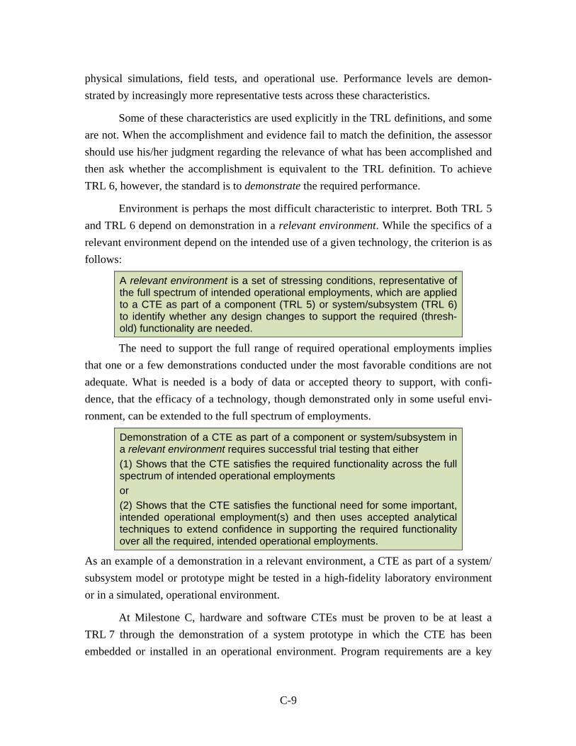
C-9
physical simulations, field tests, and operational use. Performance levels are demon-
strated by increasingly more representative tests across these characteristics.
Some of these characteristics are used explicitly in the TRL definitions, and some
are not. When the accomplishment and evidence fail to match the definition, the assessor
should use his/her judgment regarding the relevance of what has been accomplished and
then ask whether the accomplishment is equivalent to the TRL definition. To achieve
TRL 6, however, the standard is to demonstrate the required performance.
Environment is perhaps the most difficult characteristic to interpret. Both TRL 5
and TRL 6 depend on demonstration in a relevant environment. While the specifics of a
relevant environment depend on the intended use of a given technology, the criterion is as
follows:
A relevant environment is a set of stressing conditions, representative of the full spectrum of intended operational employments, which are applied to a CTE as part of a component (TRL 5) or system/subsystem (TRL 6) to identify whether any design changes to support the required (thresh-old) functionality are needed.
The need to support the full range of required operational employments implies
that one or a few demonstrations conducted under the most favorable conditions are not
adequate. What is needed is a body of data or accepted theory to support, with confi-
dence, that the efficacy of a technology, though demonstrated only in some useful envi-
ronment, can be extended to the full spectrum of employments.
Demonstration of a CTE as part of a component or system/subsystem in a relevant environment requires successful trial testing that either
(1) Shows that the CTE satisfies the required functionality across the full spectrum of intended operational employments
or
(2) Shows that the CTE satisfies the functional need for some important, intended operational employment(s) and then uses accepted analytical techniques to extend confidence in supporting the required functionality over all the required, intended operational employments.
As an example of a demonstration in a relevant environment, a CTE as part of a system/
subsystem model or prototype might be tested in a high-fidelity laboratory environment
or in a simulated, operational environment.
At Milestone C, hardware and software CTEs must be proven to be at least a
TRL 7 through the demonstration of a system prototype in which the CTE has been
embedded or installed in an operational environment. Program requirements are a key

C-10
source for defining the operational environment. The assessment of TRL 7, as opposed to
TRL 6, involves a shift in the scale of what is being demonstrated. Whereas TRL 6
focuses on the demonstration of a CTE that has been embedded or installed in a repre-
sentative model or prototype of a subsystem/system, TRL 7 entails the demonstration of a
CTE that has been embedded or installed in a prototype of the planned operational sys-
tem. This still leaves open the issue of environment.
While the specifics of an operational environment depend on the intended use of a
CTE, a generic description of an operational environment and what it demonstrates are as
follows:
An operational environment is a set of operational conditions, representa-tive of the full spectrum of operational employments, which are applied to a CTE as part of a system prototype (TRL 7) or actual system (TRL 8) in order to identify whether any previously unknown or undiscovered design problems might impact required (threshold) functionality.
Demonstration of a CTE as part of a system prototype in an operational environment requires successful testing that either
(1) Shows that the CTE satisfies the required functionality across the full spectrum of operational employments
or
(2) Shows that the CTE satisfies the functional need for important, opera-tional employment(s) and then uses accepted analytical techniques to extend confidence in supporting the required functionality over all the required operational employments.
As an example of a demonstration in an operational environment, a CTE as part of a sys-
tem prototype might be installed in an aircraft or vehicle, which is then tested in the real-
world operational conditions of a test-bed or test range facility.
C.2.1 Aircraft
Aircraft are likely to have CTEs in aerodynamic configuration and controls, air-
frame structure and aeroelasticity, flight control systems, and propulsion. In addition,
rotary-wing aircraft have CTEs in power transfer, rotor hub, and blades. CTEs could also
be factors in mission equipment, secondary power, environmental control, and other sys-
tems, depending on the aircraft’s missions. A variety of methods and facilities are used to
demonstrate these different technologies.

C-11
For example, demonstrations such as analysis, computational fluid dynamics
(CFD) investigations, wind tunnel tests2, and flight tests are normally used for the aero-
dynamic configuration and controls. When aerodynamic configurations indicate large
departures from existing aircraft, free-flight models (manned or unmanned) are some-
times used. Similarly, a variety of methods and facilities are used for airframe, flight
control, and other aeronautical disciplines.
C.2.2 Ground Vehicles
Most new military vehicle concepts/systems can be expected to involve CTEs.
Combat and tactical vehicles face new requirements driven by new threats and new or
extended performance needs of operational forces. Utility and general-purpose vehicles—
many of which are adapted versions of commercial vehicles—also can be required to pro-
vide special performance characteristics that exploit new technologies or novel applica-
tion of existing technologies.
The automotive features of any class of military vehicles are likely to exploit
critical technologies in propulsive power, drive trains, platform stability, suspension sys-
tems, and endurance. Demonstration of critical technology efficacy requires various
means of test, analysis, and verification. In most cases, these tests and analyses are
unique to the military environment.
The protection requirements and features of combat and tactical vehicles are
unique aspects driven by combat environments. CTEs should be anticipated in vehicle
integrated passive protection against diverse weapon and munitions threats. Similarly, as
threats increase and become more sophisticated, CTEs appear that have reactive (e.g.,
explosive armor) or active (e.g., detection and attack of threat munitions) aspects. Evalua-
tion of the maturity of these technologies is often made by developing extensions to
existing analysis and test capabilities.
C.2.3 Missiles and Guided Weapons
The development program for a missile or other guided weapon is quite different
from that of a “platform” vehicle, and the program for a solid propellant rocket is differ-
ent from that of a liquid propellant rocket. Most military missiles have structure, propul-
sion, guidance, flight control, and payload. Each of these systems comprises numerous
2 Often with a variety of scale models tested in several different wind tunnels to obtain data for different flight conditions and mission phases.

C-12
elements that must function together to meet the objectives of the system, and any of
these elements can depend upon CTEs. To assess the maturity of these critical technolo-
gies, issues that should be considered in performance demonstrations include how the test
environments compare with the real environments and how the performance exposes
what is required.
Missile structural integrity and flight control are highly interdependent. Structural
bending modes, placement of accelerometers, control system time constants, aerody-
namic loads and control moments, and reaction controls must work together to achieve
stable, controlled flight. Structural rigidity and inertial properties can first be computed
during computer-aided design (CAD) and confirmed by ground tests. Aerodynamics can
be determined by analysis and wind tunnel tests. High-fidelity, 6 degree of freedom
(DOF) simulations can represent the complete missile in its intended flight environment.
Components that are tested in hardware-in-the-loop (HWIL) simulations can reasonably
be considered to be TRL 4. If we assume that flight accelerations and vibrations are
important to the functioning of a component, testing that component while it is carried on
a surrogate missile could achieve TRL 5. After the components have been integrated into
a dynamically correct prototype missile and are flown, perhaps on a flight with pre-
programmed maneuvers, the components can be considered TRL 6 if the environment is
relevant for those components.
Missile guidance systems can include a variety of sensor types. Several types of
test environments are useful for particular types of sensors. These include anechoic
chambers for radars and other radio frequency (RF) systems, terrain tables for visual and
infrared (IR) detectors, towers overlooking tactical targets, captive carry on aircraft and
missiles, and free flight. The maturity associated with these sensors depends on the fidel-
ity of the relevant features of the environment and the fidelity of the test article when
compared with the final product. If a tower can provide the correct viewpoint and range
to a target and if motion is not important, perhaps a tower test of a prototype sensor can
be adequate to assess TRL 5. However, if motion is important, a captive carry test might
be necessary to achieve TRL 5. Since motion is almost always important to missile guid-
ance systems, captive carry for TRL 5 and demonstration on a prototype or surrogate
missile for TRL 6 are suggested as the norms.
For liquid fuel rockets, different items are important. Movement and metering of
fuel and oxidizer are considerations, and throttling or multiple starts and cooling of the

C-13
nozzle with fuel might be factors. Relevant conditions can include very low ambient
pressures and longitudinal and lateral accelerations that can be achieved only in flight.
Air-breathing rockets have the additional needs to establish inlet performance and
flammability limits over a wide range of Mach numbers and ambient pressures. Demon-
strations can include connected tests (inlet connected to an air source) to merit TRL 4and
free-flow tests including inlet, captive-carry, and free-flight tests to merit TRLs of 5, 5,
and 6, respectively, if the test articles of the free-flight tests are functionally representa-
tive prototypes.
C.2.4 Ships and Ship Systems
Ships are likely to have CTEs in hydrodynamic hull form, materials and struc-
tures, propulsion, drag reduction, and motion controls. Ship systems, such as sensors
(radar/sonar), weapons (torpedoes/missiles), hotel (waste disposal/desalination/material
movement), and aircraft interfaces (elevators), will require some additional CTEs. Ships
also have CTEs related to survivability, such as signatures, countermeasures, and intact
and damaged stability. A wide variety of methods and facilities are used to demonstrate
these different technologies.
Ships are usually large and complex; therefore, prototyping of a complete system,
such as a new hull form, is expensive and time consuming. The types of demonstrations
used normally for ship hull-form technologies include analysis, CFD investigations,
towing tank model scale tests, and land-based subsystem tests. For ship configurations
that represent large departures from the existing base of knowledge, full-scale prototypes
are usually needed.
Similarly, a variety of methods and facilities are used for structures and materials,
motion control, and other ship-related disciplines. For ship-based missile systems, see
Section C.2.3. Torpedo development would follow an approach similar to that of a mis-
sile system. The technologies of active drag reduction are treated similar to those of a
propulsion subsystem, such as a new propeller, and would follow the propulsion
approach. Passive drag reduction systems, such as hull shaping, are treated similar to the
hull form development approach.
C.2.5 Hardware for IT Applications
This example describes the approach for assessing the technical readiness of
hardware CTEs used in IT applications.

C-14
Effective Information Displays for Soldiers on the Battlefield
Infantry soldiers on the battlefield operate in an extremely demanding environ-
ment. While soldiers are expected to carry the equivalent of a laptop computer, the form
and fit of a conventional laptop is awkward. This CTE example is concerned with the
display technology of an integrated computer system that has an ergonomic fit and form
for infantry soldiers.
A high-tech monocle (based on Microelectromechanical Systems (MEMS) tech-
nology)) to project images directly onto the retina has been selected.3 The military has
tested early prototypes of this technology. Commanders of Stryker vehicles have the
option of viewing the onboard battlefield computer with a helmet-mounted display
(HMD). Another prototype system has experimented with this technology to increase sit-
uational awareness by providing helicopter pilots a digital display of the battlespace.
The experience gained from testing the display with soldiers in Stryker vehicles
and with helicopter pilots provides a technical readiness of no higher than TRL 6 based
on evidence from these field trials. The operational environment of the infantry soldier is
quite different from the two tested applications. Achieving a TRL 7 or higher would
require that the display be tested in the infantry soldier’s operational environment.
C.3 Assessing Software CTEs
As in hardware systems, the definitions of TRLs as applied to software involve
several dimensions. At the application level are values of device, component, subsystem,
and system for hardware and algorithms, software components, software programs, and
software packages. Another dimension, discussed at length in Appendix B, includes the
environment (or application)—integration issues, laboratory user environment issues,
logical relationship issues, data environment issues, security environment issues, and pos-
sibly interface issues. Other system-wide dimensions include obsolescence, scalability,
and throughput and are usually expressed in terms of system-wide requirements, but the
hardware components often contribute to meeting these requirements. As in the hardware
TRLs, some of these terms are used explicitly in the TRL definitions, and some are not.
The combination of these dimensions determines any TRL. When the accomplishment
3 Such a system is expected to be more rugged than conventional approaches (e.g., to be able to be read in the daylight and to have higher resolution than a conventional display). Furthermore, because essen-tially all the light generated enters the eye, the device is extremely energy efficient and thereby reduces demand on the local power supply.

C-15
and the definition do not match, the assessor must use his/her judgment regarding the
relevance of what has been accomplished and ask whether the accomplishment is equiva-
lent to the TRL definition.
In assessing software’s technical readiness, one must be aware of the proper use
of the terms relevant environment and operational environment. Claiming technical rea-
diness in a relevant environment (TRL 5 or higher) requires a detailed architecture that
fully exposes all components and elements affecting the operation of the critical software
element. Claiming technical readiness in an end-to-end relevant environment (TRL 6 or
higher) requires evidence of performance on full-scale, realistic problems. Claiming tech-
nical readiness in an operational environment (TRL 7 or higher) requires evidence of the
acceptable performance of the software element under operational factors, including, for
example, system loading, user interaction, security, and realistic communications envi-
ronment (e.g., bandwidth, latency, jitter).
Brief examples estimating the level of technical readiness for software elements
follow.
C.3.1 Information Integration of Unstructured Data
This situation highlights CTE assessment considerations in programs that inter-
face with many semi-autonomous organizations at the information, data, and processing
levels but have little or no design influence within the organizations beyond the interface.
In such as system, eXtensible Markup Language (XML) can be used to access structured
and unstructured data.4 XML would describe unstructured data through XML schemas,
and data access would be provided via XQuery and XPath standards.
If the application were a mission planning system, several DoD-unique concerns
would have to be considered:
Because of the limited control over design and operation internal to the organization hosting the data sources, an increased emphasis would have to be placed on the inter-organization interface for delineating areas of
4 The data in a structured data source are strongly typed, and relationships are described by a schema. The data are organized in tables and accessed via a relational database. Structured Query Language (SQL) is supported for accessing information in the database. Unstructured data consists of practically everything else, including documents, images, data sets, field reports, and maps. While some of these unstructured data types are semi-structured, which can be exploited for organization and accessibility, these heterogeneous data sets have begun to be unified only recently. A query should transparently combine data from relational tables, the XML database, and data retrieved from external servers.

C-16
responsibility (i.e., functional allocation) and standards for representing data using XML.
The system needs to accommodate the restrictive nature of highly classified data sources while providing access to less classified and unclassified sources. For this system to be useful, the security model, along with its implementation, must successfully provide access while enforcing security policies in a manner that still allows for automated and efficient operation.
Although base standards have been issued for XQuery and XPath, it is not clear that they have achieved sufficient maturity for this application.
CTEs would be found in the XML data models and their interaction with XQuery,
in the interface definitions (including functional allocation among the organization), and
in the implementation of security policy. Without any documented, relevant DoD expe-
rience, a TRL of 4 is the highest level that should be assigned.
C.3.2 Distributed Resource Sharing
This example discusses CTEs associated with the capability to process, interpret, and
distribute an unprecedented quantity of data collected from sensor networks, overhead
assets, and other means of collecting technical data in a timely manner—a net-centric
warfare scenario. The technical approach will implement a grid service architecture that
is currently being developed in a consortium environment for coordinated resource
sharing and problem solving in a dynamic, multi-organizational setting.5
CTEs are mostly confined to the suitability and performance of the architecture in
a military environment. Specifically, concern involves accommodating DoD security
policy and performance over a network of limited bandwidth, including response to
unexpected events that cause resources to disappear temporarily (e.g., severance of a
communications link).
5 Storage, computational, and communication resources will be shared by providing standard, open, and general-purpose protocols and interfaces for capabilities, including authentication, authorization, resource discovery, and resource access. This capability includes direct and managed access to sensors, processors, software, communications bandwidth, storage, file systems, database, and servers. These resources can be used collectively on existing standard Web service components in a coordinated fashion to deliver negotiated QoS, relating, for example, to response time, throughput, availability, and security. The thrust is to provide a capability for dynamically establishing resource-sharing arrange-ments with any interested member and thus create something more than a plethora of balkanized, incompatible, non-interoperable distributed systems.
C-17
A highly promoted way of developing software and standards is through a con-
sortium that has wide participation from commercial, government, and academic organi-
zations. This approach is becoming accepted in the software and communications sectors
as a way to promote open standards and better accommodate user needs. In the present
example, grid technology has undergone continuous development for more than 10 years
and has resulted in several standards and software package releases. Through active par-
ticipation, the program intends to use the standards as they currently exist and influence
their evolution to accommodate currently unsatisfied needs.
Because the selected architecture has only established its viability in primarily
scientific and limited commercial domains, a TRL of no higher than 4 should be
assigned. Achieving a higher level of technical readiness is possible only in the context of
a detailed architecture and within a distributed military environment. For example,
achieving the required Quality of Service (QoS) level is critical to the viability of this
system. QoS is difficult—if not impossible—to assess accurately without an operational
system. The difficulty in assessing QoS arises because QoS degrades as a system is
stressed because of workload, dynamic reconfiguration, and component failures.
C.3.3 Autonomic Computing6
Dependence on IT systems during critical tactical operations places exceedingly
high requirements on reliability, availability, and security. A new strategy for increasing
IT system reliability and availability—while, at the same time, reducing dependence on
human intervention—incorporates an autonomic system to manage system operation
dynamically.7
6 Similar to the autonomic nervous system in humans, which frees our conscious brain from the burden of controlling low-level but vital functions and coping with deviations from normal operation (e.g., infection), an autonomic system as part of an IT system makes the IT system self-managing. The system becomes self-configuring, self-healing, self-optimizing, and self-protecting with minimal human intervention.
7 An autonomic system is implemented as a collection of interacting, automatically managed elements. These elements include hardware resources (e.g., storage, processing, or communications), software resources (e.g., application program, database, or operating system) or even other automatically managed IT systems. Each autonomic element is responsible for managing its own internal state and behavior. Through interacting with other automatically managed elements and the external world, the state of the system is driven toward consistency with the given goals.

C-18
Most of the technology required to build autonomic systems either does not exist
or exists at a research level/early prototype stage. Procurement of a fully autonomic sys-
tem is not technically viable at present. A TRL of 3 is the maximum assessment.
In the larger context of a well-defined, incremental approach for achieving a fully
autonomic capability, technology selection and evaluation should be focused on the capa-
bilities required for the current increment.8 The current strategy calls for evolving the
system though five increments (basic, managed, predictive, adaptive, and autonomic) that
progress from manually managed to automatically managed.
As an example, consider a program undergoing the development of its second
increment, which focuses on consolidation/presentation of state and performance data
through management tools.9 The software technology for functions of consolidation/
presentation is available and has been demonstrated to operate in a relevant environment
but not on a full-scale problem. Hence, the evidence will likely support a TRL of 5.
C.3.4 Radio Frequency Identification (RFID) Tags for Material Assets Management
Management of military supplies and equipment is exceedingly complex because
current inventory accounting systems are outdated, have limited interoperability, and are
implemented using poorly documented software. Knowing the current status of material
assets (e.g., current location, expected date of delivery for new assets, condition, and
ownership) reduces costs and improves capability.
RFID tags provide automatic identification of tagged assets as they pass through
locations equipped with interrogators. The military has used selective RF tagging of large
or expensive items for many years. However, as spurred by commercial organizations’
(e.g., Wal-Mart) management of their supply chain, RFID tagging will reach the point
where tagging practically all levels of material objects becomes technically and economi-
cally possible. Furthermore, not only will the tags identify the object type, but they can
also encode item-specific information, such as expiration date and lot number.
In the near future, DoD will be in a position to use a commercially proven tech-
nology with an inherently low technical risk. While this will certainly be true for several
8 The designer is responsible for selecting and developing technologies that naturally build toward future increments, which is not a consideration of technical readiness for the current increment.
9 The first increment defined and collected the data that are being consolidated.

C-19
common technology issues (e.g., the cost of tags and good readability by fixed interroga-
tors), military IT systems for collecting, processing, and using RFID tags are expected to
face many technical challenges. For example,
Knowing where the object is now and not where it was when the RFID tag was last read. Knowing an object’s whereabouts requires integrating tag information with the in-transit visibility (ITV) server. Other asset manage-ment systems that will need to interoperate with the RFID system include the Government Freight Management (GFM) system, the Global Air Transpor-tation Execution System (GATES), the Surface Transportation Management System (STMS), and the Movement Tracking System (MTS).
Objects tagged at multiple levels. If objects are tagged at multiple levels (e.g., the item itself, a box of items, a pallet of boxes, a shipping container housing the pallet, and so forth), not all tags will necessarily be interrogated at the same time. As the contents of shipping containers get rearranged and distributed and the pallets get broken down, mechanisms and procedures must be in place to determine the whereabouts of the material assets.
Interrogators. RFID only works when interrogators are in place to read the tags. Since deployment destinations are not always known in advance, either interrogators must be in place and operational before tagged assets are moved or a way to accommodate a loss of contact has to be developed.
While the answers to these problems do not appear to require new technology as
part of the solution, they do require a careful consideration of interactions, interoperabil-
ity with other systems, and sensible use of the RFID capability. Until systems have been
developed and real-world experience has been gained, a TRL of 5 or less is appropriate.
In addition, RFID tagging presents other technical challenges. DoD will use RFID
tags and receptors in some extreme environmental conditions in which many commercial
firms do not have to function. Potential wireless security concerns also exist if sensitive
material is being tracked. If a technology has only been demonstrated in low-fidelity con-
ditions with respect to the eventual environment (e.g., a laboratory environment or sig-
nificantly less-stressing one), a TRL of 4 is more appropriate.
C.3.5 Assessing Software CTEs in the Security Environment
The requirements that define the security environment are derived from both the
program-specific and more general requirements. The more general requirements include
items such as Department of Defense Instruction (DoDI) 8500.2, Information Assurance
(IA) Implementation; National Security Agency (NSA) certification levels; the Health

C-20
Insurance Portability and Accountability Act; and Homeland Security Presidential Direc-
tive 12 (HSPD 12), Policy for a Common Identification Standard for Federal Employees
and Contractors. The evolving nature of the cyber threat required the Independent
Review Team (IRT) to maintain up-to-date awareness of applicable statutes, policies, and
directives that govern the system under evaluation.
Any assessment of software CTEs must consider performance under duress (i.e.,
how the IT system will respond to threats). At a minimum, an analytic prediction of CTE
robustness under duress is required. For technologies that provide security, an assessment
under more adversarial conditions is required. Detailed planning of the assessment
depends critically on three items:
1. The nature of the CTE—both the technical approach and the nature of the mission influence the required assessment
2. Cost
3. Consideration of operational security, which influences the testing that can be done (especially for sensitive systems with many interfaces).
The Milestone B TRA should assess these areas for the relevant environment. The Mile-
stone C TRA requires detailed assessments in the operational environment.
Since implementation is such an important part of making an IT system secure,
the definition of TRL 6 for software must be applied properly. The supporting informa-
tion for software TRL 6 includes well-understood data on scalability and prototyping and
implies that a design has been built and tested. A key notion of software TRL 6 that dif-
ferentiates it from TRL 5 is that the software architecture that supports TRL 5 has been
implemented at TRL 6.
To illustrate the type of demonstration needed to establish the maturity of a DoD
IT system CTE under duress and stain, consider two examples:
1. A medical IT system designed to track specialized medical stocks
2. An identity establishment IT system designed to attribute unique identities to person or non-person entities for allowing access to DoD IT services.
The engineering feasibility of the medical system CTEs can be established by
demonstrating an ability to harvest and send data. While the medical system may not play
a direct role at the tactical edge, duress and strain still play a role in demonstrations at
TRL 6 and TRL 7. At TRL 6, sufficient testing must be accomplished to show that the
C-21
system will scale to handle the load implied or specified by the requirements. Assessing
scalability is an example of including a strain in the relevant environment.
The medical IT system may also fail because of a cyber attack. This failure could
result in the disruption of the logistics chain or merely provide an entry point for an
adversary. Such a logistics system may not have specific information assurance (IA)
requirements. The formal program requirements may only refer to general DoD regula-
tions or Global Information Grid (GIG) guidance. Nevertheless, the IA requirement must
be outlined. The TRA at Milestone B should provide a train of logic that explains how
the program will meet IA requirements when it is operational. This train of logic must go
beyond asserting adherence to DoD regulations and directives. It must also include a des-
cription of the system’s intended interfaces and external dependencies and a discussion of
the effect a cyber attack on CTE performance. For example, the medical IT system may
use a proprietary operating system for interoperability. Declaring the intention to use this
operating system and to apply security patches as required are part of a plan (albeit a
simple part) to meet IA requirements. If an adversary uses an unknown fault in that oper-
ating system to attack and the medical system is not fully interoperable with other sys-
tems, the consequence may be loss of capability.
At Milestone B, the TRA should also address the source of any security that other
systems provide an IT system and indicate the fall-back options as part of defining the
security environment. For example, the medical logistic system may need to communi-
cate with a tactical system that operates on the Secret Internet Protocol Router Network
(SIPRNet). If the medical program is required to develop a new technical solution to
achieve such an interface, it should be demonstrated and recorded in the medical system
TRA. If such an interface is not part of the medical program’s development responsibil-
ity, the expected interface—a key part of the operational environment—should be
described in sufficient detail so the performance of the medical program’s CTEs demon-
strated at Milestone B can be confidently extrapolated to the operational environment.
The TRA should address the consequences to the program’s CTEs if the interface were to
be attacked.
At Milestone C, the program must demonstrate the continued operation of CTEs
while under duress or provide a complete and convincing assessment of the performance
of its CTEs in a stressful environment. If a program is not required to explicitly defeat
cyber adversaries (as with the medical IT system), the program does not have to demon-
strate performance against an active adversary but must demonstrate how it interacts with

C-22
those systems that do provide defense against active adversaries. This demonstration
requires an assessment of the consequences to the program’s CTEs and mission assurance
if the cyber defenses are successfully breached. At Milestone C, a program must still also
demonstrate any of its own explicit IA requirements in an operational environment.
As an example of a second IT system, consider a system with direct security
responsibilities that enables access to DoD IT services by establishing one’s identity. In
this case, assessing CTE maturity may be simpler since the program has explicit require-
ments to defeat adversaries. The adversary must be considered at all stages of technology
development beyond TRL 3 (beyond TRL 3, a technology becomes associated with an
envisioned use). At TRL 6, the program must demonstrate the engineering feasibility of
its technical approach. For example, is the design able to function as intended against the
expected threat? Does it produce unique identity markers? For a system that has direct
security responsibilities, the Milestone B TRA must include a discussion of why the
demonstrated performance would be sufficient against an intelligent cyber adversary. For
example, the identity management program may include a digital signature algorithm and
associated protocols for implementation. At Milestone B (TRL 6), the program must
demonstrate the technical implementation of the algorithm and protocols. A discussion of
the expected operational environment must be included so that the demonstrated perfor-
mance can be extrapolated to an operational environment. For example, the chain of logic
that would allow extrapolation to an operational environment might include the strength
of the algorithms and protocols, the threat, a description of the program’s external inter-
faces, and an analysis of the consequences if a breach were to occur.
At Milestone C (TRL 7), the identity establishment program’s CTEs must be
demonstrated in an operational environment that includes an intelligent cyber adversary.
The security of the GIG is a survivability issue. Just as armor for a ground vehicle under-
goes ballistic testing, the GIG’s security features must also be demonstrated against
potential threats.
The common thread for assessing the medical logistics and identity establishment
programs is an “adversarial” assessment. As with the other program demonstrations, the
program office is responsible for funding this assessment. An adversarial test is critical
for several reasons: IT systems are inherently complex, the threat evolves rapidly and
non-deterministically, and effective security depends on the soundness of the design and
its implementation. The adversary should act as an “opposing force” attempting to sub-
vert the system. The adversarial test could be a “red-team” exercise, a table-top

C-23
discussion of vulnerabilities, an opposing force, or a combination of these elements. The
method used will depend on the nature of the CTEs, operational security, and cost. Since
the adversary is defined to be part of the operational environment, the IRT and the
Director, Research Directorate (DRD) should agree on the nature of the adversarial
assessment before the TRA has been completed. A consistent definition of the opera-
tional environment allows tests to be repeated. Since a long lead time may be associated
with adversarial exercises, it is important to begin this process early.
The adversarial tests should be designed to assess the CTEs of the program as
they were built but can also be designed to offer insight into variations of design or
implementation. The measure of success will be derived from program requirements.
Before the tests are conducted, the IRT should develop objective standards for success
(independently of anyone acting as the adversary), based on explicit and implicit program
requirements and the intended mission. For example, a CTE may have an explicit
requirement for throughput in a well-described threat scenario. If the throughput does not
meet the requirement, the demonstration is considered a failure. Implicit quantitative
requirements for CTEs can be treated in the same manner. Qualitative assessments
require the IRT to compare requirements to the mission before adopting success criteria.
For example, the medical IT system described previously may fail to detect that it has
been compromised and may pass malicious software to external sources. This situation is
not necessarily a failure of the adversarial demonstration for the CTEs. If no requirement
existed for intrusion detection and the CTEs’ performance is unaffected, the IRT may
have established this condition as a success. This would be excellent information to
record in the TRA (and provide to the programs that interface with the medical system).
Alternatively, the adversarial test might reveal that the chosen proprietary operating sys-
tem has many unknown security flaws that could be exploited to totally disable all the
CTEs. The IRT may have established as a success criterion that the operating system
have no more expected flaws than another operating system of similar complexity. When
comparing the explicit requirement for the medical system’s availability, the ease of
access to the operating system, and the known threat, the IRT is justified in claiming that
all the CTEs do not perform in the operational environment.

D-1
Appendix D.
Amplifying Technology Readiness
Assessment (TRA) Guidance for Ships

D-3
Ship and ship system acquisitions are different. Some of the most important dis-
tinctions are listed below. Each item on the list, while not common in other systems, may
not apply uniquely to ships. However, when all the items are taken in combination, ships
can be differentiated from all other systems that the Department of Defense (DoD)
acquires.
Complexity. A large number of the ship’s systems must interact with one another, and the shipbuilding process may last 4 years or more from the time that construction is authorized. Most other systems take less time. The com-plexity is compounded because each ship class has only a small number of ships, typically ranging from one to a few dozen, and each ship has a high unit cost. Ships can also have significantly longer service life cycles than other systems—carriers on the order of 50 years.
Design issues. The designs for the ship mission-oriented systems are modu-larly related to the ship’s overall hull, mechanical, and electrical (HM&E) design. This design must provide adequate space, weight, and power allow-ances and interfaces for the mission systems. Other than that, the designs can proceed somewhat independently. For most other systems, the designs are much more integrated, typically because of space, weight, and power con-straints that are normally not as critical for ships.
Safety and survivability issues. These important design considerations must be addressed early in the ship’s life cycle. Navy ships must be seaworthy under all sea and weather conditions.
Ship prototyping. This type of modeling (especially full-scale prototyping) is seldom done because it is expensive and takes a long time to complete. Simulation may not be a workable alternative because trying to validate simulations without a nearly full-scale model of the ship are difficult.
These differences are addressed in Department of Defense Instruction (DoDI)
5000.02. Ship milestones are not the same as those for other systems. Program initiation
for ships begins at Milestone A, while, for most other systems, program initiation is at
Milestone B and, in some cases, Milestone C.
The Technology Development phase, however, serves the same purpose for all
programs. All technologies intended for use in the program should be mature and should
have been through a successful demonstration in a relevant environment at the start of
full system design (i.e., before Milestone B). The lead ship in a class is normally autho-
rized at Milestone B. The associated contract for the lead ship usually contains options to
build a small number of additional ships.
D-4
The procurement of ships beyond the initial Milestone B contract is authorized in
a program review. For most ship programs, the Navy has the decision authority. A single
program review will normally lead to a contract for one additional ship, with options for a
few more.
Technology Readiness Assessments (TRAs) are required at Milestone A (program
initiation), Milestone B, and all program reviews. Although establishing a critical tech-
nology Integrated Product Team (IPT) to review and update the Critical Technology
Element (CTE) list continuously is a good idea for all programs, it is especially important
for the ship program office. As each CTE is identified, the IPT should also define the
relevant environment and identify the evidence required to support Technology Readi-
ness Level (TRL) 6. A best practice is to keep the Director, Research Directorate (DRD)
informed of new CTEs identified during the Technology Development phase.
No absolute maturity requirement is needed for CTEs at Milestone A. However,
baseline design plans that include a technology less than TRL 4 (component and/or
breadboard validation in a laboratory environment) at Milestone A are risky. A technol-
ogy that is just TRL 3 (analytical and experimental critical function and/or characteristic
proof of concept) at Milestone A is unlikely to be successfully matured to TRL 6 during
the Technology Development phase.
All CTEs for the lead ship and optional ships that are part of the lead ship contract
should be demonstrated in a relevant environment (TRL 6) at Milestone B so that the
Milestone Decision Authority (MDA) can make the certification required by Title 10
United States Code (U.S.C.) 2366b. For CTEs on the mission systems, either a land-
based test or a test on another ship is the preferred for evidence of maturity. Under some
circumstances, a high-fidelity simulation may be acceptable. Although HM&E CTEs are
somewhat unusual, a ship prototype should be used to conduct the comprehensive testing
needed to support certification. The scale of the prototype depends on what is needed to
ensure that the demonstration is sufficiently rigorous.
Contrary to frequent past practice, the baseline design for the ships on the lead
ship contract should include only mature technologies. More advanced or more capable
CTEs that the program manager (PM) would like to incorporate into the system may be
available; however, such CTEs should not be included in the baseline design if they are
immature—even if these CTEs have essential characteristics called out by the system
requirements. Similarly, if the motivation for the immature CTE is cost saving rather than
D-5
performance enhancement, the CTE should not be included in the baseline design.
Instead, Milestone B should be deferred until a sufficient level of technology maturation
has been achieved.
These new practices are not designed to foster highly conservative, risk-adverse
approaches for ship PMs. The PM should prepare maturation plans for such “preferred”
CTEs if these CTEs can be matured and included in the design before the Critical Design
Review (CDR). These plans should include an assessment of the current TRL and pro-
vide a schedule of the tests and results needed to demonstrate maturation to TRL 6. The
maturation plans should be consistent with the Systems Engineering Plan (SEP) and the
Test and Evaluation Master Plan (TEMP). Furthermore, the plans should indicate when
TRL 6 must be demonstrated so that the insertion plans will not disrupt the Integrated
Master Schedule (IMS). When maturation plans have been developed for preferred CTEs,
the Acquisition Decision Memorandum (ADM) should give explicit permission for the
parallel development process and require DRD approval before inserting these plans into
the program. This process implies a need for extensive collaboration between the Science
and Technology (S&T) community that is trying to mature the technology and the pro-
gram office that is trying to minimize the rework associated with changes to the designs
and drawings. Carefully managed Technology Transition Agreement (TTAs) and transi-
tion plans will facilitate communication.
A process similar to the one used at Milestone B should also be followed for the
TRAs at subsequent program reviews.

E-1
Appendix E. Biomedical Technology Readiness Levels (TRLs)
E.1 Background ......................................................................................................... E-3
E.2 The FDA Regulatory Process ............................................................................ E-17
E.2.1 Pharmaceuticals ................................................................................... E-17 E.2.2 Medical Devices ................................................................................... E-18
E.3 Web Sites ........................................................................................................... E-19
E.4 Additional Information ...................................................................................... E-19
Glossary for Appendix E ............................................................................................. E-21
E-3
Note: Medical-related items require Technology Readiness Level (TRL) definitions and descriptions that are appropriate to the technologies upon which they are based and that account for the statues and regulations that govern their development and use. In recog-nition of these factors, the United States Army Medical Research and Materiel Command (USAMRMC) took the initiative to establish appropriate definitions, descriptions, and processes in the context of military medical research and development (R&D) and Food and Drug administration (FDA) statutory and regulatory requirements. This appendix provides the results of their effort. E.1 Background
Department of Defense (DoD) policy mandates the use of U.S. FDA-approved products for force health protection,1 and the USAMRMC has always adhered to the regulatory requirements of the FDA for its studies of drugs, biologics, and devices in humans. To ensure compliance with the clinical phases of the FDA-regulated process and to reduce technological risk, the USAMRMC developed and recently updated their gen-eral guidelines for assigning TRLs to drug, vaccine, and medical device development programs.2 These guidelines are not considered absolutes, and characterization of activi-ties associated with TRLs can and does vary at times.
The science and technology (S&T) and acquisition program managers (PMs) work together in exercising discretion in the selection, progression, and timing of specific activities to be accomplished in the attainment of particular TRLs. Such flexibility and tailoring are needed to align the TRL decision criteria appropriately with the maturation and risk characteristics of a particular technology, including consideration of the associ-ated investment strategy and transition procedures that may vary among PMs.
1 For example, Department of Defense Directive (DoDD) 6200.2, Use of Investigational New Drugs for
Force Health Protection, August 1, 2000, or Health Affairs Policy 95-011, Tri-Service Pharmacy Pol-icy Guidance, July 26, 1995.
2 Biomedical Technology Readiness Levels (TRLs), prepared for the Commander, U.S. Army Medical Research and Materiel Command, under Contract DAMD17-98-D-0022, Science Applications International Corporation, 3 June 2003.
E-4
When transitioning from technology development to product development, the risks are greater if the TRL of a Critical Technology Element (CTE) is low. For medical technologies, risk reduction is not linear across TRLs. The rate of risk reduction remains very low until very late. Historically, FDA-regulated products, such as vaccines, do not achieve significant risk reduction (i.e., greater than 50%) until completion of Phase 3 clinical trials and approval of a biologics license application by the FDA (TRL 8). Indus-try’s experience is that only one in four vaccines going into Phase 3 trials is licensed. Similarly, whereas technology maturation is commonly perceived as a sequential contin-uum of activities from basic research, through development, to production and deploy-ment, the evolution of the TRL for a biomedical CTE may not be sequential, especially in those cases where FDA anchors are undefined. In cases of success or failure, the incre-mental change in the level of technology readiness may be greater than a single TRL. For example, upon successful completion of a pivotal study, biomedical information readi-ness levels may move from TRL 3 or 4 to TRL 9.
Biomedical TRL descriptions provide a systematic way for the S&T community to assess and communicate to the Milestone Decision Authority (MDA) the maturity level of a particular technology or combination of technologies and the maturity neces-sary for successful product development. This appendix provides equivalent TRL descriptions applicable to biomedical technologies in four categories:
1. Pharmaceutical (i.e., drugs) 2. Pharmaceutical (i.e., biologics/vaccines) 3. Medical Devices 4. Medical Information Management/Information Technology (IM/IT) and
Medical Informatics.
The TRLs for the first three categories have been developed from the DoD’s generic definitions, the applicable FDA regulatory process, and industry practices and experience with its R&D processes (discovery through manufacturing, production, and marketing). The last category includes elements of formal regulatory processes and logi-cal events in deriving comparable levels of maturity. Wherever practical, the USAMRMC intends to use external anchors such as “FDA events” to define each TRL decision criterion. Furthermore, activities described as occurring between successive TRL decision criteria are intended to exemplify the kinds of activities that routinely take place when maturation is sequential and stepwise. However, these examples are neither mandatory nor all inclusive.
Figure E-1 and Table E-1 build upon this work by providing examples of sup-porting information and documentation required to support the assignment of TRLs as the program progresses.
The proponent for this document is the Deputy for Research and Development: Commander, U.S. Army Medical Research and Materiel Command, ATTN: MCMR-ZA, 504 Scott Street, Fort Detrick, MD 21702-5012.

Figure E-1. TRLs in the Medical Materiel Regulatory Process
Note for Figure E-1: The TRL descriptions are not considered absolutes, and characterization of activities associated with TRLs can and does vary at times. The S&T and acquisition PMs work together in exercising discretion in the selection, progression, and timing of specific activities to be accom-plished, particularly with regard to TRL 5. Such flexibility and tailoring are needed to align the TRL decision criteria appropriately with maturation and risk characteristics of a particular technology, including consideration of the associated investment strategy and transition procedures that may vary among PMs.
TRL 1–3 TRL 4 TRL 5 TRL 6 TRL 7 TRL 8 TRL 9
• cGMP pilot lotproduction
• GLP safety andefficacy studies
• Endpoints of clinicalor surrogate efficacy
• Stability studiesinitiated
• Pre-IDE meeting andIDE prepared andsubmitted for ClassIII device
• 510(k) – preliminarydata suggest sub-stantial equivalencyto predicate device
• Generate/testhypotheses andexperimental designs
• Synthesize candidatecountermeasures
• Identify sites andmechanisms ofaction
• Device componentsand design identified
• Initial proof ofconcept
• Technologicalassessment require-ments identified
• Non-GLP formu-lation, dose, andpharmacokineticstudies
• Non-GLP safety andefficacy studies
• Assays/proceduresfor GLP/GCPstudies identified
• Device design his-tory file/reviewinitiated
U.S. Army Medical Research and Materiel Command
S&T
System Development and Production
Technology Readiness Assessment
• Pre-IND meeting• IND prepared and
submitted• Phase 1 clinical trials• Investigation of
Class III device inclinical trials
• Safety demonstrated• Production technology
demonstrated• 510(k) – data
demonstrate substa-tial equivalency topredicate device
• Phase 2 clinical trials• Investigation of Class III
prototype in clinicaltrials
• Safety and evidence ofefficacy demonstrated
• Final dose, dose range,and scheduleestablished
• Pre-Phase 3 meeting• Phase 3 clinical study
plan or surrogate testplan approved
• Class III device designvalidated and finalprototypes produced
• 510(k) – final prototypeproduced and tested
• Phase 3 clinical trials• Investigation of final
Class III prototype inclinical trials
• Safety and efficacydemonstrated
• Process validationcompleted
• Facility PAI completed• Pre-NDA/BLA/PMA
meeting• NDA/BLA/PMA/ 510(k)
prepared, submitted,and approved
• Marketing anddistribution
• Postmarketingstudies
• Postmarketingsurveillance
Prototype Maturation and DemonstrationProduction and
Distribution
Applied Research Translates Research toSolutions for Military Problems
Novel Conceptsand EmergingTechnologies
E-5

E-6
This page intentionally left blank.

General Note for Table E-1: The N1, N2, N3, and N4 superscripts refer to the Notes that are listed at the end of Table E-1.
Table E-1. Proposed TRLs for Medical Research, Development, Test, and Evaluation (RDT&E)
TRL 1 National Aeronautics and Space Administration (NASA)/Defense Acquisition Guidebook3 TRL Definition: Basic principles observed and reported
NASA/ Defense Acquisition
Guidebook TRL Description
USAMRMC Equivalent TRL Descriptions
Pharmaceutical (Drugs)N1, N2
Pharmaceutical (Biologics, Vaccines)N1, N2
Medical DevicesN3, N4 Medical IM/IT &
Medical Informatics Lowest level of technol-ogy readiness. Scientific research begins to be translated into applied research and develop-ment. Examples might include paper studies of a technology’s basic properties.
Lowest level of technology readiness. Mainte-nance of scientific awareness and generation of scientific and bioengineering knowledge base. Scientific findings are reviewed and assessed as a foundation for characterizing new technologies.
Lowest level of technology readiness. Mainte-nance of scientific awareness and generation of scientific and bioengineering knowledge base. Scientific findings are reviewed and assessed as a foundation for characterizing new technologies.
Lowest level of technology readiness. Mainte-nance of scientific awareness and generation of scientific and bioengineering knowledge base. Scientific findings are reviewed and assessed as a foundation for characterizing new technologies.
Hardware/software (HW/SW) system technology explored. Basic theories applied to IM/IT field suggesting promise.
TRL 1 Decision Criterion: Scientific literature reviews and initial market surveys are initiated and assessed. Potential scientific application to defined problems is articulated.
TRL 1 Decision Criterion: Scientific literature reviews and initial market surveys are initiated and assessed. Potential scientific application to defined problems is articulated.
TRL 1 Decision Criterion: Scientific literature reviews and initial market surveys are initiated and assessed. Potential scientific application to defined problems is articulated.
TRL 1 Decision Criterion: Identification of the potential medical solution to mission need. Medical Informatics data and knowledge representation issues are defined.
Supporting Information Supporting Information Supporting Information Reviews of open, published scientific literature concerning basic principles. Findings from mar-ket surveys of the open literature. Note: Privately funded research findings or market surveys are proprietary and rarely avail-able to the public.
Reviews of open, published scientific literature concerning basic principles. Findings from mar-ket surveys of the open literature. Note: Privately funded research findings or market surveys are proprietary and rarely avail-able to the public.
Reviews of open, published scientific literature concerning basic principles. Findings from mar-ket surveys of the open literature. Note: Privately funded research findings or market surveys are proprietary and rarely avail-able to the public.
3 The Defense Acquisition Guidebook (in revision) contains non-mandatory guidance on best practices, lessons learned, and expectations.
E-7

Table E-1. Proposed TRLs for Medical RDT&E (Continued)
TRL 2 NASA/Defense Acquisition Guidebook TRL Definition: Technology concept and/or application formulated NASA/
Defense Acquisition Guidebook
TRL Description
USAMRMC Equivalent TRL Descriptions
Pharmaceutical (Drugs)N1, N2
Pharmaceutical (Biologics, Vaccines)N1, N2
Medical DevicesN3, N4 Medical IM/IT &
Medical Informatics Invention begins. Once basic principles are observed, practical applications can be invented. Applications are speculative, and there may be no proof or detailed analysis to support the assumptions. Examples are limited to analytic studies.
Intense intellectual focus on the problem, with generation of scientific “paper studies” that review and generate research ideas, hypothe-ses, and experimental designs for addressing the related scientific issues.
Intense intellectual focus on the problem, with generation of scientific “paper studies” that review and generate research ideas, hypothe-ses, and experimental designs for addressing the related scientific issues.
Intense intellectual focus on the problem, with generation of scientific “paper studies” that review and generate research ideas, hypothe-ses, and experimental designs for addressing the related scientific issues.
HW/SW system invention begins. Overall system con-cepts are documented by flowcharting or other system-descriptive techniques.
TRL 2 Decision Criterion: Hypothesis(es) is generated. Research plans and/or protocols are developed, peer reviewed, and approved.
TRL 2 Decision Criterion: Hypothesis(es) is generated. Research plans and/or protocols are developed, peer reviewed, and approved.
TRL 2 Decision Criterion: Hypothesis(es) is generated. Research plans and/or protocols are developed, peer reviewed, and approved.
TRL 2 Decision Criterion: Identification of the potential medical solution to mission need. Medical Informatics data and knowledge representation issues are defined.
Supporting Information Supporting Information Supporting Information
Focused literature reviews are conducted and scientific discussions are held to generate research plans and studies that identify potential targets of opportunity for therapeutic interven-tion and to facilitate strategic planning. Sup-porting analyses provide scientific information and data for developing research proposals for filling in data gaps and identifying candidate concepts and/or therapeutic drugs. Documented by peer-reviewed approved protocol(s) or research plan(s).
Focused literature reviews are conducted and scientific discussions are held to generate research plans and studies that identify potential targets of opportunity for therapeutic interven-tion and to facilitate strategic planning. Sup-porting analyses provide scientific information and data for developing research proposals for filling in data gaps and identifying candidate concepts and/or therapeutic drugs. Documented by peer-reviewed approved protocol(s) or research plan(s).
Focused literature reviews are conducted and scientific discussions are held to generate research plans and studies that identify potential targets of opportunity for therapeutic interven-tion and to facilitate strategic planning. Sup-porting analyses provide scientific information and data for developing research proposals for filling in data gaps and identifying candidate concepts and/or devices. Documented by peer-reviewed approved protocol(s) or research plan(s).
E-8

Table E-1. Proposed TRLs for Medical RDT&E (Continued)
TRL 3 NASA/Defense Acquisition Guidebook TRL Definition: Analytical and experimental critical function and/or characteristic proof-of-concept NASA/
Defense Acquisition Guidebook
TRL Description
USAMRMC Equivalent TRL Descriptions
Pharmaceutical (Drugs)N1, N2
Pharmaceutical (Biologics, Vaccines)N1, N2
Medical DevicesN3, N4 Medical IM/IT &
Medical Informatics Active research and development is initiated. This includes analytical studies and laboratory studies to physically validate analytical pre-dictions of separate elements of the technol-ogy. Examples include components that are not yet integrated or representative.
Basic research, data collection, and analysis begin in order to test the hypothesis, explore alternative concepts, and identify and evaluate technologies supporting drug development. Initial synthesis of countermeasure candidate(s) and identification of their sites and mechanisms of action. Initial characterization of candidates in preclinical studies.
Basic research, data collection, and analysis begin in order to test hypothesis, explore alter-native concepts, and identify and evaluate criti-cal technologies and components supporting candidate biologic/vaccine constructs research and eventual development of a candidate countermeasure. Agent challenge studies are conducted to support models based on pre-sumed battlefield conditions. Research-scale process initiation and evaluation is conducted, as are studies to identify site(s) and mechan-ism(s) of action, potential correlates of protec-tion for vaccines, and initial physical/chemical characterization of constructs.
Basic research, data collection, and analysis begin in order to test hypothesis, explore alter-native concepts, and identify and evaluate com-ponent technologies. Initial tests of design concept and evaluation of candidate(s). Study endpoints defined. Animal models (if any) are proposed. Design verification, critical compo-nent specifications, and tests (if a system com-ponent or necessary for device test and evalua-tion (T&E)).
Separate elements of HW/SW system components are inves-tigated and developed but not yet integrated or representative.
TRL 3 Decision Criterion: Initial proof-of-concept for candidate drug constructs is demon-strated in a limited number of in vitro and in vivo research models.
TRL 3 Decision Criterion: Initial proof-of-concept for biologic/vaccine constructs is dem-onstrated in a limited number of in vitro and in vivo research models.
TRL 3 Decision Criterion: Initial proof-of-concept for device candidates is demonstrated in a limited number of laboratory models (may include animal studies).
TRL 3 Decision Criterion: Medical Informatics data and knowledge representation schema are modeled.
Supporting Information Supporting Information Supporting Information Documentation of the results of laboratory studies demonstrates preliminary proof-of-concept in in vitro and animal studies.
Documentation of the results of laboratory studies demonstrates preliminary proof-of-concept with candidate biologic/vaccine con-structs in in vitro and animal studies.
Documentation of the results of laboratory studies demonstrates preliminary proof-of-concept in laboratory models.
E-9
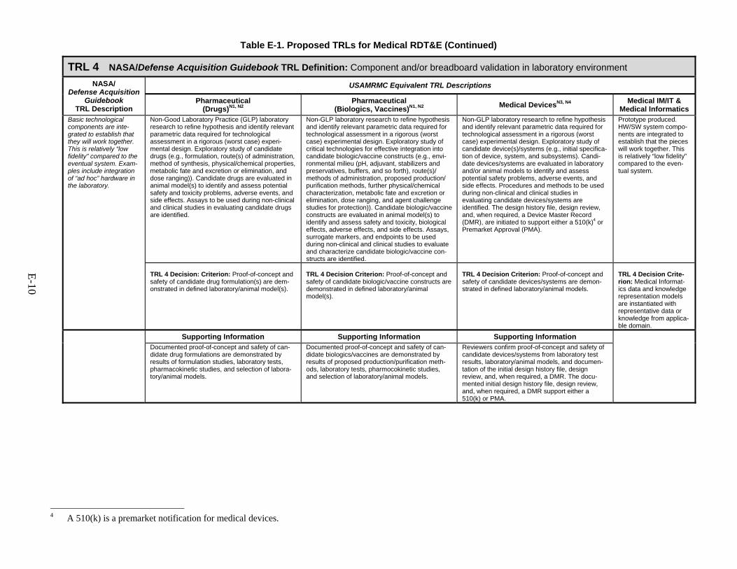
Table E-1. Proposed TRLs for Medical RDT&E (Continued)
TRL 4 NASA/Defense Acquisition Guidebook TRL Definition: Component and/or breadboard validation in laboratory environment
NASA/ Defense Acquisition
Guidebook TRL Description
USAMRMC Equivalent TRL Descriptions
Pharmaceutical (Drugs)N1, N2
Pharmaceutical (Biologics, Vaccines)N1, N2
Medical DevicesN3, N4 Medical IM/IT &
Medical Informatics Basic technological components are inte-grated to establish that they will work together. This is relatively “low fidelity” compared to the eventual system. Exam-ples include integration of “ad hoc” hardware in the laboratory.
Non-Good Laboratory Practice (GLP) laboratory research to refine hypothesis and identify relevant parametric data required for technological assessment in a rigorous (worst case) experi-mental design. Exploratory study of candidate drugs (e.g., formulation, route(s) of administration, method of synthesis, physical/chemical properties, metabolic fate and excretion or elimination, and dose ranging)). Candidate drugs are evaluated in animal model(s) to identify and assess potential safety and toxicity problems, adverse events, and side effects. Assays to be used during non-clinical and clinical studies in evaluating candidate drugs are identified.
Non-GLP laboratory research to refine hypothesis and identify relevant parametric data required for technological assessment in a rigorous (worst case) experimental design. Exploratory study of critical technologies for effective integration into candidate biologic/vaccine constructs (e.g., envi-ronmental milieu (pH, adjuvant, stabilizers and preservatives, buffers, and so forth), route(s)/ methods of administration, proposed production/ purification methods, further physical/chemical characterization, metabolic fate and excretion or elimination, dose ranging, and agent challenge studies for protection)). Candidate biologic/vaccine constructs are evaluated in animal model(s) to identify and assess safety and toxicity, biological effects, adverse effects, and side effects. Assays, surrogate markers, and endpoints to be used during non-clinical and clinical studies to evaluate and characterize candidate biologic/vaccine con-structs are identified.
Non-GLP laboratory research to refine hypothesis and identify relevant parametric data required for technological assessment in a rigorous (worst case) experimental design. Exploratory study of candidate device(s)/systems (e.g., initial specifica-tion of device, system, and subsystems). Candi-date devices/systems are evaluated in laboratory and/or animal models to identify and assess potential safety problems, adverse events, and side effects. Procedures and methods to be used during non-clinical and clinical studies in evaluating candidate devices/systems are identified. The design history file, design review, and, when required, a Device Master Record (DMR), are initiated to support either a 510(k)4 or Premarket Approval (PMA).
Prototype produced. HW/SW system compo-nents are integrated to establish that the pieces will work together. This is relatively “low fidelity” compared to the even-tual system.
TRL 4 Decision: Criterion: Proof-of-concept and safety of candidate drug formulation(s) are dem-onstrated in defined laboratory/animal model(s).
TRL 4 Decision Criterion: Proof-of-concept and safety of candidate biologic/vaccine constructs are demonstrated in defined laboratory/animal model(s).
TRL 4 Decision Criterion: Proof-of-concept and safety of candidate devices/systems are demon-strated in defined laboratory/animal models.
TRL 4 Decision Crite-rion: Medical Informat-ics data and knowledge representation models are instantiated with representative data or knowledge from applica-ble domain.
Supporting Information Supporting Information Supporting Information
Documented proof-of-concept and safety of can-didate drug formulations are demonstrated by results of formulation studies, laboratory tests, pharmacokinetic studies, and selection of labora-tory/animal models.
Documented proof-of-concept and safety of can-didate biologics/vaccines are demonstrated by results of proposed production/purification meth-ods, laboratory tests, pharmocokinetic studies, and selection of laboratory/animal models.
Reviewers confirm proof-of-concept and safety of candidate devices/systems from laboratory test results, laboratory/animal models, and documen-tation of the initial design history file, design review, and, when required, a DMR. The docu-mented initial design history file, design review, and, when required, a DMR support either a 510(k) or PMA.
4 A 510(k) is a premarket notification for medical devices.
E-10

Table E-1. Proposed TRLs for Medical RDT&E (Continued)
TRL 5 NASA/Defense Acquisition Guidebook TRL Definition: Component and/or breadboard validation in a relevant environment
NASA/ Defense Acquisition
Guidebook TRL Description
USAMRMC Equivalent TRL Descriptions
Pharmaceutical (Drugs)N1, N2
Pharmaceutical (Biologics, Vaccines)N1, N2
Medical DevicesN3, N4 Medical IM/IT &
Medical Informatics Fidelity of breadboard technology increases significantly. The basic technological compo-nents are integrated with reasonably realistic supporting elements so they can be tested in a simulated environment. Examples include “high-fidelity” laboratory inte-gration of components.
Intense period of non-clinical and preclinical research studies involving parametric data collection and analysis in well-defined systems, with pilot lots of candidate pharmaceuticals produced and further development of selected candidate(s). Results of research with pilot lots provide basis for a manufacturing process amenable to current Good Manufacturing Prac-tice (cGMP)-compliant pilot lot production. Conduct GLP safety and toxicity studies in animal model systems. Identify endpoints of clinical efficacy or its surrogate. Conduct stud-ies to evaluate the pharmacokinetics and phar-macodynamics of candidate drugs. Stability studies initiated.
Intense period of non-clinical and preclinical research studies involving parametric data collection and analysis in well-defined systems with pilot lots of candidate biologics/vaccines produced and further development of selected candidates. Research results support proposing a potency assay, proposing a manufacturing process amenable to cGMP-compliant pilot lot production, identifying and demonstrating proof-of-concept for a surrogate efficacy marker in an animal model(s) applicable to predicting protec-tive immunity in humans, and demonstrating preliminary safety and efficacy against an aero-sol challenge in a relevant animal model. Con-duct GLP safety and toxicity studies in animal model systems. Identify endpoints of clinical efficacy or its surrogate in animal models that may be applicable to predicting protective immunity in humans. Conduct studies to evalu-ate immunogenicity, as well as pharmacokinet-ics and pharmacodynamics when appropriate. Stability studies initiated.
Further development of selected candidate(s). Devices compared to existing modalities and indications for use and equivalency demon-strated in model systems. Examples include devices tested through simulation, in tissue or organ models, or animal models if required. All component suppliers/vendors are identified and qualified; vendors for critical components are audited for cGMP/Quality System Regulation (QSR) compliance. Component tests, compo-nent drawings, design history file, design review, and any DME are verified. Product Development Plan is drafted. Pre-Investi-gational Device Exemption (IDE) meeting is held with Center for Devices and Radiological Health (CDRH) for proposed Class III devices, and the IDE is prepared and submitted to CDRH. For a 510(k), determine substantially equivalent devices and their classification, validate func-tioning model, ensure initial testing is complete, and validate data and readiness for cGMP inspection.
First technical test of prototype. HW/SW system components are integrated, and realistic supporting elements are employed so that the system can be tested in a simulated environment. Actual interfaces to supporting systems are specified and development begins.
TRL 5 Decision Criterion: A decision point is reached at which it is determined that sufficient data on the candidate drug exist in the draft technical data package to justify proceeding with preparation of an Investigational New Drug (IND) application.
TRL 5 Decision Criterion: A decision point is reached at which it is determined that sufficient data on the candidate biologic/vaccine exist in the draft technical data package to justify pro-ceeding with preparation of an IND application.
TRL 5 Decision Criterion: IDE review by CDRH results to determine if the investigation can begin. For a 510(k), preliminary findings suggest the device will be substantially equivalent to a predicate device.
TRL 5 Decision Criterion: Medical Informatics data and knowledge representation mod-els are implemented as data and/or knowledge management systems and tested in a labo-ratory environment.
E-11
Table E-1. Proposed TRLs for Medical RDT&E (Continued)
TRL 5 NASA/Design Acquisition Guidebook TRL Definition: Component and/or breadboard validation in a relevant environment (Continued) Pharmaceutical
(Drugs)N1, N2 Pharmaceutical
(Biologics, Vaccines)N1, N2 Medical DevicesN3, N4
Supporting Information Supporting Information Supporting Information Reviewers confirm adequacy of information and data on candidate drug in a draft technical data package to support preparation of IND applica-tion. Documentation in the draft technical data package contains data from animal pharmacol-ogy and toxicology studies, proposed manufac-turing information, and clinical protocols for Phase 1 clinical testing.
Reviewers confirm adequacy of information and data on candidate biologic/vaccine constructs in draft technical data package to support prepa-ration of an IND application. Documentation in the draft technical data package contains data from animal pharmacology and toxicology studies, proposed manufacturing information, and clinical protocols suitable for Phase 1 clini-cal testing.
For investigation of a Class III device to begin in humans, the following are needed: (1) the FDA’s and sponsor’s summary minutes of pre-IDE meeting document agreements and general adequacy of information and data to support preparation and submission of IDE application and (2) an FDA letter acknowledging receipt of IDE by CDRH. The investigational plan (clinical trials) can begin after 30 days (barring a clinical hold from the FDA) or sooner if CDRH approves the IDE within 30 days. In the latter case, CDRH will provide written notification. The submitted IDE includes information regarding the sponsor, intended use of device, rationale for use of device, investigational plan, instruc-tions for use of device, labeling, and informed consent. For a 510(k) device, reviewers confirm prelimi-nary claim that the medical device appears substantially equivalent to a predicate device, the proposed classification is consistent with 21CFR860, there is a functioning model, and testing results support substantial equivalency.
E-12
Table E-1. Proposed TRLs for Medical RDT&E (Continued)
TRL 6 NASA/Defense Acquisition Guidebook TRL Definition: System/subsystem model or prototype demonstration in a relevant environment
NASA/ Defense Acquisition
Guidebook TRL Description
USAMRMC Equivalent TRL Descriptions
Pharmaceutical (Drugs)N1, N2
Pharmaceutical (Biologics, Vaccines)N1, N2
Medical DevicesN3, N4 Medical IM/IT &
Medical Informatics Representative model or prototype system, which is well beyond that of TRL 5, is tested in a relevant environment. Represents a major step up in a technology’s demonstrated readiness. Examples include testing a prototype in a high-fidelity laboratory envi-ronment or in a simu-lated operational environment.
Pre-IND meeting (Type B) held with the Center for Drug Evaluation and Research (CDER). IND application is prepared and submitted. Phase 1 clinical trials are conducted to demonstrate safety of candidate in a small number of humans under carefully controlled and intensely monitored clinical conditions. Evaluation of pharmacokinetic and pharmacodynamic data to support the design of well-controlled, scientifi-cally valid Phase 2 studies. Production technol-ogies are demonstrated through production-scale cGMP plant qualification.
Pre-IND meeting (Type B) held with the Center for Biologics Evaluation and Research (CBER). IND application is prepared and submitted. Phase 1 clinical trials are conducted to demon-strate safety of candidates in a small number of subjects under carefully controlled and intensely monitored clinical conditions. Evaluation of immunogenicity and/or pharmacokinetics and pharmacodynamics data to support design of Phase 2 clinical trials. Surrogate efficacy mod-els are validated.
Clinical trials are conducted to demonstrate safety of candidate Class III medical device in a small number of humans under carefully con-trolled and intensely monitored clinical condi-tions. Component tests, component drawings, design history file, design review, and any DMR are updated and verified. Production technology demonstrated through production-scale cGMP plant qualification. For 510(k), component tests, component drawings, design history file, design review, and any DMR are updated and verified. Manufac-turing facility is ready for cGMP inspection.
Advanced technical testing of prototype HW/SW system, to include interfaces to actual supporting systems, is con-ducted in a relevant or simu-lated operational environment. Out-product is final prototype.
TRL 6 Decision Criterion: Data from Phase 1 trials meet clinical safety requirements and support proceeding to Phase 2 clinical studies.
TRL 6 Decision Criterion: Data from Phase 1 clinical trials meet clinical safety requirements and support proceeding to Phase 2 clinical trials.
TRL 6 Decision Criterion: Data from the initial clinical investigation demonstrate that the Class III device meets safety requirements and support proceeding to clinical safety and effec-tiveness trials. For a 510(k), information and data demonstrate substantial equivalency to predicate device and support production of the final prototype and final testing in a military operational environment.
TRL 6 Decision Criterion: Medical Informatics data and knowledge management sys-tems are tested with target applications in a laboratory environment. Configuration management approach developed.
Supporting Information Supporting Information Supporting Information For Phase 1 Clinical Trials to begin, the following are needed: the FDA’s and sponsor’s summary minutes of pre-IND meeting document agreements and general adequacy of informa-tion and data to support submission of IND application. Review of the submitted IND appli-cation does not result in a FDA decision to put a clinical hold on Phase 1 clinical trials with the candidate drug. For entry into Phase 2 clinical trials, the results from Phase 1 clinical studies have to demon-strate safety of candidate drug. An updated IND application, amended with a new clinical pro-tocol to support Phase 2 clinical trials or a sur-rogate test plan and submitted to the FDA, documents the achievement of this criterion.
For Phase 1 Clinical Trials to begin, the following are needed: the FDA’s and sponsor’s summary minutes of pre-IND meeting document agreements and general adequacy of informa-tion and data to support submission of an IND application. Review of the submitted IND does not result in an FDA decision to put a clinical hold on Phase 1 clinical trials with the candidate biologic/vaccine. For entry into Phase 2 clinical trials, the results from Phase 1 clinical studies have to demon-strate safety of candidate biologic/vaccine. An updated IND, amended with a new clinical protocol to support Phase 2 clinical trials or surrogate test plan and submitted to the FDA, documents achieving this criterion.
Documentation from clinical study results shows the candidate device is safe. Changes to the investigational plan that require FDA approval (21CFR812.35) are submitted as a supple-mental IDE application to the FDA. For a 510(k), reviewers confirm adequacy of documented component tests, component drawings, design history file, design review, and any DMR to support claim of substantial equiva-lency and readiness for final testing in a military operational environment.
E-13
Table E-1. Proposed TRLs for Medical RDT&E (Continued)
TRL 7 NASA/Defense Acquisition Guidebook TRL Definition: System prototype demonstration in an operational environment
NASA/ Defense Acquisition
Guidebook TRL Description
USAMRMC Equivalent TRL Descriptions
Pharmaceutical (Drugs)N1, N2
Pharmaceutical (Biologics, Vaccines)N1, N2
Medical DevicesN3, N4 Medical IM/IT &
Medical Informatics Prototype near, or at, planned operational system. Represents a major step up from TRL 6, requiring demon-stration of an actual system prototype in an operational environment (e.g., in an aircraft, in a vehicle, or in space). Examples include testing the prototype in a test-bed aircraft.
Phase 2 clinical trials are conducted to demon-strate initial efficacy and capture further safety and toxicity data. Product activity (e.g., preliminary evidence of efficacy) is determined. Product final dose, dose range, schedule, and route of admini-stration are established from clinical pharmacoki-netic and pharmacodynamic data. Phase 2 clinical trials are completed. Data are collected, pre-sented, and discussed with CDER at pre-Phase 3 meeting (Type B) in support of continued drug development. Clinical endpoints and/or surrogate efficacy markers and test plans agreed to by CDER.
Phase 2 safety and immunogenicity trials are con-ducted. Product immunogenicity and biological activity (e.g., preliminary evidence of efficacy) are determined. Product final dose, dose range, schedule, and route of administration are estab-lished from vaccine immunogenicity and biologic activity and, when necessary, from clinical phar-macokinetics and pharmacodynamics data. Phase 2 clinical trials completed. Data are col-lected, presented, and discussed with CBER at pre-Phase 3 (or surrogate efficacy) meeting (Type B) in support of continued development of the biologics/vaccines. Clinical endpoints and/or surrogate efficacy markers and test plans agreed to by CBER.
Clinical safety and effectiveness trials are con-ducted with a fully integrated Class III medical device prototype in an operational environment. Continuation of closely controlled studies of effec-tiveness and determination of short-term adverse events and risks associated with the candidate product. Functional testing of candidate devices is completed and confirmed, resulting in final down-selection of prototype device. Clinical safety and effectiveness trials are completed. Final product design is validated, and final prototype and/or initial commercial scale device is produced. Data are collected, presented, and discussed with CDRH in support of continued device development.
For a 510(k), final prototype and/or initial commer-cial-scale device are produced and tested in a military operational environment.
Prototype HW/SW sys-tem is near or at planned operational system. Actual system prototype is demonstrated in an operational environment with end-users (first cut user test).
TRL 7 Decision Criterion: Phase 3 clinical study plan or surrogate test plan has been approved.
TRL 7 Decision Criterion: Phase 3 clinical study plan or surrogate test plan has been approved.
TRL 7 Decision Criterion: Clinical endpoints and test plans are agreed to by CDRH. For a 510(k), information and data demonstrate substantial equivalency to predicate device and use in a military operational environment and support preparation of 510(k).
TRL 7 Decision Crite-rion: Medical Informat-ics data and knowledge management systems are operationally inte-grated and tested with target applications in an operational environment.
Supporting Information Supporting Information Supporting Information FDA’s summary minutes of pre-Phase 3 meeting with sponsor discussing results of Phase 1 and Phase 2 trials and protocols or test plans provide a record of agreements and basis for sponsor to proceed with Phase 3 clinical study or surrogate test plan. An updated IND application, amended with a new clinical protocol to support Phase 3 clinical trials or surrogate test plan and submitted to the FDA, documents the achievement of this criterion.
FDA’s summary minutes of pre-Phase 3 meeting with sponsor discussing results of Phase 1 and Phase 2 trials, as well as clinical protocols or test plans, provide record of agreements and basis for sponsor to proceed with Phase 3 clinical study or surrogate test plan. An updated IND application, amended with a new clinical protocol to support Phase 3 clinical trials or surrogate test plan and submitted to the FDA, documents achieving this criterion.
The FDA’s and sponsor’s summary minutes of their meeting documents any agreements reached regarding continued development of the Class III medical device. PMA shell modules (e.g., sections of PMA) are submitted to CDRH by sponsor if such submissions were previously approved by CDRH. For a 510(k), documented results of testing in an operational environment support safety, effective-ness, and use of device in a military operational environment.
E-14

Table E-1. Proposed TRLs for Medical RDT&E (Continued)
TRL 8 NASA/Defense Acquisition Guidebook TRL Definition: Actual system completed and qualified through test and demonstration
NASA/ Defense Acquisition
Guidebook TRL Description
USAMRMC Equivalent TRL Descriptions
Pharmaceutical (Drugs)N1, N2
Pharmaceutical (Biologics, Vaccines)N1, N2
Medical DevicesN3, N4 Medical IM/IT &
Medical Informatics Technology has been proven to work in its final form and under expected conditions. In almost all cases, this TRL repre-sents the end of true system development. Examples include devel-opmental test and evaluation of the system in its intended weapon system to determine if it meets design specifications.
Implementation of expanded Phase 3 clinical trials or surrogate tests to gather information relative to the safety and effectiveness of the candidate drug. Trials are conducted to evalu-ate the overall risk-benefit of administering the candidate product and to provide an adequate basis for drug labeling. Process validation is completed and followed by lot consistency/ reproducibility studies. Pre-NDA (New Drug Application) meeting (Type B) held with CDER. NDA is prepared and submitted to CDER. Facility PAI is completed.
Implementation of expanded Phase 3 clinical trials or surrogate tests to gather information relative to the safety and effectiveness of the candidate biologic/vaccine. Trials are con-ducted to evaluate the overall risk-benefit of administering the candidate product and to provide an adequate basis for product labeling. Process validation is completed and followed by lot consistency/reproducibility studies. Pre-BLA (Biologics License Application) meeting (Type B) held with CBER. BLA is prepared and submitted to CBER. Facility PAI is completed.
Implementation of clinical trials to gather infor-mation relative to the safety and effectiveness of the device. Trials are conducted to evaluate the overall risk-benefit of using the device and to provide an adequate basis for product labeling. Confirmation of QSR compliance, the design history file, design review, and any DMR are completed and validated, and device production is followed through lot consistency and/or reproducibility studies. Pre-PMA meeting held with CDRH. PMA prepared and submitted to CDRH. Facility PAI (cGMP/QSR/ Quality System Inspection Technique (QSIT)) is completed. For 510(k), prepare and submit application.
Technical testing of final product. HW/SW system has been proven to work in its final form and under expected conditions.
TRL 8 Decision Criterion: Approval of the NDA for drug by CDER.
TRL 8 Decision Criterion: Approval of the BLA for biologics/vaccines by CBER.
TRL 8 Decision Criterion: Approval of the PMA (or, as applicable, 510(k)) for device by CDRH.
TRL 8 Decision Criterion: Devel-opmental test and evaluation of the HW/SW system in its intended environment demonstrate that it meets design specifications. Fully integrated and operational med-ical informatics data and knowl-edge management systems are validated in several operational environments.
Supporting Information Supporting Information Supporting Information FDA issuance of an Approval Letter after their review of the NDA submitted by the sponsor for the drug documents this criterion.
FDA issuance of an Approval Letter after their review of the BLA application submitted by the sponsor for the pharmaceutical (biologic/vac-cine) documents this criterion.
FDA issuance of an Approval Order after their review of PMA application submitted by the sponsor for the Class III medical device. The submitted PMA includes general information, summary of safety and effectiveness data, device description and manufacturing informa-tion, summaries of non-clinical and clinical studies, labeling, and instruction manual. For a 510(k), FDA issuance of a Marketing Clearance Letter (also referred to as a “sub-stantially equivalent letter”) after their review of 510(k) application submitted by the sponsor for the medical device.
E-15
Table E-1. Proposed TRLs for Medical RDT&E (Continued)
TRL 9 NASA/Defense Acquisition Guidebook TRL Definition: Actual system proven through successful mission operations NASA/
Defense Acquisition Guidebook
TRL Description
USAMRMC Equivalent TRL Descriptions
Pharmaceutical (Drugs)N1, N2
Pharmaceutical (Biologics, Vaccines)N1, N2
Medical DevicesN3, N4 Medical IM/IT &
Medical Informatics Actual application of the technology in its final form and under mission conditions, such as those encountered in opera-tional test and evalua-tion. Examples include using the system under operational mission conditions.
The pharmaceutical (i.e., drug) or medical device can be distributed/marketed. Post-marketing studies (non-clinical or clinical) may be required and are designed after agreement with the FDA. Post-marketing surveillance.
The pharmaceutical (i.e., biologic or vaccine) or medical device can be distributed/marketed. Post-marketing studies (non-clinical or clinical) may be required and are designed after agree-ment with the FDA. Post-marketing surveillance.
The medical device can be distributed/ marketed. Post-marketing studies (non-clinical or clinical) may be required and are designed after agreement with the FDA. Post-marketing surveillance.
Operational testing of the product. HW/SW system is in its final form and under mis-sion conditions, such as those encountered in operational test and evaluation. Medical Infor-matics knowledge mainte-nance and verification of data integrity are ongoing. Military requirements met for trans-portation, handling, storage, and so forth.
TRL 9 Decision Criterion: None. Continue surveillance.
TRL 9 Decision Criterion: None. Continue surveillance.
TRL 9 Decision Criterion: None. Continue surveillance.
TRL 9 Decision Criterion: Product successfully used during military mission as component of initial opera-tional test and evaluation (IOT&E) phase. Logistical demonstration successfully conducted.
Supporting Information Supporting Information Supporting Information FDA transmits any requirement for post-marketing studies. Begin post-approval reporting requirements. Maintain cGMP compliance.
FDA transmits requirements for any post-marketing studies. Begin post-approval reporting requirements. Maintain cGMP compliance.
FDA transmits requirements for any post-marketing studies. Begin post-approval reporting requirements. Maintain cGMP compliance.
Note 1 for Table E-1: These guidelines are not considered absolutes, and characterization of activities associated with TRLs can and does vary at times. For example, experience to date in applying the guidelines for biomedical TRLs indicates considerable variation in the timing, activities, and programmatic events associated with TRLs 5 and 6 for pharmaceuticals. Hence, the S&T and acquisition PMs work together in exercising discretion in the selection, progression, and timing of specific activities to be accomplished in the attainment of TRL 5. Such flexibility and tailoring are needed to align the TRL decision criteria appropriately with the maturation and risk characteristics of a particular technology, including consideration of the associated investment strategy and transition procedures that may vary among PMs.
Note 2 for Table E-1: Descriptions and decision criteria are from Biomedical Technology Readiness Levels (TRLs), prepared for the Commander, U.S. Army Medical Research and Materiel Command under Contract DAMD17-98-D-0022, Science Applications International Corporation, 3 June 2003.
Note 3 for Table E-1: These guidelines are not considered absolutes, and characterization of activities associated with TRLs can and does vary at times. For example, experience to date with application of the guidelines for biomedical TRLs indicates considerable variation in the timing, activities, and programmatic events associated with medical devices that follow a 510(k) vis-à-vis the PMA path. Hence, the S&T and acquisition PMs work together in exercising discretion in the selection, progression, and timing of specific activities to be accomplished in the attainment of particular TRLs. Such flexibility and tailoring are needed to align the TRL decision criteria appropriately with the maturation and risk characteristics of a particular technology, including consideration of the associated investment strategy and transition procedures that may vary among PMs.
Note 4 for Table E-1: Descriptions and decision criteria are from Biomedical Technology Readiness Levels (TRLs), prepared for the Commander, U.S. Army Medical Research and Materiel Command under Contract DAMD17-98-D-0022, Science Applications International Corporation, 3 June 2003. Definitions pertain predominately to Class II and Class III devices (see 21CFR860.3 or Glossary of this appendix for device class definitions) that are subject to approval via the PMA process. Devices that are subject to approval via the 510(k) process (Market clearance; generally limited to certain Class I and Class II devices) may not require all of the studies described and only require an IDE if human studies are necessary.
E-16

E-17
E.2 The FDA Regulatory Process
To protect U.S. public health, the FDA regulates products by ensuring that human pharmaceuticals (drugs and biologics/vaccines) are safe and effective and that reasonable assurance exists concerning the safety and effectiveness of medical devices intended for human use. Three FDA centers are charged with this mission:
1. The Center for Drug Evaluation and Research (CDER). CDER regulates drugs and some biologic products (antibodies, cytokines, growth factors, enzymes, and proteins extracted from animals or microorganisms).
2. The Center for Biologics Evaluation and Research (CBER). CBER regulates
vaccines, blood and plasma products, viral-vectored gene therapy, products com-posed of human or animal cells, antitoxins, and select in vitro diagnostics. CBER also holds regulatory authority over Human Immunodeficiency Virus (HIV) test kits and medical devices involved in collecting, processing, testing, manufac-turing, and administering blood products.
3. The Center for Devices and Radiological Health (CDRH). CDRH is responsi-
ble for regulating manufactured, repackaged, relabeled, and/or imported medical devices that are sold in the United States (except those devices regulated by CBER).
E.2.1 Pharmaceuticals
Drugs and biologics/vaccines follow parallel developmental regulatory pathways (see Table E-1). During preclinical development, the sponsor evaluates the toxicology and phar-macology of the new drug or biologic through in vitro and animal testing. Preclinical test results and any available past human experiences of the drug or biologic are incorporated in an IND application and submitted to the FDA for review. If no safety issues are found, human clinical testing of the new drug or biologic can be initiated after 30 days. Clinical testing proceeds in three successive phases, starting with a small group of human subjects (Phase 1) and progressing to a larger population of human subjects (Phase 3). Only qualified investiga-tors, selected by the sponsor in accordance with Good Clinical Practice (GCP) (21CFR312.53 and 21CFR312.62), conduct clinical trials. The safety and effectiveness results of clinical testing comprise the most important factor in the approval or disapproval of the new drug or biologic. All active INDs require submission of an annual IND report to the FDA. The results of the human clinical tests and all chemistry and manufacturing information are submitted either in an NDA for drug products or a BLA for biologic products. The appropriate FDA center reviews the NDA or BLA, and, upon approval, the drug or biologic product can be entered into interstate commerce or marketed in the United States. FDA approval is for the specific indication(s) identified in the marketing application. Additional or modified medical indications require the submission of an amendment or a new marketing application. A new marketing application may require additional human clinical data acquired through IND
E-18
regulations. With some new drugs or biologics/vaccines, the FDA may require additional reporting requirements after approval, termed Phase 4 or post-marketing surveillance. Manu-facturers are required to track and report the number and severity of adverse events attribut-able to each product for a specified time period. Severe adverse events detected during post-approval can lead to a product recall or mandatory withdrawal from the market. All drugs and biologics/vaccines must comply with cGMP and labeling regulations.
With certain drugs or biologic products, human clinical studies are not ethical or feasi-ble because the studies would involve administering a potentially lethal or permanently dis-abling toxic substance or organism to healthy human volunteers. In 2002, the FDA addressed this issue with new regulations that allow for the approval of new drug and biologic products based on evidence of effectiveness in animals (21CFR314 and 21CFR601). In February 2003, under the new federal regulations, DoD was able to gain approval of pyridostigmine bromide for prophylaxis against the lethal effects of the soman nerve agent. E.2.2 Medical Devices
The FDA CDRH regulates most medical devices, and they have classified each device in the Code of Federal Regulations (CFR). Classification of devices into one of three classes is based on the level of regulatory control that is necessary to ensure the safety and effective-ness of a medical device, with Class I and Class III devices being the least and most regulated, respectively. The sponsor normally proposes the classification level of a device, using 21CFR860 as a guide. Most importantly, the classification of the device will identify, unless exempt (e.g., most of the Class I devices), the marketing process (either premarket notification (510(k)) or PMA (Premarket Approval)) that the manufacturer must complete to obtain FDA clearance/approval for marketing. All classified medical devices are subject to cGMP and labeling requirements. An approved 510(k) or PMA allows an applicant to market a particular device for its intended purpose.
The FDA approves most medical devices for marketing in the United States through a premarket notification (510(k)). The applicant must show that the new device is substantially equivalent to one or more predicate devices legally marketed in the United States. A descrip-tion of all tests conducted and the results obtained must be provided in sufficient detail to allow the FDA to determine substantial equivalence. If the medical device is found to be sub-stantially equivalent, the FDA will send the manufacturer a “substantially equivalent letter” to clear the device for marketing. If the FDA finds the device not to be substantially equivalent, the FDA sends the manufacturer a “not substantially equivalent letter,” and the device cannot be marketed. At this point, the manufacturer can submit another 510(k) with new and/or addi-tional information to support substantial equivalence or may be required to submit a PMA.
To allow a Class III medical device (devices that support or sustain human life or pre-sent a potential risk of serious illness or injury) into interstate commerce or marketing, a PMA is required. A PMA is the most stringent regulatory submission for medical devices. Class III devices follow somewhat different development and regulatory paths compared with those for
E-19
drugs and biologics/vaccines (see Table E-1). For example, if human clinical information is required to establish safety and efficacy, the regulatory application that allows human clinical trials is called an IDE. Approval of an IDE allows the initiation of human clinical trials of an investigational device. Qualified principal investigators (PIs), selected by the sponsor in accordance with 21CFR812.43, conduct clinical trials. All active IDEs require submission of an annual report to the FDA. Safety and efficacy information acquired during the IDE process is used to support the submission of a PMA, and the FDA must approve the PMA before the device can be marketed. As with drugs and biologics/vaccines, the FDA may mandate a period of post-marketing surveillance during which device-related adverse events must be tracked and reported. E.3 Web Sites FDA Center for Devices and Radiological Health (CDRH):
http://www.fda.gov/cdrh/ FDA Center for Drug Evaluation and Research (CDER):
http://www.fda.gov/cder/ FDA Center for Biologics Evaluation and Research (CBER):
http://www.fda.gov/cber/ E.4 Additional Information Federal Food, Drug, and Cosmetic (FD&C) Act
United States Code, Title 21 – Food and Drugs (21 U.S.C.) Chapter 9: Federal Food, Drug, and Cosmetic Act http://www4.law.cornell.edu/uscode/uscode21/usc_sup_01_21_10_9.html
FDA Regulations
CFR: Title 21 – Food and Drugs (21CFR) http://www.accessdata.fda.gov/scripts/cdrh/cfdocs/cfCFR/CFRSearch.cfm or http://www.gpoaccess.gov/cfr/index.html
Drug Approval
The CDER Handbook: http://www.fda.gov/cder/handbook/ CDERLearn: http://www.fda.gov/cder/learn/CDERLearn/default.htm
Medical Device Approval
Device Advice: http://www.fda.gov/cdrh/devadvice/index.html

E-20
Laws Enforced by the FDA http://www.fda.gov/opacom/laws/
Protection of Human Subjects
32CFR219- Protection of Human Subjects (also referred to as the “Common Rule”) (http://www.access.gpo.gov/nara/cfr/waisidx_02/32cfr219_02.html)
Department of Defense Directive (DoDD) 3216.2 (April 24, 2007) Protection of Human Subjects and Adherence to Ethical Standards in DoD-Supported Research http://www.dtic.mil/whs/directives/corres/pdf/321602p.pdf
E-21
Glossary for Appendix E5
Approval Letter: A written communication to an applicant from the FDA approving an application or an abbreviated application to market a drug. [21CFR314.3] Approval Order: A written communication to an applicant from the FDA approving a PMA for a Medical Devices application. [21CFR814.44] Biologic or Biological Product: Any virus, therapeutic serum, toxin, antitoxin, or analogous product applicable to the prevention, treatment, or cure of diseases or injuries of man. [21CFR600.3] Biologics License Application (BLA): An application to the FDA for approval to market a biological product. [21CFR601.12] current Good Manufacturing Practice (cGMP): Regulations that cover the methods used in and the facilities and controls used for the design, manufacture, packaging, storage, and installation of devices. [21CFR820] Class (Device): One of the three categories of regulatory control for medical devices. [21CFR860.3] Class I Device: The class of devices for which general controls are sufficient to provide rea-sonable assurance of the safety and effectiveness of the device. In the absence of sufficient information to make that determination, the device is not life supporting and does not present a potential unreasonable risk of illness or injury. [21CFR860.3] Class II Device: The class of devices for which general controls alone are insufficient to pro-vide reasonable assurance of its safety and effectiveness and for which there is sufficient information to establish special controls, including the promulgation of performance stan-dards. For a device that is purported to be for use in supporting human life, the Commissioner (FDA) shall examine and identify the special controls, if any, that are necessary to provide adequate assurance of safety and effectiveness. [21CFR860.3]
5 Complete definitions and explanations of terms can be found in the source cited in brackets. CFR is an
acronym for the Code of Federal Regulations (e.g., [21CFR3143.3]), U.S.C. is an acronym for United States Code (e.g., [21 U.S.C. 301-397], and FR is an acronym for the Federal Registry (e.g., [62 FR 25692]).
E-22
Class III Device: The class of devices for which premarket approval is or will be required. A device is in Class III if insufficient information exists to determine that general controls are sufficient to provide reasonable assurance of its safety and effectiveness, if the device is life supporting, or if the device presents a potential unreasonable risk of illness or injury. [21CFR860.3] Classification Name: The term used by the FDA and its classification panels to describe a device or class of devices for purposes of classifying devices under section 513 of the Federal Food, Drug, and Cosmetic (FD&C) Act. [21CFR807.3] Approximately 1,700 different generic types of devices are grouped into 17 medical special-ties [21CFR862–895], as follows:
862: Clinical Chemistry and Clinical Toxicology Devices 864: Hematology and Pathology Devices 866: Immunology and Microbiology Devices 868: Anesthesiology Devices 870: Cardiovascular Devices 872: Dental Devices 874: Ear, Nose, and Throat Devices 876: Gastroenterology-Urology Devices 878: General and Plastic Surgery Devices 880: General Hospital and Personal Use Devices 882: Neurological Devices 884: Obstetrical and Gynecological Devices 886: Ophthalmic Devices 888: Orthopedic Devices 890: Physical Medicine Devices 892: Radiology Devices 895: Banned Devices.
Clinical Hold: An FDA order to delay proposed clinical investigation or to suspend an on-going investigation. [21CFR312.42] Clinical Investigation: Any experiment in which a drug that involves one or more human subjects is administered, dispensed, or used. For this part, an experiment is any use of a drug except for the use of a marketed drug in the course of medical practice. [21CFR312.3] Clinical Trial/Clinical Study: Any investigation in human subjects intended to discover or verify the clinical, pharmacological, and/or other pharmacodynamic effects of an investiga-tional product(s), and/or identify any adverse reactions to an investigational product(s), and/or study absorption, distribution, metabolism, and excretion of an investigational product(s) with
E-23
the object of ascertaining its safety and/or efficacy. The terms clinical trial and clinical study are synonymous. [62 FR 25692]6 Cosmetic: (1) Articles intended to be rubbed, poured, sprinkled or sprayed on, or introduced into or otherwise applied to the human body or any part thereof for cleansing, beautifying, promoting attractiveness, or altering appearance and (2) articles intended for use as a compo-nent of any such article. This term shall not include soap. Device Master Record (DMR): A compilation of records containing the procedures and specifications for a finished device. [21CFR820.3] Drug or Drug Substance: An active ingredient that is intended to furnish pharmacological activity or other direct effect in the diagnosis, cure, mitigation, treatment, or prevention of disease or to affect the structure or any function of the human body. [21CFR314.3] Drug Product: A finished dosage form (e.g., tablet, capsule, or solution) that contains a drug substance, generally, but not necessarily, in association with one or more other ingredients. [21CFR314.3] FD&C Act: The Federal Food, Drug, and Cosmetic Act. [21 U.S.C. 301-397] FDA-Approved: An FDA designation given to drugs, biologics, and medical devices that have approved marketing applications. Additional or modified medical indications for use require the submission of an amendment or a new marketing application. A new marketing application may require additional human clinical data acquired through IND regulations. General Controls: The baseline requirements of the FD&C Act that apply to all medical devices. In addition to prohibiting adulteration, misbranding, and banned devices, the general controls contain requirements for device manufacturers. These requirements include device listing, proper labeling, (manufacturing) establishment registration, and premarket notification (510(k)). Good Clinical Practice (GCP): A standard for the design, conduct, performance, monitoring, auditing, recording, analyses, and reporting of clinical trials. It provides assurance that the data and reported results are credible and accurate and that the rights, integrity, and confiden-tiality of trial subjects are protected. [62 FR 25692]
6 62 FR 25692 (May 9, 1997) is an International Conference on Harmonisation (ICH) document called Good
Clinical Practice: Consolidated Guideline. This document addresses GCP principles that were adopted for use as guidance for industry. ICH is a joint initiative involving both regulators and industry as equal partners in the scientific and technical discussions of the testing procedures that are required to ensure and assess the safety, quality and efficacy of medicines.

E-24
Good Laboratory Practice (GLP): Practices for conducting non-clinical laboratory studies that support or are intended to support applications for research or marketing permits for products regulated by the FDA. [21CFR58.1] Investigational Device Exemption (IDE): Allows the investigational device to be used in a clinical study to collect safety and effectiveness data required to support a PMA application or a Premarket Notification (510(k)) submission to the FDA. [21CFR50, 56, 812] Investigational New Drug (IND): A new drug or biologic that is used in a clinical investi-gation. The term also includes a biological product that is used in vitro for diagnostic pur-poses. [21CFR312.3] IND Application: Allows a pharmaceutical (drug/biologic) to be used in a study under care-fully controlled and intensely monitored conditions in order to collect safety and effectiveness data required to support an NDA or BLA. [21CFR312.3] Investigator: A person responsible for the conduct of the clinical trial at a trial site. If a trial is conducted by a team of individuals at a trial site, the investigator is the responsible leader of the team and may be called the principal investigator (or PI). [62 FR 25692] Label: Any display of written, printed, or graphic matter on the immediate container or pack-age of, or affixed to any article. Labeling: Any written, printed, or graphic matter accompanying an article at any time while such article is in interstate commerce or held for sale after shipment in interstate commerce. This includes manuals, brochures, advertising, and so forth. License: The terminology used for FDA’s approval to market a biological pharmaceutical for a given set of indications (see also FDA Approved). Life-Supporting or Life-Sustaining Device: A device that is essential to or that yields information that is essential to the restoration or continuation of a bodily function important to the continuation of human life. [21CFR860.3] Medical Device: An instrument, apparatus, implement, machine, contrivance, implant, in vitro reagent, or other similar or related article, including any component, part, or accessory that is
Recognized in the official National Formulary or U.S. Pharmacopoeia or any supple-ment to them
Intended for use in diagnosing disease or other conditions or in curing, mitigating, treating, or preventing disease in man or other animals
Intended to affect the structure or any function of the body of man or other animals and does not achieve any of its primary intended purposes through chemical action

E-25
within or on the body of man or other animals and is not dependent upon being metabolized for achievement of any of its primary intended purposes (Section 201(h) of the FD&C Act)).
New Drug Application (NDA): An application to the FDA for approval to market a new drug. [21CFR314.50] Preapproval Inspection (PAI): An FDA inspection of a facility to
Verify the integrity (truthfulness, accuracy, and completeness) of data submitted in support of an application
Evaluate the manufacturing controls for the preapproval batches upon which the appli-cation is based to be certain that the company can actually meet the commitments in the chemistry, manufacturing, and controls (CMC) section of the application
Evaluate the capability of the manufacturer to comply with GMPs Collect samples for analysis.
Post-marketing Surveillance: Tracking and reporting the number and severity of adverse events attributable to each product. This may be a requirement for licensure for a defined period of time following licensure. Premarket Approval (PMA) for Medical Devices: Because of the level of risk associated with Class III devices, an applicant must receive FDA approval of its PMA application before marketing the device. PMA approval is based on the FDA’s determination that the PMA con-tains sufficient valid scientific evidence to ensure that the device is safe and effective for its intended use(s). [21CFR814] Premarket Notification (510(k)): An application submitted to the FDA to demonstrate that a device is substantially equivalent (see 21 U.S.C. 513(I)(1)(A)) to a device that is legally in commercial distribution in the United States before May 28, 1976, or to a device that has been determined by FDA to be substantially equivalent. [21CFR807.81] Quality System Inspection Technique (QSIT): An FDA inspection technique that focuses on the first four elements of the seven inspectional subsets of the Quality System Regulation (QSR). Quality System Regulation (QSR): The 1996 rewrite of the device section of the cGMPs. [21CFR820]

E-26
Serious Adverse Event (SAE) or Serious Adverse Drug Reaction (ADR): Any untoward medical occurrence that at any dose
Results in death Is life threatening Requires inpatient hospitalization or prolongation of existing hospitalization Results in persistent or significant disability/incapacity Causes a congenital anomaly/birth defect.
Special Controls: Class II devices include any device for which reasonable assurance of safety and effectiveness can be obtained by applying “special controls.” Special controls can include special labeling requirements, mandatory performance standards, patient registries, and post-market surveillance. Sponsor: An individual, company, institution, or organization that takes responsibility for the initiation, management, and/or financing of a clinical trial. [62 FR 25692] Subject: A human who participates in an investigation, either as a recipient of the IND or as a control. [21CFR312.3] Substantial Equivalence (SE): A device is substantially equivalent if, in comparison to a legally marketed device, it has the same intended use as a predicate device and has the same technological characteristics as the predicate device. SE does not mean the devices are identi-cal. [21CFR807.87] Type B Meeting: Type B meetings are as follows: (1) pre-IND meetings (21CFR312.82), (2) certain end of Phase 1 meetings (21CFR312.82), (3) end of Phase 2/pre-Phase 3 meetings (21CFR312.47), and (4) pre-NDA/BLA meetings (21CFR312.47)
F-1
Appendix F.
Technology Maturity Policy
F.1 Technology Maturity Policy .............................................................................. F-3
F.2 Using the TRA Process To Support Certification .............................................. F-6
F.2.1 Safeguards on the TRA Process To Support Certification ................. F-6 F.2.2 Source-Selection Focus on Technology Maturity To Support
Certification ........................................................................................ F-7 F.2.3 Establishing Conditions for Technology Insertion Into the ADM ...... F-8
Annex 1 to Appendix F. Under Secretary of Defense for Acquisition, Technology, and Logistics (USD(AT&L)) Policy Memorandum on Competitive Source Selections ..................................................................................................................... F-11
Annex 2 to Appendix F. Under Secretary of Defense for Acquisition, Technology, and Logistics (USD(AT&L)) Policy Memorandum on Prototyping and Competition ........................................................................................................... F-13

F-3
F.1 Technology Maturity Policy
Department of Defense (DoD) policy on technology risk is clear: “PMs shall
reduce technology risk, demonstrate technologies in a relevant environment, and identify
technology alternatives, prior to program initiation” (Department of Defense Directive
(DoDD) 5000.01, paragraph E1.1.14)). Department of Defense Instruction (DoDI)
5000.02, expands this policy:
The management and mitigation of technology and technology integration risk, which allows less costly and less time-consuming systems develop-ment, is a crucial part of overall program management and is especially relevant to meeting cost and schedule goals. Objective assessment of tech-nology maturity and risk shall be a routine aspect of DoD acquisition. Technology developed in S&T or procured from industry or other sources shall have been demonstrated in a relevant environment or, preferably, in an operational environment to be considered mature enough to use for product development (see the “Technology Readiness Assessment (TRA) Deskbook” (Reference(n)). Technology readiness assessments and, where necessary, independent assessments shall be conducted. If technology is not mature, the DoD Component shall use alternative technology that is mature and that can meet the user's needs or engage the user in a dialog on appropriately modifying the requirements (Enclosure 2, para. 5.d.(4)).
DoDI 5000.02 also clearly implies that programs should be planned so that Engi-
neering and Manufacturing Development (EMD) can use only mature technologies:
The project shall exit the Technology Development Phase when an afford-able program or increment of militarily useful capability has been identi-fied; the technology and manufacturing processes for that program or increment have been assessed and demonstrated in a relevant environ-ment; manufacturing risks have been identified; a system or increment can be developed for production within a short timeframe (normally less than 5 years for weapon systems); or, when the MDA decides to terminate the effort … (Enclosure 2, para. 5.d.(7)).
Furthermore, Title 10 United States Code (U.S.C.) 2366b requires the Milestone
Decision Authority (MDA) for all Major Defense Acquisition Programs (MDAPs) to
certify to the Congressional defense committees that “the technology in the program has
been demonstrated in a relevant environment.” This certification is required before
Milestone B approval. For an MDAP that has received certification, 10 U.S.C. 2366b also
requires the program manager (PM) to notify the MDA about any program changes that
alter the substantive basis for certification or otherwise cause the program to deviate
F-4
significantly from the material provided in support of certification. If such notification is
received, the MDA can withdraw certification or rescind Milestone B approval.
The certification requirement (i.e., the technology in the program has been dem-
onstrated in a relevant environment) can be waived if the MDA determines that such a
requirement would hinder the DoD’s ability to meet critical national security objectives.
Whenever the MDA makes such a determination and authorizes such a waiver, the
waiver and the reasons for the determination have to be submitted in writing to the Con-
gressional defense committees within 30 days of waiver authorization. In practice, a
waiver rarely is approved.
Additional policy mandates provide safeguards to support this technology matur-
ity requirement at program initiation. DoDI 5000.02 places the following constraint on
the final Request for Proposal (RFP) for EMD:1
Final RFPs for the EMD phase, or any succeeding acquisition phase, shall not be released, nor shall any action be taken that would commit the pro-gram to a particular contracting strategy, until the MDA has approved the Acquisition Strategy. The PM shall include language in the RFP advising offerors that (1) the government will not award a contract to an offeror whose proposal is based on CTEs that have not been demonstrated in a relevant environment and (2) that offerors will be required to specify the technology readiness level of the CTEs on which their proposal is based and to provide reports documenting how those CTEs have been demon-strated in a relevant environment (Enclosure 2, para. 6.c.(4)).
To further support this RFP requirement, an August 24, 2007, Under Secretary of
Defense for Acquisition, Technology, and Logistics (USD(AT&L)) policy memorandum
(see Annex 1 to this appendix) contained the following statements:
The Department of Defense policy going forward is to structure all planned competitions with one or more government industry feedback and dialogue points prior to receipt of final proposals. All ongoing competi-tions should be reviewed with a bias toward incorporating feedback and dialogue sessions before receipt of final proposals.
Therefore, DoD should
Communicate concerns on any industry proposal elements and issues that are deficient, ambiguous, or non-compliant
1 This constraint applies to all Acquisition Category (ACAT) programs. Non-MDAPs can tailor the requirement, if justified.

F-5
Answer all industry questions
Explain the fundamental factors that will determine the competition’s outcome.
This approach provides the government multiple opportunities to define the required rele-
vant environment for candidate CTEs and to clarify the criteria for the contractors.
Finally, a 19 September 2007 USD(AT&L) policy memorandum (see Annex 2 to
this appendix) on prototyping and competition also promotes technology maturity. Its key
elements are captured in DoDI 5000.02 as follows:
Evolutionary acquisition requires collaboration among the user, tester, and developer. In this process, a needed operational capability is met over time by developing several increments, each dependent on available mature technology. Technology development preceding initiation of an increment shall continue until the required level of maturity is achieved, and proto-types of the system or key system elements are produced … (Enclosure 2, para. 2.b.).
The TDS and associated funding shall provide for two or more competing teams producing prototypes of the system and/or key system elements prior to, or through, Milestone B. Prototype systems or appropriate com-ponent-level prototyping shall be employed to reduce technical risk, vali-date designs and cost estimates, evaluate manufacturing processes, and refine requirements. Information technology initiatives shall prototype subsets of overall functionality using one or more teams, with the intention of reducing enterprise architecture risks, prioritizing functionality, and facilitating process redesign (Enclosure 2, para. 5.c.(9)).
This policy supports technology maturity at Milestone B in several important
ways:
Provides more rigorous demonstrations in a relevant environment. According to the Technology Readiness Level (TRL) definitions, technology (and technical) maturity increases as system capabilities are successfully demonstrated at higher levels of integration. If subsystem prototypes have been produced, Critical Technology Elements (CTEs) can be demonstrated in two different aspects of their relevant environment. The first is concerned with the environments derived from the operational requirements. The second is concerned with design integration and its effect on other technolo-gies in the system.
Provides more comprehensive evidence of maturity. More reliance can be placed on tests of actual hardware and software instead of a greater depen-dence on modeling and simulation (M&S).

F-6
Provides fewer technical problems in the final design. Frequently, com-petitors will have the same CTEs. Testing all the competing designs will pro-vide more extensive information about maturity. This broader knowledge should lead to fewer problems with the CTE in whichever design is selected.
F.2 Using the TRA Process To Support Certification
To support certification, the USD(AT&L) relies on the Director of Defense for
Research and Engineering (DDR&E) to provide technical advice. The DDR&E also pro-
vides similar technical advice to the MDA to support certification of space programs.2
While 10 U.S.C. 2366b is only applicable to MDAPs, the DoD also requires Major Auto-
mated Information System (MAIS) acquisitions to meet the same technology maturity
standard at Milestone B. Consequently, the DDR&E also provides technical advice to the
MDA for MAIS acquisitions. The DDR&E is using the approved TRA process and report
as the basis of that technical advice.
To enable the TRA to become an effective basis for the DDR&E’s advice to the
MDAs, several outcomes must be achieved:
Safeguards must be in place to provide the DDR&E the means and the confi-dence necessary to ensure that the MDA that certification can be made.
Source selection should include a focus on technical maturity to ensure that the winning EMD-phase contractor has demonstrated the technologies in a relevant environment.
The Acquisition Decision Memorandum (ADM) should establish conditions for technology insertion after Milestone B.
These three outcomes are discussed further in the following subsections.
F.2.1 Safeguards on the TRA Process To Support Certification
This outcome implies that high quality must be associated with all aspects of the
TRA process, including Independent Review Team (IRT) selection, CTE identification,
CTE assessment, and TRA report preparation. In addition, the CTE definition (see Sec-
tion 1, Appendix B, or Appendix G) was updated to focus explicitly on technology devel-
opment risk. Although the final determination of CTEs and their associated readiness
levels are a function of the technical approach/design and the requirements, technical
advice to the MDA regarding certification will be based on a TRA that draws upon the
2 Only Title 10 space programs.

F-7
best technical information available. Section 3 and Appendixes B, C, and G provide more
detail on the rigor needed for the TRA process.
F.2.2 Source-Selection Focus on Technology Maturity To Support Certification
This outcome implies that the technology community should have greater
involvement in source selection. Including the proper language in the RFP is the key
enabler.3 Section F.1 quoted language in DoDI 5000.02 concerning RFP requirements to
ensure that the winning EMD-phase contractor only uses technologies that have been
demonstrated in a relevant environment.
A best practice is to use subject matter experts (SMEs) during the source selection
process to ensure that the CTEs for the technical approach have been demonstrated in a
relevant environment and to determine whether the technical approach is substantially
different from the assumptions made for certification. The SMEs should be trained in the
TRA process and be aware of all the best practices applicable to assessing the maturity of
CTEs.
Ideally, these SMEs should be the same members (or a subset) of the IRT that
originally assessed CTE maturity because they already have knowledge of the program
and will have considered various technical approaches as part of the TRA preparation. If
the IRT membership is different, the IRT should retain someone whose subject matter
expertise is needed to properly evaluate the CTEs. However, if an IRT member partici-
pated in the development of a CTE that is being evaluated, he/she should be replaced by
someone who will be more objective in his/her assessment.
The SMEs can be official technical evaluators for the source selection process, or
they can be technical advisors who focus only on determining and evaluating the CTEs.
The SMEs can review all proposals or just those having designs that are technically com-
pliant with requirements thresholds. The SMEs should thoroughly review the proposal
material necessary to identify the CTEs and then make an independent assessment of the
CTE TRLs. CTE information can be part of the technical proposal or included in a sepa-
rate document.
As mentioned in Section F.1, DoD policy is to maintain an open, ongoing dialog
with each proposal bidder. At the pre-proposal bidders’ conference, the CTE-relevant
3 Milestone approval, the ADM, and, sometimes, source selection follow certification. Source selection may occur before or after the milestone decision.

F-8
Best Practice
The PM should prepare maturation plans for CTEs that he/she would like to insert into the system during EMD, if these CTEs can be matured and included in the design before CDR. These plans should be updated as changes occur.
environment should be discussed, and the associated evaluation criteria should be
clarified.
F.2.3 Establishing Conditions for Technology Insertion Into the ADM
This outcome is based on the devel-
opment of maturation plans for immature
CTEs that the PM would like to insert during
EMD, assuming that these CTEs can be
matured and included in the design before the
Critical Design Review (CDR).4 Submission
of these maturation plans, along with the
TRA, will become the basis for ADM language that allows the PM to plan for and work
on a parallel development effort. If this effort is successful, the CTE could be approved
for insertion into the system.
Two effects of 10 U.S.C. 2366b are a greater emphasis on technology maturation
and an increased focus on testing and evaluation before Milestone B. The Technology
Development phase leading to a Milestone B may aggregate technology transitions into
blocks, some of which may not be ready by Milestone B.
Since the baseline design should only include mature technologies, maturation
plans for future technology insertions will be needed. These plans should include an
assessment of the current TRL and should provide a schedule of the tests and results
needed to demonstrate maturation to TRL 6. The maturation plans should be consistent
with the Systems Engineering Plan (SEP) and the Test and Evaluation Master Plan
(TEMP). The plans should also indicate when TRL 6 must be demonstrated so that the
insertion plans will not disrupt the Integrated Master Schedule (IMS). The IRT may be in
a position to advise the PM on the development of these plans. The program should keep
these maturation plans updated to reflect the development of the technology and other
technical changes.
When maturation plans have been developed for preferred CTEs, the ADM
should give explicit permission for the parallel development process and should require
4 The CDR is conducted to further ensure that the system under review can meet the stated performance requirements within cost (program budget), schedule (program timeline), risk, and other system constraints. The CDR is conducted before system fabrication, demonstration, and test. Source: Defense Acquisition University (DAU), Technical Reviews Continuous Learning Module.
F-9
approval by the Director, Research Directorate (DRD) for inserting these CTEs into the
program. The DRD will base its insertion approval on a comparison of demonstrated test
results for the CTEs and the test results required in the maturation plan(s). Disruption to
the EMD timeline will also be considered.
The ADM should also require appropriate technology maturation activities in the
unlikely circumstance that all CTEs have not been demonstrated in a relevant environ-
ment. Such situations may result from
A 10 U.S.C. 2366b waiver
An ongoing program redesignated as an MDAP (e.g., may have begun EMD before 10 U.S.C. 2366b and, therefore, may not have enforced the technology maturation policy)
A program restructuring (e.g., after a Nunn–McCurdy breach).
10 U.S.C. 2366b also states that if the program changes so that the basis for certi-
fication is altered, the program must be reviewed and potentially have the milestone
rescinded.

F-11
Annex 1 to Appendix F.
Under Secretary of Defense for Acquisition, Technology, and Logistics
(USD(AT&L)) Policy Memorandum on Competitive Source Selections

F-12

F-13
Annex 2 to Appendix F.
Under Secretary of Defense for Acquisition, Technology, and Logistics
(USD(AT&L)) Policy Memorandum on Prototyping and Competition

F-14

G-1
Appendix G.
The Technology Readiness Assessment (TRA) Process
G.1 Introduction ....................................................................................................... G-3
G.2 Identifying CTEs ............................................................................................... G-3
G.2.1 Establish TRA Schedule .................................................................... G-3 G.2.2 Form an Independent Review Team (IRT) ........................................ G-4 G.2.3 Identify Candidate CTEs ..................................................................... G-6 G.2.4 Finalize CTEs Through Coordination ............................................... G-10 G.2.5 Collect Evidence of CTE Maturity .................................................. G-10
G.3 Assessing CTE Readiness/Submitting the TRA Report ................................. G-11
G.3.1 Assess CTE Maturity ....................................................................... G-11 G.3.2 Prepare, Coordinate, and Submit the TRA Report .......................... G-12 G.3.3 DRD Review and Evaluation ........................................................... G-13
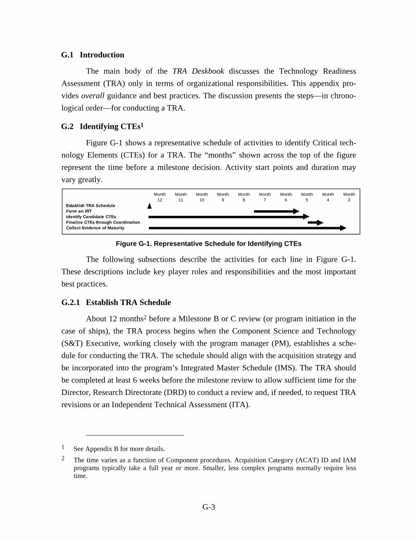
G-3
G.1 Introduction
The main body of the TRA Deskbook discusses the Technology Readiness
Assessment (TRA) only in terms of organizational responsibilities. This appendix pro-
vides overall guidance and best practices. The discussion presents the steps—in chrono-
logical order—for conducting a TRA.
G.2 Identifying CTEs1
Figure G-1 shows a representative schedule of activities to identify Critical tech-
nology Elements (CTEs) for a TRA. The “months” shown across the top of the figure
represent the time before a milestone decision. Activity start points and duration may
vary greatly.
Figure G-1. Representative Schedule for Identifying CTEs
The following subsections describe the activities for each line in Figure G-1.
These descriptions include key player roles and responsibilities and the most important
best practices.
G.2.1 Establish TRA Schedule
About 12 months2 before a Milestone B or C review (or program initiation in the
case of ships), the TRA process begins when the Component Science and Technology
(S&T) Executive, working closely with the program manager (PM), establishes a sche-
dule for conducting the TRA. The schedule should align with the acquisition strategy and
be incorporated into the program’s Integrated Master Schedule (IMS). The TRA should
be completed at least 6 weeks before the milestone review to allow sufficient time for the
Director, Research Directorate (DRD) to conduct a review and, if needed, to request TRA
revisions or an Independent Technical Assessment (ITA).
1 See Appendix B for more details. 2 The time varies as a function of Component procedures. Acquisition Category (ACAT) ID and IAM
programs typically take a full year or more. Smaller, less complex programs normally require less time.
Month Month Month Month Month Month Month Month Month Month12 11 10 9 8 7 6 5 4 3
Establish TRA ScheduleForm an IRTIdentify Candidate CTEsFinalize CTEs through CoordinationCollect Evidence of Maturity

G-4
Best Practice Include key TRA events in the IMP and IMS.
Best Practice Coordinate the TRA sche-dule with the DRD.
Key Player Roles and Responsibilities in Establishing the TRA Schedule
Component S&T Executive.3 Develop the TRA schedule jointly with the program office. The schedule should be coordinated with the DRD for ACAT ID and ACAT IAM acquisitions. As part of the coordination process, provide DRD a tech-nical overview of the program. This overview not only allows the Office of the Secretary of Defense (OSD) adequate time to prepare, but also provides an opportunity for OSD to share information on high-interest items. Provide training and support to the program office concerning its roles and responsi-bilities in the TRA process.
DRD. Approve the program’s proposed TRA schedule and provide timely comments along with any other conditions for agreement.
Agency head. When a program is not managed by one of the Components, the head of the lead agency should designate a person (e.g., the Chief Infor-mation Officer (CIO)) to carry out the Component S&T Executive’s TRA roles and responsibilities if that position does not exist in the agency. The person selected should be competent in the technical area of the program, independent of the program, and knowledgeable about the Department of Defense (DoD) acquisition process.
PM. Inform the Component S&T Executive of the need to conduct a TRA. Fund the TRA process. Support the Component S&T Executive in developing and coordinating the schedule. Designate a responsible individual in the program office to organize all TRA activities. That individual should be the interface point between the Component S&T Executive and the DRD. Key events in the TRA schedule should be included in the program’s Integrated Master Plan (IMP) and IMS.
G.2.2 Form an Independent Review Team (IRT)
Once a TRA schedule has been established, an IRT of subject matter experts
(SMEs) should be formed. The IRT will play a key role in identifying the CTEs and
assessing their maturity. The higher a program’s profile, the more scrutiny the TRA will
receive. The practices for determining the independence and expertise of the IRT should
be scrupulously followed. The use of an IRT makes the TRA process repeatable in the
3 The Component Science and Technology (S&T) Executive may delegate his/her roles and respon-sibilities to a TRA coordinator elsewhere in the organization.

G-5
Best Practice Establish an IRT of SMEs to identify candidate CTEs and assess their maturity.
sense that an entirely different set of SMEs on the IRT should identify the same CTEs
and assess them at the same level of maturity.
Key Player Roles and Responsibilities in Forming the IRT
Component S&T Executive. In conjunc-tion with the program office, establish an IRT of SMEs to identify candidate CTEs for the program and, eventually, to assess CTE maturity. The IRT should not provide advice or recommendations about programmatic courses of action as part of the TRA.
Subject matter expertise and independence from the program are the two principal qualifications for IRT membership. Members should be experts who have the demonstrated, current experience in the relevant fields. Exper-tise should extend beyond an individual technology to include sufficient domain knowledge within the IRT. The DRD office should be contacted if someone with the appropriate expertise cannot be found. That office can identify points of contact (POCs) in other Components who may be able to identify a person who has the needed skill set. Members should also be suffi-ciently independent of the developers (government or industry) as to not be unduly influenced by their opinions or have any actual or perceived biases. To avoid being influenced by the PM, an IRT member should not be directly working for or matrixed to the program or be a part of any Integrated Product Team (IPT) associated with the program.
For a joint program, each partner Service/agency should have representation on the IRT. Overall IRT membership should be balanced among Component, other government agencies (e.g., the National Aeronautics and Space Admin-istration (NASA), the National Institute of Standards and Technology (NIST), or the Department of Energy (DOE)), and non-government represen-tatives (e.g., academia, Federally Funded Research and Development Centers (FFRDCs), or science boards)). Where appropriate, an IRT member should have the authority to represent the views of his/her organization. Security clearances may also be needed.
IRT size will vary as a function of the program’s complexity. The IRT should include several people who have sufficient expertise to assess the maturity of any CTE. In no instance should the assessment rely on a single individual.4
4 Since CTEs cannot be finalized before the IRT is formed, beginning with a larger IRT for the CTE identification phase may be useful. After CTEs are finalized, the size of the IRT can be reduced if
G-6
Best Practice Keep the Component S&T Executive and the DRD informed.
An IRT chairperson5 should be designated based on a combination of leader-ship skills and technical capabilities.
Provide DRD the credentials of all prospective IRT members and sufficient information to confirm their independence from the program. Independence is sometimes difficult to establish. Factors to consider include the extent to which a person’s income is (has been) dependent on the program, the extent to which a person’s job appraisal is influenced by the program, the extent to which a person’s organization has influenced the program, the extent to which the person has a vested interest in technical choices to be made by the program, and any other institutional relationships or affiliation with the pro-gram. Extending these factors to include independence from the Program Executive Officer’s organization may be appropriate in some cases.
Train IRT members on their role in the TRA process. Include an overview of the system, an overview of the TRA process, criteria for identifying CTEs, and examples and instructions for applying the Technology Readiness Levels (TRLs). (IRT members might also be required to sign non-disclosure agree-ments and declare that they have no conflicts of interest.)
DRD. Concur with the composition of the IRT of SMEs or indicate condi-tions for agreement for ACAT ID and ACAT IAM programs.
IRT. Once formed, the IRT should inform the Component S&T Executive and the DRD on progress throughout the entire TRA process.
PM. Suggest to the Component S&T Executive the expertise and domain knowledge that the IRT will need.
G.2.3 Identify Candidate CTEs
The working definition of a CTE has been expanded by adding the phrase “or in
an area that poses major technological risk during detailed design or demonstration”:
A technology element is “critical” if the system being acquired depends on this technology element to meet operational requirements (within acceptable cost and schedule limits) and if the technology element or its application is either new or novel or in an area that poses major techno-logical risk during detailed design or demonstration.
certain expertise is not needed for the assessment phase. Non-voting SMEs can also be called as necessary.
5 As used in this Deskbook, the term “IRT chairperson” means the lead team member. The term’s use does not imply anything about the role of the Component S&T Executive.

G-7
Some confusion has arisen in determining whether a CTE is a “technology” or
solely a matter of “engineering.” This new phrase is more encompassing. If the technol-
ogy represents a major risk, it should be identified as a CTE so that the TRA will include
sufficient technical information that can be used to mitigate the risk.
CTE identification is fundamental to the TRA concept. To be useful, a readiness
assessment must include all CTEs. These CTEs should be identified in the context of the
program’s systems engineering process, based on a comprehensive review of the most
current system design and the program’s established technical work breakdown structure
(WBS) as distinguished from a programmatic or contractual WBS. For Information
Technology (IT)/Major Automated Information System (MAIS) acquisitions, the system
architecture and the software architecture should be used.
CTE identification should start well before the formal TRA process. In fact,
potential CTE identification begins during the Materiel Solution Analysis (MSA) phase,
which precedes Milestone A. An early evaluation of technology maturity, conducted
shortly after Milestone A, will further refine the potential CTEs. The Technology Devel-
opment Strategy (TDS) should reflect the result of a sufficiently thorough and disciplined
process designed to identify those technologies (including potential CTEs) that have a
realistic potential to be exploited beneficially in the Technology Development phase. As
system development proceeds, the possibility exists—through necessity or opportunity—
for the exploitation of technologies not previously considered. These technologies must
be given careful consideration to decide whether they are critical and sufficiently mature
to be included in the detailed design.
Finalizing the list of candidate CTEs for the TRA may require some time because
identification takes place in three stages:
1. Preparing an initial list of possible CTEs. The PM should prepare an initial list of possible CTEs using the most current system design (e.g., technical WBS) or system and software architectures as the starting point.
2. Conducting a review to determine the final list of CTE candidates. An IRT of SMEs should be used to determine which of the technologies included in the original list meet the criticality criteria in the CTE definition. CTE candidates are not constrained to those technologies on the PM’s initial list.
3. Securing final (i.e., DRD) approval of the list. DRD should indicate con-currence or non-concurrence with the final list of CTEs and seek additional information if necessary.
G-8
Best Practices Using the most current system
design, apply the CTE definition across the system technical WBS or system architecture and software architecture to identify an initial list of possible CTEs.
CTE identification must consider all the following environments:
Physical environment. For instance, mechanical components; processors, servers, and electronics; kinetic and kinematic; thermal and heat transfer; electrical and electromagnetic; threat; climatic—weather, temperature, partic-ulate; network infrastructure
Logical environment. For instance, software interfaces; security interfaces; Web-enablement; operating systems; service-oriented architecture(s); com-munication protocols; layers of abstraction; virtualization; coalition, federa-tion, and backward compatibility
Data environment. For instance, data formats, structures, models, schemas, and databases; anticipated data rates’ latency, jitter, transit loss, synchroniza-tion and throughput; data packaging and framing
Security environment. For instance, connection to firewalls; security proto-cols and appliqués; nature of the cyber adversary, methods of attack, trust establishment; security domains
User and use environment. For instance, scalability; upgradability; user training and behavior adjustments; user interfaces; organizational change/ realignments with system impacts; implementation plan.
CTEs can also include high-leverage and/or high-impact manufacturing technologies and life-cycle related technologies.
Key Player Roles and Responsibilities in the Identifying Candidate CTE Process
Component S&T Executive. Appoint an Action Officer (AO) to participate in the identification process—to the extent that his/her participation is con-sidered useful and valuable. The AO can provide beneficial TRA process and policy experience and information and can also minimize the chance that an unexpected problem will delay the process. The AO should understand the reasons for the inclusion and exclusion of technologies from the initial can-didate list before the list is shown to the DRD.
PM. Use the CTE definition to pre-pare an initial list of possible CTEs. This list should be prepared within the context of the program’s systems engineering approach and a compre-hensive review of the program’s most current design (or the govern-ment’s reference architecture) and established technical WBS or system architecture and software architecture.

G-9
Best Practice Be thorough and complete when assembling evidence of maturity. Include only neces-sary information.
Best Practices When the CTEs are uncertain,
discuss options with the DRD as early as possible.
When competing designs exist, identify possible CTEs separately for each design. If some overriding circumstance prohibits adequate technical planning before Milestone B,6 use the best available technical data and discuss the options with the DRD. Make key technical people avail-able to the IRT to clarify information about the program.
At Milestone C, begin with the CTEs identified at Milestone B. Much more will be understood about the relevant and operational environments. How-ever, unplanned performance could have been incorporated in the design during Engineering and Manufacturing Development (EMD). Therefore, conduct a careful review at Milestone C for any new CTEs.
If a program integrates critical systems or subsystems being developed in other programs, the PM of the higher order program (in preparation for a TRA) should identify the CTEs, including interface technologies, used on his/her side of the interfaces. This PM should request—through the appropriate Program Executive Office (PEO) or Component Acquisition Executive (CAE), as necessary—and obtain the identification of any CTEs in the lower order programs. The CTEs of the higher order system and all lower order systems or subsystems should be included in the initial list of possible CTEs that the PM of the higher order system develops.
IRT. Develop a list of candidate CTEs in conjunction with the program office. Inputs to this process include the initial list of possible CTEs devel-oped by the program office and specific technical planning performed by existing or previous contractors or government agencies. The IRT should be given full access to these data. On the basis of the CTE definition, the PM’s answers to questions, and the personal experience of IRT members, make final recommendations (with associated rationale) on the candidate CTEs that
6 One circumstance in which possible CTEs may not be firmly understood is the program initiation (Milestone A) TRA for ships. In such a case, consider information from Broad Agency Announce-ments (BAAs), Requests for Information (RFIs), and literature searches along with actual results from program-funded efforts in government laboratories or industry. If decisions on technology develop-ment agreements and contracts have been made, also use them as the basis for a TRA. Otherwise, identify any potentially critical technology included in any of the technology development proposals/ contracts.

G-10
Best Practice When coordinating the list of CTE candidates, include a brief description of the rationale for declaring a CTE to be critical.
should be assessed in the TRA. Technologies not included on the program’s initial list may be candidates.
G.2.4 Finalize CTEs Through Coordination
At this point, any disagreements in identifying CTEs should be resolved within
the Component. DRD concurrence on the CTEs should also be obtained.
Key Player Roles and Responsibilities in Finalizing CTEs Through Coordination
Component S&T Executive. Provide the list of candidate CTEs to the DRD for approval for ACAT ID and ACAT IAM programs. As part of this submission, explain the function of each CTE at the component, subsystem, and system levels and describe the rationale and criteria for declaring this technology critical. Also, briefly explain the process and crite-ria used to eliminate the CTE candidates that were not judged to be critical. Provide any additional information requested by the DRD.
DRD. Review the candidate list and provide any comments and recom-mended changes. Additions to the list can include any special-interest tech-nologies that warrant the rigor of the formal TRA process (e.g., radiation-hardened electronics or ground equipment survivability).
G.2.5 Collect Evidence of Maturity
Relevant data and information are needed to assess the TRL for each CTE. The
process of collecting and organizing the material for each CTE should begin as early as
possible. Figure G-1 shows this process as being concurrent with CTE identification.
Data collection should be complete shortly after the CTEs have been finalized. The
assessment process will be disrupted and delayed if relevant data are not readily accessi-
ble when these data are needed.
Key Player Roles and Responsibilities in Collecting Evidence of Maturity
PM. Compile component or subsystem test descriptions, environments, and results in the context of the system’s functional needs. Any other analyses and information necessary to assess and rationalize the maturity of the CTEs should also be included.

G-11
G.3 Assessing CTE Readiness7/Submitting the TRA Report8
Figure G-2 shows a representative schedule of activities for assessing CTE readi-
ness and submitting the TRA report, as a continuation of the schedule shown in Fig-
ure G-1.
Figure G-2. Representative Schedule for Assessing CTE Readiness
The following subsections describe the activities for each line in Figure G-2.
These descriptions include key player roles and responsibilities and the most important
best practices.
G.3.1 Assess CTE Maturity
Depending on the complexity of the system and the number of CTEs to be
assessed, completing the process may require several months. If all the data are available
immediately, assessing the maturity of a technology should not take very long. However,
the amount of time needed to complete the process is also a function of iterative data-
collection efforts, obtaining answers to questions, scheduling meetings, and so forth. To
maintain continuity and avoid incurring the unnecessary expense of familiarizing other
people with the TRA process and with the program being evaluated, the IRT that identi-
fied the candidate CTEs should also assess the maturity of these CTEs to the extent
practical.
Key Player Roles and Responsibilities in Assessing CTE Maturity
PM. Make key data, test results, and technical people available to the IRT to clarify information about the program.
IRT. Assess the TRL for all CTEs. Several recommended practices apply:
– Before the assessment process begins, ensure a sufficient understanding of the requirements, identified capabilities, system and software archi-tectures, concept of operation (CONOPS), and/or the concept of employ-ment to define the relevant and operational environments. Also ensure
7 See Appendix C for more details. 8 See Appendix A for more details.
G-12
Best Practice Use the IRT to assess CTE matu-rity. Base all conclusions on objec-tive evidence and the technical expertise of the IRT.
that the understanding of design details is sufficient enough to evaluate how the CTE will function and interface. Without such understanding, a CTE cannot be assessed as mature.
– If the IRT is large enough, form subteams based on mem-bers’ areas of expertise. Have these subteams deliberate and then recommend the appropri-ate TRL and defend their positions to the entire IRT. The IRT chairperson should attempt to achieve consensus on the final score and supporting rationale for a tech-nology, but consensus is not mandated. In some cases, the IRT chair-person may have to make the decision on the final score, taking into account the unique expertise provided by each IRT member weighed against the technology under consideration. Strong dissenting positions should be documented.
– Do not constrain the assessment process to a validation of a “program-developed” position on the TRL.9
Component S&T Executive. Conduct the TRA in accordance with Compo-nent guidelines and procedures. Keep the DRD informed.
The Component should use TRLs to communicate TRA findings. Refer to Appen-
dix C, Table C-1 (hardware) and C-2 (software), for TRL definitions, descriptions, and
supporting information.10 Table C-3 provides additional TRL definitions.
G.3.2 Prepare, Coordinate, and Submit the TRA Report
Allow at least 2 weeks for the Component coordination process before TRA sub-
mission. The TRA should be submitted to the DRD according to the agreed-upon sche-
dule—normally, at least 6 weeks before a scheduled Milestone B or Milestone C. See
Figure G-2.
9 When evaluating evidence of maturity, consider whether the testing was comprehensive for the sample sizes and for the environments measured and whether sufficient understanding exists to extend the test results analytically to other environments.
10 Appendix E contains a discussion of biomedical TRLs. Appendix H is an easy-reference display of the hardware/software TRLs and additional definitions of TRL descriptive terms.

G-13
Best Practice The TRA report should consist of (1) short description of the program; (2) the IRT credentials; (3) IRT delib-erations, findings, conclusions, sup-porting evidence, and major dissenting opinions; (4) other technical information deemed pertinent by the Component S&T Executive; and (5) a cover letter signed by the Component S&T Executive.
Key Player Roles and Responsibilities in Preparing, Coordinating, and Submitting the
TRA Report
PM. Draft a short description of the program for the TRA report.
IRT. Summarize the IRT’s credentials and draft an account of its findings (along with the supporting evidence that forms the basis for these findings).11 All IRT delibera-tions, findings, and conclu-sions should be included. Present the evidence and rationale for the final assessment clearly and logically. Evidence could include records of tests or applications of the technology, technical papers, reports, presentations, and so forth. Explain how the material was used or interpreted to make the assessment. Reference the sources and the pages in these sources for the evi-dence presented in the report for determining the TRL. Vague references to test results or test documents are not sufficient. The material should explain the function of each CTE at the component, subsystem, and system levels. The TRA report should also contain an explicit description of the program increments or spirals covered.
The TRA report at Milestone C should highlight the assessment of any addi-tional CTEs identified during EMD. Also, describe the results of develop-mental test and evaluation (DT&E) for all CTEs.
Component S&T Executive. For ACAT ID and ACAT IAM programs, review the TRA report and indicate agreements or disagreements with the IRT findings in the TRA report cover letter and provide any other pertinent technical material that supports or does not support the position of the IRT. A PM’s assessment of TRLs can also be included in the cover letter. Material provided by the S&T Executive should be clearly differentiated from the material provided by the IRT. Sign the cover letter and forward the TRA report to the CAE or agency head. At the same time, send an information copy to the DRD.
CAE or Agency head. For ACAT ID and ACAT IAM programs, route the TRA report to the DRD, with an assessed TRL for each CTE.
11 This material is typically prepared by and, at a minimum, approved by the IRT chairperson.

G-14
If no CTEs were identified using the criteria described in Section G.2, the report
should consist of a brief description of the program; the IRT credentials, rationale, and
criteria for determining that no candidate technology is critical; and a cover letter signed
by the Component S&T Executive.
Appendix A contains a template for the TRA report.
G.3.3 DRD Review and Evaluation
The DRD evaluates the Component TRA in cooperation with the Component
S&T Executive and the PM. An AO, designated by the DRD, will normally lead the
evaluation effort. After an initial evaluation, the AO can either concur with the evaluation
or request revisions. In the latter case, the TRA will be updated and returned to the AO
for further review.
G.3.3.1 Performing an Independent TRA
If the DRD does not concur with the findings of the Component TRA, an ITA can
be conducted. This independent assessment should be a positive contribution to the
acquisition program. For example, it could result in a revised, more realistic schedule, the
use of an alternative technology, or a revised, evolutionary acquisition strategy. The ITA
should be conducted as quickly as possible—whether this requires one day or several
months. In practice, a decision to perform an ITA is rarely made.
G.3.3.2 Preparing the Evaluation Memo
The AO prepares a memorandum for the DRD signature. This memorandum
contains the evaluation results of the Component TRA and of the ITA (if an ITA was
conducted). It indicates either concurrence or concurrence with reservations concerning
the findings of the Component TRA, or it contains the findings of the ITA. If the AO
deems any CTE to be insufficiently mature for the upcoming milestone, he/she informs
the Component S&T Executive and the PM so that all involved have an opportunity to
reach agreement on appropriate action.
The memorandum is sent to the Overarching Integrated Product Team (OIPT) and
the Defense Acquisition Board (DAB) or to the Information Technology Overarching
Integrated Product Team (IT OIPT) and the Information Technology Acquisition Board
(ITAB).

G-15
The evaluation memorandum should be signed at least 15 days before a Mile-
stone B or Milestone C review meeting.12 This memo is forwarded to the Milestone Deci-
sion Authority (MDA) and, if there is non-concurrence, to the OIPT/IT OIPT and the
DAB/ITAB.
12 If this 15-day window is not possible, the date of the review meeting should be rescheduled so the OIPT and DAB members or the IT OIPT and ITAB members have ample time to review all the rele-vant information. As appropriate, the memorandum should address recommendations to the MDA for issues that should be raised at the milestone review and for items to be included in the Acquisition Decision Memorandum (ADM).

H-1
Appendix H.
Easy-Reference Display of the
Hardware/Software TRLs and Additional TRL Definitions

Hardware and Software Technology Readiness Levels (TRLs)
Hardware TRL Definitions, Descriptions, and Supporting Information Software TRL Definitions, Descriptions, and Supporting Information
TRL Definition Description Supporting Information TRL Definition Description Supporting Information
1 Basic principles observed and reported.
Lowest level of technology readiness. Scientific research begins to be translated into applied research and development (R&D). Exam-ples might include paper studies of a technology’s basic properties.
Published research that identifies the principles that underlie this technology. References to who, where, when.
1 Basic principles observed and reported.
Lowest level of software technology readiness. A new software domain is being investigated by the basic research community. This level extends to the development of basic use, basic properties of software architecture, mathematical formulations, and general algorithms.
Basic research activities, research articles, peer-reviewed white papers, point papers, early lab model of basic concept may be useful for substantiating the TRL.
2 Technology concept and/or application formulated.
Invention begins. Once basic principles are observed, practical applications can be invented. Applications are speculative, and there may be no proof or detailed analysis to support the assump-tions. Examples are limited to analytic studies.
Publications or other references that outline the application being considered and that provide analysis to support the concept.
2 Technology concept and/or application formulated.
Once basic principles are observed, practical applications can be invented. Applications are speculative, and there may be no proof or detailed analysis to support the assumptions. Examples are limited to analytic studies using synthetic data.
Applied research activities, analytic studies, small code units, and papers comparing competing technologies.
3 Analytical and experimental critical function and/or charac-teristic proof of concept.
Active R&D is initiated. This includes analytical studies and labora-tory studies to physically validate the analytical predictions of sepa-rate elements of the technology. Examples include components that are not yet integrated or representative.
Results of laboratory tests performed to measure parameters of interest and comparison to analytical predictions for critical subsys-tems. References to who, where, and when these tests and com-parisons were performed.
3 Analytical and experimental critical function and/or charac-teristic proof of concept.
Active R&D is initiated. The level at which scientific feasibility is demonstrated through analytical and laboratory studies. This level extends to the development of limited functionality environments to validate critical properties and analytical predictions using non-inte-grated software components and partially representative data.
Algorithms run on a surrogate processor in a laboratory environ-ment, instrumented components operating in a laboratory environ-ment, laboratory results showing validation of critical properties.
4 Component and/or bread-board validation in a laboratory environment.
Basic technological components are integrated to establish that they will work together. This is relatively “low fidelity” compared with the eventual system. Examples include integration of “ad hoc” hardware in the laboratory.
System concepts that have been considered and results from testing laboratory-scale breadboard(s). References to who did this work and when. Provide an estimate of how breadboard hardware and test results differ from the expected system goals.
4 Module and/or subsystem vali-dation in a laboratory envi-ronment (i.e., software prototype devel-opment environment).
Basic software components are integrated to establish that they will work together. They are relatively primitive with regard to efficiency and robustness compared with the eventual system. Architecture development initiated to include interoperability, reliability, maintain-ability, extensibility, scalability, and security issues. Emulation with current/legacy elements as appropriate. Prototypes developed to demonstrate different aspects of eventual system.
Advanced technology development, stand-alone prototype solving a synthetic full-scale problem, or standalone prototype processing fully representative data sets.
5 Component and/ or breadboard validation in a relevant environment.
Fidelity of breadboard technology increases significantly. The basic technological components are integrated with reasonably realistic supporting elements so they can be tested in a simulated environ-ment. Examples include “high-fidelity” laboratory integration of components.
Results from testing a laboratory breadboard system are integrated with other supporting elements in a simulated operational environ-ment. How does the “relevant environment” differ from the expected operational environment? How do the test results compare with expectations? What problems, if any, were encountered? Was the breadboard system refined to more nearly match the expected sys-tem goals?
5 Module and/or subsystem vali-dation in a relevant environment.
Level at which software technology is ready to start integration with existing systems. The prototype implementations conform to target environment/interfaces. Experiments with realistic problems. Simu-lated interfaces to existing systems. System software architecture established. Algorithms run on a processor(s) with characteristics expected in the operational environment.
System architecture diagram around technology element with criti-cal performance requirements defined. Processor selection analy-sis, Simulation/Stimulation (Sim/Stim) Laboratory buildup plan. Software placed under configuration management. Commercial-of-the-shelf/government-off-the-shelf (COTS/GOTS) components in the system software architecture are identified.
6 System/subsys-tem model or prototype dem-onstration in a relevant environment.
Representative model or prototype system, which is well beyond that of TRL 5, is tested in a relevant environment. Represents a major step up in a technology’s demonstrated readiness. Examples include testing a prototype in a high-fidelity laboratory environment or in a simulated operational environment.
Results from laboratory testing of a prototype system that is near the desired configuration in terms of performance, weight, and vol-ume. How did the test environment differ from the operational envi-ronment? Who performed the tests? How did the test compare with expectations? What problems, if any, were encountered? What are/were the plans, options, or actions to resolve problems before moving to the next level?
6 Module and/or subsystem vali-dation in a relevant end-to-end environment.
Level at which the engineering feasibility of a software technology is demonstrated. This level extends to laboratory prototype imple-mentations on full-scale realistic problems in which the software technology is partially integrated with existing hardware/software systems.
Results from laboratory testing of a prototype package that is near the desired configuration in terms of performance, including physi-cal, logical, data, and security interfaces. Comparisons between tested environment and operational environment analytically under-stood. Analysis and test measurements quantifying contribution to system-wide requirements such as throughput, scalability, and reli-ability. Analysis of human-computer (user environment) begun.
7 System proto-type demonstra-tion in an operational environment.
Prototype near or at planned operational system. Represents a major step up from TRL 6 by requiring demonstration of an actual system prototype in an operational environment (e.g., in an aircraft, in a vehicle, or in space).
Results from testing a prototype system in an operational environ-ment. Who performed the tests? How did the test compare with expectations? What problems, if any, were encountered? What are/were the plans, options, or actions to resolve problems before moving to the next level?
7 System proto-type demonstra-tion in an operational high-fidelity environment.
Level at which the program feasibility of a software technology is demonstrated. This level extends to operational environment proto-type implementations, where critical technical risk functionality is available for demonstration and a test in which the software tech-nology is well integrated with operational hardware/software sys-tems.
Critical technological properties are measured against requirements in an operational environment.
8 Actual system completed and qualified through test and demonstration.
Technology has been proven to work in its final form and under expected conditions. In almost all cases, this TRL represents the end of true system development. Examples include developmental test and evaluation (DT&E) of the system in its intended weapon system to determine if it meets design specifications.
Results of testing the system in its final configuration under the expected range of environmental conditions in which it will be expected to operate. Assessment of whether it will meet its opera-tional requirements. What problems, if any, were encountered? What are/were the plans, options, or actions to resolve problems before finalizing the design?
8 Actual system completed and mission qualified through test and demonstration in an operational environment.
Level at which a software technology is fully integrated with opera-tional hardware and software systems. Software development documentation is complete. All functionality tested in simulated and operational scenarios.
Published documentation and product technology refresh build schedule. Software resource reserve measured and tracked.
9 Actual system proven through successful mis-sion operations.
Actual application of the technology in its final form and under mis-sion conditions, such as those encountered in operational test and evaluation (OT&E). Examples include using the system under operational mission conditions.
OT&E reports. 9 Actual system proven through successful mission-proven operational capabilities.
Level at which a software technology is readily repeatable and reusable. The software based on the technology is fully integrated with operational hardware/software systems. All software docu-mentation verified. Successful operational experience. Sustaining software engineering support in place. Actual system.
Production configuration management reports. Technology inte-grated into a reuse “wizard.”

Additional TRL Definitions
Additional TRL Definitions
Term Definition
Breadboard Integrated components that provide a representation of a system/subsystem and that can be used to determine concept feasibility and to develop technical data. Typically configured for laboratory use to demonstrate the technical principles of immediate interest. May resemble final system/subsystem in function only.
High Fidelity Addresses form, fit, and function. A high-fidelity laboratory environment would involve testing with equipment that can simulate and validate all system specifications within a laboratory setting.
Low Fidelity A representative of the component or system that has limited ability to provide anything but first-order information about the end product. Low-fidelity assessments are used to provide trend analysis.
Model A functional form of a system, generally reduced in scale, near or at operational specification. Models will be sufficiently hardened to allow demonstration of the technical and operational capabilities required of the final system.
Operational Environment Environment that addresses all the operational requirements and specifications required of the final system to include platform/packaging.
Prototype A physical or virtual model used to evaluate the technical or manufacturing feasibility or military utility of a particular technology or process, concept, end item, or system.
Relevant Environment Testing environment that simulates both the most important and most stressing aspects of the operational environment.
Simulated Operational Environment Either (1) a real environment that can simulate all the operational requirements and specifications required of the final system or (2) a simulated environment that allows for testing of a virtual prototype. Used in either case to determine whether a developmental system meets the operational requirements and specifications of the final system.