technology and manufacturing readiness of early market ... · xii figures figure 1. technology...
TRANSCRIPT
PNNL-21473
Prepared for the U.S. Department of Energy under Contract DE-AC05-76RL01830
Technology and Manufacturing Readiness of Early Market Motive and Non-Motive Hydrogen Storage Technologies for Fuel Cell Applications Ewa C.E. Rönnebro June 2012


PNNL-21473
Technology and Manufacturing Readiness of Early Market Motive and Non-Motive Hydrogen Storage Technologies for Fuel Cell Applications
Ewa C.E. Rönnebro
June 2012
Prepared for
the U.S. Department of Energy
under Contract DE-AC05-76RL01830
Pacific Northwest National Laboratory
Richland, Washington 99352


iii
Executive Summary
Fuel cells (FCs) are considered a key future energy efficient power generation technology.
The Department of Energy’s (DOE’s) Fuel Cell Technologies Program (FCTP) is focused on key
challenges concerning fuel cells and hydrogen technologies including hydrogen production,
delivery, distribution and storage. Recently, the FCTP has broadened its focus from light-duty
vehicle application to include near-term market applications, and hydrogen storage is necessary
for these fuel cell applications. The focus of this report is hydrogen storage for near-term
commercial fuel cell applications. The report documents the methodology and results of an effort
to identify hydrogen storage technologies’ technical and manufacturing readiness for early
market motive and non-motive applications and to provide a path forward toward
commercialization. Motive applications include materials handling equipment (MHE) and
ground support equipment (GSE), such as forklifts, tow tractors, and specialty vehicles such as
golf carts, lawn mowers and wheel chairs. Non-motive applications are portable, stationary or
auxiliary power units (APUs) and include portable laptops, backup power, remote sensor power,
and auxiliary power for recreational vehicles, hotels, hospitals, etc.
Hydrogen storage technologies assessed include metal hydrides, chemical hydrogen storage,
sorbents and hydrogen storage cylinders including gaseous storage, cryo-compressed and liquid
storage. The assessments are based on a combination of Technology Readiness Level (TRL) and
Manufacturing Readiness Level (MRL) designations that enable evaluation of hydrogen storage
technologies at varying levels of development. The manufacturing status could be established
from eight risk elements: Technical Maturity, Design, Materials, Cost & Funding, Process
Capability, Personnel, Facilities and Manufacturing Planning. This approach provides a logical
methodology and roadmap to enable the identification of hydrogen storage technologies, their
advantages/disadvantages, gaps and research and development (R&D) needs on an unbiased and
transparent scale that is easily communicated to interagency partners. This technology readiness
assessment (TRA) report documents the process used to conduct the technology and
manufacturing readiness assessment (TRA/MRA), reports the TRL and MRL for each assessed
technology and provides recommendations based on the findings.
To determine the state of the art and status of technology maturation gaps, Pacific Northwest
National Laboratory (PNNL) prepared a questionnaire to assign TRL and MRL for each
hydrogen storage technology. The questionnaire was sent to hydrogen storage technology
developers and manufacturers who were asked to perform a self-assessment. We included both
domestic and international organizations including U.S. national laboratories, U.S. companies,
European companies and Japanese companies. A copy of the questionnaire is found in Appendix
A2. PNNL collected the data and performed an analysis to deduce the level of maturity and to
provide program recommendations.
iv
It was found that the highest TRLs for existing technologies are for metal hydrides with TRL
7−9 and hydrogen storage cylinders with TRL 8−9; and are likely candidates for early market
applications. For metal hydrides, the highest Risk Elements for Manufacturing Readiness were
identified to be Process Capability, Facilities and Manufacturing Planning. Regarding tanks for
compressed hydrogen gas storage, for metal-lined composite tanks, the highest Risk Elements
were identified to be Personnel and Manufacturing Planning. Metal tanks and metal-lined
composite tanks have been demonstrated in relevant environments and low rate initial production
(LRIP) is in progress, ready for full rate production (FRP) if demand increases. Funded efforts to
decrease cost are already in progress. Metal hydrides for stationary storage for APUs could also
have an impact on early markets, but systems integration efforts would be necessary as a first
stage. Chemical hydrogen storage materials have fairly low TRL levels of below 5. They are
being used to a limited extent, mainly in one-use cartridges for portable power, but, as a
materials class, chemical hydrogen storage materials are still in need of technology development
and system validation and appear to be more suitable for mid-term or long-term markets. Sorbent
materials have not advanced beyond TRL 2, except for one material at TRL 5 that is not yet
ready for transition to LRIP. System validation is necessary before demonstrating an integrated
system to proceed toward LRIP, and sorbents appear to be more suitable for mid-term to long-
term markets.
Conclusions and Recommendations include:
Metal hydrides are identified to have the greatest impact on the early markets for MHE
and GSE, provided that funds are provided for systems integration and demonstration in
relevant environments.
To reach early commercialization of advanced metal hydride-based technologies, focus
needs to be on Process Capability, Facilities and Manufacturing Planning to reach
LRIP.
Chemical hydrogen storage materials can be used in one-use cartridges for disposal or
recycling, but demand is currently low. To penetrate an early market for portable power
and consumer electronics, technology development and demonstration programs are
needed to transition the technology.
Many chemical hydrogen storage materials and complex metal hydrides show promise
for commercialization, but may realistically be for mid-term to long-term markets as
evident from their low TRL/MRLs (below 5).
Sorbent materials are more suitable for mid-term to long-term markets. To advance
toward LRIP, a technology development program to demonstrate an integrated system
is needed.
v
Hydrogen storage cylinders are advanced with high TRL/MRLs and have been
demonstrated in MHE fleets, but, there is a need for further development of low-cost
tank materials.
Gaseous hydrogen storage tanks are already commercially available, but demand is low,
not reaching quantities for LRIP (~1000 units/year). Therefore, a market transformation
program would help increase demand for FCs and hydrogen storage.
Cryo-compressed/ liquid hydrogen storage has been demonstrated on-board storage of
vehicles, however, the level of readiness for LRIP is low.
It is important to routinely perform TRA/MRA analysis of hydrogen storage
technologies in parallel with the ongoing TRA/MRA analysis of FCs, to monitor
progress and to identify gaps and R&D needs. It is recommended that an ongoing
TRA/MRA activity on hydrogen storage technologies is established and that
participation in this activity is a requirement for all co-funded demonstration activities.


vii
Acknowledgments
PNNL’s activities are supported by the DOE Fuel Cell Technologies Program under DOE
contract DE-AC05-76RL01830 and we especially thank Ned Stetson, Carol Read, Grace Ordaz,
and Scott McWhorter in the Fuel Cell Technology Office for valuable comments and
discussions. We sincerely thank all the hydrogen storage companies and researchers that
participated in the information gathering.


ix
Acronyms and Abbreviations
DoD U.S. Department of Defense
DOE U.S. Department of Energy
FC fuel cell
FCTP U.S. Department of Energy Fuel Cell Technologies Program
FRP full rate production
LLC Limited Liability Company
LRIP low rate initial production
MHE material handling equipment
MRA Manufacturing Readiness Assessment
MRL Manufacturing Readiness Level
NREL National Renewable Energy Laboratory
PEM polymer electrolyte membrane
PNNL Pacific Northwest National Laboratory
R&D research and development
SNL Sandia National Laboratories
TRA Technology Readiness Assessment
TRL Technology Readiness Level

xi
Contents
Executive Summary .......................................................................................................................... iii
Acknowledgments .............................................................................................................................vii
Acronyms and Abbreviations ............................................................................................................ ix
1.0 Introduction ............................................................................................................................. 1.1
1.1 Objective ......................................................................................................................... 1.2
1.2 Scope of This Study ........................................................................................................ 1.2
1.3 Hydrogen Storage Technologies ..................................................................................... 1.3
1.3.1 Metal Hydrides ..................................................................................................... 1.3
1.3.2 Chemical Hydrogen Storage Materials ................................................................ 1.4
1.3.3 Sorbents ................................................................................................................ 1.5
1.3.4 Hydrogen Storage Cylinders ................................................................................ 1.5
2.0 Method ..................................................................................................................................... 2.1
2.1 Project Approach ............................................................................................................. 2.1
2.2 Technology Readiness Levels ......................................................................................... 2.2
2.3 Manufacturing Readiness Levels .................................................................................... 2.2
2.4 Risk Elements .................................................................................................................. 2.3
2.5 Technology Readiness Assessment Methodology .......................................................... 2.4
2.6 TRA Questionnaires and Validation ............................................................................... 2.5
3.0 Results ..................................................................................................................................... 3.1
3.1 Metal Hydrides TRA Analysis ........................................................................................ 3.2
3.2 Chemical Hydrogen Storage Materials TRA Analysis ................................................... 3.5
3.3 Sorbents TRA Analysis ................................................................................................... 3.6
3.4 Hydrogen Storage Cylinders TRA Analysis ................................................................... 3.6
4.0 Summary and Conclusions from Technology and Manufacturing Readiness Assessment ..... 4.1
5.0 Recommendations ................................................................................................................... 5.1
6.0 References ............................................................................................................................... 6.1
Appendix Activities of Hydrogen Storage Technology Companies and Assessment Questions .... 6.3
xii
Figures
Figure 1. Technology Development Model ..................................................................................... 2.4
Tables
Table 1. Technology and Manufacturing Readiness Levels ............................................................ 2.4
Table 2. Hydrogen Storage Technology Developers and Manufacturers in the U.S., Europe and
Japan ........................................................................................................................................ 3.1
Table 3. MRLs for Metal Hydride-Based Technologies .................................................................. 3.3
Table 4. MRLs for Chemical Hydrogen Storage-Based Technologies ............................................ 3.5
Table 5. MRLs for Sorbent-Based Technologies ............................................................................. 3.6
Table 6. MRLs for Hydrogen Storage Cylinders ............................................................................. 3.8

1.1
1.0 Introduction
Fuel cells (FCs) are considered a key future energy storage technology. The United States,
Japan, Germany and South Korea are the leading countries in developing these technologies with
established research and development (R&D) and market transformation programs and
government-assisted projects to support emerging markets. During the past two to five years,
tremendous progress has been made; stack and system costs have been lowered by a factor of
two, and durability and efficiency are much improved. However, FCs are still not cost
competitive with established technologies based on gas, oil or batteries and governmental
support is therefore necessary.
The Department of Energy’s (DOE’s) Fuel Cell Technologies Program (FCTP) funds the
development and advancement of fuel cell and hydrogen technologies for automotive powertrain
systems. In the Program Plan from September 2011 (DOE 2011a), portable power and stationary
storage applications are included. The FCTP is addressing the key challenges for fuel cells and
the hydrogen infrastructure, including hydrogen production, delivery and storage. The focus of
this report is hydrogen storage.
Several reports have investigated the status of FCs with respect to technology development
needs and market readiness. It is only during the past five years that hydrogen storage technology
development has made remarkable progress, resulting in advancement toward
commercialization. This report documents the methodology and results of an effort to identify
hydrogen storage technologies’ technical and manufacturing readiness.
There are FCs widely commercially available based on polymer electrolyte membranes
(PEMs), direct methanol fuel cells (DMFC), solid oxide fuel cells (SOFC), phosphoric acid fuel
cells (PAFC) and molten carbonate fuel cells (MCFC). In a report prepared for DOE by Battelle
(Mahadevan et al., 2007), applications for 1−250 kW PEM FCs were identified as feasible
technologies for near-term application in the distributed electric power generation market. The
report was focused on market segments (airports, hospitals, grocery stores, data centers, ski
resorts, etc.) and cost analysis and driven by user requirements. Mahadevan et al. identified
requirements for successful market penetration and three near-term market opportunities for
PEM FCs, including state and local emergency response agencies, forklifts in high-throughput
distribution centers, and airport ground support equipment. “The pathway to fuel cell vehicles
will likely include the introduction of direct hydrogen PEM FCs in near-term markets with fewer
technical challenges than the automobile market” (Mahadevan et al., 2007).
In a report by Oak Ridge National Laboratory (Greene et al., 2011), the current status of non-
automotive fuel cell markets was investigated. They found that the PEM fuel cell manufacturers
are attempting to establish themselves in backup and telecommunications, materials handling
equipment (MHE) such as forklifts and micro combined heat and power (CHP). About 50% cost
reduction was achieved over the past two to five years. Government incentives are essential to
sustain the U.S. FC industry. Most manufacturers believe the production volumes must increase

1.2
by a factor of three to be competitive and they are capable of increasing their production capacity
by 50−300% within one year.
In a recent report on “Pathways to Commercial Success” (DOE 2011b), Pacific Northwest
National Laboratory (PNNL) performed a patent analysis and identified 313 patents associated
with research at national laboratories, private companies and universities supported by fuel cell
technology since 1977, including 167 fuel cell patents, 108 production/delivery patents and 38
storage patents. More than 150 of them were issued after 2004. The storage area, which is the
focus of this report, had 68% of the awards to national laboratories. However, the storage patents
are only 12% of all patents, and even fewer, 6.6%, made it to commercial products according to
this report. This demonstrates that the hydrogen storage technologies need to further advance to
catch up with technology needs; this study will help identify the needs to reach
commercialization.
1.1 Objective
PNNL’s objective in this report is to provide DOE with a technology and manufacturing
readiness assessment (TRA/MRA) to identify hydrogen storage technologies’ maturity levels for
early market motive and non-motive applications and to provide a path forward toward
commercialization.
The Technology Readiness Assessment (TRA) is based on a combination of Technology
Readiness Level (TRL) and Manufacturing Readiness Level (MRL) designations that enable
evaluation of hydrogen storage technologies in varying levels of development. This approach
provides a logical methodology and roadmap to enable the identification of hydrogen storage
technologies, their advantages/disadvantages, gaps and R&D needs on an unbiased and
transparent scale that is easily communicated to interagency partners.
The TRA report documents the process used to conduct the TRA, reports the TRL and MRL
for each assessed technology and provides recommendations based on the findings.
1.2 Scope of This Study
Over the past few years, the DOE FCTP’s hydrogen storage activities have focused on on-
board transportation applications. Recently, the FCTP broadened its focus to include near-term
markets, and hydrogen storage is necessary for these fuel cell applications. Our study establishes
early market readiness of each identified hydrogen technology and provides a path forward for
advancing the technologies to maturity.
Near-term markets for FC technologies can be divided into motive and non-motive
applications. Motive applications include MHE and airport ground support equipment (GSE),
such as forklifts, tow tractors, and, specialty vehicles such as golf carts, lawn mowers and wheel
chairs. Non-motive applications are portable, stationary or auxiliary power units (APUs) and

1.3
include portable laptops, backup power, remote sensor power, and auxiliary power for
recreational vehicles, hotels, hospitals, etc. Specific hydrogen-storage performance requirements
for each application had not been defined, but are a key to successful market penetration. Two
parallel studies by Sandia National Laboratories (SNL) (Klebanoff et al., 2012) and the National
Renewable Energy Laboratory (NREL) (Kurtz et al., 2012) provided for the first time hydrogen
storage technical needs for early market fuel cell applications with system performance
requirements. SNL identified five non-motive markets: construction, aviation ground support,
telecommunications, portable power and consumer electronics. NREL identified three motive
markets: MHE, public transit and autonomous vehicles. In PNNL’s study, we establish market
readiness levels for each hydrogen storage technology to provide a path forward toward
commercialization.
To determine the status of the state of the art technology and the maturation gaps, PNNL
prepared a questionnaire to assign TRL and MRL for each hydrogen storage technology. The
questionnaire was sent to hydrogen storage technology developers and manufacturers who were
asked to perform a self-assessment to be described in detail below. We included both domestic
and international organizations including U.S. national laboratories, U.S. companies, European
companies and Japanese companies. PNNL collected the data and performed an analysis to
deduce the level of maturity and provide program recommendations.
1.3 Hydrogen Storage Technologies
The DOE FCTP is developing technologies to enable the lightweight, inexpensive and dense
storage of hydrogen. For PEM fuel cell applications, the optimum operating pressure-
temperature window is in the range of 1−10 atm and 25−120°C. Hydrogen can be stored
chemically in a material, or as a gas or liquid in pressurized or cryo-compressed tanks. Today,
physical storage of hydrogen as a compressed gas or liquid (cryogenic) is used in on-board
storage for vehicles. In Japan, Toyota has a fuel cell car with a high-pressure tank with TiCr-
based metal hydride. However, the tanks are currently more expensive, heavier and bulkier than
conventional fuel tanks. Chemical storage of hydrogen in a material has the potential to reduce
cost and volume compared to conventional physical storage techniques. Further details on the
plans for research, development, and demonstration of hydrogen storage technologies are
provided in the Hydrogen and Fuel Cells Program Plan (DOE 2011a) and include early market
stationary and portable fuel cell applications.
This report concerns the state of the art of existing hydrogen storage technologies; below we
provide a short introduction to each storage technique: metal hydrides, chemical hydrogen
storage materials, sorbents and hydrogen storage cylinders.
1.3.1 Metal Hydrides
Metal hydrides are materials that store hydrogen reversibly by absorption and desorption of
hydrogen at certain pressures and temperatures. There are mainly two chemically distinguished

1.4
metal hydrides; 1) intermetallic compound hydrides and 2) complex metal hydrides. In the
intermetallic compound hydrides, hydrogen is stored interstitially in the metal matrix, which
basically remains the same upon absorption and desorption. Metal hydrides are typically
composed of metal alloys and the materials’ gravimetric capacity is in the range of 1−3 wt%
hydrogen, operating at or near the PEM fuel cell required pressure and temperature ranges, some
of them at room temperature. There are hundreds of characterized intermetallic compound metal
hydrides found in the literature, from rare-earth based alloys to lightweight titanium-based alloys
with the possibility to tune pressure and temperature for specific applications. There are already
a few companies in the U.S. and Europe that provide metal hydride containers for fuel-cell
powered MHE applications, such as forklifts.
Complex metal hydrides have the potential for higher hydrogen content up to about 20 wt%,
with hydrogen chemically bonded to a central metal atom in an anionic complex stabilized in a
matrix of one or more cations. The chemical bond is moderate to very strong, and hydrogen is
therefore released at higher temperatures. Moreover, the decomposition mechanism is more
complex and may result in multiple product materials phases which may only reabsorb hydrogen
to a small extent unless very high temperatures are used or specific manipulations are applied,
including scaffolding, dopants, particle size reduction and forming reactive hydride composites.
Kinetics for uptake and release are slow in comparison with the intermetallic compound metal
hydrides. For automotive applications kinetics need to be fast, but there are other applications,
such as stationary uses, that do not demand fast kinetics. Moreover, long cycle life has not been
demonstrated and thermal management during refueling needs to be resolved.
Complex metal hydrides include alanates, borohydrides and amides such as NaAlH4,
Mg(BH4)2 and Li2NH. Sodium alanate, NaAlH4, is the most investigated reversible complex
metal hydride. When it is catalyzed with titanium dopants, it operates at about 150°C with a
maximum materials-based capacity of 5.5 wt% and 4 wt% has been reversibly demonstrated. A
few developers in the U.S. and Germany have developed sodium alanate for automotive and
mobile applications. Reactive hydride composites include materials systems such as
LiBH4+MgH2, which is the most investigated composite, operating at 350°C. These mixtures
typically have improved thermodynamics relative to the components.
1.3.2 Chemical Hydrogen Storage Materials
Chemical hydrogen storage materials typically release large amounts of hydrogen at low
temperatures (< 200°C) through a chemical reaction, but cannot easily be rehydrided as
intermetallic compound metal hydrides can. Instead, regeneration schemes of the spent material
need to be developed; it is typically performed off-board in another location. It is also possible to
use a chemical hydrogen storage material canister one time and dispose of or recycle it when
empty, such as for portable power. Some of the most promising solid-state materials are
ammonia borane (19.6 wt%), lithium alanate (7.8 wt%) and alane (10 wt%). Another approach to
release hydrogen is through chemical reactions such as hydrolysis, for example reaction of water
with NaBH4 to form NaBO2 or with MgH2 to form Mg(OH)2. Recently, liquid media have been

1.5
proposed, including organic compounds and cyclic boron-nitrogen compounds, but these are in
an early stage of development (TRL 1−2).
1.3.3 Sorbents
Sorbents are high surface area materials such as metal organic frameworks and carbon-based
materials such as carbon nanotubes, nanofibers and aerogels. The hydrogen molecules are
reversibly adsorbed on the surface of these materials, typically with rapid kinetics; however,
cryogenic temperatures are often needed to increase the hydrogen content. Hydrogen spillover is
a potential technique for achieving higher hydrogen content at near-ambient conditions where a
supported catalyst on carbon materials is used to facilitate hydrogen atoms to “spill” onto the
surface. However, this technique is still being validated and is considered early stage
development (TRL 1-2). The two most studied sorbents are carbon aerogel (AX-21/Maxsorb)
and metal organic framework MOF-5 of 5-6 wt% at 77 K.
1.3.4 Hydrogen Storage Cylinders
Hydrogen gas can be stored in a compressed-gas tank at high pressures to improve energy
density, typically at 35 MPa (5000 psi), although 70 MPa (10,000 psi) is the highest pressure
applied. Higher pressures require material and design improvements to ensure tank integrity. Key
challenges are volumetric capacity, high pressure and cost; R&D is ongoing to solve these
critical issues. The cost is essentially dictated by cost of the carbon fiber that must be used for
lightweight structural reinforcement. Compressed hydrogen tanks of 35 MPa and 70 MPa have
been demonstrated in several prototype FC vehicles and are commercially available.
Gas pressure vessels can be divided into Types 1, 2, 3 and 4:
Type 1: all metal cylinder typically of steel or aluminum
Type 2: metal cylinder with filament windings such as glass fiber/aramid or carbon fiber
around the cylindrical portion (hoop wrapped)
Type 3: composite cylinders: fiberglass/aramid or carbon fiber full wrap with a metal liner
Type 4: composite cylinders: fiberglass or carbon fiber full wrap with a polymer liner
Two approaches are being pursued to increase gravimetric and volumetric storage capacities.
1) cryo-compressed tanks: cooling to liquid hydrogen temperature (20 K); and 2) conformable
tank development.
By storing hydrogen in a liquid state, the energy density can be improved. The issues with
liquid hydrogen tanks are hydrogen boil-off, the energy required for hydrogen liquefaction,
volume, weight and tank cost. The volumetric capacity of liquid hydrogen is 0.070 kg/L,
compared to 0.030 kg/L for a 75 MPa gas tank. Liquid tanks are being demonstrated in hydrogen
powered vehicles. A hybrid tank concept combining high-pressure gaseous and cryogenic

1.6
storage, a cryo-compressed tank, is lighter than hydrides and more compact than ambient-
temperature, high-pressure vessels.

2.1
2.0 Method
2.1 Project Approach
To assess the state of the art of hydrogen storage technologies for motive and non-motive
early market applications, PNNL performed a TRA to learn market and technology readiness and
to provide a path forward to bring the hydrogen technologies to maturity.
A TRA assesses the risk and maturity of a component, subsystem or system and will reveal
the status of the technology and manufacturing readiness. The TRL and MRL will identify R&D
needs and indicate a technology’s ability to transition from R&D to commercialization and
reveal needs to make the transition smoother.
Early market technologies were identified in discussions with NREL and SNL. While NREL
and SNL studied hydrogen needs for motive and non-motive applications respectively, PNNL
assessed the technologies’ state of the art and market readiness and also compared it with the
findings of NREL and SNL.
DOE has in place a Technology Readiness Assessment Process Model (DOE 2009a) to
assess maturity of given technologies. It is based on “Technology Readiness Levels” which have
been successfully used by the National Aeronautics and Space Administration (NASA) and the
U.S Department of Defense (DoD). The TRA process consists of three sequential steps:
1. Identifying the Critical Technology Elements (CTEs), i.e. early market hydrogen storage
technologies
2. Assessing the TRL
3. Developing a Technology Maturation Plan (TMP). This process will help identify gaps that
need further evaluation to bring the hydrogen technology to maturity.
The Technology Readiness Level approach is used to define each candidate’s level of
readiness for application and will be described in detail below in Section 2.2.
To enable early market applications and transfer a technology smoothly into a system design,
a suitable level of manufacturing maturity is necessary. The DoD established MRLs to
complement the TRLs in order to better understand not only the state of technology
development, but what needs to be done for the technology to enter use (i.e. early to mature
markets). We utilize a combined TRL and MRL approach, developed by PNNL and similar to
NREL’s methodology, to establish early market readiness levels. This will enable selection of
materials and identifying their advantages/disadvantages, gaps, and R&D needs. MRLs were
developed to assess the manufacturing maturity and risk of a given technology, system and/or
subsystem, and to guide risk mitigation efforts. Details will be provided below in Sections 2.3
and 2.4.

2.2
2.2 Technology Readiness Levels
Technology Readiness Levels comprise a systematic metric system and a measure to assess
the maturity of evolving technologies toward incorporation into a system or subsystem. TRLs
have been used by U.S. governmental agencies and major companies.
The TRL definitions rank the candidate technology on a scale from 1 to 9 where 1 is the least
mature level. The technology is considered mature when it reaches TRL 6 and is ready for
integration into a system or subsystem. TRL 9 is the highest level and indicates that the
candidate is operational according to performance requirements.
To reach TRL 6 and become ready for integration (TRL 7), the technology goes through six
phases:
Discovery (TRL 1)
Formulation (TRL 2)
Proof of Concept (TRL 3)
Refinement (TRL 4)
Development (TRL 5)
Prototype Demonstration and Transition (TRL 6)
The three highest TRLs bring the technology to completion.
Prototype Demonstration in Operational Environment (TRL 7)
System Completed and Qualified (TRL 8)
System Proven (TRL 9)
A technology is not really mature enough to transition smoothly into a system design unless
it has a suitable level of manufacturing maturity. Such maturity allows costs and schedules to be
more predictable, and products can be made with reproducible levels of performance.
Manufacturing readiness and technology readiness go hand-in-hand as illustrated in Table 1 and
Figure 1. It is common for manufacturing readiness to be paced by technology readiness. If the
technology is stable, the manufacturing process will be able to mature.
2.3 Manufacturing Readiness Levels
Manufacturing Readiness Level (MRL) comprises a metric system and a measure to assess
manufacturing maturity and risk of a given technology, system and/or subsystem. There are ten
manufacturing readiness levels which reflect the manufacturing maturity.
MRL 4 is the lowest level of production readiness for a technology and MRL 6 is considered
sufficient to provide a technology transition. At MRL 7, the technology is transitioned into a
system and a manufacturing plan will identify the approach for duplicating the product
configuration in a cost-effective manner to prepare for low rate initial production (LRIP), which
is defined as about 1000 units per year. The highest level, MRL 10, corresponds to full rate

2.3
production (FRP) which is defined as the level required to support a mature market and depends
on the product and its application.
To reach FRP, the manufacturing readiness evolves through 10 phases:
Manufacturing feasibility assessed (MRL 1)
Manufacturing concepts defined (MRL 2)
Manufacturing concepts developed (MRL 3)
Laboratory manufacturing process demonstration (MRL 4)
Manufacturing process developed (MRL 5)
Critical manufacturing process prototyped (MRL 6)
Prototype manufacturing system (MRL 7)
Manufacturing process maturity demonstration (MRL 8)
Manufacturing processes proven (MRL 9)
Full rate production demonstrated and lean production practices in place (MRL 10)
2.4 Risk Elements
The MRLs include Risk Elements to identify eight specific risk areas for hydrogen storage
technologies to understand the highest risk toward obtaining LRIP and FRP. With each MRL, the
questions change to reflect the maturity process.
When a Risk Element has been identified by a negative answer to a question at a certain
MRL, this will provide guidance on what the highest risk is to reach LRIP and FRP.
PNNL used the Risk Element definitions established by NREL (Wheeler and Ulsh 2009) for
FCs and adapted them to hydrogen storage. We considered the questions for Risk Element
“Quality” not adaptable to hydrogen storage and it was therefore not included in the
questionnaire.
The eight Risk Elements are:
Technical maturity (TRL)
Design
Materials
Cost and Funding
Process Capability and Control
Personnel
Facilities
Manufacturing Planning, Scheduling and Control
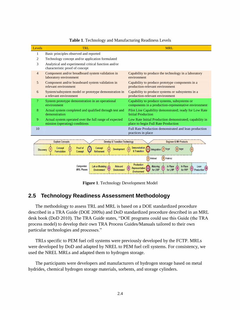
2.4
Table 1. Technology and Manufacturing Readiness Levels
Levels TRL MRL
1 Basic principles observed and reported
2 Technology concept and/or application formulated
3 Analytical and experimental critical function and/or
characteristic proof of concept
4 Component and/or breadboard system validation in
laboratory environment
Capability to produce the technology in a laboratory
environment
5 Component and/or brassboard system validation in
relevant environment
Capability to produce prototype components in a
production-relevant environment
6 System/subsystem model or prototype demonstration in
a relevant environment
Capability to produce systems or subsystems in a
production-relevant environment
7 System prototype demonstration in an operational
environment
Capability to produce systems, subsystems or
components in a production-representative environment
8 Actual system completed and qualified through test and
demonstration
Pilot Line Capability demonstrated; ready for Low Rate
Initial Production
9 Actual system operated over the full range of expected
mission (operating) conditions
Low Rate Initial Production demonstrated; capability in
place to begin Full Rate Production
10 Full Rate Production demonstrated and lean production
practices in place
Figure 1. Technology Development Model
2.5 Technology Readiness Assessment Methodology
The methodology to assess TRL and MRL is based on a DOE standardized procedure
described in a TRA Guide (DOE 2009a) and DoD standardized procedure described in an MRL
desk book (DoD 2010). The TRA Guide states, “DOE programs could use this Guide (the TRA
process model) to develop their own TRA Process Guides/Manuals tailored to their own
particular technologies and processes.”
TRLs specific to PEM fuel cell systems were previously developed by the FCTP. MRLs
were developed by DoD and adapted by NREL to PEM fuel cell systems. For consistency, we
used the NREL MRLs and adapted them to hydrogen storage.
The participants were developers and manufacturers of hydrogen storage based on metal
hydrides, chemical hydrogen storage materials, sorbents, and storage cylinders.

2.5
Procedure for TRL/MRL TRA:
1. PNNL sent out requests for TRA self-assessments by e-mail
a. to SNL/NREL Early Market workshop participants
b. using existing network
2. Technology developers and manufacturers performed self-assessments and assigned TRL
and MRL for their hydrogen storage technologies
3. PNNL recorded TRL and MRL levels and identified Risk Elements
a. verified that Risk Element replies are consistent
4. PNNL requested validation of TRL and MRL levels
a. confirmation of assigned TRL and MRL
b. confirmation of lowest/highest MRL/Risk Element
5. Summarized TRL and MRL levels
a. tables with overall TRL and MRL for each hydrogen storage technology
6. Conclusions and Recommendations
2.6 TRA Questionnaires and Validation
Requests to participate in this study and to perform a self-assessment were sent out by e-mail
to identified hydrogen storage technology developers and manufacturers. The TRA questionnaire
was attached with an instruction to answer Yes or No to all questions for each hydrogen storage
technology. The participant was also informed that the self-assessment would be treated
anonymously. No collected information was to be connected with a specific company in the
report. The results were grouped together for each technology and application.
With replies to all questions, the TRL and MRL/Risk Element could be identified. The
questionnaire, attached in the Appendix, consisted of two parts:
Table A.1: Technology Readiness Level for Hydrogen Storage Technologies
Table A.2: Manufacturing Readiness Level for Hydrogen Storage Technologies with
questions to identify Risk Elements
After obtaining the replies from the participants who performed the self-assessment, PNNL
collected the data and analyzed it. It appeared that the replies to the MRL questions were not
always consistent. For example, a respondent might have replied with “No” to a Risk Element
question at MRL 4, but “Yes” at MRL 5. Inconsistency was typical for the participants who were
not accustomed to TRL/MRL definitions. Validation of assigned TRL/MRL was therefore
necessary.

2.6
After evaluating the responses, a follow up e-mail was sent out to validate the replies. A
request for permission to release their participation and their company information was also
included with a note that the provided TRL/MRL would not be tied to a specific company name.
For most of the participants, a simple confirmation of assigned TRL and MRL was enough. In a
few cases, more clarifications were needed when the highest Risk Element was unclear due to
inconsistencies in the replies.
One of the participants was interviewed on the phone by PNNL to validate the replies. One
participant performed the TRA while in the same location as the PNNL Principal Investigator
and validation was therefore immediately performed.
Three replies were not validated due to participants not responding to the request; however,
the assigned MRLs did not change the overall results and were therefore included.
The TRL/MRL data was gathered by PNNL for each hydrogen storage technology based on
materials group, (i.e. metal hydride, chemical hydrogen storage material, sorbent and storage
cylinder) and also for each early market technology.
3.1
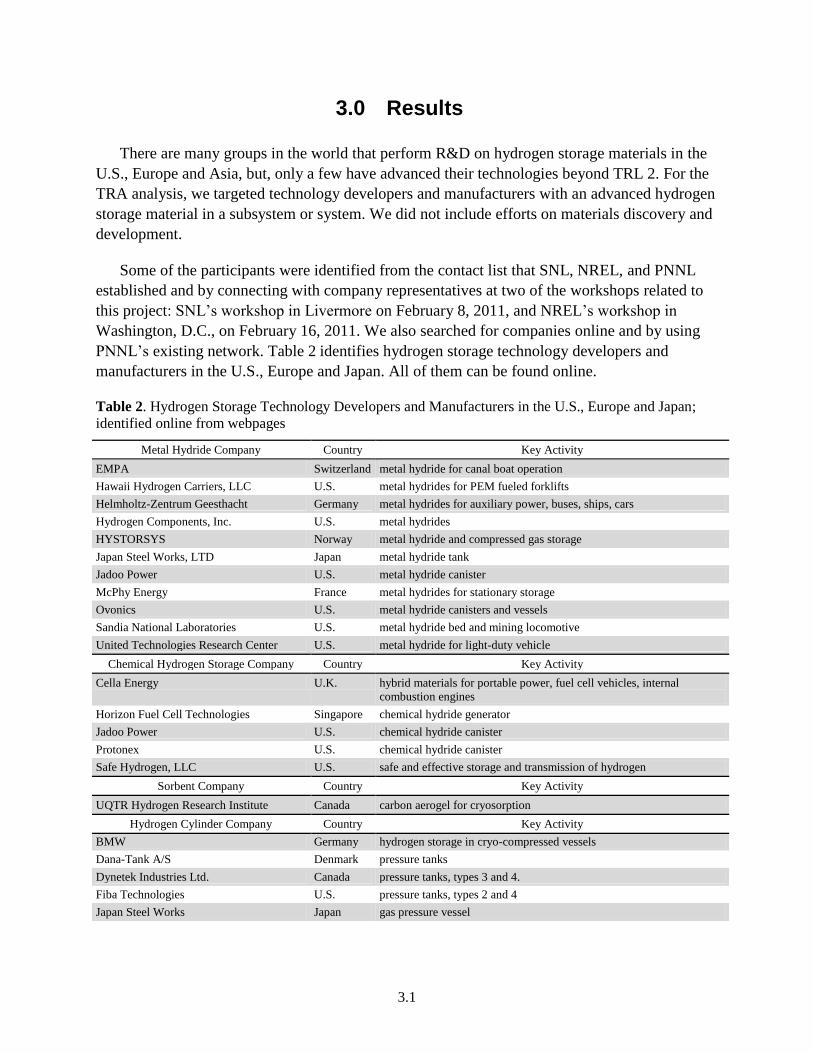
3.0 Results
There are many groups in the world that perform R&D on hydrogen storage materials in the
U.S., Europe and Asia, but, only a few have advanced their technologies beyond TRL 2. For the
TRA analysis, we targeted technology developers and manufacturers with an advanced hydrogen
storage material in a subsystem or system. We did not include efforts on materials discovery and
development.
Some of the participants were identified from the contact list that SNL, NREL, and PNNL
established and by connecting with company representatives at two of the workshops related to
this project: SNL’s workshop in Livermore on February 8, 2011, and NREL’s workshop in
Washington, D.C., on February 16, 2011. We also searched for companies online and by using
PNNL’s existing network. Table 2 identifies hydrogen storage technology developers and
manufacturers in the U.S., Europe and Japan. All of them can be found online.
Table 2. Hydrogen Storage Technology Developers and Manufacturers in the U.S., Europe and Japan;
identified online from webpages
Metal Hydride Company Country Key Activity
EMPA Switzerland metal hydride for canal boat operation
Hawaii Hydrogen Carriers, LLC U.S. metal hydrides for PEM fueled forklifts
Helmholtz-Zentrum Geesthacht Germany metal hydrides for auxiliary power, buses, ships, cars
Hydrogen Components, Inc. U.S. metal hydrides
HYSTORSYS Norway metal hydride and compressed gas storage
Japan Steel Works, LTD Japan metal hydride tank
Jadoo Power U.S. metal hydride canister
McPhy Energy France metal hydrides for stationary storage
Ovonics U.S. metal hydride canisters and vessels
Sandia National Laboratories U.S. metal hydride bed and mining locomotive
United Technologies Research Center U.S. metal hydride for light-duty vehicle
Chemical Hydrogen Storage Company Country Key Activity
Cella Energy U.K. hybrid materials for portable power, fuel cell vehicles, internal
combustion engines
Horizon Fuel Cell Technologies Singapore chemical hydride generator
Jadoo Power U.S. chemical hydride canister
Protonex U.S. chemical hydride canister
Safe Hydrogen, LLC U.S. safe and effective storage and transmission of hydrogen
Sorbent Company Country Key Activity
UQTR Hydrogen Research Institute Canada carbon aerogel for cryosorption
Hydrogen Cylinder Company Country Key Activity
BMW Germany hydrogen storage in cryo-compressed vessels
Dana-Tank A/S Denmark pressure tanks
Dynetek Industries Ltd. Canada pressure tanks, types 3 and 4.
Fiba Technologies U.S. pressure tanks, types 2 and 4
Japan Steel Works Japan gas pressure vessel

3.2
Table 2. (contd)
Hydrogen Cylinder Company (contd) Country Key Activity
JFE Container Co, Ltd., Japan Japan gas pressure vessel
Lincoln Composites U.S. hydrogen storage in high-pressure cylinders
Lawrence Livermore National Laboratory U.S. hydrogen storage in cryo-compressed vessels
Luxfer Gas Cylinders U.S. pressure vessels, composites, type 3
Profile Composites Inc. Canada rapid manufacturing of vehicle-scale, carbon-composite, high-pressure
hydrogen storage cylinders
Samtech Corporation Japan high-pressure tanks
Structural Composites Industries, Inc. U.S. gas pressure vessels
Quantum Fuel System Technologies
Worldwide, Inc.
U.S. manufacturing technologies for low-cost hydrogen storage vessels
Other Country Key Activity
Digital Wave Corporation U.S. nondestructive ultrasonic scanning technology
SiGNa Chemistry, Inc. U.S. sodium silicide (NaSi) hydrogen generation system
Powdermet, Inc. U.S. high-strength, low-cost microballoons for hydrogen storage
The technology readiness self-assessment forms for TRL and MRL assignments were sent
out to identified hydrogen storage technology developers and manufacturers, both domestic and
international organizations, including U.S. national laboratories, U.S. companies, European
companies and Japanese companies. Out of 32 requests for self-assessments, 25 invitees
participated and 22 of the replies were validated. The requests for participation were sent out by
e-mail during Summer/Fall 2011 and the TRA analysis was performed in Winter/Spring 2011.
The results can be grouped based on hydrogen storage material or application. The replies
per materials technology were:
metal hydrides: 12 replies; 9 validated
chemical hydrogen storage materials: 3 replies; 3 validated
sorbents: 1 reply; 1 validated
hydrogen storage cylinders: 9 replies; 9 validated
Below follows PNNL’s TRA analysis of each hydrogen storage technology and intended
application. The overall MRLs, i.e. lowest MRL/Risk Element with all questions replied
positively, are provided for all participants in Tables 3−6.
3.1 Metal Hydrides TRA Analysis
Metal hydrides’ (MH) technical maturity, based on 12 replies, is between TRLs 3 and 9,
which indicates that there are metal hydride materials with advanced maturity and that are ready
for commercialization, but also materials that need further development before system
validation. The manufacturing readiness is between MRLs 3 and10, which tells us that the MH
technologies’ manufacturing process has been developed for certain applications and that LRIP
and even FRP are in progress. The TRLs and MRLs assigned by all participants are given in
Table 3.

3.3
If comparing research institute developers with companies that have a product, it appears that
the companies have considerably higher MRLs of 7−10, while developers at research institutes
have MRLs 3−4. Another difference to note is that the companies are using intermetallic
compound MHs, while the research institutes are using complex MHs.
The participating companies did not reveal the compositions of their advanced MHs. The
research institutes revealed which complex MHs they are developing, i.e. NaAlH4, MgH2+LiBH4
and a high-temperature metal hydride, MgH2. Metal hydrides operating at low temperatures
(< 100°C), such as of LaNi5-based alloys, are used for MHE and they tend to be heavier, which
is a benefit for certain applications such as forklifts where the MH material balances the weight.
Table 3. MRLs for Metal Hydride-Based Technologies
MRLs for Metal Hydrides Companies’ Self-Assessment
Risk Element High Low
Technical Maturity (TRL) 9 3
Design 10 4
Materials 10 3
Cost & Funding 10 3
Process Capability & Controls 10 3
Personnel 10 3
Facilities 10 3
Manufacturing Planning, Scheduling, Control 10 3
The participants provided the following intended applications for MHs:
material handling equipment
portable applications
stationary storage
storage for both high-pressure and low-pressure needs
auxiliary power units
mobile/vehicular applications
Below, the TRL and MRL for each application are provided with details regarding identified
Risk Elements.
MHE Applications: TRL 7−9 was given by two participants (one was validated). Thus,
integrated systems have been demonstrated in an operationally relevant environment, and
although systems development is not completely finalized, the technology has been proven to
work in final form by at least one company in the U.S. MRL 4 was given, which is the lowest
MRL required for production readiness and to start transitioning a technology into LRIP.
Looking into the Risk Elements, Design and Materials were both assigned MRL 6−7 and are
thus not the limiting factor to starting LRIP. Cost & Funding has MRL 5−6, Process Capability
has MRL 3, Personnel has MRL 3−5, Facilities has MRL 3−5, and Manufacturing Planning has
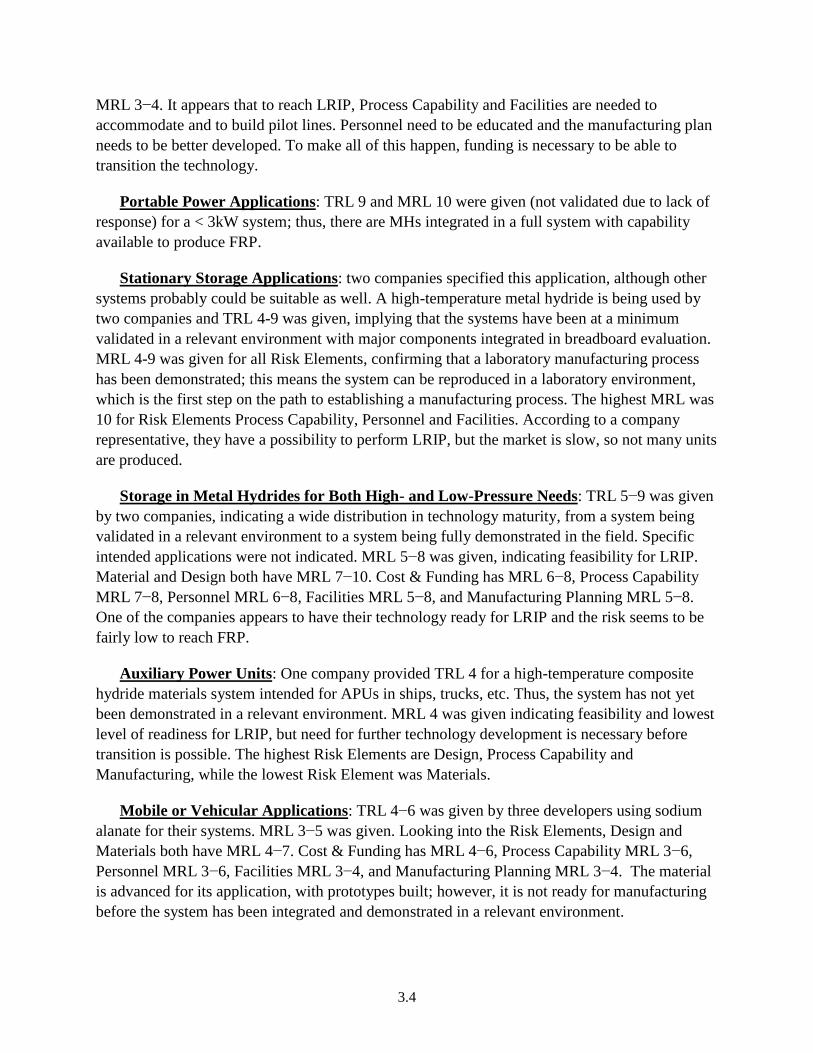
3.4
MRL 3−4. It appears that to reach LRIP, Process Capability and Facilities are needed to
accommodate and to build pilot lines. Personnel need to be educated and the manufacturing plan
needs to be better developed. To make all of this happen, funding is necessary to be able to
transition the technology.
Portable Power Applications: TRL 9 and MRL 10 were given (not validated due to lack of
response) for a < 3kW system; thus, there are MHs integrated in a full system with capability
available to produce FRP.
Stationary Storage Applications: two companies specified this application, although other
systems probably could be suitable as well. A high-temperature metal hydride is being used by
two companies and TRL 4-9 was given, implying that the systems have been at a minimum
validated in a relevant environment with major components integrated in breadboard evaluation.
MRL 4-9 was given for all Risk Elements, confirming that a laboratory manufacturing process
has been demonstrated; this means the system can be reproduced in a laboratory environment,
which is the first step on the path to establishing a manufacturing process. The highest MRL was
10 for Risk Elements Process Capability, Personnel and Facilities. According to a company
representative, they have a possibility to perform LRIP, but the market is slow, so not many units
are produced.
Storage in Metal Hydrides for Both High- and Low-Pressure Needs: TRL 5−9 was given
by two companies, indicating a wide distribution in technology maturity, from a system being
validated in a relevant environment to a system being fully demonstrated in the field. Specific
intended applications were not indicated. MRL 5−8 was given, indicating feasibility for LRIP.
Material and Design both have MRL 7−10. Cost & Funding has MRL 6−8, Process Capability
MRL 7−8, Personnel MRL 6−8, Facilities MRL 5−8, and Manufacturing Planning MRL 5−8.
One of the companies appears to have their technology ready for LRIP and the risk seems to be
fairly low to reach FRP.
Auxiliary Power Units: One company provided TRL 4 for a high-temperature composite
hydride materials system intended for APUs in ships, trucks, etc. Thus, the system has not yet
been demonstrated in a relevant environment. MRL 4 was given indicating feasibility and lowest
level of readiness for LRIP, but need for further technology development is necessary before
transition is possible. The highest Risk Elements are Design, Process Capability and
Manufacturing, while the lowest Risk Element was Materials.
Mobile or Vehicular Applications: TRL 4−6 was given by three developers using sodium
alanate for their systems. MRL 3−5 was given. Looking into the Risk Elements, Design and
Materials both have MRL 4−7. Cost & Funding has MRL 4−6, Process Capability MRL 3−6,
Personnel MRL 3−6, Facilities MRL 3−4, and Manufacturing Planning MRL 3−4. The material
is advanced for its application, with prototypes built; however, it is not ready for manufacturing
before the system has been integrated and demonstrated in a relevant environment.

3.5
In summary, the metal hydride technologies’ high TRLs and MRLs indicate that there is
great potential for early market applications. There are advanced MHs available and integrated
systems ready for LRIP with needs for developing Process Capability and Facilities to establish
manufacturing. The complex MHs have lower maturity and need a technology development
effort to advance toward LRIP.
3.2 Chemical Hydrogen Storage Materials TRA Analysis
The chemical hydrogen storage materials’ technical maturity, based on three validated
replies, is between TRL 3 and 5 for three different materials, i.e. magnesium hydride slurry,
ammonia borane and sodium borohydride. Prototypes have been demonstrated and one of the
technologies has been integrated in breadboard evaluation. The manufacturing readiness is low at
MRL 2, indicating that the manufacturing concept has been defined but not developed. The Risk
Elements for Design, Materials and Cost & Funding are at MRL 4, which indicates the lowest
manufacturing readiness to reach LRIP. Process Capability, Personnel, Facilities and
Manufacturing Planning are at MRL 2, which is low relative to the technical maturity. The
MRLs for chemical hydrides are summarized in Table 4.
The participants provided the following intended applications for chemical hydrogen storage
materials:
portable power
storage of hydrogen for various applications
emergency power
In summary, there are chemical hydrogen storage canisters available for one-use/disposable
applications and for portable and emergency power; however, there are no manufacturing
processes in place. Before reaching LRIP, integrated systems need to be demonstrated to
transition the technologies.
Table 4. MRLs for Chemical Hydrogen Storage-Based Technologies
MRLs for Chemical Hydrides Companies’ Self-Assessment
Risk Element High Low
Technical Maturity (TRL) 6 3
Design 7 2
Materials 9 2
Cost & Funding 8 2
Process Capability & Controls 8 2
Personnel 7 2
Facilities 8 2
Manufacturing Planning, Scheduling, Control 6 2
3.6
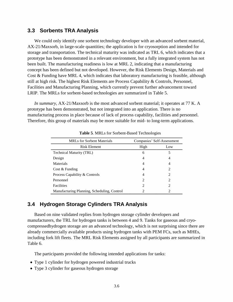
3.3 Sorbents TRA Analysis
We could only identify one sorbent technology developer with an advanced sorbent material,
AX-21/Maxsorb, in large-scale quantities; the application is for cryosorption and intended for
storage and transportation. The technical maturity was indicated as TRL 6, which indicates that a
prototype has been demonstrated in a relevant environment, but a fully integrated system has not
been built. The manufacturing readiness is low at MRL 2, indicating that a manufacturing
concept has been defined but not developed. However, the Risk Elements Design, Materials and
Cost & Funding have MRL 4, which indicates that laboratory manufacturing is feasible, although
still at high risk. The highest Risk Elements are Process Capability & Controls, Personnel,
Facilities and Manufacturing Planning, which currently prevent further advancement toward
LRIP. The MRLs for sorbent-based technologies are summarized in Table 5.
In summary, AX-21/Maxsorb is the most advanced sorbent material; it operates at 77 K. A
prototype has been demonstrated, but not integrated into an application. There is no
manufacturing process in place because of lack of process capability, facilities and personnel.
Therefore, this group of materials may be more suitable for mid- to long-term applications.
Table 5. MRLs for Sorbent-Based Technologies
MRLs for Sorbent Materials Companies’ Self-Assessment
Risk Element High Low
Technical Maturity (TRL) 6 5
Design 4 4
Materials 4 4
Cost & Funding 4 2
Process Capability & Controls 4 2
Personnel 2 2
Facilities 2 2
Manufacturing Planning, Scheduling, Control 2 2
3.4 Hydrogen Storage Cylinders TRA Analysis
Based on nine validated replies from hydrogen storage cylinder developers and
manufacturers, the TRL for hydrogen tanks is between 4 and 9. Tanks for gaseous and cryo-
compressedhydrogen storage are an advanced technology, which is not surprising since there are
already commercially available products using hydrogen tanks with PEM FCs, such as MHEs,
including fork lift fleets. The MRL Risk Elements assigned by all participants are summarized in
Table 6.
The participants provided the following intended applications for tanks:
Type 1 cylinder for hydrogen powered industrial trucks
Type 3 cylinder for gaseous hydrogen storage

3.7
Type 4 cylinder for gaseous hydrogen storage
cryogenic pressure vessel for vehicles
high-pressure storage
Gaseous hydrogen storage readiness is higher for low-pressure applications than for high-
pressure ones, and if refill stations are implemented, this technology is ready to be integrated into
appropriate early market applications when volumetric density is not an issue. FRP is feasible as
indicated by MRL 8−10, and with higher demand, production rates would be increased.
One of the participants is using a 1 kg gas Type 1 steel cylinder for a hydrogen powered
industrial truck (HPIT), and TRL 9, MRL 7 were given. Regarding Risk Elements: Facilities and
Manufacturing both have TRL 6. The technology has been demonstrated in the field, but the
manufacturing process is not fully implemented, although close to being ready for LRIP.
Type 3 cylinders have TRL 8−9 and MRL 5−8 as provided by two participants. Regarding
Risk Elements: Design has MRL 7−10, Materials has MRL 5−10, Cost & Funding has MRL
9−10, Process Capability has MRL 7−10, Personnel has MRL 5−10, Facilities is at MRL 9−10
and Manufacturing Planning has MRL 5-9.
Type 4 cylinders have TRL 4−5 and MRL 4−5 as provided by two participants. Regarding
Risk Elements: Design has MRL 4−7, Materials has MRL 4−7, Cost & Funding has MRL 4−7,
Process Capability has MRL 4−7, Personnel has MRL 4−5, Facilities has MRL 4−6, and
Manufacturing Planning is at MRL 4.
Cryo-compressed hydrogen storage has TRL 5−6 as given by two participants with
systems validated in relevant environments and one prototype demonstration integrated in the
application. The intended application is on-board vehicles. MRL 4−5 was given, indicating a low
level of readiness for LRIP. Design and Materials both have MRL 5−6. Cost & Funding has
MRL 5−6, Process Capability has MRL 4−5, Personnel has MRL 5, Facilities has MRL 4 and
Manufacturing Planning is at MRL 4. This technology is thus not quite ready for transition to
LRIP and needs further technology development along with implementation of manufacturing
planning.
In summary, there are gaseous hydrogen storage cylinders of Type 3 developed to TRL 8−9
and MRL 5−8; thus, LRIP is feasible and even implemented and commercially available. The
pressure vessel technology is suitable for early market applications, especially motive
applications. The Type 4 cylinders are less developed at TRL 4−5 and MRL 4−5 and need
technical advancements to proceed toward LRIP. Moreover, the costs of materials need to be
reduced. It appears that the companies have ongoing LRIP, but not FRP. As one manufacturer
said: “If there would be enough demand from customers, we could make 10,000 per year, or as
many as needed.”

3.8
Table 6. MRLs for Hydrogen Storage Cylinders
MRLs for Hydrogen Cylinders
(Gaseous And Liquid Hydrogen) Companies’ Self-Assessment
Risk Element High Low
Technical Maturity (TRL) 9 4
Design 10 5
Materials 10 6
Cost & Funding 9 3
Process Capability & Controls 10 5
Personnel 10 5
Facilities 10 4
Manufacturing Planning, Scheduling, Control 9 3

4.1
4.0 Summary and Conclusions from Technology and Manufacturing Readiness Assessment
PNNL performed a technology and manufacturing readiness assessment based on existing
DOE TRA and MRA procedures adapted for hydrogen storage technologies to learn the current
readiness of existing hydrogen storage technologies for early market applications. The
manufacturing status could be established from eight Risk Elements: Technical Maturity,
Design, Materials, Cost & Funding, Process Capability, Personnel, Facilities and Manufacturing
Planning.
PNNL assisted in identifying candidates for the self-assessments, providing a questionnaire
to company points of contact, and collected the data. The replies were validated and the data was
analyzed to establish the status of hydrogen storage technologies based on given TRL/MRL. The
replies were anonymous and the established TRL/MRL is not tied to any company name.
The following key conclusions on hydrogen storage technology maturity could be made
based on the TRA analysis:
1. The highest TRLs for existing technologies are for MHs with TRL 7−9 and gaseous storage
with TRL 8−9; these are most promising for early markets.
2. For MHs, the highest Risk Elements for Manufacturing Readiness were identified as Process
Capability, Facilities and Manufacturing Planning.
3. Integration of metal hydrides in motive applications is underway, specifically MHE
applications, i.e. forklifts, in several global demonstration and deployment projects.
4. Materials development programs are needed to replace the expensive rare-earth metal
hydrides typically used in MHE applications with low-cost, abundant metals.
5. For compressed gas storage and Type 3 Cylinders, the highest Risk Elements for
Manufacturing Readiness were identified as Personnel and Manufacturing Planning.
6. Hydrogen Storage Cylinders (Types 1 and 3) have been demonstrated in relevant
environments for compressed gas storage and LRIP is in progress, ready for FRP if demand
increases. Funded efforts to decrease cost are already in progress.
7. Cryo-compressed hydrogen storage has TRL 5−6 with systems validated in relevant
environments and one prototype demonstration integrated in the application. The intended
application is on-board vehicles. MRL 4−5 was given, indicating a low level of readiness for
LRIP.
8. Metal hydrides for stationary storage of APUs could also have an impact on early markets,
but systems integration efforts would be necessary as a first stage.
9. Chemical hydrogen storage canisters/cartridges are to a limited extent commercially
available for non-motive applications, especially portable power, but market demand is low
and technology transition programs are recommended.
4.2
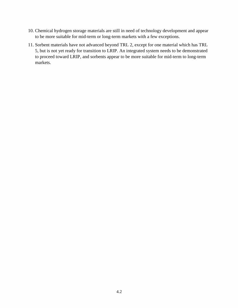
10. Chemical hydrogen storage materials are still in need of technology development and appear
to be more suitable for mid-term or long-term markets with a few exceptions.
11. Sorbent materials have not advanced beyond TRL 2, except for one material which has TRL
5, but is not yet ready for transition to LRIP. An integrated system needs to be demonstrated
to proceed toward LRIP, and sorbents appear to be more suitable for mid-term to long-term
markets.

5.1
5.0 Recommendations
Based on the TRA analysis with assignments of TRL and MRL of hydrogen storage
technologies based on MHs, chemical hydrogen storage materials, sorbent materials and
hydrogen storage cylinders, and also specific applications, the following programmatic
recommendations are made.
Metal hydrides are identified to have the greatest impact on the early markets for MHE and
GSE, such as fork lifts and trucks, provided that funds are provided for systems integration,
demonstration and deployment in relevant environments and this is a recommended area for
DOE support.
To reach early commercialization of advanced metal hydride-based technologies, focus needs
to be on Process Capability, Facilities and Manufacturing Planning to reach LRIP and market
and technology transformation programs are recommended.
Chemical hydrogen storage materials are identified to have greatest impact on the early
market for portable power and consumer electronics if using one-use cartridges for disposal
or recycling. Only a few products are commercially available, main reason due to low
consumer demand. It is recommended that DOE supports technology transition programs to
advance the technology and lower cost. An infrastructure program to implement solutions for
recycle systems would bring cost down and provide the user with a familiar system similar to
that for batteries.
Many chemical hydrogen storage materials and complex MHs show promise for
commercialization, but may realistically be for mid-term to long-term markets since
materials development is still in progress and is therefore not recommended for early market
demonstrations, rather materials and technology development programs.
Sorbent materials are more suitable for mid-term to long-term markets since an integrated
system has not yet been demonstrated. To advance toward LRIP, a technology program to
demonstrate an integrated system is needed and focus needs to be on Process Capability &
Controls, Personnel, Facilities and Manufacturing Planning.
Gaseous hydrogen storage cylinders are already commercially available for a variety of
applications, but demand is low. Therefore, a market transformation program would help
increase demand for FCs and hydrogen storage.
Infrastructure for hydrogen refueling is a concern for hydrogen storage technology
manufacturers and it is necessary to increase the efforts to provide an infrastructure and DOE
support is recommended.
This study was aimed at hydrogen storage for fuel cell applications; however, it was revealed
that hydrogen storage is also used in other technologies, such as heat exchangers and thermal
energy storage that are viable technologies in need of support by DOE to be further
developed and integrated in the hydrogen infrastructure.

5.2
It is important to routinely perform TRA/MRA analysis of hydrogen storage technologies in
parallel with the ongoing TRA/MRA analysis of FCs, to monitor progress and to identify
gaps and R&D needs. It is recommended that an ongoing TRA/MRA activity on hydrogen
storage technologies is established and that participation in this activity is a requirement for
all co-funded demonstration activities.
6.1
6.0 References
DoD – U.S. Department of Defense. 2010. Manufacturing Readiness Level Deskbook,
Department of Defense Manufacturing Technology Program. July 30, 2010. U.S. Department of
Defense, Washington, D.C. Accessed March 2, 2012, at
http://www.dodmrl.com/MRL_Deskbook_30_July_2010.pdf.
DOE − U.S. Department of Energy. 2009a. U.S. Department of Energy Technology Readiness
Assessment Guide, DOE G 413.3-4, 10-12-09. U.S. Department of Energy, Washington, D.C.
Accessed March 6, 2012, at https://www.directives.doe.gov/directives/0413.3-EGuide-04a/view.
DOE − U.S. Department of Energy. 2009b. Hydrogen Storage. DOE Energy Efficiency and
Renewable Energy. U.S. Department of Energy, Washington, D.C. Accessed March 2, 2012 at
http://www1.eere.energy.gov/hydrogenandfuelcells/storage/. Updated April 3, 2009.
DOE − U.S. Department of Energy. 2011a. The Department of Energy Hydrogen and Fuel Cells
Program Plan − An Integrated Strategic Plan for the Research, Development and
Demonstration of Hydrogen and Fuel Cell Technologies. September 2011. U.S. Department of
Energy, Washington, D.C. Accessed March 2, 2012 at
http://www.hydrogen.energy.gov/pdfs/program_plan2011.pdf.
DOE − U.S. Department of Energy. 2011b. Pathways to Commercial Success: Technologies and
Products Supported by the Fuel Cell Technologies Program. DOE Energy Efficiency and
Renewable Energy. U.S. Department of Energy, Washington, D.C. September, 2011. Accessed
March 2, 2012 at http://www1.eere.energy.gov/hydrogenandfuelcells/pdfs/pathways_2011.pdf
DOE − U.S. Department of Energy. 2011c. 2010 Fuel Cell Technologies Market Report. June,
2011. U.S. Department of Energy, Washington, D.C. Accessed March 2, 2012, at
http://www1.eere.energy.gov/hydrogenandfuelcells/pdfs/2010_market_report.pdf.
Greene DL, KG Duleep, and G Upreti. 2011. Status and Outlook for the U.S. Non-Automotive
Fuel Cell Industry: Impacts of Government Policies and Assessment of Future Opportunities.
ORNL/TM-2011/101. Oak Ridge National Laboratory, Oak Ridge, TN. May, 2011. Accessed
March 2, 2012, at
http://www1.eere.energy.gov/hydrogenandfuelcells/pdfs/ornl_non_automotive_fuelcell.pdf.
Klebanoff, L, Pratt J, Johnson T, Arienti M, Shaw L, and Moreno M. 2012. Hydrogen Storage
Needs for Early Market Non-Motive Fuel Cell Applications. Sandia Report, SAND2012-1739,
Sandia National Laboratories, Livermore, CA. March 2012.
Kurtz, J, C Ainscough, L Simpson, and M Caton. 2012. Hydrogen Storage Needs for Early
Motive Fuel Cell Markets. NREL Technical Report. National Renewable Energy Laboratory.
Golden, CO.
6.2
Mahadevan, K, H Stone, J Zewatsky, A Thomas, K Judd, and P Paul. 2007. Identification and
Characterization of Near-Term Direct Hydrogen Proton Exchange Membrane Fuel Cell
Markets. April, 2007. Battelle Memorial Institute, Columbus, OH. Accessed March 2, 2012, at
http://www1.eere.energy.gov/hydrogenandfuelcells/pdfs/pemfc_econ_2006_report_final_0407.p
df
Wheeler D and M Ulsh. 2009. Manufacturing Readiness Assessment for Fuel Cell Stacks and
Systems for the Back-up Power and Material Handling Equipment Emerging Markets. Technical
Report NREL/TP-560-45406, May, 2009. National Renewable Energy Laboratory Golden, CO.
Accessed March 2, 2012, at http://www.nrel.gov/hydrogen/pdfs/45406.pdf

6.3
Appendix
Activities of Hydrogen Storage Technology Companies and Assessment Questions


A.1
Appendix
Activities of Hydrogen Storage Technology Companies and
Assessment Questions
A.1 Activities of Participating Hydrogen Storage Technology Companies
A.1.1 Metal Hydrides
HYSTORSYS
“Hydrogen Storage & Systems AS (HYSTORSYS) is a Norwegian developer and
manufacturer of efficient, safe, and sustainable hydrogen energy storage and compression
systems based on metal hydrides. In the development, particular focus is devoted to hydrogen
system solutions intended for autonomous and environmentally friendly energy production and
distribution from renewable energy sources. The company possesses more than 10 years of
expertise on hydrogen based stand-alone power systems (H-SAPS) including photovoltaics (PV),
PEM electrolysers (ELY), PEM fuel cells (FC), advanced hydrogen storage technologies such as
metal hydrides (MH), and balance of plant (BoP).
Institute for Energy technology (IFE) in Norway possesses long-term research experience on
MH, from fundamental understanding of hydrogen-metal interactions to their use in experimental
hydride-based energy systems. Based on this unique expertise and knowledge, Hydrogen
Storage & Systems (HYSTORSYS) was founded in 2005. Recently, HYSTORSYS and IFE ran
a project on development of efficient technologies for production of MH-materials for hydrogen
energy applications. Through this project, we optimized the alloy synthesis and modification
process resulting in the desired characteristics of the metal hydrides, which is of key importance
for making high-quality hydride-based devices in the end.”1
McPhy Energy
“McPhy’s storage systems are enabling a real breakthrough in merchant hydrogen
distribution and create a viable answer to the rising demand for energy storage. McPhy head
quarters is in France with representations in Italy, Germany, Japan, India, Spain and Brasil.
McPhy’s mission is to industrialize and commercialize an innovative solid-state hydrogen
storage technology that offers unique advantages compared to other hydrogen storage solutions.
About 100 kg a day of magnesium hydride can currently be produced. About 20 kg a day of
intermetallic type hydrides (LaNi5, FeTi etc) can be produced. Also magnetocaloric materials in
form of controlled metal hydride compositions of LaFeSi type is being produced.
1 Information from company home page, http://www.hystorsys.no/.

A.2
McPhy targets on-site stationary storage systems, initially for the merchant hydrogen market
and on a longer term, for the growing renewable energy industry. Industrial hydrogen production
is mainly from the steam reforming of natural gas and less often from more energy-intensive
hydrogen production methods like the electrolysis of water.”1
Sandia National Laboratories
“Sandia has established the Research, Engineering, and Applications Center for Hydrogen
(REACH) in the Livermore Valley Open Campus. REACH is focused on addressing hydrogen
materials and engineering challenges through international consortia consisting of the leading
research organizations and partners from around the world. The REACH program is organized in
the following areas:
Physics of hydrogen in materials – Our research develops an understanding of
reactions on surfaces, hydrogen transport in materials, embrittlement mechanisms,
deformation and fracture, and mechanism modeling of hydrogen in materials.
Engineering analysis – Our programs include codes and standards, life-cycle design
methodology development, and predictive simulation for component and system
behavior understanding.
Systems engineering – Our efforts provide a bridge between the research and the
product. We work with industrial partners such as automotive original equipment
manufacturers and technology companies to overcome barriers facing the
deployment of advanced hydrogen technologies.”2
United Technologies Research Center
“United Technologies Research Center (UTRC) actively contributes to the Hydrogen Storage
Engineering Center of Excellence (HSECoE) led by Savannah River National Laboratory
(SRNL). UTRC’s broad objectives mirror those of the HSECoE to advance hydrogen storage
system technologies toward the DOE Hydrogen Program’s 2015 storage targets. Outcomes of
this project will include: 1) a more detailed understanding of storage system requirements; 2)
development of higher performance and enabling technologies such as novel approaches to heat
exchange, on-board purification and compacted storage material structures; 3) component/system
design optimization for prototype demonstration. UTC Power, a unit of United Technologies
Corp. (New York Stock Exchange symbol: UTX), is an experienced and proven leader in
developing and producing fuel cells that generate clean and reliable power for buildings, transit
1 E-mail from Daniel Fruchart (McPhy Energy) to Ewa Ronnebro (Pacific Northwest National Laboratory), January
31, 2012.
2 E-mail from Terry Johnson (Sandia National Laboratories) to Ewa Ronnebro (Pacific Northwest National
Laboratory), November 23, 2011.

A.3
buses, automobiles, and space and marine applications. UTC Power is the only company in the
world with experience in all five major fuel cell technologies.”1
A.1.2 Chemical Hydrogen Storage Materials
Cella Energy Ltd.
“Cella Energy Limited has unique patented technology in safe, low-cost hydrogen storage
materials. Cella is a spin-off company from the U.K. government-funded Rutherford Appleton
Laboratory at Harwell, Oxford, U.K. (similar to a U.S. National Laboratory). The lead investor
in the company is Space Florida, an Independent Special District of the State of Florida, created
for the purposes of fostering the growth and development of a sustainable and world-leading
space industry in Florida. Cella has developed a method using coaxial electrospinning or
electrospraying to encapsulate chemical hydrides inside nanoporous polymer scaffolds. The
nano-scaffold increases the kinetics of hydrogen release and suppresses the release of impurities.
It can also protect the hydride from oxygen and moisture, making it possible to handle it in air.
The result is a scalable industrial process for making composite hydrogen storage materials that
can be handled safely and operate at low temperatures and pressures compatible either with fuel
cells or internal combustion engines. The materials are then fluidized, so that they can replace
gasoline with minimal changes to the existing fuel infrastructure and consumer experience, with
vehicle carbon emissions reduced or eliminated. Projected costs are to be competitive with
today’s fuel prices. Cella’s proof-of-concept work has used ammonia borane encapsulated in
polystyrene, but current development is focused on readily recyclable hydrides. Cella has a
facilities at RAL and at the NASA Kennedy Space Center in Florida.”2
Horizon Fuel Cell Technologies
“Horizon Fuel Cell Technologies was founded in Singapore in 2003 and currently owns 5
international subsidiaries, including a new subsidiary in the United States. Having started
commercialization with small and simple products while preparing for larger and more complex
applications, Horizon already emerged as the world's largest volume producer of commercial
micro-fuel cell products, serving customers in over 65 countries. In 2009, the team also began
Horizon Energy Systems, a separate company in Singapore which applies its ultra-light fuel cell
technologies for customers in Aerospace & Defense.
Horizon’s complete technology platform is comprised of three main parts: fuel cells and their
materials, hydrogen supply and hydrogen storage. This platform enables a variety of product
1 E-mail from Bart van Hassel (United Technologies Research Center) to Ewa Ronnebro (Pacific Northwest
National Laboratory), November 3, 2011.
2 E-mail from Arthur Lovell (Cella Energy) to Ewa Ronnebro (Pacific Northwest National Laboratory), November
1, 2011.
A.4
developments targeting commercial markets, both as Horizon products, as well as third party
branded products.
Today, Horizon is able to produce extremely compact, lightweight, PEM fuel cells at varying
degrees of complexity and performance, as well as deliver hydrogen storage and on-site
hydrogen generation solutions that are suitable for many specialty and mainstream applications,
including consumer electronics, portable power, educational solutions, stationary power, ultra-
light systems for military use, as well as electric mobility solutions.”1
Safe Hydrogen, LLC
“Safe Hydrogen, LLC, is developing a liquid storage medium for hydrogen storage and
transportation. This liquid medium stores hydrogen in metal hydrides suspended in oil. When the
hydrogen is created by the electrolysis of water, the suspension is storing electricity. The
suspension, also called a slurry, is stable for days to weeks, is pump able, and stores hydrogen at
ambient temperatures and pressures. When hydrogen is available to store, hydrogen and slurry
are pumped into a reactor designed for the specific hydrogen flow rate at which the hydrogen is
absorbed by the metal hydride. When hydrogen is needed from storage, the slurry is pumped into
a reactor designed for the hydrogen flow rate required. Safe Hydrogen is currently developing a
slurry using magnesium hydride. In the oil suspension, magnesium hydride slurry can be
transported by any liquid fuel system including tank truck, tank rail car, barge, or tanker.
Magnesium hydride slurry meets the Department of Transportation requirements as a non-
hazardous material. It can be stored using the conventional liquid fuel infrastructure.”2
A.1.3. Sorbents
Hydrogen Research Institute, Université du Québec à Trois-Rivières
“The Hydrogen Research Institute (HRI) of the Université du Québec à Trois-Rivières
(UQTR) was established in 1994. It is one of Canada's leading institutions in hydrogen research.
Our mission is to advance science and technology for the establishment of a sustainable energy
system using hydrogen particularly in the field of production, storage, safety and use. The
Hydrogen Research Institute is a multidisciplinary team of over 60 people having at its disposal
state-of-the-art equipment and laboratories.
The Institute is committed to excellence in research and development, to the training of
highly qualified personnel and to establish strong partnerships with hydrogen stakeholders
including industry, governments, and academia, national and international institutions.
1 E-mail from Daniel Urry (Horizon Fuel Cell Technologies) to Ewa Ronnebro (Pacific Northwest National
Laboratory), January 15, 2012. Horizon Fuel Cell Technologies website is http://www.horizonfuelcell.com.
2 E-mail from Andrew McClaine (Safe Hydrogen) to Ewa Ronnebro (Pacific Northwest National Laboratory),
November 16, 2011.

A.5
The research and development activities carried out at HRI extend from material science to
system development and technology demonstration. The Institute is particularly interested in the
development of advanced materials to address the technical gaps needed for commercially
competitive hydrogen energy systems, in performing fluid dynamics simulations of hydrogen
releases for safety, as well as the safety and lifetime analysis of new materials and hydrogen
energy systems.”1
A.1.4. Hydrogen Storage Cylinders
Dynetek Technologies
“Dynetek Industries and its 100% owned subsidiary Dynetek Europe GmbH manufacture and
develop the world's leading alternative energy fuel storage cylinders and systems. Our cylinder
technology powers the world's fleet of alternative energy vehicles. DyneCell® technology is the
clear winner in the race to reduce overall storage weight. DyneCell cylinders achieve two-to-
fourfold weight reductions over conventional designs, without compromising structural integrity
and quality. The DyneCell is recognized as the most lightweight and fastest filling product on the
market.
Dynetek's proprietary technology powers not only automobiles, buses and trucks the world
over, but also portable power and stationary product manufacturing plants - giving clients a
substantial edge in the race to cut environmental and energy costs.
The core technology of Dynetek fuel systems is the DyneCell® cylinder which is one of the
fastest filling cylinder on the market. The DyneCell lightweight composite cylinder is built from
a seamless 'thin wall' aluminum liner with a full carbon fibre overwrap. This ultra-lightweight
liner technology guarantees higher storage capacity making the DyneCell technology the clear
winner in the race to reduce overall storage weight. Dynetek works with many of the world's
largest OEMs in design, development and manufacture of leading edge storage capabilities for
compressed hydrogen for fuel cell and internal combustion engines.
Dynetek provides safe, certified and cost-effective hydrogen storage for automotive, transit
buses, stationary storage and bulk hauling applications in pressures ranging from 3000psi
(200bar) to 6500psi (450bar). Dynetek successfully developed a 12500psi (825bar) cylinder for
stationary storage applications to be used in conjunction with a 10000psi (700bar) onboard
storage system.”2
1 E-mail from Richard Chahine (Université du Québec à Trois-Rivières) to Ewa Ronnebro (Pacific Northwest
National Laboratory), November 2, 2011. Hydrogen Research Institute website is www.irh.uqtr.ca.
2 Information from website: http://www.dynetek.com/
A.6
Lincoln Composites
“Lincoln Composites, manufacturer of the TITAN™ and TUFFSHELL® tanks, is the
leading provider of natural gas and hydrogen storage and transport solutions to the alternative
fuel vehicle industry.
Today, Lincoln Composites operates one of the world’s most advanced facilities for
designing, testing and manufacturing composite pressure vessels. We have broadened our
services to include products for the Automotive, Transit, Industrial and Oil & Gas exploration
industries. Our products highlight our expertise in innovative technology, versatile production
and cost effectiveness. We use proprietary computer design programs, customized resins and a
thorough knowledge of reinforcement materials to achieve customer objectives. Lincoln
Composites diverse product line illustrates multi-faceted manufacturing versatility and ground
breaking accomplishment. Our core business area is high-pressure gas containment for products
such as Natural Gas and Hydrogen Vehicle Fuel Tanks, Bulk Gas Transportation Modules, Fuel
Storage Systems and Accumulators.”1
Lawrence Livermore National Laboratory
“Cryogenic pressure vessels are composed of a high-pressure inner vessel made of carbon-
fiber-coated metal (similar to those used for storage of compressed gas), a vacuum space filled
with numerous sheets of highly reflective metalized plastic (for high-performance thermal
insulation), and a metallic outer jacket. Cryogenic pressure vessels operate at low temperature
(down to 20 K) and are designed for high pressure (350 bar). H2 density at these conditions is
considerably higher (~2x) than for compressed H2, resulting in high capacity systems that meet
DOE 2015 targets for weight and volume. High H2 storage density also reduces the amount of
expensive materials (carbon fiber and metal) necessary to store any given amount of H2,
resulting in cost-effective systems that minimize ownership cost. Liquid hydrogen pumping
enables rapid (5 minute) refueling. Finally, cryogenic pressure vessels have compelling safety
advantages: outer vacuum jacket provides secondary protection and containment, and cryogenic
hydrogen has low expansion energy compared to compressed gas. Long-term (~10years) vacuum
stability (necessary for high-performance thermal insulation) is the key outstanding technical
challenge. High-temperature baking and custom getters are possible technical solutions.”2
Samtech Corporation, Ltd.
“Samtech Corporation is located in Japan and develops aluminum liners for high-pressure
hydrogen gas cylinders. We are using the latest and best technology to make progress toward the
commercialization of this product in the near future. By utilizing our proprietary design system
to achieve a highly integrated combination of our flow forming and spinning processes, we are
able to manufacture high-precision, lightweight aluminum liners for high-pressure gas cylinders.
1 Information from website http://lincolncomposites.com
2 E-mail from Salvador Aceves (Lawrence Livermore National Laboratory) to Ewa Ronnebro (Pacific Northwest
National Laboratory), December 24, 2011.
A.7
On top of this, we have developed filament winding technology that enables us to wrap the
cylinders in carbon fiber, and at present we are the only Japanese manufacturer to have its VH3
cylinders certified by KHK. We have succeeded in producing these difficult-to-manufacture,
high-strength aluminum liners in a way that allows us to make our liners lighter and less
expensive at the same time.”1
Quantum Technologies
“Quantum Technologies partners with the Boeing Company to build hybrid pressure vessels
that combine the usage of advanced fiber placement (AFP) and traditional filament winding for
weight and cost reduction. The Boeing Company manufactures the AFP portion of the vessels,
and Quantum handles the design, completes the build with filament winding, and tests the
pressure vessels. The advantage of AFP is the ability to reinforce the domes locally. When
reinforcing the domes, the fiber in the cylinder section of the vessel is not needed and is
considered as parasitic fiber. The savings can be significant, especially for vessels with long
cylinder sections. For manufacturability, all the AFP layers are designed to make up the first
layers of the vessels and form caps for easy installation onto the vessel ends. With the ability to
eliminate the parasitic fiber, vessel weight and cost are decreased to allow hydrogen and
compressed natural gas vehicles to be more cost competitive.”2
1 Information from website http://www.samtech.co.jp/.
2 E-mail from Patrick Lam (Quantum Fuel System Technologies Worldwide) to Ewa Ronnebro (Pacific Northwest
National Laboratory), November 28, 2011. Company web site is http://www.qtww.com/.

A.8
A.2 Questionnaire for Developers & Manufacturers of Hydrogen Storage Technologies as Part of a Fuel Cell System
Self-Assessment of Technology and Manufacturing Maturity
Manufacturer contact information
– Company name
– Point of Contact
– Phone
___________________________________________________________
Date when self-assessment was performed:
___________________________________________________________
Describe the intended application of the technology:
___________________________________________________________
Identify the hydrogen storage technology that is being assessed:
If multiple, please use separate forms for each technology.
___________________________________________________________
Your self-assessment will be treated anonymously. No collected information will be connected with a
specific company in the report. We will group the results together for each application. We ask that you
provide your contact information in order to be able to follow up with in-depth questions. Please let us
know if you have any questions.

A.9
Instructions for TRA Self-Assessment
Step 1. Assess a Technology Readiness Level, TRL, for your hydrogen storage technology by
answering all the top-level and sub-level questions in Table A.1 with Yes or No. If all sub-level
questions are answered with a Yes for the associated TRL, and at least one sub-level question for the
next highest TRL can be answered with a No, then the highest TRL with all Yes answers is assigned.
Step 2. Assess a Manufacturing Readiness Level, MRL, for your hydrogen storage technology by
answering all the questions in Table A.2 with Yes or No. All ‘Risk Element’ questions need to be
answered to assign an MRL for each Risk Element. To assign an overall MRL, all ‘Risk Element’
questions for that level need to be answered with Yes.
Step 3. Please e-mail (or Fax) the completed forms with replies to all questions and TRL and MRL
levels assigned for your identified hydrogen storage technologies.
– e-mail: [email protected]
– Fax: (509)-375-4448
Step 4. Validation of assigned TRL and MRL to confirm that approach and interpretation are
consistent across responders.

A.10
Table A.1. Technology Readiness Levels (TRL) for Hydrogen Storage Technologies
TRL Top-Level and Sub-Level Questions Yes/No
1 Has basic research with basic principles been observed and reported? Y N
2 Have applied research and technology concepts been formulated and has the invention
process started?
Y N
3 Has the concept been validated and proof of concept been demonstrated?
Concept validation has been achieved with demo of technical feasibility using
breadboard or brassboard implementations
Y N
Applied research and development continues Y N
Technology is incorporated into a first-generation component/process design Y N
Remaining technical barriers associated with moving the technology from lab data to
component/process development are defined
Y N
4 Has the component/subsystem been validated in a laboratory environment?
Prototyping implementation and testing have been demonstrated Y N
Integration of technology elements has been demonstrated Y N
Design, development and lab testing of technological components provide evidence that
applicable component/process performance targets may be attainable based on projected
or modeled systems
Y N
5 Has the system/subsystem/component been validated in a relevant environment?
Major components integrated in breadboard evaluation Y N
Technological components/process steps are integrated with supporting elements so that
the technology can be tested and verified in the lab
Y N
6 Has there been a system/subsystem model or prototype demonstration in a relevant environment?
Representative model or prototype system has been tested in a relevant environment Y N
Fully integrated system built, tested and verified. Results demonstrate that the
system/process will meet all targets at full scale
Y N
7 Has there been a prototype demonstration in an operation-relevant environment?
System prototype demonstrated in an operational environment Y N
Integrated test vehicle with collateral and ancillary systems completed Y N
Technology verified at semi-commercial/commercial scale. System completed and
qualified through test and demonstration
Y N
8 Has the system been completed and incorporated in a commercial design and proven through testing in an
operational environment?
End of system development Y N
Fully integrated operational hardware and software systems developed Y N
Technology proven to work in final form under real-world conditions Y N
System incorporated into commercial design Y N
9 Has the system successfully been demonstrated in the field?
Fully integrated operational hardware/software systems have been developed Y N
Actual application of the technology is in final form and demonstrated in the field Y N
All documentation has been completed Y N
Sustained engineering support is in place Y N

A.11
In Table A.2, the following ‘Risk Elements’ have in-depth questions for each MRL
Technical maturity (from Table A.1)
Design
Materials
Cost and Funding
Process Capability and Control
Personnel
Facilities
Manufacturing Planning, Scheduling and Control
Table A.2 Manufacturing Readiness Levels (MRLs) for Hydrogen Storage Technologies
MRL Top-Level and Risk Element Questions Yes/No
1 Has manufacturing feasibility been assessed? Y N
2 Has manufacturing concept been defined? Y N
3 Has manufacturing concept been developed? Y N
4 Has a laboratory manufacturing process been demonstrated?
Technical Maturity
TRL = 4 achieved Y N
Design
Component and hardware functional requirements established Y N
System design has low manufacturing risk Y N
Materials
Exotic/high cost materials identified and addressed Y N
Any material-related environmental issues have been identified Y N
Cost and Funding
Manufacturing cost drivers are identified Y N
Cost reduction plan in place (as necessary to meet cost objectives ) Y N
Process Capability and Control
The manufacturing state of the art is identified and remaining manufacturing process
needs identified (gap analysis) Y N
Pilot line build initiated Y N
Personnel
Personnel with required specialty skills are in place Y N
Facilities
Facilities are available consistent with proposed Low Rate Initial Production levels, or
facility build plans are in place Y N
Manufacturing Planning
Manufacturing strategy has been developed Y N
Critical schedule paths are identified Y N

A.12
Table A.2 (contd)
MRL Top-Level and Risk Element Questions Yes/No
5 Has the manufacturing process been developed?
Technical Maturity
TRL = 5 achieved Y N
Design
Component and hardware functional requirements established Y N
System design with changes still has low manufacturing risk Y N
Materials
Material standardization plan developed Y N
Environmental issues with materials are addressed or a plan is in place Y N
Cost and Funding
Manufacturing costs are estimated and being reviewed and revised Y N
Making progress in identifying component cost goals Y N
Process Capability and Control
Key manufacturing processes identified for pilot line Y N
Personnel
Personnel skills have been demonstrated on components in lab Y N
Facilities
Facility changes initiated that are consistent with proposed Low Rate Initial Production
levels Y N
Manufacturing Planning
Manufacturing plan is developed, working and being reviewed Y N
6 Has a critical manufacturing process been prototyped?
Technical Maturity
TRL = 6 achieved Y N
Design
Minimal design changes occurring, to improve manufacturability Y N
System design with changes still has low manufacturing risk Y N
Materials
Material standardization plan being used Y N
Materials are available in production quantities Y N
Environmental issues with materials are addressed Y N
Cost and Funding
Design path to cost goals is identified Y N
Detailed cost analysis is available Y N
Process Capability and Control
Production issues identified and major issues resolved Y N
Prototype process demonstrations are complete Y N
Personnel
Training program necessary for specialty skills completed Y N
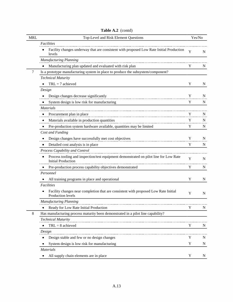
A.13
Table A.2 (contd)
MRL Top-Level and Risk Element Questions Yes/No
Facilities
Facility changes underway that are consistent with proposed Low Rate Initial Production
levels Y N
Manufacturing Planning
Manufacturing plan updated and evaluated with risk plan Y N
7 Is a prototype manufacturing system in place to produce the subsystem/component?
Technical Maturity
TRL = 7 achieved Y N
Design
Design changes decrease significantly Y N
System design is low risk for manufacturing Y N
Materials
Procurement plan in place Y N
Materials available in production quantities Y N
Pre-production system hardware available, quantities may be limited Y N
Cost and Funding
Design changes have successfully met cost objectives Y N
Detailed cost analysis is in place Y N
Process Capability and Control
Process tooling and inspection/test equipment demonstrated on pilot line for Low Rate
Initial Production Y N
Pre-production process capability objectives demonstrated Y N
Personnel
All training programs in place and operational Y N
Facilities
Facility changes near completion that are consistent with proposed Low Rate Initial
Production levels Y N
Manufacturing Planning
Ready for Low Rate Initial Production Y N
8 Has manufacturing process maturity been demonstrated in a pilot line capability?
Technical Maturity
TRL = 8 achieved Y N
Design
Design stable and few or no design changes Y N
System design is low risk for manufacturing Y N
Materials
All supply chain elements are in place Y N

A.14
Table A.2 (contd)
MRL Top-Level and Risk Element Questions Yes/No
Cost and Funding
Cost estimates are < 125% of cost goals and a detailed cost analysis is in place Y N
Program continues to make progress along path toward cost goals Y N
Process Capability and Control
Manufacturing processes have demonstrated acceptable yield at Low Rate Initial
Production levels Y N
Personnel
Specialty skills verified on pilot line Y N
Facilities
Facilities in place for Low Rate Initial Production Y N
Manufacturing Planning
Operating at Low Rate Initial Production rate Y N
9 Has low rate production been demonstrated?
Technical Maturity
TRL = 9 achieved Y N
Design
Design under configuration control Y N
Major design features stable and proven in test and evaluation Y N
Materials
All supply chain elements delivering materials and components Y N
Supply chain capable of Low Rate Initial Production schedules Y N
Full rate manufacturing materials needs are identified Y N
Cost and Funding
Low Rate Initial Production cost goals and production goals met or at < 110% of cost Y N
Cost model developed for full rate production Y N
Process Capability and Control
Low Rate Initial Production risks are being monitored Y N
Full rate process control concepts under development Y N
Personnel
Plans are in place for full rate production training Y N
Facilities
Facility upgrades to full rate production initiated Y N
Manufacturing Planning
Operating at Low Rate Initial Production rate Y N
Full rate production planning and control measures under development Y N
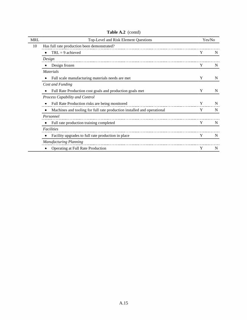
A.15
Table A.2 (contd)
MRL Top-Level and Risk Element Questions Yes/No
10 Has full rate production been demonstrated?
TRL = 9 achieved Y N
Design
Design frozen Y N
Materials
Full scale manufacturing materials needs are met Y N
Cost and Funding
Full Rate Production cost goals and production goals met Y N
Process Capability and Control
Full Rate Production risks are being monitored Y N
Machines and tooling for full rate production installed and operational Y N
Personnel
Full rate production training completed Y N
Facilities
Facility upgrades to full rate production in place Y N
Manufacturing Planning
Operating at Full Rate Production Y N
