technologies for mitigating tritium releases to the ... · technologies for mitigating tritium...
TRANSCRIPT
Technologies for MiTigaTing TriTiuM releases To The environMenT
LLE Review, Volume 103142
Historical BackgroundThe University of Rochester’s Laboratory for Laser Energet-ics is preparing to fabricate and implode targets containing DT ice. To minimize risk to the environment and personnel, a tritium-handling infrastructure has been installed within the laboratory. The infrastructure strives to intercept tritium emis-sions from the process loops and to reduce emissions arising from contaminated surfaces.
Historically, in the 1950s through the late 1960s, tritium-handling systems were housed in air-ventilated enclosures. Room air was drawn over the equipment, directed to a stack, and discharged. Tritium that escaped through leaks in the plumbing, desorbed from contaminated internal surfaces exposed to air, or was collected by vacuum systems would be entrained in the airflow and directed to the stack. There was no effort to extract the tritium species from the effluent stream. This practice was attractive because it was the least costly to implement, offered flexibility during upgrades and maintenance, and imposed the least number of constraints during routine operations. The facilities needed to be remote from populated areas, however, because the emissions imposed a significant impact on the environment surrounding the plants. While this approach offered short-term relief from tritium releases, over the longer term, the environment surrounding the facilities became severely contaminated. As a consequence, contamination levels within the facilities gradually rose and chronic worker dose increased. By the time the United States Atomic Energy Commission issued a directive (in 1969) to all tritium facilities to reduce effluents to levels “as low as practi-cal,” most large-scale tritium-handling facilities had already started to implement containment technologies.
To be successful and economically viable, the trapping and removal technologies had to be installed as near the point of origin as possible before any excessive dilution with air had occurred. In most cases, gaseous effluents were converted to water and collected on molecular sieves. The system through-puts, which were determined to first order by the sizes of the
Technologies for Mitigating Tritium Releases to the Environment
oxidation reactors and the driers, varied from a few liters/h to 2000 liters/min (LPM).
In the mid to late 1970s, efforts to replace air in the contain-ment boxes with inert gas were met with limited success. In this approach, tritium gas could be captured directly without conversion to tritium oxide by reacting with a titanium sponge. However, water vapor in the atmosphere would permeate into the boxes and passivate the sponge by forming an impenetrable oxide layer on the titanium. Systems containing fresh charges of titanium sponge would scavenge tritium from the inert gas for brief periods, but the performance would gradually degrade as the thickness of the oxide coating grew on the titanium. As a result, cleanup systems that collected tritium gas directly were reserved for special applications in which large quanti-ties of tritium gas were at risk and needed to be recovered without conversion to tritium oxide. More common, however, containment systems using either air or inert gas relied on the oxidation of all tritium species and the collection of the triti-ated water vapor with driers. Periodically, the driers could be regenerated to recover their effectiveness. The highly active condensate would be solidified and land disposed. In effect, tritium discharges that would have contaminated the environ-ment around a processing facility were collected on disposable beds and stored at burial sites in leak-tight containers.
The advent of new alloys comprising a mixture of iron and zirconium (Zr-Fe) dramatically broadened the options for tritium effluent treatment.1 The Zr-Fe alloy offered stability against passivation when exposed to impurity fluxes far supe-rior to that demonstrated by titanium sponge and, simultane-ously, offered the potential for recovering the captured tritium gas.2 Facilities that handled significant quantities of gas could recover and re-use tritium originally destined for the stack, and, as such, recoup some of their investment in the tritium while simultaneously reducing the cost of land-disposing solidified tritiated effluent. In the 1980s and 1990s, this alloy found utility not only in glovebox applications, but also in treating vacuum effluents.3 The acceptance of the alloy as a tritium-capture
Technologies for MiTigaTing TriTiuM releases To The environMenT
LLE Review, Volume 103 143
device has spread across the tritium community over the past two decades.4
Currently, an array of devices including Zr-Fe scavenger beds,5 uranium scavenger beds,6 molecular sieve driers, and nickel catalyst beds7 offers the potential to treat both inert gas and air streams.8 Both glovebox atmospheres and vacuum efflu-ent streams can be processed. These systems can be scaled over a broad range of throughputs and capacities, but, nevertheless, economic drivers continue to favor tritium recovery before any significant dilution with air occurs.9,10
By the mid-1970s, tritium became the dominant isotope for the radioluminescent industry, replacing both radium-226 and strontium-90. Tritium was viewed as radiologically safer and more environmentally acceptable by comparison to the other two isotopes. The industry appeared to be on the threshold of an unprecedented expansion with self-powered backlighting for digital watches leading a host of other ubiquitous applications. However, this optimistic growth was quickly tempered. The general tightening of environmental and safety regulations being applied to the nuclear industry spread to the radioluminescent industry. In part, this movement was driven by the Three Mile Island accident and the discovery of small amounts of tritium in a public school food-preparation facility across the street from a tritium light-manufacturing plant in Tucson, Arizona. By the 1980s the industry had stabilized, focusing on applications where absolute reliability was needed, such as in hospitals, mines, multilevel buildings, and aircraft exit markings. A number of military applications in which the benefit clearly outweighed the perceived risk have been identified and exploited.
Just as the optimism in the radioluminescent industry abated, fusion fuel needs for the magnetic confinement program spawned an intense, worldwide effort to identify materials suitable for tritium handling, techniques to purify and mea-sure tritium, and technologies to extract tritium from effluent streams. Significant advances were made in tritium-handling systems during the 1980s and 1990s.
This article reviews the technologies that minimize tritium releases from systems and discusses the strengths and weak-nesses of those options. To this end, the components and sys-tems that apply are reviewed, the optimal applications for those components and systems are identified, and their applicability to air and inert gas streams discussed.
The section entitled Guiding Principles (p. 143) reviews the guiding principles to consider when designing and operat-ing process and capture systems. Ignoring these principles could convert the capture equipment into emission sources. In Options for Tritium Capture (p. 144), capture options for both air-bearing and inert carrier streams are presented. Component selection and the rationale for selecting the order of the components are also discussed. Typical Tritium-Capture Schemes (p. 146) provides examples to illustrate the application of the guiding principles. Description of Components Used for Tritium Capture (p. 148) provides the salient performance features of the components discussed in the previous sections. Component throughputs are discussed in Throughput and Construction Guidelines (p. 153).
Guiding PrinciplesSeveral principles apply to the effective handling and cap-
ture of tritium. These include
• understanding the global requirement for tritium trapping,
• defense in depth,• interception close to the emission source,• circulation,• tailoring the capture system to the application,• monitoring all effluent streams, and• minimizing process volumes.
Each of these principles is discussed in the following para-graphs.
Many of the devices discussed in this article have demon-strated long-term effectiveness in mitigating tritium releases. However, these devices do not represent “magic bullets.” Their effectiveness depends heavily on the manner in which they are implemented and integrated into the process loops. To simply view these devices solely as “bolt-on” components will severely restrict their utility, reduce their effectiveness, or, in some cases, increase the potential for significant tritium releases. A holistic approach to trapping and containment is required. Careful evaluation of the intended application, the operating regime, and the composition of the effluent is required if the trapping and containment of the tritium in the effluent is to be effective and robust.
The defense-in-depth concept provides robustness. Layer-ing trapping technologies provide the opportunity for staged tritium recovery. Should the first barrier fail or perform below

Technologies for MiTigaTing TriTiuM releases To The environMenT
LLE Review, Volume 103144
design expectations, the second barrier can reduce the impact of the impending release.
Intercepting tritium emissions as close to their sources as possible continues to be the preferred option. The approach holds several advantages.
• The scale of the equipment and, consequently, its cost can be greatly reduced.
• Emissions in one subsystem do not impact the operation of other subsystems.
• Equipment can be tailored with greater precision to address specific potential release scenarios.
• Component selection options increase significantly if trapping occurs before mixing with air.
• The degree of secondary contamination is usually greatly reduced.
Circulating systems are preferred over once-through sys-tems. These systems provide more time to process tritiated effluent, increase the effective decontamination factor (DF) through the use of multiple passes, and permit monitoring of the efficiency of the trapping process. Operators can increase the processing time should the treated-gas activity remain unacceptably high. Additionally, they can temporarily stop the process to repair a defective component and then continue the treatment before releasing the gas to the environment.
Trapping and removal technology is most effective when designed for specific tasks. Additionally, technology effec-tiveness is enhanced when coupled with certain operating techniques. For example, lines and equipment should be evacuated repeatedly or flushed with inert gas or air and the effluent directed to the trapping system before proceeding with any dismantling. If feasible, air flushes should follow inert gas flushes to encourage the release of loosely bound tritium. Work should proceed in environments that are drier than the flush gas to minimize the moisture-stimulated release of tritium from surfaces. Plastic tents or temporary enclosures should be built around the equipment that will be maintained. The atmosphere from the tents or enclosures should be purged through the trap-ping system. Where routine maintenance is expected, separate maintenance gloveboxes with supporting trapping technology should be used to dismantle and decontaminate equipment. Materials, such as elastomeric O rings, have a high solubility for tritium and will release large quantities of tritium when removed from service. These items should be stored in small purged containers until they are packaged for land disposal.
Effluent from these containers may contain sufficient tritium to collect with trapping technologies.
All process exhausts should be monitored and, if necessary, treated before release to the stack. Typically, process exhausts represent the highest activity streams and make up the major-ity of the tritium chronically vented to the stack. The need for redundant isolation valves, or combinations of valves that are actuated by inline tritium monitors, should be reviewed. Where the potential for release is high, automated isolation valves should be installed.
Process loop volumes should be minimized, particularly in regions where tritium gas is susceptible to accidental release. Similarly, loop volumes that require frequent dismantling should be minimized. To achieve this, microwelding is pre-ferred to demountable fittings; smaller-diameter tubing is preferred over 1/2-in. tubing; and 1/4-in. bellows sealed valves are preferred over 1/2-in. valves. The use of close-fitted enclo-sures over vulnerable components is preferred over the use of larger, more conventional gloveboxes to reduce the amount of atmosphere that need to be processed. Such designs, in turn, reduce the scale of the trapping technology required. In high specific activity applications, inert gas is preferred over air as a purge gas. Tritium gas can be captured without conversion to oxide and recovered for re-use.
Options for Tritium CaptureThe tritium-capture technologies available for scrubbing
tritium from gaseous effluents fall into two categories: (1) those used to treat air or inert gas containing air, and (2) those used to treat inert gas streams. The devices used to process these gaseous effluent streams and their relative placement in the treatment train are illustrated in Figs. 103.25 and 103.26.
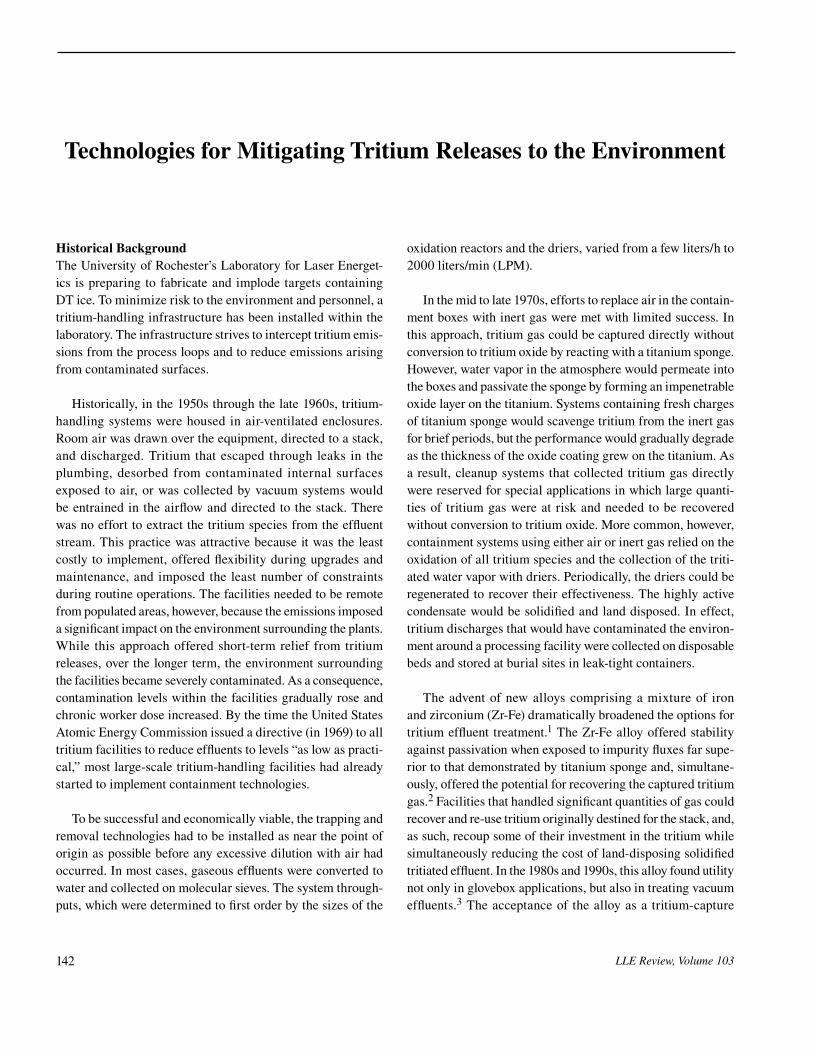
1. Air DetritiationElemental tritium can be readily converted to oxide with hot
copper oxide (CuO), Hopcalite,(a) or a precious metal catalyst (Pd, Pt, etc.). Tritiated organic vapors are more difficult to oxidize than elemental tritium. CuO reactors need to operate at 750°C to promote hydrocarbon oxidation efficiencies greater than 50% with a gas residence time(b) in the reactor exceeding 2 s. Hopcalite should be operated at 700°C to achieve complete oxidation of hydrocarbons at similar residence times. Palladium catalysts are more effective and achieve complete oxidation at 400°C. Occasionally, combinations of catalysts are used in the
(a)Hopcalite is a commercially available mixture of MnO2 and CuO.(b)Gas residence time is the time required for a slug of gas to transverse the
hot region of a reactor.
Technologies for MiTigaTing TriTiuM releases To The environMenT
LLE Review, Volume 103 145
E13167JRC
Air detritiation options
Low humidity stream High humidity stream
Oxidizer
Condenser
Collector
Drier
Monitor
Oxidizer
Drier
Monitor
<2°C dew point >2°C dew point
Figure 103.25Devices used in air detritiation schemes.
to tritiated water (HTO)(c) enters the drier directly. The gas temperature leaving the oxidizer has sufficient time to return to room temperature. As the flow rate increases, however, the oxidizer effluent must be cooled with an air-to-air heat exchanger to prevent heating the molecular sieve above room temperature. Drier capacity and performance degrades with increasing temperature. In high-humidity applications, a con-denser should be used to remove the bulk of the water vapor before directing the effluent stream to the drier. Drier capacity and performance also degrades with increasing water content in the drier.
Driers adsorb(d) tritiated water vapor on the molecular sieve. Approximately 7% water by weight can be loaded on the driers(e) before HTO breakthrough is observed. Dual-column drier systems permit continuous operation; while one drier is in service, the second can be regenerated.(f) Purging the drier during regeneration in the flow direction opposite to that used during the normal operation improves the performance of the drier because the exit end of the drier is never exposed to the high concentrations of HTO that are present at the drier inlet. Smaller systems may use a disposable drying column to eliminate the need for regeneration and packaging the desorbed water for land disposal. These driers can be outfitted with high-integrity, quick-disconnect fittings to minimize effluent releases during replacement.
The detritiation schemes for the high- and low-humidity effluent streams are illustrated in Fig. 103.25. A dew point of 2°C typically distinguishes the boundary between the two humidity regimes. When the water vapor concentration in the effluent exceeds 2°C (of the order of 0.7% water content by volume in the carrier), water can be condensed out of the effluent stream on a chilled surface and collected in a tank. The attractiveness of the condensation step increases as the humidity in the effluent increases because the drier operating time between regenerations can be optimized by capping the dew point of the effluent entering the drier at or near 2°C.
E13168JRC
Inert gas detriation options
Drier
Nickel
Uranium
Monitor
Zr-Fe
Monitor
Uranium
Monitor
Cryogenicmolecular sieve
High activity exhaust
Low activity exhaust
Gloveboxdetriation
Option 1 Option 2 Option 3
Zr-Fe
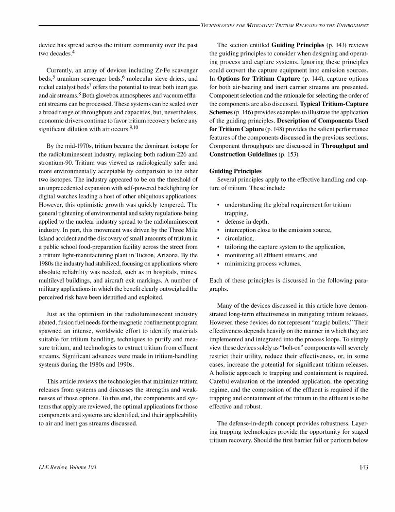
Figure 103.26Inert gas detritiation options depend on the target activity of the effluent and the intended application.
(c)In this document, tritiated water implies a mixture of H2O and HTO. In HTO, one proton has been replaced with a triton.
(d)Adsorption is a physical process by which water molecules bond to the surface of the molecular sieve without decomposing. During absorption, molecules decompose into their constituents and are incorporated into the bulk of the sorbing material.
(e)A drier containing 5 kg of molecular sieve will collect approximately 350 ml of water before any tritiated water is observed at the outlet of the drier.
(f)Regeneration is the process of removing adsorbed water by heating the molecular sieve and purging the drier with a very dry stream until the humidity of the purge gas at the drier exhaust drops below a target value, typically of the order of –80°C.
same oxidation system to ensure complete oxidation of tritiated hydrocarbon species. Additionally, the efficiency of oxidation decreases as the absolute concentration of hydrogen decreases. Hydrogen (protium) can be added in low concentrations to the effluent stream to raise the total hydrogen content in the stream and improve the oxidation efficiency.
In low-humidity applications and at low flow rates, the stream containing elemental tritium that has been oxidized

Technologies for MiTigaTing TriTiuM releases To The environMenT
LLE Review, Volume 103146
2. Inert Gas DetritiationThe options for detritiating inert gas streams are shown
in Fig. 103.26. These options rely on the ability of elemental tritium to bind chemically with preactivated metal powder. The tritium concentration leaving one of these hydride-forming materials depends on the metal. In general, uranium finds util-ity within circulating process loops where exhaust concentra-tions up to 10 mCi/m3 can be tolerated. Zr-Fe alloy, on the other hand, is more suited to polishing effluent streams and has the ability to reduce effluent concentrations below ~50 nCi/m3.
Streams containing less than a few tens of parts per million (ppm) water vapor and/or organic species can be processed directly via option 1 or 2 without the need to dry or precondi-tion the streams. Uranium will crack the incoming water vapor and modest quantities of hydrocarbons to form a uranium hydride/tritide, uranium oxides, and uranium carbides. The hydrogen can be released from the uranium metal thermally. However, the uranium oxide and carbides become irreversibly bound to the metal and represent a loss of hydrogen storage capacity and, ultimately, a reduction in the decontamination factor.(g) Water vapor will also react readily with the Zr-Fe alloy to form oxides. Hydrocarbons, however, tend to pass through the Zr-Fe alloy without reacting,8 unless gas residence times exceed 10 s.
As the impurity content increases above a few ppm in the effluent stream, the oxides are more likely to passivate the reactive metal, making it incapable of capturing elemental hydrogen. In such cases, a nickel catalyst can be introduced upstream of the uranium and/or Zr-Fe beds to crack the hydro-carbons and the water vapor to form nickel carbides and oxides, respectively.7 The hydrogen/tritium produced by the decompo-sition of the hydrocarbons or the water vapor passes through the nickel bed and is collected by the Zr-Fe alloy. Streams with larger water vapor loads, such as glovebox atmospheres, may require driers upstream of the nickel catalyst to remove the majority of the water first. In these applications, the nickel bed polishes the discharge from the drier to further decrease the stream humidity and reduces the load on the downstream hydrogen getter.
A cryogenic molecular sieve bed(h) can be added to the uranium/Zr-Fe circuit to facilitate in-situ regeneration of the
Zr-Fe alloy. The regeneration entails transferring the tritium inventory from the Zr-Fe alloy to the cryogenic molecular sieve bed in a closed-loop operation and subsequently releasing the gas from the molecular sieve bed as a slug to the uranium. The intermediate step of transferring to the cryogenic molecular sieve bed is required to increase the elemental tritium partial pressure so that the uranium can absorb the gas.
Finally, the selection of one technological approach to trap-ping over another requires a considered evaluation by the end user, taking into account economic factors, intended end goals, and application. Although trapping technology for air applica-tions tends to be somewhat more robust in that it is less likely to release its tritium inventory and less likely to be irreversibly damaged, that technology requires a significant investment in ancillary infrastructure if the tritium is to be reclaimed for re-use. Additional process loops are required to regenerate the drier and to collect and handle highly active water for either land disposal or for tritium recovery. In the latter case, the water must be decomposed in an electrolysis facility and the hydrogen transferred to an isotopic separation station for enrichment. On the other hand, metal beds are restricted to operate in inert gas streams. They can be destroyed with an unintentional ingress of air and release the entire resident tritium inventory during the accident. However, these metal beds capture elemental tritium directly and permit easy recovery of the gas for re-use. Metal beds avoid all issues related to water handling. Tritium enrichment, if required, can proceed directly after unloading the metal beds. In general, direct gas-capture systems are pre-ferred over oxidation approaches in applications that
• require the recovery and re-use of elemental gas or• lead to the production of high (>10 Ci/liter) specific activ-
ity water.
Direct gas-capture approaches can reduce gaseous emis-sions while simultaneously reducing the production of triti-ated solid wastes that must be land disposed. Direct inert gas-capturing approaches simplify tritium recycling because these approaches eliminate the need to convert tritiated water to elemental hydrogen.
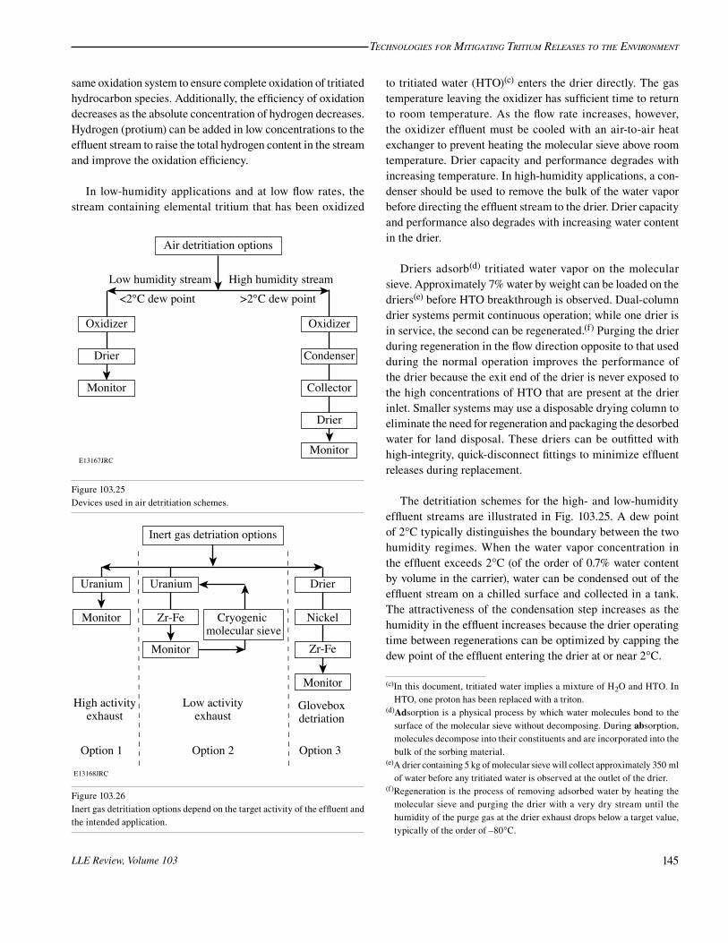
Typical Tritium-Capture SchemesA configuration commonly used to reduce emissions from
process loops is illustrated in Fig. 103.27. In this example, the tritium recovery subsystem comprising a tank, monitor, scavenger bed (or a train of scavenger beds if the makeup of the effluent dictates a more aggressive treatment), and isolation valves is installed between the process loop and the dry vacuum
(g)The decontamination factor is the ratio formed by dividing the inlet activity concentration by the outlet activity concentration.
(h)Elemental tritium can be adsorbed on a molecular sieve at 77 K (–196°C), provided all traces of water vapor are removed from the surface of the molecular sieve.
Technologies for MiTigaTing TriTiuM releases To The environMenT
LLE Review, Volume 103 147
pump.(i) Instead of evacuating the process loop directly to stack or via a single scavenger bed in a once-through operation, the contents of the process loop are expanded into the pre-evacuated tank for treatment. The process loop is then isolated from the tritium recovery system. Helium gas pressurizes the tritium recovery system to raise the system pressure to one atmosphere. The contents of the expansion tank are circulated through the scavenger bed and the progress of detritiating the stream is monitored with an inline tritium process monitor. At a prescribed concentration, the contents of the subsystem are then evacuated to the stack, or flushed from the subsystem with clean helium and the tank subsequently evacuated in preparation for the next operating cycle. Purging the lines with helium is recommended because the inert gas flush reduces the potential of residual tritium lingering in the plumbing between the tritium recovery system and the stack. An accumulation in this plumbing can unexpectedly trip alarms during subsequent operations and mask the actual cause of the emission.
E13169JRC
Processloop
Expansiontank
Helium
Monitor ScavengerCirculationpump
Monitor
Vacuumpump
Figure 103.27Incorporation of a simple cleanup subsystem into the exhaust of a process loop.
The second in-line tritium monitor between the vacuum pump and the treatment system is electronically coupled to the valve just upstream of the monitor. It automatically actuates the valve should the effluent activity exceed a predetermined level. Once the process loop has been isolated from the stack, an operator can intervene to rectify the fault, review the need
for continued processing and, when ready, release the treated effluent to the stack. In effect, this monitor buys the operator time to make an informed decision.
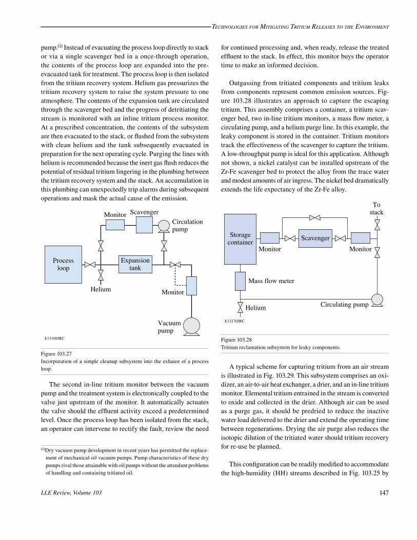
Outgassing from tritiated components and tritium leaks from components represent common emission sources. Fig- ure 103.28 illustrates an approach to capture the escaping tritium. This assembly comprises a container, a tritium scav-enger bed, two in-line tritium monitors, a mass flow meter, a circulating pump, and a helium purge line. In this example, the leaky component is stored in the container. Tritium monitors track the effectiveness of the scavenger to capture the tritium. A low-throughput pump is ideal for this application. Although not shown, a nickel catalyst can be installed upstream of the Zr-Fe scavenger bed to protect the alloy from the trace water and modest amounts of air ingress. The nickel bed dramatically extends the life expectancy of the Zr-Fe alloy.
E13170JRC
Storagecontainer
MonitorScavenger
Circulating pump
Monitor
Tostack
Mass flow meter
Helium
Figure 103.28Tritium reclamation subsystem for leaky components.
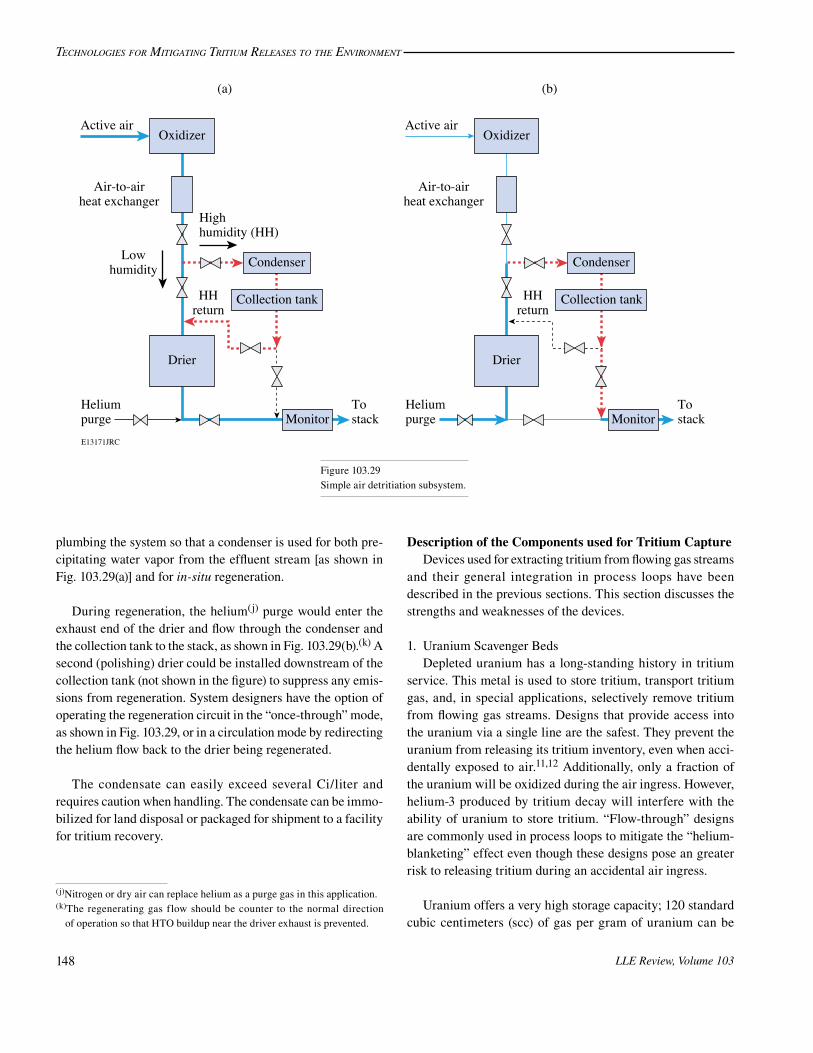
A typical scheme for capturing tritium from an air stream is illustrated in Fig. 103.29. This subsystem comprises an oxi-dizer, an air-to-air heat exchanger, a drier, and an in-line tritium monitor. Elemental tritium entrained in the stream is converted to oxide and collected in the drier. Although air can be used as a purge gas, it should be predried to reduce the inactive water load delivered to the drier and extend the operating time between regenerations. Drying the air purge also reduces the isotopic dilution of the tritiated water should tritium recovery for re-use be planned.
This configuration can be readily modified to accommodate the high-humidity (HH) streams described in Fig. 103.25 by
(i)Dry vacuum pump development in recent years has permitted the replace-ment of mechanical oil vacuum pumps. Pump characteristics of these dry pumps rival those attainable with oil pumps without the attendant problems of handling and containing tritiated oil.
Technologies for MiTigaTing TriTiuM releases To The environMenT
LLE Review, Volume 103148
plumbing the system so that a condenser is used for both pre-cipitating water vapor from the effluent stream [as shown in Fig. 103.29(a)] and for in-situ regeneration.
During regeneration, the helium(j) purge would enter the exhaust end of the drier and flow through the condenser and the collection tank to the stack, as shown in Fig. 103.29(b).(k) A second (polishing) drier could be installed downstream of the collection tank (not shown in the figure) to suppress any emis-sions from regeneration. System designers have the option of operating the regeneration circuit in the “once-through” mode, as shown in Fig. 103.29, or in a circulation mode by redirecting the helium flow back to the drier being regenerated.
The condensate can easily exceed several Ci/liter and requires caution when handling. The condensate can be immo-bilized for land disposal or packaged for shipment to a facility for tritium recovery.
Description of the Components used for Tritium CaptureDevices used for extracting tritium from flowing gas streams
and their general integration in process loops have been described in the previous sections. This section discusses the strengths and weaknesses of the devices.
1. Uranium Scavenger BedsDepleted uranium has a long-standing history in tritium
service. This metal is used to store tritium, transport tritium gas, and, in special applications, selectively remove tritium from flowing gas streams. Designs that provide access into the uranium via a single line are the safest. They prevent the uranium from releasing its tritium inventory, even when acci-dentally exposed to air.11,12 Additionally, only a fraction of the uranium will be oxidized during the air ingress. However, helium-3 produced by tritium decay will interfere with the ability of uranium to store tritium. “Flow-through” designs are commonly used in process loops to mitigate the “helium-blanketing” effect even though these designs pose an greater risk to releasing tritium during an accidental air ingress.
Uranium offers a very high storage capacity; 120 standard cubic centimeters (scc) of gas per gram of uranium can be
E13171JRC
Oxidizer
Air-to-airheat exchanger
Heliumpurge
Tostack
Active air
Condenser
Collection tank
Drier
HHreturn
Highhumidity (HH)
Lowhumidity
(a)
Monitor
Oxidizer
Air-to-airheat exchanger
Heliumpurge
Tostack
Active air
Condenser
Collection tank
Drier
HHreturn
(b)
Monitor
Figure 103.29Simple air detritiation subsystem.
(j)Nitrogen or dry air can replace helium as a purge gas in this application.(k)The regenerating gas flow should be counter to the normal direction
of operation so that HTO buildup near the driver exhaust is prevented.

Technologies for MiTigaTing TriTiuM releases To The environMenT
LLE Review, Volume 103 149
easily accommodated without compromising the reaction kinetics.13–15 It is well-suited to removing tritium from clean inert gas streams containing high tritium concentrations and offers uniform reaction kinetics over a very broad range of tritium-to-uranium (T/U) atom ratios.16 It is possible to charge uranium with tritium up to an atom ratio of nearly three tritium atoms per uranium atom although the operating range is usu-ally restricted to a ratio of 1.5 so that sufficient tritium storage capacity remains for unforeseen events.
Tritium gas reacts with the uranium to form a uranium tritide. This chemical compound is stable at room temperature. Heating the uranium tritide will release the tritium as a gas. The reaction is fully reversible. The pressure-composition isotherms for the uranium–tritium system are very simple.17 In the range of primary interest, i.e., at operating pressures below approximately 1.5 atm and at temperatures between 20°C and 450°C, the initiation of the tritide phase begins at T/U ~ 0.1 and is complete at T/U ~ 2.93. The plateau region between these two extremes is essentially flat. As a result, the temperature of the uranium tritide uniquely specifies the tritium gas pressure above the uranium powder. At 430°C, for example, the tritium gas pressure over uranium powder will be 1 atm. Caution is required when increasing the temperature much beyond 425°C; the pressure increases rapidly and can overpressurize the device containing the uranium. The equation
P 10 Torr.T4590 9 39=
- +^
_h
i (1)
prescribes the pressure over the temperature range of 150°C to 600°C. In this equation, the pressure (P) is in Torr and the temperature (T) is in Kelvin.
The reaction rate to form tritide is dramatically enhanced by preconditioning the uranium. The uranium metal is charged to capacity with hydrogen gas to form UH3 and subsequently unloaded by heating the UH3 to 425°C in a vacuum. The hydro-gen loading/unloading cycle should be repeated seven times to break down the uranium metal to its optimum size. This pro-cess, known as decrepitation, increases the surface area of the uranium by breaking down the bulk uranium metal into a fine powder with a particle distribution in the range of 0.1 to 10 nm. Following the last unloading, any residual hydrogen can be removed from the uranium by repeating the loading/unloading one additional time using isotopically downgraded tritium.
Uranium scavenger beds differ from storage devices in three ways. First, they require the carrier stream to flow through the container. Second, they operate at T/U ratios below 1 to
enhance the detritiation factor (DF). Third, they are typically constructed from larger diameter containers to reduce the car-rier molar flux(l) in the container. The equation18
. .logG 0 019 0 006DF T U1 2= -^ _h i (2)
relates the DF to the T/U for T/U ratios up to 2.5 and carrier molar fluxes (G) up to 2.5 mol/m2/s. This equation assumes an impurity-free carrier and a uranium operating temperature of 22°C.
Two conditions can deteriorate the performance of these devices. Impurities will coat the uranium powder surface and reduce the amount of uranium available for removing tritium from the carrier. Secondly, increasing the uranium temperature will increase the tritium partial pressure over the uranium and lower the DF.
Figure 103.30 illustrates the lowest tritium concentration attainable over uranium as a function of temperature. Inspec-tion of this figure is instructive for two reasons: it demon-strates how rapidly the DF will deteriorate with increasing temperature, and it illustrates that the lowest attainable tritium concentration in a carrier stream possible at room temperature with a uranium scavenger bed will be in the 10 mCi/m3 range.
(l)The molar flux of the carrier is the number of moles of carrier flow per unit time and per unit cross sectional area of container perpendicular to the flow direction. It is usually expressed as mol/m2/s.
Figure 103.30Tritium concentration dependence on uranium powder temperature.
E13172JRCTemperature (°C)
100
101
102
103
Triti
um c
once
ntra
tion
(mC
i/m3 )
10 20 50 8030 40 60 70
P = 10(–4469/T + 9.459)

Technologies for MiTigaTing TriTiuM releases To The environMenT
LLE Review, Volume 103150
Increasing the uranium temperature twofold, from 20°C to 40°C, decreases the DF tenfold. Operating a uranium scavenger bed at 25°C precludes reducing the tritium activity of a carrier below 10 mCi/m3.
Unconfined uranium powder oxidizes spontaneously when exposed to air. Undoubtedly, the term “pyrophors,” used in the radioluminescent industry when referring to uranium storage beds, reflects some historic incident related to the propensity of the powder to ignite. Confined uranium powder, however, has a limited reaction with air, particularly if the container uses a low-porosity stainless steel filter to prevent uranium powder from migrating out of the device. In general, these devices will lose approximately 30% of their storage capacity and will not release their tritium inventory during an air ingress accident. Uranium tritide is the most secure tritium storage vehicle avail-able to the tritium community, including any accident scenario involving air ingress not involving a flow-through configura-tion, i.e., a construction that permits air to enter via one port only and then becomes “dead-headed.”
Flow-through devices, both for storage and scavenging applications, are used to preclude helium blanketing. Blanket-ing occurs when decay-helium interferes with the bulk flow of tritium gas to the uranium powder. During blanketing, the rate of gas transfer from a vessel to the uranium powder stalls before all the tritium has had an opportunity to transform into a tritide. The balance of the tritium in the process system volume, however, can be captured on the uranium powder by circulat-ing the remaining gas over the powder to dislodge the helium cover. Any air ingress during circulation will completely and rapidly oxidize and nitride the uranium with a concomitant release of the entire resident tritium inventory to the carrier downstream of the device. Flow-through operations represent the single most likely action that can precipitate a significant tritium release. Extreme care must be exercised during flow-through operations. Housing the process equipment in an inert environment is a very effective way of preventing the accidental ingress of air during circulation.
2. Zr-Fe Scavenger BedsA Zr-Fe alloy developed by SAES Getters under the trade
name ST198 can also be used to scavenge tritium from gas streams.1 The alloy can be used in conjunction with noble gas carriers and nitrogen gas streams, albeit there is a gradual loss of capacity with time as the elements of the alloy nitride.5 As with uranium metal, the alloy spontaneously forms a tritide when exposed to elemental tritium; the reaction is reversible. The alloy must be heated to 550°C for the tritium recovery
and has a moderate storage capacity for tritium, typically of the order of 0.8 scc of gas per gram of alloy.
The nominal operating temperature for ST198 is 350°C. Decreasing the operating temperature increases the storage capacity for tritium gas. Decreasing the operating tempera-ture also decreases the tritium partial pressure over the alloy, thereby improving the DF. However, the reaction kinetics and the tolerance of the alloy to any impurities entrained in the carrier also decrease with decreasing temperature. Addition-ally, the modest ability of the alloy to crack organic volatile species decreases. Operating above 300°C strikes a reasonable balance between the various competing factors. At 350°C, excellent tritium scavenging properties are exhibited by ST198 in noble gas streams, provided the gas residence time in the reactor exceeds 3 s.
Scavenging tritium from a nitrogen environment requires special attention. The alloy exhibits good scavenging proper-ties in nitrogen at 350°C. The reaction kinetics between the alloy and nitrogen are slow at this temperature; however, the rate of nitriding increases noticeably at alloy temperatures above 400°C. The alloy is unusable at 500°C in the presence of nitrogen. Operating conditions that momentarily spike the alloy above 500°C can lead to a runaway nitriding condition. The alloy will react vigorously with the nitrogen cover gas to release approximately 600 kJ per mole of gas consumed. This energy will heat the alloy to very high temperatures and desorb the entire tritium inventory from the alloy. For example, a sudden ingress of 20-scc air into the nitrogen carrier stream could precipitate such a runaway condition unless the alloy temperature is monitored and the flow stopped whenever the alloy temperature exceeds 400°C in nitrogen. Nitriding ST198 is irreversible and will decrease the capacity of the bed.
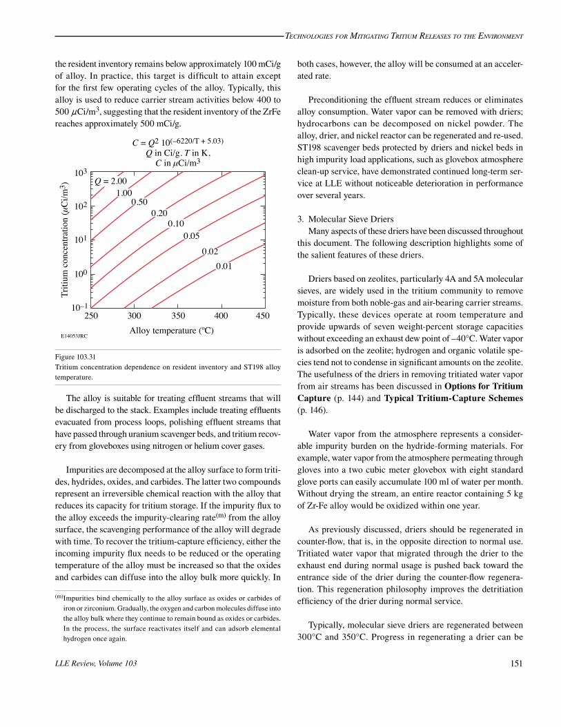
The pressure-composition isotherm for the Zr-Fe alloy/hydrogen system is considerably more complex than the ura-nium/hydrogen system. A single tritide phase does not exist for the Zr-Fe alloy/hydrogen system. The elemental gas pressure over the alloy depends on both the resident tritium inventory of the alloy and the operating alloy temperature. The relationship between tritium pressure P in Torr, the resident inventory Q in Torr-liters/g, and the alloy temperature T in Kelvin is given by the equation
* .P Q 10 .T2 6220 5 03=
- +_ i (3)
Inspection of Fig. 103.31 reveals that operating at 350°C will reduce the activity of a carrier below 20 nCi/m3, provided
Technologies for MiTigaTing TriTiuM releases To The environMenT
LLE Review, Volume 103 151
the resident inventory remains below approximately 100 mCi/g of alloy. In practice, this target is difficult to attain except for the first few operating cycles of the alloy. Typically, this alloy is used to reduce carrier stream activities below 400 to 500 nCi/m3, suggesting that the resident inventory of the ZrFe reaches approximately 500 mCi/g.
E14053JRC
25010–1
100
101
102
103
300 350 400 450Alloy temperature (ºC)
Triti
um c
once
ntra
tion
(mC
i/m3 )
C = Q2 10(–6220/T + 5.03)Q in Ci/g. T in K,
C in mCi/m3
0.010.02
0.050.10
0.200.50
1.00Q = 2.00
Figure 103.31Tritium concentration dependence on resident inventory and ST198 alloy temperature.
The alloy is suitable for treating effluent streams that will be discharged to the stack. Examples include treating effluents evacuated from process loops, polishing effluent streams that have passed through uranium scavenger beds, and tritium recov-ery from gloveboxes using nitrogen or helium cover gases.
Impurities are decomposed at the alloy surface to form triti-des, hydrides, oxides, and carbides. The latter two compounds represent an irreversible chemical reaction with the alloy that reduces its capacity for tritium storage. If the impurity flux to the alloy exceeds the impurity-clearing rate(m) from the alloy surface, the scavenging performance of the alloy will degrade with time. To recover the tritium-capture efficiency, either the incoming impurity flux needs to be reduced or the operating temperature of the alloy must be increased so that the oxides and carbides can diffuse into the alloy bulk more quickly. In
both cases, however, the alloy will be consumed at an acceler-ated rate.
Preconditioning the effluent stream reduces or eliminates alloy consumption. Water vapor can be removed with driers; hydrocarbons can be decomposed on nickel powder. The alloy, drier, and nickel reactor can be regenerated and re-used. ST198 scavenger beds protected by driers and nickel beds in high impurity load applications, such as glovebox atmosphere clean-up service, have demonstrated continued long-term ser-vice at LLE without noticeable deterioration in performance over several years.
3. Molecular Sieve DriersMany aspects of these driers have been discussed throughout
this document. The following description highlights some of the salient features of these driers.
Driers based on zeolites, particularly 4A and 5A molecular sieves, are widely used in the tritium community to remove moisture from both noble-gas and air-bearing carrier streams. Typically, these devices operate at room temperature and provide upwards of seven weight-percent storage capacities without exceeding an exhaust dew point of –40°C. Water vapor is adsorbed on the zeolite; hydrogen and organic volatile spe-cies tend not to condense in significant amounts on the zeolite. The usefulness of the driers in removing tritiated water vapor from air streams has been discussed in Options for Tritium Capture (p. 144) and Typical Tritium-Capture Schemes (p. 146).
Water vapor from the atmosphere represents a consider-able impurity burden on the hydride-forming materials. For example, water vapor from the atmosphere permeating through gloves into a two cubic meter glovebox with eight standard glove ports can easily accumulate 100 ml of water per month. Without drying the stream, an entire reactor containing 5 kg of Zr-Fe alloy would be oxidized within one year.
As previously discussed, driers should be regenerated in counter-flow, that is, in the opposite direction to normal use. Tritiated water vapor that migrated through the drier to the exhaust end during normal usage is pushed back toward the entrance side of the drier during the counter-flow regenera-tion. This regeneration philosophy improves the detritiation efficiency of the drier during normal service.
Typically, molecular sieve driers are regenerated between 300°C and 350°C. Progress in regenerating a drier can be
(m)Impurities bind chemically to the alloy surface as oxides or carbides of iron or zirconium. Gradually, the oxygen and carbon molecules diffuse into the alloy bulk where they continue to remain bound as oxides or carbides. In the process, the surface reactivates itself and can adsorb elemental hydrogen once again.

Technologies for MiTigaTing TriTiuM releases To The environMenT
LLE Review, Volume 103152
monitored by measuring the temperature of the purge gas leav-ing the drier. During the early phase of a regeneration cycle, the gas temperature leaving the drier will remain at, or close to, room temperature, even though the drier shell is fixed at 350°C. Most of the energy delivered to the molecular sieve by external band heaters clamped to the drier shell or by heated purge gas is used to desorb the water from the molecular sieve. Once the majority of the water has been released and purged from the drier, the temperature of the exhaust gas will gradually increase to the regeneration temperature. To thoroughly void the drier, the regeneration cycle should continue an additional 5000 volume exchanges of the drier, while the exhaust gas is at the regeneration temperature.
4. Cryogenic Molecular SieveThe earliest application of cryogenic molecular sieves(n) was
to separate hydrogen isotopes by gas–solid chromatography for the purpose of analyzing isotopic mixtures of elemental hydrogen.19 Since that time, a variety of isotopic separation systems have been developed to selectively recover tritium from the other hydrogen isotopes.20
As temporary storage devices, however, cryogenic molecu-lar sieves have found limited general utility in the tritium community. Nevertheless, these devices offer unique service in specialized applications, namely as short-term traps to capture tritium gas from a carrier and as tritium gas concentrators. For example, without the concentration step provided by the cryogenic molecular sieve, tritium could not be transferred to uranium from Zr-Fe except at high tritium partial pressures. At a concentration of 1 mCi/m3, elemental tritium will pass through the uranium powder without reacting. At 77 K, the molecular sieve can condense hydrogen on its surfaces to reduce the hydrogen partial pressures in the carrier into the 10–6 to 10–5 torr range and release the hydrogen at a partial pressure of several mTorr when heated to 150 K. As a con-sequence, tritium can be released from a Zr-Fe reactor at an activity of 1 mCi/m3, accumulated on a cryogenic molecular sieve, and released as a slug of gas at concentrations exceeding 1 Ci/m3 at 150 K.
Figure 103.32 illustrates the transfer of tritium gas from ST198 alloy to a cryogenic molecular sieve. Helium gas exits from hot ST198 alloy, flows through a cryogenic molecular sieve, and returns to the ST198 alloy. In this example, the car-rier activities at the ST198 exhaust and the cryogenic exhaust are monitored as a function of time. The activity at the ST198
(n)Cryogenic molecular sieves operate at 77 K.
exhaust varies with the temperature of the alloy and is seen to increase as high as 810 mCi/m3. The activity of the helium gas leaving the cryogenic molecular sieve remains below 50 nCi/m3, the sensitivity level of the in-line ionization chamber. At 88 min into the operation, tritium breaks through the molecular sieve and the activity of the gas leaving the cryogenic molecu-lar sieve increases rapidly, albeit in the low mCi/m3 range. The hydrogen content leaving the ST198 was not measured in this test. These tests demonstrate the excellent performance of the cryogenic molecular sieve trap to decontaminate the carrier stream, attaining DF’s up to (750/0.5) 1500 in a single pass. This figure of merit is conservative since the presence of hydrogen was not included in the estimate.
At 77 K, tritium gas is resident on the cryogenic molecu-lar sieve for a finite time and will slowly migrate toward the exhaust end of the bed. The transport rate from bed entrance to exhaust depends on the carrier flow rate, resident tritium inventory, resident hydrogen inventory, and the quantity of polar impurities adsorbed on the zeolite. Capacities of the order of 100 scc of elemental gas per gram of molecular sieve can be achieved on conditioned molecular sieve.
In a second example, a cryogenic molecular sieve can be used to capture the accidental release of elemental tritium from a process loop. In this case, the majority of the tritium may be held up on a cryogenic molecular sieve for 1 or 2 h before migrating through the bed. During this time, an operator can rectify the problem and return the gas directly to a storage bed.
E13174JRCTime (min)
0
200
400
600
800
1000
12060 800 20 40 1000
1
2
3
4
5
Ups
tream
act
ivity
(mC
i/m3 )
Dow
nstre
am a
ctiv
ity (m
Ci/m
3 )
Figure 103.32Comparison of tritium activities upstream and downstream of a cryogenic molecular sieve bed during the regeneration of a Zr-Fe bed. Helium carrier flow rate is 28 sLPM.

Technologies for MiTigaTing TriTiuM releases To The environMenT
LLE Review, Volume 103 153
Table 103.III: Size of the devices (in kilograms) used for three different detritiation applications.
Device Application
Effluent treatment system without air(a)
Glovebox cleanup system using helium(b)
Detritiation system for high-humidity air streams(b)
Oxidizer Not used Not used 1
Drier Not used 3 5
Nickel bed 1(c) 1.5 Not used
Uranium bed 1 Not used Not used
Zr-Fe bed 3 5 Not used(a)A volumetric flow rate below 10 sLPM is assumed,(b)A volumetric flow rate of 60 sLPM is assumed.(c)The quantity of material used in each device reflects the overall size of the capture devices.
Cryogenic molecular sieve beds can be regenerated in steps to release different tritiated species. By raising the molecular sieve temperature from 77 K to 150 K, the elemental tritium gas will be released. Increasing the temperature further to 350°C will release all other bound impurities. Elemental tritium can be directed to one treatment process while impurities can be directed to a second treatment process.
These devices have several limitations. They are restricted to operate in helium purge streams, and the residence time on the molecular sieve is limited. Cryogenic molecular sieve beds behave more like capacitors than storage devices. They are not passively safe in that liquid nitrogen is needed to hold the tritium gas in place. There is limited experience with these devices in the tritium community for the applications discussed. Despite these limitations, however, cryogenic molecular sieve beds will fill a unique application in tritium-handling systems in the coming years.
Throughput and Construction GuidelinesThe capture technology discussed in this article is intended
for small-scale operations, typically required to operate between 10 standard liters/min (sLPM) to 60 sLPM with a focus on treating the emission as close to the source as fea-sible. Flow rates in the 10-sLPM range are suitable to a variety of process loops. Flow rates in the 60-sLPM range are more suited to glovebox cleanup applications. Table 103.III lists the approximate size of each capture device for these two through-put extremes and for three applications.
All heated devices must be rated to withstand elevated pressures, that is, they must be rated as pressure fittings. These devices must be constructed in shops qualified to build pres-
sure vessels. The vessels must be helium leak-tight to 1 # 10–9 atm-cc/s when exposed to 1 atm of helium. The valves should be bellows-sealed and use a copper or stellite stem tip. Where valve actuation will be automated, VESPEL®(o) stem tips can be used, although these will require routine replacement. Stainless-steel frits should be integrated into device designs to prevent particulate transport into the process loop or the exhaust line.
Double containment can be used for devices that are expected to operate at an elevated temperature, such as uranium storage beds, where tritium permeation can be problematic. Doubly contained devices provide a secondary shell around the primary vessel. Heaters and thermocouples are attached to the primary vessel, and vacuum feed-throughs are used to access the heaters and thermocouples. The annular region between the primary and secondary vessels is evacuated and maintained under vacuum during operation. Periodically, the region is pumped to recover any tritium that has permeated into the interspace. Doubly contained devices release less tritium by permeation and consequently reduce the spread of surface contamination in the vicinity of the device. Addition-ally, these devices reduce heat loads in confined spaces such as gloveboxes. However, double-containment devices can easily cost twice that of single-containment device.
Uranium scavenger beds require manufacturing shops knowledgeable in handling and conditioning uranium. These facilities must be licensed to receive and handle bulk uranium metal. Manufacturing Zr-Fe and nickel beds requires caution to ensure the getter material is not accidentally oxidized during the manufacturing process.
(o)VESPEL® is a polyimide with good stability under radiation exposure.
Technologies for MiTigaTing TriTiuM releases To The environMenT
LLE Review, Volume 103154
ConclusionSignificant developments in tritium-capture technology for
both air and inert gas streams have occurred over the past two decades. Tritium removal from air streams requires the oxi-dation of elemental tritium and the collection of the tritiated water on driers; recovery from inert streams can also use the oxidation. Alternately, metal getter technology can be used to detritiate inert gas streams by collecting elemental tritium directly without the oxidation step.
Direct elemental tritium recovery offers several advantages. Elemental tritium is significantly less hazardous to handle than tritium oxide. In some cases, the elemental tritium can be returned to the original storage device for re-use. Oxidation technology tends to be more robust; however, unless special infrastructure is installed, oxidized tritium is a waste stream destined for land disposal. Each tritium-capture application should be carefully evaluated to assess the merits and draw-backs of oxidation against direct elemental recovery before selecting a capture technology.
Capture technology does not provide magical “bolt-on” solu-tions to process systems that suffer from chronic or repeated accidental releases. Rather, this technology must be integrated with the operation of the process systems. Both the process sys-tems and the capture technology need to be configured for reli-able, fail-safe operation. For example, circulating closed-loop capture subsystems are preferred to once-through subsystems. Process loop exhaust lines to the stack should be monitored for activity and interlocked with valves that automatically isolate the system from discharging tritium to the stack above predetermined limits.
Economics favors small-scale systems. Emissions should be treated as close to the source as possible, certainly before any significant dilution with air or inert gas occurs, as the first step in reducing the size of the capture equipment. Distributed capture subsystems are preferred to one large clean-up system attached to the stack; the former costs significantly less. Addi-tionally, releases in one process do not impact the operation of other processes.
ACKNOWLEDGMENTThis work was supported by the U.S. Department of Energy Office of
Inertial Confinement Fusion under Cooperative Agreement No. DE-FC52-92SF19460, the University of Rochester, and the New York State Energy Research and Development Authority. The support of DOE does not constitute an endorsement by DOE of the views expressed in this article.
REFERENCES
1. C. Boffito et al., J. Vac. Sci. Technol. 18, 1117 (1981).
2. C. Boffito, F. Doni, and L. Rosai, J. Less-Common Met. 104, 149 (1984).
3. P. Manini et al., Vuoto Sci. Tecnol. XX, 299 (1990).
4. W. T. Shmayda, N. P. Kherani, B. Wallace, and F. Mazza, Fusion Technol. 21, 616 (1992).
5. K. J. Maynard, N. P. Kherani, and W. T. Shmayda, Fusion Technol. 28, 1546 (1995).
6. W. T. Shmayda and N. P. Kherani, Fusion Eng. Des. 10, 359 (1989).
7. A. B. Antoniazzi and W. T. Shmayda, Fusion Technol. 30, 879 (1996).
8. W. T. Shmayda, in Safety in Tritium Handling Technology, edited by F. Mannone, Nuclear Science and Technology, Vol. 1 (Kluwer Aca-demic Publishers, Dordrecht, The Netherlands, 1993), pp. 23–52.
9. H. Brunnader, W. T. Shmayda, D. R. Harding, L. D. Lund, and R. Janezic, Fusion Sci. Technol. 41, 840 (2002).
10. A. Nobile, H. Reichert, R. T. Janezic, D. R. Harding, L. D. Lund, and W. T. Shmayda, Fusion Sci. Technol. 43, 522 (2003).
11. G. R. Longhurst, A. G. Heics, and W. T. Shmayda, Fusion Technol. 21, 1017 (1992).
12. G. R. Longhurst and W. T. Shmayda, Fusion Eng. 2, 812 (1989).
13. W. T. Shmayda and P. Mayer, J. Less-Common Met. 104, 239 (1984).
14. N. P. Kherani and W. T. Shmayda, in Proceedings of the Seventh Annual Conference (Canadian Nuclear Society, Toronto, Ontario, Canada, 1986), pp. 232–236.
15. N. P. Kherani, W. T. Shmayda, and A. G. Heics, Z. Phys. Chem. 164, 1421 (1988).
16. W. T. Shmayda, N. P. Kherani, and A. G. Heics, J. Vac. Sci. Technol. A 6, 1259 (1988).
17. W. M. Mueller, J. P. Blackledge, and G. G. Libowitz, Metal Hydrides (Academic Press, New York, 1968).
18. W. T. Shmayda and N. P. Kherani, Fusion Eng. Des. 10, 359 (1989).
19. P. L. Gant and K. Yang, Science 129, 1548 (1959).
20. C. H. Cheh, J. Chromatography A 658, 283 (1994).