technische universität münchen universität münchen ... of collecting and governing sensor data...
TRANSCRIPT

Technische Universität MünchenDepartment of Informatics
Bachelor’s Thesis in Informatics
A multi-tenant and privacy-preservinginformation processing system
Thomas Mauerer


Technische Universität MünchenDepartment of Informatics
Bachelor’s Thesis in Informatics
A multi-tenant and privacy-preserving information processingsystem
Ein mandantenfähiges und Privatheit achtendesInformationsverarbeitungssystem
Author Thomas MauererSupervisor Prof. Dr.-Ing. Georg CarleAdvisor Marcel von Maltitz, M.Sc., Dr. Holger Kinkelin, Dipl.-Inf. Johann SchlampDate January 15, 2016
Informatik VIIIChair for Network Architectures and Services


I con�rm that this thesis is my own work and I have documented all sources and materialused.
Garching b. München, January 15, 2016
Signature


Abstract
In today’s world smartphones have become indispensable. Most people use smartphonesfor sur�ng, chatting, email, photos, playing games, etc. However, another possibleapplication is to use the available sensors (hardware and software) in order to measureseveral aspects. Collected data can be used for research studies or to compile statistics,for instance. For the process of collecting and governing sensor data of Android devicesthe MeasrDroid framework can be used. However, it is currently not possible to usethe capabilities of MeasrDroid for individual situations, but only to support research bydonating data.
This thesis is part of a bigger project which has the main goal to introduce multi-tenancy in MeasrDroid in a privacy-preserving way. Therefore, the overall structureand architecture of MeasrDroid has changed. Virtual machines are introduced as theindividual data sink for each tenant which can be used in order to store collected datacon�dentially.
Apart from encryption, privacy preservation requires also an authenticated and integrity-checked connection for every data transmission. Therefore, the MeasrDroid PairingProtocol has been introduced which enables the establishment of such a connection.This can either be achieved by the use of self-signed certi�cates or by the use of a PKI.The protocol needs to be performed before data is sent from one entity to another oneand can therefore be seen as the initial pairing. Because of the protocol clients can alsobe allowed to directly push data to the VM where it is stored. This enables real-timedata collection which has not been possible in the existing MeasrDroid project.
Apart from providing the theory to the MeasrDroid Pairing Protocol and the new archi-tecture in general, this thesis includes also the implementation of the aforementionedprotocol for the pairing between clients and VMs. Security plays a major role in thewhole project because security is closely related with privacy which is the essentialrequirement. Therefore, the security model is investigated in detail in order to provethat privacy is obtained as best as possible.


I
Contents
1 Introduction 11.1 Motivation . . . . . . . . . . . . . . . . . . . . . . . . . . . . . . . . . . 11.2 Problem . . . . . . . . . . . . . . . . . . . . . . . . . . . . . . . . . . . 21.3 Goals and Research Questions . . . . . . . . . . . . . . . . . . . . . . . 21.4 Structure of this Document . . . . . . . . . . . . . . . . . . . . . . . . . 3
2 Background 52.1 De�nition: Privacy Preservation . . . . . . . . . . . . . . . . . . . . . . 52.2 MeasrDroid Project . . . . . . . . . . . . . . . . . . . . . . . . . . . . . 6
2.2.1 MeasrDroid Core . . . . . . . . . . . . . . . . . . . . . . . . . . 62.2.2 Backend Infrastructure . . . . . . . . . . . . . . . . . . . . . . . 62.2.3 Necessity of Changes . . . . . . . . . . . . . . . . . . . . . . . . 7
2.3 Cryptography . . . . . . . . . . . . . . . . . . . . . . . . . . . . . . . . 82.3.1 Public-Key Encryption . . . . . . . . . . . . . . . . . . . . . . . 82.3.2 Message Authentication Code . . . . . . . . . . . . . . . . . . . 92.3.3 Public Key Infrastructure . . . . . . . . . . . . . . . . . . . . . . 112.3.4 SSL/TLS . . . . . . . . . . . . . . . . . . . . . . . . . . . . . . . 13
3 Analysis 153.1 Structure and Privacy Model . . . . . . . . . . . . . . . . . . . . . . . . 153.2 Overall Architecture . . . . . . . . . . . . . . . . . . . . . . . . . . . . . 16
3.2.1 Individual Data Sinks . . . . . . . . . . . . . . . . . . . . . . . . 163.2.2 Statistical Database . . . . . . . . . . . . . . . . . . . . . . . . . 173.2.3 Trusted Tenant Device . . . . . . . . . . . . . . . . . . . . . . . 183.2.4 Virtual Machine Management . . . . . . . . . . . . . . . . . . . 18
3.3 Use Cases . . . . . . . . . . . . . . . . . . . . . . . . . . . . . . . . . . . 183.3.1 Measurement of a Private Area . . . . . . . . . . . . . . . . . . 183.3.2 Support Research . . . . . . . . . . . . . . . . . . . . . . . . . . 193.3.3 Comparison of Measurements . . . . . . . . . . . . . . . . . . . 19
3.4 Attacker Model . . . . . . . . . . . . . . . . . . . . . . . . . . . . . . . 193.5 MeasrDroid Pairing Protocol . . . . . . . . . . . . . . . . . . . . . . . . 20

II Contents
4 Design 234.1 Pairing based on Self-Signed Certi�cates . . . . . . . . . . . . . . . . . 23
4.1.1 Client↔ VM . . . . . . . . . . . . . . . . . . . . . . . . . . . . 234.1.2 VM↔ VM . . . . . . . . . . . . . . . . . . . . . . . . . . . . . . 24
4.2 Pairing based on a PKI . . . . . . . . . . . . . . . . . . . . . . . . . . . 274.2.1 Client↔ VM . . . . . . . . . . . . . . . . . . . . . . . . . . . . 274.2.2 VM↔ VM . . . . . . . . . . . . . . . . . . . . . . . . . . . . . . 30
5 Implementation 335.1 MeasrDroid Core . . . . . . . . . . . . . . . . . . . . . . . . . . . . . . 33
5.1.1 QR-Code Scanner . . . . . . . . . . . . . . . . . . . . . . . . . . 335.1.2 Certi�cate Tools . . . . . . . . . . . . . . . . . . . . . . . . . . 355.1.3 HTTP Client . . . . . . . . . . . . . . . . . . . . . . . . . . . . 365.1.4 Pairing Manager . . . . . . . . . . . . . . . . . . . . . . . . . . 375.1.5 Pairing Service . . . . . . . . . . . . . . . . . . . . . . . . . . . 385.1.6 Graphical User Interface . . . . . . . . . . . . . . . . . . . . . . 38
5.2 MeasrDroid Backend . . . . . . . . . . . . . . . . . . . . . . . . . . . . 385.2.1 TLS Protection . . . . . . . . . . . . . . . . . . . . . . . . . . . 405.2.2 Pairing and User Feedback . . . . . . . . . . . . . . . . . . . . . 40
6 Evaluation 416.1 Usability . . . . . . . . . . . . . . . . . . . . . . . . . . . . . . . . . . . 416.2 Performance . . . . . . . . . . . . . . . . . . . . . . . . . . . . . . . . . 416.3 Privacy Preservation . . . . . . . . . . . . . . . . . . . . . . . . . . . . 426.4 Evaluation of the Two Solutions . . . . . . . . . . . . . . . . . . . . . . 43
6.4.1 Investigation of the Security Model (Self-Signed) . . . . . . . . 446.4.2 Investigation of the Security Model (PKI) . . . . . . . . . . . . . 446.4.3 General Comparison . . . . . . . . . . . . . . . . . . . . . . . . 45
6.5 Real-Time Data Collection . . . . . . . . . . . . . . . . . . . . . . . . . 46
7 Related Work 49
8 Conclusion and Outlook 51
Appendices 53
Appendix A Abbreviations 55
Appendix B Glossary 57
Bibliography 59

III
List of Figures
1.1 Number of Smartphone Users [1] . . . . . . . . . . . . . . . . . . . . . 2
2.1 Overview of the Backend Components . . . . . . . . . . . . . . . . . . 72.2 Hierarchical PKI . . . . . . . . . . . . . . . . . . . . . . . . . . . . . . . 12
3.1 Structure of MeasrDroid . . . . . . . . . . . . . . . . . . . . . . . . . . 163.2 Overall Architecture . . . . . . . . . . . . . . . . . . . . . . . . . . . . . 17
4.1 Pairing between a Client and a VM based on Self-Signed Certi�cates . 254.2 Pairing between two VMs based on Self-Signed Certi�cates . . . . . . . 264.3 Pairing between a Client and a VM based on a PKI . . . . . . . . . . . . 294.4 Pairing between two VMs based on a PKI . . . . . . . . . . . . . . . . . 30
5.1 Graphical User Interface . . . . . . . . . . . . . . . . . . . . . . . . . . 39

IV List of Figures

V
List of Tables
2.1 Format of X.509 . . . . . . . . . . . . . . . . . . . . . . . . . . . . . . . 11

VI List of Tables

1
Chapter 1
Introduction
1.1 Motivation
Smartphones are omnipresent all over the world. Figure 1.1 shows a prediction of thenumber of people using a smartphone. At the time of this writing 7.32 billion peopleare living in the world [2]. This means that approximately 26 percent of all peoplein the world own a smartphone. According to �gure 1.1 the number of smartphoneusers is continually increasing on a linear basis. This may have two main reasons:Firstly, because the number of all people living in the world is increasing, too. Secondly,because smartphones have a vast amount of capabilities and can be useful in a hugevariety of situations. A smartphone is not just a device for telephony or text messaging[3]. However, it is more like a lightweight version of a desktop computer that canbe taken everywhere and has become more and more powerful over time. Hence,developing applications for smartphones is a good idea in general because many peopleare addressed this way.
Depending on the age and the manufacturer, smartphones are usually equipped witha multitude of hardware sensors. This includes sensors for motion, acceleration orenvironmental properties, like temperature or pressure. These data sources can becomplimented with software-based sensors, e.g. based on the wireless modules in orderto measure network characteristics like roundtrip times or signal strength. Gathereddata can then be exported in order to conduct research, compile statistics or to be usedotherwise.
For the process of collecting and governing sensor data the MeasrDroid framework wasdeveloped at the chair of Network Architectures and Services which is explained in detailin section 2.2.

2 Chapter 1. Introduction
Figure 1.1: Number of Smartphone Users [1]
1.2 Problem
As explained in section 2.2 the main goal of MeasrDroid is to conduct network research.Users can therefore participate in the project by donating data. However, the individualuser can not really take advantage of this because he has no access to the databasewhere all measurements are stored. By implication, this means that individual userscan currently not use the capabilities of MeasrDroid for their personal situations.
A second problem is that currently no real-time data collection is possible. This isdue to the security model which hinders clients to directly push data to the serverwhere it is stored. However, this reduces the application possibilities of MeasrDroidtremendously. One could think of using MeasrDroid as a communication infrastructurefor a feedback system, for instance. In this case it may be problematic if feedback is notgiven instantaneously.
1.3 Goals and Research Questions
The main goal is to redesign MeasrDroid in order to o�er the capabilities for individualsituations. Therefore, multi-tenancy must be introduced in a privacy-preserving way.This basically means that the system is able to deal with individual tenants in the waythat each tenant is the only party that has access to the measurements taken.

1.4. Structure of this Document 3
To obtain this goal the overall structure and architecture of MeasrDroid has changedwhich is explained in detail in chapter 3. The main innovation are individual data sinksfor every tenant in the form of virtual machines with no third-party access. There aretwo situations where data is sent from one entity of MeasrDroid to another one: Firstly,when a smartphone uploads gathered data to the virtual machine. Secondly, when atenant wants to share data with another tenant and therefore data is sent from one virtualmachine to another one. Beside from having no third-party access to measured data,privacy preservation also requires an authenticated and integrity-checked connectionin these two situations. For the establishment of such a connection a protocol has beenintroduced which manages the initial pairing between the two entities. This protocol isthe main part of this thesis.
In the same context the security model is investigated. This is necessary becausethe current security model has changed due to the new structure and architecture ofMeasrDroid (see chapter 3).
As a summary the research questions that will be answered in this thesis are as follows:
• RQ1: How can smartphones and virtual machines be paired to enable an authen-ticated and integrity-checked connection for uploading data?
• RQ2: How can two virtual machines be paired to enable an authenticated andintegrity-checked connection for sharing data?
• RQ3: How can real-time data collection be enabled without undermining thecommon security concept?
This thesis also includes the implementation of the aforementioned pairing protocol inMeasrDroid.
1.4 Structure of this Document
Chapter 2 describes fundamentals that are needed in order to understand the main theorypart of this thesis. As even being part of the title, privacy preservation is an importantrequirement. Therefore, chapter 2 starts with a de�nition of privacy preservation. Also,the MeasrDroid project is described as it is at the moment and aspects of cryptographyare explained.
Chapter 3 introduces the theory part of this thesis. It starts with the description of thenew structure of MeasrDroid and architecture. Afterwards the use cases are explainedand the attacker model is de�ned which leads to the central aspect of this thesis: theMeasrDroid Pairing Protocol.
Chapter 4 describes two possible solutions of the aforementioned MeasrDroid PairingProtocol. The �rst solution is based on self-signed certi�cates, whereas the second

4 Chapter 1. Introduction
solution uses a Public Key Infrastructure to achieve the same goals.
In chapter 5 the practical part of this thesis is documented. This is the implementationof the MeasrDroid Pairing Protocol.
Chapter 6 evaluates both the theoretical and practical part of this thesis under certainaspects. This chapter refers to the research questions and states how they are achieved.Also, a comparison of the two solutions described in chapter 4 is given here.
Chapters 7 and 8 �nally introduce to related work, conclude this thesis and providean outlook on further work that has to be done in order to have a privacy-preservingmulti-tenant MeasrDroid.

5
Chapter 2
Background
This chapter provides the reader with some basics and background knowledge neededto follow the discussions in chapters 3 and 4. A larger part of this section are aspects ofcryptography.
2.1 De�nition: Privacy Preservation
According to [4] privacy is a term for which no consistent de�nitions exist. Prof. Dr.Lutz Prechelt tries to de�ne it as the area in which a person can decide to whom, whenand why information is accessible [4]. This can be justi�ed by the so called GoldenRule (ethic of reciprocity) which prescribes to always treat others in the way one wouldalso expect others to treat oneself [4]. As a general rule, this means that every kindof information related to a person has to be kept private until the particular persondecides to share this information with others. In this thesis information basically meanscollected sensor data.
Privacy preservation then means methods to obtain privacy which can be achieved bymainly two possibilities: [4]
1. Physical Blockade: By taking appropriate measures of security it is not possiblefor an unauthorized person to get access to stored data. Furthermore, PhysicalBlockade means secrecy of sensitive data which is a crucial aspect of many securityconcepts.
2. Encryption: Data is never sent or stored in plain format but always encryptedand can only be decrypted by the authorized person.
This de�nition is subject of the overall new concept of MeasrDroid. Derived from thetwo aspects, privacy preservation requires also the authentication of communication

6 Chapter 2. Background
partners and veri�cation of the integrity of transmitted messages. This con�rms thatmessages are sent only to valid entities and are not manipulated during the transport.
2.2 MeasrDroid Project
This section describes the existing MeasrDroid project as it is at the moment and alsostates why changes are necessary in order to ful�l the research questions mentioned in1.3.
MeasrDroid is an Android framework for collecting and governing sensor data of An-droid devices [5]. The project was started in March 2011 by members of the chair ofNetwork Architectures and Services and more than 10 students [6]. The lead developeris Dipl.-Inf. Johann Schlamp who is also advisor of this thesis. The main goal is to runnetwork research [6]. MeasrDroid consists of a client (see 2.2.1) which is installed onthe device in order to measure sensor data and a backend infrastructure for storingcollected data (see 2.2.2).
2.2.1 MeasrDroid Core
The MeasrDroid Core is an Android application that has to be installed on the device.It is responsible for measuring sensor data. Collected data is always encrypted on thedevice before it is pushed to the backend server. At the �rst start a wizard opens whichlets the user con�gure several aspects, like how much data he wants to donate per dayor which sensors should be activated or deactivated [6]. The core itself does not consistof any activities. However, every Android application that wants to use the features ofMeasrDroid only has to include the core into the project, let the main class inherit fromthe core and mark it with the special @MeasrDroidSetup tag. The most famous Androidapplication that uses MeasrDroid is the MeasrDroid Application which is available onthe Google Play Store for free. [7] It lets the user visualize all taken measurements.
2.2.2 Backend Infrastructure
The aim of the MeasrDroid backend is to store collected data. The data can be madeavailable for research projects later on. An overview of the backend components isgiven in �gure 2.1.
The MeasrDroid backend consists of the following components:
• C3PO: The C3PO is the main server of MeasrDroid. It is responsible for decryptingcollected data and storing it in the database. The C3PO itself is not connected to

2.2. MeasrDroid Project 7
Figure 2.1: Overview of the Backend Components
the internet, due to security reasons. Therefore, it is not possible to directly pushdata to the C3PO.
• Upload.droid: The Upload.droid is the server where clients push their measureddata to. The Upload.droid is therefore accessible on the Internet. The C3POperiodically pulls the temporary stored data from the Upload.droid and stores itin the database.
• Database: All taken measurements are stored in a centralized database which isonly accessible by the C3PO.
2.2.3 Necessity of Changes
In general there are two aspects in the backend infrastructure which make it impossibleto ful�l the research questions (see 1.3) and general goals of this thesis without anychanges:
1. Centralized database: A single database for all taken measurements is notcompatible with a privacy-preserving multi-tenancy concept. That is because theoperator of MeasrDroid can learn all data collected from all clients and tenants,respectively. Instead, this should only be possible for the particular tenant.
2. Polling: Storing collected data in the database is currently not event-based, butdone by polling. This means that the C3PO periodically asks the Upload.droid

8 Chapter 2. Background
whether data is available. If this is the case, data gets pulled by the C3PO andis stored in the database. However, the time steps between two polls can not bemade arbitrary small because of two main reasons: Firstly, due to the amount ofprocessed data, depending on how many Android devices participate. Secondly,due to performance reasons. In general, it is not recommended to set the timestep as small as possible because this means that work is often in vain when nodata is available. However, this makes real-time data collection impossible.
2.3 Cryptography
This section describes basics of cryptography and protocols that are used in the Measr-Droid Pairing Protocol described in section 3.5.
2.3.1 Public-Key Encryption
Public-key encryption was invented in the mid-70s by M. Hellman, W. Di�e and R.Merkle. The idea behind public-key encryption is that every participant has a key pairconsisting of a public key KE and a private key KD . The public key can be made publiclyavailable, for example on a website, whereas the private key always has to be keptprivate. Data is then encrypted with somebody’s public key and can only be decryptedwith the dedicated private key. The advantage of public-key encryption is that there isno need for a shared secret between sender and receiver. The most famous public-keyencryption scheme is RSA [8] invented by R. Rivest, A. Shamir and L. Adleman. [9]
The most important properties of a public-key cryptosystem are as follows (a detailedde�nition can be found in [9]):
1. (KE ,KD ) can be created e�ciently and there is a relation between KE and KD .
2. ∀m ∈ M : D (E (m,KE ),KD ) = m, where M is the set of all plaintexts, E is theencryption function and D is the decryption function.
The security in public-key encryption lies in the fact that there is a relation f betweenthe public key KE and the private key KD but the private key can not be calculatede�ciently by just knowing the dedicated public key. That is because f is a so called oneway function: [9]
f : X −→ Y
1. ∀x ∈ X : f (x ) can be calculated e�ciently.
2. x = f −1 (y) can not be calculated e�ciently.
In general, it is not proven that one way functions exist at all [9]. However, one assumesthat every function is suitable if no e�cient algorithms are known to revert the function.

2.3. Cryptography 9
An example is the multiplication of two big primes p and q, so that n = p × q. This isquite easy to achieve. However, to revert this, one would have to solve the mathematicalproblem of factorizing a numbern in its primesp andq, for which no e�cient algorithmsare known if n is big enough. This is used in RSA, for instance. [9]
Encryption and decryption is also based on a one way function. However, this wouldmean that even an authorized person is not able to decrypt a message e�ciently. There-fore, a special form of a one way function is applied in this context, a so called trapdoorone way function. The de�nition is nearly the same, only aspect 2. changes to thefollowing: [9]
2. x = f −1 (y) can only be calculated e�ciently with the knowledge of an additionalinformation.
The additional information is the trapdoor which is the private key [9].
2.3.2 Message Authentication Code
A cryptographic hash function H is a non-injective function that maps every wordx ∈ X of arbitrary size to a value H (x ) ∈ Y of a �xed size k
H : X ∗ −→ Y k
and also has the following properties: [9]
1. H is a one way function:
• ∀x ∈ X : H (x ) can be calculated e�ciently.
• x = H−1 (y) can not be calculated e�ciently.
2. Given x ∈ X and the dedicated hash value h = H (x ). It is not e�ciently possibleto �nd x ′ ∈ X with x , x ′ that produces the same hash value, H (x ) = H (x ′) = h.
These two properties de�ne a cryptographic hash function with weak collision re-sistance. For a cryptographic hash function with strong collision resistance also thefollowing property must be ful�lled: [9]
3. It is not e�ciently possible to �nd two di�erent words x ,x ′ ∈ X that produce thesame hash value, H (x ) = H (x ′).
Cryptographic hash functions can be used to verify the integrity of a message m, forinstance. The calculated hash value h = H (m) is a �ngerprint form. Any transmissionerrors can be uncovered by re-calculating the hash value of the received message m′.If the re-calculated hash value h′ = H (m′) does not equal h, there were changes tom during the transmission. That is because any change to m leads to a completelydi�erent hash value due to the aforementioned properties. However, one can not use
10 Chapter 2. Background
cryptographic hash functions to protect against deliberate manipulation. That is becausean attacker can also re-calculate the hash value for the manipulated messageh′ = H (m′)
and replace the original h by h′.
The most famous and widely used cryptographic hash functions are the SHA-#-functions(where # means 1,2 or 3) [10] and the MD5 [11]. These are so-called dedicated hashfunctions [9].
Sometimes it is also necessary to authenticate the sender of a message beside fromhaving an integrity-protection. This is where MACs come into play: A MAC is acryptographic hash function combined with a secret key K only known to the senderand receiver of a message. A usual communication between Alice and Bob looks asfollows: [9]
1. Alice calculates a MAC for a messagem with the key K .
MAC (m,K ) =mac
2. Alice sends both, the messagem and the valuemac to Bob.
3. Bob veri�es the integrity of the received messagem∗ by calculating the MAC ofm∗ and comparing it with the received valuemac .
MAC (m∗,K ) =mac∗?=mac = MAC (m,K )
Usually the key K is concatenated to the messagem, som′ =m‖K orm′ = K ‖m. Thismeans that calculating the MAC of a message m is nothing more than performing acryptographic hash function H onm′:
MAC (m,K ) = H (m′)
Depending on the taken hash function, this can be problematic in the way that anattacker can modify the messagem and also calculate a valid MAC without even knowingthe secret key. He just has to concatenate his message m′′ with m′ and perform thecryptographic hash function. To prevent this attack one should always use the HMACprocedure in order to create a MAC. [9]
HMAC is a procedure that uses the hash function H two times. The key K is not onlyconcatenated with the message m but also with the result of the �rst run of the hashfunction:
HMAC (m,K ) = H (K ‖ (H (K ‖m)))
Using a hash function two times, increases collision resistance signi�cantly, too. Untiltoday, the HMAC procedure is considered to be secure. [9]

2.3. Cryptography 11
2.3.3 Public Key Infrastructure
As described in section 2.3.1 in public-key cryptography every participant has a key pairconsisting of a public and a private key. Without any further means several problemsmay occur: [12]
1. Authenticity of public keys: If Alice wants to send an encrypted message toBob, she takes Bob’s public key for encryption. However, when Bob’s public keyis spread on the Internet, Alice can not be sure that the key really belongs toBob. An attacker may have replaced Bob’s key with his own key without beingrecognized by Alice.
2. Revocation of public keys: If Bobs’s private key got lost or stolen, it is notsecure anymore to use this key pair for encryption. The key pair should thereforebe revoked and replaced by a new key pair. However, there are no ways for Aliceto recognize that Bob’s public key is not valid anymore.
3. Non-repudiation: If Alice signs a message with her private key, it should notbe possible to deny this signature. However, this is quite easy to achieve by justsaying that Alice’s public key does not belong to her.
The solution for the mentioned problems are digital certi�cates. A certi�cate is a signedpiece of data that maps somebody’s identity to the public key [12]. The common formatfor certi�cates is the X.509 format described in table 2.1.
Field ExplanationVersion The version �eld describes the version number of X.509. The
common version is 3.Serial Number The serial number is a unique id for a signing party to unambigu-
ously recognize the signed certi�cate.Signature The signature �eld describes the algorithm and additional param-
eters used for signing the certi�cate.Issuer The issuer is the name of the signing party. This has to be a X.500
conformable name.Validity The validity �eld describes the start and end date for the certi�-
cate to be valid.Subject The subject is the name of the owner of the certi�cate. This has
to be a X.500 conformable name.Public Key This is the public key that belongs to the owner of the certi�cate.
Table 2.1: Format of X.509
A certi�cate can either be self-signed or signed by an independent, so called Certi�cateAuthority (CA). Self-signed means that the subject is equal to the issuer.

12 Chapter 2. Background
In a common scenario there are multiple CAs and they are ordered hierarchically. Thismeans that there is one root CA who has a self-signed certi�cate which signs certi�catesfor underlying CAs. Those CAs may sign certi�cates for other participants in turn, forexample for Alice and Bob or other CAs. This ends up in a certi�cate chain. The ideabehind this is: if one trusts the root CA, one can also trust everybody else in the chain.The entirety of all participating parties is called a PKI. [12] An example PKI is illustratedin �gure 2.2.
Figure 2.2: Hierarchical PKI
The example shown in �gure 2.2 looks as follows: If Alice wants to send an encryptedmessage to Bob, she �rst veri�es Bob’s certi�cate. Bob’s certi�cate is signed by CA-Bwhich is in turn signed by CA-Root. Due to the fact that Alice trusts CA-Root, she canbe sure that Bob’s public key really belongs to Bob.
The solution for problem 2 is a Certi�cate Revocation List (CRL). This is simply a listprovided by a CA which contains all serial numbers of revoked certi�cates. If a certi�cateis part of this list, it should not be trusted anymore. [12]
The creation of a certi�cate is usually split into two parts. At �rst, a so called Certi�cateSigning Request (CSR) is created. This contains the subject and the public key. The CSRis then sent to the signing party (e.g. CA) which creates the actual certi�cate and signsit in the second step.

2.3. Cryptography 13
2.3.4 SSL/TLS
SSL (Secure Sockets Layer) and TLS (Transport Layer Security) are protocols locatedabove the transport layer in the OSI model [9]. All aforementioned aspects of cryptog-raphy, like Public-Key Encryption, Message Authentication Codes and Digital Certi�catesare part of these protocols. SSL was invented by Netscape with the goal of secure HTTPconnections. This is called HTTPS and means simply a secure SSL channel which canbe used to transfer HTTP data [9]. However, SSL can not only be used for HTTP but ahuge variety of protocols. An overview of these protocols can be found in [9]. TLS isthe improvement of SSL and is currently the international industry standard. However,the core aspects of TLS and SSL are the same [9].
The tasks of SSL/TLS can basically be divided into three parts: [9]
1. Authentication of Communication Partner: This is achieved by the use ofpublic-key encryption and digital certi�cates. The idea behind this is that a sendercan be sure that he is connected to the desired receiver.
2. Con�dential end-to-end transmission: This is achieved by the use of encryp-tion using a session key that is only known to the sender and the receiver.
3. Veri�cation of Integrity: This is achieved by the use of Message AuthenticationCodes. TLS supports only HMAC which is considered to be secure.
It is not prede�ned what algorithms of public-key encryption, symmetric encryptionor MACs should be used. This is negotiated in every connection. The procedure ofexchanging all necessary information and key material is not a trivial task. Hence, thisis not further explained in this thesis but can be found in detail in [9].
The security of SSL/TLS lies mainly in the used algorithms for cryptography. If onlysecure algorithms are used with recommended key lengths, the protocol is consideredto be secure. [9]
However, one known security leak is the management of digital certi�cates. If anattacker manages to get a valid certi�cate signed by a globally veri�able, trusted CA,he can redirect a client to a malicious server which authenticates itself with the validcerti�cate. In this case a client can not recognize that he is not connected to the desiredserver but to the malicious one. [9]

14 Chapter 2. Background

15
Chapter 3
Analysis
This chapter is the main theory part of this thesis. The reader gets information aboutthe new structure, as well as an overview of the new architecture of MeasrDroid. Also,the privacy model is de�ned in this chapter. This basically means at which layer we aregoing to obtain privacy preservation. The thoughts on this are required, due to the newstructure. Apart from that, use cases and the attacker model are presented which leadto the central aspect of this thesis: the MeasrDroid Pairing Protocol.
3.1 Structure and Privacy Model
A multi-tenancy concept requires a new structuring of MeasrDroid. Prior, every personthat participated in the project was an individual user of MeasrDroid per de�nition.Therefore, it was only necessary to install the application on the client device (smart-phone) and start donating data. This changes in the new concept. Figure 3.1 shows thenew structure of MeasrDroid.
According to �gure 3.1 a completely new layer is introduced: the layer of tenants. Perde�nition, every tenant is an individual user of MeasrDroid now and every tenant canhave an arbitrary number of clients as data sources. Each client belongs to exactly onetenant. A client is a smartphone, whereas a tenant is meant to be a person or even agroup of people. In this case there is no distinction between the individual persons ofthe group. They are all on an equal footing.
Privacy preservation is only applied to the layer of tenants. This means that collecteddata from one of the clients is only accessible by the respective tenant. By implication,this means that there is no privacy preservation at the layer of clients. When a clientparticipates as a data source for a tenant, he has to accept that the respective tenant hasaccess to all of his collected data.

16 Chapter 3. Analysis
Figure 3.1: Structure of MeasrDroid
However, this de�nition is acceptable because we assume that all clients that belong toone tenant have the same interests. If one client does not accept this decision, he canstill use the capabilities of MeasrDroid by becoming his own tenant.
3.2 Overall Architecture
In comparison to the architecture described in section 2.2.2 several aspects changed inthe new architecture of MeasrDroid in order to ful�l the research questions and satisfythe new structure explained in section 3.1. Figure 3.2 illustrates the new architecture.All components are described in the following subsections.
3.2.1 Individual Data Sinks
In general, multi-tenancy can be achieved by di�erent ways. Due to privacy preservationas the central requirement of this work, it is necessary to separate data - owned byindividual tenants - from each other. One possible solution are individual data sinks forevery tenant with no third-party access. This can be reached by the use of containers.Here, a container simply means an isolated environment that o�ers the possibility ofstoring data. On a technical point of view it does not matter whether the containersare isolated by physical aspects (e.g. di�erent servers) or because of special software.One possibility are virtual machines (VMs) in order to reach the goal of isolation. Inthis thesis we are always talking about VMs.

3.2. Overall Architecture 17
Figure 3.2: Overall Architecture
Each tenant is assigned a VM which he can use to store collected data. In general, twointerfaces exist on all VMs for the exchange of data: One in order to receive data fromclients and one in order to share data with other VMs. Both interfaces demand thepresence of a secure and authenticated connection, due to the requirement of privacypreservation: In the �rst case between a client and a VM, in the second case betweentwo VMs. In chapter 4 a protocol is presented that enables the establishment of such aconnection.
Furthermore, privacy preservation requires that data is never sent or stored in plain-format, but always encrypted. This ensures that reading some tenant’s private data isnot possible at any time - and even not for the provider of MeasrDroid who may haveaccess to the VM because of administrative tasks.
In �gure 3.2 three VMs are illustrated exemplary with two clients, respectively.
3.2.2 Statistical Database
The statistical database is kind of a remnant of the centralized database of the oldarchitecture. Its main purpose is to o�er the original objectives of MeasrDroid, e.g.network research if tenants are willing to donate data. Also, it enables an easy possibilityof compiling statistics because it is a central database with which all tenants can sharedata. On a technical point of view the statistical database is nothing more than a VM

18 Chapter 3. Analysis
apart from not being assigned to any tenant. Therefore, the same interface for sharingdata between two VMs can be used for sharing and receiving data from the database.
3.2.3 Trusted Tenant Device
The Admin Device is the tenant’s device that has direct access to the particular VM in theform of a TLS-protected connection. It is meant to be the control center of MeasrDroidfor the respective tenant. It is necessary in order to register a new client or to inspectand evaluate collected data. This is only possible on the Admin Device because theprivate key, which is needed for decryption, is stored here. Apart from that, a tenantcan select parts of collected data that he wants to share with others on the Admin Device.Due to the fact that the Admin Device has direct access to the VM, it must be secure andtrusted which it is per de�nition. We assume that only the respective tenant has accessto the Admin Device.
3.2.4 Virtual Machine Management
The VMLCS (Virtual Machine Lifecycle Service) as it is called in �gure 3.2 is a service thatis responsible for the creation, maintenance and deletion of VMs and the assignment totenants. The VMLCS is part of a di�erent work and therefore it is not investigated anyfurther in this thesis.
3.3 Use Cases
Based on the new structure and architecture of MeasrDroid several use cases are con-ceivable.
3.3.1 Measurement of a Private Area
In this use case all capabilities of the original MeasrDroid are used for somebody’spersonal purposes. A tenant, which can also be a group of people in this use case(maybe a company), wants to measure a private area. However, collected data shouldnever be accessible by anybody apart from the tenant. Therefore, a VM is rented towhich all clients upload their measured data. Data is stored con�dentially on the VMand can only be inspected and evaluated on the particular Admin Device which is theentity that has direct access to the VM.

3.4. Attacker Model 19
3.3.2 Support Research
This use case is the original goal of MeasrDroid. Due to the fact that a centralizeddatabase still exists, which is basically a VM managed by the service provider, supportingresearch by donating data is still possible. Only the data�ow of collected data changes.A tenant rents a VM and starts measuring data with his smartphone. The collected datais uploaded to the VM where it is stored con�dentially. The tenant can then inspect thecollected data on his Admin Device and select the parts he wants to donate and thereforeshare with the centralized database.
3.3.3 Comparison of Measurements
This use case is the situation where two persons want to compare several aspects oftheir private area. Therefore, both rent a particular VM, measure their private area andupload the collected data to their VMs where it is stored con�dentially. Data must thenbe shared with each other in order to enable a comparison. Collected data is transferredfrom one VM to the other one. However, if one person wants to keep some of thecollected data con�dential, he can select only parts before sharing. The selection canbe done on the Admin Device where data is inspected.
3.4 Attacker Model
Privacy as it is de�ned in section 2.1 mainly depends on security. Hence, it is necessaryto de�ne the attacker model in order to �gure out which means of security are requiredin order to achieve the goal of privacy preservation. According to section 3.3 there aremainly three forms of data �ow in the new concept of MeasrDroid.
1. The data �ow from a client to a VM.
2. The data �ow from a VM to the particular Admin Device.
3. The data �ow from one VM to another one.
Privacy preservation requires the presence of means of security in the situations whendata is sent from one entity to another one. In the following only the aspects 1 and 3are taken into the de�nition of the attacker model because aspect 2 is part of a di�erentwork.
A1: Steal Private DataThe �rst kind of attacker tries to gain insights into some tenant’s private data. Basically,there are three possible targets to perform this attack:

20 Chapter 3. Analysis
1. Access to VM: All collected data is stored on the VM. If the attacker manages toget access to the VM, he has also access to all of the data. Therefore, it is required tohave common security aspects in place like Access-Control mechanisms, IntrusionDetection Systems, Firewalls, etc. which make it hard to ever get access to the VM.Apart from that, it is necessary to store data only in encrypted format. In thiscase an attacker has no chance of stealing private data even if he manages to getaccess to the VM.
2. Access to Client Device: The client is the device that is responsible for measur-ing data. If an attacker manages to get access to the client device, he has alsoaccess to the measurements collected from the speci�c client. Therefore, it isrequired to not store any data on the client device but only upload it to the VM.If the VM is not reachable at any moment, the data needs to be stored temporaryon the client device and uploaded later. In this case it is necessary to encrypt thedata before it is stored.
3. Intercepting the Transmission/Spoo�ng: If the attacker manages to interceptthe transmission of some data, he can get access to the sent data. Therefore, it isrequired to never send data in plain format but always encrypted. This meansthat both a client and a VM must always encrypt data before it is sent. Apart fromthat, an attacker could also redirect the transmission in order to let the client orthe VM send their data to a malicious VM. Therefore, it is required to authenticatethe receiver and have a con�dential end-to-end data transmission.
A2: Distort DataThe second kind of attacker tries to distort collected data by foisting senseless data onsome tenant. This would be possible if the VM accepts and stores incoming data fromall clients or VMs, respectively. Therefore, it is required to authenticate the sender of amessage and only establish a connection if the sender is valid.
A3: General AttacksThe third aspect encompasses all general attacks against an IT system, in this casebasically against a VM. This concludes cripples of a whole system, viruses, worms, etc.To prevent this kind of attacks, common security aspects like Intrusion Detection Systems,Firewalls, etc. are necessary.
3.5 MeasrDroid Pairing Protocol
We assume there are two entities of MeasrDroid, called A and B. A can either be a clientor a VM, whereas B is always a VM. According to the use cases (3.3) and the attackermodel (3.4) there are situations when data is sent from A to B. In these situations it isrequired to have an authenticated and integrity-checked connection for the transmission

3.5. MeasrDroid Pairing Protocol 21
of collected data in order to prevent attacks of the type A1 and A2.
This can both be achieved by a TLS-protected connection with mutual authentication.Therefore, it is necessary to exchange cryptographic material that can be used in orderto establish such a connection. The MeasrDroid Pairing Protocol has been developed toreach exactly this goal. The protocol does not depend on which kind of data shouldbe transmitted. As a side e�ect, it enables real-time data collection which is also partof the research questions. This is explained in section 6.5. The protocol is used in twosituations:
1. Upload Data to VM: In this case the protocol must be performed between aclient and a VM. After the point when a client has performed the protocol suc-cessfully, he is a valid client and can therefore always establish the TLS-protectedconnection with the VM in order to upload data. Due to this aspect, the Measr-Droid Pairing Protocol can also be seen as the registration of a new client for anexisting VM.
2. Share Data: In this case the protocol must be performed between two VMs.After the point when a VM has performed the protocol successfully, the particulartenant can always establish the TLS-protected connection with the second VM inorder to share data.
Chapter 4 describes two di�erent possible solutions for the protocol.

22 Chapter 3. Analysis

23
Chapter 4
Design
This chapter describes two possible solutions for the MeasrDroid Pairing Protocol in-troduced in section 3.5. The �rst solution is based on self-signed certi�cates, whereasthe second solution is based on a PKI. Each solution is split into two parts: the pairingbetween a client and a VM and the pairing between two VMs. In section 6.4 the securitymodel of both solutions is investigated to prove that both solutions are secure.
4.1 Pairing based on Self-Signed Certi�cates
This solution is based on self-signed certi�cates. The goal is to exchange self-signedcerti�cates and mark them as trusted. This enables the establishment of a TLS-protectedconnection for sending/sharing sensor data later on. That is because both the client andthe VM or two VMs can use the self-signed certi�cates for authentication then.
4.1.1 Client↔ VM
Participating entities are the VM, the client and the Admin Device. In this solution, boththe client and the VM generate self-signed certi�cates and exchange them. At the endof the protocol the exchanged certi�cates are stored and marked as trusted.
Problematic is that there is no secured connection between the VM and the client atthe start of the protocol. Hence, sending the certi�cates via a non-con�dential channelis vulnerable for Man-in-the-Middle attacks. An attacker may either replace the clientcerti�cate with a self-signed certi�cate of himself in order to gain the rights of being anauthorized client. Or he could also set up an own VM and replace the transmitted VMcerti�cate with the certi�cate of his VM. In this case he could manage to let the clientsend his collected data to the attacker’s VM.

24 Chapter 4. Design
The solution in both cases is the veri�cation of the integrity of the transmitted message.If the integrity is correct, the receiver can be sure that the message was not manipulatedduring the transmission. Apart from that, authentication of the sender is necessary.This way the receiver can be sure that the message was really sent from the valid senderbut not from an attacker. Integrity veri�cation and authentication is both achieved by aMessage Authentication Code based on a shared secret only known to the VM and theclient. The protocol is illustrated in �gure 4.1. The creation of the VM certi�cate is notpart of the illustrated protocol because we assume that the VM already possesses a validcerti�cate.
According to �gure 4.1 a shared secret is generated on the Admin Device and delivered tothe VM and the client. Apart from that, the client is also provided with the client nameand the URL of the VM. The client name is used in the subject �eld of the certi�cate.The URL is necessary in order to let the client send its certi�cate to the VM.
The transmission medium for the client is a QR-Code where all information is encoded.The client then only has to scan the QR-Code in order to get the provided information.The reason for using aQR-Code is simply that it is more convenient to scan an image thantyping in all the needed information. If a device is not able to scan a QR-Code becauseof a missing camera, for instance, the transmission medium can easily be replaced by adi�erent side channel (e.g. USB �ash drive).
Before the client certi�cate is created, a new key pair is generated because this is themain part of the certi�cate. Afterwards the Message Authentication Code is calculatedusing the HMAC procedure. The value of the MAC as well as the certi�cate itself are thensent to the VM using the HTTP protocol. The VM can then verify the integrity of thereceived certi�cate. Afterwards the MAC of the self-signed VM certi�cate is calculatedand sent to the client together with the VM certi�cate itself. If the veri�cation of theintegrity fails for some reason, the protocol is aborted either by the VM or by the client.
4.1.2 VM↔ VM
Participating entities are two VMs and the respective Admin Devices. Again, the goalis to exchange self-signed certi�cates and mark them as trusted which enables theauthentication later on for the establishment of a TLS-protected connection.
The protocol is illustrated in �gure 4.2. The creation of the two self-signed certi�catesis not part of the illustrated protocol because we assume that both VMs already possessvalid certi�cates.
According to �gure 4.2 the procedure is not much di�erent than the one described insection 4.1.1. To prevent Man-in-the-Middle attacks the integrity of the sent messagesmust be veri�able and an authentication of the sender is required. This is again achievedby a Message Authentication Code based on a shared secret. The only di�erence now

4.1. Pairing based on Self-Signed Certi�cates 25
Figure 4.1: Pairing between a Client and a VM based on Self-Signed Certi�cates

26 Chapter 4. Design
Figure 4.2: Pairing between two VMs based on Self-Signed Certi�cates

4.2. Pairing based on a PKI 27
is that the two Admin Devices, more precisely the two tenants, have to agree on ashared secret. That is because the Admin Devices are the two entities for which asecure connection to the particular VM exists. The agreement on the shared secret musthappen on a secure side channel. This can be a telephone, for instance. We assume thisis acceptable because if a tenant wants to share data with another one, it must also bereasonable for him to make contact with the other person.
In analogy to the procedure described in section 4.1.1, the VM who wants to send datato the second VM must initiate the pairing by sending the certi�cate �rst. This can bejusti�ed as follows: If VM 1 (VM which wants to send data) receives the certi�cate ofVM 2 and veri�es the integrity, VM 1 can be sure that the pairing has been successful.Otherwise it would have never received a certi�cate from VM 2. At this point, VM 1can open the connection in order to send its payload. In consequence, if the pairingis initiated by VM 2, VM 1 has no possibility to know whether the pairing has beensuccessful. If it was not, due to transmission errors, for instance, opening a connectionin order to send payload will fail.
4.2 Pairing based on a PKI
This solution can either be based on a local PKI or a global PKI. Using a global PKI makesthe protocol a lot easier, especially the pairing between two VMs, and should thereforebe preferred. Again, the goal is the establishment of a TLS-protected connection. Theunique identi�er that is needed in order to verify the authentication of a VM is thedomain name per de�nition. The domain name is part of the URL of the VM.
4.2.1 Client↔ VM
Participating entities are the VM, the client and the Admin Device. The followingparagraphs describe the solution based on a local PKI. However, to improve this solutionby the use of a global PKI only a few changes are necessary which is explained in thelast paragraph of this section.
The root CA is the Admin Device which possesses a self-signed certi�cate. At the endof the protocol the client has a certi�cate signed by the root CA which he can use toauthenticate himself against the VM later on. The main idea is that the client generates aCSR and sends it to the Admin Device (root CA) in order to get back a signed certi�cate.
Problematic in this solution is that the main conversation is between the client and theAdmin Device (root CA) for which no bidirectional direct connection exists. Therefore,the VM is used as a means for the purpose because both the client and the Admin Devicecan connect to the VM. Due to the fact that no direct connection exist, we decided touse a Message Authentication Code based on a shared secret only known to the client

28 Chapter 4. Design
and the Admin Device as an additional security feature. This way the integrity of sentmessages can be veri�ed and authentication of the sender is possible, too. This protectsagainst manipulation of the CSR on the VM where it is stored temporary until it is sentto the Admin Device. Sender authentication is also essential for the Admin Device inorder to sign only valid CSRs. The protocol is illustrated in �gure 4.3. We assume thatthe VM already possesses a valid certi�cate signed by the root CA.
According to �gure 4.3 the shared secret is created on the Admin Device and deliveredto the client. Apart from that, the client is provided with the client name, the URL ofthe VM and the root certi�cate. The client name is used in the subject �eld of the CSR.The URL of the VM is necessary in order to let the client send the CSR to the VM. TheURL and the root certi�cate are also required by another reason: That is because theURL contains the domain name which is the unique identi�er. The VM authenticatesitself with a certi�cate signed by the root CA. Due to the fact that the client is providedwith this information, he can verify the authentication.
The transmission medium is a QR-Code where all information is encoded. If a device isnot able to scan a QR-Code because of a missing camera, for instance, the transmissionmedium can easily be replaced by a di�erent side channel (e.g. USB �ash drive).
After the storage of the root certi�cate a new key pair for the CSR is generated andthe CSR itself. A Message Authentication Code is calculated using the HMAC procedure.Afterwards the value of the MAC as well as the CSR itself are sent to the VM. This issecured by TLS which is possible because the authentication of the VM can be veri�edby the client.
The two received information are transferred to the Admin Device, again secured by TLS.This is possible because we assume that this connection already exists after the pointwhen a VM is assigned to a tenant. The Admin Device can then verify the integrity ofthe received CSR, create the certi�cate and sign it. Afterwards a Message AuthenticationCode for the certi�cate is calculated and together with the certi�cate itself sent back tothe VM.
The VM transfers the certi�cate and the MAC to the client, secured by TLS. Finally, theclient can verify the integrity of the received certi�cate and store it.
To improve this solution by the use of a global PKI, a few changes are necessary: TheAdmin Device is no longer the root CA but an intermediate CA. This means that it doesnot possess a self-signed certi�cate but a certi�cate signed by a globally veri�able CA.This leads to the fact that the client can authenticate the VM without being providedany certi�cate before. Hence, it is not necessary to encode a certi�cate in a QR-Codeand store it on the client. The rest of the protocol is exactly the same.

4.2. Pairing based on a PKI 29
Figure 4.3: Pairing between a Client and a VM based on a PKI
30 Chapter 4. Design
4.2.2 VM↔ VM
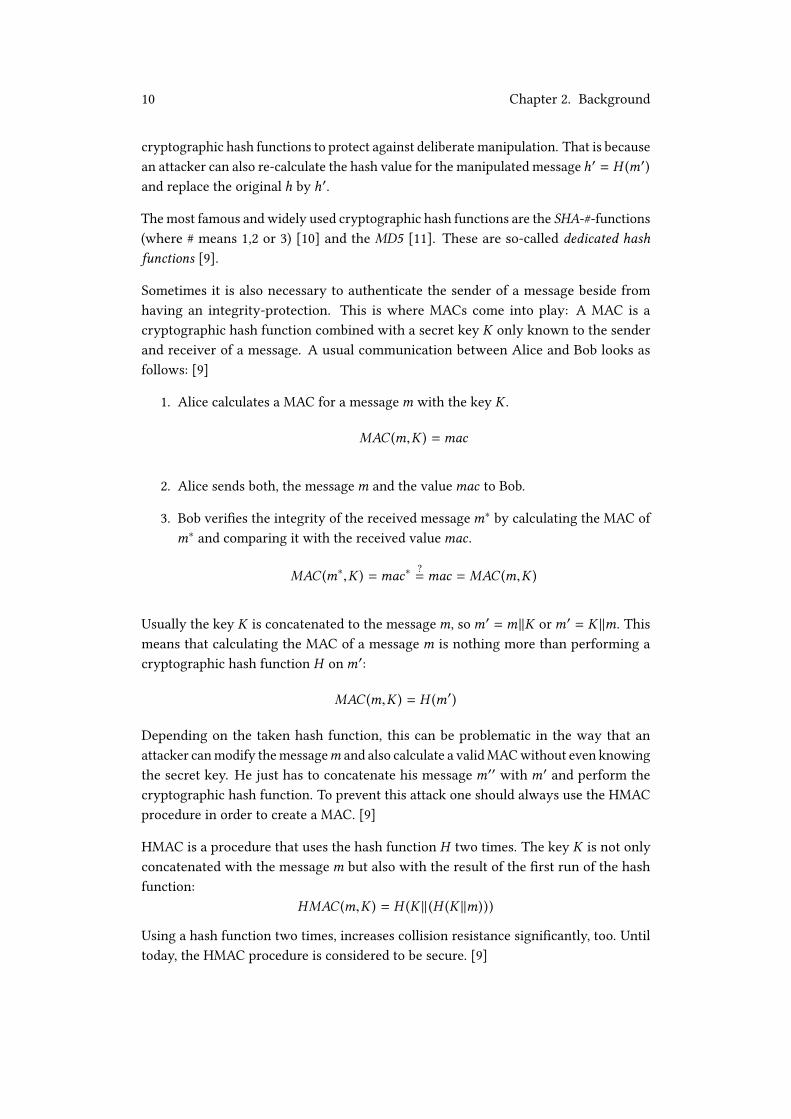
Participating entities are two VMs and the respectiveAdmin Devices. The steps explainedin the following are only necessary when we use a local PKI. The protocol is illustratedin �gure 4.4.
Figure 4.4: Pairing between two VMs based on a PKI
According to �gure 4.4 the two Admin Devices, more precisely the two tenants exchangetheir respective root certi�cates. This step is necessary because the Admin Devices arethe two entities for which a secure connection to the particular VM exists. The receivedroot certi�cates are transferred to the VMs where they are stored. Apart from that, theURLs of the VMs are exchanged. This is required because the URLs contain the domainnames, which are the unique identi�ers.
The idea behind this is best explained in an example: We assume VM 1 wants to sharedata with VM 2 and therefore it connects to VM 2. As mentioned before, the connectionshould be TLS-protected. Therefore, VM 2 authenticates itself with its certi�cate signedby its root CA (Admin Device 2). Due to the fact that VM 1 knows the root certi�cate ofAdmin Device 2 it can verify the authentication and the connection can be established.
The exchange of the two root certi�cates between the two Admin Devices has to happenon an arbitrary side channel. The exchange itself does not have to be con�dentialbecause certi�cates do not consist of any sensitive data. However, the integrity must beveri�ed to prevent Man-in-the-Middle attacks. This can be achieved by telephone, forinstance. This also applies to the exchange of the two URLs of the VMs.
Exchanging certi�cates is not really comfortable for the tenants. However, in a realsituation this is never needed because we assume that we use a global PKI if we basicallydecide to use the solution based on a PKI. In this case, it is only required to exchange

4.2. Pairing based on a PKI 31
the URLs of the VMs, which can be done by telephone. We assume this is acceptablebecause if a tenant wants to share data with another one, it must also be reasonablefor him to make contact with the other person. The example before would then looklike this: VM 1 wants to connect to VM 2. Therefore, VM 2 authenticates itself with itscerti�cate signed by the intermediate CA (Admin Device 2) which again has a certi�catesigned by a global veri�able CA. This way, the authentication can be veri�ed directlyand the connection can be established.
32 Chapter 4. Design

33
Chapter 5
Implementation
This chapter documents the implementation part of this thesis. The concrete protocolthat has been implemented is the MeasrDroid Pairing Protocol between a client anda VM based on a PKI described in section 4.2.1. Due to the fact that no global PKIexisted during the time of development, the solution is based on a local PKI. However,to improve this solution by the use of a global PKI only a few changes are necessary.The implementation required both work on the Android application and on the backend.The steps that are done by the Admin Device were not implemented because this is partof a di�erent work.
5.1 MeasrDroid Core
The MeasrDroid Core is the Android application that has been extended. The workhereby was mainly the client part of the protocol. The programming language wasexclusively Java. For testing purposes the MeasrDroid Application that is available onthe Google Play Store was used [7]. The smartphone used for testing was a rooted HTCDesire S running a Custom-ROM based on Android 4.0.4.
5.1.1 QR-Code Scanner
A really important aspect of the protocol is the QR-Code because all necessary infor-mation is encoded there. This includes the root certi�cate, the shared secret betweenthe Admin Device and the client, the URL of the VM and the client name. The infor-mation is encoded in URI style. This means that the QR-Code is only one String thatcontains all information concatenated with the & sign. An example would look likethis: cert=abcd&secret=1234&url=measrdroid.de&name=client.

34 Chapter 5. Implementation
For the root certi�cate we used a size of 2048 bits. The certi�cate is encoded in the PEMformat. Therefore, it has a size of 1402 characters. The shared secret is a symmetrickey created with a KeyGenerator in Java. It is encoded using the Base64 encoding.Therefore, it has a size of 86 characters. The URL has a size of 26 characters and theclient name has a size of 10 characters. Apart from that, the names of the variables mustbe encoded in order to be able to split the concatenated String in its components again.Therefore, 45 additional characters are necessary. In total, a size of 1569 characters mustbe encoded.
At the time of this writing a QR-Code can store a maximum size of 3Kb [13]. Hence, itis theoretically possible to encode all necessary information in one QR-Code. However,the test smartphone was not able to scan this amount of data. Maybe newer camerasare able to manage this. According to [14] it is not recommended to store more than300 characters in one QR-Code if the QR-Code is meant to be read by a camera of asmartphone. Therefore, we decided to split the root certi�cate into three QR-Codes andused a fourth QR-Code for the encoding of the other information.
For the scanning of the QR-Code a library was used which is called barcodescanner [15].The library is licensed under Apache licence, Version 2 and can therefore be used forfree. It is based on ZXing and ZBar [15]. The library provides an embedded solutionfor scanning a QR-Code without the need of installing any third party scanner applica-tions. Positive is the simplicity of using it. The only thing that needs to be done is toimplement the interface ZXingScannerView.ResultHandler and override the handleRe-sult(Result rawResult) method. In the manifest of the application it must be allowed touse the camera. One negative aspect may be that development is still well underway.Hence, regular updates are quite presumable. Listing 5.1 shows an excerpt of the scannerclass.
1 public class QRScanner extends Activity implements ZXingScannerView.
ResultHandler {
2
3 [...]
4
5 @Override
6 public void handleResult(Result rawResult) {
7 splitRawResult(rawResult.toString());
8 finish();
9 }
10 }
Listing 5.1: Excerpt of QRScanner
The library allows some advanced settings, like automatic focus or �ash. However, thestandard settings are already suitable. When the camera is started and the QR-Code

5.1. MeasrDroid Core 35
is recognized, the method handleResult(Result rawResult) is called. In this context it isenough to only use the String representation of the rawResult because we know thatthe input is just an encoded String of the aforementioned information. The splitRawRe-sult(String rawString) method is a helper method that splits the concatenated String inits components and stores them in the database. MeasrDroid uses the SharedPreferencesfor storing data. This way, stored data is accessible by all components of the applicationbut not for other, installed applications.
Beside the QRScanner class, a ScannerManager class exists which manages all of thescanning. Therefore, it provides a method to actually initiate a scan and ways to checkwhether all needed information has already been scanned. Only if this is true theapplication can move on performing the pairing.
5.1.2 Certi�cate Tools
The Certi�cateTools class is a helper class that enables the creation of a key pair anda CSR. It is also possible to convert a CSR to the common PEM format. According tothe coding conventions of tool classes, everything is de�ned statically here and it is notpossible to create an object of this class.
The creation of the key pair is done by classes and methods from the java.securitypackage. At �rst an instance of a KeyPairGenerator has to be created with the speci�edalgorithm. The object then has to be initialized with the key size in order to generatethe key pair. The algorithm and the key size are de�ned in the PairingManager class.We used RSA as the algorithm and a key size of 2048 bits which is strong enough at thetime of this writing according to NIST [16].
By contrast, creating a CSR is not possible in Java without external libraries. That isbecause a provider is needed that implements the functionalities [17]. We decided touse the Bouncy Castle library because it is probably the most known library relatedto this topic, written in Java [18]. Also, it is free to use and well documented. Onenegative aspect in the eyes of the author is that it is not possible to use all of the neededfunctionalities by just adding one .jar �le. To be exact, two �les have to be included:one for the aspects related to the provider and one for the main aspects of creating aCSR. Listing 5.2 shows the important parts of creating the CSR.

36 Chapter 5. Implementation
1 public static PKCS10CertificationRequest generateCSR(KeyPair pair, String
subject, String algorithm) {
2 PKCS10CertificationRequestBuilder builder = new
JcaPKCS10CertificationRequestBuilder(new X500Principal(subject),
pair.getPublic());
3 ContentSigner signer = new JcaContentSignerBuilder(algorithm).build(
pair.getPrivate());
4 return builder.build(signer);
5 }
Listing 5.2: Excerpt of the creation of a CSR
The method returns an object of the class PKCS10Certi�cationRequest which representsa CSR. The needed parameters are the key pair, the subject and the algorithm which arede�ned in the PairingManager class. The algorithm is used for signing. We used SHA256with RSA encryption. At �rst, a PKCS10Certi�cationRequestBuilder object is createdspeci�ed with the subject and the public key. Secondly a ContentSigner object is createdspeci�ed with the dedicated private key. The build(ContentSigner signer) method �nallycreates the CSR.
The common format of a CSR is the PEM format. To convert the PKCS10Certi�cation-Request to PEM format a second method has been implemented that uses a JcaPEMWriterobject to obtain the desired goal.
5.1.3 HTTP Client
According to the protocol, sending the CSR and the MAC to the VM has to be TLS-protected. Therefore, a HTTPS client is needed. This is already implemented in Measr-Droid. However, since Android 5.1 (Lollipop, API 22) all classes from the org.apache.httppackage have been deprecated [19]. The existing HttpClient class is based on theseclasses. Therefore, a new HTTPS client has been implemented based on HttpsURLCon-nection from the javax.net.ssl package. A customized SSLSocketFactory is speci�ed witha TrustManager that trusts the root certi�cate. The root certi�cate has to be stored inthe KeyStore before.
Due to the fact that posting data to a VM triggers network tra�c, the HttpsPost isimplemented as an AsyncTask [20]. This is necessary in order to prevent the UI-Threadfrom getting blocked because of background tasks.

5.1. MeasrDroid Core 37
5.1.4 Pairing Manager
The PairingManager class is responsible for performing the pairing of the VM and theclient. The class consists of a constructor and one method that does all the needed steps:public boolean doPairing(Context ctx). This is the highest possible encapsulation andallows an easy usage. The only thing that needs to be done is to create an object of theclass and call the doPairing() method. To be exact, this is never done directly but witha service (see 5.1.5). The method returns true if the pairing was successful, otherwisefalse. Everything else is kept private. For correct work a few input variables are needed.These are the application context, the client name, the URL of the VM, the shared secretand the root certi�cate. Apart from the context, all of this information is stored in thedatabase. The PairingManager class also de�nes a few static variables at the very startwhich are needed for all subroutines. This concludes the algorithm for the MAC, thealgorithm for the key pair and the key size. Also, the algorithm for the CSR is de�nedhere and the subject itself where only the client name is added dynamically. Thesevariables can be changed in order to satisfy the own needs.
The steps that are done in the doPairing() method are as follows:
• Store root certi�cate: This step is necessary for the TLS-protected connectionbetween the client and the VM. That is because the VM authenticates itself witha certi�cate signed by the root CA. Therefore, the root certi�cate needs to bestored in the KeyStore so it can be trusted by a TrustManager. The location of theKeyStore is a directory on the �lesystem. A KeyStoreManager already exists inMeasrDroid which is used for this task.
• Generate CSR: This is done using the aforementioned Certi�cateTools helperclass. The CSR is converted to PEM format immediately.
• Calculate MAC: Before the MAC can be calculated the secret has to be createdfrom the encoded String that is already stored in the database. This is done usingclasses and methods from the javax.crypto package. Also, an algorithm for theMAC has to be speci�ed. We used the HMAC procedure based on SHA-1.
• Send CSR and MAC: This is done using the aforementioned HttpClient helperclass. CSR and MAC are stored in a HashMap which is converted to post parame-ters before it is sent.
• Receive certi�cate: When the integrity of the sent CSR is veri�ed by the AdminDevice the certi�cate is created, signed and stored on the VM. From there it canbe pulled by the client together with the MAC. Afterwards the certi�cate is storedin the KeyStore if the calculated MAC matches the received one.

38 Chapter 5. Implementation
5.1.5 Pairing Service
The overall Pairing Protocol can take quite a long time, depending on how fast theAdmin Device signs the CSR and stores the certi�cate on the VM. Therefore, we decidedto use an Android Service. [21] This has the advantage that the user does not have towait the whole time for the application to be �nished. The user can always exit theapplication and come back later on. Once started the service will continue its work untilit is �nished even if the application is closed. Secondly, a service provides an easy wayto perform tasks in the background. This is needed in order to prevent the UI-Threadfrom getting blocked.
The PairingService class simply creates an object of the PairingManager class and callsthe doPairing() method. If something went wrong, it waits for one minute and triesagain until the pairing was successful. The service is managed by an already existingServiceManager class.
5.1.6 Graphical User Interface
The implemented protocol does not really need a Graphical User Interface apart fromthe scanning of the QR-Code. That is because all of the main steps are done in thebackground using the aforementioned service. However, in two situations it appearsto be useful to have a graphical feedback. Firstly, to inform the user of what will bedone during the setup. This is achieved by a simple Wizard Page. Secondly, to havesome kind of a placeholder which prohibits the user from doing something during thetime when the service is running. Therefore, an activity has been introduced. A simplegear animation shows that the service is currently running and a progress bar togetherwith some text informs the user about which step is currently done by the service. Theactivity can not be left, apart from exiting the whole application. When the pairing is�nished it automatically destroys itself and moves on. Figure 5.1 shows two screenshotsof the two mentioned situations.
5.2 MeasrDroid Backend
In this context the MeasrDroid Backend is the VM where CSR and MAC are pushedto and the certi�cate is pulled from. This thesis concentrates only on part of the webdevelopment. Therefore, a framework was used which is called Flask [22]. It is writtenin Python and is based on Werkzeug and Jinja. It is licensed under BSD licence and cantherefore be used for free [22]. The advantages of using a framework like this are easyusage and the fact that not everything needs to be implemented by one’s self. Thisincludes Cookie management or defence against Cross-Site Scripting, for instance [22].

5.2. MeasrDroid Backend 39
(a) Pairing Wizard (b) Pairing Activity
Figure 5.1: Graphical User Interface
40 Chapter 5. Implementation
Also, it is quite easy to implement a routing system based on URLs. Only a specialdecorator needs to be added. Listing 5.3 shows an example of this.
1 @app.route("/")
2 def index():
3 return "MeasrDroid is awesome"
Listing 5.3: Example of URL routing in Flask
The route(path) decorator tells Python to call a speci�ed method when a certain pathis requested. Requesting the index page automatically calls the index() method in thisexample. It is also possible to add more settings to the route decorator, like the allowedmethods (GET, POST).
Flask comes with a simple built-in web server. This is good enough for development andtesting purposes. However, in a real situation it may be better to use a more advancedserver, like Apache.
5.2.1 TLS Protection
Due to the fact that the protocol foresees a TLS-protected connection between the clientand the VM, the server must be able to handle HTTPS. This is also quite easy to achievein Flask. Only the ssl_context variable must be speci�ed in the run() method. This is infact just a tuple of a valid certi�cate and the dedicated private key. The certi�cate issigned by the root CA.
5.2.2 Pairing and User Feedback
The only thing that needs to be implemented in this context is to receive the CSR andMAC and store them in a directory from where the Admin Device can pull them lateron. Flask provides a request object which enables to read from a POST variable. Thecontent of the csr variable is written to a �le and stored in the Uploads directory. Theexact same thing is done with the mac variable.
For user feedback the server sends the HTTP status code back to the client. This caneither be 200 if the upload was successful, or 400 otherwise. Also, a short message isprovided which describes what value is missing in the case of an error.

41
Chapter 6
Evaluation
In this chapter both the theoretical and practical part of this thesis are evaluated undercertain aspects. This chapter also compares the two possible solutions of the MeasrDroidPairing Protocol described in chapter 4.
6.1 Usability
Easy usage is an implicit requirement of every application. If an application is toocomplicated, it is quite unrealistic that the application ever becomes successful.
The parts that have been added to the Android application are directly inserted intothe start wizard. Therefore, the same colour scheme is used and the operation is notmore complicated than it was in the already existing application. In fact, only two userinteractions are necessary: Firstly, accepting the information given in a wizard pageby clicking on a button. Secondly, the scanning of the QR-Code. All of the rest is doneautomatically in the background which is quite comfortable for the user.
The scanning of the QR-Code itself is not really convenient in the current solutionbecause the user has to scan four times. However, this is only because we use a local PKIat the moment as explained in section 5. In a real situation the local PKI will be replacedby a global PKI and in this case there is no need for scanning a whole certi�cate. Thenonly one QR-Code has to be scanned which is reasonable.
6.2 Performance
The overall performance of theMeasrDroid Pairing Protocol in the form it is implemented,depends an a few factors. A major factor is the power and equipment of the smartphone.If the smartphone is only equipped with a camera with low resolution, it may take

42 Chapter 6. Evaluation
longer to recognize and scan the QR-Codes. The smartphone used for testing (HTCDesire S) was introduced in 2011. By comparison to newer smartphones the generalpower and equipment is much worse. However, also in this case it did not take longerthan a few seconds to scan the QR-Codes. Also, the creation of the key pair, the CSRand the calculation of the MAC took only a few seconds. Due to the fact that we used aservice which runs in the background, this depends furthermore on how many othertasks are currently running on the smartphone.
If we assume that the VM is online all the time, the upload of CSR and MAC is alsoreally fast. In our test scenario the sent package had a size of only 1049 bytes. Hence,the upload does not take very long even with a low internet connection.
The further performance depends on how fast the Admin Device becomes active andsigns the CSR. Due to the fact that the Admin Device is not online all the time and isalso not in our area of competence, we can not make any statement about the amountof time in this case. However, in a real situation we assume that the tenant who wantsto register a client immediately performs the necessary steps.
When the certi�cate is stored on the VM, it can take a maximum time of one minuteuntil the smartphone tries to pull again. Then the certi�cate is downloaded, the integrityis veri�ed and it is stored in the KeyStore. This takes only a few seconds again.
In our test scenario the whole pairing took only approximately 3 minutes. An importantaspect is also the fact that the protocol needs to be performed only one time. Afterwardsuploading data to the VM is possible in real-time (see 6.5). Hence, one can say thatthe overall performance of MeasrDroid is much better than before because the mostfrequently step (uploading data to VM) is much more e�cient now.
6.3 Privacy Preservation
As even being part of the title, privacy preservation is a really important requirement ofthis thesis. According to the de�nition in section 2.1 privacy preservation are methodsto obtain privacy.
In this context privacy means that collected data - owned by a tenant - is only accessibleby the particular tenant at any time. This is mainly reached by encryption. Data isalways encrypted on the client device before it is uploaded to the VM. Furthermore, datais only stored in encrypted format. This way, it can be ruled out that any unauthorizedperson is able to gain insights into the tenant’s private data even if the person managesto get access to the VM. The private key for decryption is stored on the Admin Devicewhich is only accessible by the tenant. Hence, the tenant is able to inspect or evaluatecollected data on the Admin Device.

6.4. Evaluation of the Two Solutions 43
Secondly, privacy means that the decision on sharing private data with others can onlybe made by the tenant itself. A tenant can use the Admin Device in order to select partsof the collected data that should be shared with others. Also, the tenant can explicitlydecide to whom selected data should be accessible.
To achieve these two aspects it is required to have a secure, integrity-checked andauthenticated connection in every data transmission from one entity to another one.This thesis concentrates only on the situations when data is sent from a client to aVM (upload) and when data is sent from one VM to another one (sharing). By defaultthere is no possibility to either verify the integrity of a message or to authenticate thesender/receiver of a message. According to the attacker model presented in section 3.4this is susceptible to several attacks. Data can be manipulated during the transmissionand it can not be veri�ed that data is sent to a valid communication partner but not toan attacker.
Therefore, it is necessary to provide a mechanism that enables the establishment of suchan integrity-checked and authenticated connection, which is basically a TLS-protectedconnection. This is achieved by the MeasrDroid Pairing Protocol. After performing theprotocol both communication partner are able to authenticate each other and establishthe secure connection for exchanging data. Hence, it can be ruled out that either thesender of a message is malicious or the receiver. Furthermore, no Man-In-The-Middleattacks are possible.
Hence, the security of the overall system lies in the MeasrDroid Pairing Protocol itself.If the protocol is secure, one can say that no attacks are possible to gain insights intoprivate data during the transmission. This is proven in section 6.4 for both possiblesolutions presented in chapter 4. Due to the fact that data is always sent and stored inencrypted format, one can also say that privacy is obtained in the whole system.
6.4 Evaluation of the Two Solutions
The two solutions presented in chapter 4 are both suitable. Hence, it is worthy tocompare the two solutions to each other. Apart from that, the security models areinvestigated in this section in order to prove that both solutions are secure.
It is useful to provide two possible solutions to achieve the same goals. In general, onecan not say that either solution one is better or solution two. It depends on the situation.
The most common use case is probably that a tenant rents a VM which is managed bythe service provider. Therefore, the whole IT infrastructure is provided by the serviceprovider. This situation basically allows both solutions. Therefore, one can say thatsolution two based on a PKI is more bene�cial here because it has more advantagesaccording to section 6.4.3. However, if a tenant is not willing to pay any money, which

44 Chapter 6. Evaluation
is the most decisive factor in most cases, solution one is also a good opportunity becauseself-signed certi�cates can be created for free.
In general, it is not required that the VM is managed by the service provider. It isalso conceivable that a tenant sets up the whole IT infrastructure at his home. In thiscase it may be better to use solution one based on self-signed certi�cates. If the wholeinfrastructure is not connected to the Internet, it is not even possible to use a globalPKI in this situation.
6.4.1 Investigation of the Security Model (Self-Signed)
The initial connection between the VM and the client or two VMs can not be secured.The security of this protocol lies only in the veri�cation of the integrity of the sentmessages and authentication of the sender. This way it can be proven that the messageswere not manipulated during the transmission and were not sent from an attacker. Thisis achieved by a Message Authentication Code. Hence, the security lies in the sharedsecret between the VM and the client or between the two VMs.
The secret is sent to the VM securely because we assume that the VM is already assignedto the tenant. Hence, a secured connection between the VM and the Admin Devicealready exists. The QR-Code is a secure side channel per de�nition because we assumethat the tenant only provides this information to the particular client he wants to register.This also applies to a di�erent side channel like USB �ash drive, for instance. With thesetwo assumptions in mind we can assume that the shared secret is only known to theVM and the client and the setup for using a Message Authentication Code is thereforesecure.
In the other situation we assume that the agreement on the shared secret has happenedon a secure side channel, like telephone, for instance. Hence, we can assume that theshared secret is only known to the two VMs and again the setup for using a MessageAuthentication Code is secure.
Using a non-con�dential channel for sending self-signed certi�cates is acceptable be-cause certi�cates do not consist of sensitive data. However, the integrity must beveri�able because of Man-in-the-Middle attacks. Assuming that the HMAC procedure issecure, the whole protocol is therefore secure.
6.4.2 Investigation of the Security Model (PKI)
The security of this concept lies mainly in TLS. It is used to secure both the connectionbetween the client and the VM and the connection between the VM and the AdminDevice. We assume that the secure connection between the VM and the Admin Devicealready exists after the point when the VM is assigned to the tenant. Using TLS for the

6.4. Evaluation of the Two Solutions 45
connection between the client and the VM is possible, too because we assume that theVM possesses a valid certi�cate which can be veri�ed by the client.
Under the assumption that TLS is a secure protocol, it can be ruled out that any trans-mitted message is manipulated during the transmission. However, authentication isonly possible for the client at the initial connection but not for the VM. By implication,this means that anybody can generate a CSR and send it to the VM. Apart from that,the message can still be manipulated when it is stored temporary on the VM. Therefore,it is necessary to verify the integrity of transmitted messages and also authenticate thesender. This is achieved by the Message Authentication Code based on a shared secretbetween the Admin Device and the client. Hence, the further security lies in the sharedsecret.
The secret is encoded in a QR-Code. The QR-Code is a secure side channel per de�nitionbecause we assume that the tenant only provides this information to the particularclient he wants to register. This also applies to a di�erent side channel, like USB �ashdrive, for instance. Hence, we can assume that the shared secret is only known to theAdmin Device and the client and the setup for using a Message Authentication Code istherefore secure.
Assuming that the HMAC procedure is secure, the whole protocol for the pairing of aclient and a VM is therefore secure.
For the pairing of two VMs only non-sensitive data has to be exchanged. These arecerti�cates (only local PKI) and URLs (local and global PKI). This is also no securityleak if we assume that the integrity of the sent messages are veri�ed by the respectivetenants. The exchange itself can happen on an arbitrary side channel.
6.4.3 General Comparison
This chapter compares the two provided solutions in general and independently fromthe situation.
Advantages of solution one based on self-signed certi�cates:
• Direct connection: The main conversation is either between a client and a VMor between two VMs. In both situations there is a bidirectional, direct connection,whereas solution two has to use the VM for redirecting transmitted messages.
• Smaller QR-Code: There is no need to encode a whole certi�cate in a QR-Code.Hence, this solution can get along with just one QR-Code which is convenient forthe client. However, this is only an advantage over solution two if we assumethat solution two is based on a local PKI which is probably never the case in areal situation.

46 Chapter 6. Evaluation
• Costs no money: Self-signed certi�cates can be created with free tools. Hence,this solution does not cost any money, whereas solution two can be very expensiveif every Admin Device needs a certi�cate signed by a globally veri�able CA.
Advantages of solution two based on a Public Key Infrastructure:
• Based on TLS: TLS is currently the international industry standard for securecommunication. TLS is used to secure all transmitted messages during the per-formance of the protocol. As a consequence, it is also easier for foreigners tounderstand the security model of this solution.
• No need for storing client certi�cates: The VM does not have to store anyclient/VM certi�cates which saves memory. Also it is more performant to onlyauthenticate a client/VM by verifying the root certi�cate, instead of lookingthrough all stored client/VM certi�cates.
• Scalability: Based on the previous aspect authentication stays the same in perfor-mance even with more than 100 valid clients/VMs because only the root certi�catemust be veri�ed. In solution one this requires to look through more than 100certi�cates.
• Easy extensibility: If money is a decisive factor, this solution can simply bebased on a local PKI which costs no money. However, improving this solution bythe use of a global PKI is possible without many changes and should always bepreferred because of other advantages.
• Easy protocol: If we assume that we use a global PKI, the pairing between twoVMs is very easy to achieve. The only step that is required is the exchange of theURLs which is done directly by the tenants. Therefore, no further implementationis necessary, too.
Both solutions have their advantages and can be used in a real situation. However,advantages of solution two are considered to be more strong. This is mainly becauseof easy extensibility and scalability. If the protocol is only needed in order to registerone client, the performance of the system after performing the protocol is nearly thesame in both solutions. However, using solution two, the system is also performant inthe case of more than 100 registered clients. Therefore, solution two was taken for theimplementation described in chapter 5.
6.5 Real-Time Data Collection
As mentioned in section 1.3 real-time data collection is one of the desired goals of thisthesis, more precisely of the whole new concept of MeasrDroid.

6.5. Real-Time Data Collection 47
This was not possible in the old version of MeasrDroid due to security reasons. That isbecause a client was not able to directly push data to the database where it is stored.Instead, it was only possible to push data to the Upload.droid from where it is pulledafter a certain time by the C3PO. The reason for this is that the C3PO does not need tobe accessible on the internet which is probably the highest possible level of security.This way, most attacks against an IT system can be warded o�. However, as explainedin section 2.2.3 the time steps between two pulls can not be made arbitrary small whichmakes real-time data collection impossible.
In the new version of MeasrDroid real-time data collection is possible because everyclient can directly push data to the VM where it is stored. This means that uploadingdata from a client to the location where it is stored is no longer done by polling, butis event-based. This is the fastest possible solution because the only delay that mayappear is due to network tra�c.
However, allowing clients to directly push data to the VM is only possible because theVM is accessible on the Internet. This looses up the former security concept because ingeneral, this enables two kind of attacks:
1. Distortion of Data: If every client is allowed to directly send data to the VM, anattacker could also distort collected data by uploading senseless data to the VM.
2. General Attacks against the VM: All conceivable attacks against a server,which is accessible on the Internet, can be performed against the VM, as well.This could be attempts to cripple the whole VM or to get access to it. If an attackermanages to get access to the VM, he has also access to all stored data.
Hence, a new protection mechanism is required in order to ward o� these attacks.This is mostly achieved by the MeasrDroid Pairing Protocol. The protocol enables theestablishment of a TLS-protected connection with mutual authentication. Therefore,the VM can be con�gured to never accept a connection with a client for uploading dataif the client is not able to authenticate himself. If the client has performed the protocolsuccessfully, he is able to authenticate himself and establish a connection. This meansthat attack 1 can be completely warded o� only because of the MeasrDroid PairingProtocol.
For attack 2 the argumentation is nearly the same. The only problem is that the VM cannot be con�gured to never accept a connection in general. This is due to the fact that itmust be possible for a client to either send his self-signed certi�cate or the CSR to theVM. However, it is not realistic that many attempts to perform the pairing appear in ashort time. Therefore, the VM can be con�gured to only accept a few connections perday, for instance or use an IP blacklisting/whitelisting in order to prevent Dos attacks.Apart from that, common security aspects like Intrusion Detection Systems and Firewallsare in place to generally protect the VM against attackers. However, this is part of adi�erent work and is therefore not investigated in this thesis.

48 Chapter 6. Evaluation
Under the assumption that the mentioned security aspects are applied correctly, thefurther security lies only in the protocol itself. Due to the fact that the protocol is secure,as proven in section 6.4 one can say that the overall system is not more insecure than itwas before and therefore real-time data collection is now possible without underminingthe common security concept.

49
Chapter 7
Related Work
This chapter gives an introduction to other work that is related to this thesis.
There are many bachelor -and master theses related to the original MeasrDroid project.A selection can be found in [6]. Of course, these theses are also related to this work.However, this is not investigated in this chapter.
A paper that introduces a related topic is called Multi-tenant Databases for Software asa Service: Schema-Mapping Techniques, written by A. Kemper et al. and was published2008 [23]. The authors describe a new schema-mapping technique which is multi-tenantcapable. This technique is called Chunk Folding. The idea is that "logical tables arevertically partitioned into chunks that are folded together into di�erent physical multi-tenant tables and joined as needed" [23]. Transferred to our context, this means that noisolated virtual machines are necessary in order to achieve multi-tenancy. Instead, thereis only one server where all collected data is pushed to and multi-tenancy is achievedby the special schema-mapping technique. This is an interesting approach. However,it is not really suitable for our requirements, especially not for privacy-preservation.This is because the service provider learns all data collected by all of the clients andtenants, respectively. Instead, we require that each particular tenant is the only partywith access to the collected data.
A second paper that is related to this work is called CloudVisor: Retro�tting Protection ofVirtual Machines in Multi-tenant Cloud with Nested Virtualization, written by F. Zhanget al. and was published 2011 [24]. The situation in this paper is nearly the sameas in our context: virtual machines are used in order to achieve multi-tenancy. Theauthors present the statement that "software stacks in typical multi-tenant clouds arenon-trivially large and complex, and thus are prone to compromise or abuse fromadversaries including the cloud operators" [24]. In simpler words, this means that virtualmachines can be attacked and exploited. The authors developed a system for securitymonitoring which is based on nested virtualization. The prototype implementationis called CloudVisor and is mainly "responsible for protecting privacy and integrity

50 Chapter 7. Related Work
of resources owned by VMs" [24]. As often mentioned in this thesis, security plays amajor role in order to obtain privacy which is the central requirement of this project.Therefore, the paper has also importance for our project but in fact, it is not required inour situation. The main idea of CloudVisor is to �lter and monitor every access to theVM. If anybody - even the service provider - tries to get access to the data owned by theVM, he "can only see the encrypted version of that VM’s data" [24]. This means thatthe best security guarantees (apart from integrity-checks) of CloudVisor are to nevermake data available to anybody in plain format. However, in our solution data is neverstored in plain format. Hence, a monitoring tool like CloudVisor is not required.
Related to our project are also all kind of platforms where a user can upload personal dataand evaluate it later on. An example for this is Runtastic. Runtastic is an austrian start-upfounded in 2009 which was sold to Adidas in 2015 [25]. The idea of Runtastic is that everyuser can measure several aspects related to sports training (pulse, calories, kilometres,etc.) with a smartphone and upload it to the Runtastic platform where it is stored [26].The goals are mainly to motivate users to do more sports. Therefore, uploaded data canbe evaluated or shared with others in order to enable a comparison [26]. This is exactlythe same which can be done in our project. However, there is one big di�erence: Due toprivacy preservation in our project it is guaranteed that even the service provider hasno access to uploaded data. This is not the case in a commercial platform like Runtastic.According to the privacy explanation the provider is explicitly allowed to collect personaldata of its users and use the data for purposes of the Runtastic application [27]. However,the data is not transmitted to any third-parties [27].

51
Chapter 8
Conclusion and Outlook
This thesis is part of a bigger project. The entire project is to introduce multi-tenancyin MeasrDroid in a privacy-preserving way. Therefore, the overall architecture andstructure of MeasrDroid has changed. Virtual machines are introduced in order toprovide individual data sinks for each tenant. A tenant can have an arbitrary numberof clients as data sources. Every client is able to upload collected data to the VMwhere it is stored con�dentially. Furthermore, new concepts are introduced like sharingmechanisms between two tenants.
Privacy is the central requirement of the whole project. To obtain privacy data isnever sent or stored in plain format but always encrypted. As a consequence it isnot possible for unauthorized people to ever gain insights into some tenant’s privatedata. Furthermore, privacy preservation requires the presence of an authenticatedand integrity-checked connection for every data transmission. The MeasrDroid PairingProtocol has been developed to enable the establishment of such a connection. Theprotocol needs to be performed before data is sent from one entity to another one andcan therefore be seen as the initial pairing. As a side e�ect, it enables real-time datacollection which has not been possible in the existing MeasrDroid project.
This thesis provides two di�erent solutions for the MeasrDroid Pairing Protocol. The�rst solution is based on self-signed certi�cates, whereas the second solution is basedon a PKI. Both solutions are suitable and secure which is proven in the thesis. Apartfrom providing the theory, the MeasrDroid Pairing Protocol has also been implementedin the form based on a PKI.
Currently there are two further students involved into the project: The �rst one ismainly responsible for the management of the VMs. This includes the VMLCS as it iscalled in �gure 3.2 in section 3.2. The second one is mainly responsible for the webdevelopment of the VMs and the Admin Device. This includes user management or thesteps in the protocol that are done by the Admin Device. Next, we also have to thinkabout ways how to encrypt sensor data on the client device in order to e�ciently enable

52 Chapter 8. Conclusion and Outlook
partial sharing with other tenants. This could be achieved by the use of Attribute BasedEncryption.
All in all the project is very interesting and �rst steps are already done. However, a lotmore things need to be done in order to have a multi-tenant MeasrDroid that is readyfor the market.

Appendices
53


55
Appendix A
Abbreviations
• CA: Certi�cate Authority
• CRL: Certi�cate Revocation List
• CSR: Certi�cate Signing Request
• HMAC: Keyed-Hashed Message Authentication Code
• HTTP: Hypertext Transfer Protocol
• HTTPS: Hypertext Transfer Protocol Secure
• MAC: Message Authentication Code
• MD5: Message Digest 5
• NIST: National Institute of Standards and Technology
• PKI: Public Key Infrastructure
• SHA: Secure Hash Algorithm
• SSL: Secure Sockets Layer
• TLS: Transport Layer Security
• UI: User Interface
• URI: Uniform Resource Identi�er
• URL: Uniform Resource Locator
• VM: Virtual Machine
• VMLCS: Virtual Machine Lifecycle Service

56 Appendix A. Abbreviations

57
Appendix B
Glossary
• Admin Device: The Admin Device is the tenant’s device with direct access to theparticular VM. It is meant to be the control center of MeasrDroid for the respectivetenant. Collected data can also be inspected and evaluated here.
• Android: Android is an operating system for smartphones. Android is based onLinux and is open source. Applications for Android are usually written in Java.
• CA: A Certi�cate Authority is an organisation that signs digital certi�cates.
• Client: A client is basically a device that uses some service of an IT-system. Inthis context, client always means smartphone.
• CSR: A CSR is kind of a precursor of a digital certi�cate. It contains all informationrelated to the person for which the certi�cate is issued. This especially concludesthe public key.
• Digital Certi�cate: A digital certi�cate is a signed piece of data that maps theidentity of somebody to the public key. A certi�cate can either be self-signed orsigned by a Certi�cate Authority.
• MAC: A MAC is a calculated value for a given message which enables both, theveri�cation of the integrity of the message and the authentication of the sender.
• MeasrDroid Backend: The MeasrDroid Backend is the counterpart to the Meas-rDroid Core. This concludes basically everything that is part in the architectureof MeasrDroid apart from the client.
• MeasrDroid Core: The MeasrDroid Core is the Android application that has tobe installed on the device in order to measure sensor data.
• PKI: A PKI contains all parties that are necessary in order to create, distributeand verify digital certi�cates.

58 Appendix B. Glossary
• Privacy: Privacy is the area in which a person can decide to whom, when andwhy information is accessible.
• QR-Code: A QR-Code is a two-dimensional code which can be used to storetext. A QR-Code can contain a maximum of 3Kb. [13] In order to read a QR-Codespeci�c scanner applications are necessary.
• Smartphone: A smartphone is a mobile phone with more possibilities than aconventional mobile phone. This concludes e.g. navigation, email, etc. [3]
• TLS: TLS is a protocol for secure communication. It contains authenticationof the communication partner, con�dential end-to-end data transmission andveri�cation of the integrity of sent data.
• VM: A VM is a computer system that is not installed on a real hardware but runsin an isolated virtual environment of a real computer system. It can either havecomplete, partial or no access to the hardware. [28]

59
Bibliography
[1] “Statista - Prognose zur Anzahl der Smartphone-Nutzer weltweit von2012 bis 2019,” http://de.statista.com/statistik/daten/studie/309656/umfrage/prognose-zur-anzahl-der-smartphone-nutzer-weltweit/, Accessed: 2015-12-31.
[2] “Statista - Weltbevölkerung von 1950 bis 2015,” http://de.statista.com/statistik/daten/studie/1716/umfrage/entwicklung-der-weltbevoelkerung/, Accessed: 2015-12-31.
[3] “Smartphone,” Website, http://wirtschaftslexikon.gabler.de/De�nition/smartphone.html, Accessed: 2016-01-07.
[4] P. D. L. Prechelt, “Vorlesung Anwendungssysteme: Privatsphäre,” http://www.inf.fu-berlin.de/inst/ag-se/teaching/V-AWS-2011/31_Privatsphaere.pdf, Accessed:2016-01-05.
[5] “MeasrDroid,” Website, http://www.droid.net.in.tum.de/, Accessed: 2015-12-08.
[6] M. Faath, “Analysis of content delivery networks with an android-based mea-surement framework,” Master’s Thesis, Technische Universität München, Munich,Germany, 2013, advised by Dipl.-Inf. Johann Schlamp.
[7] “Measrdroid on the Google Play Store,” Website, https://play.google.com/store/apps/details?id=de.tum.in.net.measrdroid.gui.stats, Accessed: 2015-12-07.
[8] “Public-Key Cryptography Standards (PKCS) 1: RSA Cryptography Speci�cationsVersion 2.1,” Website, https://tools.ietf.org/html/rfc3447, Accessed: 2015-12-08.
[9] C. Eckert, IT-Sicherheit, 8th ed. Oldenburg Verlag, Jan. 2013.
[10] “Secure Hash Standards,” http://nvlpubs.nist.gov/nistpubs/FIPS/NIST.FIPS.180-4.pdf, Accessed: 2016-01-06.
[11] “MD5,” Website, https://www.ietf.org/rfc/rfc1321.txt, Accessed: 2016-01-06.
[12] K. Schmeh, Kryptogra�e, 5th ed. dpunkt.verlag, Feb. 2013.
[13] “QR-Code,” Website, http://qrcode.meetheed.com/question7.php, Accessed: 2015-12-08.
60 Bibliography
[14] “QR Code Generator,” Website, http://goqr.me/de/, Accessed: 2016-01-12.
[15] “Barcode Scanner Library,” Website, https://github.com/dm77/barcodescanner, Ac-cessed: 2015-12-07.
[16] “Cryptographic Key Length Recommendation,” Website, http://www.keylength.com/en/4/, Accessed: 2015-12-08.
[17] P. Lipp, J. Farmer, D. Bratko, W. Platzer, and A. Sterbenz, Sicherheit und Kryptogra-phie in Java, 1st ed. Addison-Wesley, Jul. 2000.
[18] “The Legion of the Bouncy Castle,” Website, https://www.bouncycastle.org/, Ac-cessed: 2015-12-08.
[19] “Android 5.1 APIs,” Website, http://developer.android.com/about/versions/android-5.1.html, Accessed: 2015-12-08.
[20] “AsyncTask,” Website, http://developer.android.com/reference/android/os/AsyncTask.html, Accessed: 2015-12-08.
[21] “Services,” Website, http://developer.android.com/guide/components/services.html, Accessed: 2015-12-08.
[22] “Flask,” Website, http://�ask.pocoo.org/, Accessed: 2015-12-08.
[23] S. Aulbach, T. Grust, D. Jacobs, A. Kemper, and J. Rittinger, “Multi-TenantDatabases for Software as a Service: Schema-Mapping Techniques,” SIGMOD ’08Proceedings of the 2008 ACM SIGMOD international conference on Management ofdata, 2008, http://wwwkemper.informatik.tu-muenchen.de/research/publications/conferences/sigmod2008-mtd.pdf, Accessed: 2016-01-08.
[24] F. Zhang, J. Chen, H. Chen, and B. Zang, “CloudVisor: Retro�tting Protectionof Virtual Machines in Multi-tenant Cloud with Nested Virtualization,” SOSP’11 Proceedings of the Twenty-Third ACM Symposium on Operating Systems Prin-ciples, 2011, http://www.sigops.org/sosp/sosp11/current/2011-Cascais/printable/15-zhang.pdf, Accessed: 2016-01-08.
[25] “Adidas kauft Runtastic,” Website, http://wirtschaftsblatt.at/home/boerse/europa/4794623/Adidas-kauft-Runtastic_Ein-Deal-mit-perfektem-Timing, Accessed:2016-01-13.
[26] “Runtastic,” Website, https://www.runtastic.com/de/ueber, Accessed: 2016-01-13.
[27] “Runtastic Datenschutz,” Website, https://www.runtastic.com/de/datenschutz, Ac-cessed: 2016-01-13.
[28] “Virtuelle Maschine,” Website, http://www.itwissen.info/de�nition/lexikon/Virtuelle-Maschine-VM-virtual-machine.html, Accessed: 2016-01-07.