techniques and applications of production planning in electronics
TRANSCRIPT

Techniques and Applications ofProduction Planning inElectronics ManufacturingSystems
Jouni SmedMika JohnssonTommi JohtelaOlli Nevalainen
Turku Centre for Computer ScienceTUCS Technical Report No 320December 1999
ISBN 952-12-0577-6ISSN 1239-1891

Abstract
Electronics industry is a major part of modern manufacturing, and elec-tronic systems play an increasingly important role in a majority of today’sproducts. Electronic systems are usually implemented with printed circuitboards (PCBs), and, consequently, PCB assembly has become an importantsector of the electronics manufacturing industry overall. However, operatingeffectively in this industry is becoming more difficult as the companies mustcompete with high quality standards, rapidly changing technologies, shortproduction cycles, and increasing product variety and complexity. In addi-tion, the capital equipment cost of electronics assembly industry facilitiesare high in comparison to the usual turnover of a company. As a result,production planning decisions need to made more and more frequently dueto continuous changes in the production conditions.
In this work we discuss production planning in electronics assembly—and,in particular, in PCB assembly. Our intention is to identify the typical prob-lems arising from production planning and to give a survey of the solutionmethods suggested in the literature. In addition to this theoretical perspec-tive, we will briefly review applications designed for production planning inPCB assembly.
This work is organized as follows: We begin with an introduction to flexi-ble manufacturing systems in general and present a framework for productionplanning systems in Section 1. Next, we study the fundamentals of PCB as-sembly process in Section 2 and survey the relevant literature in Section 3.In Section 4 we review existing commercial applications for production plan-ning, and in Section 5 study more closely one of these systems. Finally, inSection 6 we sum up the discussion and outline few important topics for thefuture research.
Keywords: production planning, printed circuit boards, electronics assem-bly, flexible manufacturing systems
TUCS Research GroupAlgorithmics

1 Introduction
Let us begin our discussion by recalling some basic concepts of industrialproduction. Five basic types of production operations can be classified ac-cording to the degree repetitiveness involved [20]: project, jobbing, batch,flow, and process. The project form includes large-scale complex products,and it involves the allocation and coordination of large-scale input to achievea unique product. Jobbing describes a situation where the manufacturing ofa whole product is considered as one operation and the work must be com-pleted on each product before starting on the next. In the batch form, thevolume of products to be manufactured is larger than in jobbing. A regularand consistent demand for a product such that the item can be produced forstock identifies the flow production. Lastly, the process production requiresthat the material is involved in a continuous process.
The type of production affects also the plant layout. There are three basicforms of layout [20]: process, product, and group. The process layout, inwhich all the plants associated with a particular type of process are groupedtogether, is typical in jobbing and batch production. In the product layout,which occurs in flow and process forms of production, the plant is laid outaccording to the sequence of processes required by the product. A group (orcellular) layout is typical in batch production, and it involves the recognitionthat many of the products have similarities in their makeup and they canthus be grouped into (product) families.
There are two basic principles for decomposing a manufacturing facil-ity into subsystems: decomposition based on processes and decompositionbased on products [42]. Process based facility decomposition leads to equip-ment being arranged into functional machining areas (work centers) dedi-cated to general manufacturing processes (i.e., job shop). Process planningis the systematic determination of the detailed methods by which parts canbe manufactured from raw material to finished products. Computer-aidedprocess planning (CAPP) determines a set of instructions and machiningparameters required to manufacture a part and prepares data for productionplanning and scheduling activities [85]. As Zijm and van Harten [120] ob-serve, CAPP bridges the gap between computer aided design (CAD) andcomputer aided manufacturing (CAM), and thus CAPP represents the “/”in CAD/CAM. Process control refers to the automatic monitoring and con-trol of a process by an instrument or system configured or programmed torespond appropriately to process feedback [102].
Product based decomposition utilizes the principle of group technologyby dedicating machines to cells in order to produce the associated familiesof parts (i.e., cellular manufacturing). Production planning refers to the
1

process of establishing strategies for producing finished products so that man-ufacturing resources are used efficiently. When there is a large number ofproduction variables and a long planning horizon, the problem can be ap-proached by breaking it hierarchically into a series of decision levels [109].Production control is the systematic planning, coordination and direction ofall manufacturing activities to ensure that products (of adequate quality) aremade on time and at reasonable cost [102]. To summarize, in productionplanning we first make a plan anticipating the future events and after thatfollow the plan, whereas in production control we simply react to the eventsas they occur during the production.
In the remainder of this section we discuss flexible manufacturing systems(FMSs) in Section 1.1, and develop a common methodology for buildingpractical production planning systems in FMSs in Section 1.2.
1.1 Flexible Manufacturing Systems
In the late 1950s, several ideas for improving manufacturing began to sur-face. One of the earliest was the idea of group technology for manufacturerswho had to make a variety of different but similar parts. In some types ofindustry—for example, chemical and oil-refining industries—automated man-ufacturing has a long history, but in the batch-manufacturing industries—likethe metalworking industry and the electronics industry—the concept of auto-mated manufacturing was introduced in the early 1970s. By then, a numberof technological developments, in particular flexible manufacturing systems,offered solutions to the problems of job shop environments.
Automated manufacturing has a wide variety of potential benefits to offer.One of the most important advantages is the increased ability to respond tochanges in demand and changes in the products, which is essential in thetoday’s view of short production cycles. Other advantages include shorterlead times, reduction in the work-in-process levels and improved machineutilization. At the same time it is not an easy task to fully attain thesepossibilities, because the reality of the shop floor rarely coincides with thetheoretical models (as we shall see in Section 1.2.1).
A flexible manufacturing system (FMS) aims at achieving a similar level ofeffiency for manufacturing several different product types as in the mass pro-duction of a single product type. An FMS comprises a group of programmableproduction machines integrated with automated material handling equipmentwhich are under the direction of a central controller to produce a variety ofparts at non-uniform production rates, batch sizes and quantities [53]. Themachines or work stations are used to perform operations on parts, and eachoperation requires a number of tools that can be stored in the limited capac-
2

ity tool magazine of the machines. An automatic tool interchanging deviceswitches the tools during production. Because this interchange is relativelyquick, the machine can perform several operations with virtually no setuptime between the operations, if the required tool is present in the tool mag-azine.
Electronics assembly (especially printed circuit board assembly) plantsare usually FMSs. However, the terminology associated with FMS, whichoriginates from metal industry, can be somewhat confusing when applied toelectronics assembly. For example, the concept of ‘tool’ refers to a feeder,which contains the electronic component to be mounted, rather than theactual tool (or nozzle) which does the printing operation. We discuss thetechnical aspects of electronics assembly at greater length in Section 2.
The most prevalent analytical approach to real-time FMS control at-tempts to hierarchically decompose the problem into a number of more easilymanageable subproblems, which relate to a variety of decisions concerninglong-term, medium-term or short-term planning. One of the main reasons fordecomposing the general planning problem is that this problem is too com-plex to be solved globally, whereas it is easier to solve each subproblem one ata time. The solution to the global problem can then be obtained by solvingthe subproblems successively. Naturally, this solution is not likely to be glob-ally optimal, even if all subproblems are solved to optimality. Nonetheless,this approach is a productive and popular way to tackle hard problems.
A typical hierarchical classification scheme of FMS [28] discerns
1. strategic level or long-range planning which concerns the initial deploy-ment and subsequent expansion of the production environments (e.g.,the design and selection of the equipment and of the products to bemanufactured),
2. tactical level or medium-range planning which determines the allocationpatterns of the system production capacity to various products so thatexternal demands are satisfied (e.g., by solving batching and loadingproblems), and
3. operational level or short-range planning which coordinates the shopfloor production activities so that the higher level tactical decisions areobserved (e.g., by solving release and dispatching problems).
Maimon and Shtub [82] and Johnsson [54] relate these objectives to electron-ics assembly: In the strategic level, the planning focuses on determining thebest set of production equipment for the operation (e.g., running a simulationon how much money should be invested in new equipments and what kind
3

of machines should be purchased [35]). These decisions are usually made oneconomical basis, and they are revised over long operational periods, typicallymeasured in several months [34, 66]. At the tactical level, the decisions con-cern machine and line configurations, production schedules, batch sizes, andwork-in-process levels. Finally, the operational level addresses the day-to-dayoperation of the equipment (e.g., how to manufacture a product). The tacti-cal and operational problems have to be solved frequently, and, consequently,the existing production planning systems concentrate on these levels.
Notwithstanding the similarities, there are also differences between PCBassembly and FMSs. Klegka and Driels [66] study four cases of PCB as-sembly and conclude that FMS analysis is inappropriate for PCB assemblysystem analysis: FMS analysis chooses among multiple paths through man-ufacturing systems, and the best path depends on the state of the systemthat is changing as the workload changes. In PCB assembly, however, theproduction cycle is fixed (e.g., receiving inspection, panel preparation, screenpaste, paste volume inspection, component placement, solder joint reflow, vi-sual inspection, and X-ray inspection) and that results a single, sequential,and somewhat deterministic manufacturing process. Hence, a linear costmodel may be adequate to evaluate and identify the cost elements of a PCBmanufacturing system.
Zhou and Leu [119] list three features of PCB assembly distinct fromconventional systems for automated assembly of mechanical parts:
1. each PCB requires numerous insertions, and the activities for eachboard are highly repetitive;
2. there is no strict sequence which has to be followed, and the componentscan be inserted (almost) in any order (i.e., they have no or just a fewprecedence constraints); and
3. only a single manipulator can operate at the time on the board even ifthe machine has multiple manipulators (e.g., see [46]).
Jain et al. [52] discuss setup problems in FMSs and PCB assembly. Theytranslate the tool setup problem of FMSs into PCB assembly system andshow that the FMS formulation is a relaxed version of PCB component setupproblem: In PCB assembly the tooling is more constrained due to the re-strictions on the width of the component reels.
1.2 Production Planning in FMSs
Despite the differences mentioned earlier, we will, for the remainder of thissection, regard PCB assembly as an FMS. In Section 1.2.1, we begin with a
4

discussion of the common problems apparent in the theoretic approaches toconstruct a practical production planning system. After that in Section 1.2.2,we suggest a methodology for overcoming these problems and describe ageneral framework for modeling production planning problems.
1.2.1 Problems in Constructing a Practical Production PlanningSystem
According to Ammons et al. [9] the control of an FMS requires a complexinteraction of two components:
1. computers to perform automated control and routing activities, and
2. humans to supervise the automation, to monitor system flows and out-put, to intervene in the unexpected operation of the system, and tocompensate the effect of unanticipated events.
Especially in dynamic production environments (i.e., in FMSs which are sub-ject to limited resources, random machine failures or multiple optimizationcriteria) the problem of controlling and scheduling the production processis best tackled by a synergy of the computer’s scheduling algorithms andthe human’s effective internal heuristics. In this “interactive scheduling” theproduction planner remains in control and is able to affect the schedulingprocess by using his experience and intuition via computer support. In otherwords, the production planning system should act as a decision support forthe production planner.
However, literature references to practical systems where this interactionhas been realized are rare, and the models—even if based on reality—tend tobe oversimplified. According to Saygin et al. [96] the existing software toolsare typically (1) too slow and cannot react to changing dynamic shop floorconditions, (2) based on simplistic formulations of the reality that ignoreimportant constraints, (3) based on a single objective function or simplistictrade-offs, and (4) difficult to install and integrate into preexisting commer-cial shop floor systems. In general, the gap between theory and practice canusually be attributed to the following factors:
• Researchers fail to address the right problems.
• The given solutions are too complex to use.
• Findings are presented in terms that are foreign to the practitioners.
• Researchers focus on certain problems and omit other, often more im-portant issues.
5

• The realities of the shop floor are ignored.
As Johnsson notes [54], these observations are valid in electronics assembly,where problems are usually tackled by first modeling an existing problem,then finding a solution method to the problem, and after that validatingboth the solution method and the model by solving some randomly generatedartificial test cases. However, this approach does not shed much light on thepracticality of the method.
In addition to interactivity, real-world scheduling problems usually dif-fer (and often quite radically) from the mathematical models presented inliterature. Pinedo lists twelve differences [91]:
1. Theoretical models assume that the scheduling problem is static, where-as in the real world new jobs to be scheduled can emerge at any timeand the schedule is constructed without a perfect knowledge of thenear future. The production environment is dynamic by nature (e.g.,jobs may arrive unexpectedly, urgent prototype series may cut in thepredefined sequence, machines may break down or have a temporaryreduction in the production rate, or the required components may notbe available at the present time).
2. Resequencing problem is rarely addressed in literature even though itis present in most of the actual problems. Production planning is basedon a rolling horizon, which leads to rescheduling or reactive scheduling,where the schedule is constantly updated and revised to meet eventsoccurring randomly.
3. In the real world, production environments are more complicated thanthe models presented in literature, which often disregard machine, joband time dependent processing restrictions and constraints.
4. The mathematical models assume that the weights or priorities of thejobs are fixed and do not change over time; in practice, the weight ofa job often fluctuates over time (e.g., a low-priority job may becomesuddenly a high-priority job).
5. Preferences are usually not taken into account in mathematical models.In reality, even if a job can be scheduled on a given machine, there maybe a preference to schedule it on another one.
6. Most theoretical models overlook the machine availability constraintsand assume that machines are available at all times, whereas the real-world production plants have deterministic and random processes which
6

prevent machines from operating (e.g., shift patterns, preventive main-tenance, breakdowns and repairs).
7. Most penalty functions considered in the literature are piecewise linear(e.g., the tardiness of a job or the unit penalty), whereas, in practice,there usually exists a committed duedate.
8. Theoretical research tends to focus on models with a single objective. Inthe real world, there are usually a number of objectives, whose weightsmay vary over time and may even depend on the subjective preferencesof the production planner in charge.
9. In practice, whenever the workload appears to be excessive and the due-dates appear to be too tight, the problem can be tackled by assigningextra shifts and scheduling overtime.
10. The stochastic models studied in the literature usually assume specialprocessing time distributions (e.g., exponential distribution). In auto-mated assembly, the processing time is fixed with a very high proba-bility, and with a very low probability there is an additional randomtime that is exponentially distributed with a very large mean (i.e., ifa robot performs a task, the processing time is fixed, and if, by acci-dent, something goes wrong, the processing time immediately becomessignificantly larger).
11. Successive processing times on the same machine tend to be highlypositively correlated in practice, whereas theoretical models usuallyassume that all processing times are independently drawn from givendistributions.
12. In practice, the processing time distribution may be subject to changedue to learning or deterioration.
In spite of the differences between the real-world and the mathematical mod-els, Pinedo notes that the general consensus is that the theoretical researchdone in the past has not been in vain, but it has provided valuable insightsinto many scheduling problems. These insights have proven to be useful inthe development of the algorithmic framework for a large number of real-world production planning systems.
1.2.2 Structure of a Production Planning System
The methodology for solving the production planning problems can be di-vided into four stages:
7

1. Familiarization with the problem environment.
2. Modeling the problem.
3. Designing and implementing algorithms to solve the modeled problem.
4. Integrating the algorithm to an existing system or including it in a newsystem.
The far-reaching decisions made in the initial stages influence the overall us-ability of the system. For example, if the model fails to represent the impor-tant aspects of the real-world problem, no algorithm (no matter how cleverlydesigned and effectively implemented it is) can give results which would sat-isfy the production planner. In our experience, this modeling process cannotbe overlooked nor its importance underestimated: A poor algorithm solv-ing an accurately modeled problem gives better real-world results than anaccurate algorithm solving poorly modeled problem.
After the initial familiarization stage, the construction of a productionplanning system begins with building a model which represents the produc-tion environment. At the same time one must bear in mind that this modelis always an idealization of the actual problem: A coarse model may be easierto understand but it may lack some important aspects, whereas a detailedmodel may be a more accurate representation but much harder to under-stand. Because of this duality there are two approaches for using the model:If there is uncertainty about the accuracy of the model, we may want to grantthe final decision to a human user, and in this case the model is used to pointout the important aspects of the actual problem and possibly for suggestingsome solutions. An alternative approach is to solve the problem by usingan algorithm which utilizes an objective function based on the model forevaluating the solutions.
Figure 1 illustrates the role of the model in this scheme. A system basedon visualization allows the production planner to interact and analyze theschedule, whereas an algorithm driven system solves the given problem effi-ciently and independent from the user. Although both approaches have theirbenefits, extremes should be avoided when designing a production planningsystem: An algorithm is capable of solving a combinatorial problem inex-haustibly, whereas human tends to try only few possible solutions beforechoosing one. Instead, human usually has some “outside” knowledge aboutthe reality concerning the problem, whereas the algorithm “sees” nothingbut the model. Therefore, the usability of a production planning system,in essence, depends on the balance between these two points of view: Thecomputer should provide the user with sufficient support for making the
8

���������������
���
�������������������������
���� ����������������
Figure 1: A model of the production environment can be used as a basis forvisualization or for calculating an objective function.
actual decision (e.g., generate a number of good schedules from which theuser chooses—and possibly refines—one for the production). Saygin et al.conclude in [96] that the human scheduler should remain in control and beable to affect the scheduling process, because the model is an abstraction ofthe reality and, therefore, cannot capture all the characteristics of a prob-lem, and because it is hard to transcribe the entire knowledge of the humanscheduler in a computable form. Ammons et al. express similar view in[9]: “an ‘optimal’ real-time scheduling system is one that effectively com-bines computer scheduling algorithms and artificial intelligence methodolo-gies within the context of the versatile capabilities of the human supervisor”.Also Martin-Vega [86] lists the integration of human and technical resourcesto enhance workforce performance and satisfaction as one of the six grandchallenges for future research.
Figure 2 gives a more detailed view of the structure of a general produc-tion planning system. There are two ways, which correspond to the divisionshown in Figure 1, to interact with the system: either directly by alteringthe production plan or indirectly by controlling the algorithm with the ob-jective function and parameter settings. In the former case, the user makesalterations in the graphical representation of the production plan; the system
9

������������������ ������������������������������������
����������
m1
m2
j1
j3
j2 ...
...
�������������
��������������� ��������
��������� ����������������������
����������������������
������������ ��������
�����������������������������
���������
!�������������
m1
m2
j1
j3
j2 ...
...
����
Program moduleUser interface
module
Legend:
Data flow User interaction
Figure 2: The interaction between the components of a general productionplanning system
updates the production plan accordingly or informs the user if the suggestedchange violates some hard constraint of the model. In the latter case, theuser adjusts the objective function by setting weights for different criteria.The objective function is then used by an optimization algorithm, which gen-erates a new production plan. After that, the new plan is simulated in orderto discern predefined characteristics (e.g., lateness, earliness, workload, linebalance, buffer sizes; see [35, 71, 51, 97]), which are used in the next iterationof the objective function and can be visualized to the user.
Essentially, the modules represented in Figure 2 are self-contained andconnected by well-defined interfaces. For example, the optimization algo-rithm alters the production plan, which gives feedback whether the alter-ation violates any of the hard constraints, and receives an evaluation of thenew plan from the objective function. Apart from these definements, thealgorithm can be designed and implemented independently of the rest of thesystem.
Smith and Peters present in [101] a more general framework for produc-tion planning and control systems. They observe that the development of
10

FMS control systems is still implementation-specific and no tools exist toautomate this development process. As a result, changes to the systems areoften difficult to make, which has lead to many instances where FMS in-stallations have failed to live up to expectations due to the inflexibility ofthe underlying control software. As a solution, Smith and Peters presentan FMS control system concept, which comprises three components: a re-source model instance (which combines the system configuration and theproduction requirements), a decision maker module, and an execution mod-ule. The resource model instance provides structural information required forconstructing the other two modules, as well as the operational informationrequired to run the system. The decision-making module decomposes theproduction requirements into specific instructions for the execution module,which interacts with the physical equipment and personnel on the shop floorto implement the given tasks. Within this general framework, the model ofFigure 2 corresponds to the decision-making module and clarifies the inter-action between the system and the user.
2 Printed Circuit Board Assembly
A common characteristic in the printed circuit board (PCB) assembly in-dustry is that customers demand more functions and flexibility each year inthe products they buy. In addition, consumers expect reliable and cheapproducts, and thus a common goal in the PCB assembly industry is to putmore functions into a board with the same size and cost [108].
PCB assembly requires complete agility and reliability, which are onlyachievable with the use of robotics [49]. Manual assembly methods may pro-vide the needed flexibility, but they cannot provide the reliability and speedof robotic automation. When properly tooled, robotic assembly allows quickchange from one product to another, handling a higher mix of products withreliability rates well in excess of non-robotic systems. PCB assembly is char-acterized by designs that range from simple and low-value board assembliesto very complex and high-value board assemblies. Production volumes fordifferent products vary in a very wide range—from millions to less than ten.One assembly system may encounter the assembly of PCBs with frequentdesign changes in small-batch production, whereas another system may as-semble PCBs with a design that is fixed for six month or longer.
A recent development in PCB assembly is the growing role contract manu-facturing. Many original equipment manufacturers (OEMs) have abandonedthe assembly line in favor of outsourcing the manufacturing functions to con-tract manufacturers (CMs). CMs differ from OEMs that they build a variety
11

of products for many different customers, whereas OEMs build only their ownproducts. Despite the wider product variety and more dynamic product de-mand, CMs are expected to operate more efficiently than OEMs. This trendfurther emphasizes the importance of developing better production methodsand systems [84].
This section is organized as follows: In Section 2.1 we present the technicalfundamentals and concepts of PCB assembly (for further details, see [43, 70,102, 110, 118]). Section 2.2 describes most common machine types usedin PCB assembly. Finally, in Section 2.3 we concentrate on different plantlayouts.
2.1 Fundamentals
A printed circuit board (PCB)—or printed wiring board (PWB)—is a sub-strate of a glass fabric impregnated with a resin (an organic polymer which,when mixed with a curing agent, crosslink to form a thermosetting plastics;usually epoxy). A PCB consists of one or more layers of metal conductors andinsulating material that allow for electronic components to be electronicallyinterconnected and mechanically supported. A PCB of smaller dimension iscommonly referred to as a card. A panel is an array of (usually identical)separate circuits fabricated on a single substrate.
The simplest form of PCB is the single-layer, single-sided board, whichcontains metalized conductor on one side of the board only. Greater levels ofcomplexity and component density can be achieved by making double-sidedand multi-layered boards: In double-sided assembly the PCB is assembledwith components on both sides of the substrate, and multilayering permitstracks to cross over one another, giving the designer more freedom in com-ponent layout.
Electronic components are either inserted through holes (e.g., griplet,axial and radial components) in the copper tracks and soldered in position,or are placed directly on to the surface of the board and soldered. Thesetwo distinctly different methods of manufacturing PCBs have given rise todifferent branches of manufacturing technology. The conventional methodis known as through hole plated assembly, which is still popular for manyapplications, especially for low volume and manual assembly. Modern surfacemount technology (SMT) utilizes smaller “flat” components which are wellsuited to automated assembly process. They are common in small consumerproducts (e.g., cellular phones), whereas in the larger ones (e.g., televisionsand computer monitors), where the competitive product price is a key factor,through-hole components are still widely used.
Components have also other properties that affect the assembly process.
12

The size of the component defines the recognition camera type, the feeder sizeand the nozzle (or tool) which must be used when the component is handled.Furthermore, component polarity, orientation in the input tape and differenthandling speeds (e.g., pickup, recognition, placement and turret) affect theoperation of the insertion machines.
2.2 Insertion Machines
Almost all machine types on the market operate in a similar fashion: Thesubstrate is either placed (by the operator) or automatically transported tothe staging area. After that, the components are “picked” from assignedpickup bin locations by vacuum and usually realigned either mechanically oroptically before they are placed into the appropriate locations on the board.McGinnis et al. [87] recognize five fundamental operations common to allmachines:
1. positioning for retrieval of a component from feeder,
2. retrieving the component from feeder,
3. transporting the component from the feeder to the circuit board,
4. positioning for placing the component on the circuit board, and
5. placing the component on the circuit board.
Some machine types are flexible in the sense that they can handle a widerange of different substrate sizes as well as a wide range of different compo-nent types, whereas others are restricted to a condensed set of components,which they can operate at a much higher speed.
A feeder supplies the placement head with components in the properorientation. Notwithstanding the machine type, the feeder capacity of themachine is usually expressed in the number of 8 mm tape feeders, whichis used in almost all currently available machine types. Other feeder typesinclude a stick (or tube) of components, a vibratory slope feeder, and atray feeder. A component setup comprises the required operations to replaceone tape feeder to another, and a machine setup comprises the requiredcomponent setups, width adjustments, tooling plate changeovers and printingprogram updates to change manufacturing from one PCB type to another.
The three most common machine types are:
• Insertion machines which have either a fixed head and a moving tableor a moving head and a fixed table (Figure 3). The printing head is
13

���������
���� �����
���
�����������
Figure 3: Insertion machine
connected to only one feeder, and a separate machine (which is oftencalled a sequencer) produces an appropriate feeder tape, if differentcomponent types are needed.
• Pick-and-place machines which have a moving printing head, a fixedtable and fixed feeders (Figure 4). The head travels to pick a compo-nent from the feeder slot, moves it to the component insertion location,prints the component, and finally moves back to the next feeder loca-tion.
• Rotary turret machines which have moving insertion heads, a movingtable and moving feeders (Figure 5).
Currently, the rotary turret machine is the fastest machine type in commonuse; it can insert one component in less than 0.1 seconds and with a 0.01 mmaccuracy. Such a high-speed surface mount component handler and placer isalso known as a chip shooter.
There are several variations of the basic machine types: Some machineshave multiple insertion heads, duplicated feeders and duplicated tables [1,46, 112]. Moreover, the insertion head may include several different nozzlesto make it possible to operate with different component types; however, anozzle change may require some time and slow down the overall operationspeed. Finally, in some machines submachine units are added to increase theoverall capacity.
14

���������
��
����������
�������������
Figure 4: Pick-and-place machine
������������
��������������������
��������������
Figure 5: Rotary turret machine
15

2.3 Plant Layout
Wittrock presents in [115] the flexible flow line (FFL) environment whichcomprises several machine banks or production phases. In this model, themachines in a single machine bank are identical with each other, and a prod-uct can be processed in any machine belonging to the machine bank, or itcan skip the phase altogether. Each product passes the phases in a prede-fined order, and the transfer between stages is accomplished with the helpof magazines or some other form of transport. The setup time between dif-ferent products, which is assumed to be negligible, is ignored. Hence, theprocessing time is a function of the processed product and the phase.
Johnsson et al. introduce in [57] a generalized flexible flow line (GFFL)environment, which is a generalization of the FFL. The GFFL environmentalso comprises successive machine banks, but the type of the machines canvary even inside a particular machine bank (unlike in FFL). The machine typedefines the speed of the machine, and thus the processing time in GFFL isa function of the product and the machine type. Moreover, setup times arealso taken into account (unlike in FFL).
A typical electronic assembly line layout resembles GFFL, because theproduction is usually organized in successive workphases. Figure 6 gives anexample of an existing production plant, where the phases are determinedby the component type inserted in the corresponding phase [61] (similarplant layouts are described in [64, 76, 51]). In this case, both through-hole and surface mounted components are assembled, and the phases areorganized such that griplets are printed first on the board. Axial componentsare inserted in the next phase, followed by radial components. Finally, thesurface mounted components are onserted on the board.
The automated line is usually followed by the insertion of odd-shapedcomponent, which is still done, at least partially, manually, because the au-tomated insertion of the most complicated components is hard (or too ex-pensive) to accomplish [55]. In some cases companies have even abandonedautomatic insertion and returned back to manual work because of the in-creased flexibility [92]. In manual insertion, the board is set up on a tray, andthe operator, following the assembly instructions, obtains components fromlabeled bins and inserts them manually onto the board. In semi-automaticinsertion, the board is set up on a semi-automated component insertion ma-chine, which consecutively opens and moves to near the operator the bincontaining the required component, and, at the same time, shines a pointof light on the locations of the board where the component is to be inserted[95, 63].
In addition to component insertion, the line may include other phases.
16

������� ��� ���� ��������������
������
�������������� ������������
��������������������
Figure 6: A typical PCB assembly facility including four production phases.The internal storages buffer the products before they are transported to themachine. The dashed lines indicate possible routes between machines. Aphysical line is usually a conveyor belt which couples two or more machinestogether. phases
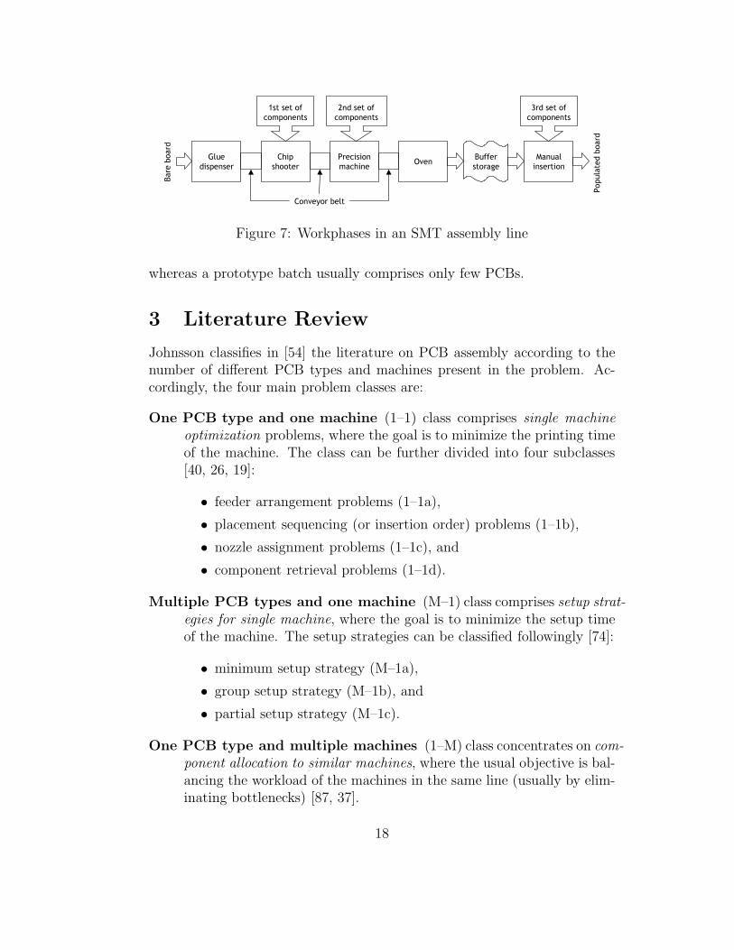
Some machines require that the component tape is preprocessed on anothermachine [56]. The surface mount onsertion is usually preceded by a gluedispenser and succeeded by an oven which hardens the adhesive and fixatesthe components, see Figure 7 [99] (similar lines are described also in [29, 44,117]). Typically, the production also includes inspection and testing phases.
The PCBs are transferred from one phase to another either manually(e.g., in magazines which can hold 10–100 PCBs) or with a conveyor belt.The conveyor-linked machines are usually referred as being coupled, and asystem with a batch transfer as uncoupled. Because the change of boardtype causes a setup, boards of the same type are collected in a batch, inwhich they are operated successively. The batch size can vary considerably:A mass-product PCB may remain in active production for several months,
17
�������������
���������
���������������
�����������������
������������
����� ����
��� ��� ���������
��� ��� ���������
�� ��� ���������
���� ��
��
���
����� �
���
Figure 7: Workphases in an SMT assembly line
whereas a prototype batch usually comprises only few PCBs.
3 Literature Review
Johnsson classifies in [54] the literature on PCB assembly according to thenumber of different PCB types and machines present in the problem. Ac-cordingly, the four main problem classes are:
One PCB type and one machine (1–1) class comprises single machineoptimization problems, where the goal is to minimize the printing timeof the machine. The class can be further divided into four subclasses[40, 26, 19]:
• feeder arrangement problems (1–1a),
• placement sequencing (or insertion order) problems (1–1b),
• nozzle assignment problems (1–1c), and
• component retrieval problems (1–1d).
Multiple PCB types and one machine (M–1) class comprises setup strat-egies for single machine, where the goal is to minimize the setup timeof the machine. The setup strategies can be classified followingly [74]:
• minimum setup strategy (M–1a),
• group setup strategy (M–1b), and
• partial setup strategy (M–1c).
One PCB type and multiple machines (1–M) class concentrates on com-ponent allocation to similar machines, where the usual objective is bal-ancing the workload of the machines in the same line (usually by elim-inating bottlenecks) [87, 37].
18

Multiple PCB types and multiple machines (M–M) class or schedul-ing problems usually concentrate on
• allocating jobs to lines (M–Ma) which includes routing, lot sizingand workload balancing between lines, and
• line sequencing (M–Mb).
Other classification schemes have been presented by many authors. Cramaet al. [26] associate a production plan with the following issues:
1. partition the set of board types into families which are to be assignedto different lines of placement machines;
2. for each board type, determine a partition of the set of componentlocations on this board (i.e., decide which locations are going to beserved by which machine);
3. for each machine, determine a feeder rack assignment (i.e., an assign-ment of feeders to position in the feeder rack);
4. for each pair consisting of a machine and a board type, solve a compo-nent placement sequence (i.e., an order in which components are placedat the locations on the board by the machine); and
5. for each pair consisting of a machine and a board type, make a compo-nent retrieval plan (i.e., decide for each component from which feederit is to retrieved).
Cases 3, 4 and 5 correspond to problem classes (1–1a), (1–1b) and (1–1d),case 1 is a job allocation problem (M–Ma), and case 2 is a component allo-cation problem (1–M).
Foulds and Hamacher [40] list the problems associated to PCB assembly:
1. the allocation of component types to machines,
2. the allocation of component types to feeder location at each machine,and
3. the pick and place sequence.
Here, case 1 corresponds to class (1–M), and cases 2 and 3 classes (1–1a) and(1–1b).
Feldman and Feuerstein present in [37] a hierarchical four-level optimiza-tion strategy to reduce changeover, setup and processing times based on thehierarchy of the assembly task:
19

1. job allocation and job clustering for each assembly line,
2. line balancing,
3. optimization of the feeder configuration, and
4. optimization of the insertion sequence.
In this scheme, cases 3 and 4 correspond to problem classes (1–1a) and (1–1b) respectively, case 2 is equal to problem class (1–M), and case 1 is equalto problem class (M–M).
McGinnis et al. [87] recognize three levels of decisions:
1. selection of machine groups and part families and assignment of familiesto groups,
2. allocation of components to machines when a group has more than onemachine, and
3. arrangement of component feeders and sequencing of placement oper-ations for each machine and PCB.
Here the levels correspond to problem classes (M–M), (1–M) and (1–1ab),respectively.
In this work we adopt the classification of setup management strategies(M–1) proposed by Leon and Peters [74]—with the exception that in ourscheme the unique setup strategy corresponds to single machine optimization(1–1):
• Unique setups consider one board at a time and specify the component–feeder assignment and the placement sequence such that the placementtime is minimized. This is a common strategy when dealing with asingle product and a single machine in a high-volume production envi-ronment.
• Group setups form families of similar parts such that setups are incurredonly between families.
• Minimum setup strategy attempts to sequence boards and determinecomponent–feeder assignments to minimize the total changeover time.
• Partial setups are characterized by partial removal of components fromthe machine when changing over from one product type to the next.
20

Another classification of setup strategies is given by McGinnis et al. [87] andAmmons et al. [8]:
1. Single setup strategy: Configure a group of machines to produce afamily of board types using a single setup which is sufficient for theentire family. There are two possible options for achieving this:
(a) Unique setup strategy : A single setup strategy applies to a familywhich contains only one product type (i.e., mass production).
(b) Family setup strategy : Several product types are in the same fam-ily. There is usually a tradeoff which must be explicitly examined;the family setup eliminates the need for machine setups betweenboard types at the price of potentially increasing the assemblytime for each individual board type in the family.
2. Multisetup strategy: Because a limited component staging capacity onthe placement machines prohibits the use of the single setup strategy,some additional setups must be performed within a family. In thisscenario, the objectives generally include the minimization of the pro-duction time consumed by setups along with the minimization of WIPlevels. There are two possible multisetup strategies:
(a) Decompose and sequence (DAS): Break the family into smaller setsof PCB types (possibly of size one), then sequence the subsets soas to minimize the incremental setups between the subsets. Thisstrategy requires some additional WIP at the risk of potentiallyhaving to remove a component type to process one subset of PCBsand then having to restage it for a later subset.
(b) Partition and repeat (PAR): Partition the required componentsinto subset such that the machine group has enough staging ca-pacity for each subset. Populate PCBs with components by config-uring the machines with each subset of component types in turn.This approach requires the accumulation of a batch of partiallypopulated PCBs but it includes relatively few setups.
In this scheme, the unique, family and DAS setup strategies correspondclasses (1–1), (M–1b) and (M–1a), respectively. The PAR setup strategy(see also [82, 31]) is a special case of (M–1b), where the boards in the groupare loaded several times to the same machine but with different componentsetup. Maimon and Shtub [82] classify four problem types according to howmany times (one or many) each component type and job (PCB) is loaded: In
21

type 1 each PCB and each component is loaded only once, type 2 constraintseach component to be loaded only once, type 3 constraints each PCB to beloaded only once, and in type 4 there are no limitations.
In the remainder of this section, we try to give a condensed presentationof the research done so far. We review the literature according to Johnsson’sclassification [54]: single machine optimization in Section 3.1, setup strategiesfor a single machine in Section 3.2, component allocation to similar machinesin Section 3.3, and miscellaneous scheduling problems in Section 3.4.
3.1 Single Machine Optimization (1–1)
Although we can recognize four distinct subproblems (feeder arrangement,placement sequencing, nozzle assignment and component retrieval) in singlemachine optimization, they are strongly intertwined and, therefore, usuallynot solved altogether independently. For example, an optimal placementsequence does not guarantee optimal printing time if the feeder assignment isneglected (and vice versa). Another aspect of the problem is the wide varietyof different machine environments considered in the literature. Most of thework have been based on (variants of) pick-and-place machines, but latelythe trend has shifted towards rotary turret machines as they have becomemore popular in industry. Also, manual and semi-automated operations areconsidered by some authors.
Ball and Magazine [12] study the problem of determining the compo-nent insertion sequence and feeder arrangement for a pick-and-place ma-chine. They regard the former problem as a special traveling salesman prob-lem (TSP). The authors model TSP as a stacker crane or rural postmanproblem, and present a heuristic algorithm for solving it. The metrics usedin the formulation affects the solution: If the placement head moves only inone orthogonal direction at a time, the Manhattan metric is used for mea-suring the length of the movements and one can find an optimal solution inpolynomial time. If the head can move in the x- and y-directions simulta-neously, Chebyshev metric can be applied for the distance calculations butthe solutions are then suboptimal. However, the authors prove that in thelatter case the maximum error of their solution is bounded. The feeder ar-rangement problem can be structured as the classical assignment problemwhen considered separately of the insertion sequencing. Although there areefficient algorithms for solving the problem, in this case the cost of assign-ing a component to a feeder location cannot be expressed as a simple costcoefficient, and, therefore, they cannot obtain optimal solutions.
Leipala and Nevalainen [72] recognize the insertion sequence and feederassignment problems in the single machine problem, and solve them sepa-
22

rately. The optimal insertion sequence for a fixed feeder setup can be ob-tained by considering the problem as a three-dimensional asymmetric trav-eling salesman problem. The optimal assignment of the components to thefeeders for a fixed insertion sequence can be formulated as a quadratic assign-ment problem. The overall problem can then be solved heuristically, whichbrings suboptimal but, in practice, satisfactory solutions.
Chang and Young [23] introduce a hypothetical machine design for simul-taneous mounting. The machine comprises one or more robots or a robotizedpick-and-place head, a component supply device (movable or fixed), and anassembly holding device (movable or fixed). To optimize the printing, the al-gorithm should determine stop positions for a PCB, the components printedat each stop position and the placement of components in the delivery head.The authors present a mixed-integer programming model of the problem anda branch-and-bound based greedy heuristic algorithm for solving it.
Leu and Ji [75] recognize three basic machine types—insertion, pick-and-place, and rotary turret—and discuss methods for solving the componentinsertion sequence in each of these. In an insertion machine, where a sep-arate machine (a sequencer) produces an input tape for components, theproblem is considered to be a TSP. In a pick-and-place machine with a mov-ing head, a fixed table and fixed feeders, the problem can be model as a ruralpostman, linear assignment or quadratic assignment problem. In a rotaryturret machine, the authors model the problem as a TSP and use a geneticalgorithm (GA) for solving it.
Supinski et al. [105] discuss the planning of the printing order and thegeneration of the robot code on a single machine. These tasks comprise threestages: CAD data importation, PCB assembly planning, and code genera-tion. In the second stage, the authors consider three separate workphases:In adhesive deposition the authors model the problem as a TSP and use thearc-opt or 3-opt method for solving it. In solder deposition, a two-step pro-cedure first clusters the solder pads and then applies a TSP formulation toeach individual cluster. In component insertion, the objective is to minimizethe number of components to be manually inserted on the board.
Zhou and Leu [119] describe a Petri net model for solving feeder assign-ment, printing order and tool assignment on a single machine. The authorspresent an ordinary (or non-timed) Petri net model for analyzing the sys-tem behavior (e.g., deadlock-freeness, buffer boundedness, reversibility andconflict-freeness), and a temporal Petri net model for evaluating the systemperformance (e.g., productivity and machine utilization).
Foulds and Hamacher [40] present methods for identifying optimal binlocations, which surround the worktable on all four sides, and for determininga component insertion sequence for the board. The authors model the former
23

problem as a single-facility location problem, and the latter problem as aTSP.
Zijm and van Harten [120] discuss a hierarchical decomposition for a mod-ular component placement system, which comprises several identical succes-sive insertion machines. To minimize the cycle time of a batch of PCBs, thefollowing problems must be solved: Firstly, determine the number of feedersfor each component type, and if more than one feeder contains the samecomponent, specify the board locations which are delivered from each feeder(solved with a greedy heuristic). Secondly, allocate feeders to the insertionmachines (solved with a local search heuristic). Thirdly, assign the feedersto the feeder positions of a machine (solved with the standard Hungarianmethod). Finally, specify a placement sequence for a given feeder assign-ment (solved with the 2-opt heuristic). If a solution on a higher level leadsto infeasible or inferior solutions on a lower lever, a feedback loop allows theprogram to change the higher-level solution, and thus avoid the problem.
Wang [112] compares three layout design methods for a dynamic pick-and-place machine with a mobile worktable and magazine, and a single place-ment head. The layouts include one-magazine-and-one-board (1M1B), one-magazine-and-two-boards (1M2B), and two-magazines-and-one-board (2M1B).Wang et al. [113] solve the placement sequence and feeder arrangement fora machine where the board and feeder carriages move on x-direction andthe head on y-direction. First, the insertions are sorted according to theirx-coordinate on the board, and the sorted list determines the placementsequence. By using this sequence, a matrix of the component exchange fre-quency (which describes how often a component pair is subsequent is thesequence) is built, and the problem is then modeled as a TSP and solvedaccordingly.
Sanchez and Priest [95] present a method based on artificial intelligenceand an expert system with sequencing decision rules for semi-automatic as-sembly. The approach divides the task into four phases: Firstly, designcriteria which simplify operators insertion routines are chosen. Secondly, theinsertion rules are prioritized (e.g., insert small components before large ones,insert all component of the same type successively, insert components in asequence which minimizes the movements of the machine bed). Thirdly,the components are grouped into insertion sequence classes. Lastly, theboard movements are modeled as a TSP and solved with the nearest neigh-bor heuristic. Khoo and Ng [63] discuss a similar problem formulation butapply a genetic algorithm for solving the placement sequence. They comparethe results to Sanchez and Priest and observe an improvement in the totaldistance travelled by the machine bed.
Johnsson et al. [55] discuss designing an efficient and easy-to-learn se-
24

quencing for manual installation of components. Favorable sequences canbe characterized by several nonstrict rules (e.g., use both hands equally inthe insertion, proceed from top to bottom and from the edges to the center,and take the closest next part). The authors present three different sequenc-ing methods: line sweeping, traveling salesman clustering, and weighted 3-matching.
Sadiq et al. [94] present a method for arranging feeders in a SMT machinein a low-volume, high-mix environment. First, the slots are assigned byusing a heuristic rule, and, after that, the slot rearrangement process tries tolocate the components so that they are adjacent in the insertion sequence.The goal is to assign the components inside a contiguous group to makethe components required by a PCB adjacent, and thus save feeder carriagemovements.
J. Ahmadi and coworkers have studied dual delivery pick-and-place ma-chine in several papers: J. Ahmadi et al. present in [2] an emulator forstudying the effect of different printing process parameters. The overall sys-tem is modelled by subproblems: Component allocation problem tries tomaximize the number of board completions attainable by a single allocationof components. Partitioning problem minimizes the idle time caused by im-balance in the use of the manipulators and nozzle changes. The authors givea detailed discussion of these problems in [3], where they present mathemati-cal formulations and solve them with a mixed integer programming package.R. Ahmadi and Kouvelis [4] concentrate on the same machine and presentmethods for solving single product staging problem (SPSP) and multiprod-uct staging problem (MPSP). SPSP involves the assignment of the requiredcomponent feeders for the specific board type to the two carriers, while simul-taneously assigning the required tools (for dispensing each component type)to the tool magazines by observing capacity constraints. The objective is tominimize the total time to assembly the PCB. The authors give an integerprogramming formulation as well as present a Lagrangian relaxation basedbranch-and-bound algorithm for SPSP. In MPSP, the objective is to mini-mize the total time to assemble a given set of multiple PCB types. Finally,J. Ahmadi et al. [1] study the feeder assignment problem by formulating itas a reel positioning problem (RPP), where the goal is to minimize the direc-tion changes and the sum of movements of the feeder carrier. In addition tothe mathematical formulation, the authors give a heuristic algorithm basedon solving the shortest path in a layered network. A two-manipulator ma-chine is also considered by Hernandez and Leon [46], who discuss interferenceavoidance of the manipulators working on the same area.
Crama et al. [27] and van Laarhoven and Zijm [111] present hierarchicaldecomposition schemes for a line of 3-headed pick-and-place machines. In
25

both papers the goal is to minimize the processing time of the bottleneckmachine. Crama et al. identify six subproblems: (1) determining how manycomponents each machine must mount and with what equipment, (2) assign-ing feeder types to machines, (3) determining what components each headmust mount, (4) clustering the locations into subsets of three, (5) determiningthe sequence of pick-and-place operations, and (6) assigning feeders. Thesesubproblems are then solved by using simple heuristic algorithms. Corre-spondingly, van Laarhoven’s and Zijm’s problem hierarchy has five steps—determining equipment for the heads on each machine, assigning componentsto the machines, assigning feeders, clustering components for pick-and-placeoperations, and sequencing the cluster and component within each cluster—which are mainly solved with simulated annealing.
Optimizing feeder arrangement and insertion sequence of a rotary turretmachine is discussed by several authors. Bard et al. [13] model the place-ment sequence of such a machine as a TSP and solve it with nearest neighborheuristic. Moreover, they formulate the feeder assignment and component re-trieval problems as a quadratic integer program and solve it with Lagrangianrelaxation. Yeo et al. [117] present a rule-based system, which employs sim-ple heuristics: Feeders are assigned according to a one-pitch incrementalheuristic. The placement sequence is modeled as a TSP and solved with thenearest neighbor method. Crama et al. [26] use hierarchical decomposition,and solve the feeder assignment, the component placement sequence and thecomponent retrieval plan with local search heuristics. The overall objectiveis to minimize the sum of makespans on the bottleneck machine on a singleproduction line. Altinkemer et al. [7] present an integrated model and heuris-tic for assigning the feeders and sequencing the placement operations. First,the delivery problem is solved for each component type at every possiblefeeder location. A feasible solution can be used as the cost of assigning thecomponent type to the feeder location in question. The assignment problemcan then be solved by using these costs.
Crama et al. [25] discuss the component retrieval problem (CRP) in detail.In CRP, the placement sequence of components on the board, and the assign-ment of component types to (possibly multiple) feeder slots are given. Theproblem is then to decide from which feeder slot each component should re-trieved. Naturally, this problem emerges only if at least one component typeis duplicated in the feeders. The authors describe a PERT/CPM networkmodel of CRP, and present a polynomial algorithm for solving the problem.
Educational and research topics have been considered by Bodner andcoworkers and Feldman and coworkers. In [19] and [18] Bodner et al. presenta virtual machine model, in which three mechanisms—component feeder,board locator, and placement mechanism—interact. The authors describe
26

two approaches of studying process planning and equipment configuration:prescriptive models which emphasize the determination of a near-optimal so-lution to the given problem, and descriptive models which emphasize theperformance evaluation of a specified set of solutions to the problem. In thisview, a virtual prototype is a descriptive model that allows one to assess per-formance of a machine or system off-line. Feldman et al. [38, 37] describe asimilar approach for modeling the whole production line. It allows to demon-strate the production starting from planning and ending to the diagnosis ofsimple assembly processes.
3.2 Setup Strategy for Single Machine (M–1)
Coble and Bohn [24] recognize two approaches to reduce setup times: (1)reduce the time to set up a feeder, and (2) reduce the number of feeders tobe set up. The authors argue that most of the research have concentratedon the latter approach and ignored the former. Consequently, the authorspresent a two-part approach for reducing the time to set up a feeder: First,processes are re-engineered using SMED (single minute exchange of dies)concepts (which were originally developed for metal fabrication). After that,a factory information system with wireless computers and barcode scannersare used both to reduce the setup time and to increase the setup accuracy.There are two kinds of setup operations: offline setup, which can be donewhile the machine working, and online setup, which can be done only whenthe machine is shut down. The SMED approach begins with recognizinginternal and external setup tasks and assigning the external tasks to be doneoffline. Next, as many internal operations as possible are converted to exter-nal ones to further reduce online setup. Finally, both internal and externaloperations are streamlined. The authors also discuss other procedures in-cluding hot swapping (fill one feeder carrier while the other is being used),a barcode system for feeders, a computer system for locating parts, addingmore operator to the lines, and operator training.
In the remainder of this subsection, we concentrate on the second ap-proach (i.e., reducing the number of feeders to be set up).
Minimum setup strategy (M–1a) Minimum setup strategy attemptsto sequence the PCBs and determine feeder assignments to minimize thetotal component setup time. The idea is to perform only the feeder changesrequired to assemble the next PCB batch. Here we aim at avoiding additionalfeeder changes or reorganization, which would reduce the placement time.In general, similar product types are produced in sequence so that littlechangeover time incurs.
27

Lofgren and McGinnis [78] point out two key decisions: We must solvein what sequence the PCB batches are to be processed by the machine, andwhat component types should be staged on the machine for each PCB type.The authors present a sequencing algorithm (SEQ) based on labeling concept,in which the PCBs are first sequenced and after that a setup is determinedfor each PCB. The heuristic determines myopically the “best” componenttypes to remove and to add whenever the existing setup is not sufficient.
Barnea and Sipper [14] consider a case of one machine and recognize twosubproblems: sequence and mix. They present a mathematical model of theproblem and use a heuristic approach based on the keep tool needed soonest(KTNS) policy introduced by Tang and Denardo in [106]. In each iteration,the algorithm generates a new partial job sequence by using a sequencingalgorithm—which decides the next job to be added in the sequence—andmix algorithm—which updates the component mix with KTNS.
Jain et al. [52] present a four-stage method for optimizing the setup:Firstly, a greedy heuristic maximizing the component similarity of the jobs isused to determine an initial processing sequence. Secondly, the componentsare assigned to feeders according to KTNS policy. Thirdly, the jobs arerearranged in the sequence by applying 2-opt heuristic and KTNS. Finally,because the production is a continuous process, at the end of the sequencethe frequently used components are preserved for the next production period(i.e., the approach gives heed to the rolling horizon framework).
Gunther et al. [44] present a typical SMT production line and apply theminimum setup strategy approach, in which the PCBs are sequenced so thateach subsequent PCB has the maximum number of components commonwith its predecessor. The authors discern three different subproblems—jobsequencing, component setup and feeder assignment—and solve each of themwith heuristic algorithms.
Narendran and coworkers have studied a heuristic approach which startsfrom an initial setup (a seed) and sequences the PCBs by looking for the sim-ilarities between the current setup and the PCBs remaining to be sequenced.In [93], Rajkumar and Narendran form the sequence by considering the over-all component requirement of the PCB and the number of extra componentsrequired in the setup. In [68], Kumar and Narendran add a third constraint,slack time, and observe better result in comparison to dispatching rules (e.g.,earliest duedate, shortest processing time and least remaining slack) usednormally for single machine scheduling with duedates.
Dillon et al. [33] discuss minimizing the setup time by sequencing PCBs ona surface mount technology production line. The authors present four variantof a greedy heuristic which aims at maximizing iteratively the componentcommonality whenever the PCB type changes. This is realized by using a
28

component communality matrix from which board pairs with a high numberof common components can be identified.
Group setup strategy (M–1b) In the group setup strategy the feederassignment is determined for a group or a family of similar PCBs. Anyboard in this group can be produced without changing the component setup,which is only required when switching from one group to another. Becausethe placement time for a specific board is, in general, larger than in uniquesetup strategy, some efficiency can be potentially lost. However, this is com-pensated by less frequent setup operations, which compensates the lossesin machine speed especially in high-mix, low-volume production. There arevariations of the group setup strategy, where a certain set of common or stan-dard components are left on the machine, while the rest of the components(residual or custom) are added or removed as required for a particular board.
Carmon et al. [22] describe a group setup (GSU) method for a high-mixlow-volume production environment. The products are divided into groups,each of which is produced in two stages: Set up common components andinsert them to the PCBs of the whole group, and set up the residual com-ponents and insert them on each PCB separately. In [83], the same au-thors compare GSU to sequence dependent scheduling (SDS) on three per-formance measures—line throughput, average WIP level and implementationcomplexity—and conclude that in general SDS performs better on the lasttwo areas. Practical analysis of these two methods appear also in [29, 69].
Maimon and Shtub [82] present a mixed-integer programming formulationand a heuristic method for grouping a set of PCBs to minimize the totalsetup time. A user-defined parameter indicates whether multiple loadingof PCBs and components is allowed (cf. partition and repeat strategy in[87]). This approach is developed further in [31] by Daskin et al. Theirgoal is to minimize the total component and PCB loading costs subject to acapacity constraint. The authors present a mathematical formulation for thePCB-grouping problem, show that the problem is NP-complete, and give abranch-and-bound based heuristic algorithm for solving it.
Shtub and Maimon [98] establish that grouping PCBs is an extension ofthe set-covering problem and present a general heuristic approach based oncluster analysis and similarity measures (e.g., Jaccard’s similarity coefficient)which are traditionally found in the literature concerning group technology.Here the goal is to minimize the total production time, but since insertiontimes are assumed to be constant, the objective reduces to minimizing thetotal setup time of the groups.
Hashiba and Chang [45] study a single machine case when the objective
29

is to minimize the number of setups. They decompose the setup probleminto three subproblems—grouping PCB types, sequencing the groups, andassigning components for jobs—and apply heuristic algorithms to each ofthem individually. Furthermore, the authors experiment with a simulatedannealing method and observe that it gives better solutions than the heuristicdecomposition approach.
Luzzatto and Perona [81] present a heuristic method for grouping PCBsto minimize the setup size. Although the authors consider a production lineconsisting of several workphases, their model enables the solution for eachworkphase to be obtained separately from the others.
Bhaskar and Narendran [17] apply graph theory for grouping PCBs. ThePCBs are modeled as nodes and their similarities as weighted arcs betweenthe nodes. After that, a maximum spanning tree is constructed for identifyingthe PCB groups.
Xu et al. [116] form PCB groups and divide the feeder slots into three“feeder bays”: fixed, semi-fixed, and configurable (cf. [8, 99]). The fixedfeeder bay comprise the most frequently used components and it remainsconstant throughout the production, whereas the semi-fixed feeder bay ischanged whenever the group changes and the configurable feeder bay when-ever the board type changes.
Smed et al. [99] give an integer programming formulation of the job group-ing problem (cf. [28]), and compare several heuristic algorithms based ongreedy, clustering and repair-based local search methods. Johtela et al. [62]expand the problem to account multiple and possibly conflicting groupingcriteria—such as different substrate widths, adhesive types, and productionpriorities—by modeling them as fuzzy sets.
Ohno et al. [89] group PCBs to minimize the sum of the assembly andsetup times. The authors present a multi-type PCB assembly (MPCBA)optimization problem, which is divided into three subproblems: insertionsequence problem (ISP), reel position problem (RPP), and optimal assemblymode problem (OAMP). ISP is modeled as a TSP for fixed reel positions (i.e.,feeder assignment), and solved with a 2-opt heuristic. RPP is viewed as anassignment problem, where the cost is the sum of weighted tour costs of theTSPs for the group, and it is solved with an evolution strategy. Evolutionstrategy is also applied to OAMP, which is modeled as a set partitioningproblem with TSP type constraints.
In addition to placement machines, the group setup strategy has beenproposed for sequencer problems: Fathi and Taheri [36] present a heuristicalgorithm to group products for minimizing the setup of a sequencer for anaxial placement machine. Sule [104] applies group technology and devel-ops a heuristic method to minimize the changeover cost and to balance the
30

workload between sequencers.
Partial setup strategy (M–1c) Partial setup strategy specifies that onlya subset of the feeders on a machine are changed when switching from oneproduct to the next. Because the goal is to minimize makespan, the partialsetup strategy resides between the unique setup strategy (where only theplacement time for each individual PCB is minimized) and the minimumsetup strategy (where only the changeover time of each PCB is minimized).
In [73], Leon and Peters present a heuristic for composing partial setupand compare its solutions to the corresponding unique, minimum and groupsetups. Obviously, unique setup dominates when batch sizes are large (suchas in mass production). The group setup strategy dominates the minimumsetup strategy, because it considers all the PCBs. The partial setup strategyperforms well under all scenarios. In [74], the same authors confer similar re-sults from a broader set of experiments. In [90], Peters and Subramanian an-alyze four partial setup strategies—unique setup, sequence dependent setup,tradeoff dependent setup, and minimum setup—and conclude that no singlefixed strategy dominates in all scenarios.
3.3 Component Allocation to Similar Machines (1–M)
Only few papers considering the case of similar (sequential) machines in thesame production line have been put forth. Here, the most eminent criterionis workload balancing so that the bottlenecks of the line are eliminated.
Lofgren and McGinnis [79] present a soft configuration decision, which hasan impact on two key criteria: workload on each machine (i.e., balancing),and material handling (i.e., machine visits). The soft configuration problemspecifies the attributes which are available on each machine and, therefore,it determines the set of operations which could be performed. The authorsconsider three operating policies: dynamic (where tools are added or removedso that the required operation can be done in one machine without routingit to another), static (which specifies configuration for a finite productionhorizon and routes jobs to appropriate machines) and pseudo-dynamic (wheresome attributes are static and the rest dynamic). The authors give heuristicalgorithms for static and dynamic operating policy, where the objective is tomaximize machine utilization and minimize material flow transactions.
Ben-Arieh and Dror [15] consider assigning components in a case of twoinsertion machines, so that all boards in a production plan can be produced,and the output rate is maximized. They give a mathematical formulation ofthe problem and solve it with a heuristic algorithm.
31

Askin et al. [10] discuss a surface mount technology plant with multi-ple identical machines. They present a four-stage approach for grouping theboards and allocating the components to the machines: First, the boardsare grouped into production families. Next, for each family, the componenttypes are allocated to the machines. After that, the families are divided intoboard groups with similar processing times. Finally, the groups are sched-uled. The objective is to minimize the makespan for assembling a batch ofboards and to reduce the mean flowtime. The authors present and comparethree heuristic methods—component-assignment/workload balancing algo-rithm (CAWB), workload balancing algorithm with shortest total processingtime (WBASPT), and natural board subfamily algorithm (NBSA)—and con-clude that CAWB and WBASPT outperform NBSA.
Watkins and Cochran [114] consider a line of similar insertion machines,and propose a heuristic method for rebalancing the workload by movingcomponents from the bottleneck machine to other machines. However, eachmove is associated with a cost, and the method finishes when the cost of amove outweighs savings.
McGinnis et al. [87] give a mathematical model for component allocationfor both coupled and uncoupled machines. Ammons et al. [8] continue thework by considering component allocation to two or more placement ma-chines, when the objective is to balance a combination of the assembly timeand the machine setup time. When machines are coupled, the workload bal-ancing reduces to maximizing the throughput of the bottleneck machine online. The authors approach the component allocation problem by developingtwo heuristic methods based on list processing and branch-and-bound tech-nique. Furthermore, they give an integer programming formulation, whichtries to minimize the maximum combined PCB assembly and machine setuptime for each PCB over all machines.
Brandeau and coworkers consider assigning components to machines in anassembly plant with different types of workphases (automatic, semi-automaticand manual). The goal is to minimize the total setup and processing cost forassembling all boards. In [21], Brandeau and Billington present two heuristicalgorithms: stingy component (which tries to avoid assigning less frequentlyused components to the automatic workphase) and greedy board (which triesto assign a whole board to a single workphase instead of splitting it). Aftera set of tests, the authors conclude greedy board to be a better method ofthe two, because the setup cost are high relative to the insertion costs. In[48], Hillier and Brandeau extend the same problem by presenting a newmathematical model and an improved heuristic based on branch-and-boundtechnique. In [47], the same authors further expand the mathematical modelby introducing a workload balancing criterion and introducing CMWB (cost-
32

minimizing, workload balancing) heuristic.
3.4 Scheduling (M–M)
Production can be analyzed on different levels: On the long-term level, theanalysis uses general presumptions and a simplified mathematical model,whereas a short-term analysis, as a rule, is based on simulation. On thehighest level of production planning the problems are general, and they can-not be solved without the support and feedback from the lower levels ofplanning.
Gershwin et al. [41] present a decomposition approach for determiningdispatch dates for an FMS, in which the machines are unreliable to satisfythe production requirements. The authors consider, when the parts shouldbe dispatched to satisfy weekly production requirements. The problem issolved in two stages: First, the instantaneous production rates are solved byconsidering a high level continuous dynamic programming problem. Afterthat, a combinatorial algorithm determines the dispatch times at the lowerlevel.
Johri [58] considers scheduling from a practical point of view, and presentsa technique for sequencing PCB batches. The presented method begins witha realistic scenario, in which the production has been active for some time,and new jobs are inserted to existing production sequence. At each insertion,the goal is to minimize the imbalance of the machine workloads and to ensurethat the duedates are not violated. In addition, the number of setups isminimized, if possible. The method works as follows: First, it determinesdesirable production rate for each workstation. After that, the inserted jobsare grouped according to their duedates. Next, the method determines thegroup with the least slack time, and calculates penalties for each job in thatgroup. Finally, the job with the minimum penalty (other heuristic rules arealso possible) is inserted into the sequence. When the situation is updated,iteration continues until all jobs are sequenced.
Johri [59] discusses the design of a production line with respect to thecapacity constraints and flowtime minimization. The intention is to deter-mine the amount of different machine types, buffer sizes, lot sizes and theloading sequence, when the products, processing times on each machine typeand the machine downtimes are given. The number of machines requiredin a workphase are obtained from a simple equation, as well as the averageflowtime and capacity of the line. The average in-process inventory can beacquired by using Little’s law (i.e., it equals the average flowtime multipliedby the production rate), and by minimizing this value the desired flowtimecan be attained.
33

Lofgren et al. [80] study the station routing problem (SRP), where thesequence of the component assembly operations is determined so that it min-imizes the number of workstation visits. The authors use a graph theoreticapproach, in which a precedence graph is partitioned according to worksta-tions and used to determine a workstation sequence which has the minimumcardinality. SRP is shown to be NP-hard, and therefore the authors testand analyze several different heuristics for the problem.
Klegka and Driels [66, 34] put forth a simplified model for measuring costsin long-term production planning. It yields intuitive results when used forcomparing different production line layouts. The authors observe that themost economical assembly system is obtained when enough manual assemblypersonnel are provided to reduce the maximum station time to that of theslowest assembly machine. In batch production, even small lot sizes areeconomically justified, since the effect of frequent changes is less significantthan might be expected.
Ben-Arieh and Maimon [16] consider a case of two different sequentialmachines which use the same sequence (i.e., a permutation schedule). Theobjective is to minimize the mean flowtime, and the authors solve the problemby using simulated annealing approach.
R. Ahmadi and Wurgaft [6] consider a mid-variety, mid-volume produc-tion environment with synchronized flow manufacturing, where the materialsmove smoothly and continuously from one operation to the next. The objec-tive is to maximize the throughput rate. Each time there is a major changein the product mix and demand, there are three problems to be solved: (1)how many stations should be created, (2) how many machines each stationshould have (i.e., machine allocation problem), and (3) which operations areperformed by which station (i.e., staging problem). To balance the totalworkload the maximum workload of a station should be minimized. The au-thors give a mathematical formulation of the problem as a quadratic integerprogram.
Dagnino [30] presents a system which combines product design, assem-bly planning, line balancing and the generation of the shop floor drawings.The main problem is general process planning, which involves deciding howto use the capabilities of the shop floor to manufacture a given product. InPCB assembly, the author recognizes the following stages: (1) identifying thecomponents to be printed on a PCB, (2) determining the required assemblyoperations, (3) assigning resources to the assembly operations, (4) sequenc-ing the assembly operations, (5) line balancing, and (6) developing shop aids.The major issue is the hierarchy of these decisions and dependencies betweenthe stages: When a decision is made on a higher level, the lower-level charac-teristics are generalized. However, at some point, the technical details cannot
34

be omitted, and the system must be able, for example, to calculate accurateoperation times for each individual machine.
Khoshnevis et al. [64] also recognize the potential of a general schedulingsystem, and present an integrated system for assembly planning and schedulegeneration. In assembly planning, the system prepares a detailed sequenceof operations to transform a set of disjoint components into a final product.In scheduling, the system assigns manufacturing resources to the operationsindicated in the assembly plan in such a way that some relevant criteria (e.g.,duedates) are met. The main idea of the solution algorithm is to assign jobsto machines on the basis of the availability of machines (or of a quantifyingfactor which is calculated with heuristic rules) and the requirements of theunfinished jobs.
Klincewicz and Rajan [67] consider the component grouping problem inan environment of multiple board types and multiple workcells. The problemis to decide how should the components be assigned (i.e., partitioned) amongthe workcells so that the number of machine visits is minimized and theworkload is balanced. The authors give an integer programming formulation,where minimizing the machine visits is modeled as an objective functionand the load balancing as a constraint (i.e., each workcell has a maximumallowable deviation from the average insertion volume). GRASP (greedyrandom adaptive search procedure) method (i.e., a local search replicatedmany times with different, randomly chosen starting points) is used to solvethe problem. The authors present two variants of the initial starting points:Component-based variant assigns a pair of components to the same workcellif a large number of the items to be produced use both components, whereascode-based variant looks at the larger volume board types and attempts topack the components belonging to a board type on as few new workcells aspossible. The initial solutions are then improved by moving components fromone workcell to another or by exchanging components between two workcells.
Dessouky et al. [32] convert the scheduling problem of flexible assemblylines to a flow line scheduling problem. This approach assumes that eachmachine processes the product at most once, the setup time depends only onthe machine type, processing time variability is negligible, and setup timesare small in comparison to batch processing times. The goal is to maximizethe throughput while keeping WIP at a minimal level without increasingthe resources of the assembly process. The batch sizes and the numberof each machine type are given in the problem formulation. The authorspresent a solution method comprising two phases: In the first phase, ma-chines are grouped into workstations which are visited by each product inthe same sequence. Thus, the problem is converted into a flow line configu-ration problem. Moreover, the task is to determine a permutation schedule,
35

which maintains the same sequence down the line in each workstation. In thesecond phase, the products are assigned to the first workstation (since thesubsequent workstations will have the same sequence) by using Campbell’sheuristic.
Feo et al. [39] also present an integrated decision support system, IN-SITES (integrated scheduling and throughput evaluation system), for schedul-ing, inventory and throughput evaluation. It provides the shop floor man-agers with the real-time information needed to make critical production plan-ning and control decisions. The user inputs the PCBs, duedates, quantities,WIP, and machine state. After that, the system computes the daily produc-tion quantities and generates MIS (management information system) reports.Because planning includes several conflicting objectives (e.g., duedates, work-load balancing, throughput maximization and waiting time reduction), thesystem offers a set of schedules, from which the user can select one for theproduction. The authors point out that instead of being constant, the loadtimes fluctuate with the job priorities, parts status, processing requirementsand customer demands. Variability of the processing capacity defers the workand delays the batches. The system assigns the lot sizes so that they dividethe demand evenly, and schedules the jobs according to the slack values.
Kim et al. [65] compare four sequencing algorithms, where the objectiveis to minimize the sum of tardinesses. NEH algorithm sequences the jobsaccording to a simple objective function (e.g., in increasing order of duedatesor in decreasing of total workload). ENS (extensive neighborhood search)method begins with a proper initial sequence and tries to improve it withswap operations. RBO (rolling block optimization) algorithm also beginswith an initial job sequence. After that, it resequences a block of sequentialjobs (i.e., window) trying to improve the local sequence while the rest ofthe jobs remain intact. The window gradually moves through the sequenceuntil it reaches the end. The fourth studied approach, tabu search, is basedon local search methods, where getting back to previously found solutions isprevented with a tabulist.
Johnsson et al. [57] introduce a generalized flexible flow line (GFFL)scheduling problem, where the products visit successive machine banks, andthe processing time is a function of the product and the machine type. Theauthors present a mathematical model of the problem and describe an in-teractive production scheduler, which can be used for analyzing schedulescreated either manually or by a heuristic algorithm.
Lin et al. [76] present a Bi-Level Scheduling System (BLISS), which inte-grates both product-level and board-level scheduling on a capacitated multi-ple flowline and strives to determine economical lot sizes and job sequences.Product level scheduling shifts a complete set of boards for a product so that
36

no WIP inventory is built up. Because this does not necessarily use the pro-duction capacity optimally, the schedule is then improved with a board-levelscheduling, which minimizes tardiness but may increase WIP. The authorsapproach the problem by applying general scheduling methods (e.g., Palmer’salgorithm, Gupta’s algorithm and CDS heuristic). From their experimentsthe authors conclude that the two-level approach suits well when duedatesare very tight or product demand is highly variable.
Nesbit [88] describes general requirements for constructing a computersystem for analyzing assembly processes. The possible benefits of such asystem include reduced machine setup times, increased quality of the finalproduct, and better throughput.
R. Ahmadi and Kouvelis [5] present a mathematical framework for de-signing and configuring the layout of electronics assembly lines. When themachines are tightly coupled due to small buffer space, throughput can be in-creased and WIP levels reduced by decreasing the setup times and balancingthe machine workload. Also, configuration can be based on the assumptionthat around 80 percent of the cumulative product demands are known tofollow a regular pattern. The authors analyze three design approaches: Inthe mini-line approach, PCBs are divided into families, and each family isproduced in a dedicated line. In the flexible flow line (FFL), there is only oneline and all the components required for the assembly of the various PCBsare concurrently present on the line. Thus, major line setups can be avoidedbut the machines are bound to be underutilized. In hybrid line approach,several PCB families are produced in the same mini-line. The authors for-mulate the electronics assembly line design problem (EDP), from which theydefine special cases for each of aforementioned approaches. From the com-putational experiments, the authors conclude that FFL dominates the otherdesign in terms of throughput performance but with increasing setup times,the mini-line provides higher throughput than the others. Moreover, theauthors discuss the suitability of the designs to different production environ-ments.
Balakrishnan and Vanderbeck [11] discuss a high-mix, low-volume pro-duction plant with several identical assembly lines. Each line includes achip-shooter which is the bottleneck the line. The aim is to group productsand assign the groups to different lines so that workload is balanced andthe setup times are minimized. Because these goals are contradictory, thepresented model tries to minimize the setup costs while keeping the work-load within prespecified limits. A partial setup (which should not be confusedwith the partial setup strategy of Leon and Peters [74]) comprises permanentand temporary components (i.e., a standard and custom setup [8]). The au-thors argue that this partial setup is a compromise between “complete” (i.e.,
37

unique) and “incremental” (i.e., minimum) setup, because it reduces setupoperations by exploiting component commonalities and is easier to handlethan incremental setups. The authors give an IP formulation of the problemand reformulate it as a capacitated set covering (CSC) model. CSC has twosubproblems: Production selection (PS) decides to which machine a productshould be assigned so that setup times are minimized and workload is bal-anced. Setup optimization (SO) decides which components are permanentand which temporary for a group of products on a single machine so thatsetup costs are minimized. PS is solved with list heuristics, local search andsimulated annealing. SO is solved with a combination of heuristics, lowerbounds and enumeration.
Lin and Tardif [77] consider multiple board types in a single line. Theline is set up once, and there are no setups between the boards. The problemis to partition the component types to the machines in the line so that allthe boards can be processed quickly and with a good workload balance. Theboard demands and machine breakdown occurrences are predicted with aprobability distribution. Moreover, it is assumed that there are no precedenceconstraints on the order of component placements, the placement time isconstant for all the components placed by a machine, and a new batch cannotbe processed until the current one is completed. Although heuristic methods(e.g., greedy and two-dimensional vector packing heuristic) often providesatisfactory results, they are not applicable here, because they do not considerdemand and capacity uncertainty. Therefore, the authors present a stochasticmixed-integer programming formulation for the problem, where the objectiveis to minimize the makespan for all the PCBs during a production cycle.
Spedding and Sun [103] describe a cost system which uses an activitybased costing (ABC) model. Since much of the significant costs in producingan item are not volume related, ABC should provide a better cost model.The idea is to develop a discrete event simulation (DES) model by observingthe actual production times of activities in a plant and then characterizingtheir statistical variation. Activities are classified into four general categoriesaccording to when they are performed: unit level (each time a unit is pro-duced), batch level (each time a batch is produced), product level (needed tosupport the manufacturing of a product), and facility level (needed to sus-tain the factory’s performance; e.g., rent, depreciation, and insurance). Theauthors apply ABC modeling in a simple SMT assembly line.
Simulation-based systems Simulation has been a widely used approachfor modeling PCB assembly plants. Almost all papers which compare schedul-ing algorithms use simulation for testing the methods. However, because the
38

focus in these papers is on developing actual optimization algorithms, the de-scription of the simulation model is usually terse, and testing and analyzingsettle for a modest set of test cases and bypass statistical tests.
Shevell et al. [97] present an early simulation system for analyzing a com-plex PCB manufacturing system. They also discuss the validation of thesystem and compare the results with real-world data. Taylor [107] also de-scribes a simulation tool for evaluating flexible control strategies.
Johtela et al. [61] describe a simulation tool for creating and analyzingschedules in a GFFL environment. The system simulates the productionfrom an initial situation to a given moment in the future. The input definesthe product batches, their allocation and sequence for each machine and theduedates. The output includes summaries of the production period includingthe lateness of the batches and machine workload charts. The user can recon-sider the allocation and sequencing of the batches and repeat the simulationand update operations to find a better balancing of the workload. Hayrinenet al. [50] describe several scheduling algorithms for GFFL problem, whichare implemented and integrated into the system.
Jackson and Johansson [51] present a discrete event simulator to supportdecentralized decision making. Production control benefits from that theworkers have a forecast of the coming workload in real time. The systemis directly linked to the information system of the company and it updatesthe state of the production process every ten minutes. Each machine has aforecast for six hours, which is shown on the screensaver on every PC in theshop floor. The simulation operates on both strategic level (development ofa new production system or improvement of a production system) and oper-ational level (estimates of capacity needed for a product mix, consequencesof WIP for a particular product mix, and consequences in delivery dates dueto a particular plan).
Estremadoyro et al. [35] describe a simulation tool, Electronics Manufac-turing Simulator (EMS), for modeling and analyzing assembly line layouts.The system uses simple specifications for forming a processing line, generatesalternative designs, approximates throughput, simulates the operation withdifferent parameters, and produces a set of output summaries for the givenlayout. The system comprise a line definer and static analyzer, which pro-duces station processing times (used in estimating the maximum throughputof each station) and line capacity.
Smed et al. [100] discuss the structure and operation of an interactivescheduling system for a high-mix low-volume SMT assembly line involvingmultiple criteria (e.g., different adhesive types, conveyor belt configurations,and priorities). The criteria are modeled with fuzzy sets, and the user canset weights for the importance of the criteria. Thus, the poor satisfaction
39

of some criterion can be compensated with other criteria. The user can alsomanipulate the schedule directly via a graphical user interface as well asemploy feeder and printing order optimizers selectively.
4 Commercial Software Systems
There are several software tools for production planning available in the mar-ket but relatively few of them are specialized to the PCB assembly. Generictools seldom suit for production planning in PCB manufacturing due to thespecial requirements associated with it: Firstly, the system must have knowl-edge about the machinery used in the production environment, its capabil-ities and limitations. Secondly, a production planning tool should have atight integration with the existing systems, such as CAD/CAM (computeraided design/manufacturing) or MRP (material resource planning) systems.Thirdly, in practice the usability of a system reduces drastically, if it doesnot produce NC-codes for the machines. Since PCB manufacturing facilitiesare usually highly automatized, the goal of a production planning system isnot to impose any further work to the personnel.
In this section we review briefly some of the most popular software sys-tems designed to support PCB assembly. The systems and their key featuresare listed in Table 1. We concentrate on the optimization features, albeitoptimization is rarely the primary task in these systems. The systems aremainly designed for automatizing the PCB design and manufacturing pro-cesses, such as joining bill of materials (BOM) files and CAD files togetherand generating NC-codes for machines. We have to point out, however, thatour experience with some of these system is limited, and, therefore, we arein some cases forced to resort to information gathered from the vendors’ webpages and brochures [60]. The possible errors, omissions and inaccuraciesare due to this fact. Moreover, the list of the machine vendors’ systems in-cludes only a few entries although almost all machine types in the markethave their own proprietary system. However, the current trend is that themachine vendors are starting to co-operate with the general system providers.
In Table 1 the systems are divided into two categories: tools providedby the machine vendors and tools provided by independent companies. Amachine vendor’s system usually supports only its own equipment and in-cludes a concise interface and some simple code optimization routines. Con-versely, since production plants may comprise multiple machines from differ-ent vendors, the independent systems aim at providing better support (e.g., acentralized component library, better CAD support, product transportationfrom one machine to another) for various machine types and makes. They
40

Vend
orPa
ckag
ePl
atfo
rm(s
)
Pick
&
Plac
e M
achi
nes
Rot
ary
Turre
t M
achi
nes
Thru
Hol
e M
achi
nes
Inpu
t fro
m
CAD
BOM
&
CAD
Jo
inin
gN
C-c
ode
Gen
erat
ion
Prin
ting
Ord
erFe
eder
sSe
tup
Line
Ba
lanc
ing
Sche
dulin
g
Dar
eba
Cor
pora
tion
cim
-SC
AND
OS,
Win
dow
s, U
nix
••
••
••
••
•
Mitr
on C
orpo
ratio
nC
IMBr
idge
’97
Win
dow
s•
••
••
••
••
••
Tecn
omat
ix-U
nica
m S
oftw
are
Inc.
Uni
Cam
Win
dow
s•
••
••
••
•
Fact
ory
Advi
sor
Win
dow
s•
••
Tecn
omat
ix T
echn
olog
ies
Ltd.
EXAL
INE
Win
dow
s, U
nix
••
••
••
••
Uni
soft
Cor
pora
tion
EZ-C
IM/E
Z-C
AMW
indo
ws
••
••
••
••
FABM
aste
r Inc
.FA
BMas
ter
Win
dow
s•
••
••
••
••
••
AIS
Cor
pora
tion
Circ
uitC
AMW
indo
ws
••
••
••
•
Opt
elco
Opt
elW
indo
ws
••
••
••
••
Har
elda
Oy.
SMD
OPT
IMIZ
ERW
indo
ws
••
••
••
••
••
•
Uni
vers
al In
stru
men
ts C
orpo
ratio
nU
ICW
indo
ws,
OS/
2•
••
••
••
Fuji
Amer
ica
Cor
pora
tion
FujiC
amW
indo
ws
••
••
••
••
XCM
EW
indo
ws
•
Pana
soni
c Fa
ctor
y Au
tom
atio
nPa
naC
IMU
nix
••
••
••
••
••
Pana
PRO
Win
dow
s•
••
••
••
••
•
Sony
TIM
MS
OS/
2•
••
••
••
••
••
������������ ������������������ ������������
��������������
�����
����
�����������������
�����������
Tab
le1:
Asummaryof
thefeaturesof
commercial
PCBassembly
supportsystem
s
41

also support both rotary turret and pick-and-place machine types. Someinclude support for also through hole machines in addition to the surfacemount devices. Most of these systems run on a PC under Microsoft Win-dows. Some systems also contain networking capabilities that allow them tointegrate into a local-area network. These systems can obtain on-line datafrom the machines and use it to control the production.
The optimization—the word ‘optimization’ is used here loosely, since insome systems the term “optimal solution” actually means a feasible solution—features of the systems vary greatly: Some use a hierarchical decompositionstrategy to optimize each level of production ranging from the printing orderand feeder arrangement optimization of a single machine to the schedulingof the entire production environment. Others offer only a few means toimprove the operation of a machine or balance the component allocation be-tween machines. The features listed in Table 1 are printing order and feederoptimization of the supported machines (1–1), setup strategy optimization(M–1), balancing the load between machines in a line (1–M), and schedulingthe jobs, which includes their allocation to the lines (M–M). Since in manycases it is difficult to estimate the quality of the solutions produced by thesystems, we have not evaluated the utility of the optimization algorithmsused in the systems in greater detail.
5 An Example of a Production Planning Sys-
tem
In the previous section we gave a summarized view of the currently availableapplications for production planning in PCB assembly. To elaborate the topicof practical systems, we will next discuss an integrated production planningsystem (for further details, see [100]). The system is used for solving threedistinct problems (see Figure 8): to group PCBs according their components(i.e., group setup strategy), to assign the components of each group to feederslots (i.e., feeder optimization), and to minimize the printing time of eachindividual PCB type on the basis of the feeder setup of group (i.e., printingorder optimization).
In the first place, the board data, production demand and duedates arederived from CAD and MRP data. The actual production planning beginswith grouping, which can be done algorithmically or manually. After that,the user can sequence the jobs in each group according to his preferencesand knowledge of the actual state of the production, which enables him toadapt to sudden changes in the production environment. A screenshot of
42

���������� ����������
D�
D�
D�
D�
D$
E�
E�E
�E
�E%
���� ��������������
������
��� ��������������
�������� ��������������
���� ������������������ �������� � � �������
����� ����� �� �� ����� ��������������
�������������� ������������������� ����� ���� ���
Figure 8: The problems tackled by the integrated production planning system
the system is shown in Figure 9. Job Repository window is used to inputand edit jobs, and it also acts as a repository for jobs to be scheduled. Thejobs are represented by icons whose appearance indicates the attributes ofthe jobs. The Machine Schedule window visualizes the grouping and allowsthe user to rearrange the jobs; each column corresponds to a job group ina schedule, and each cell in a row represents a particular job. Job Inspectorand Selected Jobs/Components windows give information about the PCBsand their components (e.g., how many feeder slots the jobs require or howlong it takes to process the jobs in a machine).
The system is used for planning a typical high-mix low-volume produc-tion, where the daily production program includes ten or less different prod-ucts, and the setup times form a significant part of the total production time.Therefore, the main objective is to minimize the setup times by using thegroup setup strategy. In addition to the component setup, the system alsoconsiders other criteria when forming the groups: Firstly, the widths of thePCBs vary, and the change of the conveyor width causes an interrupt in theprinting process. Secondly, some PCBs require component printing on bothsides, and in order to avoid unnecessary storaging, the other side should beprinted as soon as possible after the first side. Thirdly, the surface mountedcomponents are fixated in an oven which must be heated or cooled if the typeof the adhesive used in the board changes. Finally, the PCBs are classified
43

Figure 9: A screenshot of the production planning system
according their urgency, and the PCBs with similar urgencies should residein the same group. The slider bars in the Criteria Equalizer window areused to adjust the relative importances of the criteria (the scale is from oneto nine where nine corresponds to the highest importance and one to thelowest). The pie diagram shows how much attention a criterion gets in thefinal objective function. The multiple criteria optimization algorithm, whichis based on a repair-based local search heuristic, is used to improve the cur-rent grouping (for further details, see [62]). The algorithm can be stoppedat any time and the currently best solution is available to the user.
When the grouping is satisfactory, the user can define the feeder assign-ments for the groups. The goal is to arrange the components in the feederslots so that the total printing time of all the PCBs in the group is minimized.Since this is a difficult task, the system uses heuristic algorithms which takeinto account the closeness of different components on the PCBs, differentcomponent handling speeds (e.g., turret, recognition, placement, pickup andtable) and component widths. All this information is stored in the compo-
44

nent library of the system. The heuristic gives a feeder setup that enables afast printing of all the PCBs in a group.
Once the feeders have been assigned, the system has to decide the print-ing order for all PCBs in the group by using an algorithm that is specificallytailored for the machine type in question (i.e., the system uses informationabout the machine configuration for fine-tuning). The algorithm is basedon a local search heuristic which uses discrete event simulation in the costfunction. The user can choose from three different optimization algorithms(quick, medium and slow), and the quality of the solution depends on whatalgorithm is chosen (i.e., the slowest method is presumed to give the bestsolutions). On average the printing times provided by the optimization al-gorithm are more than ten percent better than the times obtained by usingthe machine vendor’s optimization system.
The actual machine codes are converted into a generic format, whichenables the system to use any kind of numerical control (NC) code: When themachine type changes, the converter can be changed or—if a correspondingconverter does not yet exist—it can be implemented in a short period oftime. Because all processing is done with the generic code format and themachine configuration files are used to fine-tune the optimization algorithms,the system can be used in different machine configurations. Consequently,the system is general and can be easily tailored to suit new machine types.
6 Final Remarks
We have reviewed in this paper theoretical and practical approaches to pro-duction planning in PCB assembly. By regarding PCB assembly as a special-ization of a general FMS, we gave a methodology for constructing practicalproduction planning systems and discussed the problems associated with it.We described PCB assembly in different levels: the physical fundamentals,the operation of the insertion machines, and the classification of plant layouts.In the literature review, we classified the problems into four categories—singlemachine optimization, setup strategy, component allocation to similar ma-chines, and scheduling—and gave a brief summary of the research done sofar. Finally, we also looked the problem domain from another perspective:We gave a summary of the commercial applications currently available forPCB assembly, and presented one production planning system in more detail.
To conclude, we would like to point out six key topics for the futureresearch on production planning in PCB assembly:
45

Rolling horizon Although the production plan is made for a given periodof time, the production rarely begins with an empty line, nor does the lineremain empty, when the duedate of the last job of the current plan expires.Yet, this rolling horizon framework is scarcely considered in the problemformulations of the PCB assembly literature.
Applicability Many of the solution procedures overlook the problems as-sociated with the machine operation and the human workers. For example,partial setup strategy may, in some cases, provide the best theoretical so-lution for a given setup problem—but it may also result that the humanoperator, who is required to change few feeders whenever the board typechanges, is prone to make more mistakes than if he performs larger feederchangeovers less often. Likewise, the technical considerations (e.g., machinecode generation), in the main, are brushed aside in the literature, and thusthe suggested solution procedures may have little applicability in actual pro-duction environments.
Dynamic production Reality rarely follows a plan; there are machinebreakdowns, component shortages and maintenance delays, urgent proto-type series surpass normal production, and the production plan itself canbe subject to sudden alterations during the production period. Therefore,a practical production planning system must be able to cope with this kindof dynamic production and to give new or refined solutions whenever theintegrity of the plan is challenged.
Multiple criteria The bulk of research done in PCB assembly contem-plates optimizing one—or rarely a few—criterion (e.g., component setup orduedates). In reality, there are usually several more or less important prac-tical aspects which affect the use of the solution. These aspects either definethe space of admissible solutions (e.g., release dates, operation durations,setup times and resource availability) or characterize the quality of schedul-ing decisions (e.g., duedates, productivity, frequency of tool changes andWIPlevels). Some of these multiple criteria must be satisfied for a schedule to bevalid, while others may not always be satisfied and might need to be relaxed.
User interaction We discussed the importance of involving the humanproduction planner in the decision making process earlier in this paper. Tosummarize, as long as the production planning systems are designed for notcompletely automated manufacturing processes (such as PCB assembly), theproduction planner must retain the final word on the production plan to be
46

carried out. This means that the planner must be able to override the algo-rithmic solutions and effectively take the control if an exceptional situationrequires it.
Integration The lack of cooperation with other systems (such as CAD/CAM and inventory management) is a common reason why a new produc-tion planning system can be reluctantly accepted by the shop floor person-nel. Production data should be interchanged automatically via a network—itmust not depend on routinely done manual input. Here the key issue is theseamless integration of the production planning system to the other existingsystems.
References
[1] J. Ahmadi, R. Ahmadi, H. Matsuo, and D. Tirupati. Componentsfixture positioning/sequencing for printed circuit board assembly withconcurrent operations. Operations Research, 43(3):444–57, 1995.
[2] J. Ahmadi, S. Grotzinger, and D. Johnson. Emulation of concurrencyin circuit card assembly machines. Technical Report RC 12161, IBMT. J. Watson Research Center, Yorktown Heights, NY, 1986.
[3] J. Ahmadi, S. Grotzinger, and D. Johnson. Component allocationand partitioning for a dual delivery placement machine. OperationsResearch, 36(2):176–91, 1988.
[4] R. H. Ahmadi and P. Kouvelis. Staging problem of a dual deliverypick-and-place machine in printed circuit card assembly. OperationsResearch, 42(1):81–91, 1994.
[5] R. H. Ahmadi and P. Kouvelis. Design of electronic assembly lines: Ananalytical framework and its application. European Journal of Opera-tional Research, 115(1):113–37, 1999.
[6] R. H. Ahmadi and H. Wurgaft. Design for synchronized flow manufac-turing. Management Science, 40(11):1469–83, 1994.
[7] K. Altinkemer, B. Kazaz, M. Koksalan, and H. Moskowitz. The inte-grated modeling of printed circuit board manufacturing. Forthcomingin European Journal of Operational Research, 2000.
47

[8] J. C. Ammons, M. Carlyle, L. Cranmer, G. DePuy, K. Ellis, L. F.McGinnis, C. A. Tovey, and H. Xu. Component allocation to balanceworkload in printed circuit card assembly systems. IIE Transactions,29(4):265–75, 1997.
[9] J. C. Ammons, T. Govindaraj, and C. M. Mitchell. Decision models foraiding FMS scheduling and control. IEEE Transactions on Systems,Man, and Cybernetics, 18(5):744–56, 1988.
[10] R. G. Askin, M. Dror, and A. J. Vakharia. Printed circuit board fam-ily grouping and component allocation for a multimachine, open-shopassembly cell. Naval Research Logistics, 41:587–608, 1994.
[11] A. Balakrishnan and F. Vanderbeck. A tactical planning model formixed-model electronics assembly operations. Operations Research,47(3):395–409, 1999.
[12] M. O. Ball and M. J. Magazine. Sequencing of insertions in printedcircuit board assembly. Operations Research, 36(2):192–201, 1988.
[13] J. F. Bard, R. W. Clayton, and T. A. Feo. Machine setup and compo-nent placement in printed circuit board assembly. International Journalof Flexible Manufacturing Systems, 6:5–31, 1994.
[14] A. Barnea and D. Sipper. Set-up reduction in PCB automated assem-bly. Computer Integrated Manufacturing Systems, 6(1):18–26, 1993.
[15] D. Ben-Arieh and M. Dror. Part assignment to electronic insertionmachines: Two machine case. International Journal of ProductionResearch, 28(7):1317–27, 1990.
[16] D. Ben-Arieh and O. Maimon. Annealing method for PCB assemblyscheduling on two sequential machines. International Journal of Com-puter Integrated Manufacturing, 5(6):361–7, 1992.
[17] G. Bhaskar and T. T. Narendran. Grouping PCBs for set-up reduc-tion: A maximum spanning tree approach. International Journal ofProduction Research, 34(3):621–32, 1996.
[18] D. A. Bodner, M. Damrau, P. M. Griffin, L. F. McGinnis, andA. McLaughlin. Virtual prototyping of electronics assembly systems.In Proceedings of the 1998 Industrial Engineering Research Conference,1998.
48

[19] D. A. Bodner, M. Damrau, P. M. Griffin, L. F. McGinnis, A. McLaugh-lin, M. L. Spearman, and C. Zhou. Virtual machine models in electronicassembly. In Proceedings of the 1997 Deneb International Conferenceand Technology Showcase, Troy, MI, 1997.
[20] W. Bolton. Production Planning & Control. Longman Scientific &Technical, Essex, UK, 1994.
[21] M. L. Brandeau and C. A. Billington. Design of manufacturing cells:Operation assignment in printed circuit board manufacturing. Journalof Intelligent Manufacturing, 2:95–106, 1991.
[22] T. F. Carmon, O. Z. Maimon, and E. M. Dar-El. Group set-up forprinted circuit board assembly. International Journal of ProductionResearch, 27(10):1795–810, 1989.
[23] C.-M. Chang and L. Young. A simultaneous-mounting process for au-tomated printed circuit board assembly. International Journal of Pro-duction Research, 28(11):2051–64, 1990.
[24] S. B. Coble and R. E. Bohn. Setup time reduction for electronics assem-bly: Combining simple (SMED) and sophisticated methods. TechnicalReport 97-03, University of California, San Diego, CA, 1997.
[25] Y. Crama, O. E. Flippo, J. van de Klundert, and F. C. R. Spieksma.The component retrieval problem in printed circuit board assembly.International Journal of Flexible Manufacturing Systems, 8:287–312,1996.
[26] Y. Crama, O. E. Flippo, J. van de Klundert, and F. C. R. Spieksma.The assembly of printed circuit boards: A case with multiple machinesand multiple board types. European Journal of Operational Research,98(3):457–72, 1997.
[27] Y. Crama, A. W. J. Koleen, A. G. Oerlemans, and F. C. R. Spieksma.Throughput rate optimization in the automated assembly of printedcircuit boards. Annals of Operations Research, 26:455–80, 1990.
[28] Y. Crama, A. Oerlemans, and F. Spieksma. Production Planning inAutomated Manufacturing, volume 414 of Lecture Notes in Economicsand Mathematical Systems. Springer-Verlag, 1994.
[29] B. Cyr, S. Lambert, G. Abdul-Nour, and R. Rochette. Manufacturingflexibility: SMT factors study. Computers & Industrial Engineering,33(1–2):361–4, 1997.
49

[30] A. Dagnino. Integrated architecture for assembly planning in an elec-tronics manufacturing environment. Integrated Manufacturing Systems,5(4/5):77–86, 1994.
[31] M. S. Daskin, O. Maimon, A. Shtub, and D. Braha. Grouping compo-nents in printed circuit board assembly with limited components stag-ing capacity and single card setup: Problem characteristics and solutionprocedures. International Journal of Production Research, 35(6):1617–38, 1997.
[32] M. M. Dessouky, S. Adiga, and K. Park. Design and scheduling offlexible assembly lines for printed circuit boards. International Journalof Production Research, 33(3):757–75, 1995.
[33] S. Dillon, R. Jones, C. J. Hinde, and I. Hunt. PCB assembly linesetup optimization using component commonality matrices. Journalof Electronics Manufacturing, 8(2):77–87, 1998.
[34] M. Driels and J. S. Klegka. An analysis of contemporary printed wiringboard manufacturing environment in the USA. International Journalof Advanced Manufacturing Technology, 7:29–37, 1992.
[35] D. N. Estremadoyro, P. A. Farrington, B. J. Schroer, and J. J. Swain.Simulation of memory chip line using an electronics manufacturing sim-ulator. In S. Andradottir, K. J. Healy, D. H. Withers, and B. L. Nelson,editors, Proceedings of the 1997 Winter Simulation Conference, pages1330–7, Atlanta, GA, Dec. 1997.
[36] Y. Fathi and J. Taheri. A mathematical model for loading the se-quencers in a printed circuit pack manufacturing environment. Inter-national Journal of Production Research, 27(8):1305–16, 1989.
[37] K. Feldmann and R. Feuerstein. Developments and challenges in auto-matic assemblies of electronic products. Technical report, Institute forManufacturing Automation and Production Systems, 1998.
[38] K. Feldmann, J. Franke, and B. Zollner. Optimization of SMT-systems by computer-aided planning, simulation and monitoring. InIEEE/ISHM ’90 IEMT Symposium, pages 102–113, Italy, 1990.
[39] T. A. Feo, J. F. Bard, and S. D. Holland. Facility-wide planningand scheduling of printed wiring board assembly. Operations Research,43(2):219–30, 1995.
50

[40] L. R. Foulds and H. W. Hamacher. Optimal bin location and sequenc-ing in printed circuit board assembly. European Journal of OperationalResearch, 66:279–90, 1993.
[41] S. B. Gershwin, R. Akella, and Y. F. Choong. Short-term productionscheduling of an automated manufacturing facility. IBM Journal ofResearch & Development, 29(4):392–400, 1985.
[42] N. N. Z. Gindy and S. M. Ratchev. Integrated framework for selectionof machining equipment in CIM. International Journal of ComputerIntegrated Manufacturing, 11(4):311–25, 1998.
[43] D. Golding. PCB assembly. Assembly Automation, 15(2):10–3, 1995.
[44] H. O. Gunther, M. Gronalt, and R. Zeller. Job sequencing and compo-nent set-up on a surface mount placement machine. Production Plan-ning & Control, 9(2):201–11, 1998.
[45] S. Hashiba and T. C. Chang. Heuristic and simulated annealingapproaches to PCB assembly setup reduction. In G. J. Olling andF. Kimura, editors, Human Aspects in Computer Integrated Manufac-turing. IFIP Transactions B-3, pages 769–77. North Holland, ElsevierScience Publishers, Amsterdam, The Netherlands, 1992.
[46] W. Hernandez and V. J. Leon. An overview of the operations analysisof a two-head flexible assembly machine with interference avoidance.Computers & Industrial Engineering, 33(1–2):405–8, 1997.
[47] M. S. Hillier and M. L. Brandeau. Cost minimization and workloadbalancing in printed circuit board assembly. Manuscript, 1997.
[48] M. S. Hillier and M. L. Brandeau. Optimal component assignment andboard grouping in printed circuit board manufacturing. OperationsResearch, 46(5):675–89, 1998.
[49] G. W. Holcomb. Justifying flexible automation for PCB assembly.Assembly Automation, 15(2):14–6, 1995.
[50] T. Hayrinen, M. Johnsson, T. Johtela, J. Smed, and O. Nevalainen.Scheduling algorithms for computer-aided line balancing in printed cir-cuit board assembly. Forthcoming in Production Planning & Control,2000.
51

[51] M. Jackson and C. Johansson. Real time discrete event simulation ofa PCB production system for operational support. In S. Andradottir,K. J. Healy, D. H. Withers, and B. L. Nelson, editors, Proceedings ofthe 1997 Winter Simulation Conference, pages 832–7, Atlanta, GA,Dec. 1997.
[52] S. Jain, M. E. Johnson, and F. Safai. Implementing setup optimizationon the shop floor. Operations Research, 43(6):843–51, 1996.
[53] N. K. Jha, editor. Handbook of Flexible Manufacturing Systems. Aca-demic Press, San Diego, CA, 1991.
[54] M. Johnsson. Operational and Tactical Level Optimization in PrintedCircuit Board Assembly. PhD thesis, University of Turku, 1999. TUCSDissertations 16.
[55] M. Johnsson, T. Leipala, and O. Nevalainen. Determining the manualsetting order of components on PC-boards. Journal of ManufacturingSystems, 15(3), 1996.
[56] M. Johnsson, T. Leipala, T. Pulliainen, and O. Nevalainen. Integratedprogram generation system for a PC-board assembly line. TechnicalReport 52, Turku Centre for Computer Science, 1996.
[57] M. Johnsson, S. Peltonen, T. Leipala, and O. Nevalainen. Work loadbalancing of a generalized flexible flow line in printed circuit boardproduction. In R. V. Mayorga, editor, Proceedings of the Fifth IASTEDInternational Conference on Robotics and Manufacturing, pages 382–9,Cancun, Mexico, May 1997. IASTED, IASTED/ACTA Press.
[58] P. K. Johri. A heuristic algorithm for loading new work on circuitpack assembly lines. International Journal of Production Research,28(10):1871–83, 1990.
[59] P. K. Johri. Engineering a circuit board assembly line for a desiredcapacity and flowtime. Journal of Manufacturing Systems, 10(6), 1991.
[60] T. Johtela, M. Johnsson, J. Smed, and O. Nevalainen. Linksto commercial software systems for PCB assembly, 1999.http://www.cs.utu.fi/scheduling/pcbsystems/.
[61] T. Johtela, J. Smed, M. Johnsson, R. Lehtinen, and O. Nevalainen.Supporting production planning by production process simulation.Computer Integrated Manufacturing Systems, 10(3):193–203, 1997.
52

[62] T. Johtela, J. Smed, M. Johnsson, and O. Nevalainen. Fuzzy approachfor modeling multiple criteria in the job grouping problem. TechnicalReport 227, Turku Centre for Computer Science, Dec. 1998.
[63] L. P. Khoo and T. K. Ng. A genetic algorithm-based planning systemfor PCB component placement. International Journal of ProductionEconomics, 54(3):321–32, 1998.
[64] B. Khoshnevis, G. Bottlik, and A. R. Azmandian. Simultaneous genera-tion of assembly plans and schedules in electronics assembly operations.Integrated Manufacturing Systems, 5(4/5):30–40, 1994.
[65] Y.-D. Kim, H.-G. Lim, and M.-W. Park. Search heuristics for a flow-shop scheduling problem in a printed circuit board assembly process.European Journal of Operational Research, 91:124–43, 1996.
[66] J. S. Klegka and M. Driels. Case studies in printed wiring assembly.Manufacturing Review, 4(4):286–92, 1991.
[67] J. G. Klincewicz and A. Rajan. Using GRASP to solve the componentgrouping problem. Naval Research Logistics, 41:893–912, 1994.
[68] K. R. Kumar and T. T. Narendran. A heuristic for sequencing PCBswith due-dates. International Journal of Operations & ProductionManagement, 17(5):446–67, 1997.
[69] S. Lambert, B. Cyr, G. Abdul-Nour, and J. Drolet. Comparison studyof scheduling rules and set-up policies for a SMT production line. Com-puters & Industrial Engineering, 33(1–2):369–72, 1997.
[70] T. L. Landers, W. D. Brown, E. W. Fant, E. M. Malstrom, and N. M.Schmitt. Electronics Manufacturing Processes. Prentice-Hall, Engle-wood Cliffs, NJ, 1994.
[71] A. M. Law and M. G. McComas. Simulation of manufacturing systems.In S. Andradottir, K. J. Healy, D. H. Withers, and B. L. Nelson, editors,Proceedings of the 1997 Winter Simulation Conference, pages 86–9,Atlanta, GA, Dec. 1997.
[72] T. Leipala and O. Nevalainen. Optimization of the movements of acomponent placement machine. European Journal of Operational Re-search, 38:167–77, 1989.
53

[73] V. J. Leon and B. A. Peters. Replanning and analysis of partial setupstrategies in printed circuit board assembly systems. InternationalJournal of Flexible Manufacturing Systems, 8(4):389–412, 1996.
[74] V. J. Leon and B. A. Peters. A comparison of setup strategies forprinted circuit board assembly. Computers & Industrial Engineering,34(1):219–34, 1998.
[75] M. C. Leu and Z. Ji. Computer-aided process planning for printedcircuit board assembly. In Proceedings of NEPCON East Conference,pages 289–97, Boston, MA, June 1991.
[76] F.-R. Lin, M. J. Shaw, and A. Locascio. Scheduling printed circuitboard production systems using the two-level scheduling approach.Journal of Manufacturing Systems, 16(2):129–49, 1997.
[77] W.-L. Lin and V. Tardif. Component partitioning under demand andcapacity uncertainty in printed circuit board assembly. InternationalJournal of Flexible Manufacturing Systems, 11(2):159–76, 1999.
[78] C. B. Lofgren and L. F. McGinnis. Dynamic scheduling for flexibleprinted circuit card assembly. In Proceedings IEEE Systems, Man, andCybernetics, pages 1294–7, Atlanta, GA, 1986.
[79] C. B. Lofgren and L. F. McGinnis. Soft configuration in automatedinsertion. In Proceedings of the 1986 IEEE International Conferenceon Robotics and Automation, pages 138–42, San Francisco, CA, 1986.
[80] C. B. Lofgren, L. F. McGinnis, and C. A. Tovey. Routing printed circuitcards through an assembly cell. Operations Research, 39(6):992–1004,1991.
[81] D. Luzzatto and M. Perona. Cell formation in PCB assembly basedon production quantitative data. European Journal of Operational Re-search, 69(3):312–29, 1993.
[82] O. Maimon and A. Shtub. Grouping methods for printed circuit boards.International Journal of Production Research, 29(7):1370–90, 1991.
[83] O. Z. Maimon, E. M. Dar-El, and T. F. Carmon. Set-up saving schemesfor printed circuit boards assembly. European Journal of OperationalResearch, 70(2):177–90, 1993.
[84] C.-H. Mangin. Line efficiency and productivity measures. SurfaceMount Technology, pages 114–6, Oct. 1999.
54

[85] H. B. Marri, A. Gunasekaran, and R. J. Grieve. Computer-aided pro-cess planning: A state of art. International Journal of Advanced Man-ufacturing Technology, 14:261–8, 1998.
[86] L. A. Martin-Vega. DMII: Past, present and future perspectives.Keynote presentation in the 25th International Conference on Com-puters & Industrial Engineering, New Orleans, LA, Mar. 1999.
[87] L. F. McGinnis, J. C. Ammons, M. Carlyle, L. Cranmer, G. W. DePuy,K. P. Ellis, C. A. Tovey, and H. Xu. Automated process planning forprinted circuit card assembly. IIE Transactions, 24(4):18–30, 1992.
[88] A. Nesbit. Maximising throughput of the component assembly process.Soldering & Surface Mount Technology, 10(1):6–9, 1998.
[89] K. Ohno, Z. Jin, and S. E. Elmaghraby. An optimal assembly mode ofmulti-type printed circuit boards. Computers & Industrial Engineering,36(2):451–71, 1999.
[90] B. A. Peters and G. S. Subramanian. Analysis of partial setup strate-gies for solving the operational planning problem in parallel machineelectronic assembly systems. International Journal of Production Re-search, 34(4):999–1021, 1996.
[91] M. Pinedo. Scheduling: Theory, Algorithms, and Systems. Prentice-Hall, Englewoods Cliffs, NJ, 1995.
[92] B. Powell. The ‘spider’ and the yen. Newsweek, page 46, Aug. 7, 1995.
[93] K. Rajkumar and T. T. Narendran. A heuristic for sequencing PCBassembly to minimize set-up times. Production Planning & Control,9(5):465–76, 1998.
[94] M. Sadiq, T. L. Landers, and G. D. Taylor. A heuristic algorithmfor minimizing total production time for a sequence of jobs on a sur-face mount placement machine. International Journal of ProductionResearch, 31(6):1327–41, 1993.
[95] J. M. Sanchez and J. W. Priest. Optimal component-insertionsequence-planning methodology for semi-automatic assembly of printedcircuit boards. Journal of Intelligent Manufacturing, 2:177–88, 1991.
[96] C. Saygin, S. E. Kilic, T. Toth, and F. Erdelyi. On scheduling ap-proaches of flexible manufacturing systems: Gap between theory and
55

practice. In T. Borangiu and I. Dumitrache, editors, Intelligent Manu-facturing Systems 1995 (IMS ’95): A Proceedings Volume from the 3rdIFAC/IFIP/IFORS Workshop, pages 61–6. Pergamon Press, Oxford,UK, 1997.
[97] S. F. Shevell, J. A. Buzacott, and M. J. Magazine. Simulation and anal-ysis of a circuit board manufacturing facility. In J. Wilson, J. Henrik-sen, and S. Roberts, editors, Procedings of the 1986 Winter SimulationConference, pages 686–93, 1986.
[98] A. Shtub and O. Maimon. Role of similarity in PCB grouping pro-cedures. International Journal of Production Research, 30(5):973–83,1992.
[99] J. Smed, M. Johnsson, M. Puranen, T. Leipala, and O. Nevalainen.Job grouping in surface mounted component printing. Robotics andComputer-Integrated Manufacturing, 15(1):39–49, 1999.
[100] J. Smed, T. Johtela, M. Johnsson, M. Puranen, and O. Nevalainen. Aninteractive system for scheduling jobs in electronic assembly. Forthcom-ing in International Journal of Advanced Manufacturing Technology,2000.
[101] J. S. Smith and B. A. Peters. Simulation as a decision-making tool forreal-time control of flexible manufacturing systems. In IEEE Interna-tional Conference on Robotics and Automation, pages 586–90, Leuven,Belgium, May 1998.
[102] SMTnet. Glossary, 1999. http://www.smtnet.com/.
[103] T. A. Spedding and G. Q. Sun. Application of discrete event simulationto the activity based costing of manufacturing systems. InternationalJournal of Production Economics, 58:289–301, 1999.
[104] D. R. Sule. A heuristic procedure for component scheduling in printedcircuit pack sequencers. International Journal of Production Research,30(5):1191–208, 1992.
[105] M. R. Supinski, P. J. Egbelu, and E.-A. Lehtihet. Automatic plan androbot code generation for a PCB assembly. Manufacturing Review,4(3):214–24, 1991.
[106] C. S. Tang and E. V. Denardo. Models arising from a flexible manu-facturing machine. Operations Research, 36(5):767–84, 1988.
56

[107] G. D. Taylor, Jr. Simulation of memory chip line using an electronicsmanufacturing simulator. In O. Balci, R. P. Sadowski, and R. E. Nance,editors, Proceedings of the 1990 Winter Simulation Conference, pages567–9, New Orleans, LA, Dec. 1990.
[108] S.-H. G. Teng and S. S. Garimella. Manufacturing cost modeling inprinted wiring board assembly. Journal of Manufacturing Systems,17(2):87–96, 1998.
[109] S. D. Thompson and W. J. Davis. An integrated approach for modelinguncertainty in aggregate production planning. IEEE Transactions onSystems, Man, and Cybernetics, 20(5):1000–12, 1990.
[110] Universal Instruments Corporation, 1999. http://www.uic.com/.
[111] P. J. M. van Laarhoven andW. H. M. Zijm. Production preparation andnumerical control in PCB assembly. International Journal of FlexibleManufacturing Systems, 5:187–207, 1993.
[112] C. Wang. Layout designs for robotic PCB assembly. Soldering & Sur-face Mount Technology, 10(2):36–48, 1998.
[113] C. Wang, L.-S. Ho, and D. J. Cannon. Heuristics for assembly sequenc-ing and relative magazine assignment for robotic assembly. Computers& Industrial Engineering, 34(2):423–31, 1998.
[114] R. E. Watkins and J. K. Cochran. A line balancing heuristic case studyfor existing automated surface mount assembly line setups. Computers& Industrial Engineering, 29(1–4):681–5, 1995.
[115] R. J. Wittrock. An adaptable scheduling algorithm for flexible flowlines. Operations Research, 36(3):445–53, 1988.
[116] Z. Xu, K. Carlson, R. Kurschner, and S. Randhawa. An integratedmethodology for surface mount PCB configuration. Computers & In-dustrial Engineering, 35(1–2):53–6, 1998.
[117] S. H. Yeo, C. W. Low, and K. H. Yong. A rule-based frame systemfor concurrent assembly machines. International Journal of AdvancedManufacturing Technology, 12(5):370–6, 1996.
[118] P. Zarrow. Automatic components placement systems. Circuits As-sembly Magazine, Oct. 1996.
57

[119] M. Zhou and M. C. Leu. Petri net modeling of a flexible assemblystation for printed circuit boards. In Proceedings of the 1991 IEEEInternational Conference on Robotics and Automation, pages 2530–5,Sacramento, CA, Apr. 1991.
[120] W. H. M. Zijm and A. van Harten. Process planning for a modu-lar component placement system. International Journal of ProductionEconomics, 30–31:123–35, 1993.
58


Turku Centre for Computer ScienceLemminkaisenkatu 14FIN-20520 TurkuFinland
http://www.tucs.fi
University of Turku• Department of Mathematical Sciences
Abo Akademi University• Department of Computer Science• Institute for Advanced Management Systems Research
Turku School of Economics and Business Administration• Institute of Information Systems Science