technique guide - limelight networkssynthes.vo.llnwd.net/o16/llnwmb8/int mobile/synthes...3 holder...
TRANSCRIPT

Bone Graft Harvesting Set
Technique Guide


1
System Description 2
Instruments 3
Indications/Contraindications 5
Surgical TechniqueHarvesting at the Iliac Crest 6Harvesting at the Lumbar Spine 11
Cleaning and Sterilisation 17
Additional Products 18
Ordering Information 19
Table of Contents
WarningThis description alone does not provide sufficient background fordirect use of the instrument set. Instruction by a surgeon ex -perienced in handling these instruments is highly recommended.
Reprocessing, Care and Maintenance of Synthes InstrumentsFor general guidelines, function control and dismantling of multi-part instruments, please refer to: www.synthes.com/reprocessing

2 Synthes Bone Graft Harvesting Set Technique Guide
The bone graft harvesting set makes it easier to obtain auto -genous cancellous bone. The harvested bone cylinder is suitablefor treating bone defects.
Advantages:
– The instrument set enables a minimally invasive approach to,for example, the iliac crest.
– Self-holding modular trephines, extractors and implant holdersin various diameters enable the instruments to be used at anyof the different anatomical sites.
Filling defects with the chronOS
– Filling defects with chronOS cylinders supports bone tissue regeneration at the harvesting site.
System Description

3
Holder for Bone Graft Harvesting Set (387.657)
– Holds the trephines, extractors and implant holders
– Setting ring and locking nut for adjusting the drill depth
– Protective cap for the coupling part of the holder
Implant Impaction Attachment (387.658)
– Helps insert the chronOS cylinder into the bone defect
– The window provides intraoperative control of the achieveddrill depth
Note: Always connect the click mechanism of the holder withthe implant impact attachment when not in use to prevent damage.
Trephine Attachment for Holder (387.659–663)
Diameter 8.5; 9.5; 10.5; 12.5 and 14 mm– For drilling the autogenous bone cylinder
Extraction Attachment for Holder (387.669–673)Diameter 8.5; 9.5; 10.5; 12.5 and 14 mm– To break the bone cylinder free and remove it from the sur-
rounding bone tissue
Implant Holding Attachment for Holder (387.674–678)Diameter 8.5; 9.5; 10.5; 12.5 and 14 mm– Accepts the chronOS cylinder and makes it easier to insert the
implant
Note: Handle the attachments with care. Damage to the surfaceand/or teeth can cause failure from fatigue or alter the precisionof the fit.
Instruments
Implant attachment
Extraction attachment
Trephine attachment
Holder for Bone Graft Harvesting Set and ImplantImpaction Attachment
The holder is the primary instrument of the set and holds thetrephines, extractors and implant holding attachments. The setting ring and locking nut are used to adjust the drill depth.The window provides intraoperative control of the achieved drilldepth.
The implant impaction attachment for the holder serves as protective cap for the coupling part of the holder, and helps toinsert the chronOS cylinder into the drilled defect.
4 Synthes Bone Graft Harvesting Set Technique Guide
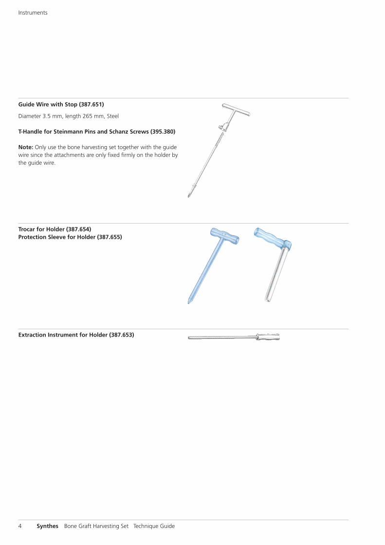
Guide Wire with Stop (387.651)
Diameter 3.5 mm, length 265 mm, Steel
T-Handle for Steinmann Pins and Schanz Screws (395.380)
Note: Only use the bone harvesting set together with the guidewire since the attachments are only fixed firmly on the holder bythe guide wire.
Trocar for Holder (387.654)Protection Sleeve for Holder (387.655)
Extraction Instrument for Holder (387.653)
Instruments

5
Indications
The Bone Graft Harvesting Set is indicated for obtaining auto -logous cancellous bone from the iliac crest or the lumbar spine.Autologous cancellous bone is used for:
– Bone defects, for instance after resection, that require defectfilling with autologous cancellous bone.
– Lumbar trauma or pathology requiring the use of interverte-bral implants. The intervertebral fusion of the vertebral bodiesinvolved can be achieved by inserting bone material into theimplant.
Contraindications
– Pathological changes of the bone substance (tumours, osteoporosis)
– Fractures at the harvesting site
– Severe instabilities or deformations at the harvesting site
Indications/Contraindications
Lateral and AP x-ray image: SynCage-LR on L4-L5 and L5-S1with posterior fixation. Local bone harvesting on L4, L5 anddefect filling with chronOS (dotted line).(Prof. Dr. Krismer, Universitätsklinik für Orthopädie, Innsbruck,Austria).

6 Synthes Bone Graft Harvesting Set Technique Guide
The iliac crest provides several donor sites for bone graft harvest-ing. Besides the posterior iliac crest, one major donor site is thearea around the internal lip of the iliac crest. Depending on theanatomical situation, up to three graft cylinders can be har-vested from this site. The drill depth is approximately 15 mm.Choose a diameter that corresponds to the width of the pa-tient‘s iliac crest. Experience shows that the diameter is between8.5 and 9.5 mm.
1Position the guide wire and protection sleeve
Once you have made an incision above the iliac crest, use the T-handle to insert the guide wire to the depth limitation (Fig. 1).
For a minimally invasive technique, use the trocar to insert theprotection sleeve over the guide wire to the iliac crest (Fig. 2).Removing the trocar provides access for bone harvesting overthe guide wire and the protection sleeve (Fig. 3).
Note: Do not apply extreme mechanical forces on insertion ofthe guide wire to avoid over insertion despite the depth limitingstop.
Harvesting at the Iliac Crest
Fig. 1
Fig. 3Fig. 2

7
2Drilling the bone dowel
Mount the appropriate trephine attachment (� 8.5 or 9.5 mm)onto the holder, and shove the holder over the guide wire.The holder may only be inserted in connection with the guidewire. Start drilling with oscillating movements. To penetrate hardcortical bone, it can be useful to use a hammer (399.420/399.430). Then continue drilling to the set drilling depth (settingring and locking nut on the holder).
Note: Do not apply extreme mechanical forces to the holder to avoid damage of the holder tip.
Note: Trephine attachment should not come in contact withmetal hardware to prevent breakage of trephine.
3Extraction of the bone dowel
Remove the holder.
Caution: In most cases, the bone dowel will be in the trephineattachment due to the large portion of cortical bone.
However, should the dowel still be in the iliac crest, remove thetrephine attachment and mount the appropriate extraction attachment. Slide the holder over the guide wire and use thehammer to insert the extractor until you reach the limited depth(Fig. 4). The T-handle may not rotate.
To break the graft dowel free, turn the holder slowly until youhear a cracking noise or feel no more resistance in turning. Remove the holder. Both the bone dowel and the guide wire remain in the extraction attachment (Fig. 5).
Fig. 4
Fig. 5

8 Synthes Bone Graft Harvesting Set Technique Guide
4Extract the bone dowel from the trephine attachment
To extract the graft dowel, insert the extraction instrument intothe holder. Use light hammer blows to remove both the doweland the guide wire (Fig. 6). You can use the autologous bonedowels to fill bone defects.
The table below indicates the volume of autologous bone graftto be harvested (cc) when using various drill diameters and drilldepths.
Drill depth Diameter
8.5 mm 9.5 mm 10.5 mm 12.5 mm 14.0 mm
15 mm 0.9 cc 1.1 cc 1.3 cc 1.8 cc 2.3 cc
20 mm 1.1 cc 1.4 cc 1.7 cc 2.5 cc 3.1 cc
25 mm 1.4 cc 1.8 cc 2.2 cc 3.1 cc 3.8 cc
If the amount of collected graft material is insufficient, we recommend mixing it with chronOS granules enriched with patient‘s blood.
5Prepare the chronOS cylinder
We recommend filling the defect caused by drilling with a syn-thetic, absorbable chronOS cylinder. The chronOS cylinder is provided in a perfusion syringe (Fig. 7). Perfuse the implant withblood to induce better osteointegration. To enhance osteo -inductive and osteogenic potential, chronOS can be perfusedwith bone marrow.
Fig. 6
Fig. 7
Harvesting at the Iliac Crest

9
First, select the bone substitute cylinder that corresponds to thediameter of the defect. Then connect the provided adapter and,if necessary, a hypodermic needle to the syringe. Draw 3 to 5 mlof the patient‘s blood or bone marrow (Fig. 8).
Remove the adapter, and perfuse the chronOS cylinder bypumping up and down several times (Fig. 9). Take care to avoidany formation of foam. In order to get rid of the surplus ofblood, connect the adapter again and press out the blood. Openthe front end of the syringe by turning the lid (Fig. 10). Use thesyringe plunger to eject the well-perfused implant, and insert itinto the appropriate implant holding attachment (Fig. 11).
Fig. 8
Fig. 9
Fig. 11
Fig. 10

10 Synthes Bone Graft Harvesting Set Technique Guide
6Implant the chronOS cylinder
Remove the extraction attachment from the holder, and attachthe prepared implant holder. Carefully insert the bone replace-ment cylinder into the defect (Fig. 12) and press it in furtherwith the implant impaction attachment until it is flush with thebone surface (Fig. 13 and 14).
Fig. 12
Fig. 13
Fig. 14
Harvesting at the Iliac Crest

11
Use an anterior or anterolateral access to collect bone graft.Carry out bone harvesting in lumbar vertebra L4 according to the anatomical situation. Select a drill depth of up to 25 mm,and determine the drill bit diameter according to the patient‘sanatomy. Experience shows that the diameter is between 12.5 and 14.0 mm.
1Preoperative planning
Please pay attention to the following when harvesting auto -logous bone graft from vertebral body L4 to fill an intervertebralimplant: If you fill a defect with a bone substitute cylinder in ananterolateral position, only use posterior translaminar screw fixa-tion of the intervertebral implant and not a transpedicular one.Transpedicular screw fixation could destroy or displace the bonesubstitute cylinder. You may use transpedicular fixation for ananteromedial cylinder, provided that the screws do not touch orperforate the implant.
2Position the guide wire
Once you have prepared vertebral body L4, position the guidewire anterolaterally, and use the T-handle to push it to the depthlimitation (Fig. 15).
Note: Do not apply extreme mechanical forces on insertion ofthe guide wire to avoid over insertion despite the depth limitingstop.
Fig. 15
Harvesting at the Lumbar Spine

12 Synthes Bone Graft Harvesting Set Technique Guide
3Position the protection sleeve
Insert the trocar into the protection sleeve, and slide both instru-ments over the guide wire down to the bone. First place the trocar on the bone, lower the protection sleeve and position iton the bone. Remove the trocar (Fig. 16). Positioning the protec-tion sleeve prevents exceeding the desired drill depth duringdrilling.
Fig. 16
Harvesting at the Lumbar Spine

13
4Drill the bone dowel
Mount the appropriate trephine attachment onto the holder.Adjust the desired drill depth on the holder using the settingring and the locking nut (Fig. 17).
Then slide the holder over the guide wire in the protectionsleeve. Start with oscillating movements, and drill until you reachthe desired depth i.e. when the locking nut on the holder con-tacts the upper rim of the protection sleeve (Fig. 16 and 18).You can also read the drill depth from the position of the guidewire in the window of the holder.
Remove the holder. Both the guide wire and the bone dowel remain in the bone (Fig. 19).
Note: Please note that you should only drill in combination withthe guide wire, since the guide wire locks the attachments ontothe holder.
Note: Do not apply extreme mechanical forces to the holder toavoid damage of the holder tip.
Note: Trephine attachment should not come in contact withmetal hardware to prevent breakage of trephine.
Fig. 17
Fig. 18
Fig. 19

14 Synthes Bone Graft Harvesting Set Technique Guide
5Extract the bone dowel
Remove the trephine attachment from the holder, and mountthe corresponding extraction attachment. Slide the holder againover the guide wire in the protection sleeve, and strike the extraction attachment until it reaches the selected drill depth.Do not turn the holder when inserting it into the bone.
The handle of the holder has been provided with a round strik-ing surface for striking the extraction attachment (Fig. 20).Please be careful not to strike the blue T-handle.
To break the graft dowel free, turn the holder slowly until youhear a cracking noise or feel no more resistance in turning. Remove the holder. Both the bone dowel and the guide wire re-main in the extraction attachment (Fig. 21). The extraction ofthe graft dowel may result in bleeding. You can stop it by usinga haemostatic agent while preparing the chronOS cylinder (see page 8).
Fig. 20
Fig. 21
Harvesting at the Lumbar Spine
15
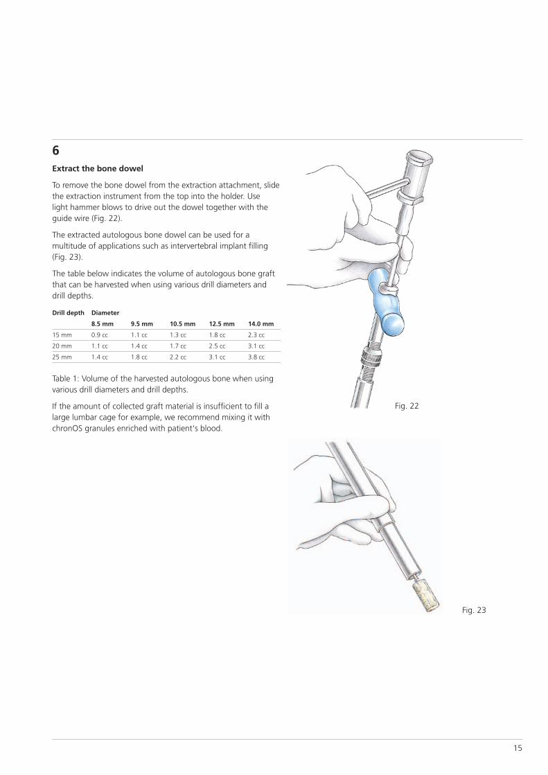
6Extract the bone dowel
To remove the bone dowel from the extraction attachment, slidethe extraction instrument from the top into the holder. Uselight hammer blows to drive out the dowel together with theguide wire (Fig. 22).
The extracted autologous bone dowel can be used for a multitude of applications such as intervertebral implant filling(Fig. 23).
The table below indicates the volume of autologous bone graftthat can be harvested when using various drill diameters anddrill depths.
Drill depth Diameter
8.5 mm 9.5 mm 10.5 mm 12.5 mm 14.0 mm
15 mm 0.9 cc 1.1 cc 1.3 cc 1.8 cc 2.3 cc
20 mm 1.1 cc 1.4 cc 1.7 cc 2.5 cc 3.1 cc
25 mm 1.4 cc 1.8 cc 2.2 cc 3.1 cc 3.8 cc
Table 1: Volume of the harvested autologous bone when usingvarious drill diameters and drill depths.
If the amount of collected graft material is insufficient to fill alarge lumbar cage for example, we recommend mixing it withchronOS granules enriched with patient‘s blood.
Fig. 22
Fig. 23

16 Synthes Bone Graft Harvesting Set Technique Guide
7Implant the chronOS cylinder
Remove the extraction attachment from the holder, and mountthe corresponding implant holding attachment. Place the ce-ramic bone substitute cylinder onto the implant holding attach-ment. Remove the haemostatic agent, and slightly bevel theedges of the hole to ensure an optimal insertion of the cylinderinto the defect. Use the holder to insert the chronOS cylinderinto the defect (Fig. 24).
Fig. 24
Fig. 25
Remove the implant holding attachment from the holder, andclick on the implant impaction attachment. It helps to pressthe bone substitute gently into the defect with the implant im-paction attachment until it is flush with the bone surface(Fig. 25).
Harvesting at the Lumbar Spine

17
Important instructions
– Cleaning: Use mild detergents and disinfectants to remove im-purities. Please follow the recommendations made by the detergent and disinfectant manufacturers. The set is made ofstainless steel and POM (polyoxymethylene).
– Sterilisation: Methods other than steam sterilisation in the autoclave up to 140°C are not suitable and can result in mal-function or damages of the system. (Unsuitable sterilisationmethods are for instance: hot air, vacuum, and plasma proce-dures).
– After steam sterilisation, take care to cool the instruments toroom temperature. The diameter of the trocar will expand under heat, and it may not fit into the protection sleeve whenused immediately after sterilisation. After reaching room temperature, it will reassume its original dimension.
– Additional instructions are found in the general Instructionsfor Use.
Cleaning and Sterilisation

18 Synthes Bone Graft Harvesting Set Technique Guide
The following additional implants and instruments are available:
chronOS cylinder, �-Tricalcium Phosphate, Porosity 70%Art. No. with Art. No. without Length DiameterPerfusion System Perfusion System 07.710.030S 710.030S 25 mm 8.5 mm07.710.031S 710.031S 25 mm 9.5 mm07.710.032S 710.032S 25 mm 10.5 mm07.710.033S 710.033S 25 mm 12.5 mm07.710.035S 710.035S 25 mm 14.0 mm
The cylinders come sterile in a perfusion syringe together withan adapter.
Hammer
Use the hammer to strike the extractor and to remove the col-lected bone graft from the extractor. Use it also to insert thetrephine at the beginning of drilling in particularly hard corticalbone (iliac crest).
399.420 Hammer 500 g399.430 Hammer 700 g
Additional Products

19
Art. No. Description Units177.300 Bone Graft Harvesting Set in SynCase 1
Case677.300 SynCase for Bone Graft Harvesting Set 1677.301 SynCase Basic Tray, including: 1
Small labelling plate for � 8.5 mm 1Small labelling plate for � 9.5 mm 1Small labelling plate for � 10.5 mm 1Small labelling plate for � 12.5 mm 1Small labelling plate for � 14.0 mm 1Small labelling plate, blank 1
677.302 Lid, labelled for No. 677.300
Instruments387.651 Guide Wire, � 3.2 mm, with Stop,
Length 265 mm 2387.653 Extraction Instrument for Holder 1387.654 Trocar for Holder 1387.655 Protection Sleeve for Holder 1387.657 Holder for Bone Graft Harvesting Set 1387.658 Implant Impaction Attachment for Holder 1387.659 Trephine Attachment, � 8.5 mm for Holder 1387.660 Trephine Attachment, � 9.5 mm for Holder 1387.661 Trephine Attachment, � 10.5 mm for Holder 1387.662 Trephine Attachment, � 12.5 mm for Holder 1387.663 Trephine Attachment, � 14.0 mm for Holder 1387.669 Extraction Attachment, � 8.5 mm for Holder 1387.670 Extraction Attachment, � 9.5 mm for Holder 1387.671 Extraction Attachment, � 10.5 mm for Holder 1387.672 Extraction Attachment, � 12.5 mm for Holder 1387.673 Extraction Attachment, � 14.0 mm for Holder 1387.674 Implant Holding Attachment, � 8.5 mm
for Holder 1387.675 Implant Holding Attachment, � 9.5 mm
for Holder 1387.676 Implant Holding Attachment, � 10.5 mm
for Holder 1387.677 Implant Holding Attachment, � 12.5 mm
for Holder 1387.678 Implant Holding Attachment, � 14.0 mm
for Holder 1395.380 T-Handle for Steinmann Pins and Schanz Screws 1
Ordering Information

20 Synthes Bone Graft Harvesting Set Technique Guide


Synthes GmbHEimattstrasse 3CH-4436 Oberdorfwww.synthes.com 0123 03
6.00
0.24
5 A
C
7010
0023
©
05/
2010
Syn
thes
, Inc
. or
its a
ffili
ates
A
ll rig
hts
rese
rved
Sy
nthe
s is
a t
rade
mar
k of
Syn
thes
, Inc
. or
its a
ffili
ates
Ö036.000.245öAC=ä
All technique guides are available as PDF files at www.synthes.com/lit