technics - replacement water filters · - technics av control stereo receiver sa-gx550 sa-gx350...
TRANSCRIPT

- TechnicsAV control stereo receiver
SA-GX550SA-GX350
Operating Instructions
I he photoglaphs show SA-GX550.
Before connecting, operating or adjusting thjs..product,read these if : ii:-_:
RQT1849-P
H 1292C0
Dear CustomerThank you for purchasing this Technics product.For optimum performance and safety, please readthese instructions carefully.
The model number and serial number of this product can befound on either the back or the bottom of the unit.
Please note them in the space provided below and retainthem for future reference.MODEL NUMBER .......................................SERIAL NUMBER .......................................
These operating instructions are applicable to models SA-GX550 and SA-GX350.
These operating instructions, however, are intended primarilyfor model SA-GX550.
WARNING:TO REDUCE THE RISK OF FIRE ORELECTRIC SHOCK, DO NOT EXPOSE THISAPPLIANCE TO RAIN OR MOISTURE.
CAUTION:TO PREVENT ELECTRIC SHOCK MATCHWIDE BLADE OF PLUG TO WIDE SLOT,FULLY INSERT.
CAUTION
CAUTION: TO REDUCE "[HE RISK OF
ELECTRIC SHOCK, DO NOT
REMOVE SCREWS.
NO USER-SERVICEABLE
PARTS INSIDE.
REFER SERVICING TO QUALIFIEDSERVICE PERSONNEL.
__lk The lightning flash with arrowhead symbol,
within an equilateral triangle, is intended toalert the user to the presence of uninsulated"'dangerous voltage" within the product'senclosure that may be of sufficient magnitudeto constitute a risk of electric shock to persons.
__IL The exclamation point within an equilateral
triangle is intended to alert the user to thepresence of important operating and main-tenance (servicing) instructions in the literatureaccompanying the appliance.

Before use Adjusting the sound field
Suggestions for safety ........................... 4Safety ................................................ 4Installation ............................................ 4Maintenance .......................................... 4Service ............................................... 4
Listening caution ...................................... 5
Accessories ........................................ 5Front panel controls .............................. 6
Control section ........................................ 6
Display section ........................................ 7
Connections
Equipment connections .......................... 8Connecting audio equipment ........................... 8Connecting video equipment ........................... 9
Antenna connections ............................. 10FM indoor antenna .................................... 10FM outdoor antenna ................................... 10
AM loop antenna ...................................... 11AM outdoor antenna ................................... 11
Speaker connections ............................. 12Placement of speakers ................................ 12Connection of front speakers ........................... 12Connection of rear speakers ........................... 13Connection of center speaker .......................... 13
Listening
Basic operations .................................. 14To listen to a desired audio source while watchingvideo picture .......................................... 15To adjust the sound balance ........................... 15To mute the sound level ............................... 15
To emphasize low-frequency sound I__.. • 15To adjust the tone quality .............................. 15When listening through headphones ..................... 15
Listening to radio broadcasts ................... 16Direct access tuning .................................. 16Sequential tuning _ ................... 17Sequential tuning _ ................... 18
Preset tuning ......................................... 18
Enjoying sound with DOLBY PRO LOGIC ..... 21SURROUND .......................................... 213 STEREO ............................................ 21
Setting the center mode ............................... 21Adjusting the delay time _ ............. 22Adjusting the output level of each speaker ............... 22Enjoying with SURROUND or 3 STEREO ................. 23
Recording
Making a recording ............................... 24Tape recording on the tape deck or digital compactcassette (DCC) ........................................ 24Recording from VCR 2 to VCR 1 ........................ 25VCR (VCR 1) recording from an audio source ............ 25To record picture from VCR 2 and sound froma different audio source ............................... 26
When there seems to be a
problem
Product service .................................... 26Product information ................................... 26
Troubleshooting guide ........................... 27
Reference
Technical specifications ............. Back cover
3

4
Belore using this unit please read these operating instructionscarefully. Take special care to follow the warnings indicated onthe unit itself as well as the safety suggestions listed below.Afterwards keep them handy for future reference.
Salty
1. Power Source -- The unit should be connected to power sup-ply only of the type described in the operating instructions oras marked on the unit.
2. Polarization -- If the unit is equipped with a polarized ACpower plug (a plug having one blade wider than the other),that plug will fit into the AC outlet only one way. This is a safe-ty feature. If you are unable to insert the plug fully into theoutlet, try reversing the plug. If the plug should still fail to fit,contact your electrician to replace your obsolete outlet. Donot defeat the safety purpose of the polarized plug.
3. Power Cord Protection -- AC power supply cords should berouted so that they are not likely to be walked on or pinchedby items placed upon or against them. Never take hold of theplug or cord if your hand is wet, and always grasp the plugbody when connecting or disconnecting it.
4. Nonuse Periods -- When the unit is not used, turn the poweroff. When left unused for a long period of time, the unit shouldbe unplugged from the household AC outlet.
Installation
Environment
1. Outdoor Antenna Grounding -- If an outside antenna is con-nected to the receiver, be sure the antenna system is ground-ed so as to provide some protection against voltage surgesand built-up static charges. Section 810 of the National Elec-trical Code, ANSIINFPA No. 70-1990, provides informationwith respect to proper grounding of the mast and supportingstructure, grounding of the lead-in wire to an antennadischarge unit, size of grounding conductors, location ofantenna-discharge unit, connection to grounding electrodes,and requirements for the grounding electrode. See figurebelow.
CLAMP
ANTENNA
LEAD IN
WIRE
ANTENNA
DISCHARGE UNIT
(NEC SECTION 810-20)
,?,ONDUCTORS
)-21)
CLAMPS
POWER SERVICE GROUNDINGELECTRODE SYSTEM
(NEC ART 250, PART H)
NEC- NATIONAL ELECTRICAL CODE
2. Water end Moisture -- Do not use this unit near water- for ex-
ample, near a bathtub, washbowl, swimming pool, or the like.Damp basements should also be avoided.
3. Heet -- The unit should be situated away from heat sourcessuch as radiators and the like.
It also should not be placed in temperatures less than 5°C(41° F) or greater than 35°C (95 ° F).
Placement
1. Ventilation -- The unit should be situated so that its Locationor position does not interfere with its proper ventilation. Allow10 cm (4") clearance from the rear of the unit.
2. Foreign Material -- Care should be taken so that objects donot fall into and liquids are not spilled into the unit. Do not sub-ject this unit to excessive smoke, dust, mechanical vibration,or shock.
3. Magnetism -- The unit should be situated away from equip-ment or devices that generate strong magnetism.
4. Stacking -- Do not place heavy objects, other than systemcomponents, on top of the unit.
5. Surface -- Place the unit on a flat, level surface.6. Carts and Stands -- The unit should be used only with a cart
or stand that is recommended by the
manufacturer. The unit and cart combinationshould be moved with care.
Quick stops, excessive force, and unevensurfaces may cause the unit and cart com-bination to overturn.
7. Wall or Ceiling Mounting -- The unit should not be mountedto a wall or ceiling, unless specified in this operating instruc-tions.
Maintenance
Clean the cabinet, panel and controls with a soft cloth lightlymoistened with mild detergent solution.
Do not use any type of abrasive pad, scouring powder or solventsuch as alcohol or benzine.
Service
1. Damage Requiring Service -- The unit should be serviced byqualified service personnel when:(a) The AC power supply cord or the plug has been damaged;
or
(b) Objects have fallen or liquid has been spilled into the unit;or
(c) The unit has been exposed to rain; or(d) The unit does not appear to operate normally or exhibits a
marked change in performance; or(e) The unit has been dropped, or the enclosure damaged.
2. Servicing -- The user should not attempt to service the unitbeyond that described in the operating instructions. All otherservicing should be referred to qualified service personnel.

Listening caution
@Selecting fine audio equipment such as the unit you've just pur-chased is only the start of your musical enjoyment. Now it's timeto consider how you can maximize the fun and excitement yourequipment offers. This manufacturer and the Electronic In-dustries Association's Consumer Electronics Group want you to
get the most out of your equipment by playing it at a safe level.One that lets the sound come through loud and clear without an-
noying blaring or distortion- and, most importantly, without affec-ting your sensitive hearing.
Sound can be deceiving. Over time your hearing "comfort level"
adapts to higher volumes of sound. So what sounds "normal"can actually be loud and harmful to your hearing.Guard against this by setting your equipment at a safe levelBEFORE your hearing adapts.To establish a safe level:
• Start your volume control at a low setting.• Slowly increase the sound until you can hear it comfortably and
clearly, and without distortion.
Once you have established a comfortable sound level:• Set the dial and leave it there.
Taking a minute to do this now will help to prevent hearingdamage or loss in the future. After all, we want you listening for alifetime.
We Want You Listening For A LifetimeUsed wisely, your new sound equipment will provide a lifetime offun and enjoyment. Since hearing damage from loud noise isoften undetectable until it is too late, this manufacturer and theElectronic Industries Association's Consumer Electronics Group
recommend you avoid prolonged exposure to excessive noise.This list of sound levels* is included for your protection.*The level used here is different from that displayed on the
system's display.
DecibelLevel
3O4O
5O6O7080
ExampleQuiet library, soft whispersLiving room, refrigerator, bedroom away from trafficLight traffic, normal conversation, quiet officeAir conditioner at 20 feet, sewing machineVacuum cleaner, hair dryer, noisy restaurantAverage city traffic, garbage disposals, alarm clock attwo feet
THE FOLLOWING NOISES CAN BE DANGEROUS UNDERCONSTANT EXPOSURE
90 Subway, motorcycle, truck traffic, lawn mower100 Garbage truck, chain saw, pneumatic drill120 Rock band concert in front of speakers, thunderclap
140 Gunshot blast, jet plane180 Rocket launching pad
Information courtesy of the Deafness Research Foundation.
Please check and identify the supplied ac-cessories
[_] AC supply cord 1 pc.power(For USA: SJA172-1)(For Canada: SJA172)
[] AM loop antenna set (SPB1163T)• AM loop antenna ........................ 1 pc.• AM antenna holder ...................... 1 pc.• Screws ................................ 2 pcs.
[_ FM indoor antenna (RSA0006) ............... 1 pc.
/ Remote control transmitter 1 pc.For SA-GX350 For SA.GX550
(RAK-SA006MH) (RAK-SA901 MH)
For details on remote control transmitter opera-tion, refer to "How to use the remote controltransmitter" in the separate booklet.
Batteries (UM-4, "AAA", R03) ............... 2 pcs.
5

Control section
SA-GX550
No. Name
Power switch (POWER)
Tuning control (TUNING)
Re[. page
14
17
Tuning buttons (TUNING) 18
Tuning mode select button(TUNING MODE) _ 17
_) Numeric buttons (1-0) 16,19,20
(_ DOLBY PRO LOGIC SURROUNDONIOFF button (SURROUND) 21,22,23
(_) DOLBY PRO LOGIC 3 STEREOONIOFF button (3 STEREO) 21,22,23
Q_)Test signal ONIOFF button (TEST) 22
(_) Center level adjust button(CENTER LEVEL) 23
(_) Rear level adjust button(REAR LEVEL) 23
(_) Center mode select button(CENTER MODE) 21
(_) Memory button (MEMORY) 19
No. Name Re[. page
(_) Muting button (MUTING) 15
(_) Volume control (VOLUME) 14
(_) Headphone jack (PHONES) 15
(_) Direct tuning button(DIRECT TUNING) 16
(_) Speaker select buttons (SPEAKERS) 14
(_ Band select button (BAND) 16
(_) FM mode select button (FM MODE) 16
(_) Input select buttons 14
_) TapelDCC monitor button(TAPE/DCC [MONITOR] ) 14,24
(_) Delay time adjust button(DELAY TIME) _ 22
(_) Loudness ONIOFF button(LOUDNESS) _ 15
(_ Balance control (BALANCE) 15
(_ Bass control (BASS) 15
(_) Treble control (TREBLE) 15

Display section
OVER
i-,'
7
/"[TAPE MONITOR I
/DE
It:,o-:;.
NO. Nalne
2_ Remote control signal receptori,._,_,Xt.]_o] L'S'_i_,j
(_ Overload indicator
Tuning-mode indicatorsm_rn_
2_ Quartz lock indicator
Memory indicator
Tape monitor indicator
Delay time indicator/ ;mi_A
VCR select indicator
Loudness indicator
(_ DOLBY PRO LOGIC SURROUNDindicator
DOLBY PRO LOGIC 3 STEREOindicator
Re?. page
n
27
17
16
19
14,24
22
25
15
21,22,23
21,22,23
No. Name
(_ Low impedance indicator
(_ Speaker select indicators
Band indicators
FM stereo indicator
Input selector/frequency display
(_ Muting indicator
(_ Center/rear level display
(_ Center mode indicators
Re[. page
14
14
16
16
15
23
21
7

Connecting audio equipment
I tereo connection cable (not included)White (L)Red (R)
CD changer (or CD player)(not included)
OUTPUT
Only for turntablewith ground terminal
• TAPE/DCC
REMOTE(_) (_ CONTROl
OUT@@ ®
REC (IN)
PLAY (OUT)
L
Tape deck or digital compact cassettedeck (DCC) (not included)
rn [ZZIIZEl
_ Speaker terminalsSee pages 12- 13.
Turntable
(not included)
[[ l]ooo@@@ oooO
O O _ c:]z:]
i i
ACOUTLET_
1
r REMOTE(l)CONTROL
_L._ 0UT
1
onoect'oor i /cable for OUT
remotecontroi/ i _(_REMOTE(not included) CONTROL
i This unit
!
cords
(not included)
-I Tape deck
FTi]I_ I (not nc uded)
CD changer(or CD player)(not included)
r_ "REMOTE CONTROL OUT" terminalConnect the connection cable for remote control to a
Technics tape deck andlor CD changer (or CD player) whichhas the appropriate remote control terminal as shown at theleft.
If a tape deck is not being used, the CD changer (or CDplayer) can be connected directly (dotted line).
® "SWITCHED" AC outlet(s)Power to these outlets is controlled by the power switch ofthis unit. Audio equipment rated up to the indicated powerratings can be connected here.
For proper remote.control operation
Connect the power cords of the tape deck and CD changer(or CD player) to these outlets as shown at the left.
[,."}'_[mBecause there is only one AC outlet, connect the power cord
of the CD changer (or CD player) to the AC outlet of the tapedeck.

Connecting video equipment
Stereo connection cable (not included) [
IRed (R)
Second VCR (for playback only)(not included)
AUDIO VIDEOOUT OUT
_QO@o@
o4,0 @VCR2IN
VCR1IM
AUDIOIN
VCR
(not included)
-'1
IAUDIOOUT
VIDEO
OUT
Video connection cables
not included)
Monitor TV
(not included)
VIDEOIN
jr
13/"--IMONITORIN I OUT
@
Cooling fanThe cooling fan operates at highpower output levels only.
VIDEOIN
connection cables
(not included)
ACOUTLETS
!
I onnect this cord after Iall other cables andcords are connected.
AC power supply cord
(included)
Household AC outlet
(AC 120 V/60 Hz)
9
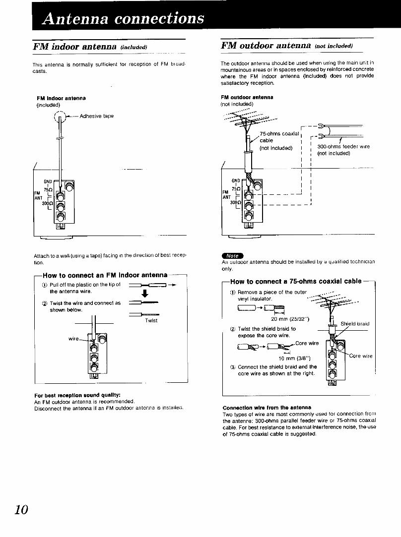
FM indoor antenna ti.cl.aed)
This antenna is normally sufficient for reception of FM broad-casts.
FM indoor antenna
(included)
(n_]_;_---- Adhesive tape
/___
6ND
FM 75{_._ANT [-
3o_
1_ =.J
FM outdoor antenna t.ot included)
The outdoor antenna should be used when using the main unit in
mountainous areas or in spaces enclosed by reinforced concretewhere the FM indoor antenna (included) does not providesatisfactory reception.
FM outdoor antenna
(not included)
I-----_'s coaxial I _ )
_" ,,"/'cable I -- f
J (not included)I I _n00-Ohc/Sdfeed_der wire
' I6ND i=r_ _ I
IN --
mAttach to a wall (using a tape) facing in the direction of best recep-tion.
--How to connect an FM indoor antenna--
Pull off the plastic on the tip ofthe antenna wire.
_?_Twist the wire and connect asshown below.
wit,
Twist
An outdoor antenna should be installed by a qualified technician
only.
--How to connect a 75-ohms coaxial cable--
Remove a piece of the outer
vinyl insulator.
20 mm (25132")
(2_ Twist the shield braid toexpose the core wire.
_3---_ _)_Core wire
10 mm (3/8")
3_) Connect the shield braid and thecore wire as shown at the right.
Shield braid
wire
For best reception sound quality:An FM outdoor antenna is recommended.Disconnect the antenna if an FM outdoor antenna is installed. Connection wire from the antenna
Two types of wire are most commonly used for connection fromthe antenna: 300-ohms parallel feeder wire or 75-ohms coaxialcable. For best resistance to external interference noise, the useof 75-ohms coaxial cable is suggested.
20
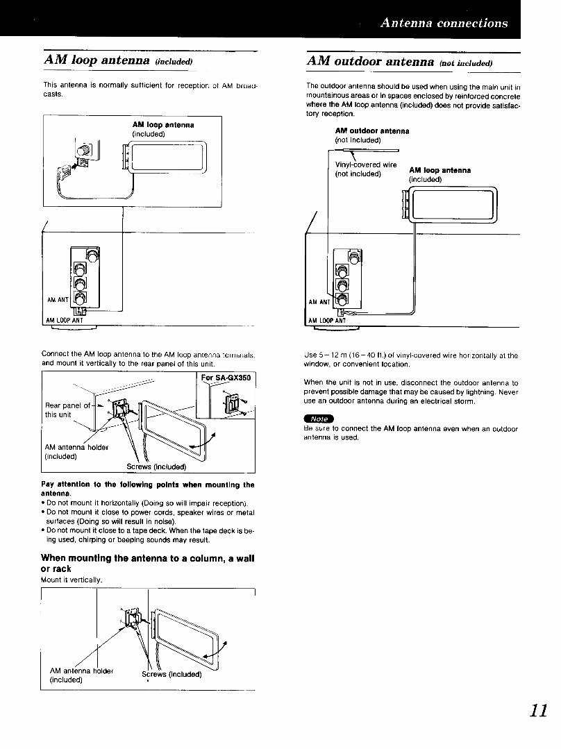
AM loop antenna _i.cl.aea) AM outdoor antenna _.ot i.ciudea)
This antenna is normally sufficient for reception ol AM broad-casts.
AM loop antenna(included)
A ANTIIAM LOOPANT
I...__.J
The outdoor antenna should be used when using the main unit inmountainous areas or in spaces enclosed by reinforced concretewhere the AM loop antenna (included) does not provide satisfac-tory reception.
/
AMAN
AM LOOPANTt,,, j
AM outdoor antenna
(not included)
Vinyl-covered wire(not included) AM loop antenna
(included)
Connect the AM loop antenna to the AM loop antenna tem_ir_als,and mount it vertically to the rear panel of this unit.
Rear panelthis unit
For SA-GX350
AM antenna holder
(included)
Screws (included)
Pay attention to the following points when mounting theantenna.
• Do not mount it horizontally (Doing so will impair reception).• Do not mount it close to power cords, speaker wires or metal
surfaces (Doing so will result in noise).• Do not mount it close to a tape deck. When the tape deck is be-
ing used, chirping or beeping sounds may result.
When mounting the antenna to a column, a wallor rackMount it vertically.
Use 5- 12 m (16-40 ft.) of vinyl-covered wire horizontally at thewindow, or convenient location.
When the unit is not in use, disconnect the outdoor antenna to
prevent possible damage that may be caused by lightning. Neveruse an outdoor antenna during an electrical storm.
Be sure to connect the AM loop antenna even when an outdoorantenna is used.
AM antenna holder Screws (included)(included)
11

9 r, Jr'41
]2
Placement of speakers
As well as enjoying normal stereo reproduction with both the leftand right front speakers connected, a center speaker and rearspeakers can also be connected to the main unit in order to enjoyplayback with a feeling of presence using the Dolby Pro-Logic
Systems.
The illustration below shows where to place the speakers whenenjoying sound with Dolby Pro-Logic systems.The listening position at which the effect is the greatest is a posi-tion slightly to the rear of a center position of five-speaker
systems.However the position should be adjusted to your personalpreference, because the effect varies to some degree dependingupon the type of music and the music source.
Front speaker Front speaker(not included) (not included)(Left) (Right)
Center speaker(not included)
Rear speaker Rear speaker(not included) (not included)(Left) (Right)
Connection of front speakers
Right speaker Left speaker(not included) (not included)
(notThis unit
1 15 mm 2
Twisto
3
To prevent damage to circuitry,never short-circuit positive (+) andnegative (-) speaker wires.
• "B" terminalsFor connection to a second pair of speakers.
m Speakerimpedance
When only the "A" or only the "B" speakers are con-nected:
The impedance of the speaker used with this unit must be 4-8
If 4 _ speakers are connected, be sure to set the impedance onthe main unit to LOW according to step 2 on page 14.
When both the "A" and the "B" speakers are con-nected simultaneously:The impedance of the speaker used with this unit must be 8 _.
The impedance of any speaker used with this unit must be 8 _.
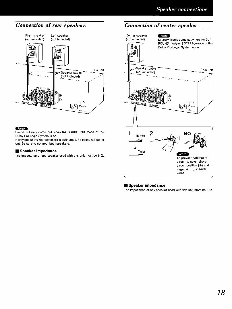
Connection of rear speakers Connection of center speaker
Right speaker Left speaker(not included) (not included)
This unit
Center speakernot included)
_cluded)
Sound will only come out when the SUR-ROUND mode or 3 STEREO mode of the
Dolby Pro-Logic System is on.
This unit
Sound will only come out when the SURROUND mode of theDolby Pro-Logic System is on.If only one of the rear speakers is connected, no sound will comeout. Be sure to connect both speakers.
i SpeakerimpedanceThe impedance of any speaker used with this unit must be 8 _.
_1, Twist
NO
To prevent damage tocircuitry, never short-circuit positive (+) andnegative (-) speakerwires.
• Speaker impedanceThe impedance of any speaker used with this unit must be 8 £}.
13

V 2 3 5
0
POWER TAPE/DCC VOLUME
Belore operation, set VOLUME to the "0" position.
............POWE. .... Press PO WER tO Switch 0n
_ _ the power.
[ cJ J sPEAK_-RS.... PressAandioiBto selectA B the speaker system(s) to be
k,_ _ A and B refer to the speaker terminals"_' at the rear of the unit.
I...._o :/•"_,_,,,, L'.";'f'"_ l
IIlluminates
If the button is pressed once more, theindicator will switch off and no sound
will be heard from the speakers.
_' ................ Press to seiect the desiredsource.VCR 1: To watch video tapes (VCR 1)
[__ VCR 2" To watch video tapes (VCR 2)TAPE/DCC- To listen to tape or digital
compact cassette (DCC)The tape monitor in-dicator will appear.(See below.)
CD: To listen to compact discsTUNER: To listen to radio broadcasts
PHONO: To listen to phono discs
(Refer to the appropriate operating in-structions for details.)
When using speakers with an im-pedance of 4 Q, press either button Aor button B for 4 seconds or more toset the impedance on the main unit toLOW.
MA_ACLOOK
_'_'_" I'Z_ l'_ I
_w,.%-] CI I-J. IIlluminates
In this condition, speakers A and Bcannot both be used at the same time.
_.j " _0LU'ME.... Turn VOLUME io adjust the
_ volume level.
After listening is finishedBe sure to reduce the volume level, and switch the power to thestandby condition by pressing POWER.
When tape monitor indicator illuminates or isflashing (approx. 3 seconds)This indicates that the tape monitor function of this unit is ON.To listen to sources other than a tape or DCC, be sure to turn offthe indicator by pressing TAPE/DCC _.
Illuminates or flashing
I_- AUT O I
MANUAL {TAPE MONIT_)RJ I_LOCK

f
/
_PLAKLHS
'L'_....
O :T_u.K
0
I
BALANCE
OMUTING
©
I
VOLUME
Headphones (not included)Plug type:1/4 inch phone plug stereo type
LOUDNESS BASS TREBLE
F---I © ©
To listen to a desired audio source
while watching video picture
1. Follow steps 1 -2 at the left.
2. Select the desired video source and audio
source in step 3 at the left.Be sure to select the video source first.
3. Start the video and audio source.
To emphasize low-frequency sound
LOUDNESS Press LOUDNESS._,-,,,UTO _liI
MANUALLOCK
SPEEAKIERS f";` i'"'_ [ LOUDNESS
,,,, .,'-7!2;'. I "' IIlluminates
Press once again to turn it off.
To adjust the sound balance
BALANCETurn BALANCE to adjust
leftlright sound balance.
the
To mute the sound level
MUTING Press MUTING.P'AUrO
LOCK ..........SPEAKERS i J [ / :
,-,-, ,,,, ..'.::3C;'.MUTING
"!Illuminates
The volume level is attenuated by approx., 20 dB
(1/10).IIla,a_l
Press once again to return to the previousvolume level. (The muting indicator will turn off.)
To adjust the tone quality
BASS Turn BASS to adjust the Iow-fre-
_ quency sound.
TREBLE Turn TREBLE to adjust the high.fre.
quency sound.
When listening through head-
phones
Use VOLUME to reduce the volume level, andconnect the headphones.If sound from speakers is not wanted, press SPEAKERS (A)and/or (B) to turn off the speaker select indicators,
Avoid listening for prolonged periods of time to prevent hearingdamage.
15

Direct access tuning
Specify the frequency using the numeric buttons to directly tuneto the desired broadcast station.
0_R _s
C3 ©
m:T_
6x
32 14
...................................................................................................................:1L_ Press TUNER ..... ,_
• MANUAL
LOCK ..........S_EAKE_ L" L...J 'm ,_ L...I I.....!.
1r......... BAND............ Press BAN D tO select "FM " ""o'r ......... :.F_:....................... __iI "AM" ...... _.::::__.::::;
• I m illu:!nate s L.../L'. --)
DIRECTTUNING Press DIRECT TUNING.
While cursor display is flashing
,__pprox. 4 seconds)
I =-AUTO :_/
MANUALLOCK
SPEAKERS
m m xl/i'i'_
Press the appropriate numeric but-tons to enter the frequency.FM frequencies can be entered at tuning intervals of 100kHz, and AM frequencies at tuning intervals of 10 kHz
If no button is pressed while the cursor display isflashing, the display will return to the frequency which iscurrently being received. To re-specify the frequency,repeat the procedure from step 3.
If the desired FM frequency is 107.9MHz
/
%._,oALQUArtzLOCK =_(,._RS,._ J f:_ Fi _::_
m _ i /.....I !......!Illuminates when tuned
When the FM stereo broadcast is received:This unit will automatically switch to FM stereo reception and theFM stereo indicator will illuminate.
=.AmO _-_-_-_-_-_-_-_-_-_mzLOCK _B_MANUALLOCK
SPE,KERSSTEREO I I'') /'"') I._)
Illuminates
If noise is excessive in the FM stereo modePress FM MODE (The FM stereo indicator will switch off.)The broadcast will be monaural, but noise will be reduced. If the
button is pressed once more, stereo mode will be resumed.
16

Sequential tuning
If the frequency is not known, use the tuning control for sear-ching.
Auto tuning
This automatically searches for broadcast stations which providestrong signal reception.
TUNING TUNING MODE
432 1
_._ "_' Press TUN ER: .................
_ BAND Press BAND to select "FM"or "AM".
TUNINGMODEPress TUNING MODE to
Q_ select "AUTO".The • mark points to AUTO.
L_'"AUTO :LU t_._.s !') 1'"" ,-'m .., (::) L::J.
_ Turn TUNING until the fre-
quency begins to change.
Automatically stops when a broadcaststation is found.
41_11JTuning may stop automatically if anyjamming is encountered.
Manual tuning
The frequency will change only by the amount that the tuning con-trol is turned.
Q ) 6
)
432 1
_ '_" 'Press TUNERI .................
..... BAND...... Press BANDto Select "FM'
or "AM".
'" TUNING"MOIRE''Press TuNiNG "MODE " to
Q_ select "MANUAL".}_"'_ The • mark points to MANUAL.
v I_ MANUAL /
A_,,, (::j _:::) i \/.....//...../. / ,,, )QD FM
..... -ILo";_G..... Turn ;ruNING t; tone tO ihe
:::'::t: t:r::e:_::tb;oadc ast st a -
tion is obtained.
Tuning IntervalsFM: 200 kHz intervalAM: 10 kHz interval
To lock a broadcast station being receivedPress TUNING MODE to select "LOCK".
The • mark points to LOCK.
Auxo QUARTZ_ _%MANUAL
lb. LOCKSPE,KE,S,_.._O I I"'_ /"';' i"'/,. t #_/ t...-.)
During this display, the frequency will not change even if TUNINGis turned.
17

Sequential tuning
If the frequency is not known, use the tuning buttons for sear-ching.
J
3 2 1
Pr.ssruN;="I.................
BAND Press BAND to select "FM"
or "AM".
.... .....Pr."OOw"orUPtot,.,"eDOWN UP| to the desired broadcast.
I [ | Tuning IntervalsFM: 200 kHz interval
AM: 10 kHz intervalIf either button is pressed and helddown, the broadcast stations can betuned automatically (see below).
To automatically search for broadcast stationsPress DOWN or UP until the frequency begins to change.Automatically stops when a broadcast station is found.QTuning may stop automatically if any jamming is encountered.
Preset tuning
By presetting the desired broadcast stations into the memorychannels of this unit, broadcast stations can be selected simplyby pressing numeric button(s). (Refer to page 20 for tuning.)
-Before presetting
How many broadcast stations can be preset?A total of 30 FM and AM stations can be preset.
How is presetting done?The two following methods are available.
• Automatic memory presettingAutomatic memory presetting allows this unit to automatical-ly search for broadcast stations and then preset them into
memory.With this function, searching proceeds from the frequencycurrently being displayed and continues through higher fre-quencies, (up to 107.9 MHz for FM, up to 1710 kHz for AM)and broadcast stations are preset In the order in which theyare located.
With this method, the channel ranges that can be preset intothe memory for different bands (FM or AM) are set asfollows.
Channel
For FM broadcast stations ........................ 1 -30For AM broadcast stations ....................... 21 -30
If the FM stations (channels 1-30) ere preset and thenthe AM stations (channels 21-30) are preset:Because this unit can accommodate a total of 30 presetchannels, the settings for FM channels 21 - 30 will be replac-ed by the AM settings which were subsequently preset, andthe channel allotment will be as shown below.
For FM broadcast stations ........................ 1 -20For AM broadcast stations ....................... 21 -30
• Manual memory presettingThe desired broadcast stations can be preset into thedesired channels by the user.This can also be used as a method for changing selectedbroadcast stations that were preset in "Automatic memorypresetting".
Please remember this:If a new broadcast station is preset into a channel, the set-ting for the broadcast station which was previously enteredin that channel will be automatically erased.
8

Automatic memory presetting Manual memory presetting
fJ
_ [ ]
2 1 4
/_ '_' ' Press TUNERI .................
BAND Press BAND to select "FM"
(_ or "AM".
................ Settothe frequencY fromwhich you want to startautomatic memory preset-ting. (Refer to page 16.)
,4 _ .... _ Press MEMoRYuntlithe fre.
I.._.._ I...._.,11 quency begins to change.t_ _ (Automatic memory presetting will
",,,.,) start.)
To stop press MEMORY once again.
When a broadcast station is presetThe memory indicator and the preset channel number will bedisplayed for approximately 1 second.
I_ AUTO CX_TZ LOCK
MANUAL
LOCK MEMORY ('"" ! /Qo _. II
--rIlluminates
f I
When presetting is completedThe last broadcast station to be preset will be displayed.
Correct presetting may not be possible in cases where the broad-cast waves are too strong or too weak. In such cases, carry outpresetting manually.
J
©:!: ......52 1 4
]_ "_ Pres,,:ru,E,:.................
_I_ ... B:','ND....... Press BANDto select ,FM,,
or "AM".
................ Set t0 thedesired br0ad.
cast.(Refer to pages 16-18.)
................ Press MEMoRY m0mentaii.
LOCK MEMORY ...............SPEAKE"S_ I I / 1 I I I \
Illuminates
To cancel the memory function, pressMEMORY again.
"__]' SPecifythe desi;ed channeito be preset using theL,, / numeric button(s) (com-
v pletes presetting).(Example: Channel 12)
(Within 2 sec.)
ID"AUTO _I
MANUALLOCK MFJ_ORy
SPEAKERS t/ ..... [ j
: i'"') /\1/(_3 -'..... , _ • .....
/t\Off Preset channel
r..........1 ILOCI< r" -- "1
...... _.... f i i f.:3L...I3 //. ....
To continue presettingRepeat steps 2 through 5.
19
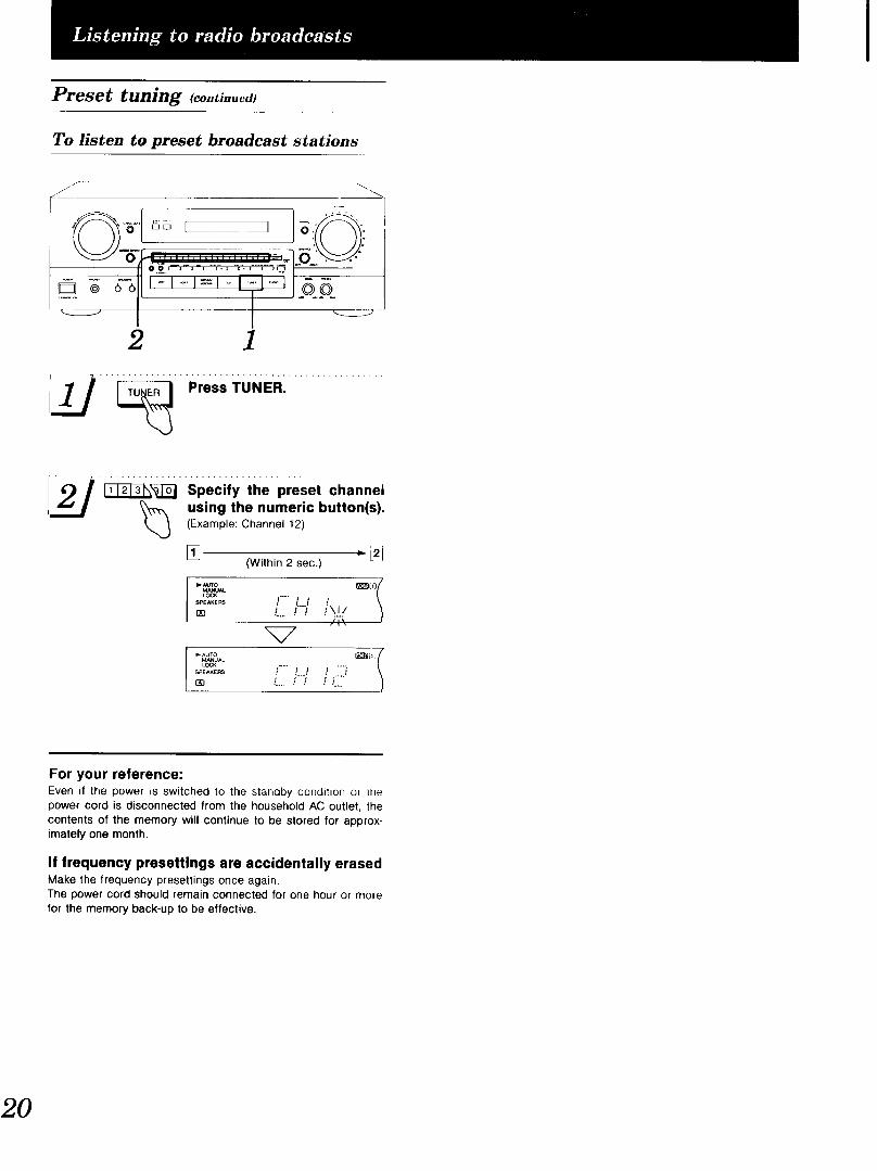
Preset tuning _co...ued_
To listen to preset broadcast stations
S
D @ oo
2 1
_ " _' "Press :FUNERI .................
2 1__ specify the preset channel/.__J _ using the numeric button(s).
(Example: Channel 12)
[] ,_i2j(Within 2 sec.)
=,.Au'ro _Oj/
MANUALLOCK .....
SPEAKE"S ! /.....i iL.. / / i\.!./
/1\
b AUTO _b_ /MANUAL
LOCK .....
....... i ..,./ /... ,Z,
For your reference:Even it the power is switched to the standby condition or thepower cord is disconnected from the household AC outlet, the
contents of the memory will continue to be stored for approx-imately one month.
If frequency presettings are accidentally erasedMake the frequency presettings once again.The power cord should remain connected for one hour or morefor the memory back-up to be effective.
20

By combining front (A or B), center and rear speakers, SUR-ROUND mode which conveys a feeling of presence or 3 STEREOmode which conveys a feeling of orientation can be enjoyed.
SURROUND
By reproducing the feeling of depth and movement of sound,video software or compact discs recorded with Dolby Surroundprovide the listener with a feeling of presence like that of a movietheater.
To enjoy SURROUND, be sure to connect the rear speakers.
Front Center Front
speaker (L) speaker speaker (R)
Rear I---q Rearspeaker (R)speaker (L)
3 STEREO
Music and news programs with clear sound and a good feeling oforientation can be enjoyed.
To enjoy 3 STEREO, be sure to connect the center speaker.
Front Center Front
speaker (L) speaker speaker (R)
Rear r---] _----_ Rearspeaker (L) .... '_ .... _ speaker (R)
Manufactured under license from Dolby Laboratories Licens-ing Corporation. Additionally licenced under one or more ofthe following patents: U.S. numbers 3,632,886, 3,746,792 and3,959,590; Canadian numbers 1,004,603 and 1,037,877."Dolby" and the double-D symbol are trademarks of DolbyLaboratories Licensing Corporation.
Setting the center mode
For Dolby Pro-Logic systems, center mode setting is necessaryto play back bass sounds effectively.Set the center mode in accordance with the size of your center
speaker.
"-', ":
1 2 3"'SPEAK'F'RS.... Presskor"BtO select the
AA speaker system to be used."_ "J"\M-,-, I .... _®/
Illuminates
r_su..ou.D ....P;essSoRi_ouNDor3STEREO to turn on the
I_ desired mode.",,.) For SURROUND mode
_o_ OOor /.!_]IL-;I' -- ,_-__.[.-.........
Illuminates3 STEREO For 3 STEREO mode
°" iC_. / ,._ "-"_"-............_.............I
Illuminates
Press once again to turn it off.
''&"TE.,;O;;_'P_essCeNI:I=RMODEi0select correctthe center
"_'_'_" mode."_ _,.......... "_ °°_i
_i...j i...j i NO_. I
/Ill, t .... 1" "1The indicator changes each time thebutton is pressed.NORMAL:
When the center speaker is smallerthan the front speakersWIDE BAND:When the center speaker is the same
size as the front speakersPHANTOM: I'I[1111 :Illli#, Ibi.] iii,iWhen no center speaker is con-nected.
In the PHANTOM mode, the soundfrom the center speaker will be divid-ed between both the left and right
front speakers.
21
22
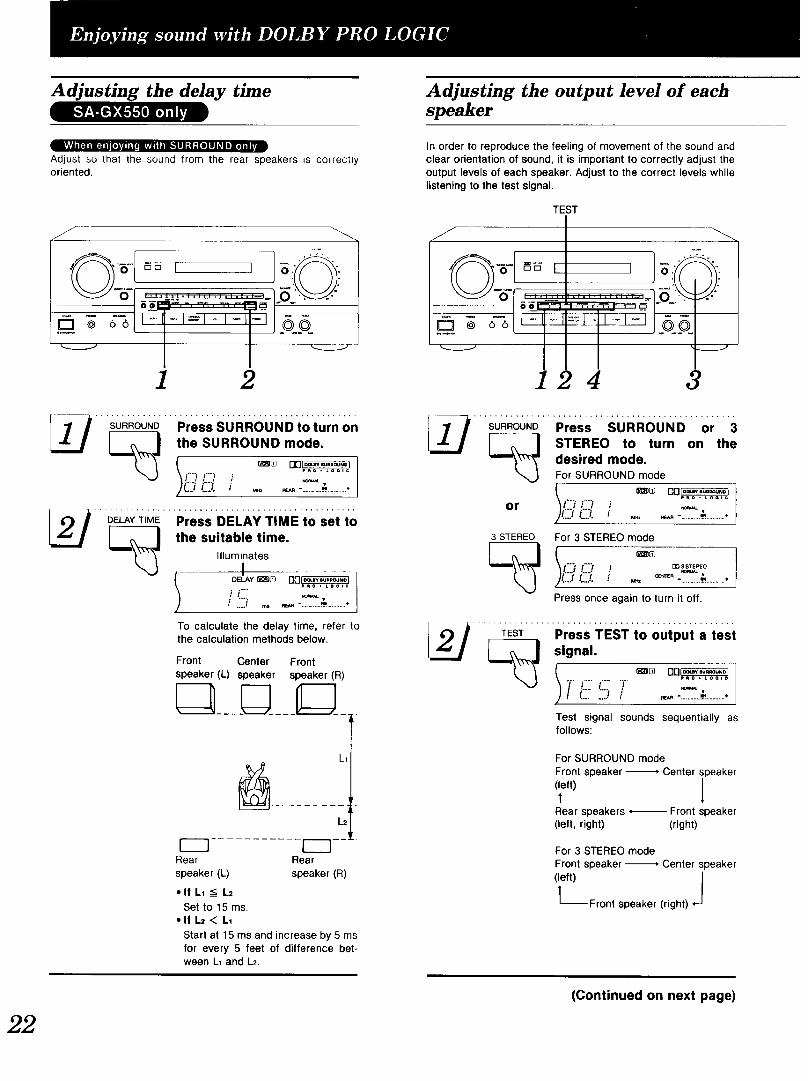
Adjusting the delay time
lVlVh [q imqll ,_,l,_l_ -,v,vnI i'lk1.ll "! :[O]U _I iii]n _
Adjust so that the sound trom the rear speakers is correctlyoriented.
J
1 2
SURROUNDPress SURROUND to turn on
J the SURROUND mode.
_J \ L...i /...../ ,_ .)C_¢:_. ._ .__-............._.............
__./ DELAYT,ME""Press DELAYTiMEtO sei t0,,o.,=,o,,oo.OELAY _)O [][]_
p_o • Loolc
ii, .....I ._ _._ -............,].............
To calculate the delay time, refer tothe calculation methods below•
Front Center Frontspeaker (L) speaker speaker (R)
Rear
speaker (L)
• If LI __ L2
L1
L2
1---_ --!
Rear
speaker (R)
Set to15ms.• If L= < L1
Start at 15 ms and increase by 5 msfor every 5 feet of difference bet-ween L1 and L2.
Adjusting the output level of eachspeaker
In order to reproduce the feeling of movement of the sound andclear orientation of sound, it is important to correctly adjust theoutput levels of each speaker. Adjust to the correct levels whilelistening to the test signal•
TEST
J
_r m
i .... =_ .. i,-I-i .q_o@ 66
4 3
SURROUNDPress SURROUND or 3
to turn on theSTEREO
"_'_" desired mode.For SURROUND mode
C?or J _v
3 STEREO For 3 STEREO mode
I"'_ !"'? mp%_TEr,EOC_Q. ... ='"-. ..........._.............
Press once again to turn it off.
_L__J_Pro" Ti_STi0oot,,i,t,si_J signal.
_ ---__-,., 1,!:_; / ..-_.,............
Test signal sounds sequentially asfollows:
For SURROUND mode
Front speaker -_ Center speaker
(left)1' l
Rear speakers *_ Front speaker(left, right) (right)
For 3 STEREO mode
Front speaker-m" Center speaker
(left) J--Front speaker (right)
(Continued on next page)

Enjoying with SURROUND or3 STEREO
{ 6")i .... V0LUME..... TUrn VoLuME t0 set the
_Jt._ ///'_'_'_ volume level normally used'/ )' for enjoying the source.
CENTERLEVELPress CENTER LEVEL (-) or
L__ (+) or REAR LEVEL (-) or(+) to adjust the output levelbalance.
I_"lll :l :[Olll _ I Illil_ i_
REARLEVEL While standing in the listening area,I - I + I adjust the output levels of each
speaker until they are all identical.[_7 : Decrease the output level.I--+-7 : Increase the output level.
'-'__ °v_ I.D " ,,_ "_'- •I
The output levels can be varied withina range of - 12 dB to + 12 dB accor-ding to the output levels from the frontspeakers.
TEST To stop the test signalPress TEST.
J
Go ,_,_;
1 2
11_ SurROuND.... Press SURRouND or 3STEREO to turn on the
_ desired mode.
For SURROUND mode
I _ 00_or f"'i1"'_ ,Jj131 f-l. .,. _ _- ............_,_.............
3 STEREO For 3 STEREO mode
I-) I'"') I _3STEP_O
Press once again to turn it off.
'seiect ihe desired Sourcel
Start the desired source.
When employing SURROUND, usesoftware which has been recorded
with Dolby Surround.
23
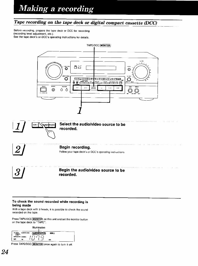
Tape recording on the tape deck or digital compact cassette (DCC)
Before recording, prepare the tape deck or DCC for recording(recording level adjustment, etc.).See the tape deck's or DCC's operating instructions for details.
TAPEIDCC_
Jr_
_R _S _AKE_
o o
I ,I _ I _1_ ;
00, , ,',
I .....I
'°'"""°'-'- 0 '_'_--_"
/
.... __"' S:/:__h.e audi0/vide0s0urce to be ...................................
I_ .......................... Begin recording: ..............................................................Follow your tape deck's or DCC's operating instructions.
.......................... Begin the audioivideo sOurce to be ...........................
recorded.
24
To check the sound recorded while recording isbeing madeWith a tape deck with 3 heads, it is possible to check the soundrecorded on the tape.
Press TAPE/DCC _ on this unit and set the monitor buttonon the tape deck to "TAPE".
Illuminates
MANUALL(_O<
Press TAPE/DeC _ once again to turn it off.

Recording £rom VCR 2 to VCR 1
Before recording, prepare the VCR (VCR 1)for recording (recor-ding level adjustment, etc.).See the VCR's operating instructions for details.
VCR (VCR 1)recording from anaudio source
Before recording, prepare the VCR (VCR1) for recording (recor-ding level adjustment, input selector setting, etc.).See the VCR's operating instructions for details.
1
_-o- _--- ............. %. ___ .-"
q _ _ I-I-I=l- -I-II _QD_
1
( I ...... i i / /_ ....)"0 _ _,. _....ri _Z
7___seiect the audio Source toi._.J be recorded.
................ Begin mCoi-ding on the VCR1 and playback the tape onthe VCR 2.
Follow your VCR's operating instruc-tions.
_l_ ................ B:gin mcoiding onthe vcRFollow your VCR's operating instruc-tions.
Begin the audio source to berecorded.
For your reference:If a laser disc player is connected to the "VCR 2" terminals, recor-ding from the laser disc player is possible by following the aboveprocedure.
25

To record picture from VCR 2 andsound from a different audio source
Before recording, prepare the VCR (VCR 1) for recording (recor-ding level adjustment, input selector setting, etc.).See the VCR's operating instructions for details.
J
_E5 I I _,' ".
1 2
Do not attempt to remove the cover(s) or repair the unit yoursell.Refer servicing to qualified personnel only.
Product information
For product service, product information or assistance with pro-duct operation, refer to the servicenter directory.
Press VCR 2.
"0'° , [_2D ®IL_sPE_.s ! / !..... _' ......
// /.....
_[_ __Seiect th; aud,o s0urce t0be recorded.
Begin recording on the VCR1.Follow your VCR's operating instruc-tions.
4 / ................Beg,.t,,e;.;,a;;_;.0;;;€;.,0berecorded and playback thetape on the VCR 2.
For your reference:If a laser disc player is connected to the "VCR 2" terminales,
recording picture from the laser disc player is possible by follow-ing the above procedures.
26

Before requesting service for this unit, check the chart below for apossible cause of the problem you are experiencing. Some simplechecks or a minor adjustment on your part may eliminate the pro-blem and restore proper operation.
tl you ale in doubt about _orvte ot the check points, or il theremedies indicated in the chart do not solve the problem, refer tothe directory of authorized service centers (enclosed with this unit)to locate a convenient service center, or consult your Technicsdealer for instructions.
(In U.S.A. consult MSC Authorized Servicenters for detailed instruc-tions.)
I Problem I Probable cause(s) Suggested remedy I
While listening to FM broadcastsAn unusual hissing noise isheard when listening to thebroadcast in stereo, but notheard when listeningmonaurally.
Noise Is excessive in bothstereo and monaural broad-casts.
The FM stereo Indicator or
the quartz lock Indicatorflickers, without completely
Illuminating.Excessive distortion in the
sound of stereo broad-casts.
A slight noise may be heard because the methodused for modulation of FM stereo broadcasts isdifferent than that used for monaural broadcasts.
Poor location andlor direction of the antenna.
Transmitting station is too far away.
Poor location andlor direction of the antenna.
Transmitting station is too far away.
Nearby building or mountain.
• Try reducing the treble sound by using the treblecontrol.
• Try changing the location, height and/or direction ofthe antenna.
• If an indoor antenna is being used, change to anoutdoor antenna.
• Try using an antenna with more elements.
• Try changing the location, height andlor direction ofthe antenna.
• If an indoor antenna is being used, change to anoutdoor antenna.
• Try using an antenna with more elements.
While listening to AM broadcastsAn unusual "beat" sound isheard.
A low-pitched "hum" soundIs heard when thebroadcast Is tuned.
A strange hissing noise Is
produced continuously orIntermittently.
Unit is being used at the same time as thetelevision set.
Interference from adjacent broadcast signal.
The AM loop antenna connection wires are tooclose to the power cord.
The power supply frequency from the power cordis modulated and heard from the speakers.
Caused by the "discharge phenomenon" and the"oscillation phenomenon" of electric appliances(such as fluorescent lights, TV, small series-typemotors, rectification equipment, etc.).
• Turn off the television set, or use this unit farther
away from it.
• Try reducing the treble sound by using the treblecontrol.
• Place the antenna connection wires and the powercord farther apart.
• Install a special outdoor antenna.
• Try placing this unit farther away from such equip-ment.
• Install noise-prevention equipment on this unit or onthe electric appliance.
While enjoying sound with DOLBY PRO LOGICThe DOLBY PRO LOGIC When the Dolby Pro Logic system is ON, both A • When the Dolby Pro Logic system is ON, A and B(SURROUND or 3 STEREO) and B speakers are turned ON. speakers cannot both be used simultaneously.Indicator will flash.
Problems noted at all timesPower will not switch ON. The power cord plug is not completely inserted.
No sound Is heard when the Connections are incomplete or incorrect to the
power Is switched ON. speaker systems, etc.The incorrect input selector has been pressed.
Sound stops during aperformance, or no soundis heard when the power isswitched ON.
(Over load indicator isIlluminated.)
• Confirm that the power cord plug is connectedcompletely.
• Check to be sure that all connection wires are
correctly connected.
• Check to be sure that the correct selector is
pressed.
• Turn on the speaker select indicator(s).
• Switch off the power, and after determining andcorrecting the cause, switch on the power onceagain.
• Use a speaker system of the proper impedancerating,
The speaker select indicators are turned off.
The protection circuitry has functioned becausethe positive and negative speaker connectionwires are "shorted", speaker systems with an
impedance less than the indicated ratedimpedance of this unit are used or under severeuse, such as loud volume, excessive power and inan excessively hot environment.
When both A and B speakers are being usedsimultaneously, the Dolby Pro Logic system isturned ON.
Speaker select indicators • When both A and B speakers are being used([A), [B|) are flashing, simultaneously, the Doiby Pro Logic system cannot
be enjoyed.
I
2?#

• AMPLIFIER SECTION
Rated minimum sine wave
RMS power output20 Hz-20 kHz both channels driven
0.05% total harmonic distortion
[SA-GX350] 100 W per channel (8 _.)
[SA-GX550] 1 10 W per channel (8 _)1 kHz continuous power output
both channels driven0.05% total harmonic distortion
[SA-GX350] 103 W per channel (8 Q)[SA-GX550] 115 W per channel (8 Q)
Total harmonic distortionrated power at 20 Hz-20 kHz 0.05% (8 Q)half power at 1 kHz 0,03% (8 Q)
Power output at the Dolby Pro Logic operationPower output (Front) 0.8% at 1 kHz
[SA-GX350] 2 x 50 W (8 Q)[SA-GX550] 2 x 75 W (8 Q)
Power output (Center) 0.8% at 1 kHz[SA-GX350] 50 W (8 £2)[SA-GX550] 75 W (8 Q)
Power output (Rear) 0.8% at 1 kHz
Dynamic headroomSMPTE intermodulatlon distortion
Frequency response
[SA-GX350] 20 W (8 Q)[SA-GX550] 30 W (8 Q)
1.2 dB (8 D)0.3% (8 £2)
PHONO RIAA standard curve +0.8 dBCD, VCR 1, VCR 2, TAPE/DCC 7 Hz-70 kHz, +3 dB
Input sensitivityPHONO 0.4 mV (3 mV, IHF '66)CD, VCR 1, VCR 2, TAPE/DCC 20 mV (200 mV, IHF '66)
SIN (IHF, A)PHONO 70 dB (80 dB, IHF '66)CD, VCR 1, VCR 2, TAPE/DCC
[SA-GX350] 75 dB (88 dB, IHF '66)[SA-GX550] 75 dB (90 dB, IHF '66)
Phono maximum Input voltage [SA-GX550 only]150 mV (IHF '66)
input ImpedancePHONO 47 k_
CD, VCR 1, VCR 2, TAPF-./DCC 22 kDTone controls
BASS 50 Hz, +10 dB to - 10 dBTREBLE 20 kHz, +10 dB to -10 dB
Loudness control (volume at -30 dB) |SA-GX550 only]50 Hz, +9 dB
Low frequency damping factor 30 (8 Q)Load Impedance
A or B [SA-GX350] 8 Q[SA-GX550] 4-8
Aand B 82
• FM TUNER SECTION
Frequency range 81.9 - 107.9 MHzSensitivity 11.2 dBf (2 pV, iHF '58)50 dB quieting sensitivity
MONO 18.3 dBf (4.5 _V, IHF '58)STEREO 38.3 dBf (45 rzV, IHF '58)
Total harmonic distortionMONO 0.2%STEREO 0.3 %
SIN
MONO 75 dBSTEREO 70 dB
Frequency response 20 Hz- 15 kHz, + 1 dB, -2 dBAlternate channel selectivity 65 dBCapture ratio 1 dBImage rejection at 98 MHz 45 dBIF rejection at 98 MHz 80 dBSpurious response rejection at 98 MHz 75 dBAM suppression 50 dBStereo separation
1 kHz 40 dB10 kHz 30 dB
Carder leak
19 kHz -35 dB38 kHz -50 dB
Antenna terminals 300 Q (balanced)75 Q (unbalanced)
• AM TUNER SECTION
Frequency range 530-1710 kHzSensitivity 20 pV, 330 IJV/mSelectivity 55 dBImage rejection at 1000 kHz 40 dBIF rejection at 1000 kHz 60 dB
• VIDEO SECTION
Output voltage at 1 V input (unbalanced)Maximum input voltage
• GENERAL
Power consumption
Power supplyDimensions ONx H x D)
Weight
[SA-GX350] 280 W, 360 VA[SA-GX550] 320 W, 430 VA
AC 120 V, 60 Hz[SA-GX350] 430 x 136 x 352 mm
(16-15/16" x 5-11/32" x 13-27132")[SA-GX550] 430 x 158 x 352 mm(16-15/16" x 6-7/32" x 13-27132")
[SA-GX350] 8.8 kg (19.4 lb.)[SA-GX550] 10.7 kg (23.5 lb.)
Notes:
1. Specifications are subject to change without notice. Weightand dimensions are approximate.
2. Total harmonic distortion is measured by the digital spectrumanalyzer.
Panasonic Company, Division ofMatsushita Electric Corporation o! AmericaOne Panasonic WaySecaucus, New Jersey 07094
Penesonlc Sales Company, Division ofMatsushita Electric of Puerto Rico, inc.San Gabriel Industrial Park65th Infantry Ave. Kin. 9.5Carolina, P.R. 00630
Panasonic Company (West) of America, Division ofMatsushita Electric Corporation of America6550 Katella Ave.Cypress, CA 90630
Matsushlta Electric of Canada Limited5770 Ambler Drive, Mississauga,Ontario L4W 2T3
Printed in Japan RQT1849-P