technicalmanual
DESCRIPTION
http://www.construmat.be/uploads/3/1/0/3/3103321/technicalmanual.pdfTRANSCRIPT


1
INTRODUCTION PAGE 2HOT AIR MANUAL WELDING PAGE 6AUTOMATIC WELDING PAGE10WELDING TRANSVERSE JOINTS PAGE13T-JOINTS – MULTIPLE WELDING SEAMS PAGE15PERIMETER FIXING PAGE16FIXING MEMBRANE TO A VERTICAL SURFACE PAGE18FIXING MEMBRANE TO A HORIZONTAL SURFACE PAGE21ACCESSORIES PAGE25INTERNAL CORNERS PAGE26EXTERNAL CORNERS PAGE33CURVED, CONICAL AND ROUND DETAILS PAGE38OUTLETS PAGE42PERIMETER EDGE FLASHING PAGE44SEAM CHECKS PAGE54DAMAGE REPAIR PAGE57INSTALLATION OF NEW MEMBRANE TO EXISTING PAGE59NOTE PAGE62
INDEX

3. EquipmentThe following is the equip-ment necessary to installFLAGON TPO membranes:•hot air manual welding
guns •20 mm nozzle (for finishing
or welding details)•40 mm nozzle (in seam welding)
•Flagofil nozzle (to weld Flagofil cord)
•28 mm Teflon roller (blue) •6 mm brass roller (to weld awkward details)
•scissors•cutter for T-joints and bevels•mill cutter for T-joints and bevels
•the welding tester (seam probe)
•automatic welding machine (type Varimat)
32
INTRODUCTION
This manual sets out theinstallation methods forFLAGON TPO membranes(polyolefin).
1. StorageRolls of FLAGON TPO mem-brane are delivered to siteon pallets.These should be stored in adry place or, if this is notpossible, protected againstdampness and exposure tofrost and snow using water-proof sheets.
2. LabellingAll FLAGON TPO membra-nes have a green label iden-tifying the membrane, itsthickness, length andwidth.All accessories used toinstall FLAGON TPO havegreen identification labelsand/or packaging.
INTRODUCTION

INTRODUCTION
54
YES
insulation layerNO SEPARATING LAYER
bitumen WITH SEPARATING LAYER
PVC membranesWITH SEPARATING LAYER
YES
NO
4. Chemical compliance *FLAGON TPO membranesare chemically compatiblewith a large range of mate-rials (refer to data sheet).
A) Insulation material It is not necessary to lay aseparation layer betweenthe waterproof membraneand most insulation boards.
B) Bitumen In the case of bitumen, laya separation layer of geo-textile before laying FLA-GON TPO.
C) PVC membranesLay a separation layer ofgeo-textile between theFLAGON TPO membraneand new PVC syntheticmembranes.
* Please contact ourTechnical Departmentwho will advise on thethe chemical complianceof FLAGON TPO mem-branes with differentmaterials
5. Cleaning welding surfaces The surface of TPO mem-branes may become elec-trostatically charged whichcan significantly increasethe deposit of dust andimpurities. Before welding,using a white cloth, cleanthe edges of the membra-ne with FLAGON TPOCLEANER.
This operation can only beavoided: 1- when welding is carried
out immediately new rolls of membrane are unrolled;
2- when automatic wel-ding is carried out usinga Varimat Leister equip-ped with a FLAG SCRA-PER NOZZLE (see step 2.1 page10).
NOTE: When the weldingsurfaces are too wet ordirty, use a new, dry, absor-bent cloth to wipe thembefore cleaning with FLA-GON TPO CLEANER.
INTRODUCTION
76
1 HOT AIR MANUAL WELDING
Setting temperature on the Triac PID
Setting temperature on the Triac S
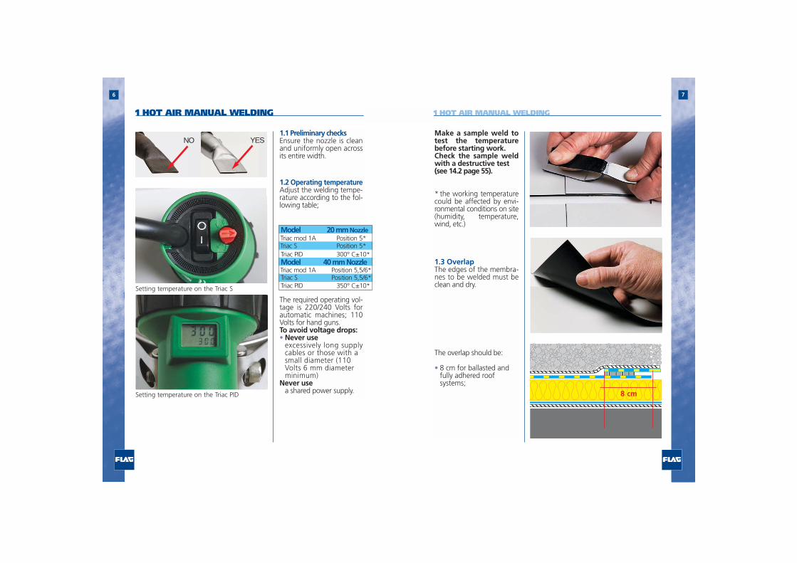
Make a sample weld totest the temperaturebefore starting work. Check the sample weldwith a destructive test (see 14.2 page 55).
* the working temperaturecould be affected by envi-ronmental conditions on site(humidity, temperature,wind, etc.)
1.3 OverlapThe edges of the membra-nes to be welded must beclean and dry.
The overlap should be:
• 8 cm for ballasted and fully adhered roof systems;
1.1 Preliminary checksEnsure the nozzle is cleanand uniformly open acrossits entire width.
1.2 Operating temperatureAdjust the welding tempe-rature according to the fol-lowing table;
The required operating vol-tage is 220/240 Volts forautomatic machines; 110Volts for hand guns.To avoid voltage drops: • Never use
excessively long supplycables or those with a small diameter (110 Volts 6 mm diameter minimum)
Never use a shared power supply. 8 cm
NO YES
1 HOT AIR MANUAL WELDING
Model 20 mm NozzleTriac mod 1A Position 5*Triac S Position 5*Triac PID 300° C±10*Model 40 mm NozzleTriac mod 1A Position 5,5/6*Triac S Position 5,5/6*Triac PID 350° C±10*

1 HOT AIR MANUAL WELDING
12 cm
98
using 40 mm nozzle
using 20 mm nozzle
1 cm
3 cm
edge of lower membrane
edge of lower membrane
• 12 cm for mechanicallyfixed roofs.
1.4 Phase 1 – spot weldingSpot-weld the overlap,about every 40 cm.Distance the spot weldingfrom the edge of the lowersheet, by:
• 1 cm (using the 40 mmnozzle)
• 3 cm (using the 20 mmnozzle)
1.5 Phase 2 - pre-weldingWeld the rear overlap areaso that the following ope-nings remain for the fini-shing weld: • 4 cm (using the 40 mm
nozzle);
• 3 cm (using the 20 mmnozzle)
Position the nozzlebetween the two edges atan angle of 45° to the wel-ding line.Roll at a distance of about1 cm from the nozzle
1.6 Phase 3 - weldingCarry out the weld at theedge of the upper layer.Position the nozzlebetween the two edges atan angle of 45° degrees tothe welding line.Roll at a distance of about1 cm from the nozzle.
4 cm
using 40 mm nozzle
3 cm
using 20 mm nozzle
1 HOT AIR MANUAL WELDING
1110
2 AUTOMATIC WELDING
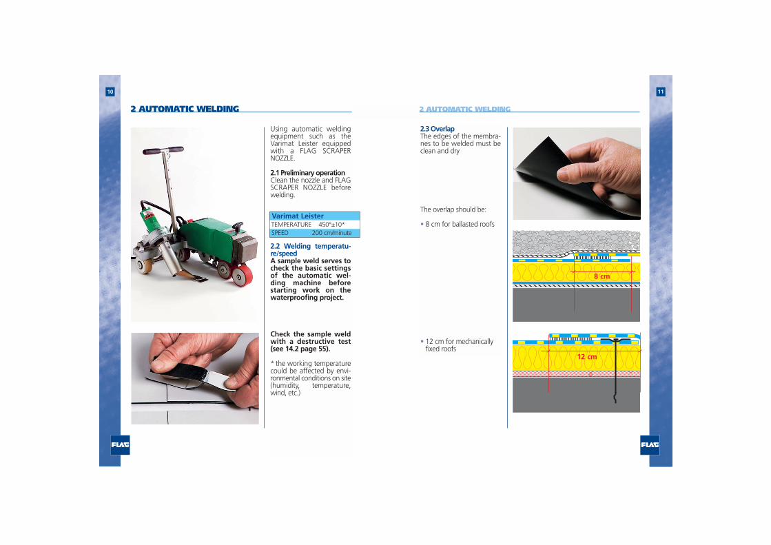
Using automatic weldingequipment such as theVarimat Leister equippedwith a FLAG SCRAPERNOZZLE.
2.1 Preliminary operationClean the nozzle and FLAGSCRAPER NOZZLE beforewelding.
2.2 Welding temperatu-re/speedA sample weld serves tocheck the basic settingsof the automatic wel-ding machine beforestarting work on thewaterproofing project.
Check the sample weldwith a destructive test(see 14.2 page 55).
* the working temperaturecould be affected by envi-ronmental conditions on site(humidity, temperature,wind, etc.)
Varimat LeisterTEMPERATURE 450°±10*SPEED 200 cm/minute
2.3 OverlapThe edges of the membra-nes to be welded must beclean and dry
The overlap should be:
• 8 cm for ballasted roofs
• 12 cm for mechanically fixed roofs
8 cm
12 cm
2 AUTOMATIC WELDING

13
2.4 Use of Flag scrapernozzleThis scrapes the surface ofthe FLAGON TPO membra-ne enhancing welding andavoiding the necessity ofcleaning.
Using a screwdriver, insertthe FLAG SCRAPER NOZZLEbetween the layers to bewelded.
Carry out the welding..
12
Round off sharp edges withscissors.When possible, avoid crea-ting multiple cross jointswith more than threesheets.
For this purpose:a) position two or moresheets perfectly parallel andaligned. Weld a third sheetor strip (min. 20 cm) tran-sversally (90°) to previouslyinstalled sheets;
2 AUTOMATIC WELDING 3 WELDING TRANSVERSE JOINTS

3 WELDING TRANSVERSE JOINTS
1514
b) stagger the joints
4 T-JOINTS – MULTIPLE WELDING
At “T-joints” (e.g. at the trailingedges of sheets, and wheninstalling any prefabricatedFLAGON TPO elements):
a) chamfer the weldingseam edge with the mill orchamfer tool.
This operation removes thedifference in height resul-ting from the overlappingof several waterproofingsheets and allows adequatecleaning of the seam priorto welding.
b) cut a circle of membrane(diameter approx. 15 cm)and weld over the chamfe-red T-joint.
c) Spot-weld, pre-weld andweld.
15 cm
chamfering
second weld
first weld
1716
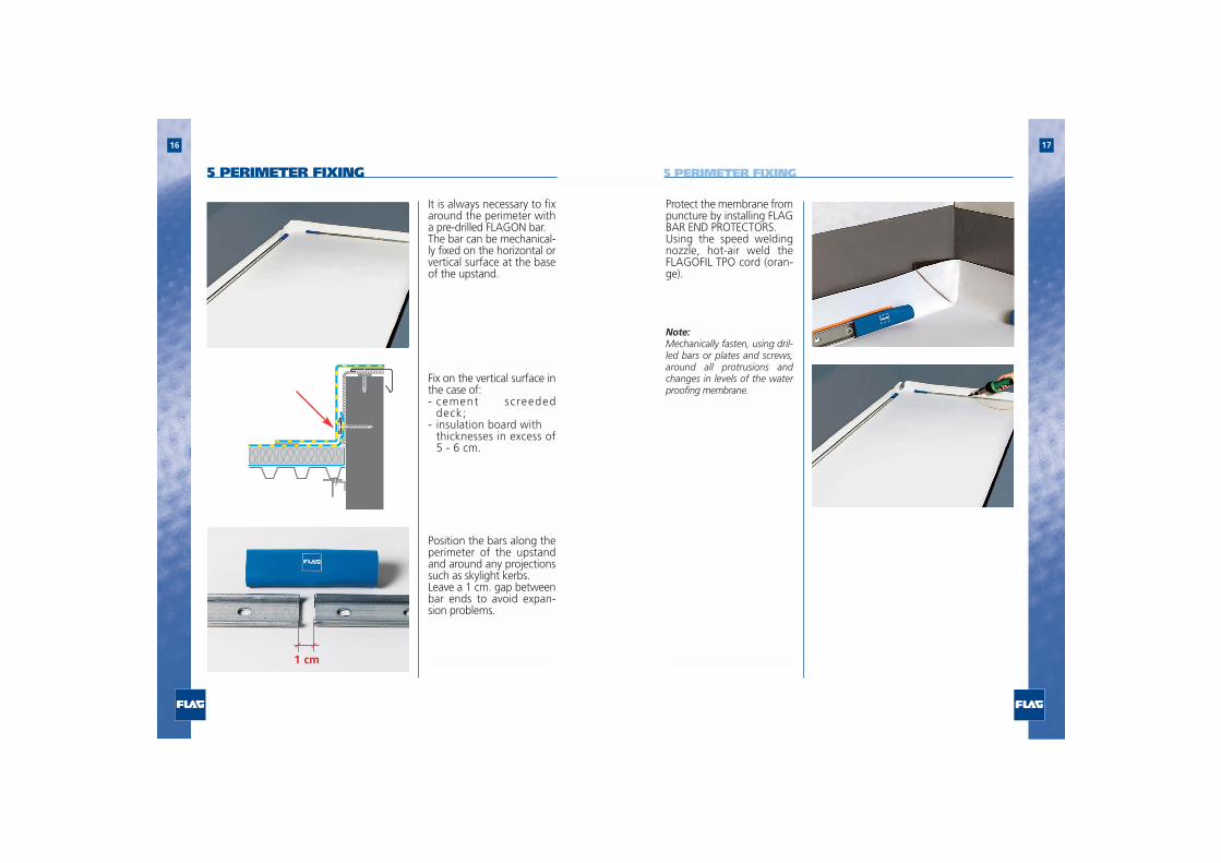
1 cm
It is always necessary to fixaround the perimeter witha pre-drilled FLAGON bar.The bar can be mechanical-ly fixed on the horizontal orvertical surface at the baseof the upstand.
Fix on the vertical surface inthe case of:- cement screeded
deck;- insulation board with
thicknesses in excess of5 - 6 cm.
Position the bars along theperimeter of the upstandand around any projectionssuch as skylight kerbs.Leave a 1 cm. gap betweenbar ends to avoid expan-sion problems.
Protect the membrane frompuncture by installing FLAGBAR END PROTECTORS.Using the speed weldingnozzle, hot-air weld theFLAGOFIL TPO cord (oran-ge).
Note:Mechanically fasten, using dril-led bars or plates and screws,around all protrusions andchanges in levels of the waterproofing membrane.
5 PERIMETER FIXING 5 PERIMETER FIXING
1918
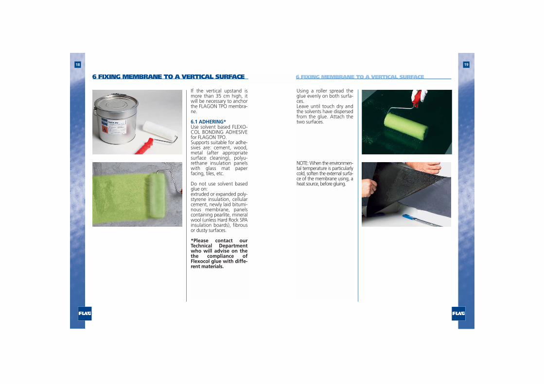
Using a roller spread theglue evenly on both surfa-ces. Leave until touch dry andthe solvents have dispersedfrom the glue. Attach thetwo surfaces.
NOTE: When the environmen-tal temperature is particularlycold, soften the external surfa-ce of the membrane using, aheat source, before gluing.
If the vertical upstand ismore than 35 cm high, itwill be necessary to anchorthe FLAGON TPO membra-ne.
6.1 ADHERING*Use solvent based FLEXO-COL BONDING ADHESIVEfor FLAGON TPO.Supports suitable for adhe-sives are: cement, wood,metal (after appropriatesurface cleaning), polyu-rethane insulation panelswith glass mat paperfacing, tiles, etc.
Do not use solvent basedglue on: extruded or expanded poly-styrene insulation, cellularcement, newly laid bitumi-nous membrane, panelscontaining pearlite, mineralwool (unless Hard Rock SPAinsulation boards), fibrousor dusty surfaces.
*Please contact ourTechnical Departmentwho will advise on thethe compliance ofFlexocol glue with diffe-rent materials.
6 FIXING MEMBRANE TO A VERTICAL SURFACE 6 FIXING MEMBRANE TO A VERTICAL SURFACE

21
6.2 Mechanical fixing Fixings should be positio-ned 6 cm from the edgeand a maximum 25 cmapart. (Fixing centres willvary according to the buil-ding height and exposure.Please consulte the FLAGTechnical Department forfixing design requirements.)
Overlap the fixing line by 12cm with the subsequentsheet.Spot-weld, pre-weld, andweld.
20
6 cm
25 cm
7 FIXING MEMBRANE TO HORIZONTAL SURFACE7.1- Fully adhering (flee-ce-backed FLAGON TPOmembrane)For fully adhering, useFlexocol A89 glue. Usingthe spatula supplied, spreadthe glue onto the suppor-ting surface. (Refer to glueinstallation data sheet.)Spot-weld, pre-weld, andweld.
NOTE: Avoid contaminatingthe welding edge of themembrane with glue. Any glue spots or residuecan be removed withalcohol or acetone and aclean cloth.
7.2 Mechanical fixingNOTE: When using trape-zoidal metal decks themembrane must be laid atright angles to the deckdirection. With concrete decking themembrane can be laid inany direction.
There are two methodsmechanically fixing themembrane:
a) Fixing plates and screwsb) Fixing with FLAG BARS
12 cm
6 FIXING MEMBRANE TO A VERTICAL SURFACE

23
b) Fixing with FLAGBARS FLAG BARS are installed atpre-determined centresaccording to the wind loadrequiriments of the localarea and the building hei-ght.
IMPORTANT: The insulationboards must be fixed inde-pendently to the membra-ne.
FLAG BAR ends should beinstalled with a 1 cmexpansion gap betweeneach bar.
FLAG BAR END PROTEC-TORS must be installed toall bar ends to preventpuncturing during move-ment and stress.Hot air weld the overlapusing manual or automaticmethods.
Install the bar system, withbar end protectors, at thepre-determined centresrecommended by the FLAGTechnical Department.
Hot air weld 20 cm mini-mum strip over the fixingbar as shown in the dia-gram.*.
22
a) Fixing plates andscrews.Fixing is carried out usingproprietory fixing plates andscrews along the edge ofthe membrane as shown.Fixing centres are determi-ned by the building heightand the topography of thearea when subjected towind.*
The adjoining membraneoverlaps the fixed sheet by aminimum 12 cm encapsula-ting the fixing line.Weld the membranetogether, using manual orautomatic methods, to forma homogenous seam.
In areas of high wind expo-sure it may be necessary toincrease the fixing centres inthe perimeter and cornerzones of the building. This iseasily achieved by insertinga line of fixing long the cen-tre of the installed membra-ne and then using a mini-mum 20 cm wide strip weldas shown in the diagram. This same method can alsobe carried out when usingpre-drilled FLAG BARS inlieu of fixing plates andscrews.
* Please contact the FLAGTechnical Departmentregarding fixing design cal-culations.
12 cm
8 cm
1 cm
7 FIXING MEMBRANE TO HORIZONTAL SURFACE7 FIXING MEMBRANE TO HORIZONTAL SURFACE

2524
To improve installationtimes the FLAGON TPOroofing system has a widerange of hot air weldableaccessories that includevents, outlets, scuppersand internal and externalcorners.
Consideration must begiven to drainage of waterfrom the roof. FLAG BARSshould be installed toallow free flow of waterfrom the roof area.
FLAG BAR END PROTEC-TORS must be installedwhen using the FLAG BARsystem to avoid damage tothe waterproofing mem-brane when subjected tomovement stresses..
* Please contact the FLAGTechnical Departmentregarding fixing designcalculations.
7 FIXING MEMBRANE TO HORIZONTAL SURFACE 8 ACCESSORIES

27
9.2 Prefab internal corner Measure and cut the mem-brane to fit the upstandplus an extra 12 cm (mini-mum) for welding on thehorizontal surface. Fix thismembrane to the upstandby gluing or spot-welding.
Dress the excess into thecorner and cut it up to 2 cmfrom the edge.
26
9.1 Horizontal pre-fabri-cated internal cornerPosition the FLAGON TPOmembrane on the horizon-tal surface fixing it at theperimeter with pre-drilledbar. Locate fixing bars 15cm from the corner, protec-ting the ends with FLAGBAR END PROTECTOR.
Fold the excess membranetowards the wall.
Using hot air seal and weldthe “pocket” to the verticalsurface.
9 INTERNAL CORNERS
15 cm15 cm
45°
12 cm
12 cm
2 cm
9 INTERNAL CORNERS

29
Chamfer the welding seamedge with the mill or cham-fer tool.
Spot-weld, pre-weld andweld the overlap on theupper edge (B) of the hori-zontal surface. .
28
Overlap the two edges ofmembrane and cut theexcess material up to 2 cmfrom the edge as illustratedin the picture.
Spot-weld, pre-weld andweld the overlap on onlythe lower edge (A) of thehorizontal surface
2 cm
9 INTERNAL CORNERS
A
B
9 INTERNAL CORNERS

31
9.3 Internal corner withvertical creaseApply FLAG BONDINGADHESIVE to the internalupstand and FLAGON pre-formed flashing leaving a 12cm strip for hot air weldingto the main field sheet.
Bond the membrane to theupstand starting at the topedge and working down tothe base.
Cut and glue the secondFLAG flashing strip on theupstand, leaving 12 cmwidth for welding on to thehorizontal surface.
30
After chamfering the seamedge, spot weld the FLA-GON TPO prefab corner inposition.
Working from the centre ofthe corner outwards, pre-pare a pre-welding line, setback 3 cm from the borderof the corner.
Using the 20 mm nozzle,weld the prefab corner intoposition.
Note:Always clean the surfaces to bewelded with a clean cloth andFLAGON TPO CLEANER.
presaldatura
saldatura
3 cm
9 INTERNAL CORNERS 9 INTERNAL CORNERS

3332
Spot weld in position asindicated. Then fold themembrane to form an upri-ght crease.Weld the strip to the firstFLAG flashing and weld thecrease together. Fold thecrease back on to the verti-cal face. Spot weld, pre-weld and weld.
Close the bend on the ver-tical wall by spot-welding,pre-welding and welding.
10.1 Horizontal surface Position the FLAGON TPOmembrane on the horizon-tal surface fixing it at theperimeter with pre-drilledbar. Locate fixing bars 15cm from the corner, protec-ting the ends with FLAGBAR END PROTECTORS.
10.2 Prefab external cornerMeasure and cut the mem-brane to fit the upstandplus an extra 12 cm (mini-mum) for welding to thehorizontal surface.
Apply FLAG BONDINGADHESIVE to the upstandface and to the FLAG mem-brane. Allow the glue tobecome tack dry. Thenbond together on one faceof the external corner to becovered, as shown.
Make a cut in line with thecorner.
Turn the membrane alongthe adjacent wall and bondin position.On the horizontal surface,spot-weld, pre-weld andweld the membrane alongboth sides.
45°
10 EXTERNAL CORNERS9 INTERNAL CORNERS

35
Note:Always clean the surfaces to bewelded with a clean cloth andFLAGON TPO CLEANER.
34
Chamfer the edge forabout 5 cm as illustrated.
Position the prefab FLA-GON TPO external corner.
Spot-weld, pre-weld andweld working from thecentre of the corneroutwards.
5 cm
5 cm
CHAMFERING LINE
10 EXTERNAL CORNERS 10 EXTERNAL CORNERS
3736
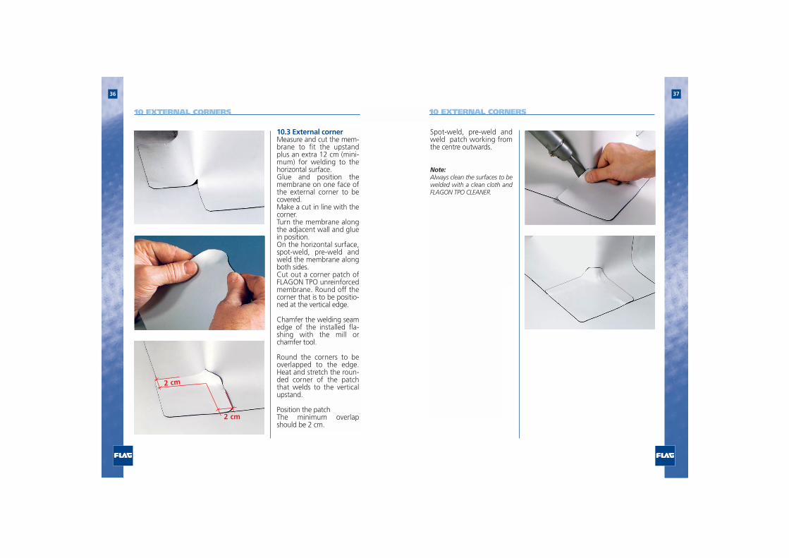
Spot-weld, pre-weld andweld patch working fromthe centre outwards.
Note:Always clean the surfaces to bewelded with a clean cloth andFLAGON TPO CLEANER.
10.3 External corner Measure and cut the mem-brane to fit the upstandplus an extra 12 cm (mini-mum) for welding to thehorizontal surface. Glue and position themembrane on one face ofthe external corner to becovered.Make a cut in line with thecorner.Turn the membrane alongthe adjacent wall and gluein position.On the horizontal surface,spot-weld, pre-weld andweld the membrane alongboth sides.Cut out a corner patch ofFLAGON TPO unreinforcedmembrane. Round off thecorner that is to be positio-ned at the vertical edge.
Chamfer the welding seamedge of the installed fla-shing with the mill orchamfer tool.
Round the corners to beoverlapped to the edge.Heat and stretch the roun-ded corner of the patchthat welds to the verticalupstand.
Position the patchThe minimum overlapshould be 2 cm.
2 cm
10 EXTERNAL CORNERS 10 EXTERNAL CORNERS
2 cm

3938
Replace the cylinder andweld to the newly formedupstand of the base fla-shing.
Note:Always clean the surfaces to bewelded with a clean cloth andFLAGON TPO CLEANER.
11.1 Extractor vents,pipes etc.Cut out a square ofunre inforced FLAGONTPO membrane andround off the cornerswith scissors. .
Cut a hole 1 cm smallerthan the pipe size in themiddle of the square.Carefully heat around thehole and stretch the mem-brane over the pipe crea-ting an upstand rim at thebase of the pipe. Spot weld, pre-weld andweld to the main fieldsheet.
Cut a strip of unreinforcedFLAGON TPO plus an extra3 cm for vertical welding asillustrated.The height of the stripshould equal the height ofthe cylinder body plus anextra 3 cm for welding tothe horizontal surface.Spot-weld, pre-weld andweld the vertical seam.
Remove the resulting cylin-der and manually spreadthe excess for welding ontothe horizontal surface.
11 CURVED, CONICAL AND ROUNDED DETAILS 11 CURVED, CONICAL AND ROUNDED DETAILS
3 cm
4140
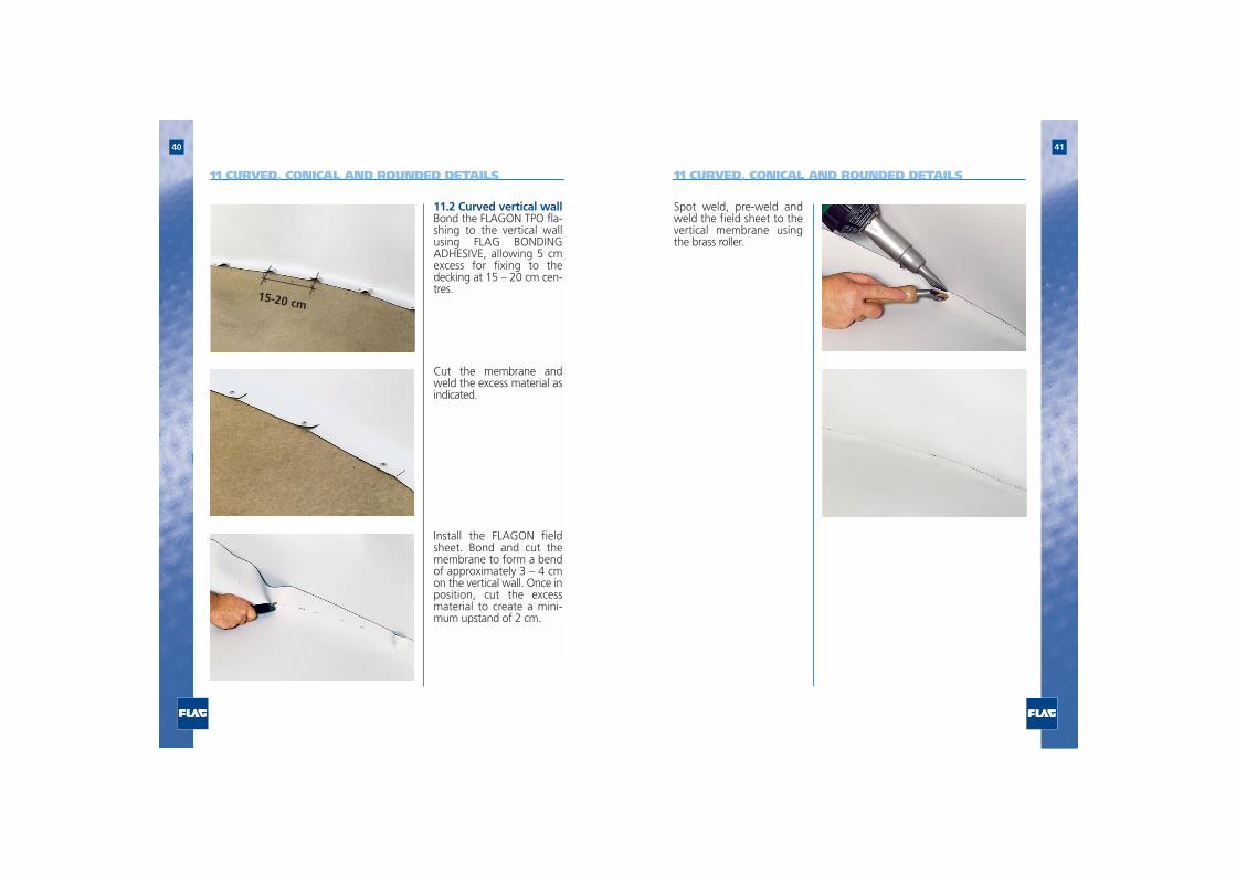
Spot weld, pre-weld andweld the field sheet to thevertical membrane usingthe brass roller.
11.2 Curved vertical wallBond the FLAGON TPO fla-shing to the vertical wallusing FLAG BONDINGADHESIVE, allowing 5 cmexcess for fixing to thedecking at 15 – 20 cm cen-tres.
Cut the membrane andweld the excess material asindicated.
Install the FLAGON fieldsheet. Bond and cut themembrane to form a bendof approximately 3 – 4 cmon the vertical wall. Once inposition, cut the excessmaterial to create a mini-mum upstand of 2 cm.
11 CURVED, CONICAL AND ROUNDED DETAILS 11 CURVED, CONICAL AND ROUNDED DETAILS
15-20 cm

4342
Insert the FLAGON TPOpre-fabricated outlet..
Note:Always clean the surfaces to bewelded with a clean cloth andFLAGON TPO CLEANER.
Spot-weld, pre-weld andweld the flange of theFLAG outlet to the mainfield sheet.
weld
pre-weld
Only use outlets from theFLAGON TPO range.Cut a hole in the roof mem-brane to correspond withthe downpipe.
Mechanically fix the mem-brane around the outlet tothe decking withy fixingplates and screws.
12 OUTLETS12 OUTLETS

4544
fixings will be required.13.1 -Flashing on internalcornerMark the cutting line, bothhorizontally and vertically.
Squeeze the drip near thecutting line to identify thedesired cutting point
Cut on the horizontal levelat about 30° with reference1 cm
Install FLAG metal lami-nated flashings inconjunction with a neo-prene or butyl tape sea-ling strip leaving a 1 cmgap for expansion/con-traction.
Fix the flashing with expan-sion nails or counter sunkscrews.
Warning: always ensu-re the perimeter edgecan accommodatefixings to withstandthe anticipated windloadings
Cover the expansion jointwith a 2 cm masking tapeprior to welding a 8 cmwide strip over the joint asillustrated.
To allow for movement onlyweld either side of the stripto a maximum of 2 cm.For ease when welding themembrane to the top surfa-ce of the FLAGMETAL allowa 1 cm gap from the frontface.
For flashings with facedepths greater than 5 cminternal support metalbutt straps or face
13 PERIMETER EDGE FLASHING
longitudinal joint
8 cm
1 cm
2 cm2 cm
8 cm
13 PERIMETER EDGE FLASHING
30°

4746
to the marked line.Bend to form a 90° cornerand trim the overlap at 45°as illustrated
After positioning the neo-prene or butyl sealing strip,mechanically fix the prepa-red flashing to the perime-ter edgeCut and weld a strip ofmembrane over the newjoint.
45°
13 PERIMETER EDGE FLASHING 13 PERIMETER EDGE FLASHING
Weld the waterproof mem-brane to the flashing.Chamfer the welding edge.
Round the corners of a pie-ce of FLAGON TPOunreinforced membraneallowing a 2 cm excess foroverlapping and welding.

4948
Heat and stretch the inter-nal corner of the patch.
Spot-weld, pre-weld andweld the patch onto thecorner.
13 PERIMETER EDGE FLASHING
13.2-Flashing on externalcornerMark the cutting line, bothhorizontally and vertically.
Squeeze the drip near thecutting line to identify thedesired cutting point.
13 PERIMETER EDGE FLASHING

5150
Cut the horizontal surfacefollowing the cutting line.
Open the flashing.After installing the neopre-ne/butyl sealing strip,mechanically fix the fla-shing to the perimeteredge.
Round the corners of asquare patch of FLAGONTPO unreinforced membra-ne allowing a 2 cm excessfor overlapping and wel-ding.Heat and stretch the inter-nal corner of the patch
13 PERIMETER EDGE FLASHING
1 cm
Position the patch over thecorner area. Spot-weld,pre-weld and weld to themetal plate.
Spot-weld the flashingonto the profile starting 1cm from the edge. Theexcess membrane fromthe vertical surface willform a pocket at the cor-ner edge.
13 PERIMETER EDGE FLASHING

5352
Cut the pocket up to 2 cmfrom the corner edge.
Trim the triangle of excessmaterial.Chamfer the edges.
13 PERIMETER EDGE FLASHING
Spot-weld, pre-weld, andweld, onto the horizontalsurface of the flashing.
Note:Always clean the surfaces to bewelded with a clean cloth andFLAGON TPO CLEANER.
13 PERIMETER EDGE FLASHING

5554
14.1 Non-destructivecontrol Carry out the test, using thewelding tester (seam probe)on cooled material.Pass the seam probe alongthe welding line, exertingsufficient pressure to iden-tify defective seams
In the case of defectiveseams, follow the seam clea-ning procedure prior to re-welding as necessary. Inextreme situations, it isnecessary to weld a 15 – 20cm strip over the existingwelding line after cleaning.When using automatic wel-ding machines for this pro-cess use the FLAG SCRAPERNOZZLE. (see point 15).
14 SEAM CHECKS
1 cm 1 cm
14.2 Destructive controlCut out a 1 cm section ofthe welded membrane.
Apply pressure to the weldby pulling on the two endsof the sheet as illustrated inthe picture.
14 SEAM CHECKS

5756
The membrane must failoutside the welding seam.
This control must alwaysbe carried out each dayon a sample weld beforethe installation of thewaterproof membranecommences.
Note: The test, althoughmanually performed onsite, is based on the provi-sions set forth by theUEAtc Directive
Should accidental damageoccur after installation,repairs are simple.
Cut a patch of FLAGON tocompletely cover the cutand round the corners withscissors.
Trace the circumference ofthe patch onto the surface
Scrape the surface of thewaterproof membrane.
14 SEAM CHECKS 15 DAMAGE REPAIR

5958
Clean the surface of themembrane with a newcloth and FLAGON TPOCLEANER.
Spot-weld, pre-weld andweld the patch in place.
a) Manual weldingPosition the new FLAGONTPO on the existing mem-brane.Mark the overlap line.
Bend back the new mate-rial.Clean the surface of the exi-sting membrane with anabrasive disk.
Clean the surface to bewelded with FLAGON TPOCLEANER using a clean drycloth.
16 INSTALLATION OF NEW MEMBRANE TO EXISTING
15 DAMAGE REPAIR

6160
Re-align the new material.Spot-weld, pre-weld andweld to the existing mem-brane.
b) automatic weldingwith Varimat welder Position the new FLAGONTPO on the existing mem-brane. Mark the overlapline.Bend back the new mate-rial.
Clean with a cloth and FLA-GON TPO CLEANER.
Re-align the new materialand weld using a Varimatautomatic welder fittedwith a FLAG SCRAPER
16 INSTALLATION OF NEW MEMBRANE TO EXISTING 16 INSTALLATION OF NEW MEMBRANE TO EXISTING

62
Flag S.p.A. has the right to modify without previous notice text, images or
outlines contained in this manual, whenever innovation of the production
methods or in the application of the materials should occur.
Flag S.p.A. guarantee exclusively refers to materials and accessories produ-
ced and supplied by Flag itself. The installation of membranes produced by
FLAG S.p.A; must be performed by specialised contractors whose operatives
have undergone FLAG TPO training.
Please contact FLAG S.p.A.’s Technical Department for guidance for any spe-
cific matters not covered in this manual.
NOTE