technical specifications txdot item 300...
TRANSCRIPT
CITY OF ST. HEDWIG CRACK FILL & POTHOLE REPAIR JANUARY 2015 IMPROVEMENTS
TECHNICAL SPECIFICATIONS
TXDOT ITEM 300 – ASPHALTS, OILS AND EMULSIONS
TXDOT ITEM 302 – AGGREGATES FOR SURFACE TREATMENTS
TXDOT ITEM 314 – EMULSIFIED ASPHALT TREATMENT
TXDOT ITEM 340 – DENSE-GRADED HOT-MIX ASPHALT (SMALL QUANTITY)
TXDOT ITEM 700 – POTHOLE REPAIR
TXDOT ITEM 712 – CLEANING AND SEALING JOINTS AND CRACKS (ASPHALT CONCRETE)
300
172
Item 300
Asphalts, Oils, and Emulsions
1. DESCRIPTION
Provide asphalt cements, cutback and emulsified asphalts, performance-graded asphalt binders, and other miscellaneous asphalt materials as specified on the plans.
2. MATERIALS
Provide asphalt materials that meet the stated requirements when tested in accordance with the referenced Department, AASHTO, and ASTM test methods. Provide asphalt materials that have been preapproved for use by the Construction Division in accordance with Tex-545-C, “Asphalt Binder Quality Program,” unless otherwise shown on the plans.
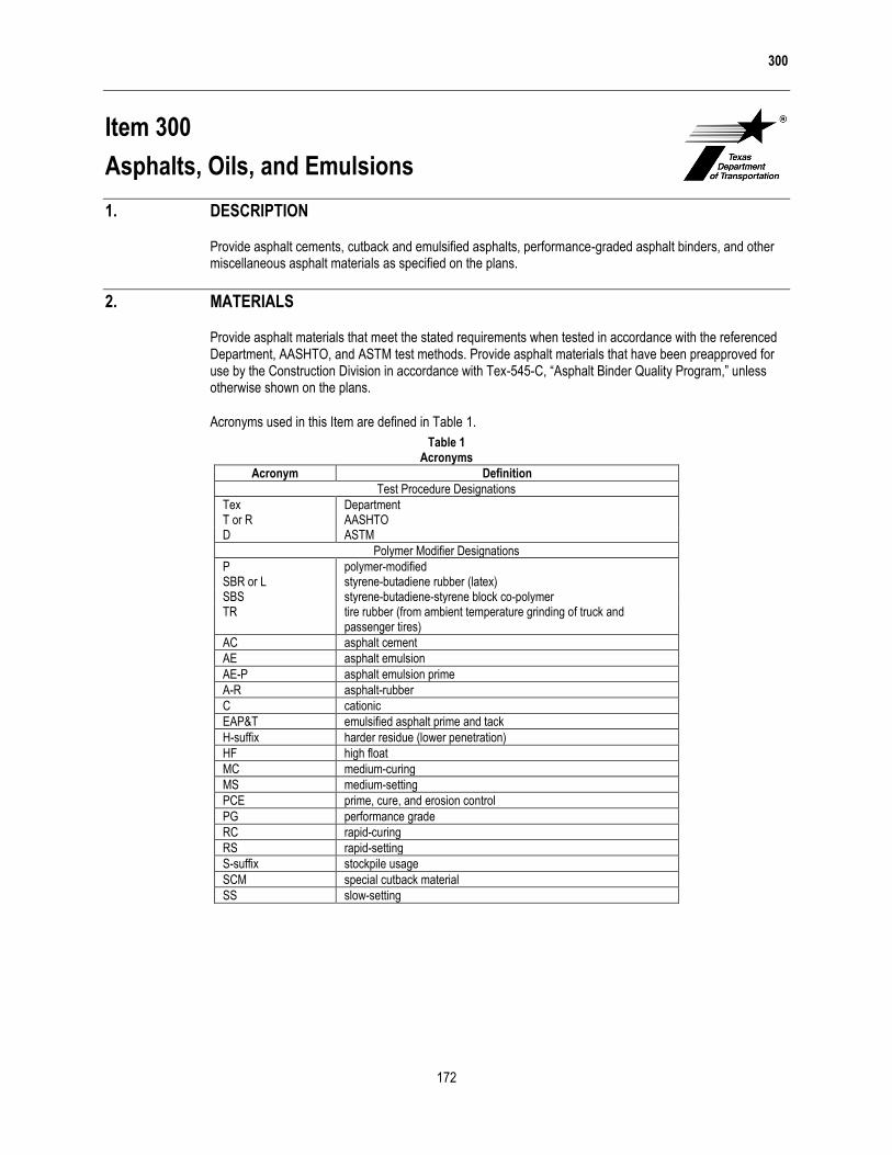
Acronyms used in this Item are defined in Table 1.
Table 1 Acronyms
Acronym Definition
Test Procedure Designations
Tex Department T or R AASHTO D ASTM
Polymer Modifier Designations
P polymer-modified SBR or L styrene-butadiene rubber (latex) SBS styrene-butadiene-styrene block co-polymer TR tire rubber (from ambient temperature grinding of truck and
passenger tires)
AC asphalt cement
AE asphalt emulsion
AE-P asphalt emulsion prime
A-R asphalt-rubber
C cationic
EAP&T emulsified asphalt prime and tack
H-suffix harder residue (lower penetration)
HF high float
MC medium-curing
MS medium-setting
PCE prime, cure, and erosion control
PG performance grade
RC rapid-curing
RS rapid-setting
S-suffix stockpile usage
SCM special cutback material
SS slow-setting

300
173
2.1. Asphalt Cement. Provide asphalt cement that is homogeneous, water-free, and nonfoaming when heated to 347°F, and meets the requirements in Table 2.
Table 2 Asphalt Cement
Property Test Procedure
Viscosity Grade
AC-0.6 AC-1.5 AC-3 AC-5 AC-10
Min Max Min Max Min Max Min Max Min Max
Viscosity T 202 140°F, poise 40 80 100 200 250 350 400 600 800 1,200 275°F, poise 0.4 – 0.7 – 1.1 – 1.4 – 1.9 –
Penetration, 77°F, 100g, 5 sec.
T 49 350 – 250 – 210 – 135 – 85 –
Flash point, C.O.C., °F T 48 425 – 425 – 425 – 425 – 450 –
Solubility in trichloroethylene, % T 44 99.0 – 99.0 – 99.0 – 99.0 – 99.0 –
Spot test Tex-509-C Neg. Neg. Neg. Neg. Neg.
Tests on residue from Thin-Film Oven Test: T 179
Viscosity, 140°F, poise T 202 – 180 – 450 – 900 – 1,500 – 3,000 Ductility,1 77°F
T 51 100 – 100 – 100 – 100 – 100 – 5 cm/min., cm
1. If AC-0.6 or AC-1.5 ductility at 77°F is less than 100 cm, material is acceptable if ductility at 60°F is more than 100 cm.
2.2. Polymer-Modified Asphalt Cement. Provide polymer-modified asphalt cement that is smooth, homogeneous, and meets the requirements of Table 3. Supply samples of the base asphalt cement and polymer additives if requested.
Table 3 Polymer-Modified Asphalt Cement
Property Test
Procedure
Polymer-Modified Viscosity Grade
AC-5 w/2% SBR
AC-10 w/2% SBR
AC-15P AC-20XP AC-10-2TR AC-20-5TR
Min Max Min Max Min Max Min Max Min Max Min Max
Polymer SBR SBR SBS SBS TR TR
Polymer content, % (solids basis) Tex-533-C 2.0 – 2.0 – 3.0 – – – 2.0 – 5.0 –
Dynamic shear, G*/sin , 64°C, 10 rad/s, kPa T 315 – – – – – –
1.0
– – – 1.0 –
Dynamic shear, G*/sin , 58°C, 10 rad/s, kPa T 315 – – – – – –
– – 1.0 – – –
Viscosity 140°F, poise T 202 700 – 1,300 – 1,500 – 2,000 – 1,000 – 2,000 – 275°F, poise T 202 – 7.0 – 8.0 – 8.0 – – – 8.0 – 10.0
Penetration, 77°F, 100 g, 5 sec. T 49 120 – 80 – 100 150 75 115 95 130 75 115
Ductility, 5cm/min., 39.2°F, cm T 51 70 – 60 – – – – – – – – –
Elastic recovery, 50°F, % Tex-539-C – – – – 55 – 55 – 30 – 55 –
Softening point, °F T 53 – – – – – – 120 – 110 – 120 –
Polymer separation, 48 hr. Tex-540-C None None None None None None
Flash point, C.O.C., °F T 48 425 – 425 – 425 – 425 – 425 – 425 –
Tests on residue from RTFOT aging and pressure aging:
Tex-541-C and R 28
Creep stiffness T 313 S, -18°C, MPa – – – – – 300 – 300 – 300 – 300 m-value, -18°C – – – – 0.300 – 0.300 – 0.300 – 0.300 –
300
174
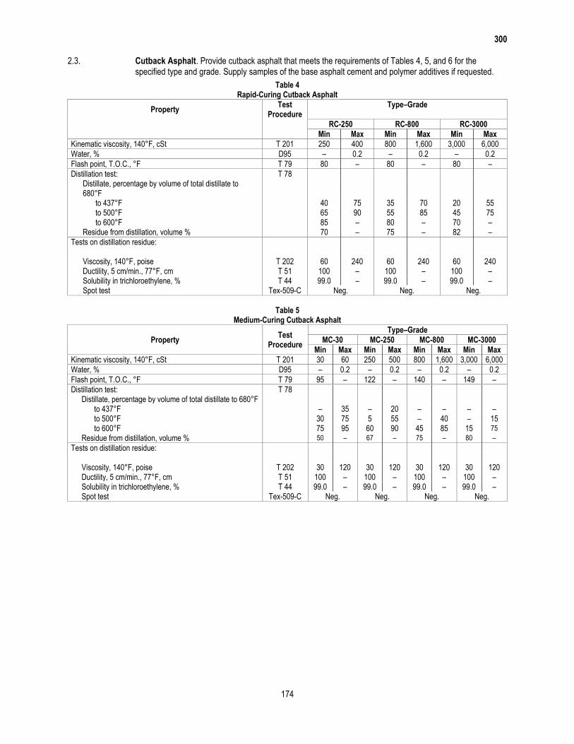
2.3. Cutback Asphalt. Provide cutback asphalt that meets the requirements of Tables 4, 5, and 6 for the specified type and grade. Supply samples of the base asphalt cement and polymer additives if requested.
Table 4 Rapid-Curing Cutback Asphalt
Property Test
Procedure Type–Grade
RC-250 RC-800 RC-3000
Min Max Min Max Min Max
Kinematic viscosity, 140°F, cSt T 201 250 400 800 1,600 3,000 6,000
Water, % D95 – 0.2 – 0.2 – 0.2
Flash point, T.O.C., °F T 79 80 – 80 – 80 –
Distillation test: T 78 Distillate, percentage by volume of total distillate to
680°F to 437°F 40 75 35 70 20 55 to 500°F 65 90 55 85 45 75 to 600°F 85 – 80 – 70 – Residue from distillation, volume % 70 – 75 – 82 –
Tests on distillation residue: Viscosity, 140°F, poise T 202 60 240 60 240 60 240 Ductility, 5 cm/min., 77°F, cm T 51 100 – 100 – 100 – Solubility in trichloroethylene, % T 44 99.0 – 99.0 – 99.0 – Spot test Tex-509-C Neg. Neg. Neg.
Table 5
Medium-Curing Cutback Asphalt
Property Test
Procedure
Type–Grade
MC-30 MC-250 MC-800 MC-3000
Min Max Min Max Min Max Min Max
Kinematic viscosity, 140°F, cSt T 201 30 60 250 500 800 1,600 3,000 6,000
Water, % D95 – 0.2 – 0.2 – 0.2 – 0.2
Flash point, T.O.C., °F T 79 95 – 122 – 140 – 149 –
Distillation test: T 78 Distillate, percentage by volume of total distillate to 680°F to 437°F – 35 – 20 – – – – to 500°F 30 75 5 55 – 40 – 15 to 600°F 75 95 60 90 45 85 15 75
Residue from distillation, volume % 50 – 67 – 75 – 80 –
Tests on distillation residue: Viscosity, 140°F, poise T 202 30 120 30 120 30 120 30 120 Ductility, 5 cm/min., 77°F, cm T 51 100 – 100 – 100 – 100 – Solubility in trichloroethylene, % T 44 99.0 – 99.0 – 99.0 – 99.0 – Spot test Tex-509-C Neg. Neg. Neg. Neg.
300
175
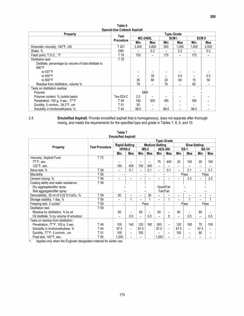
Table 6 Special-Use Cutback Asphalt
Property Test
Procedure
Type–Grade
MC-2400L SCM I SCM II
Min Max Min Max Min Max
Kinematic viscosity, 140°F, cSt T 201 2,400 4,800 500 1,000 1,000 2,000
Water, % D95 – 0.2 – 0.2 – 0.2
Flash point, T.O.C., °F T 79 150 – 175 – 175 –
Distillation test: T 78 Distillate, percentage by volume of total distillate to
680°F
to 437°F – – – – – – to 500°F – 35 – 0.5 – 0.5 to 600°F 35 80 20 60 15 50 Residue from distillation, volume % 78 – 76 – 82 –
Tests on distillation residue: Polymer SBR – – Polymer content, % (solids basis) Tex-533-C 2.0 – – – – – Penetration, 100 g, 5 sec., 77°F T 49 150 300 180 – 180 – Ductility, 5 cm/min., 39.2°F, cm T 51 50 – – – – – Solubility in trichloroethylene, % T 44 99.0 – 99.0 – 99.0 –
2.4. Emulsified Asphalt. Provide emulsified asphalt that is homogeneous, does not separate after thorough mixing, and meets the requirements for the specified type and grade in Tables 7, 8, 9, and 10.
Table 7
Emulsified Asphalt
Property Test Procedure
Type–Grade
Rapid-Setting Medium-Setting Slow-Setting
HFRS-2 MS-2 AES-300 SS-1 SS-1H
Min Max Min Max Min Max Min Max Min Max
Viscosity, Saybolt Furol T 72 77°F, sec. – – – – 75 400 20 100 20 100 122°F, sec. 150 400 100 300 – – – – – –
Sieve test, % T 59 – 0.1 – 0.1 – 0.1 – 0.1 – 0.1
Miscibility T 59 – – – Pass Pass
Cement mixing, % T 59 – – – – – – – 2.0 – 2.0
Coating ability and water resistance: T 59 Dry aggregate/after spray – – Good/Fair – – Wet aggregate/after spray – – Fair/Fair – –
Demulsibility, 35 ml of 0.02 N CaCl2, % T 59 50 – – 30 – – – – – –
Storage stability, 1 day, % T 59 – 1 – 1 – 1 – 1 – 1
Freezing test, 3 cycles1 T 59 – Pass – Pass Pass
Distillation test: T 59 Residue by distillation, % by wt. 65 – 65 – 65 – 60 – 60 – Oil distillate, % by volume of emulsion – 0.5 – 0.5 – 5 – 0.5 – 0.5
Tests on residue from distillation: Penetration, 77°F, 100 g, 5 sec. T 49 100 140 120 160 300 – 120 160 70 100 Solubility in trichloroethylene, % T 44 97.5 – 97.5 97.5 – 97.5 – 97.5 – Ductility, 77°F, 5 cm/min., cm T 51 100 – 100 – – 100 – 80 – Float test, 140°F, sec. T 50 1,200 – – 1,200 – – – – –
1. Applies only when the Engineer designates material for winter use.

300
176
Table 8 Cationic Emulsified Asphalt
Property Test
Procedure
Type–Grade
Rapid-Setting Medium-Setting Slow-Setting
CRS-2 CRS-2H CMS-2 CMS-2S CSS-1 CSS-1H
Min Max Min Max Min Max Min Max Min Max Min Max
Viscosity, Saybolt Furol T 72
77°F, sec. – – – – – – – – 20 100 20 100 122°F, sec. 150 400 150 400 100 300 100 300 – – – –
Sieve test, % T 59 – 0.1 – 0.1 – 0.1 – 0.1 – 0.1 – 0.1
Cement mixing, % T 59 – – – – – – – – – 2.0 – 2.0
Coating ability and water resistance: T 59
Dry aggregate/after spray – – Good/Fair Good/Fair – – Wet aggregate/after spray – – Fair/Fair Fair/Fair – –
Demulsibility, 35 ml of 0.8% Sodium dioctyl sulfosuccinate, %
T 59 70 – 70 – – – – – – – – –
Storage stability, 1 day, % T 59 – 1 – 1 – 1 – 1 – 1 – 1
Particle charge T 59 Positive Positive Positive Positive Positive Positive
Distillation test: T 59
Residue by distillation, % by wt. 65 – 65 – 65 – 65 – 60 – 60 – Oil distillate, % by volume of emulsion – 0.5 – 0.5 – 7 – 5 – 0.5 – 0.5
Tests on residue from distillation: Penetration, 77°F, 100 g, 5 sec. T 49 120 160 70 110 120 200 300 – 120 160 70 110 Solubility in trichloroethylene, % T 44 97.5 – 97.5 – 97.5 – 97.5 – 97.5 – 97.5 – Ductility, 77°F, 5 cm/min., cm T 51 100 – 80 – 100 – – – 100 – 80 –
Table 9
Polymer-Modified Emulsified Asphalt
Property Test
Procedure
Type–Grade
Rapid-Setting Medium-Setting Slow-Setting
RS-1P HFRS-2P AES-150P AES-300P AES-300S SS-1P
Min Max Min Max Min Max Min Max Min Max Min Max
Viscosity, Saybolt Furol T 72 77°F, sec. – – – – 75 400 75 400 75 400 30 100 122°F, sec. 50 200 150 400 – – – – – – – –
Sieve test, % T 59 – 0.1 – 0.1 – 0.1 – 0.1 – 0.1 – 0.1
Miscibility T 59 – – – – – Pass
Coating ability and water resistance: T 59 Dry aggregate/after spray – – Good/Fair Good/Fair Good/Fair – Wet aggregate/after spray – – Fair/Fair Fair/Fair Fair/Fair –
Demulsibility, 35 ml of 0.02 N CaCl2, % T 59 60 – 50 – – – – – – – – –
Storage stability, 1 day, % T 59 – 1 – 1 – 1 – 1 – 1 – 1
Breaking index, g Tex-542-C – 80 – – – – – – – – – –
Distillation test:1 T 59 Residue by distillation, % by wt. 65 – 65 – 65 – 65 – 65 – 60 – Oil distillate, % by volume of emulsion – 3 – 0.5 – 3 – 5 – 7 – 0.5
Tests on residue from distillation: Polymer content, wt. % (solids basis) Tex-533-C – – 3.0 – – – – – – – 3.0 – Penetration, 77°F, 100 g, 5 sec. T 49 225 300 90 140 150 300 300 – 300 – 100 140 Solubility in trichloroethylene, % T 44 97.0 – 97.0 – 97.0 – 97.0 – 97.0 – 97.0 – Viscosity, 140°F, poise T 202 – – 1,500 – – – – – – – 1,300 – Float test, 140°F, sec. T 50 – – 1,200 – 1,200 – 1,200 – 1,200 – – – Ductility,2 39.2°F, 5 cm/min., cm T 51 – – 50 – – – – – – – 50 – Elastic recovery,2 50°F, % Tex-539-C 55 – 55 – – – – – – – – –
Tests on RTFO curing of distillation residue Tex-541-C Elastic recovery, 50°F, % Tex-539-C – – – – 50 – 50 – 30 – – –
1. Exception to T 59: Bring the temperature on the lower thermometer slowly to 350°F ±10°F. Maintain at this temperature for 20 min. Complete total distillation in 60 min. (±5 min.) from the first application of heat.
2. HFRS-2P must meet one of either the ductility or elastic recovery requirements.

300
177
Table 10 Polymer-Modified Cationic Emulsified Asphalt
Property Test
Procedure
Type-Grade
Rapid-Setting Medium-Setting Slow-Setting
CRS-1P CRS-2P CHFRS-2P CMS-1P3 CMS-2P3 CSS-1P
Min Max Min Max Min Max Min Max Min Max Min Max
Viscosity, Saybolt Furol T 72 77°F, sec. – – – – – – 20 100 – – 20 100 122°F, sec. 50 150 150 400 100 400 – – 50 400 – –
Sieve test, % T 59 – 0.1 – 0.1 – 0.1 – 0.1 – 0.1 – 0.1
Demulsibility, 35 ml of 0.8% Sodium dioctyl sulfosuccinate, %
T 59 60 – 70 – 60 – – – – – – –
Storage stability, 1 day, % T 59 – 1 – 1 – 1 – – – – – 1
Breaking index, g Tex-542-C – 80 – – – – – – – – – –
Particle charge T 59 Positive Positive Positive Positive Positive Positive
Distillation test:1 T 59 Residue by distillation, % by
weight
65 – 65 – 65 – 65 – 65 – 62 –
Oil distillate, % by volume of emulsion
– 3 – 0.5 – 0.5 – 0.5 – 0.5 – 0.5
Tests on residue from distillation: Polymer content, wt. % (solids
basis) Tex-533-C
– – 3.0 – 3.0 – – – – – 3.0 –
Penetration, 77°F, 100 g, 5 sec.
T 49 225 300 90 150 80 130 40 – 40 – 55 90
Viscosity, 140°F, poise T 202 – – 1,300 – 1,300 – – 5,000 – 5,000 – – Solubility in trichloroethylene,
% T 44
97.0 – 97.0 – 95.0 – – – – – 97.0 –
Softening point, °F T 53 – – – – 130 – – – – – 135 – Ductility, 77°F, 5 cm/min., cm T 51 – – – – – – – – – – 70 – Float test, 140°F, sec. T 50 – – – – 1,800 – – – – – Ductility,2 39.2°F, 5 cm/min.,
cm T 51
– – 50 – – – – – – – – –
Elastic recovery,2 50°F, % Tex-539-C 45 – 55 – 55 – 45 – 45 – – –
Tests on rejuvenating agent: Viscosity, 140°F, cSt T 201 – – – – – – 50 175 50 175 – – Flash point, C.O.C., °F T 48 – – – – – – 380 – 380 – – – Saturates, % by weight D2007 – – – – – – – 30 – 30 – – Solubility in n-pentane, % by
weight D2007
– – – – – – 99 – 99 – – –
Tests on rejuvenating agent after TFO or RTFO:
T 240 or T 179
Weight Change, % – – – – – – – 6.5 – 6.5 – – Viscosity Ratio – – – – – – – 3.0 – 3.0 – –
Tests on latex:4 Tensile strength, die C
dumbbell, psi D4125 – – – – – – 500 – 500 – – –
Change in mass after immersion in rejuvenating agent, %
D471 – – – – – – – 406 – 406 – –
1. Exception to T 59: Bring the temperature on the lower thermometer slowly to 350°F (±0°F). Maintain at this temperature for 20 min. Complete total distillation in 60 min. (±5 min.) from the first application of heat.
2. CRS-2P must meet one of either the ductility or elastic recovery requirements. 3. With all precertification samples of CMS-1P or CMS-2P, submit certified test reports showing that the rejuvenating agent and latex meet
the stated requirements. Submit samples of these raw materials if requested by the Engineer. 4. Preparation of latex films: Use any substrate which produces a film of uniform cross-section. Apply latex using a drawdown tool that will
deliver enough material to achieve desired residual thickness. Cure films for 14 days at 75°F and 50% relative humidity. 5. Cut samples for tensile strength determination using a crosshead speed of 20 in./min. 6. Specimen must remain intact after exposure and removal of excess rejuvenating agent.

300
178
2.5. Specialty Emulsions. Provide specialty emulsion that is either asphalt-based or resin-based and meets the requirements of Table 11.
Table 11 Specialty Emulsions
Property Test
Procedure
Type–Grade
Medium-Setting Slow-Setting
AE–P EAP&T PCE1
Min Max Min Max Min Max
Viscosity, Saybolt Furol T 72 77°F, sec. – – – – 10 100 122°F, sec. 15 150 – – – –
Sieve test, % T 59 – 0.1 – 0.1 – 0.1
Miscibility2 T 59 – Pass Pass
Demulsibility, 35 ml of 0.10 N CaCl2, % T 59 – 70 – – – –
Storage stability, 1 day, % T 59 – 1 – 1 – –
Particle size,5 % by volume < 2.5 m Tex-238-F3 – – 90 – 90 –
Asphalt emulsion distillation to 500°F followed by Cutback asphalt distillation of residue to 680°F:
T 59 & T 78
Residue after both distillations, % by wt. 40 – – – – – Total oil distillate from both distillations, % by volume of emulsion 25 40 – – – –
Residue by distillation, % by wt. T 59 – – 60 – – –
Residue by evaporation,4 % by wt. T 59 – – – – 60 –
Tests on residue after all distillation(s): Viscosity, 140°F, poise T 202 – – 800 – – – Kinematic viscosity,5 140°F, cSt T 201 – – – – 100 350 Flash point C.O.C., °F T 48 – – – – 400 – Solubility in trichloroethylene, % T 44 97.5 – – – – – Float test, 122°F, sec. T 50 50 200 – – – –
1. Supply with each shipment of PCE: a. a copy of a lab report from an approved analytical lab, signed by a lab official, indicating the PCE formulation does not meet any
characteristics of a Resource Conservation Recovery Act (RCRA) hazardous waste; b. a certification from the producer that the formulation supplied does not differ from the one tested and that no listed RCRA hazardous wastes
or Polychlorinated Biphenyls (PCBs) have been mixed with the product; and c. a Material Safety Data Sheet. 2. Exception to T 59: In dilution, use 350 ml of distilled or deionized water and a 1,000-ml beaker. 3. Use Tex-238-F, beginning at “Particle Size Analysis by Laser Diffraction,” with distilled or deionized water as a medium and no dispersant, or
use another approved method. 4. Exception to T 59: Leave sample in the oven until foaming ceases, then cool and weigh. 5. PCE must meet either the kinematic viscosity requirement or the particle size requirement.
2.6. Recycling Agent. Recycling agent and emulsified recycling agent must meet the requirements in Table 12. Additionally, recycling agent and residue from emulsified recycling agent, when added in the specified proportions to the recycled asphalt, must meet the properties specified on the plans.
Table 12 Recycling Agent and Emulsified Recycling Agent
Property Test Procedure Recycling Agent Emulsified Recycling Agent
Min Max Min Max
Viscosity, Saybolt Furol, 77°F, sec. T 72 – – 15 100
Sieve test, % T 59 – – – 0.1
Miscibility1 T 59 – No coagulation
Residue by evaporation,2 % by wt. T 59 – – 60 –
Tests on recycling agent or residue from evaporation:
Flash point, C.O.C., °F T 48 400 – 400 –
Kinematic viscosity, T 201
140°F, cSt 75 200 75 200
275°F, cSt – 10.0 – 10.0
1. Exception to T 59: Use 0.02 N CaCl2 solution in place of water. 2. Exception to T 59: Maintain sample at 300°F until foaming ceases, then cool and weigh.
2.7. Crumb Rubber Modifier. Crumb rubber modifier (CRM) consists of automobile and truck tires processed by ambient temperature grinding.

300
179
CRM must be:
free from contaminants including fabric, metal, and mineral and other nonrubber substances;
free-flowing; and
nonfoaming when added to hot asphalt binder.
Ensure rubber gradation meets the requirements of the grades in Table 13 when tested in accordance with Tex-200-F, Part I, using a 50-g sample.
Table 13 CRM Gradations
Sieve Size (% Passing)
Grade A Grade B Grade C Grade D Grade E
Min Max Min Max Min Max
As shown on the plans
As approved
#8 100 – – – – –
#10 95 100 100 – – –
#16 – – 70 100 100 –
#30 – – 25 60 90 100
#40 – – – – 45 100
#50 0 10 – – – –
#200 – – 0 5 – –
2.8. Crack Sealer. Provide polymer-modified asphalt-emulsion crack sealer meeting the requirements of Table 14. Provide rubber-asphalt crack sealer meeting the requirements of Table 15.
Table 14 Polymer-Modified Asphalt-Emulsion Crack Sealer
Property Test Procedure Min Max
Rotational viscosity, 77°F, cP D2196, Method A 10,000 25,000
Sieve test, % T 59 – 0.1
Storage stability, 1 day, % T 59 – 1
Evaporation Tex-543-C Residue by evaporation, % by wt. 65 –
Tests on residue from evaporation: Penetration, 77°F, 100 g, 5 sec. T 49 35 75
Softening point, °F T 53 140 –
Ductility, 39.2°F, 5 cm/min., cm T 51 100 –
Table 15
Rubber-Asphalt Crack Sealer
Property Test Procedure Class A Class B
Min Max Min Max
CRM content, Grade A or B, % by wt. Tex-544-C 22 26 – –
CRM content, Grade B, % by wt. Tex-544-C – – 13 17
Virgin rubber content,1 % by wt. – – 2 –
Flash point,2 C.O.C., °F T 48 400 – 400 –
Penetration,3 77°F, 150 g, 5 sec. T 49 30 50 30 50
Penetration,3 32°F, 200 g, 60 sec. T 49 12 – 12 –
Softening point, °F T 53 – – 170 –
Bond Test, non-immersed, 0.5 in specimen, 50% extension, 20°F4 D5329 – Pass
1. Provide certification that the Min % virgin rubber was added. 2. Agitate the sealing compound with a 3/8- to 1/2-in. (9.5- to 12.7-mm) wide, square-end metal spatula to bring the material on the bottom
of the cup to the surface (i.e., turn the material over) before passing the test flame over the cup. Start at one side of the thermometer, move around to the other, and then return to the starting point using 8 to 10 rapid circular strokes. Accomplish agitation in 3 to 4 sec. Pass the test flame over the cup immediately after stirring is completed.
3. Exception to T 49: Substitute the cone specified in D217 for the penetration needle. 4. Allow no crack in the crack sealing materials or break in the bond between the sealer and the mortar blocks over 1/4 in. deep for any
specimen after completion of the test.
2.9. Asphalt-Rubber Binders. Provide asphalt-rubber (A-R) binders that are mixtures of asphalt binder and CRM, which have been reacted at elevated temperatures. Provide A-R binders meeting D6114 and containing a minimum of 15% CRM by weight. Provide Types I or II, containing CRM Grade C, for use in hot-

300
180
mixed aggregate mixtures. Provide Types II or III, containing CRM Grade B, for use in surface treatment binder. Ensure binder properties meet the requirements of Table 16.
Table 16 A-R Binders
Property Test
Procedure
Binder Type
Type I Type II Type III
Min Max Min Max Min Max
Apparent viscosity, 347°F, cP D2196,
Method A 1,500 5,000 1,500 5,000 1,500 5,000
Penetration, 77°F, 100 g, 5 sec. T 49 25 75 25 75 50 100
Penetration, 39.2°F, 200 g, 60 sec. T 49 10 – 15 – 25 –
Softening point, °F T 53 135 – 130 – 125 –
Resilience, 77°F, % D5329 25 – 20 – 10 –
Flash point, C.O.C., °F T 48 450 – 450 – 450 –
Tests on residue from Thin-Film Oven Test:
T 179
Retained penetration ratio, 39.2°F, 200 g, 60 sec., % of original
T 49 75 – 75 – 75 –
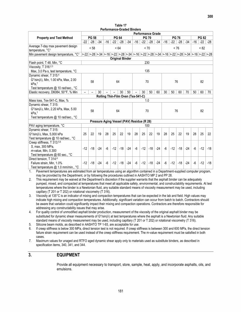
2.10. Performance-Graded Binders. Provide PG binders that are smooth and homogeneous, show no separation when tested in accordance with Tex-540-C, and meet the requirements of Table 17.
Separation testing is not required if:
a modifier is introduced separately at the mix plant either by injection in the asphalt line or mixer,
the binder is blended on site in continuously agitated tanks, or
binder acceptance is based on field samples taken from an in-line sampling port at the hot-mix plant
after the addition of modifiers.
300
181
Table 17 Performance-Graded Binders
Property and Test Method
Performance Grade
PG 58 PG 64 PG 70 PG 76 PG 82
-22 -28 -34 -16 -22 -28 -34 -16 -22 -28 -34 -16 -22 -28 -34 -16 -22 -28
Average 7-day max pavement design temperature, °C1
< 58 < 64 < 70 < 76 < 82
Min pavement design temperature, °C1 >-22 >-28 >-34 >-16 >-22 >-28 >-34 >-16 >-22 >-28 >-34 >-16 >-22 >-28 >-34 >-16 >-22 >-28
Original Binder
Flash point, T 48, Min, °C 230
Viscosity, T 316:2,3 Max, 3.0 Pas, test temperature, °C 135
Dynamic shear, T 315:4
58 64 70 76 82 G*/sin(), Min, 1.00 kPa, Max, 2.00
kPa,7 Test temperature @ 10 rad/sec., °C
Elastic recovery, D6084, 50°F, % Min – – 30 – – 30 50 – 30 50 60 30 50 60 70 50 60 70
Rolling Thin-Film Oven (Tex-541-C)
Mass loss, Tex-541-C, Max, % 1.0
Dynamic shear, T 315:
58 64 70 76 82 G*/sin(, Min, 2.20 kPa, Max, 5.00
kPa,7 Test temperature @ 10 rad/sec., °C
Pressure Aging Vessel (PAV) Residue (R 28)
PAV aging temperature, °C 100
Dynamic shear, T 315:
25 22 19 28 25 22 19 28 25 22 19 28 25 22 19 28 25 22 G*/sin(, Max, 5,000 kPa Test temperature @ 10 rad/sec., °C
Creep stiffness, T 313:5,6
-12 -18 -24 -6 -12 -18 -24 -6 -12 -18 -24 -6 -12 -18 -24 -6 -12 -18 S, max, 300 MPa,
m-value, Min, 0.300 Test temperature @ 60 sec., °C
Direct tension, T 314:6 -12 -18 -24 -6 -12 -18 -24 -6 -12 -18 -24 -6 -12 -18 -24 -6 -12 -18 Failure strain, Min, 1.0%
Test temperature @ 1.0 mm/min., °C
1. Pavement temperatures are estimated from air temperatures using an algorithm contained in a Department-supplied computer program, may be provided by the Department, or by following the procedures outlined in AASHTO MP 2 and PP 28.
2. This requirement may be waived at the Department’s discretion if the supplier warrants that the asphalt binder can be adequately pumped, mixed, and compacted at temperatures that meet all applicable safety, environmental, and constructability requirements. At test temperatures where the binder is a Newtonian fluid, any suitable standard means of viscosity measurement may be used, including capillary (T 201 or T 202) or rotational viscometry (T 316).
3. Viscosity at 135°C is an indicator of mixing and compaction temperatures that can be expected in the lab and field. High values may indicate high mixing and compaction temperatures. Additionally, significant variation can occur from batch to batch. Contractors should be aware that variation could significantly impact their mixing and compaction operations. Contractors are therefore responsible for addressing any constructability issues that may arise.
4. For quality control of unmodified asphalt binder production, measurement of the viscosity of the original asphalt binder may be
substituted for dynamic shear measurements of G*/sin() at test temperatures where the asphalt is a Newtonian fluid. Any suitable standard means of viscosity measurement may be used, including capillary (T 201 or T 202) or rotational viscometry (T 316).
5. Silicone beam molds, as described in AASHTO TP 1-93, are acceptable for use. 6. If creep stiffness is below 300 MPa, direct tension test is not required. If creep stiffness is between 300 and 600 MPa, the direct tension
failure strain requirement can be used instead of the creep stiffness requirement. The m-value requirement must be satisfied in both cases.
7. Maximum values for unaged and RTFO aged dynamic shear apply only to materials used as substitute binders, as described in specification items, 340, 341, and 344.
3. EQUIPMENT
Provide all equipment necessary to transport, store, sample, heat, apply, and incorporate asphalts, oils, and emulsions.

300
182
4. CONSTRUCTION
Typical Material Use. Use materials shown in Table 18, unless otherwise determined by the Engineer.
Table 18 Typical Material Use
Material Application Typically Used Materials
Hot-mixed, hot-laid asphalt mixtures PG binders, A-R binders Types I and II
Surface treatment AC-5, AC-10, AC-5 w/2% SBR, AC-10 w/2% SBR, AC-15P, AC-20XP, AC-10-2TR, AC-20-5TR, HFRS-2, MS-2, CRS-2, CRS-2H, HFRS-2P,CRS-2P, CHFRS-2P, A-R binders Types II and III
Surface treatment (cool weather) RS-1P, CRS-1P, RC-250, RC-800, RC-3000, MC-250, MC-800, MC-3000, MC-2400L
Precoating AC-5, AC-10, PG 64-22, SS-1, SS-1H, CSS-1, CSS-1H
Tack coat PG Binders, SS-1H, CSS-1H, EAP&T
Fog seal SS-1, SS-1H, CSS-1, CSS-1H
Hot-mixed, cold-laid asphalt mixtures AC-0.6, AC-1.5, AC-3, AES-300, AES-300P, CMS-2, CMS-2S
Patching mix MC-800, SCM I, SCM II, AES-300S
Recycling AC-0.6, AC-1.5, AC-3, AES-150P, AES-300P, recycling agent, emulsified recycling agent
Crack sealing SS-1P, polymer mod AE crack sealant, rubber asphalt crack sealers (Class A, Class B)
Microsurfacing CSS-1P
Prime MC-30, AE-P, EAP&T, PCE
Curing membrane SS-1, SS-1H, CSS-1, CSS-1H, PCE
Erosion control SS-1, SS-1H, CSS-1, CSS-1H, PCE
4.1. Storage and Application Temperatures. Use storage and application temperatures in accordance with Table 19. Store and apply materials at the lowest temperature yielding satisfactory results. Follow the manufacturer’s instructions for any agitation requirements in storage. Manufacturer’s instructions regarding recommended application and storage temperatures supersede those of Table 19.
Table 19 Storage and Application Temperatures
Type–Grade
Application Storage Maximum
(°F) Recommended Range
(°F) Maximum Allowable
(°F)
AC-0.6, AC-1.5, AC-3 200–300 350 350
AC-5, AC-10 275–350 350 350
AC-5 w/2% SBR, AC-10 w/2% SBR, AC-15P, AC-20-5TR 300–375 375 360
RC-250 125–180 200 200
RC-800 170–230 260 260
RC-3000 215–275 285 285
MC-30, AE-P 70–150 175 175
MC-250 125–210 240 240
MC-800, SCM I, SCM II 175–260 275 275
MC-3000, MC-2400L 225–275 290 290
HFRS-2, MS-2, CRS-2, CRS-2H, HFRS-2P, CRS-2P, CMS-2, CMS-2S, AES-300, AES-300S, AES-150P, AES-300P
120–160 180 180
SS-1, SS-1H, CSS-1, CSS-1H, PCE, EAP&T, SS-1P, RS-1P, CRS-1P, CSS-1P, recycling agent, emulsified recycling agent, polymer mod AE crack sealant
50–130 140 140
PG binders 275–350 350 350
Rubber asphalt crack sealers (Class A, Class B) 350–375 400 –
A-R binders Types I, II, and III 325–425 425 425
5. MEASUREMENT AND PAYMENT
The work performed, materials furnished, equipment, labor, tools, and incidentals will not be measured or paid for directly but is subsidiary or is included in payment for other pertinent Items.
302
185
Item 302
Aggregates for Surface Treatments
1. DESCRIPTION
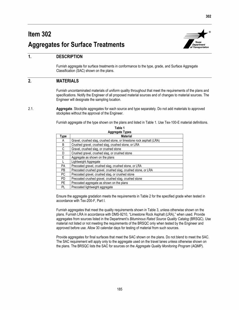
Furnish aggregate for surface treatments in conformance to the type, grade, and Surface Aggregate Classification (SAC) shown on the plans.
2. MATERIALS
Furnish uncontaminated materials of uniform quality throughout that meet the requirements of the plans and specifications. Notify the Engineer of all proposed material sources and of changes to material sources. The Engineer will designate the sampling location.
2.1. Aggregate. Stockpile aggregates for each source and type separately. Do not add materials to approved stockpiles without the approval of the Engineer.
Furnish aggregate of the type shown on the plans and listed in Table 1. Use Tex-100-E material definitions.
Table 1 Aggregate Types
Type Material
A Gravel, crushed slag, crushed stone, or limestone rock asphalt (LRA)
B Crushed gravel, crushed slag, crushed stone, or LRA
C Gravel, crushed slag, or crushed stone
D Crushed gravel, crushed slag, or crushed stone
E Aggregate as shown on the plans
L Lightweight Aggregate
PA Precoated gravel, crushed slag, crushed stone, or LRA
PB Precoated crushed gravel, crushed slag, crushed stone, or LRA
PC Precoated gravel, crushed slag, or crushed stone
PD Precoated crushed gravel, crushed slag, crushed stone
PE Precoated aggregate as shown on the plans
PL Precoated lightweight aggregate
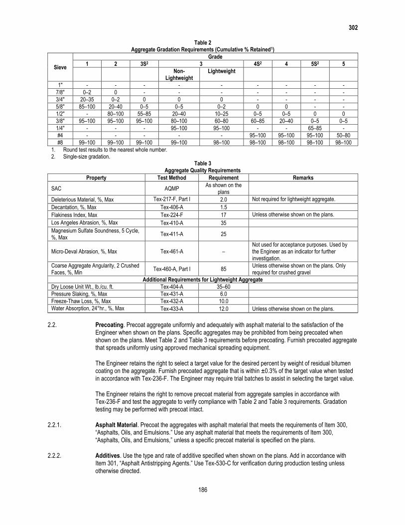
Ensure the aggregate gradation meets the requirements in Table 2 for the specified grade when tested in accordance with Tex-200-F, Part I.
Furnish aggregates that meet the quality requirements shown in Table 3, unless otherwise shown on the plans. Furnish LRA in accordance with DMS-9210, “Limestone Rock Asphalt (LRA),” when used. Provide aggregates from sources listed in the Department’s Bituminous Rated Source Quality Catalog (BRSQC). Use material not listed or not meeting the requirements of the BRSQC only when tested by the Engineer and approved before use. Allow 30 calendar days for testing of material from such sources.
Provide aggregates for final surfaces that meet the SAC shown on the plans. Do not blend to meet the SAC. The SAC requirement will apply only to the aggregate used on the travel lanes unless otherwise shown on the plans. The BRSQC lists the SAC for sources on the Aggregate Quality Monitoring Program (AQMP).
302
186
Table 2 Aggregate Gradation Requirements (Cumulative % Retained1)
Sieve
Grade
1 2 3S2 3 4S2 4 5S2 5
Non-Lightweight
Lightweight
1" - - - - - - - - -
7/8" 0–2 0 - - - - - - -
3/4" 20–35 0–2 0 0 0 - - - -
5/8" 85–100 20–40 0–5 0–5 0–2 0 0 - -
1/2" - 80–100 55–85 20–40 10–25 0–5 0–5 0 0
3/8" 95–100 95–100 95–100 80–100 60–80 60–85 20–40 0–5 0–5
1/4" - - - 95–100 95–100 - - 65–85 -
#4 - - - - - 95–100 95–100 95–100 50–80
#8 99–100 99–100 99–100 99–100 98–100 98–100 98–100 98–100 98–100
1. Round test results to the nearest whole number. 2. Single-size gradation.
Table 3 Aggregate Quality Requirements
Property Test Method Requirement Remarks
SAC AQMP As shown on the
plans
Deleterious Material, %, Max Tex-217-F, Part I 2.0 Not required for lightweight aggregate.
Decantation, %, Max Tex-406-A 1.5
Flakiness Index, Max Tex-224-F 17 Unless otherwise shown on the plans.
Los Angeles Abrasion, %, Max Tex-410-A 35
Magnesium Sulfate Soundness, 5 Cycle, %, Max
Tex-411-A 25
Micro-Deval Abrasion, %, Max Tex-461-A – Not used for acceptance purposes. Used by the Engineer as an indicator for further investigation.
Coarse Aggregate Angularity, 2 Crushed Faces, %, Min
Tex-460-A, Part I 85 Unless otherwise shown on the plans. Only required for crushed gravel
Additional Requirements for Lightweight Aggregate
Dry Loose Unit Wt., lb./cu. ft. Tex-404-A 35–60
Pressure Slaking, %, Max Tex-431-A 6.0
Freeze-Thaw Loss, %, Max Tex-432-A 10.0
Water Absorption, 24°hr., %, Max Tex-433-A 12.0 Unless otherwise shown on the plans.
2.2. Precoating. Precoat aggregate uniformly and adequately with asphalt material to the satisfaction of the Engineer when shown on the plans. Specific aggregates may be prohibited from being precoated when shown on the plans. Meet Table 2 and Table 3 requirements before precoating. Furnish precoated aggregate that spreads uniformly using approved mechanical spreading equipment.
The Engineer retains the right to select a target value for the desired percent by weight of residual bitumen coating on the aggregate. Furnish precoated aggregate that is within ±0.3% of the target value when tested in accordance with Tex-236-F. The Engineer may require trial batches to assist in selecting the target value.
The Engineer retains the right to remove precoat material from aggregate samples in accordance with Tex-236-F and test the aggregate to verify compliance with Table 2 and Table 3 requirements. Gradation testing may be performed with precoat intact.
2.2.1. Asphalt Material. Precoat the aggregates with asphalt material that meets the requirements of Item 300, “Asphalts, Oils, and Emulsions.” Use any asphalt material that meets the requirements of Item 300, “Asphalts, Oils, and Emulsions,” unless a specific precoat material is specified on the plans.
2.2.2. Additives. Use the type and rate of additive specified when shown on the plans. Add in accordance with Item 301, “Asphalt Antistripping Agents.” Use Tex-530-C for verification during production testing unless otherwise directed.

302
187
3. EQUIPMENT
Manufacture precoated aggregate in a mixing plant that produces uniformly coated aggregate.
4. CONSTRUCTION
Deliver aggregate to the locations shown on the plans. Prevent segregation, mixing of the various materials or sizes, and contamination with foreign materials when aggregates are stockpiled. The Engineer will reject contaminated stockpiles.
Provide adequate initial cooling of precoated aggregate to prevent asphalt or aggregate damage due to excessive heat buildup in stockpiles. Limit stockpile height to 3 ft. immediately after production when asphalt cement is the precoating material. Consolidate stockpiles after adequate cooling, as approved. The Engineer will reject stockpiles showing evidence of damage due to excessive heat buildup.
5. MEASUREMENT AND PAYMENT
The work performed, materials furnished, equipment, tools, and incidentals will not be measured or paid for directly but is subsidiary to or included under “Payment” in other pertinent Items.

314
191
Item 314
Emulsified Asphalt Treatment
1. DESCRIPTION
Apply an emulsified asphalt and water mixture as a base or subgrade treatment; for erosion control, including dust prevention; or as a prime coat.
2. MATERIALS
Furnish materials in accordance with the following.
Item 204, “Sprinkling”
Item 300, “Asphalts, Oils, and Emulsions”
Use emulsified asphalt of the type and grade shown on the plans. Use a quantity of emulsified asphalt in the mixture, expressed as a percent of total volume, in accordance with the percentage shown on the plans or as directed.
3. EQUIPMENT
Provide a self-propelled sprinkler in accordance with Article 204.3., “Equipment.” Provide current calibration documentation for the tank used for distribution.
4. CONSTRUCTION
Agitate the water and emulsified asphalt to produce a uniform blend. Evenly distribute at the rate selected by the Engineer to locations shown on the plans or as directed.
4.1. Base or Subgrade Treatment. Treat the base or subgrade to the depth and width shown on the plans or as directed.
Regulate the percentage of emulsified asphalt in the mixture and distribute successive applications to achieve the specified rate. Maintain the proper moisture content of the treated material. Mix the treated material, then shape and compact as required by the specification for the course. Finish the course to the line, grade, and typical section shown on the plans. Maintain the surface with light applications of the emulsified asphalt mixture while curing the course, as directed.
4.2. Erosion Control. Apply the mixture as shown on the plans or as directed.
4.3. Prime Coat. Regulate the percentage of emulsified asphalt in the mixture and distribute successive applications to achieve the specified rate.
5. MEASUREMENT
The treatment will be measured by the gallon of emulsified asphalt used in the emulsified asphalt and water mixture.

314
192
6. PAYMENT
The work performed and materials furnished in accordance with this Item and measured as provided under “Measurement” will be paid for at the unit price bid for “Emulsified Asphalt (Base or Subgrade Treatment),” “Emulsified Asphalt (Erosion Control),” or “Emulsified Asphalt (Prime Coat),” of the type and grade specified. This price is full compensation for materials, including emulsified asphalt and water, and for equipment, labor, tools, and incidentals.

340
213
Item 340
Dense-Graded Hot-Mix Asphalt (Small Quantity)
1. DESCRIPTION
Construct a hot-mix asphalt (HMA) pavement layer composed of a compacted, dense-graded mixture of aggregate and asphalt binder mixed hot in a mixing plant. This specification is intended for small quantity (SQ) HMA projects, typically under 5,000 tons total production.
2. MATERIALS
Furnish uncontaminated materials of uniform quality that meet the requirements of the plans and specifications.
Notify the Engineer of all material sources and before changing any material source or formulation. The Engineer will verify that the specification requirements are met when the Contractor makes a source or formulation change, and may require a new laboratory mixture design, trial batch, or both. The Engineer may sample and test project materials at any time during the project to verify specification compliance in accordance with Item 6, “Control of Materials.”
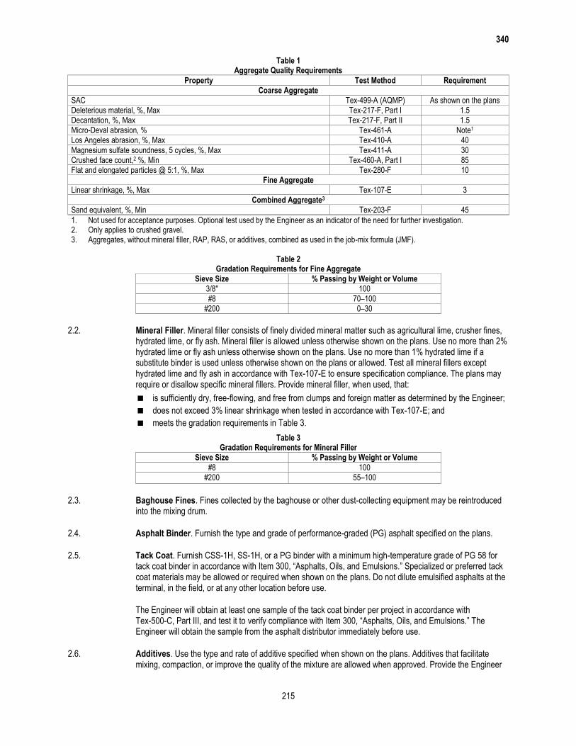
2.1. Aggregate. Furnish aggregates from sources that conform to the requirements shown in Table 1 and as specified in this Section. Aggregate requirements in this Section, including those shown in Table 1, may be modified or eliminated when shown on the plans. Additional aggregate requirements may be specified when shown on the plans. Provide aggregate stockpiles that meet the definitions in this Section for coarse, intermediate, or fine aggregate. Aggregate from reclaimed asphalt pavement (RAP) is not required to meet Table 1 requirements unless otherwise shown on the plans. Supply aggregates that meet the definitions in Tex-100-E for crushed gravel or crushed stone. The Engineer will designate the plant or the quarry as the sampling location. Provide samples from materials produced for the project. The Engineer will establish the Surface Aggregate Classification (SAC) and perform Los Angeles abrasion, magnesium sulfate soundness, and Micro-Deval tests. Perform all other aggregate quality tests listed in Table 1. Document all test results on the mixture design report. The Engineer may perform tests on independent or split samples to verify Contractor test results. Stockpile aggregates for each source and type separately. Determine aggregate gradations for mixture design and production testing based on the washed sieve analysis given in Tex-200-F, Part II.
2.1.1. Coarse Aggregate. Coarse aggregate stockpiles must have no more than 20% material passing the No. 8 sieve. Aggregates from sources listed in the Department’s Bituminous Rated Source Quality Catalog (BRSQC) are preapproved for use. Use only the rated values for hot-mix listed in the BRSQC. Rated values for surface treatment (ST) do not apply to coarse aggregate sources used in hot-mix asphalt.
For sources not listed on the Department’s BRSQC:
build an individual stockpile for each material;
request the Department test the stockpile for specification compliance; and
once approved, do not add material to the stockpile unless otherwise approved.
Provide aggregate from non-listed sources only when tested by the Engineer and approved before use. Allow 30 calendar days for the Engineer to sample, test, and report results for non-listed sources.
Provide coarse aggregate with at least the minimum SAC shown on the plans. SAC requirements only apply to aggregates used on the surface of travel lanes. SAC requirements apply to aggregates used on surfaces other than travel lanes when shown on the plans. The SAC for sources on the Department’s Aggregate Quality Monitoring Program (AQMP) (Tex-499-A) is listed in the BRSQC.

340
214
2.1.1.1. Blending Class A and Class B Aggregates. Class B aggregate meeting all other requirements in Table 1 may be blended with a Class A aggregate to meet requirements for Class A materials. Ensure that at least 50% by weight, or volume if required, of the material retained on the No. 4 sieve comes from the Class A aggregate source when blending Class A and B aggregates to meet a Class A requirement. Blend by volume if the bulk specific gravities of the Class A and B aggregates differ by more than 0.300. Coarse aggregate from RAP and Recycled Asphalt Shingles (RAS) will be considered as Class B aggregate for blending purposes.
The Engineer may perform tests at any time during production, when the Contractor blends Class A and B aggregates to meet a Class A requirement, to ensure that at least 50% by weight, or volume if required, of the material retained on the No. 4 sieve comes from the Class A aggregate source. The Engineer will use the Department’s mix design Excel template, when electing to verify conformance, to calculate the percent of Class A aggregate retained on the No. 4 sieve by inputting the bin percentages shown from readouts in the control room at the time of production and stockpile gradations measured at the time of production. The Engineer may determine the gradations based on either washed or dry sieve analysis from samples obtained from individual aggregate cold feed bins or aggregate stockpiles. The Engineer may perform spot checks using the gradations supplied by the Contractor on the mixture design report as an input for the Excel template; however, a failing spot check will require confirmation with a stockpile gradation determined by the Engineer.
2.1.2. Intermediate Aggregate. Aggregates not meeting the definition of coarse or fine aggregate will be defined as intermediate aggregate. Supply intermediate aggregates, when used, that are free from organic impurities.
The Engineer may test the intermediate aggregate in accordance with Tex-408-A to verify the material is free from organic impurities. Supply intermediate aggregate from coarse aggregate sources, when used, that meet the requirements shown in Table 1 unless otherwise approved.
Test the stockpile if 10% or more of the stockpile is retained on the No. 4 sieve, and verify that it meets the requirements in Table 1 for crushed face count (Tex-460-A) and flat and elongated particles (Tex-280-F).
2.1.3. Fine Aggregate. Fine aggregates consist of manufactured sands, screenings, and field sands. Fine aggregate stockpiles must meet the gradation requirements in Table 2. Supply fine aggregates that are free from organic impurities. The Engineer may test the fine aggregate in accordance with Tex-408-A to verify the material is free from organic impurities. No more than 15% of the total aggregate may be field sand or other uncrushed fine aggregate. Use fine aggregate, with the exception of field sand, from coarse aggregate sources that meet the requirements shown in Table 1 unless otherwise approved.
Test the stockpile if 10% or more of the stockpile is retained on the No. 4 sieve, and verify that it meets the requirements in Table 1 for crushed face count (Tex-460-A) and flat and elongated particles (Tex-280-F).
340
215
Table 1 Aggregate Quality Requirements
Property Test Method Requirement
Coarse Aggregate
SAC Tex-499-A (AQMP) As shown on the plans
Deleterious material, %, Max Tex-217-F, Part I 1.5
Decantation, %, Max Tex-217-F, Part II 1.5
Micro-Deval abrasion, % Tex-461-A Note1
Los Angeles abrasion, %, Max Tex-410-A 40
Magnesium sulfate soundness, 5 cycles, %, Max Tex-411-A 30
Crushed face count,2 %, Min Tex-460-A, Part I 85
Flat and elongated particles @ 5:1, %, Max Tex-280-F 10
Fine Aggregate
Linear shrinkage, %, Max Tex-107-E 3
Combined Aggregate3
Sand equivalent, %, Min Tex-203-F 45
1. Not used for acceptance purposes. Optional test used by the Engineer as an indicator of the need for further investigation. 2. Only applies to crushed gravel. 3. Aggregates, without mineral filler, RAP, RAS, or additives, combined as used in the job-mix formula (JMF).
Table 2
Gradation Requirements for Fine Aggregate
Sieve Size % Passing by Weight or Volume
3/8″ 100
#8 70–100
#200 0–30
2.2. Mineral Filler. Mineral filler consists of finely divided mineral matter such as agricultural lime, crusher fines, hydrated lime, or fly ash. Mineral filler is allowed unless otherwise shown on the plans. Use no more than 2% hydrated lime or fly ash unless otherwise shown on the plans. Use no more than 1% hydrated lime if a substitute binder is used unless otherwise shown on the plans or allowed. Test all mineral fillers except hydrated lime and fly ash in accordance with Tex-107-E to ensure specification compliance. The plans may require or disallow specific mineral fillers. Provide mineral filler, when used, that:
is sufficiently dry, free-flowing, and free from clumps and foreign matter as determined by the Engineer;
does not exceed 3% linear shrinkage when tested in accordance with Tex-107-E; and
meets the gradation requirements in Table 3.
Table 3 Gradation Requirements for Mineral Filler
Sieve Size % Passing by Weight or Volume
#8 100
#200 55–100
2.3. Baghouse Fines. Fines collected by the baghouse or other dust-collecting equipment may be reintroduced into the mixing drum.
2.4. Asphalt Binder. Furnish the type and grade of performance-graded (PG) asphalt specified on the plans.
2.5. Tack Coat. Furnish CSS-1H, SS-1H, or a PG binder with a minimum high-temperature grade of PG 58 for tack coat binder in accordance with Item 300, “Asphalts, Oils, and Emulsions.” Specialized or preferred tack coat materials may be allowed or required when shown on the plans. Do not dilute emulsified asphalts at the terminal, in the field, or at any other location before use.
The Engineer will obtain at least one sample of the tack coat binder per project in accordance with Tex-500-C, Part III, and test it to verify compliance with Item 300, “Asphalts, Oils, and Emulsions.” The Engineer will obtain the sample from the asphalt distributor immediately before use.
2.6. Additives. Use the type and rate of additive specified when shown on the plans. Additives that facilitate mixing, compaction, or improve the quality of the mixture are allowed when approved. Provide the Engineer
340
216
with documentation, such as the bill of lading, showing the quantity of additives used in the project unless otherwise directed.
2.6.1. Lime and Liquid Antistripping Agent. When lime or a liquid antistripping agent is used, add in accordance with Item 301, “Asphalt Antistripping Agents.” Do not add lime directly into the mixing drum of any plant where lime is removed through the exhaust stream unless the plant has a baghouse or dust collection system that reintroduces the lime into the drum.
2.6.2. Warm Mix Asphalt (WMA). Warm Mix Asphalt (WMA) is defined as HMA that is produced within a target temperature discharge range of 215°F and 275°F using approved WMA additives or processes from the Department’s MPL.
WMA is allowed for use on all projects and is required when shown on the plans. When WMA is required, the maximum placement or target discharge temperature for WMA will be set at a value below 275°F.
Department-approved WMA additives or processes may be used to facilitate mixing and compaction of HMA produced at target discharge temperatures above 275°F; however, such mixtures will not be defined as WMA.
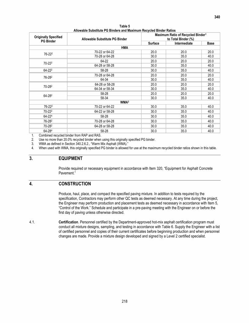
2.7. Recycled Materials. Use of RAP and RAS is permitted unless otherwise shown on the plans. Do not exceed the maximum allowable percentages of RAP and RAS shown in Table 4. The allowable percentages shown in Table 4 may be decreased or increased when shown on the plans. Determine asphalt binder content and gradation of the RAP and RAS stockpiles for mixture design purposes in accordance with Tex-236-F. The Engineer may verify the asphalt binder content of the stockpiles at any time during production. Perform other tests on RAP and RAS when shown on the plans. Asphalt binder from RAP and RAS is designated as recycled asphalt binder. Calculate and ensure that the ratio of the recycled asphalt binder to total binder does not exceed the percentages shown in Table 5 during mixture design and HMA production when RAP or RAS is used. Use a separate cold feed bin for each stockpile of RAP and RAS during HMA production.
Surface, intermediate, and base mixes referenced in Tables 4 and 5 are defined as follows:
Surface. The final HMA lift placed at or near the top of the pavement structure;
Intermediate. Mixtures placed below an HMA surface mix and less than or equal to 8.0 in. from the
riding surface; and
Base. Mixtures placed greater than 8.0 in. from the riding surface.
2.7.1. RAP. RAP is salvaged, milled, pulverized, broken, or crushed asphalt pavement. Crush or break RAP so that 100% of the particles pass the 2 in. sieve. Fractionated RAP is defined as 2 or more RAP stockpiles, divided into coarse and fine fractions.
Use of Contractor-owned RAP, including HMA plant waste, is permitted unless otherwise shown on the plans. Department-owned RAP stockpiles are available for the Contractor’s use when the stockpile locations are shown on the plans. If Department-owned RAP is available for the Contractor’s use, the Contractor may use Contractor-owned fractionated RAP and replace it with an equal quantity of Department-owned RAP. This allowance does not apply to a Contractor using unfractionated RAP. Department-owned RAP generated through required work on the Contract is available for the Contractor’s use when shown on the plans. Perform any necessary tests to ensure Contractor- or Department-owned RAP is appropriate for use. The Department will not perform any tests or assume any liability for the quality of the Department-owned RAP unless otherwise shown on the plans. The Contractor will retain ownership of RAP generated on the project when shown on the plans.
The coarse RAP stockpile will contain only material retained by processing over a 3/8-in. or 1/2-in. screen unless otherwise approved. The fine RAP stockpile will contain only material passing the 3/8-in. or 1/2-in. screen unless otherwise approved. The Engineer may allow the Contractor to use an alternate to the 3/8-in. or 1/2-in. screen to fractionate the RAP. The maximum percentages of fractionated RAP may be comprised of coarse or fine fractionated RAP or the combination of both coarse and fine fractionated RAP.

340
217
Do not use Department- or Contractor-owned RAP contaminated with dirt or other objectionable materials. Do not use Department- or Contractor-owned RAP if the decantation value exceeds 5% and the plasticity index is greater than 8. Test the stockpiled RAP for decantation in accordance with Tex-406-A, Part I. Determine the plasticity index in accordance with Tex-106-E if the decantation value exceeds 5%. The decantation and plasticity index requirements do not apply to RAP samples with asphalt removed by extraction or ignition.
Do not intermingle Contractor-owned RAP stockpiles with Department-owned RAP stockpiles. Remove unused Contractor-owned RAP material from the project site upon completion of the project. Return unused Department-owned RAP to the designated stockpile location.
Table 4 Maximum Allowable Amounts of RAP1
Maximum Allowable Fractionated RAP2 (%)
Maximum Allowable Unfractionated RAP3 (%)
Surface Intermediate Base Surface Intermediate Base
20.0 30.0 40.0 10.0 10.0 10.0
1. Must also meet the recycled binder to total binder ratio shown in Table 5. 2. Up to 5% RAS may be used separately or as a replacement for fractionated RAP. 3. Unfractionated RAP may not be combined with fractionated RAP or RAS.
2.7.2. RAS. Use of post-manufactured RAS or post-consumer RAS (tear-offs) is permitted unless otherwise shown on the plans. Up to 5% RAS may be used separately or as a replacement for fractionated RAP in accordance with Table 4 and Table 5. RAS is defined as processed asphalt shingle material from manufacturing of asphalt roofing shingles or from re-roofing residential structures. Post-manufactured RAS is processed manufacturer’s shingle scrap by-product. Post-consumer RAS is processed shingle scrap removed from residential structures. Comply with all regulatory requirements stipulated for RAS by the TCEQ. RAS may be used separately or in conjunction with RAP.
Process the RAS by ambient grinding or granulating such that 100% of the particles pass the 3/8 in. sieve when tested in accordance with Tex-200-F, Part I. Perform a sieve analysis on processed RAS material before extraction (or ignition) of the asphalt binder.
Add sand meeting the requirements of Table 1 and Table 2 or fine RAP to RAS stockpiles if needed to keep the processed material workable. Any stockpile that contains RAS will be considered a RAS stockpile and be limited to no more than 5.0% of the HMA mixture in accordance with Table 4.
Certify compliance of the RAS with DMS-11000, “Evaluating and Using Nonhazardous Recyclable Materials Guidelines.” Treat RAS as an established nonhazardous recyclable material if it has not come into contact with any hazardous materials. Use RAS from shingle sources on the Department’s MPL. Remove substantially all materials before use that are not part of the shingle, such as wood, paper, metal, plastic, and felt paper. Determine the deleterious content of RAS material for mixture design purposes in accordance with Tex-217-F, Part III. Do not use RAS if deleterious materials are more than 0.5% of the stockpiled RAS unless otherwise approved. Submit a sample for approval before submitting the mixture design. The Department will perform the testing for deleterious material of RAS to determine specification compliance.
2.8. Substitute Binders. Unless otherwise shown on the plans, the Contractor may use a substitute PG binder listed in Table 5 instead of the PG binder originally specified, if the substitute PG binder and mixture made with the substitute PG binder meet the following:
the substitute binder meets the specification requirements for the substitute binder grade in accordance
with Section 300.2.10., “Performance-Graded Binders”; and
the mixture has less than 10.0 mm of rutting on the Hamburg Wheel test (Tex-242-F) after the number
of passes required for the originally specified binder. Use of substitute PG binders may only be allowed
at the discretion of the Engineer if the Hamburg Wheel test results are between 10.0 mm and 12.5 mm.
340
218
Table 5 Allowable Substitute PG Binders and Maximum Recycled Binder Ratios
Originally Specified PG Binder
Allowable Substitute PG Binder Maximum Ratio of Recycled Binder1
to Total Binder (%)
Surface Intermediate Base
HMA
76-222 70-22 or 64-22 20.0 20.0 20.0
70-28 or 64-28 30.0 35.0 40.0
70-222 64-22 20.0 20.0 20.0
64-28 or 58-28 30.0 35.0 40.0
64-222 58-28 30.0 35.0 40.0
76-282 70-28 or 64-28 20.0 20.0 20.0
64-34 30.0 35.0 40.0
70-282 64-28 or 58-28 20.0 20.0 20.0
64-34 or 58-34 30.0 35.0 40.0
64-282 58-28 20.0 20.0 20.0
58-34 30.0 35.0 40.0
WMA3
76-222 70-22 or 64-22 30.0 35.0 40.0
70-222 64-22 or 58-28 30.0 35.0 40.0
64-224 58-28 30.0 35.0 40.0
76-282 70-28 or 64-28 30.0 35.0 40.0
70-282 64-28 or 58-28 30.0 35.0 40.0
64-284 58-28 30.0 35.0 40.0
1. Combined recycled binder from RAP and RAS. 2. Use no more than 20.0% recycled binder when using this originally specified PG binder. 3. WMA as defined in Section 340.2.6.2., “Warm Mix Asphalt (WMA).” 4. When used with WMA, this originally specified PG binder is allowed for use at the maximum recycled binder ratios shown in this table.
3. EQUIPMENT
Provide required or necessary equipment in accordance with Item 320, “Equipment for Asphalt Concrete Pavement.”
4. CONSTRUCTION
Produce, haul, place, and compact the specified paving mixture. In addition to tests required by the specification, Contractors may perform other QC tests as deemed necessary. At any time during the project, the Engineer may perform production and placement tests as deemed necessary in accordance with Item 5, “Control of the Work.” Schedule and participate in a pre-paving meeting with the Engineer on or before the first day of paving unless otherwise directed.
4.1. Certification. Personnel certified by the Department-approved hot-mix asphalt certification program must conduct all mixture designs, sampling, and testing in accordance with Table 6. Supply the Engineer with a list of certified personnel and copies of their current certificates before beginning production and when personnel changes are made. Provide a mixture design developed and signed by a Level 2 certified specialist.

340
219
Table 6 Test Methods, Test Responsibility, and Minimum Certification Levels
Test Description Test Method Contractor Engineer Level1
1. Aggregate and Recycled Material Testing
Sampling Tex-221-F 1A
Dry sieve Tex-200-F, Part I 1A
Washed sieve Tex-200-F, Part II 1A
Deleterious material Tex-217-F, Parts I & III 1A
Decantation Tex-217-F, Part II 1A
Los Angeles abrasion Tex-410-A TxDOT
Magnesium sulfate soundness Tex-411-A TxDOT
Micro-Deval abrasion Tex-461-A 2
Crushed face count Tex-460-A 2
Flat and elongated particles Tex-280-F 2
Linear shrinkage Tex-107-E 2
Sand equivalent Tex-203-F 2
Organic impurities Tex-408-A 2
2. Asphalt Binder & Tack Coat Sampling
Asphalt binder sampling Tex-500-C, Part II 1A/1B
Tack coat sampling Tex-500-C, Part III 1A/1B
3. Mix Design & Verification
Design and JMF changes Tex-204-F 2
Mixing Tex-205-F 2
Molding (TGC) Tex-206-F 1A
Molding (SGC) Tex-241-F 1A
Laboratory-molded density Tex-207-F 1A
VMA2 (calculation only) Tex-204-F 2
Rice gravity Tex-227-F 1A
Ignition oven correction factors3 Tex-236-F 2
Indirect tensile strength Tex-226-F 2
Hamburg Wheel test Tex-242-F 2
Boil test Tex-530-C 1A
4. Production Testing
Mixture sampling Tex-222-F 1A
Molding (TGC) Tex-206-F 1A
Molding (SGC) Tex-241-F 1A
Laboratory-molded density Tex-207-F 1A
VMA2 (calculation only) Tex-204-F 1A
Rice gravity Tex-227-F 1A
Gradation & asphalt binder content3 Tex-236-F 1A
Moisture content Tex-212-F 1A
Hamburg Wheel test Tex-242-F 2
Boil test Tex-530-C 1A
5. Placement Testing
Trimming roadway cores Tex-207-F 1A/1B
In-place air voids Tex-207-F 1A/1B
Establish rolling pattern Tex-207-F 1B
Ride quality measurement Tex-1001-S Note4
1. Level 1A, 1B, and 2 are certification levels provided by the Hot Mix Asphalt Center certification program. 2. Voids in mineral aggregates. 3. Refer to Section 340.4.8.3., “Production Testing,” for exceptions to using an ignition oven. 4. Profiler and operator are required to be certified at the Texas A&M Transportation Institute facility when Surface Test Type B is
specified.
4.2. Reporting, Testing, and Responsibilities. Use Department-provided Excel templates to record and calculate all test data pertaining to the mixture design. The Engineer will use Department Excel templates for any production and placement testing. Obtain the latest version of the Excel templates at http://www.txdot.gov/inside-txdot/forms-publications/consultants-contractors/forms/site-manager.html or from the Engineer.
340
220
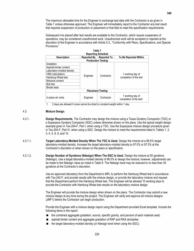
The maximum allowable time for the Engineer to exchange test data with the Contractor is as given in Table 7 unless otherwise approved. The Engineer will immediately report to the Contractor any test result that requires suspension of production or placement or that fails to meet the specification requirements.
Subsequent mix placed after test results are available to the Contractor, which require suspension of operations, may be considered unauthorized work. Unauthorized work will be accepted or rejected at the discretion of the Engineer in accordance with Article 5.3., “Conformity with Plans, Specifications, and Special Provisions.”
Table 7 Reporting Schedule
Description Reported By Reported To To Be Reported Within
Production Testing
Gradation
Engineer Contractor 1 working day of
completion of the test
Asphalt binder content
Laboratory-molded density
VMA (calculation)
Hamburg Wheel test
Moisture content
Boil test
Binder tests
Placement Testing
In-place air voids Engineer Contractor 1 working day of
completion of the test1
1. 2 days are allowed if cores cannot be dried to constant weight within 1 day.
4.3. Mixture Design.
4.3.1. Design Requirements. The Contractor may design the mixture using a Texas Gyratory Compactor (TGC) or a Superpave Gyratory Compactor (SGC) unless otherwise shown on the plans. Use the typical weight design example given in Tex-204-F, Part I, when using a TGC. Use the Superpave mixture design procedure given in Tex-204-F, Part IV, when using a SGC. Design the mixture to meet the requirements listed in Tables 1, 2, 3, 4, 5, 8, 9, and 10.
4.3.1.1. Target Laboratory-Molded Density When The TGC Is Used. Design the mixture at a 96.5% target laboratory-molded density. Increase the target laboratory-molded density to 97.0% or 97.5% at the Contractor’s discretion or when shown on the plans or specification.
4.3.1.2. Design Number of Gyrations (Ndesign) When The SGC Is Used. Design the mixture at 50 gyrations (Ndesign). Use a target laboratory-molded density of 96.0% to design the mixture; however, adjustments can be made to the Ndesign value as noted in Table 9. The Ndesign level may be reduced to no less than 35 gyrations at the Contractor’s discretion.
Use an approved laboratory from the Department’s MPL to perform the Hamburg Wheel test in accordance with Tex-242-F, and provide results with the mixture design, or provide the laboratory mixture and request that the Department perform the Hamburg Wheel test. The Engineer will be allowed 10 working days to provide the Contractor with Hamburg Wheel test results on the laboratory mixture design.
The Engineer will provide the mixture design when shown on the plans. The Contractor may submit a new mixture design at any time during the project. The Engineer will verify and approve all mixture designs (JMF1) before the Contractor can begin production.
Provide the Engineer with a mixture design report using the Department-provided Excel template. Include the following items in the report:
the combined aggregate gradation, source, specific gravity, and percent of each material used;
asphalt binder content and aggregate gradation of RAP and RAS stockpiles;
the target laboratory-molded density (or Ndesign level when using the SGC);
340
221
results of all applicable tests;
the mixing and molding temperatures;
the signature of the Level 2 person or persons that performed the design;
the date the mixture design was performed; and
a unique identification number for the mixture design.
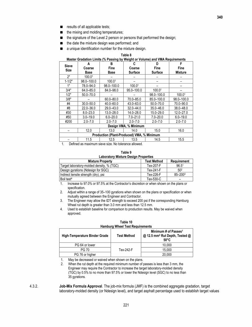
Table 8 Master Gradation Limits (% Passing by Weight or Volume) and VMA Requirements
Sieve Size
A Coarse Base
B Fine Base
C Coarse Surface
D Fine
Surface
F Fine
Mixture
2″ 100.01 – – – –
1-1/2″ 98.0–100.0 100.01 – – –
1″ 78.0–94.0 98.0–100.0 100.01 – –
3/4″ 64.0–85.0 84.0–98.0 95.0–100.0 100.01 –
1/2″ 50.0–70.0 – – 98.0–100.0 100.01
3/8″ – 60.0–80.0 70.0–85.0 85.0–100.0 98.0–100.0
#4 30.0–50.0 40.0–60.0 43.0–63.0 50.0–70.0 70.0–90.0
#8 22.0–36.0 29.0–43.0 32.0–44.0 35.0–46.0 38.0–48.0
#30 8.0–23.0 13.0–28.0 14.0–28.0 15.0–29.0 12.0–27.0
#50 3.0–19.0 6.0–20.0 7.0–21.0 7.0–20.0 6.0–19.0
#200 2.0–7.0 2.0–7.0 2.0–7.0 2.0–7.0 2.0–7.0
Design VMA, % Minimum
– 12.0 13.0 14.0 15.0 16.0
Production (Plant-Produced) VMA, % Minimum
– 11.5 12.5 13.5 14.5 15.5
1. Defined as maximum sieve size. No tolerance allowed.
Table 9 Laboratory Mixture Design Properties
Mixture Property Test Method Requirement
Target laboratory-molded density, % (TGC) Tex-207-F 96.51
Design gyrations (Ndesign for SGC) Tex-241-F 502
Indirect tensile strength (dry), psi Tex-226-F 85–2003
Boil test4 Tex-530-C –
1. Increase to 97.0% or 97.5% at the Contractor’s discretion or when shown on the plans or specification.
2. Adjust within a range of 35–100 gyrations when shown on the plans or specification or when mutually agreed between the Engineer and Contractor.
3. The Engineer may allow the IDT strength to exceed 200 psi if the corresponding Hamburg Wheel rut depth is greater than 3.0 mm and less than 12.5 mm.
4. Used to establish baseline for comparison to production results. May be waived when approved.
Table 10
Hamburg Wheel Test Requirements
High-Temperature Binder Grade Test Method Minimum # of Passes1
@ 12.5 mm2 Rut Depth, Tested @ 50°C
PG 64 or lower
Tex-242-F
10,000
PG 70 15,000
PG 76 or higher 20,000
1. May be decreased or waived when shown on the plans. 2. When the rut depth at the required minimum number of passes is less than 3 mm, the
Engineer may require the Contractor to increase the target laboratory-molded density (TGC) by 0.5% to no more than 97.5% or lower the Ndesign level (SGC) to no less than 35 gyrations.
4.3.2. Job-Mix Formula Approval. The job-mix formula (JMF) is the combined aggregate gradation, target laboratory-molded density (or Ndesign level), and target asphalt percentage used to establish target values

340
222
for hot-mix production. JMF1 is the original laboratory mixture design used to produce the trial batch. When WMA is used, JMF1 may be designed and submitted to the Engineer without including the WMA additive. When WMA is used, document the additive or process used and recommended rate on the JMF1 submittal. Furnish a mix design report (JMF1) with representative samples of all component materials and request approval to produce the trial batch. Provide approximately 10,000 g of the design mixture and request that the Department perform the Hamburg Wheel test if opting to have the Department perform the test. The Engineer will verify JMF1 based on plant-produced mixture from the trial batch unless otherwise determined. The Engineer may accept an existing mixture design previously used on a Department project and may waive the trial batch to verify JMF1. Provide split samples of the mixtures and blank samples used to determine the ignition oven correction factors. The Engineer will determine the aggregate and asphalt correction factors from the ignition oven used for production testing in accordance with Tex-236-F.
The Engineer will use a TGC calibrated in accordance with Tex-914-K in molding production samples. Provide an SGC at the Engineer’s field laboratory for use in molding production samples if the SGC is used to design the mix.
The Engineer may perform Tex-530-C and retain the tested sample for comparison purposes during production. The Engineer may waive the requirement for the boil test.
4.3.3. JMF Adjustments. If JMF adjustments are necessary to achieve the specified requirements, the adjusted JMF must:
be provided to the Engineer in writing before the start of a new lot;
be numbered in sequence to the previous JMF;
meet the mixture requirements in Table 4 and Table 5;
meet the master gradation limits shown in Table 8; and
be within the operational tolerances of the current JMF listed in Table 11.
The Engineer may adjust the asphalt binder content to maintain desirable laboratory density near the optimum value while achieving other mix requirements.
Table 11 Operational Tolerances
Description Test Method Allowable Difference Between Trial Batch and JMF1 Target
Allowable Difference from Current JMF Target
Individual % retained for #8 sieve and larger Tex-200-F
or Tex-236-F
Must be within master grading limits
in Table 8
±5.01,2
Individual % retained for sieves smaller than #8 and larger than #200
±3.01,2
% passing the #200 sieve ±2.01,2
Asphalt binder content, % Tex-236-F ±0.5 ±0.32
Laboratory-molded density, % Tex-207-F ±1.0 ±1.0
VMA, %, min Tex-204-F Note3 Note3
1. When within these tolerances, mixture production gradations may fall outside the master grading limits; however, the % passing the #200 will be considered out of tolerance when outside the master grading limits.
2. Only applies to mixture produced for Lot 1 and higher. 3. Mixture is required to meet Table 8 requirements.
4.4. Production Operations. Perform a new trial batch when the plant or plant location is changed. Take corrective action and receive approval to proceed after any production suspension for noncompliance to the specification. Submit a new mix design and perform a new trial batch when the asphalt binder content of:
any RAP stockpile used in the mix is more than 0.5% higher than the value shown on the mixture design
report; or
RAS stockpile used in the mix is more than 2.0% higher than the value shown on the mixture design
report.
4.4.1. Storage and Heating of Materials. Do not heat the asphalt binder above the temperatures specified in Item 300, “Asphalts, Oils, and Emulsions,” or outside the manufacturer’s recommended values. Provide the Engineer with daily records of asphalt binder and hot-mix asphalt discharge temperatures (in legible and
340
223
discernible increments) in accordance with Item 320, “Equipment for Asphalt Concrete Pavement,” unless otherwise directed. Do not store mixture for a period long enough to affect the quality of the mixture, nor in any case longer than 12 hr. unless otherwise approved.
4.4.2. Mixing and Discharge of Materials. Notify the Engineer of the target discharge temperature and produce the mixture within 25°F of the target. Monitor the temperature of the material in the truck before shipping to ensure that it does not exceed 350°F (or 275°F for WMA) and is not lower than 215°F. The Department will not pay for or allow placement of any mixture produced above 350°F.
Produce WMA within the target discharge temperature range of 215°F and 275°F when WMA is required. Take corrective action any time the discharge temperature of the WMA exceeds the target discharge range. The Engineer may suspend production operations if the Contractor’s corrective action is not successful at controlling the production temperature within the target discharge range. Note that when WMA is produced, it may be necessary to adjust burners to ensure complete combustion such that no burner fuel residue remains in the mixture.
Control the mixing time and temperature so that substantially all moisture is removed from the mixture before discharging from the plant. The Engineer may determine the moisture content by oven-drying in accordance with Tex-212-F, Part II, and verify that the mixture contains no more than 0.2% of moisture by weight. The Engineer will obtain the sample immediately after discharging the mixture into the truck, and will perform the test promptly.
4.5. Hauling Operations. Clean all truck beds before use to ensure that mixture is not contaminated. Use a release agent shown on the Department’s MPL to coat the inside bed of the truck when necessary.
Use equipment for hauling as defined in Section 340.4.6.3.2., “Hauling Equipment.” Use other hauling equipment only when allowed.
4.6. Placement Operations. Collect haul tickets from each load of mixture delivered to the project and provide the Department’s copy to the Engineer approximately every hour, or as directed. Use a hand-held thermal camera or infrared thermometer to measure and record the internal temperature of the mixture as discharged from the truck or Material Transfer Device (MTD) before or as the mix enters the paver and an approximate station number or GPS coordinates on each ticket unless otherwise directed. Calculate the daily yield and cumulative yield for the specified lift and provide to the Engineer at the end of paving operations for each day unless otherwise directed. The Engineer may suspend production if the Contractor fails to produce and provide haul tickets and yield calculations by the end of paving operations for each day.
Prepare the surface by removing raised pavement markers and objectionable material such as moisture, dirt, sand, leaves, and other loose impediments from the surface before placing mixture. Remove vegetation from pavement edges. Place the mixture to meet the typical section requirements and produce a smooth, finished surface with a uniform appearance and texture. Offset longitudinal joints of successive courses of hot-mix by at least 6 in. Place mixture so that longitudinal joints on the surface course coincide with lane lines, or as directed. Ensure that all finished surfaces will drain properly.
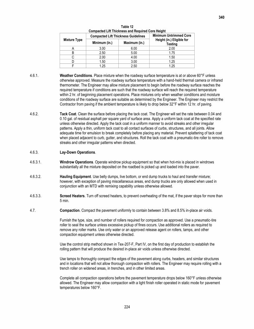
Place the mixture at the rate or thickness shown on the plans. The Engineer will use the guidelines in Table 12 to determine the compacted lift thickness of each layer when multiple lifts are required. The thickness determined is based on the rate of 110 lb./sq. yd. for each inch of pavement unless otherwise shown on the plans.
340
224
Table 12 Compacted Lift Thickness and Required Core Height
Mixture Type Compacted Lift Thickness Guidelines Minimum Untrimmed Core
Height (in.) Eligible for Testing Minimum (in.) Maximum (in.)
A 3.00 6.00 2.00
B 2.50 5.00 1.75
C 2.00 4.00 1.50
D 1.50 3.00 1.25
F 1.25 2.50 1.25
4.6.1. Weather Conditions. Place mixture when the roadway surface temperature is at or above 60°F unless otherwise approved. Measure the roadway surface temperature with a hand-held thermal camera or infrared thermometer. The Engineer may allow mixture placement to begin before the roadway surface reaches the required temperature if conditions are such that the roadway surface will reach the required temperature within 2 hr. of beginning placement operations. Place mixtures only when weather conditions and moisture conditions of the roadway surface are suitable as determined by the Engineer. The Engineer may restrict the Contractor from paving if the ambient temperature is likely to drop below 32°F within 12 hr. of paving.
4.6.2. Tack Coat. Clean the surface before placing the tack coat. The Engineer will set the rate between 0.04 and 0.10 gal. of residual asphalt per square yard of surface area. Apply a uniform tack coat at the specified rate unless otherwise directed. Apply the tack coat in a uniform manner to avoid streaks and other irregular patterns. Apply a thin, uniform tack coat to all contact surfaces of curbs, structures, and all joints. Allow adequate time for emulsion to break completely before placing any material. Prevent splattering of tack coat when placed adjacent to curb, gutter, and structures. Roll the tack coat with a pneumatic-tire roller to remove streaks and other irregular patterns when directed.
4.6.3. Lay-Down Operations.
4.6.3.1. Windrow Operations. Operate windrow pickup equipment so that when hot-mix is placed in windrows substantially all the mixture deposited on the roadbed is picked up and loaded into the paver.
4.6.3.2. Hauling Equipment. Use belly dumps, live bottom, or end dump trucks to haul and transfer mixture; however, with exception of paving miscellaneous areas, end dump trucks are only allowed when used in conjunction with an MTD with remixing capability unless otherwise allowed.
4.6.3.3. Screed Heaters. Turn off screed heaters, to prevent overheating of the mat, if the paver stops for more than 5 min.
4.7. Compaction. Compact the pavement uniformly to contain between 3.8% and 8.5% in-place air voids.
Furnish the type, size, and number of rollers required for compaction as approved. Use a pneumatic-tire roller to seal the surface unless excessive pickup of fines occurs. Use additional rollers as required to remove any roller marks. Use only water or an approved release agent on rollers, tamps, and other compaction equipment unless otherwise directed.
Use the control strip method shown in Tex-207-F, Part IV, on the first day of production to establish the rolling pattern that will produce the desired in-place air voids unless otherwise directed.
Use tamps to thoroughly compact the edges of the pavement along curbs, headers, and similar structures and in locations that will not allow thorough compaction with rollers. The Engineer may require rolling with a trench roller on widened areas, in trenches, and in other limited areas.
Complete all compaction operations before the pavement temperature drops below 160°F unless otherwise allowed. The Engineer may allow compaction with a light finish roller operated in static mode for pavement temperatures below 160°F.

340
225
Allow the compacted pavement to cool to 160°F or lower before opening to traffic unless otherwise directed. Sprinkle the finished mat with water or limewater, when directed, to expedite opening the roadway to traffic.
4.8. Production Acceptance.
4.8.1. Production Lot. Each day of production is defined as a production lot. Lots will be sequentially numbered and correspond to each new day of production. Note that lots are not subdivided into sublots for this specification.
4.8.2. Production Sampling.
4.8.2.1. Mixture Sampling. The Engineer may obtain mixture samples in accordance with Tex-222-F at any time during production.
4.8.2.2. Asphalt Binder Sampling. The Engineer may obtain or require the Contractor to obtain 1 qt. samples of the asphalt binder at any time during production from a port located immediately upstream from the mixing drum or pug mill in accordance with Tex-500-C, Part II. The Engineer may test any of the asphalt binder samples to verify compliance with Item 300, “Asphalts, Oils, and Emulsions.”
4.8.3. Production Testing. The Engineer will test at the frequency listed in the Department’s Guide Schedule of Sampling and Testing and this specification. The Engineer may suspend production if production tests do not meet specifications or are not within operational tolerances listed in Table 11. Take immediate corrective action if the Engineer’s laboratory-molded density on any sample is less than 95.0% or greater than 98.0%, to bring the mixture within these tolerances. The Engineer may suspend operations if the Contractor’s corrective actions do not produce acceptable results. The Engineer will allow production to resume when the proposed corrective action is likely to yield acceptable results.
The Engineer may use alternate methods for determining the asphalt binder content and aggregate gradation if the aggregate mineralogy is such that Tex-236-F does not yield reliable results. Use the applicable test procedure if an alternate test method is selected.
Table 13 Production and Placement Testing
Description Test Method
Individual % retained for #8 sieve and larger Tex-200-F or
Tex-236-F Individual % retained for sieves smaller than #8 and larger than #200
% passing the #200 sieve
Laboratory-molded density
Tex-207-F Laboratory-molded bulk specific gravity
In-Place air voids
VMA Tex-204-F
Moisture content Tex-212-F, Part II
Theoretical maximum specific (Rice) gravity Tex-227-F
Asphalt binder content Tex-236-F
Hamburg Wheel test Tex-242-F
Recycled Asphalt Shingles (RAS)1 Tex-217-F, Part III
Asphalt binder sampling and testing Tex-500-C
Tack coat sampling and testing Tex-500-C, Part III
Boil test Tex-530-C
1. Testing performed by the Construction Division or designated laboratory.
4.8.3.1. Voids in Mineral Aggregates (VMA). The Engineer may determine the VMA for any production lot. Take immediate corrective action if the VMA value for any lot is less than the minimum VMA requirement for production listed in Table 8. Suspend production and shipment of the mixture if the Engineer’s VMA result is more than 0.5% below the minimum VMA requirement for production listed in Table 8. In addition to suspending production, the Engineer may require removal and replacement or may allow the lot to be left in place without payment.

340
226
4.8.3.2. Hamburg Wheel Test. The Engineer may perform a Hamburg Wheel test at any time during production, including when the boil test indicates a change in quality from the materials submitted for JMF1. In addition to testing production samples, the Engineer may obtain cores and perform Hamburg Wheel tests on any areas of the roadway where rutting is observed. Suspend production until further Hamburg Wheel tests meet the specified values when the production or core samples fail the Hamburg Wheel test criteria in Table 10. Core samples, if taken, will be obtained from the center of the finished mat or other areas excluding the vehicle wheel paths. The Engineer may require up to the entire lot of any mixture failing the Hamburg Wheel test to be removed and replaced at the Contractor’s expense.
If the Department’s or Department-approved laboratory’s Hamburg Wheel test results in a “remove and replace” condition, the Contractor may request that the Department confirm the results by re-testing the failing material. The Construction Division will perform the Hamburg Wheel tests and determine the final disposition of the material in question based on the Department’s test results.
4.8.4. Individual Loads of Hot-Mix. The Engineer can reject individual truckloads of hot-mix. When a load of hot-mix is rejected for reasons other than temperature, contamination, or excessive uncoated particles, the Contractor may request that the rejected load be tested. Make this request within 4 hr. of rejection. The Engineer will sample and test the mixture. If test results are within the operational tolerances shown in Table 11, payment will be made for the load. If test results are not within operational tolerances, no payment will be made for the load.
4.9. Placement Acceptance.
4.9.1. Placement Lot. A placement lot is defined as the area placed during a production lot (one day’s production). Placement lot numbers will correspond with production lot numbers.
4.9.2. Miscellaneous Areas. Miscellaneous areas include areas that typically involve significant handwork or discontinuous paving operations, such as temporary detours, driveways, mailbox turnouts, crossovers, gores, spot level-up areas, and other similar areas. Miscellaneous areas also include level-ups and thin overlays when the layer thickness specified on the plans is less than the minimum untrimmed core height eligible for testing shown in Table 12. The specified layer thickness is based on the rate of 110 lb./sq. yd. for each inch of pavement unless another rate is shown on the plans. Compact miscellaneous areas in accordance with Section 340.4.7., “Compaction.” Miscellaneous areas are not subject to in-place air void determination except for temporary detours when shown on the plans.
4.9.3. Placement Sampling. Provide the equipment and means to obtain and trim roadway cores on site. On site is defined as in close proximity to where the cores are taken. Obtain the cores within one working day of the time the placement lot is completed unless otherwise approved. Obtain two 6-in. diameter cores side-by-side at each location selected by the Engineer for in-place air void determination unless otherwise shown on the plans. For Type D and Type F mixtures, 4-in. diameter cores are allowed. Mark the cores for identification, measure and record the untrimmed core height, and provide the information to the Engineer. The Engineer will witness the coring operation and measurement of the core thickness.
Visually inspect each core and verify that the current paving layer is bonded to the underlying layer. Take corrective action if an adequate bond does not exist between the current and underlying layer to ensure that an adequate bond will be achieved during subsequent placement operations.
Trim the cores immediately after obtaining the cores from the roadway in accordance with Tex-207-F if the core heights meet the minimum untrimmed value listed in Table 12. Trim the cores on site in the presence of the Engineer. Use a permanent marker or paint pen to record the date and lot number on each core as well as the designation as Core A or B. The Engineer may require additional information to be marked on the core and may choose to sign or initial the core. The Engineer will take custody of the cores immediately after they are trimmed and will retain custody of the cores until the Department’s testing is completed. Before turning the trimmed cores over to the Engineer, the Contractor may wrap the trimmed cores or secure them in a manner that will reduce the risk of possible damage occurring during transport by the Engineer. After testing, the Engineer will return the cores to the Contractor.

340
227
The Engineer may have the cores transported back to the Department’s laboratory at the HMA plant via the Contractor’s haul truck or other designated vehicle. In such cases where the cores will be out of the Engineer’s possession during transport, the Engineer will use Department-provided security bags and the Roadway Core Custody protocol located at http://www.txdot.gov/business/specifications.htm to provide a secure means and process that protects the integrity of the cores during transport.
Instead of the Contractor trimming the cores on site immediately after coring, the Engineer and the Contractor may mutually agree to have the trimming operations performed at an alternate location such as a field laboratory or other similar location. In such cases, the Engineer will take possession of the cores immediately after they are obtained from the roadway and will retain custody of the cores until testing is completed. Either the Department or Contractor representative may perform trimming of the cores. The Engineer will witness all trimming operations in cases where the Contractor representative performs the trimming operation.
Dry the core holes and tack the sides and bottom immediately after obtaining the cores. Fill the hole with the same type of mixture and properly compact the mixture. Repair core holes with other methods when approved.
4.9.4. Placement Testing. The Engineer may measure in-place air voids at any time during the project to verify specification compliance.
4.9.4.1. In-Place Air Voids. The Engineer will measure in-place air voids in accordance with Tex-207-F and Tex-227-F. Cores not meeting the height requirements in Table 12 will not be tested. Before drying to a constant weight, cores may be pre-dried using a Corelok or similar vacuum device to remove excess moisture. The Engineer will use the corresponding theoretical maximum specific gravity to determine the air void content of each core. The Engineer will use the average air void content of the 2 cores to determine the in-place air voids at the selected location.
The Engineer will use the vacuum method to seal the core if required by Tex-207-F. The Engineer will use the test results from the unsealed core if the sealed core yields a higher specific gravity than the unsealed core. After determining the in-place air void content, the Engineer will return the cores and provide test results to the Contractor.
Take immediate corrective action when the in-place air voids exceed the range of 3.8% and 8.5% to bring the operation within these tolerances. The Engineer may suspend operations or require removal and replacement if the in-place air voids are less than 2.7% or greater than 9.9%. The Engineer will allow paving to resume when the proposed corrective action is likely to yield between 3.8% and 8.5% in-place air voids. Areas defined in Section 340.9.2., “Miscellaneous Areas,” are not subject to in-place air void determination.
4.9.5. Irregularities. Identify and correct irregularities including segregation, rutting, raveling, flushing, fat spots, mat slippage, irregular color, irregular texture, roller marks, tears, gouges, streaks, uncoated aggregate particles, or broken aggregate particles. The Engineer may also identify irregularities, and in such cases, the Engineer will promptly notify the Contractor. If the Engineer determines that the irregularity will adversely affect pavement performance, the Engineer may require the Contractor to remove and replace (at the Contractor’s expense) areas of the pavement that contain irregularities and areas where the mixture does not bond to the existing pavement. If irregularities are detected, the Engineer may require the Contractor to immediately suspend operations or may allow the Contractor to continue operations for no more than one day while the Contractor is taking appropriate corrective action.
4.9.6. Ride Quality. Use Surface Test Type A to evaluate ride quality in accordance with Item 585, “Ride Quality for Pavement Surfaces,” unless otherwise shown on the plans.
5. MEASUREMENT
Hot mix will be measured by the ton of composite hot-mix, which includes asphalt, aggregate, and additives. Measure the weight on scales in accordance with Item 520, “Weighing and Measuring Equipment.”
340
228
6. PAYMENT
The work performed and materials furnished in accordance with this Item and measured as provided under Section 340.5., “Measurement,” will be paid for at the unit bid price for “Dense Graded Hot-Mix Asphalt (SQ)” of the mixture type, SAC, and binder specified. These prices are full compensation for surface preparation, materials including tack coat, placement, equipment, labor, tools, and incidentals.
Trial batches will not be paid for unless they are included in pavement work approved by the Department.
Pay adjustment for ride quality, if applicable, will be determined in accordance with Item 585, “Ride Quality for Pavement Surfaces.”

700
865
Item 700
Pothole Repair
1. DESCRIPTION
Repair potholes, spalled areas, depressions, and raveled or damaged pavement edges in roadway surfaces.
2. MATERIALS
Furnish materials, unless otherwise shown on the plans. Use materials that meet the requirements of the following Items, as shown on the plans.
Item 300, “Asphalt, Oils, and Emulsions”
Item 330, “Limestone Rock Asphalt Pavement”
Item 334, “Hot-Mix Cold-Laid Asphalt Concrete Pavement”
Item 340, “Dense-Graded Hot-Mix Asphalt (Small Quantity)”
DMS-9202, “Asphaltic Concrete Patching Material (Stockpile Storage or Bagged)”
DMS-9203, “Rapid-Curing Asphaltic Concrete Patching Material (Containerized)”
DMS-9204, “Fiber Additives for Bituminous Mixtures”
3. WORK METHODS
Work requests are made on a callout basis. Begin physical repair within 24 hr. of notification, 3 hr. if emergency mobilization is required, unless otherwise shown on the plans.
3.1. Standard Repair. Remove loose and foreign materials from the repair area. Remove water, dry, and apply tack coat to surfaces of the repair area unless otherwise directed.
Place repair material in horizontal lifts as directed. Finish to grade and compact to conform to roadway surface. Compact with hand tamp, mechanical tampers, or rollers as directed or approved. Compact to achieve full consolidation.
Repair pavement edges to the line and grade of original pavement. Clean roadway surface after repair operations. Dispose of materials removed as directed or approved.
3.2. Saw-Cut Repair. Square the sides of the repair area by saw-cutting or other approved methods. Remove loose and foreign material. Clean and dry the repair area. Apply tack coat to surfaces of the repair area unless otherwise directed.
Place repair material in horizontal lifts no more than 3 in. deep. Finish to grade and compact to conform to roadway surface. Compact with hand tamp, mechanical tampers, or rollers as directed or approved. Compact to achieve full consolidation.
Repair pavement edges to the line and grade of original pavement. Clean roadway surface after repair operations. Dispose of materials removed as directed or approved.
4. MEASUREMENT
Emergency mobilization will be measured by each emergency work request. Pothole repair will be measured by the square yard of surface area or by the cubic yard, ton, or pound of material used. For Contracts with
700
866
callout work without emergency mobilization, the minimum quantity per callout respectively is 5 sq. yd., 1/2 cu. yd., 1/2 ton, or 150 lb., unless otherwise shown on the plans.
4.1. Area. The surface area of repairs will be measured.
4.2. Volume. Trucks will be measured and the loose volume in cubic yards will be calculated for legally transported loads. Level the load for measurement before beginning work. Level off the material remaining on the last load for measurement. Material not used at the end of the day will be deducted from the volume.
4.3. Weight (Ton). Trucks will be weighed on certified scales. Provide weight tickets. Material not used at the end of the day will be deducted from the weight. Measurement will be in accordance with Item 520, “Weighing and Measuring Equipment.”
4.4. Weight (Pound). Materials furnished in a container will be measured by the pound as shown on the container.
5. PAYMENT
The work performed and materials furnished in accordance with this Item and measured as provided under “Measurement” will be paid for at the unit prices bid for “Pothole Repair (Standard)” or “Pothole Repair (Saw-Cut)” and “Emergency Mobilization,” if required. The price bid for pothole repair is full compensation for furnishing materials, unless otherwise shown on the plans; application of the tack coat; removal and disposal of debris and excess material; leveling off or weighing the load for measurement; and equipment, labor, tools, and incidentals.
The price bid for emergency mobilization is full compensation for beginning physical work within 3 hr. of notification. Emergency mobilization will be paid for in addition to pothole repair.

712
867
Item 712
Cleaning and Sealing Joints and Cracks (Asphalt Concrete)
1. DESCRIPTION
Clean and seal joints and cracks in asphalt concrete roadway surfaces.
2. MATERIALS
Furnish materials unless otherwise shown on the plans. Furnish sealant materials as shown on the plans in accordance with Item 300, “Asphalts, Oils, and Emulsions.” Furnish fine aggregate in accordance with Section 340.2.1.3., “Fine Aggregate.”
3. EQUIPMENT
Furnish equipment, tools, and machinery for proper execution of the work.
3.1. Hot-Applied Sealants. Heat in a double-jacketed heater using a heat transfer oil so no direct flame comes in contact with the shell of the vessel containing the sealing compound. Provide a heater capable of circulating and agitating the sealant during the heating process to achieve a uniform temperature rise and maintain the desired temperature. Provide gauges to monitor the temperature of the vessel contents and avoid overheating the material. Provide a heater equipped with a gear-driven asphalt pump with adequate pressure to dispense the sealant.
3.2. Cold-Applied Sealants. Provide equipment with adequate pressure to dispense the sealant in a continuous flow.
4. WORK METHODS
Apply material when the air or pavement temperature is within the manufacturer’s recommendations or as approved. Clean and seal joints and cracks that are 1/16 in. or greater in width. Fill cracks with dry sand for cracks greater than 1/2 in. or as shown on the plans. Rout joints and cracks to the configuration shown on the plans when required. Clean joints and cracks with air blast cleaning or other acceptable methods to a depth at least twice the joint or crack width. Joints and cracks must be free of moisture before sealing. Dispose of materials removed as directed or approved. Apply sealing material with a pressure nozzle. Completely fill cracks and joints. Squeegee material to no more than 3 in. wide and 1/8 in. above the pavement surface. Prevent tracking with an application of fine aggregate as directed.
5. MEASUREMENT
This Item will be measured by the foot, gallon, pound, or lane mile. Shoulders wider than 6 ft. are considered additional lanes.
6. PAYMENT
The work performed and materials furnished in accordance with this Item and measured as provided under “Measurement” will be paid for at the unit price bid for “Joint and Crack Sealing” of the sealant material specified and “Joint and Crack Routing and Sealing” of the sealant material specified. This price is full

712
868
compensation for routing, cleaning, and sealing joints and cracks; furnishing and placing materials; and equipment, labor, tools, and incidentals.
If measurement is by the lane mile, shoulders 6 ft. or narrower will not be paid for directly but will be subsidiary to work on the adjacent travel lane.