technical specifications - tax year 2006
TRANSCRIPT

TECHNICAL SPECIFICATIONS
FOR:
Edward ‘Peel’ Coleman Center Water Spray Park Facility
1400 Sherrick Road S.E. CANTON, OHIO 44707
Prepared by:
1041 West Market Street, Akron, Ohio 44313 V:330.864.7755 F:330.864.3691 www.bsa-net.com
BSA Project No. 11044
VOLUME 1 of 1
ISSUED FOR: Bid 12-13-13
11044 TABLE OF CONTENTS
Page 1 12-13-13
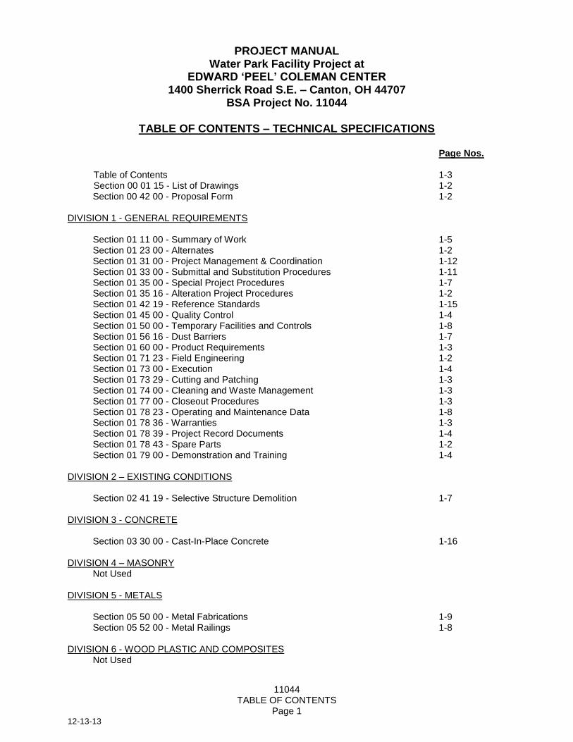
PROJECT MANUAL Water Park Facility Project at
EDWARD ‘PEEL’ COLEMAN CENTER 1400 Sherrick Road S.E. – Canton, OH 44707
BSA Project No. 11044
TABLE OF CONTENTS – TECHNICAL SPECIFICATIONS
Page Nos.
Table of Contents 1-3 Section 00 01 15 - List of Drawings 1-2
Section 00 42 00 - Proposal Form 1-2 DIVISION 1 - GENERAL REQUIREMENTS
Section 01 11 00 - Summary of Work 1-5 Section 01 23 00 - Alternates 1-2 Section 01 31 00 - Project Management & Coordination 1-12 Section 01 33 00 - Submittal and Substitution Procedures 1-11 Section 01 35 00 - Special Project Procedures 1-7 Section 01 35 16 - Alteration Project Procedures 1-2 Section 01 42 19 - Reference Standards 1-15 Section 01 45 00 - Quality Control 1-4 Section 01 50 00 - Temporary Facilities and Controls 1-8 Section 01 56 16 - Dust Barriers 1-7 Section 01 60 00 - Product Requirements 1-3 Section 01 71 23 - Field Engineering 1-2 Section 01 73 00 - Execution 1-4 Section 01 73 29 - Cutting and Patching 1-3 Section 01 74 00 - Cleaning and Waste Management 1-3 Section 01 77 00 - Closeout Procedures 1-3 Section 01 78 23 - Operating and Maintenance Data 1-8 Section 01 78 36 - Warranties 1-3 Section 01 78 39 - Project Record Documents 1-4 Section 01 78 43 - Spare Parts 1-2 Section 01 79 00 - Demonstration and Training 1-4
DIVISION 2 – EXISTING CONDITIONS Section 02 41 19 - Selective Structure Demolition 1-7
DIVISION 3 - CONCRETE
Section 03 30 00 - Cast-In-Place Concrete 1-16
DIVISION 4 – MASONRY Not Used
DIVISION 5 - METALS
Section 05 50 00 - Metal Fabrications 1-9 Section 05 52 00 - Metal Railings 1-8
DIVISION 6 - WOOD PLASTIC AND COMPOSITES Not Used

11044 TABLE OF CONTENTS
Page 2 12-13-13
DIVISION 7 - THERMAL AND MOISTURE PROTECTION
Section 07 10 00 - Dampproofing and Waterproofing 1-4 Section 07 84 00 - Firestopping 1-6 Firestopping Details - Concrete 1-44 Firestopping Details – Top of Wall 1-6 Section 07 92 00 - Joint Sealants 1-8
DIVISION 8 - OPENINGS Not Used
DIVISION 9 - FINISHES
Section 09 90 00 - Painting 1-9 Section 09 90 00b - Paint Schedule 1-6
DIVISION 10 - SPECIALTIES
Section 10 44 00 - Fire Protection Specialties 1-2
DIVISION 11 - EQUIPMENT Not Used DIVISION 12 - FURNISHINGS
Not Used
DIVISION 13 - SPECIAL CONSTRUCTION Section 13 11 00 – Water Spraygrounds 1-15
DIVISION 14 - CONVEYING EQUIPMENT Not Used
DIVISION 15 THROUGH 20 Not Used
DIVISION 21 - FIRE SUPPRESSION Not Used DIVISION 22 - PLUMBING See Drawings DIVISION 23 - HEATING VENTILATING AND AIR CONDITIONING See Drawings DIVISION 24 THROUGH 25 Not Used DIVISION 26 - ELECTRICAL See Drawings DIVISION 27 - COMMUNICATIONS Not Used
11044 TABLE OF CONTENTS
Page 3 12-13-13
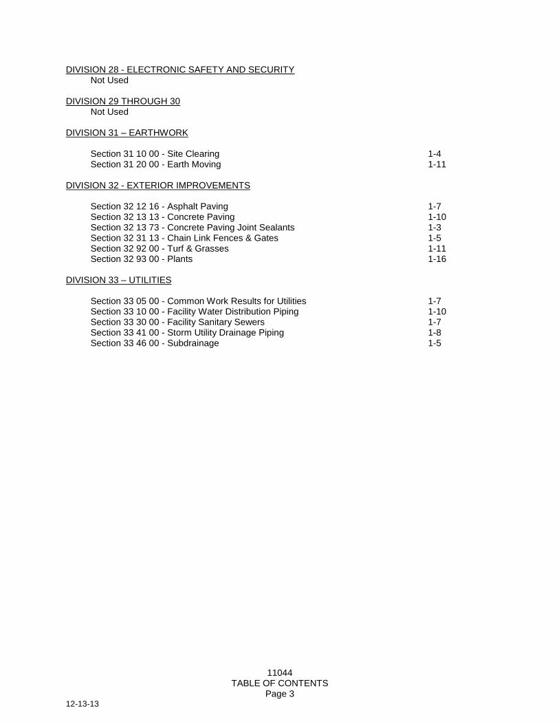
DIVISION 28 - ELECTRONIC SAFETY AND SECURITY Not Used DIVISION 29 THROUGH 30 Not Used
DIVISION 31 – EARTHWORK Section 31 10 00 - Site Clearing 1-4
Section 31 20 00 - Earth Moving 1-11
DIVISION 32 - EXTERIOR IMPROVEMENTS Section 32 12 16 - Asphalt Paving 1-7 Section 32 13 13 - Concrete Paving 1-10 Section 32 13 73 - Concrete Paving Joint Sealants 1-3 Section 32 31 13 - Chain Link Fences & Gates 1-5 Section 32 92 00 - Turf & Grasses 1-11
Section 32 93 00 - Plants 1-16
DIVISION 33 – UTILITIES
Section 33 05 00 - Common Work Results for Utilities 1-7 Section 33 10 00 - Facility Water Distribution Piping 1-10 Section 33 30 00 - Facility Sanitary Sewers 1-7
Section 33 41 00 - Storm Utility Drainage Piping 1-8 Section 33 46 00 - Subdrainage 1-5
11044 LIST OF DRAWINGS
00 01 15 - 1 12-13-13
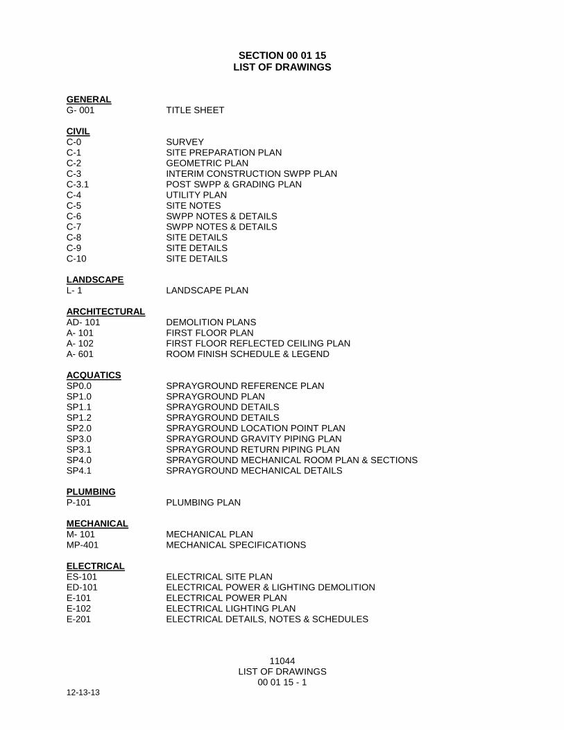
SECTION 00 01 15 LIST OF DRAWINGS
GENERAL G- 001 TITLE SHEET CIVIL C-0 SURVEY C-1 SITE PREPARATION PLAN C-2 GEOMETRIC PLAN C-3 INTERIM CONSTRUCTION SWPP PLAN C-3.1 POST SWPP & GRADING PLAN C-4 UTILITY PLAN C-5 SITE NOTES C-6 SWPP NOTES & DETAILS C-7 SWPP NOTES & DETAILS C-8 SITE DETAILS C-9 SITE DETAILS C-10 SITE DETAILS LANDSCAPE L- 1 LANDSCAPE PLAN ARCHITECTURAL AD- 101 DEMOLITION PLANS A- 101 FIRST FLOOR PLAN A- 102 FIRST FLOOR REFLECTED CEILING PLAN A- 601 ROOM FINISH SCHEDULE & LEGEND ACQUATICS SP0.0 SPRAYGROUND REFERENCE PLAN SP1.0 SPRAYGROUND PLAN SP1.1 SPRAYGROUND DETAILS SP1.2 SPRAYGROUND DETAILS SP2.0 SPRAYGROUND LOCATION POINT PLAN SP3.0 SPRAYGROUND GRAVITY PIPING PLAN SP3.1 SPRAYGROUND RETURN PIPING PLAN SP4.0 SPRAYGROUND MECHANICAL ROOM PLAN & SECTIONS SP4.1 SPRAYGROUND MECHANICAL DETAILS PLUMBING P-101 PLUMBING PLAN MECHANICAL M- 101 MECHANICAL PLAN MP-401 MECHANICAL SPECIFICATIONS ELECTRICAL ES-101 ELECTRICAL SITE PLAN ED-101 ELECTRICAL POWER & LIGHTING DEMOLITION E-101 ELECTRICAL POWER PLAN E-102 ELECTRICAL LIGHTING PLAN E-201 ELECTRICAL DETAILS, NOTES & SCHEDULES

11044 LIST OF DRAWINGS
00 01 15 - 2 12-13-13
E-202 ELECTRICAL DETAILS, NOTES & SCHEDULES E-301 ELECTRICAL ONE-LINE DIAGRAM E-401 ELECTRICAL SPECIFICATIONS E-402 ELECTRICAL SPECIFICATIONS
END OF SECTION

11044 PROPOSAL FORM - GENERAL
00 42 00 PF-1 12-13-13
PROPOSAL FORM – GENERAL CONTRACT
SUBMIT IN DUPLICATE
SUBMITTED BY: ________________________________________________________________
TO: City of Canton The Contract Office/Sixth Floor/Canton City Hall 218 Cleveland Avenue S.W. P.O. BOX 24218 Canton, Ohio 44702
Having read the Conditions of the Contract, the Bidding Requirements, and the Specifications in their entirety, and examined the Drawings entitled:
City of Canton
Water Park Facility Project at Edward “Peel” Coleman Center
BSA Job No. 11044
prepared by Braun & Steidl Architects, Inc., for the construction of said Project, and having inspected the site of and the conditions affecting and governing construction of said Project, the undersigned hereby proposes to furnish all materials and to perform all labor as specified and as shown for the following sum:
ITEM 1A. BASE BID - GENERAL CONTRACT –
ALL LABOR AND MATERIALS, for the sum of ...................... $ _________________________
Sum in words: _______________________________________________________________
ITEM 1B. PERFORMANCE BOND AND MATERIAL AND LABOR PAYMENT BOND -
Total, for the Sum of .................................................. ………...$ _________________________
Sum in words: _______________________________________________________________
Note: Above amount shall be included in Base Bid Item No. 1A
ITEM 1C. ALTERNATE G1: Standard Duty Asphalt Bike Path.
Total, for the Sum of………...................................................$ __________________________
Sum in words: _______________________________________________________________
ITEM 1D. ALTERNATE G2: Heavy Duty Asphalt Drive.
Total, for the Sum of..............................................................$ __________________________
Sum in words: _______________________________________________________________

11044 PROPOSAL FORM - GENERAL
00 42 00 PF-2 12-13-13
ITEM 1E. ALTERNATE SP1: 2-5 Year Old Spray Ground Area.
Total, for the Sum of…………………………………………….$ __________________________
Sum in words: _______________________________________________________________
ITEM 1G. ALTERNATE E1: New Exterior Site Lighting
Total, for the Sum of…………………………………………… $ __________________________
Sum in words: _______________________________________________________________
ITEM 2. TIME OF COMPLETION
From the date that the Contract is signed (Notice To Proceed), the undersigned hereby agrees to complete all the work shown and specified for acceptance by the Owner (Substantial Completion) by the following date:
May 23, 2014 (110 Calendar Days).
(Project is required to be operational on May 26, 2014)
ITEM 3. ACKNOWLEDGMENT
Bidder hereby acknowledges receipt of Addendum (Addenda) Nos.
____________________________________________________ (List all numbers received).
END OF SECTION
11044 SUMMARY OF WORK
01 11 00-1 12-13-13
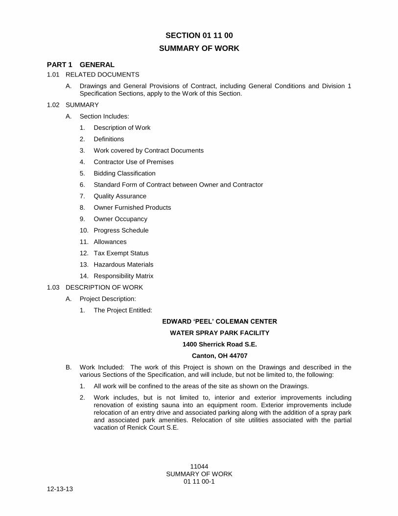
SECTION 01 11 00
SUMMARY OF WORK
PART 1 GENERAL
1.01 RELATED DOCUMENTS
A. Drawings and General Provisions of Contract, including General Conditions and Division 1 Specification Sections, apply to the Work of this Section.
1.02 SUMMARY
A. Section Includes:
1. Description of Work
2. Definitions
3. Work covered by Contract Documents
4. Contractor Use of Premises
5. Bidding Classification
6. Standard Form of Contract between Owner and Contractor
7. Quality Assurance
8. Owner Furnished Products
9. Owner Occupancy
10. Progress Schedule
11. Allowances
12. Tax Exempt Status
13. Hazardous Materials
14. Responsibility Matrix
1.03 DESCRIPTION OF WORK
A. Project Description:
1. The Project Entitled:
EDWARD ‘PEEL’ COLEMAN CENTER
WATER SPRAY PARK FACILITY
1400 Sherrick Road S.E.
Canton, OH 44707
B. Work Included: The work of this Project is shown on the Drawings and described in the various Sections of the Specification, and will include, but not be limited to, the following:
1. All work will be confined to the areas of the site as shown on the Drawings.
2. Work includes, but is not limited to, interior and exterior improvements including renovation of existing sauna into an equipment room. Exterior improvements include relocation of an entry drive and associated parking along with the addition of a spray park and associated park amenities. Relocation of site utilities associated with the partial vacation of Renick Court S.E.

11044 SUMMARY OF WORK
01 11 00-2 12-13-13
3. Alternate Work includes all necessary labor & materials for the construction of:
a. Alternate G1: Standard Duty Asphalt Bike Path, extent as indicated on the drawings.
b. Alternate G2: Heavy Duty Asphalt Drive, extent as indicated on the drawings.
c. Alternate SP1: All work associated with 2-5 YEAR OLD SPRAYGROUND AREA, extent as indicated on the drawings. Base Bid to included stub-out for water from building, see plans for limits.
d. Alternate E1: Exterior Site Lighting (Poles Base Wire), extent as indicated on the drawings
C. The Drawings and Specifications are complementary and what is required by any one shall be as binding as if required by all.
1.04 DEFINITIONS
A. Furnish: Purchase and deliver to project site, ready for installation.
B. Install: Unpack, assemble, set in final position, fasten in place, make final connections, clean, adjust, and leave ready for use.
C. Provide: Furnish and install.
D. Receive: Accepting a delivery.
E. Final Connections: Complete plumbing, mechanical, and electrical connections as required and recommended by manufacturer for optimum operation of equipment.
F. Drawings, Use of: Do not scale the Drawings. If the Contractor chooses to calculate measurements by scaling the Drawings, it is at his own risk and is not considered to be an accurate measurement. The Contractor is responsible for the accuracy of measurements, elevations, lines, and grades of the Work.
1.05 WORK COVERED BY CONTRACT DOCUMENTS
A. The work of this Project is shown on the Drawings and described in the various Sections of the Specification.
B. The Drawings and Specifications are complementary and what is required by any one shall be as binding as if required by all.
1.06 CONTRACTOR USE OF PREMISES
A. General: General Contractor shall limit their use of the premises to construction activities in areas indicated.
1. During the entire construction period, the Contractor shall provide access as required to maintain continuous operation of adjacent areas of the building and site, including required exit-ways for both vehicular and pedestrian traffic.
2. Confine operations to areas within Contract limits indicated. Portions of the site beyond areas in which construction operations are indicated are not to be disturbed.
3. Keep driveways and entrances serving the premises clear and available to the Owner at all times. Do not use these areas for parking or storage of materials. Schedule deliveries to minimize space and time requirements for storage of materials and equipment on site.
4. General Contractor to coordinate with Owner the use of the premises for available on-site Contractor parking.
B. General Contractor shall assume full responsibility for protection and safe keeping of products under this Specification.
11044 SUMMARY OF WORK
01 11 00-3 12-13-13
1.07 BIDDING CLASSIFICATION
A. This project shall be performed under the following Prime Contracts:
1. General Contractor: The General Construction Contract includes architectural, civil, and structural construction plus other construction operations traditionally recognized as General Construction. It also includes administrative and coordination responsibilities.
B. A Project Labor Agreement (PLA) will not be required for this contract.
1.08 STANDARD FORM OF CONTRACT BETWEEN OWNER AND CONTRACTOR
A. Contract Description: Construct the Work under the Contract as furnished by Owner.
1.09 QUALITY ASSURANCE
A. Qualifications of Contractors: In order to assure that Bidders are qualified to perform the work bid upon, the Owner, at his sole discretion, may require Bidder to submit a list of five (5) similar projects which have been completed by the Bidder. Such list shall include descriptions of the work performed and a specific person (reference) whom the Owner may contact. If Owner requires such list, submit promptly within five (5) days. Non-compliance may cause rejection of Bid.
B. It is the intent of the Owner and the Project Manual to conform with the AMERICANS WITH DISABILITIES ACT OF 1991.
1.10 OWNER FURNISHED PRODUCTS
A. Owner's Responsibilities:
1. Arrange for manufacturers' warranties, inspections, and service.
B. Contractor's Responsibilities:
1. Repair or replace items damaged after receipt.
C. Owner Furnished Products to be installed/relocated by the Contractor:
1. Items as indicated on drawings to be removed from present location and to be relocated on site during this contract.
1.11 OWNER OCCUPANCY
A. Owner will occupy areas of the premises during entire construction period for conduct of his normal operations. Cooperate with Owner in scheduling operations to minimize conflict and to facilitate Owner usage.
1. Maintain access to the existing parking lots by Owner, Employees, and patrons for the duration of construction. Coordinate with Owner for areas to be designated as contractor parking.
2. Coordinate with Owner to maintain access to existing adjacent facilities via alternate’s routes if required.
3. All locations of material transportation equipment, including cranes, hoists, etc., shall be as approved by the General Contractor, Owner and Architect.
1.12 PROGRESS SCHEDULE
A. A progress schedule listing the major items of work and dates of completion shall be submitted in bar-graph form for the Architect's and Construction Manager’s approval no more than 10 days after the date of the Owner's award of Contract. This schedule shall be updated before every construction meeting.

11044 SUMMARY OF WORK
01 11 00-4 12-13-13
B. Material Delivery Schedule:
1. The Contractors shall include in their Bid, all premium costs to obtain or divide orders for materials as required to meet all completion dates of Base Bid.
1.13 ALLOWANCES
A. Allowances include direct costs only. All costs for overhead and profit are included in the Base Bid.
1.14 TAX EXEMPT STATUS
A. City of Canton is exempt from the Ohio Retail Sales Tax, the Federal Manufacturer's Excise Taxes, (Refund of the Manufacturer's Tax, where paid, can be obtained by the manufacturer by filing I.R.S. Form 843), the Federal Transportation Tax where it is the consignee of the material shipped. City of Canton assumes no responsibility as to which items are tax exempt or not exempt. Tax ID No. shall be furnished upon request to successful bidder.
1.15 HAZARDOUS MATERIALS
A. In the event the Contractor encounters material reasonably believed to contain asbestos or other hazardous materials which have not been identified or rendered harmless, the Contractor shall immediately stop work in the area affected and report the condition to the Owner in writing. The work in the affected area shall be resumed in the absence of mold or asbestos, as verified by the Owner.
B. To the fullest extent permitted by law, the Owner shall indemnify and hold harmless the Contractor, Engineer, Architect and Architect's consultants and agents and employees of any of them from and against claims, damages, losses, and expenses, including, but not limited to, attorney's fees arising out of or resulting from performance of the work in the affected area if, in fact, the material is asbestos and has not been rendered harmless, provided that such claim, damage, loss, or expense is attributable to bodily injury, sickness, disease, or death, or to injury to or destruction of tangible property (other than the work itself), including loss of use resulting there from, but only to the extent caused in whole or in part by negligent acts or omissions of the Owner, anyone directly or indirectly employed by the Owner or anyone for whose acts the Owner may be liable, regardless of whether or not such claim, damage, loss, or expense if caused in part by a party indemnified hereunder. Such obligation shall not be construed to negate, abridge, or reduce other rights or obligations of indemnity which would otherwise exist as to a part or person described in this Subparagraph.
PART 2 PRODUCTS Not Used
PART 3 EXECUTION Not Used
PART 4 RESPONSIBILITY MATRIX
4.01 ITEMS TO BE FURNISHED BY OWNER / INSTALLED BY OWNER (FBO / IBO)
A. General:
1. Custodial equipment other than items noted
2. Recycle bins
3. Security system, cameras, & cabling
4. Telephones / data equipment
5. IT equipment

11044 SUMMARY OF WORK
01 11 00-5 12-13-13
4.02 ITEMS TO BE FURNISHED BY OWNER / INSTALLED BY CONTRACTOR (FBO/IBC)
A. None
4.03 ITEMS TO BE FURNISHED BY CONTRACTOR / INSTALLED BY CONTRACTOR (FBC/IBC)
A. Signage:
1. Misc. traffic and parking signage
END OF SECTION 01 11 00

11044 ALTERNATES
01 23 00 - 1 12-13-13
SECTION 01 23 00
ALTERNATES
PART 1 GENERAL
1.01 SUMMARY
A. Section Includes:
1. This Section includes administrative and procedural requirements for Alternates.
2. Identification and Description of Alternate Work.
B. Related Requirements
1. Notice to Bidders
2. Proposal Form
3. Summary of Work
1.02 DEFINITIONS
A. Alternate: An amount proposed by bidders and stated on the Bid Form for certain work defined in the Bidding Requirements that may be added to or deducted from the Base Bid amount if Owner decides to accept a corresponding change either in the amount of construction to be completed or in the products, materials, equipment, systems, or installation methods described in the Contract Documents.
1. The cost or credit for each alternate is the net addition to or deduction from the Contract Sum to incorporate alternate into the Work. No other adjustments are made to the Contract Sum.
1.03 PROCEDURES
A. Alternates will be exercised at the option of the Owner.
B. Coordinate related work and modify surrounding work as required to complete the Work, including changes under each Alternate, when acceptance is designated in Agreement.
C. The work to be executed under this Section shall include all labor, material, and equipment to add or deduct the Alternates as identified in this Specification.
D. All work that is added by Alternates shall match the Base Bid work.
E. Contractor shall request from their subcontractors, amounts to be added to or deducted from their Base Bids for Alternates affecting their section of work.
1.04 ALTERNATES - GENERAL
A. A "Schedule of Alternates" is included at the end of this Section. Refer to related Specification Sections and Drawings for the requirements for materials and methods necessary to achieve the work described under each Alternate.
B. Include as part of each Alternate, miscellaneous devices, accessory objects, and similar items incidental to or required for a complete installation, whether or not mentioned as a part of the Alternate.
C. Award of any, all, or none of the Alternates shall not affect the time proposal as established by each Contractor on the Bid Form.
D. Alternates may be awarded in any order and any combination, as solely determined by the Owner and the Architect.
11044 ALTERNATES
01 23 00 - 2 12-13-13
1.05 NOTIFICATION
A. Immediately following the Award of Contract, each Contractor shall prepare and distribute to each of his parties involved, notification of the status of each Alternate.
PART 2 PRODUCTS Not Used
PART 3 EXECUTION
3.01 SCHEDULE OF ALTERNATES
A. Alternate G1: Standard Duty Asphalt Bike Path, extent as indicated on the drawings.
B. Alternate G2: Heavy Duty Asphalt Drive, extent as indicated on the drawings.
C. Alternate SP1: All work associated with 2-5 YEAR OLD SPRAYGROUND AREA, extent as indicated on the drawings. Base Bid to included stub-out for water from building, see plans for limits.
D. Alternate E1: Exterior Site Lighting (Poles Base Wire), extent as indicated on the drawings
END OF SECTION 01 23 00

11044 PROJECT MANAGEMENT & COORDINATION
01 31 00-1 12-13-13
SECTION 01 31 00
PROJECT MANAGEMENT & COORDINATION
PART 1 GENERAL
1.01 SUMMARY
A. Section Includes
1. Coordination
2. Communication
3. Coordination Drawings
4. Superintendent
5. Staff Names
6. Progress Meetings
7. Reports
8. Contractor Use of Site and Premises
9. Owner Occupancy
10. Existing Buildings
11. Utility Outage Restrictions
12. Control of Hazardous Energy
13. Construction Utilities and Use of Facilities
14. Environmental Requirements
B. Related Sections
1. Section 00 72 13 - General Conditions
2. Section 01 11 00 - Summary of Work
3. Section 01 35 16 – Alteration Project Procedures
4. Section 01 50 00 - Construction Facilities and Controls
1.02 COORDINATION
A. Coordinate construction operations included in different Sections of the Specifications to ensure efficient and orderly installation of each part of the Work. Coordinate construction operations included under different Sections that are dependent on each other for proper installation, connection, and operation.
B. Coordination: The Contractor shall coordinate its construction operations with those of other entities to ensure efficient and orderly installation of each part of the Work. The Contractor shall coordinate its operations with operations, included in different Sections, that depend on each other for proper installation, connection, and operation.
1. Schedule construction operations in sequence required to obtain the best results where installation of one part of the Work depends on installation of other components, before or after its own installation.
2. Coordinate installation of different components with subcontractors to ensure maximum accessibility for required maintenance, service, and repair.
3. Make adequate provisions to accommodate items scheduled for later installation.
4. Where availability of space is limited, coordinate installation of different components to ensure maximum performance and accessibility for required maintenance, service, and

11044 PROJECT MANAGEMENT & COORDINATION
01 31 00-2 12-13-13
repair of all components, including, but not limited to, plumbing, fire protection, HVAC, electrical and telecommunications.
5. Coordination activities of Contractor include, but are not limited to, the following:
a. Provide overall coordination of the scheduling of the Work and the Work itself.
1) Subcontractors shall cooperate with and assist the General Contractor in the preparation of construction progress and procedures, schedule of product deliveries, and their effect on the overall project progress and completion. All Contractors shall cooperate in getting their Work and the Work of their subcontractors completed according to the schedule. Each subcontractor shall immediately notify the General Contractor of a delay in delivery of products or the scheduled date of completion that may affect the total progress of construction
b. Coordinate shared access to workspaces.
c. Provide overall coordination of temporary facilities and controls.
d. Coordinate and schedule interruptions of permanent and temporary utilities, including those necessary to make connections for temporary services.
e. Coordinate construction and operations of the Work with work performed by each Contractor, Owner’s Material Supplier, and Owner’s schedules and activities.
f. Coordinate sequencing and scheduling of the Work. Include the following:
1) Refer to the "General Conditions" for additional requirements.
g. Coordinate sequence of activities to accommodate tests and inspections, and coordinate scheduling of tests and inspections.
h. Provide progress cleaning of common areas and coordinate progress cleaning of areas or pieces of equipment where more than one contractor has worked.
i. Coordinate cutting and patching.
j. Coordinate protection of the Work.
k. Coordinate firestopping.
l. Coordinate completion of all punch list items for all contractors.
m. Coordinate preparation of Project Close-out Procedures.
6. Refer to the General Conditions for additional requirements.
C. Conservation: Coordinate construction activities to ensure that operations are carried out with consideration given to conservation of energy, water, and materials.
1. Salvage materials and equipment involved in performance of, but not actually incorporated into, the Work. Refer to other Sections for disposition of salvaged materials that are designated as Owner’s property.
D. Contractor’s Environmental Manager: Refer to Section 01 11 00 “Summary of Work” for requirements.
1.03 ADMINISTRATIVE PROCEDURES
A. Coordinate scheduling and timing of administrative procedures with other activities to avoid conflicts and ensure orderly progress of the Work. Such activities include; but are not limited to, the following:
1. Preparation of Contractor’s Construction Schedules

11044 PROJECT MANAGEMENT & COORDINATION
01 31 00-3 12-13-13
2. Preparation of the Schedule of Values
3. Installation and Removal of Temporary Facilities and Controls
4. Delivery and Processing of Submittals
5. Progress Meetings
6. Project Closeout Activities
1.04 COMMUNICATIONS
A. Project Identification:
1. All correspondence pertaining to this Project shall contain the Project Name and the date written or prepared.
2. All written communication including transmittals, submittals, Requests for Information (RFI), electronic / e-mail correspondence, facsimiles (fax), and other forms of correspondence shall identify the Project with the Project Name and the Owner’s Project Number, as well as the A/E’s Project Number in the subject, title or reference line or elsewhere in the text where appropriate.
B. The Contractor shall forward all communications to the Owner through the Architect.
1.05 COORDINATION DRAWINGS
A. In addition to the Coordination Drawing requirements in the General Conditions, Contractors shall provide the following information:
1. Content: Project-specific information, drawn accurately to scale. Do not base Coordination Drawings on reproductions of the Contract Documents or standard printed data. Include the following information, as applicable:
a. Indicate functional and spatial relationships of components of architectural, structural, civil, mechanical, and electrical systems.
b. Indicate required installation sequences.
c. Indicate dimensions shown on the Contract Drawings and make specific note of dimensions that appear to be in conflict with submitted equipment and minimum clearance requirements. Provide alternate sketches to the Owner’s Representative for resolution of such conflicts. Minor dimension changes and difficult installations will not be considered changes to the Contract.
2. Sheet Size: At least 8-1/2 by 11 inches but no larger than 30 by 42 inches.
3. Reviewed Coordination Drawings will be required as part of the Operations and Maintenance Manuals.
B. Refer to individual Sections for Coordination Drawing requirements for Work in those Sections.
1.06 SUPERINTENDENT
A. The Contractor's Superintendent shall be ”non-working”, and at the job site full-time continuously from the start of the job.
1. The term "full-time" is hereby defined as "each working hour each working day". The Contractor will not be permitted to maintain "part-time" Superintendent.
2. The Superintendent shall not be removed from the job until after final acceptance of the work or until completion of all "Punch List" items.
3. Refer to the General Conditions for additional requirements.

11044 PROJECT MANAGEMENT & COORDINATION
01 31 00-4 12-13-13
1.07 STAFF NAMES
A. Key Personnel Names: Within 10 days of the Notice to Proceed, the Contractor shall submit to the A/E, and to the Owner, a list of ALL personnel assignments, including superintendent and other personnel in attendance at Project site.
1. Identify individuals and their duties and responsibilities; list addresses and telephone numbers, including home and office telephone numbers for Project Managers and Superintendents.
a. Emergency Contacts: The list shall contain the telephone, cell phone, and/or pager numbers required for the Owner to contact Contractor’s personnel on a 24-hour basis, for the duration of the contract. Failure of these contact persons to be both available and authorized to handle emergency situations arising at the project site may result in assignment of Owners costs to the responsible Contractor. The list shall include:
1) Local Police and Building Security, and fire department.
2) Contractor's home office.
3) Owner's office and mobile.
4) All other Prime Contractors home office and field mobile phones
5) Any other important numbers given by the Owner’s Representative.
2. The Contractor shall maintain a contact list of all personnel for the project on-site at all times.
3. Post copies in the Project meeting room, the field office, and at each temporary telephone.
1.08 PROGRESS MEETINGS
A. General: Schedule and conduct meetings and conferences at Project site as required by the General Conditions.
1. The Contractor shall have the responsible Project Manager and/or other person of Authority attend every Project Progress Meeting and Special Meeting, unless prior approval for excuse is given by the Owner.
2. Failure to attend required meetings shall be grounds for deduct change order for every occurrence for time and wages, including travel, expenses, overhead and profit of the person responsible to attend unless a qualified, informed, and capable substitute is provided. Determination of deduct change orders and/or suitability of the substitute shall be under the prerogative of the Owner.
B. Pre-construction Conference: The A/E will schedule a preconstruction conference before starting construction, at a time convenient to the Owner. Hold the conference at Project site or another convenient location. Conduct the meeting to review responsibilities and personnel assignments.
1. Attendees: Owner’s Representative, A/E and their consultants; Contractor and its superintendent; major Subcontractors; suppliers; and other concerned parties shall attend the conference. All participants at the conference shall be familiar with the Project and authorized to conclude matters relating to the Work.
2. Agenda: Discuss items of significance that could affect progress, including the following:
a. Tentative construction schedule.
b. Phasing, including scaffolding work.
c. Critical work sequencing and long-lead items.

11044 PROJECT MANAGEMENT & COORDINATION
01 31 00-5 12-13-13
d. Designation of key personnel and their duties.
e. Schedule of Values
f. Procedures for processing field decisions and Change Orders.
g. Procedures for requests for interpretations (RFIs).
h. Procedures for testing and inspecting.
i. Procedures for processing Applications for Payment.
j. Distribution of the Contract Documents.
k. Submittal procedures.
l. Preparation of Record Documents.
m. Closeout procedures
n. Use of the premises and existing utilities.
1) Office and storage areas.
2) Owner's requirements.
o. Work restrictions.
p. Owner's occupancy requirements.
q. Responsibility for temporary facilities and controls.
r. Construction waste management and recycling.
s. Parking availability.
t. Office, work, and storage areas.
u. Equipment deliveries and priorities.
v. Safety and First aid.
w. Security.
x. Progress cleaning.
y. Working hours.
z. Toilet Facilities
3. Minutes: The A/E will prepare and distribute meeting minutes.
C. Project Coordination Meetings: Conduct a Coordination Meeting at Project site before each Progress Meeting.
1. Refer to General Conditions for requirements.
D. Progress Meetings: Conduct progress meetings at weekly intervals, or more frequent as determined by the A/E. Actual dates for the progress meetings will be determined at the Pre-construction Conference.
1. Agenda: Review and correct or approve minutes of previous progress meeting. Review other items of significance that could affect progress. Include topics for discussion as appropriate to status of Project.
a. Construction Schedule: Review progress since the last meeting. Determine whether each activity is on time, ahead of schedule, or behind schedule, in relation to Construction Progress Schedule. Determine how construction behind schedule will be expedited; secure commitments from parties involved to do so. Discuss
11044 PROJECT MANAGEMENT & COORDINATION
01 31 00-6 12-13-13
whether schedule revisions are required to ensure that current and subsequent activities will be completed within the Contract Time.
b. Review schedule of activities for next period.
c. Discuss and assemble resolutions for expediting work behind schedule.
1) Refer to the General Conditions for the process of expediting and completing work that is behind schedule.
d. Review present and future needs of each entity present, including the following:
1) Two-week and one month look ahead.
2) Interface requirements.
3) Sequence of operations.
4) Status of submittals.
5) Deliveries.
6) Off-site fabrication.
7) Access.
8) Site utilization.
9) Temporary facilities and controls.
10) Work hours.
11) Hazards and risks.
12) Progress cleaning.
13) Quality and work standards.
14) Status of correction of deficient items.
15) Field observations.
16) Requests for interpretations (RFI’s).
17) Status of Bulletins.
18) Pending changes.
19) Status of Field Work Orders (FWO’s)
20) Status of Change Orders.
21) Pending claims and disputes.
22) Documentation of information for payment requests.
2. Minutes: The A/E will assemble and distribute the meeting minutes.
3. Schedule Updating: Refer to the General Conditions.
E. Pre-Installation Conferences: Conduct Pre-Installation Conferences at before each construction activity that requires coordination with other construction as equipment as delineated in specific Specification Sections, Divisions 02 through 33.
1. Attendees: The Prime Contractor, installer and representatives of manufacturers and fabricators involved in or affected by the installation, and its coordination or integration with other materials and installations that have preceded or will follow, shall attend the meeting. The Owner shall schedule conferences and advise the A/E of scheduled meeting dates.
11044 PROJECT MANAGEMENT & COORDINATION
01 31 00-7 12-13-13
2. Agenda: Review the progress of other construction activities and preparations for the particular activity under consideration at each pre-installation conference, including requirements for the following:
a. Contract Documents.
b. Options.
c. Related Change Orders.
d. Purchases.
e. Deliveries.
f. Shop drawings, product data, and quality control samples.
g. Review of mock-ups.
h. Time schedules.
i. Weather limitations.
j. Manufacturer's recommendations.
k. Warranty requirements.
l. Coordination with other materials.
m. Compatibility of materials.
n. Acceptability of substrates.
o. Temporary facilities.
p. Space and access limitations.
q. Governing regulations.
r. Safety.
s. Inspection and testing requirements.
t. Required performance results.
u. Recording requirements.
v. Protection.
3. Do not proceed with the installation if the conference cannot be successfully concluded. Initiate whatever actions are necessary to resolve impediments to the performance of the Work and reconvene the conference at the earliest feasible date.
F. Special Meetings: Conduct the following Special Meetings before each construction activity that requires coordination with other construction:
1. On projects involving facilities management or temperature control systems, the Prime Contractor shall schedule and coordinate a preliminary submittal review meeting. The purpose of this meeting is to review the shop drawings with the Owner, the Engineer
responsible for the review and approval of the submittals, and the contractor/subcontractor responsible for preparing the submittals. A similar meeting will be scheduled and coordinated to review the proposed programming prior to actual system programming.
2. On projects involving air and/or water balancing, the Contractor shall schedule and coordinate a pre-balancing meeting with the Owner, the Engineer, and the balancing contractor to review the proposed balancing procedures prior to the start of any testing or balancing work.
11044 PROJECT MANAGEMENT & COORDINATION
01 31 00-8 12-13-13
3. On projects involving waterproofing, or roofing the Contractor shall schedule and coordinate a pre-installation meeting with the Owner, A/E and the subcontractor to review the procedures and requirements prior to the start of work.
4. On projects involving new elevator installation or existing elevator modifications, a pre-installation meeting and a pre-inspection meeting shall be held with subcontractors. The Contractor shall prepare meeting minutes with action items, and responsibilities assigned to insure that the installation of the elevator and all trades associated with its function are completed and ready for the inspection.
1.09 REPORTS
A. Weekly Reports:
1. Refer to the General Conditions for requirements.
1.10 CONTRACTOR USE OF SITE AND PREMISES
A. The Contractor shall limit construction operations to areas noted on the Drawings.
B. Contractors’ employees and agents are authorized access to the project work area. They are prohibited from entering or otherwise using Owner’s buildings or facilities, which are outside the Project area, unless required to conduct project related business or as otherwise authorized by the Owner. Violations may be cause for immediate termination from the project of the individuals committing such behavior
C. The Contractor and his employees shall be subject to and shall at all times conform to the Owner’s rules and requirements for the protection of the buildings, the equipment, the project materials, the Owner’s employees, and the public.
1. The Contractor is charged with the protection of adjacent structures, site improvements and landscaping.
D. The Contractor is responsible for their subcontractors, vendors, and delivery services.
E. The Contractor shall not permit dumping of materials, chemicals, washout or other improper use of drainage systems for cleaning and disposal purposes
F. The Contractor shall secure all equipment and materials at the end of every work day. The Contractor shall provide and maintain all items of protection in best condition for the duration of the project.
G. The Owner shall designate areas for parking, storage, and construction trailers.
1. Parking shall be subject to current rules and regulations to the building Owner’s Operations.
a. Parking and loading will be limited to the building site when space permits. Otherwise, parking will be as directed by the Owner.
b. Contractor parking spaces for the project will be assigned by the Owner. Contractors shall refer to the Summary and/or Site Plan for locations and quantity of spaces assigned to each Contractor. Parking Services will assign designated contractor parking areas based on the time of year, project size and location. These locations may not be adjacent to the construction sites or within walking distance. Contractors are responsible for providing transportation and time required for transportation of workers to/from the construction site. All costs associated with parking and transit shall be included in the Bid.
2. No contractor affiliated vehicle is to be operated on sidewalks at any time without specific approval by the Owner.
H. A minimum of two (2) weeks’ notice to the Owner’s Representative shall be provided for all street blocking outside of the construction limits.

11044 PROJECT MANAGEMENT & COORDINATION
01 31 00-9 12-13-13
1. The Contractor will be required to post warning signs that comply with the Ohio Department of Transportation Highway Signage Manual. All temporary signs shall be removed immediately after need has been removed.
a. Coordinate all street & sidewalk interruptions with the Owner.
b. All associated fees are the responsibility of the Contractor that requires the interruption.
I. Material Delivery and Storage:
1. The Contractor shall, as soon as the Contract has been awarded and the Project started, contact the Owner’s Representative in regard to coordinating space for material storage and staging area as designated in the Summary of Work, Drawings and Division 01.
a. Limited vehicular access as required by the phasing of construction and as approved by the Owner will be permitted on accessible sides of the building.
b. The Contractor will restore all damaged items upon project completion.
c. Storage of all construction equipment, tools, supplies and materials shall be within the confines of the construction area.
d. Storage of materials within the building shall not obstruct any of the work, or entrances and exits of the building. Material storage within the building must be agreeable to all contractors.
1) Any keying or door hardware changes required for storage permitted in the Owner’s facilities shall be paid for by the Contractor but installed by the Owner.
e. Protection of Owner’s equipment stored on site is required of all Contractors, similar to the protection afforded other Contractor's materials and equipment.
f. The Contractor must be personally responsible for the receiving of all materials. It shall be the responsibility of Contractors to direct and address all deliveries to the construction site and not the Owner. The Owner will not sign for, pay for, or otherwise accept materials for the Contractors and may direct the delivery service to return to sender.
g. Temporary storage facilities shall be provided to protect equipment and/or materials delivered to the job site which may be damaged by exposure to weather. It shall be the Contractor's responsibility to provide all labor and materials necessary to provide such protection.
J. The Contractor shall provide all necessary traffic and pedestrian control to ensure the health and welfare of the public during the disruption of the building corridors from the performance of the work required under this contract.
K. All Contractors shall exercise control over all trucks and equipment using public roads and the Owner’s property to preclude spillage, tracking of dirt or debris thereon. Should spillage occur, that Contractor is held to promptly clean and remove same.
1. Mud from the construction site shall be removed from public and Owner’s roads daily. Failure to remove mud promptly could result in roads being cleaned by the Owner at the responsible Contractor's expense.
2. Repair of damage to streets, roads, walks, or other facilities shall be the responsibility of the Contractor causing the damage, at no expense to the City of Akron, or Owner. Work shall be performed to the satisfaction of the Owner's representative.
1.11 OWNER OCCUPANCY
A. Contractors shall cooperate with the Owner to minimize interference and to facilitate Owner’s operations.
11044 PROJECT MANAGEMENT & COORDINATION
01 31 00-10 12-13-13
B. Schedule all work to accommodate Owner occupancy and operations. Construction work shall not interfere with the Owner's operations. There will be no compromise on this requirement.
1. The Owner reserves the right to suspend or limit noisy or disruptive construction activities that interfere with normal Owner operations. Refer to Section 01 11 00 “Summary of Work” for additional requirements.
2. Unless otherwise approved, the contractor shall maintain access for the disabled at all times around the project site. Access shall include roads, pedestrian ways, lighting, and temporary ramps and handrails in accordance with ADA regulations.
C. Owner will occupy the building during the life of the project. It is the intent of the Owner to maintain use of the existing buildings, roads, pedestrian walks, parking lots and other service areas around the construction area during the construction period. Close coordination and scheduling will be required for this work.
1. Contractors are to cooperate with the Owner by keeping materials and construction operations during construction within the work area.
a. The Contractor shall obtain the approval of the Owner before starting any work that may affect any adjacent areas of the building.
D. Any damage to areas outside of the Project Area, resulting from the construction operation or caused by the Contractor's personnel, shall be restored at the Contractor's expense to the satisfaction of the Owner’s Representative and the A/E.
1. Site protection of the existing equipment from dust and debris will be required to isolate the new work area from the rest of the building or other buildings by whatever means possible, including the need for air filtration units. If dust is distributed throughout the existing facility, the contractor who failed in dust control will be required to clean the facility back to its original condition, in a time frame established by the Owner.
2. Unless otherwise approved by the Owner, the Contractor shall ensure that all existing site and security lighting and traffic signaling is maintained throughout the project. In the event of damage to an existing electrical feed to site or security lighting, repairs or the installation of temporary lighting will be undertaken immediately and all associated costs shall be borne by the responsible contractor
E. Work that is classified as causing a disruption to the Owner’s operations will be performed at times other than normal work hours and will be required to be coordinated with the Owner’s Representative.
1.12 EXISTING BUILDING
A. All entrances and exits for the public must be maintained during construction periods, unless shown otherwise on the Drawings.
B. All measurements given in the Documents shall be verified at the existing building before any work is executed by the Contractor, and any discrepancy between the Documents and the actual conditions shall be reported immediately to the A/E.
C. The Contractors shall include in their proposals the cost of all premium time required for work necessary to prevent interruption of building services or the disruption of the Owner's personnel during their working hours. Refer to the General Conditions for additional requirements.
1. Where parts of the Project require interruption of electrical service, the Contractor shall make arrangements with the Owner's representative to establish times at which the work can be done.
2. Extra precautions shall be taken if interruption of service to occupied areas is necessary, including building power or any electrically operated system.

11044 PROJECT MANAGEMENT & COORDINATION
01 31 00-11 12-13-13
3. In order to ensure that the above requirement is met, the Contractor shall take positive steps to prevent dust, noise, disruption of utilities, and similar hazards resulting from construction work from either interfacing with or damaging the Owner's property.
4. The Contractors shall neither use, nor have access to any building, except as specifically required to complete construction work, and only as scheduled with the Owner.
5. All workmen shall clean their shoes before entering existing buildings.
6. Any damage to areas outside of the Project Area, resulting from the construction operation or caused by the Contractor's personnel, shall be restored at the Contractor's expense to the satisfaction of the Owner.
D. Dust Control and Partitions:
1. Refer to Section 01 50 00 “Construction Facilities and Controls”.
1.13 UTILITY OUTAGE RESTRICTIONS
A. Definitions:
1. Switching Outage: An outage required to transfer utility loads from one source (e.g. distribution feeder) to another for installation of new equipment (e.g. switchgear) or for rework of building services. Switching outages shall be restricted to a maximum of one (1) hour in length unless written authorization is received from the Owner.
2. Construction Outage: An outage due to any other circumstance besides a switching outage. The utility service shall be restored within twelve (12) hours or less as scheduled elsewhere in the Construction Documents.
3. Extended Outage: The Owner may make special arrangements and grant special permission to allow a Construction Outage to exceed the twelve (12) hour restriction.
B. The Contractor will be working around existing buildings which are occupied. The Contractor shall maintain service of power, light, water, sewage, gas, steam, telephone, and data at all times unless temporary outages have been approved by the Owner.
C. If construction activities require an outage in any of the Owner’s utilities, the Contractor shall submit an outage request to Owner for their review and approval. This outage request shall be submitted ten (10) days prior to the proposed outage, and an approval must be received at least seven (7) days prior to the proposed outage before it may be scheduled.
D. All utility outages shall be scheduled outside Normal Working Hours unless permitted elsewhere in the Construction Documents. Outages may be scheduled on Sundays and holidays to minimize utility interruptions. The Contractor’s bid shall reflect any additional costs associated with outage work scheduled outside of Normal Working Hours.
1. Normal Working Hours for the Owner are defined as 8:00 AM to 5:00 PM, Monday through Friday.
E. Duration of outages shall be limited by the Owner during their review and approval of the Contractor’s outage request. Specific requirements are identified elsewhere in the Construction Documents. Typically, utility outages are not permitted to extend into the next Normal Working Hour.
F. If the Contractor cannot restore utility services within the limits of the approved outage, the Contractor may be assessed liquidated damages. In the case of electrical construction, the Contractor shall always be prepared to supply 120 volt, 20 amp backup electrical power to campus critical loads using the Contractor’s own portable generators, if necessary. The Contractor shall provide all conductor, conduit, disconnects, cords, and overcurrent protection as required when connecting temporary generation equipment. Critical loads will be identified and a list provided to the Contractor prior to each approved outage.
11044 PROJECT MANAGEMENT & COORDINATION
01 31 00-12 12-13-13
G. The Contractor shall anticipate work conditions (e.g. power and lighting interruptions) during utility outages and is responsible for making temporary arrangements (e.g. portable generator) to provide a safe work environment. A description of the temporary arrangements shall be included in the Contractor’s outage request and must be approved by and Owner.
H. Switching Operations:
1. Utility switching by the Contractor shall be done under the direction of the Owner. Except in the case of an emergency, the Contractor is not permitted to switch utilities without the Owner’s approval.
1.14 CONTROL OF HAZARDOUS ENERGY
A. The Contractor is not permitted to work on any energized circuits or active systems. Disconnect switches and valves shall be opened prior to the starting of work.
B. The Contractor shall comply with lockout/tagout requirements of OSHA 29 CFR 1910.147. The Contractor shall submit lockout/tagout procedures for review by the University as well as training certifications for employees prior to starting any work.
C. The control of hazardous energy procedures and training plans shall include the isolation or inactivation of hazardous energy sources before performing work thereon. A hazardous energy source is defined as a machine or equipment item with the potential for causing injury by unexpected energizing, startup, or stored energy release.
D. The procedures shall consist of placing appropriate tags on each item of equipment and each system component indicating its current status and requiring mandatory clearances from designated personnel to operate, energize, or remove from service the equipment or systems.
E. Current certification of training accomplishments is required. Certification shall include employee names and training completion dates.
F. Coordinate lockout/tagout operations with the Owner and Facilities personnel. Notifications of status and requests for clearances for operations are required. The procedures established shall be strictly followed.
1.15 CONSTRUCTION UTILITIES AND USE OF FACILITIES
A. Refer to Section 01 50 00 "Construction Facilities & Controls " for additional requirements.
B. Telephone services will not be available for use by the Contractor.
1.16 ENVIRONMENTAL REQUIREMENTS
A. The Contractor is required to comply with all applicable federal, state, and local environmental laws and regulations, including but not limited to those dealing with the protection of air, water, natural and cultural resources and noise pollution management.
B. The Contractor is required to comply with all applicable federal, state, and local laws and regulations dealing with the proper management and disposal of solid, toxic, and hazardous wastes. The Contractor shall be responsible for obtaining all necessary disposal permits and licenses prior to commencement of work.
1.17 HAZARDOUS MATERIALS
A. Each Contractor shall comply with all laws concerning hazardous materials. Hazardous material shall be disposed in a legal manner. MSDS sheets for hazardous materials shall be filed at the Contractor's job site office and as otherwise required by law.
B. Refer to the General Conditions for additional requirements.
PART 2 PRODUCTS (NOT USED)
PART 3 EXECUTION (NOT USED) END OF SECTIONS 01 31 00
11044 SUBMITTALS AND SUBSTITUTION PROCEDURES
12-13-13
SECTION 01 33 00
SUBMITTALS AND SUBSTITUTION PROCEDURES
PART 1 GENERAL
1.01 SUMMARY
A. Wherever possible throughout the Contract Documents, the minimum acceptable quality of workmanship and materials has been defined either by manufacturer's name and catalog number or reference to recognized industry standards.
B. To ensure that the specified products are furnished and installed in accordance with the design intent, procedures have been established for advance submittal of design data for its review and approval or rejection by the Architect.
C. This Section specifies administrative and procedural requirements for submittals required for performance of the work, including:
1. Contractor's Construction Schedule
2. Shop Drawings, Product Data, and Samples
3. Certificates
4. Manufacturer Installation Instructions
5. Substitution Procedures
6. Manuals
7. Miscellaneous Submittals
D. Related Sections:
1. Contractual Requirements for Submittals: General Conditions
a. Two (2) copies of all Submittals, plus number of copies to be returned to Contractor, shall be submitted unless otherwise specified.
b. Provide additional copies as required for use in Project Record Documents.
2. Section 01 77 00 – Closeout Procedures
3. Individual Submittals Required: Pertinent Sections of these Specifications.
1.02 SUBMITTAL PROCEEDURES
A. Coordination: Coordinate preparation and processing of Submittals with performance of construction activities. Transmit each Submittal sufficiently in advance of performance of related construction activities to avoid delay.
1. Coordinate each Submittal with fabrication, purchasing, testing, delivery, other Submittals and related activities that require sequential activity.
2. Coordinate transmittal of different types of Submittals for related elements of the work so processing will not be delayed by the need to review Submittals concurrently for coordination.
a. The Architect reserves the right to withhold action on a Submittal requiring coordination with other Submittals until related Submittals are received.
b. No extension of Contract Time will be authorized because of failure to transmit Submittals to the Architect sufficiently in advance of the work to permit processing.

11044 SUBMITTALS AND SUBSTITUTION PROCEDURES
12-13-13
B. Deliver Submittals to the Architect.
C. Submittal Preparation: Place a permanent label or title block on each Submittal for identification. Indicate the name of the entity that prepared each Submittal on the label or title block.
1. Provide a space approximately 10" x 10" on the label or beside the title block on shop drawings to record the Contractor's and Architect review and approval markings and the action taken.
2. Include the following information on the label for processing and recording action taken:
a. Project Name
b. Name of the Owner
c. Date
d. Name and Address of Architect
e. Name and Address of Contractor
f. Name and Address of Subcontractor or Vendor
g. Location Where Item is to be used
h. Name of Manufacturer
i. Drawing Number and Detail References, as Appropriate
j. Certification by the Contractor
D. Submittal Transmittal: Package each Submittal appropriately for transmittal and handling. Transmit each Submittal from Contractor to Architect. Submittals received from sources other than the Contractor will be returned without action.
1. Transmit each submittal to the Architect with “AIA Document G810 - Transmittal Letter”.
2. Sequentially number the transmittal form. Revise submittals with original number and a sequential alphabetic suffix.
3. Identify Project, Contractor, Subcontractor or supplier; pertinent Drawing and detail number, and Specification Section number, as appropriate.
4. On the transmittal, record relevant information and requests for data. On the form, or separate sheet, record deviations from Contract Document requirements, including minor variations and limitations. Include Contractor's certification that information complies with Contract Document requirements.
5. After Architect’s review of Submittal, revise and resubmit as required, identifying changes made since previous Submittal.
6. When resubmittal is required for any reason, transmit under new letter of transmittal, indicating by reference to a previous Submittal that this is a Resubmittal.
a. Identify on submittal all changes made since previous submission.
E. Distribute copies of reviewed Submittals to concerned persons. Instruct recipients to promptly report any inability to comply with provisions.
F. All Submittals shall bear the stamp of approval of the General Contractor submitting same as evidence that they have been checked by them, or they will be rejected.
1. Must be signed or initialed certifying that review, verification of Products required, field dimensions, adjacent construction Work, and coordination of information, is in accordance with the requirements of the Work and Contract Documents.
11044 SUBMITTALS AND SUBSTITUTION PROCEDURES
12-13-13
G. Schedule submittals to expedite the Project, and deliver to Architect. Coordinate submission of related items. Instruct parties to promptly report any inability to comply with provisions.
1.03 CONTRACTOR'S CONSTRUCTION SCHEDULE
A. Bar-Chart Schedule: The Contractor for General Construction shall prepare a fully-developed, horizontal bar-chart type Contractor's construction schedule, with a copy to each subcontractor. Submit within 10 days of the date established for the Notice to Proceed. No work is to begin on Project site until schedule has been approved by the Architect and the Owner.
1. Provide a separate time bar for each significant construction activity. Provide a continuous vertical line to identify the first working day of each week. Use the same breakdown of units of the work as indicated in the "Schedule of Values".
2. Within each time bar, indicate estimated completion percentage in 10 percent increments. As work progresses, place a contrasting mark in each bar to indicate Actual Completion.
3. Prepare the schedule on a sheet, or series of sheets, of stable transparency, or other reproducible media, of sufficient width to show data for the entire construction period.
4. Secure time commitments for performing critical elements of the work from parties involved. Coordinate each element on the schedule with other construction activities. Include minor elements involved in the sequence of the work. Show each activity in proper sequence. Indicate graphically, sequences necessary for completion of related portions of the work.
5. Indicate completion in advance of the date established for Substantial Completion. Indicate Substantial Completion on the schedule to allow time for the Architect's procedures necessary for certification of Substantial Completion.
6. If adjustments are necessary for sequencing and coordination of the work, the Contractor for General Construction shall arrange a meeting with the other contractors at the earliest possible date. At this meeting, each contractor shall negotiate reasonable adjustments to their schedules.
B. Schedule Updating: Revise the schedule after each meeting or activity where revisions have been recognized or made. Issue the updated schedule concurrently with report of each meeting.
1.04 SHOP DRAWINGS
A. Where shop drawings are required, submit newly prepared information drawn to accurate scale. Highlight, encircle, or otherwise indicate deviations from the Contract Documents. Do not reproduce Contract Documents or copy standard information as the basis of shop drawings. Standard information prepared without specific reference to the Project is not considered shop drawings.
1. Contractor may purchase on request for purposes of base plan information only electronic files at a cost of $100.00 per file, contingent upon the signing a CADD File Use Agreement, provided by the Architect or their Consultant.
B. Shop Drawings shall be drawn at a scale to clearly indicate all of the above conditions and allow for corrections or modifications which the Architect may wish to make. The Architect shall be the sole judge as to the acceptability of manufacturer's literature and catalog sheets as shop drawings.
C. Shop Drawings shall clearly indicate all dimensional data for all parts of the item; types and materials for all connections; finishes; the exact relation of the item to adjacent materials and equipment in the completed structure including clearance, any necessary isolation, and fastening methods and devices; and mechanical and electrical connections.
11044 SUBMITTALS AND SUBSTITUTION PROCEDURES
12-13-13
D. Shop Drawings include fabrication and installation drawings, setting diagrams, schedules, patterns, templates, and similar drawings. Include the following information:
1. Dimensions
2. Identification of Products and Materials Included
3. Compliance with Specified Standards
4. Notation of Coordination Requirements
5. Notation of Dimensions Established by Field Measurement
E. Sheet Size: Except for templates, patterns, and similar full-size drawings, submit shop drawings on sheets at least 8-1/2" x 11", but no larger than 36" x 48".
F. Submit in the form of one reproducible transparency and one opaque reproduction, or three opaque reproductions plus required amount to be returned to Contractor. After review, reproduce and distribute to appropriate parties.
G. Do not permit shop drawing copies, without an appropriate final "Action" marking by the Architect, to be used in connection with the work.
H. The Contractors shall be responsible for distribution of additional prints to vendors, etc.
I. Maintain approved copies of shop drawings, as returned, at the Project site throughout the course of construction.
J. Refer to General Conditions for additional requirements.
1.05 COORDINATION DRAWINGS
A. Comply with requirements in Division 1 Section "Project Management and Coordination."
1.06 PRODUCT DATA
A. Where product data is required, collect product data into a single submittal for each element of construction or system. Product data includes printed information such as manufacturer's installation instructions, catalog cuts, standard color charts, roughing-in diagrams and templates, standard wiring diagrams and performance curves. Where product data must be specially prepared because standard printed data is not suitable for use, submit as "shop drawings."
1. Mark each copy to show applicable choices and options. Where printed product data includes information on several products, some of which are not required, mark copies to indicate the applicable information. Include the following information:
a. Manufacturer's Printed Recommendations
b. Compliance with Recognized Trade Association Standards
c. Compliance with Recognized Testing Agency Standards
d. Application of Testing Agency Labels and Seals
e. Notation of Dimensions Verified by Field Measurement
f. Notation of Coordination Requirements
g. Type and Model Numbers
2. Do not submit product data until compliance with requirements of the Contract Documents has been confirmed.

11044 SUBMITTALS AND SUBSTITUTION PROCEDURES
12-13-13
B. Distribution: Furnish copies of final Submittal to installers, subcontractors, suppliers, manufacturers, fabricators, and others required for performance of construction activities. Show distribution on transmittal forms.
1. Do not proceed with installation until a copy of product data applicable is in the installer's possession.
2. Do not permit use of unmarked copies of product data in connection with construction.
3. Maintain approved copies of product data, as returned, at the Project site throughout the course of construction.
1.07 SAMPLES
A. Where samples are required, submit full-size, fully fabricated samples cured and finished as specified and physically identical with the material or product proposed. Samples include partial sections of manufactured or fabricated components, cuts or containers of materials, full color-range sets, and swatches showing color, texture, and pattern.
1. Mount, display, or package Samples in the manner specified to facilitate review of qualities indicated. Include the following:
a. Generic Description of the Sample
b. Sample Source
c. Product Name or Name of Manufacturer
d. Compliance with Recognized Standards
e. Availability and Delivery Time
2. Colors: Unless the precise color and pattern is specifically described in the Contract Documents, whenever a choice of color or pattern is available in a specified product, submit accurate color charts and pattern charts to the Architect for their review and selection.
3. Submit Samples for review of kind, color, pattern, and texture for a final check of these characteristics with other elements and for a comparison of these characteristics between the final Submittal and the actual component as delivered and installed.
a. Where variation in color, pattern, texture, or other characteristics are inherent in the material or product represented, submit multiple units (not less than 3) that show approximate limits of the variations.
b. Refer to other Specification Sections for requirements for samples that illustrate workmanship, fabrication techniques, details of assembly, connections, operation, and similar construction characteristics.
c. Refer to other Sections for samples to be returned to the Contractor for incorporation in the work. Such samples must be undamaged at time of use. On the transmittal, indicate special requests regarding disposition of sample submittals.
4. Preliminary Submittals: Where samples are for selection of color, pattern, texture, or similar characteristics from a range of standard choices, submit a full set of choices for the material or product.
a. Preliminary Submittals will be reviewed and returned with the Architect's mark indicating selection and other action.
5. Maintain sets of samples, as returned, at the Project site for quality comparisons throughout the course of construction.
a. Unless noncompliance with Contract Document provisions is observed, the Submittal may serve as the final Submittal.

11044 SUBMITTALS AND SUBSTITUTION PROCEDURES
12-13-13
b. Sample sets may be used to obtain final acceptance of the construction associated with each set.
B. Distribution of Samples: Prepare and distribute additional sets to subcontractors, manufacturers, fabricators, suppliers, installers, and others as required for performance of the work.
1. Field Samples specified in individual Sections are special types of samples. Field samples are full-size examples erected on site to illustrate finishes, coatings, or finish materials and to establish the standard by which the work will be judged.
a. Comply with submittal requirements to the fullest extent possible. Process transmittal forms to provide a record of activity.
1.08 CERTIFICATES
A. Insurance Certificates and Bonds: Prepare written information indicating current status of insurance or bonding coverage. Include name of entity covered by insurance or bond, limits of coverage, amounts of deductibles, if any, and term of the coverage.
B. When specified in individual Specification Sections, submit certification by manufacturer to Architect, in quantities specified for product data. Prepare written statements on manufacturer's letterhead certifying that manufacturer complies with requirements. Include evidence of manufacturing experience where required.
C. Indicate material or Product conforms to or exceeds specified requirements. Submit supporting reference data, affidavits, and certifications as appropriate.
D. Certificates may be recent or previous test results on material or product, but must be acceptable to Architect.
E. Welding Certificates: Prepare written certification that welding procedures and personnel comply with requirements. Submit record of Welding Procedure Specification (WPS) and Procedure Qualification Record (PQR) on AWS forms. Include names of firms and personnel certified.
F. Installer Certificates: Prepare written statements on manufacturer's letterhead certifying that Installer complies with requirements and, where required, is authorized for this specific Project.
1.09 MANUFACTURER INSTALLATION INSTRUCTIONS
A. When specified in individual Specification Sections, submit printed instructions for delivery, storage, assembly, installation, start-up, adjusting, and finishing to Architect.
B. Indicate special procedures, perimeter conditions requiring special attention, and special environmental criteria required for application or installation.
C. Manufacturer's Field Reports: Prepare written information documenting factory-authorized service representative's tests and inspections. Include the following, as applicable:
1. Name, address, and telephone number of factory-authorized service representative making report.
2. Statement on condition of substrates and their acceptability for installation of product.
3. Statement that products at Project site comply with requirements.
4. Summary of installation procedures being followed, whether they comply with requirements and, if not, what corrective action was taken.
5. Results of operational and other tests and a statement of whether observed performance complies with requirements.
6. Statement whether conditions, products, and installation will affect warranty.

11044 SUBMITTALS AND SUBSTITUTION PROCEDURES
12-13-13
1.10 TEST REPORTS
A. Material Test Reports: Prepare reports written by a qualified testing agency, on testing agency's standard form, indicating and interpreting test results of material for compliance with requirements.
B. Pre-construction Test Reports: Prepare reports written by a qualified testing agency, on testing agency's standard form, indicating and interpreting results of tests performed before installation of product, for compliance with performance requirements.
C. Compatibility Test Reports: Prepare reports written by a qualified testing agency, on testing agency's standard form, indicating and interpreting results of compatibility tests performed before installation of product. Include written recommendations for primers and substrate preparation needed for adhesion.
D. Field Test Reports: Prepare reports written by a qualified testing agency, on testing agency's standard form, indicating and interpreting results of field tests performed either during installation of product or after product is installed in its final location, for compliance with requirements.
E. Product Test Reports: Prepare written reports indicating current product produced by manufacturer complies with requirements. Base reports on evaluation of tests performed by manufacturer and witnessed by a qualified testing agency, or on comprehensive tests performed by a qualified testing agency.
1.11 MISCELLANEOUS SUBMITTALS
A. Application for Payment: Comply with requirements in Division 1 Sections.
B. Schedule of Values: Comply with requirements in Division 1 Sections.
C. Subcontractor List: Prepare a written summary identifying individuals or firms proposed for each portion of the Work, including those who are to furnish products or equipment fabricated to a special design. Include the following information in tabular form:
1. Name, address, and telephone number of entity performing subcontract or supplying products.
2. Number and title of related Specification Section(s) covered by subcontract.
3. Drawing number and detail references, as appropriate, covered by subcontract.
D. Qualification Data: Prepare written information that demonstrates capabilities and experience of firm or person. Include lists of completed projects with project names and addresses, names and addresses of architects and owners, and other information specified.
E. Design Data: Prepare written and graphic information, including, but not limited to, performance and design criteria, list of applicable codes and regulations, and calculations. Include list of assumptions and other performance and design criteria and a summary of loads. Include load diagrams if applicable. Provide name and version of software, if any, used for calculations. Include page numbers.
F. Manufacturer's Instructions: Prepare written or published information that documents manufacturer's recommendations, guidelines, and procedures for installing or operating a product or equipment. Include name of product and name, address, and telephone number of manufacturer. Include the following, as applicable:
1. Prepare written and graphic instructions and procedures for operation and normal maintenance of products and equipment. Comply with requirements in Division 1 Section "Closeout Procedures and Operation and Maintenance Data."
2. Preparation of substrates.
3. Required substrate tolerances.
11044 SUBMITTALS AND SUBSTITUTION PROCEDURES
12-13-13
4. Sequence of installation or erection.
5. Required installation tolerances.
6. Required adjustments.
7. Recommendations for cleaning and protection.
G. Other required items indicated in individual Specification Sections.
1.12 CONTRACTOR’S REVIEW
A. Review each submittal and check for compliance with the Contract Documents. Note corrections and field dimensions. Mark with approval stamp before submitting to Architect.
1. Architect will not review submittals that do not bear Contractor's approval stamp and will return them without action.
B. Approval Stamp: Stamp each submittal with a uniform, approval stamp. Include Project name and location, submittal number, Specification Section title and number, name of reviewer, date of Contractor's approval, and statement certifying that submittal has been reviewed, checked, and approved for compliance with the Contract Documents.
1. Compliance with specified characteristics is the Contractor's responsibility
1.13 ARCHITECT'S ACTION
A. Except for Submittals for record, information or similar purposes, where action and return is required or requested, the Architect will review each Submittal, mark to indicate action taken, and return promptly.
B. Action Stamp: The Architect will stamp each Submittal with a uniform, self-explanatory action stamp. The stamp will be appropriately marked, as follows, to indicate the action taken:
1. Final Unrestricted Release: Where Submittals are marked "CONFORMS AS SUBMITTED", that part of the work covered by the Submittal may proceed, provided it complies with requirements of the Contract Documents. Final payment will depend upon that compliance.
2. Final-but-Restricted Release: When Submittals are marked "CONFORMS AS NOTED", that part of the work covered by the Submittal may proceed, provided it complies with notations or corrections on the Submittal and requirements of the Contract Documents. Final payment will depend on that compliance.
3. Returned for Resubmittal: When Submittal is marked "REVISE AND RESUBMIT", do not proceed with that part of the work covered by the Submittal, including purchasing, fabrication, delivery, or other activity. Revise or prepare a new Submittal in accordance with the notations. Resubmit without delay. Repeat, if necessary, to obtain a different action mark.
a. Do not permit submittals marked "REVISE AND RESUBMIT" to be used at the Project site or elsewhere where work is in progress.
4. Other Action: Where a Submittal is primarily for information or record purposes, special processing or other activity, the Submittal will be returned marked "ACTION NOT REQUIRED".
PART 2 PRODUCTS
2.01 SUBSTITUTIONS
A. Source Limitations: To the greatest extent possible for each unit of work, provide products, materials, or equipment of a singular generic kind from a single source.
11044 SUBMITTALS AND SUBSTITUTION PROCEDURES
12-13-13
B. Compatibility of Options: Where more than one choice is available as options for Contractor's selection of a product or materials, select an option which is compatible with other products and materials already selected (which may have been from among options for those other products and materials). Total compatibility among options, if not assured by limitations within contract documents, must be provided by Contractor. Compatibility is a basic general requirement of product/material selections.
C. Architect’s Approval Required:
1. The Contract is based on the materials, equipment, and methods described in the Contract Documents.
2. The Contract Drawings and Specifications establish the "minimum standard of quality" each product and/or system must meet to be considered acceptable. Products of other manufacturers will be considered if the product and/or system meets or exceeds the "minimum standard of quality" established by the Contract Documents.
3. The Architect will consider proposals for substitutions under the "or approved equal" provision of materials, equipment, and methods by Addendum, prior to Bid due date, only when such proposals are accompanied by full and complete technical data and all other information required by the Owner and Architect to evaluate the proposed substitutions.
a. Proposals for substitutions are to be submitted by Bidders only. Submissions by other Contractors or suppliers will not be accepted.
b. It will be the responsibility of the submitting Contractor to prove equality.
c. The Submittal shall include a line-by-line, item-by-item description of the specified and proposed product.
4. Requests for substitutions must be submitted to the Architect NO later than fourteen (14) calendar days prior to Bid due date.
5. If the proposed product and/or system is acceptable as an equal, as herein described, an Addendum will be issued noting the specific items accepted.
6. DO NOT SUBSTITUTE MATERIALS, EQUIPMENT, OR METHODS UNLESS SUCH SUBSTITUTIONS HAVE BEEN SPECIFICALLY APPROVED FOR THIS WORK BY THE ARCHITECT, BY ADDENDUM.
D. "Or Approved Substitution" or "Or Approved Equal":
1. Where the phrase "or approved substitution" or "or approved equal" occurs in the Contract Documents, do not assume that material, equipment, or methods will be approved as equal by the Owner and Architect unless the item has been specifically approved for this work by the Owner and Architect.
a. Color choices as well as match to existing materials will be determining factors for approval.
2. The decision of the Architect will be final.
E. Availability of Specified Items:
1. Verify prior to bidding that all specified items will be available in time for installation during orderly and timely progress of the work.
2. In the event specified item or items will not be so available, so notify the Architect prior to the receipt of Bids.
3. Costs of delay caused on non-availability of specified items, when such delays could have been avoided by the Contractor, will be back-charged as necessary and shall not be borne by the Owner.

11044 SUBMITTALS AND SUBSTITUTION PROCEDURES
12-13-13
F. Whenever the Contractor secures approval for changing any items and such change involves a corresponding change or adjustment in any adjacent or related item, the responsibility for making the required change, or seeing that it is made, rests with the Contractor. The cost of these changes and/or adjustments shall be paid for by the Contractor unless it is otherwise agreed, in writing, at the time the change is approved. The acceptance of any change will not, in any way, relieve the Contractor from full compliance with the Contract Documents.
2.02 MANUALS
A. General: Where Manuals are required to be submitted covering items included in this work, prepare all such Manuals in durable plastic binders approximately 8-1/2 x 11 inches in size with at least the following:
1. Identification on or readable through the front cover stating the general nature of the Manual.
2. Neatly typewritten index near the front of the Manual furnishing immediate information as to location of all emergency data regarding the installation.
3. Complete instructions regarding operating and maintenance of all equipment involved.
4. Complete nomenclature of all replaceable parts, their part numbers, current cost, and name and address of nearest vendor of parts.
5. Copy of all guarantees and warranties issued.
6. Copy of approved shop drawing(s) with all data concerning all changes made during construction.
2.03 MISCELLANEOUS SUBMITTALS
A. Inspection and Test Reports Not Performed by Owner: Classify each inspection and test report as being either "shop drawings" or "product data" depending on whether the report is specially prepared for the Project or a standard publication of workmanship control testing at the point of production. Process inspection and test reports accordingly.
B. Warranties (Guarantees):
1. Categories of Specific Warranties: Warranties on the work are in several categories, including those of General Conditions, and including (but not necessarily limited to) the following specific categories related to individual units of work specified in sections of Divisions 02 through 33 of these Specifications.
a. Special Project Warranty (Guarantee): A warranty specifically written and signed by Contractor for a defined portion of the work and, where required, countersigned by Subcontractor, installer, manufacturer, or other entity engaged by Contractor.
b. Specified Product Warranty: A warranty which is required by Contract Documents, to be provided for a manufactured product incorporated into the work, regardless of whether manufacturer has published a similar warranty without regard for specific incorporation of product into the work, or has written and executed a special project warranty as a direct result of Contract Documents requirements.
c. Coincidental Product Warranty: A warranty which is not specifically required by Contract Documents (other than as specified in this Section), but which is available on a product incorporated into the work by virtue of the fact that manufacturer of product has published warranty in connection with purchases and uses of product without regard for specific applications, except as otherwise limited by terms of warranty.
C. Construction Photos: Email digital photos monthly, to the Architect.
1. Use minimum 3 megapixel type digital camera.
11044 SUBMITTALS AND SUBSTITUTION PROCEDURES
12-13-13
2. Provide necessary number of photographs, as required to document existing conditions to verify damage to adjacent property which may or may not have occurred during construction: Minimum 12 photos monthly.
PART 3 EXECUTION
3.01 COORDINATION OF SUBMITTALS
A. General: Prior to submittal for Architect's review, use all means necessary to fully coordinate all material, including the following:
1. Secure all necessary approvals from public agencies and others. Signify by stamp or other means that all required approvals have been obtained.
2. Clearly indicate all deviations from the Contract Documents.
B. The General Contractor shall submit a prioritized tabulation by date of Submittals required during the first 90 days of construction. List those Submittals required to maintain orderly progress of the work, and those required early because of long lead time for manufacture or fabrication.
1. These dates may be shown on Construction Project Schedule at Contractor's option.
3.02 TIMING OF SUBMITTALS
A. General:
1. Make all Submittals enough in advance of scheduled dates for installation to provide all required time for reviews for securing necessary approvals, for possible revision and Resubmittals, and for placing orders and securing delivery.
2. In scheduling, allow a minimum of twenty (20) full calendar days for the Architect’s initial review following receipt of the Submittals. Allow additional time if the Architect requires coordination with subsequent Submittals.
a. The Architect reserves the right to withhold action on a submittal requiring coordination with other submittals until all related Submittals are received.
b. If an Intermediate Submittal is necessary, process the same as the initial Submittal. Allow fourteen (14) calendar days for reprocessing each Submittal.
END OF SECTION 01 33 00
11044 SPECIAL PROJECT PROCEDURES
01 35 00 - 1 12-13-13
SECTION 01 35 00
SPECIAL PROJECT PROCEDURES
PART 1 GENERAL
1.01 RELATED DOCUMENTS
A. Drawings and General Provisions of Contract, including General and Supplementary Conditions and Division 01 Specification Sections, apply to work of this Section.
B. All Contractors shall be governed by all applicable Sections of these Documents with reference to their respective areas of work. It shall be the responsibility of the Contractors to apprise their Subcontractors and suppliers of these requirements.
1. The General Contractor and each subcontractor shall review all Sections of the Specifications and all Drawings and is responsible for all work pertaining to their trade regardless of Drawing or Section of Specifications it is written in.
C. Substitutions
1. The Specifications are based on the first product or manufacturer listed. Refer to Section 01 30 00, "Submittals and Substitutions", for instructions regarding substitutions, and "Approved Equals".
2. Deviations or substitutions not properly approved and authorized will be considered defective work. Payment will not be made for improper changes or substitutions.
D. Refer to Section 01 11 00 Summary of Work for additional Project contacts.
1.02 GENERAL
A. The Contractor and each subcontractor affirmatively represents that they are skilled and experienced in the performance of work as required by this Project and in the use and interpretation of Drawings and Specifications such as those included in the Contract Documents; that they have carefully reviewed the Drawings and Specifications of this Project; and that their Contract is based solely on these Documents, not relying in any way on any explanation or interpretations - oral or written - from any other source. The Contractor agrees that it shall be conclusively presumed that the Contractor has exercised his aforementioned skill and experience and found the Drawings and Specifications sufficient and free from ambiguities, errors, or omissions for the purpose of determining its Contract for the performance of the work in conformity with the Drawings, Specifications, and all other Contract Documents.
B. Each Contractor shall provide sufficient and adequate labor, materials and construction equipment necessary to properly correlate all phases of the work to the end that the approved Progress Schedule can be adhered to and the Contract Completion date met.
C. Overtime Work
1. Unless noted otherwise, or so directed by the Architect or the Owner, The General Contractor is solely responsible for all required costs, including standby required by other trades, if Contractor works premium hours (after regular hours, weekends, holidays, etc.).
D. In no case shall any Contractor proceed with work uncertainty.
E. The Contractor will ensure that all the Contractor's and subcontractor’s employees, while working on the property, will not purchase, transfer, use or possess illegal drugs, or alcohol or abuse prescription drugs in any way.
1. No foul or profane language, loud music or other disturbances will be permitted or tolerated at anytime.

11044 SPECIAL PROJECT PROCEDURES
01 35 00 - 2 12-13-13
2. No guns, firearms, drugs or alcoholic beverages shall be permitted anywhere on the premises - including within any vehicles.
3. No smoking or use of tobacco in any form shall be permitted within any building.
1.03 COMMUNICATIONS
A. The Contractor shall forward all communications to the Owner through the Architect.
B. Request for Information (RFI) and Supplemental Instructions:
1. It shall be the Contractor's obligation to check the Contract Documents and to request of the Architect any clarification necessary and in time so as not to delay the progress of the Work.
1.04 ACCESS TO AND SECURITY OF SITE AND BUILDING
A. Access to and security of the Project site are the responsibility of the Contractor and not that of the Owner or the Architect.
1. All construction personnel shall protect work, existing facilities, and Owner's operations from unauthorized entry, vandalism, and theft.
2. In those areas where work occurs, access and egress shall be as directed by the Architect and working areas shall be confined to within a specific area as directed by the Architect.
3. Existing buildings adjoining the area of work, except those areas in which work is to occur, shall not be entered for any reason.
1.05 RELATIONS WITH ADJOINING PROPERTY OWNERS
A. To facilitate his work, the Contractor may choose to make necessary arrangements for use and subsequent rehabilitation of the adjoining Owner's property. Such arrangements are solely the Contractor's responsibility.
1.06 USE OF SITE
A. The Owner’s property can be used for limited parking, storage, and construction trailers, only in location as directed and approved by the Owner.
1. No contractor affiliated vehicle is to be operated on sidewalks at anytime without specific approval by the Owner.
2. Use only designated areas for parking and storage as directed by Owner.
B. Keep driveways and entrances serving the premises clear and available to the Owner at all times. Do not use these areas for parking or storage of materials. Schedule deliveries to minimize space and time requirements for storage of materials and equipment on site. Existing Fire Lanes shall not be blocked at any time.
C. A minimum of two (2) weeks notice to the Owner shall be provided for all street blocking outside of the construction limits.
D. Material Delivery and Storage:
1. The primary delivery and staging area will be as directed by the Owner. Limited vehicular access as required by the phasing of construction and as approved by the Architect will be permitted on accessible sides of the site. The General Contractor will restore all damaged items upon project completion.
2. It shall be the responsibility of the Contractor to direct all deliveries to the construction site and not the Architect, or the Owner.
a. Temporary storage facilities shall be provided to protect equipment and/or materials delivered to the job site which may be damaged by exposure to weather. It shall be the General Contractor's responsibility to provide all labor and materials necessary

11044 SPECIAL PROJECT PROCEDURES
01 35 00 - 3 12-13-13
to provide such protection. The Owner shall be consulted as to the "adequacy" of such temporary protection.
E. All Contractors shall exercise control over all trucks and equipment using public roads and the Owner's property to preclude spillage, tracking of dirt or debris thereon. Should spillage occur, that Contractor is held to promptly clean and remove same.
1. Mud from the construction site shall be removed from public and the Owner's roads daily. Failure to remove mud promptly could result in roads being cleaned by the Owner at the responsible Contractor's expense.
F. Towing On Site
1. The General Contractor is responsible for providing any temporary hardstands (granular material, crane mats, etc.) and towing equipment required to continue with work so as not to delay the Project.
1.07 EXISTING BUILDING
A. The Owner will occupy the existing building during the life of the Project. All work shall be scheduled at such time and in such a manner to minimize interference and inconvenience to the Owner. Contractors shall obtain the approval of the Owner’s Representative before starting any work within the building.
1. Construction work shall not interfere with the Owner’s operations. There will be no compromise on this requirement.
B. The Contractors shall, at all times, proceed in a manner to ensure that the Owner's personnel shall have full use of the building, including utilities, existing parking areas, and recreation fields. The Contractors shall include in their proposals the cost of all premium time required for work necessary to prevent interruption of building services or the disruption of the Owner’s personnel during their working hours.
1. Construction operations shall be reviewed by the Architect prior to commencement of the work.
2. Where parts of the Project require interruption of electrical service for rewiring and relighting, the Contractor shall make arrangements with the Architect to establish times at which the work can be done.
3. Extra precautions shall be taken if interruption of service to occupied areas is necessary, including building power or any electrically operated system.
4. In order to ensure that the above requirement is met, the Contractor shall take positive steps to prevent dust, noise, disruption of utilities, and similar hazards resulting from construction work from either interfacing with or damaging the Owner's furniture and equipment.
5. Protective measures shall be substantial and positive and subject to no element or risk. All protective measures shall be reviewed by the Architect before they are incorporated into the work.
6. Dust Control: Each Contractor is responsible to completely control dust during the performance of their work, including any and all necessary measures such as watering, etc. This also includes dust control during operations on the part of the Contractor in which services are provided by others. This cost is the responsibility of the Contractor.
7. All measurements given in the Documents shall be verified at the existing site before any work is executed by each Contractor, and any discrepancy between the Documents and the actual conditions shall be reported immediately to the Architect.
8. Any damage to areas outside of the Project area, resulting from the construction operation or caused by the Contractor's personnel, shall be restored to preconstruction condition at the Contractor's expense to the satisfaction of the Architect.

11044 SPECIAL PROJECT PROCEDURES
01 35 00 - 4 12-13-13
1.08 MEETINGS
A. Before any work is started, responsible representatives for the General Contractor, including his designated job superintendent for the Project, shall meet at the Site with the Architect and the Owner's representative to review the requirements and conditions under which the Project will be performed.
B. Progress meetings shall be held at the Site under the direction of the Architect. The General Contractor and other major subcontractors shall attend or be represented by someone fully empowered to speak for and commit them to any agreement reached.
1.09 EXAMINATION AND VERIFICATION OF THE SITE
A. All Contractors submitting proposals for this work shall first examine the site and all conditions thereon. All proposals shall take into consideration all such conditions as may affect the work under this Contract.
B. Grades, Lines, Levels, and Surveys: Verify all lines, levels, and dimensions as shown on the Drawings, and report any errors or inconsistencies discovered in the above to the Architect before commencing work.
C. Field Measurements: The General Contractor shall take measurements in the field to verify or supplement dimensions indicated on Drawings and shall be responsible for accurate fit of specified work. Any discrepancy between the Drawings and the actual conditions shall be reported immediately to the Architect.
1.10 PROTECTION
A. The General Contractor shall take all responsibility for the work, and take all precautions for preventing injuries to persons and property on or about the work; shall bear all losses resulting to him on account of the amount or character of the work, or because the nature of the ground on which the work is done is different from what was estimated or expected, or on account of the weather, floods, elements or other cause; and he shall assume the defense of, and indemnify and save harmless, the Owner and its individual officers and agents, from all claims relating to labor and materials furnished for the work, to inventions, patents and patent rights used in doing the work, to injuries to any person or corporation received or sustained by or from the Contractor and his employees in doing the work, or in consequence of any improper materials, methods and implements or labor used therein; and to any act, omission or neglect of the Contractor and his employees therein.
B. It shall be the responsibility of the General Contractor to see that all personnel comply with Chapter IC-3, Specific Safety Requirements of the Industrial Commission of Ohio Relating to Construction, and the latest Federal Regulations of the Department of Labor, Bureau of Labor Standards, and the Occupational Safety and Health Act (OSHA).
C. The General Contractor shall provide and maintain guard lights for all work at all barricades, railings, obstructions in the streets, roads, or sidewalks, and at all trenches or pits. Remove such work when directed after necessity for same ceases.
1. The General Contractor is responsible for all required OSHA temporary protection and barricades necessary for the completion of his work.
2. Any temporary fencing and sidewalk barricades required will be provided by the General Contractor.
D. Temporary removal and reinstallation required for access is the responsibility of each Contractor requiring such access.
E. The General Contractor will be held responsible for all of his work and materials provided for by the Plans and Specifications until the work is completed and accepted. All Contractors shall:

11044 SPECIAL PROJECT PROCEDURES
01 35 00 - 5 12-13-13
1. Provide temporary protection for installed products. Control traffic in immediate area to minimize damage.
2. Prohibit traffic and storage on waterproofed and roofed surfaces and on lawn and landscaped areas.
3. Remove temporary materials, equipment, services, and construction prior to Substantial Completion inspection.
4. Clean and repair damage caused by installation or use of temporary facilities.
5. The General Contractor shall take necessary precautions to protect the finished work of all trades and shall be responsible for any negligence on his part.
F. Weather Protection:
1. All Contractors shall at all times provide protection against weather -- rain, wind, storms, frost, or heat -- so as to maintain his work, materials, apparatus, and fixtures free from injury or damage. At the end of the day's work, all work likely to be damaged shall be covered.
2. During cold weather, all contractors shall protect the work from damage. If low temperatures make it impossible to continue operations safely in spite of cold weather precautions, the Contractor shall cease work.
3. Any work damaged by failure to provide above protection shall be removed and replaced with new work at the responsible contractor's expense.
G. Dust Control and Partitions:
1. The General Contractor is responsible to completely control dust during the performance of his work, including any and all necessary measures such as dust enclosures, proper ventilation, etc. This also includes dust control during operations on the part of the Contractor in which services are provided by others. This cost is the responsibility of the General Contractor.
H. Noise and Odor Control:
1. Contractor shall minimize noise and odor as required. Contractor shall notify the Property 24 hours in advance of any construction activities that will create excessive noise or odors for the purpose of rescheduling Work or providing notifications.
1.11 FIRE REGULATIONS AND EXTINGUISHERS
A. Free access shall be maintained at all times from the street to fire hydrants and to outside connections for standpipes. Fire doors shall be installed and in operation at the earliest possible time.
B. The General Contractor is responsible for fire extinguishers and fire protection for all work, equipment, offices, sheds, etc., as required by OSHA regulations.
C. Each contractor shall appoint one of his personnel who is continually employed on the job site (such as the Superintendent) whose additional duty it will be to act as fire warden for the project. The fire warden shall institute and vigorously enforce a program of fire safety for the project.
D. Where existing exits occur, they shall be fully maintained at all times and shall be kept free from materials, equipment, or other obstructions.
E. Each contractor shall maintain fire protection equipment, institute fire prevention measures, and direct the prompt removal of all unnecessary combustible material and waste. Each Contractor shall be responsible for the correct and safe use of soldering coppers, extension lights, flammable liquids, welding and metal cutting apparatus, wax pots, or other open flame tools. This type of work shall be done only when properly supervised and with adequate fire extinguishing equipment available.
11044 SPECIAL PROJECT PROCEDURES
01 35 00 - 6 12-13-13
F. Combustible materials shall not be stored in the building.
G. The use of wood scaffolding will not be allowed. No part of the building where scaffolding is in place shall be used for the storage of flammable materials of any kind. Temporary structures of combustible material shall be located not less than 30 feet from the building.
H. No smoking or use of tobacco in any form shall be permitted within the building or adjacent areas.
I. Paints, varnishes, volatile oils, etc., shall be stored in metal lockers or metal boxes with self-closing covers. Gasoline and other volatile and flammable liquids shall be stored in metal barrels well away from other structures or other combustible materials.
J. Special precautions shall be taken to reduce fire hazards where electric or gas welding or cutting work is done and suitable fire extinguishing equipment shall be maintained near such operations.
1.12 RESTORATION
A. Where existing properties, streets, paving, curbs, etc., are removed or damaged as a result of work operations, the responsible Contractor shall restore the foregoing items to match the original or as required by local authorities.
1.13 WATER CONTROL
A. All Contractors shall provide, operate, and maintain pumps or other equipment necessary to drain his work. Keep excavation pits, trenches, and ditches including the entire subgrade free of any water under any circumstances that may arise.
1.14 REMOVAL
A. Remove temporary materials, equipment, services, and construction prior to Substantial Completion inspection.
B. Clean and repair damage caused by installation or use of temporary facilities.
1.15 HAZARDOUS MATERIALS
A. The Contractor shall comply with all laws concerning hazardous materials. Hazardous material shall be disposed in a legal manner. MSDS sheets for hazardous materials shall be filed at the Contractor's job site office and as otherwise required by law.
1.16 WAIVERS OF LIEN
A. During the course of construction, partial Waivers of Lien may be required prior to payment. The Affidavits and Waivers of Lien shall be submitted with each Application for Payment and shall consist of affidavits from the General Contractor, each subcontractor, each sub-subcontractor, and each material supplier.
B. By submitting an Application for Payment, the General Contractor attests to the accuracy of the amounts requested, represents that the work has been satisfactorily executed in compliance with the Contract Documents and that it is entitled to the amounts shown. By submitting the second or any subsequent Application for Payment, the Contractor attests that it has paid all just claims for labor, materials, equipment, subcontracts or other expenses represented by all previous Applications for Payment for which payment has been received from the Owner.
C. Furnishing of Affidavits and Waivers of Lien, in forms as approved and when required by the Owner, shall be a prerequisite to the issuance of all Certificates for Payment.
D. Prior to making final payment to the General Contractor, final Waivers of Lien shall be submitted from each material and equipment supplier, each subcontractor, and each sub-subcontractor employed by the Contractor, as well as from the General Contractor.
11044 SPECIAL PROJECT PROCEDURES
01 35 00 - 7 12-13-13
PART 2 PRODUCTS: NOT USED
PART 3 EXECUTION: NOT USED
END OF SECTION 01 35 00

11044 ALTERATION PROJECT PROCEDURES
01 35 16-1 12-13-13
SECTION 01 35 16
ALTERATION PROJECT PROCEDURES
PART 1 GENERAL
1.01 SUMMARY
A. Section Includes:
1. Procedural Requirements
2. Rehabilitation and Renovations of Existing Materials
3. Installation of Products Removed in Section 02 42 19
B. Related Sections
1. Section 01 35 00 - Special Project Procedures
2. Section 01 50 00 - Temporary Facilities and Controls
3. Section 01 73 29 - Cutting and Patching
4. Section 02 41 19 - Selective Structure Demolition
PART 2 PRODUCTS
2.01 PRODUCTS FOR PATCHING AND EXTENDING WORK
A. New Materials: As specified in individual Sections.
B. Match existing products and work for patching and extending work.
C. Determine type and quality of existing products by inspection and any necessary testing, and workmanship by use of existing as a standard. Presence of a product, finish, or type of work, requires that patching, extending, or matching shall be performed as necessary to make the work complete and consistent with Specifications.
PART 3 EXECUTION
3.01 INSPECTION
A. Verify that demolition is complete and areas are ready for installation of new work.
B. Beginning of restoration work means acceptance of existing conditions.
3.02 PREPARATION
A. Cut, move, or remove items as necessary for access to alterations and renovations work; replace and restore at completion.
B. Remove unsuitable material not marked for salvage, such as rotted wood, rusted metals, and deteriorated masonry and concrete; replace materials as specified for finished work.
C. Remove debris and abandoned items from area and from concealed spaces.
D. Prepare surfaces and remove surface finishes to provide for proper installation of new work and new finishes.
E. Clean substrate surfaces prior to applying next material or substance.
F. Seal cracks or openings of substrate prior to applying next material or substance.
G. Apply any manufacturer’s required or recommended substrate primer, sealer, or conditioner prior to applying any new material or substance in contact or bond.

11044 ALTERATION PROJECT PROCEDURES
01 35 16-2 12-13-13
3.03 INSTALLATION
A. Coordinate work of alterations and renovations to expedite completion.
B. Remove, cut, and patch work in a manner to minimize damage and to provide means of restoring products and finishes to specified condition.
C. Refinish visible existing surfaces to remain to specified condition for each material with a neat transition to adjacent new finishes.
D. Install products as specified in individual Sections.
3.04 TRANSITIONS
A. Where new work abuts or aligns with existing, make a smooth and even transition. Patched work shall match existing adjacent work in texture and appearance.
B. When finished surfaces are cut so that a smooth transition with new work is not possible, terminate existing surface along a straight line at a natural line of division as approved by Architect.
3.05 ADJUSTMENTS
A. Where removal results in adjacent surfaces forming a change of plane of ¼ inch or more occurs, submit recommendation for providing a smooth transition for Architect review.
3.06 REPAIR OF DAMAGED SURFACES
A. Patch or replace portions of existing surfaces to remain which are damaged, lifted, discolored, or showing other imperfections where noted on Drawings.
B. Repair substrate prior to patching finish.
3.07 FINISHES
A. Finish surfaces as specified in individual Sections.
B. Finish patches to produce uniform finish and texture over entire area. When finish cannot be matched, refinish entire surface to nearest intersections.
END OF SECTION 01 35 16

11044 REFERENCE STANDARDS
01 42 19-1 12-13-13
SECTION 01 42 19
REFERENCE STANDARDS
PART 1 GENERAL
1.01 SUMMARY
A. Section Includes:
1. Reference Standards
1.02 QUALITY ASSURANCE
A. Conflicting Requirements: Where compliance with two or more standards is specified and the standards establish different or conflicting requirements for minimum quantities or quality levels, comply with the most stringent requirement. Refer uncertainties and requirements that are different, but apparently equal, to the Architect for a decision before proceeding.
1. Minimum Quantity or Quality Levels: The quantity or quality level shown or specified shall be the minimum provided or performed. The actual installation may comply exactly with the minimum quantity or quality specified, or it may exceed the minimum with reasonable limits. To comply with these requirements, indicated numeric values are minimum or maximum, as appropriate, for the context of the requirements. Refer uncertainties to the Architect for a decision before proceeding.
1.03 INDUSTRY STANDARDS
A. Reference Standards
1. Conform with the provisions or standards referenced in the sections of the Specifications with the same force and effect as if the Standards referenced were bound or copied directly into the section, except that:
a. Conform with more stringent provisions when contained elsewhere in the Contract Documents; and
b. Conform with the more stringent provision when two or more Standards are referenced; and
c. Conform with the more stringent provision when the Standard referenced and the governing regulations differ unless the governing regulation require conformance to the less stringent provision without exception.
2. Submit for clarification and conform to the decision of the Architect when the Standard referenced:
a. Presents options which have not specifically been selected in the Contract Documents; or
b. Contain provisions which conflict with other provisions in the Contract Documents; or
c. It is uncertain or not clear which of differing provisions is the more stringent.
3. Conform to the provisions of the most recent issue of the Standard referenced as of the date of the Contract Documents.

11044 REFERENCE STANDARDS
01 42 19-2 12-13-13
B. Abbreviations and Acronyms of Organizations
1. Abbreviations and Names: Trade association names and titles of general standards are frequently abbreviated. Where abbreviations and acronyms are used in the Specifications or other Contract Documents, they mean the recognized name of the trade association, standards-producing organization, authorities having jurisdiction, or other entity applicable to the context of the text provision. Refer to Gale Research’s “Encyclopedia of Associations” or Columbia Books’ “National Trade and Professional Associations of the U.S.,” which are available in most libraries.
2. The names, addresses, and telephone numbers given in the List of Organizations are subject to change and are believed to be, but are not assured to be, accurate and up to date as of the issue date of this Section.
3. List of Organizations: Certain Standards issued by the following organizations may be referenced in the Specifications. Copies may be obtained from the issuing organization.
AA The Aluminum Association, Inc. (703) 358-2967 1525 Wilson Blvd, Suite 600 www.aluminum.org Rossyln, Arlington, VA 22209 AABC Associated Air Balance Council (202) 737-0202 1518 K St., NW www.aabchq.com Washington, DC 20005 AAMA American Architectural Manufacturer's Association (847) 303-5664 1827 Walden Office Sq., Suite 550 www.aamanet.org Schaumburg, IL 60173 AASHTO American Association of State Highway and (202) 624-5800 Transportation Officials www.transportation.org 444 Capitol St., Suite 249 Washington, DC 20001 AATCC American Association of Textile Chemists and Colorists (919) 549-8141 P O Box 12215 AATCC Research Triangle Park, NC 27709 ACI American Concrete Institute (248) 848-3700 38800 Country Club Drive www.aci-int.org Fumington Hills, MI 48331 ACMA American Composites Manufacturers Association (703) 525-0511 1010 North Glebe Rd, Suite 450 ACMA Arlington, VA 22201 ACPA American Concrete Pipe Association (972) 506-7216 1303 West Walnut Hill Lane, Suite 305 www.concrete-pipe.org Irving, TX 75038-3008 ADC Air Diffusion Council (847) 706-6750 1901 N. Roselle Road, Suite 800 www.flexibleduct.org/ Schaumburg, IL 60195 AFPA American Forest & Paper Association (800) 878-8878 1111 Nineteenth Street, NW, Suite 800 AFPA Washington, DC 20036 AF&PA American Wood Council (202) 463-2766 1111 Nineteenth Street, NW, Suite 800 AF&PA Washington, DC 20036
11044 REFERENCE STANDARDS
01 42 19-3 12-13-13
AGA American Gas Association (202) 824-7000 400 North Capitol St. NW, Suite 450 www.aga.org Washington, DC 20001 AGC Associated General Contractors of America (703) 548-3118 2300 Wilson Blvd., Suite 400 AGC Arlington, VA 22201 AHA American Hardboard Association (847) 934-8803 1210 W. Northwest Hwy domensino.com/AHA Palatine, IL 60067-1897 AHAM Association of Home Appliance Manufacturers (202) 872-5955 1111 19
th Street NW, Suite 402 www.aham.org
Washington, DC 20036 AI Asphalt Institute (859) 288-4960 2696 Research Park Dr. www.asphaltinstitute.org Lexington, KY 40511 AIA The American Institute of Architects (202) 626-7492 1735 New York Ave., NW www.aia.org Washington, DC 20006-5292 AIA American Insurance Association (202) 828-7100 2101 L Street NW, Suite 400 www.aiadc.org Washington, DC 20037 AIMCAL Association of Industrial Metallizers, Coaters and Laminators (803) 802-7820 201 Springs Street AIMCAL Fort Mill, SC 29715 AISC American Institute of Steel Construction (312) 670-2400 One East Wacker Dr., Suite 700 www.aisc.org Chicago, IL 60601-1802 AISI American Iron and Steel Institute (202) 452-7100 1140 Connecticut Avenue NW #705 www.steel.org Washington, DC 20036 ALI Associated Laboratories, Inc. (214) 565-0593 P.O. Box 152837 1323 Wall St. Dallas, TX 75215 ALSO American Lumber Standards Committee (301) 972-1700 19715 Waters Road Germantown, MD 20874 AMCA Air Movement and Control Association International, Inc. (847) 394-0150 30 W. University Dr. www.amca.org Arlington Heights, IL 60004-1893 ANSI American National Standards Institute (212) 642-4900 25 West 43
rd Street, 4
th Floor www.ansi.org/
New York, NY 10036 APA APA-The Engineered Wood Association (253) 565-6600 (Formerly: American Plywood Association) www.apawood.org 7011 S. 19
th Street
Tacoma, WA 98466-5333 APA Architectural Precast Association (239) 454-6989
11044 REFERENCE STANDARDS
01 42 19-4 12-13-13
6710 Winkler Road www.archprecast.org Fort Myers, FL 33919 AQMD South Coast Air Quality Management District (909) 396-2000 21865 Copley Dr AQMD Diamond Bar, CA 91765 ARI Air-Conditioning, Heating and Refrigeration Institute (703) 524-8800 2111 Wilson Blvd., Suite 500 www.ari.org Arlington, VA 22201
ASA Acoustical Society of America (516) 576-2360 2 Huntington Quadrangle asa.aip.org Melville, NYU 11747-4502 ASC Adhesive and Sealant Council (202) 452-1500 7101 Wisconsin Ave., Suite 990 www.ascouncil.org Bethesda, MD 20814 ASCE American Society of Civil Engineers (800) 548-2723 World Headquarters (703) 295-6000 1801 Alexander Bell Dr. www.asce.org Reston, VA 20191-4400 ASHRAE American Society of Heating, Refrigerating (800) 527-4723 and Air-Conditioning Engineers (404) 636-8400 1791 Tullie Circle, NE www.ashrae.org Atlanta, GA 30329-2305 ASLA American Society of Landscape Architects (202) 898-2444 636 Eye Street NW www.asla.org Washington, DC 20001-3736 ASME American Society of Mechanical Engineers (800) 434-2763 Three Park Avenue www.asme.org New York, NY 10016-5990 ASPA Turfgrass Producers International (847) 649-5555 Formerly: American Sod Producers Association ASPA 2 East Main Street East Dundee, IL 60118 ASPE American Society of Plumbing Engineers (773) 693-2773 8614 Catalpa Avenue, Suite 1007 aspe.org Chicago, IL 60656-1116 ASSE American Society of Sanitary Engineering (440) 835-3040 901 Cantebury Road, Suite A www.asse-plumbing.org Westlake, OH 44145 ASTM American Society for Testing and Materials (610) 832-9500 100 Barr Harbor Dr., PO Box C700 www.astm.org West Conshohocken, PA 19428-2959 AWCI Association of the Wall and Ceiling Industry (703) 538-1600 513 West Broad Street, Suite 210 AWCI Falls Church, VA 22046 AWI Architectural Woodwork Institute (571) 323-3636 46179 Westlake Drive, Suite 120 www.awinet.org Potomac Falls, VA 20165 AWPA American Wood Protection Association (205) 733-4077
11044 REFERENCE STANDARDS
01 42 19-5 12-13-13
100 Chase Park South, Suite 116 www.awpa.com Birmingham, AL 35244-1851 AWS American Welding Society (800) 443-9353 550 NW Leleune Rd. (305) 443-9353 Miami, FL 33126 www.aws.org/ AWWA American Water Works Association (800) 926-7337 6666 W. Quincy Ave. (303) 794-7711 Denver, CO 80235 www.awwa.org BHMA Builders Hardware Manufacturers Association (212) 297-2122 355 Lexington Ave., 15th Floor www.buildershardware.com New York, NY 10017 BIA Brick Institute of America (703) 620-0010 1850 Centennial Park Dr., #301 www.bia.org Reston, VA 20191 CAGI Compressed Air and Gas Institute (216) 241-7333 1300 Sumner Ave. www.cagi.org Cleveland, OH 44115-2851 CDA Copper Development Association (212) 251-7200 260 Madison Avenue, 16
th Floor CDA
New York, NY 10016 CFFA Chemical Fabrics and Film Association (216) 241-7333 1300 Sumner Avenue CFFA Cleveland, Ohio 44115-2851 CGA Compressed Gas Association (703) 788-2700 4221 Walney Road, 5
th Floor www.cganet.com
Chantilly, VA 20151 CISCA Ceilings & Interior Systems Construction Association (630) 584-1919 405 Illinois Avenue, Unit 2B CISCA St. Charles, IL 60174 CISPI Cast Iron Soil Pipe Institute (423) 892-0137 5959 Shallowford Rd., Suite 419 www.cispi.org Chattanooga, TN 37421 CFLMI Chain Link Fence Manufacturers Institute (301) 596-2583 10015 Old Columbia Road, Suite B-215 CLFMI Columbia, MD 21046 CPA/CWC Composite Panel Association/Composite Wood Council (703) 724-1128 10465 Deerfield Avenue, Suite 306 CPA/CWC Leesburg, VA 20176 CPPA Corrugated Polyethylene Pipe Association (800) 510-2772 432 N. Superior St. (419) 241-2221 Toledo, OH 43604 CPSC U.S. Consumer Product Safety Commission (301) 504-7923 4330 East West Highway CPSC Bethesda, MD 20814 CRI Carpet and Rug Institute (706) 278-3176 730 College Drive www.carpet-rug.com Dalton, GA 30720
11044 REFERENCE STANDARDS
01 42 19-6 12-13-13
CRSI Concrete Reinforcing Steel Institute (847) 517-1200 933 N. Plum Grove Rd. (800) 328-6306 Schaumburg, IL 60173-4758 www.crsi.org CSA Canadian Standards Association (416) 747-4000 5060 Spectrum Way CSA Mississauga, Ontario L4W 5N6 Canada CSI Cast Stone Institute (717) 272-3744 813 Chestnut Street, PO Box 68 CSI Lebanon, PA 17042 CSSB Cedar Shake & Shingle Bureau (604) 820-7700 #2 – 7101 Horne Street CSSB Mission, BC V2V 7A2 Canada CTIOA Ceramic Tile Institute of America (310) 574-7800 12061 West Jefferson Blvd. www.ctioa.org Culver City, CA 90230-6219 DHI Door and Hardware Institute (703) 222-2010 (Formerly: National Builders Hardware Association) www.dhi.org 14150 Newbrook Dr. Chantilly, VA20151 DIPRA Ductile Iron Pipe Research Association (205) 402-8700 245 Riverchase Pkwy East, Suite O www.dipra.org Birmingham, AL 35244 EIA/TIA EIA/TIA Standards and Technology (703) 907-8024 2500 Wilson Blvd. www.eia.org Arlington, VA 22201 EIMA EIFS Industry Members Association (800) 294-3462 3000 Corporate center Drive, #270 www.eima.com Morrow, GA 30260 EJMA Expansion Joint Manufacturers Association (914) 332-0040 25 N. Broadway www.ejma.org Tarrytown, NY 10591 FCI Fluid Controls Institute (216) 241-7333 1300 Sumner Ave. FCI Cleveland, OH 441 15-2851 FCICA The Flooring Contractors Association (248) 661-5015 7439 Millwood Drive www.fcica.com West Bloomfield, MI 48322
FM Factory Mutual Research Corporation (781) 762-4300 1151 Boston-Providence Turnpike www.fmglobal.com P.O. Box 9102 Norwood, MA 02062-9102 FMG FM Global (401) 275-3000 Factory Mutual Insurance Company FMG 1301 Atwood Avenue P O Box 7500 Johnston, RI 02919 FTC Federal Trade Commission (202) 326-2222 600 Pennsylvania Ave., NW FTC

11044 REFERENCE STANDARDS
01 42 19-7 12-13-13
Washington, DC 20580 FSC Forest Stewardship Council International 49 (0) 228 367 66 0 Charles de Gaulle Str. 5 FSC 53113 Bonn Germany GA Gypsum Association (301) 277-8686 6525 Belcrest Road #480 www.gypsum.org Hyattsville, MD 20782 GANA Glass Association of North America (785) 271-0208 2945 SW Wanamaker Drive, Suite A www.glasswebsite.com Topeka, KS 66614 GS Green Seal, Inc. (202) 872-6400 1001 Connecticut Avenue, NW, Suite 827 GS Washington, DC 20036-5525 HI Hydraulic Institute (973) 267-9700 6 Campus Drive, First Floor North www.pumps.org Pusippuny, NJ 07054 AHRI Hydronics Institute (merged with AHRI 2008) (908) 464-8200 (Division of Gas Appliance Manufacturers Association) Hydronics Institute 2111 Wilson Blvd., Suite 500 Arlington, VA 22201 HMA Hardwood Manufacturers Association (800) 373-WOOD (9663) (Formerly: Southern Hardwood Lumber) www.hardwood.org Manufacturers Association) 400 Penn Center Blvd., Suite 530 Pittsburgh, PA 15235-5605 HPVA Hardwood Plywood and Veneer Association (703) 435-2900 1825 Michael Farraday Dr. www.hpva.org Reston, VA 20190 ICC International Code Council (888) 422-7233 500 New Jersey Avenue, NW, 6
th Floor ICC
Washington, DC 20001-2070 ICC-ES International Council Evaluation Service Inc. (562) 699-0543 5360 Workman Mill Road ICC-ES Whittier, CA 90601 ICEA Insulated Cable Engineers Association, Inc. (770) 830-0369 P.O. Box 1569 www.icea.net Carrollton, GA 30117 ICRI International Concrete Repair Institute (847) 827-0830 3166 S. River Road, Suite 132 ICRI Des Plaines, IL 60018 IEEE Institute of Electrical and Electronics Engineers (800) 678-4333 3 Park Avenue, 17
th Floor (212) 419-7900
New York, NY 10016 www.ieee.org IESNA Illuminating Engineering Society of North America (212) 248-5000 120 Wall St., 17th Floor www.iesna.org New York, NY 10005-4001 IGCC Insulating Glass Certification Council, Inc. (315) 646-2234
11044 REFERENCE STANDARDS
01 42 19-8 12-13-13
P O Box 730 IGCC Sackets Harbor, NY 13685 IGMA Insulating Glass Manufacturers Alliance (613) 233-1510 27 N. Wacker Drive, Suite 365 IGMA Chicago, IL 60606-2800 IIDA International Interior Design Association (888) 799-4432 222 Merchandise Mart, Suite 567 www.iida.com Chicago, IL 60654 ILI Indiana Limestone Institute of America ILI INCE Institute of Noise Control Engineering of the USA (317) 735-4063 9100 Purdue Road, Suite 200 www.inceusa.org Indianapolis, IN 46268 ISA ISA - International Society for Measurement (919) 549-8411 and Control www.isa.org 67 Alexander Dr. Research Triangle Park, NC 27709 ISO International Organization for Standardization +41 22 749 01 11 1 ch. De la Voie-Creuse ISO Case Postale 56 CH-1211 Geneva 20, Switzerland ISSFA International Solid Surface Fabricators Association (877) 464-7732 910 W. State Street, Unit 1 ISFA Lehi, UT 84043 ITS Intelligent Transportation Systems (800) 853-1351 Research and Innovative Technology Administration (RITA) ITS 1200 New Jersey Avenue, S.E Washington, DC 20590 IWFA International Window Film Association (276) 666-4932 IWFA
AIST Association for Iron & Steel Technology (724) 814-3000 (Formerly: Iron and Steel Society) www.iss.org 186 Thorn Hill Road Warrendale, PA 15086-7512 KCMA Kitchen Cabinet Manufacturers Association (703) 264-1690 (Formerly: National Kitchen Cabinet Association) www.kcma.org 1899 Preston White Dr. Reston, VA 22091-4326 LGSI Light Gage Structural Institute (972) 625-4560 c/o Loseke Technologies, Inc. www.loseke.com/lgsi.html P.O. Box 560746 The Colony, TX 75056 LMA Laminating Materials Association (Formerly: American Laminators Association) 116 Lawrence St. Hillsdale, NJ 07642-2730 LPI The Lightning Protection Institute (800) 488-6864 P.O. Box 99 LPI Maryville, MO 64468

11044 REFERENCE STANDARDS
01 42 19-9 12-13-13
MBMA Metal Building Manufacturer's Association (216) 241-7333 1300 Sumner Ave. www.mbma.com Cleveland, OH 441158-2851 MCAA Mechanical Contractors Association of America (301) 869-5800 1385 Piccud Dr. www.mcaa.org Rockville, MD 20850 MFMA Metal Framing Manufacturers Association (312) 644-6610 401 N. Michigan Ave. www.metalframingmfg.org Chicago, IL 60611 MIA Marble Institute of America (440) 250-9222 28901 Clemens Road, Suite 100 www.marble-institute.com Cleveland, OH 44145 MIA Masonry Institute of America (800) 221-4000 22815 Frampton Avenue www.masonryinstitute.org Torrence, CA 90501 MIHA Material Handling Industry of America (704) 676-1190 8720 Red Oak Blvd, Suite 201 MIHA Charlotte, NC 28217-3992 ML/SFA Metal Lath/Steel Framing Association (312) 456-5590 (A Division of the NAAMM) 8 South Michigan Ave., Suite 1000 Chicago, IL 60603 MPI Master Painters Institute (604) 298-7578 MPI MSS Manufacturers Standardization Society (703) 281-6613 of the Valve and Fittings Industry mss-hq.org 127 Park St., NE Vienna, VA 22180 NAA National Arborist Association (800) 733-2622 P.O. Box 1094 (603) 673-3311 Amherst, NH 03031-1094 NAAMM National Association of Architectural Metal Manufacturers (630) 942-6591 800 Roosevelt Drive, Bldg C, Suite 312 www.naamm.org Glen Ellyn, IL 60137 NAIMA North American Insulation Manufacturers Association (703) 684-0084 (Formerly: Thermal Insulation Manufacturers Association) www.naima.org 44 Canal Center Plaza, Suite 310 Alexandria, VA 22314 NAPA National Asphalt Pavement Association (888) 468-6499 NAPA Building www.hotmix.org 5100 Forbes Blvd. Lanham, MD 20706-4413 NBFAA Electronic Life Safety, Security & Systems Professionals (888) 447-1689 (Formerly: National Burglar & Fire Alarm Association) NBFAA 2300 Valley View Lane Suite 230 Irving, TX 75062 NBGQA National Building Granite Quarries Association Inc. (800) 557-2848 1220 L. Street, N.W., Suite 100-167 NBGQA Washington, DC 20005

11044 REFERENCE STANDARDS
01 42 19-10 12-13-13
NCAA National Collegiate Athletic Association (317) 917-6222 700 W. Washington Street NCAA Indianapolis, IN 46206 NCMA National Concrete Masonry Association (703) 713-1900 13750 Sunrise Valley Drive www.ncma.org Herndon, VA 20171 NCRMA National Ready Mixed Concrete Association (888) 846-7622 900 Spring Street NRMCA Silver Spring, MD 20910 NCSPA National Corrugated Steel Pipe Association (972) 850-1907 14070 Proton Road, Suite 100 LB9 www.ncspa.org Dallas, TX 75244 NEBB National Environmental Balancing Bureau (301) 977-3698 8575 Grovemont Circle www.nebb.org Gaithersburg, MD 20877-4121 NECA National Electrical Contractors Association (301) 657-3110 3 Bethesda Metro Center, Suite 1100 www.necanet.org Bethesda, MD 20814-5372 NEII National Elevator Industry, Inc. (518) 854-3100 P.O. Box 838 www.neii.org Salem, NY 12865-0838 NELMA Northeastern Lumber Manufacturers Association (207) 829-6901 272 Tuttle Rd. www.nelma.org P.O. Box 87A Cumberland Center, ME 04021 NEMA The Association of and Medical Imaging Equipment Manufacturers (703) 841-3200 1300 N 17th St., Suite 1752 www.nema.org Rosslyn, VA 22209 NEPA The National Environmental Policy Act (202) 564-7157 U.S. Environmental Protection Agency NEPA 1200 Pennsylvania Ave., NW Washington, D.C. 20460-0001 NFPA National Fire Protection Association (800) 344-3555 One Batterymarch Park (617) 770 3000 P.O. Box 9101 http://www.nfpa.org Quincy, MA 02269-9101 NFRC National Fenestration Rating Council (301) 589-1776 6305 Ivy Lane, Suite 140 NFRC Greenbelt, MD 20770 NFSHSA National Federation of State High School Association (317) 972-6900 PO Box 690 NFSHSA Indianapolis, IN 46206 NFS NSF International (800) 673-6275 PO Box 130140 NSF 789 N. Dixboro Road Ann Arbor, MI 48113 NFSI National Floor Safety Institute (817) 749-1700
11044 REFERENCE STANDARDS
01 42 19-11 12-13-13
P.O. Box 92607 NFSI Southlake, TX 76092 NHLA National Hardwood Lumber Association (901) 377-1818 P.O. Box 34518 NHLA Memphis, TN 38184-0518 NGA National Glass Association (866) 342-5642 8200 Greensboro Drive, Suite 302 NGA McLean, VA 22102-3881 NLGA National Lumber Grades Authority (604) 524-2393 #302-960 Quayside Dr. www.nlga.org New Westminster, BC V3M 6G2 NPA Composite Panel Association (703) 724-1128 (Formerly: National Particleboard Association) www.pbmdf.com 19465 Deerfield Avenue, Suite 306 Leesburg, VA 20176 NPCA National Paint and Coatings Association (202) 462-6272 1500 Rhode Island Ave., NW www.paint.org Washington, DC 20005-5597 NRCA National Roofing Contractors Association (847) 299-9070 O'Hare International Center www.nrca.net 10255 W. Higgins Rd., Suite 600 Rosemont, IL 60018-5607 NRMCA National Ready Mixed Concrete Association (301) 587-1400 900 Spring St. www.nrmca.org Silver Spring, MD 20910 NSF NSF International (734) 769-8010 (Formerly: National Sanitation Foundation) www.nsf.org P.O. Box 130140 Ann Arbor, MI 48113-0140 NTMA The National Terrazzo & Mosaic Association, Inc. (800) 323-9736 201 North Maple, Suite 208 NTMA Purcellville, VA 20132 NUSIG National Uniform Seismic Installation Guidelines (510) 946-0135 12 Lahoma Ct. Alamo, CA 94526 NWFA National Wood Flooring Association (800) 422-4556 111 Chesterfield Industrial Boulevard NWFA Chesterfield, MO 63005 NWWDA National Wood Window and Door Association (800) 223-2301 (Formerly: National Woodwork Manuf. Association) www.nwwda.org/ 401 N. Michigan Avenue, Suite 2200 Chicago, IL 60611 ODNR Ohio Department of Natural Resources (614) 265-6300
2045 Morse Road, Building G ODNR Columbus, OH 43229-6693
PCA Portland Cement Association (847) 966-6200 5420 Old Orchard Rd. www.cement.org Skokie, IL 60077-1083
11044 REFERENCE STANDARDS
01 42 19-12 12-13-13
PCI Precast/Prestressed Concrete Institute (312) 786-0300 209 W. Jackson Blvd. #500 www.pci.org Chicago, IL 60606 PDCA Painting and Decorating Contractors of America (800) 332-7322 1801 Park 270 Drive, Suite 220 www.pdca.com St. Louis, MO 63146 PDI Plumbing and Drainage Institute (800) 589-8956 800 Turnpike St., Suite 300 www.pdionline.org North Andove, MA 01845 PEI Porcelain Enamel Institute (770) 676-9366 P.O. Box 90220 www.porcelainenamel.com Norcross, GA 30010 PPFA Plastic Pipe and Fittings Association (630) 858-6540 800 Roosevelt Rd., Building C, Suite 312 www.ppfahome.org Glen Ellyn, IL 60137-5833 PPI Plastic Pipe Institute (469) 499-1044 (The Society of the Plastics Industry, Inc.) www.plasticpipe.org 105 Decker Court, Suite 825 Irving, TX 75062 RCSC Research Council on Structural Connections RCSC RFCI Resilient Floor Covering Institute (706) 882-3833 115 Broad Street, Suite 201 www.rfci.com LaGrange, GA 30240 RMA Rubber Manufacturers Association (800) 220-7620 1400 K St., NW, Suite 900 (202) 682-4800 Washington, DC 20005 www.rma.org SAE SAE International (877) 606-7323 400 Commonwealth Dr. www.sae.org Warrendale, PA 15096-0001 For publications: Call (412) 776-4970 SDI Steel Door Institute (440) 889-0010 30200 Detroit Rd. www.steeldoor.org Cleveland, OH 44145-1967 SHLMA Southern Hardwood Lumber Manufacturers Association (See HMA) SIGMA Sealed Insulating Glass Manufacturers Association (312) 644-6610 401 N. Michigan Ave. Suite 2400 Chicago, IL 60611-4267 SGCC Safety Glazing Certification Council (315) 646-2234 PO Box 730 SGCC Sackets Harbor, NY 13685 SJI Steel Joist institute (843) 293-1995 196 Stonebridge Drive, Unit 1 www.steeljoist.org Myrtle Beach, SC 29588 SMA Screen Manufacturers Association SMA SMACNA Sheet Metal and Air Conditioning (703) 803-2980
11044 REFERENCE STANDARDS
01 42 19-13 12-13-13
Contractors' National Association, Inc. www.smacna.org 4201 Lafayette Center Dr. P.O. Box 221230 Chantilly, VA 20151-1209 SMPTE Society of Motion Picture and Television Engineers (914) 761-1100 3 Barker Ave., 5
th Floor SMPTE
White Plains, NY 10601 SPIB Southern Pine Inspection Bureau (850) 434-2611 P.O. Box 10915 www.spib.org Pensacola, FL 32524-0915 SPRI Single Ply Roofing Industry (781) 647-7026 411 Waverly Oaks Road, 331B www.spri.org Waltham, MA 02452 SSPC The Society for Protective Coatings (412) 281-2331 40 24th St., 6th Floor (877) 281-7772 Pittsburgh, PA 15222-4643 www.sspc.org SWRI Sealant, Waterproofing and Restoration Institute (816) 472-7974 400 Admiral Blvd. www.swrionline.org Kansas City, MO 64106 TCIA Tree Care Industry Association (800) 733-2622 136 Harvey Road, Suite 101 TCIA Londonderry, NH 03053 TCNA Tile Council of North America, Inc. (864) 646-8453 100 Clemson Rescue Blvd. www.tileusa.com Anderson, SC 29625 TFS Texas Forest Service (979) 458-6606 John B. Connally Building, Suite 364 Texas Forest Service (TFS) 301 Tarrow Street College Station, TX 77840-7896 TPI Truss Plate Institute (703) 683-1010 218 N. Lee St, #312 www.tpinst.org Alexandria, VA 22314 TRI Tile Roofing Institute (312) 670-4177 230 East Ohio St., Suite 400 Tile Roofing Institute (TRI) Chicago, IL 60611 UL Underwriters Laboratories Inc. (877) 854-3577 2600 N.W. Lake Road www.ul.com Camas, WA 98607 USGBC U.S. Green Building Council (800) 795-1747 2101 L Street, NW, Suite 500 USGBC Washington, DC 20037
VMMB Volumetric Mixer Manufacturers Bureau (301) 587-1400 900 Spring Street VMMB Silver Spring, MD 20910 WA Wallcoverings Association (312) 644-6610 401 N. Michigan Ave. Suite 2200 www.wallcoverings.org Chicago, IL 60611-4267 WCLIB West Coast Lumber Inspection Bureau (503) 639-0651

11044 REFERENCE STANDARDS
01 42 19-14 12-13-13
P.O. Box 23145 www.wclib.org Portland, OR 97281-3145 WCSC Window Covering Safety Council (212) 297-2100 355 Lexington Avenue, Suite 1500 WCSC New York, NY 10017 WDMA Window & Door Manufacturers Association (800) 223-2301 401 N. Michigan Avenue, Suite 220 WDMA Chicago, IL 60611 WHI Warnock Hersey WHI WRCLA Western Red Cedar Lumber Association (604) 684-0266 1501-700 West Pender Street WRCLA Pender Place 1, Business Building Vancouver, B.C., Canada V6C 1G8 WWPA Western Wood Products Association (503) 224-3930 522 SW 5th Ave. www.wwpa.org Portland, OR 97204-2122 FEDERAL GOVERNMENT AGENCIES: ADA U.S. Department of Justice (202) 307-0663 950 Pennsylvania Avenue, NW ADA Civil Rights Division Disability Rights Section – NYA Washington, D.C. 20530 ADAAG United States Access Board (800) 872-2253 1331 F Street, NW, Suite 1000 ADAAG Washington, D.C. 20004-1111 CFR Code of Federal Regulations (866) 512-1800 U.S. Government Printing Office CFR Mail Stop: IDCC 732 N. Capitol Street, NW Washington, DC 20401 CPSC U.S. Consumer Product Safety Commission (301) 504-7906 East West Towers www.cpsc.gov 4330 East-West Hwy Bethesda, MD 20814 DOC U.S. Department of Commerce (202) 482-2000 1401 Constitution Ave., NW www.commerce.gov Washington, DC 20230 DOT U.S. Department of Transportation (202) 366-4000 1200 New Jersey Avenue SE www.dot.gov Washington, DC 20590 EPA U.S. Environmental Protection Agency (202) 272-0167 Ariel Rios Building EPA 1200 Pennsylvania Avenue, N.W. Washington, DC 20460 FDA U.S. Food and Drug Administration (856) 810-7331 GMP Publications, Inc. FDA P.O. Box 335 Medford, NJ 08055
11044 REFERENCE STANDARDS
01 42 19-15 12-13-13
FHWA Federal Highway Administration (202) 366-4000 U.S. Department of Transportation FHWA 1200 New Jersey Ave., SE Washington, DC 20590 FS General Services Administration (703) 605-2567 Federal Supply Service Federal Specifications (FS) FSS Product Acquisition Center Supply Standards Division (FLAS Arlington, VA 22202 GSA U.S. General Services Administration (800) 488-3111 1800 F Street NW www.gsa.gov Washington, DC 20405 HUD U.S. Department of Housing and Urban Development (202) 708-1112 451 7
th Street, S.W. HUD
Washington, DC 20410 NIST National Institute of Standards and Technology (301 ) 975-6487 (U.S. Department of Commerce) www.nist.gov 100 Bureau Dr., Stop 1070 Gaithersburg, MD 20899-1070 NRMCA National Ready Mix Concrete Association (888) 846-7622 900 Spring Street NRMCA Silver Spring, MD 20910 OSHA Occupational Safety and Health Administration (800) 321-6742 (U.S. Department of Labor) www.osha.gov 200 Constitution Ave., NW Washington, DC 20210 PS Product Standard of NBS (202) 512-1800 (U.S. Department of Commerce) Government Printing Office Washington, DC 20402 USDA U.S. Department of Agriculture (202) 456-1111 1400 Independence Ave., SW www.usda.gov Washington, DC 20250
PART 2 PRODUCTS Not Used
PART 3 EXECUTION Not Used
END OF SECTION 01 42 19
11044 QUALITY CONTROL
01 45 00 - 1 12-13-13
SECTION 01 45 00
QUALITY CONTROL
PART 1 GENERAL
1.01 SUMMARY
A. Section Includes:
1. References
2. Quality Assurance
a. Testing Laboratory Qualifications
b. Control of Installation
3. Tolerances
4. Inspection and Testing Laboratory Services
5. Manufacturers' Field Services and Reports
B. Related Sections:
1. Information Available to Bidders: Soil investigation data.
2. General Conditions: Inspections, testing, and approvals required by public authorities.
3. Section 01 33 00 - Submittals and Substitution Procedures: Submission of manufacturers' instructions and certificates.
4. Section 01 77 00 – Closeout Procedures: Project Record Documents.
5. Individual Specification Sections: Inspections and tests required, and standards for testing.
1.02 REFERENCES
A. For Products or workmanship specified by association, trade, or other consensus standards, comply with requirements of the standard, except when more rigid requirements are specified or are required by applicable codes.
B. Conform to reference standard by date of issue current on date of Contract Documents, except where a specific date is established by code.
C. Obtain copies of standards where required by product specification sections.
D. The contractual relationship, duties, and responsibilities of the parties in Contract nor those of the Architect shall not be altered from the Contract Documents by mention or inference otherwise in any reference document.
E. ASTM International Publications:
1. C802 - “Practice for Conducting an Interlaboratory Test Program to Determine the Precision of Test Methods for Construction”.
2. C1021 - “Practice for Laboratories Engaged in the Testing of Building Sealants”.
3. C1077 - “Practice for Laboratories Testing Concrete and Concrete Aggregates for Use in Construction and Criteria for Laboratory Evaluation”.
4. C1093 - “Practice for Accreditation of Testing Agencies for Unit Masonry”.
5. D290 - “Recommended Practice for Bituminous Mixing Plant Inspection”.
6. D3740 - “Practice for Evaluation of Agencies Engaged in Testing and/or Inspection of Soil and Rock as Used in Engineering Design and Construction”.

11044 QUALITY CONTROL
01 45 00 - 2 12-13-13
7. D4561 - “Practice for Quality Control Systems for an Inspection and Testing Agency for Bituminous Paving Materials”.
8. E329 - “Practice for Use in the Evaluation of Inspection and Testing Agencies as Used in Construction”.
9. E543 - “Practice for Determining the Qualification of Nondestructive Testing Agencies”.
10. E548 - “Practice for Preparation of Criteria for Use in the Evaluation of Testing Laboratories and Inspection Bodies”.
11. E699 - “Practice for Criteria for Evaluation of Agencies Involved in Testing, Quality Assurance, and Evaluating Building Components in Accordance with Test Methods Promulgated by ASTM Committee E6”.
1.03 SUBMITTALS
A. Before start of the Work, submit testing firm name, address, and telephone number and names of full time registered engineers, specialists, and responsible officer.
B. Submit copy of report of laboratory facilities inspection made by Materials Reference Laboratory of National Bureau of Standards during most recent inspection, with memorandum of remedies of any deficiencies reported by the inspection.
1.04 QUALITY ASSURANCE
A. Testing Laboratory Qualifications:
1. Comply with requirements of ASTM Publications C802, ASTM C1021, ASTM C1077, ASTM C1093, ASTM D290, ASTM D3740, ASTM D4561, ASTM E329, ASTM E543, ASTM E548, and ASTM E699.
2. Laboratory: Authorized to operate in State in which Project is located.
3. Laboratory Staff: Maintain a full time registered Engineer on staff to review services.
4. Testing Equipment: Calibrated at reasonable intervals with devices of an accuracy traceable to either National Bureau of Standards or accepted values of natural physical constants.
B. Control of Installation:
1. Monitor quality control over suppliers, manufacturers, Products, services, site conditions, and workmanship, to produce Work of specified quality.
2. Comply with manufacturers' instructions, including each step in sequence.
3. Should manufacturers' instructions conflict with Contract Documents, request clarification from Architect before proceeding.
4. Comply with specified standards as minimum quality for the Work except where more stringent tolerances, codes, or specified requirements indicate higher standards or more precise workmanship.
5. Perform work by persons qualified to produce workmanship of specified quality.
6. Secure products in place with positive anchorage devices designed and sized to withstand stresses, vibration, physical distortion, or disfigurement.
1.05 TOLERANCES
A. Monitor tolerance control of installed Products to produce acceptable Work. Do not permit tolerances to accumulate.
B. Comply with manufacturers' tolerances. Should manufacturers' tolerances conflict with Contract Documents, request clarification from the Architect before proceeding.
C. Adjust products to appropriate dimensions; position before securing Products in place.
11044 QUALITY CONTROL
01 45 00 - 3 12-13-13
1.06 INSPECTING AND TESTING LABORATORY SERVICES
A. Except as otherwise required in the Owner-Contractor Agreement, the Contractor shall appoint, employ, and pay for specified services of an independent firm to perform inspecting and testing, subject to approval of the Owner.
B. Employment of testing laboratory in no way relieves Contractor of obligation to perform Work in accordance with requirements of Contract Documents.
C. The testing firm will perform inspections, tests, and other services specified in individual Specification Sections and as required by the Architect and Owner.
D. Inspecting, testing, and source quality control may occur on or off the Project site.
E. Retesting required because of non-conformance to specified requirements shall be performed by the same testing firm on instructions by the Architect and Owner.
F. Laboratory Responsibilities:
1. Test samples of mixes submitted by Contractor.
2. Provide qualified personnel at site. Cooperate with Architect and Contractor in performance of services.
3. Perform specified inspecting, sampling, and testing of Products in accordance with specified standards.
4. Ascertain compliance of materials and mixes with requirements of Contract Documents.
5. Promptly notify Architect and Contractor of observed irregularities or non-conformance of Work or Products.
6. Perform additional inspection and tests required by the Architect.
7. Attend preconstruction meetings and progress meetings.
G. Laboratory Reports: After each inspection and test, promptly submit copies of laboratory report to the Architect and Contractor. Include the following:
1. Date issued
2. Project title and number
3. Name of inspector
4. Date and time of sampling or inspection
5. Identification of product and specifications section
6. Location in the Project
7. Type of inspection or test
8. Date of test
9. Results of tests
10. Conformance with Contract Documents
11. When requested by Architect, provide interpretation of test results
H. Limits on Testing Laboratory Authority:
1. Laboratory may not release, revoke, alter, or enlarge on requirements of Contract Documents.
2. Laboratory may not approve or accept any portion of the Work.
3. Laboratory may not assume any duties of Contractor.
4. Laboratory has no authority to stop the Work.

11044 QUALITY CONTROL
01 45 00 - 4 12-13-13
I. Contractor Responsibilities:
1. Deliver to laboratory at designated location, adequate samples of materials proposed to be used which require testing, along with proposed mix designs.
2. Cooperate with testing firm and personnel, and provide access to the Work. Furnish samples of materials, design mix, equipment, tools, storage, and assistance by incidental labor as requested.
3. Provide incidental labor and facilities:
a. To provide access to Work to be tested.
b. To obtain and handle samples at the site or at source of Products to be tested.
c. To facilitate tests and inspections.
d. To provide storage and curing of test samples.
4. Notify Architect and testing firm 24 hours prior to expected time for operations requiring services.
5. Make arrangements with testing firm and pay for additional samples and tests required for Contractor's use.
6. Notify laboratory sufficiently in advance of cancellation of required testing operations. Contractor shall be responsible to laboratory for changes due to failure to notify if requirements for testing are canceled.
1.07 MANUFACTURERS' FIELD SERVICES AND REPORTS
A. When specified in individual specification sections, require material or Product suppliers or manufacturers to provide qualified staff personnel to observe site conditions, conditions of surfaces and installation, quality of workmanship, start-up of equipment, test, adjust and balance of equipment and erection as applicable, and to initiate instructions when necessary.
B. Report observations and site decisions or instructions given to applicators or installers that are supplemental or contrary to manufacturers' written instructions.
C. Submit report in duplicate within 15 calendar days of observation to Architect for information.
PART 2 PRODUCTS Not Used
PART 3 EXECUTION Not Used
END OF SECTION 01 45 00

11044 TEMPORARY FACILITIES AND CONTROLS
01 50 00 - 1 12-13-13
SECTION 01 50 00
TEMPORARY FACILITIES AND CONTROLS
PART 1 GENERAL
1.01 SUMMARY
A. Section Includes:
1. This Section specifies temporary services and facilities, including utilities, construction and support facilities, security and protection. Provide facilities ready for use. Maintain, expand and modify as needed. Remove when no longer needed, or when replaced by permanent facilities.
2. Work of this Section shall include, but not necessarily be limited to, the following:
a. Project/Site Conditions
b. Use Charges
c. Field Office and Storage Sheds
d. Temporary Sanitary Facilities
e. Temporary Fire Extinguishers
f. Temporary Water
g. Temporary Electric Power Service and Interior Lighting
h. Temporary Telephone Service and Facsimile Service
i. Temporary Storm and Sanitary Sewer
j. Temporary Heating, Cooling, and Ventilation
k. Temporary Paving
l. Project Identification
m. Temporary Exterior Lighting
n. Progress Cleaning and Waste Removal
o. Surface and Underground Water Control
p. Protection of Installed Work
1) Environmental Protection
2) Dust Control
3) Barriers, Barricades, Warning Signs, and Lights
q. Removal of Construction Facilities and Temporary Controls
B. Related Sections:
1. Section 00 72 00 - General Conditions for additional requirements.
2. Section 01 11 00 - Summary of Work
3. Section 01 35 00 - Special Project Procedures
4. Section 01 74 00 - Cleaning and Waste Management
5. Section 01 77 00 – Closeout Procedures
6. Section 02 41 13 - Selective Site Demolition
11044 TEMPORARY FACILITIES AND CONTROLS
01 50 00 - 2 12-13-13
1.02 QUALITY ASSURANCE
A. Regulations: Each Contractor shall comply with industry standards and with applicable laws and regulations of authorities having jurisdiction, including but not limited to:
1. Owner's Requirements
2. Building and Development Code Requirements
3. Health and Safety Regulations
4. Utility Company Regulations
5. Police, Fire Department, and Rescue Squad Rules
6. Environmental Protection Regulations
7. City of Canton Requirements and Regulations
8. U.S. Army Corps of Engineers
B. Standards: Comply with NFPA Code 241, "Building Construction and Demolition Operations", ANSI-A10 Series standards for "Safety Requirements for Construction and Demolition", and NECA Electrical Design Library "Temporary Electrical Facilities."
1. Refer to "Guidelines for Bid Conditions for Temporary Job Utilities and Services", prepared jointly by AGC and ASC for industry recommendations.
2. Trade Jurisdictions: Assigned responsibilities for installation and operation of temporary utilities are not intended to interfere with the normal application of trade regulations and union jurisdictions.
3. Electrical Service: Comply with NEMA, NECA, and UL standards and regulations for temporary electric service. Install service in compliance with National Electric Code (NFPA 70).
C. Inspections: Arrange for authorities having jurisdiction to inspect and test each temporary utility before use. Obtain required certifications and permits.
1.03 GENERAL
A. Any Contractor requiring one of the temporary services before it can be provided as specified, or whose requirements with respect to a particular service differ from the service specified, shall provide such service as suits his needs, at his own expense, and in a manner satisfactory to the Architect and Owner.
1.04 PROJECT/SITE CONDITIONS
A. Temporary Utilities: Prepare a schedule indicating dates of the implementation and termination of each temporary utility. At the earliest feasible time, when acceptable to the Owner, change over from use of the temporary service to use of the permanent service.
1. Temporary Use of Permanent Facilities: The installer of each permanent service or facility shall assume responsibility for its operation, maintenance and protection during its use as a construction service or facility prior to the Owner's acceptance, regardless of previously assigned responsibilities.
B. Conditions of Use: Keep temporary services and facilities clean and neat in appearance. Operate in a safe and efficient manner. Take necessary fire prevention measures. Do not overload facilities, or permit them to interfere with progress. Do not allow hazardous, dangerous, or unsanitary conditions, or public nuisances to develop or persist on the site.
1.05 USE CHARGES
A. General: Cost or use charges for temporary facilities are not chargeable to the Owner or the Architect. Contractor’s cost or use charges for temporary services or facilities will not be accepted as a basis of claim for an adjustment in the Contract Sum or Contract Time.

11044 TEMPORARY FACILITIES AND CONTROLS
01 50 00 - 3 12-13-13
B. Water Service: Water is to be extended from the closet water distribution system to a location to be determined by the General Contractor and coordinated with the Owner.
1. The Owner shall pay for all metered water reasonably used for construction purposes by all Contractors during the entire construction period.
C. Electric Power Service: The Owner shall pay electric power use charges for electricity reasonably used by all entities engaged in construction activities at the Project site.
D. Sewer Service Use Charges: The Owner shall pay sewer service use charges, if required, for sewer usage by all parties engaged in construction at the Project site. This use does not cover any tap-in fees required due to new construction.
E. Heating Fuel Charges: The General Contractor shall furnish and pay for all fuel required for temporary heating and ventilation, other than electric power use.
F. Other entities using temporary services and facilities include, but are not limited to:
1. Other Nonprime Contractors
2. The Owner’s Work Forces and Separate Contractors
3. Occupants of the Project
4. The Architect
5. The Owner’s Representative
6. Testing Agencies
7. Personnel of Government Agencies
PART 2 PRODUCTS
2.01 MATERIALS
A. General: Provide new materials; if acceptable to the Architect, undamaged previously used materials in serviceable condition may be used. Provide materials suitable for the use intended.
B. Tarpaulins: Provide waterproof, fire-resistant, UL labeled tarpaulins with flame-spread rating of 15 or less. For temporary enclosures, provide translucent nylon reinforced laminated polyethylene or polyvinyl chloride fire-retardant tarpaulins.
C. Water: Provide potable water approved by local health authorities.
2.02 EQUIPMENT
A. Water Hoses: provide 3/4" heavy-duty, abrasion-resistant, flexible rubber hoses 100 ft. long, with pressure rating greater than the maximum pressure of the water distribution system; provide adjustable shut-off nozzles at hose discharge.
B. Electrical Outlets: Provide properly configured NEMA polarized outlets to prevent insertion of 110-120 volt plugs into higher voltage outlets. Provide receptacle outlets equipped with ground-fault circuit interrupters, reset button and pilot light, for connection of power tools and equipment.
C. Electrical Power Cords: Provide grounded extension cords; use "hard-service" cords where exposed to abrasion and traffic. Provide waterproof connectors to connect separate lengths of electric cords, if single lengths will not reach areas where construction activities are in progress.
D. Lamps and Light Fixtures: Provide general service incandescent lamps of wattage required for adequate illumination. Provide guard cages or tempered glass enclosures, where exposed to breakage. Provide exterior fixtures where exposed to moisture.
11044 TEMPORARY FACILITIES AND CONTROLS
01 50 00 - 4 12-13-13
E. Heating Units: Provide temporary heating units that have been tested and labeled by UL, FM, or another recognized trade association related to the type of fuel being consumed.
F. Temporary Field Office:
1. The General Contractor shall provide and maintain clean, temporary weather-tight offices at the site, in location as approved by the Owner, for the use of the General Contractor, his Subcontractors' agents, Owner's Representative, and the Architect; and, at which location he or his authorized agent shall be present, or to which either may be readily called at all times. While the work is in progress, copies of permits, approved shop drawings, and a complete set of Contract Drawings and Specifications marked up to date with any revisions, shall be kept at said office ready for use at all times.
a. Provide sturdy furniture, drawing rack, and drawing display table.
2. All expenses in connection with the field office, including the installation cost, and use of heat, light, water, and janitor service shall be borne by the General Contractor.
3. Field office shall be maintained until final acceptance and then be removed by the Contractor, no later than 15 days after acceptance of Project unless the Architect or Owner orders earlier removal.
G. Temporary Storage Sheds: Each Subcontractor shall provide and maintain such additional offices, storage sheds, and other temporary buildings or trailers on the Project as required for his own use. Location of sheds and trailers shall be located where directed by the Owner.
H. Sanitary Facilities: Toilet rooms within the new or existing building shall not be used by construction personnel. Provide sanitary facilities that include temporary toilets, wash facilities and drinking water fixtures. Comply with regulations and health codes for the type, number, location, operation, and maintenance of fixtures. Install where facilities will best serve the Project. Provide toilet tissue, paper towels, paper cups, and similar disposable materials for each facility. Provide covered waste containers for used materials.
1. Toilets: Install self-contained single-occupant toilet units of the chemical, aerated recirculation, or combustion type, properly vented and fully enclosed with a glass fiber reinforced polyester shell or similar nonabsorbent material. Use of pit-type privies will not be permitted.
2. Wash Facilities: Install wash facilities supplied with potable water at convenient locations for personnel involved in handling materials that require wash-up. Dispose of drainage properly. Supply cleaning compounds.
3. Drinking Water Facilities: Provide containerized tap-dispenser bottled-water type drinking water units.
I. First Aid Supplies: Comply with governing regulations.
J. Fire Extinguishers: Provide hand-carried, portable UL-rated, class `A' fire extinguishers for temporary offices and similar spaces. In other locations, provide hand-carried, portable, UL-rated, class `ABC' dry chemical extinguishers, or a combination of extinguishers of NFPA recommended classes for the exposures.
1. Comply with NFPA 10 and 241 for classification, extinguishing agent, and size required by location and class of fire exposure.
PART 3 EXECUTION
3.01 INSTALLATION
A. Use qualified personnel for installation of temporary facilities. Locate facilities where they serve the Project adequately and result in minimum interference with performance of the work. Relocate and modify facilities as required.

11044 TEMPORARY FACILITIES AND CONTROLS
01 50 00 - 5 12-13-13
B. Provide each facility ready for use when needed to avoid delay. Maintain and modify as required. Do not remove until facilities are not longer needed, or are replaced by authorized use of completed permanent facilities.
3.02 TEMPORARY UTILITY INSTALLATION
A. General: Engage the appropriate local utility company to install temporary service. Where the company provides only part of the service, provide the remainder with matching, compatible materials and equipment; comply with the company's recommendations.
1. If required, obtain easements to bring temporary utilities to the site, where the Owner's easements cannot be used for that purpose.
2. Arrange with the company and existing users for a time when service can be interrupted, where necessary, to make connections for temporary services.
3. Provide adequate capacity at each stage of construction. Prior to temporary utility availability, provide trucked-in services.
B. Water Service: Install water service connected to nearest system, and distribution piping of sizes and pressures adequate for construction until permanent water service is in use.
1. Sterilization: Sterilize temporary water piping prior to use.
C. Temporary Electric Power Service: Provide weatherproof, grounded electric power service and distribution system of sufficient size, capacity, and power characteristics during construction period. Include meters, transformers, overload protected disconnects, automatic ground-fault interrupters and main distribution switch gear.
1. Power Distribution System: Install wiring, overhead, and rise vertically where least exposed to damage. Where permitted, wiring circuits not exceeding 125 volts, AC 20 ampere rating, and lighting circuits may be nonmetallic sheathed cable where overhead and exposed for surveillance.
2. Temporary wiring is to be laid out, balanced, and sized so as to produce a voltage drop of no more than five percent at the extreme end of the line when operating at full load.
3. Temporary work shall be installed in such a manner as not to interfere with the permanent construction. If such interference does occur, it shall be the responsibility of the Contractor to make such changes as may be required to overcome the interference. The cost of these changes will be included as part of the contract price.
4. The electrical work for construction purposes shall conform to all Federal, State (Ohio Safety Code IC-3) Specific Safety Requirements as well as the requirements of the National Electric Code and National Electrical Safety Code. The Electrical Contractor shall obtain and pay for required applications, permits, and inspection pertaining to this work. This cost shall also be included in the Contractor's price.
5. All temporary facilities are to be maintained and kept in good operating condition. Maintenance personnel necessary to perform this work shall be provided in accordance with the requirements. Maintenance time will include normal working hours for all trades and start up and shut down overtime as required.
6. Protect installation against weather damage, the normal operations of other trades, Owner's personnel, and visitors to the site.
D. Temporary Lighting: Install and operate temporary lighting that will fulfill security and protection requirements, without operating the entire system, and will provide adequate illumination for construction operations and traffic conditions.
E. Temporary Telephones: Provide temporary telephone service for all personnel engaged in construction activities, throughout the construction period.
1. All local calls shall be paid for by the General Contractor.
11044 TEMPORARY FACILITIES AND CONTROLS
01 50 00 - 6 12-13-13
2. All long distance and toll calls shall be paid for by the party making the call.
3. At each telephone, post a list of important telephone numbers.
F. Sewers and Drainage: If sewers are available, provide temporary connections to remove effluent that can be discharged lawfully. If sewers are not available or cannot be sued, provide drainage ditches, dry wells, stabilization ponds and similar facilities. If neither sewers nor drainage facilities can be lawfully used for discharge of effluent, provide containers to remove and dispose of effluent off the site in a lawful manner.
1. Filter out excessive amounts of soil, construction debris, chemicals, oils and similar contaminants that might clog sewers or pollute waterways before discharge.
2. Provide earthen embankments and similar barriers in and around excavations and subgrade construction, sufficient to prevent flooding by runoff of storm water from heavy rains.
3. Dewatering Facilities and Drains: For temporary drainage and dewatering operations not associated with construction, comply with requirements of applicable Division 33 Sections. Where feasible, utilize the same facilities. Maintain excavations and construction free of water.
3.03 TEMPORARY CONSTRUCTION AND SUPPORT FACILITIES INSTALLATION
A. Locate field offices, storage sheds, sanitary facilities and other temporary construction and support facilities for easy access in locations as approved by Architect and Owner.
1. Maintain temporary construction and support facilities until near Substantial Completion. Remove prior to Substantial Completion. Personnel remaining after Substantial Completion will be permitted to use permanent facilities, under conditions acceptable to the Owner.
B. Temporary Heat: Provide temporary heat required by construction activities, for curing or drying of completed installations or protection of installed construction from adverse effects of low temperatures or high humidity. Select safe equipment that will not have a harmful effect on completed installations or elements being installed. Coordinate ventilation requirements to produce the ambient condition required and minimize consumption of energy.
C. Temporary Paving: The General Contractor shall construct and maintain temporary roads and paving to adequately support the indicated loading and to withstand exposure to traffic during the construction period. Locate temporary paving for roads, storage areas, and parking, where the same permanent facilities will be located. Review proposed modifications to permanent paving with Architect and Owner.
1. Paving:
a. Coordinate development of temporary paving with subgrade grading, compaction, installation, and stabilization of sub-base, and installation of base and finish courses of permanent paving.
b. Install temporary paving to minimize the need to rework the installations and result in permanent roads and paved areas that are without damage or deterioration when occupied by the Owner.
c. Delay installation of the final course of permanent asphalt concrete paving until immediately before Substantial Completion. Coordinate with weather conditions to avoid unsatisfactory results.
d. Extend temporary paving in and around the construction area as necessary to accommodate delivery and storage of materials, equipment usage, administration, and supervision.
D. Cold Weather Protection:
11044 TEMPORARY FACILITIES AND CONTROLS
01 50 00 - 7 12-13-13
1. The General Contractor shall provide any necessary cold weather protection (enclosure, temporary heat, fuel, straw, etc.) to continue with the Work so as not to delay the Project. This includes any necessary protection of excavations to prevent freezing.
E. Project Identification and Temporary Signs: Prepare Project identification and other signs of the size indicated; install signs where indicated to inform the public and persons seeking entrance to the Project. Support on posts or framing of preservative treated wood or steel. Do not permit installation of unauthorized signs.
1. Temporary Signs: Prepare signs to provide directional information to construction personnel and visitors.
F. Temporary Exterior Lighting: Install exterior yard and sign lights so that signs are visible when work is being performed.
G. Collection and Disposal of Waste: The General Contractor shall be responsible to collect waste from construction areas and elsewhere daily. Comply with requirements of NFPA 241 for removal of combustible waste material and debris. Enforce requirements strictly. Do not hold materials more than seven (7) days during normal weather or 3 days when the temperature is expected to rise above 80 degrees F. (27 degrees C.). Handle hazardous, dangerous, or unsanitary waste materials separately from other waste by containerizing properly. Dispose of material in a lawful manner.
1. Refer to Sections 01 11 00 Summary of Work, 01 74 00 Cleaning and Waste Management and 02 41 13 Selective Site Demolition for additional requirements.
3.04 WATER CONTROL
A. The General Contractor shall provide, operate and maintain pumps or other equipment necessary to drain their work and keep excavation pits, trenches, and ditches including the entire sub-grade free of water under any circumstances that may arise.
B. Surface and Underground Water Control: Grade site to drain. Maintain excavations free of water. Provide, operate, and maintain pumping equipment. Protect site from puddling or running water. Provide water barriers as required to protect site from soil erosion. Provide dewatering of site as required.
3.05 SNOW REMOVAL
A. The General Contractor is responsible for snow and ice removal in their own work areas and shall provide same as required so as not to delay the Project.
B. The Contractor shall provide and pay for necessary snow removal as may be required for the completion of any slabs. Calcium Chloride will not be permitted for snow melting on any building slab or material.
3.06 SECURITY AND PROTECTION FACILITIES INSTALLATION:
A. Enclosure Fence: At Contractor’s option, when excavation begins, install an enclosure fence to enclose the entire work area or a portion determined to accommodate construction operations, as approved by the Owner and Architect.
B. Environmental Protection: Operate temporary facilities and conduct construction by methods that comply with environmental regulations, and minimize the possibility that air, waterways, and subsoil might be contaminated or polluted. Avoid use of tools and equipment which produce harmful noise. Restrict use of noise making tools and equipment to hours that will minimize complaints.
C. Temporary Police: Whenever Police are required for traffic coordination, etc., the responsibility for providing these services and paying the Police shall be that of the responsible General Contractor.

11044 TEMPORARY FACILITIES AND CONTROLS
01 50 00 - 8 12-13-13
3.07 OPERATION
A. Enforce strict discipline in use of temporary facilities. Limit availability to intended use to minimize abuse. Maintain facilities in good operating condition until removal.
B. Protect from damage by freezing temperatures and the elements.
1. Maintain operation of enclosures, heating, cooling, humidity control, ventilation, and similar facilities on a 24-hour day basis to achieve indicated results and to avoid damage.
2. Prevent piping from freezing. Maintain markers for underground lines. Protect from damage during excavation operations.
3.08 TERMINATION AND REMOVAL
A. Remove each facility when the need has ended, or has been replaced by a permanent facility, or no later than Substantial Completion. Complete or restore construction delayed because of interference with the facility. Repair damaged Work, clean exposed surfaces, and replace construction that cannot be satisfactorily repaired.
B. Temporary facilities are property of the Contractor.
C. Remove paving that is not acceptable for integration into permanent paving. Where the area is intended for landscape development, remove soil and fill that does not comply with requirements. Remove materials contaminated with road oil, asphalt and other petrochemical compounds, and other substances that might impair growth of plant materials. Repair or replace street paving, curbs, and sidewalks at the temporary entrances.
D. At Substantial Completion, renovate permanent facilities used during the construction period back to preconstruction operation.
3.09 INSTALLATION
A. Use qualified personnel for installation of temporary facilities. Locate facilities where they serve the Project adequately and result in minimum interference with performance of construction activities. Relocate and modify facilities as required.
B. Provide each facility ready for use when needed to avoid delay. Maintain and modify as required. Do not remove until facilities are no longer needed, or are replaced by authorized use of completed permanent facilities.
END OF SECTION 01 50 00
11044 DUST BARRIERS
01 56 16-1 12-13-13
SECTION 01 56 16
DUST BARRIERS
PART 1 GENERAL
1.01 SUMMARY
A. Section Includes:
1. Temporary Dust and Enclosure Protection Partitions.
B. Related Sections
1. Section 01 35 00 - Special Project Procedures
2. Section 01 35 16 - Alteration Project Procedures
3. Section 02 41 19 - Selective Structure Demolition
1.02 REFERENCES
A. The American Society of Mechanical Engineers (ASME) Publications:
1. B18.2.1 "Square and Hex Bolts and Screws, Inch Series"
2. B18.6.1 "Wood Screws (Inch Series)"
B. ASTM International (ASTM) Publications: (Former American Society for Testing and Materials)
1. A307 "Standard Specification for Carbon Steel Bolts and Studs, 60 000 PSI Tensile Strength"
2. A563 "Standard Specification for Carbon and Alloy Steel Nuts"
3. C645 “Standard Specification for Nonstructural Steel Framing Members”
4. F568M-07 “Standard Specification for Carbon and Alloy Steel Externally Threaded Metric Fasteners”
C. American Wood-Preservers’ Association (AWPA) Publications:
1. C20 "Structural Lumber - Fire-Retardant Treatment by Pressure Process”
2. C27 "Plywood - Fire-Retardant Treatment by Pressure Process”
D. CABO NER-272.
E. Timber Products Inspection, Inc.
F. Underwriters Laboratories, Inc. (UL)
G. US General Services Administration Federal Specifications (FS) Publications:
1. FS FF-N-105.
1.03 DEFINITIONS
A. The Contract Drawings delineate the type and extent of the Work for this Project.
1.04 PROJECT CONDITIONS
A. Occupancy: The Owner will be continuously occupying areas of building immediately adjacent to areas of where temporary barriers are to be erected. Perform installation of barrier work in manner that will minimize need for disruption of the Owner's normal operations.
B. Maintain access to existing walkways, corridors, or other occupied or used facilities without written permission from authorities having jurisdiction.
C. Protections:
11044 DUST BARRIERS
01 56 16-2 12-13-13
1. Protect from damage existing finish work that is to remain in place and becomes exposed during construction of barriers.
2. Construct temporary insulated solid dustproof partitions where required to separate areas where noisy or extensive dirt or dust operations are performed. Equip partitions with dustproof doors and security locks if required.
3. Remove protections at completion of work.
PART 2 PRODUCTS
2.01 TEMPORARY DUST AND PROTECTION PARTITIONS
A. Dust partition shall be constructed as described within the Contract Drawings and shall be provided in all locations necessary and as directed by the Construction Manager, or as required for protection of existing adjacent finished surfaces, new construction, furniture, etc. Partitions and enclosures shall be erected prior to commencing demolition or alteration work and shall be removed as soon as the work is complete.
2.02 DUST PROTECTION MATERIALS
A. Wood Studs/ Framing:
1. Provide fire-retardant framing of the following grade and species:
a. Grade: Construction.
b. Species: Eastern softwoods; NELMA.
c. Species: Spruce-pine-fir south; NELMA.
d. Species: Hem-fir north; NLGA.
e. Species: Spruce-pine-fir north; NLGA.
f. Species: Northern species; NLGA.
g. Species: Hem-fir; WCLIB or WWPA.
h. Species: Spruce-pine-fir south; WCLIB or WWPA.
i. Species: Western woods; WCLIB or WWPA.
j. Species: Any species above. Exception: Southern (yellow) pine is not permitted.
2. Size and strength suitable for application.
3. Fire-Retardant Treatment: Pressure impregnate lumber and plywood with fire-retardant chemical to comply with AWPA C20 (lumber) and C27 (Plywood), respectively, for treatment type indicated below. Identify fire-retardant treated wood lumber with appropriate classification marking of Underwriters Laboratories, Inc. (UL), U.S. Testing, Timber Products Inspection, Inc., or another testing and inspecting agency acceptable to authorities having jurisdiction.
a. Interior Type A: For interior locations, use chemical formulation that produces treated lumber and plywood with the following properties under conditions present after installation:
b. Bending strength, stiffness, and fastener-holding capacities are not reduced below values published by manufacturer of chemical formulation under elevated temperature and humidity conditions simulating installed conditions when tested by a qualified independent testing agency.
c. No form of degradation occurs due to acid hydrolysis or other causes related to treatment.
d. Contact with treated wood does not promote corrosion of metal fasteners.
11044 DUST BARRIERS
01 56 16-3 12-13-13
B. Metal Studs:
1. Steel Studs and Runners: ASTM C 645, with flange edges of studs bent back 90 degrees and doubled over to form 3/16” wide minimum lip (return) and complying with the following requirements for minimum thickness of base (uncoated) metal and for depth:
a. Thickness: Minimum 0.027” (22 gage), unless otherwise indicated.
b. Depth: 3-5/8”, unless otherwise indicated.
C. Fire Retardant Plastic Sheeting
1. Minimum allowable barrier material.
D. Reinforced / Fire Retardant / Fire Retardant / Anti-Static Plastic Sheeting
1. Required only for large spans or when material will be in place for an extended period of time.
E. Fire Retardant Painted or Fire Treated Plywood:
1. Provide fire-retardant-treated plywood panels with grade, C-D Plugged Exposure 1, in thickness indicated or, if not otherwise indicated, not less than ½” thick.
F. Fasteners
1. Nails, Wire, Brads, and Staples: FS FF-N-105.
2. Power-Driven Fasteners: CABO NER-272.
3. Wood Screws: ASME B18.6.1.
4. Lag Bolts: ASME B18.2.1. (ASME B18.2.3.8M)
5. Bolts: Steel bolts complying with ASTM A307, Grade A (ASTM F568, Property Class 4.6); with ASTM A563 (ASTM A563M) hex nuts and, where indicated, flat washers.
2.03 TEMPORARY ENCLOSURE PROTECTION MATERIALS
A. Metal Stud Framing:
a. Manufacturers: Subject to compliance with requirements, provide products by one of the following:
1) Dietrich Metal Framing; a Worthington Industries Company.
2) MarinoWare, a division of Ware Industries.
3) SCAFCO Corporation
4) The Steel Network, Inc.
2. Steel Stud Framing: Manufacturer's standard C-shaped steel studs, of web depths indicated, punched, with stiffened flanges, and as follows:
a. Minimum Base-Metal Thickness: 0.0538 inch
b. Flange Width: 1-5/8 inches
c. Depth: 3-5/8”, unless otherwise indicated.
3. Steel Track: Manufacturer's standard U-shaped steel track, of web depths indicated, unpunched, with unstiffened flanges, and as follows:
4. Steel Sheet: ASTM A 1003 Structural Grade, Type H, metallic coated, of grade and coating weight as follows:
a. Grade: ST33H
b. Coating: G60 (Z180), A60 (ZF180), or equivalent.
11044 DUST BARRIERS
01 56 16-4 12-13-13
B. Fire Retardant Plastic Sheeting
1. Minimum allowable barrier material.
C. Reinforced / Fire Retardant / Fire Retardant / Anti-Static Plastic Sheeting
1. Required only for large spans or when material will be in place for an extended period of time.
D. Fire Retardant Treated Plywood:
1. Sheathing 3/4 inch fire retardant treated plywood 8'-0" high vertically. Joints shall occur at framing. Provide horizontal framing where necessary to comply with this requirement
E. Insulation: 3-1/2 Unfaced Glass Fiber Batt Insulation:
1. ASTM C665, Type I (blankets without membrane facing); consisting of fibers; with maximum flame-spread and smoke-developed indexes of 25 and 50, respectively; passing ASTM E136 for combustion characteristics.
F. Air-Infiltration Barrier:
1. Air retarder complying with ASTM E1677; made from polyolefins; either cross-laminated films, woven strands, or spunbonded fibers; coated or uncoated; with or without perforations to transmit water vapor but not liquid water; and as follows:
a. Minimum Thickness: 3 mils.
b. Minimum Water-Vapor Transmission: 10 perms when tested according to ASTM E96, Procedure A.
c. Maximum Flame Spread: 25 per ASTM E84.
d. Minimum Allowable Exposure Time: 3 months.
e. Membrane shall be free from holes and breaks other than those created by fasteners and construction system due to attachment.
f. Building Wrap Tape: Pressure-sensitive plastic tape recommended by building wrap manufacturer for sealing joints and penetrations in building wrap.
2.04 TEMPORARY PLASTIC SHEETING DUST PARTITIONS
A. Partitions in all cases shall be secured against the ceiling construction above and the wall construction by 3-5/8” metal studs or minimum 2” x 4” fire rated wood studs and gasketed. Dust partition shall extend from floor slab to ceiling slab above.
B. Provide perimeter wood or metal framing covering the full opening. The wood or metal framing shall be gasketed, using a 1" X 3" flexible compressive neoprene or similar material between framing and adjacent construction.
C. Overlap joints a minimum of 12 inches and tape to provide a dust tight enclosure. Tape (duct or masking) entire perimeter, around any penetrations and at all seams and joints in sheathing materials.
D. Plastic sheeting material shall be fire retardant. Provide extra length in all cases so that excess material may rest on the floor and be weighted down with minimum 2” X 4” fire retardant wood planks or other acceptable means to ensure a dust tight enclosure is maintained. It may be advantageous to provide considerable excess material so that the partition may be varied to allow access around existing equipment, items remaining in place, new items being installed, etc. without danger of material separating from the floor.
E. Partitions shall be maintained in good working order at all times until removal.
F. Plastic sheeting shall not be used in any areas where flame tools are in use.

11044 DUST BARRIERS
01 56 16-5 12-13-13
G. Self adhesive foam tape can be used to seal the perimeter of dust walls against smooth building surfaces to avoid damage to building finishes in areas which cannot be restored.
H. Partitions shall be provided with doors as required for access of work, equipment, and debris. Provide proper wood trim and full contact stops. Gasket the head and jamb with neoprene or similar compressive gasket and provide bottom sweep. Doors shall be hung with adequate hinges and equipped with latch sets.
1. Aluminum storm doors will be an acceptable alternative.
I. To minimize disturbance of the Owner’s operation, components for the dust partition shall be pre-measured and precut.
J. Partitions shall be maintained in good working order at all times until removal.
2.05 TEMPORARY ENCLOSURE PROTECTION
A. Provide temporary weather tight dust barrier/enclosure protection at areas indicated on the construction drawings.
1. Enclosure protection shall be constructed of metal studs spaced not more than 16 inches on center, with continuous top and bottom plates. Provide intermediate reinforcing necessary to maintain a rigid partition free from movement. Provide partition with unfaced batt insulation.
a. Interior Face: Apply one layer 5/8” type-X gypsum board over plastic sheeting applied to studs the full length and height of the partition: Overlap joints and tape to provide an airtight enclosure.
b. Exterior Face: Provide air infiltration barrier, applied to face of fire retardant treated plywood sheathing.
1) Provide metal flashing, trim and sealant at joints as indicated on drawings to make water tight.
PART 3 EXECUTION
3.01 PREPARATION
A. Cover and protect furniture, equipment and fixtures to remain from soiling or damage when demolition work is performed in rooms or areas from which such items have not been removed.
B. Erect and maintain dust-proof partitions and closures as required to prevent spread of dust or fumes to occupied portions of the building.
1. Provide weatherproof closures for exterior openings resulting from demolition work.
3.02 PLASTIC SHEETING PARTITIONS
A. Partitions in all cases shall be secured against the ceiling construction above and the wall construction by 3-5/8” metal studs or minimum 2” x 4” fire rated wood studs and gasketed. Dust partition shall extend from floor slab to ceiling slab above.
B. Provide perimeter wood or metal framing covering the full opening. The wood or metal framing shall be gasketed, using a 1" X 3" flexible compressive neoprene or similar material between framing and adjacent construction.
C. Overlap joints a minimum of 12 inches and tape to provide a dust tight enclosure. Tape (duct or masking) entire perimeter, around any penetrations and at all seams and joints in sheathing materials.

11044 DUST BARRIERS
01 56 16-6 12-13-13
D. Plastic sheeting material shall be fire retardant. Provide extra length in all cases so that excess material may rest on the floor and be weighted down with minimum 2” X 4” fire retardant wood planks or other acceptable means to ensure a dust tight enclosure is maintained. It may be advantageous to provide considerable excess material so that the partition may be varied to allow access around existing equipment, items remaining in place, new items being installed, etc. without danger of material separating from the floor.
E. Partitions shall be maintained in good working order at all times until removal.
F. Plastic sheeting shall not be used in any areas where flame tools are in use.
G. Self adhesive foam tape can be used to seal the perimeter of dust walls against smooth building surfaces to avoid damage to building finishes in areas which cannot be restored.
H. Partitions shall be provided with doors as required for access of work, equipment, and debris. Provide proper wood trim and full contact stops. Gasket the head and jamb with neoprene or similar compressive gasket and provide bottom sweep. Doors shall be hung with adequate hinges and equipped with latch sets.
1. Aluminum storm doors will be an acceptable alternative.
I. To minimize disturbance of the Owner’s operation, components for the dust partition shall be pre-measured and precut.
J. Partitions shall be maintained in good working order at all times until removal.
3.03 PLYWOOD DUST PARTITION
A. Provide dust partition as described below in areas as indicated on the construction drawings.
1. Maintain maximum possible separation from items / surfaces to be protected.
B. Dust partition shall be constructed of minimum 2” X 4” wood studs spaced not more than 24 inches on center vertically, with continuous top and bottom plates. Provide intermediate reinforcing necessary to maintain a rigid partition free from movement. Provide double stud at door openings.
C. Apply plastic sheeting to studs the full length and height of the partition (refer to dust protection notes). Overlap joints and tape to provide an airtight enclosure.
D. Partition shall then be faced with 1/2 inch plywood 8'-0" high vertically. Joints shall occur at framing. Provide horizontal framing where necessary to comply with this requirement. Tape all joints.
E. Partitions shall be provided with doors as shown and as required for access of equipment and debris. Provide proper wood trim and full contact stops. Gasket the head and jamb with neoprene or similar compressive gasket and provide bottom sweep. Doors shall be hung with adequate hinges and equipped with latch sets.
1. Aluminum storm doors will be an acceptable alternative.
F. To minimize disturbance of the Owner’s operation, components for the dust partition shall be pre-measured and precut.
G. Partitions shall be maintained in good working order at all times until removal.
3.04 GYPSUM WALLBOARD TEMPORARY PARTITIONS
A. Partitions in all cases shall be secured against the ceiling construction above and the wall construction by 3-5/8” metal studs or minimum 2” x 4” wood studs and gasketed. Dust partition shall extend from floor slab to ceiling slab above.
B. Provide perimeter wood or metal framing covering the full opening. The wood or metal framing shall be gasketed, using a 1" X 3" flexible compressive neoprene or similar material between framing and adjacent construction.

11044 DUST BARRIERS
01 56 16-7 12-13-13
C. Dust partition shall be constructed of minimum 2” X 4” fire-retardant wood studs spaced not more than 24 inches on center vertically, with continuous top and bottom plates. Provide intermediate reinforcing necessary to maintain a rigid partition free from movement. Provide double stud at door openings.
D. Apply plastic sheeting to studs the full length and height of the partition (refer to dust protection notes). Overlap joints and tape to provide an airtight enclosure.
E. Partitions shall then be faced on occupied side with painted 5/8-inch gypsum wallboard, and fire-retardant plywood on construction side. Gypsum wallboard joints shall be taped. Joints shall occur at framing. Provide horizontal framing where necessary to comply with this requirement.
1. Insulate partitions to provide noise protection to occupied areas.
F. Partitions shall be provided with doors as shown and as required for access of equipment and debris. Provide proper wood trim and full contact stops. Gasket the head and jamb with neoprene or similar compressive gasket and provide bottom sweep. Doors shall be hung with adequate hinges and equipped with latch sets.
1. Aluminum storm doors will be an acceptable alternative.
G. To minimize disturbance of the Owner’s operation, components for the dust partition shall be pre-measured and precut.
H. Partitions shall be maintained in good working order at all times until removal.
3.05 PROTECTION OF FINISHED ROOFS
A. Any work on the roof must involve the protection of surrounding roof work area as well as walk ways to the work areas. This protection, at minimum, shall be 2 inch thick rigid “Styrofoam” by Dow, or approved substitution, covered with one layer of 5/8 inch plywood. Surfaces must be properly ballasted.
B. Set the layer of foam board onto the roof and butt tight. Tape joints to retain insulation in place. Lay plywood over the entire area. Stagger joints in the layer of insulation and fasten plywood at corners. Ballast plywood appropriately.
C. At completion of work completely remove protection. Restore roof to its original conditions acceptable to the Owner.
3.06 CLEAN-UP AND REPAIR
A. Upon completion of work, remove tools, equipment and demolished materials from site. Remove protections and leave interior areas broom clean.
END OF SECTION 01 56 16

11044 PRODUCT REQUIREMENTS
01 60 00-1 12-13-13
SECTION 01 60 00
PRODUCT REQUIREMENTS
PART 1 GENERAL
1.01 SUMMARY
A. Section Includes:
1. Products
2. Transportation and Handling
3. Storage and Protection
4. General Product Requirements
5. Owner Supplied Materials
B. Related Sections:
1. Section 01 11 00 - Summary of Work
2. Section 01 33 00 – Submittal and Substitution Procedures
3. Section 01 45 00 - Quality Control
1.02 DEFINITIONS
A. Products: Items purchased for incorporating into the Work, whether purchased for Project or taken from previously purchased stock. The term “product” includes the terms “material,” “equipment,” “system,” and terms of similar intent.
1. Named Products: Items identified by manufacturer’s product name, including make or model number or other designation shown or listed in manufacturer’s published product literature, that are current as of date of the Contract Documents.
2. Basis-of-Design Product Specification: A specification in which a specific manufacturer's product is named and accompanied by the words "basis-of-design product," including make or model number or other designation, to establish the significant qualities related to type, function, dimension, in-service performance, physical properties, appearance, and other characteristics for purposes of evaluating comparable products of additional manufacturers named in the specification.
1.03 QUALITY ASSURANCE
A. Do not use materials and equipment removed from existing premises, except as specifically permitted by the Contract Documents.
B. Provide interchangeable components of the same manufacturer, for components being replaced.
C. Compatibility of Options: If Contractor is given the option of selecting between two or more products for use on Project, product selected shall be compatible with products previously selected, even if previously selected products were also options.
1.04 PRODUCT DELIVERY, STORAGE, AND HANDLING
A. Deliver, store, and handle products using means and methods that will prevent damage, deterioration, and loss, including theft. Comply with manufacturer’s written instructions.
B. Delivery and Handling:
1. Schedule delivery to minimize long-term storage at Project site and to prevent overcrowding of construction spaces.
11044 PRODUCT REQUIREMENTS
01 60 00-2 12-13-13
2. Coordinate delivery with installation time to ensure minimum holding time for items that are flammable, hazardous, easily damaged, or sensitive to deterioration, theft, and other losses.
3. Deliver products to Project site in an undamaged condition in manufacturer’s original sealed container or other packaging system, complete with labels and instructions for handling, storing, unpacking, protecting, and installing.
4. Inspect products on delivery to ensure compliance with the Contract Documents and to ensure that products are undamaged and properly protected.
C. Storage:
1. Store products to allow for inspection and measurement of quantity or counting of units.
2. Store materials in a manner that will not endanger Project structure.
3. Store products that are subject to damage by the elements under cover in a weathertight enclosure above ground, with ventilation adequate to prevent condensation.
4. Store cementitious products and materials on elevated platforms.
5. Store foam plastic from exposure to sunlight, except to extent necessary for period of installation and concealment.
6. Comply with product manufacturer’s written instructions for temperature, humidity, ventilation, and weather-protection requirements for storage.
7. Protect stored products from damage and liquids from freezing.
8. Provide a secure location and enclosure at Project site for storage of materials and equipment by Owner's construction forces. Coordinate location with Owner.
1.05 OWNER SUPPLIED MATERIALS
A. Refer to Section 01 11 00 “Summary of Work” and the Drawings for Owner supplied work and materials.
B. The Contractor shall coordinate and take delivery on-site of all Owner furnished materials to be installed by Contractor.
1. Upon accepted receipt, Contract shall be entirely responsible for quantity, theft or damage.
C. Contractor to provide to Architect appropriate quantities for installation indicated, including spare materials, for Owner furnished, Contractor installed items, including FFE items.
1.06 PRODUCT WARRANTIES
A. Warranties specified in other Sections shall be in addition to, and run concurrent with, other warranties required by the Contract Documents. Manufacturer's disclaimers and limitations on product warranties do not relieve Contractor of obligations under requirements of the Contract Documents.
1. Manufacturer's Warranty: Written warranty furnished by individual manufacturer for a particular product and specifically endorsed by manufacturer to Owner.
2. Special Warranty: Written warranty required by the Contract Documents to provide specific rights for Owner.
PART 2 PRODUCTS
2.01 GENERAL PRODUCT REQUIREMENTS:
A. Provide products that comply with the Contract Documents, that are undamaged and, unless otherwise indicated, that are new at time of installation.

11044 PRODUCT REQUIREMENTS
01 60 00-3 12-13-13
1. Provide products complete with accessories, trim, finish, fasteners, and other items needed for a complete installation and indicated use and effect.
2. Where products are accompanied by the term “as selected,” Architect will make selection.
3. Where products are accompanied by the term “match sample,” sample to be matched is Architect’s.
4. Descriptive, performance, and reference standard requirements in the Specifications establish “salient characteristics” of products.
B. Proprietary Specification Requirements: Where Specifications name only a single product or manufacturer. No substitutions will be permitted.
C. Semi-Proprietary Specification Requirements: Where Specifications name one or more products or manufacturers, provide one of the products indicated. No substitutions will be permitted.
D. Semi-Open Proprietary Specification Requirements: Where Specifications name one or more products or manufacturers, provide one of the products indicated.
1. Where Specifications specify products or manufacturers by name, accompanied by the term “Approved Substitution”, the Architect will allow products as substitutions only after complying with the requirements of the General Conditions and Section 01 33 00 “Submittal and Substitution Procedures”.
PART 3 EXECUTION Not Used
END OF SECTION 01 60 00

11044 FIELD ENGINEERING
01 71 23-1 12-13-13
SECTION 01 71 23
FIELD ENGINEERING
PART 1 GENERAL
1.01 SUMMARY
A. Section Includes:
1. Quality Assurance
2. Submittals
3. Project Record Documents
4. Survey Requirements
5. Examination
6. Survey Reference Points
B. Related Sections:
1. General Conditions: Basic site engineering requirements.
2. Section 01 77 00 – Closeout Procedures: Project Record Documents.
1.02 QUALITY ASSURANCE
A. Employ a Land Surveyor or Engineer registered in the State where project is located and acceptable to the Owner and Architect, to perform survey work of this section.
B. Submit evidence of Surveyor's or Engineer’s Errors and Omissions insurance coverage in the form of an Insurance Certificate.
1.03 SUBMITTALS
A. Submit a copy of registered site drawing and a certificate signed by the Land Surveyor or Engineer, that the elevations and locations of the Work are in conformance with Contract Documents.
B. On request, submit documentation verifying accuracy of survey work.
1.04 PROJECT RECORD DOCUMENTS
A. Maintain a complete and accurate log of control and survey work as it progresses.
B. On completion of foundation walls and major site improvements, prepare a certified survey illustrating dimensions, locations, angles, and elevations of construction and site work.
1.05 SURVEY REQUIREMENTS
A. Provide field engineering services. Utilize recognized engineering survey practices.
B. Establish a minimum of two permanent bench marks on site, referenced to established control points. Record locations, with horizontal and vertical data, on project record documents.
C. Submit Project Record Documents under provisions of Section 01 78 39.
D. Establish elevations, lines and levels. Locate and lay out by instrumentation and similar appropriate means.
E. Periodically verify layouts by same means
PART 2 PRODUCTS Not Used
11044 FIELD ENGINEERING
01 71 23-2 12-13-13
PART 3 EXECUTION
3.01 EXAMINATION
A. Verify locations of survey control points prior to starting work. Verify set-backs and easements, confirm drawing dimensions and elevations.
B. Promptly notify Architect of any discrepancies discovered.
3.02 SURVEY REFERENCE POINTS
A. Contractor to locate and protect survey control and reference points.
B. Protect survey control points prior to starting site work; preserve permanent reference points during construction.
C. Promptly report to Architect the loss or destruction of any reference point or relocation required because of changes in grades or other reasons.
D. Replace dislocated survey control points based on original survey control. Make no changes without prior written notice to Architect.
END OF SECTION 01 71 23

11044 EXECUTION 01 73 00-1
12-13-13
SECTION 01 73 00
EXECUTION
PART 1 GENERAL
1.01 SUMMARY
A. Section includes general procedural requirements governing execution of the Work including, but not limited to, the following:
1. Construction Layout.
2. General Installation of Products.
3. Coordination of Owner-Installed Products.
4. Starting and Adjusting.
5. Protection of Installed Construction.
B. Related Sections:
1. General Conditions – Included in Official Bid Package Documents by Owner
2. Section 01 40 00 - Quality Requirements
3. Section 01 74 00 - Cleaning and Waste Management
PART 2 PRODUCTS Not Used
PART 3 EXECUTION
3.01 EXAMINATION
A. Existing Conditions: Refer to the General Conditions for requirements pertaining to determining the location of any underground utilities. Before beginning work, investigate and verify the existence and location of mechanical and electrical systems and other construction affecting the Work.
B. Acceptance of Conditions: Examine substrates, areas, and conditions, with Installer or Applicator present where indicated, for compliance with requirements for installation tolerances and other conditions affecting performance.
1. Per the General Conditions, the Contractor shall submit a Request for Interpretation (RFI) listing conditions detrimental to performance of the Work. Include the following:
a. Description of the Work.
b. List of detrimental conditions, including substrates.
c. List of unacceptable installation tolerances.
d. Recommended corrections.
2. Verify compatibility with and suitability of substrates, including compatibility with existing finishes or primers.
3. Examine roughing-in for mechanical and electrical systems to verify actual locations of connections before equipment and fixture installation.
4. The installer of each component shall inspect the substrate and conditions under which work is performed. Do not proceed until unsatisfactory conditions have been corrected.
a. Examine walls, floors, and roofs for suitable conditions where products and systems are to be installed.

11044 EXECUTION 01 73 00-2
12-13-13
5. Proceed with installation only after unsatisfactory conditions have been corrected. Proceeding with the Work indicates acceptance of surfaces and conditions.
3.02 PREPARATION
A. Existing Utility Information: Furnish information to the A/E that is necessary to adjust, move, or relocate existing utility services, or other utility appurtenances located in or affected by construction. Coordinate with authorities having jurisdiction.
B. Field Measurements: Take field measurements as required to fit the Work properly. Recheck measurements before installing each product. Where portions of the Work are indicated to fit to other construction, verify dimensions of other construction by field measurements before fabrication. Coordinate fabrication schedule with construction progress to avoid delaying the Work.
C. Space Requirements: Verify space requirements and dimensions of items shown diagrammatically on Drawings.
D. Review of Contract Documents and Field Conditions: Immediately on discovery of the need for clarification of the Contract Documents, submit a Request for Interpretation to the A/E. Include a detailed description of problem encountered, together with recommendations for changing the Contract Documents. Refer to the General Conditions for additional requirements.
3.03 CONSTRUCTION LAYOUT
A. Verification: Before proceeding to lay out the Work, verify layout information shown on Drawings, in relation to the existing building. If discrepancies are discovered, notify the Construction Manger promptly.
B. Building Lines and Levels: Refer to the General Conditions for lay out and coordination requirements.
C. Existing conditions that deviate from the construction documents should be recorded and submitted as part of the As-Built submittal for Project Close-out.
3.04 VISUAL EFFECTS
A. Provide uniform joint widths in exposed work. Arrange joints in exposed work to obtain the best visual effect. Refer questionable choices to the A/E for final decision.
3.05 INSTALLATION
A. General: Locate the Work and components of the Work accurately, in correct alignment and elevation, as indicated.
1. Make vertical work plumb and make horizontal work level.
2. Where space is limited, install components to maximize space available for maintenance and ease of removal for replacement.
3. Conceal pipes, ducts, and wiring in finished areas, unless otherwise indicated.
B. Re-check measurements and dimensions before starting each installation.
C. Manufacturer’s Instructions:
1. Comply with the manufacturer's installation instructions and recommendations, to the extent that those instructions and recommendations are more explicit or stringent than requirements contained in Contract Documents.
2. Inspect materials or equipment immediately upon delivery and again prior to installation. Reject damaged and defective items.
11044 EXECUTION 01 73 00-3
12-13-13
3. Provide attachment and connection devices and methods necessary for securing work. Secure work true to line and level. Allow for expansion and building movement.
D. Install each component during weather conditions and project status that will ensure the best possible results. Isolate each part of the completed construction from incompatible material as necessary to prevent deterioration.
1. Maintain conditions required for product performance until the Owner has assumed ownership
E. Conduct construction operations so no part of the Work is subjected to damaging operations or loading in excess of that expected during normal conditions of occupancy.
F. Tools and Equipment: Do not use tools or equipment that produces harmful noise levels.
G. Templates: Obtain and distribute to the parties involved templates for work specified to be factory prepared and field installed. Check Shop Drawings of other work to confirm that adequate provisions are made for locating and installing products to comply with indicated requirements.
H. Anchors and Fasteners: Provide anchors and fasteners as required to anchor each component securely in place, accurately located and aligned with other portions of the Work.
1. Mounting Heights: Where mounting heights are not indicated, install individual components at standard mounting heights recognized within the industry for the particular application indicated. Refer questionable mounting height decisions to the A/E for final decision.
2. Allow for building movement, including thermal expansion and contraction.
3. Coordinate installation of anchorages. Furnish setting drawings, templates, and directions for installing anchorages, including sleeves, concrete inserts, anchor bolts, and items with integral anchors, that are to be embedded in concrete or masonry. Deliver such items to Project site in time for installation.
I. Joints: Make joints of uniform width. Where joint locations in exposed work are not indicated, arrange joints for the best visual effect. Fit exposed connections together to form hairline joints.
J. Hazardous Materials: Use products, cleaners, and installation materials that are not considered hazardous.
1. If hazardous material are uncovered contact the Owner immediately
3.06 ENCLOSURE OF THE WORK
A. Coordinate temporary enclosures with required inspections and tests, to minimize the necessity of uncovering completed construction for that purpose. Refer to Section 01 50 00 “Construction Facilities and Controls” for additional requirements.
B. Limiting Exposures: Supervise construction operations to assure that no part of the construction, completed or in progress, is subject to harmful, dangerous, damaging, or otherwise deleterious exposure during the construction period. Such exposures include, but are not necessarily limited to, the following:
1. Excessive Weathering
2. Excessively High or Low Temperatures or Humidity
3. Water or Ice
4. Chemicals or Solvents
5. Heavy Traffic, Soiling, Staining and Corrosion
11044 EXECUTION 01 73 00-4
12-13-13
6. Contact Between Incompatible Materials
7. Theft or Vandalism
8. Excessive Static or Dynamic Loading
9. Thermal Shock
10. Combustion
3.07 STARTING AND ADJUSTING
A. Start equipment and operating components to confirm proper operation. Remove malfunctioning units, replace with new units, and retest.
B. Adjust operating components for proper operation without binding. Adjust equipment for proper operation.
C. Test each piece of equipment to verify proper operation. Test and adjust controls and safeties. Replace damaged and malfunctioning controls and equipment.
D. Manufacturer's Field Service: If a factory-authorized service representative is required to inspect field-assembled components and equipment installation, comply with qualification requirements in Section 01 40 00 "Quality Requirements."
3.08 PROTECTION OF INSTALLED CONSTRUCTION
A. Provide final protection and maintain conditions that ensure installed Work is without damage or deterioration at time of Substantial Completion.
B. Comply with manufacturer's written instructions for temperature and relative humidity.
END OF SECTION 01 73 00

11044 CUTTING AND PATCHING
01 73 29 12-13-13
SECTION 01 73 29
CUTTING AND PATCHING
PART 1 GENERAL
1.01 SUMMARY
A. Section Includes:
1. Administrative and Procedural Requirements for Cutting and Patching
B. Related Sections:
1. Refer to General Conditions Division 01 and other Sections of these Specifications, including Divisions 21 to 28, for specific requirements and limitations applicable to cutting and patching individual parts of the work.
2. Section 01 35 16 Alteration Project Procedures.
3. Section 02 41 19 - Selective Structure Demolition.
1.02 CUTTING AND PATCHING PROPOSAL
A. Where approval of procedures is required before proceeding, submit a proposal describing procedures in advance of the time cutting and patching will be performed. Include the following information, as applicable:
1. Describe the extent of cutting and patching required and how it is to be performed. Indicate why it cannot be avoided.
2. Describe anticipated results; include changes to structural elements and operating components and changes in the building's appearance and other visual elements.
3. List products to be used and entities that will perform work.
4. Indicate dates when cutting and patching is to be performed.
5. List utilities that will be disturbed, including those that will be relocated and those that will be temporarily out-of service. Indicate how long service will be disrupted.
6. Approval by the Architect to proceed does not waive the Architect’s right to later require complete removal and replacement of work found to be unsatisfactory.
1.03 CUTTING AND PATCHING WORK
A. Do not cut and patch structural elements, high voltage, water or steam lines in a manner that would reduce the load-carrying capacity or load deflection ratio or cause disruption of service to the building. Obtain approval of the cutting and patching proposal before cutting and patching structural elements.
1.04 OPERATIONAL AND SAFETY LIMITATIONS
A. Do not cut and patch operating elements or safety components in a manner that would reduce their capacity to perform as intended, or would increase maintenance, or decrease operational life or safety. Obtain approval of the cutting and patching proposal before cutting and patching operating elements or safety related systems.
1.05 VISUAL REQUIREMENTS
A. Do not cut and patch construction exposed on the exterior or in occupied spaces in a manner that would reduce the building's aesthetic qualities or result in visual evidence of cutting and patching. Remove and replace Work cut and patched in a visually unsatisfactory manner.
PART 2 PRODUCTS
2.01 MATERIALS
11044 CUTTING AND PATCHING
01 73 29 12-13-13
A. Use materials identical to existing materials. If identical materials are not available or cannot be used where exposed surfaces are involved, use materials that match existing adjacent surfaces to the fullest extent possible. Use materials whose performance will equal or surpass that of existing materials.
PART 3 EXECUTION
3.01 EXAMINATION
A. Before cutting, examine surfaces to be cut and patched and conditions under which cutting and patching is to be performed. Take corrective action before proceeding if unsafe or unsatisfactory conditions are encountered.
3.02 PREPARATION
A. Provide temporary support of work to be cut.
3.03 CLEANING
A. Thoroughly clean areas and spaces where cutting and patching is performed or used as access. Remove paint, mortar, oils, putty and similar items. Thoroughly clean piping, conduit, and similar features before painting or finishing is applied. Restore damaged pipe covering to its original condition.
3.04 PROTECTION
A. Protect existing construction during cutting and patching to prevent damage. Provide protection from adverse weather conditions for portions that might be exposed during cutting and patching operations.
1. Avoid interference with use of adjoining areas or interruption of free passage to adjoining areas.
2. Take all precautions to avoid cutting existing pipe, conduit, or ductwork serving the building, but scheduled to be removed, or relocated until provisions have been made to bypass them.
3. Provide temporary support of Work to be cut.
3.05 PERFORMANCE
A. Employ skilled workmen to perform cutting and patching. Proceed with cutting and patching at the earliest feasible time and complete without delay.
B. Cut existing construction to provide for the installation of other components or the performance of other construction activities and the subsequent fitting and patching required to restore surfaces to their original condition.
3.06 CUTTING
A. Cut existing construction using methods least likely to damage elements to be retained or adjoining construction. Where possible, review procedures with the original installer. Comply with the original installer's recommendations.
B. All cutting of areas shall be by Contractor requiring cutting, except where noted otherwise in the Specifications and/or Drawings.
C. Where cutting is required, use hand or small power tools designed for sawing or grinding, not hammering and chopping. Cut holes and slots to size required with minimum disturbance of adjacent surfaces. Temporarily cover openings when not in use. To avoid marring existing finished surfaces, cut or drill from the exposed or finished side into concealed surfaces.
D. Comply with requirements of applicable sections of Division 02 where cutting and patching requires excavating and backfilling.

11044 CUTTING AND PATCHING
01 73 29 12-13-13
E. Cut through concrete and masonry using a cutting machine such as a carborundum saw or diamond core drill.
3.07 PATCHING
A. Patch with durable seams that are as invisible as possible. Comply with specified tolerances.
B. All patching shall be by Contractor doing cutting work and shall be performed by trade who would customarily be performing that type of work.
A. Restore exposed finishes of patched areas and extend finish restoration into retained adjoining construction in a manner that will eliminate evidence of patching and refinishing.
1. Where patching occurs in a smooth painted surface, extend final paint coat over entire unbroken surface containing the patch, after the patched area has received primer and second coat.
2. Patching shall include painting of surface in areas not scheduled for new paint. Paint shall be extended to nearest corner or other termination point as acceptable to the Architect.
3.08 CLEANING
A. Thoroughly clean areas and spaces where cutting and patching is performed or used as access. Remove paint, mortar, oils, putty and similar items. Thoroughly clean piping, conduit and similar features before painting or finishing is applied. Restore damaged pipe covering to its original condition.
END OF SECTION 01 73 29
11044 CLEANING AND WASTE MANAGEMENT
01 74 00 - 1 12-13-13
SECTION 01 74 00
CLEANING AND WASTE MANAGEMENT
PART 1 GENERAL
1.01 SUMMARY
A. Section Includes:
1. Throughout all phases and items of the construction period, maintain the building and site in a standard of cleanliness as described in this Section.
B. Related Sections:
1. Section 01 11 00 Summary of Work
2. Section 02 41 13 Selective Site Demolition
3. In addition to standards described in this Section, comply with all requirements for cleaning-up as described in various other Sections of these Specifications.
1.02 QUALITY ASSURANCE
A. Inspection: Conduct daily inspection, and more often if necessary, to verify that requirements of cleanliness are being met
B. Codes and Standards: In addition to the standards described in this Section, comply with all pertinent requirements of Governmental agencies having jurisdiction.
C. Disposal of volatile fluid wastes (such as mineral spirits, oil, or paint thinner) in storm or sanitary sewer systems or into streams or waterways is not permitted.
D. Separate recyclable demolished materials from other demolished materials to the maximum extent possible. Separate recyclable materials by type.
PART 2 PRODUCTS
2.01 CLEANING MATERIALS AND EQUIPMENT
A. Provide all required personnel, equipment, and materials needed to maintain the specified standard of cleanliness.
2.02 COMPATIBILITY
A. Use only the cleaning materials and equipment which are compatible with the surface being cleaned, as recommended by the manufacturer of the material or as approved by the Owner’s Representative.
PART 3 EXECUTION
3.01 PROGRESS CLEANING
A. General: Clean Project site and work areas daily, including common areas. Coordinate progress cleaning for joint-use areas where more than one installer has worked. Enforce requirements strictly. Dispose of materials lawfully.
1. Comply with requirements in NFPA 241 for removal of combustible waste materials and debris.
2. Do not hold materials more than 7 days during normal weather or 3 days if the temperature is expected to rise above 80 deg F.
3. Containerize hazardous and unsanitary waste materials separately from other waste. Mark containers appropriately and dispose of legally, according to regulations.

11044 CLEANING AND WASTE MANAGEMENT
01 74 00 - 1 12-13-13
B. Site: Maintain Project site free of waste materials and debris.
C. Work Areas: Clean areas where work is in progress to the level of cleanliness necessary for proper execution of the Work.
1. Remove liquid spills promptly.
2. Where dust would impair proper execution of the Work, broom-clean or vacuum the entire work area, as appropriate.
D. Installed Work: Keep installed work clean. Clean installed surfaces according to written instructions of manufacturer or fabricator of product installed, using only cleaning materials specifically recommended. If specific cleaning materials are not recommended, use cleaning materials that are not hazardous to health or property and that will not damage exposed surfaces.
E. Concealed Spaces: Remove debris from concealed spaces before enclosing the space.
F. Exposed Surfaces in Finished Areas: Clean exposed surfaces and protect as necessary to ensure freedom from damage and deterioration at time of Substantial Completion.
G. Waste Disposal: Burying or burning waste materials on-site will not be permitted. Washing waste materials down sewers or into waterways will not be permitted.
H. During handling and installation, clean and protect construction in progress and adjoining materials already in place. Apply protective covering where required to ensure protection from damage or deterioration at Substantial Completion.
I. Clean and provide maintenance on completed construction as frequently as necessary through the remainder of the construction period. Adjust and lubricate operable components to ensure operability without damaging effects.
J. Limiting Exposures: Supervise construction operations to assure that no part of the construction, completed or in progress, is subject to harmful, dangerous, damaging, or otherwise deleterious exposure during the construction period.
1. As required preparatory to installation of succeeding materials, clean the structures or pertinent portions thereof to the degree of cleanliness recommended by the manufacturer of the succeeding material, using all equipment and materials required to achieve the required cleanliness.
3.02 FINAL CLEANING
A. General: Provide final cleaning. Conduct cleaning and waste-removal operations to comply with local laws and ordinances and Federal and local environmental and antipollution regulations.
B. Cleaning: Employ experienced workers or professional cleaners for final cleaning.
C. Definition: Except as otherwise specifically provided, "Clean" (for the purpose of this Article) shall be interpreted as meaning the level of cleanliness generally provided by commercial building maintenance Subcontractors using commercial quality building maintenance equipment and materials.
D. Preparation: Prior to completion of the work, remove from the Project site all tools, temporary structures, surplus materials, equipment, scrap, debris, and waste.
1. Complete the following cleaning operations before requesting inspection for certification of Substantial Completion for entire Project or for a portion of the Project:
a. Clean Project site, yard, and grounds, in areas disturbed by construction activities, including landscape development areas, of rubbish, waste material, litter, and other foreign substances.
11044 CLEANING AND WASTE MANAGEMENT
01 74 00 - 1 12-13-13
b. Sweep paved areas broom clean. Remove petrochemical spills, stains, and other foreign deposits.
c. Rake grounds that are neither planted nor paved to a smooth, even-textured surface.
d. Remove snow and ice to provide safe access to building.
e. Clean exposed exterior hard-surfaced finishes to a dirt-free condition, free of stains, films, and similar foreign substances. Avoid disturbing natural weathering of exterior surfaces. Restore reflective surfaces to their original condition.
f. Clean areas traversed by construction personnel.
g. Clean the site, including landscape development areas, of rubbish, litter, and other foreign substances. Sweep paved areas broom clean. Remove stains, spills, and other foreign deposits.
h. Touch up and otherwise repair and restore marred, exposed finishes and surfaces. Replace finishes and surfaces that cannot be satisfactorily repaired or restored or that already show evidence of repair or restoration.
i. Wipe surfaces of mechanical and electrical equipment and similar equipment. Remove excess lubrication, paint and mortar droppings, and other foreign substances.
j. Replace parts subject to unusual operating conditions.
k. Clean all electrical panels.
l. Clean light fixtures, lamps, globes, and reflectors to function with full efficiency. Replace burned-out bulbs, and those noticeably dimmed by hours of use, and defective and noisy starters in fluorescent and mercury vapor fixtures to comply with requirements for new fixtures.
m. Leave Project clean and ready for occupancy.
E. Comply with safety standards for cleaning. Do not burn waste materials. Do not bury debris or excess materials on Owner’s property. Do not discharge volatile, harmful, or dangerous materials into drainage systems. Remove waste materials from Project site and dispose of lawfully.
F. Maintain cleaning until the Site, or portion thereof, is accepted by the Owner.
G. Timing: Schedule final cleaning as approved by the Owner’s Representative to enable the Owner to accept a completely clean Project.
END OF SECTION 01 74 00
11044 CLOSEOUT PROCEDURES
01 77 00 - 1 12-13-13
SECTION 01 77 00
CLOSEOUT PROCEDURES
PART 1 GENERAL
1.01 SUMMARY
A. Section Includes:
1. Closeout Procedures
2. Inspection Procedures
B. Related Sections:
1. Division 01 Sections - General Requirements
2. Section 01 74 00 - Cleaning and Waste Management
3. Section 01 78 39 - Project Record Documents
1.02 DEFINITIONS:
A. Closeout is hereby defined to include general requirements near end of Contract Time, in preparation for final acceptance, Final Payment, normal termination of Contract, occupancy by the Owner, and similar actions evidencing completion of the work. Specific requirements for individual units of work are specified in Sections of Divisions 02 through 33 and indicated on the Drawings. Time of closeout is directly related to “Substantial Completion” and, therefore, may be either a single time period for entire work or a series of time periods for individual parts of the work which have been certified as substantially complete at different dates. That time variation (if any) shall be applicable to other provisions of this Section.
1.03 PREREQUISITES TO SUBSTANTIAL COMPLETION
A. General: Prior to requesting Architect's inspection for certification of Substantial Completion (for either entire work or portions thereof), the Contractor shall complete the following and list known exceptions in request:
1. In progress payment request, coincident with or first following date claimed, show either 100 percent completion for portion of work claimed as "substantially complete", or list incomplete items, value of incompletion, and reason for being incomplete.
2. Include supporting documentation for completion as indicated in these Contract Documents.
3. Submit a statement showing accounting of changes to Contract Sum.
4. Prepare, submit, and complete a Punch List in accordance with General Conditions. This must be completed before the Architect will schedule inspection.
5. Advise the Owner of pending insurance changeover requirements.
6. Submit specific warranties, workmanship/maintenance bonds, maintenance agreements, final certifications, and similar Documents.
7. Obtain and submit releases enabling the Owner's full and unrestricted use of the work and access to services and utilities including, where required, Occupancy Permits, Operating Certificates, Waivers of Lien, and similar releases.
8. Submit record drawings, maintenance manuals, and similar final record information.
9. Deliver tools, spare parts, extra material stocks, and similar physical items to the Owner.
10. Discontinue (or change over) and remove from Project site, temporary facilities and services, along with construction tools and facilities, mock-ups, and similar elements.
11044 CLOSEOUT PROCEDURES
01 77 00 - 1 12-13-13
11. Complete final cleaning-up requirements, including touch-up painting of marred surfaces.
12. Touch-up and otherwise repair and restore marred, exposed finishes.
1.04 INSPECTION PROCEDURES
A. Upon receipt of Contractor's request, the Owner's representative will either proceed with inspection or advise Contractor of prerequisites not fulfilled. Following initial inspection, the Architect will either prepare certificate of substantial completion, or advise Contractor of work which must be performed prior to issuance of certificate, and repeat inspection when requested and assured that work has been substantially completed. Results of completed inspection will form initial "Punch-List" for final acceptance.
1.05 PREREQUISITES TO FINAL ACCEPTANCE
A. General: Prior to requesting Architect's final inspection for certification of final acceptance and Final Payment, as required by General Conditions, complete the following and list known exceptions (if any) in request:
1. Submit Final Payment Request with final releases, Waivers of Liens, and supporting documentation not previously submitted and accepted. Include Certificates of Insurance for products and completed operations where required.
2. Submit updated final statement, accounting for additional (final) changes to Contract Sum.
3. Submit certified copy of Architect's final Punch-List of itemized work to be completed or corrected, stating that each item has been completed or otherwise resolved for acceptance, endorsed, and dated by Architect.
4. Submit consent of surety.
5. Revise and resubmit evidence of final, continuing insurance coverage complying with insurance requirements.
1.06 REINSPECTION PROCEDURE
A. Upon receipt of the General Contractor's notice that the work has been completed, including Punch-List items resulting from earlier inspections, and excepting incomplete items delayed because of acceptable circumstances, Architect will reinspect the work. Upon completion of reinspection, Architect will either prepare Certificate of Final Acceptance or advise Contractor of work not completed or obligation not fulfilled as required for final acceptance. If necessary, procedure will be repeated.
1.07 RECORD DOCUMENT SUBMITTALS
A. General: Specific requirements for record documents are indicated in individual Sections of the Specifications. Other requirements are indicated in General Conditions. General submittal requirements are indicated in "Submittals" Sections. Do not use record documents for construction purposes. Protect from deterioration and loss in secure, fire-resistive location. Provide access to record documents for Architect's reference during normal working hours.
B. Record Drawings: Contractor shall maintain in white-print set (blue-line or black-line) Contract Drawings and shop drawings in clean, undamaged condition, with mark-up of actual installations varying substantially from the work as originally shown. Mark whichever Drawing is most capable of showing "field" condition fully and accurately. However, where shop drawings are used for mark-up, record a cross-reference at corresponding location on working Drawings. Mark with red erasable pencil and, where feasible, use other colors to distinguish between variations in separate categories of work. Mark-up new information which is

11044 CLOSEOUT PROCEDURES
01 77 00 - 1 12-13-13
recognized to be of importance to the Owner, but was, for some reason, not shown on either Contract Drawings or Shop Drawings. Give particular attention to concealed work that would be difficult to measure and record at a later date. Note related change order numbers where applicable. Organize record drawing sheets into manageable sets, bind with durable paper cover sheets, and print suitable titles, dates, and other identification on cover of each set.
C. Record Specifications: The Contractor shall maintain one copy of Specifications, including Addenda, Change Orders, and similar modifications issued in printed form during construction, and mark-up variations (of substance) in actual work in comparison with text of Specifications and modifications as issued. Give particular attention to substitutions, selection of option, and similar information on work where it is concealed or cannot otherwise be readily discerned at a later date by direct observation. Note related record drawing information and product data, where applicable. Upon completion of mark-up, submit to Architect for the Owner's records.
D. Maintenance Manuals: Organize maintenance-and-operating manual information into suitable sets of manageable size and bind into individual binders properly identified and indexed (thumb-tabbed). Include emergency instructions, spare parts listing, copies of warranties, wiring diagrams, recommended "turn-around" cycles, inspection procedures, shop drawings, product data, and similar applicable information. Bind each manual of each set in a heavy-duty three-ring vinyl-covered binder, and include pocket folders for folded sheet information. Mark identification on both front and spine of each binder.
1. Submit four (4) complete copies of each manual to the Architect for approval.
PART 2 PRODUCTS Not Used
PART 3 EXECUTION
3.01 CLOSEOUT PROCEDURES
A. General Operating/Maintenance Instruction: The Contractor shall arrange for each installer of work requiring continuing maintenance to meet with Owner personnel at proper site to provide basic instruction needed for proper maintenance of entire work. Include instructions by manufacturer's representatives where installers are not expert in the required procedures. Review maintenance manuals, record documentation, tools, spare parts and materials, identification system, hazards, cleaning, and similar procedures and facilities. Review maintenance and operations in relation with applicable warranties, agreements to maintain, bonds, and similar continuing commitments.
3.02 FINAL CLEANING
A. General: Special cleaning for specific units of work is specified in sections of Divisions 02 through 33. General cleaning during progress of work is specified in General Conditions and as temporary services in "Special Conditions" Section of this Division. Provide final cleaning of the work, at time indicated, consisting of cleaning each surface or unit of work to normal "clean" condition expected for a first-class building cleaning and maintenance program. Comply with manufacturer's instructions for cleaning operations.
1. Where extra materials of value remain after completion of associated work and have become the Owner's property, dispose of these to the Owner's best advantage as directed.
B. Refer to Section 01 74 00 of these Specifications for additional cleaning requirements.
END OF SECTION 01 77 00

11044 OPERATING AND MAINTENANCE DATA
01 78 23-1 12-13-13
SECTION 01 78 23
OPERATING AND MAINTENANCE DATA
PART 1 GENERAL
1.01 SUMMARY
A. Section Includes:
1. This Section specifies the administrative requirements, procedural obligations, terms and conditions and general requirements related to the preparation and submittal of instruction manuals covering the materials installed, care, preservation and maintenance of products, finishes, equipment and systems.
B. Related Sections:
1. Special operating and maintenance data requirements for specific equipment or building operating systems are included in the appropriate Specifications Sections of Divisions 02 through 33.
2. Preparation of Shop Drawings and Product Data are included in Specification Section 01 33 00, "Submittals and Substitution Procedures".
3. General requirements for submittal of Project Record Documents are included in Section 01 78 39, "Project Record Documents"
1.02 SUBMITTALS
A. Submittal Schedule: Comply with the following schedule for submittal of operating and maintenance manuals:
1. Submit two (2) copies of the first and subsequent drafts of each manual for review. Include a complete index and table of contents for each volume. One (1) copy will be returned within 45 days of receipt with comments. The first draft shall be at least 95% complete. Provide four (4) copies of FINAL manuals prior to commencement of training; these manuals shall be utilized as instructional text during the building orientation and training processes.
B. Form of Submittal: Manuals should be prepared in the form of an instructional manual for use by the Owner's operating personnel. The information should be bound as follows:
1. Binders: For each manual, provide heavy-gauge, commercial quality, vinyl hanging VUE presentation binders in 3" capacity sized to receive 8-1/2" by 11" paper. Binder color shall be white.
a. Identify each binder on the spine with the typed or printed title "OPERATION AND MAINTENANCE MANUAL", project name and subject matter covered.
b. Indicate the volume number for multiple volume sets of manuals.
2. Dividers: Manual contents shall be organized and divided by specification divisions using index maker dividers.
3. Protective Plastic Jackets: Provide protective transparent plastic jackets designed to enclose diagnostic software for computerized electronic equipment.
4. Text Material: Where written material is required as part of the manual, use the manufacturer's standard printed material.
5. Drawings: Where drawings or diagrams are required as part of the manual, provide protective plastic jackets for the drawings and bind in with the text.
a. Where oversize drawings are necessary, fold the drawings to the same size as the text pages and use as a foldout.

11044 OPERATING AND MAINTENANCE DATA
01 78 23-2 12-13-13
b. If drawings are too large to be used practically as a foldout, place the drawing, neatly folded, in the front or rear pocket of the binder. Insert a typewritten page indicating the drawing title, description of contents and drawing location at the appropriate location in the manual.
1.03 GENERAL MANUAL CONTENT
A. In each manual, include information specified in the individual Specification Section and the following information for each major component of building equipment and its controls:
1. General system or equipment description.
2. Design factors and assumptions.
3. Copies of approved shop drawings, product data, installation instructions and setup/calibration procedures.
4. Load and performance testing reports including equipment and system startup/performance documentation.
5. Fire/flame spread test certificates.
6. System or equipment identification, including:
a. Name of manufacturer
b. Model number
c. Serial number
7. Standard operating instructions.
8. Emergency operating instructions.
9. Wiring diagrams including color coding, labeling and terminal designations.
10. Inspection and test procedures.
11. Detailed preventative maintenance procedures, frequencies and special tool requirements.
12. Operator trouble-shooting guide.
13. Precautions against improper use and maintenance.
14. Copies of warranties, including extended warranty options.
15. General owners operating/service manual.
16. Factory service manuals, including repair instructions and illustrated parts listing.
17. Electronic copies of operating system software (3.5 in. diskettes or CD-ROM).
18. Material safety data sheets.
19. Sources of required maintenance materials repair/replacement parts and related services.
20. Copies of inspections and certifications by governing authorities.
B. Manual Index: Organize each manual into separate Sections for each piece of related equipment. As a minimum each manual shall contain a title page, a table of contents, copies of Product Data, supplemented by drawings and written text, and copies of each warranty, bond and service contract proposal.
C. Title Page: Provide a title page as the first sheet of each manual. Provide the following information.
1. Subject matter covered by the manual.

11044 OPERATING AND MAINTENANCE DATA
01 78 23-3 12-13-13
2. Name and number of the Contract.
3. Date of submittal.
4. Name, address, and telephone number of the Contractor and Subcontractor.
5. Name and address of the Architect/Engineer.
6. Cross reference to related systems in other operating and maintenance manuals.
D. General Table of Contents: After the Title Page, include a typewritten table of contents for each volume (Divisions 02 through 33 inclusive), arranged according to the specification format.
E. General Information: Provide a general information Section immediately following the Table of Contents, listing by Specification Section each major product included in the manual, identified by product name. Under each product, list the name, address, telephone number, and point of contact of the Subcontractor or installer, and the maintenance contractor. Clearly delineate the extent of responsibility of each of these entities. In addition, list a local source for replacement parts and equipment.
F. Product Data: Where manufacturer's standard printed data is included in the manuals, include only sheets that are pertinent to the part or product installed. Mark each sheet to identify each part or product included in the installation. Where more than one item in a tabular format is included, identify each item, using appropriate references from the Contract Documents. Identify data that is applicable to the installation and delete references to information that is not applicable.
1. Manufacturer's Data: Provide complete information on architectural products, including the following, as applicable:
a. Manufacturer's Catalog Number
b. Size
c. Material Composition
d. Color
e. Texture
f. Re-ordering Information for Specially Manufactured Products
2. Care and Maintenance Instructions: Provide information on care and maintenance, including manufacturer's recommendations for types of cleaning agents to be used and methods of cleaning. Provide information regarding cleaning agents and methods that could prove detrimental to the product. Include manufacturer's recommended schedule for cleaning and maintenance.
3. Color Schedules: Provide information showing manufacturer's color name and catalog number for all exposed finishes, including paint, carpet, wallcoverings, and other finish materials.
4. Moisture-Protection and Weather-Exposed Products: Provide complete manufacturer's data with instructions on inspection, maintenance and repair of products exposed to the weather or designed for moisture-protection purposes.
a. Manufacturer's Data: Provide manufacturer's data giving detailed information, including the following, as applicable:
1) Applicable standards
2) Chemical composition
3) Installation details
4) Inspection procedures
11044 OPERATING AND MAINTENANCE DATA
01 78 23-4 12-13-13
5) Maintenance information
6) Repair procedures
G. Equipment and Systems: Provide the following information for each piece of equipment, each building operating system, and each electric or electronic system.
1. Description: Provide a complete description of each unit and related component parts, including the following:
a. Equipment or system function
b. Operating characteristics
c. Limiting conditions
d. Performance curves
e. Engineering data and tests
f. Complete nomenclatures and number of replacement parts
2. Manufacturer's Information: For each manufacturer of a component part or piece of equipment, provide the following:
a. Printed operating and maintenance instructions.
b. Assembly drawings and diagrams required for maintenance.
c. Recommended parts inventory listing.
3. Provide information detailing essential maintenance procedures, including the following:
a. Routine operations
b. Trouble-shooting guide
c. Disassembly, repair and reassembly
d. Alignment, adjusting and checking
4. Operating Procedures: Provide information on equipment and system operating procedures, including the following:
a. Start-up procedures
b. Equipment or system break-in
c. Routine and normal operating instructions
d. Regulation and control procedures
e. Instructions on stopping
f. Shut-down and emergency instructions
g. Day and night operating instructions
h. Summer and winter operating instructions
i. Required sequences for pneumatic, electric, electronic or direct digital control systems
j. Special operating instructions
5. Servicing Schedule: Provide a schedule of routine servicing and lubrication requirements, including a list of required lubricants for equipment with moving parts.
6. Controls: Provide a comprehensive description of the sequence of operation and as-installed control diagrams by the control manufacturer for systems requiring controls.

11044 OPERATING AND MAINTENANCE DATA
01 78 23-5 12-13-13
7. Drawings: Provide copies of each Contractor/Subcontractor set of coordination drawings.
8. Valve Tags: Provide charts of valve tag numbers with the room number location and function of each valve. Valve tag locations shall be clearly indicated on the set of record "As-Built" drawings.
9. Circuit Directories: For electric and electronic systems, provide complete circuit directories of panelboards, including the following:
a. Electric power
b. Lighting
c. Communications
d. Fire Alarm
H. Written Test: Where manufacturer's standard printed data is not available, and information is necessary for proper operation and maintenance of equipment or systems, or it is necessary to provide additional information to supplement data included in the manual, prepare written text to provide necessary information. Organize the text in a consistent format under separate headings for different procedures. Where necessary, provide a logical sequence of instruction for each operating or maintenance procedure.
I. Drawings: Provide specially prepared drawings where necessary to supplement manufacturer's printed data to illustrate the relationship of component parts of equipment or systems, or to provide control or flow diagrams. Coordinate these drawings with information contained in Project Record Drawings to assure correct illustration of the completed installation. Do not use original Project Record Documents as part of the Operating and Maintenance Manuals.
J. Warranties, Bonds, and Service Contracts: Provide a photocopy of each warranty, bond, or service contract in the appropriate manual for the information of the Owner's operating personnel. Provide written data outlining procedures to be followed in the event of product failure including the return policies/procedures. List circumstances and conditions that would affect validly of the warranty or bond. Commencement and expiration dates shall be clearly indicated.
K. Provide complete information in the manual on products specified in Divisions 02 through 33.
1.04 TRAINING OF OPERATING AND MAINTENANCE PERSONNEL
A. Prior to final inspection, instruct the hotel personnel in operation, adjustment, and maintenance of products, equipment and systems.
1. Use operation and maintenance manuals for each piece of equipment or system as the basis of instruction. Review contents in detail to explain all aspects of operation and maintenance.
2. Refer to Specification Section 01 79 00, "Demonstration and Training", for detailed training requirements
1.05 OPERATING AND MAINTENANCE MANUALS
A. Submit copies of each manual, in the form specified, to the Architect for distribution.
1. Refer to individual Specification Sections and other paragraphs within this Section for additional requirements.
B. Manuals should be organized into separate and distinct volumes (binders) as described hereafter:
1. "SITE WORK"
a. Asphalt Concrete Pavement
11044 OPERATING AND MAINTENANCE DATA
01 78 23-6 12-13-13
b. Tack and Prime Coat
c. Concrete Curbs and Sidewalks
d. Pavement Markings
e. Traffic Signage
2. "SITE WORK UTILITIES"
a. Water and Sanitary Sewer Facilities
b. Drainage Structures
c. Underdrains
d. Electrical Power Service
e. Gas Utility
3. "LANDSCAPE AND SITE IMPROVEMENTS"
a. Soil Preparation and Seeding
b. Trees, Plants, and Ground Cover
c. Site and Street Furnishings
4. "BUILDINGS AND STRUCTURES"
a. Concrete
b. Metals
c. Thermal and Moisture Protection
d. Finishes
e. Specialties
f. Fixtures, Furnishings, and Equipment
5. "WAYFINDING"
a. Exterior Signage
6. "MECHANICAL, HVAC"
a. Basic Materials and Methods
b. Piping and Specialties
c. Insulation
d. Pumping
e. Refrigeration
f. Air Handling and Distribution
g. Automatic Temperature Control
h. Testing/Adjusting/Balancing
7. "MECHANICAL, PLUMBING"
a. Basic Materials and Methods
b. Piping and Specialties
c. Insulation
d. Fixtures/Trim/Accessories
11044 OPERATING AND MAINTENANCE DATA
01 78 23-7 12-13-13
e. Water Heaters
f. In-Line Circulating Pumps
8. "ELECTRICAL"
a. Basic Materials and Methods
b. Service and Distribution
1) Service Entrance
2) Switchboards
3) Disconnects
4) Grounding
5) Transformers
6) Panelboards
7) Overcurrent Protective Devices
8) Contactors
9) Voltage Surge Suppression
10) Heat Tracing
c. Lighting
1) Interior and Exterior Luminaries, Lamps and Accessories
2) Emergency Lighting
3) Lighting Control Equipment
9. "FIRE ALARM SYSTEM"
1.06 MAINTENANCE OF DOCUMENTS AND SAMPLES
A. Store Record Documents and Samples in the field office apart from Contract Documents used for construction. Do not permit Project Record Documents to be used for construction purposes. Maintain Record Documents in good order and in a clean, dry, legible condition. Make Documents and Samples available at all times for inspection by the Owner’s Representative or Architect.
PART 2 PRODUCTS Not Used
PART 3 EXECUTION Not Used
END OF SECTION 01 78 23

11044 WARRANTIES
01 78 36-1 12-13-13
SECTION 01 78 36
WARRANTIES
PART 1 GENERAL
1.01 SUMMARY
A. Section Includes:
1. This Section specifies general administrative and procedural requirements for warranties, guarantees, and bonds required by the Contract Documents, including manufacturers’ standard warranties on products and special warranties. Warranties required by the Specifications, Divisions 02 through 33, shall not deprive the Owner of other rights the Owner may have under other provisions of the Contract Documents and shall be in addition to other warranties made by the Contractor under the Contract Documents.
2. Disclaimers and Limitations: Manufacturer's disclaimers and limitations on product warranties do not relieve the Contractor of the warranty on the Work that incorporates the products, nor does it relieve suppliers, manufacturers, and Subcontractors required to countersign special warranties with the Contractor.
B. Related Sections:
1. Additional requirements as specified in General Conditions.
2. General closeout requirements are included in Section 01 77 00 Closeout Procedures.
3. Warranties, including requirements for certifications for the work and products and installation that are specified to be warranted, are stated in the individual Specification Sections of Divisions 02 through 33.
4. Specific certification requirements and other commitments and agreements for continuing services to the Owner are specified elsewhere in the Contract Documents.
1.02 DEFINITIONS
A. Categories of Specific Warranties: Warranties on the work are in several categories, including those of General Conditions, and including (but not necessarily limited to) the following specific categories related to individual units of work specified in sections of Divisions 02 through 33 of these Specifications.
1. Special Project Warranty (Guarantee): A warranty specifically written and signed by Contractor for a defined portion of the Work and, where required, countersigned by Subcontractor, installer, manufacturer, or other entity engaged by Contractor.
2. Specified Product Warranty: A warranty which is required by Contract Documents, to be provided for a manufactured product incorporated into the Work, regardless of whether manufacturer has published a similar warranty without regard for specific incorporation of product into the Work, or has written and executed a special project warranty as a direct result of Contract Documents requirements.
3. Coincidental Product Warranty: A warranty which is not specifically required by Contract Documents (other than as specified in this Section), but which is available on a product incorporated into the work by virtue of the fact that manufacturer of product has published warranty in connection with purchases and uses of product without regard for specific applications, except as otherwise limited by terms of warranty.
1.03 SUBMITTALS
A. If the date of Substantial Completion designates a commencement date for warranties other than the proposed date of Substantial Completion for the Work, or a designated portion of the Work, the Contractor shall submit written warranties upon request of the Owner, in accordance with this Section.
11044 WARRANTIES
01 78 36-2 12-13-13
B. When a designated portion of the Work is completed and occupied or used by the Owner, by separate agreement with the Contractor during the construction period, properly executed warranties should be submitted to the Owner within 15 days of completion of that designated portion of the Work.
C. When a special warranty is required to be executed by the Contractor, or the Contractor and a Subcontractor, supplier or manufacturer, a written document should be prepared which contains appropriate terms and identification, ready for execution by the required parties. Draft copies should be submitted for approval prior to final execution.
D. Refer to individual Sections of Divisions 02 through 33 for specific content requirements, and particular requirements for submittal of special warranties.
E. Final Form of Submittal: Prior to certification for Substantial Completion, compile two original copies of each approved warranty and bond properly executed by the Contractor, or by the Contractor, Subcontractor, supplier, or manufacturer. Organize the warranty documents into an orderly sequence based on the table of contents of the Specifications.
1. Bind warranties and bonds in heavy-duty, commercial quality, durable 3-ring vinyl covered loose-leaf binders.
F. Provide additional photocopies of each warranty for inclusion in the appropriate volume of the Operating and Maintenance Manuals.
1.04 QUALITY ASSURANCE
A. Disclaimers and Limitations: Manufacturer's disclaimers and limitations on product warranties do not relieve the Contractor of the warranty on the Work that incorporates the products. Manufacturer's disclaimers and limitations on product warranties do not relieve suppliers, manufacturers, and Subcontractors required to countersign special warranties with the Contractor.
1.05 WARRANTY REQUIREMENTS
A. Conform to General Conditions, Article 37, and the following:
1. Related Damages and Losses: When correcting warranted Work that has failed, remove and replace other Work that has been damaged as a result of such failure or that must be removed and replaced to provide access for correction of warranted Work.
2. Reinstatement of Warranty: When Work covered by a warranty has failed and been corrected by replacement or rebuilding, reinstate the warranty by written endorsement. The reinstated warranty shall be equal to the original warranty with date of revised warranty beginning from date of repair.
3. Replacement Cost: Upon determination that Work covered by a warranty has failed, replace or rebuild the Work to an acceptable condition complying with requirements of Contract Documents. The Contractor is responsible for the cost of replacing or rebuilding defective Work regardless of whether the Owner has benefited from use of the Work through a portion of its anticipated useful service life.
B. Owner's Recourse: Written warranties made to the Owner are in addition to implied warranties, and shall not limit the duties, obligations, right and remedies otherwise available under the law, nor shall warranty periods be interpreted as limitations on time in which the Owner can enforce such other duties, obligations, rights, or remedies.
C. Rejection of Warranties: The Owner reserves the right to reject warranties and to limit selections to products with warranties not in conflict with requirements of the Contract Documents.

11044 WARRANTIES
01 78 36-3 12-13-13
D. The Owner reserves the right to refuse to accept Work for the Project where a special warranty, certification, or similar commitment is required on such Work or part of the Work, until evidence is presented that entities required to countersign such commitments are willing to do so.
E. In the event that the Owner or any of its agents takes possession of the Work or any portion thereof, pursuant to the Contract Provisions, warranties shall not start until such work, or portions thereof, are separately and finally accepted. Warranty coverage for system components shall not become effective until the Owner makes final acceptance of the system or a separate portion of the system containing the component. All affected warranties shall continue in force for a period of at least one (1) year from the date of final acceptance of the work or any portion thereof.
PART 2 PRODUCTS Not Used
PART 3 EXECUTION Not Used
END OF SECTION 01 78 36
11044 PROJECT RECORD DOCUMENTS
01 78 39 - 12-13-13
SECTION 01 78 39
PROJECT RECORD DOCUMENTS
PART 1 GENERAL
1.01 SUMMARY
A. This Section specifies administrative and procedural requirements for Project Record Documents to be prepared and submitted by the General Contractor and subcontractors.
B. Project Record Documents required include:
1. Marked-up Copies of Contract Drawings
2. Marked-up Copies of Final Conforming Shop Drawings
3. Newly Prepared Drawings
4. Marked-up Copies of Specifications, Addenda, and Change Orders
5. Marked-up Final Conforming Product Data Submittals
6. Record Samples
7. Field Records for Variable and Concealed Conditions
8. Record Information on Work that is recorded only schematically
9. Operating and Maintenance Manuals for Work by General Contractor and subcontractors
10. Instruction Manuals Covering the Care, Preservation and Maintenance of Architectural Products and Finishes
11. Schedule of Finishes and Colors of Architectural Products
12. Warranties and Guarantees for Products Provided by General Contractor and subcontractors
C. Related Sections:
1. Specific record copy requirements that expand requirements of this Section are included in the individual Sections of Divisions 02 through 33.
2. Section 01 77 00 - Closeout Procedures: For general Project closeout requirements.
3. Section 01 33 00 - Submittals and Substitution Procedures: For general requirements for submittal of Shop Drawings, Product Data and Project Record Documents.
1.02 SUBMITTALS
A. Submittal Schedule: Comply with the following schedule for submittal of operating and maintenance manuals:
1. Before Substantial Completion, when each installation that requires submittal of operating and maintenance manuals is nominally complete, submit two draft copies of each manual to the Architect for review. Include a complete index or table of contents of each manual.
2. After final inspection, make corrections or modifications to comply with the Architect's comments. Submit the specified number of copies of each approved manual to the Architect within fifteen days of receipt of the Architect's comments.
B. Form of Submittal: Prepare operating and maintenance manuals in the form of an instructional manual for use by the Owner's operating personnel. Organize into suitable sets of manageable size. Where possible, assemble instructions for similar equipment into a single binder.
1. Four (4) copies of manuals will be required.
11044 PROJECT RECORD DOCUMENTS
01 78 39 - 12-13-13
C. Drawings: Where drawings or diagrams are required as part of the manual, provide reinforced punched binder tabs on the drawings and bind in with the text.
1. Where oversize drawings are necessary, fold the drawings to the same size as the text pages and use as a foldout.
2. If drawings are too large to be used practically as a foldout, place the drawing, neatly folded, in the front or rear pocket of the binder. Insert a typewritten page indicating the drawing title, description of contents and drawing location at the appropriate location in the manual.
1.03 MANUAL CONTENT
A. In each manual, include information specified in the individual Specification Section and the following information for each major component of building equipment and its controls:
1. General System or Equipment Description
2. Copies of Applicable Shop Drawings and Product Data
3. Operating Instructions
4. Emergency Instructions
5. Wiring Diagrams
6. Inspection and Test Procedures
7. Maintenance Procedures and Schedules
8. Precautions against Improper Use and Maintenance
9. Copies of Warranties
10. Repair Instructions Including Spare Parts Listing
11. Sources of Required Maintenance Materials and Related Services
12. Manual Index
B. Warranties, Bonds, and Service Contracts: Provide a copy of each warranty, bond, or service contract in the appropriate manual for the information of the Owner's operating personnel. Provide written data outlining procedures to be followed in the event of product failure. List circumstances and conditions that would affect validity of the warranty or bond.
C. Architectural Products: Provide manufacturer's data and instructions on care and maintenance of architectural products, including applied materials and finishes.
1. Manufacturer's Data: Provide complete information on architectural products, including the following, as applicable:
a. Manufacturer's Catalog Number
b. Size
c. Material Composition
d. Color
e. Texture
f. Re-ordering Information for Specially Manufactured Products
2. Care and Maintenance Instructions: Provide information on care and maintenance, including manufacturer's recommendations for types of cleaning agents to be used and methods of cleaning. Provide information regarding cleaning agents and methods that could prove detrimental to the product. Include manufacturer's recommended schedule for cleaning and maintenance.

11044 PROJECT RECORD DOCUMENTS
01 78 39 - 12-13-13
3. Color Schedules: Provide information showing manufacturer's color name and catalog number for all exposed finishes, including paint, carpet, wallcoverings, and other finish materials.
D. Organize maintenance-and-operating manual information into suitable sets of manageable size, and bind into individual binders properly identified and indexed (thumb-tabbed). Include emergency instructions, spare parts listing, copies of warranties, wiring diagrams, recommended “turn-around” cycles, inspection procedures, shop drawings, product data, and similar applicable information. Bind each manual at each set in a heavy-duty two- or three-ring vinyl-covered binder, and include pocket folders for folded sheet information. Mark identification on both front and spine of each binder.
1.04 RECORD DRAWINGS
A. General: Refer to Section 01 77 00 for Closeout Procedure requirements.
B. Responsibility for Markup: Where feasible, the individual or entity who obtained record data, whether the individual or entity is the installer, Subcontractor, or similar entity, is required to prepare the mark-up on Record Drawings.
C. At time of Substantial Completion, submit record drawings to Architect for Owner's records. Organize into sets, bind and label sets for Owner's continued use.
1.05 RECORD SPECIFICATIONS
A. General: Refer to Section 01 77 00 for Closeout Procedure requirements.
B. The Contractor is responsible for marking-up Sections that contain its own Work.
1. The Contractor for General Construction is responsible for submitting the complete set of record Specifications as specified.
1.06 RECORD PRODUCT DATA
A. During the construction period, maintain one copy of each Product Data submittal for Project Record Document purposes.
1. Mark Product Data to indicate the actual product installation where installation varies substantially from that indicated in Product Data submitted. Include significant changes in the product delivered to the site and changes in manufacturer's instructions and recommendations for installation.
2. Give particular attention to information on concealed products and installations that cannot be readily identified and recorded later.
3. Note related Change Orders and mark-up of record drawings, where applicable.
4. Upon completion of mark-up, submit a complete set of record product data to the Architect for the Owner's records.
5. Where record Product Data is required as part of maintenance manuals, submit marked-up Product Data as an insert in the manual instead of submittal as record Product Data.
1.07 RECORD SAMPLE SUBMITTAL
A. Immediately prior to date of Substantial Completion, the Contractor shall meet with the Architect and, if desired, the Owner's personnel at the site to determine which of the samples maintained during the construction period shall be transmitted to the Owner for record purposes. Comply with the Architect's instructions for packaging, identification marking, and delivery to Owner's sample storage space. Dispose of other samples in manner specified for disposal of surplus and waste materials.
11044 PROJECT RECORD DOCUMENTS
01 78 39 - 12-13-13
1.08 MISCELLANEOUS RECORD SUBMITTALS
A. Refer to other Specification Sections for miscellaneous record-keeping requirements and submittals in connection with various construction activities. Immediately prior to Substantial Completion, complete miscellaneous records and place in good order, properly identified and bound or filed, ready for use and reference. Submit to the Architect for the Owner's records.
1. Categories of requirements resulting in miscellaneous records include, but are not limited to, the following:
a. Field Records on Excavations and Foundations
b. Field Records on Underground Construction and Similar Work
c. Survey Showing Locations and Elevations of Underground Lines
d. Invert Elevations of Drainage Piping
e. Surveys Establishing Building Lines and Levels
f. Authorized Measurements Utilizing Unit Prices or Allowances
g. Batch Mixing and Bulk Delivery Records
h. Load and Performance Testing
i. Inspections and Certifications by Governing Authorities
j. Leakage and Water-Penetration Tests
k. Fire Resistance and Flame Spread Test Results
l. Final Inspection and Correction Procedures
PART 2 PRODUCTS Not Used
PART 3 EXECUTION
3.01 RECORDING
A. Post changes and modifications to the Documents as they occur. Do not wait until the end of the Project. The Architect will periodically review record documents to assure compliance with this requirement.
END OF SECTION 01 78 39

11044 SPARE PARTS
01 78 43-1 12-13-13
SECTION 01 78 43
SPARE PARTS
PART 1 GENERAL
1.01 SUMMARY
A. Section Includes:
1. Spare Parts and Materials
B. Related Sections:
1. Refer to individual sections for items listed herein, as well as other requirements.
PART 2 PRODUCTS
2.01 EXTRA MATERIALS - GENERAL
A. At the time of building acceptance, deliver to the Owner the following extra materials. Deliver in original unopened cartons or containers (except paint) with each item properly identified.
2.02 SEALANT - 07 92 00
A. Furnish extra sealant materials from same production run as the materials applied in the quantities described below. Package materials in unopened, factory-sealed containers with labels describing contents.
1. Quantity: Furnish one unused tube of each type and color of exterior sealant applied.
2.03 PAINT - 09 90 00
A. Furnish extra paint materials from the same production run as the materials applied in the quantities described below. Package paint materials in unopened, factory-sealed containers for storage.
1. Quantity: Furnish the Owner with two gallons of each material and color applied in addition to any leftover amounts.
2. All cans shall be labeled with Finish Index number.
2.04 PLUMBING SPECIALTIES - 22 40 00.01
A. Operating key handles: Furnish one extra for each key-operated hose bibb and hydrant installed.
2.05 ENCLOSED CONTROLLERS - 26 29 13
A. Furnish extra materials described below that match products installed, are packaged with protective covering for storage, and are identified with labels describing contents:
1. Spare Fuses and Incandescent Indicating Lamps: Furnish one set of three for each kind.
2.06 INTERIOR LIGHTING 26 51 00
A. Furnish extra materials described below that match products installed and that are packaged with protective covering for storage and identified with labels describing contents:
1. Lamps: Two of each rating installed of the following types (Refer the Light Fixture Schedule located in the Appendix):
a. Incandescent
b. Fluorescent
c. Compact Fluorescent
d. Metal Halide
11044 SPARE PARTS
01 78 43-2 12-13-13
2.07 EXTERIOR LIGHTING - 26 56 00
A. Furnish extra materials described below that are packaged with protective covering for storage and identified with labels describing contents.
1. Lamps: Two of each rating installed of the following types (Refer the Light Fixture Schedule located in the Appendix):
a. Incandescent.
b. Fluorescent
c. Compact Fluorescent
d. Metal Halide
PART 3 EXECUTION Not Used
END OF SECTION 01 78 43

11044 DEMONSTRATION AND TRAINING
01 79 00-1 12-13-13
SECTION 01 79 00
DEMONSTRATION AND TRAINING
PART 1 GENERAL
1.01 SUMMARY
A. Section Includes:
1. This Section specifies the administrative requirements, procedural obligations, terms and conditions and training requirements related to instructing the facility engineering personnel in the proper care, preservation, operations and maintenance of materials, finishes, equipment and systems.
a. Preparation and submittal of instructor qualifications, training schedules, and agendas for various building materials, components, systems and equipment.
b. Instruction of the Owner's personnel and adjunct organizations in the proper operation and maintenance of all building materials, components, systems and equipment.
B. Related Sections:
1. Special operating and maintenance data requirements for specific equipment or building operating systems are included in the appropriate Specification Sections of Divisions 02 through 33.
2. Preparation of Shop Drawings and Product Data are included in Specification Section 01 33 00, Submittals and Substitution Procedures.
3. General closeout requirements are included in Specification Section 01 77 00. Closeout Procedures.
4. General requirements for submittal of Project Record Documents are included in Section 01 78 39, Project Record Documents.
5. Additional training requirements for building systems and/or equipment are delineated in the appropriate Specification Sections, Divisions 02 through 33.
6. Where training manuals include information on work installed by the Contractor and their Subcontractors, the Contractor shall be responsible for the preparation of the manuals, including collection, collation and binding of the material and submittal of data as specified.
1.02 QUALITY ASSURANCE
A. The status of training deliverables shall be an integral part of the Contractor's coordination process. The Contractor shall meet with the Owner as required, to discuss progress-to-date, deficiencies and non-compliance issues.
1.03 TRAINING MANUALS
A. The completed FINAL VERSION of the approved Operation & Maintenance Manuals and the redlined set of the record "as-built" drawings shall be used as the basis of instruction. The Contractor is not responsible for providing additional copies of these documents for training purposes.
1.04 TRAINING HOURS
A. Training shall be conducted during normal working hours. All training shall be completed prior to the public opening of the hotel property.
PART 2 PRODUCTS Not Used

11044 DEMONSTRATION AND TRAINING
01 79 00-2 12-13-13
PART 3 EXECUTION
3.01 TRAINING OF FACILITY ENGINEERING, OPERATING AND MAINTENANCE PERSONNEL
A. Instruct the hotel's personnel in operation, adjustment, and maintenance of all materials, components, equipment and systems.
1. Use the Operation and Maintenance Manuals and the Record "As-Built" Drawings for each piece of equipment or system as the basis of instruction. Review contents in detail to explain all aspects of installation, care and preservation, operation, preventive maintenance, service, and replacement.
2. The detailed review of the materials, components, systems and equipment shall include as minimum the following items:
a. Materials, components, systems and equipment
b. Safety precautions and procedures
c. Installation
d. Operational features and functions
e. Operational testing and diagnostics
f. Preventive and predictive maintenance
g. Service: Repair and replacement
h. Operation and Maintenance manual content
i. Commissioning: Testing, adjusting, calibration and balancing
j. Contractor furnished spare parts and extra materials
k. Recommended "spare parts" inventory not furnished by Contractor
l. Specialty tool requirements
m. Lubricants
n. Fuels
o. Identification systems
p. Automatic/manual control systems
q. Hazards/Material Safety Data Sheets
r. Cleaning
s. Procurement of replacement parts
t. Warranty reviews including terms and conditions, points of contact, return material procedures, effective date, extended warranty options
u. Maintenance agreements and similar continuing commitments
v. Record "As-Built" Drawings
3. As part of the operations portion of the training session, demonstrate all operational features and functions.
4. Refer to other specification Sections for additional training requirements associated with engineering, operating and maintenance of various systems/equipment.
B. Provide a combination of classroom, field and factory training classes which includes as a minimum the following curricula requirements as indicated hereafter:
1. SITE WORK UTILITIES: One 1-hour class

11044 DEMONSTRATION AND TRAINING
01 79 00-3 12-13-13
a. Water, Storm, and Sanitary Sewer Facilities
b. Drainage Structures
c. Underdrains
d. Electrical Power Service
e. Gas Utilities
2. BUILDINGS AND STRUCTURES: one 1-hour class
a. Concrete
b. Metals
c. Thermal and Moisture Protection
d. Finishes
e. Specialties
f. Fixtures, Furnishings and Equipment
3. MECHANICAL, HVAC: one 1-hour class
a. Basic Materials and Methods
b. Piping and Specialties
c. Insulation
d. Pumping
e. Refrigeration
f. Air Handling and Distribution
g. Automatic Temperature Controls
h. Testing/Adjusting/Balancing
4. MECHANICAL, PLUMBING: one 1-hour class
a. Basic Materials and Methods
b. Piping and Specialties
c. Insulation
d. Pumping
e. Fixtures, Trim and Accessories
5. ELECTRICAL: one 1-hour class
a. Basic Materials and Methods
b. Service and Distribution
c. Service Entrance
d. Switchboards
e. Disconnects
f. Grounding
g. Transformers
h. Panelboards
i. Overcurrent Protective Devices

11044 DEMONSTRATION AND TRAINING
01 79 00-4 12-13-13
j. Contactors
k. Voltage Surge Suppression
l. Testing
m. Lighting
n. Interior and Exterior Luminaries, Lamps and Accessories
o. Emergency Lighting
p. Heat Tracing
END OF SECTION 01 79 00
11044 SELECTIVE STRUCTURE DEMOLITION
02 41 19 -1 12-13-13
SECTION 02 41 19
SELECTIVE STRUCTURE DEMOLITION
PART 1 GENERAL
1.01 SUMMARY
A. Section Includes:
1. Demolition and removal of selected portions of building or structure.
2. Demolition and removal of selected site elements.
3. Salvage of existing items to be reused or recycled.
4. Extent of selective demolition work is indicated on Drawings.
5. Removal of Work Specified Elsewhere:
B. Related Work Specified Elsewhere:
1. Cutting non-structural concrete floors and masonry walls for underground piping and ducts, and for above grade piping, ducts, and conduit is included with the work of the respective Mechanical and Electrical Divisions 22, 23 and 26 (Divisions 15 & 16) Specification Sections, unless noted otherwise on the Drawings or in the Specifications.
2. Remodeling construction work and patching is included within the respective Sections of Specifications, including removal of materials for reuse and incorporated into remodeling or new construction.
3. Relocation of pipes, conduits, ducts, other mechanical and electrical work are specified by respective trades.
C. Related Sections:
1. Section 01 11 00 - Summary of Work
2. Section 01 35 16 - Alteration Project Procedures
3. Section 01 50 00 - Temporary Facilities and Controls
4. Section 01 56 16 - Dust Barriers
5. Section 01 73 29 - Cutting and Patching
1.02 REFERENCES
A. American National Standards Institute (ANSI) Publications:
1. A10.6 “Safety Requirements for Demolition”
B. National Fire Protection Association (NFPA) Publications:
1. NFPA 241: “Standard for Safeguarding Construction, Alteration, and Demolition Operations, 2004 Edition”
C. Environmental Protection Agency (EPA)
1. EPA notification regulations
D. Resilient Floor Covering Institute (RFCI)
1. "Recommended Work Practices for the Removal of Resilient Floor Coverings" and Addendum.
1.03 DEFINITIONS
A. Remove: Detach items from existing construction and legally dispose of them off-site, unless indicated to be removed and salvaged or removed and reinstalled.
11044 SELECTIVE STRUCTURE DEMOLITION
02 41 19 -2 12-13-13
B. Remove and Salvage: Items indicated to be removed and salvaged remain the Owner's property. Detach, clean, and pack or crate items to protect against damage. Identify contents of containers and deliver to Owner's designated storage area.
C. Remove and Reinstall: Detach items indicated; clean, service, and otherwise prepare them for reuse; store and protect against damage. Reinstall items in the same locations or in locations indicated.
D. Existing to Remain: Protect construction indicated to remain against damage and soiling during selective demolition. When permitted by the Architect and Owner’s Representative, items may be removed to a suitable, protected storage location during selective demolition and then cleaned and reinstalled in their original locations.
1.04 SUBMITTALS
A. General: Submit the following in accordance with Conditions of Contract and Division 01 Specification Sections:
B. Schedule: Submit schedule indicating proposed methods and sequence of operations for selective demolition work to the Architect and Owner’s Representative for review prior to commencement of work. Include coordination for shut-off, capping, and continuation of utility services as required, together with details for dust and noise control protection.
1. Coordinate with the Owner's continuing occupation of portions of existing building, and surrounding facilities.
C. Inventory: After selective demolition is complete, submit a list of items that have been removed and salvaged.
D. Pre-demolition Photographs: Show existing conditions of adjoining construction and site improvements, including finish surfaces that might be misconstrued as damage caused by selective demolition operations.
1.05 QUALITY ASSURANCE
A. In addition to complying with all pertinent codes, each Contractor will also comply with the requirements of those insurance carriers providing coverage for the existing building and this work.
1. Comply with governing EPA notification regulations before beginning selective demolition. Comply with hauling disposal regulations of authorities having jurisdiction.
2. Comply with ANSI A10.6 and NFPA 241.
B. Contractor shall provide methods to ensure pollution control during the demolition period.
C. If unanticipated mechanical, electrical, or structural elements which conflict with intended function or design are encountered, investigate and measure both nature and extent of the conflict. Submit report to Architect in written, accurate detail. Pending receipt of directive from Architect, rearrange selective demolition schedule as necessary to continue overall job progress without delay.
1.06 PROJECT CONDITIONS
A. Owner will occupy portions of building immediately adjacent to selective demolition area. Conduct selective demolition so Owner's operations will not be disrupted.
B. Provide minimum of 72 hours advance notice to the Architect and Owner’s Representative of demolition activities that will severely impact upon the Owner's normal operations.
C. Condition of Structures: The Owner assumes no responsibility for actual condition of items or structures to be demolished.
D. Partial Demolition and Removal: Items indicated to be removed but of salvageable value to Contractor may be removed from structure as work progresses unless indicated otherwise. Transport salvaged items from site as they are removed.
11044 SELECTIVE STRUCTURE DEMOLITION
02 41 19 -3 12-13-13
1. Under no circumstances will any persons connected with this Project use any adjacent property outside the property limits for the purpose of storing or selling demolition materials.
E. Protections: Provide temporary barricades and other forms of protection as required to protect the Owner's personnel and general public from injury due to selective demolition work.
1. Provide protective measures as required to provide free and safe passage of the Owner's personnel and general public to and from work area at all times.
2. Provide interior and exterior shoring, bracing, or support to prevent movement, settlement, or collapse of structure or element to be demolished and adjacent facilities or work to remain.
3. Protect from damage existing finish work that is to remain in place and becomes exposed during demolition operations.
4. Protect floors with suitable coverings when necessary. Use rubber-tired vehicles for conveying materials in building.
5. Provide temporary weather protection during interval between demolition and removal of existing construction on exterior surfaces, and installation of new construction to insure that no water leakage or damage occurs to structure or interior areas of existing building.
6. Temporary Fire Protection: There shall be one fire extinguisher for Class A fires, 2-1/1 gallon size, within 20 feet of any demolition work. All combustible waste removed continuously. No smoking allowed. No device above 180 degrees F. allowed.
7. Remove protections at completion of work.
8. Refer to Section 01 56 16 for additional Dust Barrier requirements.
F. Damages: Promptly repair damages caused to adjacent facilities by demolition work at no cost to the Building Owner or Tenant.
1.07 TRAFFIC
A. Conduct selective demolition operations and debris removal in a manner to ensure minimum interference with roads, streets, walks, and other adjacent occupied or used facilities.
B. Do not close, block or otherwise obstruct streets, walks or other occupied or used facilities without written permission from Owner and other authorities having jurisdiction. Provide alternate routes around closed or obstructed traffic ways if required by the Owner and other governing regulations.
1.08 EXPLOSIVES
A. Use of explosives will not be permitted.
1.09 UTILITY SERVICES
A. Maintain existing utilities indicated to remain, keep in service, and protect against damage during demolition operations.
B. Do not interrupt existing utilities serving occupied or used facilities, except when authorized in writing by the Owner’s Representative. Provide temporary services during interruptions to existing utilities, as acceptable to the Owner’s Representative.
1.10 ENVIRONMENTAL CONTROLS
A. Use temporary enclosures, and other suitable methods to limit dust and dirt rising and scattering in air to lowest practical level. Comply with governing regulations pertaining to environmental protection.

11044 SELECTIVE STRUCTURE DEMOLITION
02 41 19 -4 12-13-13
B. Do not use water when it may create hazardous or objectionable conditions such as ice, flooding, and pollution. Any water damage to portions of building to remain shall be repaired to original condition at not cost to the Owner.
PART 2 PRODUCTS
2.01 TEMPORARY DUST AND PROTECTION PARTITIONS
A. Dust partitions and Protection Partitions shall be constructed as described within the Contract Drawings and shall be provided in all locations necessary and as directed by the Owner, or as required for protection of existing adjacent finished surfaces, new construction, furniture, etc. Partitions and enclosures shall be erected prior to commencing demolition or alteration work and shall be removed as soon as the work is complete.
1. Refer to Section 01 56 16 for additional Dust Barrier requirements.
2.02 PROTECTION OF FINISHED ROOFS
A. Any work on the roof must involve the protection of surrounding roof work area as well as walk ways to the work areas. This protection, at minimum, shall be 2 inch thick rigid “Styrofoam” by Dow, covered with one layer of 5/8 inch plywood. Surfaces must be properly ballasted. See Drawings for additional details on protection of these items.
B. Set the layer of foam board onto the roof and butt tight. Tape joints to retain insulation in place. Lay plywood over the entire area. Stagger joints in the layer of insulation and fasten plywood at corners. Ballast plywood appropriately.
C. At completion of work completely remove protection. Restore roof to its original conditions acceptable to the Architect.
PART 3 EXECUTION
3.01 EXAMINATION
A. Prior to commencement of selective demolition work, inspect areas in which work will be performed. Photograph existing conditions to structure surfaces, equipment or to surrounding properties which could be misconstrued as damage resulting from selective demolition work; file with the Architect prior to starting work.
B. Verify that utilities have been disconnected and capped.
C. When unanticipated mechanical, electrical, or structural elements that conflict with intended function or design are encountered, investigate and measure the nature and extent of conflict. Promptly submit a written report to Architect.
3.02 PREPARATION
A. Provide interior and exterior shoring, bracing, or support to prevent movement, settlement or collapse of structures to be demolished and adjacent facilities to remain.
1. Cease operations and notify the Architect immediately if safety of structure appears to be endangered. Take precautions to support structure until determination is made for continuing operations.
B. Conduct selective demolition and debris-removal operations to ensure minimum interference with roads, streets, walks, walkways, and other adjacent occupied and used facilities.
1. Do not close or obstruct streets, walks, walkways, or other adjacent occupied or used facilities without permission from Owner and authorities having jurisdiction. Provide alternate routes around closed or obstructed traffic ways if required by governing regulations.
C. Cover and protect equipment and fixtures to remain from soiling or damage when demolition work is performed in rooms or areas from which such items have not been removed.
11044 SELECTIVE STRUCTURE DEMOLITION
02 41 19 -5 12-13-13
D. Erect and maintain dust-proof partitions and closures as required to prevent spread of dust or fumes to occupied portions of the building.
1. Where selective demolition occurs immediately adjacent to occupied portions of the building, construct dust-proof partitions of minimum 4" fire-retardant treated wood studs, or metal studs, with self-extinguishing, low flame spread, reinforced plastic sheeting, or fire-retardant plywood.
a. Material identification labels must be printed on sheeting and fire-retardant treated wood markings must be visible.
2. Provide weatherproof closures for exterior openings resulting from demolition work.
E. Locate, identify, stub off and disconnect utility services that are not indicated to remain.
1. Provide by-pass connections as necessary to maintain continuity of service to occupied areas of building. Provide a minimum of two weeks advance notice to the Owner if shut-down of service is necessary during change-over.
F. Drain, purge, or otherwise remove, collect, and dispose of chemicals, gases, explosives, acids, flammables, or other dangerous materials before proceeding with selective demolition operations.
3.03 DEMOLITION
A. Perform selective demolition work in a systematic manner. Use such methods as required to complete work indicated on Drawings in accordance with demolition schedule and governing regulations.
1. Demolish concrete and masonry in small sections. Cut concrete and masonry at junctures with construction to remain using power-driven masonry saw or hand tools; do not use power-driven impact tools.
2. Locate demolition equipment throughout structure and promptly remove debris to avoid imposing excessive loads on supporting walls, floors or framing.
3. Provide services for effective air and water pollution controls as required by local authorities having jurisdiction.
4. For interior slabs on grade, use removal methods that will not crack or structurally disturb adjacent slabs or partitions. Use power saw where possible.
5. Completely fill below-grade areas and voids resulting from demolition work. Provide fill consisting of approved compacted material.
6. Remove floor coverings and adhesive according to recommendations of the Resilient Floor Covering Institute's (RFCI) "Recommended Work Practices for the Removal of Resilient Floor Coverings" and Addendum.
a. Remove residual adhesive and prepare substrate for new floor coverings by one of the methods recommended by RFCI and approved by manufacturer of new floor coverings.
7. Neatly cut openings and holes plumb, square and true to dimensions required. Use cutting methods least likely to damage construction to remain or adjoining construction. Temporarily cover openings to remain.
8. Maintain adequate ventilation when using cutting torches.
9. Air-Conditioning Equipment: Remove equipment without releasing refrigerants.
a. Refer to Division 23 HVAC for additional requirements.

11044 SELECTIVE STRUCTURE DEMOLITION
02 41 19 -6 12-13-13
B. Existing Items to Remain: Protect construction indicated to remain against damage and soiling during selective demolition. When permitted by the Owner, items may be removed to a suitable, protected storage location during selective demolition and cleaned and reinstalled in their original locations after selective demolition operations are complete.
3.04 POLLUTION CONTROLS
A. Use temporary enclosures, and other suitable methods to limit the spread of dust and dirt. Comply with governing environmental protection regulations.
1. Do not use water when it may damage existing construction or create hazardous or objectionable conditions, such as ice, flooding, and pollution.
B. Remove and transport debris in a manner that will prevent spillage on adjacent surfaces and areas.
1. Remove debris from elevated portions of building by chute, hoist, or other device that will convey debris to grade level.
C. Clean adjacent areas, structures and improvements of dust, dirt, and debris caused by selective demolition operations. Return adjacent areas to condition existing before start of selective demolition.
3.05 SALVAGE MATERIALS
A. All demolished material shall first be offered to the Owner. If not desired by the Owner, materials shall become Contractor's property to be removed from site and disposed of by the Contractor at the Contractor's expense unless noted otherwise on the Drawings.
3.06 REMOVED AND REINSTALLED MATERIALS
A. Clean and repair items to functional condition adequate for intended reuse. Paint equipment to match new equipment.
B. Pack or crate items after cleaning and repairing. Identify contents of containers.
C. Protect items from damage during transport and storage.
D. Reinstall items in locations indicated. Comply with installation requirements for new materials and equipment. Provide connections, supports, and miscellaneous materials necessary to make item functional for use indicated.
3.07 RECYCLING DEMOLISHED MATERIALS
A. General: Separate recyclable demolished materials from other demolished materials to the maximum extent possible. Separate recyclable materials by type.
1. Stockpile materials to be reused away from demolition area. Store components off the ground and protect from the weather.
2. Transport recyclable materials off Owner's property and legally dispose of them.
B. Recycling Incentives: Revenues, savings, rebates, tax credits, and other incentives received for recycling demolition materials shall accrue to Contractor.
C. Concrete: Remove reinforcement and other metals from concrete and sort with other metals.
1. Crush concrete and transport material off Owner’s site for reuse or disposal.
D. Masonry: Remove metal reinforcement, anchors, and ties from masonry and sort with other metals. Clean and stack undamaged, whole masonry units on wood pallets for reuse or delivery to Owner as directed.
E. Metals: Separate metals by type.

11044 SELECTIVE STRUCTURE DEMOLITION
02 41 19 -7 12-13-13
3.08 DISPOSAL OF DEMOLISHED MATERIALS
A. Except for items or materials indicated to be recycled, reused, salvaged, reinstalled, or otherwise indicated to remain Owner's property, remove debris, rubbish and other materials resulting from demolition operations from building site as soon as possible. Storage of this material will not be permitted on the site. Transport and legally dispose of materials off site, without spillage on public streets.
1. Do not allow demolished materials to accumulate on-site.
2. Vehicles: To prevent littering of streets, cover open vehicles carrying debris from the building site.
3. If hazardous materials are encountered during demolition operations, comply with applicable regulations, laws, and ordinances concerning removal, handling and protection against exposure or environmental pollution.
4. Burning of removed materials is not permitted on Project site.
3.09 CLEAN-UP AND REPAIR
A. Upon completion of demolition work, remove tools, equipment and demolished materials from site. Remove protections and leave interior areas broom clean.
B. Repair demolition performed in excess of that required. Return structures and surfaces to remain to condition existing prior to commencement of selective demolition work. Repair adjacent construction or surfaces soiled or damaged by selective demolition work.
C. Where repairs to existing surfaces are required, patch to produce surfaces suitable for new construction as indicated on the Drawings.
D. Refer to Division 01 Sections for Cutting and Patching, Temporary Facilities and Controls and Cleaning and Waste Management, for additional requirements.
END OF SECTION 02 41 19

11044
CAST-IN-PLACE CONCRETE 03 30 00 - 1
12-13-13
SECTION 03 30 00
CAST-IN-PLACE CONCRETE
PART 1 GENERAL
1.01 RELATED DOCUMENTS
A. Drawings and general provisions of the Contract, including General and Supplementary Conditions and Division 01 Specification Sections, apply to this Section.
1.02 SUMMARY
A. Section includes cast-in-place concrete, including formwork, reinforcement, concrete materials, mixture design, placement procedures, and finishes, for the following:
1. Footings.
2. Foundation and below grade pit walls.
3. Slabs-on-grade.
1.03 DEFINITIONS
A. Cementitious Materials: Portland cement alone or in combination with one of the following: fly ash or ground granulated blast-furnace slag; subject to compliance with requirements.
1.04 SUBMITTALS
A. Product Data: For each type of product indicated.
B. Design Mixtures: For each concrete mixture. Submit alternate design mixtures when characteristics of materials, Project conditions, weather, test results, or other circumstances warrant adjustments.
1. Indicate amounts of mixing water to be withheld for later addition at Project site.
C. Steel Reinforcement Shop Drawings: Placing drawings that detail fabrication, bending, and placement. Include bar sizes, lengths, material, grade, bar schedules, stirrup spacing, bent bar diagrams, bar arrangement, splices and laps, mechanical connections, tie spacing, hoop spacing, and supports for concrete reinforcement. Detailing shall conform to ACI 315-99 Details and Detailing of Concrete Reinforcement.
D. Formwork Shop Drawings: Prepared by or under the supervision of a qualified professional engineer detailing fabrication, assembly, and support of formwork.
1. Shoring and Reshoring: Indicate proposed schedule and sequence of stripping formwork, shoring removal, and reshoring installation and removal.
E. Construction Joint Layout: Indicate proposed construction joints required to construct the structure.
1. Location of construction joints is subject to approval of the Architect.
F. Material Certificates: For each of the following, signed by manufacturers:
1. Cementitious materials.
2. Admixtures.
3. Steel reinforcement and accessories.
4. Fiber reinforcement.
5. Waterstops.
6. Curing compounds.
7. Bonding agents.
11044
CAST-IN-PLACE CONCRETE 03 30 00 - 2
12-13-13
8. Vapor retarders.
9. Integrally Colored Concrete for concrete slabs.
10. Decorative Concrete Clear Sealer.
G. Material Test Reports: For the following, from a qualified testing agency, indicating compliance with requirements:
1. Aggregates.
H. Floor surface flatness and levelness measurements indicating compliance with specified tolerances.
I. Field quality-control reports.
1.05 QUALITY ASSURANCE
A. Manufacturer Qualifications: A firm experienced in manufacturing ready-mixed concrete products and that complies with ASTM C 94/C 94M requirements for production facilities and equipment.
B. Testing Agency Qualifications: An independent agency shall be retained by the owner, shall be acceptable to authorities having jurisdiction, and shall be qualified according to ASTM C 1077 and ASTM E 329 for testing indicated. See section 3.12 for further testing and inspection requirements.
1. Personnel conducting field tests shall be qualified as ACI Concrete Field Testing Technician, Grade 1, according to ACI CP-1 or an equivalent certification program.
2. Personnel performing laboratory tests shall be ACI-certified Concrete Strength Testing Technician and Concrete Laboratory Testing Technician - Grade I. Testing Agency laboratory supervisor shall be an ACI-certified Concrete Laboratory Testing Technician - Grade II.
C. Source Limitations: Obtain each type or class of cementitious material of the same brand from the same manufacturer's plant, obtain aggregate from single source, and obtain admixtures from single source from single manufacturer.
D. Welding Qualifications: Qualify procedures and personnel according to AWS D1.4/D 1.4M, "Structural Welding Code - Reinforcing Steel."
E. ACI Publications: Comply with the following unless modified by requirements in the Contract Documents:
1. ACI 301, "Specifications for Structural Concrete," Sections 1 through 5.
2. ACI 117, "Specifications for Tolerances for Concrete Construction and Materials."
F. Preinstallation Conference: Conduct conference at Project site.
1. Before submitting design mixtures, review concrete design mixture and examine procedures for ensuring quality of concrete materials. Require representatives of each entity directly concerned with cast-in-place concrete to attend, including the following:
a. Contractor's superintendent.
b. Independent testing agency responsible for concrete design mixtures.
c. Ready-mix concrete manufacturer.
d. Concrete subcontractor.
e. Special concrete finish subcontractor (if applicable).
2. Review special inspection and testing and inspecting agency procedures for field quality control, concrete finishes and finishing, cold- and hot-weather concreting procedures, curing procedures, construction contraction and isolation joints, and joint-filler strips,
11044
CAST-IN-PLACE CONCRETE 03 30 00 - 3
12-13-13
semirigid joint fillers, forms and form removal limitations, shoring and reshoring procedures, vapor-retarder installation, anchor rod and anchorage device installation tolerances, steel reinforcement installation, floor and slab flatness and levelness measurement, concrete repair procedures, and concrete protection.
1.06 PROJECT CONDITIONS
A. Integrally Colored Concrete Environmental Requirements:
1. Schedule placement to minimize exposure to wind and hot sun before curing materials are applied.
2. Avoid placing concrete if rain, snow, or frost is forecast within 24-hours. Protect fresh concrete from moisture and freezing.
3. Comply with professional practices described in ACI 305R and ACI 306R.
1.07 DELIVERY, STORAGE, AND HANDLING
A. Steel Reinforcement: Deliver, store, and handle steel reinforcement to prevent bending and damage.
B. Waterstops: Store waterstops under cover to protect from moisture, sunlight, dirt, oil, and other contaminants.
PART 2 PRODUCTS
2.01 FORM-FACING MATERIALS
A. General: Formwork and accessories shall conform to ACI 301, Section 2.
B. Contractor shall discuss with Architect forms that will be used for exposed finished concrete within finished spaces. Mock-ups may be requested by the Architect.
C. Smooth-Formed Finished Concrete: Form-facing panels that will provide continuous, true, and smooth concrete surfaces. Furnish in largest practicable sizes to minimize number of joints.
1. Plywood, metal, or other approved panel materials.
D. Rough-Formed Finished Concrete: Plywood, lumber, metal, or another approved material. Provide lumber dressed on at least two edges and one side for tight fit.
E. Void Forms: Biodegradable paper surface, treated for moisture resistance, structurally sufficient to support weight of plastic concrete and other superimposed loads.
F. Chamfer Strips: Wood, metal, PVC, or rubber strips, 3/4 by 3/4 inch, minimum.
G. Form-Release Agent: Commercially formulated form-release agent that will not bond with, stain, or adversely affect concrete surfaces and will not impair subsequent treatments of concrete surfaces.
1. Formulate form-release agent with rust inhibitor for steel form-facing materials.
H. Form Ties: Factory-fabricated, removable or snap-off metal or glass-fiber-reinforced plastic form ties designed to resist lateral pressure of fresh concrete on forms and to prevent spalling of concrete on removal.
2.02 STEEL REINFORCEMENT
A. Reinforcing Bars: ASTM A 615/A 615M, Grade 60, deformed.
B. Low-Alloy-Steel Reinforcing Bars (weldable): ASTM A 706/A 706M, deformed.
C. Plain-Steel Welded Wire Reinforcement: ASTM A 185, plain, fabricated from as-drawn steel wire into flat sheets.
11044
CAST-IN-PLACE CONCRETE 03 30 00 - 4
12-13-13
2.03 REINFORCEMENT ACCESSORIES
A. Epoxy Repair Coating: Liquid, two-part, epoxy repair coating; compatible with epoxy coating on reinforcement and complying with ASTM A 775.
B. Bar Supports: Bolsters, chairs, spacers, and other devices for spacing, supporting, and fastening reinforcing bars and welded wire reinforcement in place. Manufacture bar supports from steel wire, plastic, or precast concrete according to CRSI's "Manual of Standard Practice," of greater compressive strength than concrete and as follows:
1. For concrete surfaces exposed to view where legs of wire bar supports contact forms, use CRSI Class 1 plastic-protected steel wire or CRSI Class 2 stainless-steel bar supports.
2. For epoxy-coated reinforcement, use epoxy-coated or other dielectric-polymer-coated wire bar supports.
2.04 CONCRETE MATERIALS
A. Cementitious Material: Use the following cementitious materials, of the same type, brand, and source, throughout Project:
1. Portland Cement: ASTM C 150, Type I or Type III.
a. Fly Ash: ASTM C 618, Class F or C].
b. Ground Granulated Blast-Furnace Slag: ASTM C 989, Grade 100 or 120.
B. Normal-Weight Aggregates: ASTM C 33, coarse aggregate or better, graded. Provide aggregates from a single source.
1. Maximum Coarse-Aggregate Size: as indicated on the drawings.
2. Fine Aggregate: Free of materials with deleterious reactivity to alkali in cement.
C. Lightweight Aggregate: ASTM C 330, 1-inch nominal maximum aggregate size.
D. Water: ASTM C 94 and potable.
2.05 ADMIXTURES
A. Air-Entraining Admixture: ASTM C 260.
B. Chemical Admixtures: Provide admixtures certified by manufacturer to be compatible with other admixtures and that will not contribute water-soluble chloride ions exceeding those permitted in hardened concrete. Do not use calcium chloride or admixtures containing calcium chloride.
1. Water-Reducing Admixture: ASTM C 494, Type A.
2. Retarding Admixture: ASTM C 494, Type B.
3. Water-Reducing and Retarding Admixture: ASTM C 494, Type D.
4. High-Range, Water-Reducing Admixture: ASTM C 494, Type F.
5. High-Range, Water-Reducing and Retarding Admixture: ASTM C 494, Type G.
6. Plasticizing and Retarding Admixture: ASTM C 1017, Type II.
C. Set-Accelerating Corrosion-Inhibiting Admixture (for parking structures exposed to de-icers): Commercially formulated, anodic inhibitor or mixed cathodic and anodic inhibitor; capable of forming a protective barrier and minimizing chloride reactions with steel reinforcement in concrete and complying with ASTM C 494/C 494M, Type C.
1. Products: Subject to compliance with requirements, available products that may be incorporated into the Work include, but are not limited to, the following:
a. Axim Italcementi Group, Inc.; CATEXOL CN-CI.
11044
CAST-IN-PLACE CONCRETE 03 30 00 - 5
12-13-13
b. BASF Construction Chemicals - Building Systems; Rheocrete CNI.
c. Euclid Chemical Company (The), an RPM company; ARRMATECT EUCON BCN EUCON CIA.
d. Grace Construction Products, W. R. Grace & Co.; DCI.
e. Sika Corporation; Sika CNI.
D. Non-Set-Accelerating Corrosion-Inhibiting Admixture (for parking structures exposed to de-icers): Commercially formulated, non-set-accelerating, anodic inhibitor or mixed cathodic and anodic inhibitor; capable of forming a protective barrier and minimizing chloride reactions with steel reinforcement in concrete.
1. Products: Subject to compliance with requirements, available products that may be incorporated into the Work include, but are not limited to, the following:
a. BASF Construction Chemicals - Building Systems; Rheocrete 222+.
b. Cortec Corporation; MCI- 2000 2005NS.
c. Grace Construction Products, W. R. Grace & Co.; DCI-S.
d. Sika Corporation; FerroGard 901.
2.06 WATERSTOPS
A. Flexible Rubber Waterstops: CE CRD-C 513, for embedding in concrete to prevent passage of fluids through joints. Factory fabricate corners, intersections, and directional changes.
1. Profile: Dumbbell without center bulb.
2. Dimensions: 9 inches by 3/8 inch thick; non-tapered.
2.07 VAPOR RETARDERS
A. Refer to Dampproofing and Waterproofing Section 07 10 00 for Under-Slab Vapor Retarder materials.
2.08 CURING MATERIALS
A. General: As per ACI 301, Section 5, Article 5.2, with selections and supplements as specified herein.
B. Moisture-Retaining Cover: ASTM C 171, polyethylene film or white burlap-polyethylene sheet.
C. Water: Potable.
D. Clear, Waterborne, Membrane-Forming Curing Compound: ASTM C 309, Type 1 D, Class B, dissipating (sodium silicate type not permitted) having a fugitive dye to facilitate visual check of coverage.
2.09 RELATED MATERIALS
A. Premolded Joint Filler: Expansion and Isolation Joint Filler Strips: ASTM D 1751, asphalt-saturated cellulosic fiber or ASTM D 1752, cork or self-expanding cork. ½” thick x full depth of slab.
B. Bonding Agent: ASTM C 1059, Type II, non-redispersible, acrylic emulsion or styrene butadiene.
C. Dovetail Anchor Slots: Hot-dip galvanized-steel sheet, not less than 0.034 inch thick, with bent tab anchors. Temporarily fill or cover face opening of slots to prevent intrusion of concrete or debris.
2.10 CONCRETE MIXTURES, GENERAL
A. Prepare design mixtures for each type and strength of concrete, proportioned on the basis of laboratory trial mixture or field test data, or both, according to ACI 301.
11044
CAST-IN-PLACE CONCRETE 03 30 00 - 6
12-13-13
1. Use a qualified independent testing agency for preparing and reporting proposed mixture designs based on laboratory trial mixtures.
B. All lightweight concrete shall conform to ACI 211.2-98 and shall meet the unit weight requirements of the specified UL classification (as stated on the Architectural drawings).
C. Cementitious Materials: Use fly ash or ground granulated blast-furnace slag to reduce the total amount of portland cement, which would otherwise be used. Limit percentage, by weight, of cementitious materials other than portland cement in concrete as follows:
1. Fly Ash: 20 percent.
2. Ground Granulated Blast-Furnace Slag: 15 percent.
3. Flyash shall not be used in combination with GGBFS.
D. Limit water-soluble, chloride-ion content in hardened concrete to 0.15 percent by weight of cement.
E. Admixtures: Use admixtures according to manufacturer's written instructions.
1. Use water-reducing and high-range water-reducing admixture in concrete, as required, for placement and workability.
2. Use water-reducing and retarding admixture when required by high temperatures, low humidity, or other adverse placement conditions.
3. Use water-reducing admixture in pumped concrete, parking structure slabs and concrete with a water-cementitious materials ratio below 0.50.
2.11 FABRICATING REINFORCEMENT
A. General: Reinforcement shall conform to ACI 301, Section 3.
B. Fabricate steel reinforcement according to CRSI's "Manual of Standard Practice."
2.12 CONCRETE MIXING
A. Ready-Mixed Concrete: Measure, batch, mix, and deliver concrete according to ASTM C 94 and furnish batch ticket information.
1. When air temperature is between 85 and 90 deg F, reduce mixing and delivery time from 1-1/2 hours to 75 minutes; when air temperature is above 90 deg F, reduce mixing and delivery time to 60 minutes.
2.13 DECORATIVE CONCRETE CLEAR SEALER
A. New and existing interior decorative concrete clear sealer.
B. Approved manufacturers:
1. “euco diamond hard liquid densifier and sealer”; by Euclid chemical co., an rpm company; (800-321-7628)
2. No substitutions
C. Materials
1. Type Clear, water-based, blend of siliconate polymers.
2. Ultraviolet Resistant
3. Non-yellowing
4. V.O.C. 0 g/l. Meets V.O.C. contents in accordance with EPA 40 CFR Part 59 Table 1 subpart D for Concrete Protective Coatings with a maximum V.O.C. content of 400 g/l.
11044
CAST-IN-PLACE CONCRETE 03 30 00 - 7
12-13-13
PART 3 EXECUTION
3.01 FORMWORK
A. Design, erect, shore, brace, and maintain formwork, according to ACI 301, to support vertical, lateral, static, and dynamic loads, and construction loads that might be applied, until structure can support such loads.
B. Construct formwork so concrete members and structures are of size, shape, alignment, elevation, and position indicated, within tolerance limits of ACI 117.
C. Limit concrete surface irregularities, designated by ACI 347 as abrupt or gradual, as follows:
1. Class A, 1/8 inch for smooth-formed finished surfaces exposed to view.
2. Class B, 1/4 inch for rough-formed finished surfaces intended to receive plaster, stucco or wainscoating.
3. Class C, ½ inch for permanently exposed surfaces where finishes are not specified
D. Construct forms tight enough to prevent loss of concrete mortar.
E. Fabricate forms for easy removal without hammering or prying against concrete surfaces.
F. All exterior corners and edges of permanently exposed concrete shall be chamfered where shown on the drawings.
3.02 EMBEDDED ITEMS
A. Place and secure anchorage devices and other embedded items required for adjoining work that is attached to or supported by cast-in-place concrete. Use setting drawings, templates, diagrams, instructions, and directions furnished with items to be embedded.
1. Install anchor rods, accurately located, to elevations required and complying with tolerances in Section 7.5 of AISC's "Code of Standard Practice for Steel Buildings and Bridges."
2. Install reglets to receive waterproofing and to receive through-wall flashings in outer face of concrete frame at exterior walls, where flashing is shown at lintels, shelf angles, and other conditions.
3. Install dovetail anchor slots in concrete structures as indicated.
3.03 STEEL REINFORCEMENT
A. General: Reinforcement shall conform to ACI 301, and shall comply with CRSI's "Manual of Standard Practice" for placing reinforcement.
1. Do not cut or puncture vapor retarder. Repair damage and reseal vapor retarder before placing concrete.
B. Clean reinforcement of loose rust and mill scale, earth, ice, and other foreign materials that would reduce bond to concrete.
C. Accurately position, support, and secure reinforcement against displacement. Locate and support reinforcement with bar supports to maintain minimum concrete cover. Do not tack weld crossing reinforcing bars.
1. Weld reinforcing bars according to AWS D1.4, where indicated.
D. Set wire ties with ends directed into concrete, not toward exposed concrete surfaces.
E. Install welded wire reinforcement in longest practicable lengths on bar supports spaced to minimize sagging. Lap edges and ends of adjoining sheets at least one mesh spacing. Offset laps of adjoining sheet widths to prevent continuous laps in either direction. Lace overlaps with wire.

11044
CAST-IN-PLACE CONCRETE 03 30 00 - 8
12-13-13
F. Epoxy-Coated Reinforcement: Repair cut and damaged epoxy coatings with epoxy repair coating according to ASTM D 3963. Use epoxy-coated steel wire ties to fasten epoxy-coated steel reinforcement.
3.04 JOINTS
A. General: Joints shall conform to ACI 301, Section 5. Construct joints true to line with faces perpendicular to surface plane of concrete.
B. Construction Joints: Install so strength and appearance of concrete are not impaired, at locations indicated or as approved by Architect.
1. Place joints perpendicular to main reinforcement. Continue reinforcement across construction joints unless otherwise indicated. Do not continue reinforcement through sides of strip placements of floors and slabs.
2. Form keyed joints as indicated. Embed keys at least 1-1/2 inches into concrete.
3. Locate joints for beams, slabs, joists, and girders in the middle third of spans. Offset joints in girders a minimum distance of twice the beam width from a beam-girder intersection.
4. Locate horizontal joints in walls and columns at underside of floors, slabs, beams, and girders and at the top of footings or floor slabs, unless noted otherwise on the drawings.
5. Space vertical joints in walls at 60 ft. maximum. Locate joints beside piers integral with walls, near corners, and in concealed locations where possible.
6. Use a bonding agent at locations where fresh concrete is placed against hardened or partially hardened concrete surfaces.
C. Contraction Joints in Slabs-on-Grade: Form weakened-plane contraction joints, sectioning concrete into areas as indicated. Construct contraction joints for a depth as shown in the drawing details.
1. Sawed Joints: Form control joints with power saws equipped with shatterproof abrasive or diamond-rimmed blades. Cut 1/8-inch-wide joints into concrete when cutting action will not tear, abrade, or otherwise damage surface and before concrete develops random contraction cracks (0-2 hours after the final finish at each joint location) using the early-entry dry-out process per ACI 302.1R. The saw shall employ the use of a skid plate to prevent spalling and raveling of the slab.
3.05 WATERSTOPS
A. Flexible Waterstops: Install in construction joints and at other joints indicated to form a continuous diaphragm. Install in longest lengths practicable. Support and protect exposed waterstops during progress of the Work. Field fabricate joints in waterstops according to manufacturer's written instructions.
3.06 CONCRETE PLACEMENT
A. General: As per ACI 301, Section 5, except as noted.
B. Before placing concrete, verify that installation of formwork, reinforcement, and embedded items is complete and that required inspections have been performed, including cleaning of reinforcing steel and forms.
C. Do not add water to concrete during delivery, at Project site, or during placement unless approved by Engineer.
D. Cold-Weather Placement: Comply with ACI 306.1 and as follows. Protect concrete work from physical damage or reduced strength that could be caused by frost, freezing actions, or low temperatures.
11044
CAST-IN-PLACE CONCRETE 03 30 00 - 9
12-13-13
1. When average high and low temperature is expected to fall below 40 deg F for three successive days, maintain delivered concrete mixture temperature within the temperature range required by ACI 301.
2. Do not use frozen materials or materials containing ice or snow. Do not place concrete on frozen subgrade or on subgrade containing frozen materials.
3. Do not use calcium chloride, salt, or other materials containing antifreeze agents or chemical accelerators unless otherwise specified and approved in mixture designs.
E. Hot-Weather Placement: Comply with ACI 301 and as follows:
1. Maintain concrete temperature below 90 deg F at time of placement. Chilled mixing water or chopped ice may be used to control temperature, provided water equivalent of ice is calculated to total amount of mixing water. Using liquid nitrogen to cool concrete is Contractor's option.
2. Fog-spray forms, steel reinforcement, and subgrade just before placing concrete. Keep subgrade uniformly moist without standing water, soft spots, or dry areas.
3.07 FINISHING FORMED SURFACES
A. General: As per ACI 301, Section 5, Article 5.3.3, with selections as follows:
B. Rough-Formed Finish: As-cast concrete texture imparted by form-facing material with tie holes and defects repaired and patched. Remove fins and other projections that exceed specified limits on formed-surface irregularities.
1. Apply to concrete surfaces not exposed to public view.
C. Smooth-Formed Finish: As-cast concrete texture imparted by form-facing material, arranged in an orderly and symmetrical manner with a minimum of seams. Repair and patch tie holes and defects. Remove fins and other projections that exceed specified limits on formed-surface irregularities.
1. Apply to concrete surfaces exposed to public view, to receive a rubbed finish, to be covered with a coating or covering material applied directly to concrete such as waterproofing, dampproofing, painting or other similar systems.
D. Rubbed Finish: Apply the following to smooth-formed finished as-cast concrete exposed to public view, except when smooth formed finish for exposed overhead surfaces, whether or not painted.
1. Smooth-Rubbed Finish: Not later than one day after form removal, moisten concrete surfaces and rub with carborundum brick or another abrasive until producing a uniform color and texture. Do not apply cement grout other than that created by the rubbing process.
3.08 FINISHING FLOORS AND SLABS
A. General: Comply with ACI 302.1R recommendations for screeding, restraightening, and finishing operations for concrete surfaces. Do not wet concrete surfaces.
B. Scratch Finish: While still plastic, texture concrete surface that has been screeded and bull-floated or darbied. Use stiff brushes, brooms, or rakes to produce a profile amplitude of 1/4 inch in one direction.
1. Apply scratch finish to surfaces indicated on the architectural drawings to receive concrete floor toppings.
C. Float Finish: Consolidate surface with power-driven floats or by hand floating if area is small or inaccessible to power driven floats. Restraighten, cut down high spots, and fill low spots. Repeat float passes and restraightening until surface is left with a uniform, smooth, granular texture.
11044
CAST-IN-PLACE CONCRETE 03 30 00 - 10
12-13-13
1. Apply float finish to surfaces to receive trowel finish and to be covered with fluid-applied or sheet waterproofing, built-up or membrane roofing, or sand-bed terrazzo.
D. Trowel Finish: After applying float finish, apply first troweling and consolidate concrete by hand or power-driven trowel. Continue troweling passes and restraighten until surface is free of trowel marks and uniform in texture and appearance. Grind smooth any surface defects that would telegraph through applied coatings or floor coverings.
1. Apply a trowel finish to surfaces exposed to view or to be covered with resilient flooring, carpet, ceramic or quarry tile set over a cleavage membrane, paint, or another thin-film-finish coating system.
2. For floors greater than 10,000 sf, finish surfaces to the following tolerances, according to ASTM E 1155 , for a randomly trafficked floor surface:
a. Specified overall values of flatness, F(F) 25; and of levelness, F(L) 20; with minimum local values of flatness, F(F) 17; and of levelness, F(L) 15; for carpeted slabs-on-grade.
b. Specified overall values of flatness, F(F) 35; and of levelness, F(L) 25; with minimum local values of flatness, F(F) 24; and of levelness, F(L) 17; for slabs-on-grade with thin floor coverings.
c. Specified overall values of flatness, F(F) 30; and of levelness, F(L) 20; with minimum local values of flatness, F(F) 24; and of levelness, F(L) 15; for suspended slabs. (F(L) measured with shored floors only.)
d. Specified overall values of flatness, F(F) 45; and of levelness, F(L) 35; with minimum local values of flatness, F(F) 30; and of levelness, F(L) 24; for very flat floors for ice rink, roller rink, etc.
3. For floors less than or equal to 10,000 sf, finish and measure surface so gap at any point between concrete surface and an unleveled, freestanding, 10-ft.- long straightedge resting on two high spots and placed anywhere on the surface does not exceed 1/8 inch .
E. Trowel and Fine-Broom Finish: Apply a first trowel finish to surfaces indicated on the architectural drawings where ceramic or quarry tile is to be installed by either thickset or thin-set method. While concrete is still plastic, slightly scarify surface with a fine broom.
1. Comply with flatness and levelness tolerances for trowel-finished floor surfaces.
F. Broom Finish: Apply a broom finish to exterior concrete platforms, steps, ramps, and elsewhere as indicated.
1. Immediately after float finishing, slightly roughen trafficked surface by brooming with fiber-bristle broom perpendicular to main traffic route. Coordinate required final finish with Architect before application.
3.09 MISCELLANEOUS CONCRETE ITEMS
A. Filling In: Fill in holes and openings left in concrete structures after work of other trades is in place unless otherwise indicated. Mix, place, and cure concrete, as specified, to blend with in-place construction. Provide other miscellaneous concrete filling indicated or required to complete the Work.
3.10 CONCRETE PROTECTING AND CURING
A. General: Protect freshly placed concrete from premature drying and excessive cold or hot temperatures. Comply with ACI 306.1 for cold-weather protection and ACI 301 for hot-weather protection during curing.
B. Evaporation Retarder: Apply evaporation retarder to unformed concrete surfaces if hot, dry, or windy conditions cause moisture loss approaching 0.2 lb/sq. ft. x h before and during finishing
11044
CAST-IN-PLACE CONCRETE 03 30 00 - 11
12-13-13
operations. Apply according to manufacturer's written instructions after placing, screeding, and bull floating or darbying concrete, but before float finishing.
C. Formed Surfaces: Cure formed concrete surfaces, including underside of beams, supported slabs, and other similar surfaces. If forms remain during curing period, moist cure after loosening forms. If removing forms before end of curing period, continue curing for the remainder of the curing period.
D. Unformed Surfaces: Begin curing immediately after finishing concrete. Cure unformed surfaces, including floors and slabs, concrete floor toppings, and other surfaces.
E. Cure concrete according to ACI 308.1, by one or a combination of the following methods:
1. Moisture Curing: Keep surfaces continuously moist for not less than seven days with the following materials:
a. Water.
b. Continuous water-fog spray.
c. Absorptive cover, water saturated, and kept continuously wet. Cover concrete surfaces and edges with 12-inch lap over adjacent absorptive covers.
2. Moisture-Retaining-Cover Curing: Cover concrete surfaces with moisture-retaining cover for curing concrete, placed in widest practicable width, with sides and ends lapped at least 12 inches, and sealed by waterproof tape or adhesive. Cure for not less than seven days. Immediately repair any holes or tears during curing period using cover material and waterproof tape.
a. Moisture cure or use moisture-retaining covers to cure concrete surfaces to receive floor coverings.
b. Moisture cure or use moisture-retaining covers to cure concrete surfaces to receive penetrating liquid floor treatments.
c. Cure concrete surfaces to receive floor coverings with either a moisture-retaining cover or a curing compound that the manufacturer certifies will not interfere with bonding of floor covering used on Project.
3. Curing and Sealing Compound: Apply uniformly to floors and slabs indicated in a continuous operation by power spray or roller according to manufacturer's written instructions. Recoat areas subjected to heavy rainfall within three hours after initial application. Repeat process 24 hours later and apply a second coat. Maintain continuity of coating and repair damage during curing period.
3.11 CONCRETE SURFACE REPAIRS
A. Defective Concrete: Repair and patch defective areas when approved by Architect. Remove and replace concrete that cannot be repaired and patched to Architect's approval.
B. Patching Mortar: Mix dry-pack patching mortar, consisting of one part portland cement to two and one-half parts fine aggregate passing a No. 16 sieve, using only enough water for handling and placing.
C. Repairing Formed Surfaces: Surface defects include color and texture irregularities, cracks, spalls, air bubbles, honeycombs, rock pockets, fins and other projections on the surface, and stains and other discolorations that cannot be removed by cleaning.
1. Immediately after form removal, cut out honeycombs, rock pockets, and voids more than 1/2 inch in any dimension to solid concrete. Limit cut depth to 3/4 inch. Make edges of cuts perpendicular to concrete surface. Clean, dampen with water, and brush-coat holes and voids with bonding agent. Fill and compact with patching mortar before bonding agent has dried. Fill form-tie voids with patching mortar or cone plugs secured in place with bonding agent.

11044
CAST-IN-PLACE CONCRETE 03 30 00 - 12
12-13-13
2. Repair defects on surfaces exposed to view by blending white portland cement and standard portland cement so that, when dry, patching mortar will match surrounding color. Patch a test area at inconspicuous locations to verify mixture and color match before proceeding with patching. Compact mortar in place and strike off slightly higher than surrounding surface.
3. Repair defects on concealed formed surfaces that affect concrete's durability and structural performance as determined by Architect.
D. Repairing Unformed Surfaces: Test unformed surfaces, such as floors and slabs, for finish and verify surface tolerances specified for each surface. Correct low and high areas. Test surfaces sloped to drain for trueness of slope and smoothness; use a sloped template.
1. Repair finished surfaces containing defects. Surface defects include spalls, popouts, honeycombs, rock pockets, crazing and cracks in excess of 0.01 inch wide or that penetrate to reinforcement or completely through unreinforced sections regardless of width, and other objectionable conditions.
2. After concrete has cured at least 14 days, correct high areas by grinding.
3. Correct localized low areas during or immediately after completing surface finishing operations by cutting out low areas and replacing with patching mortar. Finish repaired areas to blend into adjacent concrete.
4. Correct other low areas scheduled to receive floor coverings with a repair underlayment. Prepare, mix, and apply repair underlayment and primer according to manufacturer's written instructions to produce a smooth, uniform, plane, and level surface. Feather edges to match adjacent floor elevations.
5. Repair defective areas, except random cracks and single holes 1 inch or less in diameter, by cutting out and replacing with fresh concrete. Remove defective areas with clean, square cuts and expose steel reinforcement with at least a 3/4-inch clearance all around. Dampen concrete surfaces in contact with patching concrete and apply bonding agent. Mix patching concrete of same materials and mixture as original concrete except without coarse aggregate. Place, compact, and finish to blend with adjacent finished concrete. Cure in same manner as adjacent concrete.
6. Repair random cracks and single holes 1 inch or less in diameter with patching mortar. Groove top of cracks and cut out holes to sound concrete and clean off dust, dirt, and loose particles. Dampen cleaned concrete surfaces and apply bonding agent. Place patching mortar before bonding agent has dried. Compact patching mortar and finish to match adjacent concrete. Keep patched area continuously moist for at least 72 hours.
E. Perform structural repairs of concrete, subject to Architect's approval, using epoxy adhesive and patching mortar.
F. Repair materials and installation not specified above may be used, subject to Architect's approval.
3.12 FIELD QUALITY CONTROL
A. Testing and Inspecting: Owner will engage a special inspector and qualified testing and inspecting agency to perform field tests and inspections and prepare test reports. See Section 1.5, B for further qualifications.
B. Concrete testing shall be in accordance with ACI 301, Section 1, Article 1.6 except as noted herein.
C. Required special inspection and verification as outlined in IBC Table 1704.4.
1. Steel reinforcement and placement.
2. Steel reinforcement welding.
11044
CAST-IN-PLACE CONCRETE 03 30 00 - 13
12-13-13
3. Embedded bolts and studs to be installed in concrete prior to concrete placement.
4. Verification of use of required design mixture.
5. At the time concrete is sampled for test cylinders, perform slump and air content tests and temperature of concrete.
6. Concrete placement, including conveying and depositing.
7. Curing procedures and maintenance of curing temperature.
8. Verification of concrete strength before removal of shores and forms from beams and slabs.
9. Verification of concrete strength prior to stressing of post-tensioned tendons.
D. Concrete Tests: Testing of composite samples of fresh concrete obtained according to ASTM C 172 shall be performed according to the following requirements:
1. Testing Frequency: Obtain one composite sample for each day's pour of each concrete mixture exceeding 10 cu. yd., but less than 25 cu. yd., plus one set for each additional 50 cu. yd. or fraction thereof, unless authorized otherwise by the engineer.
a. When frequency of testing will provide fewer than five compressive-strength tests for each concrete mixture, testing shall be conducted from at least five randomly selected batches or from each batch if fewer than five are used.
2. All samples shall be taken after any addition of water at the job site is complete. When pumping or pneumatic equipment is used, samples shall be taken at discharge end. This is for both cylinders and slump tests.
3. Slump: ASTM C 143; one test at point of placement for each composite sample, but not less than one test for each day's pour of each concrete mixture. Perform additional tests when concrete consistency appears to change.
4. Air Content: ASTM C 231, pressure method, for normal-weight concrete; ASTM C 173, volumetric method, for structural lightweight concrete; one test for each composite sample, but not less than one test for each day's pour of each concrete mixture.
a. Air content tests shall be made on all concrete whether the concrete is designated as air-entrained or not.
b. Additional air contents tests, for concrete specified as air-entrained, shall be made when any of the following conditions occur:
1) A change in appearance or consistency of concrete.
2) Possible reduction of air content due to time delays of truck and/or hot weather.
3) When air temperature is over 80 deg F, check each truck load.
c. Inform Engineer immediately of any slump and/or air content tests that do not meet these specifications. If strength, durability or aesthetics of the structure would be impaired, that concrete shall not be used.
5. Concrete Temperature: ASTM C 1064; one test hourly when air temperature is 40 deg F and below and when 80 deg F and above, and one test for each composite sample.
6. Compression Test Specimens: ASTM C 31.
a. Cast and laboratory cure four standard cylinder specimens for each composite sample.
7. Compressive-Strength Tests: ASTM C 39; test one laboratory-cured specimen at 7 days (2days for post tensioned concrete) and one set of two specimens at 28 days. Retain one cylinder for possible 56 day test if required.

11044
CAST-IN-PLACE CONCRETE 03 30 00 - 14
12-13-13
a. The 28-day compressive-strength test shall be the average compressive strength from a set of two specimens obtained from same composite sample and tested at age indicated.
8. When strength of field-cured cylinders is less than 85 percent of companion laboratory-cured cylinders, Contractor shall evaluate operations and provide corrective procedures for protecting and curing in-place concrete.
9. Strength of each concrete mixture will be satisfactory if every average of any three consecutive compressive-strength tests equals or exceeds specified compressive strength and no compressive-strength test value falls below specified compressive strength by more than 500 psi.
10. Test results shall be reported in writing to the Structural Engineer, Architect, concrete manufacturer, and Contractor within 48 hours of testing. Reports of compressive-strength tests shall contain Project identification name and number, date of concrete placement, name of concrete testing and inspecting agency, location of concrete batch in Work, design compressive strength at 28 days, concrete mixture proportions and materials, compressive breaking strength, and type of break for both 7- and 28-day tests.
11. Verbal information on any concrete not meeting these specifications shall be communicated to the engineer immediately by phone.
12. Nondestructive Testing: Impact hammer, sonoscope, or other nondestructive device may be permitted by Architect but will not be used as sole basis for approval or rejection of concrete.
13. Additional Tests: Testing and inspecting agency shall make additional tests of concrete when test results indicate that slump, air entrainment, compressive strengths, or other requirements have not been met, as directed by Architect. Testing and inspecting agency may conduct tests to determine adequacy of concrete by cored cylinders complying with ASTM C 42 by other methods as directed by Architect.
14. Additional testing and inspecting, at Contractor's expense, will be performed to determine compliance of replaced or additional work with specified requirements.
15. Correct deficiencies in the Work that test reports and inspections indicate do not comply with the Contract Documents.
E. Measure floor and slab flatness and levelness according to ASTM E 1155 within 48 hours of finishing.
END OF SECTION 03 30 00
11044
METAL FABRICATIONS
05 50 00 -1 12-13-13
SECTION 05 50 00
METAL FABRICATIONS
PART 1 GENERAL
1.01 SUMMARY
A. Section Includes:
1. Ladders:
a. Pit Ladder
2. Steel Framing and Supports for Applications where framing and supports are not specified in other Sections
B. Related Sections:
1. Section 03 30 00 – Cast-in-Place Concrete
2. Section 05 52 00 – Metal Railings
3. Section 09 90 00 - Painting
1.02 REFERENCES
A. ASTM International Publications:
1. A27 "Standard Specification for Steel Castings, Carbon, for General Application"
2. A36 "Standard Specification for Carbon Structural Steel".
3. A47 "Standard Specification for Ferritic Malleable Iron Castings"
4. A48 "Standard Specification for Gray Iron Castings"
5. A53 "Standard Specification for Pipe, Steel, Black and Hot-Dipped, Zinc-Coated, Welded and Seamless"
6. A123 "Standard Specification for Zinc (Hot-Dip Galvanized) Coatings on Iron and Steel Products"
7. A153 "Standard Specification for Zinc Coating (Hot-Dip) on Iron and Steel Hardware"
8. A307 "Standard Specification for Carbon Steel Bolts and Studs, 60 000 PSI Tensile Strength"
9. A563 "Standard Specification for Carbon and Alloy Steel Nuts"
10. A615 "Standard Specification for Deformed and Plain Billet-Steel Bars for Concrete Reinforcement"
11. A780 "Standard Practice for Repair of Damaged and Uncoated Areas of Hot-Dip Galvanized Coatings"
12. B633 "Standard Specification for Electrodeposited Coatings of Zinc on Iron and Steel"
13. C1107 "Standard Specification for Packaged Dry, Hydraulic-Cement Grout (Nonshrink)"
14. E488 "Standard Test Methods for Strength of Anchors in Concrete and Masonry Elements"
15. F593 "Standard Specification for Stainless Steel Bolts, Hex Cap Screws, and Studs"
16. F594 "Standard Specification for Stainless Steel Nuts"
17. F1554 "Standard Specification for Anchor Bolts, Steel, 36, 55, and 105-ksi Yield Strength"

11044
METAL FABRICATIONS
05 50 00-2 12-13-13
B. Federal Specifications (FS) Publications:
1. FS B 588 “Bolt, Toggle: And Expansion Sleeve, Screw” (Cancelled)
2. FS FF S 325
3. FS FF BS75
4. FS TT P664 - Paint 25 (supersedes FS TT-P-664), Zinc Oxide, Alkyd, Linseed Oil Primer for Use over Hand Cleaned Steel”
5. DOD-P-21035A (formerly MIL-P-21035), Galvanizing Repair Specification
C. The American Society of Mechanical Engineers (ASME) Publications:
1. A17.1 “Handbook on Safety Code for Elevators and Escalators”
2. B18.2.1 "Square and Hex Bolts and Screws, Inch Series"
3. B18.6.1 "Wood Screws (Inch Series)"
4. B18.6.3 "Machine Screws and Machine Screw Nuts"
5. B18.21.1 "Lock Washers (Inch Series)"
6. B18.22.1 "Plain Washers"
D. American Welding Society (AWS) Publications:
1. D1.1 "Structural Welding Code - Steel"
2. D1.2 "Structural Welding Code--Aluminum"
3. D1.3 "Structural Welding Code - Sheet Steel"
E. National Association of Architectural Metal Manufacturers (NAAMM) Publications:
1. "Metal Finishes Manual"
2. “Metal Stairs Manual”
F. The Society for Protective Coatings (SSPC) Publications:
1. SP - Surface Preparation Standards and Specifications
a. SP 3 "Power Tool Cleaning"
2. PA - Paint Application Standards, Guides, and Specifications
a. PA 1 “Shop, Field, and Maintenance Painting of Steel”
3. Paint - Paint and Coating Standards and Specifications
a. Paint 12, Cold-Applied Asphalt Mastic (Extra Thick Film)
b. Paint 20 “Zinc-Rich Coating, Type I - Inorganic and Type II - Organic”
c. Paint 25 (supersedes FS TT-P-664), Zinc Oxide, Alkyd, Linseed Oil Primer for Use over Hand Cleaned Steel”
1.03 SYSTEM DESCRIPTION
A. System Performance Requirements:
1. Ladders: Comply with ANSI A14.3.
1.04 SUBMITTALS
A. General: Submit the following in accordance with Conditions of Contract and Division 01 Specification Sections:

11044
METAL FABRICATIONS
05 50 00 -3 12-13-13
1. Include supporting product data for products used in miscellaneous metal fabrications, including paint products and grout.
2. Submit Shop Drawings detailing fabrication and erection of each metal fabrication indicated. Include plans, elevations, sections, and details of metal fabrications and their connections. Show anchorage and accessory items. Provide templates for anchors and bolts specified for installation under other sections.
3. Submit samples representative of materials and finished products as may be requested by Architect.
1.05 QUALITY ASSURANCE
A. Fabricator Qualifications: Firm experienced in successfully producing metal fabrications similar to that indicated for this Project, with sufficient production capacity to produce required units without causing delay in the Work.
B. Installer Qualifications: Arrange for installation of metal fabrications specified in this Section by same firm that fabricated them.
C. Quality welding processes and welding operators in accordance with the following:
1. AWS D1.1 "Structural Welding Code - Steel"
2. AWS D1.3 "Structural Welding Code - Sheet Steel"
3. AWS D1.2 "Structural Welding Code - Aluminum"
D. Certify that each welder has satisfactorily passed AWS qualification tests for welding processes involved and, if pertinent, has undergone recertification.
1.06 PROJECT/SITE CONDITIONS
A. Field Measurements: Check actual locations of walls and other construction to which metal fabrications must fit, by accurate field measurements before fabrication; show recorded measurements on final shop drawings. Coordinate fabrication schedule with construction progress to avoid delay of Work.
1.07 COORDINATION
A. Coordinate installation of anchorages for metal fabrications. Furnish setting drawings, templates, and directions for installing anchorages, including sleeves, concrete inserts, anchor bolts, and items with integral anchors, that are to be embedded in concrete or masonry. Deliver such items to Project site in time for installation.
PART 2 PRODUCTS
2.01 FERROUS METALS
A. Steel Plates, Shapes, and Bars: ASTM A36
B. Steel Tubing: Cold-formed steel tubing complying with ASTM A500.
C. Steel Pipe: ASTM A53
1. Black finish, unless otherwise indicated.
2. Galvanized finish for exterior installations, unless shown to receive special coatings.
3. Type E, OR S, Grade B, Fy = 35 KSI, unless otherwise indicated, or another weight, type, and grade required by structural loads.
D. Gray Iron Castings: ASTM A48, Class 30
E. Malleable Iron Castings: ASTM A47, Grade 32510
F. Brackets, Flanges and Anchors: Cast or formed metal of the same type material and finish as supported rails, unless otherwise indicated.
11044
METAL FABRICATIONS
05 50 00-4 12-13-13
G. Concrete Inserts: Threaded or wedge type; galvanized ferrous castings, either malleable iron, ASTM A47, or cast steel, ASTM A27. Provide bolts, washers, and shims as required, hot-dip galvanized per ASTM A153.
H. Welding Rods: Select in accordance with AWS Specifications for the metal alloy to be welded.
2.02 NONFERROUS METALS
A. Aluminum Plate and Sheet: ASTM B209 (ASTM B209M), Alloy 6061-T6.
B. Aluminum Extrusions: ASTM B221 (ASTM B221M), Alloy 6063-T6.
C. Aluminum Castings: ASTM B26/B26M, Alloy 443.0-F.
2.03 FASTENERS
A. General: Provide zinc-coated fasteners for exterior use or where built into exterior walls. Select fasteners for the type, grade, and class required for each application and complying with applicable standards.
1. Bolts and Nuts: Regular hexagon head bolts, ASTM A307, Grade A with hex nuts ASTM A563; and, where indicated, flat washers.
2. Anchor Bolts: ASTM F1554, Grade 30
3. Lag Bolts: Square head type, ASME B18.2.1
4. Machine Screws: Cadmium plated steel, ASME B18.6.3
5. Wood Screws: Flat head carbon steel, ASME B18.6.1
6. Plain Washers: Round, carbon steel, ASME B18.22.1
7. Lock Washers: Helical, spring type, carbon steel, ASME B18.21.1
8. Drilled-in Expansion Anchors: Expansion Anchors Complying with FS FF S 325, Group VIII (anchors, expansion), Type I (internally threaded tubular expansion anchor); and machine bolts complying with FS FF BS75, Grade 5.
9. Expansion Anchors: Anchor bolt and sleeve assembly of material indicated below with capability to sustain, without failure, a load equal to six times the load imposed when installed in unit masonry and equal to four times the load imposed when installed in concrete, as determined by testing per ASTM E488, conducted by a qualified independent testing agency.
a. Interior Use - Material: Carbon-steel components zinc-plated to comply with ASTM B633, Class Fe/Zn 5.
b. Exterior Use - Material: Alloy Group 1 or 2 stainless-steel bolts complying with ASTM F593 and nuts complying with ASTM F594.
10. Toggle Bolts: FS FF-B-588, tumble-wing type, class and style as needed.
2.04 GROUT AND ANCHORING CEMENT
A. Nonshrink Nonmetallic Grout: Premixed, factory-packaged, nonstaining, noncorrosive, nongaseous grout complying with ASTM C1107. Provide grout specifically recommended by manufacturer for interior and exterior heavy-duty loading applications of type specified in this Section.
B. Approved Manufacturers:
1. "Euco N-S Grout", Euclid Chemical Co, an RPM Company (800-321-7628)
2. " Masterflow 713 Plus ", Degussa Building Systems, Inc (800-243-6739)
3. " Sonogrout 10K ", Degussa Building Systems, Inc (800-243-6739)

11044
METAL FABRICATIONS
05 50 00 -5 12-13-13
C. Interior Anchoring Cement: Factory-prepackaged, nonshrink, nonstaining, hydraulic controlled expansion cement formulation for mixing with water at Project site to create pourable anchoring, patching, and grouting compound. Use for interior applications only.
D. Erosion-Resistant Anchoring Cement: Factory-prepackaged, nonshrink, nonstaining, hydraulic controlled expansion cement formulation for mixing with water at Project site to create pourable anchoring, patching, and grouting compound. Provide formulation that is resistant to erosion from water exposure without need for protection by a sealer or waterproof coating and is recommended for exterior and high humidity area use by manufacturer.
2.05 CONCRETE FILL AND REINFORCING MATERIALS
A. Concrete Materials and Properties: Comply with requirements of Section 03300 (03 30 00), and as shown on Drawings, with minimum 28-day compressive strength of 3,000 PSI, unless otherwise indicated.
B. Non-slip Aggregate Finish: Factory-graded, packaged material containing fused aluminum oxide grits or crushed emery as abrasive aggregate; rustproof and non-glazing; unaffected by freezing, moisture, or cleaning materials.
C. Reinforcing Bars: ASTM A615, Grade 60, unless noted otherwise.
2.06 PAINT
A. Shop Primer for Ferrous Metal: Manufacturer's or fabricator's standard, fast-curing, lead and chromate-free, universal modified alkyd primer selected for good resistance to normal atmospheric corrosion, for compatibility with finish paint systems indicated, and for capability to provide a sound foundation for field-applied topcoats despite prolonged exposure complying with performance requirements of FS TT-P-664.
1. Approved Manufacturers:
a. Carbozinc 621"; Carboline Co. (800-848-4645)
b. "Epoxy Zinc-Rich Primer CM18/CM19"; Benjamin Moore & Co. (888-236-6667)
c. Tneme-Zinc 90-97; Tnemec Co. (800-863-6321)
B. Galvanizing Repair Paint: High zinc dust content paint for regalvanizing welds in galvanized steel, with dry film containing not less than 94 percent zinc dust by weight, and complying with DOD-P-21035 or SSPC Paint 20.
C. Zinc Chromate Primer: FS TT-P-645.
D. Bituminous Paint: Cold-applied asphalt mastic complying with SSPC Paint 12 except containing no asbestos fibers.
E. All steel to be fireproofed shall not be primed.
2.07 FABRICATION - GENERAL
A. Form metal fabrications from materials of size, thickness, and shapes indicated but not less than that needed to comply with performance requirements indicated. Work to dimensions indicated or accepted on shop drawings, using proven details of fabrication and support. Use type of materials indicated or specified for various components of each metal fabrication.
B. Form exposed work true to line and level with accurate angles and surfaces and straight sharp edges. Ease exposed edges to a radius of approximately 1/32 inch, unless otherwise indicated. Form bent-metal corners to smallest radius possible without causing grain separation or otherwise impairing work. Form exposed connections with hairline joints, flush and smooth, using concealed fasteners wherever possible. Use exposed fasteners of type indicated or, if not indicated, Phillips flathead (countersunk) screws or bolts. Locate joints where least conspicuous.

11044
METAL FABRICATIONS
05 50 00-6 12-13-13
C. Weld corners and seams continuously to comply with AWS recommendations and the following:
1. Use materials and methods that minimize distortion and develop strength and corrosion resistance of base metals.
2. Obtain fusion without undercut or overlap.
3. Remove welding flux immediately.
4. At exposed connections, finish exposed welds and surfaces smooth and blended so that no roughness shows after finishing and contour
D. Provide for anchorage of type indicated; coordinate with supporting structure. Fabricate and space anchoring devices to provide adequate support for intended use.
E. Shop Assembly: Preassemble items in shop to greatest extent possible to minimize field splicing and assembly. Disassemble units only as necessary for shipping and handling limitations. Use connections that maintain structural value of joined pieces. Clearly mark units for reassembly and coordinated installation. Cut, reinforce, drill and tap miscellaneous metal work as indicated to receive finish hardware, screws, and similar items.
F. Fabricate joints that will be exposed to weather in a manner to exclude water, or provide weep holes where water may accumulate.
2.08 STEEL LADDERS
A. General: Fabricate ladders for the locations shown, with dimensions, spacings, and anchorages as indicated. Comply with requirements of ANSI A14.3.
1. For elevator pit ladders, comply with ASME A17.1.
B. Interior Pit Steel Ladders:
1. General: Fabricate ladders for the locations shown, with dimensions, spacings, and anchorages as indicated. Comply with requirements of ANSI A14.3.
2. Siderails: Continuous, 3/8-by-2-1/2-inch steel flat bars, with eased edges.
3. Rungs: 1”-inch- diameter steel bars.
4. Fit rungs in centerline of siderails; plug-weld and grind smooth on outer rail faces.
5. Provide nonslip surfaces on top of each rung, either by coating rung with aluminum-oxide granules set in epoxy-resin adhesive or by using a type of manufactured rung filled with aluminum-oxide grout.
6. Support each ladder at top and bottom and at intermediate points spaced not more than 6' o.c. with welded or bolted steel brackets.
7. Prime interior ladders, where indicated, including brackets and fasteners, with zinc-rich primer.
2.09 MISCELLANEOUS FRAMING AND SUPPORTS
A. General: Provide steel framing and supports for applications indicated or which are not a part of structural steel framework, as required to complete work.
B. Fabricate units to sizes, shapes, and profiles indicated and required to receive adjacent other construction retained by framing and supports. Fabricate from structural steel shapes, plates, and steel bars of welded construction using mitered joints for field connection. Cut, drill, and tap units to receive hardware, hangers, and similar items.
11044
METAL FABRICATIONS
05 50 00 -7 12-13-13
1. Equip units with integrally welded anchors for casting into concrete or building into masonry. Furnish inserts if units must be installed after concrete is placed. Spacing of anchors shall not be more than 24" o.c.
2.10 MISCELLANEOUS STEEL TRIM
A. Provide shapes and sizes indicated for profiles shown. Unless otherwise indicated, fabricate units from structural steel shapes, plates, and steel bars, with continuously welded joints and smooth exposed edges. Use concealed field splices wherever possible. Provide cutouts, fittings, and anchorages as required for coordination of assembly and installation with other work.
1. Galvanize miscellaneous framing and supports in exterior locations and where shown to be painted.
2.11 FINISHES, GENERAL
A. Comply with NAAMM "Metal Finishes Manual" for “Architectural and Metal Products” for recommendations relative to application and designations of finishes. Finish metal fabrications after assembly.
2.12 STEEL AND IRON FINISHES
A. Galvanizing: For those items indicated for galvanizing, apply zinc-coating by the hot-dip process in compliance with the following requirements:
1. ASTM A153 for galvanizing iron and steel hardware.
2. ASTM A123 for galvanizing both fabricated and unfabricated iron and steel products made of uncoated rolled, pressed, and forged shapes, plates, bars, and strip 0.0299 inch thick and heavier.
B. Paint Systems: Review painting specifications for finish paint systems. Coordinate surface preparations of steel and type of primer used with specifications and the manufacturer’s recommendations to insure compatibility.
C. Preparation for Shop Priming: Prepare uncoated ferrous metal surfaces to comply with minimum requirements indicated below for SSPC surface preparation specifications and environmental exposure conditions of installed metal fabrications: Interiors (SSPC Zone 1A): SSPC SP 3 "Power Tool Cleaning".
D. Apply shop primer to uncoated surfaces of metal fabrications, except those with galvanized finish or to be embedded in concrete, sprayed-on fireproofing, or masonry, unless otherwise indicated. Comply with requirements of SSPC -PA1 "Paint Application Specification No. 1" for shop painting, and at rate recommended by SSPC to provide a minimum dry film thickness of 1.5 mils. Stripe paint all edges, corners, crevices, bolts, welds, and sharp edges.
PART 3 EXECUTION
3.01 PREPARATION
A. Coordinate and furnish anchorages, setting drawings, diagrams, templates, instructions, and directions for installation of anchorages, including concrete inserts, sleeves, anchor bolts, and miscellaneous items having integral anchors that are to be embedded in concrete or masonry construction. Coordinate delivery of such items to project site.
B. Set sleeves in concrete with tops flush with finish surface elevations; protect sleeves from water and concrete entry.
3.02 INSTALLATION
A. Fastening to In-Place Construction: Provide anchorage devices and fasteners where necessary for securing miscellaneous metal fabrications to in-place construction; include threaded fasteners for concrete and masonry inserts, toggle bolts, through-bolts, lag bolts, wood screws, and other connectors as required.
11044
METAL FABRICATIONS
05 50 00-8 12-13-13
B. Cutting, Fitting, and Placement: Perform cutting, drilling, and fitting required for installation of miscellaneous metal fabrications. Set metal fabrication accurately in location, alignment, and elevation; with edges and surfaces level, plumb, true, and free of rack; and measured from established lines and levels.
C. Provide temporary bracing or anchors in formwork for items that are to be built into concrete masonry or similar construction.
D. Field Welding: Comply with AWS Code for procedures of manual shielded metal-arc welding, appearance and quality of welds made, methods used in correctly welding work, and the following:
1. Use materials and methods that minimize distortion and develop strength and corrosion resistance of base metals.
2. Obtain fusion without undercut or overlap.
3. Remove welding flux immediately.
4. At exposed connections, finish exposed welds and surfaces smooth and blended so that no roughness shows after finishing and contour of welded surface matches those adjacent.
3.03 TOUCH-UP PAINTING:
A. Immediately after erection, clean field welds, bolted connections, and abraded areas of shop paint, and paint exposed areas with same material as used for shop painting to comply with SSPC PA 1 requirements for touch-up of field painted surfaces.
B. Apply by brush or spray to provide a minimum dry film thickness of 2.0 mils.
C. For galvanized surfaces clean welds, bolted connections and abraded areas and apply galvanizing repair paint to comply with ASTM A780.
END OF SECTION 05 50 00
11044
METAL RAILINGS
05 52 00-1 12-13-13
SECTION 05 52 00
METAL RAILINGS
PART 1 GENERAL
1.01 SUMMARY
A. Section Includes:
1. Interior Railings
B. Related Sections:
1. Section 03 30 00 - Cast-In-Place Concrete
2. Section 09 90 00 - Painting
1.02 DEFINITIONS
A. Definitions in ASTM E985 for railing-related terms apply to this Section.
1.03 PERFORMANCE REQUIREMENTS
A. General: In engineering handrail and railing systems to withstand structural loads indicated, determine allowable design working stresses of railing materials based on the following:
1. For Cold-Formed Structural Steel: AISI SG02 "North American Specification for Design of Cold-Formed Steel Structural Members".
B. Structural Performance of Handrails and Railing Systems: Engineer, fabricate, and install handrails and railing systems to withstand the following structural loads without exceeding the allowable design working stress of the materials for handrails, railing systems, anchors, and connections. Apply each load to produce the maximum stress in each of the respective components comprising handrails and railing systems.
1. Top Rail of Guardrail Systems: Capable of withstanding the following loads applied as indicated:
a. Designed to resist a load of 50 pounds per linear foot (pound per foot) applied in any direction at the top and to transfer this load through the supports to the structure.
b. Concentrated Load: Handrail assemblies and guards shall be able to resist a single concentrated load of 200 pounds applied in any direction at any point along the top, and have attachment devices and supporting structure to transfer this loading to appropriate structural elements of the building. This load need not be assumed to act concurrently with the loads specified in the paragraph above.
2. Intermediate Rails (all those except the handrail), balusters and panel fillers: Capable of withstanding the following loads applied as indicated.
a. Designed to withstand a horizontally applied normal load of 50 pounds on an area not to exceed 1 square foot including openings and space between rails.
C. Control of Corrosion: Prevent galvanic action and other forms of corrosion by insulating metals and other materials from direct contact with incompatible materials.
1.04 SUBMITTALS
A. General: Submit the following in accordance with Conditions of Contract and Division 01 Specification Sections:
1. Provide “Letter of Conformance” in accordance with Section 01 33 00 with the following supporting data:
a. Product data for each type of product specified.
11044
METAL RAILINGS
05 52 00-2 12-13-13
b. Product test reports from and based on tests performed by qualified independent testing laboratory evidencing compliance of railing components and systems with requirements based on comprehensive testing of current products.
2. Shop Drawings showing fabrication and installation of handrails and railings including plans, elevations, sections, details of components, and attachments to other units of Work.
a. Where installed products are indicated to comply with certain design loadings, include structural computations, materials properties, and other information needed for structural analysis that has been signed and sealed by a qualified professional engineer responsible for their preparation.
3. Certify that each welder has satisfactorily passed AWS qualification tests for welding processes involved and, if pertinent, has undergone recertification.
a. Quality welding processes and welding operators in accordance with the following:
1) AWS D1.1 "Structural Welding Code - Steel"
2) AWS D1.3 "Structural Welding Code - Sheet Steel"
1.05 QUALITY ASSURANCE
A. Single-Source Responsibility: Obtain handrails and railing systems of each type and material from a single manufacturer.
B. Engineering Responsibility: Engineer handrails and railing systems by qualified professional engineer legally authorized to practice in jurisdiction where Project is located.
1.06 DELIVERY, STORAGE, AND HANDLING
A. Store handrails and railing systems in clean, dry location, away from uncured concrete and masonry, protected against damage of any kind. Cover with waterproof paper, tarpaulin, or polyethylene sheeting; allow for air circulation inside the covering.
1.07 PROJECT CONDITIONS
A. Field Measurements: Where handrails and railings are indicated to fit to other construction, check actual dimensions of other construction by accurate field measurements before fabrication; show recorded measurements on final shop drawings. Coordinate fabrication schedule with construction progress to avoid delay of Work.
1. Where field measurements cannot be made without delaying the Work, guarantee dimensions and proceed with fabrication of products without field measurements. Coordinate other construction to ensure that actual dimensions correspond to guaranteed dimensions.
PART 2 PRODUCTS
2.01 METALS
A. General: Provide metal forms and types that comply with requirements of referenced standards and that are free from surface blemishes where exposed to view in the finished unit. Exposed-to-view surfaces exhibiting pitting, seam marks, roller marks, stains, discolorations, or other imperfections on finished units are not acceptable.
B. Steel Pipe: ASTM A53; finish, type, and weight class as follows:
1. Black finish, unless otherwise indicated.
2. Galvanized finish where indicated.
3. Type S, Grade A, standard weight (Schedule 40), unless otherwise indicated, or another weight required by structural loads.
C. Steel Plates, Shapes, and Bars: ASTM A36
11044
METAL RAILINGS
05 52 00-3 12-13-13
D. Gray Iron Castings: ASTM A48, Class 30
E. Malleable Iron Castings: ASTM A47, Grade 32510
1. Bracket:
a. Approved Manufacturers:
1) “Model 382”; Julius Blum & Co., Inc. (800-526-6293)
2) Approved Substitution
F. Fittings: Steel Elbows, Tee-Shapes, Wall Brackets, Escutcheons
G. Mounting: Brackets and Flanges: Steel inserts for casting or setting in new and existing concrete and with steel brackets for embedding into masonry.
H. Cast-In-Place and Post-Installed Anchors in Concrete: Anchors of type indicated below, fabricated from corrosion-resistant materials with capability to sustain, without failure, load imposed within a safety factor of 4, as determined by testing per ASTM E488, conducted by a qualified independent testing laboratory.
1. Sleeves: For steel posts set in concrete, fabricate sleeves from steel pipe not less than 6 inches long with an inside diameter not less than 1/2 inch greater than the outside diameter of post, with steel plate closure welded to bottom of sleeve.
2.02 GROUT AND ANCHORING CEMENT
A. Nonshrink, Nonmetallic Grout: Premixed, factory-packaged, nonstaining, noncorrosive, nongaseous grout complying with ASTM C1107. Provide grout specifically recommended by manufacturer for interior applications of type specified in this Section.
B. Approved Manufacturers:
1. "Euco N-S Grout", Euclid Chemical Co, an RPM Company; (800-321-7628)
2. "Masterflow 713", Degussa Building Systems, Inc (800-243-6739)
3. "Sonogrout 10K", Degussa Building Systems, Inc (800-243-6739)
C. Interior Anchoring Cement: Factory-prepackaged, nonshrink, nonstaining, hydraulic controlled expansion cement formulation for mixing with water at Project site to create pourable anchoring, patching, and grouting compound. Use for interior applications only.
2.03 PAINT
A. Shop Primer for Ferrous Metal: Manufacturers or Fabricators standard, fast-curing, lead and chromate-free, primer with performance requirements in FS TT-P-664; selected for resistance to normal atmosperic corrosion, for compatibility with substrate and field-applied finish paint system indicated, and for capability to provide a sound foundation for field-applied topcoats despite prolonged exposure.
1. Approved Manufacturers:
a. "Tneme-Zinc 90-97"; Tnemec Co. an RPM Company (800-863-6321)
b. "Carbozinc 621"; Carboline Co. (800-848-4645)
c. "Epoxy Zinc-Rich Primer CM18/CM19"; Benjamin Moore & Co. (888-236-6667)
B. Galvanizing Repair Paint: High-zinc-dust-content paint for regalvanizing welds in galvanized steel, with dry film containing not less than 94 percent zinc dust by weight, and complying with DOD-P-21035 or SSPC-Paint-20.
C. Bituminous Paint: Cold-applied asphalt mastic complying with SSPC-Paint 12 except containing no asbestos fibers and complying with ASTM D1187.

11044
METAL RAILINGS
05 52 00-4 12-13-13
2.04 WELDING MATERIALS, FASTENERS, AND ANCHORS
A. Welding Electrodes and Filler Metal: Provide type and alloy of filler metal and electrodes as recommended by producer of metal to be welded and as required for color match, strength, and compatibility in fabricated items.
B. Fasteners for Anchoring Railings to Other Construction: Select fasteners of the type, grade, and class required to produce connections that are suitable for anchoring railing to other types of construction indicated and capable of withstanding design loadings.
1. For steel railings and fittings use plated fasteners complying with ASTM B633, Class Fe/Zen 25 for electro-deposited zinc coating.
2. Sleeves: For steel posts set in concrete, fabricate sleeves from steel pipe not less than 6 inches long with an inside diameter not less than 1/2 inch greater than the outside diameter of post, with steel plate closure welded to bottom of sleeve.
C. Fasteners for Interconnecting Railing Components: Use fasteners of same basic metal as the fastened metal, unless otherwise indicated. Do not use metals that are corrosive or incompatible with materials jointed.
1. Provide concealed fasteners for interconnection of handrail and railing components and for their attachment to other work except where exposed fasteners are unavoidable or are the standard fastening method for handrail and railing system indicated.
2. Provide Phillips flat-head machine screws for exposed fasteners, unless otherwise indicated.
2.05 FABRICATION
A. General: Fabricate handrails and railing systems to comply with requirements indicated for design, dimensions, details, finish, and member sizes, including wall thickness of hollow members, post spacings, and anchorage, but not less than those required to support structural loads.
B. Preassemble railing systems in the shop to greatest extent possible to minimize field splicing and assembly. Disassemble units only as necessary for shipping and handling limitations. Clearly mark units for reassembly and coordinated installation. Use connections that maintain structural value of jointed pieces. Clearly mark units for reassembly and coordinated installation.
C. Form changes in direction of railing members as shown on Drawings.
D. Form simple and compound curves by bending pipe in jigs to produce uniform curvature for each repetitive configuration required; maintain cylindrical cross-section of pipe throughout entire bend without buckling, twisting, cracking, or otherwise deforming exposed surfaces of pipe.
E. Welded Connections: Fabricate railing systems and handrails for connection of members by welding. For connections made during fabrication, weld corners and seams continuously to comply with the following:
1. Use materials and methods that minimize distortion and develop strength and corrosion resistance of base metals.
2. Obtain fusion without undercut or overlap.
3. Remove welding flux immediately.
4. At tee and cross intersections, notch ends of intersecting members to fit contour of pipe to which end is joined and weld all around.
5. At exposed connections, finish exposed welds and surfaces smooth and blended so that no roughness shows after finishing and contour of welded surface matches those adjacent.

11044
METAL RAILINGS
05 52 00-5 12-13-13
F. Nonwelded Connections: Fabricate railing systems and handrails for connection of members by means of railing manufacturer's standard concealed mechanical fasteners and fittings to produce flush, smooth, rigid, hairline joints.
1. Fabricate splice joints for field connection using epoxy structural adhesive where this represents manufacturer's standard splicing method.
G. Brackets, Flanges, Fittings and Anchors: Provide manufacturer's standard wall brackets, flanges, miscellaneous fittings and anchors for interconnection of handrail and railing members to other work, unless otherwise indicated.
H. Provide inserts and other anchorage devices for connecting handrails and railing systems to concrete or masonry work. Fabricate anchorage devices which are capable of withstanding loadings imposed by handrails and railing systems. Coordinate anchorage devices with supporting structure.
I. Shear and punch metals cleanly and accurately. Remove burrs from exposed cut edges.
J. Ease exposed edges to a radius of approximately 1/32 inch, unless otherwise indicated. Form bent-metal corners to smallest radius possible without causing grain separation or otherwise impairing work.
K. Cut, reinforce, drill, and tap miscellaneous metal work as indicated to receive finish hardware, screws, and similar items.
L. Fabricate joints that will be exposed to weather in a manner to exclude water.
M. Fillers: Provide steel sheet or plate fillers of thickness and size n indicated or required to support structural loads of handrails where needed to transfer wall bracket loads through wall finishes to structural supports. Size fillers to suit wall finish thicknesses to produce adequate bearing to prevent bracket rotation and overstressing of substrate.
2.06 STEEL FINISHES
A. Comply with NAAMM "Metal Finishes Manual" for recommendations relative to application and designations of finishes.
B. Protect mechanical finishes on exposed surfaces from damage by application of strippable, temporary protective covering prior to shipment.
C. Appearance of Finished Work: Variations in appearance of abutting or adjacent pieces are acceptable if they are within 1/2 of the range of approved samples. Noticeable variations in the same piece are not acceptable. Variation in appearance of other components is acceptable if they are within range of approved samples and they are assembled or installed to minimize contract.
D. Interior:
1. Preparation for Shop Priming: Prepare uncoated ferrous metal surfaces to comply with minimum requirements indicated below for SSPC surface preparation specifications and environmental exposure conditions of installed metal fabrications.
a. Interiors (SSPC Zone 1A): SSPC-SP7 "Brush-Off Blast Cleaning".
2. Apply shop primer to uncoated surfaces of handrails and railing components, except those with galvanized finish or to be embedded in concrete or masonry, unless otherwise indicated. Comply with requirements of SSPC-PA1 "Paint Application Specification No. 1" for shop painting.
a. Approved Manufacturers:
1) "Tneme-Zinc 90-97"; Tnemec Co. an RPM Company (800-863-6321)
2) "Carbozinc 621"; Carboline Co. (800-848-4645)
3) "Epoxy Zinc-Rich Primer CM18/CM19"; Benjamin Moore & Co. (888-236-6667)

11044
METAL RAILINGS
05 52 00-6 12-13-13
3. Stripe paint all edges, corners, crevices, bolts, welds, and sharp edges.
PART 3 EXECUTION
3.01 PREPARATION
A. Coordinate setting drawings, diagrams, templates, instructions, and directions for installation of anchorages, such as sleeves, concrete inserts, anchor bolts, and miscellaneous items having integral anchors that are to be embedded in concrete as masonry construction. Coordinate delivery of such items to project site.
3.02 INSTALLATION
A. Fit exposed connections accurately together to form tight, hairline joints.
B. Perform cutting, drilling, and fitting required for installation of handrails and railings. Set handrails and railings accurately in location, alignment, and elevation, measured from established lines and levels and free from rack.
1. Do not weld, cut, or abrade surfaces of handrails and railing components that have been coated or finished after fabrication and are intended for field connection by mechanical or other means without further cutting or fitting.
2. Set posts plumb within a tolerance of 1/4 inch in 12 feet.
3. Align rails so that variations from level for horizontal members and from parallel with rake of steps and ramps for sloping members do not exceed 1/4 inch in 12 feet.
C. Field Welding: Comply with the following requirements:
1. Use materials and methods that minimize distortion and develop strength and corrosion resistance of base metals.
2. Obtain fusion without undercut or overlap.
3. Remove welding flux immediately.
4. At exposed connections, finish exposed welds and surfaces smooth and blended so that no roughness shows after finishing and contour of welded surface matches those adjacent.
D. Corrosion Protection: Coat concealed surfaces of aluminum that will come into contact with grout, concrete, masonry, wood, or dissimilar metals with a heavy coat of bituminous paint or zinc chromate primer.
E. Fastening to In-Place Construction: Provide anchorage devices and fasteners where necessary for securing handrails and railings to in-place construction.
3.03 ANCHORING POSTS
A. Adjust handrails and railing systems prior to anchoring to ensure matching alignment at abutting joints. Space posts at interval indicated but not less than that required by design loadings.
B. Anchor posts in concrete by means of pipe sleeves preset and anchored into concrete where shown on Drawings. After posts have been inserted into sleeves, fill annular space between post and sleeve solid with the following anchoring material, mixed and placed to comply with anchoring material manufacturer's directions.
C. Anchor posts in concrete by core drilling holes, where shown on drawings, not less than 5 inches deep and 3/4 inch greater than outside diameter of post. Clean holes of all loose material, insert posts, and fill annular space between post and concrete with the following anchoring material, mixed and placed to comply with anchoring material manufacturer's directions.
1. Nonshrink, nonmetallic grout or anchoring cement.
11044
METAL RAILINGS
05 52 00-7 12-13-13
3.04 RAILING CONNECTIONS
A. Nonwelded Connections: Use manufacturer's standard mechanical for permanently connecting railing components. Use wood blocks and padding to prevent damage to railing members and fittings. Seal recessed holes of exposed locking screws with plastic filler cement colored to match finish of handrails and railing systems.
B. Welded Connections: Use fully welded joints for permanently connecting railing components by welding. Cope or butt components to provide 100 percent contact or use manufacturer's standard fittings designed for this purpose.
3.05 ANCHORING RAIL ENDS
A. Anchor rail ends into concrete and masonry with round flanges connected to rail ends and anchored into wall construction with post-installed anchors and bolts.
B. Anchor rail end to metal surfaces with oval or round flanges.
3.06 ATTACHMENT OF HANDRAILS TO WALLS
A. Attach handrails to wall with wall brackets and end fittings. Provide bracket with not less than 1-1/2 inch clearance from inside face of handrail and finished wall surface.
B. Locate brackets as indicated or, if not indicated, at spacing required to support structural loads.
C. Secure wall brackets and wall return fittings to building construction as follows:
1. Use type of bracket with predrilled hole for exposed bolt anchorage.
2. For concrete and solid masonry anchorage, use drilled-in expansion shield and either concealed hanger bolt or exposed lag bolt, as applicable.
3. For hollow masonry anchorage, use toggle bolts with square heads.
3.07 ADJUSTING AND CLEANING
A. Touch-Up Painting: Immediately after erection, clean field welds, bolted connections, and abraded areas of shop paint, and paint exposed areas with same material.
B. For Galvanized Surfaces: Clean field welds, bolted connections, and abraded areas and apply galvanizing repair pint to comply with ASTM A780.
3.08 PROTECTION
A. Protect finishes of railing systems and handrails from damage during construction period by use of temporary protective coverings approved by railing manufacturer. Remove protective covering at time of Substantial Completion.
B. Restore finishes damaged during installation and construction period so that no evidence remains of correction work. Return items that cannot be refinished in the field to the shop. Make required alterations and refinish entire unit or provide new units.
END OF SECTION 05 52 00

11044 DAMPPROOFING AND WATERPROOFING
07 10 00-1 12-13-13
SECTION 07 10 00
DAMPPROOFING AND WATERPROOFING
PART 1 GENERAL
1.01 SUMMARY:
A. Section includes:
1. Sheet Membrane Waterproofing
2. Under-Slab Vapor Barrier
B. Related Sections
1. Section 03 30 00 - Cast-in-Place Concrete
C. ASTM International Publications:
1. D4263 “Standard Test Method for Indicating Moisture in Concrete by the Plastic Sheet Method”
2. D6506 “Standard Specification for Asphalt Based Protection for Below Grade Waterproofing”
3. E1745 “Standard Specification for Water Vapor Retarders Used in Contact with Soil or Granular Fill under Concrete Slabs”
1.02 SYSTEM DESCRIPTION
A. General: Provide waterproofing that prevents the passage of liquid water under hydrostatic pressure and complies with requirements as demonstrated by testing performed by an independent testing agency of manufacturer’s current waterproofing membrane.
1.03 SUBMITTALS
A. General: Submit the following in accordance with Conditions of Contract and Division 01 Specification Sections:
1. Submit product data on each type of dampproofing and waterproofing product specified, including manufacturer’s details, installation instructions, use limitations and recommendations data substantiating that materials comply with specified requirements.
a. Mark each copy to identify applicable products, characteristics, models, options and other supplemental data to clearly communicate information specific to this Project.
b. Prepare and submit Project-specific details as required by the Drawings.
B. Samples, 3 x 6 inches minimum size, of each fluid-applied and sheet membrane waterproofing material specified for Project.
1.04 QUALITY ASSURANCE
A. Installer Qualifications: Engage an experienced Installer who has completed fluid-applied, pre-applied and sheet membrane waterproofing applications similar in material, design, and extent to that indicated for Project and that has resulted in construction with a record of successful in-service performance.
1. Assign work closely associated with waterproofing, including (but not limited to) waterproofing accessories, and flashings used in conjunction with waterproofing, expansion joints in membrane, insulation, and protection course on membrane, to Installer of fluid-applied waterproofing, for single, undivided responsibility.
B. Single-Source Responsibility: Obtain primary waterproofing materials of each type required from a single manufacturer.

11044 DAMPPROOFING AND WATERPROOFING
07 10 00-2 12-13-13
C. Pre-Installation Conference: A pre-installation conference shall be held prior to commencement of field operations to establish procedures to maintain optimum working conditions and to coordinate this work with related and adjacent work. Agenda for meeting shall include review of special details and flashing.
D. Schedule Coordination: Schedule work such that membrane will not be left exposed to weather for longer than that recommended by the manufacturer.
1.05 DELIVERY, STORAGE, AND HANDLING
A. Deliver materials to Project site in original packages with seals unbroken, labeled with manufacturer'’ name, product, date of manufacturer, and directions for storage.
B. Store materials in their original undamaged packages in a clean, dry, protected location and within temperature range required by waterproofing manufacturer. Protect stored materials from direct sunlight.
C. Protect waterproofing materials from freezing. In cool temperatures, store the material for several hours at room temperature to facilitate mixing and application.
1.06 PROJECT CONDITIONS
A. Environmental Conditions: Apply waterproofing within range of ambient and substrate temperatures recommended by waterproofing manufacturer. Do not apply waterproofing to a damp or wet substrate.
1. Do not apply waterproofing in snow, rain, fog, or mist.
2. Ensure substrate is free from dirt and loose materials and debris and primed per manufacturer’s specification.
B. Maintain adequate ventilation during penetration and application of waterproofing materials.
C. Provide protection of surrounding areas and adjacent surfaces from application of materials.
PART 2 PRODUCTS
2.01 MATERIALS, GENERAL
A. General Compatibility: Provide products that are recommended by manufacturer to be fully compatible with indicated substrates.
2.02 SHEET MEMBRANE WATERPROOFING
A. Approved Manufacturers:
1. “Bituthene 4000”; Grace Construction Products (800-444-6459)
2. “CCW MiraDRI 860/861; Carlisle Coatings and Waterproofing Inc. (800-527-7092)
3. “650 Waterproofing Membrane”; Polyguard Products Inc. (800-541-4994)
2.03 UNDER-SLAB-ON-GRADE VAPOR RETARDER
A. Vapor Barrier Under-Slabs-On-Grade:
1. Plastic Vapor: ASTM E1745, Class A, with maximum performance rating of 0.018 perms. Provide in lengths and widths required for least number of seams.
2. Under Slab: 15 mils thick.
3. Vapor- Barrier Tape: Pressure-sensitive tape of type recommended by vapor barrier manufacturer for sealing joints and penetrations in vapor barrier.
4. Manufacturers:
a. “Stego Wrap (15 mil) Vapor Barrier”; Stego Industries, LLC (877-464-7834)

11044 DAMPPROOFING AND WATERPROOFING
07 10 00-3 12-13-13
b. "Perminator (15 mil) Underslab Vapor Retarder"; W.R. Meadows, Inc. (800-342-5976)
c. “Griffolyn (15 mil) Griffolyn a Division of Reef Industries ) (800-231-6074)
d. “Moistop Ultra (15 mil)”; Fortifiber Corporation (800-773-4777)
e. “Viper VaporCheck (16 mil)”; Insulation Solutions, Inc. (866-698-6562)
2.04 MISCELLANEOUS MATERIALS
A. In addition to primary waterproofing materials, provide the following:
1. Primer/Filler/Sealer: As recommended by waterproofing manufacturer.
2. Flashings, Cant Strips, and Accessories: As recommended by waterproofing manufacturer.
3. Protection Course: Board as approved by system manufacturer, pre-molded, 1/8 inch (3 mm) thick, semi-rigid board consisting of mineral-stabilized asphalt core sandwiched between layers of asphalt-saturated felt, surface-coated with asphalt and sealed to core under heat and pressure, and provided with polyethylene film facings complying with ASTM D6506.
PART 3 EXECUTION
3.01 EXAMINATION
A. Examine substrates, areas, and conditions under which waterproofing systems will be applied, with Installer present, for compliance with requirements. Do not proceed with installation until unsatisfactory conditions have been corrected.
1. Do not proceed with installation until after minimum concrete curing period recommended by waterproofing manufacturer.
2. Verify substrate is visibly dry and free of moisture. Test for capillary moisture by plastic sheet method according to ASTM D 4263.
B. Inspect concrete and concrete masonry surfaces for:
1. Contamination — algae, chalkiness, dirt, dust, efflorescence, form oil, fungus, grease, mildew or other foreign substances.
2. Surface absorption and chalkiness.
3. Cracks — measure crack width and record location of cracks.
4. Damage and deterioration.
5. Moisture content and moisture damage — use a moisture meter to determine if the surface is dry enough to receive the air and moisture barrier and record any areas of moisture damage or excess moisture.
6. Compliance with specification tolerances — record areas that are out of tolerance (greater than 1/4 inch in 8-0 feet deviation in plane).
C. Notify Architect in writing of anticipated problems using waterproofing over substrate. Do not start work until deviations are corrected.
3.02 PREPARATION
A. Clean substrate of projections and substances detrimental to work; comply with instructions of prime materials manufacturer.
B. Install cant strips and similar accessories as shown and as recommended by prime materials manufacturer even though not shown.

11044 DAMPPROOFING AND WATERPROOFING
07 10 00-4 12-13-13
C. Fill voids, seal joints, and apply bond breakers as recommended by dampproofing and waterproofing materials manufacturer.
D. Repair cracks, spalls, or other damage in concrete or concrete masonry surfaces
E. Prime substrate as recommended by prime materials manufacturer.
3.03 INSTALLATION – SHEET MEMBRANE WATERPROOFING
A. Apply waterproofing membrane material to substrates and adjoining surfaces indicated to receive membrane. Apply in accordance with manufacturer’s recommendations to obtain thicknesses specified and using applicators and techniques best suited for slope and type of substrate to which applied.
1. If two-coat application is required to obtain membrane thickness specified below, apply second coat only after initial coat has cured as recommended by manufacturer.
2. Provide 60 mil (average) membrane thickness, with minimum 50 mil thickness.
B. Install sheet membrane waterproofing material to substrates and adjoining surfaces indicated to receive membrane. Install in accordance with manufacturer’s recommendations using applicators and techniques best suited for type of substrate to which applied.
C. Install sheet-type flashings and joint covers where indicated and as recommended by prime materials manufacturer. Extend flashings onto perpendicular surfaces and other work penetrating substrate to not less than 6 inches beyond finished surface to be applied over waterproofing.
D. Permit membrane to cure under conditions that will not contaminate or deteriorate waterproofing material. Block off traffic and protect membrane from physical damage.
E. Install protection course on cured membrane (after testing, it required) without delay to minimize period of membrane exposure.
1. On vertical surfaces comply with waterproofing manufacturer’s recommendations for adhesion of protection course to membrane.
2. In-Place Testing: Before completed membranes on horizontal surfaces are covered by protection course or other work, test for leaks with 2 inch depth of water maintained for 24 hours. Repair any leaks revealed by examination of substructure, and repeat test until no leakage is observed.
F. Provide separation between waterproofing membrane and non-compatible substrates and materials in accordance with manufacturer’s published instructions.
3.04 INSTALLATION – UNDER-SLAB-ON-GRADE VAPOR RETARDER
A. General: Extend vapor and moisture barriers to extremities of areas to be protected from vapor transmission. Extend vapor and moisture barriers to cover miscellaneous voids in insulated substrates, including those which have been stuffed with loose fiber-type insulation.
B. Seal joints caused by pipes, conduits, electrical boxes, and similar items penetrating vapor retarders with vapor-retarder tape of type recommended by vapor retarder manufacturer to create an air-tight seal between penetrating objects and vapor retarder.
C. Repair any tears or punctures in vapor and moisture barriers immediately before concealment by other work. Cover with vapor-retarder tape or another layer of vapor retarder.
1. Refer to 07 20 00 - Thermal Protection for installation of Under-slab-on-grade insulation.
3.05 FIELD QUALITY CONTROL
A. Testing Agency: Owner will engage a qualified independent testing agency to oversee installation and to perform tests and inspections and prepare test reports.
11044 DAMPPROOFING AND WATERPROOFING
07 10 00-5 12-13-13
B. Inspections: Dampproofing and Waterproofing materials and installation are subject to inspection for compliance with requirements.
3.06 PROTECTING AND CLEANING
A. Protect waterproofing from damage and wear during application and remainder of construction period, according to manufacturer’s written instructions.
B. Clean spillage and soiling from adjacent construction using cleaning agents and procedures recommended by manufacturer of affected construction.
END OF SECTION 07 10 00
11044 FIRESTOPPING
07 84 00-1 12-13-13
SECTION 07 84 00
FIRESTOPPING
PART 1 GENERAL
1.01 SUMMARY
A. Section Includes:
1. Penetrations through fire-resistance-rated floor and roof construction, including both empty openings and openings containing cables, pipes, ducts, conduits, and other penetrating items.
2. Penetrations through fire-resistance-rated walls and partitions, including both empty openings and openings containing cables, pipes, ducts, conduits, and other penetrating items.
B. Related Sections:
1. Section 07 92 00 – Joint Sealants
2. Refer to Division 21 and 23 Sections for additional requirements.
1.02 SYSTEM DESCRIPTION
A. General: Provide firestopping systems that are produced and installed to resist the spread of fire, according to requirements indicated, and the passage of smoke and other gases.
B. Performance Requirements:
1. F-Rated Through-Penetration Firestop Systems: Provide through-penetration firestop systems with F ratings indicated, as determined per ASTM E 814, but not less than that equaling or exceeding the fire-resistance rating of the constructions penetrated.
2. T-Rated Through-Penetration Firestop Systems: Provide through-penetration firestop systems with T ratings, in addition to F ratings, as determined per ASTM E 814, where indicated and where systems protect penetrating items exposed to contact with adjacent materials in occupiable floor areas. T-rated assemblies are required where the following conditions exist:
a. Where firestop systems protect penetrations located outside of wall cavities.
b. Where firestop systems protect penetrations located outside fire-resistive shaft enclosures.
c. Where firestop systems protect penetrations located in construction containing doors required to have a temperature-rise rating.
d. Where firestop systems protect penetrating items larger than a 4-inch-diameter nominal pipe or 16 sq. in. in overall cross-sectional area.
3. Fire-Resistive Joint Sealants: Provide joint sealants with fire-resistance ratings indicated, as determined per ASTM E 119, but not less than that equaling or exceeding the fire-resistance rating of the construction in which the joint occurs.
4. For firestopping exposed to view, traffic, moisture, and physical damage, provide products that do not deteriorate when exposed to these conditions.
a. For piping penetrations for plumbing and wet-pipe sprinkler systems, provide moisture-resistant through-penetration firestop systems.
b. For floor penetrations with annular spaces exceeding 4 inches or more in width and exposed to possible loading and traffic, provide firestop systems capable of supporting the floor loads involved either by installing floor plates or by other means.
11044 FIRESTOPPING
07 84 00-2 12-13-13
C. For penetrations involving insulated piping, provide through-penetration firestop systems not requiring removal of insulation.
1.03 SUBMITTALS
A. General: Submit the following in accordance with Conditions of Contract and Division 01 Specification Sections:
1. Provide product data for each type of product specified.
a. Certification by firestopping manufacturer that products supplied comply with local regulations controlling use of volatile organic compounds (VOCs) and are nontoxic to building occupants.
2. Provide product certificates signed by manufacturers of firestopping products certifying that their products comply with specified requirements.
3. Provide product test reports from, and based on tests performed by, a qualified testing and inspecting agency evidencing compliance of firestopping with requirements based on comprehensive testing of current products.
4. Through-Penetration Firestop System Schedule: Indicate locations of each through-penetration firestop system, along with the following information:
a. Types of penetrating items.
b. Types of constructions penetrated, including fire-resistance ratings and, where applicable, thicknesses of construction penetrated.
c. Through-penetration firestop systems for each location identified by firestop design designation of qualified testing and inspecting agency.
1.04 QUALITY ASSURANCE
A. Fire-Test-Response Characteristics: Provide firestopping that complies with the following requirements and those specified under the "System Performance Requirements" article:
1. Firestopping tests are performed by a qualified testing and inspecting agency. A qualified testing and inspecting agency is UL, Warnock Hersey, or another agency performing testing and follow-up inspection services for firestop systems that is acceptable to authorities having jurisdiction.
2. Through-penetration firestop systems are identical to those tested per ASTM E 814 under conditions where positive furnace pressure differential of at least 0.01 inch of water is maintained at a distance of 0.78 inch below the fill materials surrounding the penetrating items in the test assembly. Provide rated systems complying with the following requirements:
a. Through-penetration firestop system products bear classification marking of qualified testing and inspecting agency.
b. Through-penetration firestop systems correspond to those indicated by reference to through-penetration firestop system designations listed by UL in their "Fire Resistance Directory", by Warnock Hersey or by another qualified testing and inspecting agency.
B. Information within construction documents referring to specific design designations of through-penetration firestop systems is intended to establish requirements for performance based on conditions that are expected to exist during installation. Any changes in conditions and designated systems require the Architect's prior approval. Submit documentation showing that the performance of proposed substitutions equals or exceeds that of the systems they would replace and are acceptable to authorities having jurisdiction.
C. Single-Source Responsibility: Obtain through-penetration firestop systems for each kind of penetration and construction condition indicated from a single manufacturer.

11044 FIRESTOPPING
07 84 00-3 12-13-13
D. Provide firestopping products containing no detectable asbestos as determined by the method specified in 40 CFR Part 763, Subpart F, Appendix A, Section 1, "Polarized Light Microscopy".
E. Coordinate Work: Coordinate construction of openings and penetrating items to ensure that designated through-penetration firestop systems are installed per specified requirements.
1.05 DELIVERY, STORAGE, AND HANDLING
A. Deliver firestopping products to project site in original, unopened containers or packages with intact and legible manufacturers' labels identifying product and manufacturer, date of manufacture, lot number, shelf life, if applicable, qualified testing and inspecting agency's classification marking applicable to project, curing time, and mixing instructions for multicomponent materials.
B. Store and handle firestopping materials to prevent their deterioration or damage due to moisture, temperature changes, contaminants, or other causes.
1.06 PROJECT/SITE CONDITIONS
A. Environmental Conditions: Do no install firestopping when ambient or substrate temperatures are outside limits permitted by firestopping manufacturers or when substrates are wet due to rain, frost, condensation, or other causes.
B. Ventilation: Ventilate firestopping per firestopping manufacturers' instructions by natural means or, where this is inadequate, forced air circulation.
PART 2 PRODUCTS
2.01 FIRESTOPPING, GENERAL
A. Compatibility: Provide firestopping composed of components that are compatible with each other, the substrates forming openings, and the items, if any, penetrating the firestopping under conditions of service and application, as demonstrated by firestopping manufacturer based on testing and field experience.
B. VOC Content: Provide penetration firestopping that complies with the following limits for VOC content when calculated according to 40 CFR 59, Subpart D (EPA Method 24):
1. Submit manufacturer’s certification that products comply with SCAQMD #1168.
2. Architectural Sealants: 250 g/L.
3. Sealant Primers for Nonporous Substrates: 250 g/L.
4. Sealant Primers for Porous Substrates: 775 g/L.
C. Accessories: Provide components for each firestopping system that are needed to install fill materials and to comply with "System Performance Requirements" article in Part 1. Use only components specified by the firestopping manufacturer and approved by the qualified testing and inspecting agency for the designated fire-resistance-rated systems. Accessories include, but are not limited to, the following items:
1. Permanent Forming/Damming/Backing Materials, Including the Following:
a. Semi-refractory Fiber (mineral wool) Insulation
b. Ceramic Fiber
c. Sealants Used in Combination with Other Forming/Damming Materials to Prevent Leakage of Fill Materials in Liquid State
d. Fire-rated Formboard
2. Temporary Forming materials
3. Substrate Primers
4. Collars
11044 FIRESTOPPING
07 84 00-4 12-13-13
5. Steel Sleeves
2.02 FIRE BARRIER PENETRATION SEALING SYSTEMS SHALL BE AS MANUFACTURED BY ONE OF THE FOLLOWING:
A. Approved Manufacturers:
1. Tremco, Inc. an RPM Company (800-562-2728)
2. 3M Brand Fire Protection Products (800-328-1687)
3. "Firemaster", by Thermal Ceramics (800-245-8008)
4. Rector Seal (800-231-3345)
5. Hilti, Inc. (800-879-6000)
6. Dow Corning Corp. (800-248-2481)
7. ProSet Systems, Inc. (800-262-5355)
2.03 FIRESTOPPING, GENERAL
A. Compatibility: Provide through-penetration firestop systems that are compatible with one another; with the substrates forming openings; and with the items, if any, penetrating through-penetration firestop systems, under conditions of service and application, as demonstrated by through-penetration firestop system manufacturer based on testing and field experience.
1. Under normal environmental conditions, all material used shall be non-corrosive to metal and compatible with synthetic cable jackets. When exposed to flame or heat, it should be capable of expanding up to ten times.
B. Accessories: Provide components for each through-penetration firestop system that are needed to install fill materials and to comply with Part 1 "Performance Requirements" Article. Use only components specified by through-penetration firestop system manufacturer and approved by qualified testing and inspecting agency for firestop systems indicated. Accessories include, but are not limited to, the following items:
1. Permanent forming/damming/backing materials, including the following:
a. Slag-/rock-wool-fiber insulation.
b. Sealants used in combination with other forming/damming/backing materials to prevent leakage of fill materials in liquid state.
c. Fire-rated form board.
d. Fillers for sealants.
e. Joint Spray: Fire-rated mastic for construction joints that allows movement in joints such as expansion joints and where two assemblies meet.
2. Temporary forming materials.
3. Substrate primers.
4. Collars.
5. Steel sleeves.
2.04 INSTALLATION DETAILS: REFER TO DRAWINGS.
A. Systems shall include all necessary items for use in areas as shown on the Drawings.

11044 FIRESTOPPING
07 84 00-5 12-13-13
PART 3 EXECUTION
3.01 EXAMINATION
A. Examine substrates and conditions, with installer present, for compliance with requirements for opening configurations, penetrating items, substrates, and other conditions affecting performance of firestopping. Do not proceed with installation until unsatisfactory conditions have been corrected.
3.02 PREPARATION
A. Surface Cleaning: Clean out openings and joints immediately prior to installing firestopping to comply with recommendations of firestopping manufacturer and the following requirements:
1. Remove all foreign materials from surfaces of opening and joint substrates and from penetrating items that could interfere with adhesion of firestopping.
2. Clean opening and joint substrates and penetrating items to produce clean, sound surfaces capable of developing optimum bond with firestopping. Remove loose particles remaining from cleaning operation.
3. Remove laitance and form release agents from concrete.
B. Priming: Prime substrates where recommended by firestopping manufacturer using that manufacturer's recommended products and methods. Confine primers to areas of bond. Do not allow spillage and migration onto exposed surfaces.
C. Masking Tape: Use masking tape to prevent firestopping from contacting adjoining surfaces that will remain exposed upon completion of work and that would otherwise be permanently stained or damaged by such contact or by cleaning methods used to remove smears from firestopping materials. Remove tape as soon as it is possible to do so without disturbing firestopping's seal with substrates.
3.03 INSTALLING THROUGH-PENETRATION FIRESTOPS
A. General: Comply with the "System Performance Requirements" article in Part 1 and the through-penetration firestop manufacturer's installation instructions and drawings pertaining to products and applications indicated.
B. Install forming/damming materials and other accessories of types required to support fill materials during their application and in the position needed to produce the cross-sectional shapes and depths required to achieve fire ratings of designated through-penetration firestop systems. After installing fill materials, remove combustible forming materials and other accessories not indicated as permanent components of firestop systems.
C. Install fill materials for through-penetration firestop systems by proven techniques to produce the following results:
1. Completely fill voids and cavities formed by openings, forming materials, accessories, and penetrating items.
2. Apply materials so they contact and adhere to substrates formed by openings and penetrating items.
3. For fill materials that will remain exposed after completing work, finish to produce smooth, uniform surfaces that are flush with adjoining finishes.
3.04 CLEANING
A. Clean-off excess fill materials and sealants adjacent to openings and joints as work progresses by methods and with cleaning materials approved by manufacturers of firestopping products and of products in which opening and joints occur.
11044 FIRESTOPPING
07 84 00-6 12-13-13
B. Protect firestopping during and after curing period from contact with contaminating substances or from damage resulting from construction operations or other causes so that they are without deterioration or damage at time of Substantial Completion. If, despite such protection, damage or deterioration occurs, cut out and remove damaged or deteriorated firestopping immediately and install new materials to produce firestopping complying with specified requirements.
C. Promptly remove any excess materials from any exposed finish surfaces. Repair floors, walls, or other surfaces which have been stained, marred, or otherwise damaged during installation of fire barrier materials.
END OF SECTION 07 84 00
[BSA Job No.] FIRESTOPPING07 84 00 (07840)
2006
FIRESTOPPING DRAWINGS
CONCRETE FLOOR / WALL ASSEMBLIES
CONCRETE MASONRY UNIT (CMU) WALL ASSEMBLIES
08033
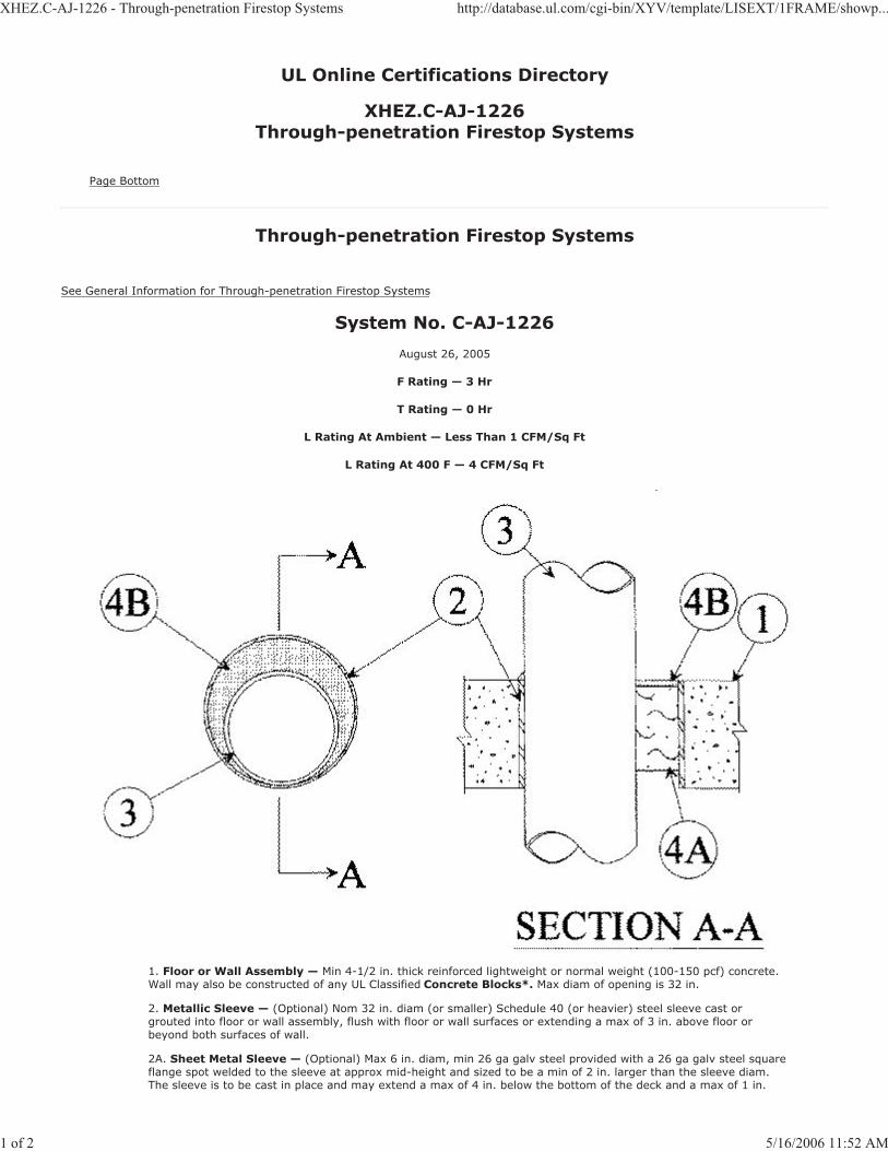
XHEZ.C-AJ-1226 - Through-penetration Firestop Systems http://database.ul.com/cgi-bin/XYV/template/LISEXT/1FRAME/showp...
1 of 2 5/16/2006 11:52 AM
UL Online Certifications Directory
XHEZ.C-AJ-1226Through-penetration Firestop Systems
Page Bottom
Through-penetration Firestop Systems
See General Information for Through-penetration Firestop Systems
System No. C-AJ-1226
August 26, 2005
F Rating — 3 Hr
T Rating — 0 Hr
L Rating At Ambient — Less Than 1 CFM/Sq Ft
L Rating At 400 F — 4 CFM/Sq Ft
1. Floor or Wall Assembly — Min 4-1/2 in. thick reinforced lightweight or normal weight (100-150 pcf) concrete.Wall may also be constructed of any UL Classified Concrete Blocks*. Max diam of opening is 32 in.
2. Metallic Sleeve — (Optional) Nom 32 in. diam (or smaller) Schedule 40 (or heavier) steel sleeve cast orgrouted into floor or wall assembly, flush with floor or wall surfaces or extending a max of 3 in. above floor or beyond both surfaces of wall.
2A. Sheet Metal Sleeve — (Optional) Max 6 in. diam, min 26 ga galv steel provided with a 26 ga galv steel squareflange spot welded to the sleeve at approx mid-height and sized to be a min of 2 in. larger than the sleeve diam. The sleeve is to be cast in place and may extend a max of 4 in. below the bottom of the deck and a max of 1 in.
XHEZ.C-AJ-1226 - Through-penetration Firestop Systems http://database.ul.com/cgi-bin/XYV/template/LISEXT/1FRAME/showp...
2 of 2 5/16/2006 11:52 AM
above the top surface of the concrete floor.
2B. Sheet Metal Sleeve — (Optional) - Max 12 in. diam, min 24 ga galv steel provided with a 24 ga galv steelsquare flange spot welded to the sleeve at approx mid-height and sized to be a min of 2 in. larger than the sleeve diam. The sleeve is to be cast in place and may extend a max of 4 in. below the bottom of the deck and a max of 1in. above the top surface of the concrete floor.
3. Through-Penetrant — One metallic pipe, tube or conduit to be installed either concentrically or eccentricallywithin the firestop system. The annular space between penetrant and periphery of opening shall be min 0 in. (pointcontact) to max 1-7/8 in. Penetrant may be installed with continuous point contact. Penetrant to be rigidlysupported on both sides of floor or wall assembly. The following types and sizes of metallic penetrants may beused:
A. Steel Pipe — Nom 30 in. diam (or smaller) Schedule 10 (or heavier) steel pipe.
B. Iron Pipe — Nom 30 in. diam (or smaller) cast or ductile iron pipe.
C. Copper Pipe — Nom 6 in. diam (or smaller) Regular (or heavier) copper pipe.
D. Copper Tubing — Nom 6 in. diam (or smaller) Type L (or heavier) copper tubing.
E. Conduit — Nom 6 in. diam (or smaller) steel conduit.
F. Conduit — Nom 4 in. diam (or smaller) steel electrical metallic tubing (EMT).
4. Firestop System — The firestop system shall consist of the following:
A. Packing Material — Min 4 in. thickness of min 4 pcf mineral wool batt insulation firmlypacked into opening as a permanent form. Packing material to be recessed from top surface of floor or sleeve or from both surfaces of wall or sleeve as required to accommodate the required thickness of fill material.
B. Fill, Void or Cavity Material* — Sealant — Min 1/4 in. thickness of fill materialapplied within the annulus, flush with top surface of floor or sleeve or with both surfaces of wall or sleeve. At the point or continuous contact locations between penetrant and concreteor sleeve, a min 1/4 in. diam bead of fill material shall be applied at the concrete or sleeve/ pipe penetrant interface on the top surface of floor and on both surfaces of wall.
HILTI CONSTRUCTION CHEMICALS, DIV OF
HILTI INC — FS-One Sealant
*Bearing the UL Classification Mark
Last Updated on 2005-08-26
Questions? Notice of Disclaimer Page Top
Copyright © 2006 Underwriters Laboratories Inc.®
The appearance of a company's name or product in this database does not in itself assure that products so identified have been manufactured under UL's Follow-Up Service. Only those products bearing the UL Mark should be considered to be Listed and covered underUL's Follow-Up Service. Always look for the Mark on the product.
UL permits the reproduction of the material contained in the Online Certification Directory subject to the following conditions: 1. The Guide Information, Designs and/or Listings (files) must be presented in their entirety and in a non-misleading manner, without any manipulationof the data (or drawings). 2. The statement "Reprinted from the Online Certifications Directory with permission from UnderwritersLaboratories Inc." must appear adjacent to the extracted material. In addition, the reprinted material must include a copyright notice in thefollowing format: "Copyright © 2006 Underwriters Laboratories Inc.®"

XHEZ.C-AJ-1291 - Through-penetration Firestop Systems http://database.ul.com/cgi-bin/XYV/template/LISEXT/1FRAME/showp...
1 of 2 5/16/2006 11:51 AM
UL Online Certifications Directory
XHEZ.C-AJ-1291Through-penetration Firestop Systems
Page Bottom
Through-penetration Firestop Systems
See General Information for Through-penetration Firestop Systems
System No. C-AJ-1291
December 04, 2001
F Rating — 2 Hr
T Rating — 0 Hr
1. Floor or Wall Assembly — Min 2-1/2 in. thick reinforced lightweight or normal weight (100-150 pcf) concrete.
Wall may also be constructed of any UL Classified Concrete Blocks*. Max diam of opening is 30-7/8 in.
See Concrete Blocks (CAZT) category in the Fire Resistance Directory for names of manufacturers.
2. Through-Penetrant — One metallic pipe or conduit to be installed either concentrically or eccentrically within
the firestop system. The annular space between pipe or conduit and periphery of opening shall be min 0 in. to max
7/8 in. Pipe or conduit to be rigidly supported on both sides of floor or wall assembly. The following types and sizes of metallic pipes or conduits may be used:
A. Steel Pipe — Nom 30 in. diam (or smaller) Schedule 10 (or heavier) steel pipe.

XHEZ.C-AJ-1291 - Through-penetration Firestop Systems http://database.ul.com/cgi-bin/XYV/template/LISEXT/1FRAME/showp...
2 of 2 5/16/2006 11:51 AM
B. Iron Pipe — Nom 30 in. diam (or smaller) cast or ductile iron pipe.
C. Copper Pipe — Nom 6 in. diam (or smaller) Regular (or heavier) copper pipe.
D. Copper Tubing — Nom 6 in. diam (or smaller) Type L (or heavier) copper tubing.
E. Conduit — Nom 6 in. diam (or smaller) steel conduit.
F. Conduit — Nom 4 in. diam (or smaller) steel electrical metallic tubing (EMT).
3. Fill, Void or Cavity Material* — Sealant — Min 1/2 in. thickness of fill material applied within the annulus,
flush with top surface of floor or with both surfaces of wall. At the point contact location between pipe and concrete,
a min 1/4 in. diam bead of fill material shall be applied at the concrete/pipe interface on the top surface of floor and
on both surfaces of wall.
HILTI CONSTRUCTION CHEMICALS, DIV OF
HILTI INC — FS — ONE Sealant
*Bearing the UL Classification Mark
Last Updated on 2001-12-04
Questions? Notice of Disclaimer Page Top
Copyright © 2006 Underwriters Laboratories Inc.®
The appearance of a company's name or product in this database does not in itself assure that products so identified have been
manufactured under UL's Follow-Up Service. Only those products bearing the UL Mark should be considered to be Listed and covered under
UL's Follow-Up Service. Always look for the Mark on the product.
UL permits the reproduction of the material contained in the Online Certification Directory subject to the following conditions: 1. The Guide
Information, Designs and/or Listings (files) must be presented in their entirety and in a non-misleading manner, without any manipulation
of the data (or drawings). 2. The statement "Reprinted from the Online Certifications Directory with permission from Underwriters
Laboratories Inc." must appear adjacent to the extracted material. In addition, the reprinted material must include a copyright notice in thefollowing format: "Copyright © 2006 Underwriters Laboratories Inc.®"

XHEZ.C-AJ-1421 - Through-penetration Firestop Systems http://database.ul.com/cgi-bin/XYV/template/LISEXT/1FRAME/showp...
1 of 2 5/16/2006 11:53 AM
UL Online Certifications Directory
XHEZ.C-AJ-1421Through-penetration Firestop Systems
Page Bottom
Through-penetration Firestop Systems
See General Information for Through-penetration Firestop Systems
System No. C-AJ-1421
April 26, 2004
F Rating — 2 and 3 Hr (See Item 4B)
T Rating — 0 Hr
1. Floor or Wall Assembly — Min 4-1/2 in. (114 mm) thick reinforced lightweight or normal weight (100-150 pcf
or 1600-2400 kg/m3) concrete. Wall may also be constructed of any UL Classified Concrete Blocks*. Max diam of opening is 6 in. (152 mm).
See Concrete Blocks (CAZT) category in the Fire Resistance Directory for names of manufacturers.
2. Metallic Sleeve — (Optional) Nom 6 in. (152 mm) diam (or smaller) Schedule 40 (or heavier) steel sleeve castor grouted into floor or wall assembly, flush with floor or wall surfaces.
3. Through-Penetrant — One metallic pipe or conduit to be installed either concentrically or eccentrically withinthe firestop system. The annular space between pipe, tube or conduit and periphery of opening shall be min 0 in.(0 mm) (point contact) to max 5-3/8 in. (137 mm). Pipe or conduit to be rigidly supported on both sides of floor orwall assembly. The following types and sizes of metallic pipes or conduits may be used:
A. Steel Pipe — Nom 4 in. (102 mm) diam (or smaller) Schedule 10 (or heavier) steelpipe.
B. Iron Pipe — Nom 4 in. (102 mm) diam (or smaller) cast or ductile iron pipe.
C. Copper Pipe — Nom 4 in. (102 mm) diam (or smaller) Regular (or heavier) copperpipe.
XHEZ.C-AJ-1421 - Through-penetration Firestop Systems http://database.ul.com/cgi-bin/XYV/template/LISEXT/1FRAME/showp...
2 of 2 5/16/2006 11:53 AM
D. Copper Tubing — Nom 4 in. (102 mm) diam (or smaller) Type L (or heavier) coppertubing.
E. Conduit — Nom 4 in. (102 mm) diam (or smaller) steel conduit.
F. Conduit — Nom 4 in. (102 mm) diam (or smaller) steel electrical metallic tubing (EMT).
4. Firestop System — The firestop system shall consist of the following:
A. Packing Material — Min 4 in. (102 mm) thickness of min 4 pcf (64 kg/m3) mineralwool batt insulation firmly packed into opening as a permanent form. Packing material to berecessed from top surface of floor or from both surfaces of wall as required to accommodate the required thickness of fill material.
B. Fill, Void or Cavity Material* - Sealant — Min 1/4 in. (6 mm) thickness of fill materialapplied within the annulus, flush with top surface of floor or with both surfaces of wall. For 3 Hr rated assemblies, a min 1/4 in. (6 mm) diam bead of fill material shall be applied at the concrete/pipe interface at the point contact location on the top surface of floor and on both surfaces of wall.
HILTI CONSTRUCTION CHEMICALS, DIV OF
HILTI INC — FS-ONE Sealant or CP604 Self-Leveling Firestop Sealant. CP604 shall beused in floor applications only.
When CP604 is used, F Rating is 2 Hr.
*Bearing the UL Classification Mark
Last Updated on 2004-04-26
Questions? Notice of Disclaimer Page Top
Copyright © 2006 Underwriters Laboratories Inc.®
The appearance of a company's name or product in this database does not in itself assure that products so identified have been manufactured under UL's Follow-Up Service. Only those products bearing the UL Mark should be considered to be Listed and covered underUL's Follow-Up Service. Always look for the Mark on the product.
UL permits the reproduction of the material contained in the Online Certification Directory subject to the following conditions: 1. The Guide Information, Designs and/or Listings (files) must be presented in their entirety and in a non-misleading manner, without any manipulationof the data (or drawings). 2. The statement "Reprinted from the Online Certifications Directory with permission from UnderwritersLaboratories Inc." must appear adjacent to the extracted material. In addition, the reprinted material must include a copyright notice in thefollowing format: "Copyright © 2006 Underwriters Laboratories Inc.®"
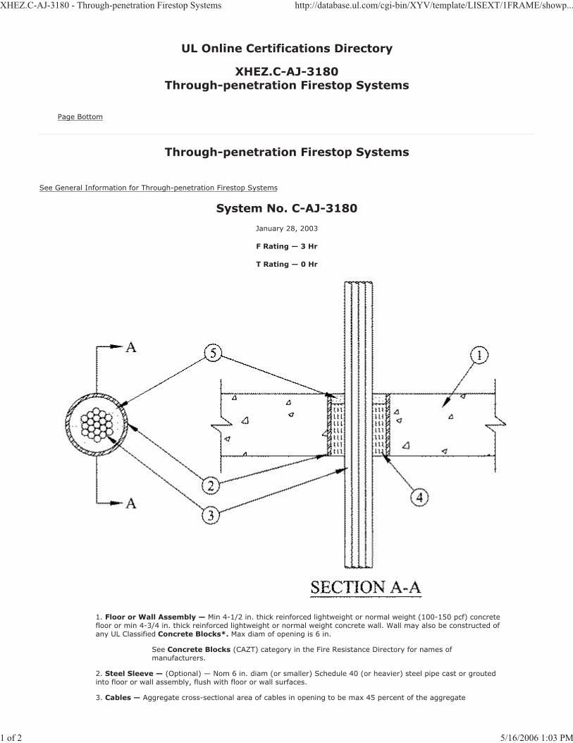
XHEZ.C-AJ-3180 - Through-penetration Firestop Systems http://database.ul.com/cgi-bin/XYV/template/LISEXT/1FRAME/showp...
1 of 2 5/16/2006 1:03 PM
UL Online Certifications Directory
XHEZ.C-AJ-3180Through-penetration Firestop Systems
Page Bottom
Through-penetration Firestop Systems
See General Information for Through-penetration Firestop Systems
System No. C-AJ-3180
January 28, 2003
F Rating — 3 Hr
T Rating — 0 Hr
1. Floor or Wall Assembly — Min 4-1/2 in. thick reinforced lightweight or normal weight (100-150 pcf) concretefloor or min 4-3/4 in. thick reinforced lightweight or normal weight concrete wall. Wall may also be constructed of any UL Classified Concrete Blocks*. Max diam of opening is 6 in.
See Concrete Blocks (CAZT) category in the Fire Resistance Directory for names of manufacturers.
2. Steel Sleeve — (Optional) — Nom 6 in. diam (or smaller) Schedule 40 (or heavier) steel pipe cast or groutedinto floor or wall assembly, flush with floor or wall surfaces.
3. Cables — Aggregate cross-sectional area of cables in opening to be max 45 percent of the aggregate

XHEZ.C-AJ-3180 - Through-penetration Firestop Systems http://database.ul.com/cgi-bin/XYV/template/LISEXT/1FRAME/showp...
2 of 2 5/16/2006 1:03 PM
cross-sectional area of the opening. Cables to be rigidly supported on both sides of floor or wall assembly. Any combination of the following types and sizes of metallic conductor or fiber optic cable may be used:
A. Max 500 kcmil single copper connector power cable with thermoplastic insulation andpolyvinyl chloride (PVC) jacket.
B. Max 300 pair No. 24 AWG copper conductor telecommunication cables with polyvinylchloride (PVC) insulation and jacket material.
C. Max 7/C copper conductor No. 12 AWG multiconductor power and control cables withpolyvinyl chloride (PVC) or cross-linked polyethylene (XLPE) insulation and PVC jacket.
D. Multiple fiber optical communication cables jacketed with PVC and having a max outsidediam of 1/2 in.
E. Max 3/C copper conductor No. 12 AWG with bare aluminum ground, polyvinyl chloride(PVC) insulated steel, Metal-clad cable.
F. Max 3/C with ground 2/0 AWG copper conductor SER cable with cross-linkedpolyethylene (XLPE) insulation and polyvinyl chloride (PVC) jacket.
G. RG/U coaxial cable with polyethylene (PE) insulation and polyvinyl chloride (PVC) jackethaving a max outside diameter of ½ in.
4. Packing Material — Min 4-1/4 in. thickness of min 4 pcf mineral wool batt insulation firmly packed into openingas a permanent form. Packing material to be recessed from top surface of floor to accommodate the required thickness of fill material.
5. Fill, Void or Cavity Material* — Sealant — Min 1/4 in. thickness of fill material applied within the annulus,flush with top surface of floor or with both surfaces of wall.
HILTI CONSTRUCTION CHEMICALS, DIV OF
HILTI INC — FS-One Sealant.
*Bearing the UL Classification Mark
Last Updated on 2003-01-28
Questions? Notice of Disclaimer Page Top
Copyright © 2006 Underwriters Laboratories Inc.®
The appearance of a company's name or product in this database does not in itself assure that products so identified have been manufactured under UL's Follow-Up Service. Only those products bearing the UL Mark should be considered to be Listed and covered underUL's Follow-Up Service. Always look for the Mark on the product.
UL permits the reproduction of the material contained in the Online Certification Directory subject to the following conditions: 1. The Guide Information, Designs and/or Listings (files) must be presented in their entirety and in a non-misleading manner, without any manipulationof the data (or drawings). 2. The statement "Reprinted from the Online Certifications Directory with permission from UnderwritersLaboratories Inc." must appear adjacent to the extracted material. In addition, the reprinted material must include a copyright notice in thefollowing format: "Copyright © 2006 Underwriters Laboratories Inc.®"
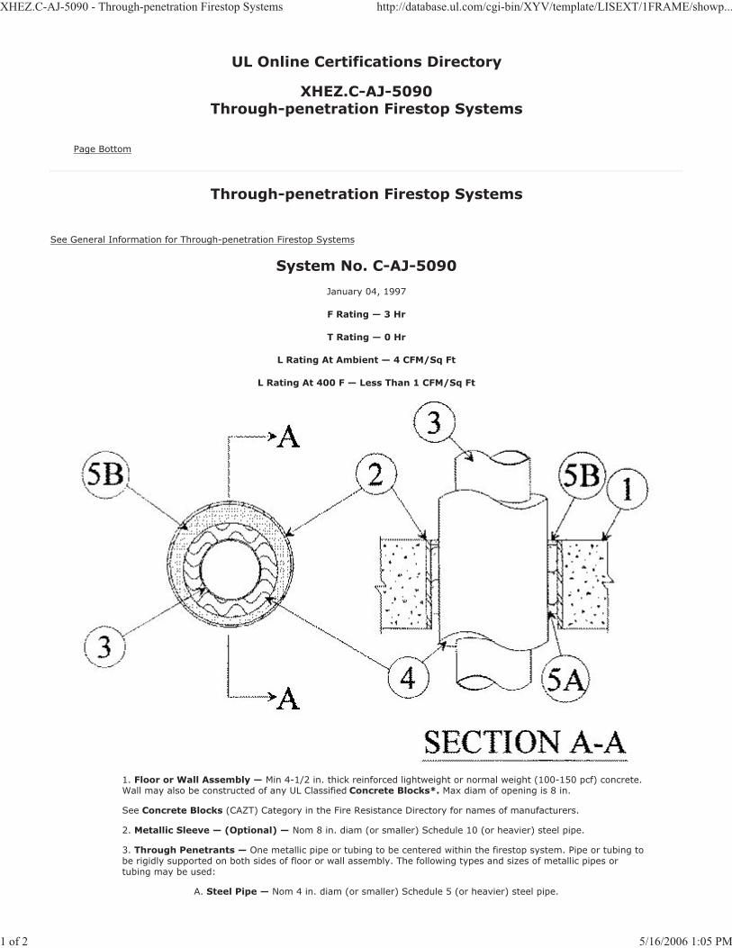
XHEZ.C-AJ-5090 - Through-penetration Firestop Systems http://database.ul.com/cgi-bin/XYV/template/LISEXT/1FRAME/showp...
1 of 2 5/16/2006 1:05 PM
UL Online Certifications Directory
XHEZ.C-AJ-5090Through-penetration Firestop Systems
Page Bottom
Through-penetration Firestop Systems
See General Information for Through-penetration Firestop Systems
System No. C-AJ-5090
January 04, 1997
F Rating — 3 Hr
T Rating — 0 Hr
L Rating At Ambient — 4 CFM/Sq Ft
L Rating At 400 F — Less Than 1 CFM/Sq Ft
1. Floor or Wall Assembly — Min 4-1/2 in. thick reinforced lightweight or normal weight (100-150 pcf) concrete.Wall may also be constructed of any UL Classified Concrete Blocks*. Max diam of opening is 8 in.
See Concrete Blocks (CAZT) Category in the Fire Resistance Directory for names of manufacturers.
2. Metallic Sleeve — (Optional) — Nom 8 in. diam (or smaller) Schedule 10 (or heavier) steel pipe.
3. Through Penetrants — One metallic pipe or tubing to be centered within the firestop system. Pipe or tubing tobe rigidly supported on both sides of floor or wall assembly. The following types and sizes of metallic pipes or tubing may be used:
A. Steel Pipe — Nom 4 in. diam (or smaller) Schedule 5 (or heavier) steel pipe.

XHEZ.C-AJ-5090 - Through-penetration Firestop Systems http://database.ul.com/cgi-bin/XYV/template/LISEXT/1FRAME/showp...
2 of 2 5/16/2006 1:05 PM
B. Copper Pipe — Nom 4 in. diam (or smaller) Regular (or heavier) copper tubing.
C. Copper Tubing — Nom 4 in. diam (or smaller) Type L (or heavier) copper tubing.
4. Tube Insulation — Plastics+ — Nom 3/4 in., thick acrylonitrile butadiene/polyvinyl chloride (AB/PVC) flexiblefoam furnished in the form of tubing. A annular space shall be min 1/2 in. to max of 1-1/2 in.
See Plastics+ (QMFZ2) Category in the Recognized Component Directory for names of manufacturers. AnyRecognized Component tube insulation material meeting the above specifications and having a UL 94 Flammability Classification of 94-5VA may be used.
5. Firestop System — The firestop system shall consist of the following:
A. Packing Material — Min 4 in. thickness of min 4 pcf mineral wool batt insulation firmlypacked into opening as a permanent form. Packing material to be recessed from top surface of floor or from both surfaces of wall as required to accommodate the required thickness of fill material.
B. Fill, Void or Cavity Material* — Sealant — Min 1/4 in. thickness of fill materialapplied within the annulus, flush with top surface of floor or with both surfaces of wall.
HILTI CONSTRUCTION CHEMICALS, DIV OF
HILTI INC — FS-One Sealant
*Bearing the UL Classification Mark
Last Updated on 1997-01-04
Questions? Notice of Disclaimer Page Top
Copyright © 2006 Underwriters Laboratories Inc.®
The appearance of a company's name or product in this database does not in itself assure that products so identified have been manufactured under UL's Follow-Up Service. Only those products bearing the UL Mark should be considered to be Listed and covered underUL's Follow-Up Service. Always look for the Mark on the product.
UL permits the reproduction of the material contained in the Online Certification Directory subject to the following conditions: 1. The Guide Information, Designs and/or Listings (files) must be presented in their entirety and in a non-misleading manner, without any manipulationof the data (or drawings). 2. The statement "Reprinted from the Online Certifications Directory with permission from UnderwritersLaboratories Inc." must appear adjacent to the extracted material. In addition, the reprinted material must include a copyright notice in thefollowing format: "Copyright © 2006 Underwriters Laboratories Inc.®"

XHEZ.C-AJ-5091 - Through-penetration Firestop Systems http://database.ul.com/cgi-bin/XYV/template/LISEXT/1FRAME/showp...
1 of 2 5/16/2006 1:04 PM
UL Online Certifications Directory
XHEZ.C-AJ-5091Through-penetration Firestop Systems
Page Bottom
Through-penetration Firestop Systems
See General Information for Through-penetration Firestop Systems
System No. C-AJ-5091
February 08, 2006
F Rating — 2 Hr
T Rating — 1 Hr
L Rating At Ambient — 4 CFM/Sq Ft
L Rating At 400 F — Less Than 1 CFM/Sq Ft
1. Floor or Wall Assembly — Min 4-1/2 in. thick reinforced lightweight or normal weight (100-150 pcf) concrete.Wall may also be constructed of any UL Classified Concrete Blocks*. Max diam of opening is 19-1/2 in.
See Concrete Blocks (CAZT) category in the Fire Resistance directory for names of manufacturers.
2. Metallic Sleeve — (Optional) — Nom 20 in. diam (or smaller) Schedule 10 (or heavier) steel pipe.
2A. Sheet Metal Sleeve — (Optional) - Max 6 in. diam, min 26 ga galv steel provided with a 26 ga galv steelsquare flange spot welded to the bottom of sleeve and sized to be a min of 2 in. larger than the sleeve diam. The sleeve is to be cast in place flush with bottom surface of floor and may extend a max of 1 in. above the top surface of the floor.
2B. Sheet Metal Sleeve — (Optional) - Max 12 in. diam, min 24 ga galv steel provided with a 24 ga galv steelsquare flange spot welded to the sleeve at bottom of sleeve and sized to be a min of 2 in. larger than the sleeve diam. The sleeve is to be cast in place flush with bottom surface of floor and may extend a max of 1 in. above the

XHEZ.C-AJ-5091 - Through-penetration Firestop Systems http://database.ul.com/cgi-bin/XYV/template/LISEXT/1FRAME/showp...
2 of 2 5/16/2006 1:04 PM
top surface of the floor.
3. Through Penetrants — One metallic pipe or tubing to be installed either concentrically or eccentrically withinthe firestop system. Pipe or tubing to be rigidly supported on both sides of floor or wall assembly. The following types and sizes of metallic pipes or tubing may be used:
A. Steel Pipe — Nom 12 in. diam (or smaller) Schedule 10 (or heavier) steel pipe.
B. Iron Pipe — Nom 12 in. diam (or smaller) cast or ductile iron pipe.
C. Copper Pipe — Nom 6 in. diam (or smaller) Regular (or heavier) copper pipe.
D. Copper Tubing — Nom 6 in. diam (or smaller) Type L (or heavier) copper tubing.
4. Pipe Covering — Nom 2 in. thick hollow cylindrical heavy density (min 3.5 pcf) glass fiber units jacketed on theoutside with an all-service jacket. Longitudinal joints sealed with metal fasteners or factory-applied, self-sealing lap tape. Transverse joints secured with metal fasteners or with butt tape supplied with the product. The annular spacebetween the insulated pipe and the edge of the periphery of the opening shall be min 1/2 in. to a max 2-1/4 in.
See Pipe Equipment Covering — Materials — (BRGU) category in the Building Materials Directory for names ofmanufacturers. Any pipe covering material meeting the above specifications and bearing the UL ClassificationMarking with a Flame Spread Index of 25 or less and a Smoke Developed Index of 50 or less may be used.
4A. Pipe Covering — (Not Shown) — As an alternate to Item 4, max 2 in. thick cylindrical calcium silicate (min 14pcf) units sized to the outside diam of the pipe or tube may be used. Pipe insulation secured with stainless steelbands or min 8 AWG stainless steel wire spaced max 12 in. OC. The annular space shall be min 1/2 in. to max2-1/4 in.
5. Firestop System — The firestop system shall consist of the following:
A. Packing Material — Min 4 in. thickness of min 4 pcf mineral wool batt insulation firmlypacked into opening as a permanent form. Packing material to be recessed from top surface of floor or from both surfaces of wall as required to accommodate the required thickness of fill material.
B. Fill, Void or Cavity Material* — Sealant — Min 1/2 in. thickness of fill materialapplied within the annulus, flush with top surface of floor or with both surfaces of wall.
HILTI CONSTRUCTION CHEMICALS, DIV OF
HILTI INC — FS-One Sealant
*Bearing the UL Classification Mark
Last Updated on 2006-02-08
Questions? Notice of Disclaimer Page Top
Copyright © 2006 Underwriters Laboratories Inc.®
The appearance of a company's name or product in this database does not in itself assure that products so identified have been manufactured under UL's Follow-Up Service. Only those products bearing the UL Mark should be considered to be Listed and covered underUL's Follow-Up Service. Always look for the Mark on the product.
UL permits the reproduction of the material contained in the Online Certification Directory subject to the following conditions: 1. The Guide Information, Designs and/or Listings (files) must be presented in their entirety and in a non-misleading manner, without any manipulationof the data (or drawings). 2. The statement "Reprinted from the Online Certifications Directory with permission from UnderwritersLaboratories Inc." must appear adjacent to the extracted material. In addition, the reprinted material must include a copyright notice in thefollowing format: "Copyright © 2006 Underwriters Laboratories Inc.®"
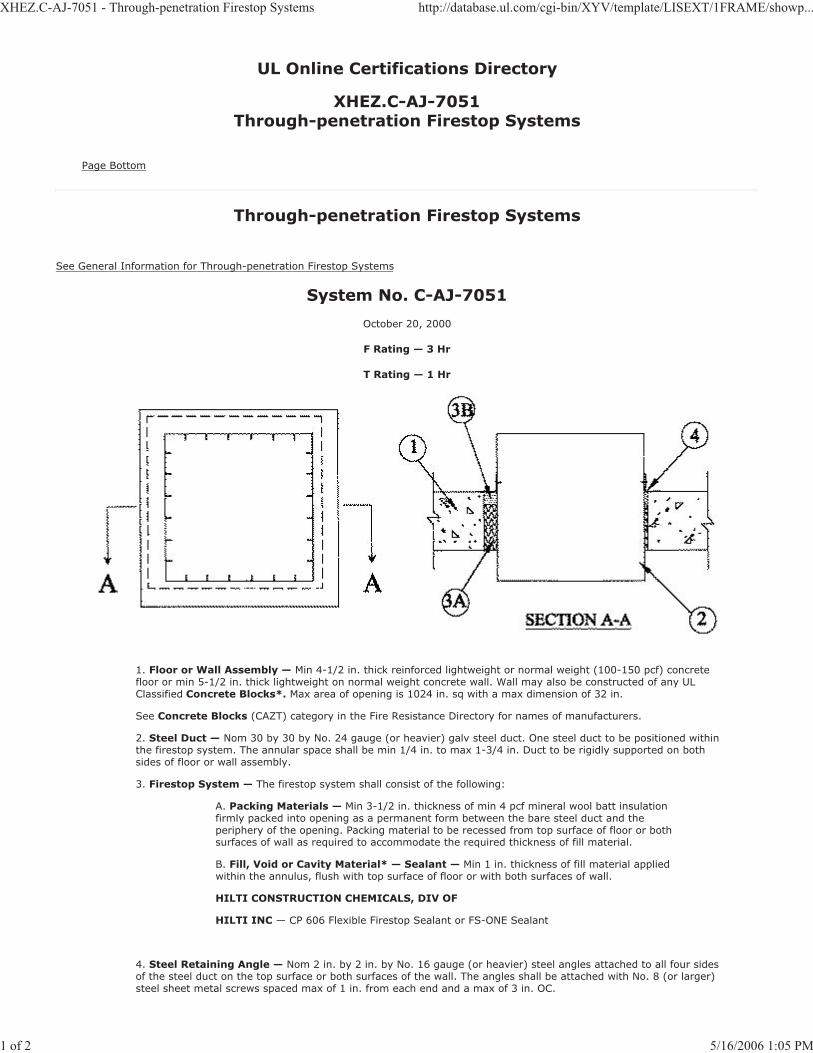
XHEZ.C-AJ-7051 - Through-penetration Firestop Systems http://database.ul.com/cgi-bin/XYV/template/LISEXT/1FRAME/showp...
1 of 2 5/16/2006 1:05 PM
UL Online Certifications Directory
XHEZ.C-AJ-7051Through-penetration Firestop Systems
Page Bottom
Through-penetration Firestop Systems
See General Information for Through-penetration Firestop Systems
System No. C-AJ-7051
October 20, 2000
F Rating — 3 Hr
T Rating — 1 Hr
1. Floor or Wall Assembly — Min 4-1/2 in. thick reinforced lightweight or normal weight (100-150 pcf) concretefloor or min 5-1/2 in. thick lightweight on normal weight concrete wall. Wall may also be constructed of any UL Classified Concrete Blocks*. Max area of opening is 1024 in. sq with a max dimension of 32 in.
See Concrete Blocks (CAZT) category in the Fire Resistance Directory for names of manufacturers.
2. Steel Duct — Nom 30 by 30 by No. 24 gauge (or heavier) galv steel duct. One steel duct to be positioned withinthe firestop system. The annular space shall be min 1/4 in. to max 1-3/4 in. Duct to be rigidly supported on both sides of floor or wall assembly.
3. Firestop System — The firestop system shall consist of the following:
A. Packing Materials — Min 3-1/2 in. thickness of min 4 pcf mineral wool batt insulationfirmly packed into opening as a permanent form between the bare steel duct and the periphery of the opening. Packing material to be recessed from top surface of floor or both surfaces of wall as required to accommodate the required thickness of fill material.
B. Fill, Void or Cavity Material* — Sealant — Min 1 in. thickness of fill material appliedwithin the annulus, flush with top surface of floor or with both surfaces of wall.
HILTI CONSTRUCTION CHEMICALS, DIV OF
HILTI INC — CP 606 Flexible Firestop Sealant or FS-ONE Sealant
4. Steel Retaining Angle — Nom 2 in. by 2 in. by No. 16 gauge (or heavier) steel angles attached to all four sidesof the steel duct on the top surface or both surfaces of the wall. The angles shall be attached with No. 8 (or larger) steel sheet metal screws spaced max of 1 in. from each end and a max of 3 in. OC.

XHEZ.C-AJ-7051 - Through-penetration Firestop Systems http://database.ul.com/cgi-bin/XYV/template/LISEXT/1FRAME/showp...
2 of 2 5/16/2006 1:05 PM
*Bearing the UL Classification Mark
Last Updated on 2000-10-20
Questions? Notice of Disclaimer Page Top
Copyright © 2006 Underwriters Laboratories Inc.®
The appearance of a company's name or product in this database does not in itself assure that products so identified have been manufactured under UL's Follow-Up Service. Only those products bearing the UL Mark should be considered to be Listed and covered underUL's Follow-Up Service. Always look for the Mark on the product.
UL permits the reproduction of the material contained in the Online Certification Directory subject to the following conditions: 1. The Guide Information, Designs and/or Listings (files) must be presented in their entirety and in a non-misleading manner, without any manipulationof the data (or drawings). 2. The statement "Reprinted from the Online Certifications Directory with permission from UnderwritersLaboratories Inc." must appear adjacent to the extracted material. In addition, the reprinted material must include a copyright notice in thefollowing format: "Copyright © 2006 Underwriters Laboratories Inc.®"
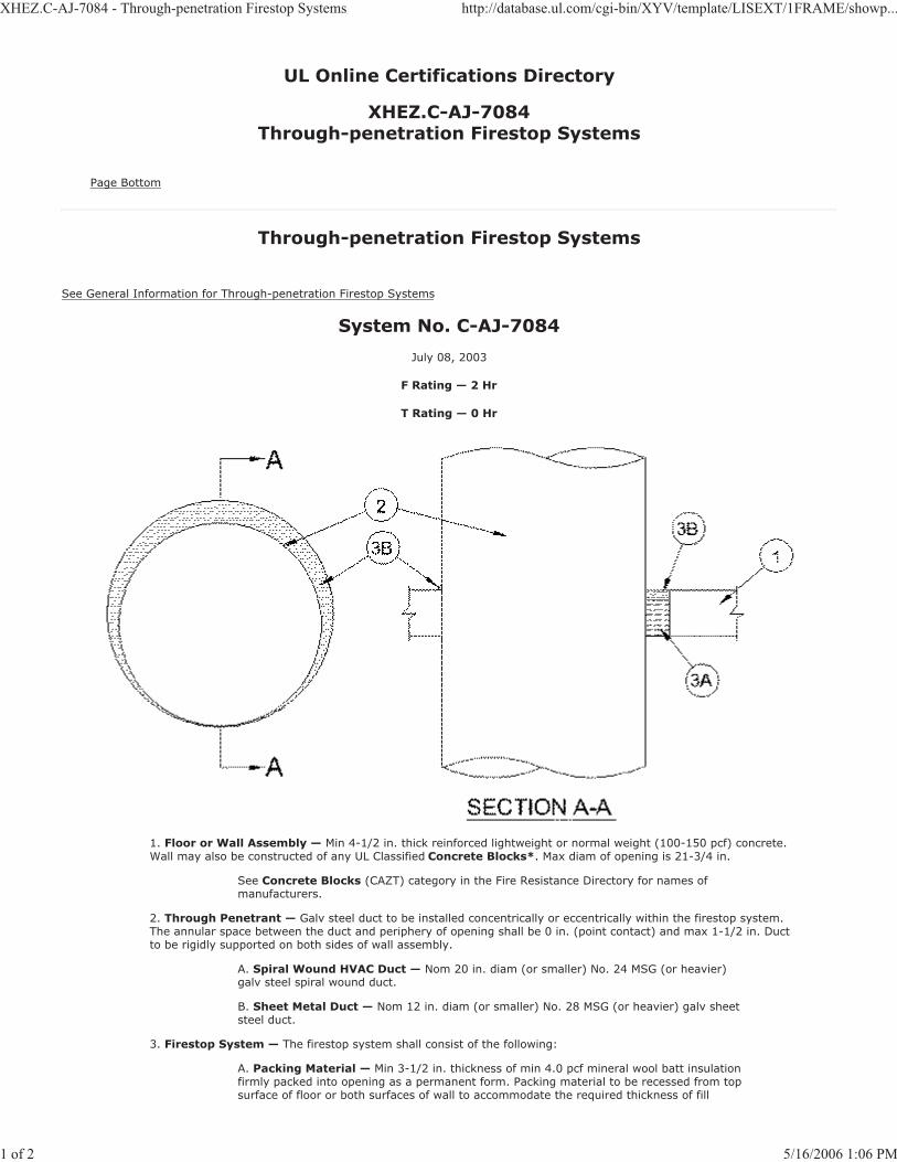
XHEZ.C-AJ-7084 - Through-penetration Firestop Systems http://database.ul.com/cgi-bin/XYV/template/LISEXT/1FRAME/showp...
1 of 2 5/16/2006 1:06 PM
UL Online Certifications Directory
XHEZ.C-AJ-7084Through-penetration Firestop Systems
Page Bottom
Through-penetration Firestop Systems
See General Information for Through-penetration Firestop Systems
System No. C-AJ-7084
July 08, 2003
F Rating — 2 Hr
T Rating — 0 Hr
1. Floor or Wall Assembly — Min 4-1/2 in. thick reinforced lightweight or normal weight (100-150 pcf) concrete.Wall may also be constructed of any UL Classified Concrete Blocks*. Max diam of opening is 21-3/4 in.
See Concrete Blocks (CAZT) category in the Fire Resistance Directory for names of manufacturers.
2. Through Penetrant — Galv steel duct to be installed concentrically or eccentrically within the firestop system.The annular space between the duct and periphery of opening shall be 0 in. (point contact) and max 1-1/2 in. Duct to be rigidly supported on both sides of wall assembly.
A. Spiral Wound HVAC Duct — Nom 20 in. diam (or smaller) No. 24 MSG (or heavier)galv steel spiral wound duct.
B. Sheet Metal Duct — Nom 12 in. diam (or smaller) No. 28 MSG (or heavier) galv sheetsteel duct.
3. Firestop System — The firestop system shall consist of the following:
A. Packing Material — Min 3-1/2 in. thickness of min 4.0 pcf mineral wool batt insulationfirmly packed into opening as a permanent form. Packing material to be recessed from topsurface of floor or both surfaces of wall to accommodate the required thickness of fill
XHEZ.C-AJ-7084 - Through-penetration Firestop Systems http://database.ul.com/cgi-bin/XYV/template/LISEXT/1FRAME/showp...
2 of 2 5/16/2006 1:06 PM
material.
B. Fill, Void or Cavity Material*—Sealant — Min 1 in. thickness of fill material appliedwithin annulus, flush with top surface of floor or both surfaces of wall assembly. At the point contact location between duct and periphery of opening, a min 1/2 in. diam bead of sealant shall be applied at the concrete/duct interface.
HILTI CONSTRUCTION CHEMICALS, DIV OF
HILTI INC — FS-ONE Sealant, CP601S Elastomeric Firestop Sealant, CP606 FlexibleFirestop Sealant or CP 604 Self-Leveling Firestop Sealant.
(Note: CP 604 Self-Leveling Firestop Sealant to be used on floor assemblies only.)
*Bearing the UL Classification Mark
Last Updated on 2003-07-08
Questions? Notice of Disclaimer Page Top
Copyright © 2006 Underwriters Laboratories Inc.®
The appearance of a company's name or product in this database does not in itself assure that products so identified have been manufactured under UL's Follow-Up Service. Only those products bearing the UL Mark should be considered to be Listed and covered underUL's Follow-Up Service. Always look for the Mark on the product.
UL permits the reproduction of the material contained in the Online Certification Directory subject to the following conditions: 1. The Guide Information, Designs and/or Listings (files) must be presented in their entirety and in a non-misleading manner, without any manipulationof the data (or drawings). 2. The statement "Reprinted from the Online Certifications Directory with permission from UnderwritersLaboratories Inc." must appear adjacent to the extracted material. In addition, the reprinted material must include a copyright notice in thefollowing format: "Copyright © 2006 Underwriters Laboratories Inc.®"
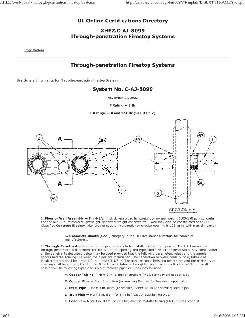
XHEZ.C-AJ-8099 - Through-penetration Firestop Systems http://database.ul.com/cgi-bin/XYV/template/LISEXT/1FRAME/showp...
1 of 3 5/16/2006 1:07 PM
UL Online Certifications Directory
XHEZ.C-AJ-8099Through-penetration Firestop Systems
Page Bottom
Through-penetration Firestop Systems
See General Information for Through-penetration Firestop Systems
System No. C-AJ-8099
November 11, 2002
F Rating — 3 Hr
T Ratings — 0 and 3/4 Hr (See Item 2)
1. Floor or Wall Assembly — Min 4-1/2 in. thick reinforced lightweight or normal weight (100-150 pcf) concretefloor or min 5 in. reinforced lightweight or normal weight concrete wall. Wall may also be constructed of any UL Classified Concrete Blocks*. Max area of square, rectangular or circular opening is 192 sq in. with max dimensionof 24 in.
See Concrete Blocks (CAZT) category in the Fire Resistance Directory for names of manufacturers.
2. Through-Penetrant — One or more pipes or tubes to be installed within the opening. The total number ofthrough-penetrants is dependent on the size of the opening and types and sizes of the penetrants. Any combinationof the penetrants described below may be used provided that the following parameters relative to the annular spaces and the spacings between the pipes are maintained. The seperation between cable bundle, tubes and insulated tubes shall be a min 1/2 in. to max 3-1/8 in. The annular space between penetrants and the periphery of opening shall be a min 1/2 in. to max 5 in. Pipes or tubes to be rigidly supported on both sides of floor or wall assembly. The following types and sizes of metallic pipes or tubes may be used.
A. Copper Tubing — Nom 3 in. diam (or smaller) Tyle L (or heavier) copper tube.
B. Copper Pipe — Nom 3 in. diam (or smaller) Regular (or heavier) copper pipe.
C. Steel Pipe — Nom 3 in. diam (or smaller) Schedule 10 (or heavier) steel pipe.
D. Iron Pipe — Nom 3 in. diam (or smaller) cast or ductile iron pipe.
E. Conduit — Nom 3 in. diam (or smaller) electric metallic tubing (EMT) or steel conduit.

XHEZ.C-AJ-8099 - Through-penetration Firestop Systems http://database.ul.com/cgi-bin/XYV/template/LISEXT/1FRAME/showp...
2 of 3 5/16/2006 1:07 PM
F. Flexible Steel Conduit + — Nom 1 in. diameter (or smaller) flexible steel conduit.
See Flexible Metal Conduit (DXUZ) category in the Electrical Construction MaterialDirectory for names of manufacturers.
The hourly T Rating is 3/4 hr when a pipe or tube with fiber-glass insulation isused, or 0 hr when a pipe or tube, a pipe or tube with AB/PVC insulation or acable bundle is used.
3. Pipe Insulation — (Optional)—The following types of pipe insulation may be used:
A. Pipe Covering* — Nom 1 in. thick (or thinener) hollow cylindrical heavy density (min3.5 pcf) glass fiber units jacketed on the outside with an all service jacket. Longitudinal joints sealed with metal fasteners or factory-applied self-sealing lap tape. Transverse joints secured with metal fasteners or with butt tape supplied with the product.
See Pipe and Equipment Covering - Materials (BRGU) category in the Building MaterialsDirectory for names of manufacturers. Any pipe covering material meeting the above specifications and bearing the UL Classifica tion Marking with a Flame Spread Index of 25 orless and a Smoke Developed Index of 50 or less may be used.
B. Tube Insulation-Plastics+++ — Nom 3/4 in. thick (or thinner) acrylonitrilebutadiene/polyvinyl chloride (AB/PVC) flexible foam furnished in the foarm of tubing.
See Plastics+++ (QMFZ2) category in the Plastics Recognized Component Directory for names of manufacturers. Any Recognized Component tube insulation material meeting the above specifications and having a UL 94 Flammability Classification of 94-5VA may be used.
4. Cables — Max 2 in. diam tight bundle of cables installed within the opening and rigidly supported on both sidesof floor or wall assembly. The space between the cables and periphery of the opening shall range from min 2 in. to max 4 in. Any combination of the following types and sizes of metallic conductor of fiber optic cable may be used:
A. Max 500 kcmil single copper connector power cable with thermoplastic insulation andpolyvinyl chloride (PVC) jacket.
B. Max 300 pair No. 24 AWG copper conductor telecommunication cables with PVCinsulation and jacket material.
C. Max 7/C copper conductor No. 12 AWG multiconductor power and control cables withPVC or cross-linked polyethylene (XLPE) insulation and PVC jacket.
D. Multiple fiber optical communication cables jacketed with PVC and having a max outsidediam of 1/2 in.
E. Max 3/C copper conductor No. 12 AWG with bare aluminum ground, PVC insulated steelMetal-Clad cable.
5. Firestop System — The firestop system shall consist of the following:
A. Packing Material — Min 4 in. thickness of min 4 pcf mineral wool batt insulation firmlypacked into opening as a permanent form. Packing material to be recessed from top surface of floor or both surfaces of wall to accommodate the required thickenss of fill material.
B. Fill Void or Cavity Materials* - Sealant — Min 1/2 in. thickness of fill material appliedwithin the annulus, flush with top surface of floor or with both surfaces of wall.
HILTI CONSTRUCTION CHEMICALS, DIV OF
HILTI INC — FS-ONE Sealant
+++Bearing the UL Recognized Component Marking
*Bearing the UL Classification Mark
+Bearing the UL Listing Mark
Last Updated on 2002-11-11
Questions? Notice of Disclaimer Page Top
Copyright © 2006 Underwriters Laboratories Inc.®
The appearance of a company's name or product in this database does not in itself assure that products so identified have been manufactured under UL's Follow-Up Service. Only those products bearing the UL Mark should be considered to be Listed and covered underUL's Follow-Up Service. Always look for the Mark on the product.
UL permits the reproduction of the material contained in the Online Certification Directory subject to the following conditions: 1. The Guide

XHEZ.C-AJ-8099 - Through-penetration Firestop Systems http://database.ul.com/cgi-bin/XYV/template/LISEXT/1FRAME/showp...
3 of 3 5/16/2006 1:07 PM
Information, Designs and/or Listings (files) must be presented in their entirety and in a non-misleading manner, without any manipulationof the data (or drawings). 2. The statement "Reprinted from the Online Certifications Directory with permission from UnderwritersLaboratories Inc." must appear adjacent to the extracted material. In addition, the reprinted material must include a copyright notice in thefollowing format: "Copyright © 2006 Underwriters Laboratories Inc.®"

XHEZ.C-AJ-8143 - Through-penetration Firestop Systems http://database.ul.com/cgi-bin/XYV/template/LISEXT/1FRAME/showp...
1 of 3 5/16/2006 1:07 PM
UL Online Certifications Directory
XHEZ.C-AJ-8143Through-penetration Firestop Systems
Page Bottom
Through-penetration Firestop Systems
See General Information for Through-penetration Firestop Systems
System No. C-AJ-8143
April 26, 2004
F Rating — 2 Hr
T Rating — 0 Hr
1. Floor or Wall Assembly — Min 4-1/2 in. (114 mm) thick reinforced lightweight or normal weight (100-150 pcf
or 1600-2400 kg/m3) concrete floor. Min 5 in. (127 mm) thick reinforced lightweight or normal weight (100-150
pcf or 1600-2400 kg/m3) concrete wall. Wall may also be constructed of any UL Classified Concrete Blocks*. Max
size of opening is 1440 in.2 (9,290 cm2) with a max dimension of 48 in. (1219 mm).
See Concrete Blocks (CAZT) category in the Fire Resistance Directory for names ofmanufacturers.
2. Through-Penetrant — One or more pipes, tubes or cable bundles to be installed within the opening. The total
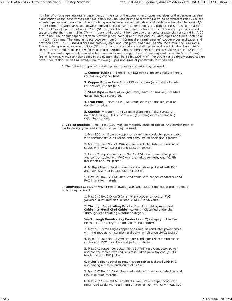
XHEZ.C-AJ-8143 - Through-penetration Firestop Systems http://database.ul.com/cgi-bin/XYV/template/LISEXT/1FRAME/showp...
2 of 3 5/16/2006 1:07 PM
number of through-penetrants is dependent on the size of the opening and types and sizes of the penetrants. Any combination of the penetrants described below may be used provided that the following parameters relative to the annular spaces are maintained. The annular space between individual cables and cable bundles shall be a min 1/2 in. (13 mm). The annular space between individual cables and cable bundles and other penetrants shall be a min 1/2 in. (13 mm) except that a min 2 in. (51 mm) shall be maintained between the cables and copper pipes and tubes greater than a nom 3 in. (76 mm) diam and steel and iron pipes and conduits greater than a nom 4 in. (102 mm) diam. The annular space between metallic pipes, conduit and tubes and insulated pipes and tubes shall be a min 2 in. (51 mm). The annular space between nom 3 in (76mm) diam (and smaller) copper pipes and tubes and between nom 4 in (102mm) diam (and smaller) steel and iron pipes and conduits shall be a min. 1/2" (13 mm). The annular space between nom 2 in. (51 mm) diam (and smaller) metallic pipes and conduits shall be a min 0 in. (0 mm). The annular space between insulated penetrants and the periphery of opening shall be a min 1/2 in. (13 mm). The annular space between all other penetrants and the periphery of opening shall be a min 0 in. (0 mm) (point contact). A max annular space in the system shall be 12 in. (305 mm). Penetrants to be rigidly supported onboth sides of floor or wall assembly. The following types and sizes of penetrants may be used.
A. The following types of metallic pipes, tubes or conduits may be used:
1. Copper Tubing — Nom 6 in. (152 mm) diam (or smaller) Type L(or heavier) copper tube.
2. Copper Pipe — Nom 6 in. (152 mm) diam (or smaller) Regular(or heavier) copper pipe.
3. Steel Pipe — Nom 24 in. (610 mm) diam (or smaller) Schedule40 (or heavier) steel pipe.
4. Iron Pipe — Nom 24 in. (610 mm) diam (or smaller) cast orductile iron pipe.
5. Conduit — Nom 4 in. (102 mm) diam (or smaller) electricmetallic tubing (EMT) or nom 6 in. (152 mm) diam (or smaller)rigid steel conduit.
B. Cables Bundles — Max 4 in. (102 mm) diam tightly bundled cables. Any combination ofthe following types and sizes of cables may be used:
1. Max 500 kcmil single copper or aluminum conductor power cablewith thermoplastic insulation and polyvinyl chloride (PVC) jacket.
2. Max 300 pair No. 24 AWG copper conductor telecommunicationcables with PVC insulation and jacket material.
3. Max 7/C copper conductor No. 12 AWG multi-conductor powerand control cables with PVC or cross-linked polyethylene (XLPE) insulation and PVC jacket.
4. Multiple fiber optical communication cables jacketed with PVCand having a max outside diam of 1/2 in.
5. Max 3/C No. 12 AWG steel clad cable with copper conductors andPVC insulation material.
C. Individual Cables — Any of the following types and sizes of individual (non-bundled)cables may be used:
1. Max 3/C No. 2/0 AWG (or smaller) copper conductor PVCjacketed aluminum clad or steel clad TECK 90 cable.
2. Through Penetrating Product* — Any cables, ArmoredCable+ or Metal Clad Cable+ currently Classified under theThrough Penetrating Product category.
See Through Penetrating Product (XHLY) category in the FireResistance Directory for names of manufacturers.
3. Max 500 kcmil single copper or aluminum conductor power cablewith thermoplastic insulation and polyvinyl chloride (PVC) jacket.
4. Max 300 pair No. 24 AWG copper conductor telecommunicationcables with PVC insulation and jacket material.
5. Max 7/C copper conductor No. 12 AWG multi-conductor powerand control cables with PVC or cross-linked polyethylene (XLPE) insulation and PVC jacket.
6. Multiple fiber optical communication cables jacketed with PVCand having a max outside diam of 1/2 in.
7. Max 3/C No. 12 AWG steel clad cable with copper conductors andPVC insulation material.
8. Max 4C/750 kcmil (or smaller) aluminum or copper conductormetal clad cable with aluminum or steel armor, with or without PVC

XHEZ.C-AJ-8143 - Through-penetration Firestop Systems http://database.ul.com/cgi-bin/XYV/template/LISEXT/1FRAME/showp...
3 of 3 5/16/2006 1:07 PM
jacket.
3. Pipe Insulation — (Optional) - Pipes and tubes of the sizes noted below may be provided with one of thefollowing types of pipe insulations::
A. Pipe Covering* — Nom 1-1/2 in. (38 mm) thick (or thinner) hollow cylindrical heavydensity glass fiber units jacketed on the outside with an all service jacket for pipes with a nom diam of 8 in. (203 mm) (or smaller) or tubes with a nom diam of 4 in. (102 mm) (or smaller). Longitudinal joints sealed with metal fasteners or factory-applied self-sealing lap tape. Transverse joints secured with metal fasteners or with butt tape supplied with the product.
See Pipe and Equipment Covering - Materials (BRGU) category in the Building MaterialsDirectory for names of manufacturers. Any pipe covering material meeting the above specifications and bearing the UL Classification Marking with a Flame Spread Index of 25 or less and a Smoke Developed Index of 50 or less may be used.
B. Pipe Covering* — Nom 2 in. (51 mm) thick (or thinner) hollow cylindrical heavydensity glass fiber units jacketed on the outside with an all service jacket for pipes or tubes with a nom diam of 2 in. (51 mm) (or smaller). Longitudinal joints sealed with metal fasteners or factory-applied self-sealing lap tape. Transverse joints secured with metal fasteners or with butt tape supplied with the product.
See Pipe and Equipment Covering - Materials (BRGU) category in the Building MaterialsDirectory for names of manufacturers. Any pipe covering material meeting the above specifications and bearing the UL Classification Marking with a Flame Spread Index of 25 or less and a Smoke Developed Index of 50 or less may be used.
C. Tube Insulation-Plastics+ — Nom 1 in. (25 mm) thick (or thinner) acrylonitrilebutadiene/polyvinyl chloride (AB/PVC) flexible foam furnished in the form of tubing for pipes or tubes with a nom diam of 2 in. (51 mm) (or smaller).
See Plastics (QMFZ2) category in the Plastics Recognized Component Directory for names of manufacturers. Any Recognized Component tube insulation material meeting the above specifications and having a UL 94 Flammability Classification of 94-5VA may be used.
4. Firestop System — The firestop system shall consist of the following:
A. Packing Material — Min 4 in. (102 mm) thickness of 4 pcf (64 kg/m3) mineral woolbatt insulation tightly packed into the opening as a permanent form. Packing material to be recessed from top surface of floor or both surfaces of wall to accommodate the required thickness of fill material.
B. Fill, Void or Cavity Material - Sealant* — Min 1/2 in. (13 mm) thickness of fillmaterial applied within the annulus flush with the top surface of the floor or both surfaces of the wall.
HILTI CONSTRUCTION CHEMICALS, DIV OF
HILTI INC — FS-ONE Sealant
*Bearing the UL Classification Mark
Last Updated on 2004-04-26
Questions? Notice of Disclaimer Page Top
Copyright © 2006 Underwriters Laboratories Inc.®
The appearance of a company's name or product in this database does not in itself assure that products so identified have been manufactured under UL's Follow-Up Service. Only those products bearing the UL Mark should be considered to be Listed and covered underUL's Follow-Up Service. Always look for the Mark on the product.
UL permits the reproduction of the material contained in the Online Certification Directory subject to the following conditions: 1. The Guide Information, Designs and/or Listings (files) must be presented in their entirety and in a non-misleading manner, without any manipulationof the data (or drawings). 2. The statement "Reprinted from the Online Certifications Directory with permission from UnderwritersLaboratories Inc." must appear adjacent to the extracted material. In addition, the reprinted material must include a copyright notice in thefollowing format: "Copyright © 2006 Underwriters Laboratories Inc.®"
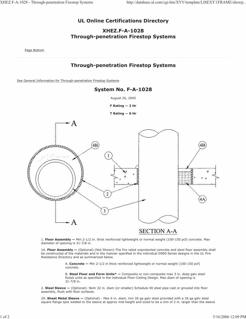
XHEZ.F-A-1028 - Through-penetration Firestop Systems http://database.ul.com/cgi-bin/XYV/template/LISEXT/1FRAME/showp...
1 of 2 5/16/2006 12:09 PM
UL Online Certifications Directory
XHEZ.F-A-1028Through-penetration Firestop Systems
Page Bottom
Through-penetration Firestop Systems
See General Information for Through-penetration Firestop Systems
System No. F-A-1028
August 26, 2005
F Rating — 2 Hr
T Rating — 0 Hr
1. Floor Assembly — Min 2-1/2 in. thick reinforced lightweight or normal weight (100-150 pcf) concrete. Maxdiameter of opening is 31-7/8 in.
1A. Floor Assembly — (Optional)-(Not Shown)-The fire rated unprotected concrete and steel floor assembly shallbe constructed of the materials and in the manner specified in the individual D900 Series designs in the UL Fire Resistance Directory and as summarized below.
A. Concrete — Min 2-1/2 in thick reinforced lightweight or normal weight (100-150 pcf)concrete.
B. Steel Floor and Form Units* — Composite or non-composite max 3 in. deep galv steelfluted units as specified in the individual Floor-Ceiling Design. Max diam of opening is 31-7/8 in.
2. Steel Sleeve — (Optional)- Nom 32 in. diam (or smaller) Schedule 40 steel pipe cast or grouted into floorassembly, flush with floor surfaces.
2A. Sheet Metal Sleeve — (Optional) - Max 6 in. diam, min 26 ga galv steel provided with a 26 ga galv steelsquare flange spot welded to the sleeve at approx mid-height and sized to be a min of 2 in. larger than the sleeve

XHEZ.F-A-1028 - Through-penetration Firestop Systems http://database.ul.com/cgi-bin/XYV/template/LISEXT/1FRAME/showp...
2 of 2 5/16/2006 12:09 PM
diam. The sleeve is to be cast in place and may extend a max of 4 in. below the bottom of the deck and a max of 1in. above the top surface of the concrete floor.
2B. Sheet Metal Sleeve — (Optional) - Max 12 in. diam, min 24 ga galv steel provided with a 24 ga galv steelsquare flange spot welded to the sleeve at approx mid-height and sized to be a min of 2 in. larger than the sleeve diam. The sleeve is to be cast in place may extend a max of 4 in. below the bottom of the deck and a max of 1 in. above the top surface of the concrete floor.
3. Through Penetrants — One metallic pipe, conduit or tubing to be installed concentrically within the firestopdevice. Pipe, conduit or tubing to be rigidly supported on both sides of floor assembly. The annular space between pipe conduit or tubing and the periphery of the opening shall be min 0 in. (point contact) to max 1-7/8 in. Thefollowing types of pipe, conduit or tubing may be used.
Steel Pipe — Nom 30 in. diam (or smaller) Schedule 10 (or heavier) steel pipe.
Iron Pipe — Nom 30 in. diam (or smaller) cast or ductile iron pipe.
Conduit — Nom 6 in. diam (or smaller) rigid steel conduit.
Conduit — Nom 4 in. diam (or smaller) steel electrical metallic conduit.
Copper Tubing — Nom 6 in. diam (or smaller) Type L (or heavier) copper tubing.
Copper Pipe — Nom 6 in. diam (or smaller) Regular (or heavier) copper pipe.
4. Firestop System — The firestop system shall consist of the following:
A. Packing Material — Min 2 in thickness of min 4 pcf mineral wool batt insulation tightlypacked into the opening as a permanent form. Packing material to be recessed from top surface of floor as required to accommodate the required thickness of fill material.
B. Fill, Void or Cavity Materials* - Sealant — Min 1/2 in. thickness of fill materialapplied within the annulus, flush with top surface of floor. At point contact, a min 1/2 in. diam bead of fill material shall be applied at the concrete/sleeve/pipe interface on top surface of floor.
HILTI CONSTRUCTION CHEMICALS, DIV OF
HILTI INC — FS-ONE Sealant
*Bearing the UL Classification Mark
Last Updated on 2005-08-26
Questions? Notice of Disclaimer Page Top
Copyright © 2006 Underwriters Laboratories Inc.®
The appearance of a company's name or product in this database does not in itself assure that products so identified have been manufactured under UL's Follow-Up Service. Only those products bearing the UL Mark should be considered to be Listed and covered underUL's Follow-Up Service. Always look for the Mark on the product.
UL permits the reproduction of the material contained in the Online Certification Directory subject to the following conditions: 1. The Guide Information, Designs and/or Listings (files) must be presented in their entirety and in a non-misleading manner, without any manipulationof the data (or drawings). 2. The statement "Reprinted from the Online Certifications Directory with permission from UnderwritersLaboratories Inc." must appear adjacent to the extracted material. In addition, the reprinted material must include a copyright notice in thefollowing format: "Copyright © 2006 Underwriters Laboratories Inc.®"
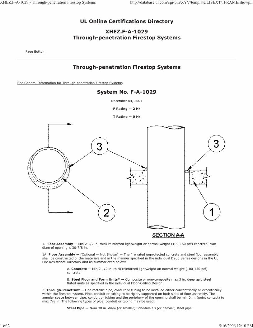
XHEZ.F-A-1029 - Through-penetration Firestop Systems http://database.ul.com/cgi-bin/XYV/template/LISEXT/1FRAME/showp...
1 of 2 5/16/2006 12:10 PM
UL Online Certifications Directory
XHEZ.F-A-1029Through-penetration Firestop Systems
Page Bottom
Through-penetration Firestop Systems
See General Information for Through-penetration Firestop Systems
System No. F-A-1029
December 04, 2001
F Rating — 2 Hr
T Rating — 0 Hr
1. Floor Assembly — Min 2-1/2 in. thick reinforced lightweight or normal weight (100-150 pcf) concrete. Maxdiam of opening is 30-7/8 in.
1A. Floor Assembly — (Optional — Not Shown) — The fire rated unprotected concrete and steel floor assemblyshall be constructed of the materials and in the manner specified in the individual D900 Series designs in the ULFire Resistance Directory and as summariezed below:
A. Concrete — Min 2-1/2 in. thick reinforced lightweight on normal weight (100-150 pcf)concrete.
B. Steel Floor and Form Units* — Composite or non-composite max 3 in. deep galv steelfluted units as specified in the individual Floor-Ceiling Design.
2. Through-Penetrant — One metallic pipe, conduit or tubing to be installed either concentrically or eccentricallywithin the firestop system. Pipe, conduit or tubing to be rigidly supported on both sides of floor assembly. The annular space between pipe, conduit or tubing and the periphery of the opening shall be min 0 in. (point contact) tomax 7/8 in. The following types of pipe, conduit or tubing may be used:
Steel Pipe — Nom 30 in. diam (or smaller) Schedule 10 (or heavier) steel pipe.

XHEZ.F-A-1029 - Through-penetration Firestop Systems http://database.ul.com/cgi-bin/XYV/template/LISEXT/1FRAME/showp...
2 of 2 5/16/2006 12:10 PM
Iron Pipe — Nom 30 in. diam (or smaller) cast or ductile iron pipe.
Conduit — Nom 6 in. diam (or smaller) rigid steel conduit.
Conduit — Nom 4 in. diam (or smaller) steel electrical metallic tubing (EMT).
Copper Tubing — Nom 6 in. diam (or smaller) Type L (or heavier) copper tubing.
Copper Pipe — Nom 6 in. diam (or smaller) Regular (or heavier) copper pipe.
3. Fill, Void or Cavity Material* — Sealant — Min 1/2 in. thickness of fill material applied within the annulus,flush with top surface of floor. At point contact, a min 1/4 in. diam bead of fill material shall be applied at the concrete/pipe interface on the top surface of floor.
HILTI CONSTRUCTION CHEMICALS, DIV OF
HILTI INC — FS-ONE Sealant
*Bearing the UL Classification Mark
Last Updated on 2001-12-04
Questions? Notice of Disclaimer Page Top
Copyright © 2006 Underwriters Laboratories Inc.®
The appearance of a company's name or product in this database does not in itself assure that products so identified have been manufactured under UL's Follow-Up Service. Only those products bearing the UL Mark should be considered to be Listed and covered underUL's Follow-Up Service. Always look for the Mark on the product.
UL permits the reproduction of the material contained in the Online Certification Directory subject to the following conditions: 1. The Guide Information, Designs and/or Listings (files) must be presented in their entirety and in a non-misleading manner, without any manipulationof the data (or drawings). 2. The statement "Reprinted from the Online Certifications Directory with permission from UnderwritersLaboratories Inc." must appear adjacent to the extracted material. In addition, the reprinted material must include a copyright notice in thefollowing format: "Copyright © 2006 Underwriters Laboratories Inc.®"
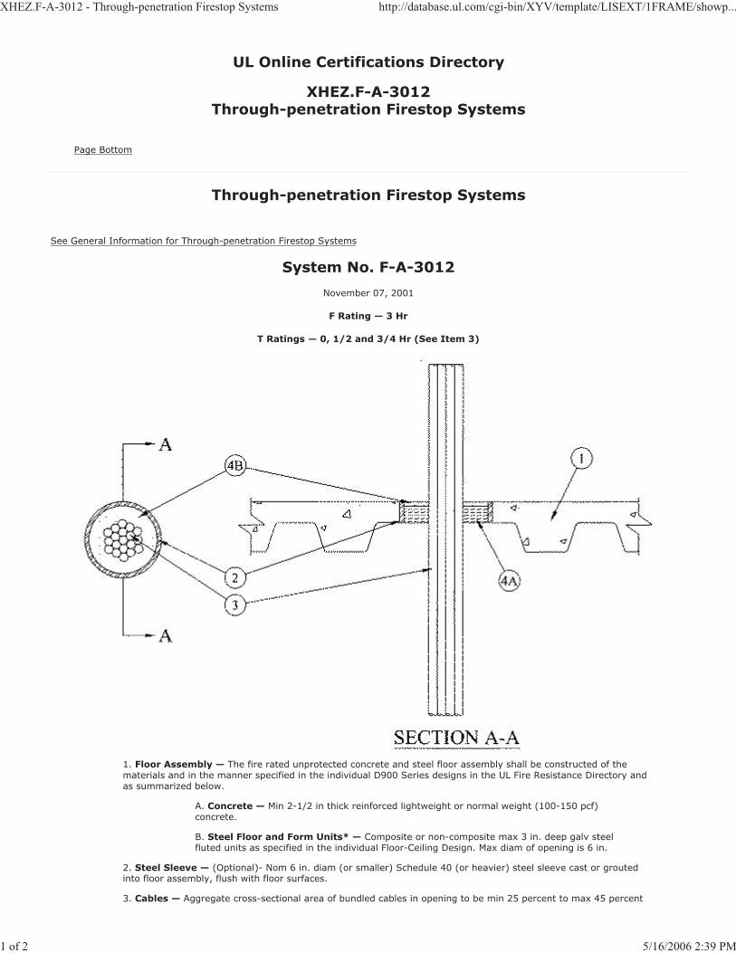
XHEZ.F-A-3012 - Through-penetration Firestop Systems http://database.ul.com/cgi-bin/XYV/template/LISEXT/1FRAME/showp...
1 of 2 5/16/2006 2:39 PM
UL Online Certifications Directory
XHEZ.F-A-3012Through-penetration Firestop Systems
Page Bottom
Through-penetration Firestop Systems
See General Information for Through-penetration Firestop Systems
System No. F-A-3012
November 07, 2001
F Rating — 3 Hr
T Ratings — 0, 1/2 and 3/4 Hr (See Item 3)
1. Floor Assembly — The fire rated unprotected concrete and steel floor assembly shall be constructed of thematerials and in the manner specified in the individual D900 Series designs in the UL Fire Resistance Directory and as summarized below.
A. Concrete — Min 2-1/2 in thick reinforced lightweight or normal weight (100-150 pcf)concrete.
B. Steel Floor and Form Units* — Composite or non-composite max 3 in. deep galv steelfluted units as specified in the individual Floor-Ceiling Design. Max diam of opening is 6 in.
2. Steel Sleeve — (Optional)- Nom 6 in. diam (or smaller) Schedule 40 (or heavier) steel sleeve cast or groutedinto floor assembly, flush with floor surfaces.
3. Cables — Aggregate cross-sectional area of bundled cables in opening to be min 25 percent to max 45 percent
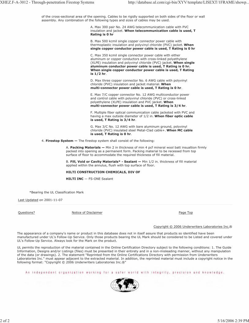
XHEZ.F-A-3012 - Through-penetration Firestop Systems http://database.ul.com/cgi-bin/XYV/template/LISEXT/1FRAME/showp...
2 of 2 5/16/2006 2:39 PM
of the cross-sectional area of the opening. Cables to be rigidly supported on both sides of the floor or wall assembly. Any combination of the following types and sizes of cables may be used.
A. Max 300 pair No. 24 AWG telecommunication cable with PVCinsulation and jacket. When telecommunication cable is used, TRating is 0 hr
B. Max 500 kcmil single copper connector power cable withthermoplastic insulation and polyvinyl chloride (PVC) jacket. Whensingle copper conductor power cable is used, T Rating is 0 hr
C. Max 350 kcmil single connector power cable with eitheraluminum or copper conductors with cross-linked polyethylene (XLPE) insulation and polyvinyl chloride (PVC) jacket. When singlealuminum conductor power cable is used, T Rating is 0 hr. When single copper conductor power cable is used, T Rating is 1/2 hr.
D. Max three copper connector No. 6 AWG cable with polyvinylchloride (PVC) insulation and jacket material. Whenmulti-connector power cable is used, T Rating is 0 hr.
E. Max 7/C copper connector No. 12 AWG multiconductor powerand control cable with polyvinyl chloride (PVC) or cross-linked polyethylene (XLPE) insulation and PVC jacket. Whenmulti-connector power cable is used, T Rating is 3/4 hr.
F. Multiple fiber optical communication cable jacketed with PVC andhaving a max outside diameter of 1/2 in. When fiber optic cable is used, T Rating is 3/4 hr.
G. Max 3/C No. 12 AWG with bare aluminum ground, polyvinylchloride (PVC) insulated steel Metal-Clad cable+. When MC cable is used, T Rating is 0 hr.
4. Firestop System — The firestop system shall consist of the following:
A. Packing Materials — Min 2 in thickness of min 4 pcf mineral wool batt insualtion firmlypacked into opening as a permanent form. Packing material to be recessed from top surface of floor to accommodate the required thickness of fill material.
B. Fill, Void or Cavity Materials* - Sealant — Min 1/2 in. thickness of fill materialapplied within the annulus, flush with top surface of floor.
HILTI CONSTRUCTION CHEMICALS, DIV OF
HILTI INC — FS-ONE Sealant
*Bearing the UL Classification Mark
Last Updated on 2001-11-07
Questions? Notice of Disclaimer Page Top
Copyright © 2006 Underwriters Laboratories Inc.®
The appearance of a company's name or product in this database does not in itself assure that products so identified have been manufactured under UL's Follow-Up Service. Only those products bearing the UL Mark should be considered to be Listed and covered underUL's Follow-Up Service. Always look for the Mark on the product.
UL permits the reproduction of the material contained in the Online Certification Directory subject to the following conditions: 1. The Guide Information, Designs and/or Listings (files) must be presented in their entirety and in a non-misleading manner, without any manipulationof the data (or drawings). 2. The statement "Reprinted from the Online Certifications Directory with permission from UnderwritersLaboratories Inc." must appear adjacent to the extracted material. In addition, the reprinted material must include a copyright notice in thefollowing format: "Copyright © 2006 Underwriters Laboratories Inc.®"
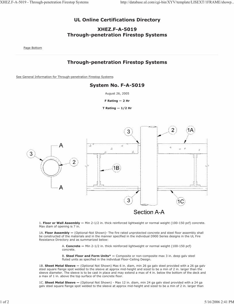
XHEZ.F-A-5019 - Through-penetration Firestop Systems http://database.ul.com/cgi-bin/XYV/template/LISEXT/1FRAME/showp...
1 of 2 5/16/2006 2:41 PM
UL Online Certifications Directory
XHEZ.F-A-5019Through-penetration Firestop Systems
Page Bottom
Through-penetration Firestop Systems
See General Information for Through-penetration Firestop Systems
System No. F-A-5019
August 26, 2005
F Rating — 2 Hr
T Rating — 1/2 Hr
1. Floor or Wall Assembly — Min 2-1/2 in. thick reinforced lightweight or normal weight (100-150 pcf) concrete.Max diam of opening is 7 in.
1A. Floor Assembly — (Optional-Not Shown)- The fire rated unprotected concrete and steel floor assembly shallbe constructed of the materials and in the manner specified in the individual D900 Series designs in the UL Fire Resistance Directory and as summarized below:
A. Concrete — Min 2-1/2 in. thick reinforced lightweight or normal weight (100-150 pcf)concrete.
B. Steel Floor and Form Units* — Composite or non-composite max 3 in. deep galv steelfluted units as specified in the individual Floor-Ceiling Design.
1B. Sheet Metal Sleeve — (Optional Not Shown) Max 6 in. diam, min 26 ga galv steel provided with a 26 ga galvsteel square flange spot welded to the sleeve at approx mid-height and sized to be a min of 2 in. larger than the sleeve diameter. The sleeve is to be cast in place and may extend a max of 4 in. below the bottom of the deck anda max of 1 in. above the top surface of the concrete floor.
1C. Sheet Metal Sleeve — (Optional Not Shown) - Max 12 in. diam, min 24 ga galv steel provided with a 24 gagalv steel square flange spot welded to the sleeve at approx mid-height and sized to be a min of 2 in. larger than

XHEZ.F-A-5019 - Through-penetration Firestop Systems http://database.ul.com/cgi-bin/XYV/template/LISEXT/1FRAME/showp...
2 of 2 5/16/2006 2:41 PM
the sleeve diameter. The sleeve is to be cast in place and may extend a max of 4 in. below the bottom of the deckand a max of 1 in. above the top surface of the concrete floor.
2. Through Penetrants — One metallic pipe or tubing to be installed within the firestop device. Pipe or tubing tobe rigidly supported on both sides of floor assembly. The following types of pipe or tubing may be used.
Steel Pipe — Nom 4 in. diam (or smaller) Schedule 10 (or heavier) steel pipe.
Copper Tubing — Nom 4 in. diam (or smaller) Type L (or heavier) copper tubing.
Copper Pipe — Nom 4 in. diam (or smaller) Regular (or heavier) copper pipe.
3. Tube Insulation - Plastics+ — Nom 3/4 in. thick acryonitrile butadiene/polyvinyl chloride (AB/PVC) flexiblefoam furnished in the form of tubing. The annular space shall be min 0 in. (point contact) to max 1-3/8 in.
See Plastics+ (QMFZ2) Category in the Plastics Recognized Component Directory for names of manufacturers. Any Recognized Component tube insulation material meeting the above specifications and having a UL94 Flammability Classification of 94-5VA may be used.
4. Packing Material — Min 2 in. thickness of min 4 pcf mineral wool batt insulation firmly packed into opening asa permanent form. Packing material to be recessed from top surface of floor as required to accommodate the required thickness of fill material.
5. Fill, Void or Cavity Material*- Sealant — Min 1/2 in. thickness of fill material applied within the annulus, flushwith the top surface of floor. At point contact a min 1/2 in. bead of fill material shall be applied at the concrete/pipe interface on top surface of floor.
HILTI CONSTRUCTION CHEMICALS, DIV OF
HILTI INC — FS-ONE Sealant
*Bearing the UL Classification Mark
Last Updated on 2005-08-26
Questions? Notice of Disclaimer Page Top
Copyright © 2006 Underwriters Laboratories Inc.®
The appearance of a company's name or product in this database does not in itself assure that products so identified have been manufactured under UL's Follow-Up Service. Only those products bearing the UL Mark should be considered to be Listed and covered underUL's Follow-Up Service. Always look for the Mark on the product.
UL permits the reproduction of the material contained in the Online Certification Directory subject to the following conditions: 1. The Guide Information, Designs and/or Listings (files) must be presented in their entirety and in a non-misleading manner, without any manipulationof the data (or drawings). 2. The statement "Reprinted from the Online Certifications Directory with permission from UnderwritersLaboratories Inc." must appear adjacent to the extracted material. In addition, the reprinted material must include a copyright notice in thefollowing format: "Copyright © 2006 Underwriters Laboratories Inc.®"
XHEZ.F-A-5021 - Through-penetration Firestop Systems http://database.ul.com/cgi-bin/XYV/template/LISEXT/1FRAME/showp...
1 of 2 5/16/2006 2:40 PM
UL Online Certifications Directory
XHEZ.F-A-5021Through-penetration Firestop Systems
Page Bottom
Through-penetration Firestop Systems
See General Information for Through-penetration Firestop Systems
System No. F-A-5021
February 27, 2006
F Rating — 2 Hr
T Rating — 0 Hr
L Rating At Ambient — 4 CFM/Sq Ft
L Rating At 400 F — Less Than 1 CFM/Sq Ft
1. Floor Assembly — Min 2-1/2 in. thick reinforced lightweight or normal weight (100-150 pcf) concrete. Maxdiam of opening is 18 in.
1A. Floor Assembly — (Optional — Not Shown) — The fire rated unprotected concrete and steel floor assemblyshall be constructed of the materials and in the manner specified in the individual D900 Series designs in the ULFire Resistance Directory and as summariezed below:
A. Concrete — Min 2-1/2 in. thick reinforced lightweight on normal weight (100-150 pcf)concrete.
B. Steel Floor and Form Units* — Composite or non-composite max 3 in. deep galv steelfluted units as specified in the individual Floor-Ceiling Design.
2. Metallic Sleeve — (Optional) — Nom 18 in. diam (or smaller) Schedule 10 (or heavier) steel pipe.
2A. Sheet Metal Sleeve — (Optional) Max 6 in. diam, min 26 ga galv steel provided with a 26 ga galv steel square

XHEZ.F-A-5021 - Through-penetration Firestop Systems http://database.ul.com/cgi-bin/XYV/template/LISEXT/1FRAME/showp...
2 of 2 5/16/2006 2:40 PM
flange spot welded to the sleeve at approx mid-height and sized to be a min of 2 in. larger than the sleeve diam. The sleeve is to be cast in place and may extend a max of 4 in. below the bottom of the floor and a max of 1 in. above the top surface of the floor.
2B. Sheet Metal Sleeve — (Optional) - Max 12 in. diam, min 24 ga galv steel provided with a 24 ga galv steelsquare flange spot welded to the sleeve at approx mid-height and sized to be a min of 2 in. larger than the sleeve diam. The sleeve is to be cast in place and may extend a max of 4 in. below the bottom of the floor and a max of 1in. above the top surface of the floor.
3. Through-Penetrant — One metallic pipe or tubing to be installed within the firestop device. Pipe or tubing to berigidly supported on both sides of floor assembly. The following types of pipe or tubing may be used:
Steel Pipe — Nom 12 in. diam (or smaller) Schedule 10 (or heavier) steel pipe.
Copper Tubing — Nom 6 in. diam (or smaller) Type L (or heavier) copper tubing.
Copper Pipe — Nom 6 in. diam (or smaller) Regular (or heavier) copper pipe.
4. Pipe Covering* — Nom 1-1/2 in. thick hollow cylindrical heavy density (min 3.5 pcf) glass fiber units, jacketedon the outside with an all service jacket. Longitudinal joints sealed with metal fasteners or factory-applied SSL tape. Transverse joints secured with metal fasteners or with butt tape supplied with the product. The annular spacebetween the insulated pipe and the periphery of the opening shall be min 1/2 in. to a max 1-7/8 in.
See Pipe Equipment Covering — Materials (BRGU) category in the Building Materials Directory for names of manufacturers. Any pipe covering material meeting the above specifications and bearing the UL Classification Marking with a Flame Spread Index of 25 or less and a Smoke Developed Index of 50 or less may be used.
5. Firestop System — The firestop system shall consist of the following:
A. Packing Material — Min 1-1/2 in. thickness of min 4 pcf mineral wool batt insulationfirmly packed into opening as a permanent form. Packing material to be recessed from top surface of floor as required to accommodate the required thickness of fill material.
B. Fill, Void or Cavity Material* — Sealant — Min 1 in. thickness of fill material appliedwithin the annulus, flush with top surface of floor. In addition, when steel sleeve extendsbeyond top surface of floor, a min 3/8 in. bead of sealant shall be applied at the interface of the sleeve and concrete around periphery of opening at top surface of floor.
HILTI CONSTRUCTION CHEMICALS, DIV OF
HILTI INC — FS-ONE Sealant
*Bearing the UL Classification Mark
Last Updated on 2006-02-27
Questions? Notice of Disclaimer Page Top
Copyright © 2006 Underwriters Laboratories Inc.®
The appearance of a company's name or product in this database does not in itself assure that products so identified have been manufactured under UL's Follow-Up Service. Only those products bearing the UL Mark should be considered to be Listed and covered underUL's Follow-Up Service. Always look for the Mark on the product.
UL permits the reproduction of the material contained in the Online Certification Directory subject to the following conditions: 1. The Guide Information, Designs and/or Listings (files) must be presented in their entirety and in a non-misleading manner, without any manipulationof the data (or drawings). 2. The statement "Reprinted from the Online Certifications Directory with permission from UnderwritersLaboratories Inc." must appear adjacent to the extracted material. In addition, the reprinted material must include a copyright notice in thefollowing format: "Copyright © 2006 Underwriters Laboratories Inc.®"

XHEZ.W-J-1067 - Through-penetration Firestop Systems http://database.ul.com/cgi-bin/XYV/template/LISEXT/1FRAME/showp...
1 of 2 5/16/2006 12:11 PM
UL Online Certifications Directory
XHEZ.W-J-1067Through-penetration Firestop Systems
Page Bottom
Through-penetration Firestop Systems
See General Information for Through-penetration Firestop Systems
System No. W-J-1067
December 04, 2002
F Ratings — 1 and 2 Hr (See Items 1 and 3)
T Rating — 0 Hr
L Rating at Ambient—Less Than 1 CFM/Sq Ft
L Rating At 400 F—4 CFM/Sq Ft
1. Wall Assembly — Min 3-3/4 in. and 5 in. thick reinforced lightweight or normal weight (100-150 pcf) concretefor 1 and 2 h rated assemblies, respectively. Wall may also be constructed of any UL Classified Concrete Blocks*.Max diam of opening is 32-1/4 in.
See Concrete Blocks (CAZT) category in the Fire Resistance Directory for names of manufacturers.
2. Through—Penetrants — One metallic pipe, conduit or tubing to be centered within the firestop system. Theannular space shall be min 0 in. to max 2-1/4 in. Pipe may be installed with continuous point contact. Pipe, conduitor tube may be installed at an an angle not greater than 45 degrees from perpendicular. Pipe, conduit or tubing tobe rigidly supported on both sides of wall assembly. The following types and sizes of metallic pipes, conduits or tubing may be used:
A. Steel Pipe — Nom 30 in. diam (or smaller) Schedule 10 (or heavier) steel pipe.
B. Iron Pipe — Nom 30 in. diam (or smaller) cast or ductile iron pipe.
XHEZ.W-J-1067 - Through-penetration Firestop Systems http://database.ul.com/cgi-bin/XYV/template/LISEXT/1FRAME/showp...
2 of 2 5/16/2006 12:11 PM
C. Conduit — Nom 4 in. diam (or smaller) steel electrical metallic tubing or 6 in. diam (orsmaller) steel conduit.
D. Copper Tubing — Nom 6 in. diam (or smaller) Type L (or heavier) copper tubing.
E. Copper Pipe — Nom 6 in. diam (or smaller) Regular (or heavier) copper pipe.
3. Fill, Void or Cavity Material* — Min 5/8 in. thickness of fill material applied within the annulus, flush with bothsurfaces of wall. At the point or continuous contact locations between pipe and wall, a min 1/2 in. diam bead of fill material shall be applied at the pipe-wall interface on both surfaces of wall.
HILTI CONSTRUCTION CHEMICALS, DIV OF
HILTI INC — FS-One Sealant
*Bearing the UL Classification Mark
Last Updated on 2002-12-04
Questions? Notice of Disclaimer Page Top
Copyright © 2006 Underwriters Laboratories Inc.®
The appearance of a company's name or product in this database does not in itself assure that products so identified have been manufactured under UL's Follow-Up Service. Only those products bearing the UL Mark should be considered to be Listed and covered underUL's Follow-Up Service. Always look for the Mark on the product.
UL permits the reproduction of the material contained in the Online Certification Directory subject to the following conditions: 1. The Guide Information, Designs and/or Listings (files) must be presented in their entirety and in a non-misleading manner, without any manipulationof the data (or drawings). 2. The statement "Reprinted from the Online Certifications Directory with permission from UnderwritersLaboratories Inc." must appear adjacent to the extracted material. In addition, the reprinted material must include a copyright notice in thefollowing format: "Copyright © 2006 Underwriters Laboratories Inc.®"
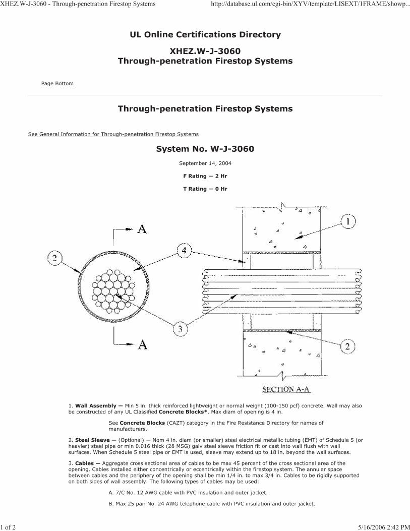
XHEZ.W-J-3060 - Through-penetration Firestop Systems http://database.ul.com/cgi-bin/XYV/template/LISEXT/1FRAME/showp...
1 of 2 5/16/2006 2:42 PM
UL Online Certifications Directory
XHEZ.W-J-3060Through-penetration Firestop Systems
Page Bottom
Through-penetration Firestop Systems
See General Information for Through-penetration Firestop Systems
System No. W-J-3060
September 14, 2004
F Rating — 2 Hr
T Rating — 0 Hr
1. Wall Assembly — Min 5 in. thick reinforced lightweight or normal weight (100-150 pcf) concrete. Wall may alsobe constructed of any UL Classified Concrete Blocks*. Max diam of opening is 4 in.
See Concrete Blocks (CAZT) category in the Fire Resistance Directory for names of manufacturers.
2. Steel Sleeve — (Optional) — Nom 4 in. diam (or smaller) steel electrical metallic tubing (EMT) of Schedule 5 (orheavier) steel pipe or min 0.016 thick (28 MSG) galv steel sleeve friction fit or cast into wall flush with wallsurfaces. When Schedule 5 steel pipe or EMT is used, sleeve may extend up to 18 in. beyond the wall surfaces.
3. Cables — Aggregate cross sectional area of cables to be max 45 percent of the cross sectional area of theopening. Cables installed either concentrically or eccentrically within the firestop system. The annular space between cables and the periphery of the opening shall be min 1/4 in. to max 3/4 in. Cables to be rigidly supported on both sides of wall assembly. The following types of cables may be used:
A. 7/C No. 12 AWG cable with PVC insulation and outer jacket.
B. Max 25 pair No. 24 AWG telephone cable with PVC insulation and outer jacket.
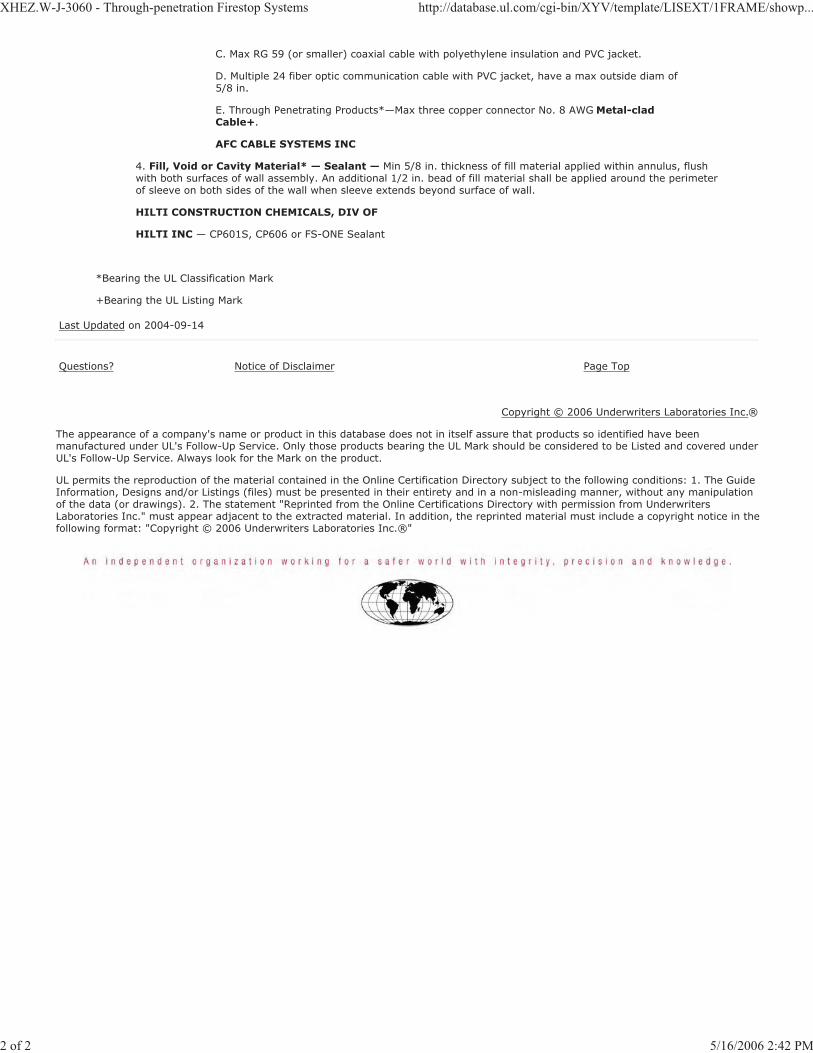
XHEZ.W-J-3060 - Through-penetration Firestop Systems http://database.ul.com/cgi-bin/XYV/template/LISEXT/1FRAME/showp...
2 of 2 5/16/2006 2:42 PM
C. Max RG 59 (or smaller) coaxial cable with polyethylene insulation and PVC jacket.
D. Multiple 24 fiber optic communication cable with PVC jacket, have a max outside diam of5/8 in.
E. Through Penetrating Products*—Max three copper connector No. 8 AWG Metal-cladCable+.
AFC CABLE SYSTEMS INC
4. Fill, Void or Cavity Material* — Sealant — Min 5/8 in. thickness of fill material applied within annulus, flushwith both surfaces of wall assembly. An additional 1/2 in. bead of fill material shall be applied around the perimeter of sleeve on both sides of the wall when sleeve extends beyond surface of wall.
HILTI CONSTRUCTION CHEMICALS, DIV OF
HILTI INC — CP601S, CP606 or FS-ONE Sealant
*Bearing the UL Classification Mark
+Bearing the UL Listing Mark
Last Updated on 2004-09-14
Questions? Notice of Disclaimer Page Top
Copyright © 2006 Underwriters Laboratories Inc.®
The appearance of a company's name or product in this database does not in itself assure that products so identified have been manufactured under UL's Follow-Up Service. Only those products bearing the UL Mark should be considered to be Listed and covered underUL's Follow-Up Service. Always look for the Mark on the product.
UL permits the reproduction of the material contained in the Online Certification Directory subject to the following conditions: 1. The Guide Information, Designs and/or Listings (files) must be presented in their entirety and in a non-misleading manner, without any manipulationof the data (or drawings). 2. The statement "Reprinted from the Online Certifications Directory with permission from UnderwritersLaboratories Inc." must appear adjacent to the extracted material. In addition, the reprinted material must include a copyright notice in thefollowing format: "Copyright © 2006 Underwriters Laboratories Inc.®"
XHEZ.W-J-5041 - Through-penetration Firestop Systems http://database.ul.com/cgi-bin/XYV/template/LISEXT/1FRAME/showp...
1 of 2 5/16/2006 2:43 PM
UL Online Certifications Directory
XHEZ.W-J-5041Through-penetration Firestop Systems
Page Bottom
Through-penetration Firestop Systems
See General Information for Through-penetration Firestop Systems
System No. W-J-5041
February 08, 2006
F Ratings — 1 and 2 Hr (See Item 1)
T Ratings — 3/4 Hr
L Rating at Ambient — Less Than 1 CFM/sq ft
L Rating at 400 F — Less Than 1 CFM/sq ft
1. Wall Assembly — Min 3-3/4 in. and 5 in. thick reinforced lightweight or normal weight (100-150 pcf) concretefor 1 and 2 h rated assemblies respectively. Wall may also be constructed of any UL Classified Concrete Blocks*. Max diam of opening is 7-1/2 in.
See Concrete Blocks (CAZT) category in the Fire Resistance Directory for names of manufacturers.
2. Through— Penetrants — One metallic pipe or tubing to be centered within the firestop system. Pipe or tubingto be rigidly supported on both sides of wall assembly. The following types and sizes of metallic pipes or tubing may be used:
A. Steel Pipe — Nom 4 in. diam (or smaller) Schedule 40 (or heavier) steel pipe.
B. Copper Tubing — Nom 2 in. diam (or smaller) Type L (or heavier) copper tubing.
C. Copper Pipe — Nom 2 in. diam (or smaller) regular (or heavier) copper pipe.

XHEZ.W-J-5041 - Through-penetration Firestop Systems http://database.ul.com/cgi-bin/XYV/template/LISEXT/1FRAME/showp...
2 of 2 5/16/2006 2:43 PM
3. Tube Insulation—Plastics+ — Nom 3/4 in. thick acrylonitrile butadiene/polyvinyl chloride (AB/PVC) flexiblefoam furnished in the form of tubing. An annular space of min 0 in. (point contact) to max 1-1/2 in. is required within the firestop system.
See Plastics+ (QMFZ2) category in the Recognized Component Directory for names of manufacturers. Any Recognized Component tube insulation material meeting the above specifications and having a UL 94 Flammability Classification of 94-5VA may be used.
The hour T Rating of the firestop system is dependent on the size and type of through penetrant and the pipe diam, as shown in the table below:
Type+Through Penetrant
Max Diam, In.
A 4
A, B or C 2
+-Indicates penetrant type as itemized in Item 2.
4. Fill, Void or Cavity Material*—Sealant — Min 5/8 in. thickness of fill material applied within the annulus,flush with both surfaces of wall. At the point contact location between pipe covering and wall, a min 1/2 in. diam bead of fill material shall be applied at the pipe covering/wall interface on both surfaces of wall
HILTI CONSTRUCTION CHEMICALS, DIV OF
HILTI INC — FS-ONE Sealant
*Bearing the UL Classification Mark
Last Updated on 2006-02-08
Questions? Notice of Disclaimer Page Top
Copyright © 2006 Underwriters Laboratories Inc.®
The appearance of a company's name or product in this database does not in itself assure that products so identified have been manufactured under UL's Follow-Up Service. Only those products bearing the UL Mark should be considered to be Listed and covered underUL's Follow-Up Service. Always look for the Mark on the product.
UL permits the reproduction of the material contained in the Online Certification Directory subject to the following conditions: 1. The Guide Information, Designs and/or Listings (files) must be presented in their entirety and in a non-misleading manner, without any manipulationof the data (or drawings). 2. The statement "Reprinted from the Online Certifications Directory with permission from UnderwritersLaboratories Inc." must appear adjacent to the extracted material. In addition, the reprinted material must include a copyright notice in thefollowing format: "Copyright © 2006 Underwriters Laboratories Inc.®"

XHEZ.W-J-5042 - Through-penetration Firestop Systems http://database.ul.com/cgi-bin/XYV/template/LISEXT/1FRAME/showp...
1 of 3 5/16/2006 2:42 PM
UL Online Certifications Directory
XHEZ.W-J-5042Through-penetration Firestop Systems
Page Bottom
Through-penetration Firestop Systems
See General Information for Through-penetration Firestop Systems
System No. W-J-5042
February 08, 2006
F Ratings — 1 and 2 Hr (See Items 1 and 4)
T Ratings — 1/2, 3/4, 1, 1-1/2 and 1-3/4 Hr (See Item 3)
L Rating At Ambient — 4 CFM/Sq Ft
L Rating at 400 F — Less Than 1 CFM/Sq Ft
1. Wall Assembly — Min 3-3/4 in. and 5 in. thick reinforced lightweight or normal weight (100-150 pcf) concretefor 1 and 2 h rated assemblies, respectively. Wall may also be constructed of any UL Classified Concrete Blocks*.Max diam of opening is 18-5/8 in.
See Concrete Blocks (CAZT) category in the Fire Resistance Directory for names of manufacturers.
2. Through—Penetrants — One metallic pipe or tubing to be centered within the firestop system. Pipe or tubingto be rigidly supported on both sides of wall assembly. The following types and sizes of metallic pipes or tubing

XHEZ.W-J-5042 - Through-penetration Firestop Systems http://database.ul.com/cgi-bin/XYV/template/LISEXT/1FRAME/showp...
2 of 3 5/16/2006 2:42 PM
may be used:
A. Steel Pipe — Nom 12 in. diam (or smaller) Schedule 10 (or heavier) steel pipe.
B. Iron Pipe — Nom 12 in. diam (or smaller) cast or ductile iron pipe.
C. Copper Tubing — Nom 6 in. diam (or smaller) Type L (or heavier) copper tubing.
D. Copper Pipe — Nom 6 in. diam (or smaller) Regular (or heavier) copper pipe.
3. Pipe Covering* — Nom 1, 1-1/2 or 2 in. thick hollow-cylindrical heavy density (min 3.5 pcf) glass fiber unitsjacketed on the outside with an all service jacket. Longitudinal joints sealed with metal fasteners or factory-applied self-sealing lap tape. Transverse joints secured with metal fasteners or with butt tape supplied with the product.
See Pipe and Equipment Covering Materials (BRGU) category in the Building Materials Directory for the namesof the manufacturers. Any pipe covering material meeting the above specifications and bearing the UL ClassificationMarking with a Flame Spread Index of 25 or less and a Smoke Developed Index of 50 or less may be used.
The hourly T Rating of the firestop system is dependent on the size and type of through penetrant, the pipe covering thickness and the annular space as shown in the the table below:
WallAssembly
RatingHr
ThroughPenetrant Pipe
CoveringThkns
In.
Annular Space
TRating
HrType +Max Diam
In.MinIn.
MaxIn.
1 A, B 4 1 0 1-1/2 1/2
1 C or D 2 1 or 1-1/2 0 1-1/2 1/2
1 A, B 4 1-1/2 0 1-1/2 1
1 A, B 10 2 0 1-7/8 3/4
1 C or D 6 2 0 1-7/8 1
2 A, B 4 1 0 1-1/2 1
2 C or D 4 1 or 1-1/2 0 1-1/2 1
2 A, B 4 1-1/2 0 1-1/2 1-3/4
2 A, B 12 2 0 1-7/8 1-1/2
2 C or D 6 2 0 1-7/8 1
+-Indicates penetrant type as itemized in Item 2.
4. Fill, Void or Cavity Material*—Sealant — Min 5/8 in. thickness of fill material applied within the annulus,flush with both surfaces of wall. At the point contact location between pipe covering and wall, a min 1/2 in. diam bead of fill material shall be applied at the pipe covering/wall interface on both surfaces of wall.
HILTI CONSTRUCTION CHEMICALS, DIV OF
HILTI INC — FS-One Sealant
*Bearing the UL Classification Mark
Last Updated on 2006-02-08
Questions? Notice of Disclaimer Page Top
Copyright © 2006 Underwriters Laboratories Inc.®
The appearance of a company's name or product in this database does not in itself assure that products so identified have been manufactured under UL's Follow-Up Service. Only those products bearing the UL Mark should be considered to be Listed and covered underUL's Follow-Up Service. Always look for the Mark on the product.
UL permits the reproduction of the material contained in the Online Certification Directory subject to the following conditions: 1. The Guide Information, Designs and/or Listings (files) must be presented in their entirety and in a non-misleading manner, without any manipulationof the data (or drawings). 2. The statement "Reprinted from the Online Certifications Directory with permission from UnderwritersLaboratories Inc." must appear adjacent to the extracted material. In addition, the reprinted material must include a copyright notice in thefollowing format: "Copyright © 2006 Underwriters Laboratories Inc.®"

XHEZ.W-J-5042 - Through-penetration Firestop Systems http://database.ul.com/cgi-bin/XYV/template/LISEXT/1FRAME/showp...
3 of 3 5/16/2006 2:42 PM

XHEZ.W-J-7022 - Through-penetration Firestop Systems http://database.ul.com/cgi-bin/XYV/template/LISEXT/1FRAME/showp...
1 of 2 5/16/2006 2:43 PM
UL Online Certifications Directory
XHEZ.W-J-7022Through-penetration Firestop Systems
Page Bottom
Through-penetration Firestop Systems
See General Information for Through-penetration Firestop Systems
System No. W-J-7022
November 30, 2000
F Ratings — 1 and 2 Hr (See Items 1 and 3)
T Rating — 0 Hr
1. Wall Assembly — Min 3-3/4 in. and 5 in. thick reinforced lightweight or normal weight (100-150 pcf) concretefor 1 and 2 hr ratings , respectively. Wall may also be constructed of any UL Classified Concrete Blocks*. Maxdiam of opening is 21- 1/2 in.
See Concrete Blocks (CAZT) category in the Fire Resistance Directory for names ofmanufacturers.
2. Through Penetrant — Nom galv steel duct to be installed concentrically or eccentrically within the firestopsystem. The annular space between duct and periphery of opening shall be min 0 in. (point contact) and max 1-1/2in. Duct to be rigidly supported on both sides of wall assembly.
A. Spiral Wound HVAC Duct — Nom 20 in. diam (or smaller) No. 24 MSG (or heavier)galv steel spiral wound duct.

XHEZ.W-J-7022 - Through-penetration Firestop Systems http://database.ul.com/cgi-bin/XYV/template/LISEXT/1FRAME/showp...
2 of 2 5/16/2006 2:43 PM
A. Sheet Metal Duct — Nom 12 in. diam (or smaller) No. 28 MSG (or heavier) galv sheetsteel duct.
3. Fill, Void or Cavity Material* — Sealant — Min 5/8 in. and 1-1/4 in. thickness of fill material applied withinannulus, flush with both surfaces of wall assembly for 1 or 2 hr F Ratings, respectively. At the point contact location between duct and periphery of opening, a min 1/2 in. diam bead of sealant shall be applied at the periphery/duct interface on both surfaces of wall assembly.
HILTI CONSTRUCTION CHEMICALS, DIV OF
HILTI INC — CP 601S Elastomeric Firestop Sealant, FS-ONE Sealant or CP606 Flexible Firestop Sealant
*Bearing the UL Classification Mark
Last Updated on 2000-11-30
Questions? Notice of Disclaimer Page Top
Copyright © 2006 Underwriters Laboratories Inc.®
The appearance of a company's name or product in this database does not in itself assure that products so identified have been manufactured under UL's Follow-Up Service. Only those products bearing the UL Mark should be considered to be Listed and covered underUL's Follow-Up Service. Always look for the Mark on the product.
UL permits the reproduction of the material contained in the Online Certification Directory subject to the following conditions: 1. The Guide Information, Designs and/or Listings (files) must be presented in their entirety and in a non-misleading manner, without any manipulationof the data (or drawings). 2. The statement "Reprinted from the Online Certifications Directory with permission from UnderwritersLaboratories Inc." must appear adjacent to the extracted material. In addition, the reprinted material must include a copyright notice in thefollowing format: "Copyright © 2006 Underwriters Laboratories Inc.®"
[BSA Job No.] FIRESTOPPING07 84 00 (07840)
2006
FIRESTOPPING DRAWINGS
CONCRETE TOP-OF-WALL ASSEMBLIES
CONCRETE MASONRY UNIT (CMU)
TOP-OF-WALL ASSEMBLIES
08033.
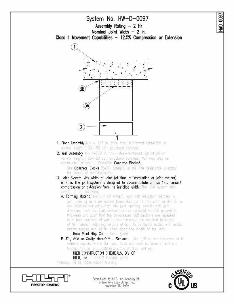

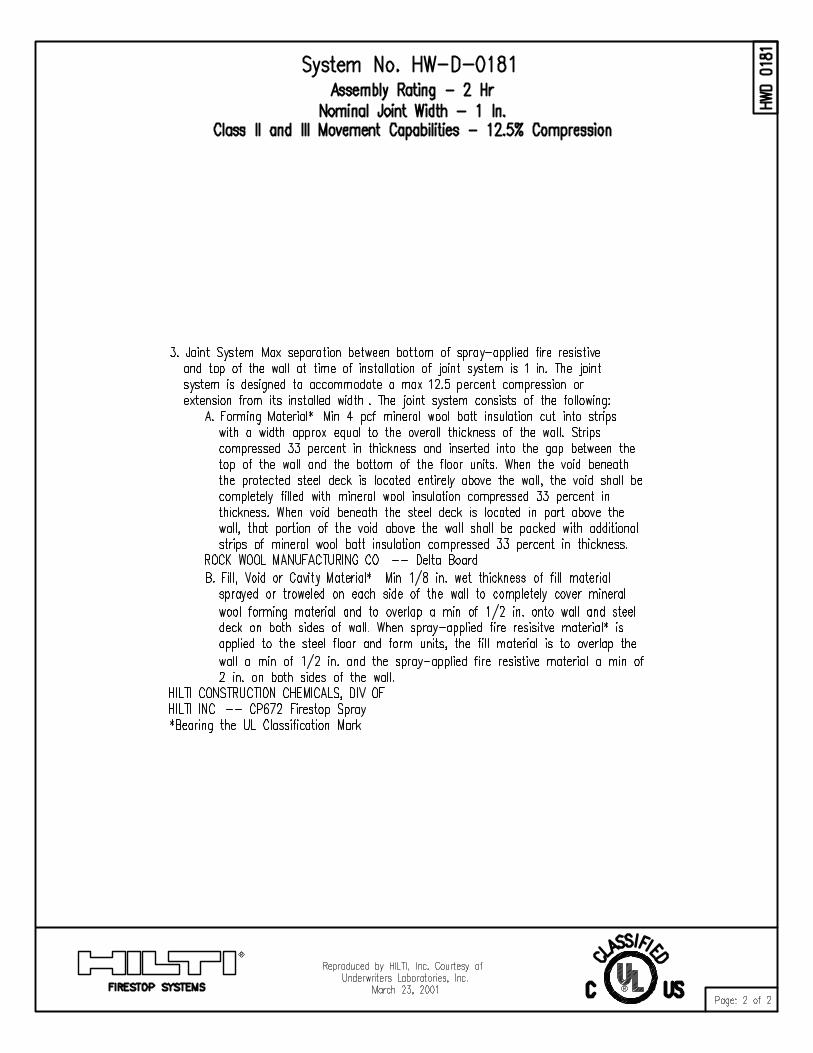
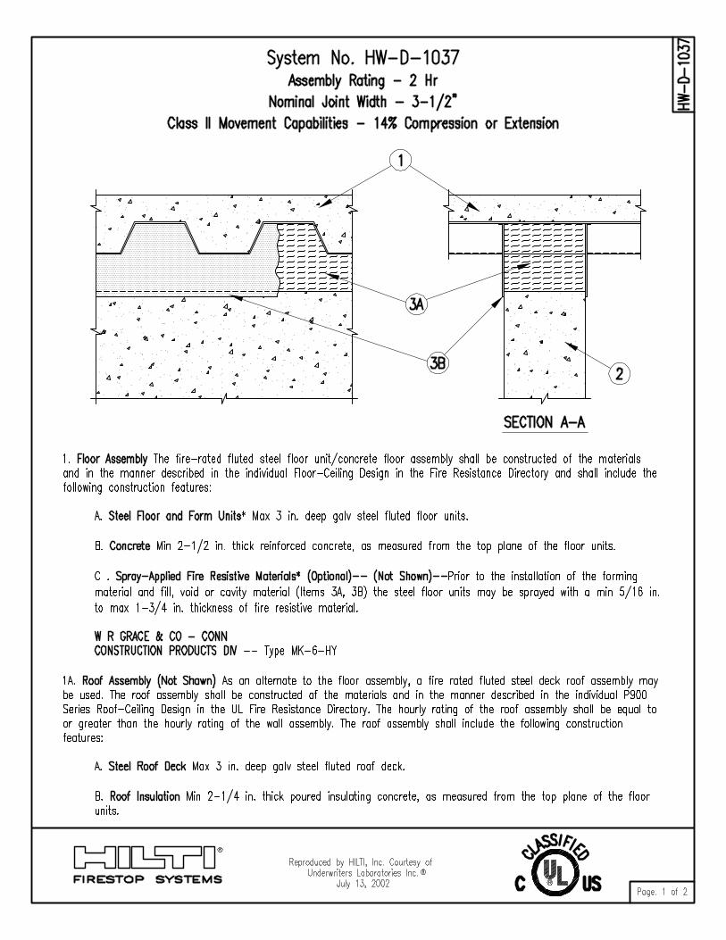
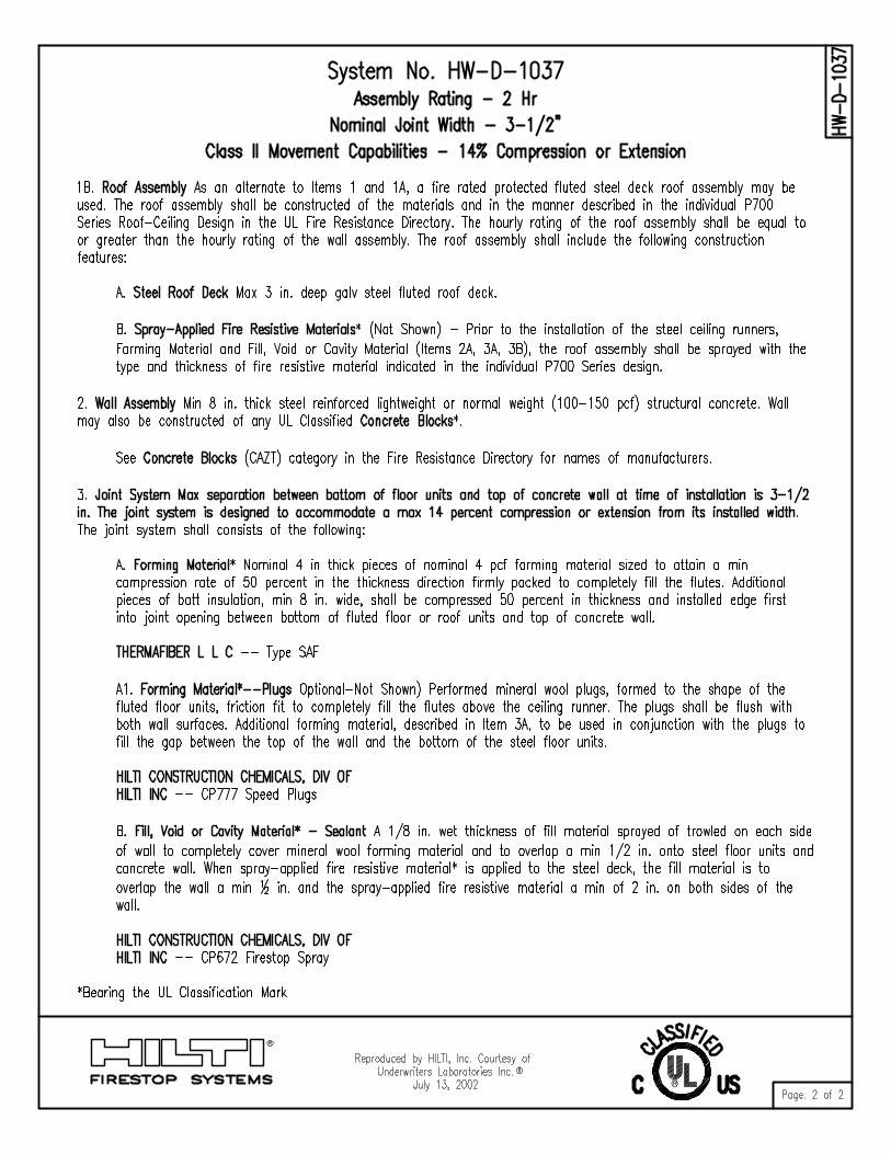
11044 JOINT SEALANTS
07 92 00-1 12-13-13
SECTION 07 92 00
JOINT SEALANTS
PART 1 GENERAL
1.01 SUMMARY
A. Section Includes:
1. Sealant and Backing Materials including primers, backer rods, bond breakers and accessories.
2. Clean and Prepare Joint Surfaces
B. Related Sections:
1. Section 03 30 00 - Cast-in-Place Concrete
2. Section 07 84 00 - Firestopping
3. Section 09 90 00 - Painting
1.02 REFERENCES
A. ASTM International Publications:
1. C834 “Standard Specification for Latex Sealants”
2. C920 “Standard Specification for Elastomeric Joint Sealants”
3. C1193 "Standard Guide for Use of Joint Sealants"
4. C1248 “Standard Test Method for Staining of Porous Substrate by Joint Sealants”
B. Code of Federal Regulations (CFR) Publications:
1. 21 CFR, Part 177 “Indirect Food Additives: Polymers”
C. Federal Specifications (FS) Publications:
1. TT-S-1543B Sealing Compound; Silicone Rubber Base (For Caulking, Sealing)
D. Underwriter's Laboratories, Inc. (UL) Standards
1. "Fire Resistance Directory"
E. Warnock Hersey, ETL SEMKO division of Intertek (WHI) Publications:
1. "Certification Listings"
1.03 SYSTEM DESCRIPTION
A. Work shall include providing sealant at intersection of construction components within and exterior to building, including, but not limited to the following:
1. Exterior joints in the following vertical surfaces and non-traffic horizontal surfaces:
a. Control and expansion joints in cast-in-place concrete.
b. Control and expansion joints in unit masonry.
c. Joints between metal panels.
d. Joints between different materials listed above.
e. Perimeter joints between materials listed above and frames of doors and windows.
f. Control and expansion joints in ceiling and overhead surfaces.
g. Under thresholds.

11044 JOINT SEALANTS
07 92 00-2 12-13-13
h. Refrigerant lines and other Div. 22, 23 and 26 items entering building.
i. Joints in coping caps and exposed roof counter flashing.
j. Other joints as indicated.
2. Exterior joints in the following horizontal traffic surfaces:
a. Control, expansion, and isolation joints in cast-in-place concrete slabs.
b. Joints between different materials listed above.
c. Other joints as indicated.
3. Interior joints in the following vertical surfaces and horizontal non-traffic surfaces:
a. Control and expansion joints on exposed interior surfaces of exterior walls.
b. Perimeter joints of exterior openings where indicated.
c. Vertical control joints on exposed surfaces of interior unit masonry and concrete walls and partitions.
d. Perimeter joints between interior wall surfaces and frames of interior doors, windows, and elevator entrances.
e. Other joints as indicated
4. Interior joints in the following horizontal traffic surfaces:
a. Control and expansion joints in cast-in-place concrete slabs.
b. Under thresholds.
c. Door bucks not flush with thresholds.
d. Other joints as indicated.
1.04 SUBMITTALS
A. General: Submit the following in accordance with Conditions of Contract and Division 01 Specification Sections:
1. Include product data, samples and manufacturer's surface preparation and installation instructions.
2. List of primers recommended for each application.
3. Submit samples of each color required for each type of joint sealer exposed to view in duplicate.
4. Certifications: Indicate compliance with standards specified in duplicate.
1.05 QUALITY ASSURANCE
A. Installer Qualifications: An experienced installer who has specialized in installing joint sealants similar in material, design, and extent to those indicated for this Project and whose work has resulted in joint-sealant installations with a record of successful in-service performance.
B. Source Limitations: Obtain each type of joint sealant through one source from a single manufacturer.
C. All materials shall be verified by this Contractor to be compatible with adjacent materials.
1.06 DELIVERY, STORAGE, AND HANDLING
A. Deliver materials to Project site in original unopened containers or bundles with labels indicating manufacturer, product name and designation, color, expiration date, pot life, curing time, and mixing instructions for multicomponent materials.
11044 JOINT SEALANTS
07 92 00-3 12-13-13
B. Store and handle materials in compliance with manufacturer's written instructions to prevent their deterioration or damage due to moisture, high or low temperatures, contaminants, or other causes.
1.07 PROJECT CONDITIONS
A. Environmental Limitations: Do not proceed with installation of joint sealants under the following conditions:
1. When ambient and substrate temperature conditions are outside limits permitted by joint sealant manufacturer or are below 40 degrees F. and less than 100 degrees F.
2. When joint substrates are wet.
B. Joint-Width Conditions: Do not proceed with installation of joint sealants where joint widths are less than those allowed by joint sealant manufacturer for applications indicated.
1.08 WARRANTY
A. Special Warranty:
1. Submit two copies of a written guarantee agreeing to repair or replace joint sealers which fail to perform as air tight and water-tight joints; or fail in joint adhesion, cohesion, abrasion resistance weather resistance, or general durability; or appear to deteriorate or become unserviceable or causing an objectionable appearance resulting from either defective or non-conforming materials and workmanship or in any other manner not clearly specified by submitted manufacturer's data as an inherent quality of the material for the exposure indicated. Provide one-year Warranty.
a. Defects shall include, but are not limited to:
1) Staining from abutting materials or filler.
2) Migrating, bleeding into, or staining abutting materials.
3) Unsightly surface deformation by causes other than movement.
4) Excessive color change, chalking, or dust pick-up.
5) Railing adhesively or cohesively where maximum elongation is less than 25% of designed width of exposed joints.
6) Hardening to more than 25% over specified hardness.
b. Replace sealants which fail because of loss of cohesion or adhesion or do not cure.
PART 2 PRODUCTS
2.01 SEALANTS
A. General:
1. Compatibility: Provide joint sealants, backings, and other related materials that are compatible with one another and with joint substrates under conditions of service and application, as demonstrated by joint-sealant manufacturer, based on testing and field experience.
2. VOC Content of Interior Sealants: Provide sealants and sealant primers for use inside the weatherproofing system that comply with the following limits for VOC content when calculated according to 40 CFR 59, Part 59, Subpart D (EPA Method 24):
a. Sealants to comply with SCAQMD #1168.
b. Architectural Sealants: 250 g/L.
c. Sealant Primers for Nonporous Substrates: 250 g/L.
d. Sealant Primers for Porous Substrates: 775 g/L.

11044 JOINT SEALANTS
07 92 00-4 12-13-13
3. Colors: As shown on Interior Finish Index and Exterior Finish Index, or if not shown, match sealant material to colors of adjacent materials, as approved by Owner's representative, unless indicated otherwise.
4. Elastomeric Sealant Standard: Comply with ASTM C 920 and other requirements indicated for each liquid-applied chemically curing sealant, including those referencing ASTM C 920 classifications for type, grade, class, and uses.
5. Stain-Test-Response Characteristics: Where elastomeric sealants are specified to be non-staining to porous substrates, provide products that have undergone testing according to ASTM C 1248 and have not stained porous joint substrates indicated for Project.
6. Suitability for Contact with Food: Where elastomeric sealants are indicated for joints that will come in repeated contact with food; provide products that comply with 21 CFR 177.2600.
B. Sanitary Sealant, Interior Use:
1. One component silicone rubber sealant, complying with ASTM C920, Type S, Grade NT, Class 25, and FS-TT-S-001543, Class A. Provide acid cure, nonporous bond type, mildew resistant silicone rubber where both joint faces are metal, glass, plastic, or other non-porous material.
2. Acceptable Products:
a. “Tremsil 600”; Tremco, Inc., an RPM Company (800-562-2728) VOC: 8 g/L
b. "Omni-Plus"; Sonneborn Bldg. Products Div., Degussa Building Systems (800-243-6739) VOC: 0 g/L
c. "786 Mildew Resistant“; Dow Corning Corp. (800-248-2481) VOC: 33 g/L
d. “Sanitary SCS1700”; General Electric (GE) Silicones (800-255-8886)
e. “898”; Pecora Corp. (800-523-6688) VOC: 40 g/L
C. Interior Joints not subject to Movement:
1. One part, gun grade, acrylic latex meeting the requirements of ASTM C 834 with 10 year life expectancy.
2. Acceptable Products:
a. "Tremflex 834”; Tremco, Inc. an RPM Company (800-562-2728) VOC: 11 g/L
b. "Chem-Calk 600"; Bostik Findley, Inc. (888-603-8558) VOC: 39 g/L
c. "AC-20"; Pecora Corp. (800-523-6688) 50 g/L
D. Interior Joints subject to Movement: One-part, non-sag acrylic Terpolymer formulation
1. FS-TT-S230 with 20-year life expectancy.
2. Colors: Match sealant material to colors of adjacent materials, as selected by Owner's Representative from manufacturer's standard colors.
3. Acceptable Products:
a. “Vulkem 921”; Tremco, Inc. , an RPM Company (800-562-2728) VOC: 61 g/L
b. “Dynatrol I”; Pecora Corp. (800-523-6688) VOC: 100g/L
c. "Dymonic"; Tremco, Inc., an RPM Company (800-562-2728) VOC: 50 g/L
d. "NP1"; Sonneborn Bldg. Products Div., Degussa Building Systems (800-243-6739) VOC: 43 g/L
11044 JOINT SEALANTS
07 92 00-5 12-13-13
E. Exterior joints greater than 1/2": Two-part non-sag, polyurethane type.
1. ASTM C920 with 20 year life expectancy.
2. Colors: Match sealant material to colors of adjacent materials, as selected by Owner's Representative from manufacturer's standard colors.
3. Acceptable Manufacturers:
a. "Dymeric 240 or 240FC" ; Tremco, Inc., an RPM Company (800-562-2728)
b. "Chem-Calk 2641"; Bostik Findley, Inc. (888-603-8558)
c. "Dynatrol II"; Pecora Corp. (800-523-6688)
d. "NP2"; Sonneborn Bldg. Products Div., Degussa Building Systems (800-243-6739)
F. Exterior joints less than 1/2": One-part, non-sag acrylic Terpolymer
1. ASTM C920 with 20-year life expectancy.
2. Colors: Match sealant material to colors of adjacent materials, as selected by Owner's Representative from manufacturer's standard colors.
3. Acceptable Manufacturers:
a. “Vulkem 911”; Tremco, Inc. , an RPM Company (800-562-2728)
b. “Dynatrol I”; Pecora Corp. (800-523-6688)
c. "Dymonic"; Tremco, Inc., an RPM Company (800-562-2728)
d. "NP1"; Sonneborn Bldg. Products Div., Degussa Building Systems (800-243-6739)
G. Exterior, Self-Leveling Horizontal Joints:
1. Multi-Component Pourable Urethane Sealant, Type M, Grade P, Class 25, Use T, M and O, and ASTM C920.
2. Acceptable Products
a. Typical Joints
1) “THC 900”; Tremco, Inc., an RPM Company (800-562-2728)
2) “Vulkem 245”; Tremco, Inc., an RPM Company (800-562-2728)
b. Joints up to 19mm (3/4”) maximum
1) “Tremflex SL”; Tremco, Inc., an RPM Company (800-562-2728)
2) “Vulkem 45”; Tremco, Inc., an RPM Company (800-562-2728)
H. Sealant Materials - Glazing:
1. Sealant composition shall be a silicone base, single component, solvent curing, capable of withstanding movement of up to 50 percent of joint width and shore a hardness of 26. Sealant shall conform to, ASTM C920, TTS-S-001543A and TT-S-00230C (COM-NBS).
2. Acceptable Products:
a. "SPECTRUM 2"; Tremco, Inc., an RPM Company (800-562-2728)
b. “SILGLAZE N"; General Electric (GE) Silicones (800-255-8886)
2.02 ACCESSORIES
A. Primer: Non-staining type, recommended by sealant manufacturer to suit application.
B. Joint Cleaner: Non-corrosive and non-staining type, recommended by sealant manufacturer; compatible with joint forming materials.

11044 JOINT SEALANTS
07 92 00-6 12-13-13
C. Joint Filler Backer Rod: ASTM D1056; D1565; round, closed cell polyethylene, non-gassing rod sized to produce 25% compression when installed in joint.
1. Approved Manufacturers:
a. " Ethafoam"; Dow Chemical (800-447-4361)
b. "Sonofoam Soft Backer Rod"; Sonneborn Bldg. Products Div., Degussa Building Systems (800-243-6739)
D. Bond Breaker Tape:
1. Approved Manufacturers:
a. Pressure Sensitive 470 or 481 Polyethylene"; 3M Adhesives, Coatings and Sealers Div., (800-328-1687)
b. Approved Substitution
E. Cleaners for Nonporous Surfaces: Provide non-staining, chemical cleaners of type which are acceptable to manufacturers of sealants and sealant backing materials, which are not harmful to substrates and adjacent nonporous materials, and which do not leave oily residues or otherwise have a detrimental effect on sealant adhesion or in-service performance.
1. Provide cleaner conditioner required for glass and glazed surfaces as recommended by sealant manufacturer.
F. Masking Tape: Provide non-staining, nonabsorbent type compatible with joint sealants and to surfaces adjacent to joints.
PART 3 EXECUTION
3.01 EXAMINATION
A. Examine joints indicated to receive joint sealers, with Installer present, for compliance with requirements for joint configuration, installation tolerances and other conditions affecting joint sealer performance. Do not proceed with installation of joint sealers until unsatisfactory conditions have been corrected. Beginning of Installation means acceptance of all existing conditions making this Contractor responsible for correcting all unsatisfactory and defective work encountered at his expense.
3.02 PREPARATION
A. Surface Cleaning of Joints: Clean out joints immediately before installing joint sealers to comply with recommendations of joint sealer manufacturers and the following requirements:
1. Remove all foreign material from joint substrates which could interfere with adhesion of joint sealer, including dust; paints, except for permanent, protective coatings tested and approved for sealant adhesion and compatibility by sealant manufacturer; old joint sealers; oil; grease; waterproofing; water repellents; water; surface dirt; and frost.
2. Clean concrete, masonry, and similar porous joint substrate surfaces, by brushing, grinding, blast cleaning, mechanical abrading, or a combination of these methods to produce a clean, sound substrate capable of developing optimum bond with joint sealers. Remove loose particles remaining from above cleaning operations by vacuuming or blowing out joints with oil-free compressed air. Remove laitance and form release agents from concrete.
B. Joint Priming: Prime joint substrates where indicated or where recommended by joint sealer manufacturer based on preconstruction joint sealer-substrate tests or prior experience. Apply primer to comply with joint sealer manufacturer's recommendations. Confine primers to areas of joint sealer bond; do not allow spillage or migration onto adjoining surfaces.

11044 JOINT SEALANTS
07 92 00-7 12-13-13
C. Masking Tape: Use masking tape where required to prevent contact of sealant with adjoining surfaces which otherwise would be permanently stained or damaged by such contact or by cleaning methods required to remove sealant smears such as masonry materials. Remove tape immediately after tooling without disturbing joint seal.
3.03 INSTALLATION OF JOINT SEALERS
A. General: Comply with joint sealer manufacturers' printed installation instructions applicable to products and applications indicated, except where more stringent requirements apply. Surfaces and air temperature shall be greater than 30 degrees F and less than 100 degrees F.
B. Joint Priming: Prime joint substrates where recommended in writing by joint sealant manufacturer, based on reconstruction joint-sealant-substrate tests or prior experience. Apply primer to comply with joint sealant manufacturer's written instructions. Confine primers to areas of joint-sealant bond; do not allow spillage or migration onto adjoining surfaces.
1. Ensure that primer fully covers surfaces to which sealant is to adhere.
2. Apply with bristle brush. Do not flood surfaces.
3. Allow primer to dry 30 minutes minimum or as recommended by manufacturer prior to application of backing rod and sealant.
C. Install sealant backings of type indicated to support sealants during application and at position required to produce cross-sectional shapes and depths of installed sealants relative to joint widths that allow optimum sealant movement capability.
1. Do not leave gaps between ends of sealant backings.
2. Do not stretch, twist, puncture, or tear sealant backings.
3. Remove absorbent sealant backings that have become wet before sealant application and replace them with dry materials.
D. Install bond breaker tape between sealants and joint fillers, compression seals, or back of joints where adhesion of sealant to surfaces at back of joints would result in sealant failure. Bond breaker must be used in all conditions where three-sided adhesion may be possible.
E. Install sealants by proven techniques to comply with the following and at the same time backings are installed:
1. Place sealants so they directly contact and fully wet joint substrates.
2. Completely fill recesses provided for each joint configuration.
3. Produce uniform, cross-sectional shapes and depths relative to joint widths that allow optimum sealant movement capability. Needle beads preferred at interior applications.
4. Joint Size:
a. Depth of joint shall not exceed width of joint.
b. Minimum depth: ¼”
c. Maximum depth: ½”
F. Tooling of Non-sag Sealants: Immediately after sealant application and before skinning or curing begins, tool sealants according to requirements specified below to form smooth, uniform beads of configuration indicated; to eliminate air pockets; and to ensure contact and adhesion of sealant with sides of joint.
1. Remove excess sealants from surfaces adjacent to joint.
2. Use tooling agents that are approved in writing by sealant manufacturer and that do not discolor sealants or adjacent surfaces.
11044 JOINT SEALANTS
07 92 00-8 12-13-13
a. Provide concave joint configuration per Figure 5A in ASTM C 1193, unless otherwise indicated.
b. Provide flush joint configuration, per Figure 5B in ASTM C 1193, where indicated.
c. Provide recessed joint configuration, per Figure 5C in ASTM C 1193, of recess depth and at locations indicated.
1) Use masking tape to protect adjacent surfaces of recessed tooled joints.
2) All joints shall be free of air pockets, foreign embedded matter, ridges, and sags.
3.04 CURE:
A. Cure sealant in compliance with manufacturer's instructions and recommendations to obtain high, early bond strength, internal cohesion strength and surface durability.
3.01 FIELD QUALITY CONTROL
A. Testing Agency: Owner will engage a qualified independent testing agency to oversee installation and to perform tests and inspections and prepare test reports.
B. Inspections: Sealant materials and installation are subject to inspection for compliance with requirements.
3.02 CLEANING:
A. Clean off excess sealants or sealant smears adjacent to joints as work progresses by methods and with cleaning materials approved by manufacturers of joint sealers and of products in which joints occur. Remove masking material immediately following sealant application.
3.03 PROTECTION:
A. Protect joint sealers during and after curing period from contact with contaminating substances or from damage resulting from construction operations or other causes so that they are without deterioration or damage at time of Substantial Performance. If, despite such protection, damage and deterioration occurs, cut out and remove damaged or deteriorated joint sealers immediately and reseal joints with new materials to produce joint sealer installations with repaired areas indistinguishable from original work.
END OF SECTION 07 92 00
11044
PAINTING
09 90 00-1 12-13-13
SECTION 09 90 00
PAINTING
PART 1 GENERAL
1.01 SUMMARY
A. Section Includes:
1. This Section includes surface preparation and the application of paint materials to exposed interior and exterior items and surfaces scheduled. Surface preparation, prime and finish coats specified are in addition to shop-priming and surface treatments.
2. Paint all exposed surfaces, whether or not colors are designated, except where a surface or material is indicated not to be painted or is to remain natural. Where an item or surface is not mentioned, paint the same color as similar adjacent materials or surfaces. If color or finish is not designated, the Owner will select from standard colors or finishes available.
3. Except in mechanical and electrical rooms, paint all exposed plumbing, heating, fire protection, and electrical material to match the walls and ceilings of that area unless noted otherwise. This shall include, but not be limited to, pipes, sprinkler piping, insulation, conduit, ducts, access panels, grilles, diffusers, hangers, exposed steel and iron supports, HVAC and electrical equipment that do not have a factory applied finish, whether the adjacent surfaces receive paint or not, and the like. Include dampers or baffles behind grilles.
4. Unless noted otherwise, painting is not required on pre-finished items, finished metal surfaces, concealed surfaces, operating parts, sprinkler heads, or labels.
a. All louvers and grilles to be painted to match adjacent surfaces.
b. Labels: Do not paint over Underwriter's Laboratories, FMG or other code-required labels, or equipment name, identification, performance rating, or nomenclature plates.
5. Electro-statically, powder coat finish all existing and relocated lockers at the second floor corridors. Color to match new corridor locker units Refer to Section 10 51 13 Metal Lockers and Drawings for requirements.
1.02 DEFINITIONS:
A. General: Standard coating terms defined in ASTM D16 apply to this Section.
B. "Paint" includes coating systems materials, primers, emulsions, enamels, stains, sealers and fillers, and other applied materials whether used as prime, intermediate or finish coats.
1.03 REFERENCES
A. Code of Federal Regulations
1. 40 CFR, Part 59, Subpart D-2001: National Volatile Organic Compound Emission Standards for Architectural Coatings (EPA Method 24)
1.04 SUBMITTALS
A. General: Submit the following in accordance with Conditions of Contract and Division 01 Specification Sections:
1. Product Data: Submit manufacturer's technical information, label analysis, and application instructions for each paint material proposed for use.
2. Samples: Submit two representative samples of each major type of surface or material. Do not proceed with final painting until samples are approved.

11044
PAINTING
09 90 00-2 12-13-13
3. Color Charts: In duplicate, for all paints, stains and special coatings. Identify with numbers used on the “Interior Finish Index” or on the Drawings.
4. Painting Schedule: In a form similar to the schedule herein outlining the type of paint to be used for each category, application, and color. Indicate each material and cross-reference specific coating, finish system, and application. Identify each material by manufacturer's catalog number and general classification.
5. Quality Control Submittals:
a. Certifications: Manufacturer's statement that paint materials conform to current regulations relating to lead content and air pollution emission requirements.
6. Emission Test Reports.
B. Written Permission in writing by the Owner's Representative for the use of Mechanical application methods.
1.05 QUALITY ASSURANCE
A. Single Source Responsibility: Provide primers and undercoat paint produced by the same manufacturer as the finish coats.
B. Coordination of Work: Review Sections in which primers are provided to ensure compatibility of the total systems for various substrates.
C. Material Quality: Provide the manufacturer's best quality trade sale type paint material of the various types specified. Paint material containers not displaying manufacturer's product identification will not be acceptable. Proprietary names used to designate colors or materials are not intended to imply that products named are required or to exclude of equal products of other manufacturers.
1.06 DELIVERY AND STORAGE
A. Deliver materials to the job site in manufacturer's original, unopened packages and containers bearing manufacturer's name and label with trade name and manufacturer's instructions.
1. Product Name or Title of Material
2. Product Description (Generic Classification or Binder Type)
3. Manufacturer's Stock Number and Date of Manufacture
4. Contents by Volume, for Pigment and Vehicle Constituents
5. Thinning Instructions
6. Application Instructions
7. Color Name and Number
8. VOC Content
B. Approved materials without the above information will NOT be allowed on the Project site.
C. Store materials not in use in tightly covered containers in a well-ventilated area at a minimum ambient temperature of 45 deg. F. Protect from freezing. Keep storage area neat and orderly. Remove oily rags and waste daily.
1.07 PROJECT CONDITIONS
A. Do not apply paint in snow, rain, fog, or mist, or when the relative humidity exceeds 85 percent, or at temperatures less than 5 degrees F. above the dew point, or to damp or wet surfaces.
1.08 MATERIALS
A. Except where noted otherwise, all finishing materials, thinners, etc., shall be the best quality, first line materials as manufactured by:
11044
PAINTING
09 90 00-3 12-13-13
B. Approved Manufacturers:
1. Sherwin-Williams Co. (S-W) (800-321-8194)
2. Benjamin Moore & Co. (BM) (888-236-6667)
3. Glidden Professional, an AkzoNobel Brand (888-615-8169)
C. Raw linseed oil, turpentine, benzene, gloss oil, or coal oil shall not be used in any of the materials for painting work.
1.09 WASTE MANAGEMENT AND DISPOSAL
A. Paint, stain and wood preservative finishes and related materials (thinners, solvents, etc.) are regarded as hazardous products and are subject to regulations for disposal. Obtain information on these controls from applicable government agencies having jurisdiction
B. All waste materials shall be separated and recycled. Where paint recycling is available, collect waste paint by type and provide for delivery to recycling or collection facility. Materials that cannot be reused must be treated as hazardous waste and disposed of in an appropriate manner
C. Set aside and protect surplus and uncontaminated finish materials not required by the Owner and deliver or arrange collection for verifiable re-use or re-manufacturing.
PART 2 PRODUCTS
2.01 PAINT MATERIALS - GENERAL
A. Material Compatibility: Provide block fillers, primers, and finish-coat materials that are compatible with one another and with the substrates indicated under conditions of service and application, as demonstrated by manufacturer based on testing and field experience.
B. Material Quality: Provide manufacturer's best-quality paint material of the various coating types specified that are factory formulated and recommended by manufacturer for application indicated.
1. Paint-material containers not displaying manufacturer's product identification will NOT be acceptable.
a. Interior paint: Recycled content paints and primers will not be permitted for interior application.
b. Toxicity/IEQ: Comply with applicable regulations regarding toxic and hazardous materials, and as specified.
C. Chemical Components of Interior Paints and Coatings: Provide products that comply with the following limits for VOC content when calculated according to 40 CFR 59, Subpart D (EPA Method 24) and the following chemical restrictions:
Products VOC Content
1. Flat Paints, Coatings and Primers: Not more that 50 g/L.
2. Non-Flat Paints, Coatings and Primers: Not more than 150 g/L
3. Anti-Corrosive and Anti-Rust Paints Applied to Ferrous Metals:
Not more than 250 g/L
4. Floor Coatings: Not more than 250 g/L
5. Stains: Not more than 250 g/L
6. Clear Wood Finishes, Varnishes and Sanding Sealers: Not more than 350 g/L
7. Clear Wood Finishes, Lacquers: Not more than 550 g/L
8. Exterior Flat Paints, Coatings and Primers: Not more than 100 g/L

11044
PAINTING
09 90 00-4 12-13-13
9. Exterior Non-Flat Paints, Coatings and Primers: Not more than 150 g/L
10. Aromatic Compounds: Paints and coatings shall not contain more than 1.0 percent by weight of total aromatic compounds (hydrocarbon compounds containing one or more benzene rings).
11. Restricted Components: Paints and coatings shall not contain any of the following:
a. Acrolein.
b. Acrylonitrile.
c. Antimony.
d. Benzene.
e. Butyl benzyl phthalate.
f. Cadmium.
g. Di (2-ethylhexyl) phthalate.
h. Di-n-butyl phthalate.
i. Di-n-octyl phthalate.
j. 1,2-dichlorobenzene.
k. Diethyl phthalate.
l. Dimethyl phthalate.
m. Ethylbenzene.
n. Formaldehyde.
o. Hexavalent chromium.
p. Isophorone.
q. Lead.
r. Mercury.
s. Methyl ethyl ketone.
t. Methyl isobutyl ketone.
u. Methylene chloride.
v. Naphthalene.
w. Toluene (methylbenzene).
x. 1,1,1-trichloroethane.
y. Vinyl chloride.
2.02 GERMICIDAL DETERGENT: (Use if mold and mildew has been found)
A. Approved Manufacturers:
1. "X-14 Professional Instant Mildew Stain Remover"; WD-40 Company (888-324-7596)
2. "Tilex Mold & Mildew Remover"; Clorox Co. (800-227-1860)
3. "Tilex Mildew Root Penetrator and Remover"; Clorox Co. (800-227-1860)
2.03 PROTECTIVE COATINGS
A. Bituminous Paint: Acid and alkali resistant type conforming to ASTM D1187.

11044
PAINTING
09 90 00-5 12-13-13
B. Zinc Chromate Primer: Standard zinc chromate primer, selected from manufacturers listed in this Section.
C. Aluminum Pigmented Paint: Fibrated aluminum complying with ASTM D2824, Type IV.
D. Apply protective coating, bituminous paint, to isolate aluminum member as required.
2.04 PAINT SCHEDULE
A. Detailed specifications for the various surfaces are shown in the Paint Schedule. If these specifications conflict with the recommendations of the manufacturer, this discrepancy shall be brought to the attention of the Owner’s Representative, the Owner’s Representative shall decide which method shall be followed.
B. Refer to Paint Schedule at the end of this Section.
2.05 COLOR SAMPLES:
A. The Contractor shall furnish samples of all finishes in triplicate and obtain the approval of color match before starting work. Final colors must match exactly with the approved sample. Colors selection and quantity of different colors, as shown on Drawings, and approved by Owner's Representative.
B. Where a different manufacturer is utilized that product identified in Interior Finish Schedule, color must match listed name or number.
PART 3 EXECUTION
3.01 EXAMINATION
A. Examine substrates and conditions under which painting will be performed for compliance with requirements. Do not begin application until unsatisfactory conditions have been corrected.
1. Start of painting will be construed as Applicator's acceptance of surfaces and conditions within a particular area.
3.02 SURFACES TO BE COATED
A. Paint access doors, panels, registers, diffusers, light fixture trim, metal speaker covers and grilles the same color as adjacent surfaces. Paint access doors and panels in open position.
B. Paint interiors of ducts showing through registers and grilles flat black.
C. Paint prime coated or previously painted hinges the same as door frame to which they are attached.
D. Finish edges of doors to match faces.
E. Do not paint electrical device face plates or devices, sprinkler heads, smoke alarms or thermostats/covers.
F. Unless otherwise directed, remove and spray paint metal items/products that are removable such as vents, registers, access panels, covers, louvers and diffusers. Reinstall upon completion.
1. Replace broken, rusted or missing screws.
3.03 PREPARATION:
A. Remove hardware and hardware accessories, plates, machined surfaces, lighting fixtures, and items in place that are not to be painted, or provide protection prior to surface preparation and painting. Remove items if necessary for complete painting of the items and adjacent surfaces. Following completion of painting, reinstall items removed using workmen skilled in the trades involved.
B. Clean surfaces before applying paint or surface treatments. Schedule cleaning and painting so dust and other contaminants will not fall on wet, newly painted surfaces.

11044
PAINTING
09 90 00-6 12-13-13
C. Provide protection for adjacent surfaces as necessary to prevent paint from coming into contact with adjacent materials not scheduled for painting.
D. Door Hardware and Signage:
1. Remove and clean.
2. Reinstall items being reused in same location after refinishing.
3. Leave hardware free of paint and in proper operating condition.
3.04 SURFACE PREPARATION:
A. Clean and prepare surfaces to be painted in accordance with manufacturer's instructions for each particular substrate condition. Notify Architect in writing of problems anticipated using specified finish coat material with substrates primed by others.
B. Cementitious Surfaces: Prepare concrete, concrete masonry, cement plaster and similar surfaces to be painted by removing efflorescence, chalk, dust, dirt, grease, oils, and release agents. Roughen as required to remove glaze.
1. Determine alkalinity and moisture content of surfaces to be painted. Do not paint surfaces where moisture content exceeds that permitted in manufacturer's printed directions.
2. If hardeners or sealers have been used to improve curing, use mechanical methods of surface preparation.
a. Use abrasive blast-cleaning methods if recommended by paint manufacturer.
b. Determine alkalinity and moisture content of surfaces by performing appropriate tests. If surfaces are sufficiently alkaline to cause the finish paint to blister and burn, correct this condition before application. Do not paint surfaces if moisture content exceeds that permitted in manufacturer's written instructions.
c. Clean concrete floors to be painted with a 5 percent solution of muriatic acid or other etching cleaner. Flush the floor with clean water to remove acid, neutralize with ammonia, rinse, allow to dry, and vacuum before painting.
3. At areas to receive epoxy paint, clean concrete with muriatic acid, wash per manufacturers recommendations.
C. Ferrous Metals: Clean non-galvanized ferrous metal surfaces that have not been shop-coated; remove oil, grease, dirt, loose mill scale and other foreign substances. Use solvent or mechanical cleaning methods that comply with recommendations of the Steel Structures Painting Council.
1. Touch-up shop-applied prime coats that have been damaged, and bare areas. Wire-brush, clean with solvents, and touch-up with the same primer as the shop coat.
2. At areas to receive epoxy paint, prepare steel surfaces to SSPC-SPII power tool clean.
D. Galvanized Surfaces: Utilize SSPC-SP1 solvent cleaning and chemical wash (tri-sodium phosphate). Power wash with tri-sodium phosphate type cleaner (5% solution at 140 degrees F.) and solvent clean after rinsing and drying with a non-petroleum based solvent cleaner so that surface is free of oil and surface contaminants. Remove pretreatment from galvanized sheet metal fabricated from coil stock, by mechanical methods.
1. Touch-up shop-applied prime coats that have been damaged, and bare areas. Wire-brush clean with solvents, and touch-up with the same primer as the shop coat.
E. Existing surfaces being repaired shall be primed before being finished in accordance with paint manufacturer's recommendation.
F. If mold and mildew is found, clean area with germicidal detergent following manufacturer's printed instructions.

11044
PAINTING
09 90 00-7 12-13-13
3.05 MATERIALS PREPARATION:
A. Mix and prepare paint in accordance with manufacturer's directions.
B. Stir material before application to produce a mixture of uniform density; stir as required during application. Do not stir surface film into material. Remove film and, if necessary, strain before using.
C. Use only thinners approved by manufacturer, and only within recommended limits.
3.06 APPLICATION:
A. Apply paint in accordance with manufacturer's directions. Use applicators and techniques best suited for substrate and type of material being applied. Do not paint over dirt, rust, scale, grease, moisture, scuffed surfaces, or conditions detrimental to formation of a durable paint film.
B. Paint colors, surface treatments, and finishes are indicated in "schedules."
C. The number of coats and film thickness required is the same regardless of application method. Do not apply succeeding coats until previous coat has cured. Sand between applications where required to produce a smooth, even surface. Apply additional coats when undercoats or other conditions show through final coat, until paint film is of uniform finish, color, and appearance.
D. The term "exposed surfaces" includes areas visible when permanent or built-in items are in place. Extend coatings in these areas to maintain system integrity and provide desired protection.
E. Paint back sides of access panels and removable or hinged covers to match exposed surfaces.
F. Omit primer on metal surfaces that have been shop-primed, unless primer becomes worn, damaged, or more than six months old from date of delivery to job site.
G. Paint all edges of every door to match faces, including top and bottoms.
3.07 MINIMUM COATING THICKNESS:
A. Apply materials at the manufacturer's recommended spreading rate. Provide total dry film thickness of the system as recommended by the manufacturer.
3.08 BLOCK FILLERS:
A. Apply block fillers at a rate to ensure complete coverage with pores filled.
3.09 PRIME COATS:
A. Before application of finish coats, apply a prime coat as recommended by the manufacturer to material required to be painted or finished, and has not been prime coated by others.
B. Tinting of primers will not be permitted.
C. Re-coat primed and sealed substrates where there is evidence of suction spots or unsealed areas in the first coat to assure a finish coat with no burn-through or other defects due to insufficient sealing.
D. Back Priming:
1. All wood trim shall be back primed before installation. Spot prime all ends of trim.
3.10 BRUSH APPLICATION:
A. Brush-out and work brush coats into surfaces in an even film. Eliminate cloudiness, spotting, holidays, laps, brush marks, runs, sags, ropiness, or other surface imperfections. Draw neat glass lines and color breaks. Apply primers and first coats by brush unless manufacturer's instructions permit use of mechanical applicators.

11044
PAINTING
09 90 00-8 12-13-13
3.11 ROLLER APPLICATION
A. Rollers: Use rollers of carpet, velvet-back, or high-pile sheep's wool as recommended by manufacturer for material and texture required.
3.12 MECHANICAL APPLICATIONS:
A. Mechanical methods for paint application will ONLY be permitted by written permission of the Architect. All suite entry doors must be brush applied.
3.13 FIELD QUALITY CONTROL
A. Match approved samples for color, texture and coverage. Remove, refinish or repaint work not in compliance with specified requirements.
B. Where touch-ups occur, match color and sheen of existing surface. Touch-ups must blend invisibly, or painting must be extended to nearest corner or other termination point, as acceptable to the Owner’s Representative.
C. Painted exterior and interior surfaces shall be considered to lack uniformity and soundness if any of the following defects are apparent to the Owner’s Representative:
1. Brush / roller marks, streaks, laps, runs, sags, drips, heavy stippling, hiding or shadowing by inefficient application methods, skipped or missed areas, and foreign materials in paint coatings.
2. Evidence of poor coverage at rivet heads, plate edges, lap joints, crevices, pockets, corners and re-entrant angles.
3. Damage due to touching before paint is sufficiently dry or any other contributory cause.
4. Damage due to application on moist surfaces or caused by inadequate protection from the weather.
5. Damage and/or contamination of paint due to blown contaminants (dust, spray paint, etc.).
6. Visible defects are evident on vertical surfaces when viewed at normal viewing angles from a distance of not less than 48”.
7. Visible defects are evident on horizontal surfaces when viewed at normal viewing angles from a distance of not less than 48”.
8. Visible defects are evident on ceiling, soffit and other overhead surfaces when viewed at normal viewing angles.
9. When the final coat on any surface exhibits a lack of uniformity of color, sheen, texture, and hiding across full surface area.
D. Owner reserves the right to invoke the following test procedure at any time and as often as Owner deems necessary during the period when paint is being applied:
1. Owner will engage a qualified independent testing agency to sample paint material being used. Samples of material delivered to Project will be taken, identified, sealed, and certified in the presence of Contractor.
2. Testing agency will perform appropriate tests for the following characteristics as required by Owner:
a. Dry Film Thickness.
b. Volume Solids
c. Content of the material actually delivered to the site as compared to the product's published label analysis
3. Owner may direct Contractor to stop painting if test results show material being used does not comply with specified requirements. Contractor shall remove noncomplying
11044
PAINTING
09 90 00-9 12-13-13
paint from Project site, pay for testing, and repaint surfaces previously coated with the noncomplying paint. If necessary, Contractor may be required to remove noncomplying paint from previously painted surfaces if, on repainting with specified paint, the two coatings are incompatible.
3.14 CLEANING
A. At the end of each work day, remove empty cans, rags, rubbish, and other discarded paint materials from the site.
1. Clean equipment and dispose of wash water / solvents as well as all other cleaning and protective materials (e.g. rags, drop cloths, masking papers, etc.), paints, thinners, paint removers / strippers in accordance with the safety requirements of authorities having jurisdiction
B. Upon completion of painting, clean glass and paint-spattered surfaces. Remove spattered paint by washing, scraping, or other proper methods, using care not to scratch or damage adjacent finished surfaces.
C. Protect work of other trades, whether to be painted or not, against damage from painting. Correct damage by cleaning, repairing or replacing, and repainting, as acceptable to Architect.
D. Provide "Wet Paint" signs to protect newly-painted finishes. Remove temporary protective wrappings provided by others for protection of their work after completion of painting operations. At completion of construction activities of other trades, touch-up and restore damaged or defaced painted surfaces.
END OF SECTION 09 90 00

Type & Surface Luster Max VOC
Content 2
(g/L)
No. of
Coats
Products Dry Mil
Thickness
(Per Coat)
GS-111
(Y or N)
VOC2
(g/L)
Products Dry Mil
Thickness
(Per Coat)
GS-111
(Y or N)
VOC2
(g/L)
Products Dry Mil
Thickness
(Per Coat)
GS-111
(Y or N)
VOC2
(g/L)
1. Interior Ferrous Metal
(Not Galvanized and
Shop Primed)
Acrylic Latex
Semi-Gloss
250 1 Pro Industrial
Pro-Cryl Universal
Primer
(B66W310)
3.00 Y <100 Acrylic Metal Primer
(M04)
1.50 N 52 Devflex WB PF DTM
Primer & Finish
(4020)
2.20-3.50 Y 91
150 2 ProClassic
Waterborne Acrylic
Semi-Gloss
(B31 Series)
1.30 Y 147 Eco Spec Interior
Latex Semi Gloss
Enamel
(224)
1.40 Y 0 Dulux Advanced Oil
Semi-Gloss Wall &
Trim Enamel
(1506)
1.50-2.00 Y 48
2. Interior Ferrous Metal
(Galvanized)
Acrylic Latex
Semi-Gloss
250 1 Pro Industrial
Pro-Cryl Universal
Primer
(B66W310)
3.00 Y <100 Eco Spec Interior
Latex Primer Sealer
(231)
1.00 Y 0 Devflex WB PF DTM
Primer & Finish
(4020)
2.20-3.50 Y 91
150 2 ProClassic
Waterborne Acrylic
Semi-Gloss
(B31 Series)
1.30 Y 147 Eco Spec Interior
Latex Semi Gloss
Enamel
(224)
1.40 Y 0 Dulux Advanced Oil
Semi-Gloss Wall &
Trim Enamel
(1506)
1.50-2.00 Y 48
3. Interior Ferrous Metal
(Previously Painted - Not
Galvanized)
Acrylic Latex
Semi-Gloss
250 1 Pro Industrial
Pro-Cryl Universal
Primer
(B66W310)
3.00 Y <100 Eco Spec Interior
Latex Primer Sealer
(231)
1.00 Y 0 Devflex WB PF DTM
Primer & Finish
(4020)
2.20-3.50 Y 91
(Note: Spot prime as
required)
150 2 ProClassic
Waterborne Acrylic
Semi-Gloss
(B31 Series)
1.30 Y 147 Eco Spec Interior
Latex Semi Gloss
Enamel
(224)
1.40 Y 0 Dulux Advanced Oil
Semi-Gloss Wall &
Trim Enamel
(1506)
1.50-2.00 Y 48
4. Interior Pipes, Ductwork,
& Mechanical Equipment
(Not Galvanized)
Acrylic Latex
Eggshell
150 1 Pro Industrial
Pro-Cryl Universal
Primer
(B66W310)
3.00 Y <100 Fresh Start All-
Purpose 100% Acrylic
Primer
(023)
1.20 N 49 Devflex WB PF DTM
Primer & Finish
(4020)
2.20-3.50 Y 91
150 1 ProGreen 200 Interior
Latex
Eg-Shel
(B20-600 Series)
1.70 Y 41 Eco Spec Interior
Latex Eggshell
Enamel
(223)
1.40 Y 0 Dulux Pro Standard
Interior Eggshell Wall
and Trim Paint
(1423)
1.50 Y 45
5. Interior Pipes, Ductwork,
& Mechanical Equipment
(Galvanized)
Acrylic Latex
Eggshell
150 1 Pro Industrial
Pro-Cryl Universal
Primer
(B66W310)
3.00 Y <100 Eco Spec Interior
Latex Primer Sealer
(231)
1.00 Y 0 Devflex WB PF DTM
Primer & Finish
(4020)
2.20-3.50 Y 91
BENJAMIN MOORE GLIDDEN PROFESSIONAL
PAINT SCHEDULEMANUFACTURERDESCRIPTION
SHERWIN-WILLIAMS
09_90_00b_11044_Paint Schedule.xls12-13-13
PAGE 1 OF 3

Type & Surface Luster Max VOC
Content 2
(g/L)
No. of
Coats
Products Dry Mil
Thickness
(Per Coat)
GS-111
(Y or N)
VOC2
(g/L)
Products Dry Mil
Thickness
(Per Coat)
GS-111
(Y or N)
VOC2
(g/L)
Products Dry Mil
Thickness
(Per Coat)
GS-111
(Y or N)
VOC2
(g/L)
BENJAMIN MOORE GLIDDEN PROFESSIONAL
MANUFACTURERDESCRIPTION
SHERWIN-WILLIAMS
150 1 ProGreen 200 Interior
Latex
Eg-Shel
(B20-600 Series)
1.70 Y 41 Eco Spec Interior
Latex Eggshell
Enamel
(223)
1.40 Y 1 Dulux Pro Standard
Interior Eggshell Wall
and Trim Paint
(1423)
1.50 Y 45
14. Interior Concrete
Masonry Units Walls or
Concrete Walls/Ceilings
Acrylic Latex
Semi-Gloss
150 2 PrepRite Block Filler
Int/Ext Latex
(B25W25)
8.00 Y 45 Moorcraft SuperSpec
Satin Fil
(172)
5.00 N 31 Prep & Prime Block
Filler Interior/Exterior
Masonry Water-Based
Primer
(3010-1200)
10.00 Y 61
150 1 ProGreen 200 Interior
Latex
Semi-Gloss
(B31-600 Series)
1.60 Y 47 Aura Semi-Gloss
Waterborne Interior
Paint
(0528)
1.50 Y 47 Dulux Pro Standard
Interior Semi-Gloss
Wall & Trim Paint
(1427)
1.30 Y 49
15. Interior Concrete
Masonry Units Walls or
Concrete Walls/Ceilings
(Except Interior shower
and locker locations)
Epoxy
Eggshell
1 PrepRite Block Filler
Int/Ext Latex
(B25W25)
8.00 Y 45 Moorcraft SuperSpec
Satin Fil
(172)
5.00 N 31 Prep & Prime Block
Filler Interior/Exterior
Masonry Water-Based
Primer
(3010-1200)
10.00 Y 61
2 Water Based
Catalyzed Epoxy (B70-
200 Series)
2.50 -
3.00
Y 200 Aura Eggshell
Waterborne Interior
Paint
(0524)
1.80 Y 48 Tru-Glaze-WB
Waterborne Epoxy
Semi-Gloss Coating
(4406)
2.00-5.00 N 200
16. Interior Concrete
Masonry Units Walls or
Concrete Walls/Ceilings
(Interior shower and
locker locations)
Epoxy Satin 1 Cement-Plex 875
(B42W200 /B42V201)
13.00 - 20.00 N >200 Moorcraft SuperSpec
Satin Fil
(172)
5.00 N 31 Ultra Hide Blockaid
Interior/Exterior
Masonry Filler
(3110-1200)
8.00-25.00 Y 0
(Note: Block Filler to
flush joints in masonry)
2 Pro Industrial
Hi-Bild Waterbased
Catalyzed Epoxy
(B71-100)
2.50 -
3.00
N <250 Aura Satin
Waterborne Interior
Paint
(0526)
1.50 Y 48 Tru-Glaze-WB
Waterborne Epoxy
Semi-Gloss Coating
(4406)
2.00-5.00 N 200
09_90_00b_11044_Paint Schedule.xls12-13-13
PAGE 2 OF 3
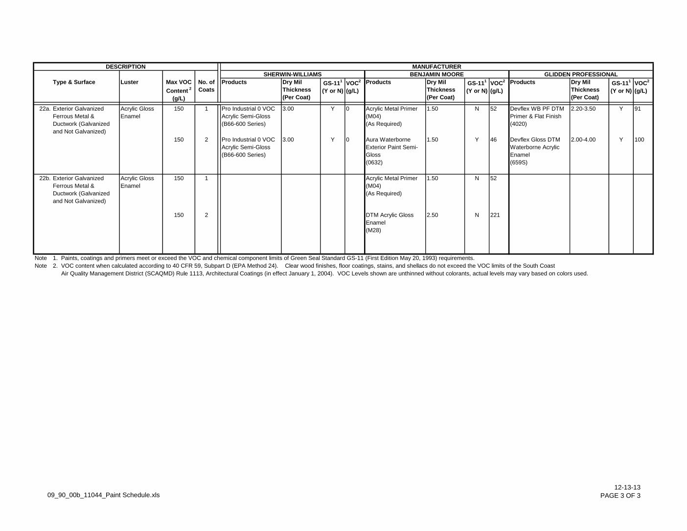
Type & Surface Luster Max VOC
Content 2
(g/L)
No. of
Coats
Products Dry Mil
Thickness
(Per Coat)
GS-111
(Y or N)
VOC2
(g/L)
Products Dry Mil
Thickness
(Per Coat)
GS-111
(Y or N)
VOC2
(g/L)
Products Dry Mil
Thickness
(Per Coat)
GS-111
(Y or N)
VOC2
(g/L)
BENJAMIN MOORE GLIDDEN PROFESSIONAL
MANUFACTURERDESCRIPTION
SHERWIN-WILLIAMS
22a. Exterior Galvanized
Ferrous Metal &
Ductwork (Galvanized
and Not Galvanized)
Acrylic Gloss
Enamel
150 1 Pro Industrial 0 VOC
Acrylic Semi-Gloss
(B66-600 Series)
3.00 Y 0 Acrylic Metal Primer
(M04)
(As Required)
1.50 N 52 Devflex WB PF DTM
Primer & Flat Finish
(4020)
2.20-3.50 Y 91
150 2 Pro Industrial 0 VOC
Acrylic Semi-Gloss
(B66-600 Series)
3.00 Y 0 Aura Waterborne
Exterior Paint Semi-
Gloss
(0632)
1.50 Y 46 Devflex Gloss DTM
Waterborne Acrylic
Enamel
(659S)
2.00-4.00 Y 100
22b. Exterior Galvanized
Ferrous Metal &
Ductwork (Galvanized
and Not Galvanized)
Acrylic Gloss
Enamel
150 1 Acrylic Metal Primer
(M04)
(As Required)
1.50 N 52
150 2 DTM Acrylic Gloss
Enamel
(M28)
2.50 N 221
Note 1. Paints, coatings and primers meet or exceed the VOC and chemical component limits of Green Seal Standard GS-11 (First Edition May 20, 1993) requirements.
Note 2. VOC content when calculated according to 40 CFR 59, Subpart D (EPA Method 24). Clear wood finishes, floor coatings, stains, and shellacs do not exceed the VOC limits of the South Coast
Air Quality Management District (SCAQMD) Rule 1113, Architectural Coatings (in effect January 1, 2004). VOC Levels shown are unthinned without colorants, actual levels may vary based on colors used.
09_90_00b_11044_Paint Schedule.xls12-13-13
PAGE 3 OF 3

11044 FIRE PROTECTION SPECIALTIES
10 44 00 - 1 12-13-13
SECTION 10 44 00
FIRE PROTECTION SPECIALTIES
PART 1 GENERAL
1.01 SUMMARY
A. Section Includes:
1. Fire Extinguishers and Brackets
2. Accessories
1.02 REFERENCES
A. NFPA 10 - Portable Fire Extinguishers
1.03 SUBMITTALS
A. General: Submit the following in accordance with Conditions of Contract and Division 01 Specification Sections:
1. Submit product data which shall include physical dimensions, operational features, color and finish, anchorage details, rough-in measurements, location, and details.
2. Submit manufacturer's installation instructions.
1.04 QUALITY ASSURANCE
A. National Fire Protection Association (NFPA) Publications:
1. NFPA 10 - Portable Fire Extinguishers
B. Underwriter's Laboratories, Inc. (UL) Standards:
1. UL 4A-60BC classification
1.05 OPERATION AND MAINTENANCE DATA
A. Do not install extinguishers when ambient temperatures may cause freezing.
PART 2 PRODUCTS
2.01 ACCEPTABLE MANUFACTURERS
A. Approved Manufacturers:
1. Larsen's Manufacturing Company (800-527-7367).
2. J. L. Industries, Inc. (800-554-6077).
3. Modern Metal Products, a Division of Technico, Inc. (800-435-5544)
2.02 EXTINGUISHERS:
A. Multi-Purpose, Dry-Chemical Type: Steel Tank, pressurized, including hose and nozzle; 10-pound, ABC classification, UL 4A/60BC.
2.03 BRACKET:
A. Furnish wall mount bracket where shown on Drawings complete with mounting hardware.
2.04 FINISHES
A. Extinguishers: Red Enamel
11044 FIRE PROTECTION SPECIALTIES
10 44 00 - 1 12-13-13
PART 3 EXECUTION
3.01 INSPECTION
A. Beginning of installation means acceptance of existing conditions.
3.02 INSTALLATION
A. Install extinguishers plumb and level with wall mount bracket. Secure rigidly in place in accordance with manufacturer's instructions.
END OF SECTION 10 44 00

11044
WATER SPRAYGROUND 13 11 00-1
12-13-13
SECTION 131100
WATER SPRAYGROUND
PART 1 - GENERAL
1.01 RELATED DOCUMENTS
A. Drawings and General Provisions of the Contract, including General and Supplementary Conditions and Division 1 - Specification Sections, apply to the work specified in this section.
1.02 SUMMARY
A. Furnish all labor, material, equipment and services for installation of the water sprayground including sprayground areas, water features, controllers, programming software and all sprayground system components.
B. The outdoor water sprayground shall have an approximate area of 7,367 square feet including the various water play features as indicated in these specifications as well as swimming pool drawings.
C. Design, furnish and install water pad structure and install final finishes to this surface.
D. Furnish and install the water sprayground systems as indicated on the swimming pool drawings, specified herein, and as necessary for proper completion including, but is not necessarily limited to:
1. All water spray features.
2. All activation devices.
3. All controllers.
4. Supply and installation of mechanical equipment and pool piping as necessary for sprayground operation.
5. Operations and maintenance manuals.
6. On site startup training.
7. Proper winterization of the sprayground system.
8. Proper signage as required.
E. Related Work Specified Elsewhere
1. All electrical works, buildings and permits.
1.03 QUALITY ASSURANCE
A. The supplier shall demonstrate their specific experience and competency in the manufacturing and installation of the water sprayground equipment and systems.
B. The supplier shall have completed at least five installations comparable to the system specified herein within the last 5 years. Submit a list of such projects with name, address and current telephone number of the Owner's Operator and Architect of Record to the Architect with bid on the bid date.
C. The Owner reserves the right to reject any bid if the evidence submitted by, or investigation of, such bidder fails to satisfy the Owner that such bidder is properly qualified to carry out the obligation of the contract and to complete work described or if bidder does not have the qualifications stated herein.
1.04 REGULATORY AGENCY REQUIREMENTS AND ENGINEERING SERVICES
A. The entire water sprayground system shall be designed and installed to meet all national and local codes and be in compliance with applicable sections of the American National Standards Institute / National Spa and Pool Institute (ANSI /NSPI-2 1999).
B. The system shall comply with all necessary approvals obtained by the Architect from local regulatory agencies governing the design and construction of public swimming pools.

11044
WATER SPRAYGROUND 13 11 00-2
12-13-13
C. The CONTRACTOR shall give all necessary notices, obtain all permits and pay all government fees, and other costs in connection with his work; file all necessary drawings, prepare all documents and obtain all necessary approvals of governmental departments having jurisdiction; obtain all required certificates of inspection for his work and deliver same to the Architect before request for acceptance and final payment for the work.
D. The CONTRACTOR shall include in the work, without extra cost to the Owner, any labor, materials, services, apparatus or drawings in order to comply with all applicable laws, ordinances, rules and regulations, whether or not shown on drawings and/or specified.
E. Where provisions of pertinent codes and standards conflict with this specification, the more stringent shall govern.
1.05 COORDINATION AND CLARIFICATION
A. Coordinate with other trades affecting and affected by work in this section.
B. The CONTRACTOR must establish with other contractors or subcontractors, having related work in this Section, that all work necessary to complete the sprayground as shown on the drawings and in the specifications is included in the base bid and alternates to the Owner.
C. If in doubt regarding the responsibility for work covered in this section and/or discovery of errors or omissions in the bidding documents, the CONTRACTOR shall notify the Architect through channels established by the specifications and request a clarification ten (10) days prior to the bid date.
1.06 CONTRACTORS ALTERNATIVE PROPOSAL
A. Suppliers to submit their bid based on materials, equipment and methods as specified in this section. Any substitutions of material, equipment or method must be submitted in accordance with the specified procedure described in Division 1. Any required changes to the construction documents shall be described in writing and any costs or changes must be included in the price quoted to complete the installation.
1.07 SUBMITTALS
A. Division 1 requirements.
B. Shop Drawings
1. Provide a complete set of checked shop drawings required to fabricate and assemble all water sprayground systems.
2. Statements
a. Furnish the Owner with copies of all permits and receipts for fee payments.
3. Test Reports
a. Submit a sample form of any performance test reports that will be used by the installer following the water sprayground erection, prior to beginning of installation.
C. Include complete product data indexed, tabbed and referenced to specifications.
D. Submit details indicated the water spray elements, activation devices, controllers, as well as any necessary flow regulation devices necessary to operate the water sprayground system as indicated by the manufacturer.
E. Specify water supply requirements and required pump characteristics to Architect, for approval, prior to preparation of fabrication drawings.
F. Guarantee / Warranty
1. All work of this section shall be warranted against all defects of material and/or application for a period of one (1) year from date of acceptance. Any failures that may occur within this warranty period, due to defective installation and/or materials, shall upon written notification of such failure be immediately repaired or replaced.
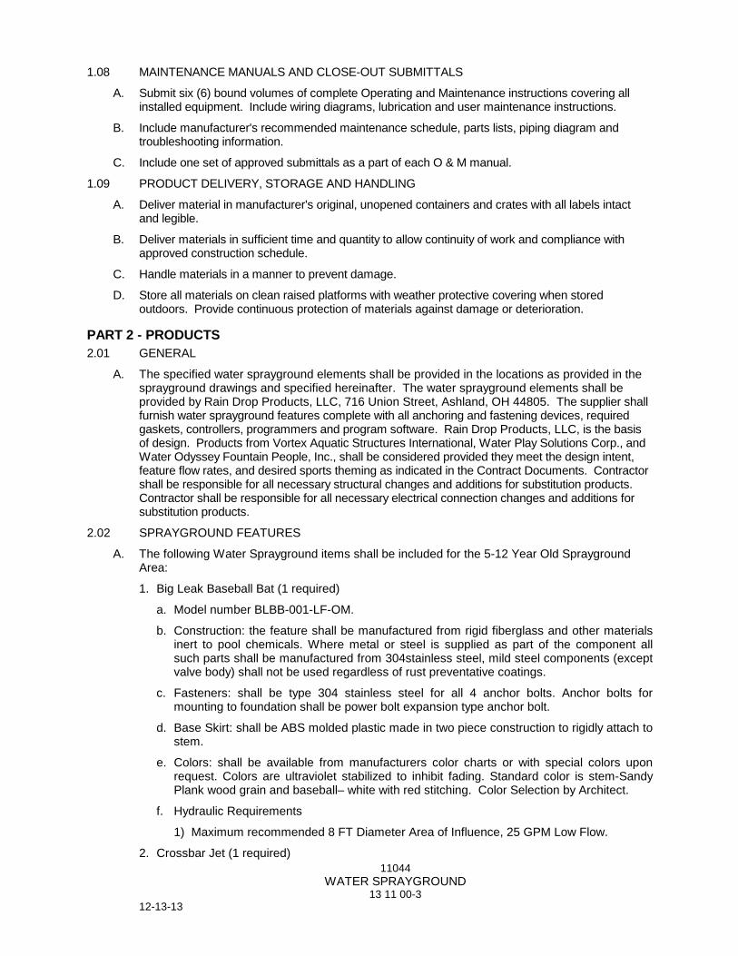
11044
WATER SPRAYGROUND 13 11 00-3
12-13-13
1.08 MAINTENANCE MANUALS AND CLOSE-OUT SUBMITTALS
A. Submit six (6) bound volumes of complete Operating and Maintenance instructions covering all installed equipment. Include wiring diagrams, lubrication and user maintenance instructions.
B. Include manufacturer's recommended maintenance schedule, parts lists, piping diagram and troubleshooting information.
C. Include one set of approved submittals as a part of each O & M manual.
1.09 PRODUCT DELIVERY, STORAGE AND HANDLING
A. Deliver material in manufacturer's original, unopened containers and crates with all labels intact and legible.
B. Deliver materials in sufficient time and quantity to allow continuity of work and compliance with approved construction schedule.
C. Handle materials in a manner to prevent damage.
D. Store all materials on clean raised platforms with weather protective covering when stored outdoors. Provide continuous protection of materials against damage or deterioration.
PART 2 - PRODUCTS
2.01 GENERAL
A. The specified water sprayground elements shall be provided in the locations as provided in the sprayground drawings and specified hereinafter. The water sprayground elements shall be provided by Rain Drop Products, LLC, 716 Union Street, Ashland, OH 44805. The supplier shall furnish water sprayground features complete with all anchoring and fastening devices, required gaskets, controllers, programmers and program software. Rain Drop Products, LLC, is the basis of design. Products from Vortex Aquatic Structures International, Water Play Solutions Corp., and Water Odyssey Fountain People, Inc., shall be considered provided they meet the design intent, feature flow rates, and desired sports theming as indicated in the Contract Documents. Contractor shall be responsible for all necessary structural changes and additions for substitution products. Contractor shall be responsible for all necessary electrical connection changes and additions for substitution products.
2.02 SPRAYGROUND FEATURES
A. The following Water Sprayground items shall be included for the 5-12 Year Old Sprayground Area:
1. Big Leak Baseball Bat (1 required)
a. Model number BLBB-001-LF-OM.
b. Construction: the feature shall be manufactured from rigid fiberglass and other materials inert to pool chemicals. Where metal or steel is supplied as part of the component all such parts shall be manufactured from 304stainless steel, mild steel components (except valve body) shall not be used regardless of rust preventative coatings.
c. Fasteners: shall be type 304 stainless steel for all 4 anchor bolts. Anchor bolts for mounting to foundation shall be power bolt expansion type anchor bolt.
d. Base Skirt: shall be ABS molded plastic made in two piece construction to rigidly attach to stem.
e. Colors: shall be available from manufacturers color charts or with special colors upon request. Colors are ultraviolet stabilized to inhibit fading. Standard color is stem-Sandy Plank wood grain and baseball– white with red stitching. Color Selection by Architect.
f. Hydraulic Requirements
1) Maximum recommended 8 FT Diameter Area of Influence, 25 GPM Low Flow.
2. Crossbar Jet (1 required)

11044
WATER SPRAYGROUND 13 11 00-4
12-13-13
a. Model number CBJT-008-LF-OM.
b. Construction: the feature shall be manufactured from rigid fiberglass and other materials inert to pool chemicals. Where metal or steel is supplied as part of the component all such parts shall be manufactured from 304stainless steel, mild steel components (except valve body) shall not be used regardless of rust preventative coatings.
c. Piping: and/or structural tubing shall be six inch rigid corrosion proof, fiberglass material with a smooth high gloss finish. Attachment flanges shall provide eight 3/4” bolt holes for mounting at the base of the pipe and/or structural tubing.
d. Fasteners: shall be type 304 stainless steel for all 4 anchor bolts. Anchor bolts for mounting to foundation shall be power bolt expansion type anchor bolt.
e. Base Skirt: shall be ABS molded plastic made in two piece construction to rigidly attach to stem.
f. Colors: shall be available from manufacturers color charts or with special colors upon request. Colors are ultraviolet stabilized to inhibit fading. Color Selection by Architect.
g. Hydraulic Requirements
1) Maximum recommended 11 FT (L) x 6 FT (W) Area of Influence, 25 GPM Low Flow.
3. T-Crossbar Spraying Goal Post (1 required)
a. Model number TCFG-001-LF-OM.
b. Construction: the feature shall be manufactured from rigid fiberglass and other materials inert to pool chemicals. Where metal or steel is supplied as part of the component all such parts shall be manufactured from 304stainless steel, mild steel components (except valve body) shall not be used regardless of rust preventative coatings.
c. Piping: and/or structural tubing shall be six inch rigid corrosion proof, fiberglass material with a smooth high gloss finish. Attachment flanges shall provide eight 3/4” bolt holes for mounting at the base of the pipe and/or structural tubing.
d. Fasteners: shall be type 304 stainless steel for all 4 anchor bolts. Anchor bolts for mounting to foundation shall be power bolt expansion type anchor bolt.
e. Base Skirt: shall be ABS molded plastic made in two piece construction to rigidly attach to stem.
f. Colors: shall be available from manufacturers color charts or with special colors upon request. Colors are ultraviolet stabilized to inhibit fading. Color Selection by Architect.
g. Hydraulic Requirements
1) Maximum recommended 11 FT (L) x 6 FT (W) Area of Influence, 25 GPM Low Flow.
4. Tennis Racquet Hoop (“Watery Racquet”) (1 required)
a. Model number TRHP-001-MF-OM.
b. Construction: the feature shall be manufactured from rigid fiberglass and other materials inert to pool chemicals. Where metal or steel is supplied as part of the component all such parts shall be manufactured from 304stainless steel, mild steel components (except valve body) shall not be used regardless of rust preventative coatings.
c. Piping: and/or structural tubing shall be six inch rigid corrosion proof, fiberglass material with a smooth high gloss finish.
d. Fasteners: shall be type 304 stainless steel for all 4 anchor bolts. Anchor bolts for mounting to foundation shall be power bolt expansion type anchor bolts.
e. Colors: shall be available from manufacturers color charts or with special colors upon request. Colors are ultraviolet stabilized to inhibit fading. Color Selection by Architect.

11044
WATER SPRAYGROUND 13 11 00-5
12-13-13
f. Hydraulic Requirements
1) Maximum recommended 9 FT (L) x 3 FT (W) Area of Influence, 1.9 GPM Low Flow.
5. Misting Soccer Ball (1 required)
a. Model number SCBL-001-MF-OM.
b. Construction: the feature shall 3’ FT 6” IN diameter and shall be manufactured from high density molded fiberglass suitable for installation in a swimming pool environment. Where metal or steel is supplied as part of the component all such parts shall be manufactured from 304 stainless steel, mild steel components shall not be used regardless of rust preventative coatings. Feature shall anchor flush on the surface to which they are installed and shall be capable of emitting multiple streams of water from nozzle mounted on top of feature.
c. Colors: shall be supplied in standard colors. Special colors are available upon request. Colors are ultraviolet stabilized to inhibit fading. Color Selection by Architect.
d. Hydraulic Requirements
1) Maximum recommended 5 FT Diameter Area of Influence, 1 GPM Low Flow.
6. Fielder’s Glove Misting Hoop (1 required)
a. Model number BLBG-001-MF-OM.
b. Construction: the feature shall be manufactured from rigid fiberglass and other materials inert to pool chemicals. Where metal or steel is supplied as part of the component all such parts shall be manufactured from 304stainless steel, mild steel components (except valve body) shall not be used regardless of rust preventative coatings.
c. Fasteners: shall be type 304 stainless steel for all 4 anchor bolts. Anchor bolts for mounting to foundation shall be power bolt expansion type anchor bolts.
d. Colors: shall be available from manufacturers color charts or with special colors upon request. Colors are ultraviolet stabilized to inhibit fading. Color Selection by Architect.
e. Hydraulic Requirements
1) Maximum recommended 6 FT (L) x 3 FT (W) Area of Influence, 2.5 GPM Low Flow.
7. Giant Circle Time (1 required)
a. Model number GICR-16-001-LF.
b. Construction: The body shall be manufactured from heavy duty, high tensile strength Schedule 80 PVC, gas welded and shall be impervious to rust and corrosion. The nozzles shall be high strength, corrosion resistant machine cast brass.
c. Piping/Stem: All piping connection shall be made from heavy-duty high tensile strength Schedule 80 PVC.
d. Hydraulic Requirements
1) Maximum recommended 18 FT Diameter Area of Influence, 18 GPM Low Flow.
8. Water Fun Cannon (2 required)
a. Model number WFCN-004-OM.
b. Construction: the feature shall be manufactured from rigid fiberglass and other materials inert to pool chemicals. Where metal or steel is supplied as part of the component all such parts shall be manufactured from 304stainless steel, mild steel components (except valve body) shall not be used regardless of rust preventative coatings.
c. Piping: and/or structural tubing shall be six inch rigid corrosion proof, fiberglass material with a smooth high gloss finish. Attachment flanges shall provide eight 3/4” bolt holes for mounting at the base of the pipe and/or structural tubing.
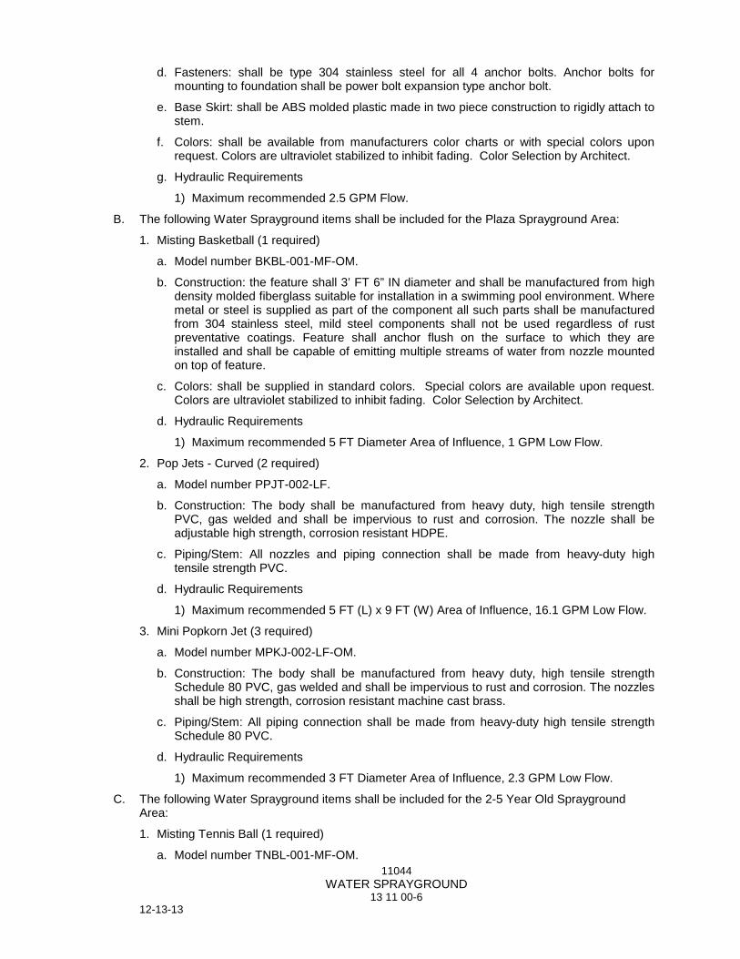
11044
WATER SPRAYGROUND 13 11 00-6
12-13-13
d. Fasteners: shall be type 304 stainless steel for all 4 anchor bolts. Anchor bolts for mounting to foundation shall be power bolt expansion type anchor bolt.
e. Base Skirt: shall be ABS molded plastic made in two piece construction to rigidly attach to stem.
f. Colors: shall be available from manufacturers color charts or with special colors upon request. Colors are ultraviolet stabilized to inhibit fading. Color Selection by Architect.
g. Hydraulic Requirements
1) Maximum recommended 2.5 GPM Flow.
B. The following Water Sprayground items shall be included for the Plaza Sprayground Area:
1. Misting Basketball (1 required)
a. Model number BKBL-001-MF-OM.
b. Construction: the feature shall 3’ FT 6” IN diameter and shall be manufactured from high density molded fiberglass suitable for installation in a swimming pool environment. Where metal or steel is supplied as part of the component all such parts shall be manufactured from 304 stainless steel, mild steel components shall not be used regardless of rust preventative coatings. Feature shall anchor flush on the surface to which they are installed and shall be capable of emitting multiple streams of water from nozzle mounted on top of feature.
c. Colors: shall be supplied in standard colors. Special colors are available upon request. Colors are ultraviolet stabilized to inhibit fading. Color Selection by Architect.
d. Hydraulic Requirements
1) Maximum recommended 5 FT Diameter Area of Influence, 1 GPM Low Flow.
2. Pop Jets - Curved (2 required)
a. Model number PPJT-002-LF.
b. Construction: The body shall be manufactured from heavy duty, high tensile strength PVC, gas welded and shall be impervious to rust and corrosion. The nozzle shall be adjustable high strength, corrosion resistant HDPE.
c. Piping/Stem: All nozzles and piping connection shall be made from heavy-duty high tensile strength PVC.
d. Hydraulic Requirements
1) Maximum recommended 5 FT (L) x 9 FT (W) Area of Influence, 16.1 GPM Low Flow.
3. Mini Popkorn Jet (3 required)
a. Model number MPKJ-002-LF-OM.
b. Construction: The body shall be manufactured from heavy duty, high tensile strength Schedule 80 PVC, gas welded and shall be impervious to rust and corrosion. The nozzles shall be high strength, corrosion resistant machine cast brass.
c. Piping/Stem: All piping connection shall be made from heavy-duty high tensile strength Schedule 80 PVC.
d. Hydraulic Requirements
1) Maximum recommended 3 FT Diameter Area of Influence, 2.3 GPM Low Flow.
C. The following Water Sprayground items shall be included for the 2-5 Year Old Sprayground Area:
1. Misting Tennis Ball (1 required)
a. Model number TNBL-001-MF-OM.
11044
WATER SPRAYGROUND 13 11 00-7
12-13-13
b. Construction: the feature shall 3’ FT 6” IN diameter and shall be manufactured from high density molded fiberglass suitable for installation in a swimming pool environment. Where metal or steel is supplied as part of the component all such parts shall be manufactured from 304 stainless steel, mild steel components shall not be used regardless of rust preventative coatings. Feature shall anchor flush on the surface to which they are installed and shall be capable of emitting multiple streams of water from nozzle mounted on top of feature.
c. Colors: shall be supplied in standard colors. Special colors are available upon request. Colors are ultraviolet stabilized to inhibit fading. Color Selection by Architect.
d. Hydraulic Requirements
1) Maximum recommended 5 FT Diameter Area of Influence, 1 GPM Low Flow.
2. Misting Baseball (1 required)
a. Model number MTBL-001-MF-OM.
b. Construction: the feature shall 3’ FT 6” IN diameter and shall be manufactured from high density molded fiberglass suitable for installation in a swimming pool environment. Where metal or steel is supplied as part of the component all such parts shall be manufactured from 304 stainless steel, mild steel components shall not be used regardless of rust preventative coatings. Feature shall anchor flush on the surface to which they are installed and shall be capable of emitting multiple streams of water from nozzle mounted on top of feature.
c. Colors: shall be supplied in standard colors. Special colors are available upon request. Colors are ultraviolet stabilized to inhibit fading. Color Selection by Architect.
d. Hydraulic Requirements
1) Maximum recommended 5 FT Diameter Area of Influence, 1 GPM Low Flow.
3. Aqua Run Slide (1 required)
a. Model number AQRN-001-LF-OM.
b. Construction: the feature shall be manufactured from molded fiberglass and other materials inert to pool chemicals. Where metal or steel is supplied as part of the component all such parts shall be manufactured from 304 stainless steel, mild steel components (except valve body) shall not be used regardless of rust preventive coatings.
c. Piping/Material: and/or structural tubing shall be rigid corrosion proof, reinforced fiberglass material with a smooth high gloss finish.
d. Fasteners: shall be type 304 stainless steel for all anchor bolts, fasteners and bolt ring. Anchor bolts for mounting to foundation shall be expansion type anchor bolts.
e. Colors: shall be available from manufacturers color charts or with special colors upon request. Colors are ultraviolet stabilized to inhibit fading. Slide run and steps to be standard Light House White. Color Selection by Architect.
f. Hydraulic Requirements
1) Maximum recommended 10 FT (L) x 12 FT (W) Area of Influence, 6.6 GPM Low Flow.
4. Slide Exit Pad – 3’ x 8’ (1 required)
a. Model number Pad-3X8.
b. Foam Pad: shall be 2" thick, durable closed cell foam.
c. Cover: shall be slip resistant, fully adhered, 60 ml. PVC liner membrane.
d. Fasteners: shall be stainless steel anchor fasteners. Nylon bantum plug inserts are supplied for conductor isolation.

11044
WATER SPRAYGROUND 13 11 00-8
12-13-13
e. Colors: to be standard light blue. (Pebble)
5. Tunnel Arch (1 required)
a. Model number TNAR-008.
b. Construction: The body shall be manufactured from heavy duty, high tensile strength PVC, gas welded and shall be impervious to rust and corrosion. The nozzle shall be adjustable high strength, corrosion resistant HDPE.
c. Piping/Stem: All piping connection shall be made from heavy-duty high tensile strength PVC.
d. Hydraulic Requirements
1) Maximum recommended 8 FT (L) x 6 FT (W) Area of Influence, 30 GPM Flow.
6. Mini Foam Geyser (2 required)
a. Model number FMGS-002-OM.
b. Construction: The body shall be manufactured from heavy duty, high tensile strength Schedule 80 PVC, gas welded and shall be impervious to rust and corrosion. The nozzles shall be high strength, corrosion resistant HDPE.
c. Piping/Stem: All piping connection shall be made from heavy-duty high tensile strength Schedule 80 PVC.
d. Hydraulic Requirements
1) Maximum recommended 5 FT Diameter Area of Influence, 5 GPM Flow.
7. Mini Popkorn Jet (3 required)
a. Model number MPKJ-002-LF-OM.
b. Construction: The body shall be manufactured from heavy duty, high tensile strength Schedule 80 PVC, gas welded and shall be impervious to rust and corrosion. The nozzles shall be high strength, corrosion resistant machine cast brass.
c. Piping/Stem: All piping connection shall be made from heavy-duty high tensile strength Schedule 80 PVC.
d. Hydraulic Requirements
1) Maximum recommended 3 FT Diameter Area of Influence, 2.3 GPM Low Flow.
8. Upstream Jet (4 required)
a. Model number UPJT-007-LF-OM.
b. Construction: The body shall be manufactured from heavy duty, high tensile strength Schedule 80 PVC, gas welded and shall be impervious to rust and corrosion. The nozzles shall be high strength, corrosion resistant HDPE.
c. Piping/Stem: All piping connection shall be made from heavy-duty high tensile strength Schedule 80 PVC.
d. Colors: Cover to be standard white with blue ball nozzle.
e. Hydraulic Requirements
1) Maximum recommended 3 FT Diameter Area of Influence, 2.3 GPM Low Flow.
9. Slant Jet (4 required)
a. Model number SLJT-003-LF-OM.
b. Construction: The body shall be manufactured from heavy duty, high tensile strength PVC, gas welded and shall be impervious to rust and corrosion. The nozzle shall be adjustable high strength, corrosion resistant HDPE.

11044
WATER SPRAYGROUND 13 11 00-9
12-13-13
c. Piping/Stem: All piping connection shall be made from heavy-duty high tensile strength PVC.
d. Hydraulic Requirements
1) Maximum recommended 8 FT (L) x 4 FT (W) Area of Influence, 1.2 GPM Low Flow.
2.03 SPRAYGROUND FEATURES MOUNTING SYSTEM
A. Omni-Pod (29 required)
1. Model number POD-A001
2. Construction: The body shall be manufactured from heavy wall PVC and shall be impervious to rust and corrosion. The top plate/cover shall be white high strength PVC, .250 inch thick. The plate shall be installed with a removable tamper resistant screw. Cover can be removed when a feature is ready to be installed. The cover can be replaced to cover the supply inlet if the feature is removed at any time. The tamper resistant screws must be stainless steel to prevent corrosion.
3. Piping/Stem: All piping connection shall be made from heavy-duty high tensile strength PVC. A female socket weld connection shall be supplied to connect to the water supply line supplied by others.
4. Colors: Cover to be standard white. Body to be standard gray.
2.04 SPRAYGROUND DRAINS
A. 12” x 12” Drain Box with 6” Outlet (3 required)
1. Model number DRN12-002.
2. Construction: the drain shall be manufactured from rigid fiberglass with a gel-coat interior and other materials inert to pool chemicals. Where metal or steel is supplied as part of the feature all such parts shall be either 304 stainless steel, brass or corrosion protected.
3. Colors: shall be white grate with industrial gray sump.
4. Hydraulic Requirements
a. Maximum recommended drain capacity of 135 GPM at 1.5 FT/S.
2.05 SPRAYGROUND ACTIVATION BOLLARDS
A. Activation Bollard (3 required)
1. Model number BOL-A001.
2. GENERAL
a. The specified feature shall be suitable for installation in spraygrounds and shall be manufactured by Rain Drop Products. The supplier shall furnish bollard complete with all anchoring and fastening devices, required gaskets and base skirt. Installation shall be supplied by others. Rain Drop Products, LLC, is the basis of design. Products from Vortex Aquatic Structures International, Water Play Solutions Corp., and Water Odyssey Fountain People, Inc., shall be considered provided they meet the design intent, feature flow rates, and desired sports theming as indicated in the Contract Documents. Contractor shall be responsible for all necessary structural changes and additions for substitution products. Contractor shall be responsible for all necessary electrical connection changes and additions for substitution products.
3. DESIGN
a. Construction: the feature shall be manufactured from rigid fiberglass and other materials inert to pool chemicals. Where metal or steel is supplied as part of the feature all such parts shall be either 304 stainless steel, brass or corrosion protected.

11044
WATER SPRAYGROUND 13 11 00-10
12-13-13
b. Piping/Stem: shall be rigid corrosion proof and shall consist of an 8-inch diameter, rigid fiberglass bollard with a high gloss finish housing an infrared sensor. Attachment flange shall provide 3/4 inch bolt holes on a 11.5 inch bolt pattern. PVC is not acceptable and shall not be used.
c. Structural Piping Strength:
1) Tensile Strength (Longitudinal) = 110,000 psi; Compressive Strength (Longitudinal) = 50,000 psi; Compressive Strength (Circumferential) = 26,000 psi.
d. Fasteners: shall be type 304 stainless steel for all anchor bolts, fasteners, and bolt ring. Anchor bolts for mounting to foundation shall be expansion type anchor bolts.
e. Base Skirt: shall be ABS molded plastic made in two piece construction to rigidly attach to stem.
f. Colors: shall be available from manufacturers color charts or with special colors upon request. Colors are ultraviolet stabilized to inhibit fading.
4. CONTROLS
a. Activator: The Activator is an infrared sensor protected by a lexan face plate. The sensor senses the presence of a person and sends a signal to the CPU to activate the systems software program. The program stays on for approximately 12 minutes before it needs to be re-activated.
b. Wiring: Bollard Activator operates on 24 VAC current and is hard wired to the CPU. It is designed to turn off when the program is not reactivated by movement on the Sprayground. The sensor has a safety override built into it to prevent an individual from trying to bypass it by covering it with an object in order to keep the Sprayground CPU running constantly.
5. FEATURE/FLOW OPTIONS
a. Sku # BOL-A001: Standard Bollard Activator feature with a gasket. Gasket shall be 1/4 inch thick 40 durameter neoprene rubber.
2.06 SPRAYGROUND CONTROL SYSTEM
A. Rain Brain Control System (1 required) – 32 Solenoid Outputs with Expansion Capability
1. General
a. Rain Drop Products, LLC, is the basis of design. Products from Vortex Aquatic Structures International, Water Play Solutions Corp., and Water Odyssey Fountain People, Inc., shall be considered provided they meet the design intent, feature flow rates, and desired sports theming as indicated in the Contract Documents. Contractor shall be responsible for all necessary structural changes and additions for substitution products. Contractor shall be responsible for all necessary electrical connection changes and additions for substitution products.
b. The control system shall be comprised of a PC, 10.1” color touch screen, I/O Modbus interface, and/or Can bus interface, operating on a Linux operating platform. The controllers’ primary function is to control the operation of pumps, solenoids, sound, lighting features, and monitoring the water quality of a water play facility. The master control shall have remote access and control capability with Ethernet or wireless communication.
2. Design
a. Construction: The controllers’ enclosure shall be a NEMA 4 fiberglass enclosure for indoor and outdoor application. The enclosure shall have hinged door with latches that can be padlocked. Enclosure sizes vary depending on the number and type of outputs. The master control shall have a 10.1” touch screen to program and monitor the slave controls. All electrical ports entering and exiting the enclosure shall be water tight plug

11044
WATER SPRAYGROUND 13 11 00-11
12-13-13
connectors, and have a screw cap when not in use. All electrical devices and components shall be compliant with one or more of the following; UL, CE, CSA, RoHS, and the FCC.
b. Power Requirements: 120 Volts, 20 Amps
c. Interface: The user interface on the master control shall be a 10.1” color touch screen. The resolution shall be 1024x600.
d. Input and Output device: Control shall communicate with devices utilizing a Modbus and/or Can Bus to controlled device. There shall be no less than (32) I/O ports and shall operate on 24VDC. The control shall have no less than (2) RS-232 Serial ports, (2) USB ports, (1) PS/2 connections for external mouse and keyboard, (1) VGA.
e. Fail Safe: The CPU shall monitor and shut down the system in the event one or more pumps devices alarm or fail. The control shall send a trouble alert in an email or other specified method.
f. Environmental: Operating temperature range shall be between 0°C to 45ºC, and 30% to 90% relative humidity (non-condensing)
g. Memory: Shall have not less than 80GB HDD, 1GB DDR2.
h. Other features: No fan design, Auto power on after power failure, wireless ready, Boot from LAN.
3. Warranty
a. Limited Warranty shall be furnished by manufacturer against defects in workmanship and materials for a period of one year from date of commissioning by Rain Drop Products factory representative.
B. 4” Manifold (2 required) – One (1) Manifold to have eighteen (18) solenoid valve assembly and one (1) Manifold to have seventeen (17) solenoid valve assembly.
1. GENERAL
a. The Flow Control Manifold System shall be responsible for controlling, and distributing the water to the water features on the Sprayground or in the pool.
2. DESIGN
a. Construction: The Flow Control Manifold System shall be constructed of high strength Schedule 80 PVC. The manifold system shall incorporate distribution nipples constructed of Schedule 80 PVC gas welded to the main manifold body. No connection tees are allowed. No solvent (glue) welding is permissible.
b. Sizes: shall be available in four inch based on the amount of water flow as indicated on the Sprayground layout.
3. CONTROLS
a. Ball Valves: Each outlet shall contain a PVC ball valve on outlets 2” and smaller (butterfly valves shall be supplied by contractor for larger sizes) to adjust the flow of water from the main manifold body.
b. Solenoid Valves: Each outlet as required shall incorporate an electrically operated valve for controlling the flow of water. The solenoid valve will either turn the water flow completely on or off. The valves shall be normally closed design and activated by a signal from the CPU.
c. Proportional Valves: Each outlet as required shall incorporate an electrically operated valve for controlling the flow of water. The proportional valve can control the flow of the water to varying degrees of flow. The valves shall be normally closed design and activated by a signal from the CPU.
d. Outlets: The outlets shall be designed so that the valves can be removed from the main body of the manifold by disconnecting a union. They shall not be permanently attached. A
11044
WATER SPRAYGROUND 13 11 00-12
12-13-13
Van Stone Flange w/ swivel shall be attached to the inlet of the Manifold to allow for ease of attachment to the feature supply pump. The maximum number of outlets on a manifold is 20.
e. Testing: The entire manifold assembly shall be pressure tested to 150 PSI for 30 minutes with zero leakage.
2.07 PIPING SYSTEMS
A. General
1. Provide all piping between the sprayground and mechanical room, low voltage conduits, and all interconnecting piping to and from the sprayground controller system.
2. Provide all necessary pipe supports and support systems required to support all associated piping and valves.
3. Provide all other tubing, conduit, or piping associated with equipment specified herein. Coordinate with other trades.
B. Pipes
Pipe routing as shown and detailed on the Contract Drawings is diagrammatic unless otherwise noted and is not intended to show minor details or exact locations of piping systems. Installation is required to be adjusted to accommodate interference and adjustments anticipated and encountered. Pipe sizes on plans refer to nominal inside diameter of the pipe.
1. All sprayground piping and fittings shall be NSF approved, Schedule 80 PVC.
2. Connections between metallic piping and/or equipment and PVC shall be flanged. Molded fittings shall be as manufactured by Asahi, Eslon, Chemtrol, Spears, or acceptable substitute. Fabricated fittings shall be as manufactured by Harrison Machine, Plastinetics, or acceptable substitute.
3. All materials shall be installed by workmen thoroughly skilled in their trades and all work shall present a neat and mechanical appearance when complete. The CONTRACTOR, at no additional expense to the owner, shall replace or correct any work not judged acceptable by the architect, owner’s testing agency, or their consultants.
4. All support hardware, brackets, fasteners, hangers, etc. shall be stainless steel.
5. No installation shall be made that will provide a cross-connection or inter-connection between a distributing supply for drinking purposes and the sprayground, or between the sprayground and a sanitary or storm water sewer system that will permit a backflow of water into the sprayground water system.
6. All piping shall be hydrostatically (water) pressure tested for leaks before and after backfilling to guarantee water tightness. Pneumatic (air) pressure test not allowed.
7. Provisions shall be made to purge all pipes in the system.
C. Pipe Hangers and Supports
1. Manufacturer: Subject to compliance with these specifications, pipe hanger and support systems shall be manufactured by Cooper B-line (Basis of Design), Inc., TOLCO, and Anvil International or approved equal.
2. Hangers
a. Pipes 2 inch and smaller:
1) Adjustable steel clevis hanger, B-Line Models B3100 or B3104.
2) Adjustable steel swivel ring (band type) hanger, B-Line Model B3170
b. Pipes 2-1/2 and larger:
1) Adjustable steel clevis hanger, B-Line Model B3100.

11044
WATER SPRAYGROUND 13 11 00-13
12-13-13
3. Wall Supports
a. Pipes 2-1/2 inch and smaller:
1) Steel Offset J-Hook hanger, B-Line Model B3600
b. Pipes 3 inch and larger:
1) Welded strut bracket and pipe straps, B-line Models B3064 and B2000 Series.
4. Supplementary Structural Supports - Design and fabricate supports using structural quality steel bolted framing materials. Channels shall be roll formed, 12 gauge ASTM A1011 SS Grade 33 steel, 1-5/8 inch or greater as required by loading conditions. Submit design for pipe tunnels, pipe galleries etc. to engineer for approval. Use clamps and fittings designed for use with the strut system.
D. Hanger Attachments
1. Upper Attachments
a. Beam Clamps
1) Beam clamps shall be used where piping is to be suspended from building steel. Clamp type shall be selected on the basis of load to be supported, and load configuration.
2) C-Clamps shall be locknuts and cup point set screws similar to B-Line Model B351L or B3036L. Top flange c-clamps shall be used when attaching a hanger rod to the flange of structural steel, B-Line Model B3034 or B3033 or equal. Refer to manufacturers recommendations for setscrew torque. Retaining straps shall be used to maintain the clamp position on the beam where required.
3) Center load beam clamps shall be used where specified. Steel clamps shall be B-Line Models B3050 or B3055. Forged steel beam clamps with cross bolt shall be B-Line B3291-B3297 Series or equal as required to fit beams.
E. Hanger Accessories
1. Hanger Rods shall be threaded both ends or continuous threaded rod f circular cross section. Use adjustable locknuts at upper attachments and hangers. No wire, chain, or perforated straps are allowed.
F. Hanger Finish
1. Finishes:
a. Hangers and strut located in corrosive areas shall be type 316L stainless steel with stainless steel hardware.
G. Valves
1. Valves 3 inch and larger shall be butterfly type valves, with PVC body, 175# SWP with stainless steel shaft, polypropylene disc and replaceable resilient seat bonded to a rigid shaft and guaranteed for bubble tight shutoff from 27 inch vacuum to 150 PSI. Extended neck 2 inch beyond flanges for any insulated piping shall be provided with handle for manual operation. Valves to be Asahi/America, Chemtrol, George Fisher (G.F.), Bray or Dominion or acceptable substitute.
2. Valves smaller than 3" shall be PVC true union ball valves, full port, three-piece construction, blowout-proof stem, Viton seal with socket end connectors.
H. Pipe and valve identification
All exposed sprayground piping shall be equipped with color coded flow directional arrows at thirty (30) inch intervals. The following table shall be used to indicate the sprayground pipe color selection. The Contractor shall verify that all sprayground piping identification is in accordance with all local and state health regulations.

11044
WATER SPRAYGROUND 13 11 00-14
12-13-13
Pipe Service Application Color
Fresh Water Lines DARK BLUE
Main Drain Lines BLACK
All valves shall be identified with minimum 1-1/2 inch diameter brass tags stamped with minimum 1/2-inch high numbers and attached to valves with #16 brass jack chain. (Plastic laminate engraved tags with nylon attachment acceptable.) Valves shall be described as to their function and referenced in the operating instruction manual and wall mounted piping diagram to be prepared by the CONTRACTOR.
I. Testing
All piping installation and pressure testing shall be reviewed by the Owner’s testing agency before commencement of backfilling. A minimum of one week’s notice is required prior to review. Results of review shall be documented.
1. All sprayground related piping, shall be hydraulically pressure tested (with water, not air) to a pressure of not less than 50 PSI for a period of no less than two (2) hours.
2. Contractor is responsible for the maintenance of a sustained 20 PSI pressure on all sprayground related piping throughout the course of construction.
2.08 MAINTENANCE EQUIPMENT
The following items are to be supplied by the CONTRACTOR unless otherwise noted. All proprietary names are to designate performance only. Approved equal products will be accepted.
A. Heavy Duty Outdoor Brush (1 required) - Brush to be made with sturdy Durene plastic center and softer border bristle construction and designed for wet outdoor concrete areas. Brush shall have a natural hardwood block with two threaded handle holes. Brush shall be a minimum of 30” wide and to include a 5’ wood pole handle. Brush shall be supplied by Lincoln catalog # 32-067, or approved equal.
PART 3 - EXECUTION
3.01 SYSTEMS INSTALLATION
A. The water sprayground installer shall assemble and install all equipment, special parts and accessories in accordance with these specifications and detailed layouts and shop drawings of equipment supplier.
B. Installer shall furnish and install all anchors and inserts to be imbedded including all fittings, inserts, structure sleeves and required anchorages.
C. Install all equipment and systems in accordance with manufacturer's directions.
D. The water sprayground shall be as described in the specifications. Items are detailed and specified as a guide reference and for dimensional purposes. The Contractor must make provisions accordingly and submit shop drawings and submittals based on that data.
E. Installer shall coordinate, supervise and approve work by other trades responsible for work related to this section. All work in this section shall be performed by the water sprayground installer except as noted.
3.02 SITE CONDITIONS
A. Inspection
1. Prior to installation of the work of this section, carefully inspect the installed work of other trades and verify that all such work is complete to the point where this installation may properly commence.
2. Verify that all sprayground water spray features may be fabricated and erected in strict accordance with the original design, the approved shop drawings and the referenced standards.

11044
WATER SPRAYGROUND 13 11 00-15
12-13-13
B. Discrepancies
1. In the event of discrepancy, immediately notify the Architect.
2. Do not proceed with fabrication or installation in areas of discrepancy until all such discrepancies are fully resolved.
3.03 FABRICATION
A. Fabricate the water sprayground and its related systems in strict accordance with the approved shop drawings and referenced standards.
3.04 CLEAN-UP
A. Upon completion of the work of this section, immediately remove all fiberglass, debris and rubbish occasioned by this work to the approval of the Architect and at no additional cost to the Owner.
3.05 START-UP AND INSTRUCTION
A. Supply the services of an experienced operator/instructor to assist in the initial start-up and training of the water sprayground and its related systems has been completed and initially placed in operation. During this period, the Owner's representatives who will be operating the pool shall be thoroughly instructed in all phases of the water sprayground operation. Prior to leaving the job, obtain written certification from the designated Owner's representative acknowledging that the instruction period has been completed and all necessary operating information provided. A minimum of one (1) 2-hour session is required. Manufacturer of sprayground equipment shall have an on site representative for the commissioning of the water sprayground.
3.06 WINTERIZATION
A. The Contractor shall be responsible for assisting the Owner in the proper winterization methods for the water sprayground and its related equipment. Winterization equipment shall include Winterization plates that are manufactured to a minimum of 1/8” thickness, type 304 stainless steel plate with replacement gasket or O-ring and tamper resistant stainless steel screws. Winterization instructions shall also be included with the Operation & Maintenance manual.
3.07 WARRANTY
A. Shall be furnished by manufacturer providing a five year unconditional warranty against all defects in workmanship, materials and equipment operations for a period of one year from system start-up.
3.08 INSTALLATION
A. Drawings and instructions shall be supplied by manufacturer for ease of installation. Manufacturer shall supply a service technician to be on site at the time of system startup to ensure spray patterns are correct, lines are free and clear, water pressures are correct, the dynamic control module is programmed correctly, play events are correct and facility staff is properly trained on the operations of the dynamic module controller.
3.09 CONCLUSION
A. It is the intention of these specifications to provide a complete installation of the water spray ground as described. All accessory construction and apparatus necessary or advantageous in the operation or testing or high performance of the work shall be included. The omission of specific reference to any part of the work necessary for such complete installation shall not be interpreted as relieving the water spray ground supplier or installer from furnishing and installing such parts. Any such omission or clarification shall be brought to the attention of the Architect prior to bidding.
END OF SECTION 131100
11044
SITE CLEARING 31 10 00 - 1
12-13-13
SECTION 31 10 00
SITE CLEARING
PART 1 GENERAL
1.01 RELATED DOCUMENTS
A. Drawings and general provisions of the Contract, including General and Supplementary Conditions and Division 01 Specification Sections, apply to this Section.
1.02 SUMMARY
A. This Section includes the following:
1. Protecting existing trees, shrubs, groundcovers, plants, and grass to remain.
2. Removing existing trees, shrubs, groundcovers, plants, and grass.
3. Clearing and grubbing.
4. Stripping and stockpiling topsoil.
5. Removing above- and below-grade site improvements.
6. Disconnecting, capping or sealing, and removing site utilities.
7. Temporary erosion and sedimentation control measures.
B. Related Sections include the following:
1. Division 01 Section "Temporary Facilities and Controls" for temporary utilities, temporary construction and support facilities, temporary security and protection facilities, and temporary erosion and sedimentation control procedures.
2. Division 01 Section "Execution" for verifying utility locations and for recording field measurements.
3. Division 02 Section "Selective Structure Demolition" for partial demolition of buildings or structures undergoing alterations.
4. Division 31 Section "Earth Moving" for soil materials, excavating, backfilling, and site grading.
5. Division 32 Sections "Turf and Grasses” and “Plants” for finish grading including preparing and placing planting soil mixes and testing of topsoil material.
1.03 DEFINITIONS
A. Topsoil: Natural or cultivated surface-soil layer containing organic matter and sand, silt, and clay particles; friable, pervious, and black or a darker shade of brown, gray, or red than underlying subsoil; reasonably free of subsoil, clay lumps, gravel, and other objects more than 2 inches in diameter; and free of subsoil and weeds, roots, toxic materials, or other non-soil materials.
B. Tree Protection Zone: Area surrounding individual trees or groups of trees to be protected during construction, and defined by the drip line of individual trees or the perimeter drip line of groups of trees, unless otherwise indicated.
1.04 MATERIAL OWNERSHIP
A. Except for stripped topsoil or other materials indicated to remain Owner's property, cleared materials shall become Contractor's property and shall be removed from Project site.
1.05 SUBMITTALS
A. Photographs or videotape, sufficiently detailed, of existing conditions of trees and plantings, adjoining construction, and site improvements that might be misconstrued as damage caused by site clearing.
B. Record drawings, according to Division 01 Section "Project Record Documents," identifying and accurately locating capped utilities and other subsurface structural, electrical, and mechanical conditions.

11044
SITE CLEARING 31 10 00 - 2
12-13-13
1.06 QUALITY ASSURANCE
A. Preinstallation Conference: Conduct conference at Project site to comply with requirements in Division 01 Section "Project Management and Coordination."
1.07 PROJECT CONDITIONS
A. Traffic: Minimize interference with adjoining roads, streets, walks, and other adjacent occupied or used facilities during site-clearing operations.
1. Do not close or obstruct streets, walks, or other adjacent occupied or used facilities without permission from Owner and authorities having jurisdiction.
2. Provide alternate routes around closed or obstructed traffic ways if required by authorities having jurisdiction.
B. Improvements on Adjoining Property: Authority for performing site clearing indicated on property adjoining Owner's property will be obtained by Owner before award of Contract.
1. Do not proceed with work on adjoining property until directed by Architect.
C. Salvable Improvements: Carefully remove items indicated to be salvaged and store on Owner's premises where indicated.
D. Utility Locator Service: Notify utility locator service for area where Project is located before site clearing.
E. Do not commence site clearing operations until temporary erosion and sedimentation control measures are in place.
PART 2 PRODUCTS
2.01 SOIL MATERIALS
A. Satisfactory Soil Materials: Requirements for satisfactory soil materials are specified in Division 31 Section "Earth Moving."
1. Obtain approved borrow soil materials off-site when satisfactory soil materials are not available on-site.
PART 3 EXECUTION
3.01 PREPARATION
A. Protect and maintain benchmarks and survey control points from disturbance during construction.
B. Locate and clearly flag trees and vegetation to remain or to be relocated.
C. Protect existing site improvements to remain from damage during construction.
1. Restore, repair or replace damaged improvements to their original condition, as acceptable to Owner.
3.02 TEMPORARY EROSION AND SEDIMENTATION CONTROL
A. Provide temporary erosion and sedimentation control measures to prevent soil erosion and discharge of soil-bearing water runoff or airborne dust to adjacent properties and walkways, according to requirements of authorities having jurisdiction and sediment and erosion control Drawings.
B. Inspect, repair, and maintain erosion and sedimentation control measures during construction until permanent vegetation has been established.
C. Remove erosion and sedimentation controls and restore and stabilize areas disturbed during removal.
3.03 TREE PROTECTION
A. Erect and maintain temporary fencing around tree protection zones before starting site clearing. Remove fence when construction is complete.
1. Do not store construction materials, debris, or excavated material within fenced area.
2. Do not permit vehicles, equipment, or foot traffic within fenced area.
3. Maintain fenced area free of weeds and trash.

11044
SITE CLEARING 31 10 00 - 3
12-13-13
B. Do not excavate within tree protection zones, unless otherwise indicated.
C. Where excavation for new construction is required within tree protection zones, hand clear and excavate to minimize damage to root systems. Use narrow-tine spading forks, comb soil to expose roots, and cleanly cut roots as close to excavation as possible.
1. Cover exposed roots with burlap and water regularly.
2. Temporarily support and protect roots from damage until they are permanently redirected and covered with soil.
3. Coat cut faces of roots more than 1-1/2 inches in diameter with an emulsified asphalt or other approved coating formulated for use on damaged plant tissues.
4. Backfill with soil as soon as possible.
D. Repair or replace trees and vegetation indicated to remain that are damaged by construction operations, in a manner approved by Landscape Architect.
1. Employ an arborist, licensed in jurisdiction where Project is located, to submit details of proposed repairs and to repair damage to trees and shrubs.
2. Replace trees that cannot be repaired and restored to full-growth status, as determined by Landscape Architect.
3.04 UTILITIES
A. Locate, identify, disconnect, and seal or cap off utilities indicated to be removed.
1. Arrange with utility companies to shut off indicated utilities.
B. Existing Utilities: Do not interrupt utilities serving facilities occupied by Owner or others unless permitted under the following conditions and then only after arranging to provide temporary utility services according to requirements indicated:
1. Notify Architect not less than two days in advance of proposed utility interruptions.
2. Do not proceed with utility interruptions without Architect's written permission.
C. Excavate for and remove underground utilities indicated to be removed.
D. Removal of underground utilities is included in Division 22 and Division 33 Sections covering site utilities.
3.05 CLEARING AND GRUBBING
A. Remove obstructions, trees, shrubs, grass, and other vegetation to permit installation of new construction.
1. Do not remove trees, shrubs, and other vegetation indicated to remain or to be relocated.
2. Cut minor roots and branches of trees indicated to remain in a clean and careful manner where such roots and branches obstruct installation of new construction.
3. Grind stumps and remove roots, obstructions, and debris extending to a depth of 24 inches below exposed subgrade.
4. Use only hand methods for grubbing within tree protection zone.
5. Chip removed tree branches and dispose of off-site.
B. Fill depressions caused by clearing and grubbing operations with satisfactory soil material unless further excavation or earthwork is indicated.
1. Place fill material in horizontal layers not exceeding a loose depth of 8 inches, and compact each layer to a density equal to adjacent original ground.
3.06 TOPSOIL STRIPPING
A. Remove sod and grass before stripping topsoil.
B. Strip topsoil to whatever depths are encountered in a manner to prevent intermingling with underlying subsoil or other waste materials.
1. Remove subsoil and non-soil materials from topsoil, including trash, debris, weeds, roots, and other waste materials.

11044
SITE CLEARING 31 10 00 - 4
12-13-13
C. Stockpile topsoil materials away from edge of excavations without intermixing with subsoil. Grade and shape stockpiles to drain surface water. Cover to prevent windblown dust.
1. Limit height of topsoil stockpiles to 72 inches.
2. Do not stockpile topsoil within tree protection zones.
3. Dispose of excess topsoil as specified for waste material disposal.
4. Stockpile surplus topsoil to allow for respreading deeper topsoil.
3.07 SITE IMPROVEMENTS
A. Remove existing above- and below-grade improvements as indicated and as necessary to facilitate new construction.
B. Remove slabs, paving, curbs, gutters, and aggregate base as indicated.
1. Unless existing full-depth joints coincide with line of demolition, neatly saw-cut length of existing pavement to remain before removing existing pavement. Saw-cut faces vertically.
2. Paint cut ends of steel reinforcement in concrete to remain to prevent corrosion.
3.08 DISPOSAL
A. Disposal: Remove surplus soil material, unsuitable topsoil, obstructions, demolished materials, and waste materials including trash and debris, and legally dispose of them off Owner's property.
1. Separate recyclable materials produced during site clearing from other non-recyclable materials. Store or stockpile without intermixing with other materials and transport them to recycling facilities.
END OF SECTION 31 10 00
11044
EARTH MOVING 31 20 00 - 1
12-13-13
SECTION 31 20 00
EARTH MOVING
PART 1 GENERAL
1.01 RELATED DOCUMENTS
A. Drawings and general provisions of the Contract, including General and Supplementary Conditions and Division 01 Specification Sections, apply to this Section.
1.02 SUMMARY
A. Section Includes:
1. Preparing subgrades for slabs-on-grade, walks and turf and grasses.
2. Excavating and backfilling for buildings and structures.
3. Drainage course for concrete slabs-on-grade.
4. Subbase course for concrete walks and pavements.
5. Subbase and base course for asphalt paving.
6. Subsurface drainage backfill for walls and trenches.
7. Excavating and backfilling for utility trenches.
8. Excavating and backfilling trenches for utilities and pits for buried utility structures.
B. Related Sections:
1. Division 01 Section "Temporary Facilities and Controls" for temporary controls, utilities, and support facilities; also for temporary site fencing if not in another Section.
2. Divisions 21, 22, 23, 26, 27, 28, and 33 Sections for installing underground mechanical and electrical utilities and buried mechanical and electrical structures.
3. Division 31 Section "Site Clearing" for temporary erosion and sedimentation control measures site stripping, grubbing, stripping and stockpiling topsoil, and removal of above- and below-grade improvements and utilities.
4. Division 32 Section "Turf and Grasses" for finish grading, including preparing and placing planting soil for turf areas.
5. Division 32 Section “Plants” for tree pit excavation and planting.
6. Division 33 Section "Subdrainage" for drainage of landscape areas.
1.03 DEFINITIONS
A. Backfill: Soil material or controlled low-strength material used to fill an excavation.
1. Initial Backfill: Backfill placed beside and over pipe in a trench, including haunches to support sides of pipe.
2. Final Backfill: Backfill placed over initial backfill to fill a trench.
B. Base Course: Aggregate layer placed between the subbase course and hot-mix asphalt paving.
C. Bedding Course: Aggregate layer placed over the excavated subgrade in a trench before laying pipe.
D. Borrow Soil: Satisfactory soil imported from off-site for use as fill or backfill.
E. Drainage Course: Aggregate layer supporting the slab-on-grade, pavement or other surface material that also minimizes upward capillary flow of pore water.

11044
EARTH MOVING 31 20 00 - 2
12-13-13
F. Excavation: Removal of material encountered above subgrade elevations and to lines and dimensions indicated.
1. Authorized Additional Excavation: Excavation below subgrade elevations or beyond indicated lines and dimensions as directed by Architect. Authorized additional excavation and replacement material will be paid for according to Contract provisions for changes in the Work.
2. Bulk Excavation: Excavation more than 10 feet in width and more than 30 feet in length.
3. Unauthorized Excavation: Excavation below subgrade elevations or beyond indicated lines and dimensions without direction by Architect. Unauthorized excavation, as well as remedial work directed by Architect, shall be without additional compensation.
G. Fill: Soil and/or granular materials used to raise existing grades.
H. Rock: Rock material in beds, ledges, unstratified masses, conglomerate deposits, and boulders of rock material 3/4 cu. yd. or more in volume that exceed a standard penetration resistance of 100 blows/2 inches when tested by a geotechnical testing agency, according to ASTM D 1586.
I. Structures: Buildings, footings, foundations, retaining walls, slabs, tanks, curbs, mechanical and electrical appurtenances, or other man-made stationary features constructed above or below the ground surface.
J. Subbase Course: Aggregate layer placed between the subgrade and base course for hot-mix asphalt pavement, or aggregate layer placed between the subgrade and a cement concrete pavement or a cement concrete or hot-mix asphalt walk.
K. Subgrade: Uppermost surface of an excavation or the top surface of a fill or backfill immediately below subbase, drainage fill, drainage course, or topsoil materials.
L. Utilities: On-site underground pipes, conduits, ducts, and cables, as well as underground services within buildings.
1.04 ACTION SUBMITTALS
A. Product Data: For each type of the following manufactured products required:
1. Geotextiles.
2. Controlled low-strength material, including design mixture.
3. Each type of plastic warning tapes.
B. Samples: For the following products, in sizes indicated below:
1. Geotextile: 12 by 12 inches.
2. Warning Tape: 12 inches long; of each color.
1.05 INFORMATIONAL SUBMITTALS
A. Material Test Reports: For each on-site and borrow soil material proposed for fill and backfill as follows:
1. Classification according to ASTM D 2487 of each on site and borrow soil material proposed for fill and backfill.
2. Laboratory compaction curve according to ASTM D 698 for each on-site and borrow soil material proposed for fill and backfill.
B. Preexcavation Photographs or Videotape: Show existing conditions of adjoining construction and site improvements, including finish surfaces, that might be misconstrued as damage caused by earth moving operations. Submit before earth moving begins.

11044
EARTH MOVING 31 20 00 - 3
12-13-13
1.06 QUALITY ASSURANCE
A. Geotechnical Testing Agency Qualifications: An independent testing agency qualified according to ASTM E 329 to conduct soil materials and rock definition testing, as documented according to ASTM D3740 and ASTM E 548.
B. Preexcavation Conference: Conduct conference at Project site to comply with requirements in Division 01 Section “Project Management and Coordination.”
1.07 PROJECT CONDITIONS
A. Existing Utilities: Do not interrupt utilities serving facilities occupied by Owner or others unless permitted in writing by Architect and then only after arranging to provide temporary utility services according to requirements indicated.
1. Notify Architect not less than two days in advance of proposed utility interruptions.
2. Do not proceed with utility interruptions without Architect’s written permission.
3. Contact utility-locator service for area where Project is located before excavating.
B. Demolish and completely remove from site existing underground utilities indicated to be removed. Coordinate with utility companies to shut off services if lines are active.
C. Traffic: Minimize interference with adjoining roads, streets, walks, and other adjacent occupied or used facilities during earth moving operations.
1. Do not close or obstruct streets, walks, or other adjacent occupied or used facilities without permission from Owner and authorities having jurisdiction.
2. Provide alternate routes around closed or obstructed traffic ways if required by Owner or authorities having jurisdiction.
PART 2 PRODUCTS
2.01 SOIL MATERIALS
A. General: Provide borrow soil materials when sufficient satisfactory soil materials are not available from excavations.
B. Satisfactory Soils: Soil Classification Groups GW, GC, GP, GM, SW, SC, SP, and SM according to ASTM D 2487, or a combination of these groups; free of rock or gravel larger than 3 inches in any dimension, debris, waste, frozen materials, vegetation, and other deleterious matter. All satisfactory soil materials shall be approved by the project geotechnical engineer.
C. Unsatisfactory Soils: Soil Classification Groups ML, OL, CH, MH, OH, and PT according to ASTM D 2487, or a combination of these groups.
1. Unsatisfactory soils also include satisfactory soils not maintained within 2 percent of optimum moisture content at time of compaction.
2. Unsatisfactory soils are also any soils deemed unsuitable by project geotechnical engineer.
D. Subbase Material: Naturally or artificially graded mixture of natural or crushed gravel, crushed stone, and natural or crushed sand; ASTM D 2940; with at least 90 percent passing a 1-1/2-inch sieve and not more than 12 percent passing a No. 200 sieve.
E. Base Course: Naturally or artificially graded mixture of natural or crushed gravel, crushed stone, and natural or crushed sand; ASTM D 2940; with at least 95 percent passing a 1-1/2-inch sieve and not more than 8 percent passing a No. 200 sieve.
F. Premium Fill: Naturally or artificially graded mixture of natural or crushed gravel, crushed stone, and natural or crushed sand; ASTM D 2940; with at least 90 percent passing a 1-1/2-inch sieve and not more than 12 percent passing a No. 200 sieve.

11044
EARTH MOVING 31 20 00 - 4
12-13-13
G. Bedding Course: Naturally or artificially graded mixture of natural or crushed gravel, crushed stone, and natural or crushed sand; ASTM D 2940; except with 100 percent passing a 1-inch sieve and not more than 8 percent passing a No. 200 sieve.
H. Drainage Course: Narrowly graded mixture of washed crushed stone, or crushed or uncrushed gravel; ASTM D 448; coarse-aggregate grading Size 57; with 100 percent passing a 1-1/2-inch sieve and 0 to 5 percent passing a No. 8 sieve.
I. Filter Material: Narrowly graded mixture of natural or crushed gravel, or crushed stone and natural sand; ASTM D 448; coarse-aggregate grading Size 67; with 100 percent passing a 1-inch sieve and 0 to 5 percent passing a No. 4 sieve.
J. Sand: ASTM C 33; fine aggregate.
K. Impervious Fill: Clayey gravel and sand mixture capable of compacting to a dense state.
2.02 GEOTEXTILES
A. Subsurface Drainage Geotextile: Nonwoven needle-punched geotextile, manufactured for subsurface drainage applications, made from polyolefins or polyesters; with elongation greater than 50 percent; complying with AASHTO M 288 and the following, measured per test methods referenced:
1. Survivability: Class 2; AASHTO M 288.
2. Grab Tensile Strength: 157 lbf; ASTM D 4632.
3. Sewn Seam Strength: 142 lbf; ASTM D 4632.
4. Tear Strength: 56 lbf; ASTM D 4533.
5. Puncture Strength: 56 lbf; ASTM D 4833.
6. Apparent Opening Size: No. 40 sieve, maximum; ASTM D 4751.
7. Permittivity: 0.5 per second, minimum; ASTM D 4491.
8. UV Stability: 50 percent after 500 hours' exposure; ASTM D 4355.
B. Separation Geotextile: Woven geotextile fabric, manufactured for separation applications, made from polyolefins or polyesters; with elongation less than 50 percent; complying with AASHTO M 288 and the following, measured per test methods referenced:
1. Survivability: Class 2; AASHTO M 288.
2. Grab Tensile Strength: 247 lbf; ASTM D 4632.
3. Sewn Seam Strength: 222 lbf; ASTM D 4632.
4. Tear Strength: 90 lbf; ASTM D 4533.
5. Puncture Strength: 90 lbf; ASTM D 4833.
6. Apparent Opening Size: No. 60 sieve, maximum; ASTM D 4751.
7. Permittivity: 0.02 per second, minimum; ASTM D 4491.
8. UV Stability: 50 percent after 500 hours' exposure; ASTM D 4355.
2.03 CONTROLLED LOW-STRENGTH MATERIAL
A. Controlled Low-Strength Material: Self-compacting, flowable concrete material produced from the following:
1. Portland Cement: ASTM C 150, Type II.
2. Fly Ash: ASTM C 618, Class C or F.
3. Normal-Weight Aggregate: ASTM C 33, 3/4-inch nominal maximum aggregate size.

11044
EARTH MOVING 31 20 00 - 5
12-13-13
4. Foaming Agent: ASTM C 869.
5. Water: ASTM C 94/C 94M.
6. Air-Entraining Admixture: ASTM C 260.
B. Produce low-density, controlled low-strength material with the following physical properties:
1. As-Cast Unit Weight: 30 to 36 lb/cu. ft. at point of placement, when tested according to ASTM C 138/C 138M.
2. Compressive Strength: 80 psi, when tested according to ASTM C 495.
C. Produce conventional-weight, controlled low-strength material with 80-psi compressive strength when tested according to ASTM C 495.
2.04 ACCESSORIES
A. Warning Tape: Acid- and alkali-resistant, polyethylene film warning tape manufactured for marking and identifying underground utilities, 6 inches wide and 4 mils thick, continuously inscribed with a description of the utility; colored as follows:
1. Red: Electric.
2. Yellow: Gas, oil, steam, and dangerous materials.
3. Orange: Telephone and other communications.
4. Blue: Water systems.
5. Green: Sewer systems.
B. Detectable Warning Tape: Acid- and alkali-resistant, polyethylene film warning tape manufactured for marking and identifying underground utilities, a minimum of 6 inches wide and 4 mils thick, continuously inscribed with a description of the utility, with metallic core encased in a protective jacket for corrosion protection, detectable by metal detector when tape is buried up to 30 inches deep; colored as follows:
1. Red: Electric.
2. Yellow: Gas, oil, steam, and dangerous materials.
3. Orange: Telephone and other communications.
4. Blue: Water systems.
5. Green: Sewer systems.
PART 3 EXECUTION
3.01 PREPARATION
A. Protect structures, utilities, sidewalks, pavements, and other facilities from damage caused by settlement, lateral movement, undermining, washout, and other hazards created by earth moving operations.
B. Preparation of subgrade for earthwork operations including removal of vegetation, topsoil, debris obstructions, and deleterious materials from ground surface is specified in Division 31 Section “Site Clearing,” during earth moving operations.
C. Protect and maintain erosion and sedimentation controls during earth moving operations.
D. Protect subgrades and foundation soils from freezing temperatures and frost. Remove temporary protection before placing subsequent materials.
3.02 DEWATERING
A. Prevent surface water and ground water from entering excavations, from ponding on prepared subgrades, and from flooding Project site and surrounding area.
11044
EARTH MOVING 31 20 00 - 6
12-13-13
B. Protect subgrades from softening, undermining, washout, and damage by rain or water accumulation.
1. Reroute surface water runoff away from excavated areas. Do not allow water to accumulate in excavations. Do not use excavated trenches as temporary drainage ditches.
2. Install dewatering system, to keep subgrades dry and convey ground water away from excavations. Maintain until dewatering is no longer required.
3.03 EXPLOSIVES
A. Explosives: Do not use explosives.
3.04 EXCAVATION, GENERAL
A. Unclassified Excavation: Excavate to subgrade elevations regardless of the character of surface and subsurface conditions encountered. Unclassified excavated materials may include rock, soil materials, and obstructions. No changes in the Contract Sum or the Contract Time will be authorized for rock excavation or removal of obstructions.
1. If excavated materials intended for fill and backfill include unsatisfactory soil materials and rock, replace with satisfactory soil materials.
2. Remove rock to lines and grades indicated to permit installation of permanent construction without exceeding the following dimensions:
a. 24 inches outside of concrete forms other than at footings.
b. 12 inches outside of concrete forms at footings.
c. 6 inches outside of minimum required dimensions of concrete cast against grade.
d. Outside dimensions of concrete walls indicated to be cast against rock without forms or exterior waterproofing treatments.
e. 6 inches beneath bottom of concrete slabs-on-grade.
f. 6 inches beneath pipe in trenches, and the greater of 24 inches wider than pipe or 42 inches wide.
3.05 EXCAVATION FOR STRUCTURES
A. Excavate to indicated elevations and dimensions within a tolerance of plus or minus 1 inch. If applicable, extend excavations a sufficient distance from structures for placing and removing concrete formwork, for installing services and other construction, and for inspections.
1. Excavations for Footings and Foundations: Do not disturb bottom of excavation. Excavate by hand to final grade just before placing concrete reinforcement. Trim bottoms to required lines and grades to leave solid base to receive other work.
2. Excavation for Underground Tanks, Basins, and Mechanical or Electrical Utility Structures: Excavate to elevations and dimensions indicated within a tolerance of plus or minus 1 inch. Do not disturb bottom of excavations intended as bearing surfaces.
3.06 EXCAVATION FOR WALKS AND PAVEMENTS
A. Excavate surfaces under walks and pavements to indicated lines, cross sections, elevations, and subgrades.
3.07 EXCAVATION FOR UTILITY TRENCHES
A. Excavate trenches to indicated gradients, lines, depths, and elevations.
1. Beyond building perimeter, excavate trenches to allow installation of top of pipe below frost line.

11044
EARTH MOVING 31 20 00 - 7
12-13-13
B. Excavate trenches to uniform widths to provide the following clearance on each side of pipe or conduit. Excavate trench walls vertically from trench bottom to 12 inches higher than top of pipe or conduit unless otherwise indicated.
1. Clearance: As indicated on drawings.
C. Trench Bottoms: Excavate and shape trench bottoms to provide uniform bearing and support of pipes and conduit. Shape subgrade to provide continuous support for bells, joints, and barrels of pipes and for joints, fittings, and bodies of conduits. Remove projecting stones and sharp objects along trench subgrade.
1. For pipes and conduit 6 inches or larger in nominal diameter, shape bottom of trench to support bottom 90 degrees of pipe or conduit circumference. Fill depressions with tamped sand backfill.
2. Excavate trenches 6 inches deeper than elevation required in rock or other unyielding bearing material to allow for bedding course.
D. Trench Bottoms: Excavate trenches 4 inches deeper than bottom of pipe and conduit elevations to allow for bedding course. Hand-excavate deeper for bells of pipe.
1. Excavate trenches 6 inches deeper than elevation required in rock or other unyielding bearing material to allow for bedding course.
3.08 SUBGRADE INSPECTION
A. Notify Architect when excavations have reached required subgrade.
B. If Architect determines that unsatisfactory soil is present, continue excavation and replace with compacted backfill or fill material as directed.
C. Proof-roll subgrade below the building slabs and pavements with a pneumatic-tired and loaded 10-wheel, tandem-axle dump truck weighing not less than 15 tons to identify soft pockets and areas of excess yielding. Do not proof-roll wet or saturated subgrades.
1. Completely proof-roll subgrade in one direction, repeating proof-rolling in direction perpendicular to first direction. Limit vehicle speed to 3 mph.
2. Excavate soft spots, unsatisfactory soils, and areas of excessive pumping or rutting, as determined by Architect, and replace with compacted backfill or fill as directed.
D. Authorized additional excavation and replacement material will be paid for according to Contract provisions for changes in the Work.
E. Reconstruct subgrades damaged by freezing temperatures, frost, rain, accumulated water, or construction activities, as directed by Architect, without additional compensation.
3.09 UNAUTHORIZED EXCAVATION
A. Fill unauthorized excavation under foundations or wall footings by extending bottom elevation of concrete foundation or footing to excavation bottom, without altering top elevation. Lean concrete fill, with 28-day compressive strength of 2500 psi, may be used when approved by Architect.
1. Fill unauthorized excavations under other construction, pipe, or conduit as directed by Architect.
3.10 STORAGE OF SOIL MATERIALS
A. Stockpile borrow soil materials and excavated satisfactory soil materials without intermixing. Place, grade, and shape stockpiles to drain surface water. Cover to prevent windblown dust.
1. Stockpile soil materials away from edge of excavations. Do not store within drip line of remaining trees.
11044
EARTH MOVING 31 20 00 - 8
12-13-13
3.11 BACKFILL
A. Place and compact backfill in excavations promptly, but not before completing the following:
1. Construction below finish grade including, where applicable, subdrainage, dampproofing, waterproofing, and perimeter insulation.
2. Surveying locations of underground utilities for Record Documents.
3. Testing and inspecting underground utilities.
4. Removing concrete formwork.
5. Removing trash and debris.
6. Removing temporary shoring and bracing, and sheeting.
7. Installing permanent or temporary horizontal bracing on horizontally supported walls.
B. Place backfill on subgrades free of mud, frost, snow, or ice.
3.12 UTILITY TRENCH BACKFILL
A. Place backfill on subgrades free of mud, frost, snow, or ice.
B. Place and compact bedding course on trench bottoms and where indicated. Shape bedding course to provide continuous support for bells, joints, and barrels of pipes and for joints, fittings, and bodies of conduits.
C. Trenches under Footings: Backfill trenches excavated under footings and within 18 inches of bottom of footings with satisfactory soil; fill with concrete to elevation of bottom of footings. Concrete is specified in Division 03 Section "Cast-in-Place Concrete."
D. Backfill voids with satisfactory soil while removing shoring and bracing.
E. Place and compact initial backfill of subbase material or satisfactory soil, free of particles larger than 1 inch in any dimension, to a height of 12 inches over the utility pipe or conduit.
1. Carefully compact initial backfill under pipe haunches and compact evenly up on both sides and along the full length of piping or conduit to avoid damage or displacement of piping or conduit. Coordinate backfilling with utilities testing.
F. Controlled Low-Strength Material: Place initial backfill of controlled low-strength material to a height of 12 inches over the pipe or conduit. Coordinate backfilling with utilities testing.
G. Backfill voids with satisfactory soil while installing and removing shoring and bracing.
H. Place and compact final backfill of satisfactory soil to final subgrade elevation.
I. Controlled Low-Strength Material: Place final backfill of controlled low-strength material to final subgrade elevation.
J. Install warning tape directly above utilities, 12 inches below finished grade, except 6 inches below subgrade under pavements and slabs.
3.13 SOIL FILL
A. Plow, scarify, bench, or break up sloped surfaces steeper than 1 vertical to 4 horizontal so fill material will bond with existing material.
B. Place and compact fill material in layers to required elevations as follows:
1. Under grass and planted areas, use satisfactory soil material.
2. Under walks and pavements, use satisfactory soil material.
3. Under steps and ramps, use engineered fill.
4. Under building slabs, use engineered fill.

11044
EARTH MOVING 31 20 00 - 9
12-13-13
5. Under footings and foundations, use engineered fill.
C. Place soil fill on subgrades free of mud, frost, snow, or ice.
3.14 SOIL MOISTURE CONTROL
A. Uniformly moisten or aerate subgrade and each subsequent fill or backfill soil layer before compaction to within 2 percent of optimum moisture content.
1. Do not place backfill or fill soil material on surfaces that are muddy, frozen, or contain frost or ice.
2. Remove and replace, or scarify and air dry, otherwise satisfactory soil material that exceeds optimum moisture content by 2 percent and is too wet to compact to specified dry unit weight.
3.15 COMPACTION OF SOIL BACKFILLS AND FILLS
A. Place backfill and fill soil materials in layers not more than 8 inches in loose depth for material compacted by heavy compaction equipment, and not more than 4 inches in loose depth for material compacted by hand-operated tampers.
B. Place backfill and fill soil materials evenly on all sides of structures to required elevations, and uniformly along the full length of each structure.
C. Compact soil materials to not less than the following percentages of maximum dry unit weight according to ASTM D 698:
1. Under structures, building slabs, steps, and pavements, scarify and recompact top 12 inches of existing subgrade and each layer of backfill or fill soil material at 98 percent.
2. Under walkways, scarify and recompact top 6 inches below subgrade and compact each layer of backfill or fill soil material at 98 percent.
3. Under turf or unpaved areas, scarify and recompact top 6 inches below subgrade and compact each layer of backfill or fill soil material at 85 percent.
4. For utility trenches, compact each layer of initial and final backfill soil material at 98 percent.
3.16 GRADING
A. General: Uniformly grade areas to a smooth surface, free of irregular surface changes. Comply with compaction requirements and grade to cross sections, lines, and elevations indicated.
1. Provide a smooth transition between adjacent existing grades and new grades.
2. Cut out soft spots, fill low spots, and trim high spots to comply with required surface tolerances.
B. Site Rough Grading: Slope grades to direct water away from buildings and to prevent ponding. Finish subgrades to required elevations within the following tolerances:
1. Turf or Unpaved Areas: Plus or minus 1 inch.
2. Walks: Plus or minus 1/2 inch.
3. Pavements: Plus or minus 1/2 inch.
C. Grading inside Building Lines: Finish subgrade to a tolerance of 1/2 inch when tested with a 10-foot straightedge.
3.17 SUBSURFACE DRAINAGE
A. Subdrainage Pipe: Specified in Division 33 Section "Subdrainage."
11044
EARTH MOVING 31 20 00 - 10
12-13-13
B. Subsurface Drain: Place subsurface drainage geotextile around perimeter of subdrainage trench. Place a 6-inch course of filter material on subsurface drainage geotextile to support subdrainage pipe. Encase subdrainage pipe in a minimum of 12 inches of filter material, placed in compacted layers 6 inches thick, and wrap in subsurface drainage geotextile, overlapping sides and ends at least 6 inches.
1. Compact each filter material layer to 85 percent of maximum dry unit weight according to ASTM D 698.
C. Drainage Backfill: Place and compact filter material over subsurface drain, in width indicated, to within 12 inches of final subgrade, in compacted layers 6 inches thick. Overlay drainage backfill with one layer of subsurface drainage geotextile, overlapping sides and ends at least 6 inches.
1. Compact each filter material layer to 85 percent of maximum dry unit weight according to ASTM D 698.
2. Place and compact impervious fill over drainage backfill in 6-inch- thick compacted layers to final subgrade.
3.18 SUBBASE AND BASE COURSES UNDER PAVEMENTS AND WALKS
A. Place subbase course and base course on subgrades free of mud, frost, snow, or ice.
B. On prepared subgrade, place subbase and base course under pavements and walks as follows:
1. Install separation geotextile on prepared subgrade according to manufacturer's written instructions, overlapping sides and ends.
2. Place base course material over subbase course under hot-mix asphalt pavement.
3. Shape subbase and base course to required crown elevations and cross-slope grades.
4. Place subbase and base course 6 inches or less in compacted thickness in a single layer.
5. Place subbase and base course that exceeds 6 inches in compacted thickness in layers of equal thickness, with no compacted layer more than 6 inches thick or less than 3 inches thick.
6. Compact subbase and base course at optimum moisture content to required grades, lines, cross sections, and thickness to not less than 98 percent of maximum dry unit weight according to ASTM D 698.
3.19 DRAINAGE COURSE
A. Place drainage course on subgrades free of mud, frost, snow, or ice.
B. On prepared subgrade, place and compact drainage course under cast-in-place concrete slabs-on-grade as follows:
1. Install subdrainage geotextile on prepared subgrade according to manufacturer's written instructions, overlapping sides and ends.
2. Place drainage course 6 inches or less in compacted thickness in a single layer.
3. Place drainage course that exceeds 6 inches in compacted thickness in layers of equal thickness, with no compacted layer more than 6 inches thick or less than 3 inches thick.
4. Compact each layer of drainage course to required cross sections and thicknesses to not less than 98 percent of maximum dry unit weight according to ASTM D 698.
3.20 FIELD QUALITY CONTROL
A. Testing Agency: Owner will engage a qualified geotechnical engineering testing agency to perform tests and inspections.
11044
EARTH MOVING 31 20 00 - 11
12-13-13
B. Allow testing agency to inspect and test subgrades and each fill or backfill layer. Proceed with subsequent earth moving only after test results for previously completed work comply with requirements.
C. Footing Subgrade: At footing subgrades, at least one test of each soil stratum will be performed to verify design bearing capacities. Subsequent verification and approval of other footing subgrades may be based on a visual comparison of subgrade with tested subgrade when approved by Architect.
D. Testing agency will test compaction of soils in place according to ASTM D 1556, ASTM D 2167, ASTM D 2922, and ASTM D 2937, as applicable. Tests will be performed at the following locations and frequencies:
1. Paved and Building Slab Areas: At subgrade and at each compacted fill and backfill layer, at least one test for every 2000 sq. ft. or less of paved area or building slab, but in no case fewer than three tests.
2. Foundation Wall Backfill: At each compacted backfill layer, at least one test for every 100 feet or less of wall length, but no fewer than two tests.
3. Trench Backfill: At each compacted initial and final backfill layer, at least one test for every 150 feet or less of trench length, but no fewer than two tests.
E. When testing agency reports that subgrades, fills, or backfills have not achieved degree of compaction specified, scarify and moisten or aerate, or remove and replace soil materials to depth required; recompact and retest until specified compaction is obtained.
3.21 PROTECTION
A. Protecting Graded Areas: Protect newly graded areas from traffic, freezing, and erosion. Keep free of trash and debris.
B. Repair and reestablish grades to specified tolerances where completed or partially completed surfaces become eroded, rutted, settled, or where they lose compaction due to subsequent construction operations or weather conditions.
1. Scarify or remove and replace soil material to depth as directed by Architect; reshape and recompact.
C. Where settling occurs before Project correction period elapses, remove finished surfacing, backfill with additional soil material, compact, and reconstruct surfacing.
1. Restore appearance, quality, and condition of finished surfacing to match adjacent work, and eliminate evidence of restoration to greatest extent possible.
3.22 DISPOSAL OF SURPLUS AND WASTE MATERIALS
A. Remove surplus satisfactory soil and waste materials, including unsatisfactory soil, trash, and debris, and legally dispose of them off Owner's property.
B. Transport surplus satisfactory soil to designated storage areas on Owner's property. Stockpile or spread soil as directed by Architect.
1. Remove waste materials, including unsatisfactory soil, trash, and debris, and legally dispose of them off Owner's property.
END OF SECTION 31 20 00

11044
ASPHALT PAVING 32 12 16 - 1
12-13-13
SECTION 32 12 16
ASPHALT PAVING
PART 1 GENERAL
1.01 RELATED DOCUMENTS
A. Drawings and general provisions of the Contract, including General and Supplementary Conditions and Division 01 Specification Sections, apply to this Section.
1.02 SUMMARY
A. Section Includes:
1. Hot-mix asphalt patching.
2. Hot-mix asphalt paving.
3. Pavement-marking paint.
B. Related Sections:
1. Section 02 41 19 "Selective Structure Demolition" for demolition, removal, and recycling of existing asphalt pavements, and for geotextiles that are not embedded within courses of asphalt paving.
2. Section 31 20 00 "Earth Moving" for aggregate subbase and base courses and for aggregate pavement shoulders.
3. Section 32 13 73 "Concrete Paving Joint Sealants" for joint sealants and fillers at paving terminations.
1.03 DEFINITION
A. Hot-Mix Asphalt Paving Terminology: Refer to ASTM D 8 for definitions of terms.
B. Post-Consumer Content: Material generated by households or by commercial, industrial and institutional facilities in their role as end-users of the product which can no longer be used for its intended purpose. This includes returns of materials from the distribution chain (Source: ISO 14021).
C. Pre-Consumer Content (Previously referred to as Post-Industrial Content): Material diverted from the waste stream during the manufacturing process. Excluded is reutilization of materials such as rework; regrind or scrap generated in a process and capable of being reclaimed within the same process that generated it (Source ISO 14021).
D. ODOT: Ohio Department of Transportation.
E. ODOT Item Number: Items are as specified in the State of Ohio Department of Transportation Construction and Materials Specifications, 2013 edition.
1.04 ACTION SUBMITTALS
A. Product Data: For each type of product indicated. Include technical data and tested physical and performance properties.
1. Job-Mix Designs: Certification, by authorities having jurisdiction, of approval of each job mix proposed for the Work.
2. Job-Mix Designs: For each job mix proposed for the Work.
B. Shop Drawings: Indicate pavement markings, lane separations, and defined parking spaces. Indicate, with international symbol of accessibility, spaces allocated for people with disabilities.
1.05 INFORMATIONAL SUBMITTALS
A. Qualification Data: For qualified manufacturer and Installer.
11044
ASPHALT PAVING 32 12 16 - 2
12-13-13
B. Material Certificates: For each paving material, from manufacturer.
C. Material Test Reports: For each paving material.
1.06 QUALITY ASSURANCE
A. Manufacturer Qualifications: A paving-mix manufacturer registered with and approved by authorities having jurisdiction or the DOT of state in which Project is located.
B. Installer Qualifications: Imprinted-asphalt manufacturer's authorized installer who is trained and approved for installation of imprinted asphalt required for this Project.
C. Testing Agency Qualifications: Qualified according to ASTM D 3666 for testing indicated.
D. Regulatory Requirements: Comply with materials, workmanship, and other applicable requirements of ODOT for asphalt paving work.
1. Measurement and payment provisions and safety program submittals included in standard specifications do not apply to this Section.
E. Preinstallation Conference: Conduct conference at Project site.
1. Review methods and procedures related to hot-mix asphalt paving including, but not limited to, the following:
a. Review proposed sources of paving materials, including capabilities and location of plant that will manufacture hot-mix asphalt.
b. Review condition of subgrade and preparatory work.
c. Review requirements for protecting paving work, including restriction of traffic during installation period and for remainder of construction period.
d. Review and finalize construction schedule and verify availability of materials, Installer's personnel, equipment, and facilities needed to make progress and avoid delays.
1.07 DELIVERY, STORAGE, AND HANDLING
A. Deliver pavement-marking materials to Project site in original packages with seals unbroken and bearing manufacturer's labels containing brand name and type of material, date of manufacture, and directions for storage.
B. Store pavement-marking materials in a clean, dry, protected location within temperature range required by manufacturer. Protect stored materials from direct sunlight.
1.08 PROJECT CONDITIONS
A. Environmental Limitations: Do not apply asphalt materials if subgrade is wet or excessively damp, if rain is imminent or expected before time required for adequate cure, or if the following conditions are not met:
1. Tack Coat: Minimum surface temperature of 60 deg F.
2. Asphalt Base Course: Minimum surface temperature of 40 deg F and rising at time of placement.
3. Asphalt Surface Course: Minimum surface temperature of 60 deg F at time of placement.
B. Pavement-Marking Paint: Proceed with pavement marking only on clean, dry surfaces and at a minimum ambient or surface temperature of 55 deg F for water-based materials, and not exceeding 95 deg F.
11044
ASPHALT PAVING 32 12 16 - 3
12-13-13
PART 2 PRODUCTS
2.01 AGGREGATES
A. General: Use materials and gradations that have performed satisfactorily in previous installations.
B. Coarse Aggregate: ASTM D 692, sound; angular crushed stone or crushed gravel.
C. Fine Aggregate: ASTM D 1073 or AASHTO M 29, sharp-edged natural sand or sand prepared from stone or, gravel or combinations thereof.
1. For hot-mix asphalt, limit natural sand to a maximum of 20 percent by weight of the total aggregate mass.
D. Mineral Filler: ASTM D 242 or AASHTO M 17, rock or slag dust, hydraulic cement, or other inert material.
2.02 ASPHALT MATERIALS
A. Asphalt Binder: AASHTO M 320 or AASHTO MP 1a, PG 64-22.
B. Asphalt Cement: ASTM D 3381 for viscosity-graded material.
C. Tack Coat: ODOT Item 407, ASTM D 977, or AASHTO M 140 emulsified asphalt, or ASTM D 2397 or AASHTO M 208 cationic emulsified asphalt, slow setting, diluted in water, of suitable grade and consistency for application.
D. Water: Potable.
2.03 AUXILIARY MATERIALS
A. Herbicide: Commercial chemical for weed control, registered by the EPA. Provide in granular, liquid, or wettable powder form.
B. Sand: ASTM D 1073 or AASHTO M 29, Grade Nos. 2 or 3.
C. Paving Geotextile: AASHTO M 288, nonwoven polypropylene; resistant to chemical attack, rot, and mildew; and specifically designed for paving applications.
D. Joint Sealant: ASTM D 6690 or AASHTO M 324, Type II or III, hot-applied, single-component, polymer-modified bituminous sealant.
E. Joint Sealant: ODOT Item 705.04
F. Pavement-Marking Paint: Latex, waterborne emulsion, lead and chromate free, ready mixed, complying with FS TT-P-1952, Type II, with drying time of less than 45 minutes.
1. Color: White, Yellow, Blue.
G. Glass Beads: AASHTO M 247, Type 1 ODOT Item 740.09.
2.04 MIXES
A. Hot-Mix Asphalt: Dense, hot-laid, hot-mix asphalt plant mixes approved by authorities having jurisdiction; designed according to procedures in AI MS-2, "Mix Design Methods for Asphalt Concrete and Other Hot-Mix Types"; and complying with the following requirements:
1. Provide mixes with a history of satisfactory performance in geographical area where Project is located.
2. Base Course: 448 Type 2.
3. Surface Course: 448 Type 1.
B. Hot-Mix Asphalt: Dense, hot-laid, hot-mix asphalt plant mixes per ODOT 448. See plan for types and thickness.

11044
ASPHALT PAVING 32 12 16 - 4
12-13-13
PART 3 EXECUTION
3.01 EXAMINATION
A. Verify that subgrade is dry and in suitable condition to begin paving.
B. Proof-roll subgrade below pavements with heavy pneumatic-tired equipment to identify soft pockets and areas of excess yielding. Do not proof-roll wet or saturated subgrades.
1. Completely proof-roll subgrade in one direction, repeating proof-rolling in direction perpendicular to first direction. Limit vehicle speed to 3 mph.
2. Proof roll with a loaded 10-wheel, tandem-axle dump truck weighing not less than 15 tons.
3. Excavate soft spots, unsatisfactory soils, and areas of excessive pumping or rutting, as determined by Architect, and replace with compacted backfill or fill as directed.
C. Proceed with paving only after unsatisfactory conditions have been corrected.
D. Verify that utilities, traffic loop detectors, and other items requiring a cut and installation beneath the asphalt surface have been completed and that asphalt surface has been repaired flush with adjacent asphalt prior to beginning installation of imprinted asphalt.
3.02 PATCHING
A. Hot-Mix Asphalt Pavement: Saw cut perimeter of patch and excavate existing pavement section to sound base. Excavate rectangular or trapezoidal patches, extending 12 inches into adjacent sound pavement, unless otherwise indicated. Cut excavation faces vertically. Remove excavated material. Recompact existing unbound-aggregate base course to form new subgrade.
B. Tack Coat: Apply uniformly to vertical surfaces abutting or projecting into new, hot-mix asphalt paving at a rate of 0.05 to 0.15 gal./sq. yd.
1. Allow tack coat to cure undisturbed before applying hot-mix asphalt paving.
2. Avoid smearing or staining adjoining surfaces, appurtenances, and surroundings. Remove spillages and clean affected surfaces.
C. Patching: Partially fill excavated pavements with hot-mix asphalt base mix and, while still hot, compact. Cover asphalt base course with compacted, hot-mix surface layer finished flush with adjacent surfaces.
3.03 REPAIRS
A. Leveling Course: Install and compact leveling course consisting of hot-mix asphalt surface course to level sags and fill depressions deeper than 1 inch in existing pavements.
1. Install leveling wedges in compacted lifts not exceeding 3 inches thick.
B. Crack and Joint Filling: Remove existing joint filler material from cracks or joints to a depth of 1/4 inch.
1. Clean cracks and joints in existing hot-mix asphalt pavement.
2. Use emulsified-asphalt slurry to seal cracks and joints less than 1/4 inch wide. Fill flush with surface of existing pavement and remove excess.
3. Use hot-applied joint sealant to seal cracks and joints more than 1/4 inch wide. Fill flush with surface of existing pavement and remove excess.
3.04 SURFACE PREPARATION
A. General: Immediately before placing asphalt materials, remove loose and deleterious material from substrate surfaces. Ensure that prepared subgrade is ready to receive paving.
11044
ASPHALT PAVING 32 12 16 - 5
12-13-13
B. Herbicide Treatment: Apply herbicide according to manufacturer's recommended rates and written application instructions. Apply to dry, prepared subgrade or surface of compacted-aggregate base before applying paving materials.
C. Tack Coat: Apply uniformly to surfaces of existing pavement at a rate of 0.05 to 0.15 gal./sq. yd.
1. Allow tack coat to cure undisturbed before applying hot-mix asphalt paving.
2. Avoid smearing or staining adjoining surfaces, appurtenances, and surroundings. Remove spillages and clean affected surfaces.
3.05 HOT-MIX ASPHALT PLACING
A. Machine place hot-mix asphalt on prepared surface, spread uniformly, and strike off. Place asphalt mix by hand to areas inaccessible to equipment in a manner that prevents segregation of mix. Place each course to required grade, cross section, and thickness when compacted.
1. Place hot-mix asphalt base course in number of lifts and thicknesses indicated.
2. Place hot-mix asphalt surface course in single lift.
3. Spread mix at minimum temperature of 250 deg F.
4. Begin applying mix along centerline of crown for crowned sections and on high side of one-way slopes unless otherwise indicated.
5. Regulate paver machine speed to obtain smooth, continuous surface free of pulls and tears in asphalt-paving mat.
B. Place paving in consecutive strips not less than 10 feet wide unless infill edge strips of a lesser width are required.
1. After first strip has been placed and rolled, place succeeding strips and extend rolling to overlap previous strips. Complete a section of asphalt base course before placing asphalt surface course.
C. Promptly correct surface irregularities in paving course behind paver. Use suitable hand tools to remove excess material forming high spots. Fill depressions with hot-mix asphalt to prevent segregation of mix; use suitable hand tools to smooth surface.
3.06 JOINTS
A. Construct joints to ensure a continuous bond between adjoining paving sections. Construct joints free of depressions, with same texture and smoothness as other sections of hot-mix asphalt course.
1. Clean contact surfaces and apply tack coat to joints.
2. Offset longitudinal joints, in successive courses, a minimum of 6 inches.
3. Offset transverse joints, in successive courses, a minimum of 24 inches.
4. Construct transverse joints at each point where paver ends a day's work and resumes work at a subsequent time. Construct these joints using either "bulkhead" or "papered" method according to AI MS-22, for both "Ending a Lane" and "Resumption of Paving Operations."
5. Compact joints as soon as hot-mix asphalt will bear roller weight without excessive displacement.
6. Compact asphalt at joints to a density within 2 percent of specified course density.

11044
ASPHALT PAVING 32 12 16 - 6
12-13-13
3.07 COMPACTION
A. General: Begin compaction as soon as placed hot-mix paving will bear roller weight without excessive displacement. Compact hot-mix paving with hot, hand tampers or with vibratory-plate compactors in areas inaccessible to rollers.
1. Complete compaction before mix temperature cools to 185 deg F.
B. Breakdown Rolling: Complete breakdown or initial rolling immediately after rolling joints and outside edge. Examine surface immediately after breakdown rolling for indicated crown, grade, and smoothness. Correct laydown and rolling operations to comply with requirements.
C. Intermediate Rolling: Begin intermediate rolling immediately after breakdown rolling while hot-mix asphalt is still hot enough to achieve specified density. Continue rolling until hot-mix asphalt course has been uniformly compacted to the following density:
1. Average Density: 96 percent of reference laboratory density according to ASTM D 6927 or AASHTO T 245, but not less than 94 percent nor greater than 100 percent.
2. Average Density: 92 percent of reference maximum theoretical density according to ASTM D 2041, but not less than 90 percent nor greater than 96 percent.
D. Finish Rolling: Finish roll paved surfaces to remove roller marks while hot-mix asphalt is still warm.
E. Edge Shaping: While surface is being compacted and finished, trim edges of pavement to proper alignment. Bevel edges while asphalt is still hot; compact thoroughly.
F. Repairs: Remove paved areas that are defective or contaminated with foreign materials and replace with fresh, hot-mix asphalt. Compact by rolling to specified density and surface smoothness.
G. Protection: After final rolling, do not permit vehicular traffic on pavement until it has cooled and hardened.
H. Erect barricades to protect paving from traffic until mixture has cooled enough not to become marked.
3.08 INSTALLATION TOLERANCES
A. Pavement Thickness: Compact each course to produce the thickness indicated within the following tolerances:
1. Base Course: Plus or minus 1/2 inch.
2. Surface Course: Plus 1/4 inch, no minus.
B. Pavement Surface Smoothness: Compact each course to produce a surface smoothness within the following tolerances as determined by using a 10-foot straightedge applied transversely or longitudinally to paved areas:
1. Base Course: 1/4 inch.
2. Surface Course: 1/8 inch.
3. Crowned Surfaces: Test with crowned template centered and at right angle to crown. Maximum allowable variance from template is 1/4 inch.
3.09 PAVEMENT MARKING
A. Do not apply pavement-marking paint until layout, colors, and placement have been verified with Architect.
B. Allow paving to age for 7 days before starting pavement marking.
C. Sweep and clean surface to eliminate loose material and dust.

11044
ASPHALT PAVING 32 12 16 - 7
12-13-13
D. Apply paint with mechanical equipment to produce pavement markings, of dimensions indicated, with uniform, straight edges. Apply at manufacturer's recommended rates to provide a minimum wet film thickness of 15 mils.
1. Broadcast glass beads uniformly into wet pavement markings at a rate of 6 lb/gal.
3.10 FIELD QUALITY CONTROL
A. Testing Agency: Engage a qualified testing agency to perform tests and inspections.
B. Thickness: In-place compacted thickness of hot-mix asphalt courses will be determined according to ASTM D 3549.
C. Surface Smoothness: Finished surface of each hot-mix asphalt course will be tested for compliance with smoothness tolerances.
D. In-Place Density: Testing agency will take samples of uncompacted paving mixtures and compacted pavement according to ASTM D 979 or AASHTO T 168.
1. Reference maximum theoretical density will be determined by averaging results from four samples of hot-mix asphalt-paving mixture delivered daily to site, prepared according to ASTM D 2041, and compacted according to job-mix specifications.
2. In-place density of compacted pavement will be determined by testing core samples according to ASTM D 1188 or ASTM D 2726.
a. One core sample will be taken for every 1000 sq. yd. or less of installed pavement, with no fewer than 3 cores taken.
b. Field density of in-place compacted pavement may also be determined by nuclear method according to ASTM D 2950 and correlated with ASTM D 1188 or ASTM D 2726.
E. Replace and compact hot-mix asphalt where core tests were taken.
F. Remove and replace or install additional hot-mix asphalt where test results or measurements indicate that it does not comply with specified requirements.
3.11 DISPOSAL
A. Except for material indicated to be recycled, remove excavated materials from Project site and legally dispose of them in an EPA-approved landfill.
END OF SECTION 32 12 16

11044
CONCRETE PAVING 32 13 13 - 1
12-13-13
SECTION 32 13 13
CONCRETE PAVING
PART 1 GENERAL
1.01 RELATED DOCUMENTS
A. Drawings and general provisions of the Contract, including General and Supplementary Conditions and Division 01 Specification Sections, apply to this Section.
1.02 SUMMARY
A. Section Includes:
1. Curbs.
2. Walks.
B. Related Sections:
1. Section 03 30 00 "Cast-in-Place Concrete" for general building applications of concrete.
2. Section 32 13 73 "Concrete Paving Joint Sealants" for joint sealants in expansion and contraction joints within concrete paving and in joints between concrete paving and asphalt paving or adjacent construction.
1.03 DEFINITIONS
A. Cementitious Materials: Portland cement alone or in combination with one or more of blended hydraulic cement, fly ash and other pozzolans, and ground granulated blast-furnace slag.
B. ODOT: Ohio Department of Transportation.
C. ODOT Item Number: Items are as specified in the State of Ohio Department of Transportation Construction Material Specifications, 2013 edition.
1.04 ACTION SUBMITTALS
A. Product Data: For each type of product indicated.
B. Design Mixtures: For each concrete paving mixture. Include alternate design mixtures when characteristics of materials, Project conditions, weather, test results, or other circumstances warrant adjustments.
1.05 INFORMATIONAL SUBMITTALS
A. Qualification Data: For qualified ready-mix concrete manufacturer and testing agency.
B. Material Certificates: For the following, from manufacturer:
1. Cementitious materials.
2. Steel reinforcement and reinforcement accessories.
3. Fiber reinforcement.
4. Admixtures.
5. Curing compounds.
6. Applied finish materials.
7. Bonding agent or epoxy adhesive.
8. Joint fillers.
C. Material Test Reports: For each of the following; from a qualified testing agency indicating and interpreting test results for compliance of the following with requirements indicated, based on comprehensive testing of current materials:
11044
CONCRETE PAVING 32 13 13 - 2
12-13-13
1. Aggregates. Include service-record data indicating absence of deleterious expansion of concrete due to alkali-aggregate reactivity.
D. Field quality-control reports.
E. Minutes of preinstallation conference.
1.06 QUALITY ASSURANCE
A. Ready-Mix-Concrete Manufacturer Qualifications: A firm experienced in manufacturing ready-mixed concrete products and that complies with ASTM C 94/C 94M requirements for production facilities and equipment.
1. Manufacturer certified according to NRMCA's "Certification of Ready Mixed Concrete Production Facilities" (Quality Control Manual - Section 3, "Plant Certification Checklist").
B. Testing Agency Qualifications: Qualified according to ASTM C 1077 and ASTM E 329 for testing indicated, as documented according to ASTM E 548.
1. Personnel conducting field tests shall be qualified as ACI Concrete Field Testing Technician, Grade 1, according to ACI CP-1 or an equivalent certification program.
C. Concrete Testing Service: Engage a qualified testing agency to perform material evaluation tests and to design concrete mixtures.
D. ACI Publications: Comply with ACI 301 unless otherwise indicated.
E. Preinstallation Conference: Conduct conference at Project site to comply with requirements in Division 01 Section “Project Management and Coordination.”
1. Require representatives of each entity directly concerned with concrete paving to attend, including the following:
a. Contractor's superintendent.
b. Independent testing agency responsible for concrete design mixtures.
c. Ready-mix concrete manufacturer.
d. Concrete paving subcontractor.
1.07 PROJECT CONDITIONS
A. Traffic Control: Maintain access for vehicular and pedestrian traffic as required for other construction activities.
PART 2 PRODUCTS
2.01 FORMS
A. Form Materials: Plywood, metal, metal-framed plywood, or other approved panel-type materials to provide full-depth, continuous, straight, and smooth exposed surfaces.
1. Use flexible or uniformly curved forms for curves with a radius of 100 feet or less. Do not use notched and bent forms.
B. Form-Release Agent: Commercially formulated form-release agent that will not bond with, stain, or adversely affect concrete surfaces and that will not impair subsequent treatments of concrete surfaces.
2.02 STEEL REINFORCEMENT
A. Plain-Steel Welded Wire Reinforcement: ASTM A 185/A 185M, fabricated from galvanized-steel wire into flat sheets.
B. Deformed-Steel Welded Wire Reinforcement: ASTM A 497/A 497M, flat sheet.
C. Reinforcing Bars: ASTM A 615/A 615M, Grade 60; deformed.

11044
CONCRETE PAVING 32 13 13 - 3
12-13-13
D. Galvanized Reinforcing Bars: ASTM A 767/A 767M, Class II zinc coated, hot-dip galvanized after fabrication and bending; with ASTM A 615/A 615M, Grade 60 deformed bars.
E. Steel Bar Mats: ASTM A 184/A 184M; with ASTM A 615/A 615M, Grade 60, deformed bars; assembled with clips.
F. Plain-Steel Wire: ASTM A 82/A 82M, galvanized.
G. Deformed-Steel Wire: ASTM A 496/A 496M.
H. Joint Dowel Bars: ASTM A 615/A 615M, Grade 60 plain-steel bars; zinc coated (galvanized) after fabrication according to ASTM A 767/A 767M, Class I coating. Cut bars true to length with ends square and free of burrs.
I. Tie Bars: ASTM A 615/A 615M, Grade 60, deformed.
J. Bar Supports: Bolsters, chairs, spacers, and other devices for spacing, supporting, and fastening reinforcing bars, welded wire reinforcement, and dowels in place. Manufacture bar supports according to CRSI's "Manual of Standard Practice" from steel wire, plastic, or precast concrete of greater compressive strength than concrete specified, and as follows:
1. Equip wire bar supports with sand plates or horizontal runners where base material will not support chair legs.
K. Zinc Repair Material: ASTM A 780.
2.03 CONCRETE MATERIALS
A. Cementitious Material: Use the following cementitious materials, of same type, brand, and source throughout Project:
1. Portland Cement: ASTM C 150, gray portland cement Type I/II. Supplement with the following:
a. Fly Ash: ASTM C 618, Class F.
B. Normal-Weight Aggregates: ASTM C 33, Class 4M, uniformly graded. Provide aggregates from a single source with documented service-record data of at least 10 years' satisfactory service in similar paving applications and service conditions using similar aggregates and cementitious materials.
1. Maximum Coarse-Aggregate Size: 1 inch nominal.
2. Fine Aggregate: Free of materials with deleterious reactivity to alkali in cement.
C. Water: Potable and complying with ASTM C 94/C 94M.
D. Air-Entraining Admixture: ASTM C 260.
E. Chemical Admixtures: Admixtures certified by manufacturer to be compatible with other admixtures and to contain not more than 0.1 percent water-soluble chloride ions by mass of cementitious material.
1. Water-Reducing Admixture: ASTM C 494/C 494M, Type A.
2. Retarding Admixture: ASTM C 494/C 494M, Type B.
3. Water-Reducing and Retarding Admixture: ASTM C 494/C 494M, Type D.
F. Color Pigment: ASTM 979, synthetic mineral-oxide pigments or colored water-reducing admixtures; color stable, free of carbon black, nonfading, and resistant to lime and other alkalis.
1. Color: Selected by Architect from manufacturer’s full range.

11044
CONCRETE PAVING 32 13 13 - 4
12-13-13
2.04 CURING MATERIALS
A. Clear, Waterborne, Membrane-Forming Curing Compound: ASTM C 309, Type 1, Class B, dissipating.
2.05 RELATED MATERIALS
A. Joint Fillers: ASTM D 1751, asphalt-saturated cellulosic fiber or ASTM D 1752, cork or self-expanding cork in preformed strips.
B. Bonding Agent: ASTM C 1059, Type II, non-redispersible, acrylic emulsion or styrene butadiene.
C. Epoxy Bonding Adhesive: ASTM C 881/C 881M, two-component epoxy resin capable of humid curing and bonding to damp surfaces; of class suitable for application temperature, of grade complying with requirements, and of the following types:
1. Types I and II, non-load bearing, for bonding hardened or freshly mixed concrete to hardened concrete.
2.06 CONCRETE MIXTURES
A. Prepare design mixtures, proportioned according to ACI 301, for each type and strength of normal-weight concrete, and as determined by either laboratory trial mixtures or field experience.
1. Use a qualified independent testing agency for preparing and reporting proposed concrete design mixtures for the trial batch method.
2. When automatic machine placement is used, determine design mixtures and obtain laboratory test results that meet or exceed requirements.
B. Proportion mixtures to provide normal-weight concrete with the following properties:
1. Compressive Strength (28 Days): 4000 psi.
2. Maximum Water-Cementitious Materials Ratio at Point of Placement: 0.45.
3. Slump Limit: 5 inches, plus or minus 1 inch.
C. Add air-entraining admixture at manufacturer's prescribed rate to result in normal-weight concrete at point of placement having an air content as follows:
1. Air Content: 4-1/2 percent plus or minus 1.5 percent for 1-inch nominal maximum aggregate size.
D. Limit water-soluble, chloride-ion content in hardened concrete to 0.30 percent by weight of cement.
E. Chemical Admixtures: Use admixtures according to manufacturer's written instructions.
1. Use water-reducing admixture in concrete as required for placement and workability.
2. Use water-reducing and retarding admixture when required by high temperatures, low humidity, or other adverse placement conditions.
F. Cementitious Materials: Limit percentage, by weight, of cementitious materials other than portland cement in concrete as follows:
1. Fly Ash of Pozzolan: 25 percent.
G. Color Pigment: Add color pigment to concrete mixture according to manufacturer’s written instructions and to result in hardened concrete color consistent with approved sample.

11044
CONCRETE PAVING 32 13 13 - 5
12-13-13
2.07 CONCRETE MIXING
A. Ready-Mixed Concrete: Measure, batch, and mix concrete materials and concrete according to ASTM C 94/C 94M and ASTM C 1116/C 1116M. Furnish batch certificates for each batch discharged and used in the Work.
1. When air temperature is between 85 and 90 deg F, reduce mixing and delivery time from 1-1/2 hours to 75 minutes; when air temperature is above 90 deg F, reduce mixing and delivery time to 60 minutes.
B. Project-Site Mixing: Measure, batch, and mix concrete materials and concrete according to ASTM C 94/C 94M. Mix concrete materials in appropriate drum-type batch machine mixer.
1. For concrete batches of 1 cu. yd. or smaller, continue mixing at least 1-1/2 minutes, but not more than 5 minutes after ingredients are in mixer, before any part of batch is released.
2. For concrete batches larger than 1 cu. yd., increase mixing time by 15 seconds for each additional 1 cu. yd.
3. Provide batch ticket for each batch discharged and used in the Work, indicating Project identification name and number, date, mixture type, mixing time, quantity, and amount of water added.
PART 3 EXECUTION
3.01 EXAMINATION
A. Examine exposed subgrades and subbase surfaces for compliance with requirements for dimensional, grading, and elevation tolerances.
B. Proof-roll prepared subbase surface below concrete paving to identify soft pockets and areas of excess yielding.
1. Completely proof-roll subbase in one direction and repeat in perpendicular direction. Limit vehicle speed to 3 mph.
2. Proof-roll with a pneumatic-tired and loaded, 10-wheel, tandem-axle dump truck weighing not less than 15 tons.
3. Correct subbase with soft spots and areas of pumping or rutting exceeding depth of 1/2 inch according to requirements in Section 31 20 00 "Earth Moving."
C. Proceed with installation only after unsatisfactory conditions have been corrected.
3.02 PREPARATION
A. Remove loose material from compacted subbase surface immediately before placing concrete.
3.03 EDGE FORMS AND SCREED CONSTRUCTION
A. Set, brace, and secure edge forms, bulkheads, and intermediate screed guides to required lines, grades, and elevations. Install forms to allow continuous progress of work and so forms can remain in place at least 24 hours after concrete placement.
B. Clean forms after each use and coat with form-release agent to ensure separation from concrete without damage.
3.04 STEEL REINFORCEMENT
A. General: Comply with CRSI's "Manual of Standard Practice" for fabricating, placing, and supporting reinforcement.
B. Clean reinforcement of loose rust and mill scale, earth, ice, or other bond-reducing materials.
11044
CONCRETE PAVING 32 13 13 - 6
12-13-13
C. Arrange, space, and securely tie bars and bar supports to hold reinforcement in position during concrete placement. Maintain minimum cover to reinforcement.
D. Install welded wire reinforcement in lengths as long as practicable. Lap adjoining pieces at least one full mesh, and lace splices with wire. Offset laps of adjoining widths to prevent continuous laps in either direction.
E. Zinc-Coated Reinforcement: Use galvanized-steel wire ties to fasten zinc-coated reinforcement. Repair cut and damaged zinc coatings with zinc repair material.
F. Install fabricated bar mats in lengths as long as practicable. Handle units to keep them flat and free of distortions. Straighten bends, kinks, and other irregularities, or replace units as required before placement. Set mats for a minimum 2-inch overlap of adjacent mats.
3.05 JOINTS
A. General: Form construction, isolation, and control joints and tool edges true to line, with faces perpendicular to surface plane of concrete. Construct transverse joints at right angles to centerline unless otherwise indicated.
1. When joining existing paving, place transverse joints to align with previously placed joints unless otherwise indicated.
B. Construction Joints: Set construction joints at side and end terminations of paving and at locations where paving operations are stopped for more than one-half hour unless paving terminates at isolation joints.
1. Continue steel reinforcement across construction joints unless otherwise indicated. Do not continue reinforcement through sides of paving strips unless otherwise indicated.
2. Provide tie bars at sides of paving strips where indicated.
3. Butt Joints: Use bonding agent or epoxy bonding adhesive at joint locations where fresh concrete is placed against hardened or partially hardened concrete surfaces.
4. Keyed Joints: Provide preformed keyway-section forms or bulkhead forms with keys unless otherwise indicated. Embed keys at least 1-1/2 inches into concrete.
5. Doweled Joints: Install dowel bars and support assemblies at joints where indicated. Lubricate or coat with asphalt one-half of dowel length to prevent concrete bonding to one side of joint.
C. Isolation Joints: Form isolation joints of preformed joint-filler strips abutting concrete curbs, catch basins, manholes, inlets, structures, other fixed objects, and where indicated.
1. Locate expansion joints at intervals of 50 feet unless otherwise indicated.
2. Extend joint fillers full width and depth of joint.
3. Terminate joint filler not less than 1/2 inch or more than 1 inch below finished surface if joint sealant is indicated.
4. Place top of joint filler flush with finished concrete surface if joint sealant is not indicated.
5. Furnish joint fillers in one-piece lengths. Where more than one length is required, lace or clip joint-filler sections together.
6. During concrete placement, protect top edge of joint filler with metal, plastic, or other temporary preformed cap. Remove protective cap after concrete has been placed on both sides of joint.
D. Control Joints: Form weakened-plane control joints, sectioning concrete into areas as indicated. Construct control joints for a depth equal to at least one-fourth of the concrete thickness, as follows, to match jointing of existing adjacent concrete paving:
11044
CONCRETE PAVING 32 13 13 - 7
12-13-13
1. Grooved Joints: Form control joints after initial floating by grooving and finishing each edge of joint with grooving tool to a 1/4-inch radius. Repeat grooving of contraction joints after applying surface finishes. Eliminate grooving-tool marks on concrete surfaces.
a. Tolerance: Ensure that grooved joints are within 3 inches either way from centers of dowels.
2. Sawed Joints: Form control joints with power saws equipped with shatterproof abrasive or diamond-rimmed blades. Cut 1/8-inch- wide joints into concrete when cutting action will not tear, abrade, or otherwise damage surface and before developing random contraction cracks.
a. Tolerance: Ensure that sawed joints are within 3 inches either way from centers of dowels.
3. Doweled Control Joints: Install dowel bars and support assemblies at joints where indicated. Lubricate or coat with asphalt one-half of dowel length to prevent concrete bonding to one side of joint.
E. Edging: After initial floating, tool edges of paving, gutters, curbs, and joints in concrete with an edging tool to a 1/4-inch radius. Repeat tooling of edges after applying surface finishes. Eliminate edging-tool marks on concrete surfaces.
3.06 CONCRETE PLACEMENT
A. Before placing concrete, inspect and complete formwork installation, steel reinforcement, and items to be embedded or cast-in.
B. Remove snow, ice, or frost from subbase surface and steel reinforcement before placing concrete. Do not place concrete on frozen surfaces.
C. Moisten subbase to provide a uniform dampened condition at time concrete is placed. Do not place concrete around manholes or other structures until they are at required finish elevation and alignment.
D. Comply with ACI 301 requirements for measuring, mixing, transporting, and placing concrete.
E. Do not add water to concrete during delivery or at Project site. Do not add water to fresh concrete after testing.
F. Deposit and spread concrete in a continuous operation between transverse joints. Do not push or drag concrete into place or use vibrators to move concrete into place.
G. Consolidate concrete according to ACI 301 by mechanical vibrating equipment supplemented by hand spading, rodding, or tamping.
1. Consolidate concrete along face of forms and adjacent to transverse joints with an internal vibrator. Keep vibrator away from joint assemblies, reinforcement, or side forms. Use only square-faced shovels for hand spreading and consolidation. Consolidate with care to prevent dislocating reinforcement, dowels, and joint devices.
H. Screed paving surface with a straightedge and strike off.
I. Commence initial floating using bull floats or darbies to impart an open-textured and uniform surface plane before excess moisture or bleed water appears on the surface. Do not further disturb concrete surfaces before beginning finishing operations or spreading surface treatments.
J. Curbs: Use design mixture for automatic machine placement. Produce curbs and gutters to required cross section, lines, grades, finish, and jointing.
K. Slip-Form Paving: Use design mixture for automatic machine placement. Produce paving to required thickness, lines, grades, finish, and jointing.
11044
CONCRETE PAVING 32 13 13 - 8
12-13-13
1. Compact subbase and prepare subgrade of sufficient width to prevent displacement of slip-form paving machine during operations.
L. Cold-Weather Placement: Protect concrete work from physical damage or reduced strength that could be caused by frost, freezing, or low temperatures. Comply with ACI 306.1 and the following:
1. When air temperature has fallen to or is expected to fall below 40 deg F, uniformly heat water and aggregates before mixing to obtain a concrete mixture temperature of not less than 50 deg F and not more than 80 deg F at point of placement.
2. Do not use frozen materials or materials containing ice or snow.
3. Do not use calcium chloride, salt, or other materials containing antifreeze agents or chemical accelerators unless otherwise specified and approved in design mixtures.
M. Hot-Weather Placement: Comply with ACI 301 and as follows when hot-weather conditions exist:
1. Cool ingredients before mixing to maintain concrete temperature below 90 deg F at time of placement. Chilled mixing water or chopped ice may be used to control temperature, provided water equivalent of ice is calculated in total amount of mixing water. Using liquid nitrogen to cool concrete is Contractor's option.
2. Cover steel reinforcement with water-soaked burlap so steel temperature will not exceed ambient air temperature immediately before embedding in concrete.
3. Fog-spray forms, steel reinforcement, and subgrade just before placing concrete. Keep subgrade moisture uniform without standing water, soft spots, or dry areas.
3.07 FLOAT FINISHING
A. General: Do not add water to concrete surfaces during finishing operations.
B. Float Finish: Begin the second floating operation when bleed-water sheen has disappeared and concrete surface has stiffened sufficiently to permit operations. Float surface with power-driven floats or by hand floating if area is small or inaccessible to power units. Finish surfaces to true planes. Cut down high spots and fill low spots. Refloat surface immediately to uniform granular texture.
1. Medium-to-Fine-Textured Broom Finish: Draw a soft-bristle broom across float-finished concrete surface perpendicular to line of traffic to provide a uniform, fine-line texture.
3.08 CONCRETE PROTECTION AND CURING
A. General: Protect freshly placed concrete from premature drying and excessive cold or hot temperatures.
B. Comply with ACI 306.1 for cold-weather protection.
C. Evaporation Retarder: Apply evaporation retarder to concrete surfaces if hot, dry, or windy conditions cause moisture loss approaching 0.2 lb/sq. ft. x h before and during finishing operations. Apply according to manufacturer's written instructions after placing, screeding, and bull floating or darbying concrete but before float finishing.
D. Begin curing after finishing concrete but not before free water has disappeared from concrete surface.
E. Curing Methods: Cure concrete by curing compound as follows:
1. Curing Compound: Apply uniformly in continuous operation by power spray or roller according to manufacturer's written instructions. Recoat areas that have been subjected to heavy rainfall within three hours after initial application. Maintain continuity of coating, and repair damage during curing period.
11044
CONCRETE PAVING 32 13 13 - 9
12-13-13
3.09 PAVING TOLERANCES
A. Comply with tolerances in ACI 117 and as follows:
1. Elevation: 3/4 inch.
2. Thickness: Plus 3/8 inch, minus 1/4 inch.
3. Surface: Gap below 10-foot- long, unleveled straightedge not to exceed 1/2 inch.
4. Alignment of Tie-Bar End Relative to Line Perpendicular to Paving Edge: 1/2 inch per 12 inches of tie bar.
5. Lateral Alignment and Spacing of Dowels: 1 inch.
6. Vertical Alignment of Dowels: 1/4 inch.
7. Alignment of Dowel-Bar End Relative to Line Perpendicular to Paving Edge: 1/4 inch per 12 inches of dowel.
8. Joint Spacing: 3 inches.
9. Control Joint Depth: Plus 1/4 inch, no minus.
10. Joint Width: Plus 1/8 inch, no minus.
3.10 FIELD QUALITY CONTROL
A. Testing Agency: Engage a qualified testing agency to perform tests and inspections.
B. Testing Services: Testing of composite samples of fresh concrete obtained according to ASTM C 172 shall be performed according to the following requirements:
1. Testing Frequency: Obtain at least one composite sample for each 100 cu. yd. or fraction thereof of each concrete mixture placed each day.
a. When frequency of testing will provide fewer than five compressive-strength tests for each concrete mixture, testing shall be conducted from at least five randomly selected batches or from each batch if fewer than five are used.
2. Slump: ASTM C 143/C 143M; one test at point of placement for each composite sample, but not less than one test for each day's pour of each concrete mixture. Perform additional tests when concrete consistency appears to change.
3. Air Content: ASTM C 231, pressure method; one test for each composite sample, but not less than one test for each day's pour of each concrete mixture.
4. Concrete Temperature: ASTM C 1064/C 1064M; one test hourly when air temperature is 40 deg F and below and when it is 80 deg F and above, and one test for each composite sample.
5. Compression Test Specimens: ASTM C 31/C 31M; cast and laboratory cure one set of three standard cylinder specimens for each composite sample.
6. Compressive-Strength Tests: ASTM C 39/C 39M; test one specimen at seven days and two specimens at 28 days.
a. A compressive-strength test shall be the average compressive strength from two specimens obtained from same composite sample and tested at 28 days.
C. Strength of each concrete mixture will be satisfactory if average of any three consecutive compressive-strength tests equals or exceeds specified compressive strength and no compressive-strength test value falls below specified compressive strength by more than 500 psi.
D. Test results shall be reported in writing to Architect, concrete manufacturer, and Contractor within 48 hours of testing. Reports of compressive-strength tests shall contain Project identification name and number, date of concrete placement, name of concrete testing and
11044
CONCRETE PAVING 32 13 13 - 10
12-13-13
inspecting agency, location of concrete batch in Work, design compressive strength at 28 days, concrete mixture proportions and materials, compressive breaking strength, and type of break for both 7- and 28-day tests.
E. Nondestructive Testing: Impact hammer, sonoscope, or other nondestructive device may be permitted by Architect but will not be used as sole basis for approval or rejection of concrete.
F. Additional Tests: Testing and inspecting agency shall make additional tests of concrete when test results indicate that slump, air entrainment, compressive strengths, or other requirements have not been met, as directed by Architect.
G. Concrete paving will be considered defective if it does not pass tests and inspections.
H. Additional testing and inspecting, at Contractor's expense, will be performed to determine compliance of replaced or additional work with specified requirements.
I. Prepare test and inspection reports.
3.11 REPAIRS AND PROTECTION
A. Remove and replace concrete paving that is broken, damaged, or defective or that does not comply with requirements in this Section. Remove work in complete sections from joint to joint unless otherwise approved by Architect.
B. Drill test cores, where directed by Architect, when necessary to determine magnitude of cracks or defective areas. Fill drilled core holes in satisfactory paving areas with portland cement concrete bonded to paving with epoxy adhesive.
C. Protect concrete paving from damage. Exclude traffic from paving for at least 14 days after placement. When construction traffic is permitted, maintain paving as clean as possible by removing surface stains and spillage of materials as they occur.
D. Maintain concrete paving free of stains, discoloration, dirt, and other foreign material. Sweep paving not more than two days before date scheduled for Substantial Completion inspections.
END OF SECTION 32 13 13

11044
CONCRETE PAVING JOINT SEALANTS 32 13 73 - 1
12-13-13
SECTION 32 13 73
CONCRETE PAVING JOINT SEALANTS
PART 1 GENERAL
1.01 RELATED DOCUMENTS
A. Drawings and general provisions of the Contract, including General and Supplementary Conditions and Division 01 Specification Sections, apply to this Section.
1.02 SUMMARY
A. Section Includes:
1. Expansion and contraction joints within cement concrete pavement.
2. Joints between cement concrete and asphalt pavement.
B. Related Sections:
1. Division 32 Section "Asphalt Paving" for constructing joints between concrete and asphalt pavement.
2. Division 32 Section "Concrete Paving" for constructing joints in concrete pavement.
1.03 ACTION SUBMITTALS
A. Product Data: For each joint-sealant product indicated.
1.04 INFORMATIONAL SUBMITTALS
A. Qualification Data: For qualified Installer and testing agency.
B. Product Certificates: For each type of joint sealant and accessory, from manufacturer.
C. Product Test Reports: Based on evaluation of comprehensive tests performed by a qualified testing agency, for joint sealants.
1.05 QUALITY ASSURANCE
A. Installer Qualifications: Manufacturer's authorized representative who is trained and approved for installation of units required for this Project.
B. Source Limitations: Obtain each type of joint sealant from single source from single manufacturer.
C. Product Testing: Test joint sealants using a qualified testing agency.
1. Testing Agency Qualifications: An independent testing agency qualified according to ASTM C 1021 to conduct the testing indicated.
1.06 PROJECT CONDITIONS
A. Do not proceed with installation of joint sealants under the following conditions:
1. When ambient and substrate temperature conditions are outside limits permitted by joint-sealant manufacturer or are below 40 deg F.
2. When joint substrates are wet.
3. Where joint widths are less than those allowed by joint-sealant manufacturer for applications indicated.
4. Where contaminants capable of interfering with adhesion have not yet been removed from joint substrates.

11044
CONCRETE PAVING JOINT SEALANTS 32 13 73 - 2
12-13-13
PART 2 PRODUCTS
2.01 MATERIALS
A. Compatibility: Provide joint sealants, backing materials, and other related materials that are compatible with one another and with joint substrates under conditions of service and application, as demonstrated by joint-sealant manufacturer based on testing and field experience.
2.02 COLD-APPLIED JOINT SEALANTS
A. Single-Component, Nonsag, Silicone Joint Sealant for Concrete: ASTM D 5893, Type NS.
B. Single-Component, Self-Leveling, Silicone Joint Sealant for Concrete: ASTM D 5893, Type SL.
C. Multicomponent, Pourable, Traffic-Grade, Urethane Joint Sealant for Concrete: ASTM C 920, Type M, Grade P, Class 25, for Use T.
2.03 HOT-APPLIED JOINT SEALANTS
A. Hot-Applied, Single-Component Joint Sealant for Concrete: ASTM D 3406.
B. Hot-Applied, Single-Component Joint Sealant for Concrete and Asphalt: ASTM D 6690, Types I, II, and III.
2.04 JOINT-SEALANT BACKER MATERIALS
A. General: Provide joint-sealant backer materials that are nonstaining; are compatible with joint substrates, sealants, primers, and other joint fillers; and are approved for applications indicated by joint-sealant manufacturer based on field experience and laboratory testing.
B. Round Backer Rods for Cold- and Hot-Applied Joint Sealants: ASTM D 5249, Type 1, of diameter and density required to control sealant depth and prevent bottom-side adhesion of sealant.
C. Round Backer Rods for Cold-Applied Joint Sealants: ASTM D 5249, Type 3, of diameter and density required to control joint-sealant depth and prevent bottom-side adhesion of sealant.
D. Backer Strips for Cold- and Hot-Applied Joint Sealants: ASTM D 5249; Type 2; of thickness and width required to control joint-sealant depth, prevent bottom-side adhesion of sealant, and fill remainder of joint opening under sealant.
2.05 PRIMERS
A. Primers: Product recommended by joint-sealant manufacturer where required for adhesion of sealant to joint substrates indicated, as determined from preconstruction joint-sealant-substrate tests and field tests.
PART 3 EXECUTION
3.01 PREPARATION
A. Surface Cleaning of Joints: Clean out joints immediately before installing joint sealants to comply with joint-sealant manufacturer's written instructions.
B. Joint Priming: Prime joint substrates where indicated or where recommended in writing by joint-sealant manufacturer, based on preconstruction joint-sealant-substrate tests or prior experience. Apply primer to comply with joint-sealant manufacturer's written instructions. Confine primers to areas of joint-sealant bond; do not allow spillage or migration onto adjoining surfaces.
3.02 INSTALLATION OF JOINT SEALANTS
A. General: Comply with joint-sealant manufacturer's written installation instructions for products and applications indicated unless more stringent requirements apply.

11044
CONCRETE PAVING JOINT SEALANTS 32 13 73 - 3
12-13-13
B. Joint-Sealant Installation Standard: Comply with recommendations in ASTM C 1193 for use of joint sealants as applicable to materials, applications, and conditions indicated.
C. Install joint-sealant backings of kind indicated to support joint sealants during application and at position required to produce cross-sectional shapes and depths of installed sealants relative to joint widths that allow optimum sealant movement capability.
1. Do not leave gaps between ends of joint-sealant backings.
2. Do not stretch, twist, puncture, or tear joint-sealant backings.
3. Remove absorbent joint-sealant backings that have become wet before sealant application and replace them with dry materials.
D. Install joint sealants using proven techniques that comply with the following and at the same time backings are installed:
1. Place joint sealants so they directly contact and fully wet joint substrates.
2. Completely fill recesses in each joint configuration.
3. Produce uniform, cross-sectional shapes and depths relative to joint widths that allow optimum sealant movement capability.
E. Tooling of Nonsag Joint Sealants: Immediately after joint-sealant application and before skinning or curing begins, tool sealants according to the following requirements to form smooth, uniform beads of configuration indicated; to eliminate air pockets; and to ensure contact and adhesion of sealant with sides of joint:
1. Remove excess joint sealant from surfaces adjacent to joints.
2. Use tooling agents that are approved in writing by joint-sealant manufacturer and that do not discolor sealants or adjacent surfaces.
F. Provide joint configuration to comply with joint-sealant manufacturer's written instructions unless otherwise indicated.
3.03 CLEANING
A. Clean off excess joint sealant or sealant smears adjacent to joints as the Work progresses, by methods and with cleaning materials approved in writing by manufacturers of joint sealants and of products in which joints occur.
3.04 PROTECTION
A. Protect joint sealants, during and after curing period, from contact with contaminating substances and from damage resulting from construction operations or other causes so sealants are without deterioration or damage at time of Substantial Completion. If, despite such protection, damage or deterioration occurs, cut out and remove damaged or deteriorated joint sealants immediately and replace with joint sealant so installations in repaired areas are indistinguishable from the original work.
END OF SECTION 32 13 73
11044
CHAIN LINK FENCES AND GATES 32 31 13 - 1
12-13-13
SECTION 32 31 13
CHAIN LINK FENCES AND GATES
PART 1 GENERAL
1.01 RELATED DOCUMENTS
A. Drawings and general provisions of the Contract, including General and Supplementary Conditions and Division 01 Specification Sections, apply to this Section.
1.02 SUMMARY
A. This Section includes the following:
1. Chain-Link Fences: Industrial.
2. Gates: swing.
B. Related Sections include the following:
1. Division 03 Section "Cast-in-Place Concrete" for concrete post concrete fill.
2. Division 32 Section “Earth Moving” for site excavation, fill and backfill where chain-link fences and gates are located.
1.03 SUBMITTALS
A. Product Data: Include construction details, material descriptions, dimensions of individual components and profiles, and finishes for chain-link fences and gates.
1. Fence and gate posts, rails, and fittings.
2. Chain-link fabric, reinforcements, and attachments.
3. Gates and hardware.
B. Shop Drawings: Show locations of fences, gates, posts, rails, tension wires, details of extended posts, extension arms, gate swing, or other operation, hardware, and accessories. Indicate materials, dimensions, sizes, weights, and finishes of components. Include plans, gate elevations, sections, details of post anchorage, attachment, bracing, and other required installation and operational clearances.
C. Samples for Initial Selection: Manufacturer's color charts or 6-inch lengths of actual units showing the full range of colors available for components with factory-applied color finishes.
D. Samples for Verification: For each type of chain-link fence and gate indicated.
1. Polymer-coated steel wire (for fabric) in 6-inch lengths.
E. Product Certificates: For each type of chain-link fence, and gate, signed by product manufacturer.
1. Strength test results for framing according to ASTM F 1043.
F. Qualification Data: For Installer.
G. Field quality-control test reports.
H. Maintenance Data: For the following to include in maintenance manuals:
1. Polymer finishes.
1.04 QUALITY ASSURANCE
A. Installer Qualifications: An experienced installer who has completed chain-link fences and gates similar in material, design, and extent to those indicated for this Project and whose work has resulted in construction with a record of successful in-service performance.
1.05 PROJECT CONDITIONS
A. Field Measurements: Verify layout information for chain-link fences and gates shown on Drawings in relation to property survey and existing structures. Verify dimensions by field measurements.
B. Interruption of Existing Utility Service: Do not interrupt utility services to facilities occupied by Owner or others unless permitted under the following conditions and then only after arranging to provide temporary utility services according to requirements indicated:
11044
CHAIN LINK FENCES AND GATES 32 31 13 - 2
12-13-13
1. Notify Architect no fewer than two days in advance of proposed interruption of utility services.
2. Do not proceed with interruption of utility services without Architect's written permission.
PART 2 PRODUCTS
2.01 CHAIN-LINK FENCE FABRIC
A. General: Height indicated on Drawings. Provide fabric in one-piece heights measured between top and bottom of outer edge of selvage knuckle. Comply with ASTM A 392, CLFMI CLF 2445, and requirements indicated below:
1. Steel Wire Fabric: Polymer-coated wire, 9 gauge.
a. Mesh Size: 2 inches.
b. Weight of Metallic (Zinc) Coating: ASTM A 392, Type II, Class 2, 2.0 oz./sq. ft. with zinc coating applied before weaving.
c. Polymer Coating: ASTM F 668, Class 2b over metallic-coated steel wire.
1) Color: Black, complying with ASTM F 934.
d. Coat selvage ends of fabric that is metallic coated before the weaving process with manufacturer's standard clear protective coating.
2. Selvage: Knuckled at both selvages.
2.02 INDUSTRIAL FENCE FRAMING
A. Posts and Rails: Comply with ASTM F 1043 for framing, ASTM F 1083 for Group IC round pipe, and the following:
1. Group: IC, round steel pipe, yield strength 50,000 psi.
2. Fence Height: 4 feet.
3. Strength Requirement: Light industrial according to ASTM F 1043.
4. Post Diameter and Thickness: According to ASTM F 1083.
5. Post Size and Thickness: According to ASTM F 1043.
a. Top Rail: 1.625 inches.
b. Line Post: 2 inches.
c. End, Corner and Pull Post: 2-1/2 inches.
d. Swing Gate Post: 3-1/2 inches.
6. Coating for Steel Framing:
a. Metallic Coating:
1) Type A, consisting of not less than minimum 2.0-oz./sq. ft. average zinc coating per ASTM A 123 or 4.0-oz./sq. ft. zinc coating per ASTM A 653.
b. Polymer coating over metallic coating minimum 10 to 15 mils thickness.
2.03 TENSION BAR (ROD)
A. General: Provide horizontal tension wire at the following locations:
1. Location: As indicated.
B. Polymer Coating minimum 10 to 15 mils thickness.
2.04 INDUSTRIAL SWING GATES
A. General: Comply with ASTM F 900 for double swing gate types.
1. Metal Pipe and Tubing: Galvanized steel. Comply with ASTM F 1043 and ASTM F 1083 for materials and protective coatings.
2. Metallic Coating: 1) Type A, consisting of not less than minimum 2.0-oz./sq. ft. average zinc coating
per ASTM A 123 or 4.0-oz./sq. ft. zinc coating per ASTM A 653.
b. Polymer coating over metallic coating minimum 10 to 15 mils thickness.

11044
CHAIN LINK FENCES AND GATES 32 31 13 - 3
12-13-13
B. Frames and Bracing: Fabricate members from round, galvanized steel tubing with outside dimension and weight according to ASTM F 900 and the following:
1. Gate Fabric Height: 2 inches less than adjacent fence height. Fabric to match fence fabric material and coating.
2. Leaf Width: As indicated.
3. Frame Members:
a. Tubular Steel: 2 inches rectangular.
b. Metallic Coating:
1) Type A, consisting of not less than minimum 2.0-oz./sq. ft. average zinc coating per ASTM A 123 or 4.0-oz./sq. ft. zinc coating per ASTM A 653.
2) Polymer coating over metallic coating minimum 10 to 15 mils thickness.
C. Frame Corner Construction:
1. Welded or assembled with corner fittings and 5/16-inch-diameter, adjustable truss rods for panels 5 feet wide or wider.
D. Hardware: Latches permitting operation from both sides of gate, hinges, lockable center gate stops and keepers for each gate leaf more than 5 feet wide. Fabricate latches with integral eye openings for padlocking; padlock accessible from both sides of gate. All hardware and accessories shall have the following finish:
a. Metallic Coating:
1) Type A, consisting of not less than minimum 2.0-oz./sq. ft. average zinc coating per ASTM A 123 or 4.0-oz./sq. ft. zinc coating per ASTM A 653.
b. Polymer coating over metallic coating minimum 10 to 15 mils thickness.
2.05 FITTINGS
A. General: Comply with ASTM F 626.
B. Post and Line Caps: Provide for each post.
1. Line post caps with loop to receive tension wire or top rail.
C. Rail and Brace Ends: Attach rails securely to each gate, corner, pull, and end post.
D. Rail Fittings: Provide the following:
1. Top Rail Sleeves: Pressed-steel or round-steel tubing not less than 6 inches long.
2. Rail Clamps: Line and corner boulevard clamps for connecting bottom rails in the fence line-to-line posts.
E. Tension and Brace Bands: Pressed steel.
F. Tension Bars: Steel, length not less than 2 inches shorter than full height of chain-link fabric. Provide one bar for each gate and end post, and two for each corner and pull post, unless fabric is integrally woven into post.
G. Truss Rod Assemblies: Steel, hot-dip galvanized after threading rod and turnbuckle or other means of adjustment.
H. Tie Wires, Clips, and Fasteners: According to ASTM F 626.
1. Standard Round Wire Ties: For attaching chain-link fabric to posts, rails, and frames, complying with the following:
a. Hot-Dip Galvanized Steel: 0.148-inch- diameter wire; galvanized coating thickness matching coating thickness of chain-link fence fabric.
I. Finish:
1. Metallic Coating for Pressed Steel or Cast Iron: Not less than 1.2 oz. /sq. ft. zinc.
2. Polymer coating over metallic coating minimum 10 to 15 mils thickness.
11044
CHAIN LINK FENCES AND GATES 32 31 13 - 4
12-13-13
2.06 CAST-IN-PLACE CONCRETE
A. Materials: Portland cement complying with ASTM C 150, Type I aggregates complying with ASTM C 33, and potable water for ready-mixed concrete complying with ASTM C 94. Measure, batch, and mix Project-site-mixed concrete according to ASTM C 94.
1. Concrete Mixes: Normal-weight concrete air-entrained with not less than 3000-psi compressive strength (28 days), 3-inch slump, and 1-inch maximum size aggregate.
B. Materials: Dry-packaged concrete mix complying with ASTM C 387 for normal-weight concrete mixed with potable water according to manufacturer's written instructions.
2.07 GROUT AND ANCHORING CEMENT
A. Non-shrink, Non-metallic Grout: Premixed, factory-packaged, nonstaining, noncorrosive, nongaseous grout complying with ASTM C 1107. Provide grout, recommended in writing by manufacturer, for exterior applications.
B. Erosion-Resistant Anchoring Cement: Factory-packaged, nonshrink, nonstaining, hydraulic-controlled expansion cement formulation for mixing with potable water at Project site to create pourable anchoring, patching, and grouting compound. Provide formulation that is resistant to erosion from water exposure without needing protection by a sealer or waterproof coating and that is recommended in writing by manufacturer, for exterior applications.
2.08 POLYMER FINISHES
A. Supplemental Color Coating: In addition to specified metallic coatings for steel, provide fence components with polymer coating.
B. Metallic-Coated Steel Tension Wire: PVC-coated wire complying with ASTM F 1664, Class 2b.
C. Metallic-Coated Steel Framing and Fittings: Comply with ASTM F 626 and ASTM F 1043 for polymer coating applied to exterior surfaces and, except inside cap shapes, to exposed interior surfaces.
1. Polymer Coating: Not less than 10-mil-thick PVC or 3-mil-thick polyester finish.
D. Color: Black.
PART 3 EXECUTION
3.01 EXAMINATION
A. Examine areas and conditions, with Installer present, for compliance with requirements for site clearing, earthwork, pavement work, and other conditions affecting performance.
1. Do not begin installation before final grading is completed, unless otherwise permitted by Architect.
2. Proceed with installation only after unsatisfactory conditions have been corrected.
3.02 PREPARATION
A. Stake locations of fence lines, gates, and terminal posts. Do not exceed intervals of 500 feet or line of sight between stakes. Indicate locations of utilities, lawn sprinkler system, underground structures, benchmarks, and property monuments.
3.03 INSTALLATION, GENERAL
A. Install chain-link fencing to comply with ASTM F 567 and more stringent requirements specified.
1. Install fencing on established boundary lines inside property line.
3.04 CHAIN-LINK FENCE INSTALLATION
A. Post Excavation: Drill or hand-excavate holes for posts to diameters and spacings indicated, in firm, undisturbed soil.
B. Post Setting: Set posts in concrete at indicated spacing into firm, undisturbed soil.
1. Verify that posts are set plumb, aligned, and at correct height and spacing, and hold in position during setting with concrete or mechanical devices.
11044
CHAIN LINK FENCES AND GATES 32 31 13 - 5
12-13-13
2. Concrete Fill: Place concrete around posts to dimensions indicated and vibrate or tamp for consolidation. Protect aboveground portion of posts from concrete splatter.
a. Exposed Concrete: Extend 2 inches above grade; shape and smooth to shed water.
C. Terminal Posts: Locate terminal end, corner, and gate posts per ASTM F 567 and terminal pull posts at changes in horizontal or vertical alignment of 15 degrees or more.
D. Line Posts: Space line posts uniformly at 10 feet o.c.
E. Post Bracing and Intermediate Rails: Install according to ASTM F 567, maintaining plumb position and alignment of fencing. Install braces at end and gate posts and at both sides of corner and pull posts.
1. Locate horizontal braces at midheight of fabric 6 feet or higher, on fences with top rail and at 2/3 fabric height on fences without top rail. Install so posts are plumb when diagonal rod is under proper tension.
F. Tension Wire: Install according to ASTM F 567, maintaining plumb position and alignment of fencing. Pull wire taut, without sags. Fasten fabric to tension wire with 0.120-inch-diameter hog rings of same material and finish as fabric wire, spaced a maximum of 24 inches o.c. Install tension wire in locations indicated before stretching fabric.
1. Bottom Tension Wire: Install tension wire within 6 inches of bottom of fabric and tie to each post with not less than same diameter and type of wire.
G. Top Rail: Install according to ASTM F 567, maintaining plumb position and alignment of fencing. Run rail continuously through line post caps, bending to radius for curved runs and terminating into rail end attached to posts or post caps fabricated to receive rail at terminal posts. Provide expansion couplings as recommended in writing by fencing manufacturer.
H. Chain-Link Fabric: Apply fabric to outside of enclosing framework. Leave 2 inches between finish grade or surface and bottom selvage, unless otherwise indicated. Pull fabric taut and tie to posts, rails, and tension wires. Anchor to framework so fabric remains under tension after pulling force is released.
I. Tension or Stretcher Bars: Thread through fabric and secure to end, corner, pull, and gate posts with tension bands spaced not more than 15 inches o.c.
J. Tie Wires: Use wire of proper length to firmly secure fabric to line posts and rails. Attach wire at 1 end to chain-link fabric, wrap wire around post a minimum of 180 degrees, and attach other end to chain-link fabric per ASTM F 626. Bend ends of wire to minimize hazard to individuals and clothing.
1. Maximum Spacing: Tie fabric to line posts at 12 inches o.c. and to braces at 24 inches o.c.
K. Fasteners: Install nuts for tension bands and carriage bolts on the side of the fence opposite the fabric side. Peen ends of bolts or score threads to prevent removal of nuts.
3.05 GATE INSTALLATION
A. Install gates according to manufacturer's written instructions, level, plumb, and secure for full opening without interference. Attach fabric as for fencing. Attach hardware using tamper-resistant or concealed means. Install ground-set items in concrete for anchorage. Adjust hardware for smooth operation and lubricate where necessary.
3.06 ADJUSTING
A. Gate: Adjust gate to operate smoothly, easily, and quietly, free of binding, warp, excessive deflection, distortion, nonalignment, misplacement, disruption, or malfunction, throughout entire operational range. Confirm that latches and locks engage accurately and securely without forcing or binding.
B. Lubricate hardware, gate operator, and other moving parts.
END OF SECTION 32 31 13
11044
TURF AND GRASSES 32 92 00 - 1
12-13-13
SECTION 32 92 00
TURF AND GRASSES
PART 1 GENERAL
1.01 RELATED DOCUMENTS
A. Drawings and general provisions of the Contract, including General and Supplementary Conditions and Division 01 Specification Sections, apply to this Section.
1.02 SUMMARY
A. Section Includes:
1. Seeding.
2. Hydroseeding.
3. Turf renovation.
4. Erosion-control material(s).
5. Pesticides.
B. Related Sections:
1. Section 31 10 00 "Site Clearing" for topsoil stripping and stockpiling.
2. Section 31 20 00 "Earth Moving" for excavation, filling and backfilling, and rough grading.
3. Section 33 46 00 "Subdrainage" for subsurface drainage.
1.03 DEFINITIONS
A. Duff Layer: The surface layer of native topsoil that is composed of mostly decayed leaves, twigs, and detritus.
B. Finish Grade: Elevation of finished surface of planting soil.
C. Manufactured Topsoil: Soil produced off-site by homogeneously blending mineral soils or sand with stabilized organic soil amendments to produce topsoil or planting soil.
D. Pesticide: A substance or mixture intended for preventing, destroying, repelling, or mitigating a pest. This includes insecticides, miticides, herbicides, fungicides, rodenticides, and molluscicides. It also includes substances or mixtures intended for use as a plant regulator, defoliant, or desiccant.
E. Pests: Living organisms that occur where they are not desired or that cause damage to plants, animals, or people. These include insects, mites, grubs, mollusks (snails and slugs), rodents (gophers, moles, and mice), unwanted plants (weeds), fungi, bacteria, and viruses.
F. Planting Soil: Standardized topsoil; existing, native surface topsoil; existing, in-place surface soil; imported topsoil; or manufactured topsoil that is modified with soil amendments and perhaps fertilizers to produce a soil mixture best for plant growth.
G. Subgrade: Surface or elevation of subsoil remaining after excavation is complete, or top surface of a fill or backfill before planting soil is placed.
H. Subsoil: All soil beneath the topsoil layer of the soil profile, and typified by the lack of organic matter and soil organisms.
I. Surface Soil: Soil that is present at the top layer of the existing soil profile at the Project site. In undisturbed areas, the surface soil is typically topsoil, but in disturbed areas such as urban environments, the surface soil can be subsoil.
11044
TURF AND GRASSES 32 92 00 - 2
12-13-13
1.04 ACTION SUBMITTALS
A. Product Data: For each type of product indicated.
1. Pesticides and Herbicides: Include product label and manufacturer's application instructions specific to this Project.
1.05 INFORMATIONAL SUBMITTALS
A. Certification of Grass Seed: From seed vendor for each grass-seed monostand or mixture stating the botanical and common name, percentage by weight of each species and variety, and percentage of purity, germination, and weed seed. Include the year of production and date of packaging.
1. Certification of each seed mixture for turfgrass seed. Include identification of source and name and telephone number of supplier.
B. Qualification Data: For qualified landscape Installer.
C. Product Certificates: For soil amendments and fertilizers, from manufacturer.
D. Material Test Reports: For existing native surface topsoil and imported or manufactured topsoil: if required due to insufficient quantity or quality of on-site material.
E. Maintenance Instructions: Recommended procedures to be established by Owner for maintenance of turf during a calendar year. Submit before expiration of required initial maintenance periods.
F. Planting Schedule: Indicating anticipated planting dates for each type of planting.
1.06 QUALITY ASSURANCE
A. Installer Qualifications: A qualified landscape Installer whose work has resulted in successful turf establishment.
1. Professional Membership: Installer shall be a member in good standing of either the Professional Landcare Network or the American Nursery and Landscape Association.
2. Experience: Five years' experience in turf installation in addition to requirements in Section 01 40 00 "Quality Requirements."
3. Installer's Field Supervision: Require Installer to maintain an experienced full-time supervisor on Project site when work is in progress.
4. Personnel Certifications: Installer's field supervisor shall have certification in one of the following categories from the Professional Landcare Network:
a. Certified Landscape Technician - Exterior, with installation specialty area(s), designated CLT-Exterior.
b. Certified Turfgrass Professional, designated CTP.
c. Certified Turfgrass Professional of Cool Season Lawns, designated CTP-CSL.
5. Pesticide Applicator: State licensed, commercial.
B. Soil-Testing Laboratory Qualifications: An independent laboratory or university laboratory, recognized by the State Department of Agriculture, with the experience and capability to conduct the testing indicated and that specializes in types of tests to be performed.
C. Soil Analysis: For each unamended soil type, furnish soil analysis and a written report by a qualified soil-testing laboratory stating percentages of organic matter; gradation of sand, silt, and clay content; cation exchange capacity; deleterious material; pH; and mineral and plant-nutrient content of the soil.
1. Testing methods and written recommendations shall comply with USDA's Handbook No. 60.

11044
TURF AND GRASSES 32 92 00 - 3
12-13-13
2. The soil-testing laboratory shall oversee soil sampling, with depth, location, and number of samples to be taken per instructions from Architect. A minimum of three representative samples shall be taken from varied locations for each soil to be used or amended for planting purposes.
3. Report suitability of tested soil for turf growth.
a. Based on the test results, state recommendations for soil treatments and soil amendments to be incorporated. State recommended quantities of nitrogen, phosphorus, and potash nutrients and soil amendments to be added to produce satisfactory planting soil suitable for healthy, viable plants.
b. Report presence of problem salts, minerals, or heavy metals, including aluminum, arsenic, barium, cadmium, chromium, cobalt, lead, lithium, and vanadium. If such problem materials are present, provide additional recommendations for corrective action.
D. Preinstallation Conference: Conduct conference at Project site to comply with requirements in Division 01 Section “Project Management and Coordination.”
1.07 DELIVERY, STORAGE, AND HANDLING
A. Seed and Other Packaged Materials: Deliver packaged materials in original, unopened containers showing weight, certified analysis, name and address of manufacturer, and indication of conformance with state and federal laws, as applicable.
B. Bulk Materials:
1. Do not dump or store bulk materials near structures, utilities, walkways and pavements, or on existing turf areas or plants.
2. Provide erosion-control measures to prevent erosion or displacement of bulk materials, discharge of soil-bearing water runoff, and airborne dust reaching adjacent properties, water conveyance systems, or walkways.
3. Accompany each delivery of bulk fertilizers, lime, and soil amendments with appropriate certificates.
1.08 PROJECT CONDITIONS
A. Planting Restrictions: Plant during one of the following periods. Coordinate planting periods with initial maintenance periods to provide required maintenance from date of Substantial Completion.
1. Spring Planting: April 1 to June 1.
2. Fall Planting: September 1 to November 1.
3. All plantings installed between June 2 and August 31 shall have watering schedule maintained by Contractor until accepted by Owner.
B. Weather Limitations: Proceed with planting only when existing and forecasted weather conditions permit planting to be performed when beneficial and optimum results may be obtained. Apply products during favorable weather conditions according to manufacturer's written instructions.
1.09 MAINTENANCE SERVICE
A. Initial Turf Maintenance Service: Provide full maintenance by skilled employees of landscape Installer. Maintain as required in Part 3. Begin maintenance immediately after each area is planted and continue until acceptable turf is established but for not less than the following periods:
1. Seeded Turf: Maintenance is the responsibility of the Contractor until Project Closeout.
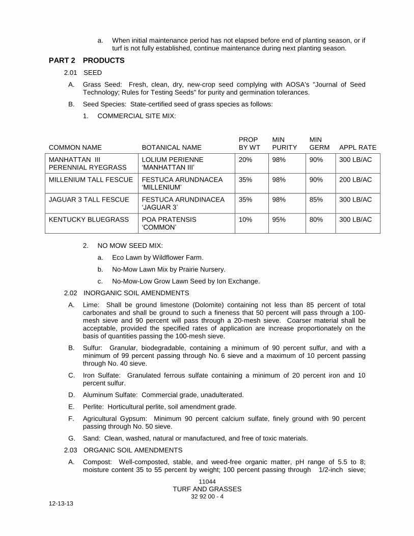
11044
TURF AND GRASSES 32 92 00 - 4
12-13-13
a. When initial maintenance period has not elapsed before end of planting season, or if turf is not fully established, continue maintenance during next planting season.
PART 2 PRODUCTS
2.01 SEED
A. Grass Seed: Fresh, clean, dry, new-crop seed complying with AOSA's "Journal of Seed Technology; Rules for Testing Seeds" for purity and germination tolerances.
B. Seed Species: State-certified seed of grass species as follows:
1. COMMERCIAL SITE MIX:
COMMON NAME BOTANICAL NAME PROP BY WT
MIN PURITY
MIN GERM APPL RATE
MANHATTAN III PERENNIAL RYEGRASS
LOLIUM PERIENNE ‘MANHATTAN III’
20% 98% 90% 300 LB/AC
MILLENIUM TALL FESCUE FESTUCA ARUNDNACEA ‘MILLENIUM’
35% 98% 90% 200 LB/AC
JAGUAR 3 TALL FESCUE FESTUCA ARUNDINACEA ‘JAGUAR 3’
35% 98% 85% 300 LB/AC
KENTUCKY BLUEGRASS POA PRATENSIS ‘COMMON’
10% 95% 80% 300 LB/AC
2. NO MOW SEED MIX:
a. Eco Lawn by Wildflower Farm.
b. No-Mow Lawn Mix by Prairie Nursery.
c. No-Mow-Low Grow Lawn Seed by Ion Exchange.
2.02 INORGANIC SOIL AMENDMENTS
A. Lime: Shall be ground limestone (Dolomite) containing not less than 85 percent of total carbonates and shall be ground to such a fineness that 50 percent will pass through a 100-mesh sieve and 90 percent will pass through a 20-mesh sieve. Coarser material shall be acceptable, provided the specified rates of application are increase proportionately on the basis of quantities passing the 100-mesh sieve.
B. Sulfur: Granular, biodegradable, containing a minimum of 90 percent sulfur, and with a minimum of 99 percent passing through No. 6 sieve and a maximum of 10 percent passing through No. 40 sieve.
C. Iron Sulfate: Granulated ferrous sulfate containing a minimum of 20 percent iron and 10 percent sulfur.
D. Aluminum Sulfate: Commercial grade, unadulterated.
E. Perlite: Horticultural perlite, soil amendment grade.
F. Agricultural Gypsum: Minimum 90 percent calcium sulfate, finely ground with 90 percent passing through No. 50 sieve.
G. Sand: Clean, washed, natural or manufactured, and free of toxic materials.
2.03 ORGANIC SOIL AMENDMENTS
A. Compost: Well-composted, stable, and weed-free organic matter, pH range of 5.5 to 8; moisture content 35 to 55 percent by weight; 100 percent passing through 1/2-inch sieve;
11044
TURF AND GRASSES 32 92 00 - 5
12-13-13
soluble salt content of less than 2.5 decisiemens/m or 1.25 decisiemens/m where seeds, young seedlings, or salt-sensitive plants are used; not exceeding 0.5 percent inert contaminants and free of substances toxic to plantings; and as follows:
1. Organic Matter Content: 50 to 60 percent of dry weight.
B. Muck Peat: Partially decomposed moss peat, native peat, or reed-sedge peat, finely divided or of granular texture, with a pH range of 6 to 7.5, and having a water-absorbing capacity of 1100 to 2000 percent.
C. Wood Derivatives: Decomposed, nitrogen-treated sawdust, ground bark, or wood waste; of uniform texture and free of chips, stones, sticks, soil, or toxic materials.
D. Manure: Well-rotted, unleached, stable or cattle manure containing not more than 25 percent by volume of straw, sawdust, or other bedding materials; free of toxic substances, stones, sticks, soil, weed seed, and material harmful to plant growth.
2.04 FERTILIZERS
A. Bonemeal: Commercial, raw or steamed, finely ground; a minimum of 4 percent nitrogen and 20 percent phosphoric acid.
B. Commercial Fertilizer: Commercial-grade complete fertilizer of neutral character, consisting of fast- and slow-release nitrogen, 50 percent derived from natural organic sources of urea formaldehyde, phosphorous, and potassium in the following composition:
1. Composition: Nitrogen, phosphorous, and potassium in amounts recommended in soil reports from a qualified soil-testing laboratory.
C. Slow-Release Fertilizer: Granular or pelleted fertilizer consisting of 50 percent water-insoluble nitrogen, phosphorus, and potassium in the following composition:
1. Composition: Nitrogen, phosphorous, and potassium in amounts recommended in soil reports from a qualified soil-testing laboratory.
2.05 PLANTING SOILS
A. Planting Soil: Existing, native surface topsoil formed under natural conditions with the duff layer retained during excavation process. Verify suitability of native surface topsoil to produce viable planting soil. Clean soil of roots, plants, sod, stones, clay lumps, and other extraneous materials harmful to plant growth.
1. Supplement with imported topsoil or manufactured topsoil from off-site sources when quantities are insufficient.
2. Mix existing, native surface topsoil and/or imported or manufactured topsoil from off-site sources with the following soil amendments and fertilizers in the following quantities to produce planting soil:
a. Ratio of Loose Compost to Topsoil by Volume: 1:3.
b. Ratio of Loose Muck Peat to Topsoil by Volume: Per topsoil analysis.
c. Ratio of Loose Wood Derivatives to Topsoil by Volume: Per topsoil analysis.
d. Weight of Lime per 1000 Sq. Ft.: per topsoil analysis.
e. Weight of Sulfur, Iron Sulfate, Aluminum Sulfate per 1000 Sq. Ft.: Per topsoil analysis.
f. Weight of Agricultural Gypsum per 1000 Sq. Ft.: Per topsoil analysis.
g. Volume of Sand per 1000 Sq. Ft.: Per topsoil analysis.
h. Weight of Bonemeal per 1000 Sq. Ft.: Per topsoil analysis.
11044
TURF AND GRASSES 32 92 00 - 6
12-13-13
i. Weight of Commercial Fertilizer per 1000 Sq. Ft.: Per manufacturer’s recommendations.
j. Weight of Slow-Release Fertilizer per 1000 Sq. Ft.: Per manufacturer’s recommendations.
B. Supplemental Planting Soil: Imported topsoil or manufactured topsoil from off-site sources. Obtain topsoil displaced from naturally well-drained construction or mining sites where topsoil occurs at least 4 inches deep; do not obtain from bogs or marshes.
1. Additional Properties of Imported Topsoil or Manufactured Topsoil: Screened and free of stones 1/2 inch or larger in any dimension; free of roots, plants, sod, clods, clay lumps, pockets of coarse sand, paint, paint washout, concrete slurry, concrete layers or chunks, cement, plaster, building debris, oils, gasoline, diesel fuel, paint thinner, turpentine, tar, roofing compound, acid, and other extraneous materials harmful to plant growth; free of obnoxious weeds and invasive plants including quackgrass, Johnsongrass, poison ivy, nutsedge, nimblewill, Canada thistle, bindweed, bentgrass, wild garlic, ground ivy, perennial sorrel, and bromegrass; not infested with nematodes, grubs, other pests, pest eggs, or other undesirable organisms and disease-causing plant pathogens; friable and with sufficient structure to give good tilth and aeration. Continuous, air-filled, pore-space content on a volume/volume basis shall be at least 15 percent when moisture is present at field capacity. Soil shall have a field capacity of at least 15 percent on a dry weight basis.
2. Mix imported or manufactured topsoil from off-site sources with the following soil amendments and fertilizers in the following quantities to produce planting soil:
a. Ratio of Loose Compost to Topsoil by Volume: 1:3.
b. Ratio of Loose Muck Peat to Topsoil by Volume: Per topsoil analysis.
c. Ratio of Loose Wood Derivatives to Topsoil by Volume: Per topsoil analysis.
d. Weight of Lime per 1000 Sq. Ft.: per topsoil analysis.
e. Weight of Sulfur,. Iron Sulfate,, Aluminum Sulfate per 1000 Sq. Ft.: Per topsoil analysis.
f. Weight of Agricultural Gypsum per 1000 Sq. Ft.: Per topsoil analysis.
g. Volume of Sand per 1000 Sq. Ft.: Per topsoil analysis.
h. Weight of Bonemeal per 1000 Sq. Ft.: Per topsoil analysis.
i. Weight of Commercial Fertilizer per 1000 Sq. Ft.: Per manufacturer’s recommendations.
j. Weight of Slow-Release Fertilizer per 1000 Sq. Ft.: Per manufacturer’s recommendations.
2.06 MULCHES
A. Straw Mulch: Provide air-dry, clean, mildew- and seed-free, salt hay or threshed straw of wheat, rye, oats, or barley.
B. Compost Mulch: Well-composted, stable, and weed-free organic matter, pH range of 5.5 to 8; moisture content 35 to 55 percent by weight; 100 percent passing through 1/2-inch sieve; soluble salt content of less than 2.5 decisiemens/m or 1.25 decisiemens/m where seeds, young seedlings or salt-sensitive plants are used; not exceeding 0.5 percent inert contaminants and free of substances toxic to plantings; and as follows:
1. Organic Matter Content: 50 to 60 percent of dry weight.
11044
TURF AND GRASSES 32 92 00 - 7
12-13-13
C. Fiber Mulch: Biodegradable, dyed-wood, cellulose-fiber mulch; nontoxic and free of plant-growth or germination inhibitors; with a maximum moisture content of 15 percent and a pH range of 4.5 to 6.5.
D. Nonasphaltic Tackifier: Colloidal tackifier recommended by fiber-mulch manufacturer for slurry application; nontoxic and free of plant-growth or germination inhibitors.
E. Asphalt Emulsion: ASTM D 977, Grade SS-1; nontoxic and free of plant-growth or germination inhibitors.
2.07 PESTICIDES
A. General: Pesticide, registered and approved by EPA, acceptable to authorities having jurisdiction, and of type recommended by manufacturer for each specific problem and as required for Project conditions and application. Do not use restricted pesticides unless authorized in writing by authorities having jurisdiction.
B. Pre-Emergent Herbicide (Selective and Non-Selective): Effective for controlling the germination or growth of weeds within planted areas at the soil level directly below the mulch layer.
C. Post-Emergent Herbicide (Selective and Non-Selective): Effective for controlling weed growth that has already germinated.
2.08 EROSION-CONTROL MATERIALS
A. Erosion-Control Matting: Biodegradable wood excelsior, straw, or coconut-fiber mat enclosed in a photodegradable plastic mesh. Include manufacturer's recommended steel wire staples, 6 inches long.
PART 3 EXECUTION
3.01 EXAMINATION
A. Examine areas to be planted for compliance with requirements and other conditions affecting performance.
1. Verify that no foreign or deleterious material or liquid such as paint, paint washout, concrete slurry, concrete layers or chunks, cement, plaster, oils, gasoline, diesel fuel, paint thinner, turpentine, tar, roofing compound, or acid has been deposited in soil within a planting area.
2. Do not mix or place soils and soil amendments in frozen, wet, or muddy conditions.
3. Suspend soil spreading, grading, and tilling operations during periods of excessive soil moisture until the moisture content reaches acceptable levels to attain the required results.
4. Uniformly moisten excessively dry soil that is not workable and which is too dusty.
B. Proceed with installation only after unsatisfactory conditions have been corrected.
C. If contamination by foreign or deleterious material or liquid is present in soil within a planting area, remove the soil and contamination as directed by Architect and replace with new planting soil.
3.02 PREPARATION
A. Protect structures, utilities, sidewalks, pavements, and other facilities, trees, shrubs, and plantings from damage caused by planting operations.
1. Protect adjacent and adjoining areas from hydroseeding and hydromulching overspray.
2. Protect grade stakes set by others until directed to remove them.
B. Install erosion-control measures to prevent erosion or displacement of soils and discharge of soil-bearing water runoff or airborne dust to adjacent properties and walkways.

11044
TURF AND GRASSES 32 92 00 - 8
12-13-13
3.03 TURF AREA PREPARATION
A. Limit turf subgrade preparation to areas to be planted within 7 days.
B. Newly Graded Subgrades: Loosen subgrade to a minimum depth of 4 inches. Remove foreign material larger than 1/2- inch including, but not limited to: in any dimension, sticks, roots, rubbish, and other extraneous matter and legally dispose of them off Owner's property.
1. Apply fertilizer directly to subgrade before loosening in areas to receive lawn seed. Do not apply fertilizer to areas to receive no-mow seed mix.
2. Thoroughly blend planting soil off-site before spreading or spread topsoil, apply soil amendments and fertilizer on surface, and thoroughly blend planting soil.
a. Delay mixing fertilizer with planting soil if planting will not proceed within 2 days.
b. Mix lime with dry soil before mixing fertilizer.
3. Spread planting soil to a depth of 6 inches but not less than required to meet finish grades after light rolling and natural settlement. Do not spread if planting soil or subgrade is frozen, muddy, or excessively wet.
a. Spread approximately 1/2 the thickness of planting soil over loosened subgrade. Mix thoroughly into top 4 inches of subgrade. Spread remainder of planting soil.
C. Unchanged Subgrades: If turf is to be planted in areas unaltered or undisturbed by excavating, grading, or surface-soil stripping operations, prepare surface soil as follows:
1. Remove existing grass, vegetation, and turf. Do not mix into surface soil.
2. Loosen surface soil to a depth of at least 6 inches. Apply soil amendments and fertilizers according to planting soil mix proportions and mix thoroughly into top 4 inches of soil. Till soil to a homogeneous mixture of fine texture.
a. Apply fertilizer directly to surface soil before loosening in areas to receive lawn seed. Do not apply fertilizer to areas to receive no-mow seed mix.
3. Remove stones larger than 1/2 inch in any dimension including but not limited to: stones, sticks, roots, trash, and other extraneous matter.
4. Legally dispose of waste material, including grass, vegetation, and turf, off Owner's property.
D. Finish Grading: Grade planting areas to a smooth, uniform surface plane with loose, uniformly fine texture. Grade to within plus or minus 1/2 inch of finish elevation. Roll and rake, remove ridges, and fill depressions to meet finish grades. Limit finish grading to areas that can be planted in the immediate future.
E. Moisten prepared area before planting if soil is dry. Water thoroughly and allow surface to dry before planting. Do not create muddy soil.
F. Before planting, obtain Owner’s and Landscape Architect's/Owner’s Representative acceptance of finish grading; restore planting areas if eroded or otherwise disturbed after finish grading.
3.04 PREPARATION FOR EROSION-CONTROL MATERIALS
A. Prepare area as specified in "Turf Area Preparation" Article.
B. For erosion-control matting, install from top of slope, working downward, and as recommended by material manufacturer for site conditions. Fasten as recommended by material manufacturer.
C. Moisten prepared area before planting if surface is dry. Water thoroughly and allow surface to dry before planting. Do not create muddy soil.

11044
TURF AND GRASSES 32 92 00 - 9
12-13-13
3.05 SEEDING
A. Sow seed with spreader or seeding machine. Do not broadcast or drop seed when wind velocity exceeds 5 mph. Evenly distribute seed by sowing equal quantities in two directions at right angles to each other.
1. Do not use wet seed or seed that is moldy or otherwise damaged.
2. Do not seed against existing trees. Limit extent of seed to outside edge of planting saucer.
B. Sow seed at the application rate required of seed species in Part 2.
C. Rake seed lightly into top 1/8 inch of soil, roll lightly, and water with fine spray.
D. Protect seeded areas with slopes exceeding 1:6 with erosion-control matting installed and stapled according to manufacturer's written instructions.
E. Protect seeded areas with erosion-control mats where shown on Drawings; install and anchor according to manufacturer's written instructions.
F. Protect seeded areas with slopes not exceeding 1:6 by spreading straw mulch. Spread uniformly at a minimum rate of 2 tons/acre to form a continuous blanket 1-1/2 inches in loose thickness (1 inch in no-mow mix seeded areas) over seeded areas. Spread by hand, blower, or other suitable equipment.
1. Anchor straw mulch by crimping into soil with suitable mechanical equipment.
2. Bond straw mulch by spraying with asphalt emulsion at a rate of 10 to 13 gal. /1000 sq. ft. Take precautions to prevent damage or staining of structures or other plantings adjacent to mulched areas. Immediately clean damaged or stained areas.
3.06 HYDROSEEDING
A. Hydroseeding: Mix specified seed, fertilizer, and fiber mulch in water, using equipment specifically designed for hydroseed application. Continue mixing until uniformly blended into homogeneous slurry suitable for hydraulic application.
1. Mix slurry with fiber-mulch manufacturer's recommended tackifier.
2. Apply slurry uniformly to all areas to be seeded in a one-step process. Apply slurry at a rate so that mulch component is deposited at not less than 1500-lb/acre dry weight, and seed component is deposited at not less than the specified seed-sowing rate.
3.07 TURF RENOVATION
A. Renovate existing turf damaged by Contractor's operations, such as storage of materials or equipment and movement of vehicles.
1. Reestablish turf where settlement or washouts occur or where minor regrading is required.
2. Install new planting soil as required.
B. Remove sod and vegetation from diseased or unsatisfactory turf areas; do not bury in soil.
C. Remove topsoil containing foreign materials such as oil drippings, fuel spills, stones, gravel, and other construction materials resulting from Contractor's operations, and replace with new planting soil.
D. Mow, dethatch, core aerate, and rake existing turf.
E. Remove weeds before seeding. Where weeds are extensive, apply selective herbicides as required. Do not use pre-emergence herbicides.
F. Remove waste and foreign materials, including weeds, soil cores, grass, vegetation, and turf, and legally dispose of them off Owner's property.

11044
TURF AND GRASSES 32 92 00 - 10
12-13-13
G. Till stripped, bare, and compacted areas thoroughly to a soil depth of 6 inches.
H. Apply soil amendments and initial fertilizers required for establishing new turf and mix thoroughly into top 4 inches of existing soil. Install new planting soil to fill low spots and meet finish grades.
I. Apply seed and protect with straw mulch as required for new turf.
J. Water newly planted areas and keep moist until new turf is established.
3.08 TURF MAINTENANCE
A. Maintain and establish turf by watering, fertilizing, weeding, mowing, trimming, replanting, and performing other operations as required to establish healthy, viable turf. Roll, regrade, and replant bare or eroded areas and remulch to produce a uniformly smooth turf. Provide materials and installation the same as those used in the original installation.
1. Fill in as necessary soil subsidence that may occur because of settling or other processes. Replace materials and turf damaged or lost in areas of subsidence.
2. In areas where mulch has been disturbed by wind or maintenance operations, add new mulch and anchor as required to prevent displacement.
3. Apply treatments as required to keep turf and soil free of pests and pathogens or disease. Use integrated pest management practices whenever possible to minimize the use of pesticides and reduce hazards.
B. Watering: Install and maintain temporary piping, hoses, and turf-watering equipment to convey water from sources and to keep turf uniformly moist to a depth of 4 inches.
1. Schedule watering to prevent wilting, puddling, erosion, and displacement of seed or mulch. Lay out temporary watering system to avoid walking over muddy or newly planted areas.
2. Water turf with fine spray at a minimum rate of 1 inch per week unless rainfall precipitation is adequate.
C. Mow turf as soon as top growth is tall enough to cut. Repeat mowing to maintain specified height without cutting more than 1/3 of grass height. Remove no more than 1/3 of grass-leaf growth in initial or subsequent mowings. Do not delay mowing until grass blades bend over and become matted. Do not mow when grass is wet. Schedule initial and subsequent mowings to maintain the following grass height:
1. 2½ to 3 inches.
D. Turf Postfertilization: Apply fertilizer after initial mowing and when grass is dry.
1. Use fertilizer that will provide actual nitrogen of at least 1 lb/1000 sq. ft. or as recommended by topsoil analysis to turf area.
3.09 SATISFACTORY TURF
A. Turf installations shall meet the following criteria as determined by Landscape Architect/Owner’s Representative.
1. Satisfactory Seeded Turf: At end of maintenance period, a healthy, uniform, close stand of grass has been established, free of weeds and surface irregularities, with coverage exceeding 90 percent over any 10 sq. ft. and bare spots not exceeding 5 by 5 inches .
B. Use specified materials to reestablish turf that does not comply with requirements and continue maintenance until turf is satisfactory.
3.10 PESTICIDE APPLICATION
A. Apply pesticides and other chemical products and biological control agents in accordance with requirements of authorities having jurisdiction and manufacturer's written recommendations.

11044
TURF AND GRASSES 32 92 00 - 11
12-13-13
Coordinate applications with Owner's operations and others in proximity to the Work. Notify Owner before each application is performed.
B. Post-Emergent Herbicides (Selective and Non-Selective): Apply only as necessary to treat already-germinated weeds and in accordance with manufacturer's written recommendations.
3.11 CLEANUP AND PROTECTION
A. Promptly remove soil and debris created by turf work from paved areas. Clean wheels of vehicles before leaving site to avoid tracking soil onto roads, walks, or other paved areas.
B. Erect temporary fencing or barricades and warning signs as required to protect newly planted areas from traffic. Maintain fencing and barricades throughout initial maintenance period and remove after plantings are established.
C. Remove nondegradable erosion-control measures after grass establishment period.
END OF SECTION 32 92 00
11044
PLANTS 32 93 00 - 1
12-13-13
SECTION 32 93 00
PLANTS
PART 1 GENERAL
1.01 RELATED DOCUMENTS
A. Drawings and general provisions of the Contract, including General and Supplementary Conditions and Division 01 Specification Sections, apply to this Section.
1.02 SUMMARY
A. Section Includes:
1. Plants.
2. Planting soils.
3. Tree stabilization.
B. Related Sections:
1. Section 31 10 00 "Site Clearing" for protection of existing trees and plantings, topsoil stripping and stockpiling, and site clearing.
2. Section 31 20 00 "Earth Moving" for excavation, filling, and rough grading and for subsurface aggregate drainage and drainage backfill materials.
3. Section 32 92 00 "Turf and Grasses" for turf (lawn) planting, hydroseeding, and erosion-control materials.
4. Section 33 46 00 "Subdrainage" for below-grade drainage of landscaped areas, paved areas, and wall perimeters.
1.03 DEFINITIONS
A. Backfill: The earth used to replace or the act of replacing earth in an excavation.
B. Balled and Burlapped Stock: Plants dug with firm, natural balls of earth in which they were grown, with ball size not less than diameter and depth recommended by ANSI Z60.1 for type and size of plant required; wrapped with burlap, tied, rigidly supported, and drum laced with twine with the root flare visible at the surface of the ball as recommended by ANSI Z60.1.
C. Balled and Potted Stock: Plants dug with firm, natural balls of earth in which they are grown and placed, unbroken, in a container. Ball size is not less than diameter and depth recommended by ANSI Z60.1 for type and size of plant required.
D. Bare-Root Stock: Plants with a well-branched, fibrous-root system developed by transplanting or root pruning, with soil or growing medium removed, and with not less than minimum root spread according to ANSI Z60.1 for type and size of plant required.
E. Clump: Where three or more young trees were planted in a group and have grown together as a single tree having three or more main stems or trunks.
F. Container-Grown Stock: Healthy, vigorous, well-rooted plants grown in a container, with a well-established root system reaching sides of container and maintaining a firm ball when removed from container. Container shall be rigid enough to hold ball shape and protect root mass during shipping and be sized according to ANSI Z60.1 for type and size of plant required.
G. Duff Layer: The surface layer of native topsoil that is composed of mostly decayed leaves, twigs, and detritus.
H. Finish Grade: Elevation of finished surface of planting soil.
11044
PLANTS 32 93 00 - 2
12-13-13
I. Manufactured Topsoil: Soil produced off-site by homogeneously blending mineral soils or sand with stabilized organic soil amendments to produce topsoil or planting soil.
J. Multi-Stem: Where three or more main stems arise from the ground from a single root crown or at a point right above the root crown.
K. Pesticide: A substance or mixture intended for preventing, destroying, repelling, or mitigating a pest. This includes insecticides, miticides, herbicides, fungicides, rodenticides, and molluscicides. It also includes substances or mixtures intended for use as a plant regulator, defoliant, or desiccant.
L. Pests: Living organisms that occur where they are not desired, or that cause damage to plants, animals, or people. These include insects, mites, grubs, mollusks (snails and slugs), rodents (gophers, moles, and mice), unwanted plants (weeds), fungi, bacteria, and viruses.
M. Planting Area: Areas to be planted.
N. Planting Soil: Standardized topsoil; existing, native surface topsoil; existing, in-place surface soil; imported topsoil; or manufactured topsoil that is modified with soil amendments and perhaps fertilizers to produce a soil mixture best for plant growth.
O. Plant; Plants; Plant Material: These terms refer to vegetation in general, including trees, shrubs, vines, ground covers, ornamental grasses, bulbs, corms, tubers, or herbaceous vegetation.
P. Root Flare: Also called "trunk flare." The area at the base of the plant's stem or trunk where the stem or trunk broadens to form roots; the area of transition between the root system and the stem or trunk.
Q. Stem Girdling Roots: Roots that encircle the stems (trunks) of trees below the soil surface.
R. Subgrade: Surface or elevation of subsoil remaining after excavation is complete, or the top surface of a fill or backfill before planting soil is placed.
S. Subsoil: All soil beneath the topsoil layer of the soil profile, and typified by the lack of organic matter and soil organisms.
T. Surface Soil: Soil that is present at the top layer of the existing soil profile at the Project site. In undisturbed areas, the surface soil is typically topsoil; but in disturbed areas such as urban environments, the surface soil can be subsoil.
1.04 ACTION SUBMITTALS
A. Product Data: For each type of product indicated, including soils.
B. Samples for Verification: For each of the following:
1. Mulch: 1-pint volume of each organic mulch required; in sealed plastic bags labeled with composition of materials by percentage of weight and source of mulch. Each Sample shall be typical of the lot of material to be furnished; provide an accurate representation of color, texture, and organic makeup.
2. Root Barrier: Width of panel by 12 inches.
1.05 INFORMATIONAL SUBMITTALS
A. Qualification Data: For qualified landscape Installer. Include list of similar projects completed by Installer demonstrating Installer's capabilities and experience. Include project names, addresses, and year completed, and include names and addresses of owners' contact persons.
B. Product Certificates: For each type of manufactured product, from manufacturer, and complying with the following:
1. Manufacturer's certified analysis of standard products.
11044
PLANTS 32 93 00 - 3
12-13-13
2. Analysis of other materials by a recognized laboratory made according to methods established by the Association of Official Analytical Chemists, where applicable.
C. Material Test Reports: For existing native surface topsoil and imported or manufactured topsoil if required due to insufficient quantity or quality of stockpiled material.
D. Maintenance Instructions: Recommended procedures to be established by Owner for maintenance of plants during a calendar year. Submit before start of required maintenance periods.
E. Warranty: Sample of special warranty.
1.06 QUALITY ASSURANCE
A. Installer Qualifications: A qualified landscape Installer whose work has resulted in successful establishment of plants.
1. Professional Membership: Installer shall be a member in good standing of either the Professional Landcare Network or the American Nursery and Landscape Association.
2. Experience: Five years’ experience in landscape installation in addition to requirements in Section 01 40 00 "Quality Requirements."
3. Installer's Field Supervision: Require Installer to maintain an experienced full-time supervisor on Project site when work is in progress.
4. Personnel Certifications: Installer's field supervisor shall have certification in [one of] the following categories from the Professional Landcare Network:
a. Certified Landscape Technician - Exterior, with installation specialty area(s), designated CLT-Exterior.
b. Certified Ornamental Landscape Professional designated COLP.
5. Pesticide Applicator: State licensed, commercial.
B. Soil-Testing Laboratory Qualifications: An independent or university laboratory, recognized by the State Department of Agriculture, with the experience and capability to conduct the testing indicated and that specializes in types of tests to be performed.
C. Soil Analysis: For each unamended soil type, furnish soil analysis and a written report by a qualified soil-testing laboratory stating percentages of organic matter; gradation of sand, silt, and clay content; cation exchange capacity; deleterious material; pH; and mineral and plant-nutrient content of the soil.
1. Testing methods and written recommendations shall comply with USDA's Handbook No. 60.
2. The soil-testing laboratory shall oversee soil sampling; with depth, location, and number of samples to be taken per instructions from Landscape Architect/Owner’s Representative. A minimum of three representative samples shall be taken from varied locations for each soil to be used or amended for planting purposes.
3. Report suitability of tested soil for plant growth.
a. Based upon the test results, state recommendations for soil treatments and soil amendments to be incorporated. State recommendations in weight per 1000 sq. ft. or volume per cu. yd. for nitrogen, phosphorus, and potash nutrients and soil amendments to be added to produce satisfactory planting soil suitable for healthy, viable plants.
D. Provide quality, size, genus, species, and variety of plants indicated, complying with applicable requirements in ANSI Z60.1.

11044
PLANTS 32 93 00 - 4
12-13-13
1. Selection of plants purchased under allowances will be made by Landscape Architect/Owner’s Representative, who will tag plants at their place of growth before they are prepared for transplanting.
E. Measurements: Measure according to ANSI Z60.1. Do not prune to obtain required sizes.
1. Trees and Shrubs: Measure with branches and trunks or canes in their normal position. Take height measurements from or near the top of the root flare for field-grown stock and container grown stock. Measure main body of tree or shrub for height and spread; do not measure branches or roots tip to tip. Take caliper measurements 6 inches above the root flare for trees up to 4-inch caliper size, and 12 inches above the root flare for larger sizes.
2. Other Plants: Measure with stems, petioles, and foliage in their normal position.
F. Plant Material Observation: Architect may observe plant material either at place of growth or at site before planting for compliance with requirements for genus, species, variety, cultivar, size, and quality. Landscape Architect/Owner’s Representative retains right to observe trees and shrubs further for size and condition of balls and root systems, pests, disease symptoms, injuries, and latent defects and to reject unsatisfactory or defective material at any time during progress of work. Remove rejected trees or shrubs immediately from Project site.
1. Notify Landscape Architect/Owner’s Representative of sources of planting materials seven days in advance of delivery to site.
G. Preinstallation Conference: Conduct conference at Project site to comply with Division 01 Section “Project Management and Coordination.”
1.07 DELIVERY, STORAGE, AND HANDLING
A. Packaged Materials: Deliver packaged materials in original, unopened containers showing weight, certified analysis, name and address of manufacturer, and indication of conformance with state and federal laws if applicable.
B. Bulk Materials:
1. Do not dump or store bulk materials near structures, utilities, walkways and pavements, or on existing turf areas or plants.
2. Provide erosion-control measures to prevent erosion or displacement of bulk materials, discharge of soil-bearing water runoff, and airborne dust reaching adjacent properties, water conveyance systems, or walkways.
3. Accompany each delivery of bulk fertilizers, lime, and soil amendments with appropriate certificates.
C. Do not prune trees and shrubs before delivery. Protect bark, branches, and root systems from sun scald, drying, wind burn, sweating, whipping, and other handling and tying damage. Do not bend or bind-tie trees or shrubs in such a manner as to destroy their natural shape. Provide protective covering of plants during shipping and delivery. Do not drop plants during delivery and handling.
D. Handle planting stock by root ball.
E. Store bulbs, corms, and tubers in a dry place at 60 to 65 deg F until planting.
F. Deliver plants after preparations for planting have been completed, and install immediately. If planting is delayed more than six hours after delivery, set plants and trees in their appropriate aspect (sun, filtered sun, or shade), protect from weather and mechanical damage, and keep roots moist.
1. Set balled stock on ground and cover ball with soil, peat moss, sawdust, or other acceptable material.
2. Do not remove container-grown stock from containers before time of planting.
11044
PLANTS 32 93 00 - 5
12-13-13
3. Water root systems of plants stored on-site deeply and thoroughly with a fine-mist spray. Water as often as necessary to maintain root systems in a moist, but not overly-wet condition.
1.08 PROJECT CONDITIONS
A. Field Measurements: Verify actual grade elevations, service and utility locations, irrigation system components, and dimensions of plantings and construction contiguous with new plantings by field measurements before proceeding with planting work.
B. Interruption of Existing Services or Utilities: Do not interrupt services or utilities to facilities occupied by Owner or others unless permitted under the following conditions and then only after arranging to provide temporary services or utilities according to requirements indicated:
1. Notify Architect/Owner’s Representative no fewer than two days in advance of proposed interruption of each service or utility.
2. Do not proceed with interruption of services or utilities without Architect/Owner’s Representative written permission.
C. Planting Restrictions: Plant during one of the following periods. Coordinate planting periods with maintenance periods to provide required maintenance from date of Substantial Completion.
1. Spring Planting: April 1 to June 1.
2. Fall Planting: September 1 to November 1.
3. All plantings done between June 2 and August 31 shall be wilt-proof (or approved equivalent) and watering schedule shall be maintained by Contractor until acceptance by Owner.
D. Weather Limitations: Proceed with planting only when existing and forecasted weather conditions permit planting to be performed when beneficial and optimum results may be obtained. Apply products during favorable weather conditions according to manufacturer's written instructions and warranty requirements.
E. Coordination with Lawns: Plant trees, shrubs, and other plants after finish grades are established and before planting lawn unless otherwise indicated.
1. When planting trees, shrubs, and other plants after planting lawn areas, protect lawn areas, and promptly repair damage caused by planting operations.
1.09 WARRANTY
A. Special Warranty: Installer agrees to repair or replace plantings and accessories that fail in materials, workmanship, or growth within specified warranty period.
1. Failures include, but are not limited to, the following:
a. Death and unsatisfactory growth, except for defects resulting from abuse, lack of adequate maintenance, or neglect by Owner, or incidents that are beyond Contractor's control.
b. Structural failures including plantings falling or blowing over.
c. Faulty performance of tree stabilization.
d. Deterioration of metals, metal finishes, and other materials beyond normal weathering.
2. Warranty Periods from Date of Substantial Completion :
a. Trees, Shrubs, Vines, and Ornamental Grasses: 12 months.
b. Ground Covers, Biennials, Perennials, and Other Plants: 12 months.

11044
PLANTS 32 93 00 - 6
12-13-13
3. Include the following remedial actions as a minimum:
a. Immediately remove dead plants and replace unless required to plant in the succeeding planting season.
b. Replace plants that are more than 25 percent dead or in an unhealthy condition at end of warranty period.
c. A limit of one replacement of each plant will be required except for losses or replacements due to failure to comply with requirements.
d. Provide extended warranty for period equal to original warranty period, for replaced plant material.
1.10 MAINTENANCE SERVICE
A. Initial Maintenance Service for Trees and Shrubs: Provide maintenance by skilled employees of landscape Installer. Maintain as required in Part 3. Begin maintenance immediately after plants are installed and continue until plantings are acceptably healthy and well established but for not less than maintenance period below.
1. Maintenance Period: 12 months from date of Substantial Completion.
B. Initial Maintenance Service for Ground Cover and Other Plants: Provide maintenance by skilled employees of landscape Installer. Maintain as required in Part 3. Begin maintenance immediately after plants are installed and continue until plantings are acceptably healthy and well established but for not less than maintenance period below.
1. Maintenance Period: 12 months from date of Substantial Completion.
PART 2 PRODUCTS
2.01 PLANT MATERIAL
A. General: Furnish nursery-grown plants true to genus, species, variety, cultivar, stem form, shearing, and other features indicated in Plant Schedule or Plant Legend shown on Drawings and complying with ANSI Z60.1; and with healthy root systems developed by transplanting or root pruning. Provide well-shaped, fully branched, healthy, vigorous stock, densely foliated when in leaf and free of disease, pests, eggs, larvae, and defects such as knots, sun scald, injuries, abrasions, and disfigurement.
1. Trees with damaged, crooked, or multiple leaders; tight vertical branches where bark is squeezed between two branches or between branch and trunk ("included bark"); crossing trunks; cut-off limbs more than 3/4 inch in diameter; or with stem girdling roots will be rejected.
2. Collected Stock: Do not use plants harvested from the wild, from native stands, from an established landscape planting, or not grown in a nursery unless otherwise indicated.
B. Provide plants of sizes, grades, and ball or container sizes complying with ANSI Z60.1 for types and form of plants required. Plants of a larger size may be used if acceptable to Architect, with a proportionate increase in size of roots or balls.
C. Root-Ball Depth: Furnish trees and shrubs with root balls measured from top of root ball, which shall begin at root flare according to ANSI Z60.1. Root flare shall be visible before planting.
D. Labeling: Label each plant of each variety, size, and caliper with a securely attached, waterproof tag bearing legible designation of common name and full scientific name, including genus and species. Include nomenclature for hybrid, variety, or cultivar, if applicable for the plant as shown on Drawings.
E. If formal arrangements or consecutive order of plants is shown on Drawings, select stock for uniform height and spread, and number the labels to assure symmetry in planting.

11044
PLANTS 32 93 00 - 7
12-13-13
2.02 INORGANIC SOIL AMENDMENTS
A. Lime: Shall be ground limestone (Dolomite) containing not less than 85 percent of total carbonates and shall be ground to such fineness that 50-percent will pass through a 100-mesh sieve and 90 percent will pass through a 20-mesh sieve. Coarser material shall be acceptable, provided the specified rates of application are increased proportionately on the basis of quantities passing the 100-mesh sieve.
B. Sulfur: Granular, biodegradable, and containing a minimum of 90 percent sulfur, with a minimum of 99 percent passing through No. 6 sieve and a maximum of 10 percent passing through No. 40 sieve.
C. Iron Sulfate: Granulated ferrous sulfate containing a minimum of 20 percent iron and 10 percent sulfur.
D. Aluminum Sulfate: Commercial grade, unadulterated.
E. Perlite: Horticultural perlite, soil amendment grade.
F. Agricultural Gypsum: Minimum 90 percent calcium sulfate, finely ground with 90 percent passing through No. 50 sieve.
G. Sand: Clean, washed, natural or manufactured, and free of toxic materials.
2.03 ORGANIC SOIL AMENDMENTS
A. Compost: Well-composted, stable, and weed-free organic matter, pH range of 5.5 to 8; moisture content 35 to 55 percent by weight; 100 percent passing through 1/2-inch sieve; soluble salt content of less than 2.5 decisiemens/m and less than 1.25 decisiemens/m where seeds, young seedlings, or salt sensitive plants are used; not exceeding 0.5 percent inert contaminants and free of substances toxic to plantings; and as follows:
1. Organic Matter Content: 50 to 60 percent of dry weight.
2. Feedstock: Agricultural, food, or industrial residuals; biosolids; yard trimmings; or source-separated or compostable mixed solid waste.
B. Sphagnum Peat: Partially decomposed sphagnum peat moss, finely divided or granular texture, with a pH range of 3.4 to 4.8.
C. Muck Peat: Partially decomposed moss peat, native peat, or reed-sedge peat, finely divided or of granular texture, with a pH range of 6 to 7.5, and having a water-absorbing capacity of 1100 to 2000 percent.
D. Wood Derivatives: Decomposed, nitrogen-treated sawdust, ground bark, or wood waste; of uniform texture and free of chips, stones, sticks, soil, or toxic materials.
E. Manure: Well-rotted, unleached, stable or cattle manure containing not more than 25 percent by volume of straw, sawdust, or other bedding materials; free of toxic substances, stones, sticks, soil, weed seed, debris, and material harmful to plant growth.
2.04 FERTILIZERS
A. Bonemeal: Commercial, raw or steamed, finely ground; a minimum of 4 percent nitrogen and 20 percent phosphoric acid.
B. Commercial Fertilizer: Commercial-grade complete fertilizer of neutral character, consisting of fast- and slow-release nitrogen, 50 percent derived from natural organic sources of urea formaldehyde, phosphorous, and potassium in the following composition:
1. Composition: Nitrogen, phosphorous, and potassium in amounts recommended in soil reports from a qualified soil-testing laboratory.
C. Slow-Release Fertilizer: Granular or pelleted fertilizer consisting of a minimum of 50 percent water-insoluble nitrogen, phosphorus, and potassium in the following composition:
11044
PLANTS 32 93 00 - 8
12-13-13
1. Composition: Nitrogen, phosphorous, and potassium in amounts recommended in soil reports from a qualified soil-testing laboratory.
D. Planting Tablets: Tightly compressed chip type, long-lasting, slow-release, commercial-grade planting fertilizer in tablet form. Tablets shall break down with soil bacteria, converting nutrients into a form that can be absorbed by plant roots.
1. Size: 5-gram for small plants and ground covers, 10-gram for up to 1-gallon size plants, and 21-gram for 1-gallon or greater plants tablets.
2. Nutrient Composition: 20 percent nitrogen, 10 percent phosphorous, and 5 percent potassium, by weight plus micronutrients.
E. Chelated Iron: Commercial-grade FeEDDHA for dicots and woody plants, and commercial-grade FeDTPA for ornamental grasses and monocots.
2.05 PLANTING SOILS
A. Planting Soil: Existing, native surface topsoil formed under natural conditions with the duff layer retained during excavation process and stockpiled on-site. Verify suitability of native surface topsoil to produce viable planting soil. Clean soil of roots, plants, sod, stones, clay lumps, and other extraneous materials harmful to plant growth.
1. Supplement with imported topsoil or manufactured topsoil from off-site sources planting soil when quantities are insufficient.
2. Mix existing, native surface topsoil and/or imported topsoil or manufactured topsoil from off-site sources with the following soil amendments and fertilizers in the following quantities to produce planting soil:
a. Ratio of Loose Compost to Topsoil by Volume: 1:3.
b. Ratio of Loose Peat to Topsoil by Volume: Per topsoil analysis.
c. Ratio of Loose Wood Derivatives to Topsoil by Volume: Per topsoil analysis.
d. Weight of Lime per 1000 Sq. Ft.: Per topsoil analysis.
e. Weight of Sulfur, Iron Sulfate or Aluminum Sulfate per 1000 Sq. Ft.: Per topsoil analysis.
f. Weight of Agricultural Gypsum per 1000 Sq. Ft.: Per topsoil analysis.
g. Volume of Sand Plus 1000 Sq. Ft.: Per topsoil analysis.
h. Weight of Bonemeal per 1000 Sq. Ft.: Per topsoil analysis.
i. Weight of Commercial Fertilizer per 1000 Sq. Ft.: Per manufacturer’s recommendations.
j. Weight of Slow-Release Fertilizer per 1000 Sq. Ft.: Per manufacturer’s recommendations.
B. Supplemental Planting Soil: Imported topsoil or manufactured topsoil from off-site sources. Obtain topsoil displaced from naturally well-drained construction or mining sites where topsoil occurs at least 4 inches deep; do not obtain from bogs, or marshes.
1. Additional Properties of Imported Topsoil or Manufactured Topsoil: Screened and free of stones ½-inch or larger in any dimension; free of roots, plants, sod, clods, clay lumps, pockets of coarse sand, paint, paint washout, concrete slurry, concrete layers or chunks, cement, plaster, building debris, oils, gasoline, diesel fuel, paint thinner, turpentine, tar, roofing compound, acid, and other extraneous materials harmful to plant growth; free of obnoxious weeds and invasive plants including quackgrass, Johnsongrass, poison ivy, nutsedge, nimblewill, Canada thistle, bindweed, bentgrass, wild garlic, ground ivy, perennial sorrel, and bromegrass; not infested with nematodes; grubs; or other pests, pest eggs, or other undesirable organisms and disease-causing plant pathogens; friable

11044
PLANTS 32 93 00 - 9
12-13-13
and with sufficient structure to give good tilth and aeration. Continuous, air-filled pore space content on a volume/volume basis shall be at least 15 percent when moisture is present at field capacity. Soil shall have a field capacity of at least 15 percent on a dry weight basis.
2. Mix imported topsoil or manufactured topsoil with the following soil amendments and fertilizers in the following quantities to produce planting soil:
a. Ratio of Loose Compost to Topsoil by Volume: 1:3.
b. Ratio of Loose Peat to Topsoil by Volume: Per topsoil analysis.
c. Ratio of Loose Wood Derivatives to Topsoil by Volume: Per topsoil analysis.
d. Weight of Lime per 1000 Sq. Ft.: Per topsoil analysis.
e. Weight of Sulfur, Iron Sulfate or Aluminum Sulfate per 1000 Sq. Ft.: Per topsoil analysis.
f. Weight of Agricultural Gypsum per 1000 Sq. Ft.: Per topsoil analysis.
g. Volume of Sand Plus 1000 Sq. Ft.: Per topsoil analysis.
h. Weight of Bonemeal per 1000 Sq. Ft.: Per topsoil analysis.
i. Weight of Commercial Fertilizer per 1000 Sq. Ft.: Per manufacturer’s recommendations.
j. Weight of Slow-Release Fertilizer per 1000 Sq. Ft.: Per manufacturer’s recommendations.
2.06 MULCHES
A. Organic Mulch: Free from deleterious materials and suitable as a top dressing of trees and shrubs, consisting of one of the following:
1. Type: Double shredded hardwood bark mulch, aged two years.
2. Color: Natural.
B. Compost Mulch: Well-composted, stable, and weed-free organic matter, pH range of 5.5 to 8; moisture content 35 to 55 percent by weight; 100 percent passing through 1/2-inch sieve; soluble salt content of less than 2.5 decisiemens/m and less than 1.25 decisiemens/m where seeds, young seedlings or slat-sensitive plants are used; not exceeding 0.5 percent inert contaminants and free of substances toxic to plantings; and as follows:
1. Organic Matter Content: 50 to 60 percent of dry weight.
2.07 PESTICIDES
A. General: Pesticide registered and approved by EPA, acceptable to authorities having jurisdiction, and of type recommended by manufacturer for each specific problem and as required for Project conditions and application. Do not use restricted pesticides unless authorized in writing by authorities having jurisdiction.
B. Pre-Emergent Herbicide (Selective and Non-Selective): Effective for controlling the germination or growth of weeds within planted areas at the soil level directly below the mulch layer.
C. Post-Emergent Herbicide (Selective and Non-Selective): Effective for controlling weed growth that has already germinated.
2.08 TREE STABILIZATION MATERIALS
A. Stakes and Guys:

11044
PLANTS 32 93 00 - 10
12-13-13
1. Upright and Guy Stakes: Rough-sawn, sound, new hardwood , free of knots, holes, cross grain, and other defects, 2-by-2-inch nominal by length indicated, pointed at one end.
2. Flexible Ties: Wide rubber or elastic bands or straps of length required to reach stakes or turnbuckles.
3. Guys and Tie Wires: ASTM A 641/A 641M, Class 1, galvanized-steel wire, two-strand, twisted, 0.106 inch in diameter.
4. Guy Cables: Five-strand, 3/16-inch- diameter, galvanized-steel cable, with zinc-coated turnbuckles, a minimum of 3 inches long, with two 3/8-inch galvanized eyebolts.
5. Flags: Standard surveyor's plastic flagging tape, white, 6 inches long.
6. Proprietary Staking-and-Guying Devices: Proprietary stake and adjustable tie systems to secure each new planting by plant stem; sized as indicated and per manufacturer's written recommendations.
2.09 MISCELLANEOUS PRODUCTS
A. Wood Pressure-Preservative Treatment: AWPA C2, with waterborne preservative for soil and freshwater use, acceptable to authorities having jurisdiction, and containing no arsenic; including ammoniacal copper arsenate, ammoniacal copper zinc arsenate, and chromated copper arsenate.
B. Antidesiccant: Water-insoluble emulsion, permeable moisture retarder, film forming, for trees and shrubs. Deliver in original, sealed, and fully labeled containers and mix according to manufacturer's written instructions.
C. Burlap: Non-synthetic, biodegradable.
PART 3 EXECUTION
3.01 EXAMINATION
A. Examine areas to receive plants for compliance with requirements and conditions affecting installation and performance.
1. Verify that no foreign or deleterious material or liquid such as paint, paint washout, concrete slurry, concrete layers or chunks, cement, plaster, oils, gasoline, diesel fuel, paint thinner, turpentine, tar, roofing compound, or acid has been deposited in soil within a planting area.
2. Do not mix or place soils and soil amendments in frozen, wet, or muddy conditions.
3. Suspend soil spreading, grading, and tilling operations during periods of excessive soil moisture until the moisture content reaches acceptable levels to attain the required results.
4. Uniformly moisten excessively dry soil that is not workable and which is too dusty.
B. Proceed with installation only after unsatisfactory conditions have been corrected.
C. If contamination by foreign or deleterious material or liquid is present in soil within a planting area, remove the soil and contamination as directed by Landscape Architect/Owner’s Representative and replace with new planting soil.
3.02 PREPARATION
A. Protect structures, utilities, sidewalks, pavements, and other facilities and turf areas and existing plants from damage caused by planting operations.
B. Install erosion-control measures to prevent erosion or displacement of soils and discharge of soil-bearing water runoff or airborne dust to adjacent properties and walkways.
11044
PLANTS 32 93 00 - 11
12-13-13
C. Lay out individual tree and shrub locations and areas for multiple plantings. Stake locations, outline areas, adjust locations when requested, and obtain Landscape Architect/Owner’s Representative acceptance of layout before excavating or planting. Make minor adjustments as required.
D. Trunk Wrapping: Prior to transporting from nursery, inspect tree trunks for injury, improper pruning, and insect infestation; take corrective measures required before wrapping, including denial of tree. Prior to transporting from nursery, wrap trees of 2-inch caliper and larger with white or light-colored trunk-wrap tape. Start at base of trunk and spiral cover trunk to height of first branches. Overlap wrap, exposing half the width, and securely attach with masking tape (not duct or electrical tape or wire ties). During inspection, by Landscape Architect/Owner’s Representative, at delivery of trees to the project site, remove trunk wrap from tree. Replace trunk wrap to trees a directed by Landscape Architect/Owner’s Representative.
E. Apply antidesiccant to trees and shrubs using power spray to provide an adequate film over trunks (before wrapping), branches, stems, twigs, and foliage to protect during digging, handling, and transportation.
1. If deciduous trees or shrubs are moved in full leaf, spray with antidesiccant at nursery before moving and again two weeks after planting.
F. Wrap trees and shrubs with burlap fabric over trunks, branches, stems, twigs, and foliage to protect from wind and other damage during digging, handling, and transportation.
3.03 PLANTING AREA ESTABLISHMENT
A. Loosen subgrade of planting areas to a minimum depth of 6 inches. Remove stones larger than 1/2 inch in any dimension and sticks, roots, rubbish, and other extraneous matter and legally dispose of them off Owner's property.
1. Apply fertilizer directly to subgrade before loosening.
2. Thoroughly blend planting soil off-site before spreading or spread topsoil, apply soil amendments and fertilizer on surface, and thoroughly blend planting soil.
a. Delay mixing fertilizer with planting soil if planting will not proceed within a few days.
b. Mix lime with dry soil before mixing fertilizer.
3. Spread planting soil to a depth of 12 inches but not less than required to meet finish grades after natural settlement. Do not spread if planting soil or subgrade is frozen, muddy, or excessively wet.
a. Spread approximately one-half the thickness of planting soil over loosened subgrade. Mix thoroughly into top 4 inches of subgrade. Spread remainder of planting soil.
B. Finish Grading: Grade planting areas to a smooth, uniform surface plane with loose, uniformly fine texture. Roll and rake, remove ridges, and fill depressions to meet finish grades.
C. Before planting, obtain Landscape Architect/Owner’s Representative acceptance of finish grading; restore planting areas if eroded or otherwise disturbed after finish grading.
3.04 EXCAVATION FOR TREES AND SHRUBS
A. Planting Pits and Trenches: Excavate circular planting pits with sides sloping inward at a 60-degree angle. Excavations with vertical sides are not acceptable. Trim perimeter of bottom leaving center area of bottom raised slightly to support root ball and assist in drainage away from center. Do not further disturb base. Ensure that root ball will sit on undisturbed base soil to prevent settling. Scarify sides of planting pit smeared or smoothed during excavation.
1. Excavate approximately twice times as wide as ball diameter for balled and burlapped and container-grown stock.

11044
PLANTS 32 93 00 - 12
12-13-13
2. Do not excavate deeper than depth of the root ball, measured from the root flare to the bottom of the root ball.
3. If area under the plant was initially dug too deep, add soil to raise it to the correct level and thoroughly tamp the added soil to prevent settling.
4. Maintain required angles of repose of adjacent materials. Do not excavate subgrades of adjacent paving, structures, hardscapes, or other new or existing improvements.
5. Maintain supervision of excavations during working hours.
6. Keep excavations covered or otherwise protected when unattended by Installer's personnel.
7. If drain tile is shown on Drawings or required under planting areas, excavate to top of porous backfill over tile.
B. Subsoil and topsoil removed from excavations may be used as planting soil if amended per planting soil portion of this section.
C. Obstructions: Notify Architect if unexpected rock or obstructions detrimental to trees or shrubs are encountered in excavations.
1. Hardpan Layer: Drill 6-inch- diameter holes, 24 inches apart, into free-draining strata or to a depth of 10 feet, whichever is less, and backfill with free-draining material.
D. Prior to planting of tree, notify Landscape Architect/Owner’s Representative if subsoil conditions evidence unexpected water seepage or retention in tree or shrub planting pits. Do not plant tree in pit until drainage condition is corrected and given approval by Landscape Architect/Owner’s Representative.
E. Fill excavations with water and allow to percolate away before positioning trees and shrubs.
3.05 TREE, SHRUB, AND VINE PLANTING
A. Before planting, verify that root flare is visible at top of root ball according to ANSI Z60.1. If root flare is not visible, remove soil in a level manner from the root ball to where the top-most root emerges from the trunk. After soil removal to expose the root flare, verify that root ball still meets size requirements.
B. Remove stem girdling roots and kinked roots. Remove injured roots by cutting cleanly; do not break.
C. Set balled and burlapped stock plumb and in center of planting pit or trench with root flare 2 inches above adjacent finish grades.
1. Use planting soil for backfill.
2. After placing some backfill around root ball to stabilize plant, carefully cut and remove burlap, rope, and wire baskets from tops of root balls and from sides, but do not remove from under root balls. Remove pallets, if any, before setting. Do not use planting stock if root ball is cracked or broken before or during planting operation.
3. Backfill around root ball in layers, tamping to settle soil and eliminate voids and air pockets. When planting pit is approximately one-half filled, water thoroughly before placing remainder of backfill. Repeat watering until no more water is absorbed.
4. Place planting tablets in each planting pit when pit is approximately one-half filled; in amounts recommended in soil reports from soil-testing laboratory. Place tablets beside the root ball about 1 inch from root tips; do not place tablets in bottom of the hole.
5. Continue backfilling process. Water again after placing and tamping final layer of soil.
D. Set container-grown stock plumb and in center of planting pit or trench with root flare 2 inches above adjacent finish grades.
11044
PLANTS 32 93 00 - 13
12-13-13
1. Use planting soil for backfill.
2. Carefully remove root ball from container without damaging root ball or plant.
3. Backfill around root ball in layers, tamping to settle soil and eliminate voids and air pockets. When planting pit is approximately one-half filled, water thoroughly before placing remainder of backfill. Repeat watering until no more water is absorbed.
4. Place planting tablets in each planting pit when pit is approximately one-half filled; in amounts recommended in soil reports from soil-testing laboratory. Place tablets beside the root ball about 1 inch from root tips; do not place tablets in bottom of the hole.
5. Continue backfilling process. Water again after placing and tamping final layer of soil.
E. When planting on slopes, set the plant so the root flare on the uphill side is flush with the surrounding soil on the slope; the edge of the root ball on the downhill side will be above the surrounding soil. Apply enough soil to cover the downhill side of the root ball.
3.06 MECHANIZED TREE SPADE PLANTING
A. Trees may be planted with an approved mechanized tree spade at the designated locations. Do not use tree spade to move trees larger than the maximum size allowed for a similar field-grown, balled-and-burlapped root-ball diameter according to ANSI Z60.1, or larger than the manufacturer's maximum size recommendation for the tree spade being used, whichever is smaller.
B. When extracting the tree, center the trunk within the tree spade and move tree with a solid ball of earth.
C. Cut exposed roots cleanly during transplanting operations.
D. Use the same tree spade to excavate the planting hole as was used to extract and transport the tree.
E. Plant trees as shown on Drawings, following procedures in "Tree, Shrub, and Vine Planting" Article.
F. Where possible, orient the tree in the same direction as in its original location.
3.07 TREE, SHRUB, AND VINE PRUNING
A. Remove only dead, dying, or broken branches. Do not prune for shape.
B. Prune, thin, and shape trees, shrubs, and vines as directed by Landscape Architect/Owner’s Representative.
C. Prune, thin, and shape trees, shrubs, and vines according to standard professional horticultural and arboricultural practices. Unless otherwise indicated by Landscape Architect/Owner’s Representative, do not cut tree leaders; remove only injured, dying, or dead branches from trees and shrubs; and prune to retain natural character.
D. Do not apply pruning paint to wounds.
3.08 TREE STABILIZATION
A. Install trunk stabilization as follows unless otherwise indicated:
1. Upright Staking and Tying: Stake trees of 2- through 5-inch caliper. Stake trees of less than 2-inch caliper only as required or as directed by Landscape Architect/Owner’s Representative to prevent wind tip out. Use a minimum of two stakes of length required to penetrate at least 18 inches below bottom of backfilled excavation and to extend one-third of trunk height above grade. Set vertical stakes and space to avoid penetrating root balls or root masses.
11044
PLANTS 32 93 00 - 14
12-13-13
2. Use two stakes for trees up to 12 feet high and 2-1/2 inches or less in caliper; three stakes for trees less than 14 feet high and up to 4 inches in caliper. Space stakes equally around trees.
3. Support trees with bands of flexible ties at contact points with tree trunk. Allow enough slack to avoid rigid restraint of tree.
4. Support trees with two strands of tie wire, connected to the brass grommets of tree-tie webbing at contact points with tree trunk. Allow enough slack to avoid rigid restraint of tree.
B. Staking and Guying: Stake and guy trees more than 14 feet in height and more than 3 inches in caliper unless otherwise indicated. Securely attach no fewer than three guys to stakes 30 inches long, driven to grade.
1. Site-Fabricated Staking-and-Guying Method:
a. For trees more than 6 inches in caliper, anchor guys to wood deadmen buried at least 36 inches below grade. Provide turnbuckle for each guy wire and tighten securely.
b. Support trees with bands of flexible ties at contact points with tree trunk and reaching to turnbuckle. Allow enough slack to avoid rigid restraint of tree.
c. Support trees with strands of cable or multiple strands of tie wire, connected to the brass grommets of tree-tie webbing at contact points with tree trunk and reaching to turnbuckle. Allow enough slack to avoid rigid restraint of tree.
d. Attach flags to each guy wire, 30 inches above finish grade.
e. Paint turnbuckles with luminescent white paint.
2. Proprietary Staking and Guying Device: Install staking and guying system sized and positioned as recommended by manufacturer unless otherwise indicated and according to manufacturer's written instructions.
3.09 ROOT-BARRIER INSTALLATION
A. Install root barrier where trees are planted within 60 inches of paving or other hardscape elements, such as walls, curbs, and walkways unless otherwise shown on Drawings.
B. Align root barrier vertically and run it linearly along and adjacent to the paving or other hardscape elements to be protected from invasive roots.
C. Install root barrier continuously for a distance of 60 inches in each direction from the tree trunk, for a total distance of 10 feet per tree. If trees are spaced closer, use a single continuous piece of root barrier.
1. Position top of root barrier per manufacturer's recommendations.
2. Overlap root barrier a minimum of 12 inches at joints.
3. Do not distort or bend root barrier during construction activities.
4. Do not install root barrier surrounding the root ball of tree.
3.10 GROUND COVER AND PLANT PLANTING
A. Set out and space ground cover and plants other than trees, shrubs, and vines in even rows with triangular spacing.
B. Use planting soil for backfill.
C. Dig holes large enough to allow spreading of roots.
D. For rooted cutting plants supplied in flats, plant each in a manner that will minimally disturb the root system but to a depth not less than two nodes.

11044
PLANTS 32 93 00 - 15
12-13-13
E. Work soil around roots to eliminate air pockets and leave a slight saucer indentation around plants to hold water.
F. Water thoroughly after planting, taking care not to cover plant crowns with wet soil.
G. Protect plants from hot sun and wind; remove protection if plants show evidence of recovery from transplanting shock.
3.11 PLANTING AREA MULCHING
A. Mulch backfilled surfaces of planting areas and other areas indicated.
1. Trees and Tree-like Shrubs in Turf Areas: Apply organic mulch ring of 3-inch thickness, as shown on drawings. Do not place mulch against trunks or stems.
2. Organic Mulch in Planting Areas: Apply 3-inch average thickness of organic mulch over whole surface of planting area, and finish level with adjacent finish grades. Do not place mulch against trunks or stems.
3.12 PLANT MAINTENANCE
A. Maintain plantings by pruning, cultivating, watering, weeding, fertilizing, mulching, restoring planting saucers, adjusting and repairing tree-stabilization devices, resetting to proper grades or vertical position, and performing other operations as required to establish healthy, viable plantings. Spray or treat as required to keep trees and shrubs free of insects and disease.
B. Fill in as necessary soil subsidence that may occur because of settling or other processes. Replace mulch materials damaged or lost in areas of subsidence.
C. Apply treatments as required to keep plant materials, planted areas, and soils free of pests and pathogens or disease. Use integrated past management practices whenever possible to minimize the use of pesticides and reduce hazards. Treatments include physical controls such as hosing off foliage, mechanical controls such as traps, and biological control agents.
3.13 PESTICIDE APPLICATION
A. Apply pesticides and other chemical products and biological control agents in accordance with authorities having jurisdiction and manufacturer's written recommendations. Coordinate applications with Owner's operations and others in proximity to the Work. Notify Owner before each application is performed.
B. Pre-Emergent Herbicides (Selective and Non-Selective): Apply to tree, shrub, and ground-cover areas in accordance with manufacturer's written recommendations. Do not apply to seeded areas.
C. Post-Emergent Herbicides (Selective and Non-Selective): Apply only as necessary to treat already-germinated weeds and in accordance with manufacturer's written recommendations.
3.14 CLEANUP AND PROTECTION
A. During planting, keep adjacent paving and construction clean and work area in an orderly condition.
B. Protect plants from damage due to landscape operations and operations of other contractors and trades. Maintain protection during installation and maintenance periods. Treat, repair, or replace damaged plantings.
C. After installation and before Substantial Completion, remove nursery tags, nursery stakes, tie tape, labels, wire, burlap, and other debris from plant material, planting areas, and Project site.
3.15 DISPOSAL
A. Remove surplus soil and waste material including excess subsoil, unsuitable soil, trash, and debris and legally dispose of them off Owner's property.

11044
PLANTS 32 93 00 - 16
12-13-13
END OF SECTION 32 93 00

11044
COMMON WORK RESULTS FOR UTILITIES 33 05 00 - 1
12-13-13
SECTION 33 05 00
COMMON WORK RESULTS FOR UTILITIES
PART 1 GENERAL
1.01 RELATED DOCUMENTS
A. Drawings and general provisions of the Contract, including General and Supplementary Conditions and Division 01 Specification Sections, apply to this Section.
1.02 SUMMARY
A. This Section includes the following:
1. Piping joining materials.
2. Transition fittings.
3. Dielectric fittings.
4. Sleeves.
5. Grout.
6. Flowable fill.
7. Piped utility demolition.
8. Piping system common requirements.
9. Painting.
10. Concrete bases.
11. Metal supports and anchorages.
1.03 DEFINITIONS
A. Exposed Installations: Exposed to view outdoors or subject to outdoor ambient temperatures and weather conditions.
B. Concealed Installations: Concealed from view and protected from weather conditions and physical contact by building occupants but subject to outdoor ambient temperatures. Examples include installations within unheated shelters.
C. ABS: Acrylonitrile-butadiene-styrene plastic.
D. CPVC: Chlorinated polyvinyl chloride plastic.
E. PE: Polyethylene plastic.
F. PVC: Polyvinyl chloride plastic.
1.04 SUBMITTALS
A. Product Data: For the following:
1. Dielectric fittings.
2. Identification devices.
B. Welding certificates.
1.05 QUALITY ASSURANCE
A. Steel Support Welding: Qualify procedures and personnel according to AWS D1.1/D1.1M, "Structural Welding Code - Steel."
B. Steel Piping Welding: Qualify processes and operators according to ASME Boiler and Pressure Vessel Code: Section IX, "Welding and Brazing Qualifications."
1. Comply with provisions in ASME B31 Series, "Code for Pressure Piping."
2. Certify that each welder has passed AWS qualification tests for welding processes involved and that certification is current.
C. Comply with ASME A13.1 for lettering size, length of color field, colors, and viewing angles of identification devices.
11044
COMMON WORK RESULTS FOR UTILITIES 33 05 00 - 2
12-13-13
1.06 DELIVERY, STORAGE, AND HANDLING
A. Deliver pipes and tubes with factory-applied end caps. Maintain end caps through shipping, storage, and handling to prevent pipe end damage and to prevent entrance of dirt, debris, and moisture.
B. Store plastic pipes protected from direct sunlight. Support to prevent sagging and bending.
1.07 COORDINATION
A. Coordinate installation of required supporting devices and set sleeves in poured-in-place concrete and other structural components as they are constructed.
B. Coordinate installation of identifying devices after completing covering and painting if devices are applied to surfaces.
C. Coordinate size and location of concrete bases. Formwork, reinforcement, and concrete requirements are specified in Division 03.
PART 2 PRODUCTS
2.01 PIPING JOINING MATERIALS
A. Pipe-Flange Gasket Materials: Suitable for chemical and thermal conditions of piping system contents.
1. ASME B16.21, non-metallic, flat, asbestos free, 1/8-inch maximum thickness, unless otherwise indicated.
a. Full-Face Type: For flat-face, Class 125, cast-iron and cast-bronze flanges.
b. Narrow-Face Type: For raised-face, Class 250, cast-iron and steel flanges.
2. AWWA C110, rubber, flat face, 1/8 inch thick, unless otherwise indicated; and full-face or ring type, unless otherwise indicated.
B. Flange Bolts and Nuts: ASME B18.2.1, carbon steel, unless otherwise indicated.
C. Plastic, Pipe-Flange Gasket, Bolts, and Nuts: Type and material recommended by piping system manufacturer, unless otherwise indicated.
D. Solder Filler Metals: ASTM B 32, lead-free alloys. Include water-flushable flux according to ASTM B 813.
E. Brazing Filler Metals: AWS A5.8, BCuP Series, copper-phosphorus alloys for general-duty brazing, unless otherwise indicated; and AWS A5.8, BAg1, silver alloy for refrigerant piping, unless otherwise indicated.
F. Welding Filler Metals: Comply with AWS D10.12/D10.12M for welding materials appropriate for wall thickness and chemical analysis of steel pipe being welded.
G. Solvent Cements for Joining Plastic Piping:
1. ABS Piping: ASTM D 2235.
2. CPVC Piping: ASTM F 493.
3. PVC Piping: ASTM D 2564. Include primer according to ASTM F 656.
4. PVC to ABS Piping Transition: ASTM D 3138.
H. Fiberglass Pipe Adhesive: As furnished or recommended by pipe manufacturer.
2.02 TRANSITION FITTINGS
A. Transition Fittings, General: Same size as, and with pressure rating at least equal to and with ends compatible with, piping to be joined.
B. Transition Couplings NPS 1-1/2 and Smaller:
1. Underground Piping: Manufactured piping coupling or specified piping system fitting.
2. Aboveground Piping: Specified piping system fitting.
C. AWWA Transition Couplings NPS 2 and Larger:
1. Description: AWWA C219, metal sleeve-type coupling for underground pressure piping.
D. Plastic-to-Metal Transition Fittings:

11044
COMMON WORK RESULTS FOR UTILITIES 33 05 00 - 3
12-13-13
1. Description: CPVC and PVC one-piece fitting with manufacturer's Schedule 80 equivalent dimensions; one end with threaded brass insert, and one solvent-cement-joint or threaded end.
E. Plastic-to-Metal Transition Unions:
1. Description: MSS SP-107, CPVC and PVC four-part union. Include brass or stainless-steel threaded end, solvent-cement-joint or threaded plastic end, rubber O-ring, and union nut.
F. Flexible Transition Couplings for Underground Non-pressure Drainage Piping:
1. Description: ASTM C 1173 with elastomeric sleeve ends same size as piping to be joined, and corrosion-resistant metal band on each end.
2.03 DIELECTRIC FITTINGS
A. Dielectric Fittings, General: Assembly of copper alloy and ferrous materials or ferrous material body with separating nonconductive insulating material suitable for system fluid, pressure, and temperature.
B. Dielectric Unions:
1. Description: Factory fabricated, union, NPS 2 and smaller.
a. Pressure Rating: 150 psig minimum at 180 deg F.
b. End Connections: Solder-joint copper alloy and threaded ferrous; threaded ferrous.
C. Dielectric Flanges:
1. Description: Factory-fabricated, bolted, companion-flange assembly, NPS 2-1/2 to NPS 4 and larger.
a. Pressure Rating: 150 psig minimum.
b. End Connections: Solder-joint copper alloy and threaded ferrous; threaded solder-joint copper alloy and threaded ferrous.
D. Dielectric-Flange Kits:
1. Description: Non-conducting materials for field assembly of companion flanges, NPS 2-1/2 and larger.
a. Pressure Rating: 150 psig minimum.
b. Gasket: Neoprene or phenolic.
c. Bolt Sleeves: Phenolic or polyethylene.
d. Washers: Phenolic with steel backing washers.
E. Dielectric Couplings:
1. Description: Galvanized-steel coupling with inert and noncorrosive, thermoplastic lining, NPS 3 and smaller.
a. Pressure Rating: 300 psig at 225 deg F.
b. End Connections: Threaded.
F. Dielectric Nipples:
1. Description: Electroplated steel nipple with inert and noncorrosive, thermoplastic lining.
a. Pressure Rating: 300 psig at 225 deg F.
b. End Connections: Threaded or grooved.
2.04 SLEEVES
A. Mechanical sleeve seals for pipe penetrations are specified in Division 22 Section "Common Work Results for Plumbing."
B. Galvanized-Steel Sheet Sleeves: 0.0239-inch minimum thickness; round tube closed with welded longitudinal joint.
C. Steel Pipe Sleeves: ASTM A 53/A 53M, Type E, Grade B, Schedule 40, galvanized, plain ends.

11044
COMMON WORK RESULTS FOR UTILITIES 33 05 00 - 4
12-13-13
D. Cast-Iron Sleeves: Cast or fabricated "wall pipe" equivalent to ductile-iron pressure pipe, with plain ends and integral waterstop, unless otherwise indicated.
E. Molded PVC Sleeves: Permanent, with nailing flange for attaching to wooden forms.
F. PVC Pipe Sleeves: ASTM D 1785, Schedule 40.
G. Molded PE Sleeves: Reusable, PE, tapered-cup shaped, and smooth outer surface with nailing flange for attaching to wooden forms.
2.05 GROUT
A. Description: ASTM C 1107, Grade B, non-shrink and non-metallic, dry hydraulic-cement grout.
1. Characteristics: Post hardening, volume adjusting, non-staining, non-corrosive, non-gaseous, and recommended for interior and exterior applications.
2. Design Mix: 5000-psi, 28-day compressive strength.
3. Packaging: Premixed and factory packaged.
2.06 FLOWABLE FILL
A. Description: Low-strength-concrete, flowable-slurry mix.
1. Cement: ASTM C 150, Type I, portland.
2. Density: 115- to 145-lb/cu. ft.
3. Aggregates: ASTM C 33, natural sand, fine and crushed gravel or stone, coarse.
4. Aggregates: ASTM C 33, natural sand, fine.
5. Admixture: ASTM C 618, fly-ash mineral.
6. Water: Comply with ASTM C 94/C 94M.
7. Strength: 100 to 200 psig at 28 days.
PART 3 EXECUTION
3.01 PIPED UTILITY DEMOLITION
A. Refer to Division 01 Section "Cutting and Patching" and Division 02 Section "Selective Structure Demolition" for general demolition requirements and procedures.
B. Disconnect, demolish, and remove piped utility systems, equipment, and components indicated to be removed.
1. Piping to Be Removed: Remove portion of piping indicated to be removed and cap or plug remaining piping with same or compatible piping material.
2. Piping to Be Abandoned in Place: Drain piping. Fill abandoned piping with flowable fill, and cap or plug piping with same or compatible piping material.
3. Equipment to Be Removed: Disconnect and cap services and remove equipment.
4. Equipment to Be Removed and Reinstalled: Disconnect and cap services and remove, clean, and store equipment; when appropriate, reinstall, reconnect, and make operational.
5. Equipment to Be Removed and Salvaged: Disconnect and cap services and remove equipment and deliver to Owner.
C. If pipe, insulation, or equipment to remain is damaged in appearance or is unserviceable, remove damaged or unserviceable portions and replace with new products of equal capacity and quality.
3.02 DIELECTRIC FITTING APPLICATIONS
A. Dry Piping Systems: Connect piping of dissimilar metals with the following:
1. NPS 2 and Smaller: Dielectric unions.
2. NPS 2-1/2 to NPS 12: Dielectric flanges or dielectric flange kits.
B. Wet Piping Systems: Connect piping of dissimilar metals with the following:
1. NPS 2 and Smaller: Dielectric couplings or dielectric nipples.
11044
COMMON WORK RESULTS FOR UTILITIES 33 05 00 - 5
12-13-13
2. NPS 2-1/2 to NPS 4: Dielectric nipples.
3. NPS 2-1/2 to NPS 8: Dielectric nipples or dielectric flange kits.
4. NPS 10 and NPS 12: Dielectric flange kits.
3.03 PIPING INSTALLATION
A. Install piping according to the following requirements and Division 33 Sections specifying piping systems.
B. Drawing plans, schematics, and diagrams indicate general location and arrangement of piping systems. Indicated locations and arrangements were used to size pipe and calculate friction loss, expansion, pump sizing, and other design considerations. Install piping as indicated unless deviations to layout are approved on the Coordination Drawings.
C. Install piping indicated to be exposed and piping in equipment rooms and service areas at right angles or parallel to building walls. Diagonal runs are prohibited unless specifically indicated otherwise.
D. Install piping to permit valve servicing.
E. Install piping at indicated slopes.
F. Install piping free of sags and bends.
G. Install fittings for changes in direction and branch connections.
H. Select system components with pressure rating equal to or greater than system operating pressure.
I. Sleeves are not required for core-drilled holes.
J. Permanent sleeves are not required for holes formed by removable PE sleeves.
K. Install sleeves for pipes passing through concrete and masonry walls and concrete floor and roof slabs.
1. Cut sleeves to length for mounting flush with both surfaces.
a. Exception: Extend sleeves installed in floors of equipment areas or other wet areas 2 inches above finished floor level.
2. Install sleeves in new walls and slabs as new walls and slabs are constructed.
a. Steel Pipe Sleeves: For pipes smaller than NPS 6.
b. Steel Sheet Sleeves: For pipes NPS 6 and larger, penetrating gypsum-board partitions.
L. Verify final equipment locations for roughing-in.
M. Refer to equipment specifications in other Sections for roughing-in requirements.
3.04 PIPING JOINT CONSTRUCTION
A. Join pipe and fittings according to the following requirements and Division 33 Sections specifying piping systems.
B. Ream ends of pipes and tubes and remove burrs. Bevel plain ends of steel pipe.
C. Remove scale, slag, dirt, and debris from inside and outside of pipe and fittings before assembly.
D. Threaded Joints: Thread pipe with tapered pipe threads according to ASME B1.20.1. Cut threads full and clean using sharp dies. Ream threaded pipe ends to remove burrs and restore full ID. Join pipe fittings and valves as follows:
1. Apply appropriate tape or thread compound to external pipe threads unless dry seal threading is specified.
2. Damaged Threads: Do not use pipe or pipe fittings with threads that are corroded or damaged. Do not use pipe sections that have cracked or open welds.
E. Welded Joints: Construct joints according to AWS D10.12/D10.12M, using qualified processes and welding operators according to Part 1 "Quality Assurance" Article.
11044
COMMON WORK RESULTS FOR UTILITIES 33 05 00 - 6
12-13-13
F. Flanged Joints: Select appropriate gasket material, size, type, and thickness for service application. Install gasket concentrically positioned. Use suitable lubricants on bolt threads.
G. Grooved Joints: Assemble joints with grooved-end pipe coupling with coupling housing, gasket, lubricant, and bolts according to coupling and fitting manufacturer's written instructions.
H. Soldered Joints: Apply ASTM B 813 water-flushable flux, unless otherwise indicated, to tube end. Construct joints according to ASTM B 828 or CDA's "Copper Tube Handbook," using lead-free solder alloy (0.20 percent maximum lead content) complying with ASTM B 32.
I. Brazed Joints: Construct joints according to AWS's "Brazing Handbook," "Pipe and Tube" Chapter, using copper-phosphorus brazing filler metal complying with AWS A5.8.
J. Pressure-Sealed Joints: Assemble joints for plain-end copper tube and mechanical pressure seal fitting with proprietary crimping tool to according to fitting manufacturer's written instructions.
K. Plastic Piping Solvent-Cemented Joints: Clean and dry joining surfaces. Join pipe and fittings according to the following:
1. Comply with ASTM F 402 for safe-handling practice of cleaners, primers, and solvent cements.
2. ABS Piping: Join according to ASTM D 2235 and ASTM D 2661 appendixes.
3. CPVC Piping: Join according to ASTM D 2846/D 2846M Appendix.
4. PVC Pressure Piping: Join schedule number ASTM D 1785, PVC pipe and PVC socket fittings according to ASTM D 2672. Join other-than-schedule-number PVC pipe and socket fittings according to ASTM D 2855.
5. PVC Nonpressure Piping: Join according to ASTM D 2855.
6. PVC to ABS Nonpressure Transition Fittings: Join according to ASTM D 3138 Appendix.
L. Plastic Pressure Piping Gasketed Joints: Join according to ASTM D 3139.
M. Plastic Non-pressure Piping Gasketed Joints: Join according to ASTM D 3212.
N. Plastic Piping Heat-Fusion Joints: Clean and dry joining surfaces by wiping with clean cloth or paper towels. Join according to ASTM D 2657.
1. Plain-End PE Pipe and Fittings: Use butt fusion.
2. Plain-End PE Pipe and Socket Fittings: Use socket fusion.
O. Bonded Joints: Prepare pipe ends and fittings, apply adhesive, and join according to pipe manufacturer's written instructions.
3.05 PIPING CONNECTIONS
A. Make connections according to the following, unless otherwise indicated:
1. Install unions, in piping NPS 2 and smaller, adjacent to each valve and at final connection to each piece of equipment.
2. Install flanges, in piping NPS 2-1/2 and larger, adjacent to flanged valves and at final connection to each piece of equipment.
3. Install dielectric fittings at connections of dissimilar metal pipes.
3.06 PAINTING
A. Painting of piped utility systems, equipment, and components is specified in Division 09 painting Sections.
B. Damage and Touchup: Repair marred and damaged factory-painted finishes with materials and procedures to match original factory finish.
3.07 CONCRETE BASES
A. Concrete Bases: Anchor equipment to concrete base according to equipment manufacturer's written instructions and according to seismic codes at Project.
1. Construct concrete bases of dimensions indicated, but not less than 4 inches larger in both directions than supported unit.

11044
COMMON WORK RESULTS FOR UTILITIES 33 05 00 - 7
12-13-13
2. Install dowel rods to connect concrete base to concrete floor. Unless otherwise indicated, install dowel rods on 18-inch centers around the full perimeter of base.
3. Place and secure anchorage devices. Use supported equipment manufacturer's setting drawings, templates, diagrams, instructions, and directions furnished with items to be embedded.
4. Install anchor bolts to elevations required for proper attachment to supported equipment.
5. Install anchor bolts according to anchor-bolt manufacturer's written instructions.
6. Use 3000-psi, 28-day compressive-strength concrete and reinforcement as specified in Division 03 Section "Cast-in-Place Concrete"
3.08 ERECTION OF METAL SUPPORTS AND ANCHORAGES
A. Refer to Division 05 Section "Metal Fabrications" for structural steel.
B. Cut, fit, and place miscellaneous metal supports accurately in location, alignment, and elevation to support and anchor piped utility materials and equipment.
3.09 GROUTING
A. Mix and install grout for equipment base bearing surfaces, pump and other equipment base plates, and anchors.
B. Clean surfaces that will come into contact with grout.
C. Provide forms as required for placement of grout.
D. Avoid air entrapment during placement of grout.
E. Place grout, completely filling equipment bases.
F. Place grout on concrete bases and provide smooth bearing surface for equipment.
G. Place grout around anchors.
H. Cure placed grout.
END OF SECTION 33 05 00

11044
FACILITY WATER DISTRIBUTION PIPING 33 10 00 - 1
12-13-13
SECTION 33 10 00
FACILITY WATER DISTRIBUTION PIPING
PART 1 GENERAL
1.01 RELATED DOCUMENTS
A. Drawings and general provisions of the Contract, including General and Supplementary Conditions and Division 01 Specification Sections, apply to this Section.
1.02 SUMMARY
A. This Section includes water-distribution piping and related components outside the building for combined water service and fire-service mains.
1.03 DEFINITIONS
A. EPDM: Ethylene propylene diene terpolymer rubber.
B. LLDPE: Linear, low-density polyethylene plastic.
C. PA: Polyamide (nylon) plastic.
D. PE: Polyethylene plastic.
E. PP: Polypropylene plastic.
F. PVC: Polyvinyl chloride plastic.
1.04 SUBMITTALS
A. Product Data: For each type of product indicated.
B. Shop Drawings: Detail precast concrete vault assemblies and indicate dimensions, method of field assembly, and components.
1. Wiring Diagrams: Power, signal, and control wiring for alarms.
C. Coordination Drawings: For piping and specialties including relation to other services in same area, drawn to scale. Show piping and specialty sizes and valves, meter and specialty locations, and elevations.
D. Field quality-control test reports.
E. Operation and Maintenance Data: For water valves and specialties to include in emergency, operation, and maintenance manuals.
1.05 QUALITY ASSURANCE
A. Regulatory Requirements:
1. Comply with requirements of utility company supplying water. Include tapping of water mains and backflow prevention.
2. Comply with standards of authorities having jurisdiction for potable-water-service piping, including materials, installation, testing, and disinfection.
3. Comply with standards of authorities having jurisdiction for fire-suppression water-service piping, including materials, hose threads, installation, and testing.
B. Piping materials shall bear label, stamp, or other markings of specified testing agency.
C. NSF Compliance:
1. Comply with NSF 14 for plastic potable-water-service piping. Include marking "NSF-pw" on piping.
2. Comply with NSF 61 for materials for water-service piping and specialties for domestic water.
1.06 DELIVERY, STORAGE, AND HANDLING
A. Preparation for Transport: Prepare valves, including fire hydrants, according to the following:
1. Ensure that valves are dry and internally protected against rust and corrosion.
2. Protect valves against damage to threaded ends and flange faces.
3. Set valves in best position for handling. Set valves closed to prevent rattling.
11044
FACILITY WATER DISTRIBUTION PIPING 33 10 00 - 2
12-13-13
B. During Storage: Use precautions for valves, including fire hydrants, according to the following:
1. Do not remove end protectors unless necessary for inspection; then reinstall for storage.
2. Protect from weather. Store indoors and maintain temperature higher than ambient dew-point temperature. Support off the ground or pavement in watertight enclosures when outdoor storage is necessary.
C. Handling: Use sling to handle valves and fire hydrants if size requires handling by crane or lift. Rig valves to avoid damage to exposed parts. Do not use handwheels or stems as lifting or rigging points.
D. Deliver piping with factory-applied end caps. Maintain end caps through shipping, storage, and handling to prevent pipe-end damage and to prevent entrance of dirt, debris, and moisture.
E. Protect stored piping from moisture and dirt. Elevate above grade. Do not exceed structural capacity of floor when storing inside.
F. Protect flanges, fittings, and specialties from moisture and dirt.
G. Store plastic piping protected from direct sunlight. Support to prevent sagging and bending.
1.07 PROJECT CONDITIONS
A. Interruption of Existing Water-Distribution Service: Do not interrupt service to facilities occupied by Owner or others unless permitted under the following conditions and then only after arranging to provide temporary water-distribution service according to requirements indicated:
1. Notify Owner no fewer than two days in advance of proposed interruption of service.
2. Do not proceed with interruption of water-distribution service without Owner's written permission.
1.08 COORDINATION
A. Coordinate connection to water main with utility company.
PART 2 PRODUCTS
2.01 COPPER TUBE AND FITTINGS
A. Soft Copper Tube: ASTM B 88, Type K, water tube, annealed temper.
1. Copper, Solder-Joint Fittings: ASME B16.18, cast-copper-alloy or ASME B16.22, wrought-copper, solder-joint pressure type. Furnish only wrought-copper fittings if indicated.
2. Copper, Pressure-Seal Fittings:
a. NPS 2 and Smaller: Wrought-copper fitting with EPDM O-ring seal in each end.
b. NPS 2-1/2 to NPS 4: Bronze fitting with stainless-steel grip ring and EPDM O-ring seal in each end.
B. Hard Copper Tube: ASTM B 88, Type K, water tube, drawn temper.
1. Copper, Solder-Joint Fittings: ASME B16.18, cast-copper-alloy or ASME B16.22, wrought-copper, solder-joint pressure type. Furnish only wrought-copper fittings if indicated.
2. Copper, Pressure-Seal Fittings:
a. NPS 2 and Smaller: Wrought-copper fitting with EPDM O-ring seal in each end.
b. NPS 2-1/2 to NPS 4: Bronze fitting with stainless-steel grip ring and EPDM O-ring seal in each end.
C. Bronze Flanges: ASME B16.24, Class 150, with solder-joint end. Furnish Class 300 flanges if required to match piping.
D. Copper Unions: MSS SP-123, cast-copper-alloy, hexagonal-stock body with ball-and-socket, metal-to-metal seating surfaces, and solder-joint or threaded ends.

11044
FACILITY WATER DISTRIBUTION PIPING 33 10 00 - 3
12-13-13
2.02 DUCTILE-IRON PIPE AND FITTINGS
A. Mechanical-Joint, Ductile-Iron Pipe: AWWA C151, with mechanical-joint bell and plain spigot end unless grooved or flanged ends are indicated.
1. Mechanical-Joint, Ductile-Iron Fittings: AWWA C110, ductile- or gray-iron standard pattern or AWWA C153, ductile-iron compact pattern.
2. Glands, Gaskets, and Bolts: AWWA C111, ductile- or gray-iron glands, rubber gaskets, and steel bolts.
B. Push-on-Joint, Ductile-Iron Pipe: AWWA C151, with push-on-joint bell and plain spigot end unless grooved or flanged ends are indicated.
1. Push-on-Joint, Ductile-Iron Fittings: AWWA C110, ductile- or gray-iron standard pattern or AWWA C153, ductile-iron compact pattern.
2. Gaskets: AWWA C111, rubber.
C. Flanges: ASME 16.1, Class 125, cast iron.
2.03 JOINING MATERIALS
A. Refer to Division 22 Section "Common Work Results for Plumbing" for commonly used joining materials.
B. Brazing Filler Metals: AWS A5.8, BCuP Series.
C. Bonding Adhesive for Fiberglass Piping: As recommended by fiberglass piping manufacturer.
D. Plastic Pipe-Flange Gasket, Bolts, and Nuts: Type and material recommended by piping system manufacturer, unless otherwise indicated.
2.04 PIPING SPECIALTIES
A. Transition Fittings: Manufactured fitting or coupling same size as, with pressure rating at least equal to and ends compatible with, piping to be joined.
B. Tubular-Sleeve Pipe Couplings:
1. Description: Metal, bolted, sleeve-type, reducing or transition coupling, with center sleeve, gaskets, end rings, and bolt fasteners and with ends of same sizes as piping to be joined.
a. Standard: AWWA C219.
b. Center-Sleeve Material: Manufacturer's standard.
c. Gasket Material: Natural or synthetic rubber.
d. Pressure Rating: 150 psig minimum.
e. Metal Component Finish: Corrosion-resistant coating or material.
C. Split-Sleeve Pipe Couplings:
1. Description: Metal, bolted, split-sleeve-type, reducing or transition coupling with sealing pad and closure plates, O-ring gaskets, and bolt fasteners.
a. Standard: AWWA C219.
b. Sleeve Material: Manufacturer's standard.
c. Sleeve Dimensions: Of thickness and width required to provide pressure rating.
d. Gasket Material: O-rings made of EPDM rubber, unless otherwise indicated.
e. Pressure Rating: 150 psig minimum.
f. Metal Component Finish: Corrosion-resistant coating or material.
2.05 CORROSION-PROTECTION PIPING ENCASEMENT
A. Encasement for Underground Metal Piping:
1. Standards: ASTM A 674 or AWWA C105.
2. Form: Sheet or tube.
3. Material: LLDPE film of 0.008-inch minimum thickness, or high-density, cross-laminated PE film of 0.004-inch minimum thickness.
11044
FACILITY WATER DISTRIBUTION PIPING 33 10 00 - 4
12-13-13
4. Color: Black or Natural.
2.06 GATE VALVES
A. AWWA, Cast-Iron Gate Valves:
1. Non-rising-Stem, Metal-Seated Gate Valves:
a. Description: Gray- or ductile-iron body and bonnet; with cast-iron or bronze double-disc gate, bronze gate rings, bronze stem, and stem nut.
1) Standard: AWWA C500.
2) Minimum Pressure Rating: 200 psig.
3) End Connections: Mechanical joint.
4) Interior Coating: Complying with AWWA C550.
2. Non-rising-Stem, Resilient-Seated Gate Valves:
a. Description: Gray- or ductile-iron body and bonnet; with bronze or gray- or ductile-iron gate, resilient seats, bronze stem, and stem nut.
1) Standard: AWWA C509.
2) Minimum Pressure Rating: 200 psig.
3) End Connections: Mechanical joint.
4) Interior Coating: Complying with AWWA C550.
3. Non-rising-Stem, High-Pressure, Resilient-Seated Gate Valves:
a. Description: Ductile-iron body and bonnet; with bronze or ductile-iron gate, resilient seats, bronze stem, and stem nut.
1) Standard: AWWA C509.
2) Minimum Pressure Rating: 250 psig.
3) End Connections: Push on or mechanical joint.
4) Interior Coating: Complying with AWWA C550.
2.07 GATE VALVE ACCESSORIES AND SPECIALTIES
A. Tapping-Sleeve Assemblies:
1. Description: Sleeve and valve compatible with drilling machine.
a. Standard: MSS SP-60.
b. Tapping Sleeve: Cast- or ductile-iron or stainless-steel, two-piece bolted sleeve with flanged outlet for new branch connection. Include sleeve matching size and type of pipe material being tapped and with recessed flange for branch valve.
c. Valve: AWWA, cast-iron, nonrising-stem, resilient-seated gate valve with one raised face flange mating tapping-sleeve flange.
B. Valve Boxes: Comply with AWWA M44 for cast-iron valve boxes. Include top section, adjustable extension of length required for depth of burial of valve, plug with lettering "WATER," and bottom section with base that fits over valve and with a barrel approximately 5 inches in diameter.
1. Operating Wrenches: Steel, tee-handle with one pointed end, stem of length to operate deepest buried valve, and socket matching valve operating nut.
2.08 CHECK VALVES
A. AWWA Check Valves:
1. Description: Swing-check type with resilient seat. Include interior coating according to AWWA C550 and ends to match piping.
a. Standard: AWWA C508.
b. Pressure Rating: 175 psig.

11044
FACILITY WATER DISTRIBUTION PIPING 33 10 00 - 5
12-13-13
PART 3 EXECUTION
3.01 EARTHWORK
A. Refer to Division 31 Section "Earth Moving" for excavating, trenching, and backfilling.
3.02 PIPING APPLICATIONS
A. General: Use pipe, fittings, and joining methods for piping systems according to the following applications.
B. Transition couplings and special fittings with pressure ratings at least equal to piping pressure rating may be used, unless otherwise indicated.
C. Do not use flanges or unions for underground piping.
D. Underground water-service piping NPS 3/4 to NPS 3 shall be the following:
1. Soft copper tube, ASTM B 88, Type K; ASTM B 88, Type L; wrought-copper, solder-joint fittings; and brazed joints.
E. Underground water-service piping NPS 4 to NPS 8 shall be the following:
1. Ductile-iron, push-on-joint pipe; ductile-iron, push-on-joint fittings; and gasketed mechanical-joint pipe; ductile-iron, mechanical-joint fittings; and mechanical grooved-end pipe; ductile-iron-pipe appurtenances; and grooved joints.
F. Underground Fire-Service-Main Piping NPS 4 to NPS 12 shall be the following:
1. Ductile-iron, push-on-joint pipe; ductile-iron, push-on-joint fittings; and gasketed mechanical-joint pipe; ductile-iron, mechanical-joint fittings; and mechanical grooved-end pipe; ductile-iron-pipe appurtenances; and grooved joints.
G. Underground Combined Water-Service and Fire-Service-Main Piping NPS 6 to NPS 12 shall be the following:
1. Ductile-iron, push-on-joint pipe; ductile-iron, push-on-joint fittings; and gasketed mechanical-joint pipe; ductile-iron, mechanical-joint fittings; and mechanical grooved-end pipe; ductile-iron-pipe appurtenances; and grooved joints.
3.03 VALVE APPLICATIONS
A. General Application: Use mechanical-joint-end valves for NPS 3 and larger underground installation. Use threaded- or flanged-end valves for installation in vaults. Use UL/FMG, non-rising-stem gate valves for installation with indicator posts. Use corporation valves and curb valves with ends compatible with piping, for NPS 2 and smaller installation.
B. Drawings indicate valve types to be used. Where specific valve types are not indicated, the following requirements apply:
1. Underground Valves, NPS 3 and Larger: AWWA, cast-iron, nonrising-stem, metal resilient high-pressure, resilient-seated gate valves with valve box.
3.04 PIPING SYSTEMS - COMMON REQUIREMENTS
A. See Division 22 Section "Common Work Results for Plumbing" for piping-system common requirements.
3.05 PIPING INSTALLATION
A. Water-Main Connection: Arrange with utility company for tap of size and in location indicated in water main.
B. Water-Main Connection: Tap water main according to requirements of water utility company and of size and in location indicated.
C. Make connections larger than NPS 2 with tapping machine according to the following:
1. Install tapping sleeve and tapping valve according to MSS SP-60.
2. Install tapping sleeve on pipe to be tapped. Position flanged outlet for gate valve.
3. Use tapping machine compatible with valve and tapping sleeve; cut hole in main. Remove tapping machine and connect water-service piping.
4. Install gate valve onto tapping sleeve. Comply with MSS SP-60. Install valve with stem pointing up and with valve box.

11044
FACILITY WATER DISTRIBUTION PIPING 33 10 00 - 6
12-13-13
D. Make connections NPS 2 and smaller with drilling machine according to the following:
1. Install service-saddle assemblies and corporation valves in size, quantity, and arrangement required by utility company standards.
2. Install service-saddle assemblies on water-service pipe to be tapped. Position outlets for corporation valves.
3. Use drilling machine compatible with service-saddle assemblies and corporation valves. Drill hole in main. Remove drilling machine and connect water-service piping.
4. Install corporation valves into service-saddle assemblies.
5. Install curb valve in water-service piping with head pointing up and with service box.
E. Comply with NFPA 24 for fire-service-main piping materials and installation.
1. Install PE corrosion-protection encasement according to ASTM A 674 or AWWA C105.
2. Install copper tube and fittings according to CDA's "Copper Tube Handbook."
F. Install ductile-iron, water-service piping according to AWWA C600 and AWWA M41.
1. Install PE corrosion-protection encasement according to ASTM A 674 or AWWA C105.
G. Bury piping with depth of cover over top at least 54 inches, with top at least 12 inches below level of maximum frost penetration, and according to the following:
H. Install piping by tunneling or jacking, or combination of both, under streets and other obstructions that cannot be disturbed.
I. Extend water-service piping and connect to water-supply source and building-water-piping systems at outside face of building wall in locations and pipe sizes indicated.
1. Terminate water-service piping at building wall until building-water-piping systems are installed. Terminate piping with caps, plugs, or flanges as required for piping material. Make connections to building-water-piping systems when those systems are installed.
J. Sleeves are specified in Division 22 Section "Common Work Results for Plumbing."
K. Mechanical sleeve seals are specified in Division 22 Section "Common Work Results for Plumbing."
L. Install underground piping with restrained joints at horizontal and vertical changes in direction. Use restrained-joint piping, thrust blocks, anchors, tie-rods and clamps, and other supports.
M. See Division 22 Section "Domestic Water Piping" for potable-water piping inside the building.
3.06 JOINT CONSTRUCTION
A. See Division 22 Section "Common Work Results for Plumbing" for basic piping joint construction.
B. Make pipe joints according to the following:
1. Copper-Tubing, Pressure-Sealed Joints: Use proprietary crimping tool and procedure recommended by copper, pressure-seal-fitting manufacturer.
2. Ductile-Iron Piping, Gasketed Joints for Water-Service Piping: AWWA C600 and AWWA M41.
3. Ductile-Iron Piping, Gasketed Joints for Fire-Service-Main Piping: UL 194.
4. Dissimilar Materials Piping Joints: Use adapters compatible with both piping materials, with OD, and with system working pressure. Refer to Division 22 Section "Common Work Results for Plumbing" for joining piping of dissimilar metals.
3.07 ANCHORAGE INSTALLATION
A. Anchorage, General: Install water-distribution piping with restrained joints. Anchorages and restrained-joint types that may be used include the following:
1. Concrete thrust blocks.
2. Locking mechanical joints.
3. Set-screw mechanical retainer glands.
4. Bolted flanged joints.
11044
FACILITY WATER DISTRIBUTION PIPING 33 10 00 - 7
12-13-13
5. Heat-fused joints.
6. Pipe clamps and tie rods.
B. Install anchorages for tees, plugs and caps, bends, crosses, valves, and hydrant branches. Include anchorages for the following piping systems:
1. Gasketed-Joint, Ductile-Iron, Water-Service Piping: According to AWWA C600.
2. Gasketed-Joint, PVC Water-Service Piping: According to AWWA M23.
3. Bonded-Joint Fiberglass, Water-Service Piping: According to AWWA M45.
4. Fire-Service-Main Piping: According to NFPA 24.
C. Apply full coat of asphalt or other acceptable corrosion-resistant material to surfaces of installed ferrous anchorage devices.
3.08 VALVE INSTALLATION
A. AWWA Gate Valves: Comply with AWWA C600 and AWWA M44. Install each underground valve with stem pointing up and with valve box.
B. AWWA Valves Other Than Gate Valves: Comply with AWWA C600 and AWWA M44.
C. UL/FMG, Gate Valves: Comply with NFPA 24. Install each underground valve and valves in vaults with stem pointing up and with vertical cast-iron indicator post.
D. UL/FMG, Valves Other Than Gate Valves: Comply with NFPA 24.
E. MSS Valves: Install as component of connected piping system.
F. Corporation Valves and Curb Valves: Install each underground curb valve with head pointed up and with service box.
G. Relief Valves: Comply with AWWA C512. Install aboveground with shutoff valve on inlet.
3.09 CONNECTIONS
A. Piping installation requirements are specified in other Division 22 Sections. Drawings indicate general arrangement of piping, fittings, and specialties.
B. See Division 22 Section "Common Work Results for Plumbing" for piping connections to valves and equipment.
C. Connect water-distribution piping to utility water main existing water main. Use tapping sleeve and tapping valve service clamp and corporation valve.
D. Connect water-distribution piping to interior domestic water and fire-suppression piping.
E. Ground equipment according to Division 26 Section "Grounding and Bonding for Electrical Systems."
F. Connect wiring according to Division 26 Section "Low-Voltage Electrical Power Conductors and Cables."
3.10 FIELD QUALITY CONTROL
A. Piping Tests: Conduct piping tests before joints are covered and after concrete thrust blocks have hardened sufficiently. Fill pipeline 24 hours before testing and apply test pressure to stabilize system. Use only potable water.
B. Hydrostatic Tests: Test at not less than one-and-one-half times working pressure for two hours.
1. Increase pressure in 50-psig increments and inspect each joint between increments. Hold at test pressure for 1 hour; decrease to 0 psig. Slowly increase again to test pressure and hold for 1 more hour. Maximum allowable leakage is 2 quarts per hour per 100 joints. Remake leaking joints with new materials and repeat test until leakage is within allowed limits.
C. Prepare reports of testing activities.
3.11 IDENTIFICATION
A. Install continuous underground detectable warning tape during backfilling of trench for underground water-distribution piping. Locate below finished grade, directly over piping. Underground warning tapes are specified in Division 31 Section "Earth Moving."

11044
FACILITY WATER DISTRIBUTION PIPING 33 10 00 - 8
12-13-13
B. Permanently attach equipment nameplate or marker indicating plastic water-service piping, on main electrical meter panel. See Division 22 Section "Common Work Results for Plumbing" for identifying devices.
3.12 CLEANING
A. Clean and disinfect water-distribution piping as follows:
1. Purge new water-distribution piping systems and parts of existing systems that have been altered, extended, or repaired before use.
2. Use purging and disinfecting procedure prescribed by authorities having jurisdiction or, if method is not prescribed by authorities having jurisdiction, use procedure described in NFPA 24 for flushing of piping. Flush piping system with clean, potable water until dirty water does not appear at points of outlet.
3. Use purging and disinfecting procedure prescribed by authorities having jurisdiction or, if method is not prescribed by authorities having jurisdiction, use procedure described in AWWA C651 or do as follows:
a. Fill system or part of system with water/chlorine solution containing at least 50 ppm of chlorine; isolate and allow to stand for 24 hours.
b. Drain system or part of system of previous solution and refill with water/chlorine solution containing at least 200 ppm of chlorine; isolate and allow to stand for 3 hours.
c. After standing time, flush system with clean, potable water until no chlorine remains in water coming from system.
d. Submit water samples in sterile bottles to authorities having jurisdiction. Repeat procedure if biological examination shows evidence of contamination.
B. Prepare reports of purging and disinfecting activities.
END OF SECTION 33 10 00

11044 FACILITY SANITARY SEWERS
12-13-13
SECTION 33 30 00
FACILITY SANITARY SEWERS
PART 1 GENERAL
1.01 RELATED DOCUMENTS
A. Drawings and general provisions of the Contract, including General and Supplementary Conditions and Division 01 Specification Sections, apply to this Section.
1.02 SUMMARY
A. This Section includes gravity-flow, nonpressure sanitary sewerage outside the building, with the following components:
1. Cleanouts.
2. Precast concrete manholes.
1.03 DEFINITIONS
A. ABS: Acrylonitrile-butadiene-styrene plastic.
B. EPDM: Ethylene-propylene-diene-monomer rubber.
C. LLDPE: Linear low-density, polyethylene plastic.
D. PE: Polyethylene plastic.
E. PP: Polypropylene plastic.
F. PVC: Polyvinyl chloride plastic.
G. TPE: Thermoplastic elastomer.
1.04 PERFORMANCE REQUIREMENTS
A. Gravity-Flow, Nonpressure, Drainage-Piping Pressure Rating: 10-foot head of water.
1.05 SUBMITTALS
A. Product Data: For the following:
1. Special pipe fittings.
B. Shop Drawings: For the following:
1. Manholes: Include plans, elevations, sections, details, and frames and covers.
C. Coordination Drawings: Show pipe sizes, locations, and elevations. Show other piping in same trench and clearances from sewerage system piping. Indicate interface and spatial relationship between manholes, piping, and proximate structures.
D. Field quality-control test reports.
1.06 DELIVERY, STORAGE, AND HANDLING
A. Do not store plastic manholes, pipe, and fittings in direct sunlight.
B. Protect pipe, pipe fittings, and seals from dirt and damage.
C. Handle manholes according to manufacturer's written rigging instructions.
1.07 PROJECT CONDITIONS
A. Interruption of Existing Sanitary Sewerage Service: Do not interrupt service to facilities occupied by Owner or others unless permitted under the following conditions and then only after arranging to provide temporary service according to requirements indicated:
1. Notify Owner no fewer than two days in advance of proposed interruption of service.
2. Do not proceed with interruption of service without Owner's written permission.
PART 2 PRODUCTS
2.01 PIPING MATERIALS
A. Refer to Part 3 "Piping Applications" Article for applications of pipe, fitting, and joining materials.

11044 FACILITY SANITARY SEWERS
12-13-13
2.02 PVC PIPE AND FITTINGS
A. PVC Sewer Pipe and Fittings, NPS 15 and Smaller: ASTM D 3034, SDR 35, with bell-and-spigot ends for gasketed joints with ASTM F 477, elastomeric seals.
2.03 NONPRESSURE-TYPE PIPE COUPLINGS
A. Comply with ASTM C 1173, elastomeric, sleeve-type, reducing or transition coupling, for joining underground nonpressure piping. Include ends of same sizes as piping to be joined and corrosion-resistant-metal tension band and tightening mechanism on each end.
B. Sleeve Materials:
1. For Plastic Pipes: ASTM F 477, elastomeric seal or ASTM D 5926, PVC.
2. For Dissimilar Pipes: ASTM D 5926, PVC or other material compatible with pipe materials being joined.
C. Unshielded, Flexible Couplings: Elastomeric sleeve with stainless-steel shear ring and corrosion-resistant-metal tension band and tightening mechanism on each end.
D. Shielded, Flexible Couplings: ASTM C 1460, elastomeric or rubber sleeve with full-length, corrosion-resistant outer shield and corrosion-resistant-metal tension band and tightening mechanism on each end.
E. Ring-Type, Flexible Couplings: Elastomeric compression seal with dimensions to fit inside bell of larger pipe and for spigot of smaller pipe to fit inside ring.
F. Nonpressure-Type, Rigid Couplings: ASTM C 1461, sleeve-type reducing- or transition-type mechanical coupling molded from ASTM C 1440, TPE material with corrosion-resistant-metal tension band and tightening mechanism on each end.
2.04 CLEANOUTS
A. Gray-Iron Cleanouts: ASME A112.36.2M, round, gray-iron housing with clamping device and round, secured, scoriated, gray-iron cover. Include gray-iron ferrule with inside calk or spigot connection and countersunk, tapered-thread, brass closure plug.
1. Top-Loading Classification: Heavy duty.
2. Sewer Pipe Fitting and Riser to Cleanout: ASTM A 74, Service class, cast-iron soil pipe and fittings.
B. PVC Cleanouts: PVC body with PVC threaded plug. Include PVC sewer pipe fitting and riser to cleanout of same material as sewer piping.
2.05 MANHOLES
A. Standard Precast Concrete Manholes: ASTM C 478, precast, reinforced concrete, of depth indicated, with provision for sealant joints.
1. Diameter: 48 inches minimum, unless otherwise indicated.
2. Ballast: Increase thickness of precast concrete sections or add concrete to base section, as required to prevent flotation.
3. Base Section: 6-inch minimum thickness for floor slab and 5-inch minimum thickness for walls and base riser section, and having separate base slab or base section with integral floor.
4. Riser Sections: 5-inch minimum thickness, and of length to provide depth indicated.
5. Top Section: Eccentric-cone type, unless concentric-cone or flat-slab-top type is indicated. Top of cone of size that matches grade rings.
6. Joint Sealant: ASTM C 990, bitumen or butyl rubber.
7. Resilient Pipe Connectors: ASTM C 923, cast or fitted into manhole walls, for each pipe connection.
8. Steps: Individual FRP steps, FRP ladder, or ASTM A 615/A 615M, deformed, 1/2-inch steel reinforcing rods encased in ASTM D 4101, PP, wide enough to allow worker to place both feet on 1 step and designed to prevent lateral slippage off of step. Cast or anchor steps into sidewalls at 12- to 16-inch intervals. Omit steps if total depth from floor of manhole to finished grade is less than 60 inches.

11044 FACILITY SANITARY SEWERS
12-13-13
9. Adjusting Rings: Interlocking rings with level or sloped edge in thickness and diameter matching manhole frame and cover. Include sealant recommended by ring manufacturer.
10. Grade Rings: Reinforced-concrete rings, 6- to 9-inch total thickness, to match diameter of manhole frame and cover.
11. Protective Coating: Plant-applied, SSPC-Paint 16, coal-tar, epoxy-polyamide paint; 10-mil minimum thickness applied to exterior and interior surfaces.
12. Manhole Frames and Covers: Ferrous; 24-inch ID by 7- to 9-inch riser with 4-inch-minimum width flange and 26-inch-diameter cover. Include indented top design with lettering cast into cover, using wording equivalent to "SANITARY SEWER."
a. Material: ASTM A 536, Grade 60-40-18 ductile iron, unless otherwise indicated.
b. Protective Coating: Foundry-applied, SSPC-Paint 16, coal-tar, epoxy-polyamide paint; 10-mil minimum thickness applied to all surfaces, unless otherwise indicated.
B. Manhole Cover Inserts: Manufactured, plastic form, of size to fit between manhole frame and cover and designed to prevent stormwater inflow. Include handle for removal and gasket for gastight sealing.
1. Type: Solid.
2.06 CONCRETE
A. General: Cast-in-place concrete according to ACI 318/318R, ACI 350R, and the following:
1. Cement: ASTM C 150, Type II.
2. Fine Aggregate: ASTM C 33, sand.
3. Coarse Aggregate: ASTM C 33, crushed gravel.
4. Water: Potable.
B. Portland Cement Design Mix: 4000 psi minimum, with 0.45 maximum water/cementitious materials ratio.
1. Reinforcement Fabric: ASTM A 185, steel, welded wire fabric, plain.
2. Reinforcement Bars: ASTM A 615/A 615M, Grade 60, deformed steel.
C. Manhole Channels and Benches: Factory or field formed from concrete. Portland cement design mix, 4000 psi minimum, with 0.45 maximum water/cementitious materials ratio. Include channels and benches in manholes.
1. Channels: Concrete invert, formed to same width as connected piping, with height of vertical sides to three-fourths of pipe diameter. Form curved channels with smooth, uniform radius and slope.
a. Invert Slope: 2 percent through manhole.
2. Benches: Concrete, sloped to drain into channel.
a. Slope: 4 percent.
D. Ballast and Pipe Supports: Portland cement design mix, 3000 psi minimum, with 0.58 maximum water/cementitious materials ratio.
1. Reinforcement Fabric: ASTM A 185, steel, welded wire fabric, plain.
2. Reinforcement Bars: ASTM A 615/A 615M, Grade 60, deformed steel.
2.07 MISCELLANEOUS MATERIALS
A. Paint: SSPC-Paint 16.
PART 3 EXECUTION
3.01 EARTHWORK
A. Excavating, trenching, and backfilling are specified in Division 31 Section "Earth Moving."
3.02 PIPING APPLICATIONS
A. Pipe couplings and special pipe fittings with pressure ratings at least equal to piping rating may be used in applications below, unless otherwise indicated.
11044 FACILITY SANITARY SEWERS
12-13-13
1. Use nonpressure-type flexible couplings where required to join gravity-flow, nonpressure sewer piping, unless otherwise indicated.
a. Unshielded flexible or rigid couplings for same or minor difference OD pipes.
b. Unshielded, increaser/reducer-pattern, flexible or rigid couplings for pipes with different OD.
c. Ring-type flexible couplings for piping of different sizes where annular space between smaller piping's OD and larger piping's ID permits installation.
B. Special Pipe Fittings: Use for pipe expansion and deflection. Pipe couplings and special pipe fittings with pressure ratings at least equal to piping rating may be used in applications below, unless otherwise indicated.
C. Gravity-Flow, Non-pressure Sewer Piping: Use any of the following pipe materials for each size range:
1. NPS 4 to NPS 6: PVC sewer pipe and fittings, gaskets, and gasketed joints.
3.03 PIPING INSTALLATION
A. General Locations and Arrangements: Drawing plans and details indicate general location and arrangement of underground sanitary sewerage piping. Location and arrangement of piping layout take design considerations into account. Install piping as indicated, to extent practical. Where specific installation is not indicated, follow piping manufacturer's written instructions.
B. Install piping beginning at low point, true to grades and alignment indicated with unbroken continuity of invert. Place bell ends of piping facing upstream. Install gaskets, seals, sleeves, and couplings according to manufacturer's written instructions for using lubricants, cements, and other installation requirements.
C. Install manholes for changes in direction, unless fittings are indicated. Use fittings for branch connections, unless direct tap into existing sewer is indicated.
D. Install proper size increasers, reducers, and couplings where different sizes or materials of pipes and fittings are connected. Reducing size of piping in direction of flow is prohibited.
E. Tunneling: Install pipe under streets or other obstructions that cannot be disturbed by tunneling, jacking, or combination of both.
F. Install gravity-flow, nonpressure, drainage piping according to the following:
1. Install piping pitched down in direction of flow, at minimum slope of 1 percent, unless otherwise indicated.
2. Install piping NPS 6 and larger with restrained joints at tee fittings and at changes in direction. Use corrosion-resistant rods, pipe or fitting manufacturer's proprietary restraint system, or cast-in-place-concrete supports or anchors.
3. Install piping with 36-inch minimum cover.
4. Install piping below frost line.
5. Install PVC sewer piping according to ASTM D 2321 and ASTM F 1668.
G. Clear interior of piping and manholes of dirt and superfluous material as work progresses. Maintain swab or drag in piping, and pull past each joint as it is completed. Place plug in end of incomplete piping at end of day and when work stops.
3.04 PIPE JOINT CONSTRUCTION
A. Basic piping joint construction is specified in Division 22 Section "Common Work Results for Plumbing" Where specific joint construction is not indicated, follow piping manufacturer's written instructions.
B. Join gravity-flow, nonpressure, drainage piping according to the following:
1. Join PVC sewer piping according to ASTM D 2321 and ASTM D 3034 for elastomeric-seal joints or ASTM D 3034 for elastomeric-gasket joints.
2. Join dissimilar pipe materials with nonpressure-type, flexible or rigid couplings.

11044 FACILITY SANITARY SEWERS
12-13-13
3.05 MANHOLE INSTALLATION
A. General: Install manholes complete with appurtenances and accessories indicated.
B. Install precast concrete manhole sections with sealants according to ASTM C 891.
C. Form continuous concrete channels and benches between inlets and outlet.
D. Set tops of frames and covers flush with finished surface of manholes that occur in pavements. Set tops 3 inches above finished surface elsewhere, unless otherwise indicated.
E. Install manhole cover inserts in frame and immediately below cover.
3.06 CONCRETE PLACEMENT
A. Place cast-in-place concrete according to ACI 318/318R.
3.07 CLEANOUT INSTALLATION
A. Install cleanouts and riser extensions from sewer pipes to cleanouts at grade. Use cast-iron soil pipe fittings in sewer pipes at branches for cleanouts and cast-iron soil pipe for riser extensions to cleanouts. Install piping so cleanouts open in direction of flow in sewer pipe.
1. Use light-duty, top-loading classification cleanouts in earth or unpaved foot-traffic areas.
2. Use medium-duty, top-loading classification cleanouts in paved foot-traffic areas.
3. Use heavy-duty, top-loading classification cleanouts in vehicle-traffic service areas.
4. Use extra-heavy-duty, top-loading classification cleanouts in roads.
B. Set cleanout frames and covers in earth in cast-in-place-concrete block, 24 by 24 by 12 inches deep. Set with tops 1 inch above surrounding grade.
C. Set cleanout frames and covers in earth placed on prepared, compacted stone. Frmes shall be centered on pipe. Top shall be set flush with surrounding grade.
D. Set cleanout frames and covers in concrete pavement with tops flush with pavement surface.
3.08 CONNECTIONS
A. Connect nonpressure, gravity-flow drainage piping to building's sanitary building drains specified in Division 22 Section "Sanitary Waste and Vent Piping."
B. Make connections to existing piping and underground manholes.
1. Use commercially manufactured wye fittings for piping branch connections. Remove section of existing pipe; install wye fitting into existing piping; and encase entire wye fitting, plus 6-inch overlap, with not less than 6 inches of concrete with 28-day compressive strength of 3000 psi.
2. Make branch connections from side into existing piping, NPS 4 to NPS 20. Remove section of existing pipe; install wye fitting into existing piping; and encase entire wye with not less than 6 inches of concrete with 28-day compressive strength of 3000 psi.
3. Make branch connections from side into existing piping, NPS 21 or larger, or to underground manholes by cutting opening into existing unit large enough to allow 3 inches of concrete to be packed around entering connection. Cut end of connection pipe passing through pipe or structure wall to conform to shape of and be flush with inside wall, unless otherwise indicated. On outside of pipe or manhole wall, encase entering connection in 6 inches of concrete for minimum length of 12 inches to provide additional support of collar from connection to undisturbed ground.
a. Use concrete that will attain minimum 28-day compressive strength of 3000 psi, unless otherwise indicated.
b. Use epoxy-bonding compound as interface between new and existing concrete and piping materials.
4. Protect existing piping and manholes to prevent concrete or debris from entering while making tap connections. Remove debris or other extraneous material that may accumulate.

11044 FACILITY SANITARY SEWERS
12-13-13
3.09 CLOSING ABANDONED SANITARY SEWERAGE SYSTEMS
A. Abandoned Piping: Close open ends of abandoned underground piping indicated to remain in place. Include closures strong enough to withstand hydrostatic and earth pressures that may result after ends of abandoned piping have been closed. Use either procedure below:
1. Close open ends of piping with at least 8-inch- thick, brick masonry bulkheads.
2. Close open ends of piping with threaded metal caps, plastic plugs, or other acceptable methods suitable for size and type of material being closed. Do not use wood plugs.
B. Abandoned Manholes: Excavate around manhole as required and use either procedure below:
1. Remove manhole and close open ends of remaining piping.
2. Remove top of manhole down to at least 36 inches below final grade. Fill to within 12 inches of top with stone, rubble, gravel, or compacted dirt. Fill to top with concrete.
C. Backfill to grade according to Division 31 Section "Earth Moving."
3.10 PAINTING
A. Clean and prepare concrete manhole surfaces for field painting. Remove loose efflorescence, chalk, dust, grease, oils, and release agents. Roughen surface as required to remove glaze. Paint the following concrete surfaces as recommended by paint manufacturer:
1. Cast-in-Place-Concrete Manholes: All exterior, except bottom and all interior.
2. Precast Concrete Manholes: All exterior and interior.
B. Prepare ferrous frame and cover surfaces according to SSPC-PA 1 and paint according to SSPC-PA 1 and SSPC-Paint 16. Do not paint surfaces with foundry-applied corrosion-resistant coating.
3.11 IDENTIFICATION
A. Materials and their installation are specified in Division 31 Section "Earth Moving." Arrange for installation of green warning tapes directly over piping and at outside edges of underground manholes.
1. Use warning tape or detectable warning tape over ferrous piping.
2. Use detectable warning tape over nonferrous piping and over edges of underground manholes.
3.12 FIELD QUALITY CONTROL
A. Inspect interior of piping to determine whether line displacement or other damage has occurred. Inspect after approximately 24 inches of backfill is in place, and again at completion of Project.
1. Submit separate report for each system inspection.
2. Defects requiring correction include the following:
a. Alignment: Less than full diameter of inside of pipe is visible between structures.
b. Deflection: Flexible piping with deflection that prevents passage of ball or cylinder of size not less than 92.5 percent of piping diameter.
c. Crushed, broken, cracked, or otherwise damaged piping.
d. Infiltration: Water leakage into piping.
e. Exfiltration: Water leakage from or around piping.
3. Replace defective piping using new materials, and repeat inspections until defects are within allowances specified.
4. Reinspect and repeat procedure until results are satisfactory.
B. Test new piping systems, and parts of existing systems that have been altered, extended, or repaired, for leaks and defects.
1. Do not enclose, cover, or put into service before inspection and approval.
2. Test completed piping systems according to requirements of authorities having jurisdiction.
11044 FACILITY SANITARY SEWERS
12-13-13
3. Schedule tests and inspections by authorities having jurisdiction with at least 24 hours' advance notice.
4. Submit separate report for each test.
5. Hydrostatic Tests: Test sanitary sewerage according to requirements of authorities having jurisdiction and the following:
a. Allowable leakage is maximum of 50 gal./inch of nominal pipe size per mile of pipe, during 24-hour period.
b. Close openings in system and fill with water.
c. Purge air and refill with water.
d. Disconnect water supply.
e. Test and inspect joints for leaks.
f. Option: Test ductile-iron piping according to AWWA C600, "Hydrostatic Testing" Section. Use test pressure of at least 10 psig.
6. Air Tests: Test sanitary sewerage according to requirements of authorities having jurisdiction, UNI-B-6, and the following:
a. Option: Test plastic gravity sewer piping according to ASTM F 1417.
b. Option: Test concrete gravity sewer piping according to ASTM C 924.
7. Manholes: Perform hydraulic test according to ASTM C 969.
C. Leaks and loss in test pressure constitute defects that must be repaired.
D. Replace leaking piping using new materials, and repeat testing until leakage is within allowances specified.
3.13 CLEANING
A. Clean interior of piping of dirt and superfluous material. Flush with potable water.
END OF SECTION 33 30 00
11044 STORM UTILITY DRAINAGE PIPING
33 41 00 - 1 12-13-13
12-SECTION 33 41 00
STORM UTILITY DRAINAGE PIPING
PART 1 GENERAL
1.01 RELATED DOCUMENTS
A. Drawings and general provisions of the Contract, including General and Supplementary Conditions and Division 01 Specification Sections, apply to this Section.
1.02 SUMMARY
A. This Section includes gravity-flow, non-pressure storm drainage outside the building, with the following components:
1. Cleanouts.
2. Yard Inlets.
3. Precast concrete manholes.
4. Precast concrete catch basins.
1.03 DEFINITIONS
A. ABS: Acrylonitrile-butadiene-styrene plastic.
B. EPDM: Ethylene-propylene-diene-monomer rubber.
C. LLDPE: Linear low-density, polyethylene plastic.
D. HDPE: High Density Polyethylene plastic.
E. PP: Polypropylene plastic.
F. PVC: Polyvinyl chloride plastic.
G. TPE: Thermoplastic elastomer.
1.04 PERFORMANCE REQUIREMENTS
A. Gravity-Flow, Non-pressure, Drainage-Piping Pressure Rating: 10-foot head of water. Pipe joints shall be at least silttight, unless otherwise indicated.
1.05 SUBMITTALS
A. Product Data: For the following:
1. Special pipe fittings.
2. Drains.
B. Shop Drawings: For the following:
1. Manholes: Include plans, elevations, sections, details, and frames and covers.
2. Catch Basins and Yard Inlets. Include plans, elevations, sections, details, and frames, covers, and grates.
C. Coordination Drawings: Show pipe sizes, locations, and elevations. Show other piping in same trench and clearances from storm drainage system piping. Indicate interface and spatial relationship between manholes, piping, and proximate structures.
D. Profile Drawings: Show system piping in elevation. Draw profiles at horizontal scale of not less than 1 inch equals 50 feet and vertical scale of not less than 1 inch equals 5 feet. Indicate manholes and piping. Show types, sizes, materials, and elevations of other utilities crossing system piping.
E. Field quality-control test reports.
1.06 DELIVERY, STORAGE, AND HANDLING
A. Do not store plastic manholes, pipe, and fittings in direct sunlight.
B. Protect pipe, pipe fittings, and seals from dirt and damage.
C. Handle manholes according to manufacturer's written rigging instructions.
11044 STORM UTILITY DRAINAGE PIPING
33 41 00 - 2 12-13-13
D. Handle catch basins and yard inlets according to manufacturer's written rigging instructions.
1.07 PROJECT CONDITIONS
A. Interruption of Existing Storm Drainage Service: Do not interrupt service to facilities occupied by Owner or others unless permitted under the following conditions and then only after arranging to provide temporary service according to requirements indicated:
1. Notify Owner no fewer than two days in advance of proposed interruption of service.
2. Do not proceed with interruption of service without Owner's written permission.
PART 2 PRODUCTS
2.01 PIPING MATERIALS
A. Refer to Part 3 "Piping Applications" Article for applications of pipe, fitting, and joining materials.
2.02 HDPE PIPE AND FITTINGS
A. Corrugated HDPE Drainage Pipe and Fittings NPS 10 and Smaller: AASHTO M 252M, Type S, with smooth waterway for coupling joints.
1. Silttight Couplings: HDPE sleeve with ASTM D 1056, Type 2, Class A, Grade 2 gasket material that mates with tube and fittings.
B. Corrugated HDPE Pipe and Fittings NPS 12 to NPS 48: AASHTO M 294M, Type S, with smooth waterway for coupling joints.
1. Silttight Couplings: HDPE sleeve with ASTM D 1056, Type 2, Class A, Grade 2 gasket material that mates with pipe and fittings.
2.03 PVC PIPE AND FITTINGS
A. PVC Sewer Pipe and Fittings, NPS 15 and Smaller: ASTM D 3034, SDR 35, with bell-and-spigot ends for gasketed joints with ASTM F 477, elastomeric seals.
B. PVC Sewer Pipe and Fittings, NPS 18 and Larger: ASTM F 679, T-2 wall thickness, with bell-and-spigot ends for gasketed joints with ASTM F 477, elastomeric seals.
C. PVC Profile Gravity Sewer Pipe and Fittings: ASTM F 794 pipe, with bell-and-spigot ends; ASTM D 3034 fittings, with bell ends; and ASTM F 477, elastomeric seals.
2.04 CONCRETE PIPE AND FITTINGS
A. Reinforced-Concrete Sewer Pipe and Fittings: ASTM C 76, with bell-and-spigot or groove and tongue ends and gasketed joints with ASTM C 443, rubber gaskets sealant joints with ASTM C 990, bitumen or butyl-rubber sealant.
1. Class III, Wall C.
2.05 NON-PRESSURE-TYPE PIPE COUPLINGS
A. Comply with ASTM C 1173, elastomeric, sleeve-type, reducing or transition coupling, for joining underground non-pressure piping. Include ends of same sizes as piping to be joined, and corrosion-resistant-metal tension band and tightening mechanism on each end.
B. Sleeve Materials:
1. For Concrete Pipes: ASTM C 443, rubber.
2. For Plastic Pipes: ASTM F 477, elastomeric seal or ASTM D 5926, PVC.
3. For Dissimilar Pipes: ASTM D 5926, PVC or other material compatible with pipe materials being joined.
C. Unshielded Flexible Couplings: Elastomeric sleeve with stainless-steel shear ring and corrosion-resistant-metal tension band and tightening mechanism on each end.
D. Ring-Type Flexible Couplings: Elastomeric compression seal with dimensions to fit inside bell of larger pipe and for spigot of smaller pipe to fit inside ring.
E. Non-pressure-Type Rigid Couplings: ASTM C 1461, sleeve-type reducing- or transition-type mechanical coupling molded from ASTM C 1440, TPE material with corrosion-resistant-metal tension band and tightening mechanism on each end.

11044 STORM UTILITY DRAINAGE PIPING
33 41 00 - 3 12-13-13
2.06 CLEANOUTS
A. Gray-Iron Cleanouts: ASME A112.36.2M, round, gray-iron housing with clamping device and round, secured, scoriated, gray-iron cover. Include gray-iron ferrule with inside calk or spigot connection and countersunk, tapered-thread, brass closure plug.
1. Top-Loading Classification(s): Heavy duty.
2. Sewer Pipe Fitting and Riser to Cleanout: ASTM A 74, Service class, cast-iron soil pipe and fittings.
B. PVC Cleanouts: PVC body with PVC threaded plug. Include PVC sewer pipe fitting and riser to cleanout of same material as sewer piping.
2.07 YARD INLETS
A. Yard Inlets: PVC surface drainage inlets shall include the drain basin type as indicated on the contract drawing. The ductile iron grates for each of these fittings are to be considered an integral part of the surface drainage inlet and shall be furnished by the same manufacturer.
1. The drain basins required for this contract shall be manufactured from PVC pipe stock, utilizing a thermo-molding process to reform the pipe stock to the specified configuration. The drainage pipe connection stubs shall be manufactured from PVC pipe stock and formed to provide a watertight connection with the specified pipe system. This joint tightness shall conform to ASTM D 3212 for joints for drain and sewer plastic pipe using flexible elastomeric seals. The pipe bell spigot shall meet the mechanical property requirements for fabricated fittings as described by ASTM D 3034, Standard for Sewer PVC Pipe and Fittings; ASTM F 1336, Standard for PVC Gasketed Sewer Fittings.
2. The grates furnished for all surface drainage inlets shall be ductile iron grates and shall be made specifically for each basin so as to provide a round bottom flange that closely matches the diameter of the surface drainage inlet. Grates for drain basins shall be capable of supporting H-20 wheel loading for heavy-duty traffic or H-10 loading for pedestrian traffic. Metal used in the manufacture of the castings shall conform to ASTM A 536 grade 70-50-05 for ductile iron and grates shall be provided painted black.
2.08 MANHOLES
A. Standard Precast Concrete Manholes: ASTM C 478, precast, reinforced concrete, of depth indicated, with provision for sealant joints.
1. Diameter: 48 inches minimum, unless otherwise indicated.
2. Ballast: Increase thickness of precast concrete sections or add concrete to base section, as required to prevent flotation.
3. Base Section: 6-inch minimum thickness for floor slab and 5-inch minimum thickness for walls and base riser section, and having separate base slab or base section with integral floor.
4. Riser Sections: 5-inch minimum thickness, and lengths to provide depth indicated.
5. Top Section: Eccentric-cone type unless concentric-cone or flat-slab-top type is indicated. Top of cone of size that matches grade rings.
6. Joint Sealant: ASTM C 990, bitumen or butyl rubber.
7. Resilient Pipe Connectors: ASTM C 923, cast or fitted into manhole walls, for each pipe connection.
8. Steps: ASTM A 615, deformed, 1/2-inch steel reinforcing rods encased in ASTM D 4101, PP, wide enough to allow worker to place both feet on 1 step and designed to prevent lateral slippage off of step. Cast or anchor steps into sidewalls at 12- to 16-inch intervals. Omit steps if total depth from floor of manhole to finished grade is less than 60 inches.
9. Adjusting Rings: Interlocking rings with level or sloped edge in thickness and diameter matching manhole frame and cover. Include sealant recommended by ring manufacturer.
10. Grade Rings: Reinforced-concrete rings, 6- to 9-inch total thickness, to match diameter of manhole frame and cover.
11044 STORM UTILITY DRAINAGE PIPING
33 41 00 - 4 12-13-13
11. Protective Coating: Plant-applied, SSPC-Paint 16, coal-tar, epoxy-polyamide paint; 10-mil minimum thickness applied to exterior and interior surfaces.
12. Manhole Frames and Covers: Ferrous; 24-inch ID by 7- to 9-inch riser with 4-inch- minimum width flange and 26-inch- diameter cover. Include indented top design with lettering cast into cover, using wording equivalent to "STORM SEWER."
a. Material: ASTM A 536, Grade 60-40-18 ductile; ASTM A 48, Class 35 gray iron, unless otherwise indicated.
b. Protective Coating: Foundry-applied, SSPC-Paint 16, coal-tar, epoxy-polyamide paint; 10-mil minimum thickness applied to all surfaces, unless otherwise indicated.
2.09 CONCRETE
A. General: Cast-in-place concrete according to ACI 318/318R, ACI 350R, and the following:
1. Cement: ASTM C 150, Type II.
2. Fine Aggregate: ASTM C 33, sand.
3. Coarse Aggregate: ASTM C 33, crushed gravel.
4. Water: Potable.
B. Portland Cement Design Mix: 4000 psi minimum, with 0.45 maximum water-cementitious materials ratio.
1. Reinforcement Fabric: ASTM A 185, steel, welded wire fabric, plain.
2. Reinforcement Bars: ASTM A 615, Grade 60, deformed steel.
C. Ballast and Pipe Supports: Portland cement design mix, 3000 psi minimum, with 0.58 maximum water-cementitious materials ratio.
1. Reinforcement Fabric: ASTM A 185, steel, welded wire fabric, plain.
2. Reinforcement Bars: ASTM A 615, Grade 60, deformed steel.
2.10 CATCH BASINS
A. Standard Precast Concrete Catch Basins: ASTM C 478, precast, reinforced concrete, of depth indicated, with provision for sealant joints.
1. Base Section: 6-inch minimum thickness for floor slab and 5-inch minimum thickness for walls and base riser section, and having separate base slab or base section with integral floor.
2. Riser Sections: 5-inch minimum thickness, 48-inch diameter, and lengths to provide depth indicated.
3. Top Section: Eccentric-cone type unless concentric-cone or flat-slab-top type is indicated. Top of cone of size that matches grade rings.
4. Joint Sealant: ASTM C 990, bitumen or butyl rubber.
5. Adjusting Rings: Interlocking rings with level or sloped edge in thickness and shape matching catch basin frame and grate. Include sealant recommended by ring manufacturer.
6. Grade Rings: Include 2 or 3 reinforced-concrete rings, of 6- to 9-inch total thickness, that match 24-inch- diameter frame and grate.
7. Steps: ASTM A 615, deformed, 1/2-inch steel reinforcing rods encased in ASTM D 4101, PP, wide enough to allow worker to place both feet on 1 step and designed to prevent lateral slippage off of step. Cast or anchor steps into sidewalls at 12- to 16-inch intervals. Omit steps if total depth from floor of catch basin to finished grade is less than 60 inches.
8. Pipe Connectors: ASTM C 923, resilient, of size required, for each pipe connecting to base section.
B. Frames and Grates: ASTM A 536, Grade 60-40-18, ductile iron designed for A-16, structural loading. Include flat grate with small square or short-slotted drainage openings.
1. Size: 24 by 24 inches minimum, unless otherwise indicated.
2. Grate Free Area: Approximately 50 percent, unless otherwise indicated.

11044 STORM UTILITY DRAINAGE PIPING
33 41 00 - 5 12-13-13
C. Frames and Grates: ASTM A 536, Grade 60-40-18, ductile iron designed for A-16, structural loading. Include 24-inch ID by 7- to 9-inch riser with 4-inch minimum width flange, and 26-inch- diameter flat grate with small square or short-slotted drainage openings.
1. Grate Free Area: Approximately 50 percent, unless otherwise indicated.
2.11 MISCELLANEOUS MATERIALS
A. Paint: SSPC-Paint 16.
PART 3 EXECUTION
3.01 EARTHWORK
A. Excavation, trenching, and backfilling are specified in Division 31 Section "Earth Moving."
3.02 PIPING APPLICATIONS
A. Pipe couplings and special pipe fittings with pressure ratings at least equal to piping rating may be used in applications below, unless otherwise indicated.
1. Use non-pressure-type flexible couplings where required to join gravity-flow, non-pressure sewer piping, unless otherwise indicated.
a. Unshielded flexible or rigid couplings for same or minor difference OD pipes.
b. Unshielded, increaser/reducer-pattern, flexible or rigid couplings for pipes with different OD.
c. Ring-type flexible couplings for piping of different sizes where annular space between smaller piping's OD and larger piping's ID permits installation.
B. Special Pipe Fittings: Use for pipe expansion and deflection. Pipe couplings and special pipe fittings with pressure ratings at least equal to piping rating may be used in applications below, unless otherwise indicated.
C. Gravity-Flow, Non-pressure Sewer Piping: Use any of the following pipe materials for each size range:
1. NPS 4 to NPS 15: PVC sewer pipe and fittings, gaskets, and gasketed joints.
2. NPS 4 to NPS 15: Corrugated HDPE drainage pipe and fittings and corrugated HDPE pipe and fittings, silttight couplings, and coupled joints.
3. NPS 8 to NPS 15: NPS 12 reinforced-concrete sewer pipe and fittings, gaskets, and gasketed joints.
3.03 PIPING INSTALLATION
A. General Locations and Arrangements: Drawing plans and details indicate general location and arrangement of underground storm drainage piping. Location and arrangement of piping layout take design considerations into account. Install piping as indicated, to extent practical. Where specific installation is not indicated, follow piping manufacturer's written instructions.
B. Install piping beginning at low point, true to grades and alignment indicated with unbroken continuity of invert. Place bell ends of piping facing upstream. Install gaskets, seals, sleeves, and couplings according to manufacturer's written instructions for use of lubricants, cements, and other installation requirements.
C. Install manholes for changes in direction unless fittings are indicated. Use fittings for branch connections unless direct tap into existing sewer is indicated.
D. Install proper size increasers, reducers, and couplings where different sizes or materials of pipes and fittings are connected. Reducing size of piping in direction of flow is prohibited.
E. Tunneling: Install pipe under streets or other obstructions that cannot be disturbed by tunneling, jacking, or a combination of both.
F. Install gravity-flow, non-pressure drainage piping according to the following:
1. Install piping pitched down in direction of flow, at minimum slope of 1 percent, unless otherwise indicated.
11044 STORM UTILITY DRAINAGE PIPING
33 41 00 - 6 12-13-13
2. Install piping NPS 6and larger with restrained joints at tee fittings and at changes in direction. Use corrosion-resistant rods, pipe or fitting manufacturer's proprietary restraint system, or cast-in-place concrete supports or anchors.
3. Install piping with 36-inch minimum cover.
4. Install piping below frost line.
5. Install HDPE corrugated sewer piping according to CPPA's "Recommended Installation Practices for Corrugated Polyethylene Pipe and Fittings."
6. Install PVC sewer piping according to ASTM D 2321 and ASTM F 1668.
7. Install reinforced-concrete sewer piping according to ASTM C 1479 and ACPA's "Concrete Pipe Installation Manual."
3.04 PIPE JOINT CONSTRUCTION
A. Basic pipe joint construction is specified in Division 33 Section "Common Work Results for Utilities." Where specific joint construction is not indicated, follow piping manufacturer's written instructions.
B. Join gravity-flow, non-pressure drainage piping according to the following:
1. Join corrugated HDPE piping according to CPPA 100 and the following:
a. Use silttight couplings for Type 1, silttight joints.
2. Join PVC sewer piping according to ASTM D 2321 and ASTM D 3034 for elastomeric-seal joints or ASTM D 3034 for elastomeric gasket joints.
3. Join reinforced-concrete sewer piping according to ACPA's "Concrete Pipe Installation Manual" for rubber-gasket joints.
4. Join dissimilar pipe materials with non-pressure-type flexible or rigid couplings.
C. Join dissimilar pipe materials with pressure-type couplings.
3.05 CLEANOUT INSTALLATION
A. Install cleanouts and riser extension from sewer pipe to cleanout at grade. Use cast-iron soil pipe fittings in sewer pipes at branches for cleanouts and cast-iron soil pipe for riser extensions to cleanouts. Install piping so cleanouts open in direction of flow in sewer pipe.
1. Use light-duty, top-loading classification cleanouts in earth or unpaved foot-traffic areas.
2. Use medium-duty, top-loading classification cleanouts in paved foot-traffic areas.
3. Use heavy-duty, top-loading classification cleanouts in vehicle-traffic service areas.
4. Use extra-heavy-duty, top-loading classification cleanouts in roads areas.
B. Set cleanout frames and covers in earth in cast-in-place concrete block, 24-inch diameter by 8-inches deep. Set with tops flush with grade.
C. Set cleanout frames and covers in concrete pavement with tops flush with pavement surface.
3.06 YARD INLET INSTALLATION
A. The specified PVC surface drainage inlet shall be installed using conventional flexible pipe backfill materials and procedures. The backfill material shall be crushed stone or other granular material meeting the requirements of class 1 or 2 material as defined in ASTM D 2321. The surface drainage inlets shall be bedded and back-filled uniformly in accordance with ASTM D 2321. The drain basin body will be out at the time of the final grade so as to maintain a one piece, leak proof structure. No brick, stone or concrete block will be used to set the grate to the final grade height. For H-20 load rated installation an 8” to 10” thick concrete ring will be poured under the grate and frame as recommended by details provided from the manufacturer.
3.07 MANHOLE INSTALLATION
A. General: Install manholes, complete with appurtenances and accessories indicated.
B. Install precast concrete manhole sections according to ASTM C 891.
C. Set tops of frames and covers flush with finished surface of manholes that occur in pavements. Set tops 3 inches above finished surface elsewhere, unless otherwise indicated.

11044 STORM UTILITY DRAINAGE PIPING
33 41 00 - 7 12-13-13
3.08 CATCH BASIN INSTALLATION
A. General: Install catch basins complete with appurtenances and accessories indicated.
B. Construct catch basins to sizes and shapes indicated.
C. Set frames and grates to elevations indicated.
3.09 CONCRETE PLACEMENT
A. Place cast-in-place concrete according to ACI 318/318R.
3.10 CONNECTIONS
1. Protect existing piping, manholes, and structures to prevent concrete or debris from entering while making tap connections. Remove debris or other extraneous material that may accumulate.
3.11 CLOSING ABANDONED STORM DRAINAGE SYSTEMS
A. Abandoned Piping: Close open ends of abandoned underground piping indicated to remain in place. Include closures strong enough to withstand hydrostatic and earth pressures that may result after ends of abandoned piping have been closed. Use either procedure below:
1. Close open ends of piping with at least 8-inch- thick, brick masonry bulkheads.
2. Close open ends of piping with threaded metal caps, plastic plugs, or other acceptable methods suitable for size and type of material being closed. Do not use wood plugs.
B. Abandoned Manholes and Structures: Excavate around manholes and structures as required and use one procedure below:
1. Remove manhole or structure and close open ends of remaining piping.
2. Remove top of manhole or structure down to at least 36 inches below final grade. Fill to within 12 inches of top with stone, rubble, gravel, or compacted dirt. Fill to top with concrete.
C. Backfill to grade according to Division 31 Section "Earth Moving."
3.12 PAINTING
A. Prepare ferrous frame and cover surfaces according to SSPC-PA 1 and paint according to SSPC-PA 1 and SSPC-Paint 16. Do not paint surfaces with foundry-applied, corrosion-resistant coating.
3.13 IDENTIFICATION
A. Materials and their installation are specified in Division 31 Section "Earth Moving." Arrange for installation of green warning tape directly over piping and at outside edge of underground structures.
1. Use warning tape or detectable warning tape over ferrous piping.
2. Use detectable warning tape over nonferrous piping and over edges of underground structures.
3.14 FIELD QUALITY CONTROL
A. Inspect interior of piping to determine whether line displacement or other damage has occurred. Inspect after approximately 24 inches of backfill is in place, and again at completion of Project.
1. Submit separate reports for each system inspection.
2. Defects requiring correction include the following:
a. Alignment: Less than full diameter of inside of pipe is visible between structures.
b. Deflection: Flexible piping with deflection that prevents passage of ball or cylinder of size not less than 92.5 percent of piping diameter.
c. Crushed, broken, cracked, or otherwise damaged piping.
d. Infiltration: Water leakage into piping.
e. Exfiltration: Water leakage from or around piping.
11044 STORM UTILITY DRAINAGE PIPING
33 41 00 - 8 12-13-13
3. Replace defective piping using new materials, and repeat inspections until defects are within allowances specified.
4. Reinspect and repeat procedure until results are satisfactory.
B. Test new piping systems, and parts of existing systems that have been altered, extended, or repaired, for leaks and defects.
1. Do not enclose, cover, or put into service before inspection and approval.
2. Test completed piping systems according to authorities having jurisdiction.
3. Schedule tests and inspections by authorities having jurisdiction with at least 24 hours' advance notice.
4. Submit separate report for each test.
5. Gravity-Flow Storm Drainage Piping: Test according to requirements of authorities having jurisdiction, UNI-B-6, and the following:
a. Exception: Piping with soiltight joints unless required by authorities having jurisdiction.
b. Option: Test plastic piping according to ASTM F 1417.
C. Leaks and loss in test pressure constitute defects that must be repaired.
D. Replace leaking piping using new materials, and repeat testing until leakage is within allowances specified.
3.15 CLEANING
A. Clean interior of piping of dirt and superfluous materials. Flush with water.
END OF SECTION 33 41 00
11044
SUBDRAINAGE 33 46 00 - 1
12-13-13
SECTION 33 46 00
SUBDRAINAGE
PART 1 GENERAL
1.01 RELATED DOCUMENTS
A. Drawings and general provisions of the Contract, including General and Supplementary Conditions and Division 01 Specification Sections, apply to this Section.
1.02 SUMMARY
A. Section Includes:
1. Perforated-wall pipe and fittings.
2. Geotextile filter fabrics.
1.03 DEFINITIONS
A. ABS: Acrylonitrile-butadiene-styrene plastic.
B. HDPE: High-density polyethylene plastic.
C. PE: Polyethylene plastic.
D. PP: Polypropylene plastic.
E. PS: Polystyrene plastic.
F. PVC: Polyvinyl chloride plastic.
G. Subdrainage: Drainage system that collects and removes subsurface or seepage water.
1.04 ACTION SUBMITTALS
A. Product Data:
1. Perforated wall pipe and fittings.
2. Solid wall pipe and fittings.
3. Geotextile filter fabrics.
PART 2 PRODUCTS
2.01 PIPING MATERIALS
A. Refer to Piping Applications Article in Part 3 for applications of pipe, tube fitting and joining materials.
2.02 PERFORATED-WALL PIPES AND FITTINGS
A. Perforated HDPE Pipe and Fittings:
1. NPS 6 and Smaller: ASTM F 405 or AASHTO M 252, Type CP; corrugated, for coupled joints.
2. NPS 8 and Larger: ASTM F 667; AASHTO M 252, Type CP; or AASHTO M 294, Type CP; corrugated; for coupled joints.
3. Couplings: Manufacturer's standard, band type.
B. Perforated PVC Sewer Pipe and Fittings: ASTM D 2729, bell-and-spigot ends, for loose joints.
2.03 SOLID-WALL PIPES AND FITTINGS
A. HDPE Pipe and Fittings: AASHTO M 294, Type S, corrugated, with smooth waterway, for coupled joints.

11044
SUBDRAINAGE 33 46 00 - 2
12-13-13
1. Couplings: AASHTO M 294, corrugated, band type, matching tubing and fittings.
B. PVC Sewer Pipe and Fittings: ASTM D 3034, SDR 35, bell-and-spigot ends, for gasketed joints.
1. Gaskets: ASTM F 477, elastomeric seal.
2.04 SPECIAL PIPE COUPLINGS
A. Comply with ASTM C 1173, elastomeric, sleeve-type, reducing or transition coupling, for joining underground nonpressure piping. Include ends of same sizes as piping to be joined and corrosion-resistant metal tension band and tightening mechanism on each end.
1. Sleeve Materials:
a. For Plastic Pipes: ASTM F 477, elastomeric seal or ASTM D a5926, PVC.
b. For Dissimilar Pipes: ASTM D 5926, PVC or other material compatible with pipe materials being joined.
2. Shielded Flexible Couplings: ASTM C 1460, elastomeric or rubber sleeve with full-length, corrosion-resistant outer shield and corrosion-resistant metal tension band and tightening mechanism on each end.
2.05 CLEANOUTS
A. Cast-Iron Cleanouts: ASME A112.36.2M; with round-flanged, cast-iron housing; and secured, scoriated, Medium-Duty Loading class, cast-iron cover. Include cast-iron ferrule and countersunk, brass cleanout plug.
B. PVC Cleanouts: ASTM D 3034, PVC cleanout threaded plug and threaded pipe hub.
2.06 SOIL MATERIALS
A. Backfill, drainage course, impervious fill and satisfactory soil materials are specified in Division 31 Section "Earth Moving."
2.07 GEOTEXTILE FILTER FABRICS
A. Description: Fabric of PP or polyester fibers or combination of both, with flow rate range from 110 to 330 gpm/sq. ft. when tested according to ASTM D 4491.
B. Structure Type: Nonwoven, needle-punched continuous filament.
1. Survivability: AASHTO M 288 Class 2.
2. Styles: Flat and sock.
PART 3 EXECUTION
3.01 EXAMINATION
A. Examine surfaces and areas for suitable conditions where subdrainage systems are to be installed.
B. If subdrainage is required for landscaping, locate and mark existing utilities, underground structures, and aboveground obstructions before beginning installation and avoid disruption and damage of services.
C. Proceed with installation only after unsatisfactory conditions have been corrected.
3.02 EARTHWORK
A. Excavating, trenching, and backfilling are specified in Division 31 Section "Earth Moving."
3.03 PIPING APPLICATIONS
A. Underground Subdrainage Piping:
1. Perforated HDPE pipe and fittings, couplings, and coupled joints.
11044
SUBDRAINAGE 33 46 00 - 3
12-13-13
2. Perforated PVC sewer pipe and fittings for loose, bell-and-spigot joints.
3.04 CLEANOUT APPLICATIONS
A. In Underground Subdrainage Piping:
1. At Grade in Earth: PVC cleanouts.
2. At Grade in Paved Areas: Cast-iron cleanouts.
3.05 LANDSCAPING DRAINAGE INSTALLATION
A. Provide trench width to allow installation of drainage conduit. Grade bottom of trench excavations to required slope, and compact to firm, solid bed for drainage system.
B. Lay flat-style geotextile filter fabric in trench and overlap trench sides.
C. Place supporting layer of drainage course over compacted subgrade and geotextile filter fabric, to compacted depth of not less than 4 inches.
D. Install drainage pipes as indicated in Part 3 "Piping Installation" Article for landscaping subdrainage with horizontal distance of at least 6 inches between conduit and trench walls. Wrap drainage conduits without integral geotextile filter fabric with flat-style geotextile filter fabric before installation. Connect fabric sections with adhesive or tape.
E. Add drainage course to top of drainage pipe.
F. Install drainage course and wrap top of drainage course with flat-style geotextile filter fabric.
G. Place layer of flat-style geotextile filter fabric over top of drainage course, overlapping edges at least 4 inches.
H. Fill to Grade: Place satisfactory soil fill material over drainage course. Place material in loose-depth layers not exceeding 6 inches. Thoroughly compact each layer. Fill to finish grade.
3.06 PIPING INSTALLATION
A. Install piping beginning at low points of system, true to grades and alignment indicated, with unbroken continuity of invert. Bed piping with full bearing in filtering material. Install gaskets, seals, sleeves, and couplings according to manufacturer's written instructions and other requirements indicated.
1. Landscaping Subdrainage: Install piping pitched down in direction of flow, at a minimum slope of 0.5 percent and with a minimum cover of 36 inches, unless otherwise indicated.
2. Lay perforated pipe with perforations down.
3. Excavate recesses in trench bottom for bell ends of pipe. Lay pipe with bells facing upslope and with spigot end entered fully into adjacent bell.
B. Use increasers, reducers, and couplings made for different sizes or materials of pipes and fittings being connected. Reduction of pipe size in direction of flow is prohibited.
C. Install HDPE piping according to ASTM D 2321.
D. Install PVC piping according to ASTM D 2321.
E. Install concrete piping according to ACPA’s “Concrete Pipe Handbook.”
3.07 PIPE JOINT CONSTRUCTION
A. Join perforated, HDPE pipe and fittings with couplings for silt-tight joints according to AASHTO’s “Standard Specifications for Highway Bridges,” Division II, Section 26 .4 .2.4, “Joint Properties”; or according to ASTM D 2321.
B. Join PVC pipe and fittings according to ASTM D 3034 with elastomeric seal gaskets according ASTM D 2321.
11044
SUBDRAINAGE 33 46 00 - 4
12-13-13
C. Special Pipe Couplings: Join piping made of different materials and dimensions with special couplings made for this application. Use couplings that are compatible with and fit materials and dimensions of both pipes.
3.08 CLEANOUT INSTALLATION
A. Comply with requirements for cleanouts specified in Division 33 Section "Storm Utility Drainage Piping."
B. Cleanouts for Subdrainage:
1. Install cleanouts from piping to grade. Locate cleanouts at beginning of piping run and at changes in direction. Install fittings so cleanouts open in direction of flow in piping.
2. In vehicular-traffic areas, use NPS 4 cast-iron soil pipe and fittings for piping branch fittings and riser extensions to cleanout. Set cleanout frames and covers in a cast-in-place concrete anchor, 18 by 18 by 12 inches deep. Set top of cleanout flush with grade. Cast-iron pipe may also be used for cleanouts in non-vehicular traffic areas.
3. In nonvehicular-traffic areas, use NPS 4 PVC pipe and fittings for piping branch fittings and riser extensions to cleanout. Set cleanout frames and covers in a cast-in-place concrete anchor, 12 by 12 by 4 inches deep. Set top of cleanout plug 1 inch below grade.
4. Comply with requirements for concrete specified in Division 03 Section "Cast-in-Place Concrete." Division 03 Section "Miscellaneous Cast-in-Place Concrete."
3.09 CONNECTIONS
A. Drawings indicate general arrangement of piping, fittings, and specialties.
3.10 IDENTIFICATION
A. Arrange for installation of green warning tapes directly over piping. Comply with requirements for underground warning tapes specified in specified in Division 31 Section "Earth Moving."
1. Install PE warning tape detectable warning tape over ferrous piping.
2. Install detectable warning tape over nonferrous piping and over edges of underground structures.
3.11 FIELD QUALITY CONTROL
A. Tests and Inspections:
1. After installing drainage course to top of piping, test drain piping with water to ensure free flow before backfilling.
2. Remove obstructions, replace damaged components, and repeat test until results are satisfactory.
3.12 CLEANING
A. Clear interior of installed piping and structures of dirt and other superfluous material as work progresses. Maintain swab or drag in piping and pull past each joint as it is completed. Place plugs in ends of uncompleted pipe at end of each day or when work stops.
END OF SECTION 33 46 00