technical specifications for sherwood compressed gas...
TRANSCRIPT
Technical Specificationsfor SherwoodCompressed Gas Valves

© 2000 Sherwood, Harsco Corporation, Gas and Fluid Control Group
2111 Liberty DriveNiagara FallsNew York 14304-37444
Telephone: 716-283-1010Fax: 716-283-5737
Toll Free: 888-50VALVE (508-2583)Toll Free Fax: 800-416-0678
1-888-50VALVE (508-2583)
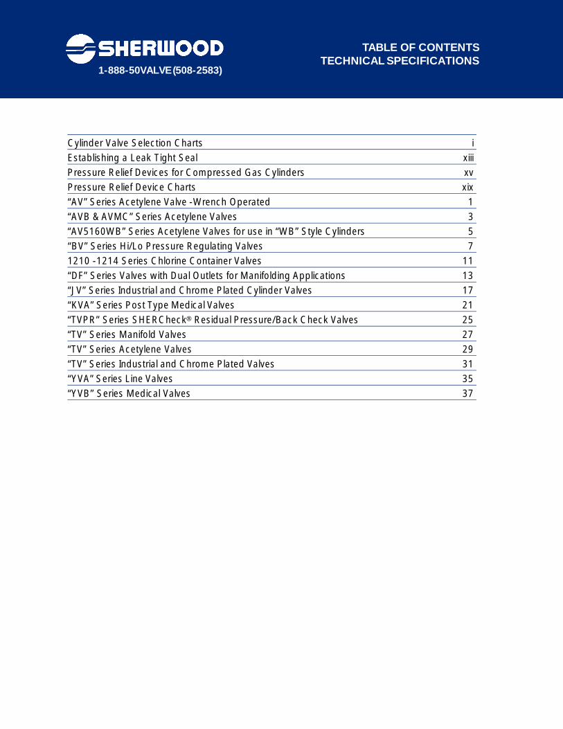
Cylinder Valve Selection Charts iEstablishing a Leak Tight Seal xiiiPressure Relief Devices for Compressed Gas Cylinders xvPressure Relief Device Charts xix“AV” Series Acetylene Valve -Wrench Operated 01“AVB & AVMC” Series Acetylene Valves 03“AV5160WB” Series Acetylene Valves for use in “WB” Style Cylinders 5“BV” Series Hi/Lo Pressure Regulating Valves 71210 -1214 Series Chlorine Container Valves 11“DF” Series Valves with Dual Outlets for Manifolding Applications 13“JV” Series Industrial and Chrome Plated Cylinder Valves 17“KVA” Series Post Type Medical Valves 21“TVPR” Series SHERCheck® Residual Pressure/Back Check Valves 25“TV” Series Manifold Valves 27“TV” Series Acetylene Valves 29“TV” Series Industrial and Chrome Plated Valves 31“YVA” Series Line Valves 35“YVB” Series Medical Valves 37
TABLE OF CONTENTS TECHNICAL SPECIFICATIONS
1-888-50VALVE (508-2583)
i
SHERWOOD CYLINDER VALVE SELECTION CHART
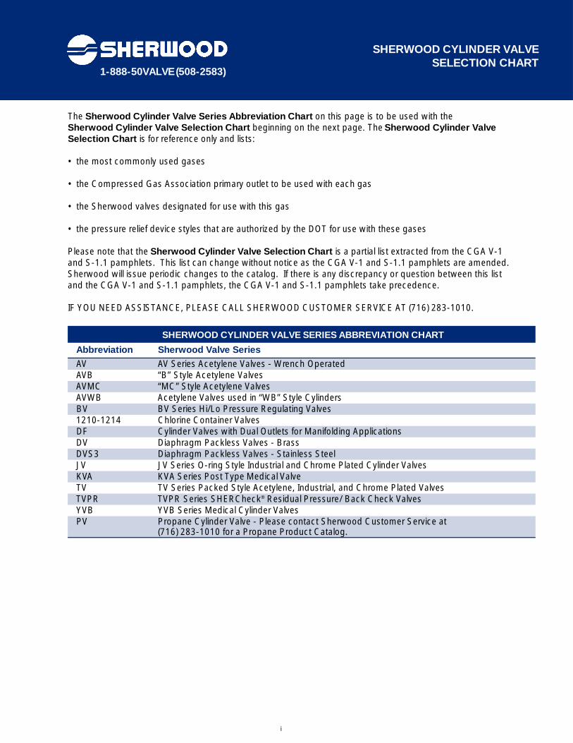
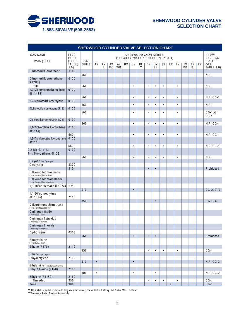
The Sherwood Cylinder Valve Series Abbreviation Chart on this page is to be used with the Sherwood Cylinder Valve Selection Chart beginning on the next page. The Sherwood Cylinder ValveSelection Chart is for reference only and lists:
• the most commonly used gases
• the Compressed Gas Association primary outlet to be used with each gas
• the Sherwood valves designated for use with this gas
• the pressure relief device styles that are authorized by the DOT for use with these gases
Please note that the Sherwood Cylinder Valve Selection Chart is a partial list extracted from the CGA V-1 and S-1.1 pamphlets. This list can change without notice as the CGA V-1 and S-1.1 pamphlets are amended.Sherwood will issue periodic changes to the catalog. If there is any discrepancy or question between this list and the CGA V-1 and S-1.1 pamphlets, the CGA V-1 and S-1.1 pamphlets take precedence.
IF YOU NEED ASSISTANCE, PLEASE CALL SHERWOOD CUSTOMER SERVICE AT (716) 283-1010.
SHERWOOD CYLINDER VALVE SERIES ABBREVIATION CHART
Abbreviation Sherwood Valve Series
AV AV Series Acetylene Valves - Wrench OperatedAVB “B” Style Acetylene ValvesAVMC “MC” Style Acetylene ValvesAVWB Acetylene Valves used in “WB” Style CylindersBV BV Series Hi/Lo Pressure Regulating Valves1210-1214 Chlorine Container ValvesDF Cylinder Valves with Dual Outlets for Manifolding ApplicationsDV Diaphragm Packless Valves - BrassDVS3 Diaphragm Packless Valves - Stainless Steel JV JV Series O-ring Style Industrial and Chrome Plated Cylinder ValvesKVA KVA Series Post Type Medical ValveTV TV Series Packed Style Acetylene, Industrial, and Chrome Plated ValvesTVPR TVPR Series SHERCheck® Residual Pressure/ Back Check ValvesYVB YVB Series Medical Cylinder ValvesPV Propane Cylinder Valve - Please contact Sherwood Customer Service at
(716) 283-1010 for a Propane Product Catalog.

1-888-50VALVE (508-2583)
iii
SHERWOOD CYLINDER VALVE SELECTION CHART
SHERWOOD CYLINDER VALVE SELECTION CHART
GAS NAME FTSC SHERWOOD VALVE SERIES PRD*** CODE (SEE ABBREVIATION CHART ON PAGE 1) PER CGA
PSIG (KPA) (SEE CGA S-1.1TABLE) OUTLET AV AV AV AV BV CV DF DV DV JV KV TV TV YV PV (SEE1.0) B MC WB ** S3 PR B TABLE 2.0)
Acetylene* 5130>50 cu.ft. (1.39 m3) 510 • • • CG-335-75 cu.ft. 520 • CG-3(970 L-2.08 m3)-10 cu.ft. (280 L) 200 • CG-3
Air (R729) 10600-3000 (0-20,680) 346 • • • • • • CG-1,-4,-5Threaded0-3000 (0-20,680) 950 • CG-1,-4Yoke3001-5500 347 • • • • • • CG-1,-4,-5(20,690-37,900)5501-7500 702 • • CG-1,-4,-5(38,000-51,700)
Allylene See Methylacetylene
Argon 10600-3000 (0-20,680) 580 • • • • • • CG-1,-4,-53001-5500 680 • • • CG-1,-4,-520,690-37,900)5501-7500(38,000-51,700) 677 • • • • CG-1,-4,-5
Arsine 2300350 • • Prohibited
Boron Fluoride See Boron Trifluoride
Boron Trifluoride 0263330 • • Prohibited
Bromine Pentafluoride 4303670 • • • • Prohibited
Bromine Trifluoride 0263670 • • • • Prohibited
Bromochlorodifluoromethane 0100(R12B1)
660 • • • • CG-1,-2,-3, -7
Bromoethylene See Vinyl Bromide
Bromomethane See Methyl Bromide
Bromotrifluoroethylene 3100(R113B1)
510 • • CG-1Bromotrifluoromethane 0100(R13B1)
660 • • • • CG-1,-7Butane (R600) 2100
Gas Withdrawal 510 • CG-7Liquid Withdrawal 555 • CG-7
1-Butene 2100510 • CG-7
2-Butene 2100510 • CG-7
-Butylene See 1-Butene
-Butylene See 2-Butene
1-Butyne See Ethylacetylene
Carbon Dioxide (R744) 0110Threaded 320 • • • • CG-1,-4Yoke 940 • CG-1
Carbonic Acid See Carbon Dioxide
Carbon Monoxide 2260350 • • • • •
* Acetylene is the only gas in this table that is not specified by gas pressure, it is specified by volumeteric units.** DF Valves can be used with all gases, however, the outlet will always be 1/4-27NPT female.***Pressure Relief Device Assembly.
1-888-50VALVE (508-2583)
iv
SHERWOOD CYLINDER VALVE SELECTION CHART
SHERWOOD CYLINDER VALVE SELECTION CHART
GAS NAME FTSC SHERWOOD VALVE SERIES PRD*** CODE (SEE ABBREVIATION CHART ON PAGE 1) PER CGA
PSIG (KPA) (SEE CGA S-1.1TABLE) OUTLET AV AV AV AV BV CV DF DV DV JV KV TV TV YV PV (SEE1.0) B MC WB ** S3 PR B TABLE 2.0)
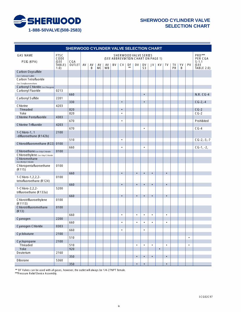
Carbon Oxysulfide See Carbonyl Sulfide
Carbon Tetrafluoride See Tetrafluoromethane
Carbonyl Chloride See Phosgene
Carbonyl Fluoride 0213660 • N.R. CG-4
Carbonyl Sulfide 2201330 • • CG-2,-4
Chlorine 4203Threaded 820 • CG-2Yoke 820 • CG-2
Chlorine Pentafluoride 4303670 • Prohibited
Chlorine Trifluoride 4203670 • CG-4
1-Chloro-1, 1 2100-difluoroethane (R142b)
510 • CG-2,-3,-7Chlorodifluoromethane (R22) 0100
660 • • CG-1, -2, Chloroethane See Ethyl Chloride 0100Chloroethylene See Vinyl Chloride
Chloromethane See Methyl Chloride
Chloropentafluoroethane 0100(R115)
660 • • • • •1-Chloro-1,2,2,2- 0100tetrafluoroethane (R124)
660 • • • • •1-Chloro-2,2,2- 5200trifluoroethane (R133a)
660 • • • • •Chlorotrifluoroethylene 0100(R1113)Chlorotrifluoromethane 0100(R13)
660 • • • • •Cyanogen 2200
660 • • • • •Cyanogen Chloride 0303
660 • •Cyclobutune 2100
510 •Cyclopropane 2100
Threaded 510 • • • • •Yoke 920 •
Deuterium 2160350 • • • •
Diborane 5360350 • • •
** DF Valves can be used with all gases, however, the outlet will always be 1/4-27NPT female.***Pressure Relief Device Assembly.
I-CG02C97
v
SHERWOOD CYLINDER VALVE SELECTION CHART
SHERWOOD CYLINDER VALVE SELECTION CHART
GAS NAME FTSC SHERWOOD VALVE SERIES PRD*** CODE (SEE ABBREVIATION CHART ON PAGE 1) PER CGA
PSIG (KPA) (SEE CGA S-1.1TABLE) OUTLET AV AV AV AV BV CV DF DV DV JV KV TV TV YV PV (SEE1.0) B MC WB ** S3 PR B TABLE 2.0)
Dibromodifluoroethane 1100660 N.R.
Dibromodifluoromethane 0100R12B2)
0100 660 • • • • • N.R.1,2-Dibromotetrafluoroethane 0100(R114B2)
660 • • • • • N.R. CG-11,2-Dichlorodifluoroethylene 0100
660 • • • • • N.R.Dichlorodifluoromethane (R12) 0100
660 • • • • • CG-1,-2,-3,-7
Dichlorofluoromethane (R21) 0100660 • • • • • N.R. CG-1
1 , 1 - D i c h l o ro t e t r a f l u o ro re t h a n e 0100(R114a)
660 • • • • • N.R. CG-11 , 2 -D i c h l o ro t e t r a f l u o ro e t h a n e 0100(R114)
660 • • • • • N.R. CG-12,2-Dichloro-1,1, 01001- trifluoroethane (R123)
660 • • • • • N.R.Dicyane See Cyanogen
Diethylzinc 3300510 • • Prohibited
Difluorodibromoethane See Dibromodifluoroethane
Difluorodibromomethane See Dibromodifluoromethane
1,1-Difluoroethane (R152a) N/A510 • CG-2,-3,-7
1,1-Difluoroethylene (R1132a) 2110
350 • CG-1,-4Difluoromonochlorethane See Chlorodifluoroethane
Dinitrogen Oxide See Nitrous Oxide
Dinitrogen Tetroxide See Nitrogen Dioxide
Dinitrogen Trioxide See Nitrogen Trioxide
Diphosgene 0303660 • • • Prohibited
EpoxyethaneSee Ethylene Oxide
Ethane (R170) 2110350 • • • • CG-1
Ethene See Ethylene
Ethyacetylene 2100510 • • N.R. CG-2
Ethylamine See Monoethylamine
Ethyl Chloride (R160) 2100300 • • • N.R. CG-2
Ethylene (R1150) 2160Threaded 350 • • • • CG-1
Yoke 900 • CG-1
** DF Valves can be used with all gases, however, the outlet will always be 1/4-27NPT female.***Pressure Relief Device Assembly.
1-888-50VALVE (508-2583)
1-888-50VALVE (508-2583)
vi
SHERWOOD CYLINDER VALVE SELECTION CHART
SHERWOOD CYLINDER VALVE SELECTION CHART
GAS NAME FTSC SHERWOOD VALVE SERIES PRD***CODE (SEE ABBREVIATION CHART ON PAGE 1) PER CGA
PSIG (KPA) (SEE CGA S-1.1TABLE) OUTLET AV AV AV AV BV CV DF DV DV JV KV TV TV YV PV (SEE1.0) B MC WB ** S3 PR B TABLE 2.0)
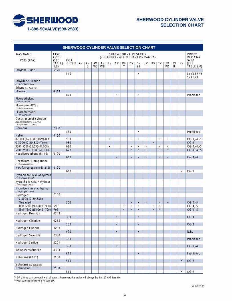
Ethylene Oxide 5120510 • See CFR49
173.323Ethylidene Fluoride See 1,1-Difluoroethane
Ethyne See Acetylene
Fluorine 4343679 • • Prohibited
Fluoroethylene See Vinyl Fluoride
Fluoroform (R23) See Trifluoromethane
Fluoromethane See Methyl Fluoride
Gases in small cylinders (See “Introduction” Par. 2.10 inCGA pamphlet V-1-1994)
Germane 2300350 • Prohibited
Helium 01600-3000 (0-20,680) Threaded 580 • • • • • • CG-1,-4,-50-3000 (0-20,680) Yoke 930 • CG-43001-5500 (20,690-37,900) 680 • • • • • • CG-1,-4,-55501-7500 (38,000-51,700) 677 • • • • • CG-1,-4,-5Hexafluoroethane (R116) 0100
660 • • • • • • CG-1,-4Hexafluoro-2-propanone See Hexafluoroacetone
Hexafluoropropylene (R1216) 0100660 • CG-1
Hydrobromic Acid, Anhydrous See Hydrogen Bromide
Hydrochloric Acid, Anhydrous See Hydrogen Chloride
Hydrofluoric Acid, Anhydrous See Hydrogen Fluoride
Hydrogen 2160
0-3000 (0-20,680) Threaded 350 • • • • • CG-4,-53001-5500 (20,690-37,900) 695 • • • • • CG-4,-55501-7500 (38,000-51,700) 703 • • • • • CG-4,-5
Hydrogen Bromide 0203330 • • CG-4
Hydrogen Chloride 0213330 • • CG-4
Hydrogen Fluoride 0203670 • • N.R.
Hydrogen Selenide 2300350 Prohibited
Hydrogen Sulfide 2201330 • CG-2,-4
Iodine Pentafluoride 4303670 • Prohibited
Isobutane (R601) 2100510 • CG-7
Isobutene See Isobutylene
Isobutylene 2100510 • CG-7
** DF Valves can be used with all gases, however, the outlet will always be 1/4-27NPT female.***Pressure Relief Device Assembly.
I-CG02C97
1-888-50VALVE (508-2583)
vii
SHERWOOD CYLINDER VALVE SELECTION CHART
SHERWOOD CYLINDER VALVE SELECTION CHART
GAS NAME FTSC SHERWOOD VALVE SERIES PRD***CODE (SEE ABBREVIATION CHART ON PAGE 1) PER CGA
PSIG (KPA) (SEE CGA S-1.1TABLE) OUTLET AV AV AV AV BV CV DF DV DV JV KV TV TV YV PV (SEE1.0) B MC WB ** S3 PR B TABLE 2.0)
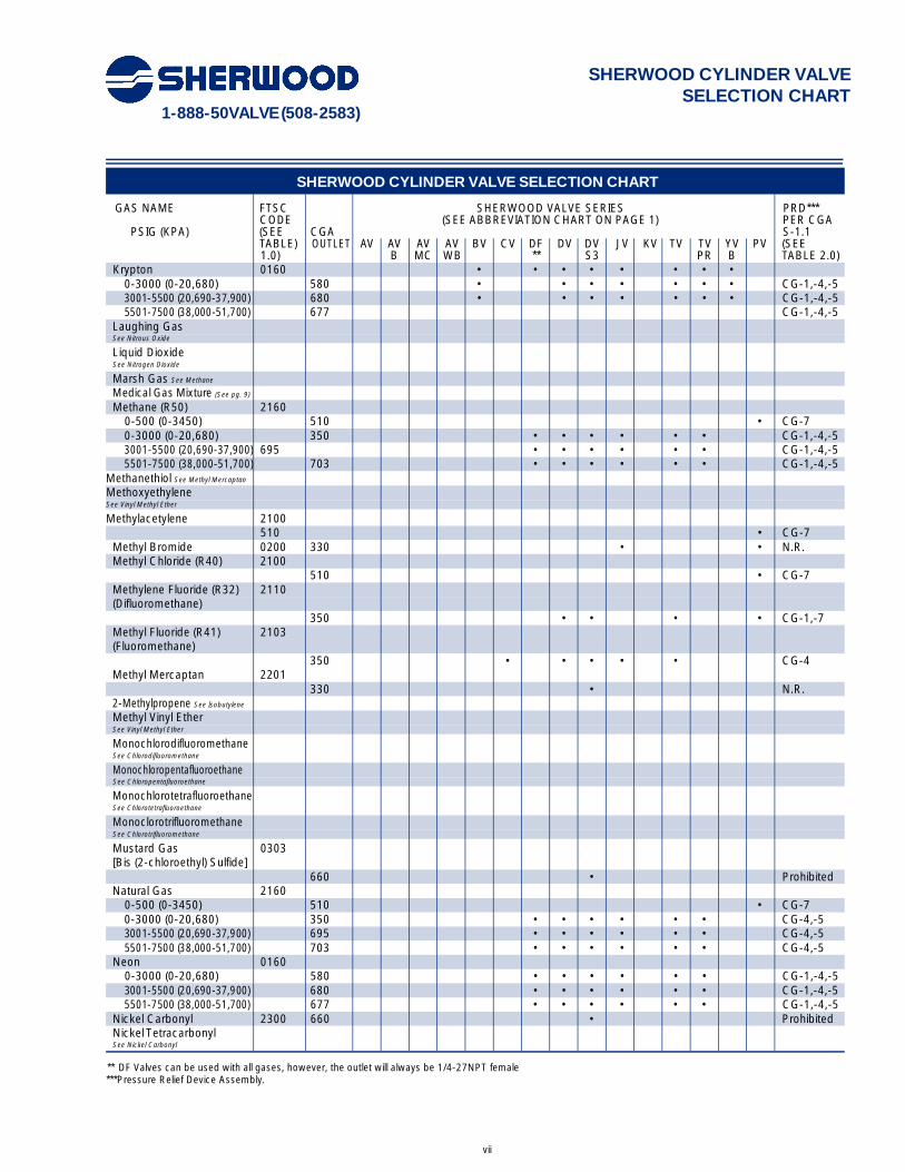
Krypton 0160 • • • • • • • •0-3000 (0-20,680) 580 • • • • • • • CG-1,-4,-53001-5500 (20,690-37,900) 680 • • • • • • • CG-1,-4,-55501-7500 (38,000-51,700) 677 CG-1,-4,-5
Laughing Gas See Nitrous Oxide
Liquid Dioxide See Nitrogen Dioxide
Marsh Gas See Methane
Medical Gas Mixture (See pg. 9)
Methane (R50) 21600-500 (0-3450) 510 • CG-70-3000 (0-20,680) 350 • • • • • • CG-1,-4,-53001-5500 (20,690-37,900) 695 • • • • • • CG-1,-4,-55501-7500 (38,000-51,700) 703 • • • • • • CG-1,-4,-5
Methanethiol See Methyl Mercaptan
Methoxyethylene See Vinyl Methyl Ether
Methylacetylene 2100510 • CG-7
Methyl Bromide 0200 330 • • N.R.Methyl Chloride (R40) 2100
510 • CG-7Methylene Fluoride (R32) 2110(Difluoromethane)
350 • • • • CG-1,-7Methyl Fluoride (R41) 2103(Fluoromethane)
350 • • • • • CG-4Methyl Mercaptan 2201
330 • N.R.2-Methylpropene See Isobutylene
Methyl Vinyl Ether See Vinyl Methyl Ether
MonochlorodifluoromethaneSee Chlorodifluoromethane
MonochloropentafluoroethaneSee Chloropentafluoroethane
MonochlorotetrafluoroethaneSee Chlorotetrafluoroethane
MonoclorotrifluoromethaneSee Chlorotrifluoromethane
Mustard Gas 0303[Bis (2-chloroethyl) Sulfide]
660 • ProhibitedNatural Gas 2160
0-500 (0-3450) 510 • CG-70-3000 (0-20,680) 350 • • • • • • CG-4,-53001-5500 (20,690-37,900) 695 • • • • • • CG-4,-55501-7500 (38,000-51,700) 703 • • • • • • CG-4,-5
Neon 01600-3000 (0-20,680) 580 • • • • • • CG-1,-4,-53001-5500 (20,690-37,900) 680 • • • • • • CG-1,-4,-55501-7500 (38,000-51,700) 677 • • • • • • CG-1,-4,-5
Nickel Carbonyl 2300 660 • ProhibitedNickel Tetracarbonyl See Nickel Carbonyl
** DF Valves can be used with all gases, however, the outlet will always be 1/4-27NPT female***Pressure Relief Device Assembly.

1-888-50VALVE (508-2583)
viii
SHERWOOD CYLINDER VALVE SELECTION CHART
SHERWOOD CYLINDER VALVE SELECTION CHART
GAS NAME FTSC SHERWOOD VALVE SERIES PRD***CODE (SEE ABBREVIATION CHART ON PAGE 1) PER CGA
PSIG (KPA) (SEE CGA S-1.1TABLE) OUTLET AV AV AV AV BV CV DF DV DV JV KV TV TV YV PV (SEE1.0) B MC WB ** S3 PR B TABLE 2.0)
Nitric Oxide 4361660 • Prohibited
Nitrogen 01600-3000 (0-20,680) Threaded 580 • • • • • • CG-1,-4,-50-3000 (0-20,680) Yoke 960 • CG-1,-4,-5Oil Tolerant 621 • • • • • • CG-1,-4,-53001-5500 (20,690-37,900) 680 • • • • • • CG-1,-4,-55501-7500 (38,000-51,700) 677 • • • • • • CG-1,-4,-5Nitrogen Dioxide 4301
660 • ProhibitedNitrogen Peroxide See Nitrogen Dioxide
Nitrogen Sesquioxide See Nitrogen Trioxide
Nitrogen Tetroxide See Nitrogen Dioxide
Nitrogen Trifluoride 4140670 • • • CG-3,-4,-5
Nitrogen Trioxide N.A.660 • CG-3,-4,-5
Nitrous Oxide (R744a) 4110Threaded 326 • • • • • CG-1Yoke 910 • CG-1
Octafluorocyclobutane (RC318) 0100660 • CG-7
Octafluoropropane (R218) 0100660 • • • • • CG-1,-7
Oxirane See Ethylene Oxide
Oxygen 40600-3000 (0-20,680) 540 • • • • • • CG-1,-4,-5Threaded0-3000 (0-20,680) 870 • CG-1,-4,-5Yoke3001-5500 577 • • • • • CG-1,-4, -5(20,690-37,900)5501-7500 701 • • • • • CG-1,-4,-5(38,000-51,700)
Oxygen Difluoride 4343679 • • Prohibited
Pentaborane 3300350 • • Prohibited
Pentafluoroethane 0100(HFC-125)
660 • • • • • CG-1,-7P e rf l u o robutane (FC-3-1-10) 0100(R-610)
660 • • • • • • N.R. CG-2,-7
Perfluor-2-butene 0100660 • • • • • N.R. CG-2
Perfluorocyclobutane See Octafluorocyclobutane
Perfluoroethane See Hexafluoroethane
Perfluoropropane See Octafluoropropane
Phosgene 0303660 • • • Prohibited
Phosphine 3310350 • • • Prohibited
** DF Valves can be used with all gases, however, the outlet will always be 1/4-27NPT female.***Pressure Relief Device Assembly.
1-888-50VALVE (508-2583)
ix
SHERWOOD CYLINDER VALVE SELECTION CHART
SHERWOOD CYLINDER VALVE SELECTION CHART
GAS NAME FTSC SHERWOOD VALVE SERIES PRD***CODE (SEE ABBREVIATION CHART ON PAGE 1) PER CGA
PSIG (KPA) (SEE CGA S-1.1TABLE) OUTLET AV AV AV AV BV CV DF DV DV JV KV TV TV YV PV (SEE1.0) B MC WB ** S3 PR B TABLE 2.0)
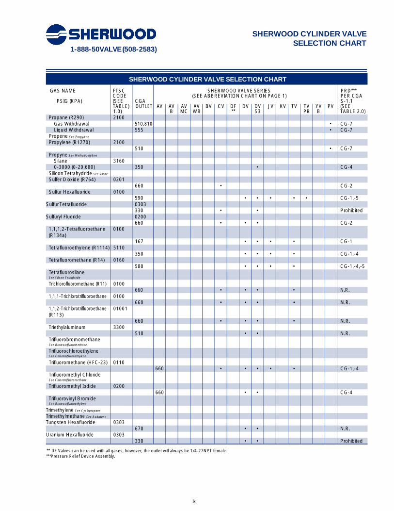
Propane (R290) 2100Gas Withdrawal 510,810 • CG-7Liquid Withdrawal 555 • CG-7
Propene See Propylene
Propylene (R1270) 2100510 • CG-7
Propyne See Methylacetylene
Silane 31600-3000 (0-20,680) 350 • CG-4
Silicon Tetrahydride See Silane
Sulfer Dioxide (R764) 0201660 • CG-2
Sulfur Hexafluoride 0100590 • • • • • CG-1,-5
Sulfur Tetrafluoride 0303330 • • Prohibited
Sulfuryl Fluoride 0200660 • • • CG-2
1,1,1,2-Tetrafluoroethane 0100(R134a)
167 • • • • CG-1Tetrafluoroethylene (R1114) 5110
350 • • • • CG-1,-4Tetrafluoromethane (R14) 0160
580 • • • • CG-1,-4,-5Tetrafluorosilane See Silicon Tetrafloride
Trichlorofluoromethane (R11) 0100660 • • • • N.R.
1,1,1-Trichlorotrifluoroethane 0100660 • • • • N.R.
1,1,2-Trichlorotrifluoroethane 01001(R113)
660 • • • • N.R.Triethylaluminum 3300
510 • • N.R.Trifluorobromomethane See Bromotrifluoromethane
Trifluorochloroethylene See Chlorotrifluoroethylene
Trifluoromethane (HFC-23) 0110660 • • • • • CG-1,-4
Trifluoromethyl Chloride See Chlorotrifluoromethane
Trifluoromethyl Iodide 0200660 • • CG-4
Trifluorovinyl Bromide See Bromotrifluoroethylene
Trimethylene See Cyclopropane
Trimethylmethane See Isobutane
Tungsten Hexafluoride 0303670 • • N.R.
Uranium Hexafluoride 0303330 • • Prohibited
** DF Valves can be used with all gases, however, the outlet will always be 1/4-27NPT female.***Pressure Relief Device Assembly.

1-888-50VALVE (508-2583)
x
SHERWOOD CYLINDER VALVE SELECTION CHART
SHERWOOD CYLINDER VALVE SELECTION CHART
GAS NAME FTSC SHERWOOD VALVE SERIES PRD***CODE (SEE ABBREVIATION CHART ON PAGE 1) PER CGA
PSIG (KPA) (SEE CGA S-1.1TABLE) OUTLET AV AV AV AV BV CV DF DV DV JV KV TV TV YV PV (SEE1.0) B MC WB ** S3 PR B TABLE 2.0)
Vinyl Bromide 5100510 • N.R. CG-2
Vinyl Chloride (R1140) 5100510 • CG-2
Vinyl Fluoride (R1141) 2100350 • CG-4
Vinylidene Fluoride See 1,1-Difluoroethylene
Vinyl Methyl Ether 5100510 • CG-2
Xenon 01600-3000 (0-20,680) 580 • • • • • • CG-1,-43001-5500 (20,690-37,900) 680 • • • • • • CG-1, -45501-7500 677 • • • • • CG-1,-4(38,000-51,700)
MEDICAL ➀ GAS MIXTURES ➁ ➂ FOR PRESSURES UP TO 3000 (20,680)
Carbon Dioxide & Oxygen(CO2 not over 7%)
Threaded 280 • • CG-1,-4Yoke 880 • CG-1,-4
Carbon Dioxide & Oxygen (CO2 over 7%)
Threaded 500 • • CG-1,-4Yoke 940 • CG-1,-4
Carbon Dioxide,Oxygen, Nitrogen
Threaded 500 • • CG-1,-4Yoke 973 • CG-1,-4
Clinical Blood Gas MixturesThreaded 500 • • CG-1,-4Yoke 973 • CG-1,-4
Gas Mixtures, Medical➀➂ Flammable
Threaded 350 • • CG-4Yoke 981 • CG-4
Gas Mixtures, Medical➀➂➃,Nonflammable, Noncorrosive
Threaded 500 • • CG-1,-4Yoke 973 • CG-1,-4
Gas Mixtures, Medical➀➂➃,Nonflammable, Noncorrosive
Threaded 580 • • CG-1,-4Yoke 985 • CG-1,-4
Helium & Oxygen (He not over 80%)
Threaded 280 • • CG-1,-4Yoke 890 • CG-1,-4
Helium & Oxygen (He over 80%)Threaded 500 • • CG-1,-4Yoke 930 • CG-1,-4
Lung Diffusion MixturesThreaded 500 • • CG-1,-4Yoke 973 • CG-1,-4
Nitric Oxide MixturesThreaded 626 • Prohibited
** DF Valves can be used with all gases, however, the outlet will always be 1/4-27NPT female.***Pressure Relief Device Assembly.➀ For a definition of the term Medical Gas see paragraph 6 page 11 of the Introduction CGA pamphlet V-1-1994. ➁ Nominal mixture concentration; normal mixturetolerances are allowable. ➂ Gas Mixtures labeled as drugs or medical devices and not having another connection assigment.➃ For specific gas assigments see the reference connection number in CGA pamphlet V-1-1994.

1-888-50VALVE (508-2583)
xi
SHERWOOD CYLINDER VALVE SELECTION CHART
SHERWOOD CYLINDER VALVE SELECTION CHART
GAS NAME FTSC SHERWOOD VALVE SERIES PRD***CODE (SEE ABBREVIATION CHART ON PAGE 1) PER CGA
PSIG (KPA) (SEE CGA S-1.1TABLE) OUTLET AV AV AV AV BV CV DF DV DV JV KV TV TV YV PV (SEE1.0) B MC WB ** S3 PR B TABLE 2.0)
MEDICAL ➁ GAS MIXTURES ➁ ➂ FOR PRESSURES UP TO 3000 (20,680)ˆ
Nitric Oxide Mixtures and Nitrogen Dioxide Mixtures
Threaded 625 • ProhibitedNitrous Oxide & Oxygen (N2 47.5 to 52.5%)
Threaded 280 • • CG-1,-4Yoke 965 • CG-1,-4
Nitrogen & Oxygen (O2 over 23.5%)
Threaded 280 • • CG-1,-4Yoke 890 • CG-1,-4
Oxidizing MixturesThreaded 296 • • CG-1,-4Yoke 977 • CG-1,-4Xenon & Oxygen (O2 over 20%)Threaded 280 • • CG-1,-4Yoke 890 • CG-1,-4
** DF Valves can be used with all gases, however, the outlet will always be 1/4-27NPT female.***Pressure Relief Device Assembly.• For a definition of the term Medical Gas see paragraph 6 page 11 of the Introduction CGA pamphlet V-1-1994.• Nominal mixture concentration; normal mixture tolerances are allowable.• Gas Mixtures labeled as drugs or medical devices and not having another connection assigment.• For specific gas assigments see the reference connection number in CGA pamphlet V-1-1994
TABLE 2.0 TYPES OF PRESSURE RELIEF DEVICES
TYPE DESCRIPTION
CG-1 Rupture DiscCG-2 165°F (73.9°C) Fusible Plug for Cylinder Product not exceeding 500 psig (3450 KPa)CG-3 212°F (100°C) Fusible Plug for Cylinder Product not exceeding 500 psig (3450 KPa)CG-4 Rupture Disc with 165°F (73.9°C) Fusible Alloy BackingCG-5 Rupture Disc with 212°F (100°C) Fusible Alloy BackingCG-7 Pressure Relief ValveCG-8 Rupture Disc Followed by (in Series) a Pressure Relief ValveCG-9 217°F (102.7°C) Fusible Plug for Cylinder Marked Service Pressure not
exceeding 6000 psig (41400 KPa)Prohibited Prohibited from using a Pressure Relief Device for this gas by 49CFR100-199N.R. None Required
N.R. CG-__ None Required, but if a Pressure Relief Device is to be used the CG-_ style is to be selected
1-888-50VALVE (508-2583)
xii
SHERWOOD CYLINDER VALVE SELECTION CHART
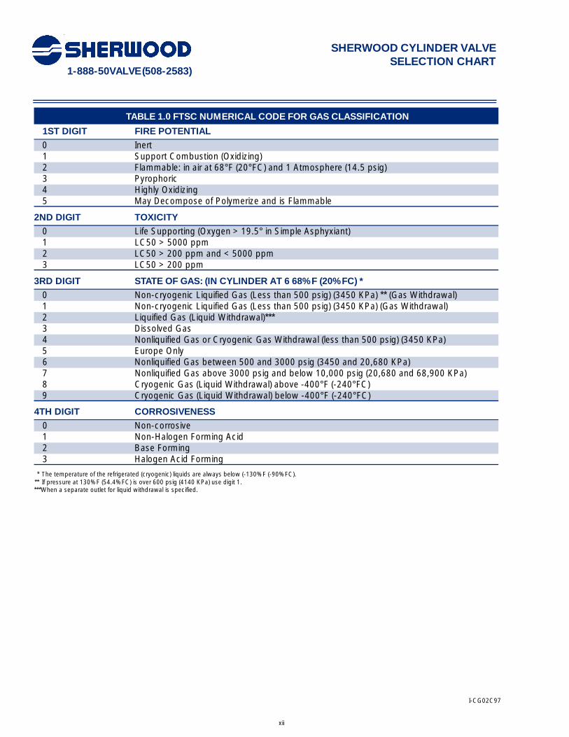
TABLE 1.0 FTSC NUMERICAL CODE FOR GAS CLASSIFICATION
1ST DIGIT FIRE POTENTIAL
0 Inert1 Support Combustion (Oxidizing)2 Flammable: in air at 68°F (20°FC) and 1 Atmosphere (14.5 psig)3 Pyrophoric4 Highly Oxidizing5 May Decompose of Polymerize and is Flammable
2ND DIGIT TOXICITY
0 Life Supporting (Oxygen > 19.5° in Simple Asphyxiant)1 LC50 > 5000 ppm2 LC50 > 200 ppm and < 5000 ppm3 LC50 > 200 ppm
3RD DIGIT STATE OF GAS: (IN CYLINDER AT 6 68%F (20%FC) *
0 Non-cryogenic Liquified Gas (Less than 500 psig) (3450 KPa) ** (Gas Withdrawal)1 Non-cryogenic Liquified Gas (Less than 500 psig) (3450 KPa) (Gas Withdrawal)2 Liquified Gas (Liquid Withdrawal)***3 Dissolved Gas4 Nonliquified Gas or Cryogenic Gas Withdrawal (less than 500 psig) (3450 KPa)5 Europe Only6 Nonliquified Gas between 500 and 3000 psig (3450 and 20,680 KPa)7 Nonliquified Gas above 3000 psig and below 10,000 psig (20,680 and 68,900 KPa)8 Cryogenic Gas (Liquid Withdrawal) above -400°F (-240°FC)9 Cryogenic Gas (Liquid Withdrawal) below -400°F (-240°FC)
4TH DIGIT CORROSIVENESS
0 Non-corrosive1 Non-Halogen Forming Acid2 Base Forming3 Halogen Acid Forming
* The temperature of the refrigerated (cryogenic) liquids are always below (-130%F (-90%FC).** If pressure at 130%F (54.4%FC) is over 600 psig (4140 KPa) use digit 1.***When a separate outlet for liquid withdrawal is specified.
I-CG02C97

1-888-50VALVE (508-2583)
xiii
ESTABLISHING A LEAK TIGHT SEAL
Cylinder Valve Inlet ConnectionsThis section summarizes the uniform American andCanadian standards for cylinder valve inlet connectionsin which a threaded joint is used to attach cylindervalves to cylinders and containers. A more complete dis-cussion may be found in CGA V-1.*
Two basic types of threads are used: (1) straightthread and (2) tapered thread. The straight threadrequires use of an O-ring or gasket to accomplish agastight seal. This type of thread requires lessinstallation torque than a tapered thread and is mostlyused with aluminum cylinders. Common sizes currentlyin use are 0.750-16UNF and 1.125-12UNF. In mostcommon use are the national gas tapered (NGT) threadswith a taper rate of 3⁄4 inch per foot. Most NGT cylindervalve inlet connections are 3⁄4-14NGT, where 3⁄4 is thenominal size of the thread in inches and 14 is thenumber of threads per inch. Other popular sizes are 3⁄8-18NGT, 1⁄2-14 NGT, and 1-11 1⁄2- NGT.
Oversized ThreadsOversize NGT threads are also available; four and seventhreads oversize are the most common. The availabilityof oversize threads on valves prolongs the life ofcylinders by compensating for the wear that occurs tocylinder threads from repeated valving operations.
Uniquely, chlorine valves have their own oversize thread series: 0 threads oversize [3⁄4-14NGT (Cl)-1]4 threads oversize [3⁄4-14NGT (Cl)-2]8 1⁄2 threads oversize [3⁄4-14NGT (Cl)-3]14 threads oversize [3⁄4-14NGT (Cl)-4]28 threads oversize [3⁄4-14NGT (Cl)-5]
The (Cl) designation signifies chlorine.
Establishing a Leak-Tight SealA leak-tight seal can be established using the “hand-tight plus three turns for wrenching” method. Hand-tightengagement occurs when the pitch diameter of the firstthread on the valve engages the thread in the cylinderneck with the same pitch diameter. For any new 3⁄4-14NGT thread, mating hand-tight engagement occursnominally after an engagement of 0.339 inch or, 0.339inch x 14 threads/inch = approximately 4 3⁄4 threads. (Todetermine the hand-tight engagement dimension forother types of threads, please refer to CGA V-1-1994)
A manufacturing tolerance of plus or minus one turn ispermitted on both the valve and the cylinder threads.
Therefore, hand-tight engagement can be approximately2 3⁄4 to 6 3⁄4 threads, when oversize and undersizethread tolerance limits are taken into consideration.
Three turns are then allowed for wrenching toestablish a leak-tight seal. Thus, total engaged threadscan range from 5 3⁄4 to 9 3⁄4 full threads.
Since the length of full threads on a 3⁄4-14NGT valve is 0.7676 inch (this dimension has been obtained fromCGA V-1-1994, the total number of full threads is0.7676 inch x 14 threads/inch, or approximately 10 3⁄4threads. If the thread tolerances are such that the valvethreads are as large as they can be and the cylinderopening is as small as it can be, the valve enters only 23⁄4 turns for hand-tight engagement. That is, if the largestvalve is installed in the smallest cylinder, there will beapproximately five full threads showing after the threeturns for wrenching (2 3⁄4 plus 3 turns for wrenchingminus a total of 10 3⁄4 threads on valve inlet.)
Conversely, if the thread tolerances are such that thevalve threads are as small as they can be and the cylin-der opening is as large as it can be, the valve will enter 63⁄4 turns for hand-tight engagement. Thus, if the smallestvalve is installed in the largest cylinder, there will beapproximately one full thread showing, after the threeturns for wrenching. While it is highly improbable thatthese extremes will be experienced with new parts, thisillustrates why the counting of exposed threads is a poorway of ascertaining a sufficiently engaged joint.
Using a predetermined amount of torque to establisha leak-tight seal also has some drawbacks. Variations incoefficients of friction, thread damage, type of sealantused, and so on, can influence the amount of appliedtorque that is necessary to create a seal. For example, ifthe first thread on the cylinder valve is damaged, muchof the torque may be used just to overcome theresistance of the damaged thread.
The “hand-tight plus 3 turns for wrenching” identifiedin both CGA V-1 and NBS Handbook H28, FederalScrew Thread Standards, provides a method for engag-ing the valve to a steel cylinder that is not affected bymanufacturing tolerances on the valve and cylinderthreads (for aluminum cylinders and/or straight threads,consult the manufacturer.)
However, the number of turns required to establish ahand-tight engagement will vary depending on whetherthe threaded joint is bare metal, whether Teflon® tape isapplied to the valve, or whether a suitable lutingcompound is used.
One way to compensate for the above mentionedvariables is to first tighten the joint without luting
1-888-50VALVE (508-2583)
xiv
ESTABLISHING A LEAK TIGHT SEAL
compound or Teflon® tape as tight as possible withgloved hands, and count the turns needed toaccomplish this. Next, apply the luting compound orTeflon® tape that is going to be used in actual valveinstallations and repeat the above hand-tightening pro-cedure, again counting turns. The difference betweenthe number of turns to accomplish a hand- tight jointwith and without luting compound (or Teflon® tape)should then be added to the “3 turns for wrenching.”
For example, consider the instance where 5 turns areneeded to make a hand-tight engagement with baremetal. When luting compound or Teflon® tape is used forthis same valve, 4 1⁄2 turns are required to arrive at ahand-tight engagement. To establish a leak-tight seal,the valve would then be wrenched 3 1⁄2 turns rather than3, or engaged a total of 8 1⁄2 turns. That is, 5 turns (baremetal hand-tight) plus 3 1⁄2 turns (3 for wrenching plus 1⁄2from tape). In this manner, the effect of the tape or lutingcompound is adequately taken into account.
Other valve installation methods are successfullyused, but all of them, when properly done, end up withapproximately the same number of wrenched turns.
*For further information on cylinder valve inlet connections and other threadtypes presently in use, that is, Special Gas Taper Threads (SGT) and NationalGas Straight Threads (NGS), refer to CGA V-1, American National, Canadian,and Compressed Gas Association Standard for Compressed Gas Cylinder ValveOutlet and Inlet Connections.
I-CG02A97
1-888-50VALVE (508-2583)
xv
PRESSURE RELIEF DEVICES FORCOMPRESSED GAS CYLINDERS
I n t ro d u c t i o nAlmost all compressed gas containers are fitted withpressure relief devices. A pressure relief device is a pres-sure- and/or temperature-activated device used to pre-vent the pressure from rising above a predeterminedmaximum, and thereby prevent rupture of a normallycharged cylinder when subjected to a standard fire testas required by Title 49 of the U.S. Code of FederalRegulations (49 CFR 173.34(d)), or equivalentregulations of Transport Canada.
P re s s u re Relief and Safety DevicesThe Compressed Gas Association, in pamphlet CGA S-1.1, has classified pressure relief devices according totype using the letter designation CG followed by anumeral. Each of these types is described in the follow-ing subsections (reference CGA S-1.1).
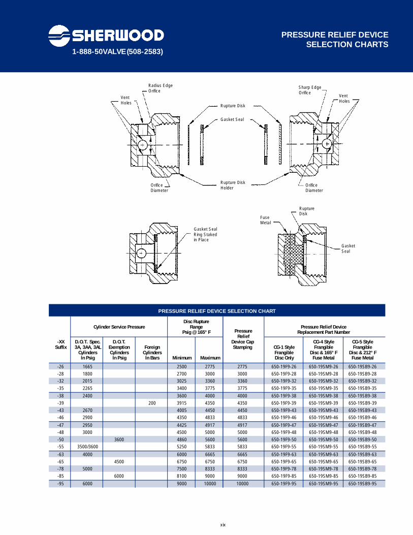
Type CG-1 (Pressure Relief Rupture Disk). A rupturedisk (synonymous with the name burst disk within theindustry) is a pressure-operated device which affordsprotection against development of excessive pressure incylinders. This device is designed to sense excess pres-sure in a cylinder and will function when the cylinderpressure is of sufficient magnitude to cause the ruptureor bursting of the rupture disk element, thereby ventingthe contents of the cylinder. The rupturing of the rupturedisk element results in a nonreclosing orifice.
Rupture disk devices installed on compressed gascylinders may be either an integral part of the cylindervalve assembly or may be installed on the cylinder as anindependent attachment. The materials of constructionselected must be compatible with the fluid in thecylinder as well as the cylinder valve materials withwhich the rupture disk device comes in contact in orderto minimize corrosion.
One of the most common types of rupture diskdevices consists of (1) a gasket, (2) a rupture disk, and(3) a rupture disk holder. These components are onlysupplied as factory-assembled devices designed to bereplaced as a unit.
The gasket is the part which provides the proper sealto prevent leakage of the cylinder contents past the rup-ture disk assembly and may be constructed of metallicor nonmetallic materials.
The rupture disk is the operating part of the pressurerelief device and, when installed in a proper rupture diskholder, is designed to burst at a predetermined pressureto permit discharge of the cylinder contents. Such disksare usually made of metallic materials and may be of flat,preformed, reinforced, grooved, or scored construction.Nonmetallic materials are also used for specific applica-tions.
The rupture disk holder is the part of the pressurerelief device which contains the opening, against whichthe rupture disk mates. The rupture disk holder usuallyalso contains the discharge porting or passages,beyond the operating parts of the device, through whichfluid must pass to reach the atmosphere. In manycases, the discharge holder is provided with radial ventholes through which the fluid in the cylinder vents to theatmosphere. This radial discharge design provides ananti-recoil feature which minimizes rocketing ofcompressed gas cylinders during discharge of the con-tents through the pressure relief device. Other types ofdischarge ports may also be provided in rupture diskholders to suit specific application requirements.
Most rupture disk devices are designed with holdershaving either sharp-edged or radius-edged orifices towhich the rupture disk mates. The sharp-edged orificeproduces a shear-type actuation mode whereby the diskruptures in shear, producing a characteristic leaf-typeconfiguration after functioning.
The radius-edged orifice produces a tension-typeactuation made whereby the disc stretches over theradius-edge. This thins the center of the disc until it canno longer hold the pressure. This type of ruptureproduces a characteristic rose petal configuration afterfunctioning.
Since the actuation modes of each type of holderdescribed above are completely different, it is importantthat only original manufacturer’s assemblies be used inthe replacement of rupture disk devices.

1-888-50VALVE (508-2583)
xvi
PRESSURE RELIEF DEVICES FORCOMPRESSED GAS CYLINDERS
The pressure relief rup-ture disk device is a pri-mary safety component
and hence the following precautions should be notedand adhered to:a) Only trained personnel should be permitted to ser-vice pressure relief devices.b) Tightening of the rupture disk assembly to thecylinder valve or to the cylinder itself should be inaccordance with the manufacturer’s instructions.Tightening to a torque less than the manufacturer’srecommendations may result in a leaking device or adevice that may rupture at a lower pressure thanspecified. Conversely, over tightening can also resultin disk actuation at a lower pressure than specifieddue to an excessive twisting action which may createwrinkles or distortions in the disk, which may causepremature failure of the disk and inadvertent releaseof the cylinder contents. Either of these prematurereleases could cause serious injury or death.
Components of devicesdesigned to rupture inshear are very simular in
appearance to those designed to rupture in tension,but are not interchangeable because they have com-pletely different modes of actuation. If componentsare inadvertently interchanged, i.e. a disk designed torupture in shear is installed in a rupture disk holderdesigned to rupture in tension, a serious cylinder fail-ure incident could result that could lead to loss of lifedue to the significant increase in pressure required torupture the disk. Conversely, if a disk designed torupture in tension is installed in a rupture disk holderdesigned to rupture in shear, premature rupture couldoccur with complete loss of contents due to the sig-nificant reduction in rupture pressure of the disk. Thatmay lead to fire, personal injury or death.
LIMITATIONS:A rupture disk is a pressure-operated device whichaffords protection against excessive pressure. It protectsagainst excessive pressure when the properties of thegas, cylinder design, and percentage of charge in thecylinder are such that exposure to excessively high tem-peratures will cause an increase in internal pressure suf-ficient to actuate the rupture disk before the cylinderloses its integrity and weakens. The rupture disk alsoprotects against excessive pressure due to impropercharging practices such as overfilling.
A rupture disk is a nonreclosing device. Once the diskhas ruptured, there is no way to prevent the completerelease of the contents of the cylinder.
This device does not provide good protection againstpressures caused by exposure to excessively high tem-peratures when the cylinder is only partially charged.The pressure rise may not be sufficient to actuate therupture disk before the cylinder loses its integrity andweakens.
Consideration should be given to environmental con-ditions to which the cylinder may be exposed. Severelycorrosive atmospheres may contribute to prematurerupture of the disk. To prevent corrosion of the rupturedisk, care must be taken to select materials of construc-tion that do not interact with either the contents of thecylinder or the anticipated environmental conditions.
Type CG-2 and CC-3 (Fusible Plugs). A fusible plugis a thermally-operated pressure relief device whichaffords protection against excessive pressure developedby exposure to excessive heat. Once sufficient heatmelts the fusible alloy, the entire contents of the cylinderwill be vented. The CG-2 fusible alloy has a nominal melttemperature of 165°F (73.9°C); the CG-3 fusible metalhas a nominal melt temperature of 212°F (I00°C).
Fusible plugs can be installed on the cylinder as inde-pendent devices, or fusible alloy can be cast directly intoa suitable orifice in the cylinder valve body. In somecases, a fusible plug may be installed as a separatedevice into the cylinder valve body.
I-CG02B97
1-888-50VALVE (508-2583)
xvii
PRESSURE RELIEF DEVICES FORCOMPRESSED GAS CYLINDERS
LIMITATIONS:Since the fusible plug is a thermally operateddevice, it is designed to function only when thefusible metal melts out. Hence, it does not protectagainst over pressure from improper charging prac-tices.
Sufficient heat to melt the fusible alloy isnecessary for proper functioning of this type ofdevice. Therefore, the location of such devices is animportant consideration.
Industry practice limits the application of thesestyle fusible plugs to cylinders with 500 psig (3447kPa) service pressure or less to minimize the possi-bility of cold flow or extrusion of the fusible alloy.
A fusible plug device is a nonreclosing device and,when it functions, it releases the entire contents ofthe cylinder.
Type CG-4 and CG-5 (Combination RuptureDisk/Fusible Plug). A combination rupture disk/ fusibleplug pressure relief device requires both excessive pres-sure and excessive temperature to cause it to operate.Sufficient heat is required to first melt out the fusiblemetal, after which the device will afford the sameprotection as the CG-1 rupture disk device.
The CG-4 combination device has fusible alloy with anominal melt temperature of 165°F (73.9°C). The CG- 5combination device has fusible alloy with a nominal melttemperature of 212°F (100°C).
In this type of device, the rupture disk portion (CG-1)is directly exposed to the internal cylinder pressure, andso it is directly upstream of the fusible metal. In general,the same components that make up the CG-1 deviceare used and the vent portion or downstream side of therupture disk holder is suitably filled with fusible metal.The rupture disk is thus reinforced against rupturing bythe fusible alloy, and the fusible alloy is reinforcedagainst extrusion by the rupture disk.
No attempt should bemade to repair fusibleplug devices. They are
not repairable and attempts to repair will destroy theintegrity of the fusible alloy causing leakage of gasesthat may lead to fire, personal injury or death. LIMITATIONS:
CG-4 and CG-5 combination devices function onlyin the presence of both excessive heat andexcessive pressure, and sufficient heat must be pre-sent first to melt the fusible metal.
Therefore, this device does not offer protectionagainst over pressure from improper charging prac-tices.
Type CG-7 (Pressure Relief Valves). A pressure reliefvalve is a spring-loaded pressure-operated devicedesigned to relieve excessive cylinder pressure, reclose,and reseal to prevent further release of product from thecylinder after excessive pressure is removed and valveresealing pressure has been achieved.
The primary advantage of using the pressure reliefvalve is that functioning of this type of device may notrelease all of the contents of the cylinder, but is designedto reseal after resealing pressure has been achieved.This characteristic, in fire conditions, will minimize feed-ing the fire in the case of flammable or combustiblecylinder contents.
LIMITATIONS:Pressure relief valves are designed to maintain thepressure in the cylinder at a limit as determined bythe spring force. Therefore, such devices do notprotect the cylinder against possible rupture whencontinued application of external heat or directflame impingement weakens the cylinder wall to thepoint where its rupture pressure is less than theoperating pressure of the relief valve.
If you require any assistance in selecting a PressureRelief or Safety device for a specific application, pleasecall Sherwood Customer Service at (716) 283-1010 withthe following information:• The part number of the Valve Assembly beingrepaired, if applicable.• Type of gas service in which cylinder will be used.• Service or test pressure of the cylinder.
NOTE: The same precautions noted for CG-1devices should be adhered to for CG-4 and CG-5devices. See “Warning’s” on pages 1 and 2.
1-888-50VALVE (508-2583)
xix
PRESSURE RELIEF DEVICE SELECTION CHARTS
Rupture Disk
Radius EdgeOrifice
Vent Holes
Vent Holes
Sharp EdgeOrifice
OrificeDiameter
Gasket SealRing Stakedin Place
GasketSeal
FuseMetal
RuptureDisk
OrificeDiameter
Rupture DiskHolder
Gasket Seal
Disc RuptureCylinder Service Pressure Range Pressure Relief Device
Psig @ 165° F Replacement Part Number
-XX D.O.T. Spec. D.O.T. Device Cap CG-4 Style CG-5 Style Suffix 3A, 3AA, 3AL Exemption Foreign Stamping CG-1 Style Frangible Frangible
Cylinders Cylinders Cylinders Frangible Disc & 165° F Disc & 212° F In Psig In Psig In Bars Minimum Maximum Disc Only Fuse Metal Fuse Metal
-26 1665 2500 2775 2775 650-19F9-26 650-19SM9-26 650-19SB9-26-28 1800 2700 3000 3000 650-19F9-28 650-19SM9-28 650-19SB9-28-32 2015 3025 3360 3360 650-19F9-32 650-19SM9-32 650-19SB9-32-35 2265 3400 3775 3775 650-19F9-35 650-19SM9-35 650-19SB9-35
-38 2400 3600 4000 4000 650-19F9-38 650-19SM9-38 650-19SB9-38-39 200 3915 4350 4350 650-19F9-39 650-19SM9-39 650-19SB9-39-43 2670 4005 4450 4450 650-19F9-43 650-19SM9-43 650-19SB9-43-46 2900 4350 4833 4833 650-19F9-46 650-19SM9-46 650-19SB9-46
-47 2950 4425 4917 4917 650-19F9-47 650-19SM9-47 650-19SB9-47-48 3000 4500 5000 5000 650-19F9-48 650-19SM9-48 650-19SB9-48-50 3600 4860 5600 5600 650-19F9-50 650-19SM9-50 650-19SB9-50-55 3500/3600 5250 5833 5833 650-19F9-55 650-19SM9-55 650-19SB9-55
-63 4000 6000 6665 6665 650-19F9-63 650-19SM9-63 650-19SB9-63-65 4500 6750 6750 6750 650-19F9-65 650-19SM9-65 650-19SB9-65-78 5000 7500 8333 8333 650-19F9-78 650-19SM9-78 650-19SB9-78-85 6000 8100 9000 9000 650-19F9-85 650-19SM9-85 650-19SB9-85
-95 6000 9000 10000 10000 650-19F9-95 650-19SM9-95 650-19SB9-95
PRESSURE RELIEF DEVICE SELECTION CHART
PressureRelief
1-888-50VALVE (508-2583)
xx
PRESSURE RELIEF DEVICE SELECTION CHARTS
RuptureDisk
Capture byGasket Seal
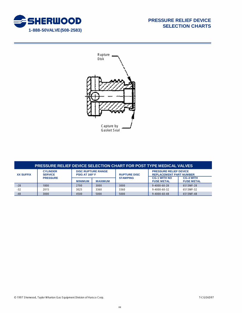
PRESSURE RELIEF DEVICE SELECTION CHART FOR POST TYPE MEDICAL VALVESCYLINDER DISC RUPTURE RANGE PRESSURE RELIEF DEVICE
XX SUFFIX SERVICE PSIG AT 160º F RUPTURE DISC REPLACEMENT PART NUMBERPRESSURE STAMPING CG-1 WITH NO CG-4 WITH
MINIMUM MAXIMUM FUSE METAL FUSE METAL
-28 1800 2700 3000 3000 9-4000-60-28 6513MF-28-32 2015 3025 3360 3360 9-4000-60-32 6513MF-32
-48 3000 4500 5000 5000 9-4000-60-48 6513MF-48
© 1997 Sherwood, Taylor Wharton Gas Equipment Division of Harsco Corp. T-CGO6D97

© 2000 Sherwood, Harsco Corporation, Gas and Fluid Control Group T-CGD2FF97
1-888-50VALVE (508-2583)
1
IMPORTANT! This specification is intended for use with “AV” Valve Assemblies.
MAKE SURE YOU ARE USING THE CORRECT SPECIFICATION!
REFERENCE DATA:
PressureProof: 833 PSIG MinimumTest: 500 PSIG
Temperature - Storage Minimum: -65 FMaximum: 155 F
Temperature - OperatingMinimum: -50 FMaximum: 120 F
Cycle Life:Minimum: 5000 cycles
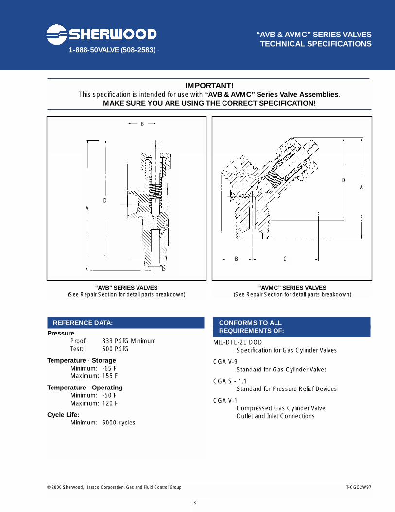
CONFORMS TO ALL REQUIREMENTS OF:
MIL-DTL-2E DOD Specification for Gas Cylinder Valves
CGA V-9 Standard for Gas Cylinder Valves
CGA V-1Compressed Gas Cylinder ValveOutlet and Inlet Connections
CGA S - 1.1Standard for Pressure Relief Devices
MATERIALS OF CONSTRUCTION FOR “AV” SERIES ACETYLENE VALVES
PART DESCRIPTION MATERIAL OF CONSTRUCTION
Body Forging Brass UNS Alloy #37700Packing Polypropylene MIL P-21922Packing Gland UNS Alloy #36000 Free Machining BrassPacking Nut UNS Alloy #36000 Free Machining BrassStem 1113, 1113X, or Lead Loy Steel, Cadmium Plated
TORQUE VALUES FOR “AV” SERIES ACETYLENE VALVES
DESCRIPTION TORQUE
Operating Torque @ 0 PSIG Inlet Pressure 4 - 6 in. lbs.Closing Torque @ 500 PSIG Inlet Pressure 14 - 16 in. lbs.Packing Nut Installation Torque 25 + 5 ft. lbs.Stem installation Torque 95 + 5 in. lbs.
“AV” SERIES ACETYLENE VALVES(See Repair Section for detail parts breakdown)
“AV” SERIES ACETYLENE VALVES TECHNICAL SPECIFICATIONS
BC
D A
© 2000 Sherwood, Harsco Corporation, Gas and Fluid Control Group T-CG02FF97
Sherwood and the “SS” symbol are trademarks of Sherwood, Harsco Corporation, Gas and Fluid Control GroupAll other names are trademarks of their respective owners.Printed in the USA
1-888-50VALVE (508-2583)
2
“AV” SERIES ACETYLENE VALVES TECHNICAL SPECIFICATIONS
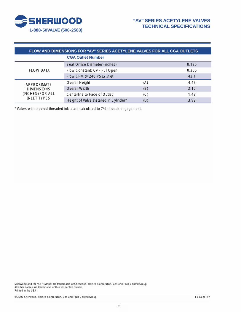
FLOW AND DIMENSIONS FOR “AV” SERIES ACETYLENE VALVES FOR ALL CGA OUTLETS
CGA Outlet Number
Seat Orifice Diameter (inches) 0.125
FLOW DATA Flow Constant: Cv - Full Open 0.365
Flow CFM @ 240 PSIG Inlet 43.1
Overall Height (A) 4.49
Overall Width (B) 2.10
Centerline to Face of Outlet (C) 1.48
Height of Valve Installed in Cylinder* (D) 3.99
* Valves with tapered threaded inlets are calculated to 73⁄4 threads engagement.
APPROXIMATEDIMENSIONS
(INCHES) FOR ALL INLET TYPES
© 2000 Sherwood, Harsco Corporation, Gas and Fluid Control Group T-CGO2W97
1-888-50VALVE (508-2583)
CONFORMS TO ALL REQUIREMENTS OF:
MIL-DTL-2E DOD Specification for Gas Cylinder Valves
CGA V-9 Standard for Gas Cylinder Valves
CGA S - 1.1Standard for Pressure Relief Devices
CGA V-1Compressed Gas Cylinder ValveOutlet and Inlet Connections
3
“AVB & AVMC” SERIES VALVESTECHNICAL SPECIFICATIONS
IMPORTANT! This specification is intended for use with “AVB & AVMC” Series Valve Assemblies.
MAKE SURE YOU ARE USING THE CORRECT SPECIFICATION!
REFERENCE DATA:
PressureProof: 833 PSIG MinimumTest: 500 PSIG
Temperature - StorageMinimum: -65 FMaximum: 155 F
Temperature - OperatingMinimum: -50 FMaximum: 120 F
Cycle Life:Minimum: 5000 cycles
“AVB” SERIES VALVES(See Repair Section for detail parts breakdown)
“AVMC” SERIES VALVES(See Repair Section for detail parts breakdown)
B
B C
DA
AD

© 2000 Sherwood, Harsco Corporation, Gas and Fluid Control Group T-CG02FF97
Sherwood and the “SS” symbol are trademarks of Sherwood, Harsco Corporation, Gas and Fluid Control GroupAll other names are trademarks of their respective owners.Printed in the USA
1-888-50VALVE (508-2583)
4
“AVB & AVMC” SERIES ACETYLENE VALVESTECHNICAL SPECIFICATIONS
MATERIALS OF CONSTRUCTION FOR “AVB & AVMC” SERIES VALVES
Part Description Material of Construction
Body Forging Brass UNS Alloy #37700, with 212° F Fusible Metal IntegralPressure Relief Device
Packing Teflon®
Packing Gland Free Machining Brass, UNS Alloy #36000 Packing Nut Free Machining Brass, UNS Alloy #36000 Packing Washer Free Machining Brass, UNS Alloy #36000 Retaining Ring (as required) Stainless Steel, ASTM A564Stem Steel Cold Rolled AISI-1144; Bright Zinc PlatedStrainer (as required) #60 Mesh Wire Monel Cloth
TORQUE VALUES FOR “AVB & AVMC” SERIES VALVES
Description Torque
Operating Torque @ 0 PSIG Inlet Pressure 6 to 10 in. lbs.Closing Torque @ 500 PSIG Inlet Pressure 6 to 10 in. lbs.Packing Nut Installation Torque 85 - 95 in. lbs.Stem Installation Torque 45 ± 5 in. lbs.
FLOW AND DIMENSIONS FOR “AVB & AVMC” SERIES VALVES
CGA Outlet Number 200 520
Seat Orifice Diameter (inches) 0.120 0.120
FLOW DATA Flow Constant: Cv - Full Open 0.140 0.150
Flow CFM @ 240 PSIG Inlet 16.5 17.7
Overall Height (A) 2.18 3.92
Centerline to Outside Face or Edge of Outlet (B) 0.56 0.84
Centerline to Edge of Stem (C) 1.41 N/A
Height of Valve Installed in Cylinder* (D) 1.79 3.53
* Valves with tapered threaded inlets are calculated to 73⁄4 threads engagement.
APPROXIMATEDIMENSIONS
(INCHES)
© 2000 Sherwood, Harsco Corporation, Gas and Fluid Control Group T-CGO2W97
1-888-50VALVE (508-2583)
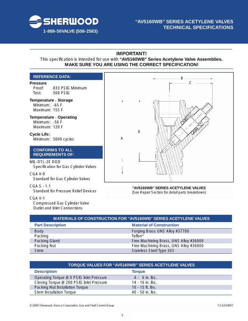
IMPORTANT! This specification is intended for use with “AV5160WB” Series Acetylene Valve Assemblies.
MAKE SURE YOU ARE USING THE CORRECT SPECIFICATION!
REFERENCE DATA:
PressureProof: 833 PSIG MinimumTest: 500 PSIG
Temperature - Storage Minimum: -65 FMaximum: 155 F
Temperature - OperatingMinimum: -50 FMaximum: 120 F
Cycle Life:Minimum: 5000 cycles
CONFORMS TO ALL REQUIREMENTS OF:
MIL-DTL-2E DOD Specification for Gas Cylinder Valves
CGA V-9 Standard for Gas Cylinder Valves
CGA S - 1.1Standard for Pressure Relief Devices
CGA V-1Compressed Gas Cylinder ValveOutlet and Inlet Connections
MATERIALS OF CONSTRUCTION FOR “AV5160WB” SERIES ACETYLENE VALVES
Part Description Material of Construction
Body Forging Brass UNS Alloy #37700Packing Teflon®
Packing Gland Free Machining Brass, UNS Alloy #36000Packing Nut Free Machining Brass, UNS Alloy #36000Stem Stainless Steel Type 303
TORQUE VALUES FOR “AV5160WB” SERIES ACETYLENE VALVES
Description Torque
Operating Torque @ 0 PSIG Inlet Pressure 14 - 16 in. lbs.Closing Torque @ 200 PSIG Inlet Pressure 14 - 16 in. lbs.Packing Nut Installation Torque 10 - 15 ft. lbs.Stem Installation Torque 40 - 50 in. lbs.
“AV5160WB” SERIES ACETYLENE VALVESTECHNICAL SPECIFICATIONS
“AV5160WB” SERIES ACETYLENE VALVES(See Repair Section for detail parts breakdown)
5
BC
A
D
“AV5160WB” SERIES ACETYLENE VALVESTECHNICAL SPECIFICATIONS
© 2000 Sherwood, Harsco Corporation, Gas and Fluid Control Group T-CG02FF97
Sherwood and the “SS” symbol are trademarks of Sherwood, Harsco Corporation, Gas and Fluid Control GroupAll other names are trademarks of their respective owners.Printed in the USA
1-888-50VALVE (508-2583)
Sherwood and the “SS” symbol are trademarks of Sherwood, Harsco Corporation, Gas and Fluid Control GroupAll other names are trademarks of their respective owners.Printed in the USA
6
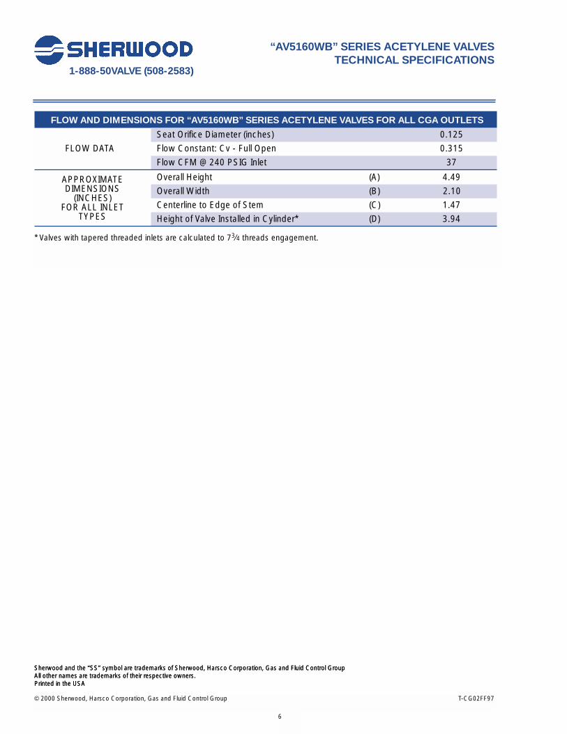
FLOW AND DIMENSIONS FOR “AV5160WB” SERIES ACETYLENE VALVES FOR ALL CGA OUTLETS
Seat Orifice Diameter (inches) 0.125
FLOW DATA Flow Constant: Cv - Full Open 0.315
Flow CFM @ 240 PSIG Inlet 37
Overall Height (A) 4.49
Overall Width (B) 2.10
Centerline to Edge of Stem (C) 1.47
Height of Valve Installed in Cylinder* (D) 3.94
* Valves with tapered threaded inlets are calculated to 73⁄4 threads engagement.
APPROXIMATEDIMENSIONS
(INCHES)FOR ALL INLET
TYPES
© 2000 Sherwood, Harsco Corporation, Gas and Fluid Control Group T-CG03W97
1-888-50VALVE (508-2583)
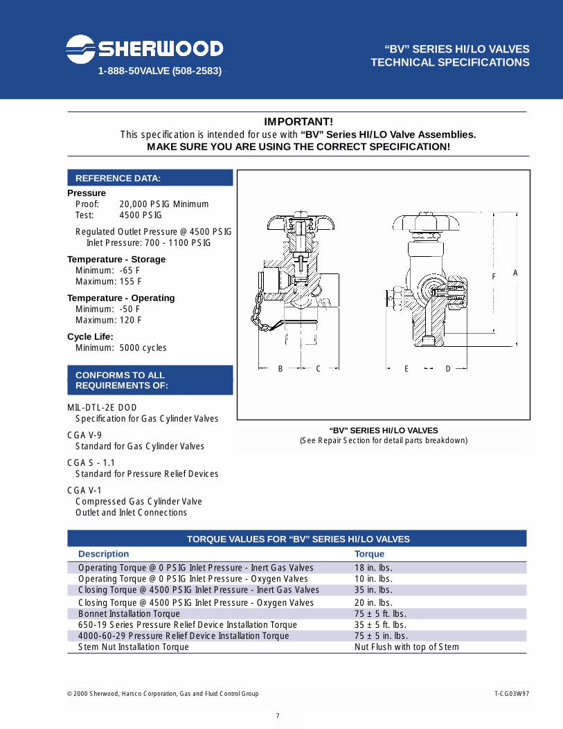
IMPORTANT! This specification is intended for use with “BV” Series HI/LO Valve Assemblies.
MAKE SURE YOU ARE USING THE CORRECT SPECIFICATION!
REFERENCE DATA:
Pressure Proof: 20,000 PSIG MinimumTest: 4500 PSIG
Regulated Outlet Pressure @ 4500 PSIGInlet Pressure: 700 - 1100 PSIG
Temperature - Storage Minimum: -65 FMaximum: 155 F
Temperature - Operating Minimum: -50 FMaximum: 120 F
Cycle Life:Minimum: 5000 cycles
CONFORMS TO ALL REQUIREMENTS OF:
MIL-DTL-2E DOD Specification for Gas Cylinder Valves
CGA V-9 Standard for Gas Cylinder Valves
CGA S - 1.1Standard for Pressure Relief Devices
CGA V-1Compressed Gas Cylinder ValveOutlet and Inlet Connections
TORQUE VALUES FOR “BV” SERIES HI/LO VALVES
Description Torque
Operating Torque @ 0 PSIG Inlet Pressure - Inert Gas Valves 18 in. lbs.Operating Torque @ 0 PSIG Inlet Pressure - Oxygen Valves 10 in. lbs.Closing Torque @ 4500 PSIG Inlet Pressure - Inert Gas Valves 35 in. lbs.Closing Torque @ 4500 PSIG Inlet Pressure - Oxygen Valves 20 in. lbs.Bonnet Installation Torque 75 ± 5 ft. lbs.650-19 Series Pressure Relief Device Installation Torque 35 ± 5 ft. lbs.4000-60-29 Pressure Relief Device Installation Torque 75 ± 5 in. lbs.Stem Nut Installation Torque Nut Flush with top of Stem
“BV” SERIES HI/LO VALVES TECHNICAL SPECIFICATIONS
“BV” SERIES HI/LO VALVES(See Repair Section for detail parts breakdown)
7
B C E D
F A
© 2000 Sherwood, Harsco Corporation, Gas and Fluid Control Group T-CG02FF97
Sherwood and the “SS” symbol are trademarks of Sherwood, Harsco Corporation, Gas and Fluid Control GroupAll other names are trademarks of their respective owners.Printed in the USA
1-888-50VALVE (508-2583)
8
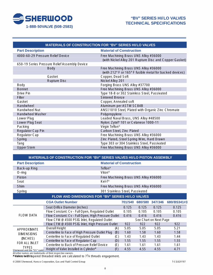
MATERIALS OF CONSTRUCTION FOR “BV” SERIES HI/LO VALVES
Part Description Material of Construction
4000-60-29 Pressure Relief Device Free Machining Brass UNS Alloy #36000 (with Nickel Alloy 201 Rupture Disc and Copper Gasket)
650-19 Series Pressure Relief Assembly Device Body Free Machining Brass UNS Alloy #36000
(with 212º F or 165º F fusible metal for backed devices)Gasket Copper, Dead SoftRupture Disc Nickel Alloy 201
Body Forging Brass UNS Alloy #37700Bonnet Free Machining Brass UNS Alloy #36000Drive Pin Type 18-8 or 302 Stainless Steel, PassivatedFilter Sintered BronzeGasket Copper, Annealed softHandwheel Aluminum per ASTM SC84BHandwheel Nut ANSI 1010 Steel, Plated with Organic Zinc ChromateHandwheel Washer PolypropyleneLower Plug Leaded Naval Brass, UNS Alloy #48500 Lower Plug Seat Nylon: Zytel® 101 or Celanese 1000-11Packing Virgin Teflon®
Regulator Cap Pin Carbon Steel, Zinc PlatedRegulator Cap Free Machining Brass UNS Alloy #36000 Spring Zinc Plated, Steel Spring Wire, Hard DrawnTang Type 303 or 304 Stainless Steel, PassivatedUpper Stem Free Machining Brass UNS Alloy #36000
MATERIALS OF CONSTRUCTION FOR “BV” SERIES VALVES HI/LO PISTON ASSEMBLY
Part Description Material of Construction
Back-up Ring Teflon®
O-ring Viton®
Piston Free Machining Brass UNS Alloy #36000Seat Kel-f ®
Shim Free Machining Brass UNS Alloy #36000Spring 301 Stainless Steel, Passivated
“BV” SERIES HI/LO VALVESTECHNICAL SPECIFICATIONS
FLOW AND DIMENSIONS FOR “BV” SERIES HI/LO VALVES
CGA Outlet Number 701/540 680/580 347/346 680/BS341#3
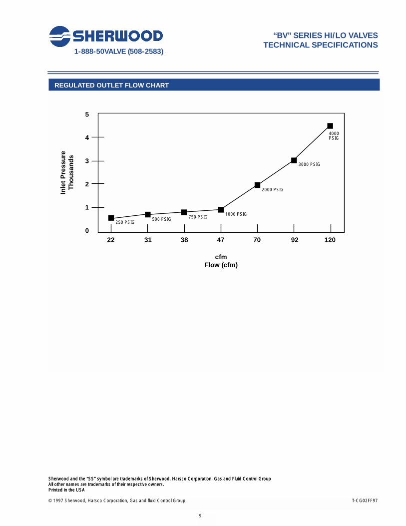
Seat Orifice Diameter (inches) 0.125 0.125 0.125 0.125Flow Constant: Cv - Full Open, Regulated Outlet 0.105 0.105 0.105 0.105Flow Constant: Cv - Full Open, High Pressure Outlet 0.416 0.416 0.416 0.416Flow CFM @ 4500 PSIG Inlet, Regulated Outlet See Chart on Next PageFlow CFM @ 4500 PSIG Inlet, High Pressure Outlet 922 922 922 922Overall Height (A) 5.05 5.05 5.05 5.21Centerline to Face of High Pressure Outlet Plug (B) 1.60 1.58 1.60 1.58Centerline to Face of Regulated Outlet (C) 1.43 1.43 1.43 1.44Centerline to Face of Regulator Cap (D) 1.55 1.55 1.55 1.55Centerline to Back of Pressure Relief Device (E) 1.61 1.61 1.61 1.61Height of Valve Installed in Cylinder* (F) 4.55 4.55 4.55 4.71
* Valves with tapered threaded inlets are calculated to 73⁄4 threads engagement.
APPROXIMATEDIMENSIONS
(INCHES)FOR ALL INLET
TYPES
FLOW DATA
© 1997 Sherwood, Harsco Corporation, Gas and fluid Control Group T-CG02FF97
Sherwood and the “SS” symbol are trademarks of Sherwood, Harsco Corporation, Gas and Fluid Control Group All other names are trademarks of their respective owners.Printed in the USA
1-888-50VALVE (508-2583)
Sherwood and the “SS” symbol are trademarks of Sherwood, Harsco Corporation, Gas and Fluid Control Group All other names are trademarks of their respective owners.Printed in the USA
9
“BV” SERIES HI/LO VALVESTECHNICAL SPECIFICATIONS
REGULATED OUTLET FLOW CHART
5
4
3
2
1
022 31 38 47 70 92 120
cfmFlow (cfm)
Inle
t P
ress
ure
Tho
usan
ds
250 PSIG500 PSIG 750 PSIG
1000 PSIG
2000 PSIG
3000 PSIG
4000PSIG

© 2000 Sherwood, Harsco Corporation, Gas and Fluid Control Group T-CG02FF97
Sherwood and the “SS” symbol are trademarks of Sherwood, Harsco Corporation, Gas and Fluid Control GroupAll other names are trademarks of their respective owners.Printed in the USA
Sherwood and the “SS” symbol are trademarks of Sherwood, Harsco Corporation, Gas and Fluid Control GroupAll other names are trademarks of their respective owners.Printed in the USA
10

© 2000 Sherwood, Harsco Corporation, Gas and Fluid Control Group T-CG03C97
1-888-50VALVE (508-2583)
DATA:
PressureProof: 3000 PSIG MinimumTest: 500 PSIG
Temperature - Storage Minimum: -60 FMaximum: 130 F
Temperature - OperatingMinimum: -50 FMaximum: 120 F
Cycle Life:Minimum: 1000 cycles when tested per CGA
pamphlet V-9
CONFORMS TO::MIL-DTL-2E DOD
Specification for Gas Cylinder Valves
CGA V-9 Standard for Compressed Gas Cylinder Valves
CGA S - 1.1Pressure Relief Device Standards-Part 1, cylinders forcompressed gas
CGA V-1Standard for Compressed Gas Cylinder Valve
Outlet and Inlet Connections
Chlorine Institute Pamphlet 17Plant Safety and Operational Guidelines
“1210-1214” SERIES CHLORINE VALVESTECHNICAL SPECIFICATIONS
1214 SERIES TON CONTAINER VALVES(Refer to Repair Manual for parts breakdown)
1210 SERIES CYLINDER VALVES(Refer to Repair Manual for parts breakdown)
11
IMPORTANT!This specification is intended for use with “1210-1214” Series Valve Assemblies.
MAKE SURE YOU ARE USING 1210 SERIES FOR CYLINDERS AND 1214 SERIES FOR TON CONTAINERS
CB
A
D C
B
A

© 2000 Sherwood, Harsco Corporation, Gas and Fluid Control Group T-CG02FF97
Sherwood and the “SS” symbol are trademarks of Sherwood, Harsco Corporation, Gas and Fluid Control GroupAll other names are trademarks of their respective owners.Printed in the USA
1-888-50VALVE (508-2583)
12
MATERIALS OF CONSTRUCTION FOR “1210-1214” SERIES VALVES
Part Description Material of Construction
Body Aluminum Silicon Bronze (CG4210)Fusible Plug PRD Naval Brass (C48500) with 165º F fusible metalOutlet Cap Brass (C36000)Packing Teflon® (1210x1 and 1214x1 series), Garlock 6130 (1210 and 1214 series)Packing Collar Naval Brass (C48500)Packing Gland Brass (C36000)Packing Nut Brass (C36000)Stem Monel (UNS No. 4400 or 4405)
TORQUE VALUES FOR “1210-1214” SERIES VALVES
Description Torque
Operating Torque @ 0 to 100 PSIG Inlet Pressure 30 - 35 in. lbs.Packing Nut Installation Torque 25-30 ft. lbs.Stem Installation Torque 40 - 50 in. lbs.
FLOW AND NOMINAL DIMENSIONS FOR “1210-1214” SERIES VALVES
Outlet Type Cylinder Ton Cylinder Valve Valve
Seat Orifice Diameter (inches) 0.187 0.312
Flow Constant: Cv - Full Open 0.733 1.88
Overall Height (A) 4.90 4.90
Overall Width (B) 2.10 2.01
Centerline to Face of Outlet Cap (C) 1.29 1.29
Centerline to Face of Pressure Relief Device (D) 0.81 N/A
“1210-1214” SERIES CHLORINE VALVESTECHNICAL SPECIFICATIONS
FLOW DATA
APPROXIMATE
DIMENSIONS
(INCHES) FOR ALL
INLET TYPES

© 2000 Sherwood, Harsco Corporation, Gas and Fluid Control Group T-CG02X97
1-888-50VALVE (508-2583)
“DF” SERIES VALVES TECHNICAL SPECIFICATIONS
“DF” SERIES HORIZONTAL STRAIGHTTHREADED VALVE ASSEMBLY
(See Repair Section for detail parts breakdown)
“DF” SERIES HORIZONTAL NGTTHREADED VALVE ASSEMBLY
(See Repair Section for detail parts breakdown)
“DF” SERIES UPRIGHTSTRAIGHT THREADED VALVE ASSEMBLY
(See Repair Section for detail parts breakdown)
“DF” SERIES UPRIGHTNGT THREADED VALVE ASSEMBLY
(See Repair Section for detail parts breakdown)
13
IMPORTANT!This specification is intended for use with “DF” Series Valve Assemblies.
MAKE SURE YOU ARE USING THE CORRECT SPECIFICATION!
A
D
CA
B
D
E
C
E
A
F
C
EA
F
B
E

© 2000 Sherwood, Harsco Corporation, Gas and Fluid Control Group T-CG02FF97
Sherwood and the “SS” symbol are trademarks of Sherwood, Harsco Corporation, Gas and Fluid Control GroupAll other names are trademarks of their respective owners.Printed in the USA
1-888-50VALVE (508-2583)
14
“DF” SERIES VALVESTECHNICAL SPECIFICATIONS
REFERENCE DATA:
PressureProof: 20,000 PSIGTest: Cylinder Service Pressure
or 3600 PSIG (whichever is less)
Temperature - Storage Minimum: -65 FMaximum:155 F
Temperature - OperatingMinimum: -50 FMaximum:120 F
Cycle Life: 5,000 Minimum
CONFORMS TO ALL REQUIREMENTS OF:
MIL-DTL-2E DOD Specification for Gas Cylinder Valves
CGA V-9 Standard for Gas Cylinder Valves
CGA S - 1.1Standard for Pressure Relief Devices
CGA V-1Compressed Gas Cylinder ValveOutlet and Inlet Connections
TORQUE VALUES FOR “DF” SERIES VALVES
Description Torque
Operating Torque @ 0 PSIG Inlet Pressure 10 in. lbs.Closing Torque @ 3600 PSIG Inlet Pressure 13 in. lbs.Bonnet Installation Torque 45 - 55 ft. lbs.Pressure Relief Device Installation Torque 35 ± 5 ft. lbs.Stem Nut Installation Torque Nut Flush with top of Stem
MATERIALS OF CONSTRUCTION FOR “DF” SERIES VALVES
Part Description Material of Construction
Body Forging Brass UNS Alloy #37700Bonnet Free Machining Brass UNS Alloy #36000Handwheel Aluminum per ASTM SC84BHandwheel Nut ANSI 1010 Steel, Plated with Organic Zinc ChromateLower Plug Teflon® Coated, Leaded Naval Brass, UNS Alloy #48500 Lower Plug Seat Kel-f ®
Packing Virgin Teflon®
Pin Type 18-8 or 302 Stainless Steel, PassivatedPressure Relief Device Assembly
Body Free Machining Brass UNS Alloy #36000 (212º F or 165º F for backed devices)
Disc Nickel Alloy 201Gasket Copper, Dead Soft
Spring Zinc Plated, Steel Spring Wire, Hard DrawnTang Type 303 or 304 Stainless Steel, PassivatedUpper Stem Free Machining Brass UNS Alloy #36000Washer Polypropylene
INLET O-RING FOR STRAIGHT THREADED FOR “DF” SERIES VALVES
Size Material Part Number
1.125 UNF Buna 70 Durometer G216A

© 1997 Sherwood, Harsco Corporation. T-CG02X97
Sherwood and the “SS” symbol are trademarks of Sherwood, Harsco Corporation, Gas and Fluid Control Group All other names are trademarks of their respective owners.Printed in the USA
1-888-50VALVE (508-2583)
FLOW AND DIMENSIONS FOR “DF” SERIES VALVES
Outlet Type Horizontal Upright
Straight NGT Straight NGT
Seat Orifice Diameter (inches) 0.186 0.186 0.186 0.186
Flow Constant: Cv - Full Open 0.823 0.823 0.670 0.670
Flow CFM @ 3600 PSIG Inlet 1458 1458 1187 1187
Overall Height (A) 3.06 2.81 4.61 4.44
Overall Length (B) 5.06 5.02 N/A N/A
Overall Width (C) 2.50 2.50 2.71 2.71
Centerline to Top of Handwheel Nut (D) 3.66 3.62 N/A N/A
Height of Valve Installed in Cylinder* (E) 2.12 2.25 3.67 3.89
Centerline to Face of Pressure Relief Device (F) N/A N/A 1.46 1.46
* Valves with tapered threaded inlets are calculated to 73⁄4 threads engagement. Valves with straight threaded inlets are measured from top of the cylinder to the top of the Valve.
FLOW DATA
APPROXIMATE
DIMENSIONS
(INCHES) FOR ALL
INLET TYPES
“DF” SERIES VALVESTECHNICAL SPECIFICATIONS
15

16
© 2000 Sherwood, Harsco Corporation, Gas and Fluid Control Group T-CG02FF97
Sherwood and the “SS” symbol are trademarks of Sherwood, Harsco Corporation, Gas and Fluid Control GroupAll other names are trademarks of their respective owners.Printed in the USA

© 2000 Sherwood, Harsco Corporation, Gas and Fluid Control Group T-CG02GG97
1-888-50VALVE (508-2583)
17
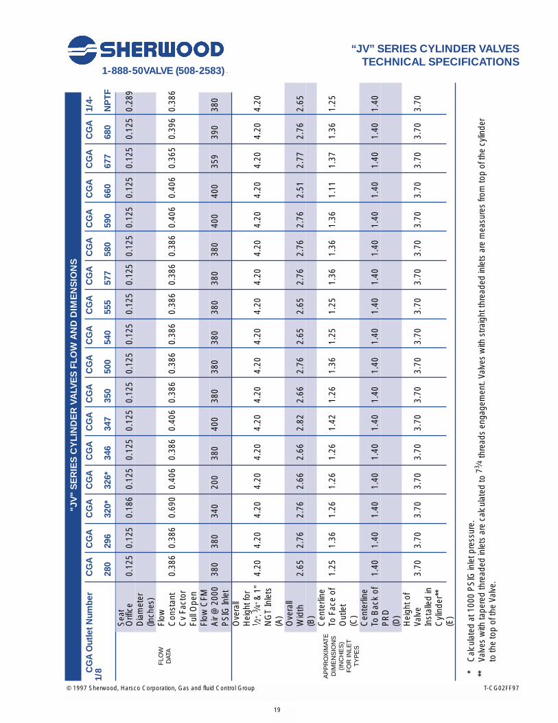
“JV” SERIES CYLINDER VALVESTECHNICAL SPECIFICATIONS
REFERENCE DATA:
Pressure Proof: 20,000 PSIG MinimumTest: Cylinder Service Pressure or
3000 PSIG (whichever is less)
Temperature - Storage Minimum: -65 FMaximum: 155 F
Temperature - Operating Minimum: -50 FMaximum: 120 F
Cycle Life:Minimum: 5000 cycles
CONFORMS TO ALL REQUIREMENTS OF:
CGA S - 1.1 Standard for PressureRelief Devices
CGA V-1 Compressed Gas CylinderValve Outlet and Inlet Connections
CGA V-9 Standard for Gas Cylinder Valves
TORQUE VALUES FOR “JV” SERIES CYLINDER VALVES
DESCRIPTION TORQUE
Operating Torque @ 0 PSIG Inlet Pressure 1 - 2 in. lbs.
Closing Torque @ 2000 PSIG Inlet Pressure 5 - 6 in. lbs.
Bonnet Installation Torque 45 - 55 ft. lbs.
Stem Nut installation Torque 35 + 5 in. lbs.
IMPORTANT!This specification is intended for use with “JV” SERIES CYLINDER VALVE ASSEMBLIES.
MAKE SURE YOU ARE USING THE CORRECT SPECIFICATION!
“JV” SERIES CYLINDER VALVES(See Repair Section for detail parts breakdown)
D C
EA
B

© 2000 Sherwood, Harsco Corporation, Gas and Fluid Control Group T-CG02FF97
Sherwood and the “SS” symbol are trademarks of Sherwood, Harsco Corporation, Gas and Fluid Control GroupAll other names are trademarks of their respective owners.Printed in the USA
1-888-50VALVE (508-2583)
18
“JV” SERIES CYLINDER VALVESTECHNICAL SPECIFICATIONS
MATERIALS OF CONSTRUCTION FOR “JV” SERIES CYLINDER VALVES
PART DESCRIPTION MATERIAL OF CONSTRUCTION
Backup Rings 15% Glass Filled Teflon®
Body Forging Brass UNS Alloy #37700Bonnet Free Machining Brass UNS Alloy #36000Handwheel Aluminum per ASTM SC84BLock Nut Carbon Steel with Nylon InsertLower Plug Leaded Naval Brass, UNS Alloy #48500Lower Plug Seat Nylon: Zytel® 101 or Celanese 1000-11O-rings Ethylene PropylenePin Carbon Steel Zinc PlatedPressure Relief Device Assembly
Body Free Machining Brass UNS Alloy #36000 (with 212° F or 165° F fusible metal for backed devices)
Rupture Disc Nickel Alloy 201Gasket Copper- Dead Soft
Stem Free Machining Brass UNS Alloy #36000Tang Type 303 or 304 Stainless Steel, PassivatedWasher Delrin®
"JV
" S
ER
IES
CY
LIN
DE
R V
ALV
ES
FLO
W A
ND
DIM
EN
SIO
NS
CG
A O
utle
t Num
ber
CG
AC
GA
CG
AC
GA
CG
AC
GA
CG
AC
GA
CG
AC
GA
CG
AC
GA
CG
AC
GA
CG
AC
GA
1/4-
1/8
280
296
320*
326*
346
347
350
500
540
555
577
580
590
660
677
680
NP
TF
Sea
tO
rific
e0.
125
0.12
50.
186
0.12
50.
125
0.12
50.
125
0.12
50.
125
0.12
50.
125
0.12
50.
125
0.12
50.
125
0.12
50.
289
Dia
met
er(In
ches
)Fl
owC
onst
ant
0.38
60.
386
0.69
00.
406
0.38
60.
406
0.38
60.
386
0.38
60.
386
0.38
60.
386
0.40
60.
406
0.36
50.
396
0.38
6C
v Fa
ctor
Full
Ope
nFl
ow C
FMA
ir @
200
038
038
034
020
038
040
038
038
038
038
038
038
040
040
035
939
038
0P
SIG
Inle
tO
vera
llH
eigh
t for
1 ⁄2",
3 ⁄4"&
1"4.
204.
204.
204.
204.
204.
204.
204.
204.
204.
204.
204.
204.
204.
204.
204.
204.
20N
GT
Inle
ts(A
)O
vera
llW
idth
2.65
2.76
2.76
2.66
2.66
2.82
2.66
2.76
2.65
2.65
2.76
2.76
2.76
2.51
2.77
2.76
2.65
(B)
Cen
terli
neTo
Fac
e of
1.25
1.36
1.26
1.26
1.26
1.42
1.26
1.36
1.25
1.25
1.36
1.36
1.36
1.11
1.37
1.36
1.25
Out
let
(C)
Cen
terli
neTo
Bac
k of
1.40
1.40
1.40
1.40
1.40
1.40
1.40
1.40
1.40
1.40
1.40
1.40
1.40
1.40
1.40
1.40
1.40
PR
D(D
)H
eigh
t of
Valv
e3.
703.
703.
703.
703.
703.
703.
703.
703.
703.
703.
703.
703.
703.
703.
703.
703.
70In
stal
led
inC
ylin
der*
*(E
)
* C
alcu
late
d at
100
0 P
SIG
inle
t pre
ssur
e.**
Va
lves
with
tape
red
thre
aded
inle
ts a
re c
alcu
late
d to
73 ⁄4
thre
ads
enga
gem
ent.
Valv
es w
ith s
traig
ht th
read
ed in
lets
are
mea
sure
s fro
m to
p of
the
cylin
der
to th
e to
p of
the
Valv
e.
© 1997 Sherwood, Harsco Corporation, Gas and fluid Control Group T-CG02FF97
1-888-50VALVE (508-2583)
19
“JV” SERIES CYLINDER VALVESTECHNICAL SPECIFICATIONS
FLO
W
DAT
A
AP
PR
OX
IMAT
ED
IME
NS
ION
S(I
NC
HE
S)
FO
R IN
LET
TY
PE
S

20
© 2000 Sherwood, Harsco Corporation, Gas and Fluid Control Group T-CG02FF97
Sherwood and the “SS” symbol are trademarks of Sherwood, Harsco Corporation, Gas and Fluid Control GroupAll other names are trademarks of their respective owners.Printed in the USA
© 2000 Sherwood, Harsco Corporation, Gas and Fluid Control Group T-CG02AA97
1-888-50VALVE (508-2583)
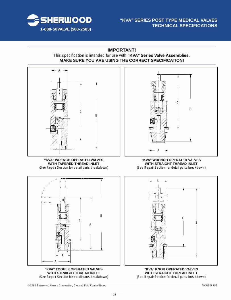
“KVA” SERIES POST TYPE MEDICAL VALVESTECHNICAL SPECIFICATIONS
“KVA” WRENCH OPERATED VALVESWITH TAPERED THREAD INLET
(See Repair Section for detail parts breakdown)
“KVA” WRENCH OPERATED VALVESWITH STRAIGHT THREAD INLET
(See Repair Section for detail parts breakdown)
“KVA” TOGGLE OPERATED VALVESWITH STRAIGHT THREAD INLET
(See Repair Section for detail parts breakdown)
“KVA” KNOB OPERATED VALVESWITH STRAIGHT THREAD INLET
(See Repair Section for detail parts breakdown)
21
IMPORTANT!This specification is intended for use with “KVA” Series Valve Assemblies.
MAKE SURE YOU ARE USING THE CORRECT SPECIFICATION!
A
CB
C
B
A
B
B
A
CB
A
A
C

© 2000 Sherwood, Harsco Corporation, Gas and Fluid Control Group T-CG02FF97
Sherwood and the “SS” symbol are trademarks of Sherwood, Harsco Corporation, Gas and Fluid Control GroupAll other names are trademarks of their respective owners.Printed in the USA
1-888-50VALVE (508-2583)
22
“KVA” SERIES POST TYPE MEDICALVALVES TECHNICAL SPECIFICATIONS
REFERENCE DATA:
PressureProof: 12,000 PSIG MinimumTest: Cylinder Service Pressure
or 3000 PSIG (whichever is less)
Temperature - Storage Minimum: -65 FMaximum: 155 F
Temperature - OperatingMinimum: -50 FMaximum: 120 F
Cycle Life: 5000 Cycles
CONFORMS TO ALL REQUIREMENTS OF:
MIL-DTL-2E DOD Specification for Gas Cylinder Valves
CGA V-9 Standard for Gas Cylinder Valves
CGA S - 1.1Standard for Pressure Relief Devices
CGA V-1Compressed Gas Cylinder ValvesOutlet and Inlet Connections
INLET O-RING FOR STRAIGHT THREADED “KVA” SERIES VALVES
Size Material Part Number
750-16 Viton® G210J750-16 Teflon® G210T
MATERIALS OF CONSTRUCTION FOR “KVA” SERIES VALVES
Part Description Material of Construction
Back-up Rings Teflon®
Body Chrome Plated Free Machining Brass UNS Alloy #36000Bonnet Chrome Plated Free Machining Brass UNS Alloy #36000Flange O-ring Viton®
Gasket CopperLower Plug Leaded Naval Brass, UNS Alloy #48500 Lower Plug Seat Nylon: Zytel® 201Packing Teflon®
Pressure Relief Device AssemblyBody Free Machining Brass UNS Alloy #36000
(212º F or 165º F for backed devices)Disc Nickel Alloy 201Retainer Gasket Nylon: Zytel 101
Flange Ring Free Machining Brass UNS Alloy #36000Spring Passivated Stainless Steel,Type 302Stem Chrome Plated Free Machining Brass UNS Alloy #36000Stem O-ring Viton®
Stem Washers Passivated Stainless Steel, Type 302Knob (if Applicable) Lexan®
Pin (if Applicable) 303 Stainless Steel; PassivatedToggle (if Applicable) Chrome Plated Free Machining Brass UNS Alloy #36000

© 1997 Sherwood, Harsco Corporation, Gas and fluid Control Group T-CG02FF97
Sherwood and the “SS” symbol are trademarks of Sherwood, Harsco Corporation, Gas and Fluid Control Group All other names are trademarks of their respective owners.Printed in the USA
1-888-50VALVE (508-2583)
23
TORQUE VALUES FOR “KVA” SERIES VALVES
Description Torque
WRENCH TAPERED Operating Torque @ 0 PSIG Inlet Pressure 3 in. lbs.Operating Torque @ 2000 PSIG Inlet Pressure 8 - 12 in. lbs.
WRENCH FLANGED Operating Torque @ 0 PSIG Inlet Pressure 1 - 2 in. lbs.Operating Torque @ 2000 PSIG Inlet Pressure 8 - 10 in. lbs.
TOGGLE Operating Torque @ 0 PSIG Inlet Pressure 1 - 2 in. lbs.Operating Torque @ 2000 PSIG Inlet Pressure 8 - 10 in. lbs.
KNOB FLANGED Operating Torque @ 0 PSIG Inlet Pressure 1 - 2 in. lbs.Operating Torque @ 2000 PSIG Inlet Pressure 8 - 10 in. lbs.
Bonnet Installation Torque 25 to 30 ft. lbs.Pressure Relief Device Installation Torque 50 to 65 in. lbs.
FLOW AND DIMENSIONS FOR “KVA” SERIES VALVES: CGA OUTLET NUMBERS 870 - 973
Seat Orifice Diameter (inches) 0.062
FLOW DATA Flow Constant: Cv - Full Open 0.102
Flow CFM @ 2000 PSIG Inlet Pressure 100
Wrench Operated, Tapered Thread Inlet (A) 0.875 x 1.00
APPROXIMATE DIMENSIONS Wrench Operated, Straight Thread Inlet (A) 1.24
(INCHES) Toggle Operated, Straight Thread Inlet (A) 1.24 - 2.36
Knob Operated, Straight Thread Inlet (A) 1.32
WRENCH For 1/2" NGT Inlets (B) 3.90
OPERATED For 3/4"-16 UNF Inlets (B) 4.20
TOGGLE For 1/2" NGT Inlets (B) N/A
OPERATED For 3/4"-16 UNF Inlets (B) 4.3 - 5.8
KNOB For 1/2" NGT Inlets (B) N/A
OPERATED For 3/4"-16 UNF Inlets (B) 4.90
WRENCH For 1/2" NGT Inlets (C) 3.40
OPERATED For 3/4"-16 UNF Inlets (C) 3.40
TOGGLE For 1/2" NGT Inlets (C) N/A
OPERATED For 3/4"-16 UNF Inlets (C) 3.6 - 5.1
KNOB For 1/2" NGT Inlets (C) N/A
OPERATED For 3/4"-16 UNF Inlets (C) 4.20
* Valves with tapered threaded inlets are calculated to 73⁄4 threads engagement. Valves with straight threaded inlets are measured from top of the cylinder to the top of the Valve.
“KVA” SERIES POST TYPE MEDICALVALVES TECHNICAL SPECIFICATIONS
APPROXIMATE OVERALL HEIGHT (INCHES)
APPROXIMATE HEIGHT OF
VALVE INSTALLED IN
CYLINDER*(INCHES)

© 2000 Sherwood, Harsco Corporation, Gas and Fluid Control Group T-CG02FF97
Sherwood and the “SS” symbol are trademarks of Sherwood, Harsco Corporation, Gas and Fluid Control GroupAll other names are trademarks of their respective owners.Printed in the USA
24
© 2000 Sherwood, Harsco Corporation, Gas and Fluid Control Group T-CG02CC97
1-888-50VALVE (508-2583)
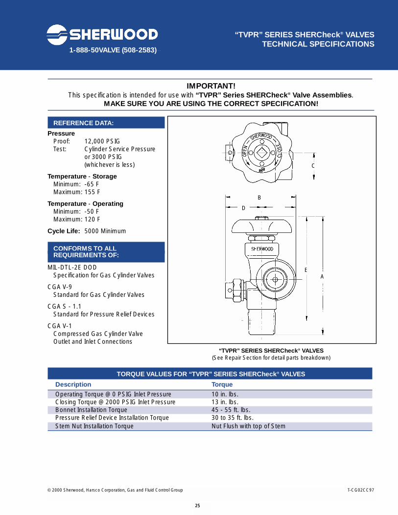
25
IMPORTANT! This specification is intended for use with “TVPR” Series SHERCheck® Valve Assemblies.
MAKE SURE YOU ARE USING THE CORRECT SPECIFICATION!
REFERENCE DATA:
PressureProof: 12,000 PSIGTest: Cylinder Service Pressure
or 3000 PSIG (whichever is less)
Temperature - Storage Minimum: -65 FMaximum: 155 F
Temperature - OperatingMinimum: -50 FMaximum: 120 F
Cycle Life: 5000 Minimum
CONFORMS TO ALL REQUIREMENTS OF:
MIL-DTL-2E DOD Specification for Gas Cylinder Valves
CGA V-9 Standard for Gas Cylinder Valves
CGA S - 1.1Standard for Pressure Relief Devices
CGA V-1Compressed Gas Cylinder Valve Outlet and Inlet Connections
TORQUE VALUES FOR “TVPR” SERIES SHERCheck® VALVES
Description Torque
Operating Torque @ 0 PSIG Inlet Pressure 10 in. lbs.Closing Torque @ 2000 PSIG Inlet Pressure 13 in. lbs.Bonnet Installation Torque 45 - 55 ft. lbs.Pressure Relief Device Installation Torque 30 to 35 ft. lbs.Stem Nut Installation Torque Nut Flush with top of Stem
“TVPR” SERIES SHERCheck® VALVESTECHNICAL SPECIFICATIONS
“TVPR” SERIES SHERCheck® VALVES(See Repair Section for detail parts breakdown)
25
C
AE
B
D

© 2000 Sherwood, Harsco Corporation, Gas and Fluid Control Group T-CG02FF97
Sherwood and the “SS” symbol are trademarks of Sherwood, Harsco Corporation, Gas and Fluid Control GroupAll other names are trademarks of their respective owners.Printed in the USA
1-888-50VALVE (508-2583)
26
MATERIALS OF CONSTRUCTION FOR “TVPR”SERIES SHERCheck® VALVES
Part Description Material of Construction
Body Forging Brass UNS Alloy #37700Bonnet Free Machining Brass UNS Alloy #36000Handwheel Aluminum per ASTM SC84BHandwheel Spring Zinc Plated Steel Spring Wire, Hard DrawnHandwheel Washer PolypropyleneLower Plug Leaded Naval Brass, UNS Alloy #48500 Lower Plug Seat Nylon: Zytel 101 or Celanese 1000-11Packing Virgin TeflonPin Type 18-8 or 302 Stainless Steel, PassivatedPressure Relief Device Assembly
Body Free Machining Brass UNS Alloy #36000 (with 212º F or 165º F fusible metal for backed devices)
Rupture Disc Nickel Alloy 201Gasket Copper, Dead Soft
Nut ANSI 1010 Steel, Plated with Organic Zinc ChromateTang Type 303 or 304 Stainless Steel, PassivatedUpper Stem Free Machining Brass UNS Alloy #36000
PISTON ASSEMBLY MATERIALS OF CONSTRUCTIONFOR “TVPR” SERIES SHERCheck® VALVES
Part Description Material of Construction
Cap Free Machining Brass UNS Alloy #36000Quad Ring Buna-NO-ring Buna-NPiston Type 303 Stainless Steel, PassivatedPiston Spring 302 Stainless SteelWasher Free Machining Brass UNS Alloy #36000
FLOW AND DIMENSIONS FOR “TVPR” SERIES SHERCheck® VALVES
CGA Outlet Number 350 580
Seat Orifice Diameter (inches) 0.125 0.125
Flow Constant: Cv - Full Open 0.363 0.363
Flow CFM @ 2000 PSIG Inlet 357 357
Overall Height (A) 4.70 4.70
Overall Width (B) 2.80 2.80
Centerline to Face of Outlet (C) 1.35 1.06
Centerline to Face of Pressure Relief Device (D) 1.45 1.45
Height of Valve Installed in Cylinder* (E) 4.15 4.15
* Valves with tapered threaded inlets are calculated to 73⁄4 threads engagement. Valves with straight threaded inlets are measured
“TVPR” SERIES SHERCheck® VALVESTECHNICAL SPECIFICATIONS
FLOW DATA
APPROXIMATEDIMENSIONS
(INCHES) FOR ALL INLET
TYPES

© 2000 Sherwood, Harsco Corporation, Gas and Fluid Control Group T-CG02BB97
1-888-50VALVE (508-2583)
27
IMPORTANT! This specification is intended for use with “TV” Series Manifold Valve Assemblies.
MAKE SURE YOU ARE USING THE CORRECT SPECIFICATION!
REFERENCE DATA:
PressureProof: 20,000 PSIGTest: 500 PSIG
Temperature - Storage Minimum: -65 FMaximum: 155 F
Temperature - OperatingMinimum: -50 FMaximum: 120 F
Cycle Life: 5000 Minimum
CONFORMS TO ALL REQUIREMENTS OF:
MIL-DTL-2E DOD Specification for Gas Cylinder Valves
CGA V-9 Standard for Gas Cylinder Valves
CGA S - 1.1Standard for Pressure Relief Devices
CGA V-1Compressed Gas Cylinder ValveOutlet and Inlet Connections
MATERIALS OF CONSTRUCTION FOR “TV” SERIES MANIFOLD VALVES
Part Description Material of Construction
Body Forging Brass UNS Alloy #37700/Nickel Chrome Plated when applicableBonnet Free Machining Brass UNS Alloy #36000/Nickel Chrome Plated when applicableHandwheel Aluminum per ASTM SC84B or Lexan®
Handwheel Nut AISI 1010 Steel, Plated with Organic Zinc ChromateLower Plug Teflon® Coated, Leaded Naval Brass, UNS Alloy #48500 Lower Plug Seat Nylon: Zytel® 101 or Celanese 1000-11O-ring NitritePacking Virgin Teflon®
Pin Type 18-8 or 302 Stainless Steel, PassivatedSpring Steel Wire, Cadmium PlatedTang Type 303 or 304 Stainless Steel, PassivatedUpper Stem Free Machining Brass UNS Alloy #36000Washer Polypropylene
“TV” SERIES MANIFOLD VALVESTECHNICAL SPECIFICATIONS
“TV” SERIES MANIFOLD VALVES(See Repair Section for detail parts breakdown)
27
B
DA
C
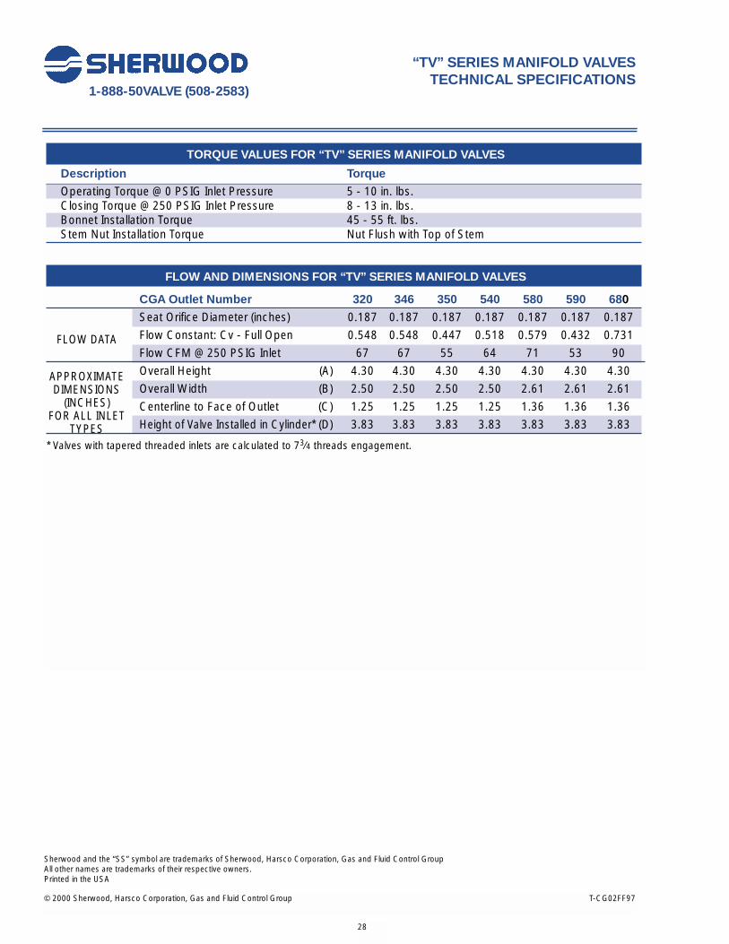
© 2000 Sherwood, Harsco Corporation, Gas and Fluid Control Group T-CG02FF97
Sherwood and the “SS” symbol are trademarks of Sherwood, Harsco Corporation, Gas and Fluid Control GroupAll other names are trademarks of their respective owners.Printed in the USA
1-888-50VALVE (508-2583)
28
TORQUE VALUES FOR “TV” SERIES MANIFOLD VALVES
Description Torque
Operating Torque @ 0 PSIG Inlet Pressure 5 - 10 in. lbs.Closing Torque @ 250 PSIG Inlet Pressure 8 - 13 in. lbs.Bonnet Installation Torque 45 - 55 ft. lbs.Stem Nut Installation Torque Nut Flush with Top of Stem
FLOW AND DIMENSIONS FOR “TV” SERIES MANIFOLD VALVES
CGA Outlet Number 320 346 350 540 580 590 680
Seat Orifice Diameter (inches) 0.187 0.187 0.187 0.187 0.187 0.187 0.187
Flow Constant: Cv - Full Open 0.548 0.548 0.447 0.518 0.579 0.432 0.731
Flow CFM @ 250 PSIG Inlet 67 67 55 64 71 53 90
Overall Height (A) 4.30 4.30 4.30 4.30 4.30 4.30 4.30
Overall Width (B) 2.50 2.50 2.50 2.50 2.61 2.61 2.61
Centerline to Face of Outlet (C) 1.25 1.25 1.25 1.25 1.36 1.36 1.36
Height of Valve Installed in Cylinder* (D) 3.83 3.83 3.83 3.83 3.83 3.83 3.83
* Valves with tapered threaded inlets are calculated to 73⁄4 threads engagement.
“TV” SERIES MANIFOLD VALVESTECHNICAL SPECIFICATIONS
FLOW DATA
APPROXIMATEDIMENSIONS
(INCHES) FOR ALL INLET
TYPES
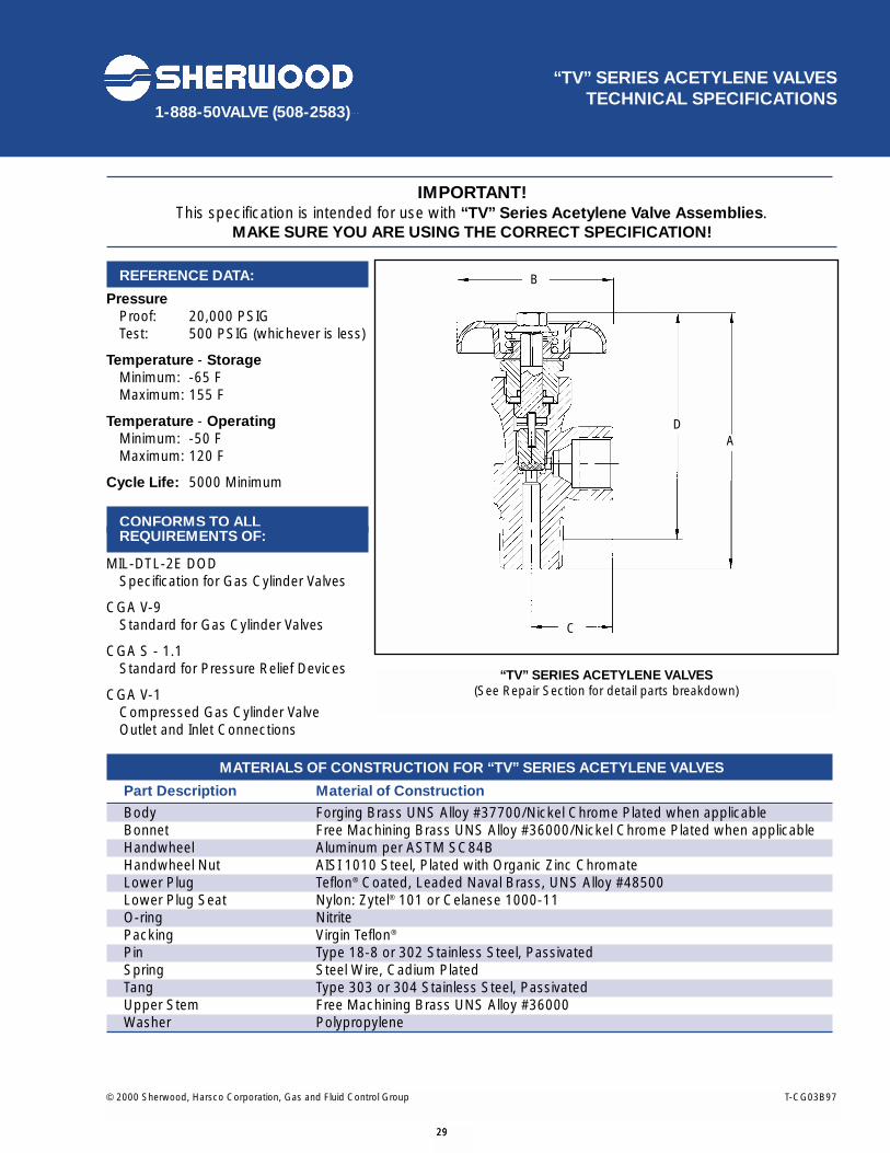
© 2000 Sherwood, Harsco Corporation, Gas and Fluid Control Group T-CG03B97
1-888-50VALVE (508-2583)
29
IMPORTANT! This specification is intended for use with “TV” Series Acetylene Valve Assemblies.
MAKE SURE YOU ARE USING THE CORRECT SPECIFICATION!
REFERENCE DATA:
PressureProof: 20,000 PSIGTest: 500 PSIG (whichever is less)
Temperature - Storage Minimum: -65 FMaximum: 155 F
Temperature - OperatingMinimum: -50 FMaximum: 120 F
Cycle Life: 5000 Minimum
CONFORMS TO ALL REQUIREMENTS OF:
MIL-DTL-2E DOD Specification for Gas Cylinder Valves
CGA V-9 Standard for Gas Cylinder Valves
CGA S - 1.1Standard for Pressure Relief Devices
CGA V-1Compressed Gas Cylinder ValveOutlet and Inlet Connections
MATERIALS OF CONSTRUCTION FOR “TV” SERIES ACETYLENE VALVES
Part Description Material of Construction
Body Forging Brass UNS Alloy #37700/Nickel Chrome Plated when applicableBonnet Free Machining Brass UNS Alloy #36000/Nickel Chrome Plated when applicableHandwheel Aluminum per ASTM SC84BHandwheel Nut AISI 1010 Steel, Plated with Organic Zinc ChromateLower Plug Teflon® Coated, Leaded Naval Brass, UNS Alloy #48500Lower Plug Seat Nylon: Zytel® 101 or Celanese 1000-11O-ring NitritePacking Virgin Teflon®
Pin Type 18-8 or 302 Stainless Steel, PassivatedSpring Steel Wire, Cadium PlatedTang Type 303 or 304 Stainless Steel, PassivatedUpper Stem Free Machining Brass UNS Alloy #36000Washer Polypropylene
“TV” SERIES ACETYLENE VALVESTECHNICAL SPECIFICATIONS
“TV” SERIES ACETYLENE VALVES(See Repair Section for detail parts breakdown)
29
B
DA
C

© 2000 Sherwood, Harsco Corporation, Gas and Fluid Control Group T-CG02FF97
Sherwood and the “SS” symbol are trademarks of Sherwood, Harsco Corporation, Gas and Fluid Control GroupAll other names are trademarks of their respective owners.Printed in the USA
1-888-50VALVE (508-2583)
30
TORQUE VALUES FOR “TV” SERIES ACETYLENE VALVES
Description Torque
Operating Torque @ 0 PSIG Inlet Pressure 5 - 10 in. lbs.Closing Torque @ 240 PSIG Inlet Pressure 8 - 13 in. lbs.Bonnet Installation Torque 45 - 55 ft. lbs.Stem Nut Installation Torque Nut Flush with top of Stem
FLOW AND DIMENSIONS FOR “TV” SERIES ACETYLENE VALVES
CGA Outlet Number 300 510
Seat Orifice Diameter (inches) 0.125 0.125
FLOW DATA Flow Constant: Cv - Full Open 0.565 0.565
Flow CFM @ 240 PSIG Inlet 66 66
Overall Height (A) 4.33 4.33
Overall Width (B) 2.50 2.61
Centerline to Face of Outlet (C) 1.25 1.36
Height of Valve Installed in Cylinder* (D) 3.83 3.83
* Valves with tapered threaded inlets are calculated to 7 3⁄4 threads engagement.
“TV” SERIES ACETYLENE VALVESTECHNICAL SPECIFICATIONS
APPROXIMATEDIMENSIONS
(INCHES) FOR ALL INLET
TYPES
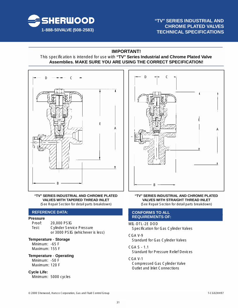
© 2000 Sherwood, Harsco Corporation, Gas and Fluid Control Group T-CG02HH97
1-888-50VALVE (508-2583)
31
“TV” SERIES INDUSTRIAL AND CHROME PLATED VALVES
TECHNICAL SPECIFICATIONS
IMPORTANT!This specification is intended for use with “TV” Series Industrial and Chrome Plated Valve
Assemblies. MAKE SURE YOU ARE USING THE CORRECT SPECIFICATION!
“TV” SERIES INDUSTRIAL AND CHROME PLATEDVALVES WITH TAPERED THREAD INLET
(See Repair Section for detail parts breakdown)
“TV” SERIES INDUSTRIAL AND CHROME PLATEDVALVES WITH STRAIGHT THREAD INLET
(See Repair Section for detail parts breakdown)
REFERENCE DATA:
PressureProof: 20,000 PSIGTest: Cylinder Service Pressure
or 3000 PSIG (whichever is less)
Temperature - Storage Minimum: -65 FMaximum: 155 F
Temperature - OperatingMinimum: -50 FMaximum: 120 F
Cycle Life:Minimum: 5000 cycles
CONFORMS TO ALL REQUIREMENTS OF:
MIL-DTL-2E DOD Specification for Gas Cylinder Valves
CGA V-9 Standard for Gas Cylinder Valves
CGA S - 1.1Standard for Pressure Relief Devices
CGA V-1Compressed Gas Cylinder ValveOutlet and Inlet Connections
D C
EA
B
D C
E
A
B

© 2000 Sherwood, Harsco Corporation, Gas and Fluid Control Group T-CG02FF97
Sherwood and the “SS” symbol are trademarks of Sherwood, Harsco Corporation, Gas and Fluid Control GroupAll other names are trademarks of their respective owners.Printed in the USA
1-888-50VALVE (508-2583)
32
“TV” SERIES INDUSTRIAL ANDCHROME PLATED VALVES
TECHNICAL SPECIFICATIONS
MATERIALS OF CONSTRUCTION FOR “TV” SERIES INDUSTRIAL AND CHROME PLATED VALVES
PART DESCRIPTION MATERIAL OF CONSTRUCTION
Body Forging Brass UNS Alloy #37700/Nickel Chrome Plated when applicableBonnet Free Machining Brass UNS Alloy #36000/Nickel Chrome Plated when applicableHandwheel Aluminum per ASTM SC84B or Lexan®
Handwheel Nut AISI 1010 Steel, Plated with Organic Zinc ChromateLower Plug Teflon® Coated, Leaded Naval Brass, UNS Alloy #48500 Lower Plug Seat Nylon: Zytel® 101 or Celanese 1000-11Packing Virgin TeflonPin Type 18-8 or 302 Stainless Steel, PassivatedPressure Relief Free Machining Brass UNS Alloy #36000
Device Body (with 212° F or 165° F fusible metal for backed devices)Pressure Relief Nickel Alloy 201 for all including fusible backed devices for natural gas service
Device Disc (Copper for all other fusible backed devices)Pressure Relief Copper, Dead Soft
Device GasketSpring Steel Wire, Cadmium PlatedTang Type 303 or 304 Stainless Steel, PassivatedUpper Stem Free Machining Brass UNS Alloy #36000Washer Polypropylene
TORQUE VALUES FOR “TV” SERIES INDUSTRIAL AND CHROME PLATED VALVES
DESCRIPTION TORQUE
Operating Torque @ 0 PSIG Inlet Pressure 5 - 10 in. lbs.Closing Torque @ 2000 PSIG Inlet Pressure 8 - 13 in. lbs.Bonnet Installation Torque 45 - 55 ft. lbs.Pressure Relief Device Installation Torque 35 + 5 ft. lbs.Stem Nut installation Torque Nut Flush with top of Stem
INLET O-RING FOR STRAIGHT THREADED “TV” SERIES INDUSTRIAL AND CHROME PLATED VALVES
SIZE MATERIAL PART NUMBER
0.625 UNF Buna G208ATeflon G208T
0.750 UNF Buna-N G210-9Teflon G210T
1.125 UNF Buna 70 Durometer G216A
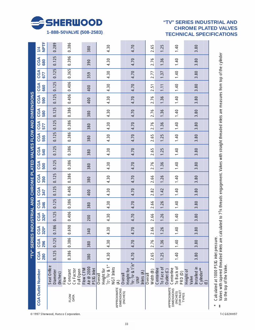
"TV
" S
ER
IES
IND
US
TR
IAL
AN
D C
HR
OM
E P
LAT
ED
VA
LVE
S F
LOW
AN
D D
IME
NS
ION
S
CG
A O
utle
t Num
ber
CG
AC
GA
CG
AC
GA
CG
AC
GA
CG
AC
GA
CG
AC
GA
CG
AC
GA
CG
AC
GA
CG
AC
GA
1/4
280
296
320*
326*
346
347
350
500
540
555
577
580
590
660
677
680
NP
TF
Sea
t Orif
ice
Dia
met
er0.
125
0.12
50.
186
0.12
50.
125
0.12
50.
125
0.12
50.
125
0.12
50.
125
0.12
50.
125
0.12
50.
125
0.12
50.
289
(Inch
es)
Flow
Con
stan
t0.
386
0.38
60.
690
0.40
60.
386
0.40
60.
386
0.38
60.
386
0.38
60.
386
0.38
60.
406
0.40
60.
365
0.39
60.
386
Cv
Fact
orFu
ll O
pen
Flow
CFM
Air
@ 2
000
380
380
340
200
380
400
380
380
380
380
380
380
400
400
359
390
380
PS
IG In
let
Ove
rall
Hei
ght f
or1 ⁄ 2
",3 ⁄ 4
"&
1"
4.30
4.30
4.30
4.30
4.30
4.30
4.30
4.30
4.30
4.30
4.30
4.30
4.30
4.30
4.30
4.30
4.30
NG
T In
lets
(A)
Ove
rall
Hei
ght f
or5 ⁄8
",3 ⁄4
"&
11 ⁄8"
4.70
4.70
4.70
4.70
4.70
4.70
4.70
4.70
4.70
4.70
4.70
4.70
4.70
4.70
4.70
4.70
4.70
UN
FIn
lets
(A)
Ove
rall
Wid
th (B
)2.
652.
762.
662.
662.
662.
822.
662.
762.
652.
652.
762.
762.
762.
512.
772.
762.
65C
ente
rline
To F
ace
of1.
251.
361.
261.
261.
261.
421.
261.
361.
251.
251.
361.
361.
361.
111.
371.
361.
25O
utle
t (C
)C
ente
rline
To B
ack
of1.
401.
401.
401.
401.
401.
401.
401.
401.
401.
401.
401.
401.
401.
401.
401.
401.
40P
RD
(D)
Hei
ght o
fVa
lve
Inst
alle
d in
3.80
3.80
3.80
3.80
3.80
3.80
3.80
3.80
3.80
3.80
3.80
3.80
3.80
3.80
3.80
3.80
3.80
Cyl
inde
r**
(E)
* C
alcu
late
d at
100
0 P
SIG
inle
t pre
ssur
e.**
Va
lves
with
tape
red
thre
aded
inle
ts a
re c
alcu
late
d to
73 ⁄4
thre
ads
enga
gem
ent.
Valv
es w
ith s
traig
ht th
read
ed in
lets
are
mea
sure
s fro
m to
p of
the
cylin
der
to th
e to
p of
the
Valv
e.
© 1997 Sherwood, Harsco Corporation. T-CG02HH97
1-888-50VALVE (508-2583)
33
“TV” SERIES INDUSTRIAL ANDCHROME PLATED VALVES
TECHNICAL SPECIFICATIONS
FLO
W
DAT
A
AP
PR
OX
IMAT
ED
IME
NS
ION
S(I
NC
HE
S)
FO
R IN
LET
TY
PE
S
AP
PR
OX
IMAT
ED
IME
NS
ION
S(I
NC
HE
S)

34
© 2000 Sherwood, Harsco Corporation, Gas and Fluid Control Group T-CG02FF97
Sherwood and the “SS” symbol are trademarks of Sherwood, Harsco Corporation, Gas and Fluid Control GroupAll other names are trademarks of their respective owners.Printed in the USA

© 2000 Sherwood, Harsco Corporation, Gas and Fluid Control Group T-CG02DDF97
1-888-50VALVE (508-2583)
35
IMPORTANT! This specification is intended for use with “YVA” Series Line Valve Assemblies.
MAKE SURE YOU ARE USING THE CORRECT SPECIFICATION!
REFERENCE DATA:
PressureProof: 25,000 PSIG Minimum
Test: System Service Pressure upto 6000 PSIG Maximum
Temperature - Storage Minimum: -65 FMaximum: 155 F
Temperature - OperatingMinimum: -50 FMaximum: 120 F
Cycle Life:Minimum: 5000 cycles
CONFORMS TO ALL REQUIREMENTS OF:
MIL-DTL-2E DOD Specification for Gas Cylinder Valves
CGA V-9 Standard for Gas Cylinder Valves
CGA S - 1.1Standard for Pressure Relief Devices
CGA V-1Compressed Gas Cylinder ValveOutlet and Inlet Connections
TORQUE VALUES FOR “YVA” SERIES LINE VALVES
Description Torque
Operating Torque @ 0 PSIG Inlet Pressure 1 - 2 in. lb.Closing Torque @ 2000 PSIG Inlet Pressure 2 - 3 in. lbs.Bonnet Installation Torque 25 to 30 ft. lbs.Stem Nut Installation Torque Nut Flush with top of Stem
“YVA” SERIES LINE VALVESTECHNICAL SPECIFICATIONS
“YVA” SERIES LINE VALVES(See Repair Section for detail parts breakdown)
35
C
B
A

© 2000 Sherwood, Harsco Corporation, Gas and Fluid Control Group T-CG02FF97
Sherwood and the “SS” symbol are trademarks of Sherwood, Harsco Corporation, Gas and Fluid Control GroupAll other names are trademarks of their respective owners.Printed in the USA
1-888-50VALVE (508-2583)
36
MATERIALS OF CONSTRUCTION FOR “YVA” SERIES LINE VALVES
Part Description Material of Construction
Body Forging Brass UNS Alloy #37700, Chrome PlatedBonnet Free Machining Brass, UNS ASTM B-16-53, Chrome PlatedGasket CopperHandwheel Lexan®
Handwheel Cap Lexan®
Lower Plug Leaded Naval Brass, UNS Alloy #C34200Lower Plug Seat Nylon: Zytel® 101 or Celanese 1000-11Packing (3506-18) Viton®
Packing (3506-7) Virgin Teflon®
Panel Mount Nut (as required) Free Machining Brass, UNS Alloy #36000, Chrome PlatedSpring Type 302 Stainless Steel, PassivatedStem Aluminum Silicon Bronze Alloy # 708-8, Nickel PlatedStem Nut Free Machining Brass, UNS Alloy 36000
FLOW AND DIMENSIONS FOR “YVA” SERIES LINE VALVES: FOR ALL OUTLET TYPES
Seat Orifice Diameter (inches) 0.120
Flow Constant: Cv - Full Open 0.284
Flow CFM @ 2000 PSIG Inlet 280
Overall Length (A) 2.50
Length of Valve Installed in Line* (B) 2.11
Centerline of Inlet to Top of Handwheel (C) 2.70
* Valves with tapered threaded inlets are calculated to 7 3⁄4 threads engagement.
“YVA” SERIES LINE VALVESTECHNICAL SPECIFICATIONS
FLOW DATA
APPROXIMATE DIMENSIONS(INCHES)
FOR ALL INLET TYPES

© 2000 Sherwood, Harsco Corporation, Gas and Fluid Control Group T-CG02EE97
1-888-50VALVE (508-2583)
37
IMPORTANT! This specification is intended for use with “YVB” Series Valve Assemblies.
MAKE SURE YOU ARE USING THE CORRECT SPECIFICATION!
REFERENCE DATA:
PressureProof: 12,000 PSIG Minimum
Test: Cylinder Service Pressureor 3000 PSIG(whichever is less)
Temperature - Storage Minimum: -65 FMaximum: 155 F
Temperature - OperatingMinimum: -50 FMaximum: 120 F
Cycle Life:Minimum: 5000 cycles
CONFORMS TO ALL REQUIREMENTS OF:
MIL-DTL-2E DOD Specification for Gas Cylinder Valves
CGA V-9 Standard for Gas Cylinder Valves
CGA S - 1.1Standard for Pressure Relief Devices
CGA V-1Compressed Gas Cylinder ValveOutlet and Inlet Connections
TORQUE VALUES FOR “YVB” SERIES VALVES
Description Torque
Operating Torque @ 0 PSIG Inlet Pressure 1 in. lb.Closing Torque @ 2000 PSIG Inlet Pressure 1 - 2 in. lbs.Bonnet Installation Torque 25 to 30 ft. lbs.Pressure Relief Device Installation Torque 50 to 65 in. lbs.Stem Nut Installation Torque Nut Flush with top of Stem
“YVB” SERIES VALVESTECHNICAL SPECIFICATIONS
“YVB” SERIES VALVES(See Repair Section for detail parts breakdown)
37
B
C
D
A

© 2000 Sherwood, Harsco Corporation, Gas and Fluid Control Group T-CG02FF97
Sherwood and the “SS” symbol are trademarks of Sherwood, Harsco Corporation, Gas and Fluid Control GroupAll other names are trademarks of their respective owners.Printed in the USA
1-888-50VALVE (508-2583)
“YVB” SERIES VALVESTECHNICAL SPECIFICATIONS
38
MATERIALS OF CONSTRUCTION FOR “YVB” SERIES VALVES
Part Description Material of Construction
Body Forging Brass UNS Alloy #37700, Chrome PlatedBonnet Free Machining Brass UNS ASTM B-16-53, Chrome PlatedFilter (as required) Sintered Bronze - 40 micronFilter Retainer (as required) Free Machining Brass UNS Alloy #36000Gasket CopperHandwheel Lexan®
Lower Plug Leaded Naval Brass, UNS Alloy #C34200Lower Plug Seat Nylon: Zytel® 101 or Celanese 1000-11O-ring Viton®
Packing Virgin Teflon®
Pressure Relief Device AssemblyBody Free Machining Brass UNS Alloy #36000
(with 212º F or 165º F fusible metal for backed devices)Rupture Disc Nickel Alloy 201Retainer Gasket Nylon: Zytel® 101 or Celanese 1000-11
Spring Type 302 Stainless Steel, PassivatedStem Aluminum Silicon Bronze Alloy # 708-8, Nickel PlatedStem Nut Free Machining Brass, UNS Alloy 36000
INLET O-RING FOR STRAIGHT THREADED “YVB” SERIES VALVES
Size Material Part Number
0.625 UNF Buna G208A
Teflon® G208T
0.750 UNF Buna-N G210A9
Teflon® G210T
FLOW AND DIMENSIONS FOR “YVB” SERIES VALVES: CGA OUTLET NUMBER 540
Seat Orifice Diameter (inches) 0.120
Flow Constant: Cv - Full Open 0.102
Flow CFM @ 2000 PSIG Inlet 100.4
Overall Height (A) 2.71
Overall Width (B) 2.83
Centerline to Face of Handwheel Nut (C) 2.15
Height of Valve Installed in Cylinder* (D) 1.90
* Valves with tapered threaded inlets are calculated to 7 3⁄4 threads engagement. Valves with straight threaded inlets are measured from top of the cylinder to the top of the Valve.
FLOW DATA
APPROXIMATE DIMENSIONS(INCHES)
FOR ALL INLET TYPES