technical specifications and operating protocols …€¦ · · 2007-11-13technical...
TRANSCRIPT
TECHNICAL SPECIFICATIONS
AND
OPERATING PROTOCOLS AND PROCEDURES
FOR
SMALL GENERATION INTERCONNECTIONS
Puget Sound Energy, Inc.
PSE-ET-160.60
October 30, 2007

PSE-ET-160.60
i
TABLE OF CONTENTS
1. INTRODUCTION.....................................................................................................................1 1.1 GENERAL POLICY ...................................................................................................1
1.2 COMPLIANCE WITH NERC INTERCONNECTION STANDARDS.....................1
2. PSE SYSTEM INFORMATION.............................................................................................5 2.1 VOLTAGE...................................................................................................................5
2.2 FREQUENCY..............................................................................................................5
2.3 PSE EFFECTIVE GROUNDING ...............................................................................5
3. SYSTEM INTEGRITY ............................................................................................................7 3.1 HARMONICS .............................................................................................................7
3.2 VOLTAGE - DISTRIBUTION LEVEL......................................................................9
3.3 VOLTAGE - TRANSMISSION LEVEL ..................................................................10
3.3.1 Voltage Control..................................................................................................11
3.3.2 Wind Power Induction Generating Facilities.....................................................12
4. GENERAL DESIGN REQUIREMENTS.............................................................................13 4.1 DISCONNECTING DEVICES .................................................................................13
4.2 INTERRUPTING DEVICES.....................................................................................13
4.3 STEP AND TOUCH POTENTIAL...........................................................................13
4.4 INSULATION COORDINATION............................................................................13
4.5 CONTROL REQUIREMENTS.................................................................................13
4.6 EFFECTIVE GROUNDING .....................................................................................14
4.7 EXCITATION EQUIPMENT, INCLUDING POWER SYSTEM STABILIZERS - TRANSMISSION CONNECTED GENERATING FACILITIES ........................................14
4.8 GOVERNOR REQUIREMENTS - TRANSMISSION CONNECTED GENERATING FACILITIES ................................................................................................15
4.9 INDUCTION GENERATORS..................................................................................15
4.10 INVERTER SYSTEMS.............................................................................................16
4.11 WIND POWER GENERATING FACILITIES.........................................................16
4.11.1 Production Control.........................................................................................16
5. MINIMUM INTERCONNECTION PROTECTION REQUIREMENTS .......................17 5.1 TYPICAL INTERCONNECTION REQUIREMENTS............................................17
5.2 MINIMUM SYSTEM REQUIREMENTS................................................................18

PSE-ET-160.60
ii
5.3 PROTECTION SYSTEM MODIFICATIONS .........................................................18
5.3.1 Modifications for Distribution Interconnections ...............................................18
5.3.2 Modifications for Substation Interconnections..................................................19
5.3.3 Modifications for Transmission Interconnections .............................................19
6. METERING: PSE REVENUE, OPERATIONS AND SCHEDULING REQUIREMENTS.......................................................................................................................21
6.1 GENERAL.................................................................................................................21
6.2 REVENUE METERING ...........................................................................................21
6.3 RTU (REMOTE TERMINAL UNIT) AND TELEMETRY METERING ...............23
6.3.1 Generator Sites With A Combined Output Less Than 2 MW ...........................23
6.3.2 Generator Sites With A Combined Output of 2 MW or Greater .......................23
6.4 GENERATION SCHEDULING REQUIREMENTS ...............................................24
6.5 EXPORTING ENERGY............................................................................................24
6.6 SCADA, RTU AND TELEMETRY REQUIREMENTS..........................................24
7. PROTECTION SETTINGS...................................................................................................27 7.1 INTERCONNECTION PROTECTION....................................................................27
7.2 GENERATION PROTECTION................................................................................28
7.2.1 Underfrequency / Overfrequency (81 O/U).......................................................28
7.2.2 Alternative to Meeting Underfrequency WECC Requirements ........................29
8. DEMONSTRATION OF INTERCONNECTION CUSTOMER’S PROTECTIVE DEVICES......................................................................................................................................31
8.1 GENERAL.................................................................................................................31
8.2 CALIBRATION ........................................................................................................31
8.2.1 Current Transformer (CT)..................................................................................31
8.2.2 Voltage Transformer (VT), Potential Device (PD), Capacitor Voltage Transformer (CVT), and Coupling-Capacitor Voltage Transformer (CCVT)...............32
8.2.3 Relays.................................................................................................................32
8.2.4 Testing and Calibration......................................................................................32
8.3 TRIP AND CIRCUIT CHECKS ...............................................................................32
9. DEMONSTRATION OF GENERATING SYSTEM FUNCTIONALITY.......................35 9.1 ON-LINE START-UP TESTING..............................................................................35
9.1.1 Synchronous Generators ....................................................................................36
9.1.2 Induction Generators..........................................................................................36
9.2 POWER FACTOR (PF) CONTROLLER TEST.......................................................36
PSE-ET-160.60
iii
9.3 VAR CAPACITY TESTS .........................................................................................37
9.3.1 Distribution Connected Generators....................................................................37
9.3.2 Transmission Connected Generators .................................................................37
9.3.3 Transmission Connected Wind Power Generating Facilities ............................38
9.4 AUTOMATIC GENERATION CONTROL DISPATCHABILITY TESTING.......38
9.5 POWER SYSTEM STABILIZER TESTS AND TUNING ......................................38
9.6 WECC-REQUIRED INITIAL AND PERIODIC TESTING....................................38
10. GENERAL MAINTENANCE REQUIREMENTS ...........................................................41 10.1 INSPECTION ............................................................................................................41
10.2 ANNUAL DEMONSTRATION ...............................................................................41
10.3 CALIBRATION DEMONSTRATION (EVERY 3 YEARS)...................................42
10.4 DESIGN CHANGES AFTER COMMERCIAL OPERATION ...............................42
11. OPERATING REQUIREMENTS ......................................................................................43 11.1 SWITCHING AND TAGGING RULES...................................................................43
11.2 DE-ENERGIZED CIRCUITS ...................................................................................43
11.3 OPERATING LOG....................................................................................................43
11.4 COMMUNICATIONS – FACILITIES 2 MW AND GREATER.............................43
11.5 DISCONTINUANCE OF OPERATIONS ................................................................44
ATTACHMENTS 1 through 6 ...................................................................................................45
INTERCONNECTION PROTECTION AND METERING DIAGRAMS ...........................45
DISTRIBUTION SECONDARY CONNECTIONS > 25 KW TO ≤ 300 KW......................46
DISTRIBUTION SECONDARY CONNECTIONS > 300 KW TO ≤ 5 MW.......................47
DISTRIBUTION SECONDARY CONNECTIONS > 5 MW TO ≤ 10 MW ........................48
TRANSMISSION CONNECTIONS......................................................................................49
METERING – OPTION “A”..................................................................................................50
METERING – OPTION “B”..................................................................................................51
APPENDIX A............................................................................................................................ A-1
TECHNICAL SPECIFICATIONS AND OPERATING PROTOCOLS AND PROCEDURES FOR SMALL GENERATION INTERCONNECTIONS ........................ A-1
APPENDIX B .............................................................................................................................B-1 TECHNICAL SPECIFICATIONS AND OPERATING PROTOCOLS AND PROCEDURES FOR SMALL GENERATION INTERCONNECTIONS .........................B-1
PSE-ET-160.60
1
1. INTRODUCTION
1.1 GENERAL POLICY This document is issued in connection with the Federal Energy Regulatory Commission’s (FERC) order, Standardization of Generator Interconnection Agreements and Procedures, Final Rule, Order No. 2003, Fed. Reg. 49,846 (Aug. 19, 2003), 104 FERC ¶ 61,103 (issued July 24, 2003) (the “Order”) and the Standard Small Generator Interconnection Agreement (SGIA) set forth in the Order. All capitalized terms used in this document are used with same meanings given to them in the Order and the SGIA. The requirements stated in this document are intended to ensure, pursuant to Section 5.10.2 of the SGIA, that the Interconnection Customer's Interconnection Facilities (ICIF) are compatible with the telemetry, communications and safety requirements of PSE. In addition, the requirements stated in this document are intended to provide, pursuant to Section 9.3 of the SGIA, operating instructions to the Interconnection Customer consistent with the SGIA and these operating protocols and procedures. To those ends, the requirements cover the necessary interconnection equipment (relays, breakers, etc.) to be installed, owned, and maintained by the Interconnection Customer and the ICIF needed to disconnect parallel generation from PSE’s electric system whenever a fault or abnormality occurs. Any modifications to this document will be provided to applicable Interconnection Customers. For purposes of this document and the SGIA, “Applicable Reliability Council” means the Western Electricity Coordinating Council (WECC). Interconnection Customers and PSE personnel shall apply this document and the system reliability performance requirements of the North American Electric Reliability Corporation (NERC), WECC, Northwest Power Pool (NWPP) and PSE when planning installations of independently owned or controlled generation throughout the planning horizon.
1.2 COMPLIANCE WITH NERC INTERCONNECTION STANDARDS
NERC Standard FAC-001-0 Facility Connection Requirements, in requirement R2.1, states the Transmission Owner shall, “Provide a written summary of its plans to achieve the required system performance...throughout the planning horizon.” This document represents such a written summary of PSE’s plans to achieve the required system performance of requirement 2.1. Additionally, Requirement R2.1.1 states the written summary will address, “Procedures for coordinated joint studies of new facilities and their impacts on the interconnected transmission systems.” To meet this requirement, studies performed by the Interconnection Customer and PSE to achieve the required system performance may include, but are not limited to, short circuit, power flow, transient stability, and

PSE-ET-160.60
2
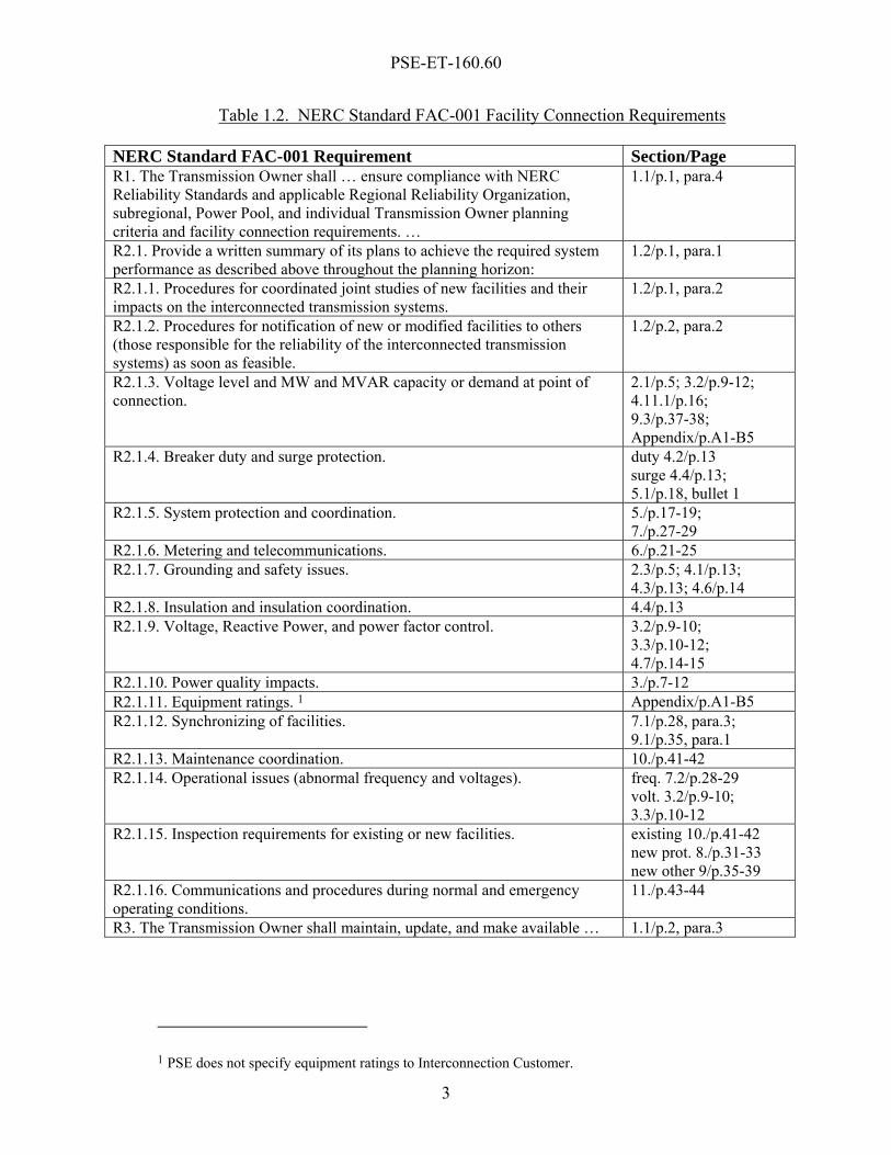
harmonics. With respect to coordination, the planning of Interconnection installations will be coordinated through phone calls and conference calls, meetings, possible site visits, and sharing study results and data with affected transmission owners. WECC policies, procedure and guidelines governing the coordination of plans include “WECC Progress Report Policies and Procedures”, and “WECC Policies and Procedures for Regional Planning Project Review, Project Rating Review, and Progress Reports”. Requirement 2.1.2 further states that the written summary will address, ”Procedures for notification of new or modified facilities to others (those responsible for the reliability of the interconnected transmission systems) as soon as feasible.” To comply with this requirement, plans for new or modified facilities will be provided to PSE’s interconnection customer as governed by PSE’s tariff. Additionally, plans for new or modified facilities will be provided to WECC when they can be made publicly available, which involves announcing such plans on OASIS. Documents governing the notification of plans, and providing models for modification of new or modified facilities include “WECC Progress Report Policies and Procedures”, “WECC Policies and Procedures for Regional Planning Project Review, Project Rating Review, and Progress Reports”, “WECC Data Preparation Procedural Manual for Power Flow and Stability Studies”, “WECC Dynamic Modeling Procedure”, and “WECC Approved Dynamic Model Library”. Requirement R3 states that PSE shall maintain and update these facility connection requirements as required. These facility connection requirements shall be maintained and updated from time to time as required. Requirement R3 further states that PSE shall make documentation of these requirements available to the users of the transmission system, WECC, and NERC on request (five business days). Documents of these requirements shall be made available to the users of the transmission system, WECC, and NERC on request (five business days). This document provides for compliance for PSE with NERC Standard FAC-001. This section provides direction to find compliance with the requirements in FAC-001. The following Table 1.2 gives the location in this document where each requirement of FAC-001 R1 and R2 is met. Some requirements are general and are addressed in many locations, but at least some of the locations are listed.
PSE-ET-160.60
3
Table 1.2. NERC Standard FAC-001 Facility Connection Requirements
NERC Standard FAC-001 Requirement Section/Page R1. The Transmission Owner shall … ensure compliance with NERC Reliability Standards and applicable Regional Reliability Organization, subregional, Power Pool, and individual Transmission Owner planning criteria and facility connection requirements. …
1.1/p.1, para.4
R2.1. Provide a written summary of its plans to achieve the required system performance as described above throughout the planning horizon:
1.2/p.1, para.1
R2.1.1. Procedures for coordinated joint studies of new facilities and their impacts on the interconnected transmission systems.
1.2/p.1, para.2
R2.1.2. Procedures for notification of new or modified facilities to others (those responsible for the reliability of the interconnected transmission systems) as soon as feasible.
1.2/p.2, para.2
R2.1.3. Voltage level and MW and MVAR capacity or demand at point of connection.
2.1/p.5; 3.2/p.9-12; 4.11.1/p.16; 9.3/p.37-38; Appendix/p.A1-B5
R2.1.4. Breaker duty and surge protection. duty 4.2/p.13 surge 4.4/p.13; 5.1/p.18, bullet 1
R2.1.5. System protection and coordination. 5./p.17-19; 7./p.27-29
R2.1.6. Metering and telecommunications. 6./p.21-25 R2.1.7. Grounding and safety issues. 2.3/p.5; 4.1/p.13;
4.3/p.13; 4.6/p.14 R2.1.8. Insulation and insulation coordination. 4.4/p.13 R2.1.9. Voltage, Reactive Power, and power factor control. 3.2/p.9-10;
3.3/p.10-12; 4.7/p.14-15
R2.1.10. Power quality impacts. 3./p.7-12 R2.1.11. Equipment ratings. 1 Appendix/p.A1-B5 R2.1.12. Synchronizing of facilities. 7.1/p.28, para.3;
9.1/p.35, para.1 R2.1.13. Maintenance coordination. 10./p.41-42 R2.1.14. Operational issues (abnormal frequency and voltages). freq. 7.2/p.28-29
volt. 3.2/p.9-10; 3.3/p.10-12
R2.1.15. Inspection requirements for existing or new facilities. existing 10./p.41-42 new prot. 8./p.31-33 new other 9/p.35-39
R2.1.16. Communications and procedures during normal and emergency operating conditions.
11./p.43-44
R3. The Transmission Owner shall maintain, update, and make available … 1.1/p.2, para.3
1 PSE does not specify equipment ratings to Interconnection Customer.


PSE-ET-160.60
5
2. PSE SYSTEM INFORMATION
2.1 VOLTAGE PSE’s most common primary local distribution voltage is 12.47 kV. Other local distribution voltages are sometimes used in specific areas (example 4.16 kV or 34.5 kV). The majority of the distribution circuits are “effectively grounded” (see Section 2.3) and are used for four-wire distribution (phase to neutral) connected loads. Other voltages of PSE’s electrical system are 57.5 kV, 115 kV and 230 kV. 115 kV and 230 kV are the most typical transmission facility voltages.
2.2 FREQUENCY The frequency for connection to the PSE’s system must be 60 Hz sinusoidal alternating current at a standard voltage (see Section 2.1) and phase rotation.
2.3 PSE EFFECTIVE GROUNDING PSE maintains effective grounding on its distribution and transmission systems as defined by IEEE Std. 142.

PSE-ET-160.60
7
3. SYSTEM INTEGRITY
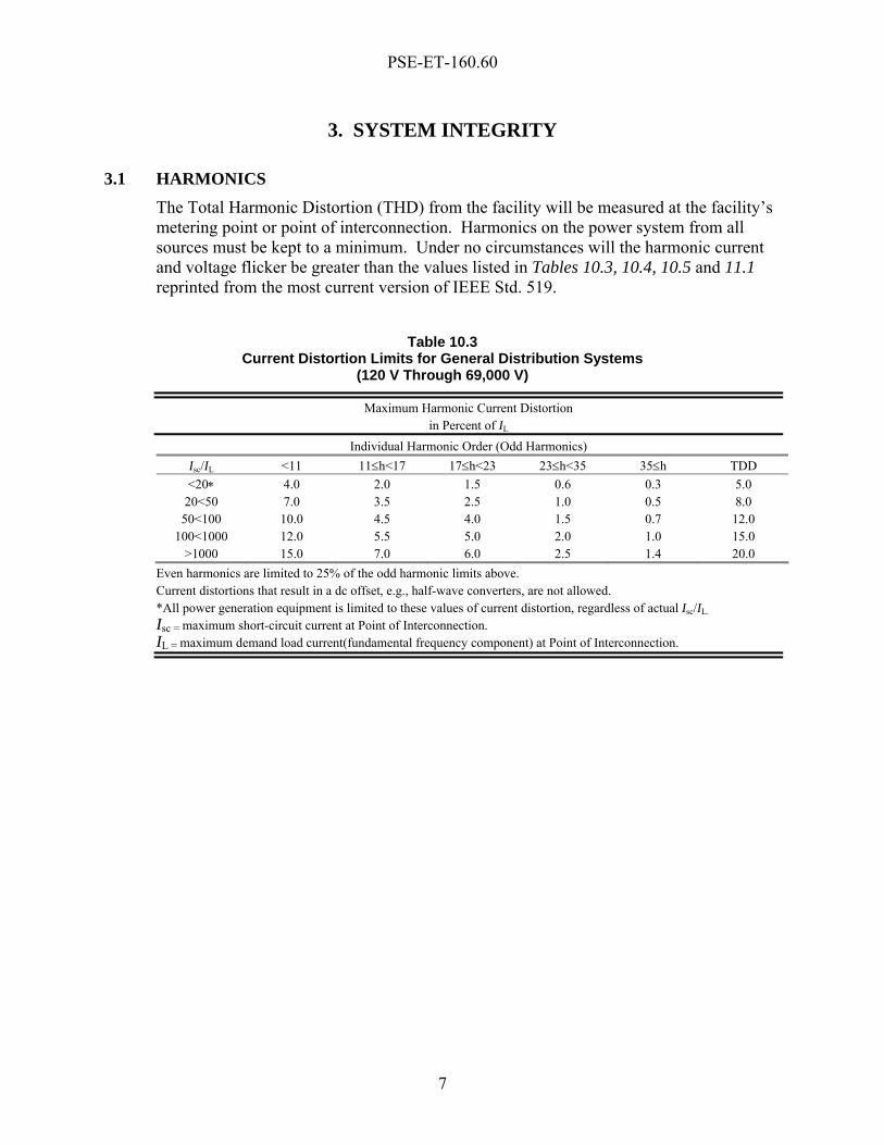
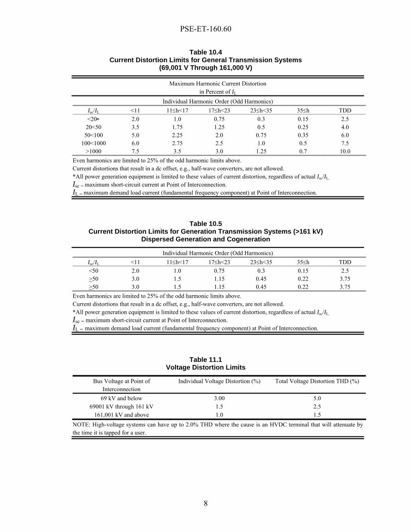
3.1 HARMONICS The Total Harmonic Distortion (THD) from the facility will be measured at the facility’s metering point or point of interconnection. Harmonics on the power system from all sources must be kept to a minimum. Under no circumstances will the harmonic current and voltage flicker be greater than the values listed in Tables 10.3, 10.4, 10.5 and 11.1 reprinted from the most current version of IEEE Std. 519.
Table 10.3
Current Distortion Limits for General Distribution Systems (120 V Through 69,000 V)
Maximum Harmonic Current Distortion in Percent of IL
Individual Harmonic Order (Odd Harmonics) Isc/IL <11 11≤h<17 17≤h<23 23≤h<35 35≤h TDD <20∗ 4.0 2.0 1.5 0.6 0.3 5.0
20<50 7.0 3.5 2.5 1.0 0.5 8.0 50<100 10.0 4.5 4.0 1.5 0.7 12.0
100<1000 12.0 5.5 5.0 2.0 1.0 15.0 >1000 15.0 7.0 6.0 2.5 1.4 20.0
Even harmonics are limited to 25% of the odd harmonic limits above. Current distortions that result in a dc offset, e.g., half-wave converters, are not allowed. *All power generation equipment is limited to these values of current distortion, regardless of actual Isc/IL. Isc = maximum short-circuit current at Point of Interconnection. IL = maximum demand load current(fundamental frequency component) at Point of Interconnection.
PSE-ET-160.60
8
Table 10.4 Current Distortion Limits for General Transmission Systems
(69,001 V Through 161,000 V)
Maximum Harmonic Current Distortion in Percent of IL
Individual Harmonic Order (Odd Harmonics) Isc/IL <11 11≤h<17 17≤h<23 23≤h<35 35≤h TDD <20∗ 2.0 1.0 0.75 0.3 0.15 2.5
20<50 3.5 1.75 1.25 0.5 0.25 4.0 50<100 5.0 2.25 2.0 0.75 0.35 6.0
100<1000 6.0 2.75 2.5 1.0 0.5 7.5 >1000 7.5 3.5 3.0 1.25 0.7 10.0
Even harmonics are limited to 25% of the odd harmonic limits above. Current distortions that result in a dc offset, e.g., half-wave converters, are not allowed. *All power generation equipment is limited to these values of current distortion, regardless of actual Isc/IL.
Isc = maximum short-circuit current at Point of Interconnection. IL = maximum demand load current (fundamental frequency component) at Point of Interconnection.
Table 10.5 Current Distortion Limits for Generation Transmission Systems (>161 kV)
Dispersed Generation and Cogeneration
Individual Harmonic Order (Odd Harmonics) Isc/IL <11 11≤h<17 17≤h<23 23≤h<35 35≤h TDD <50 2.0 1.0 0.75 0.3 0.15 2.5 >50 3.0 1.5 1.15 0.45 0.22 3.75 >50 3.0 1.5 1.15 0.45 0.22 3.75
Even harmonics are limited to 25% of the odd harmonic limits above. Current distortions that result in a dc offset, e.g., half-wave converters, are not allowed. *All power generation equipment is limited to these values of current distortion, regardless of actual Isc/IL. Isc = maximum short-circuit current at Point of Interconnection. IL = maximum demand load current (fundamental frequency component) at Point of Interconnection.
Table 11.1 Voltage Distortion Limits
Bus Voltage at Point of Interconnection
Individual Voltage Distortion (%) Total Voltage Distortion THD (%)
69 kV and below 3.00 5.0 69001 kV through 161 kV 1.5 2.5
161,001 kV and above 1.0 1.5 NOTE: High-voltage systems can have up to 2.0% THD where the cause is an HVDC terminal that will attenuate by the time it is tapped for a user.
PSE-ET-160.60
9
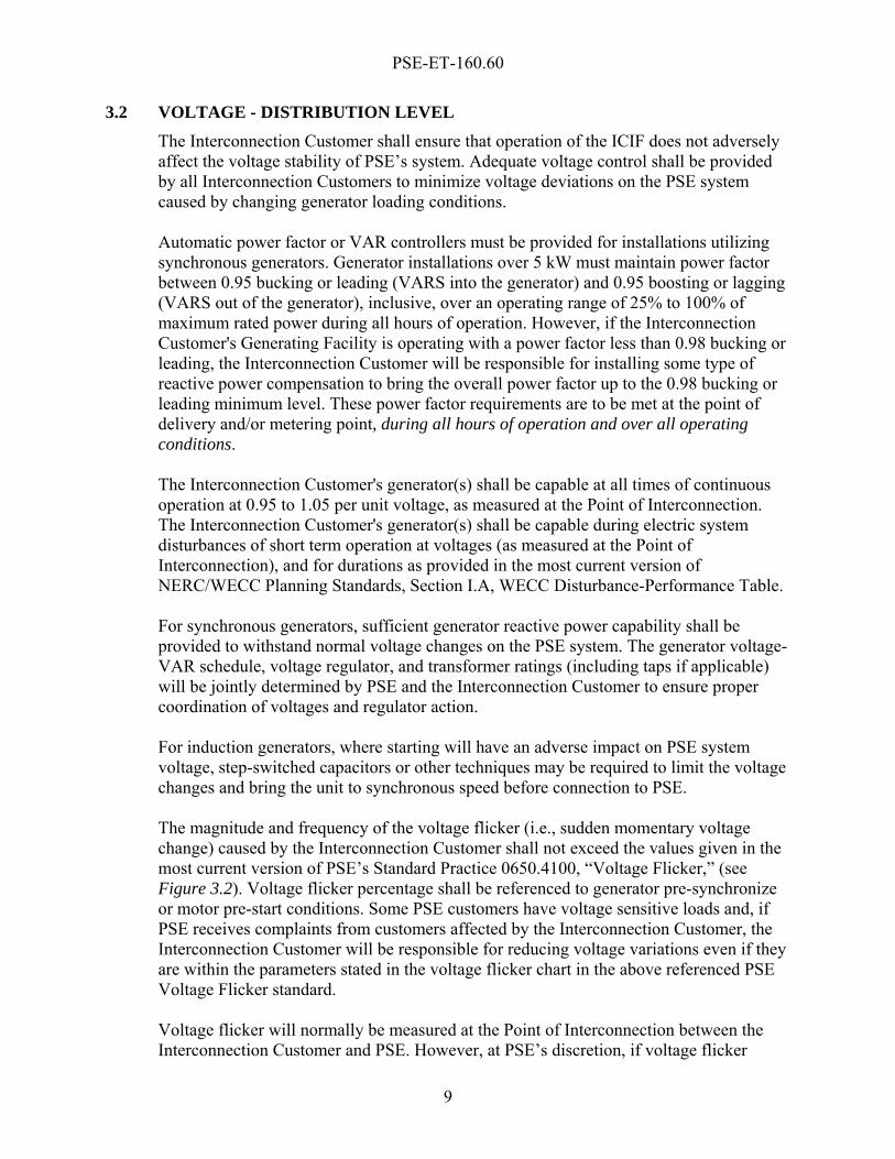
3.2 VOLTAGE - DISTRIBUTION LEVEL The Interconnection Customer shall ensure that operation of the ICIF does not adversely affect the voltage stability of PSE’s system. Adequate voltage control shall be provided by all Interconnection Customers to minimize voltage deviations on the PSE system caused by changing generator loading conditions. Automatic power factor or VAR controllers must be provided for installations utilizing synchronous generators. Generator installations over 5 kW must maintain power factor between 0.95 bucking or leading (VARS into the generator) and 0.95 boosting or lagging (VARS out of the generator), inclusive, over an operating range of 25% to 100% of maximum rated power during all hours of operation. However, if the Interconnection Customer's Generating Facility is operating with a power factor less than 0.98 bucking or leading, the Interconnection Customer will be responsible for installing some type of reactive power compensation to bring the overall power factor up to the 0.98 bucking or leading minimum level. These power factor requirements are to be met at the point of delivery and/or metering point, during all hours of operation and over all operating conditions. The Interconnection Customer's generator(s) shall be capable at all times of continuous operation at 0.95 to 1.05 per unit voltage, as measured at the Point of Interconnection. The Interconnection Customer's generator(s) shall be capable during electric system disturbances of short term operation at voltages (as measured at the Point of Interconnection), and for durations as provided in the most current version of NERC/WECC Planning Standards, Section I.A, WECC Disturbance-Performance Table. For synchronous generators, sufficient generator reactive power capability shall be provided to withstand normal voltage changes on the PSE system. The generator voltage-VAR schedule, voltage regulator, and transformer ratings (including taps if applicable) will be jointly determined by PSE and the Interconnection Customer to ensure proper coordination of voltages and regulator action. For induction generators, where starting will have an adverse impact on PSE system voltage, step-switched capacitors or other techniques may be required to limit the voltage changes and bring the unit to synchronous speed before connection to PSE. The magnitude and frequency of the voltage flicker (i.e., sudden momentary voltage change) caused by the Interconnection Customer shall not exceed the values given in the most current version of PSE’s Standard Practice 0650.4100, “Voltage Flicker,” (see Figure 3.2). Voltage flicker percentage shall be referenced to generator pre-synchronize or motor pre-start conditions. Some PSE customers have voltage sensitive loads and, if PSE receives complaints from customers affected by the Interconnection Customer, the Interconnection Customer will be responsible for reducing voltage variations even if they are within the parameters stated in the voltage flicker chart in the above referenced PSE Voltage Flicker standard. Voltage flicker will normally be measured at the Point of Interconnection between the Interconnection Customer and PSE. However, at PSE’s discretion, if voltage flicker
PSE-ET-160.60
10
problems are found, the measurement may be taken at the nearest possible present or future PSE customer. The voltage flicker chart does not address the time duration of the voltage drop. For the purposes of this section, a drop of any duration shall be considered as a single occurrence. Such a voltage drop may be acceptable after consultation with PSE, but the Interconnection Customer is responsible for any associated damage caused to the equipment or lost productivity of other PSE customers. It is advised that Interconnection Customers review the most current version of IEEE/ANSI Standard 141 (Red Book) for typical computer sensitivity to very short voltage disturbances.
Figure 3.2. Range of observable and objectionable voltage flicker versus time,
from PSE Standard 0650.4100
3.3 VOLTAGE - TRANSMISSION LEVEL The Interconnection Customer shall ensure that operation of the ICIF does not adversely affect the voltage stability of PSE’s system. Adequate voltage control shall be provided by all Interconnection Customers to minimize voltage deviations on the PSE system caused by changing generator loading conditions. For synchronous generators, sufficient generator reactive power capability shall be provided to withstand normal voltage changes on the PSE system. The generator
PSE-ET-160.60
11
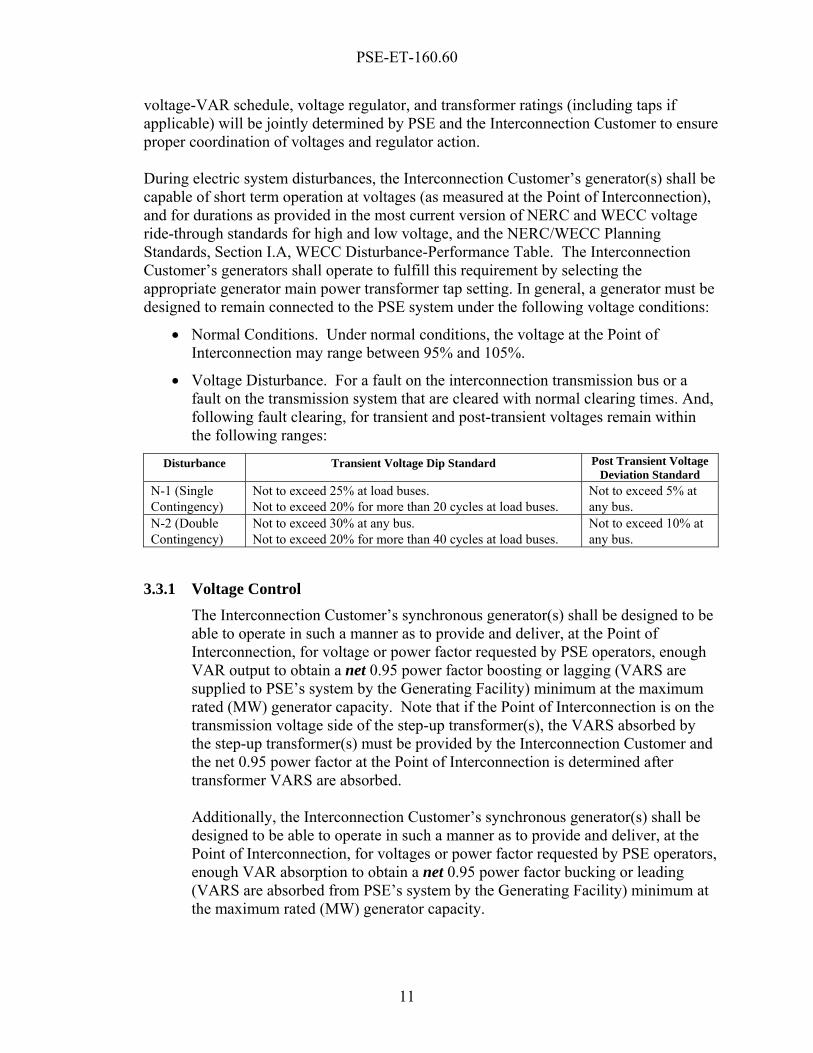
voltage-VAR schedule, voltage regulator, and transformer ratings (including taps if applicable) will be jointly determined by PSE and the Interconnection Customer to ensure proper coordination of voltages and regulator action. During electric system disturbances, the Interconnection Customer’s generator(s) shall be capable of short term operation at voltages (as measured at the Point of Interconnection), and for durations as provided in the most current version of NERC and WECC voltage ride-through standards for high and low voltage, and the NERC/WECC Planning Standards, Section I.A, WECC Disturbance-Performance Table. The Interconnection Customer’s generators shall operate to fulfill this requirement by selecting the appropriate generator main power transformer tap setting. In general, a generator must be designed to remain connected to the PSE system under the following voltage conditions:
• Normal Conditions. Under normal conditions, the voltage at the Point of Interconnection may range between 95% and 105%.
• Voltage Disturbance. For a fault on the interconnection transmission bus or a fault on the transmission system that are cleared with normal clearing times. And, following fault clearing, for transient and post-transient voltages remain within the following ranges:
Disturbance Transient Voltage Dip Standard Post Transient Voltage Deviation Standard
N-1 (Single Contingency)
Not to exceed 25% at load buses. Not to exceed 20% for more than 20 cycles at load buses.
Not to exceed 5% at any bus.
N-2 (Double Contingency)
Not to exceed 30% at any bus. Not to exceed 20% for more than 40 cycles at load buses.
Not to exceed 10% at any bus.
3.3.1 Voltage Control The Interconnection Customer’s synchronous generator(s) shall be designed to be able to operate in such a manner as to provide and deliver, at the Point of Interconnection, for voltage or power factor requested by PSE operators, enough VAR output to obtain a net 0.95 power factor boosting or lagging (VARS are supplied to PSE’s system by the Generating Facility) minimum at the maximum rated (MW) generator capacity. Note that if the Point of Interconnection is on the transmission voltage side of the step-up transformer(s), the VARS absorbed by the step-up transformer(s) must be provided by the Interconnection Customer and the net 0.95 power factor at the Point of Interconnection is determined after transformer VARS are absorbed.
Additionally, the Interconnection Customer’s synchronous generator(s) shall be designed to be able to operate in such a manner as to provide and deliver, at the Point of Interconnection, for voltages or power factor requested by PSE operators, enough VAR absorption to obtain a net 0.95 power factor bucking or leading (VARS are absorbed from PSE’s system by the Generating Facility) minimum at the maximum rated (MW) generator capacity.
PSE-ET-160.60
12
3.3.2 Wind Power Induction Generating Facilities Under certain conditions, a self-excited induction generator can produce abnormally high voltages that can cause damage to the equipment of other Interconnection Customers and other customers. Overvoltage relays can limit the duration of such overvoltages but cannot control their magnitude. Because of these problems, the reactive power supply for large induction generators must be studied on an individual basis. In general, self-excitation problems are most likely in rural areas where the PSE system capacity and load density are low. Where self-excitation problems appear likely, special service arrangements will be required. PSE requires the following power factors for wind power Generating Facilities:
1. At the Point of Interconnection of the wind power Generating Facility to the
PSE system:
• The wind power Generating Facility shall have a reactive power compensation scheme, sized to provide and control between a net 0.98 power factor bucking or leading and a net 0.95 power factor boosting or lagging at maximum generation output at the Point of Interconnection to the PSE system.
• The switching and control of the reactive power shall be done in small enough increments to limit the change in reactive power production or absorption in steady state to steps of no more than 10% of the generated power.
2. Capacitors shall be installed to maintain a power factor of at least 0.98 over a
range of 25% to 100% of output rating. The following capacitor banks will be required to compensate the large reactive loads created by wind induction generators:
• Several steps of capacitor banks for each generator at generator voltage, and
• Capacitor banks at the collector feeder voltage and located at the substation to compensate the reactive losses in the substation transformers connected at the Point of Interconnection to the PSE system, and for transmission voltage regulation.
3. To ensure adherence to the power factor correction criteria, the wind power
Generating Facility developer will be required to perform VAR accounting for all generator loading levels to determine size of capacitor bank at the collector feeder voltage at the substation connected to the PSE System in order to ensure that the wind power Generating Facility meets the power factor criteria defined above.
PSE-ET-160.60
13
4. GENERAL DESIGN REQUIREMENTS
4.1 DISCONNECTING DEVICES Any switch or other disconnecting device installed by the Interconnection Customer pursuant to Section 9.7.5 of the SGIA must be operable by PSE, must be accessible to PSE at all times, and must be lockable in the open position with PSE’s standard padlock. For three-phase installations, gang-operated three pole switches must be installed. Each switch or other disconnecting device shall comply with the most current versions of PSE Standard Specifications 1300.2100 and 1300.2300. Any interconnection breaker shall comply with the most current version of PSE Standard Specification 1300.4000.
4.2 INTERRUPTING DEVICES Any interrupting device installed by the Interconnection Customer must be adequately rated for the available short circuit current. PSE will provide short-circuit data to the customer for use in calculating the required interrupting rating as part of the System Impact Study.
4.3 STEP AND TOUCH POTENTIAL It is the Interconnection Customer’s responsibility to ensure that the step and touch potentials meet the most current version of IEEE Std. 80 and that construction complies with National Electrical Safety Code (NESC).
4.4 INSULATION COORDINATION In general, stations with equipment operated at 15 kV and above, as well as all transformers and reactors, shall be protected against lightning and switching surges. Typically this includes station shielding against direct lightning strokes, surge arresters on all transformers, reactors, and surge protection with rod gaps (or arresters) on the incoming lines.
4.5 CONTROL REQUIREMENTS Outputs or interposing relays controlled by programmable logic controls shall not be in series with the interconnection tripping relays and breaker trip coils. All interconnection protection relays shall be capable of tripping the breakers. All interconnection protection shall be powered by station battery DC voltage and must include a DC undervoltage detection device and alarm. The station battery design shall be in compliance with the most current version of IEEE Std. 485.
PSE-ET-160.60
14
4.6 EFFECTIVE GROUNDING It is the Interconnection Customer’s responsibility to ensure that its system is effectively grounded at the point of interconnection. As defined by IEEE Std. 142, an effectively grounded system requires that X0/X1 <3 and R0/X1 < 1.
4.7 EXCITATION EQUIPMENT, INCLUDING POWER SYSTEM STABILIZERS - TRANSMISSION CONNECTED GENERATING FACILITIES Excitation equipment includes the exciter, automatic voltage regulator, power system stabilizer and over-excitation limiter. The following NERC/WECC Planning Standards, Section III.C, shall be observed:
S1 - All synchronous generators connected to the interconnected transmission systems shall be operated with their excitation system in the automatic voltage control mode unless approved otherwise by the transmission system operator. (The intent is that continuous automatic voltage control not be overridden by supplementary power factor or reactive power controls.) S2 - Generators shall maintain a network voltage or reactive power output as required by the transmission system operator within the reactive capability of the units. Generator step-up and auxiliary transformers shall have their tap settings coordinated with the electric system voltage requirements. S4 - Voltage regulator controls and limit functions (such as over and under excitation and volts/hertz limiters) shall coordinate with the generator’s short duration capabilities and protective relays.
The excitation system ceiling voltage shall be at least 150 percent of the rated field voltage. The excitation system must be capable of maintaining no less than 150% of rated field voltage at 70% synchronous machine terminal voltage. The excitation system ceiling current shall have a short time capability no less than the short time thermal overload capability of the synchronous machine field winding. Automatic voltage regulators (AVRs) should be continuously acting solid state analog or digital. Tuning should be in accordance with NERC/WECC Planning Standard Section II.C, G8 reproduced below. Tuning results should be included in commissioning test reports provided to PSE.
G8 - Generator voltage regulators to extent practical should be tuned for fast response to step changes in terminal voltage or voltage reference. It is preferable to run the step change in voltage tests with the generator not connected to the system so as to eliminate the system effects on the generator voltage. Terminal voltage overshoot should generally not exceed 10% for an open circuit step change in voltage test.

PSE-ET-160.60
15
New generators that are connected by a generator step-up transformer to the PSE system at a voltage of 60 kV or higher shall have power system stabilizers, and shall tune and operate them according to the requirements of “WECC Policy Statement on Power System Stabilizers.” The Policy defines exceptions and suitability requirements. Generating Facilities that are less than or equal to 30 MVA are exempt from such requirements, unless they are part of a complex with an aggregate capacity larger than 75 MVA. Every power system stabilizer shall operate in-service at all times the Interconnection Customer’s Generating Facility is connected to the PSE system, except for reasons given in the “WECC Policy Statement on Power System Stabilizers.” The voltage regulator shall include an overexcitation limiter. The overexcitation limiter shall be of the inverse-time type adjusted to coordinate with the generator field circuit time-overcurrent capability. Operation of the limiter shall cause a reduction of field current from the continuous field current capability. Full automatic voltage regulation shall automatically be restored when system conditions allow field current within the continuous rating.
4.8 GOVERNOR REQUIREMENTS - TRANSMISSION CONNECTED GENERATING FACILITIES All unit governors shall be operated in automatic with droop set as stated in the WECC, Part III, Minimum Operating Reliability Criteria, December 2000, Section 1.C.2 Frequency, Response and Bias, Governors (or as otherwise provided in its most current standard). Governor deadbands shall meet the requirements of NERC/WECC Operating Standard Policy 1, which states:
“Governors should, as a minimum, be fully responsive to frequency deviations exceeding +/- 0.036 Hz (+/-36mHz).”
4.9 INDUCTION GENERATORS Installations over 5 kW capacity will require capacitors to be installed to maintain a power factor of at least 0.95 over a range of 25% to 100% of output rating (see Section 3.3). Such capacitor installation will be at the expense of the Interconnection Customer. Under certain conditions, a self-excited induction generator can produce abnormally high voltages that can cause damage to the equipment of other Interconnection Customers and other customers. Overvoltage relays can limit the duration of such overvoltages but cannot control their magnitude. Because of these problems, the reactive power supply for large induction generators must be studied on an individual basis. In general, self-excitation problems are most likely in rural areas where the PSE system capacity and load density are low.

PSE-ET-160.60
16
It is particularly important for the Interconnection Customer to contact PSE to determine if an induction generator can be connected to an existing distribution line. Where self-excitation problems appear likely, special service arrangements will be required.
4.10 INVERTER SYSTEMS Since inverters can be a harmonic source, the Interconnection Customer shall strictly comply with Section 3.1.
4.11 WIND POWER GENERATING FACILITIES Wind power Generating Facility developers must follow the “Utility Interconnection” requirements defined in IEEE Standard 1094-1991 (IEEE Recommended Practice for the Electrical Design and Operation of Windfarm Generating Stations). Developers must provide wind turbine detailed technical data for each wind turbine type to be installed at the wind power Generating Facility.
4.11.1 Production Control The control for wind power Generating Facilities must limit production as follows:
• The production, determined as a one-minute average value, must not at any time exceed the production limit by more than five percent of the maximum power of the wind power Generating Facility.
• The production limit must be able to be controlled by a single central signal. The control shall be arranged individually for each wind power Generating Facility and control algorithms must be capable of being changed at a later time.
• The control shall take place at the individual wind turbine, and production control must be capable of reduction to below 20 percent of the maximum power in less than two seconds.
• High wind speed must not cause more than 20 percent of the Generating Facilities’ turbines to stop simultaneously.
• Each generating unit must be capable of controlling power changes to 1 percent or less of the rated power per minute across the entire range between minimum power and maximum power.
PSE-ET-160.60
17
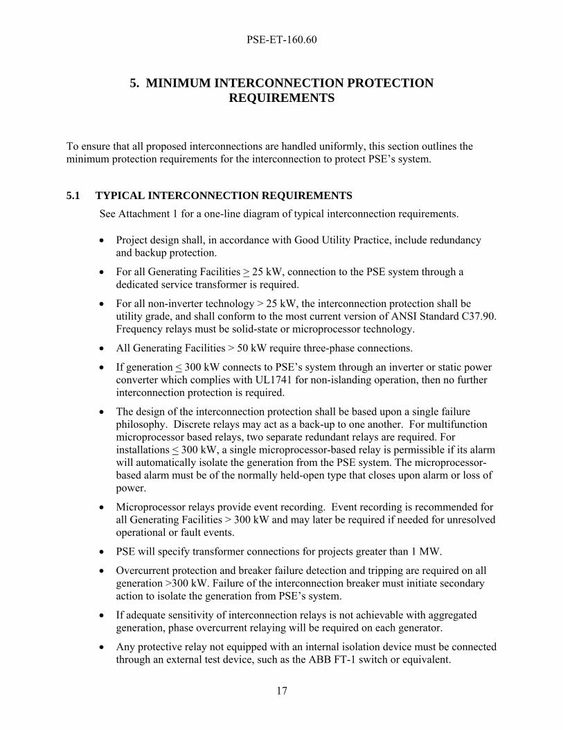
5. MINIMUM INTERCONNECTION PROTECTION REQUIREMENTS
To ensure that all proposed interconnections are handled uniformly, this section outlines the minimum protection requirements for the interconnection to protect PSE’s system.
5.1 TYPICAL INTERCONNECTION REQUIREMENTS See Attachment 1 for a one-line diagram of typical interconnection requirements. • Project design shall, in accordance with Good Utility Practice, include redundancy
and backup protection.
• For all Generating Facilities > 25 kW, connection to the PSE system through a dedicated service transformer is required.
• For all non-inverter technology > 25 kW, the interconnection protection shall be utility grade, and shall conform to the most current version of ANSI Standard C37.90. Frequency relays must be solid-state or microprocessor technology.
• All Generating Facilities > 50 kW require three-phase connections.
• If generation < 300 kW connects to PSE’s system through an inverter or static power converter which complies with UL1741 for non-islanding operation, then no further interconnection protection is required.
• The design of the interconnection protection shall be based upon a single failure philosophy. Discrete relays may act as a back-up to one another. For multifunction microprocessor based relays, two separate redundant relays are required. For installations < 300 kW, a single microprocessor-based relay is permissible if its alarm will automatically isolate the generation from the PSE system. The microprocessor-based alarm must be of the normally held-open type that closes upon alarm or loss of power.
• Microprocessor relays provide event recording. Event recording is recommended for all Generating Facilities > 300 kW and may later be required if needed for unresolved operational or fault events.
• PSE will specify transformer connections for projects greater than 1 MW.
• Overcurrent protection and breaker failure detection and tripping are required on all generation >300 kW. Failure of the interconnection breaker must initiate secondary action to isolate the generation from PSE’s system.
• If adequate sensitivity of interconnection relays is not achievable with aggregated generation, phase overcurrent relaying will be required on each generator.
• Any protective relay not equipped with an internal isolation device must be connected through an external test device, such as the ABB FT-1 switch or equivalent.
PSE-ET-160.60
18
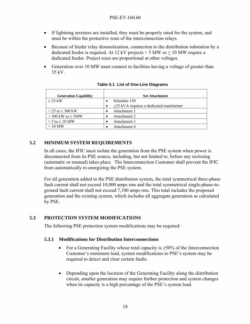
• If lightning arresters are installed, they must be properly rated for the system, and must be within the protective zone of the interconnection relays.
• Because of feeder relay desensitization, connection to the distribution substation by a dedicated feeder is required. At 12 kV projects > 5 MW or < 10 MW require a dedicated feeder. Project sizes are proportional at other voltages.
• Generation over 10 MW must connect to facilities having a voltage of greater than 35 kV.
Table 5.1 List of One-Line Diagrams
Generation Capability
See Attachment ≤ 25 kW • Schedule 150
• >25 kVA requires a dedicated transformer > 25 to ≤ 300 kW • Attachment 1 > 300 kW to ≤ 5MW • Attachment 2 > 5 to ≤ 10 MW • Attachment 3 > 10 MW • Attachment 4
5.2 MINIMUM SYSTEM REQUIREMENTS In all cases, the IFIC must isolate the generation from the PSE system when power is disconnected from its PSE source, including, but not limited to, before any reclosing (automatic or manual) takes place. The Interconnection Customer shall prevent the IFIC from automatically re-energizing the PSE system. For all generation added to the PSE distribution system, the total symmetrical three-phase fault current shall not exceed 10,000 amps rms and the total symmetrical single-phase-to-ground fault current shall not exceed 7,100 amps rms. This total includes the proposed generation and the existing system, which includes all aggregate generation as calculated by PSE.
5.3 PROTECTION SYSTEM MODIFICATIONS The following PSE protection system modifications may be required:
5.3.1 Modifications for Distribution Interconnections
• For a Generating Facility whose total capacity is ≥50% of the Interconnection Customer’s minimum load, system modifications to PSE’s system may be required to detect and clear certain faults.
• Depending upon the location of the Generating Facility along the distribution circuit, smaller generation may require further protection and system changes when its capacity is a high percentage of the PSE’s system load.
PSE-ET-160.60
19
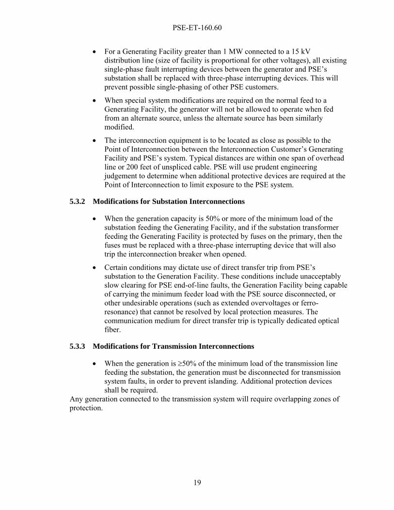
• For a Generating Facility greater than 1 MW connected to a 15 kV distribution line (size of facility is proportional for other voltages), all existing single-phase fault interrupting devices between the generator and PSE’s substation shall be replaced with three-phase interrupting devices. This will prevent possible single-phasing of other PSE customers.
• When special system modifications are required on the normal feed to a Generating Facility, the generator will not be allowed to operate when fed from an alternate source, unless the alternate source has been similarly modified.
• The interconnection equipment is to be located as close as possible to the Point of Interconnection between the Interconnection Customer’s Generating Facility and PSE’s system. Typical distances are within one span of overhead line or 200 feet of unspliced cable. PSE will use prudent engineering judgement to determine when additional protective devices are required at the Point of Interconnection to limit exposure to the PSE system.
5.3.2 Modifications for Substation Interconnections
• When the generation capacity is 50% or more of the minimum load of the substation feeding the Generating Facility, and if the substation transformer feeding the Generating Facility is protected by fuses on the primary, then the fuses must be replaced with a three-phase interrupting device that will also trip the interconnection breaker when opened.
• Certain conditions may dictate use of direct transfer trip from PSE’s substation to the Generation Facility. These conditions include unacceptably slow clearing for PSE end-of-line faults, the Generation Facility being capable of carrying the minimum feeder load with the PSE source disconnected, or other undesirable operations (such as extended overvoltages or ferro- resonance) that cannot be resolved by local protection measures. The communication medium for direct transfer trip is typically dedicated optical fiber.
5.3.3 Modifications for Transmission Interconnections
• When the generation is ≥50% of the minimum load of the transmission line feeding the substation, the generation must be disconnected for transmission system faults, in order to prevent islanding. Additional protection devices shall be required.
Any generation connected to the transmission system will require overlapping zones of protection.


PSE-ET-160.60
21
6. METERING: PSE REVENUE, OPERATIONS AND SCHEDULING REQUIREMENTS
6.1 GENERAL Metering may be required for revenue purposes, System Operations purposes, or both, depending on the specifics of the project. Revenue metering is required for the measurement of any function that will be billed under a PSE Scheduled Tariff. The Washington Administrative Code (WAC) requires that revenue metering be owned and operated by PSE, and that it meets stringent accuracy requirements. Even if revenue metering is not required on a project initially, it is often advisable, during the planning and construction of interconnection facilities, to include all the provisions for the possibility of future installation of PSE-owned revenue metering as retrofit installation at a later date can be extremely costly and complicated compared to the incremental cost of including those provisions during the initial construction. Systems Operation metering is used for dispatching, reserves, accounting, and control of the PSE Transmission and Distribution systems. Whether or not System Operations metering is required is the sole discretion of PSE. Often, the revenue metering can also be used to provide meter data for system operations, which is the most cost effective solution when both metering systems are necessary. If System Operations metering is required but revenue metering is not required, it may be possible for the System Operation metering to be customer-owned as Systems Operation metering does not fall under the WAC. Systems Operation metering that is customer-owned must be reviewed in advance by the PSE Electric Meter Engineering Department for function and accuracy. Accuracy must be within +/- 1.0%.
6.2 REVENUE METERING
In general, Revenue Metering installation requirements for the different categories of the Interconnection Customer-owned parallel generators are the same as those outlined in PSE’s Electric Service Handbook for Commercial/Industrial/Multifamily & Manufactured Housing Developments (PSE Standards 6325.3000-3360). In addition to the PSE Handbook, metering installations shall comply with the requirements of the Electric Utility Service Entrance Requirement Committee (EUSERC), Section 300 or 400, as appropriate. PSE will provide a current one page EUSERC acceptability summary. Preferably, the metering will be located on PSE's side of ownership of the electric facilities and the metering voltage shall normally be the same voltage as the Point of Interconnection for the Generating Facility output. If the voltage at the Point of Interconnection exceeds 15 kV, metering may be installed at the low side of the step-up transformer. In this case, loss compensation shall be applied at the meter to adjust for
PSE-ET-160.60
22
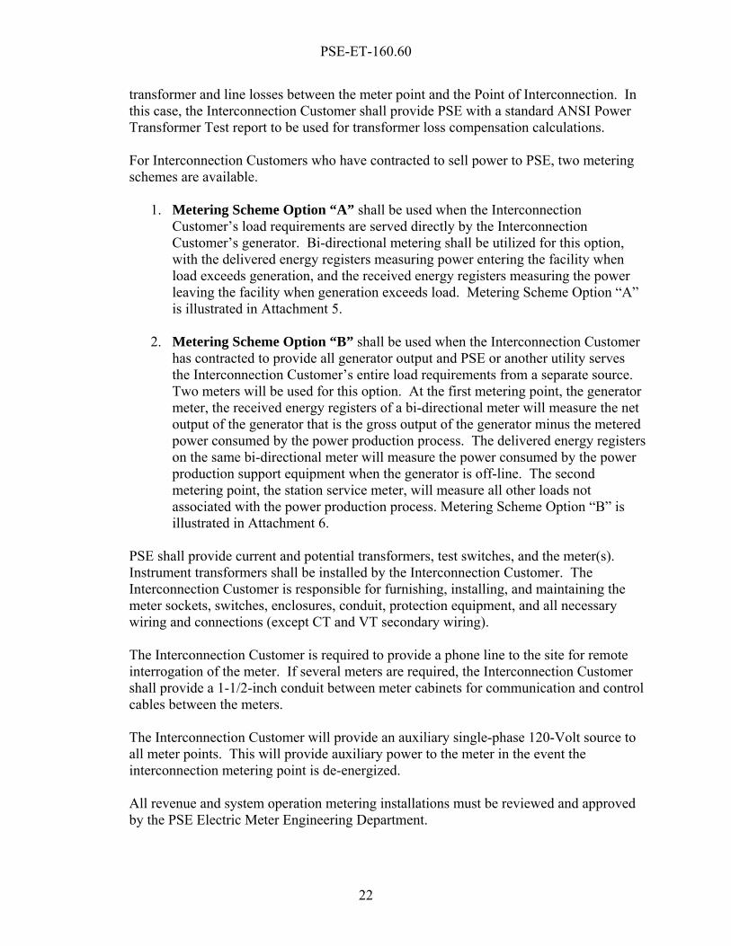
transformer and line losses between the meter point and the Point of Interconnection. In this case, the Interconnection Customer shall provide PSE with a standard ANSI Power Transformer Test report to be used for transformer loss compensation calculations. For Interconnection Customers who have contracted to sell power to PSE, two metering schemes are available.
1. Metering Scheme Option “A” shall be used when the Interconnection
Customer’s load requirements are served directly by the Interconnection Customer’s generator. Bi-directional metering shall be utilized for this option, with the delivered energy registers measuring power entering the facility when load exceeds generation, and the received energy registers measuring the power leaving the facility when generation exceeds load. Metering Scheme Option “A” is illustrated in Attachment 5.
2. Metering Scheme Option “B” shall be used when the Interconnection Customer has contracted to provide all generator output and PSE or another utility serves the Interconnection Customer’s entire load requirements from a separate source. Two meters will be used for this option. At the first metering point, the generator meter, the received energy registers of a bi-directional meter will measure the net output of the generator that is the gross output of the generator minus the metered power consumed by the power production process. The delivered energy registers on the same bi-directional meter will measure the power consumed by the power production support equipment when the generator is off-line. The second metering point, the station service meter, will measure all other loads not associated with the power production process. Metering Scheme Option “B” is illustrated in Attachment 6.
PSE shall provide current and potential transformers, test switches, and the meter(s). Instrument transformers shall be installed by the Interconnection Customer. The Interconnection Customer is responsible for furnishing, installing, and maintaining the meter sockets, switches, enclosures, conduit, protection equipment, and all necessary wiring and connections (except CT and VT secondary wiring). The Interconnection Customer is required to provide a phone line to the site for remote interrogation of the meter. If several meters are required, the Interconnection Customer shall provide a 1-1/2-inch conduit between meter cabinets for communication and control cables between the meters. The Interconnection Customer will provide an auxiliary single-phase 120-Volt source to all meter points. This will provide auxiliary power to the meter in the event the interconnection metering point is de-energized. All revenue and system operation metering installations must be reviewed and approved by the PSE Electric Meter Engineering Department.
PSE-ET-160.60
23
6.3 RTU (REMOTE TERMINAL UNIT) AND TELEMETRY METERING Balancing Authorities, such as the one operated by PSE, are required to meet NERC, WECC and NWPP operating policies and to conform to Good Utility Practices. One such requirement is to have generating reserves per the WECC Minimum Operating Reliability Criteria and the NWPP Reserve Sharing Procedure. These reserves include regulating, contingency spinning, and contingency non-spinning. For System Operations generation RTU and telemetry metering is needed to manage reserves and to account for contingency load obligations. This section deals with those requirements.
6.3.1 Generator Sites With A Combined Output Less Than 2 MW Real time monitoring is not required for generator sites having a combined output of less than 2 MW. Also, real time monitoring is not required for generators that do not operate in parallel with PSE’s system. For the purpose of this Standard, this includes standby generation intended for emergency use only, and generators connected to the system momentarily via closed transition switching (100 ms or less).
6.3.2 Generator Sites With A Combined Output of 2 MW or Greater Real-time monitoring data is required for generation sources with a combined output of 2 MW or greater. This data is sent from the generator site to PSE’s Operating Center using RTU and telemetry equipment. A dedicated communication circuit (e.g., leased line) is required to transmit such data. Generation values are transmitted continuously from the source to the Operating Center and hourly accumulations are calculated at the end of each hour for Balancing Authority accounting purposes. These generation values are used for Automatic Generation Control (“AGC”), reserves calculations, forecasting, and for Balancing Authority energy accounting. If applicable, PSE may require indication of the spinning reserve available and for reserves under control. The following includes specific requirements:
• Meter values sent via RTU and telemetry include real power (MW), energy (MWh) and reactive power (kVAR).
• Totalizing metering quantities from multiple generators at one site is desirable in most cases.
• PSE will determine telemetry requirements for temporary generators (12 months or less) on a case-by-case basis. Energy Pre-Scheduling may be used as an alternative to telemetry for temporary sites.
• Both RTU and telemetry require one or more dedicated communication circuits between the project and the PSE operating center.
PSE-ET-160.60
24
• Reasonable access must be provided by the Interconnection Customer to PSE for installation, testing, and repair of the RTU equipment, telemetry equipment, and circuits.
• The design, purchase, installation, testing, maintenance, and replacement of the remote generation RTU and telemetry equipment, and circuits from the Interconnection Customer’s facility to PSE’s AGC Dispatch Center, will be the responsibility of the Interconnection Customer.
6.4 GENERATION SCHEDULING REQUIREMENTS Interconnected generation that is either temporary or permanent and equal to or greater than 2 MW shall be prescheduled for each hour using PSE’s normal scheduling procedures. The preschedule shows hourly generation plans on a 7-day (168-hour) advance time period, and is updated weekly or as conditions change. If prescheduled generation is taken off line for any reason, the Interconnection Customer shall notify PSE’s 24-hour generation dispatcher with an updated generation schedule.
6.5 EXPORTING ENERGY All transmission or distribution arrangements for exporting energy off-site, either within, across, or out of the PSE Balancing Area, requires prescheduling along with metering and telemetry equipment. For applicable rules and procedures for transporting energy see PSE’s Open Access Tariff (OATT).
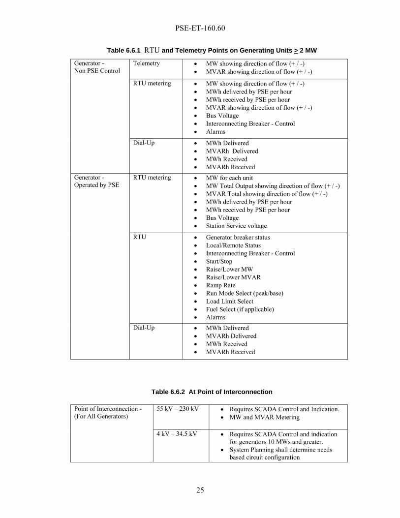
6.6 SCADA, RTU AND TELEMETRY REQUIREMENTS The general RTU and telemetry requirements from the Interconnection Customer to PSE are provided for each generating unit greater than or equal to 2 MW in Table 6.6.1, and such requirements for the Point of Interconnection are provided in Table 6.6.2.
SCADA for breaker status is required for the Point of Interconnection between PSE and the Interconnection Customer’s generators when generators are dispatchable and connected to PSE’s transmission system. PSE’s 24-Hour Operating Center must have the ability to disconnect the Generating Facility from PSE’s system via SCADA for sites that are 10 MW or greater. Switching procedures for disconnecting the Generating Facility will vary depending upon the bus configuration.
Each wind power Generating Facility shall also provide a signal to PSE showing the status of the Generating Facility, such as whether power production has stopped due to lack of wind, too much wind, forced outage, or by external control. Together with signals from the PSE system operator and local measurements (for instance voltage, frequency and wind speed) these signals shall be part of a control system managing the release of the wind turbines for operation.
PSE-ET-160.60
25
Table 6.6.1 RTU and Telemetry Points on Generating Units > 2 MW
Telemetry • MW showing direction of flow (+ / -) • MVAR showing direction of flow (+ / -)
RTU metering • MW showing direction of flow (+ / -) • MWh delivered by PSE per hour • MWh received by PSE per hour • MVAR showing direction of flow (+ / -) • Bus Voltage • Interconnecting Breaker - Control • Alarms
Generator - Non PSE Control
Dial-Up • MWh Delivered • MVARh Delivered • MWh Received • MVARh Received
RTU metering • MW for each unit • MW Total Output showing direction of flow (+ / -) • MVAR Total showing direction of flow (+ / -) • MWh delivered by PSE per hour • MWh received by PSE per hour • Bus Voltage • Station Service voltage
RTU • Generator breaker status • Local/Remote Status • Interconnecting Breaker - Control • Start/Stop • Raise/Lower MW • Raise/Lower MVAR • Ramp Rate • Run Mode Select (peak/base) • Load Limit Select • Fuel Select (if applicable) • Alarms
Generator - Operated by PSE
Dial-Up • MWh Delivered • MVARh Delivered • MWh Received • MVARh Received
Table 6.6.2 At Point of Interconnection
55 kV – 230 kV • Requires SCADA Control and Indication. • MW and MVAR Metering
Point of Interconnection - (For All Generators)
4 kV – 34.5 kV • Requires SCADA Control and indication for generators 10 MWs and greater.
• System Planning shall determine needs based circuit configuration

PSE-ET-160.60
27
7. PROTECTION SETTINGS
The Interconnection Customer, in accordance with the following guidelines, shall specify all relay settings of the interconnection protection. PSE shall review and approve the settings to verify coordination with the PSE system.
7.1 INTERCONNECTION PROTECTION The following lists the general settings and guidelines: Undervoltage (27) with Time Delay Detects abnormal voltage conditions caused by islanded operation scenarios and adheres to NWPP requirements. Relay to be set at approximately 80% of nominal voltage with a 3.5 second delay. Overvoltage (59) with Time Delay Detects abnormal voltage conditions caused by islanded operation scenarios. Relay to be set at approximately 120% of nominal voltage. Overfrequency (810) The frequency relays must be solid state or microprocessor technology. Detects abnormal frequency conditions caused by islanded operation scenarios. Relay to be set at 61.7 Hz with a 0.2 second delay. Underfrequency (81U) with Time Delay The frequency relays must be solid state or microprocessor technology. Detects abnormal frequency conditions caused by islanded operation scenarios. Relay to be set at 56.4 Hz with a 0.2 second delay. PSE Transmission Over and Under voltage with Time Delay (27/59 & 59N) Set by PSE to coordinate with PSE system. Voltage restrained time overcurrent relays (51V) Set by the Interconnection Customer to coordinate with downstream devices. Setting checked by PSE to ensure coordination with upstream PSE system and PSE line end clearing sensitivity. Phase and Ground Overcurrent Relaying (51, 51N) Set by PSE to protect feeder to Generating Facility. 51N at Point of Interconnection set by the Interconnection Customer and checked by PSE to ensure coordination with distribution system and PSE line end clearing sensitivity. Distance Relaying (21) May be required to detect phase faults on the tapped transmission line and remove generator contribution. Set by PSE.
PSE-ET-160.60
28
Negative Sequence Overcurrent (46) May be required for further fault sensitivity or detection of upstream fuse operation. Set by the Interconnection Customer and checked by PSE to ensure coordination with PSE’s system. Negative Sequence Overvoltage (47) May be required for further fault sensitivity or detection of upstream fuse operation. Set by the Interconnection Customer and checked by PSE to ensure coordination with PSE’s system. Relay to be set at approximately 10% nominal voltage with a 3.5 second delay. Synchronism Check (25) Required on all breakers that may be used to synchronize the synchronous generator to the system. The parameters must be a voltage differential of 5 % or less, a frequency differential of 0.2 Hz or less, and a phase window of 10 degrees maximum difference.
7.2 GENERATION PROTECTION All generation protection settings are to be specified by the Interconnection Customer. PSE will review the underfrequency and overfrequency settings. The underfrequency and overfrequency settings must comply with NWPP and WECC requirements. A copy of all other generator settings shall be sent to PSE for general information only.
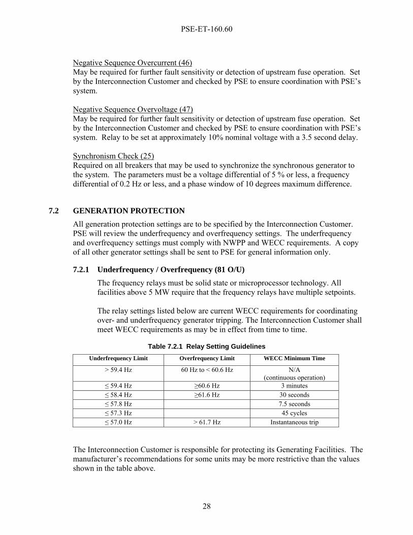
7.2.1 Underfrequency / Overfrequency (81 O/U) The frequency relays must be solid state or microprocessor technology. All facilities above 5 MW require that the frequency relays have multiple setpoints. The relay settings listed below are current WECC requirements for coordinating over- and underfrequency generator tripping. The Interconnection Customer shall meet WECC requirements as may be in effect from time to time.
Table 7.2.1 Relay Setting Guidelines
Underfrequency Limit Overfrequency Limit WECC Minimum Time
> 59.4 Hz 60 Hz to < 60.6 Hz N/A (continuous operation)
≤ 59.4 Hz ≥60.6 Hz 3 minutes ≤ 58.4 Hz ≥61.6 Hz 30 seconds ≤ 57.8 Hz 7.5 seconds ≤ 57.3 Hz 45 cycles ≤ 57.0 Hz > 61.7 Hz Instantaneous trip
The Interconnection Customer is responsible for protecting its Generating Facilities. The manufacturer’s recommendations for some units may be more restrictive than the values shown in the table above.

PSE-ET-160.60
29
7.2.2 Alternative to Meeting Underfrequency WECC Requirements The Interconnection Customer is responsible for protecting its electrical generating units. The manufacturer’s recommendations for some units may be more restrictive than the values shown in the Table 7.2.1 or then-current WECC requirements. Generating Facilities having generators that do not meet the above underfrequency requirements must automatically trip load or arrange with another system to automatically trip loads to match the anticipated generation loss at comparable frequency levels.


PSE-ET-160.60
31
8. DEMONSTRATION OF INTERCONNECTION CUSTOMER’S PROTECTIVE DEVICES
8.1 GENERAL The protective device demonstration shall be divided into two parts,
1. Calibration - The Calibration demonstration is to ensure that the agreed-upon settings are used on each of the relays required by PSE. This demonstration is also to ensure that the relays are functional and calibrated to manufacturer’s tolerances.
2. Trip and Circuit Checks - The Trip and Circuit Check demonstration is to ensure that each of the required relays is properly connected to the instrument transformers and operate the proper interrupting device. All of the initial tests must be successfully completed and certified test reports of relay and instrument transformers provided to PSE prior to interconnection with PSE’s system.
The following Calibration and Trip and Circuit Check sections are intended to serve as general requirements and are subject to negotiation. The actual demonstration will depend upon the final approved AC/DC schematics, relay settings, etc. It is the Interconnection Customer’s responsibility to demonstrate operation of all protective devices in a safe manner that does not adversely affect any equipment on the line.
8.2 CALIBRATION
8.2.1 Current Transformer (CT) Visually check polarity mark orientation on all CTs with respect to the AC schematics in the design drawings. Perform polarity checks of the CTs per the most current version of ANSI Standard C57. The following calibration tests shall also be performed:
• Verify the CT polarity.
• Verify that all grounding, shorting connections, and test blocks provided make good contact.
• CT single point grounding shall be confirmed for each CT circuit as shown on the drawings, with the preferred grounding location at or near the relay panel.
• Ratio CTs at specified tap ratio.
• Perform Megger® tests on all CTs to ground.

PSE-ET-160.60
32
• Perform demagnetization and excitation tests on CTs as the final tests on CTs.
• Check excitation test data against CT excitation curves.
8.2.2 Voltage Transformer (VT), Potential Device (PD), Capacitor Voltage Transformer (CVT), and Coupling-Capacitor Voltage Transformer (CCVT)
Visually check polarity mark orientation on all VTs, PDs, CVTs, and CCVTs with respect to the three-line diagrams in the design drawings and the manufacturer’s drawings. Test all polarities per the most current version of ANSI Standard C57.13.
• Verify polarity electrically relative to polarity marks.
• Verify ratio at specified tap.
• Verify VT, PD, CVT, and CCVT circuit single point grounding as shown on the drawings.
• Doble® power factor test all VTs, CVTs, and CCVTs.
• Adjust the PDs for the voltage and the burden of the secondary circuits to that they are being connected.
8.2.3 Relays Test relays with actual setting values to verify calibration, input mapping, and output mapping.
8.2.4 Testing and Calibration All testing and calibration of CTs, VTs, PDs, CVTs, CCVTs, and relays will be performed with test equipment of current calibration. “Current calibration” means:
• According to manufacturer’s calibration specifications and intervals;
• Within a one year interval of the last equipment calibration; and
• Proof of test equipment calibration must be provided to PSE prior to relay calibration.
8.3 TRIP AND CIRCUIT CHECKS All required relays shall be functionally operated to demonstrate proper interrupting device operation. Tests may be performed off-line, if possible. Tests that cannot be performed off-line must be demonstrated to operate on-line. Trip outputs from the relay may be arrived at either by manually operating all appropriate contacts, or by injecting an electrical signal to cause a trip output.

PSE-ET-160.60
33
Check continuity of the CT circuit to each relay by primary injection. Following energization, verify correct voltage polarity at relays (where applicable). Demonstrate that the interlocks between the generator and PSE’s breakers operate properly (e.g., Interconnection Customers cannot energize a dead line and can only tie to a hot line via a synchronizing device).


PSE-ET-160.60
35
9. DEMONSTRATION OF GENERATING SYSTEM FUNCTIONALITY
Interconnection Customers shall demonstrate to PSE the generator voltage controls and required reactive capabilities, the dispatch controls and monitoring equipment, the power system stabilizers, and the dynamic system response. PSE shall not be responsible for performing such demonstration(s). Interconnection Customers shall provide qualified personnel to perform the demonstrations. The Interconnection Customer must supply all personal protective equipment and designate any procedures necessary to ensure that safety precautions are taken while working near energized equipment. It is the responsibility of the Interconnection Customer to supply the actual written test procedures, that incorporate the following types of tests, to PSE for review prior to actual On-Line Start-Up Testing. The scheduling of this demonstration shall be coordinated with PSE, with a minimum of 7 days’ advance notice. The test procedures shall clearly show how generating system controls and parameters will be demonstrated, and they shall be provided to PSE for review and approval a minimum of 14 days before the demonstration. These requirements are intended to be non-destructive; however, PSE shall not be liable for any loss, damage or injury to equipment or persons (including death) resulting from the implementation of these requirements by the Interconnection Customer. It is the Interconnection Customer’s responsibility to test and demonstrate generating system in a safe manner that does not adversely affect the generator or other interconnected equipment.
9.1 ON-LINE START-UP TESTING The On-Line Start-Up Testing demonstration is to verify expected operation of synch check and interlocks specific to PSE/Interconnection Customer. The testing shall verify phase and rotation and the proper operation of the synchronizing relay. Voltage and current harmonics from the generator shall also be measured and must fall within the requirements of Section 3.1. For generation systems greater than 1 MW, a power quality analyzer (provided by the Interconnection Customer) shall be used to monitor all three-phase currents, three bus voltages, neutral current or generator neutral current, and an auxiliary contact from the Interconnection Customer’s generator breaker and also PSE’s line breaker(s). The analyzer will have a minimum sample rate of 167 microseconds (128 points per cycle). PSE requires that the analyzer monitor the pre breaker close conditions, the breaker closing, and the post close conditions of the system. Smaller generation sites may require this type of monitoring if the paralleling of the two systems produces a noticeable voltage dip or surge.
PSE-ET-160.60
36
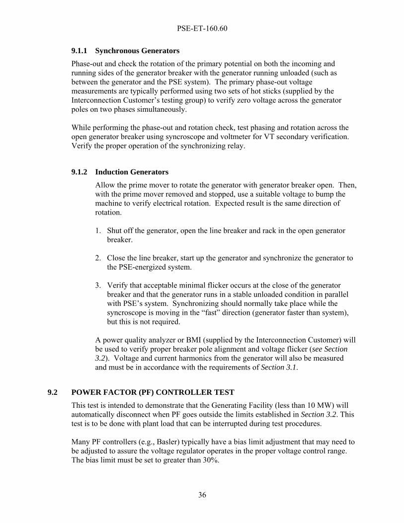
9.1.1 Synchronous Generators Phase-out and check the rotation of the primary potential on both the incoming and running sides of the generator breaker with the generator running unloaded (such as between the generator and the PSE system). The primary phase-out voltage measurements are typically performed using two sets of hot sticks (supplied by the Interconnection Customer’s testing group) to verify zero voltage across the generator poles on two phases simultaneously. While performing the phase-out and rotation check, test phasing and rotation across the open generator breaker using syncroscope and voltmeter for VT secondary verification. Verify the proper operation of the synchronizing relay.
9.1.2 Induction Generators Allow the prime mover to rotate the generator with generator breaker open. Then, with the prime mover removed and stopped, use a suitable voltage to bump the machine to verify electrical rotation. Expected result is the same direction of rotation.
1. Shut off the generator, open the line breaker and rack in the open generator
breaker.
2. Close the line breaker, start up the generator and synchronize the generator to the PSE-energized system.
3. Verify that acceptable minimal flicker occurs at the close of the generator
breaker and that the generator runs in a stable unloaded condition in parallel with PSE’s system. Synchronizing should normally take place while the syncroscope is moving in the “fast” direction (generator faster than system), but this is not required.
A power quality analyzer or BMI (supplied by the Interconnection Customer) will be used to verify proper breaker pole alignment and voltage flicker (see Section 3.2). Voltage and current harmonics from the generator will also be measured and must be in accordance with the requirements of Section 3.1.
9.2 POWER FACTOR (PF) CONTROLLER TEST This test is intended to demonstrate that the Generating Facility (less than 10 MW) will automatically disconnect when PF goes outside the limits established in Section 3.2. This test is to be done with plant load that can be interrupted during test procedures. Many PF controllers (e.g., Basler) typically have a bias limit adjustment that may need to be adjusted to assure the voltage regulator operates in the proper voltage control range. The bias limit must be set to greater than 30%.

PSE-ET-160.60
37
1. With the generator off-line, measure the power factor (PF) of the full house power kW load. The measured value will usually be lagging, not unity.
2. Set the generator PF controller to a more leading PF (usually unity). This creates a VAR mismatch between the load and generator. Also, temporarily block the 81 O/U relay.
3. Bring the generator on-line. The station service load should be served by the generator.
4. Match the generator kW to the house power load.
5. Trip the line breaker. 6. The generator should trip on low voltage due to PF mismatch by means of the
undervoltage relay. Note: A demonstration of compliance with contracted PF will be performed for induction generators and inverters.
9.3 VAR CAPACITY TESTS The Interconnection Customer is advised that for transmission or distribution-connected generators there may be significant VAR losses absorbed into the generator’s step-up transformer. These losses will impact the generating facility’s net VAR capability (and PF) when the metered point of interconnection is on the HV side of the transformer.
9.3.1 Distribution Connected Generators Generator installations 5 kW and higher must maintain a power factor between 0.98 bucking or leading and 0.95 boosting or lagging, inclusive, over an operating range of 25% (if possible), 50%, 75%, and 100% of rated generator MW or real power load at the Point of Interconnection. Generators below 5 kW must maintain 0.95 bucking or leading power factor at 100% rated generator MW or real power load at the Point of Interconnection. The capacity tests into the lead may be limited because of operational limitations due to manufacturer’s design criteria or stator end iron heating concerns. See Section 3.2 for power factor requirements.
9.3.2 Transmission Connected Generators
For synchronous generators, a demonstration of the Generating Facility’s lag and lead capability is required. Unless otherwise specified in the SGIA between PSE and the Producer, each generator must supply VAR’s as measured at the Point of Interconnection, in a range of operation between 95% bucking or leading to 95% boosting or lagging power factor. These tests must be conducted at 25% (if possible), 50%, 75%, and 100% of rated generator MW or real power load. The

PSE-ET-160.60
38
capacity tests into the lead may be limited because of operational limitations due to manufacturer’s design criteria or stator end iron heating concerns.
9.3.3 Transmission Connected Wind Power Generating Facilities Wind power Generating Facilities shall demonstrate the facility’s reactive power compensation scheme. Tests must be conducted beginning at 25% (if possible), 50%, 75%, and 100% of rated generator MW or real power load, that demonstrate that the switching and control of the reactive power can be done in small enough increments to limit the change in reactive power production or absorption in steady state of no more than 10% of the generated power. The wind power Generating Facility must regulate reactive power in a range of operation between a net 0.98 power factor bucking or leading and a net 0.95 power factor boosting or lagging at maximum generation output, at the Point of Interconnection.
9.4 AUTOMATIC GENERATION CONTROL DISPATCHABILITY TESTING When the MW output of the Interconnection Customer’s Generating Facility is required by PSE to be controlled with automatic generation control (AGC), the appropriate control and monitoring telemetry equipment must be installed and tested prior to commercial operation. These tests verify that the facility is able to continuously respond to PSE’s commands (pulses) at the required ramp rates (typically two percent of seasonal test capacity per minute), over the required regulating range of the facility (typically forty percent of seasonal test capacity). The telemetry meter indication (MW) is typically compared and verified with the revenue metering and local plant metering indications at this time. Often, the Generating Facility’s VAR capacity testing is performed at or about the same time as the AGC testing. The periodic testing (see Section 9.6) is normally performed later, after completion of all other On-Line Start-Up Testing, as the last test prior to commercial operation. For dispatchable generation, the Interconnection Customer may be required to demonstrate dispatch performance periodically.
9.5 POWER SYSTEM STABILIZER TESTS AND TUNING Power system stabilizers will be tested and tuned by a person that is qualified and trained in the operation of power system stabilizers. Power system stabilizer equipment shall be periodically tested and tuned in accordance with the WECC’s “Power System Stabilizers Tuning Guidelines” dated 2002 (or its successor requirement). Copies of this report are available from the WECC.
9.6 WECC-REQUIRED INITIAL AND PERIODIC TESTING All transmission-connected generators 10 MW and greater are required to perform testing on initial start-up of the Generating Facility and to perform periodic testing consistent with the requirements of the WECC Generating Unit Model Validation Policy, and the WECC Synchronous Unit Dynamic Testing & Model Validation prepared by the WECC Control Work Group and Modeling & Validation Work Group in February 1997 (or its

PSE-ET-160.60
39
successor requirement). This document is available on the WECC Web site at www.wecc.biz under Generator Testing. These tests are for:
• Verification of real and reactive power limits.
• Proper performance of the dynamic control systems.
• Computer simulation modeling data used for transient stability analysis, including excitation systems, voltage regulators, turbine-governor systems, power system stabilizers, and other associated generation equipment.

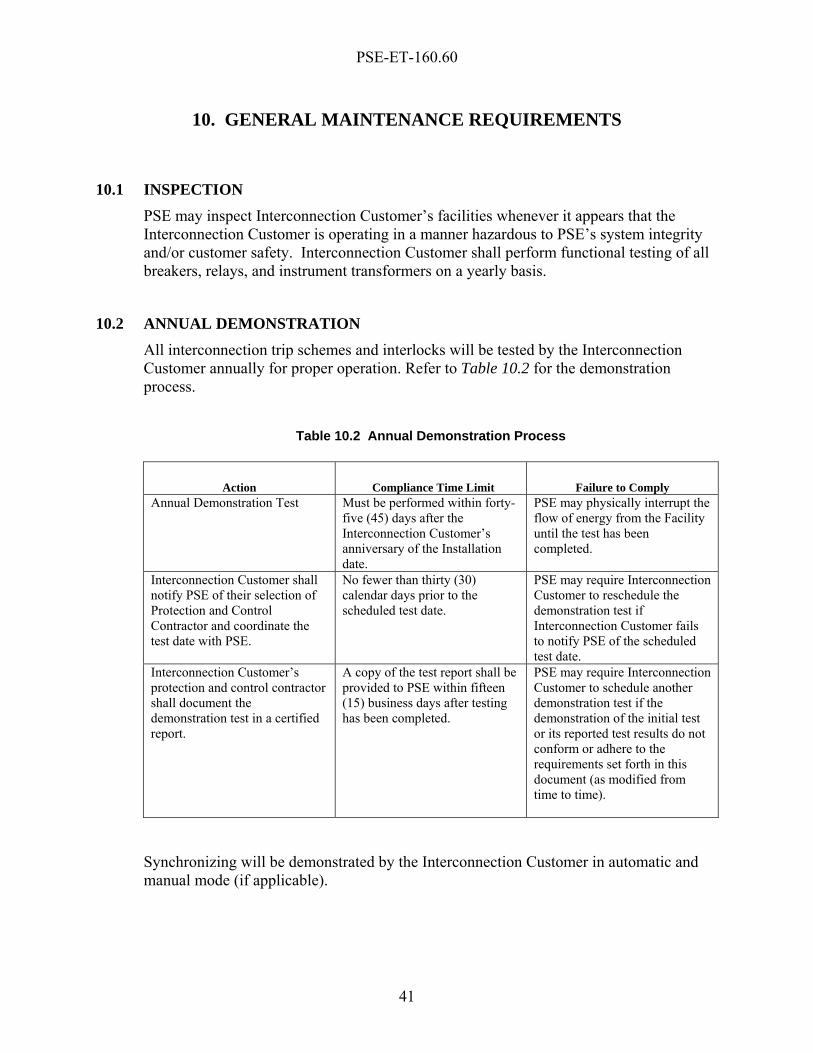
PSE-ET-160.60
41
10. GENERAL MAINTENANCE REQUIREMENTS
10.1 INSPECTION PSE may inspect Interconnection Customer’s facilities whenever it appears that the Interconnection Customer is operating in a manner hazardous to PSE’s system integrity and/or customer safety. Interconnection Customer shall perform functional testing of all breakers, relays, and instrument transformers on a yearly basis.
10.2 ANNUAL DEMONSTRATION All interconnection trip schemes and interlocks will be tested by the Interconnection Customer annually for proper operation. Refer to Table 10.2 for the demonstration process.
Table 10.2 Annual Demonstration Process
Action Compliance Time Limit Failure to Comply Annual Demonstration Test Must be performed within forty-
five (45) days after the Interconnection Customer’s anniversary of the Installation date.
PSE may physically interrupt the flow of energy from the Facility until the test has been completed.
Interconnection Customer shall notify PSE of their selection of Protection and Control Contractor and coordinate the test date with PSE.
No fewer than thirty (30) calendar days prior to the scheduled test date.
PSE may require Interconnection Customer to reschedule the demonstration test if Interconnection Customer fails to notify PSE of the scheduled test date.
Interconnection Customer’s protection and control contractor shall document the demonstration test in a certified report.
A copy of the test report shall be provided to PSE within fifteen (15) business days after testing has been completed.
PSE may require Interconnection Customer to schedule another demonstration test if the demonstration of the initial test or its reported test results do not conform or adhere to the requirements set forth in this document (as modified from time to time).
Synchronizing will be demonstrated by the Interconnection Customer in automatic and manual mode (if applicable).

PSE-ET-160.60
42
10.3 CALIBRATION DEMONSTRATION (EVERY 3 YEARS) In addition to all annual checks, the Interconnection Customer shall be required to demonstrate that the relays and meters are functional and calibrated to manufacturer’s tolerances and set to approved settings. Refer to manufacturer’s pamphlet for test procedures. Refer to Table 10.3 for the calibration demonstration process.
Table 10.3 Calibration Demonstration Process
Action Compliance Time Limit Failure to Comply Calibration Demonstration Every 3 Years
Must be performed within forty-five (45) days after the Interconnection Customer’s anniversary of the Installation date.
PSE may physically interrupt the flow of energy from the Facility until the test has been completed.
Interconnection Customer shall notify PSE of their selection of Protection and Control Contractor and coordinate the test date with PSE.
No fewer than thirty (30) calendar days prior to the scheduled test date.
PSE may require Interconnection Customer to reschedule the demonstration test if Interconnection Customer fails to notify PSE of the scheduled test date.
Interconnection Customer’s protection and control contractor shall document the demonstration test in a certified report.
A copy of the test report shall be provided to PSE within fifteen (15) business days after testing has been completed.
PSE may require Interconnection Customer to schedule another demonstration test if the demonstration of the initial test or its reported test results do not conform or adhere to the requirements set forth in this document (as modified from time to time).
For all transmission-connected Generating Facilities, VAR capacity tests and generating unit model validation will need to be performed and demonstrated in accordance with WECC and NERC requirements.
10.4 DESIGN CHANGES AFTER COMMERCIAL OPERATION Any modifications to the Generating Facility after the Commercial Operation Date must be submitted to PSE for review. Demonstration of Relay Calibration, Trip and Circuit Tests and On-Line Start-Up Testing may be required depending on the extent of the modification. Setting changes of any interconnection protection or synchronizing device must be approved by PSE with a hard copy of the changes forwarded to the designated PSE representative. Any “Field Modification” or “As-Built” AC/DC protection and synchronizing schematics associated with any interconnection device must be forwarded to the designated PSE representative. The final As-Built drawings shall be stamped by a Professional Engineer, registered in the State of Washington.
PSE-ET-160.60
43
11. OPERATING REQUIREMENTS
11.1 SWITCHING AND TAGGING RULES As contemplated by Section 12.1 of the SGIA, PSE will provide the Interconnection Customer with a copy of PSE’s Switching & Clearances Handbook, Standard Practice 0201.1011, Switching & Clearances Handbook, and the Interconnection Customer shall comply with applicable switching and tagging rules in obtaining or in providing clearances for work or for switching operations on equipment.
11.2 DE-ENERGIZED CIRCUITS A generation source shall not energize a de-energized PSE circuit under any circumstances unless under the direct orders of PSE’s Power Dispatcher/System Operator. Failure to observe this requirement will be cause for immediate disconnection of the Generating Facility.
11.3 OPERATING LOG The Interconnection Customer shall maintain an operating log at each Generating Facility 300 kW and over that parallels with the PSE system. The log shall indicate changes in operating status, trip operations, and other unusual conditions. The operating log shall be open to review by PSE in order to help resolve interconnected operating issues. The Generating Facility operator will cooperate with PSE in the analysis of disturbances to the facility’s generator or to PSE’s electric system by gathering and providing access to information relating to any disturbance, including information from oscillography, protective relay targets, breaker operations, and sequence of events records.
11.4 COMMUNICATIONS – FACILITIES 2 MW AND GREATER Generation sites of 2 MW and larger must provide the following:
• Voice communication to the Generating Facility via normal telephone lines or mutually agreed upon circuits.
• A 24-hour phone or pager number for the Generating Facility operator. The Generating Facility operator shall also have information for contacting PSE’s 24-hour Operations Center dispatchers.
• Demonstrated familiarity by the plant operating personnel with PSE line clearance/operating procedures (PSE Standard Practice 0201.1011 – Switching and Clearances Handbook) and applicable standard practices.
• Notification to PSE’s Dispatch Center prior to bringing any generating unit on-line in parallel with PSE’s system and the time of interconnection.
PSE-ET-160.60
44
• Generator sites that are dispatchable, 10 MW or greater, or are connected to the transmission system are required to notify PSE’s Dispatch Center concerning plans to switch on- or off-line.
• Immediately notification to PSE’s Dispatch Center of unplanned trip operations.
11.5 DISCONTINUANCE OF OPERATIONS Interconnection Customers shall discontinue parallel operation when requested by PSE, as follows:
• To facilitate maintenance, test, or repair of PSE facilities.
• To accommodate line clearances or non-recloses on associated circuit. PSE will notify the generator operator in advance of planned clearances or non-relcoses. During emergencies, PSE may not be able to give advance warning of being disconnected from the system.
• When the Interconnection Customer’s generating equipment is interfering with customers on the system due to degradation of power quality or service.
• When an inspection of the Interconnection Customer’s generating equipment reveals a condition hazardous to the PSE system or a lack of scheduled maintenance or maintenance records for equipment necessary to protect the PSE system.
• When Good Utility Practices warrant discontinued operation.
PSE-ET-160.60
45
ATTACHMENTS 1 through 6
INTERCONNECTION PROTECTION AND METERING DIAGRAMS
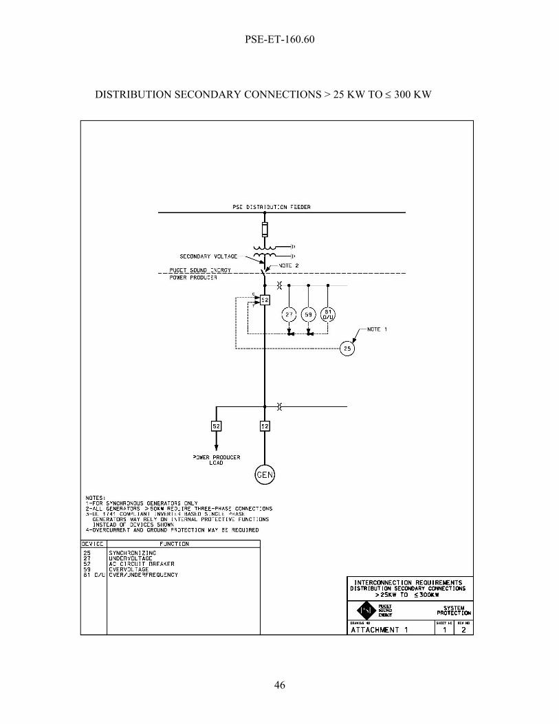
PSE-ET-160.60
46
DISTRIBUTION SECONDARY CONNECTIONS > 25 KW TO ≤ 300 KW
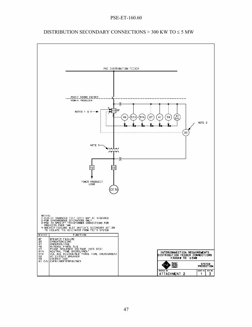
PSE-ET-160.60
47
DISTRIBUTION SECONDARY CONNECTIONS > 300 KW TO ≤ 5 MW
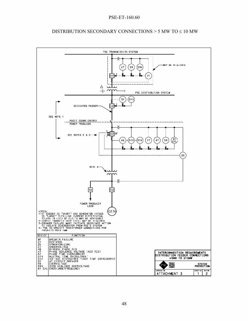
PSE-ET-160.60
48
DISTRIBUTION SECONDARY CONNECTIONS > 5 MW TO ≤ 10 MW

PSE-ET-160.60
49
TRANSMISSION CONNECTIONS

PSE-ET-160.60
50
METERING – OPTION “A”
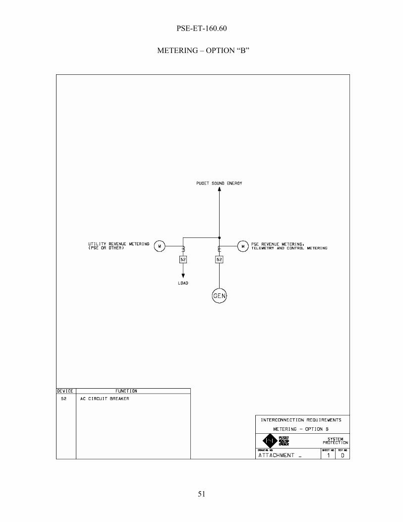
PSE-ET-160.60
51
METERING – OPTION “B”


PSE-ET-160.60
A-1
Appendix A
APPENDIX A
TECHNICAL SPECIFICATIONS AND OPERATING PROTOCOLS AND PROCEDURES FOR SMALL GENERATION INTERCONNECTIONS
SMALL GENERATING FACILITY DATA CONNECTED TO DISTRIBUTION SYSTEM, UNIT RATINGS
SYNCHRONOUS GENERATORS
GENERATOR UNIT RATINGS
Rating = _______ kVA @ _______ °F @ _______ kV @ _______ Power Factor
Speed = _______ RPM Connection (e.g. Wye) = ______________ Short Circuit Ratio = _______ Frequency = _______ Hertz Stator Amperes at Rated kVA = _______ amps Field Volts = _______ Volts Max Turbine = _______ kW @ _______ °F Turbine / Generator Pmax = _______ kW
Note: If requested information is not applicable, indicate by marking “N / A.”
COMBINED TURBINE-GENERATOR-EXCITER INERTIA DATA Inertia Constant, H = ______________ kW sec/kVA Moment-of-Inertia, WR2 = ______________ lb. ft.2 REACTANCE DATA (Per Unit Rated kVA)
DIRECT AXIS QUADRATURE AXIS Synchronous – saturated Xdv _______ Xqv _______ Synchronous – unsaturated Xdi _______ Xqi _______ Transient – saturated X’dv _______ X’qv _______ Transient – unsaturated X’di _______ X’qi _______ Subtransient – saturated X”dv _______ X”qv _______ Subtransient – unsaturated X”di _______ X”qi _______ Negative Sequence – saturated X2v _______ Negative Sequence – unsaturated X2i _______ Zero Sequence – saturated X0v _______ Zero Sequence – unsaturated X0i _______ Leakage Reactance Xlm _______

PSE-ET-160.60
A-2
Appendix A
FIELD TIME CONSTANT DATA (Seconds) Open Circuit T’do _______ T’qo _______ Three-Phase Short Circuit Transient T’d3 _______ T’q _______ Line to Line Short Circuit Transient T’d2 _______ Line to Neutral Short Circuit Transient T’d1 _______ Short Circuit Subtransient T”d _______ T”q _______ Open Circuit Subtransient T”do _______ T”qo _______ ARMATURE TIME CONSTANT DATA (Seconds) Three Phase Short Circuit Ta3 _______ Line to Line Short Circuit Ta2 _______ Line to Neutral Short Circuit Ta1 _______ EXCITATION SATURATION Saturation Factor at 1.0 per unit terminal voltage S(1.0) _______ Saturation Factor at 1.2 per unit terminal voltage S(1.2) _______ ARMATURE WINDING RESISTANCE DATA (Per Unit Rated kVA) Positive R1 _______ Negative R2 _______ Zero R0 _______ Rotor Short Time Thermal Capacity I2
2t = _______ Field Current at Rated kVA, Armature Voltage and PF = _______ amps Field Current at Rated kVA and Armature Voltage, 0 PF = _______ amps Three Phase Armature Winding Capacitance = _______ microfarad Field Winding Resistance = _______ ohms _____ °C Armature Winding Resistance (Per Phase) = _______ ohms _____ °C CURVES Provide: Saturation,
Vee, Reactive Capability, Capacity Temperature Correction curves. Designate normal and emergency
Hydrogen Pressure operating range for multiple curves. EXCITATION SYSTEM DATA Identify appropriate IEEE or PTI PSS/E model type and block diagram of the excitation system for computer representation in power system stability simulations, and the corresponding excitation system constants for use in the model.
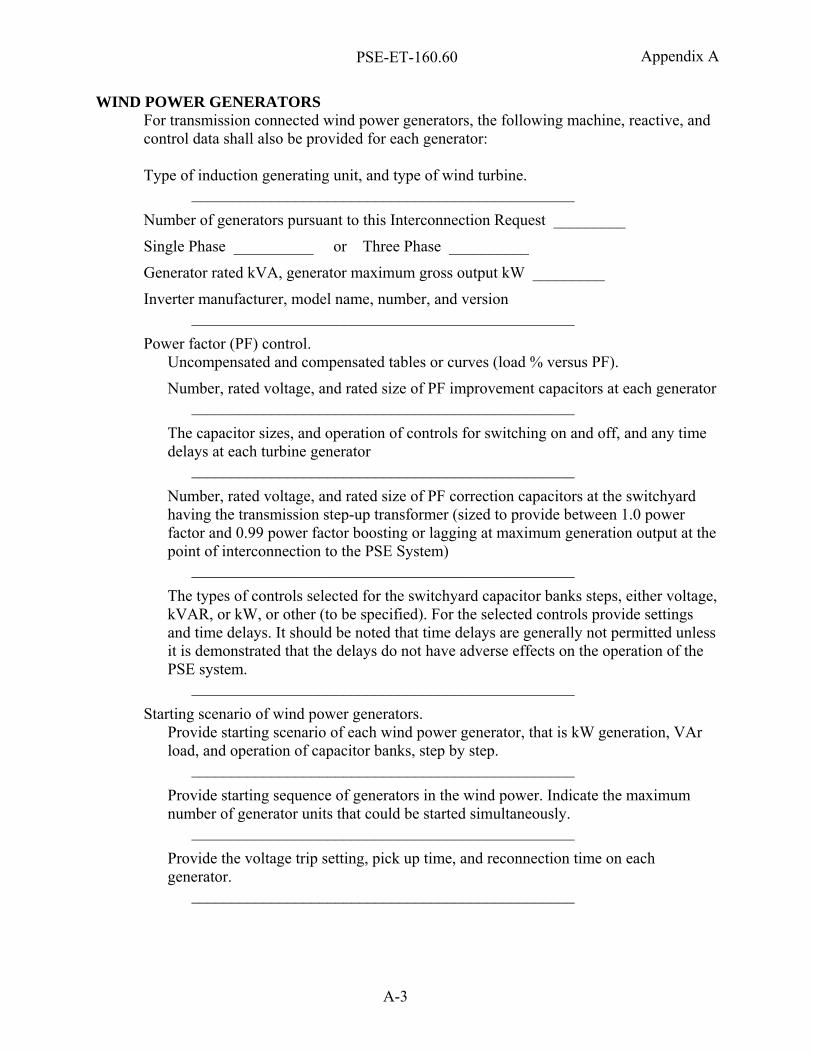
PSE-ET-160.60
A-3
Appendix A
WIND POWER GENERATORS For transmission connected wind power generators, the following machine, reactive, and control data shall also be provided for each generator: Type of induction generating unit, and type of wind turbine.
________________________________________________
Number of generators pursuant to this Interconnection Request _________
Single Phase __________ or Three Phase __________
Generator rated kVA, generator maximum gross output kW _________
Inverter manufacturer, model name, number, and version ________________________________________________
Power factor (PF) control. Uncompensated and compensated tables or curves (load % versus PF).
Number, rated voltage, and rated size of PF improvement capacitors at each generator ________________________________________________
The capacitor sizes, and operation of controls for switching on and off, and any time delays at each turbine generator
________________________________________________
Number, rated voltage, and rated size of PF correction capacitors at the switchyard having the transmission step-up transformer (sized to provide between 1.0 power factor and 0.99 power factor boosting or lagging at maximum generation output at the point of interconnection to the PSE System)
________________________________________________
The types of controls selected for the switchyard capacitor banks steps, either voltage, kVAR, or kW, or other (to be specified). For the selected controls provide settings and time delays. It should be noted that time delays are generally not permitted unless it is demonstrated that the delays do not have adverse effects on the operation of the PSE system.
________________________________________________
Starting scenario of wind power generators. Provide starting scenario of each wind power generator, that is kW generation, VAr load, and operation of capacitor banks, step by step.
________________________________________________
Provide starting sequence of generators in the wind power. Indicate the maximum number of generator units that could be started simultaneously.
________________________________________________
Provide the voltage trip setting, pick up time, and reconnection time on each generator.
________________________________________________
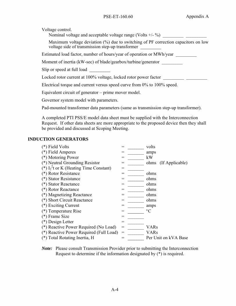
PSE-ET-160.60
A-4
Appendix A
Voltage control. Nominal voltage and acceptable voltage range (Volts +/- %) _________ _________ Maximum voltage deviation (%) due to switching of PF correction capacitors on low voltage side of transmission step-up transformer _________
Estimated load factor, number of hours/year of operation or MWh/year _________
Moment of inertia (kW-sec) of blade/gearbox/turbine/generator _________
Slip or speed at full load _________
Locked rotor current at 100% voltage, locked rotor power factor _________ _________
Electrical torque and current versus speed curve from 0% to 100% speed.
Equivalent circuit of generator – prime mover model.
Governor system model with parameters.
Pad-mounted transformer data parameters (same as transmission step-up transformer).
A completed PTI PSS/E model data sheet must be supplied with the Interconnection Request. If other data sheets are more appropriate to the proposed device then they shall be provided and discussed at Scoping Meeting.
INDUCTION GENERATORS
(*) Field Volts = _______ volts (*) Field Amperes = _______ amps (*) Motoring Power = _______ kW (*) Neutral Grounding Resistor = _______ ohms (If Applicable) (*) I2
2t or K (Heating Time Constant) = _______ (*) Rotor Resistance = _______ ohms (*) Stator Resistance = _______ ohms (*) Stator Reactance = _______ ohms (*) Rotor Reactance = _______ ohms (*) Magnetizing Reactance = _______ ohms (*) Short Circuit Reactance = _______ ohms (*) Exciting Current = _______ amps (*) Temperature Rise = _______ °C (*) Frame Size = _______ (*) Design Letter = _______ (*) Reactive Power Required (No Load) = _______ VARs (*) Reactive Power Required (Full Load) = _______ VARs (*) Total Rotating Inertia, H = _______ Per Unit on kVA Base Note: Please consult Transmission Provider prior to submitting the Interconnection
Request to determine if the information designated by (*) is required.
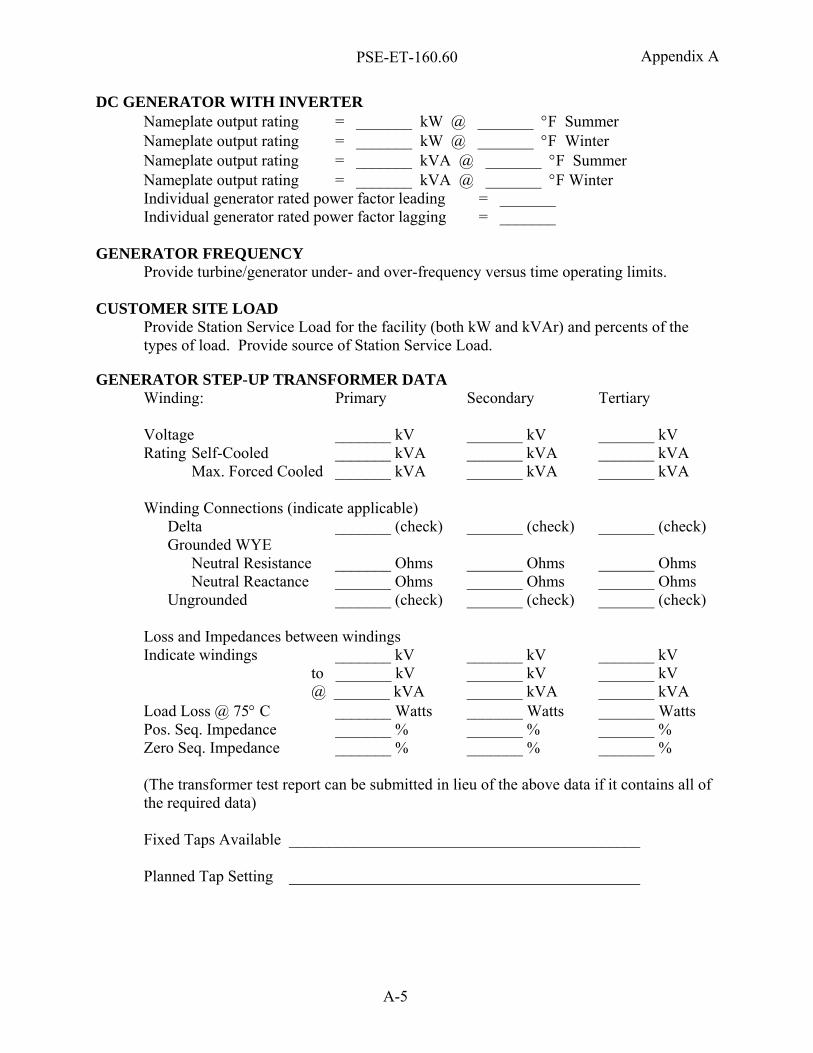
PSE-ET-160.60
A-5
Appendix A
DC GENERATOR WITH INVERTER Nameplate output rating = _______ kW @ _______ °F Summer Nameplate output rating = _______ kW @ _______ °F Winter Nameplate output rating = _______ kVA @ _______ °F Summer Nameplate output rating = _______ kVA @ _______ °F Winter Individual generator rated power factor leading = _______ Individual generator rated power factor lagging = _______
GENERATOR FREQUENCY
Provide turbine/generator under- and over-frequency versus time operating limits.
CUSTOMER SITE LOAD Provide Station Service Load for the facility (both kW and kVAr) and percents of the types of load. Provide source of Station Service Load.
GENERATOR STEP-UP TRANSFORMER DATA Winding: Primary Secondary Tertiary Voltage _______ kV _______ kV _______ kV Rating Self-Cooled _______ kVA _______ kVA _______ kVA Max. Forced Cooled _______ kVA _______ kVA _______ kVA Winding Connections (indicate applicable) Delta _______ (check) _______ (check) _______ (check) Grounded WYE Neutral Resistance _______ Ohms _______ Ohms _______ Ohms Neutral Reactance _______ Ohms _______ Ohms _______ Ohms Ungrounded _______ (check) _______ (check) _______ (check) Loss and Impedances between windings Indicate windings _______ kV _______ kV _______ kV to _______ kV _______ kV _______ kV @ _______ kVA _______ kVA _______ kVA Load Loss @ 75° C _______ Watts _______ Watts _______ Watts Pos. Seq. Impedance _______ % _______ % _______ % Zero Seq. Impedance _______ % _______ % _______ % (The transformer test report can be submitted in lieu of the above data if it contains all of the required data) Fixed Taps Available ____________________________________________ Planned Tap Setting ____________________________________________

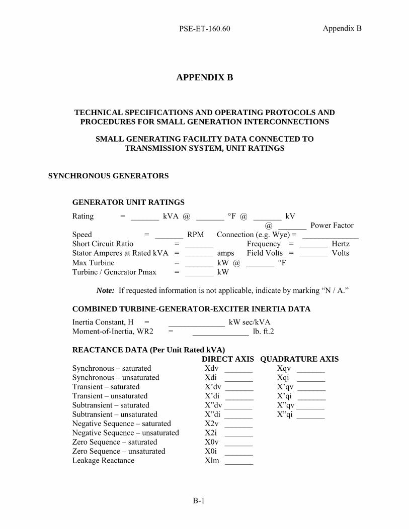
PSE-ET-160.60
B-1
Appendix B
APPENDIX B
TECHNICAL SPECIFICATIONS AND OPERATING PROTOCOLS AND PROCEDURES FOR SMALL GENERATION INTERCONNECTIONS
SMALL GENERATING FACILITY DATA CONNECTED TO TRANSMISSION SYSTEM, UNIT RATINGS
SYNCHRONOUS GENERATORS
GENERATOR UNIT RATINGS
Rating = _______ kVA @ _______ °F @ _______ kV @ _______ Power Factor
Speed = _______ RPM Connection (e.g. Wye) = ______________ Short Circuit Ratio = _______ Frequency = _______ Hertz Stator Amperes at Rated kVA = _______ amps Field Volts = _______ Volts Max Turbine = _______ kW @ _______ °F Turbine / Generator Pmax = _______ kW
Note: If requested information is not applicable, indicate by marking “N / A.” COMBINED TURBINE-GENERATOR-EXCITER INERTIA DATA Inertia Constant, H = ______________ kW sec/kVA Moment-of-Inertia, WR2 = ______________ lb. ft.2 REACTANCE DATA (Per Unit Rated kVA)
DIRECT AXIS QUADRATURE AXIS Synchronous – saturated Xdv _______ Xqv _______ Synchronous – unsaturated Xdi _______ Xqi _______ Transient – saturated X’dv _______ X’qv _______ Transient – unsaturated X’di _______ X’qi _______ Subtransient – saturated X”dv _______ X”qv _______ Subtransient – unsaturated X”di _______ X”qi _______ Negative Sequence – saturated X2v _______ Negative Sequence – unsaturated X2i _______ Zero Sequence – saturated X0v _______ Zero Sequence – unsaturated X0i _______ Leakage Reactance Xlm _______
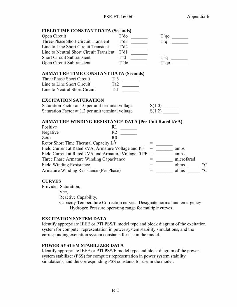
PSE-ET-160.60
B-2
Appendix B
FIELD TIME CONSTANT DATA (Seconds) Open Circuit T’do _______ T’qo _______ Three-Phase Short Circuit Transient T’d3 _______ T’q _______ Line to Line Short Circuit Transient T’d2 _______ Line to Neutral Short Circuit Transient T’d1 _______ Short Circuit Subtransient T”d _______ T”q _______ Open Circuit Subtransient T”do _______ T”qo _______
ARMATURE TIME CONSTANT DATA (Seconds) Three Phase Short Circuit Ta3 _______ Line to Line Short Circuit Ta2 _______ Line to Neutral Short Circuit Ta1 _______ EXCITATION SATURATION Saturation Factor at 1.0 per unit terminal voltage S(1.0) _______ Saturation Factor at 1.2 per unit terminal voltage S(1.2) _______ ARMATURE WINDING RESISTANCE DATA (Per Unit Rated kVA) Positive R1 _______ Negative R2 _______ Zero R0 _______ Rotor Short Time Thermal Capacity I2
2t = _______ Field Current at Rated kVA, Armature Voltage and PF = _______ amps Field Current at Rated kVA and Armature Voltage, 0 PF = _______ amps Three Phase Armature Winding Capacitance = _______ microfarad Field Winding Resistance = _______ ohms _____ °C Armature Winding Resistance (Per Phase) = _______ ohms _____ °C CURVES Provide: Saturation,
Vee, Reactive Capability, Capacity Temperature Correction curves. Designate normal and emergency
Hydrogen Pressure operating range for multiple curves. EXCITATION SYSTEM DATA Identify appropriate IEEE or PTI PSS/E model type and block diagram of the excitation system for computer representation in power system stability simulations, and the corresponding excitation system constants for use in the model. POWER SYSTEM STABILIZER DATA Identify appropriate IEEE or PTI PSS/E model type and block diagram of the power system stabilizer (PSS) for computer representation in power system stability simulations, and the corresponding PSS constants for use in the model.
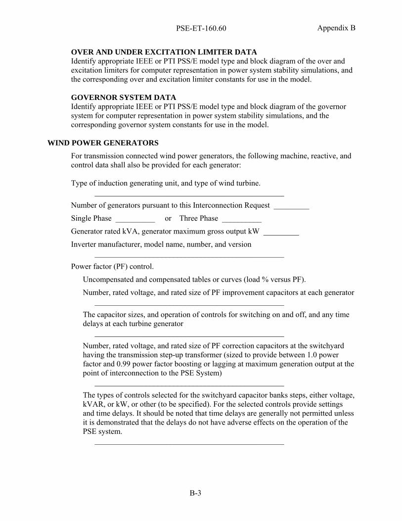
PSE-ET-160.60
B-3
Appendix B
OVER AND UNDER EXCITATION LIMITER DATA Identify appropriate IEEE or PTI PSS/E model type and block diagram of the over and excitation limiters for computer representation in power system stability simulations, and the corresponding over and excitation limiter constants for use in the model. GOVERNOR SYSTEM DATA Identify appropriate IEEE or PTI PSS/E model type and block diagram of the governor system for computer representation in power system stability simulations, and the corresponding governor system constants for use in the model.
WIND POWER GENERATORS
For transmission connected wind power generators, the following machine, reactive, and control data shall also be provided for each generator: Type of induction generating unit, and type of wind turbine.
________________________________________________
Number of generators pursuant to this Interconnection Request _________
Single Phase __________ or Three Phase __________
Generator rated kVA, generator maximum gross output kW _________
Inverter manufacturer, model name, number, and version ________________________________________________
Power factor (PF) control.
Uncompensated and compensated tables or curves (load % versus PF).
Number, rated voltage, and rated size of PF improvement capacitors at each generator ________________________________________________
The capacitor sizes, and operation of controls for switching on and off, and any time delays at each turbine generator
________________________________________________
Number, rated voltage, and rated size of PF correction capacitors at the switchyard having the transmission step-up transformer (sized to provide between 1.0 power factor and 0.99 power factor boosting or lagging at maximum generation output at the point of interconnection to the PSE System)
________________________________________________
The types of controls selected for the switchyard capacitor banks steps, either voltage, kVAR, or kW, or other (to be specified). For the selected controls provide settings and time delays. It should be noted that time delays are generally not permitted unless it is demonstrated that the delays do not have adverse effects on the operation of the PSE system.
________________________________________________
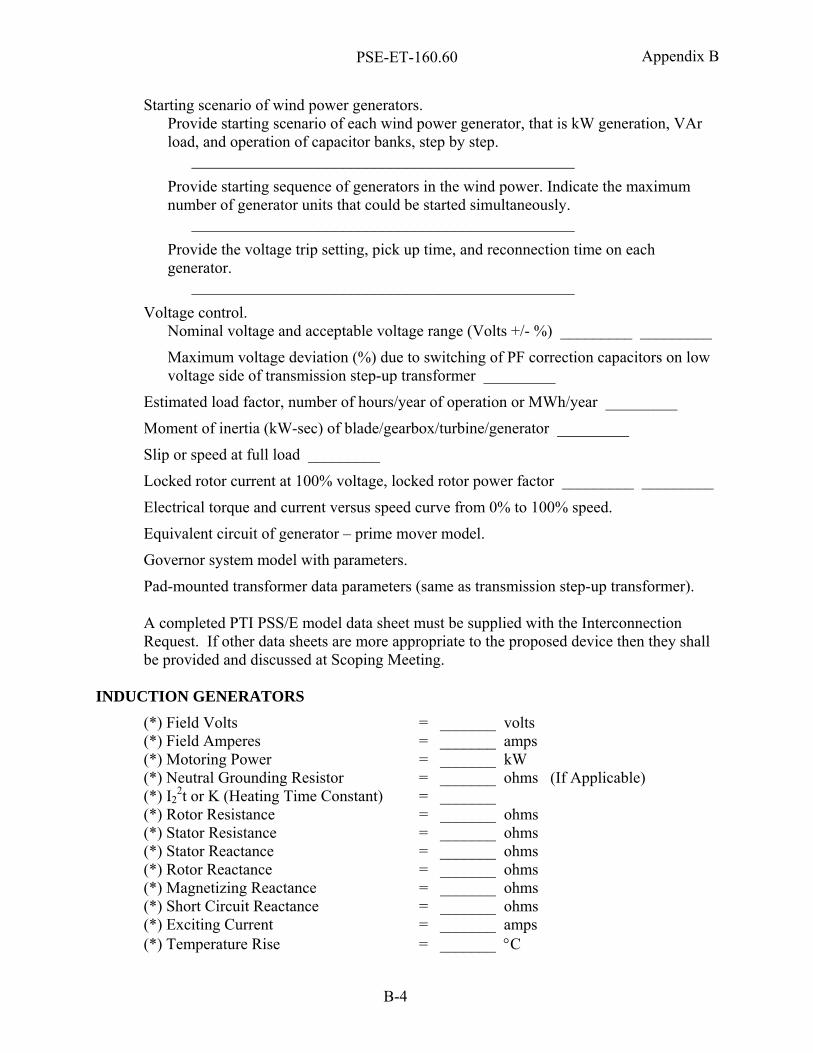
PSE-ET-160.60
B-4
Appendix B
Starting scenario of wind power generators. Provide starting scenario of each wind power generator, that is kW generation, VAr load, and operation of capacitor banks, step by step.
________________________________________________
Provide starting sequence of generators in the wind power. Indicate the maximum number of generator units that could be started simultaneously.
________________________________________________
Provide the voltage trip setting, pick up time, and reconnection time on each generator.
________________________________________________
Voltage control. Nominal voltage and acceptable voltage range (Volts +/- %) _________ _________
Maximum voltage deviation (%) due to switching of PF correction capacitors on low voltage side of transmission step-up transformer _________
Estimated load factor, number of hours/year of operation or MWh/year _________
Moment of inertia (kW-sec) of blade/gearbox/turbine/generator _________
Slip or speed at full load _________
Locked rotor current at 100% voltage, locked rotor power factor _________ _________
Electrical torque and current versus speed curve from 0% to 100% speed.
Equivalent circuit of generator – prime mover model.
Governor system model with parameters.
Pad-mounted transformer data parameters (same as transmission step-up transformer). A completed PTI PSS/E model data sheet must be supplied with the Interconnection Request. If other data sheets are more appropriate to the proposed device then they shall be provided and discussed at Scoping Meeting.
INDUCTION GENERATORS
(*) Field Volts = _______ volts (*) Field Amperes = _______ amps (*) Motoring Power = _______ kW (*) Neutral Grounding Resistor = _______ ohms (If Applicable) (*) I2
2t or K (Heating Time Constant) = _______ (*) Rotor Resistance = _______ ohms (*) Stator Resistance = _______ ohms (*) Stator Reactance = _______ ohms (*) Rotor Reactance = _______ ohms (*) Magnetizing Reactance = _______ ohms (*) Short Circuit Reactance = _______ ohms (*) Exciting Current = _______ amps (*) Temperature Rise = _______ °C
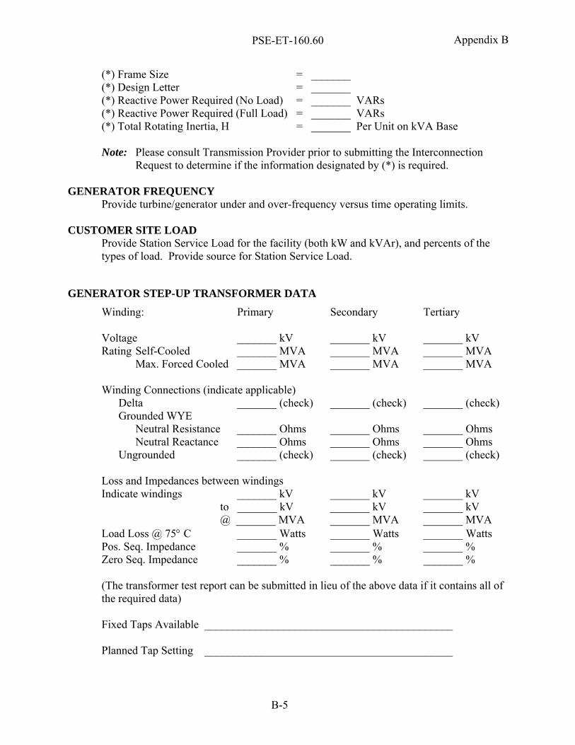
PSE-ET-160.60
B-5
Appendix B
(*) Frame Size = _______ (*) Design Letter = _______ (*) Reactive Power Required (No Load) = _______ VARs (*) Reactive Power Required (Full Load) = _______ VARs (*) Total Rotating Inertia, H = _______ Per Unit on kVA Base Note: Please consult Transmission Provider prior to submitting the Interconnection
Request to determine if the information designated by (*) is required.
GENERATOR FREQUENCY Provide turbine/generator under and over-frequency versus time operating limits.
CUSTOMER SITE LOAD Provide Station Service Load for the facility (both kW and kVAr), and percents of the types of load. Provide source for Station Service Load.
GENERATOR STEP-UP TRANSFORMER DATA Winding: Primary Secondary Tertiary Voltage _______ kV _______ kV _______ kV Rating Self-Cooled _______ MVA _______ MVA _______ MVA Max. Forced Cooled _______ MVA _______ MVA _______ MVA Winding Connections (indicate applicable) Delta _______ (check) _______ (check) _______ (check) Grounded WYE Neutral Resistance _______ Ohms _______ Ohms _______ Ohms Neutral Reactance _______ Ohms _______ Ohms _______ Ohms Ungrounded _______ (check) _______ (check) _______ (check) Loss and Impedances between windings Indicate windings _______ kV _______ kV _______ kV to _______ kV _______ kV _______ kV @ _______ MVA _______ MVA _______ MVA Load Loss @ 75° C _______ Watts _______ Watts _______ Watts Pos. Seq. Impedance _______ % _______ % _______ % Zero Seq. Impedance _______ % _______ % _______ % (The transformer test report can be submitted in lieu of the above data if it contains all of the required data) Fixed Taps Available ____________________________________________ Planned Tap Setting ____________________________________________