technical specifications a - spal-usa. · pdf filewith alarm armed or disarmed, press button...
TRANSCRIPT

A
BGENERAL FEATURES
- Installation possible on all vehicles with 12 V battery with earthed negative.- To be fitted inside vehicle.- Carefully read the following instructions and technical specifications.- Before fitting the appliance, it is best to become acquainted with the precautions to be taken. These are shown in the ÒOperatorÕs and MaintenanceÓ booklet.- This product is made taking into account the technical requirements of the European Directive on Alarm Systems 95/54/CE.
mod
.601
2.10
73/U
K -
02/
2004
Power Supply ................................. 12 V (10 V min 16 V max)
Max unit current absorption (@ 12V) ............................. 11 mA
Operating temperature ..................................... - 40� C + 85� C
Initial neutral time ........................................................... 40 sec.
Duration of alarm ............................................................ 30 sec.
Alarm recycle time ............................................................ 5 sec.
Direction indicator relay capacity ................................. 7 + 7 A
Power locking system relay capacity ............................... 15 A
Negative output max. capacity(AUX1 Ð Engine Cut Ð Dome Light).............................. 300 mA
Optional accessories:
- Back-up battery siren SIR 2 Code 3560.0104
- Back-up battery siren SIR 5 Code 3560.0106
- Siren without back-up battery SIR 4 Code 3560.0103
- Ultrasonic module MUS 3 Code 3560.0034
- Hyperfrequency module Code 3560.0014
- Dual zone Hyperfrequency module Code 3560.0012
- Dual zone Shock Sensor Module MSS 2 Code 3560.0020
- Anti-carlift module MTS 1 Code 3560.0017
- Universal power windows module MAV 6 Code 3560.0003
- Power windows module MAV 8 Code 3560.0011
- Relay 12 V - 30 A (N.O.) Code 3304.0071
- Relay 12 V - 15/30 A (N.C./N.O.) Code 3304.0079
- Wires for connecting 2 external modules Code 6000.5048
- Extended Range Antenna Code 3560.0010
TECHNICAL SPECIFICATIONS
Back-up battery siren SIR 5 with integrated hood pin-switch cable.Code 3560.0106
Ultrasonic module MUS 3 Code 3560.0034
ANTENNA
18 -pin connector
WHITE connector for LED
P3
P1 P2
LOW BATTERY INDICATORIf the battery of the remote control unit is low, this is indicated bythe flashing of the LED on the unit itself, when a key is pressed,and by 6 fast flashes of the direction indicators at arming.
TABLE OF CONTENTS
TECHNICAL SPECIFICATIONS..............................A
GENERAL FEATURES............................................B
WIRING DIAGRAM ..................................................C
POWER LOCKING SYSTEM CONNECTION .........D
ENGINE CUT CONNECTION .................................. E
DOME LIGHT CONNECTION ................................. F
AUXILIARY OUTPUTS ........................................... G
CONTROL UNIT OPERATION ................................H
VALET MODE ........................................................... I
EMERGENCY SYSTEM DISARMING..................... J
PROGRAMMING A NEW REMOTE CONTROL .....K
PROGRAMMABLE FUNCTIONS............................ L
This product must be fitted by a professional installer.THE INSTALLATION CERTIFICATE (supplied togetherwith the WARRANTY CERTIFICATE, to be completedand returned) must be completed by the installer. Anyamendments or additions not shown in this manualshall automatically invalidate the INSTALLATIONCERTIFICATE.
This appliance must only be powered by batteries orsafety stabilized supply units featuring 12V DC short-circuit cutouts.Do not connect any terminal to parts with hazardousvoltage.
CAUTION! This appliance is made only for very lowsafety voltages. Connections to circuits withhazardous voltages could be dangerous.
Carry out the installation AFTER disconnecting thevehicle battery.
WHITE connector for SPAL modules
BLACK connector for SPAL siren
FCC ID: KNF - TX3G2
AS 80Cod.3450.0083
e1 A - 00 0265
��
KIT AS 80 - 81 - 82 - 83 - 84 - 85 - 86REMOTE-CONTROLLED ALARM UNIT
Frequency 433.92 Mhz - Random Code - European Standards

+12V+30 permanent positive
protected by fuse(ex. dome light)
VIOLET
ORANGE
PINK
RED
ENGINE CUTNegative output
Max 300 mA
WHITEBLACK SIREN negative
output AUXMax 1 A
WHITE/BLACK
BROWN
Negative outputAUX
Max 300 mA
GREY/BLACK
negative output of domelight switch-on at disarming
GREY/BLACK
GREY
YELLOW
YELLOW
BLACK
Power lockingsystem connections
RED
Hood/trunkpin switch input
Page 3/Step 5ON
Page 3/Step 5OFF
Doorhood
trunk pin-switches
Directionindicators
12V Battery
FUSE 15A
BLUE
BLUE/RED
BLUE/BLACK
GREEN
GREEN/RED
GREEN/BLACK
ALTERNATIVE CONNECTIONSTO BE SELECTED BY PROGRAMMING
15positive presentalso at ignition
EXTERNAL MODULEnegative output
Max 10 mA
F
WIRING DIAGRAM
DOME LIGHT SWITCH-ON
ATo switch the vehicle dome-light on at door unlocking by means of the remotecontrol, connect as follows.
Note: Do not connect the GREY/BLACK wire to dome light: use an additionalrelay code 3304.0079.
ENABLE FUNCTION Pag. 3 / Step 5 in user programming(box L, Page 3 / Step 5 = ON)
If this function is not used, the GREY/BLACK wire is a negative perimeteralarm input.Box M: programmable function Page 3/Step 5 = OFF
25Ó�
WIRING DIAGRAMS
SPAL relay,Code 3304.0071
EENGINE CUT CONNECTION
WARNING: Do not interrupt ignition systems on petrol-drivenvehicles with Catalytic exhaust!
A double engine cut can be achieved by connecting the two relays shown in parallel!(max. current absorption 300 mA)
To achieve engine cut, connect an additional relay to the PINK wire.Interrupt the starting motor control (+50) or the fuel pump.
1) SPAL relay with normally-closed contact Code 3304.0079. Make one of theconnections shown below. The programmable function (Box L) on Page 2/Step 5must be OFF (standard programming).
2) SPAL relay with normally-closed contact Code 3304.0071. Make one of theconnections shown below using terminal 87 in place of 87A. The programmablefunction (Box L) on Page 2/Step 5 must be ON.
DIAGRAM FOR HORN CONNECTION
For negative output wiring:- ENGINE CUT- AUX OUTPUT- DOME LIGHT AT DISARMINGalways use an additional relay.
SPAL relaycode 3304.0079
YELLOW
WHITE
ORANGE (+15)
PINK
PETROLPUMP RELAY
DIESEL PUMPSOLENOID VALVE
STARTINGMOTOR
ORANGE (+15)
PINK
DOORPIN-SWITCHES
DOME LIGHT
GREY/BLACK(-)
DOORPIN-SWITCHES
DOME LIGHT
GREY/BLACK(-)
C
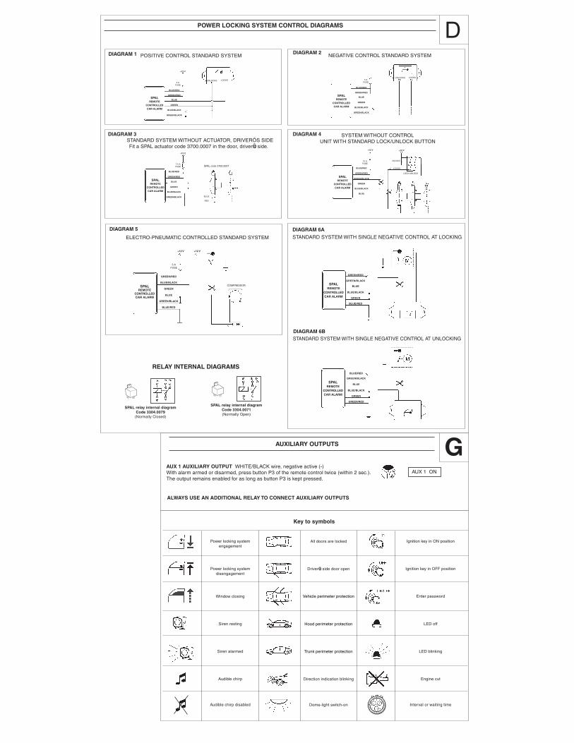
POWER LOCKING SYSTEM CONTROL DIAGRAMS
RELAY INTERNAL DIAGRAMS
GAUXILIARY OUTPUTS
AUX 1 AUXILIARY OUTPUT WHITE/BLACK wire, negative active (-)With alarm armed or disarmed, press button P3 of the remote control twice (within 2 sec.).The output remains enabled for as long as button P3 is kept pressed.
DIAGRAM 1
DIAGRAM 3 DIAGRAM 4
DIAGRAM 2
DIAGRAM 6A
ALWAYS USE AN ADDITIONAL RELAY TO CONNECT AUXILIARY OUTPUTS
POSITIVE CONTROL STANDARD SYSTEM NEGATIVE CONTROL STANDARD SYSTEM
STANDARD SYSTEM WITHOUT ACTUATOR, DRIVERÕS SIDEFit a SPAL actuator code 3700.0007 in the door, driverÕs side.
SYSTEM WITHOUT CONTROLUNIT WITH STANDARD LOCK/UNLOCK BUTTON
STANDARD SYSTEM WITH SINGLE NEGATIVE CONTROL AT LOCKING
DIAGRAM 6BSTANDARD SYSTEM WITH SINGLE NEGATIVE CONTROL AT UNLOCKING
� AUX 1 ON
DIAGRAM 5
ELECTRO-PNEUMATIC CONTROLLED STANDARD SYSTEM
SPAL relay internal diagramCode 3304.0079
(Normally Closed)
SPAL relay internal diagramCode 3304.0071(Normally Open)
��
SPALREMOTE
CONTROLLEDCAR ALARM
5 AFUSE
BLUE/RED
GREEN/RED
BLUE
GREEN
BLUE/BLACK
GREEN/BLACK
+12 V
UNLOCKS LOCKSUNLOCKS LOCKS
SPALREMOTE
CONTROLLEDCAR ALARM
5 AFUSE
BLUE/RED
GREEN/RED
BLUE
GREEN
BLUE/BLACK
GREEN/BLACK
SPALREMOTE
CONTROLLEDCAR ALARM
7.5 AFUSE
BLUE/RED
GREEN/RED
BLUE
GREEN
BLUE/BLACK
GREEN/BLACK
+12 V
SPAL code 3700.0007
BLUE
RED
SPALREMOTE
CONTROLLEDCAR ALARM
BLUE/RED
GREEN/RED
GREEN/BLACK
GREEN
BLUE/BLACK
BLUE
15 AFUSE
+12 V +12 V
UNLOCKS
LOCKS
LOCK-UNLOCK
SPALREMOTE
CONTROLLEDCAR ALARM
5 AFUSE
GREEN/RED
BLUE/BLACK
GREEN
BLUE
GREEN/BLACK
BLUE/RED
+12 V +12 V
COMPRESSOR SPALREMOTE
CONTROLLEDCAR ALARM
GREEN/RED
GREEN/BLACK
BLUE
BLUE/BLACK
GREEN
BLUE/RED
SPALREMOTE
CONTROLLEDCAR ALARM
BLUE/RED
GREEN/BLACK
BLUE
BLUE/BLACK
GREEN
GREEN/RED
All doors are locked
Vehicle perimeter protection
Hood perimeter protection
Trunk perimeter protection
Direction indication blinking
Dome-light switch-on
DriverÕs side door open
Key to symbols
Ignition key in ON position
Enter password
LED off
LED blinking
Engine cut
Interval or waiting time
Ignition key in OFF position
Power locking systemengagement
Window closing
Siren resting
Siren alarmed
Audible chirp
Audible chirp disabled
Power locking systemdisengagement
D