technical specification - ece llpecellp.com/wp-content/uploads/2017/03/rig-2-zj70.pdf · 3.1 mud...
TRANSCRIPT

Technical Specification SD Rig 02 ZJ70LC
2000 HP

Page 1 of 46
INDEX
1 The Drilling Unit .................................................................................................................................... 3 1.1 Drilling Unit Details .................................................................................................................... 3 1.2 Drawworks Details .......................................................................................................................... 3 1.3 Mast Specifications ................................................................................................................... 4 1.4 Sub-Structure ......................................................................................................................................... 4 1.5 Travelling Assembly .................................................................................................................. 5 1.6 Top Drive, ........................................................................................................................................ 5 1.7 Drill Line .................................................................................................................................... 5 2 Rotary Equipment ........................................................................................................................... 6
2.1 Rotary Table ............................................................................................................................. 6 3 Pumping and High Pressure Discharge System ........................................................................... 6
3.1 Mud Pumps ............................................................................................................................... 6 3.2 High Pressure Mud Lines .......................................................................................................... 7 4 Low Pressure Mud System .................................................................................................................. 7 4.1 Mud Mixing extra mixing pump .............................................................................................. 7 4.2 Shale Shakers ........................................................................................................................... 8 4.3 Desander ................................................................................................................................................ 8 4.4 Desilter .................................................................................................................................................... 9 4.5 Mud Cleaner / Centrifuge .......................................................................................................... 9 4.6 Mud Tanks ................................................................................................................................ 9 4.7 Trip Tank ................................................................................................................................. 10
4.8 Water Tanks ........................................................................................................................... 10 4.9 Cellar Pumps .......................................................................................................................... 10 4.10 Mud Agitators .......................................................................................................................... 10 4.11 Casing Fill-up Line .................................................................................................................. 10 4.12 Well Fill-up Line....................................................................................................................... 11 4.13 Other Mud Equipment ............................................................................................................. 11 5 Power Plant ................................................................................................................................... 11
5.1 Engine - AC Generator Sets.................................................................................................... 11 5.2 SCR's (optional) ............................................................................................................................ 11 5.3 Diesel Engines ........................................................................................................................ 12 5.4 Lines, Switchboards ................................................................................................................ 12 5.5 Third Party Power Availability .................................................................................................. 12 5.6 Fuel Tanks .............................................................................................................................. 12 5.7 Emergency Generators ................................................................................................................ 12 6 Blowout Prevention and Well Control Equipment ...................................................................... 13 6.1 13 5/8 in BOP Stack ..................................................................................................................... 13 6.2 Drilling Spools and Adapters .................................................................................................. 14 6.3 Accumulator Unit ..................................................................................................................... 14 6.4 BOP Control System ............................................................................................................... 15 6.5 Choke Manifold ............................................................................................................................. 15 6.6 Choke Lines ............................................................................................................................ 16 6.7 Kill Lines.................................................................................................................................. 16 6.8 BOP Testing and Handling Equipment .................................................................................... 16 6.9 String Safety Valves (Non-Return) .......................................................................................... 17 6.10 Upper Kelly Cock .................................................................................................................... 17 6.11 Lower Kelly Cock .................................................................................................................... 18 6.12 Float Valves .................................................................................................................................. 18 6.13 Bell Nipples ............................................................................................................................. 18 6.14 Vent Lines from Degasser ............................................................................................................ 18 6.15 Mud Gas Separator (Poorboy- Gas buster etc) ....................................................................... 18 6.16 Vacuum Degasser ........................................................................................................................ 19 6.17 Kelly and Kelly Spinner ................................................................................................................. 19 7 Rig Floor Equipment ..................................................................................................................... 19
7.1 Elevators .............................................................................................................................................. 19 7.1.1 Centre Latch/Side Door Drill Pipe & Drill Collar ................................................................................... 19 7.1.2 Casing Side Door Elevators ................................................................................................................ 20 7.1.3 Casing Spiders/Slips ................................................................................................................................. 21 7.1.4 Casing Single Joint Elevators .............................................................................................................. 21

Page 2 of 46
7.1.5 Elevator Links...................................................................................................................................... 21 7.2 Slip Requirements ................................................................................................................... 22
7.2.1 Manual Slips ........................................................................................................................................ 22 7.2.2 Casing & tubing Slips and Casing Bowls for Master Bushings ............................................................... 22
7.2.3 Safety Clamps ..................................................................................................................................... 22 7.3 Tongs and Casing Equipment ................................................................................................. 23
7.3.1 Rotary Tongs with Torque Indicator..................................................................................................... 23 7.3.2 Manual Casing Tongs ......................................................................................................................... 23 7.3.3 Power Casing and Tubing Tongs ........................................................................................................ 23 7.3.4 Lifting and Handling Subs ................................................................................................................... 23
Bit Breakers and Rock Bit and Stabiliser Gauges ......................................................................................... 23 7.3.5 Pipe Wipers ......................................................................................................................................... 24 7.3.6 Cable Cutter ........................................................................................................................................ 24
8 Drilling String and Associated Equipment .................................................................................. 24 8.1.1 Drillpipe Specifications ...................................................................................................................... 24 8.1.2 Drill pipe Pup Joints ............................................................................................................................. 25 8.1.3 Heavy Weight Drillpipe ........................................................................................................................ 25 8.1.4 Drill Collars .......................................................................................................................................... 26 8.1.5 Crossover Subs ................................................................................................................................... 27 8.1.6 Drillpipe Protectors .................................................................................................................................... 27
9 Recording and Indicating Equipment .......................................................................................... 27
9.1.1 Driller’s Control Panel .......................................................................................................................... 27 9.1.2 Pit Level Indicator ................................................................................................................................ 28 9.1.3 Pit Volume Totalizer ............................................................................................................................ 28 9.1.4 Mud Flow Volume Indicator ................................................................................................................. 28 9.1.5 Mud Shack .......................................................................................................................................... 28 9.1.6 Deviation Surveying Equipment ........................................................................................................... 29
10 Auxiliary Equipment for the Rig ................................................................................................... 29
10.1.1 Cutting and Welding Equipment .......................................................................................................... 29 10.1.2 Air Compressors ................................................................................................................................. 29 10.1.3 Communication Equipment ...................................................................................................................... 29
Cleaning Units 29 10.1.4 Chiksan Lines ..................................................................................................................................... 30 10.1.5 Pipe Racks (and Pipe Baskets) ........................................................................................................... 30 10.1.6 Air Blowers (Bug Blowers) ................................................................................................................... 30
11 Safety Equipment .......................................................................................................................... 30 11.1 Personal Protective Equipment ............................................................................................... 30 11.2 Fire Fighting Equipment - Immediate Action ............................................................................ 31 11.3 Personal Protection for Fire Fighting Personnel ....................................................................... 31 11.4 First Aid Supply ....................................................................................................................... 31 11.5 Safety Equipment .................................................................................................................... 32 11.6 Additional Equipment in the Rig Safety Store .......................................................................... 32 12 Camp Equipment .......................................................................................................................... 32 13 Winterisation Equipment.................................................................................................................... 33 14 Photos .......................................................................................................................................................... 33
Item Description Of Equipment
Page 3 of 46
Rig Equipment List
1 The Drilling Unit
1.1 Drilling Unit Details
Name/Identification of Rig SD Rig-2, ZJ 70 Make China
Type ZJ70 LC
Year of construction 2001-2002
Nominal drilling depth with 5 in DP (metres) 6000m
Rig Fuel storage capacity (m3) 62m3
Rig Fuel average consumption for Summer and for Winter
Operations, inclusive of boiler in service, heavy and light
Summer -8,5m3 ,
Winter -12,5m3
Total Mud Tank Capacity (active + reserve) 320m3
Rig Water Tank Capacity 120m3
Number of standard truck loads to move between locations 115 standard loads
Number of abnormal truck loads to move between location 10 abnormal loads
Required hoisting capacity for heaviest load Mt 70 Mt. truck
Estimated rig-up time (Summar/Winter) Summer – 14 days , Winter -18 days
1.2 Drawworks Details
Make TF-38G
Rated input power (hp) 1480 кВт / kW
Line Diameter (in) 38 mm (1-1/2”)
Drive type, Engines Mechanical
Auxiliary brake, hydromatic or simular FDWS-40. Electro-magnetic.
Brake cooling system capacity (bbls) Capacity – 40m3 of fluid
Single line maximum pull (lbs.) 487 кН / kN
Sand line drum 1000m
Crown block safety device type 1 –Crown block saver ,2 – Drum crown block saver

Item Description Of Equipment
Page 4 of 46
1.3 Mast Specifications
Make and type JJ450/45-K4
Total height (m) i.e. suitable for racking in double stands. 45 м m
API gross nominal capacity (Mt.) 450 Mt
Max allowable wind speed for rigging up / down and during drilling operations m/sec
Rig downtime status (No-HP, Full stand pipe) 36m/s
Keep devices status (No-HP, No stand pipe) 47.8m/s
Mast raising and descending 8.3m/s
Dead line anchor type and capacity JZ-500
Crown block make and type TC-450
Crown block rated capacity (Mt.) 450 Mt.
Racking capacity of DP and DC (metres) 6000 m
Air winch with spooling device – make & type XJFH-35
Air winch rated pull (Mt) 45.5kN
Hydraulic winch with spooling device – make & type 6000 м / m
Hydraulic winch rated pull (Mt) 5 Mt.
Anti-collision lights on top of mast Installed
Wind Sock Installed on mud tanks and\or rotary floor
1.4 Sub-Structure
Make and type DZ450/7.5-K Built to API standards Meets API standards
Rig floor height (m), 9.0 м / m
Clear height beneath rotary beams (m) 6.8 м / m
Nominal Height 10,5 m
Simultaneous capacity setback (Mt.) 2400 kN
Simultaneous capacity rotary (Mt.) 4500 kN
Casing capacity (Mt) 4500 kN
Matting boards 46 pcs.

Item Description Of Equipment
Page 5 of 46
Accessories, enclosed winterization, Rig Floor, and Monkey Complete winterization ,including Mud tanks , substructure , choke\kill manifolds , heated.
Air tanks 2 nos.
BOP handling system Available
Air winch mounted in wellhead area Yes ,1 no.
Air winch rated pull (Kg) 5000 kg.
Catwalk length (m) 12 m
Rig Floor drainage system to dedicated collection sump/tank for recycling
Installed
1.5 Travelling Assembly
Block make and type YC450
Rated capacity (Mt) 4500 kN
Hook make and type DG450
Rated capacity (Mt.) 4500 kN
Swivel 1
Make & Type SL450-II
Rated capacity (Mt.) 4500 kN
1.6 Top Drive,
Top drive type and make BPM, China\ model - DQ70BSC Rated capacity (Mt.) 4500 KN
Drive type AC Induction, forced air cooling
Power (hp) 400 HP
Maximum continuous torque (ft-lbs.) 50 KN.M
Maximum rpm 120 rpm
Last full inspection, including NDT of main shaft NDT inspection performed on December 2011
1.7 Drill Line
Drill line make 6 x 19 S+FС
Drill line size (in) 38mm
Drill line breaking strength (Mt) 820 kN

Item Description Of Equipment
Page 6 of 46
2 Rotary Equipment
2.1 Rotary Table
Rotary make and type ZP375 Rated static capacity (Mt) 5850 kN
Maximum opening size (in) 952.5 mm
Drive type Shaft
Maximum input horsepower (hp) 5850 кН
Inserts e.g. 9.5/8 in casing bushings (in) 5-1/4” , 9-5/8” ,10 ¾” , 20” , 6”
Right and left torque limit (ft-lbs.) 32362 N.m
Maximum and minimum rpm Max . - 300 rpm , Min. – 80rpm
3 Pumping and High Pressure Discharge System
3.1 Mud Pumps
Number 3 nos. Make F-1600 , China
Type Triplex
Drive Shaft
Transmission ZJ-40
Maximum input horsepower per pump (hp) 1180 kW
Fluid end type Machinery (Universal joint)
Liner sizes available (in) &
Working Pressure in Bar Liner size - 180, 170, 160, 150, 140 ,
Working pressure - 22.7, 25.5, 28.8, 32.7, 34.3 Mpa.
Pulsation Dampeners type China ,with shock absorber for exit
Reset relief valve type Adjustable
High pressure valve(s) after pump Yes
Charge pump make and type Xian Xingquing Petroleum Ltd.China (with mud charging system)
Charge pump drive Electrical
Length on reel 1000m

Item Description Of Equipment
Page 7 of 46
Suction lines - number and size (in) No. - 1 , size – 12” (305mm)
Suction Dampeners - number and type 1 no.
Muds pump suction lines to be fitted with strainers. Jumper hoses
to be fitted with safety slings.
Suction lines fitted with strainers .Jumper hoses fitted with safety slings
Supercharger Quantity 2 nos. – used , 1 no. – new
Motor Power 55 kw, Head Lift - 40m, Efficiency - 72%
Displacement (liter/second) 67 liter\second
3.2 High Pressure Mud Lines
Discharge line number 1 no. Discharge line size, OD X ID (in) ID – 4” ,OD -4 ½»
Working pressure 35 Мpa
Rotary hose number and type 2 nos. , 4SP-102 x 350
Rotary hose ID size (in) 4”
Rotary hose length (m) 18m
Rotary hose working pressure (Bar) 35 Mpa
Standpipe 4” x 35
Standpipe size (in) 4”
Standpipe working pressure (Bar) 35 Mpa
Connections for 3rd
party sensors Available
4 Low Pressure Mud System
4.1 Mud Mixing extra mixing pump
Mixing hopper number 2 Hopper make and type China
Mixing pumps number 2
Mixing pump size and type NJ -7,5 Centrifugal , 6 x 8

Item Description Of Equipment
Page 8 of 46
Mix pump drive (HP) Electric motors , 55kW
Suction line must be independent Yes ,independent
Discharge line sizes 6”
Make/Type China The system shall be able to treat mud in the active system or pill tank or reserve tank whilst not interfering with the mud pump or
Suitable to requirements
4.2 Shale Shakers
Number 2 nos.
2 nos. (Flo-Line Cleaner FLC-503-LHWFSGX-46)
Maker : Derrick Type Linear
Drive Electric motors
4.3 Desander
Make and type Xian Xingquing Petroleum Ltd,China , J 0605
Number of cones and size (No. & “) No. – 2 & 10”
Feed pump make (fully assigned) SB 200 B , 200m3/ hr , 74 ltr\sec.
Feed pump type Centrifugal ,
Feed pump drive, HP Electric motor , 55kW (74ltr\sec)
Suction from Degasser

Item Description Of Equipment
Page 9 of 46
4.4 Desilter
Make and type LSC250 x 2 x 15, x 0,6 Number of cones and size (No. & “) No – 10 & 4”
Feed pump make (fully assigned) 60 ltr\sec., electric motor -45KW ,YB280s-4
Feed pump type 150SB -Ш
Feed pump drive, HP Centrifugal
Suction from Dehydration box of desander
Discharge to Desilter
4.5 Mud Cleaner / Centrifuge
Make and type Centrifuge - LW355 x 860-N Feed pump make (fully assigned) Max/flow rate – 20m3\hr,
Feed pump type Centrifugal
Feed pump drive, HP Electric motors
Screen mesh size 200mm
4.6 Mud Tanks
Total capacity excluding sand traps, m3
(bbls) 300m3 Active tank capacity, m
3 (bbls) 300m3
Number of active tanks 6
Intermediate tank capacity, m3 (bbls) 100m3
Number of Intermediate tanks 2
Suction tank capacity, m3
(bbls) 100m3
Number of Suction tanks 2
Reserve mud tank capacity, m3
(bbls) 100m3
Number of reserve tanks 2
Pill tank capacity, m3
(bbls) 20m3
Number of pill tanks 1
Discharge to Desilter

Item Description Of Equipment
Page 10 of 46
4.7 Trip Tank
Capacity, m3
(bbls) 8m3 Fill method open
Pump type Centrifugal
Level indicator type Scale type
4.8 Water Tanks
Number 1 no.
Capacity (Bbls) 100m3
Connections description Soft connection
Number of water pumps 2 nos.
Water pump type and size 2”, Centrifugal
Line size (in) 2”
Line lengths (m) 20 meters
Distribution and pumping system diagram required Will be provided upon request
Heating system for winter operations Yes (Boiling unit Heating cable & heater).
4.9 Cellar Pumps
Number 2 nos.
Type/capacity, lpm, (gpm) HP 7,5 , 2000 gpm
4.10 Mud Agitators
Number 2 nos. Type Rotator , L-NJ11
Motor (hp) (Explosion proof) Explosion proof , 15kWt
4.11 Casing Fill-up Line
Make and type China

Item Description Of Equipment
Page 11 of 46
OD (in) 3” Control Valve Location Trip tank
Controls Driller’s console
4.12 Well Fill-up Line
Make and type (trip tank) 1 soft connection from trip tank OD (in) 2”
Control Valve Location Trip tank
Controls Driller’s console
4.13 Other Mud Equipment
Centrifugal pump(s) and lines to allow pumping mix water to cement unit
1 no.
Mud Bucket c/w return hose to flowline Yes| 1
5 Power Plant
5.1 Engine - AC Generator Sets
Quantity 2 Make DBL-372
Type Model of generator - LSA 47.1 L9 C6/4
Rated output of generator, HP & rpm 372 kW
Output volts (v) 400 V
Frequency (Hz) 50Hz
Cooling system Water radiator
5.2 SCR's (optional)
Quantity 1
Make China
Type ZJ-40
Maximum continuous power (kva) 600 кВт / kW

Item Description Of Equipment
Page 12 of 46
5.3 Diesel Engines
Quantity 4
Make Genset model HDU500, S/N HDU0702029, 50HZ, Engine: Volvo Penta TAD1641GE, rated power 484KW,rated speed 1500 rpm, spec No. 8692521869523
Type Model of generator - LSA 47.1 L9 C6/4
Maximum continuous power (KW) 400V
5.4 Lines, Switchboards
All lines to be well protected and control panel with breaker switches and transformers
All lines thoroughly protected and control panel with breaker switches and transformers
All electric fittings to be explosion proof (US or European specs) All electric fittings are explosion proof
5.5 Third Party Power Availability
Maximum continuous power (kva) 400 V
Output volts (v) 400 V
5.6 Fuel Tanks
Rig site Fuel Tank Number 3 Each tank Capacity (Bbls) 18m3+27m3+30m3
Main Camp Fuel Tank Number 1
Each tank Capacity (Bbls) 18m3
5.7 Emergency Generators
Quantity (must be automatic start from Blackout occurrence) Yes Maximum continuous power (kva) 300/400 (kVt)
Output volts (v) 380-400 (v)
Frequency (Hz) 50 Hz
DC output volts (v) 220 and 380 V

Item Description Of Equipment
Page 13 of 46
6 Blowout Prevention and Well Control Equipment
6.1 13 5/8 in BOP Stack
13 5/8 in Bop stack composed of:
One 13 5/8 in 5000 psi annular preventer and
One 13 5/8 in double ram BOP with a minimum pressure rating of 700 bar (10000 psi), and fitted with ram-locks c/w hand-wheels and extensions.
Available ram types must be for all range of utilized, drill pipe rams (2 sets), 2 7/8 in and 3½ tbg (1 set) or 2 7/8 inch to 5 inch variable bore rams for use of double gate BOP, blind rams (1 sets). 9 5/8 in Csg Ram (1 set) 7 in Csg rams (1 set), 5 in CSG (1 set),
All BOPs’ to be manufactured and tested to API 16A standards and meet the GOST standards of RoK. All certification required prior to commencement of Contract
13 5/8 in Bop stack composed of:
One 13 5/8 in 5000 psi annular preventer and
One 13 5/8 in double ram BOP with a minimum pressure rating of 700 bar (10000 psi), and fitted with ram-locks c/w hand-wheels and extensions.
Available ram types must be for all range of utilized, drill pipe rams (2 sets), 2 7/8 in and 3½ tbg (1 set) or 2 7/8 inch to 5 inch variable bore rams for use of double gate BOP, blind rams (1 sets). 9 5/8 in Csg Ram (1 set) 7 in Csg rams (1 set), 5 in CSG (1 set),
All BOPs’ manufactured and tested to API 16A standards and meet the GOST standards of RoK. All certification required prior to commencement of Contract
Annular make and size (in) FH-35-35\70
Annular working pressure (psi) 70 Mpa
Top connection with ring gasket Body 35 x 35
Bottom connection with ring gasket Flange 35 x 70
Date annular element last replaced 2011
Annular element elastomer type Rubber type
Date of last repair or re-manufacture 2011
Ram preventer make and type (in) Double ram preventer -2FZ35-70 , single ram preventer – FZ35-70
Ram preventer body size (in) 35 x 70
Ram preventer working pressure (psi) 70 Mpa
Top connection with ring gasket Body 35 x 70

Item Description Of Equipment
Page 14 of 46
Bottom connection with ring gasket Flange 35 x 70
Ram sizes (in) 346.0mm
Ram packers and seals elastomer type Available , rubber type
Date ram packers and seals last replaced 2011
Ram lock type Hydraulic
6.2 Drilling Spools and Adapters
All BOPs’, Flanges and DSA to be manufactured and tested to API 16A standards and meet the GOST standards of RoK. All certification required prior to commencement of Contract
Meets API & GOST standards of RoK. Certificates will be provided before commencement of Contract
Details of Mud cross with flange outlets to adapt choke and kill line configuration.
Flange outlets – 4 1/16”
DSA Details (Adaptor) Adapter-1: ID -346.0mm , work pressure – 70Mpa,top conn. – body 35 x 70, bottom conn. – body ,35 x 35
Adapter-2: ID -279.0mm , work pressure – 70Mpa,top conn. – body 35 x 70, bottom conn.
6.3 Accumulator Unit
Make China
Type Shanghai Shenkai Petroleum
Regulator for annular closing pressure must be a TR-5 Type Yes
Hydraulic fluid reservoir capacity (gal) 1400 ltrs
Hydraulic fluid type Hydraulic oil , Rando HDZ-15
Number of bottles 24
Precharge pressure bar (psi) 21 Mpa
Usable fluid capacity at 210 bar (3000 psi gal) at specified pre- 240 ltr
Total fluid volume required to close all preventers on 7 in, 210 bar (3000 PSI) BOP Stack Ltr (gal)
3,5
Time to close any ram preventer (sec) 7 sec.
Item Description Of Equipment
Page 15 of 46
6.4 BOP Control System
Air Charge-pump make & model Shanghai Shenkai Petroleum & FKQ-8006 Pump capacity (gpm and psi) 2 x 11 ltr\ min.
Electric charge-pump make & model YB160-4|QB21-62
Pump capacity (gpm and psi) 32 ltr. \ min.
Charge time from pre-charge to 210 bar 3000 psi (min) 15 min.
Main panel location Rotary floor
Control lines size (in) and type 1” 5000 psi , soft connection
6.5 Choke Manifold
Make JG-SY-70 Size and Rated working pressure, bar (psi) 65 mm, 5000 psi
Quantity of valves (Minimum 8) 10
Make, size and type JG-SY-70 , 65 mm, 5000 psi
Both chokes must have a minimum of TWO isolation valves upstream, and ONE downstream
Yes , installed
Date of last wall thickness check March 2011
Number of chokes (Minimum 2) 2 ( 1-mechanical ,1- hydraulic)
Choke type Adjustable
Choke size (in) 65 mm
Choke working pressure bar (psi) 5000 psi
Power Choke Control Panel, Make & Type JY-70A
Location Rotary floor
Number of outlets after buffer chamber required as follows.
1 outlet and line to the horizontal vent line
1 outlet and line to the atmospheric gas separator 1 outlet and line to the Shale Shakers
Number of outlets after buffer chamber required as follows.
1 outlet and line to the horizontal vent line
1 outlet and line to the atmospheric gas separator 1 outlet and line to the Shale Shakers
Time to close annular preventer (sec) 20 sec.

Item Description Of Equipment
Page 16 of 46
6.6 Choke Lines
Number 1 Type – safety chains must be provided Yes
Size (in) 78mm
Rated working pressure, bar (psi) 5000 psi
Number of valves 2
Valve type 1-hydraulic , 1-manual
Valve size (in) Same (as side outlets of BOP or drilling spool)
Valve pressure rating (psi) 5000 psi
Valve connection Flange
Valve actuator type Hydraulic
6.7 Kill Lines
Number 1 Type – safety chains must be provided Yes
Size (in) 78mm
Rated working pressure, bar (psi) 5000 psi
Number of valves 2
Valve type manual
Valve size (in) 4 1/16”
Valve pressure rating Bar (psi) 5000 psi
Valve connection Flange
Valve actuator type Piston type
6.8 BOP Testing and Handling Equipment
Cup Type Testers (with spares) Yes , ( with spares)
Number One of each size
Type Rubber type
Body diameter (in) 6-5|8” , 8-3|8” & 12-1|4”

Item Description Of Equipment
Page 17 of 46
Cup tester size (in) 7” , 9-5|8” & 13-3|8”
Test sub size (in) and connections Yes
Test stumps for testing all BOPs prior to spud and prior to installing on well head.
Yes
BOP handling trolley below rotary beams for moving complete stack between test stump and substructure
Available
Make & Type China
Safe Working Capacity 17 Mt.
Portable high-pressure test pump with Martin Decker type chart recorder for testing BOP's.
1 , available
Make and type Maximator , made in Singapore
Power supply Pneumatic
Range Max.pressure – 15 000 psi
6.9 String Safety Valves (Non-Return)
Two each to fit each DP size WITH crossovers to DC connections.
Yes , 2 pcs (for 5” DP & 3-1/2” DP)
Make China
Type China (“Gray” equivalent)
Connection Fit to 5” & 3 ½” DP
Rated working pressure (psi) 5000 psi
6.10 Upper Kelly Cock
Number 2 Make China
Type FOSV
Size (in) 5”
Connection for 5-1/4” and 3-1/2”
Rated working pressure (psi) 5000 psi

Item Description Of Equipment
Page 18 of 46
6.11 Lower Kelly Cock
Number 2 Make China
Type FOSV
Size (in) 5”
Connection for 5-1/4” and 3-1/2”
Rated working pressure (psi) 5000 psi
6.12 Float Valves
For all DC sizes provided. Must be full opening BAKER type, AND PORTED FOR PRESSURE MONITORING.
Yes
Make China
Type
Size (in) Fit to 5-1/4” and 3-1/2”
Connection NC-50
Ported (yes/no) Yes
Rated working pressure (psi) 5000 psi
6.13 Bell Nipples
6.14 Vent Lines from Degasser
Number 1 Size (in) 5 “
Length (m) 100
Location Horizontally to flare pit
6.15 Mud Gas Separator (Poorboy- Gas buster etc)
Make China , LEC 0.8 X 3.2 - 0.7 Type Vertical
Adjustable for 7 in stack, and have large enough I/D to allow running of casing mandrels/test plugs
Yes

Item Description Of Equipment
Page 19 of 46
Minimum ID in in 0.8 m Inlet line size (in) 4”
No bends, valves restrictions within 3m (10ft) of inlet Yes
Outlet/Vent line size (in) 4”
No bends, valves restrictions within 0.6m (2ft) of OUTLET Yes
Minimum height of mud seal, m (ft) 5 feet
Maximum process capacity of mud (gpm) yes
Maximum process capacity of gas (cu. ft/min) yes
Vent line running to? Flare pit
Pressure gauge, 0-50 psi to monitor internal pressure Yes
Drain for cleaning/emptying Yes
Diagram of Poor boy degasser must be provided Yes
6.16 Vacuum Degasser
Make Xian Xingquing Petrolum Ltd., China Type ZCQ1.5\5
Feed pump type Centrifugal
Feed pump drive Electric motors ,20 ltr\sec.
Suction from Active system
Discharge to Intermediate tanks
Gas discharge point Flare pit
Process capacity at mud densities (gpm) 4 m3
/ min (1056 gal/min)
6.17 Kelly and Kelly Spinner
Make/Size, Kelly & bushings, 12m working space 5 ¼ in hex and
3 ½ in square or equivalent.
5 ¼” square-type, Chinese, 6-5/8” L REG box x 4 ½” internal flush pin
Make/Size (Kelly Spinner) Adjustable from 3-1/2”to 8”
7 Rig Floor Equipment
7.1 Elevators 7.1.1 Centre Latch/Side Door Drill Pipe & Drill Collar
For 5 in drill pipe – quantity 3

Item Description Of Equipment
Page 20 of 46
Make CKD 131 x 134\3150 (350)
Type side door
Capacity (Mt) 350 Mt.
For 3.1/2 in drill pipe – quantity 2
Make CKD 92 x 95\950 (100)
Type Side door
Capacity (Mt) 350 Mt.
For Drill Collars (DCs) - Quantity for all sizes provided 2 of each size (, 195mm, 203mm & 244mm)
Size (in) 89 mm
Make CKD 92 x 95\950 (100)
Type Side door
Capacity (St) 350 tn.
Size (in) 195mm
Make CKD 131 x 134\3150 (350)
Type Side door
Capacity (Mt) 350 tn.
Size (in) 203mm
Make CKD 131 x 134\3150 (350)
Type Side door
Capacity (Mt) 350 tn.
Size (in) 244 mm
Make CKD 131 x 134\3150 (350)
Type Side door
Capacity (Mt) 350 tn
7.1.2 Casing Side Door Elevators
For the casing sizes specified below
Sizes (in) 13-3|8” (339,7mm)
Make CKD 344\1350 (150)
Type Side door
Capacity (Mt) 150 Mt.

Item Description Of Equipment
Page 21 of 46
Sizes (in) 9 -5|8” (245 mm)
Make CKD 248\1960 (200)
Type Side door
Capacity (Mt) 200 Mt.
Sizes (in) 7” (177,8mm)
Make CKD 181\1960 (200)
Type Side door
Capacity (Mt) 200 Mt.
7.1.3 Casing Spiders/Slips
Quantity 2 of each size ( 9-5|8” & 7”)
Make China
Type Manual ,segment
Slip inserts of running (in) Available for both size
Capacity (Mt) 200 Mt.
7.1.4 Casing Single Joint Elevators
For the casing sizes specified, i.e.
13 3/8 in, 9 5/8 in, 7 in; 5 in
Make China
Sizes (in) 13 3/8 in, 9 5/8 in, 7 in; 5 in
Type Side door
Casing thread protectors, Klampon or similar Yes , Similar to Klampon type
Capacity (Mt) 200 mt.
7.1.5 Elevator Links
Weldless links, 1 ¾ in x 132in 1 Capacity (Mt) 450 Mt.
Weldless links suitable for running casing allowing for a double plug cement head (4ft)
1
Capacity (Mt) 450 Mt.

Item Description Of Equipment
Page 22 of 46
7.2 Slip Requirements
7.2.1 Manual Slips
5 or 4 ½ in drill pipe – quantity 5” - 2 nos.
Make China
Type SDC
Capacity (Mt) 450Mt.
3 ½ in drill pipe – quantity 2 nos.
Make China
Type Manual
Capacity (Mt) 450 Mt.
Drill collars - Quantity for all sizes provided 2 of each size
Make China
Sizes (in) 3 ½» , 7” & 9”
Type SDC
Capacity (Mt) 450 Mt.
7.2.2 Casing & tubing Slips and Casing Bowls for Master Bushings
For the casing sizes specified in the tender.
Casing 18 5/8 in, 13 3/8 in, 9 5/8 in, 7 in, 5 in, and Tubing 3 ½ in, 2 7/8 in
Quantity Slips 1 of each size
Make China
Sizes (in) Casing 13 3/8 in, 9 5/8 in, 7 in, 5 in, and Tubing 3 ½ in, 2 7/8 in
Type Manual
Bowl Inserts for the above casing sizes 1 each
7.2.3 Safety Clamps
To grip sizes 2 7/8 in to 13 3/8 in OD
Quantity 2
Make China
Sizes (in) 2 7/8 in to 13 3/8 in
Type Segment

Item Description Of Equipment
Page 23 of 46
7.3 Tongs and Casing Equipment
7.3.1 Rotary Tongs with Torque Indicator
Tongs for drill pipe and drill collars - for all sizes provided:
3 ½ in to 5 in DP and 9 ½ in, 8 in, 6 ½ in, 4.¾ in DC
Make China
Jaw sizes (in) 3-3/8” – 12 ¾”
Type ZQ-100
Tong counterbalance lines, weights etc Yes
7.3.2 Manual Casing Tongs
Quantity 2 Make China
Sizes (in) 13-3|8” – 20” ( 340- 508mm)
Type B type
7.3.3 Power Casing and Tubing Tongs
Quantity 1 Make China
Sizes (in) 7” – 13-3|8” ( 203 – 346mm)
Type TQ -35
Make-Up gauge and sensator Yes
Rig supplied power source DG set
7.3.4 Lifting and Handling Subs
Bit Breakers and Rock Bit and Stabiliser Gauges
Bit breaker sizes (in) 17 1/2”, 11 5/8” и 8 ½” Bit gauge sizes - go/no-go gauges (in) 17-1|2” ,12-1|4” & 8-3|8”
Stabiliser gauge sizes - three point gauges (in) Stabilizers - 12 1/4”, 8 ½” и 6”
Size DP - 5” , DC – 6-1|2” , 8” & 9-1|2”

Item Description Of Equipment
Page 24 of 46
7.3.5 Pipe Wipers
For all drill pipe and tubing sizes provided. Yes Size (in) 2-7|8” – 5”
7.3.6 Cable Cutter
Quantity 1 Make China
8 Drilling String and Associated Equipment
8.1.1 Drillpipe Specifications
Size – 5 in 5 in. Grade - G-105
Weight (lb./ft) 19.5 pound/ft
Class - Premium
Range - 2
Internal coating Yes (TK34)
Hard banding - Yes (ARNCO 300 XT)
Connection - NC-50
Length - Single- 9,5m , total - 4000m
Size – 3 ½ in (in) Yes , 3 ½ in
Grade G-105
Weight (lb./ft) 15.5 pound/ feet
Class - Premium
Range - 2
Internal coating Yes (TK34)
Hard banding - Yes (ARNCO 300 XT)

Item Description Of Equipment
Page 25 of 46
Connection -
Length -
8.1.2 Drill pipe Pup Joints
Size – 5 in 5 in.
Grade - G-105
Weight (lb./ft) 19.5 pound/ft
Class - Premium
Length 1.5 m (5 ft.), 3m (10 ft.) & 4.5 m (15 ft)
Internal coating Yes (TK34)
Hard banding - Yes (ARNCO 300 XT)
Connection - NC-50
Number - 6 joints
Size - 3 ½ in 3 ½”
Grade - Premium
Weight (lb./ft) 15.5 pound/ ft.
Class - Premium
Length 1.5 m (5 ft.), 3m (10 ft.) & 4.5 m (15 ft)
Internal coating Yes (TK34)
Hard banding - Yes (ARNCO 300 XT)
Connection - NC-50
Number - 2
8.1.3 Heavy Weight Drillpipe
Size – 5 in HWDP (in) Yes , 5” HWDP

Item Description Of Equipment
Page 26 of 46
Weight (lb./ft) 29.7 pound/ft
Range - 2
Class - Premium
Hard banding Yes (TK34)
Connection - Yes (ARNCO 300 XT)
Number of joints- 16
8.1.4 Drill Collars
Size - 4 ¾ in x 2 in (in) 4 ¾ in x 2 in (in)
Connection - NC-38
Body type - Spiral
Number - 15
Short drill collar length (ft) and number 1.5 m (5 ft.), 3m (10 ft.) – 1 joint of each
Size – 6-1/2 in x 2 13/16 in 6-1/2 in x 2 13/16 in
Connection - NC-50
Body type - Spiral
Number - 20
Short drill collar length (ft) and number 1.5 m (5 ft.), 3m (10 ft.) – 1 joint of each
Size - 8 in x 2 ¼ in 8 in x 2 ¼ in
Connection - 6-5/8" Reg.
Body type - Spiral
Number - 16
Short drill collar length (ft) and number 1.5 m (5 ft.), 3m (10 ft.) – 1 joint of each
Size – 9 1/2 in x 3 in 9 1/2 in x 3 in
Connection - NC-50
Body type - Spiral
Number - 2
Short drill collar length (ft) and number 1.5 m (5 ft.) – 1 joint

Item Description Of Equipment
Page 27 of 46
8.1.5 Crossover Subs
Crossover subs for each piece of equipments
Kelly safety subs 6
Drill string subs 6
Circulating heads (subs) for casing 13-3|8” , 9-5|8” & и 7” 6
8.1.6 Drillpipe Protectors
For 3 ½ in DP, HWDP and DC Quantity - Available for Drilling string ( DP,HWDP &DC).
Type - Plastic type
9 Recording and Indicating Equipment
9.1.1 Driller’s Control Panel Control Panel to be equipped with indicators for:
Make and model of unit China , SK-2Z011C Total weight - range (lbs.) 0-100Mt.
Weight on bit - range (lbs.) 0-40Mt
Rotary/TDS RPM - range 70\90 rpm
Rotary/TDS torque - range high and low (ft-lbs.) 3.5 – 4.3 KN.m
Tong torque - range (ft-lbs.) 0 – 2000 ft-pound (0 – 100 кN)
Stand pipe pressure - range (psi) 0 – 5500 Psi
Mud pump stroke speed indicator - range (spm) 0-90 spm
Mud pump stroke totalizer – range (STK’s) Yes
Total pit volume indicator – range (Bbls) Yes , 0-380m3
Flow show / meter Yes
Trip tank level indicator Yes

Item Description Of Equipment
Page 28 of 46
9.1.2 Pit Level Indicator
Quantity (over and above any 3rd
party mud-logging Co.) 3 (over and above any 3rd
party mud-logging Co). Make Shanghai Shenkai System
Alarm type Yes
Recorder type Yes
9.1.3 Pit Volume Totalizer
Quantity 7 Make Shanghai Shenkai System
Must be capable of monitoring single or multiple tanks.
Alarms must be provided Yes
Type of visible output display Digital
Type of hard copy recorder Mechanical
Position of audio-visual alarm RF ( and\or Mud logging unit)
9.1.4 Mud Flow Volume Indicator
Quantity 7 Make Shanghai Shenkai System
Type of visible output display Digital
Type of hard copy recorder Mechanical
Position of audio-visual alarm RF ( and\or Mud logging unit)
9.1.5 Mud Shack
12 ft x 8 ft minimum, adjacent to mud pits, complete with the 12 ft x 8 ft minimum, adjacent to mud pits, complete with the following
Intrinsically safe electrical supply with all sockets and plugs safe for area and waterproof
1
Air Conditioning/heating unit 1
Water supply 1
Sink 1
120 psi air supply 1
Marsh Funnel Viscometer 1

Item Description Of Equipment
Page 29 of 46
Desk, chair and filing cabinet 1
Stainless Steel Work Table 1
Storage space for chemicals, paper - work etc 1
Mud Weight Balance 1
9.1.6 Deviation Surveying Equipment
Number 1 Make and type China ( equivalent of MD Totco)
Range 0 - 16°
Baffle plate (Crows foot) to suit all drill collars Yes ( to all sizes)
10 Auxiliary Equipment for the Rig
10.1.1 Cutting and Welding Equipment
Welding set, 400 Amperes with 100 m of cable. 1
Oxy-Acetylene cutting gear 1
Accessories e.g. shields, goggles, fireproof gloves 1
10.1.2 Air Compressors
Quantity 2 Make and Type SPE-360X
Power supply LGFD-6\10-X
Discharge pressure (psi) 1Mpa
Air receiver volume Volume-2 m^3, work pressure-1 MPa GB150 -98
Deliverability, volume and pressure (cu. ft/min and psi) 140 ft3/min and 100-150 psi
10.1.3 Communication Equipment
Portable VHF radios, intrinsically safe Portable radios – 6 nos. ( 8-channel , additional channels ,speaker , volume regulator , Photocopier 1 , MFU ( Multi Function Unit)
Cleaning Units
Water blast (HP) unit Carcher Water blast (HP) unit - capacity 5 ltr \sec
Water blast (HP) unit - hoses and gun details Available w\ spares

Item Description Of Equipment
Page 30 of 46
10.1.4 Chiksan Lines
Type All-welded , no screw tightening Size 2" Weco ( Chinese equivalent)
Number Enough qty for all standard operations
Type All-welded , no screw tightening
10.1.5 Pipe Racks (and Pipe Baskets)
Quantity 2 nos. Capacity Enough for technological requirements
10.1.6 Air Blowers (Bug Blowers)
Quantity 2 Make China
Type Electrical
11 Safety Equipment
11.1 Personal Protective Equipment
Safety helmet (non-metallic) c/w chin straps 1 ea. per crew member and visitor

Item Description Of Equipment
Page 31 of 46
Work clothes (suit or overalls, winterised when appropriate) 1 ea. per crew member
Safety boots 1 ea. per crew member
Protective gloves 1 ea. per crew member
Ear protection for use in areas of high noise 1 ea. per crew member
Safety glasses 1 ea. per crew member and visitor
11.2 Fire Fighting Equipment - Immediate Action
Following requirements: 50 kg dry powder extinguisher located at fuel oil storage area 50 kg dry powder extinguisher located at fuel oil storage area- 1
12 kg dry powder extinguisher located at Dog house 12 kg dry powder extinguisher located at Dog house- 1
12 kg dry powder extinguisher located at the mud pits 12 kg dry powder extinguisher located at the mud pits- 1
12 kg dry powder extinguisher located at the BOP accumulator 12 kg dry powder extinguisher located at the BOP accumulator- 1
12 kg dry powder extinguisher per room in change rooms, office, store room etc 12 kg dry powder extinguisher per room in change rooms, office, store room etc- 1
Mobile units for site and camp - 50 kg dry powder extinguishers on +/- 3 ft diameter metal wheels
Mobile units for site and camp - 50 kg dry powder extinguishers on +/- 3 ft diameter metal wheels- 2
11.3 Personal Protection for Fire Fighting Personnel
Helmet with face shield Helmet with face shield-2 Fire suits Fire suits-2
Fire blankets Fire blankets-4
Fireproof gloves Fireproof gloves-2
11.4 First Aid Supply
Fully equipped medical clinic at main camp First aid kits - provide detailed list of contents of first aid kits. First aid kits - provide detailed list of contents of first aid kits- 3
Folding rescue stretchers Folding rescue stretchers- 1
Portable Mars resuscitator Portable Mars resuscitator- 1
Oxygen masks Oxygen masks- 2

Item Description Of Equipment
Page 32 of 46
Emergency shower in mud mixing area and drill floor Emergency shower in mud mixing area and drill floor - 2
11.5 Safety Equipment
Derrick man escape line (Geronimo line) Derrick man escape line (Geronimo line)- 1
Distance of landing position from derrick Distance of landing position from derrick - 45 m
Safety belts and harnesses Safety belts and harnesses - 2 ea
Lifting seats for man-riding winch (Certified) Derrick man safety line (sky-hook) with counter balance - 1
11.6 Additional Equipment in the Rig Safety Store
Rubber gloves - elbow length Rubber gloves - elbow length - 4 pairs Rubber aprons Rubber aprons - 4
Rubber boots Rubber boots - 4 pairs
Full face visors Full face visors - 2
Eye shields (for grinding machines, etc.) Eye shields (for grinding machines, etc.) - 4
Dust masks Dust masks - 18
Sound ear protectors Sound ear protectors - 12
Safety belts C/W 6 ft line Safety belts C/W 6 ft line - 4
Full safety harnesses Full safety harnesses - 2
Spare derrickman's safety belt Spare derrickman's safety belt - 2
Spare wind socks Spare wind socks - 2
12 Camp Equipment
Potable water tank 50 cu.m capacity
Camp Fuel storage Capacity 15 cu.m
Rig site: 22 Beds
2 Office units for COMPANY use, 10' x 30' with office in one end and 1 man sleeper in the other. Bathroom and shower in the centre combined with 20’ boot room between. With hot and cold water, fully plumbed to graywater tanks. 1 additional unit with a single bed and 2 double beds in the other with bath/shower fully plumbed to Red Fox units and graywater tanks

Item Description Of Equipment
Page 33 of 46
13 Winterisation Equipment
Boiler Rig Site Operation / Location Yes Size (hp) 200 ltr.
Number 3 nos.
Boiler Camp Site Operation / Location Camp
Size (hp) 200 ltr
Number 3
NOTE: Top Drive, Drill Pipe , Camp etc. not part of the offer, the same can be discussed separately
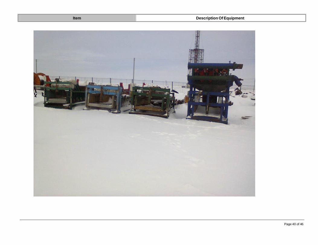
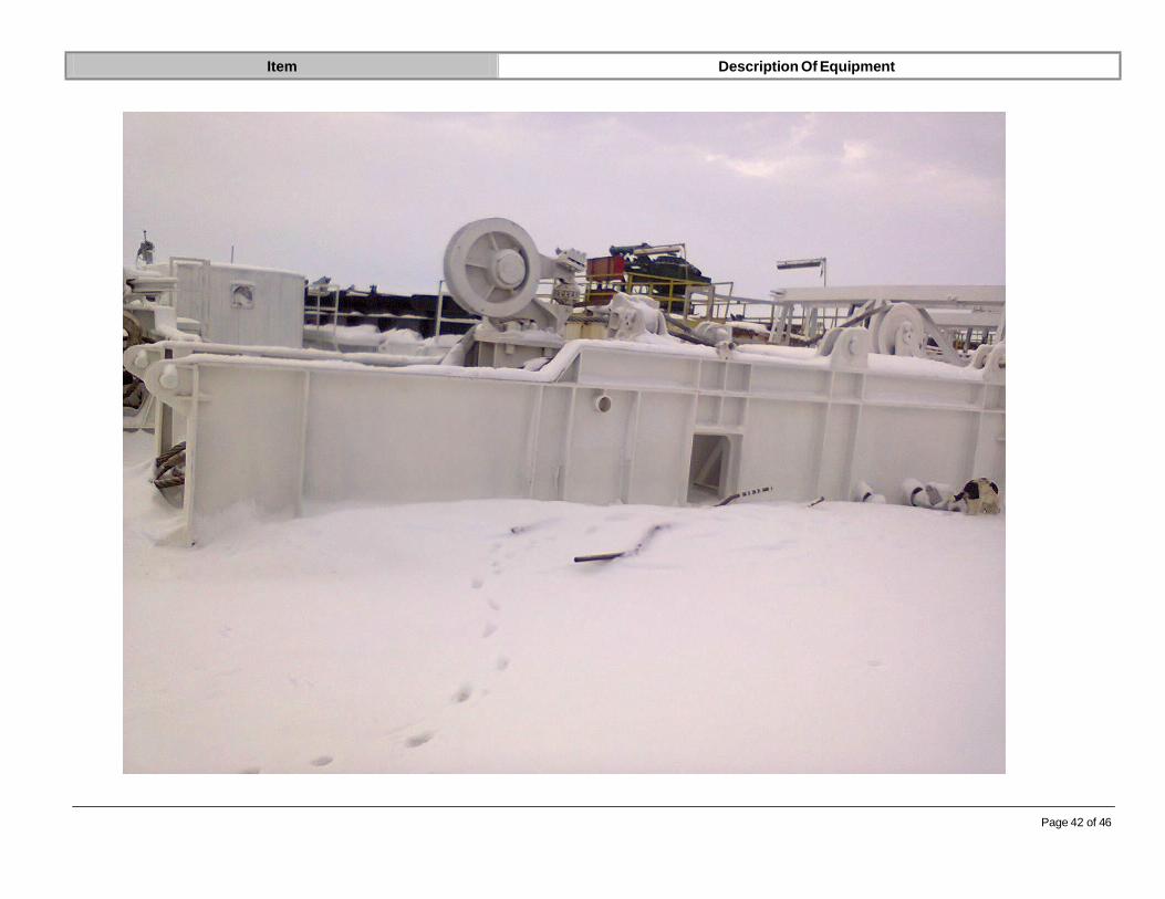
14 Photos
Main camp: 60 Beds
Accommodation Units for 60 men with sufficient beds, bathrooms and showers. With hot and cold water fully plumbed to sewage treatment plant and graywater tank.
Changing rooms and recreational areas to be included.
Canteen and dining hall complete llwith required equipment, furniture, A/C, heaters
Fully equipped field-clinic, complete with bed, hot/cold running water.
Domestic Waste and Trash collection Skips
Gate/Security house 10' x 10' with table and chair

Item Description Of Equipment
Page 34 of 46

Item Description Of Equipment
Page 35 of 46

Item Description Of Equipment
Page 36 of 46

Item Description Of Equipment
Page 37 of 46

Item Description Of Equipment
Page 38 of 46

Item Description Of Equipment
Page 39 of 46
Item Description Of Equipment
Page 40 of 46

Item Description Of Equipment
Page 41 of 46
Item Description Of Equipment
Page 42 of 46

Item Description Of Equipment
Page 43 of 46

Item Description Of Equipment
Page 44 of 46

Item Description Of Equipment
Page 45 of 46

Item Description Of Equipment
Page 46 of 46