technical research report - drum.lib.umd.edu
TRANSCRIPT

TECHNICAL RESEARCH REPORT
The Hybrid Motor Prototype: Design Details and DemonstrationResults
by R. Venkataraman, W.P. Dayawansa,P.S. Krishnaprasad
CDCSS T.R. 98-2(ISR T.R. 98-2)
CENTER FOR DYNAMICSAND CONTROL OF
SMART STRUCTURES
C
S
D+
-
The Center for Dynamics and Control of Smart Structures (CDCSS) is a joint Harvard University, Boston University, University of Maryland center,supported by the Army Research Office under the ODDR&E MURI97 Program Grant No. DAAG55-97-1-0114 (through Harvard University). This
document is a technical report in the CDCSS series originating at the University of Maryland.
Web site http://www.isr.umd.edu/CDCSS/cdcss.html

The Hybrid Motor Prototype: Design Details and Demonstration
Results
R.Venkataraman W.P. Dayawansa and P.S. Krishnaprasad
Institute for Systems Research
and Electrical Engineering Department
University of Maryland at College Park
College Park MD 20742
�
ABSTRACT
A novel hybrid rotary motor incorporating piezoelectric and magnetostrictive actuators1 has been designedand demonstrated. The novelty of this motor was the creation of an electrical resonant circuit, whereby reactivepower requirement on the power source is reduced. It was envisaged that the motor would be suitable for lowoutput speed, high torque applications because of its design. This report presents the constructional details ofthis motor and the results of the demonstration.
1 Introduction
The motivation behind the development of a novel hybrid rotary motor was described in an earlier report.1
It was shown that electrically, the piezoelectric and magnetostrictive actuators behave like a capacitor and aninductor respectively. Thus by creating an electrical resonant circuit, the reactive power requirement on thepower source is reduced. The report contained theoretical modeling of the hybrid motor taking into accountimpact e�ects, sti�ness properties of the materials used, eddy current e�ects in the magnetostrictive materialetc. Computer simulations were carried out to show the feasibility of the concept. Because of the extremelysmall displacements involved (of the order of microns), building a prototype motor was an exciting engineeringchallenge. The design and construction was carried out at the Physics Shop at the University of Maryland atCollege Park (UMCP), while the testing and demonstration was done at the Intelligent Servosystems Laboratoryat UMCP. This report details the design features of a prototype hybrid motor (Figure 1) and the results of itssuccessful demonstration.
�This research was supported in part by a grant from the National Science Foundation's Engineering Research Centers Program:NSFD CDR 8803012, and by the Army Research O�ce under Smart Structures URI Contract No. DAAL03-92-G0121 and underthe MURI97 Program Grant No. DAAG55-97-1-0114 to the Center for Dynamics and Control of Smart Structures (through HarvardUniversity).

Figure 1: The prototype hybrid motor.
2 Basic Principle of Operation
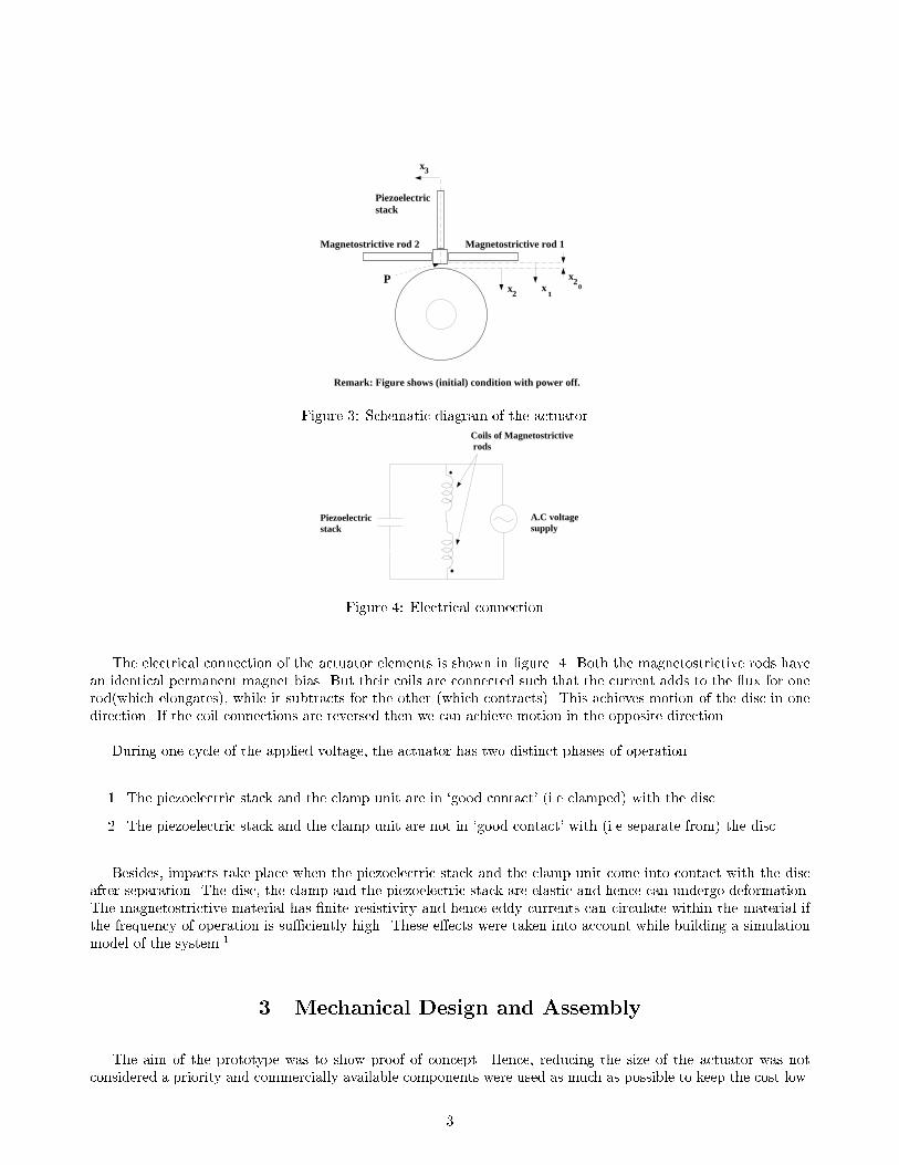
Before we discuss to the technical details of the prototype hybrid motor, we �rst look at its principle ofoperation. The basic scheme of the proposed actuator is shown in �gure 2. The piezoelectric stack clampsthe mass m to the disc while the magnetostrictive rod pushes the mass tangential to the disc. As the angulardisplacement of a disc of radius 5 cm in one such push is of the order of 10�4 radians, we can achieve an appreciabledisplacement per second by operating at su�ciently high frequency. We can use another magnetostrictive rod asshown in �gure 3 to achieve bi-directional motion. In �gure 3, rod 2 contracts in length when rod 1 expandsand vice versa.
Hub of thedisk
Disk
Magnetostrictive rodClamp
Piezoelectricstack
Figure 2: Basic scheme for an unidirectional hybrid motor.
2
Piezoelectricstack
Magnetostrictive rod 1Magnetostrictive rod 2
Remark: Figure shows (initial) condition with power off.
x3
2x1
x2x
0P
Figure 3: Schematic diagram of the actuator.Coils of Magnetostrictive rods
Piezoelectricstack
A.C voltage supply
Figure 4: Electrical connection.
The electrical connection of the actuator elements is shown in �gure 4. Both the magnetostrictive rods havean identical permanent magnet bias. But their coils are connected such that the current adds to the ux for onerod(which elongates), while it subtracts for the other (which contracts). This achieves motion of the disc in onedirection. If the coil connections are reversed then we can achieve motion in the opposite direction.
During one cycle of the applied voltage, the actuator has two distinct phases of operation.
1. The piezoelectric stack and the clamp unit are in `good contact' (i.e clamped) with the disc.
2. The piezoelectric stack and the clamp unit are not in `good contact' with (i.e separate from) the disc.
Besides, impacts take place when the piezoelectric stack and the clamp unit come into contact with the discafter separation. The disc, the clamp and the piezoelectric stack are elastic and hence can undergo deformation.The magnetostrictive material has �nite resistivity and hence eddy currents can circulate within the material ifthe frequency of operation is su�ciently high. These e�ects were taken into account while building a simulationmodel of the system.1
3 Mechanical Design and Assembly
The aim of the prototype was to show proof of concept. Hence, reducing the size of the actuator was notconsidered a priority and commercially available components were used as much as possible to keep the cost low.
3
Though the basic scheme of the hybrid motor is simple, the constructional details of the prototype are quitecomplex.1 Since the elongation of the piezoelectric stack and the magnetostrictive actuator is in the order ofmicrons, initial adjustments are crucial to the motor's performance. To be able to make the required adjustmentsand keep the cost of the prototype motor low, compromises had to be made leading to simplicity of design.
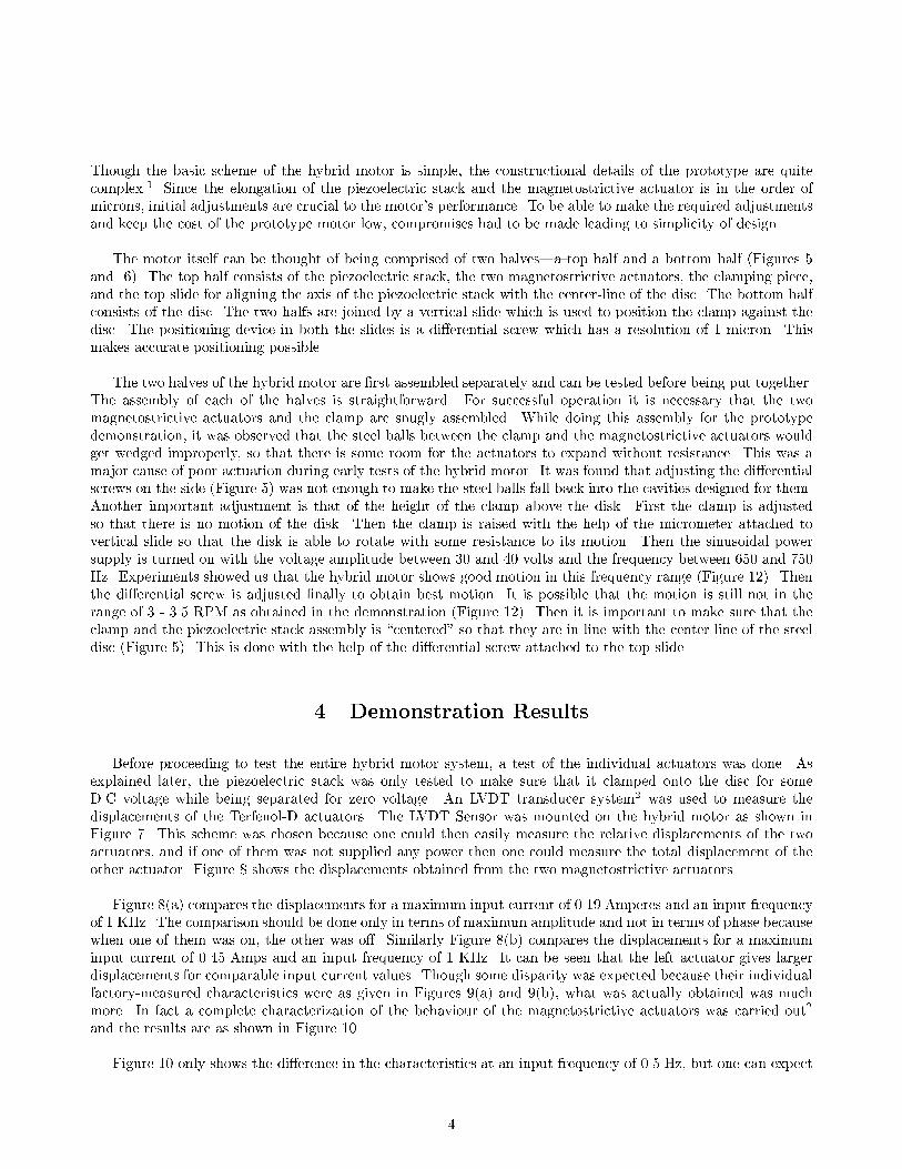
The motor itself can be thought of being comprised of two halves|a top half and a bottom half (Figures 5and 6). The top half consists of the piezoelectric stack, the two magnetostrictive actuators, the clamping piece,and the top slide for aligning the axis of the piezoelectric stack with the center-line of the disc. The bottom halfconsists of the disc. The two halfs are joined by a vertical slide which is used to position the clamp against thedisc. The positioning device in both the slides is a di�erential screw which has a resolution of 1 micron. Thismakes accurate positioning possible.
The two halves of the hybrid motor are �rst assembled separately and can be tested before being put together.The assembly of each of the halves is straightforward. For successful operation it is necessary that the twomagnetostrictive actuators and the clamp are snugly assembled. While doing this assembly for the prototypedemonstration, it was observed that the steel balls between the clamp and the magnetostrictive actuators wouldget wedged improperly, so that there is some room for the actuators to expand without resistance. This was amajor cause of poor actuation during early tests of the hybrid motor. It was found that adjusting the di�erentialscrews on the side (Figure 5) was not enough to make the steel balls fall back into the cavities designed for them.Another important adjustment is that of the height of the clamp above the disk. First the clamp is adjustedso that there is no motion of the disk. Then the clamp is raised with the help of the micrometer attached tovertical slide so that the disk is able to rotate with some resistance to its motion. Then the sinusoidal powersupply is turned on with the voltage amplitude between 30 and 40 volts and the frequency between 650 and 750Hz. Experiments showed us that the hybrid motor shows good motion in this frequency range (Figure 12). Thenthe di�erential screw is adjusted �nally to obtain best motion. It is possible that the motion is still not in therange of 3 - 3.5 RPM as obtained in the demonstration (Figure 12). Then it is important to make sure that theclamp and the piezoelectric stack assembly is \centered" so that they are in line with the center line of the steeldisc (Figure 5). This is done with the help of the di�erential screw attached to the top slide.
4 Demonstration Results
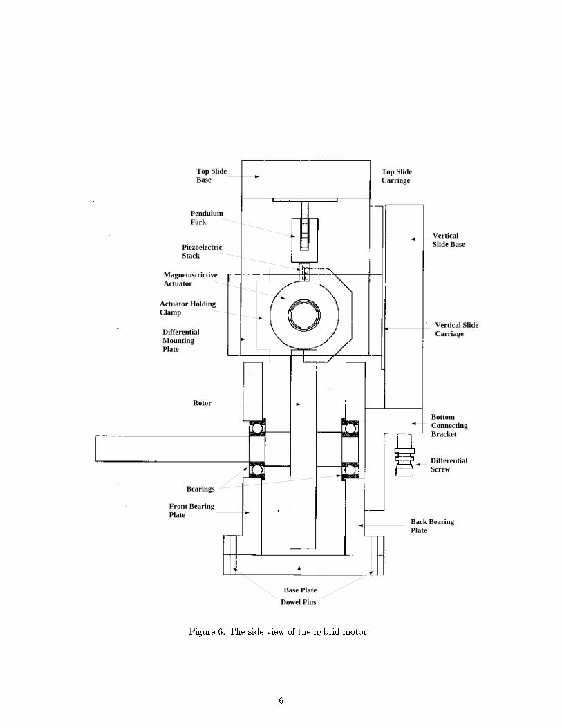
Before proceeding to test the entire hybrid motor system, a test of the individual actuators was done. Asexplained later, the piezoelectric stack was only tested to make sure that it clamped onto the disc for someD.C voltage while being separated for zero voltage. An LVDT transducer system2 was used to measure thedisplacements of the Terfenol-D actuators. The LVDT Sensor was mounted on the hybrid motor as shown inFigure 7. This scheme was chosen because one could then easily measure the relative displacements of the twoactuators, and if one of them was not supplied any power then one could measure the total displacement of theother actuator. Figure 8 shows the displacements obtained from the two magnetostrictive actuators.
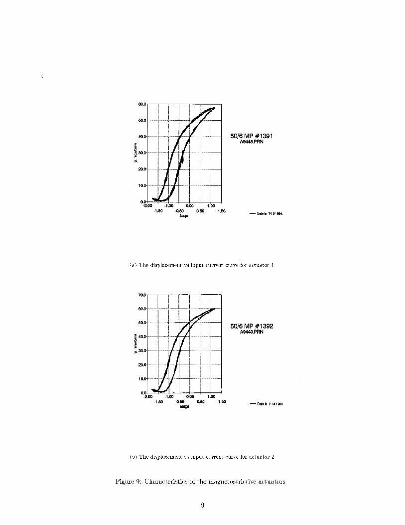
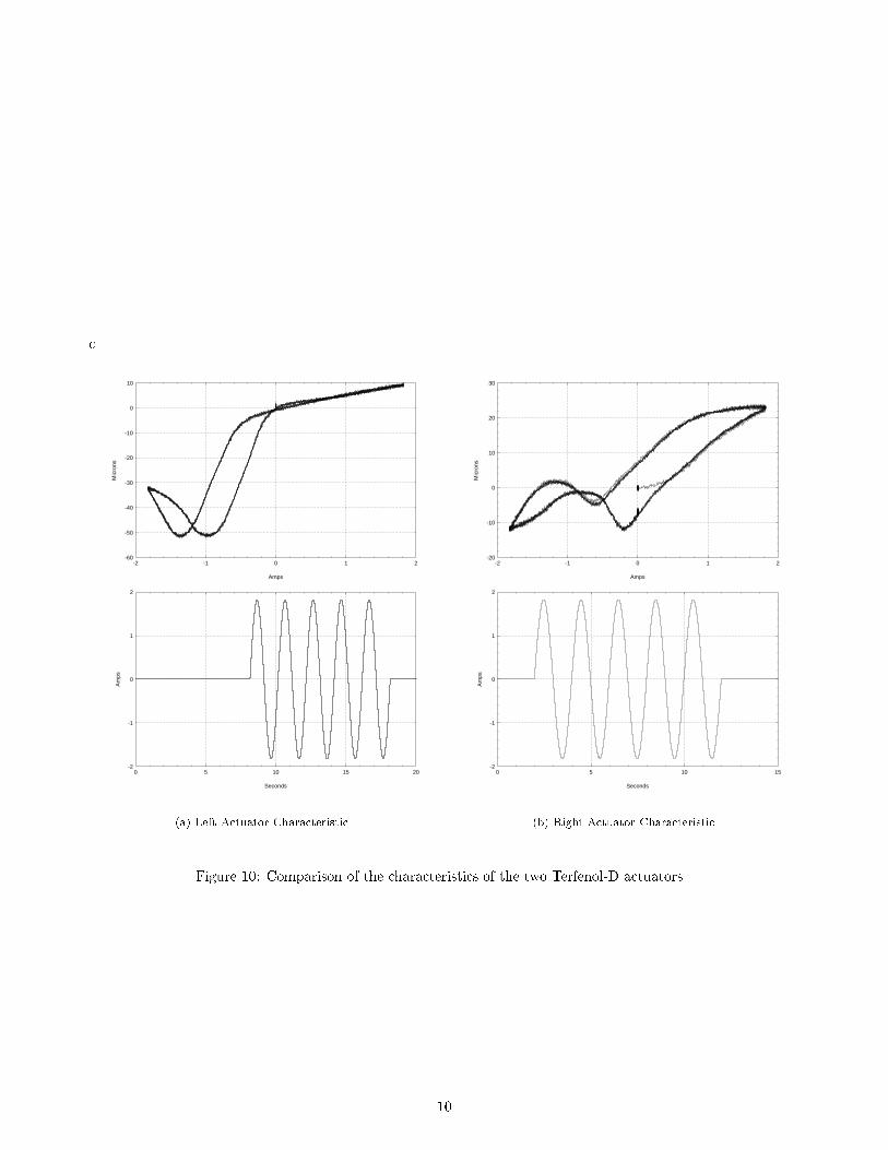
Figure 8(a) compares the displacements for a maximum input current of 0.19 Amperes and an input frequencyof 1 KHz. The comparison should be done only in terms of maximum amplitude and not in terms of phase becausewhen one of them was on, the other was o�. Similarly Figure 8(b) compares the displacements for a maximuminput current of 0.45 Amps and an input frequency of 1 KHz. It can be seen that the left actuator gives largerdisplacements for comparable input current values. Though some disparity was expected because their individualfactory-measured characteristics were as given in Figures 9(a) and 9(b), what was actually obtained was muchmore. In fact a complete characterization of the behaviour of the magnetostrictive actuators was carried out2
and the results are as shown in Figure 10.
Figure 10 only shows the di�erence in the characteristics at an input frequency of 0.5 Hz, but one can expect
4

MagnetostrictiveActuator
Differential Screw
Top Slide
Left ActuatorHolder
MagnetostrictiveActuator
Rotor
PiezostrictiveStack
Pendulum ForkPendulum Mount
Bearing
Right ActuatorHolder
Base Plate
Base Spacer
Base Spacer
Differential ScrewMounting Plate
Differential Screw Mounting Plate
BronzeClamp
DifferentialScrew
Differential ScrewSupport Plate
Differential ScrewSupporting Plate
Figure
5:Thefro
ntview
ofthehybrid
motor.
5
VerticalSlide Base
Vertical SlideCarriage
Top Slide Base
Top SlideCarriage
PendulumFork
PiezoelectricStack
MagnetostrictiveActuator
BottomConnectingBracket
DifferentialScrew
Back BearingPlate
Base Plate
Dowel Pins
Front BearingPlate
Rotor
Bearings
Actuator HoldingClamp
DifferentialMountingPlate
Figure 6: The side view of the hybrid motor.
6
+ -
+
-
MagneotstrictiveActuator 1
Magnetostrictive Actuator 2
Clamp
LVDT coil housingLVDT core
LVDT differentialvoltage output
D.C VoltageInput
Figure 7: Schematic of the displacement sensing by the LVDT sensor.c
Left Actuator Right Actuator
0 0.5 1 1.5 2 2.5 3 3.5 4 4.5
x 10−3
−6
−5
−4
−3
−2
−1
0
1
2
3
4
Seconds
Mic
rons
Imax = 0.19 Amperes
(a) The displacements for Imax = 0.19 Amps.
Left Actuator Right Actuator
0 0.5 1 1.5 2 2.5 3 3.5 4 4.5
x 10−3
−15
−10
−5
0
5
10
15
Seconds
Mic
rons
Imax = 0.45 Amperes
(b) The displacements for Imax = 0.45 Amps.
Figure 8: Comparison of the maximum displacements of the two Terfenol-D actuators.
a similar disparity at high frequencies also (Figure 8). (By left actuator we mean the actuator that is to our leftas we view the hybrid motor from the front.) So we can conclude that the left actuator is working as expectedwhile the right actuator is not. The testing of the hybrid motor was done in spite of this de�ciency.
As was mentioned before in the section on basic principle of operation (Figure 4), it is necessary that the twomagnetostrictive actuators be connected electrically, so that the ux adds to the permanent magnet bias for oneof them and subtracts for the other. Figure 11 shows the net displacements obtained for two di�erent connectionsof the actuators. Ideally, we would like one of them to be zero, but in our case, we have to choose the connectionwith the lower relative displacement, and consistently use this for all the later experiments.
For successful operation of the motor, it is enough that the piezoelectric stack extend su�ciently to clampthe disc, while separating from it during the other half cycle. By the design, one can see that the placement ofthe top half with respect to the bottom half is critical in making sure that both clamping and separation occur.Hence in the actual demonstration, the placement of the top half was carried out with power being supplied tothe device, the criterion being most rotary motion at some frequency of operation. Figure 12 shows the variation
7
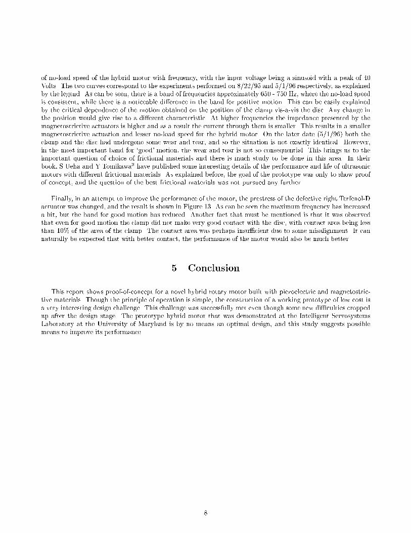
of no-load speed of the hybrid motor with frequency, with the input voltage being a sinusoid with a peak of 40Volts. The two curves correspond to the experiments performed on 8/22/95 and 5/1/96 respectively, as explainedby the legend. As can be seen, there is a band of frequencies approximately 650 - 750 Hz, where the no-load speedis consistent, while there is a noticeable di�erence in the band for positive motion. This can be easily explainedby the critical dependence of the motion obtained on the position of the clamp vis-a-vis the disc. Any change inthe position would give rise to a di�erent characteristic. At higher frequencies the impedance presented by themagnetostrictive actuators is higher and as a result the current through them is smaller. This results in a smallermagnetostrictive actuation and lesser no-load speed for the hybrid motor. On the later date (5/1/96) both theclamp and the disc had undergone some wear and tear, and so the situation is not exactly identical. However,in the most important band for `good' motion, the wear and tear is not so consequential. This brings us to theimportant question of choice of frictional materials and there is much study to be done in this area. In theirbook, S.Ueha and Y.Tomikawa3 have published some interesting details of the performance and life of ultrasonicmotors with di�erent frictional materials. As explained before, the goal of the prototype was only to show proofof concept, and the question of the best frictional materials was not pursued any further.
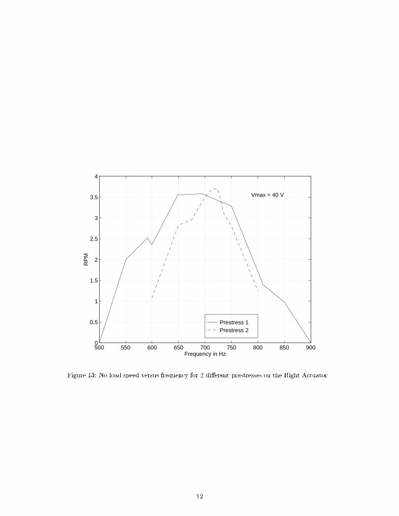
Finally, in an attempt to improve the performance of the motor, the prestress of the defective right Terfenol-Dactuator was changed, and the result is shown in Figure 13. As can be seen the maximum frequency has increaseda bit, but the band for good motion has reduced. Another fact that must be mentioned is that it was observedthat even for good motion the clamp did not make very good contact with the disc, with contact area being lessthan 10% of the area of the clamp. The contact area was perhaps insu�cient due to some misalignment. It cannaturally be expected that with better contact, the performance of the motor would also be much better.
5 Conclusion
This report shows proof-of-concept for a novel hybrid rotary motor built with piezoelectric and magnetostric-tive materials. Though the principle of operation is simple, the construction of a working prototype of low cost isa very interesting design challenge. This challenge was successfully met even though some new di�culties croppedup after the design stage. The prototype hybrid motor that was demonstrated at the Intelligent ServosystemsLaboratory at the University of Maryland is by no means an optimal design, and this study suggests possiblemeans to improve its performance.
8
c
(a) The displacement vs input current curve for actuator 1.
(b) The displacement vs input current curve for actuator 2.
Figure 9: Characteristics of the magnetostrictive actuators.
9
c
Amps
-1 0 1-2 2
Mic
rons
-50
-40
-30
-20
-10
0
-60
10
Seconds
5 10 150 20
Am
ps
-1
0
1
-2
2
(a) Left Actuator Characteristic.
Amps
-1 0 1-2 2
Mic
rons
-10
0
10
20
-20
30
Seconds
5 100 15
Am
ps
-1
0
1
-2
2
(b) Right Actuator Characteristic.
Figure 10: Comparison of the characteristics of the two Terfenol-D actuators.
10

c
0 0.5 1 1.5 2 2.5 3 3.5 4 4.5
x 10−3
−8
−6
−4
−2
0
2
4
6
8
10
Seconds
Mic
rons
Imax = 0.32 Amperes
(a) The displacements for the black wires tiedtogether.
0 0.5 1 1.5 2 2.5 3 3.5 4 4.5
x 10−3
−30
−20
−10
0
10
20
30
Seconds
Mic
rons
Imax = 0.32 Amperes
(b) The displacements for one black and other redwire tied together.
Figure 11: Net displacements obtained with two di�erent connections of the Terfenol-D actuators.
8/22/955/1/96
400 500 600 700 800 900 1000 11000
0.5
1
1.5
2
2.5
3
3.5
4
Frequency in Hz
RP
M
Vmax = 40 V
Figure 12: Variation of No-load speed with driving frequency.
11
Prestress 1Prestress 2
500 550 600 650 700 750 800 850 9000
0.5
1
1.5
2
2.5
3
3.5
4
Frequency in Hz
RP
M
Vmax = 40 V
Figure 13: No load speed versus frequency for 2 di�erent prestresses on the Right Actuator.
12

6 REFERENCES
[1] R. Venkataraman, \A hybrid actuator," Master's thesis, University of Maryland at College Park, May 1995.
[2] R. Venkataraman, J. Rameau, and P. Krishnaprasad., \Characterization of the Etrema MP50/6 magne-tostrictive actuator." To be published as a technical report of the Institute for Systems Research, Universityof Maryland at College Park.
[3] S. Ueha and Y. Tomikawa, Ultrasonic Motors: Theory and Applications. Clarendon Press, Oxford, 1993.
13