technical report udc 669 . 14 - 462 . 2 : 621 . 791 . 011 ... · technical report udc 669 . 14 -...
TRANSCRIPT

NIPPON STEEL & SUMITOMO METAL TECHNICAL REPORT No. 107 FEBRUARY 2015
- 127 -
1. Introduction Line pipes are usually joined together by girth welding. The
weld zone consists of the weld metal and heat affected zone (HAZ). The weld metal differs in composition from the base metal because it is a mixture of the base metal and welding consumables. HAZ dif-fers in microstructure and properties from the base metal because of the thermal history during welding. Therefore, every pipe manufac-turer must have a store of knowledge about weld metals, the proper-ties of weld zones (including HAZ), and pipe base metals. In partic-ular, when constructing a natural gas or crude oil pipeline, field girth welding efficiency and appropriate weld zone properties are key to the success of the project. Therefore, there is a strong need to evalu-ate the girth weldability of line pipe.
When collecting data about weld zone properties, it is necessary to carry out girth welding and prepare girth-welded joints. In this case, there are mainly two types of welded joints the pipe manufac-turer is required to prepare. One type is obtained under conditions as close as possible to actual field welding conditions. Welded joints of this type are often demanded by pipeline construction contractors. The welding of line pipes began in the United States. Around 1945, a combination of the spread method and efficient manual welding using a high cellulose-type welding rod was established as the weld-ing method for onland pipelines.
Since then, in order to save labor through automated welding operations and to improve welding efficiency, efforts have been made to narrow the welding grooves. The current mainstream is high-efficiency welding that combines gas metal arc welding and a groove angle of 5° or less.1) For the welding material, a thin, solid wire 0.9 to 1.2 mm in diameter is used. In many cases, downward welding is applied. Welding heat input is as low as around 0.3 kJ/mm to 1.5 kJ/mm.2, 3) By applying downward welding, it is possible to increase welding speed and shorten welding time per pass, there-by enhancing welding efficiency. This allows for a low heat input. In addition, a relatively high interpass temperature is used to shorten wait time.
The other welded joint type is welded joints of HAZ used to evaluate performance. In this case, unlike in actual welding, a half K bevel-shaped groove, one side of which is vertical, is used, and the welding line is kept linear. In addition, the welding is required to be performed with maximum and minimum heat inputs that can be applied at the construction site. These demands often come from oil and gas companies who are the final users of line pipes.
In this report, the author presents the results of a simulative test of field girth welding on X80 UOE pipe using gas metal arc welding with a narrow groove, and the results of evaluations of the proper-ties of girth-welded HAZ joints of X65 seamless pipe with a half K
Technical Report UDC 669 . 14 - 462 . 2 : 621 . 791 . 011
* General Manager, Head of Dept., Welding Joint Marketing & Development Dept., Joint Marketing & Development Div., Wakayama Works 1850 Minato, Wakayama City, Wakayama Pref. 640-8555
Development of Field Girth Welding Simulation and Test Procedure Development to Evaluate Pipe Properties at HAZ
in Girth Welded PortionMasahiko HAMADA* Hiroyuki NAGAYAMANaoki KURODA Yuuki WATATANIHidenori SHITAMOTO Yoshiyuki MATSUHIRO
AbstractIt is important controlling properties in welded portion generated by field girth welding.
Thus Nippon Steel & Sumitomo Metal Corporation is conducting two developments about the girth welding. The first one is simulation technique of the field girth welding, it is called “field girth welding simulation”. The second one is a test procedure development to evaluate properties of weld heat affected zone generated in pipe body, it is called “weldability test”. A field girth welding simulation on X80 UOE pipe and a weldability test on X65 seamless pipe are reported in this paper.

NIPPON STEEL & SUMITOMO METAL TECHNICAL REPORT No. 107 FEBRUARY 2015
- 128 -
bevel-shaped groove.
2. Simulation of Field Girth Welding and Evaluation of Weld Zones, Using X80 UOE Pipe
2.1 Specimen and girth welding methodThe test used an X80 UOE pipe 610 mm in outside diameter and
15.6 mm in wall thickness. The chemical composition of the pipe base metal is shown in Table 1. The pipe material was a low carbon steel added with Mn, Cu, Ni, Cr, Mo, Nb, V and Ti. The Pcm was 0.18 mass%.
To simulate field girth welding, gas-shielded metal arc welding with a narrow groove was applied. Figure 1 shows the groove shape used. In the present case of welding, in order to simulate root run-ning from the inside, a groove shape with one stage on the inside and two stages on the outside was adopted. As shown in Fig. 1, the main bevel angle was 5°. Fig. 1 also shows the pass sequence. A one-layer, one-pass sequence — the most popular for field girth welding — was adopted.
The girth welding conditions used are shown in Table 2. For root running, semiautomatic gas-shielded metal arc welding was performed from the inside. During root running, the pipe was held on a clamp from the outside and turned while it was welded. In the
second and succeeding passes, downward welding was applied from the outside with the pipe fixed. The welding process was pulsed gas metal arc welding. Welding conditions are shown in Table 2. In the second pass (hot pass), 100% CO2 was used as the shielding gas in order to ensure sufficient penetration. In the first pass (root pass), ar-gon-25%CO2 was used as the shielding gas, whereas argon-30%CO2 was used in the third (fill) and fourth (cap) passes. Mixed gases were used in order to inhibit an increase in oxygen content in the weld metal, and thereby secure sufficient weld metal toughness. The welding wire was a solid wire 1.0 mm in diameter, equivalent to AWS A5.18 ER70S-G. A Gr70-equivalent welding wire was applied to the X80 pipe in order to permit even-match welding, with consid-eration given to the increase in strength with low welding heat input. Table 3 shows the results of a chemical analysis of the girth weld metal. Pcm was 0.19 mass%, nearly the same as that of the base metal. Oxygen content was controlled at 0.03%.2.2 Cross-section macrostructure of weld zone; hardness distri-
bution in weld zoneFigure 2 shows the cross-section macrostructure of a prepared
welded joint, and points of hardness measurements. The cross-sec-tion macrostructure is characteristic of field girth welding: a small welding width, and a small cross-sectional area of weld metal.
Weld metal hardness was measured at three points: through-thickness at the center, 1 mm from the pipe inner surface, and 1 mm from the pipe outer surface. The hardness of the weld metal center cyclically varied (see Fig. 3) under the influence of cyclic heating in multilayer welding. Maximum hardness was HV 274; minimum hardness, HV 219; and average hardness, HV 244. At the three meas uring points shown in Fig. 4, the base metal did not demon-strate any significant difference in hardness, the average hardness being HV 251. The weld metal and base metal were nearly the same
Table 1 Chemical compositions of base metal of X80 UOE pipe(mass%)
C Si Mn P S0.06 0.14 1.72 0.006 0.0012
Others Ceq (IIW) PcmCu, Ni, Cr, Mo, Nb, V, Ti 0.43 0.18
Table 2 Welding procedures
Pass Root (inside) Hot Fill - capProcess Semi-auto GMAW PGMAWPosition 1G 5G 5G
EquipmentDAIHENDM-350
RMS RMS
Welding wireNippon-Sumitomo YM-SCV (1.0 mm)
(Eq. AWS 5.18 ER70S-G)Shielding gas 75%Ar-25%CO2 100%CO2 70%Ar-30%CO2
Heat input(kJ/mm)
— 0.3 0.4 – 0.7
NotePreheating was not applied.
Inter pass temp < 100 ˚C
Table 3 Chemical compositions of girth weld metal(mass%)
C Si Mn P S0.069 0.71 1.48 0.009 0.005
Cu Ni Cr Mo V0.31 0.04 0.04 0.02 0.01Ti Nb B Sol-Al Insol-Al
0.002 0.008 0.0006 0.008 < 0.001O N Pcm Ceq (IIW)
0.03 0.0033 0.19 0.35Fig. 1 Bevel preparation and pass sequence
Fig. 2 Macro structure and measurement lines of hardness distribution
NIPPON STEEL & SUMITOMO METAL TECHNICAL REPORT No. 107 FEBRUARY 2015
- 129 -
in hardness. Thus, it was confirmed that the aimed-for even-match welded joint could be obtained. The increase in HAZ hardness was minimal, and a slight decrease in HAZ hardness was observed. Minimum HAZ hardness was HV 219, or 87% of the average base metal hardness.2.3 Weld zone tensile properties
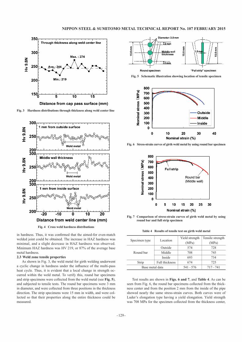
As shown in Fig. 3, the weld metal for girth welding underwent a cyclic change in hardness under the influence of the multi-pass heat cycle. Thus, it is evident that a local change in strength oc-curred within the weld metal. To verify this, round bar specimens and strip specimens were collected from the weld metal (see Fig. 5), and subjected to tensile tests. The round bar specimens were 3 mm in diameter, and were collected from three positions in the thickness direction. The strip specimens were 15 mm in width, and were col-lected so that their properties along the entire thickness could be measured.
Test results are shown in Figs. 6 and 7, and Table 4. As can be seen from Fig. 6, the round bar specimens collected from the thick-ness center and from the position 2 mm from the inside of the pipe showed nearly the same stress-strain curves. Both curves were of Luder’s elongation type having a yield elongation. Yield strength was 708 MPa for the specimen collected from the thickness center,
Fig. 3 Hardness distributions through thickness along weld center line
Fig. 4 Cross weld hardness distributions
Fig. 5 Schematic illustration showing location of tensile specimen
Fig. 6 Stress-strain curves of girth weld metal by using round bar specimen
Fig. 7 Comparison of stress-strain curves of girth weld metal by using round bar and full strip specimen
Table 4 Results of tensile test on girth weld metal
Specimen type LocationYield strength
(MPa)Tensile strength
(MPa)
Round barOutside 574 728Middle 708 745Inside 693 734
Strip Full thickness 674 725Base metal data 541 – 576 717 – 741

NIPPON STEEL & SUMITOMO METAL TECHNICAL REPORT No. 107 FEBRUARY 2015
- 130 -
and 693 MPa for the specimen collected from a position 2 mm from the inside of the pipe. The round bar specimen collected from a po-sition 2 mm from the outside of the pipe did not show any yield elongation, and its stress-strain curve was of the round house type. The yield strength of this specimen was 574 MPa, lower than that of the other two round bar specimens. The difference in S-S curves is probably due to the fact that in the last pass the weld metal main-tained its microstructure as solidification-hardened, since it was not reheated by any succeeding welding pass. On the other hand, the strip specimen showed a stress-strain curve of Luder’s elongation type, and had the yield elongation shown in Fig. 7. The yield strength of this specimen was 674 MPa. Thus, it was confirmed that a round bar specimen collected from the thickness center would produce nearly the same test results as other specimens collected from any other position.
As summarized in Table 4, the tensile test results revealed that the welded joints are an even match with the base metal in tensile strength, but exceed the base metal in yield strength by about 20%. There is a controversy over whether tensile strength or yield strength should be used to define strength matching between the base metal and the weld metal in a welded joint. In recent years, studies have been conducted to determine which of the two definitions is valid, and have included comparative studies using FEA.
Figure 8 shows the appearance of a strip specimen after it frac-tured in a tensile test. The fracture occurred at a base metal part way from the weld zone, indicating that the welded joint had no prob-lems as far as fracture mode is concerned.2.4 Charpy and CTOD test results
Two notches in the weld metal centerline and fusion line (FL: HAZ = 50:50) were subjected to a Charpy impact test. Test results are shown in Fig. 9. At the FL, a high energy value over 100J was obtained at a temperature as low as −60°C. The ductility-brittleness transition temperature was −53°C. At the notch in the weld metal centerline, energy values were generally smaller than those at the notch in the FL. This is due to the fact that the oxygen content of the weld metal (0.03 mass%) was one digit higher than that of the base metal. Oxygen in steel forms oxides which induce ductile fractures and cause the energy value in 100% ductile fractures to decrease. However, it was confirmed that the ductility-brittleness transition temperature at the notch in the weld metal centerline was lower than −60°C, indicating that the weld metal has sufficient toughness.
A CTOD test was carried out at −10°C. The notch positions were on the weld metal centerline and FL, as in the Charpy impact test.
The CTOD test results are shown in Table 5. CTOD values for the weld metal centerline notch were 0.32 mm, 0.35 mm and 0.33 mm, and those for the FL notch were 0.40 mm, 0.61 mm and 0.34 mm. All specimens fractured at 100% ductility, proving that the weld zones had excellent crack resistance.
3. Evaluation of HAZ Properties in Girth Welding with Half K bevel-Shaped Groove
3.1 Purpose for performing welding with half K bevel-shaped grooveWhen performing girth welding or any other type of welding, it
is common practice to prepare a groove and fill it with fused weld-ing wire or the like. Therefore, in order to evaluate the Charpy and CTOD characteristics of a coarse-grain HAZ (CGHAZ) formed along the fusion line using ordinary welded joints, for example, the notches for Charpy and CTOD tests are prepared so that the ratio of weld metal to HAZ in each of the notches becomes 50:50, as de-scribed in Section 2.4. In this case, the notch may contain not only a CGHAZ but also a fine-grain HAZ (FGHAZ) and weld metal. If so, it is not always possible to evaluate the actual CGHAZ properties.
It is generally thought that in multi-pass welded joints, the parts whose toughness declines most are the CGHAZ and the intercritical reheated CGHAZ (ICCGHAZ), which is the CGHAZ reheated to the midpoint between Ac3 and Ac1 during the subsequent welding heat cycle. Therefore, as a means of accurately evaluating the CTOD characteristics of HAZ, in particular, API-RP2Z recommends preparing welded joints with a half K bevel-shaped groove to in-crease the proportion of CGHAZ and ICCGHAZ at the notch. In the present study, with reference to RP2Z, the author and collaborators evaluated the HAZ characteristics of joints which met the following requirements:
(1) Irregularities in the fusion line: within 1.0 mm(2) Average distance between notch and fusion line: 0.5 mm or
less(3) Proportion of HAZ in notch: 80% or more
Table 5 CTOD test results
Notch locationTemp.(˚C)
CTOD value(mm)
Weld center line −10 0.32, 0.35, 0.33Fusion line −10 0.40, 0.61, 0.34
Fig. 8 Fracture appearance after the cross weld tensile tests Fig. 9 Charpy impact test results at welded portion

NIPPON STEEL & SUMITOMO METAL TECHNICAL REPORT No. 107 FEBRUARY 2015
- 131 -
(4) Proportion of CGHAZ and ICCGHAZ adjoining fusion line: 25% or more
(All of the above requirements apply to the central 60% of the wall thickness or specimen thickness.)3.2 Specimens and girth welding method
The material welded was an X65 seamless pipe 219.1 mm in outside diameter and 33.45 mm in wall thickness. Welding condi-tions are shown in Table 6. Two levels of welding heat input were tested: 0.5 kJ/mm (low heat input), and 1.6 kJ/mm (high heat input). At both levels of heat input, the pipe was rotated while being weld-ed. For welding with the low heat input, pulsed gas metal arc weld-ing was used, with the preheating and interpass temperatures kept below 50°C. For welding with the high heat input, submerged arc welding was used, with the preheating and interpass temperatures controlled within a range of 125°C to 150°C. As mentioned in the Introduction, a low heat input (0.3 kJ/mm ~ 1.5 kJ/mm) is often used for the girth welding of line pipes. The author considers that the welding conditions selected in the present study almost entirely cover the conditions used in field girth welding operations. The welding groove was a deformed half K bevel-shaped groove, one side being vertical and the other side two-staged, as shown in Fig. 10.3.3 Microstructures of weld zone cross sections
Figure 11 shows sample microstructures of the prepared welded joint cross sections. Table 7 shows the results of measurements of irregularities in the fusion line (HAZ straightness) and the propor-tions of CGHAZ and ICCGHAZ adjoining the fusion line. It was confirmed that the joints obtained by gas metal arc welding with low heat input and the joints obtained by submerged arc welding with high heat input both attained the aimed-for HAZ straightness and microstructure.
Next, the author and collaborators studied the relationship be-tween average notch-FL distance and the proportion of HAZ in the
notch. Results are shown in Fig. 12. To accurately evaluate the CTOD characteristics of CGHAZ/ICCGHAZ, it is desirable that the notch should be as close to the fusion line as possible. However, if the notch is too close to the fusion line, the proportion of weld metal in the notch becomes too large to permit evaluation of the CTOD characteristics of the HAZ. As is evident from Fig. 12, when the av-erage distance between notch and fusion line was smaller than 0.2
Table 6 Welding procedures
Low heat input High heat inputProcess Pulsed GMAW SAWPosition Pipe rotated Pipe rotated
Aimed heat input 0.5 kJ/mm 1.6 kJ/mmPreheat/interpass temp. Max. 50˚C 125 – 150˚C
Table 7 HAZ straightness and CGHAZ+ICCGHAZ ratio
WPSJointID
Specimen ID
HAZ straightness(mm)
CGHAZ+ICCGHAZ
(%)
PGMAW0.5 kJ/mm
M-2MW-1 0.76 64.9%MW-2 0.88 66.9%
M-3MW-3 0.68 58.9%MW-4 0.73 62.8%
SAW1.6 kJ/mm
S-2SW-1 0.98 52.5%SW-2 0.85 57.3%
S-3SW-3 0.95 67.1%SW-4 0.56 63.8%
Fig. 10 Example of half K bevel
Fig. 11 Macrographic examination results
Fig. 12 Effect of the average distance from the fusion line and precrack on the HAZ ratio on the precrack

NIPPON STEEL & SUMITOMO METAL TECHNICAL REPORT No. 107 FEBRUARY 2015
- 132 -
mm, the proportion of HAZ in the notch did not always attain the aimed-for 80%. From this it can be seen that, in order to attain the aimed-for values at all times, it is necessary to control the average notch-FL distance within an extremely narrow range of 0.2 mm to 0.5 mm.3.4 CTOD test results
Figure 13 shows the results of a CTOD test in which a notch was introduced near to the fusion line using a half K bevel-shaped groove. In the case of joints obtained by gas metal arc welding with low heat input (0.5 kJ/mm), all three specimens tested at −20°C completely underwent a ductile fracture after the maximum test load was reached, and showed a large CTOD value of 1.0 mm or more. With respect to joints obtained by submerged arc welding with high heat input (1.6 kJ/mm), some specimens broke down at test tempera-tures of −20°C and 0°C before the maximum test load was reached.
However, these breakdowns were due to ductile fractures, and even the smallest CTOD value was 0.25 mm. It was considered, there-fore, that X65 seamless pipe has sufficient crack arrestability as a line pipe.
4. ConclusionWhile discussing the company’s R&D for line pipe girth weld-
ing technology, the author has described the development of tech-niques for simulating, as accurately as possible, girth welding opera-tions performed at pipeline construction sites, and the development of techniques for accurately evaluating the properties (specifically the CTOD properties) of a HAZ produced in a pipe body as a result of welding heat hysteresis. Ever since the crude oil spillage in the Gulf of Mexico in 2010, customer awareness of the need for pipe-line safety is stronger than ever before. In particular, interest in en-suring the properties required of pipeline weld zones is extremely strong.
We consider that it is the responsibility of every pipe manufac-turer who develops, makes and sells pipe bodies to provide custom-ers with pipe application technologies, including new and advanced welding techniques. Paying due attention to customer needs at all times, we are continuing to develop systems for evaluating pipe ap-plication technology, while accumulating relevant knowledge.
References1) Yanaka, K.: Practical Lecture, A Class in Joining & Welding, Pipeline
(Process & Construction). Journal of Japan Welding Society. 80 (3), 30-38 (2011)
2) Hammond, J., Blackman, S. A., Hudson, M. G.: Challenges of Girth Welding X100 Linepipe for Gas Pipeline. Pipe Dreamer’s Conference. 7-8 Nov. 2002, Yokohama, p. 931-955
3) Biery, N. E., Macia, M. L., Appleby, R. J. T., Fairchild, D. P., Hoyt, D. S., Dorling, D., Horcley, D.: Godin Lake Trial: X120 Field Welding. Pro-ceedings of IPC 2006. Sept. 25-29, Calgary, IPC 2006-10397
4) Motohashi, H., Hagiwara, N.: Analytical Study of the Effect of Strength Matching on Strain Capacity, Proceedings of ISDOPE 2007. July 1-6, Lisbon, 3101-3106
Fig. 13 CTOD test results at coarse grain HAZ
Masahiko HAMADAGeneral Manager, Head of Dept.Welding Joint Marketing & Development Dept.Joint Marketing & Development Div.Wakayama Works1850 Minato, Wakayama City, Wakayama Pref. 640-8555Hiroyuki NAGAYAMAWelding Joint Marketing & Development Dept.Joint Marketing & Development Div.Wakayama Works
Naoki KURODAWelding Joint Marketing & Development Dept.Joint Marketing & Development Div.Wakayama Works
Yuuki WATATANIWelding Joint Marketing & Development Dept.Joint Marketing & Development Div.Wakayama Works
Hidenori SHITAMOTOSenior ResearcherSteel Rolling R&D Div. Process Research Laboratories
Yoshiyuki MATSUHIROGeneral ManagerWelding Joint Technology DepartmentQuality and Technology HeadquartersNIPPON STEEL & SUMIKIN Pipeline & Engineer-ing Co. Ltd.