technical report ship hydrodynamics and ... report ship hydrodynamics and mooring analysis berth 6...
TRANSCRIPT

TECHNICAL REPORT SHIP HYDRODYNAMICS AND MOORING ANALYSIS BERTH 6 BULKHEAD EXTENSION PORT OF PORT ARTHUR, TX
Date 12/1/2014 12/12/14 12/30/14 01/08/15
Revision # Draft v0 Draft v1 Draft v2 Final
Author Scott W. Fenical,
P.E., D.CE.
Scott W. Fenical,
P.E., D.CE. Scott W. Fenical, P.E.,
D.CE. Scott W. Fenical, P.E.,
D.CE.
QC Checker Hugo E. Bermudez,
P.E., D.CE. Hugo E. Bermudez,
P.E., D.CE. Hugo E. Bermudez,
P.E., D.CE. Hugo E. Bermudez,
P.E., D.CE. CHE
Project# 345997 345997 345997 345997
D:\Projects\Port of Port Arthur Berth 6 Bulkhead Extension - 345997\Reporting\2015-01-08 FINAL Tech Rpt-PoPA Berth 6 Bulkhead Ext Mooring Analysis.docx

TECHNICAL REPORT SHIP HYDRODYNAMICS AND MOORING ANALYSIS BERTH 6 BULKHEAD EXTENSION PORT OF PORT ARTHUR, TX
This Technical Report presents the results of ship hydrodynamic and mooring
analysis performed as part of bulkhead and wharf extension, Berth 6, Port of Port
Arthur, Texas. The analysis focuses on evaluation of mooring safety for four berthed
vessels ranging from 607 to 1,204 feet in length at Berth 6. This analysis was
performed in support of design efforts to be conducted by others.
Prepared by:
Scott W. Fenical, P.E., D.CE.
Principal
3410 Far West Blvd, Suite 210
Austin, TX 78704
Phone: 512 342-9516
Fax: 512 342-9708

TABLE OF CONTENTS
Executive Summary .............................................................................................................................. i
1. Introduction .................................................................................................................................... 1
2. Terminal Configuration ................................................................................................................. 1
3. Design Vessels ............................................................................................................................... 2
4. Analysis Scenarios ......................................................................................................................... 2
5. Passing Vessel Hydrodynamic Modeling .................................................................................... 10
6. Mooring Analysis......................................................................................................................... 12
6.1. Methodology.................................................................................................................................... 12
6.2. Wind Loads ..................................................................................................................................... 13
6.3. Static Mooring Analysis Results - Winds ........................................................................................ 15
6.4. Dynamic Mooring Analysis Results – Passing Vessels .................................................................. 18
7. Berthing Analysis......................................................................................................................... 24
7.1. Methodology.................................................................................................................................... 24
7.2. Results ............................................................................................................................................. 25
8. Conclusions .................................................................................................................................. 25
9. References .................................................................................................................................... 26
Appendix A – Data Request and Coordination Memorandum
Appendix B – Passing Vessel Forces and Moments
Appendix C – Passing Vessel Dynamic Mooring Analysis Results
Appendix D – Berthing Analysis Calculations
FIGURES
Figure ES-1. Comparison of Off-the-Dock Wind Loads and Passing Ship Loads ........................................... iv
Figure 1. Original Berth 6 Design Plan Dated September 12, 2014 .................................................................. 1
Figure 2. Containership Mooring Arrangement, Future Configuration ............................................................. 4
Figure 3. Ro/Ro Vessel Mooring Arrangement #1, Proposed B6 Configuration .............................................. 5
Figure 4. Ro/Ro Vessel Mooring Arrangement #2, Proposed B6 Configuration .............................................. 6
Figure 5. Ro/Ro Vessel Mooring Arrangement #3, Proposed B6 Configuration .............................................. 7
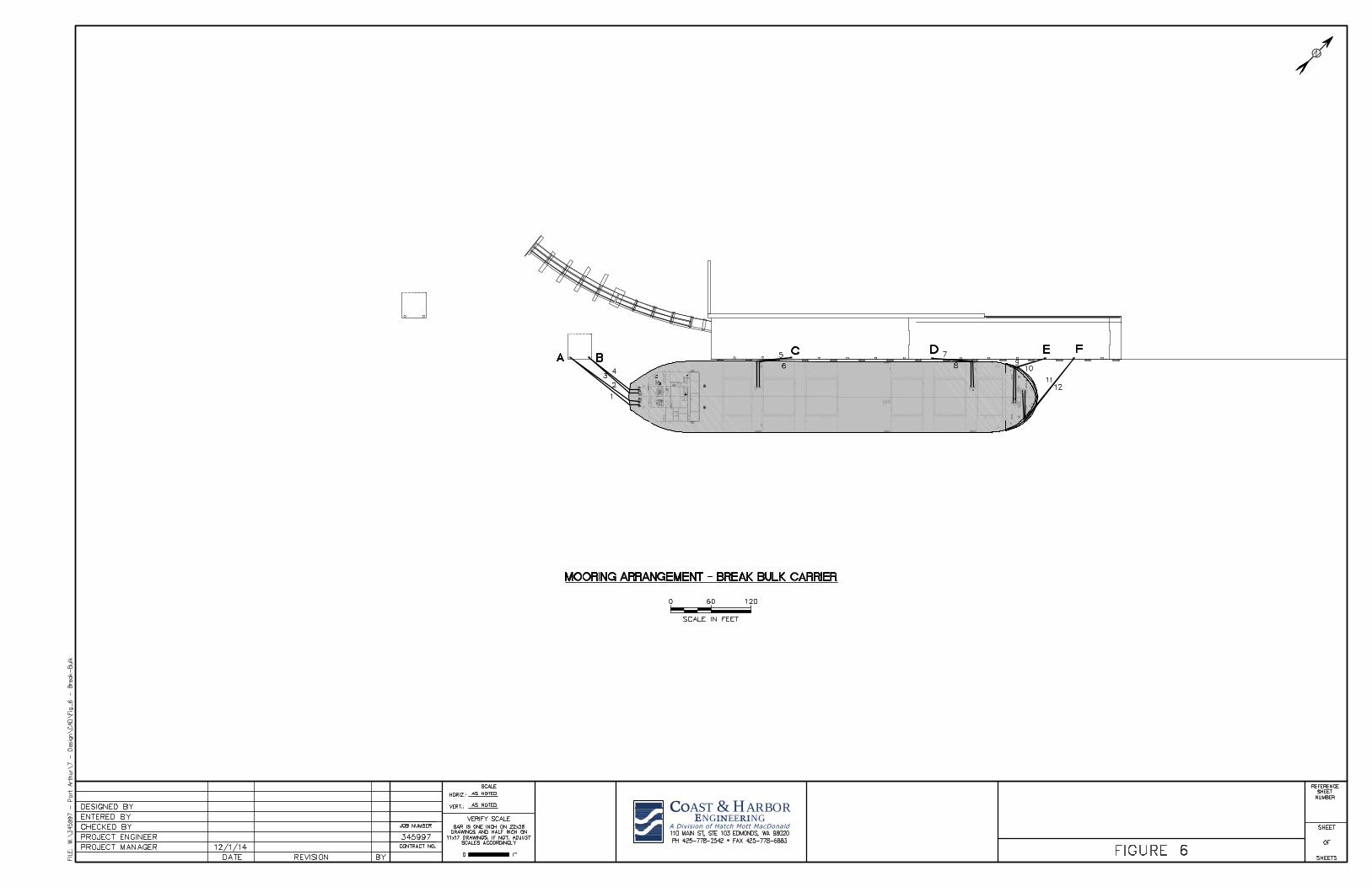
Figure 6. Break-bulk Carrier Mooring Arrangement, Proposed B6 Configuration ........................................... 8
Figure 7. Bulk Carrier Mooring Arrangement, Proposed B6 Configuration ..................................................... 9
Figure 8. Waterway Bathymetry in Hydrodynamic Modeling Domain for Future Configuration (left) and
Proposed B6 Configuration (right) ..................................................................................................... 11
Figure 9. Typical Vessel Hydrodynamic Results for Scenario 1, including distribution of Water Levels
(left) and Velocities (right) ................................................................................................................. 11
Figure 10. Hydrodynamic Force and Moment Definition Sketch .................................................................... 11
Figure 11. Comparison of Off-the-Dock Wind Loads and Passing Ship Loads .............................................. 14
Figure 12. Wind Limit Rose for Containership at Maximum Draft, Fully Loaded ......................................... 16

Technical Report Page ii Ship Hydrodynamics and Mooring Analysis January 8, 2015 Berth 6 Bulkhead Extension, Port of Port Arthur, TX
Figure 13. Wind Limit Rose for Ro/Ro Vessel at Ballast Draft ...................................................................... 16
Figure 14. Wind Limit Rose for Break-bulk Carrier at Ballast Draft .............................................................. 17
Figure 15. Wind Limit Rose for Bulk Carrier at Ballast Draft ........................................................................ 18
TABLES
Table ES1. Wind Mooring Limits by Vessel ..................................................................................................... v
Table 1. Design Vessel Particulars1 ................................................................................................................... 2
Table 2. Mooring Analysis Scenarios ................................................................................................................ 3
Table 3. Peak Loads and Yaw Moments .......................................................................................................... 12
Table 4. Wind Mooring Limits by Vessel ........................................................................................................ 18
Table 5. Summary of Dynamic Mooring Analysis Results for Containership Scenarios ................................ 19
Table 6. Summary of Dynamic Mooring Analysis Results for Ro/Ro Scenarios ............................................ 20
Table 7. Summary of Dynamic Mooring Analysis Results for Break-Bulk Carrier Scenarios ....................... 21
Table 8. Summary of Dynamic Mooring Analysis Results for Bulk Carrier Scenarios .................................. 21
Table 9. Summary of Minimum Fender Requirements ................................................................................... 25

Technical Report Page i Ship Hydrodynamics and Mooring Analysis January 8, 2015 Berth 6 Bulkhead Extension, Port of Port Arthur, TX
Ship Hydrodynamics and Mooring Analysis Berth 6 Bulkhead Extension Port of Port Arthur, TX
Executive Summary
Ship hydrodynamic modeling and mooring analysis were performed by Coast & Harbor
Engineering, a Division of Hatch Mott MacDonald (CHE) upon request from Lockwood,
Andrews and Newnam (LAN) to provide an assessment of vessel mooring and operational
conditions at the proposed Berth 6, Port of Port Arthur, Texas. The present analysis included
evaluation of mooring feasibility for four different berthed vessels ranging in length overall from
607 to 1,204 feet subject to forces and moments generated by passing tankers, as well as
environmental forces. The berthed vessels included a containership, Roll-On/Roll-Off (Ro/Ro)
vessel, a break-bulk carrier and a bulk carrier.
The analysis utilized CHE’s proprietary hydrodynamic modeling tools to develop passing vessel
forces. Static and dynamic mooring analysis simulations were performed using the OPTIMOOR
program. Mooring analysis results were evaluated based on criteria for mooring line loads
provided by Oil Companies International Marine Forum (OCIMF 1978) and criteria for berthed
vessel motions provided by Permanent International Association of Navigation Congresses
(PIANC 1995), both coordinated with LAN prior to the analysis.
CHE performed eight distinct passing vessel hydrodynamic modeling simulations to evaluate
forces and moments on the various berthed vessels generated by a 900-ft tanker passing at speeds
of 4 and 6 knots. Each hydrodynamic simulation was accompanied by a mooring analysis to
evaluate the corresponding loads on the mooring lines, fenders, bollards, and ship motions at
Berth 6. The passing ship hydrodynamic modeling simulations and dynamic mooring analysis
results suggest the following:
• Given conditions without passing vessels and with mild environmental conditions,
mooring of all four vessels appears feasible at the proposed berth. Feasibility of transit,
maneuvering and berthing of the larger vessels should be evaluated.
• The passing 900-ft tanker generates significant forces on all four berthed vessels even at
passing speed of 4 knots, with loads varying primarily based on berthed vessel size.
• Loads on the vessels when passed by the 900-ft tanker at 6 knots are similar in magnitude
to wind loads during strong wind events blowing off-the-dock.
• Forces and moments generated by inbound and outbound ships are similar.

Technical Report Page ii Ship Hydrodynamics and Mooring Analysis January 8, 2015 Berth 6 Bulkhead Extension, Port of Port Arthur, TX
• Passing ship speed is critical. Increases in surge loads from 4- to 6-knot passing speeds
range between factors of 2.7 and 2.9. Increases in sway loads from 4- to 6-knot passing
speeds range between factors of 2.3 and 2.7.
• Mooring configurations:
o In the Proposed B6 Configuration, the break-bulk and bulk carriers can be moored
either port-side-to or starboard-side-to.
o In the Future Configuration with a continuous extension of the wharf nearly to the
MLK Bridge, the bulk, break-bulk or container vessels could be moored either
port-side-to or starboard-side-to.
o The RoRo vessel will always be moored starboard-side-to due to the stern ramp
configuration for the assumed prototype vessel.
• Containership:
o Forces on the moored 1,204-ft containership, in particular surge forces, are too
large to prevent dangerous motions and potential mooring hazards given the
elastic nature of the synthetic mooring lines present on most containerships.
o While line forces are within limits for passing speed 4 knots, motions are well
outside limits advised by PIANC.
o At a passing speed of 6 knots, nearly all mooring line capacities are exceeded, 10
of the 12 mooring winches pay out line, and ship motions are large enough to
potentially result in damage to the ship, wharf and serious injury.
• Ro/Ro Vessel:
o Forces on the moored 942-ft Ro/Ro vessel, in particular surge forces, are too large
to prevent dangerous motions and potential mooring hazards given the elastic
nature of the synthetic mooring lines.
o Line forces are within limits for passing speed 4 knots; however, motions are well
outside limits advised by PIANC and potentially damaging if they were to occur
during loading/offloading operations or when the stern ramp is deployed.
o Two bollards on the existing Berth 5 were required to be utilized in the mooring;
therefore, the capacities of those bollards should be evaluated in comparison with
the bollard loads provided here.
o For a passing speed of 6 knots, roughly half of the mooring line capacities are
exceeded, winches pay out line, and ship motions are large enough to potentially
result in damage to the ship, wharf, and/or serious injury.
• Bulk Carrier:
o Forces on the moored 771-ft bulk carrier, while significantly lower than those on
the containership and Ro/Ro vessel, are still quite large relative to mooring line
capacities and can create dangerous motions.
o At a passing speed of 4 knots, mooring line forces and ship motions are within
advised limits.

Technical Report Page iii Ship Hydrodynamics and Mooring Analysis January 8, 2015 Berth 6 Bulkhead Extension, Port of Port Arthur, TX
o At a passing speed of 6 knots, almost half of the mooring line capacities are
exceeded, winches pay out line, and ship motions are large enough to result in
damage to the ship, wharf, and/or serious injury.
o Two bollards on the existing Berth 5 were required to be utilized in the mooring;
therefore the capacities of those bollards should be evaluated in comparison with
the bollard loads provided here.
• Break-Bulk Carrier:
o Forces on the moored 607-ft break-bulk carrier are significantly lower than those
imposed on the other berthed vessels.
o Line forces and ship motions are within advised limits for passing speeds of both
4 and 6 knots.
While currents were not included in the passing vessel simulations, for the purpose of providing
a general understanding of tidal/river current effects it can be roughly assumed that an opposing
current would effectively increase the passing vessel speed through the water and a following
current would effectively decrease the passing vessel speed through the water by an amount
similar to the current speed.
Static mooring analysis was also performed to evaluate mooring capability for each vessel under
strong wind conditions. Cursory review of data from NOAA CO OPS Station sn0701 at Port
Arthur indicates that in general, tidal currents in the channel have speeds less than 1-2 knots
most of the time and are not expected to be a significant factor in the environmental loads.
Loads on the berthed vessels from winds of various magnitudes are shown below in Figure ES-1.
In general, wind loads on the containership when fully loaded at maximum draft are the largest,
followed by the empty Ro/Ro, which has its maximum windage area when empty since it is fully
enclosed. Beam-on wind loads on the fully loaded containership are similar to the peak sway
load from the passing tanker at 6 knots (containership at maximum draft) when wind speeds
reach approximately 25 knots. The peak sway load on the Ro/Ro vessel for passing tanker at 6
knots (Ro/Ro at maximum draft) is greater than wind loads until wind speeds reach
approximately 27 knots.
Wind loads on the break-bulk and bulk carriers are significantly lower due to their relatively
small windage areas, even at ballast draft. Beam-on wind loads on the break-bulk carrier at
ballast draft are smaller than the peak surge load from the passing tanker at 6 knots (break-bulk
carrier at maximum draft) until wind speeds reach approximately 47 knots. Beam-on wind loads
on the bulk carrier at ballast draft are smaller than the peak loads from the passing tanker at 6
knots (bulk carrier at maximum draft) until wind speeds are greater than 52 knots.
The analysis of wind loads on the moored vessels indicates that the passing ship forces and
moments are a significant factor in mooring safety at the terminal, and can be greater in
magnitude than extreme wind forces. Wind limits were developed for each of the vessels to
determine operational limits governed by ship motions, and mooring limits governed by mooring
line forces. Bollard and fender forces do not govern the mooring limits in the results.

Technical Report Page iv Ship Hydrodynamics and Mooring Analysis January 8, 2015 Berth 6 Bulkhead Extension, Port of Port Arthur, TX
Figure ES-1. Comparison of Off-the-Dock Wind Loads and Passing Ship Loads

Technical Report Page v Ship Hydrodynamics and Mooring Analysis January 8, 2015 Berth 6 Bulkhead Extension, Port of Port Arthur, TX
Wind limits for both operations (per limits advised by PIANC) and mooring (per limits advised
by OCIMF) are provided in Table ES1 below. Relatively low wind limits for the Ro/Ro vessel
operations are a function of its mooring system and strict limits by PIANC and not the berth
configuration.
Table ES1. Wind Mooring Limits by Vessel
Ship Operational Wind Limit
[kts] Mooring Wind Limit
[kts]
Containership 20 27
Ro/Ro Vessel 10 28
Break-bulk Carrier 51 63
Bulk Carrier 56 42
Notes:
1. Wind speeds are 30-second averages at 10-meter elevation.
2. Operational and mooring limits may be governed by other practical concerns arising during operations
in strong wind conditions.
The results of the analysis and conclusions above are specific to the vessels, waterway
configuration, mooring equipment and mooring arrangement assumptions, and terminal
configuration used in the analysis.

Technical Report Page 1 Ship Hydrodynamics and Mooring Analysis January 8, 2015 Berth 6 Bulkhead Extension, Port of Port Arthur, TX
Ship Hydrodynamics and Mooring Analysis Berth 6 Bulkhead Extension Port of Port Arthur, TX
1. Introduction
Ship hydrodynamic modeling and mooring analysis were performed by Coast & Harbor
Engineering, a Division of Hatch Mott MacDonald (CHE) upon request from Lockwood,
Andrews and Newnam (LAN) to provide an assessment of vessel mooring and operational
conditions at the proposed Berth 6, Port of Port Arthur, Texas. The analysis was performed to
evaluate feasibility of mooring a range of berthed vessel sizes and types, and to provide
loading in mooring system components to be used by LAN during design.
2. Terminal Configuration
The dimensions and layout of the proposed terminal, locations of the bollards and fenders,
along with their capacities, were obtained from a data request memorandum (Coast & Harbor
Engineering 2014), which is provided as Appendix A. Additional design details were
coordinated via teleconferences and overall structural plan and typical sections, dated
August 18, 2014 received via e-mail on September 12, 2014, and shown in Figure 1.
Figure 1. Original Berth 6 Design Plan Dated September 12, 2014

Technical Report Page 2 Ship Hydrodynamics and Mooring Analysis January 8, 2015 Berth 6 Bulkhead Extension, Port of Port Arthur, TX
3. Design Vessels
Design vessel data were provided by LAN, including the vessel types and particulars. Table 1
provides the particulars of each design berthed and passing vessel, as well as mooring line
types and capacities, all coordinated with LAN prior to the analysis. The winch brakes on
each vessel were set to pay out at approximately 60% of Minimum Breaking Load (MBL)
during the dynamic simulations. Each vessel was assumed to utilize a 12-line arrangement
with pre-tension set to 10% of MBL. The winch and fairlead layouts were approximated
from prototype vessels similar to the design vessels, which were coordinated with LAN prior
to the analysis. The containership prototype vessel was COSCO Long Beach, the bulk and
break-bulk carrier prototype was CSL Acadian, and the RoRo prototype was Tonsberg.
Above-deck windage areas were scaled based on the differences in length and beam between
prototype and design vessels.
Table 1. Design Vessel Particulars
1
Particular 7,600 TEU
Containership Ro/Ro Vessel
Break-bulk
Carrier Bulk Carrier
Passing
Suezmax
Tanker
Length Overall [feet] 1,204 942 607 771 900
Breadth [feet] 138 106 106.0 141 164
Moulded Depth [feet]
66.4 109.0 66.3 66.3 -------
Maximum Draft [feet] 43.6 40.7 39.4 40 402
Normal Ballast Draft [feet]
28.0 24.0* 21.3* 21.3* -------
Mooring Line Type Nylon 8-Strand PP*3 PP* PP* PP*
Minimum Breaking Load [MBL, kips]
227 171 191 191 -------
Mooring Line Circumference [inch]
8.7 9.3 9.9 9.9 -------
Side Above-Deck Windage Area [feet]
205,0004 15,200
5 5,800 7,350 -------
End-On Above-Deck Windage Area [feet]
24,0004 2,000
5 4,500 6,000 -------
Notes:
1. * indicates estimated values
2. Maximum allowed in channel per Sabine Pilots May 2014.
3. PP = polypropylene.
4. Fully loaded containership windage area estimated from photographs.
5. Upper deck level used in windage area definition.
4. Analysis Scenarios
Dynamic mooring analysis was conducted to evaluate mooring safety for passing vessel
forces at maximum allowable drafts. Static simulations were performed to evaluate wind
loads on the vessels and general wind mooring capability at normal ballast drafts. Dynamic
simulations assumed Mean Lower Low Water (MLLW, +0.22 feet NAVD) tidal elevation
and static simulations assumed Mean Higher High Water (MHHW, +1.27 feet NAVD), both
of which are conservative. All information regarding tidal and fixed plane datum elevations
were provided by LAN. Dynamic passing vessel simulations neglected winds and currents.

Technical Report Page 3 Ship Hydrodynamics and Mooring Analysis January 8, 2015 Berth 6 Bulkhead Extension, Port of Port Arthur, TX
Static simulations included only winds. Inbound and outbound tankers were found to
generate very similar forces; therefore all simulations were performed with inbound tankers.
Two berth configurations were evaluated:
1. Proposed B6 Configuration: The proposed configuration consists of the Berth 6
Bulkhead Extension as presently designed.
2. Future Configuration: The “future” configuration is a lengthened, continuous wharf
required for mooring the containership which is too large to be moored in the proposed
Berth 6 configuration dredging scheme.
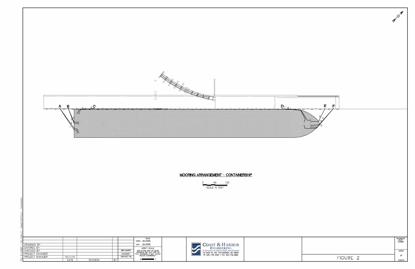
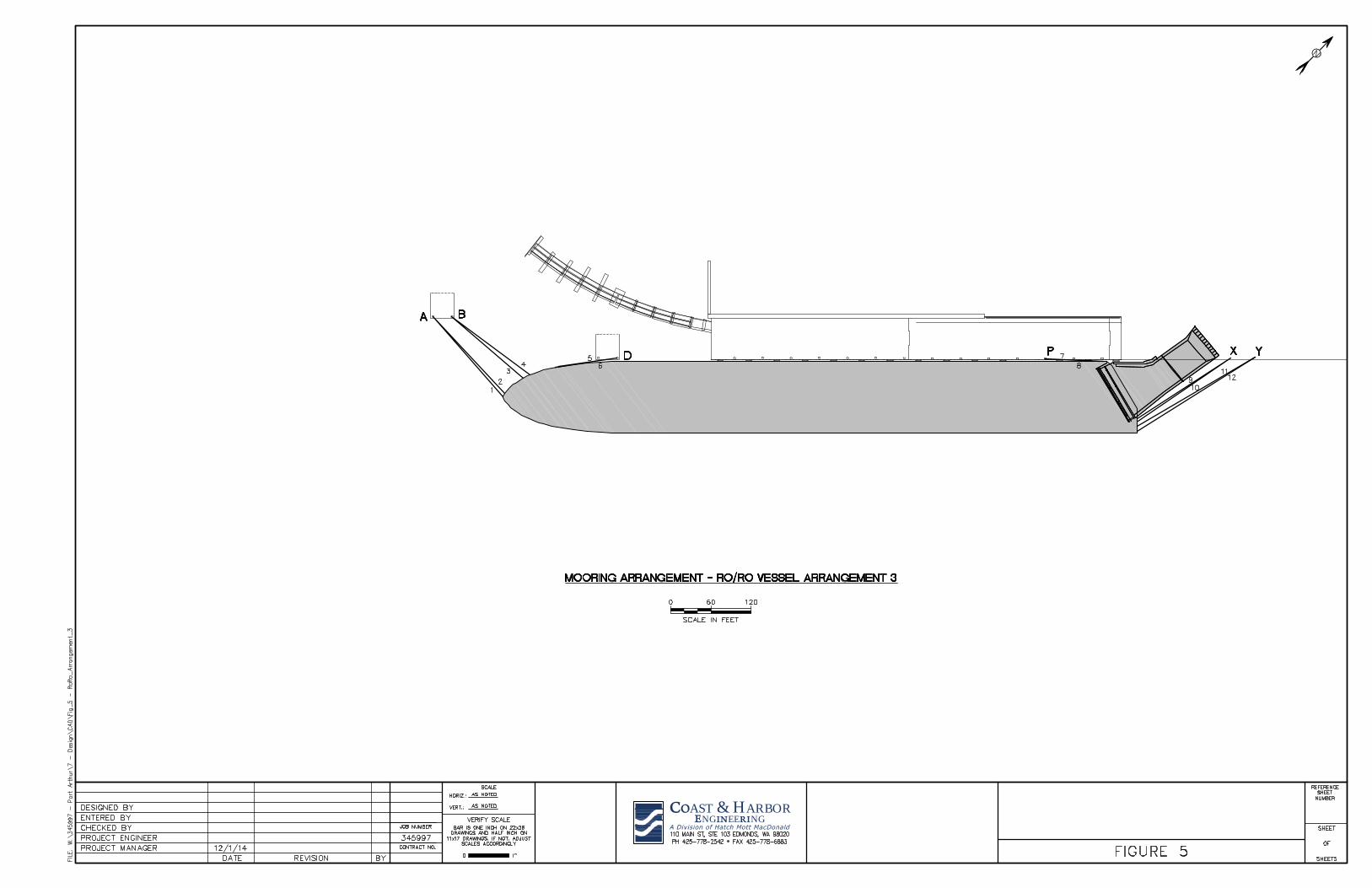
Table 2 lists the details of the scenarios evaluated in the mooring analysis. Figure 2 shows
the assumed mooring arrangement for the containership at the Future wharf. Figures 3-5
show three different assumed mooring arrangements at the Proposed B6 wharf for the Ro/Ro
vessel. Figures 6 and 7 show the assumed mooring arrangement for the break-bulk and bulk
carriers, respectively, at the Proposed B6 wharf.
Table 2. Mooring Analysis Scenarios
Scenario Berth Layout Berthed Ship Passing Speed [kts]
1 Future 7,600 TEU Containership 4
2 Proposed Ro/Ro Vessel 4
3 Proposed Break-bulk Carrier 4
4 Proposed Bulk Carrier 4
5 Future 7,600 TEU Containership 6
6 Proposed Ro/Ro Vessel 6
7 Proposed Break-bulk Carrier 6
8 Proposed Bulk Carrier 6
Notes:
1. All scenarios have 900-ft tanker passing inbound along channel centerline. 2. No winds or currents.
AST & H A R BORNG EE NG

AST & H A R BORNG EE NG

AST & H A R BORNG EE NG
AST & H A R BORNG EE NG
AST & H A R BORNG EE NG

AST & H A R BORNG EE NG

Technical Report Page 10 Ship Hydrodynamics and Mooring Analysis January 8, 2015 Berth 6 Bulkhead Extension, Port of Port Arthur, TX
While currents were not included in the passing vessel simulations, for the purpose of
providing a general understanding of tidal/river current effects it can be roughly assumed that
an opposing current would effectively increase the passing vessel speed through the water
and a following current would effectively decrease the passing vessel speed through the
water by an amount similar to the current speed. Cursory review of data from NOAA
CO-OPS Station sn0701 at Port Arthur indicates that in general, tidal currents in the channel
have speeds less than 1-2 knots most of the time. These current data are readily available
online if further analysis of tidal current effects is desired.
5. Passing Vessel Hydrodynamic Modeling
Passing vessel hydrodynamic forces were calculated using the Vessel Hydrodynamics
Longwave Unsteady (VH-LU) model (Fenical et al., 2006). The VH-LU model predicts
water level and velocity fluctuations surrounding the passing ships and the resulting
hydrodynamic loads on the berthed vessels. The results of the hydrodynamic analysis include
time histories of surge force, sway force, and yaw moment for each of the 8 hydrodynamic
modeling scenarios.
The bathymetry used in the VH-LU model was single-beam hydrographic survey data
provided by LAN, design berth cross-sections, and channel boundary information from the
U.S. Army Corps of Engineers. Since the single-beam data did not provide complete
waterway coverage, some idealization was performed to complete the modeling domain. For
each simulation, the assumed tidal elevation was equal to MLLW (+0.22 feet NAVD), which
represents a conservative low-water condition. No waves, winds, or currents were included.
Figure 8 shows the bathymetry within the hydrodynamic modeling domain for the Future
(left) and Proposed B6 (right) Configurations. Figure 9 shows an example vessel
hydrodynamic modeling result with the 900-ft tanker passing the containership at 4 knots
inbound along the channel centerline (Scenario 1) including the distribution of water levels
(left) and velocities (right). Figure 10 provides a force/moment definition sketch to be used
for interpretation of passing vessel loads and moments. Surge loads are defined as positive to
stern, sway loads are defined as positive to port, and yaw moments are positive
counter-clockwise looking down.

Technical Report Page 11 Ship Hydrodynamics and Mooring Analysis January 8, 2015 Berth 6 Bulkhead Extension, Port of Port Arthur, TX
Figure 8. Waterway Bathymetry in Hydrodynamic Modeling Domain for Future Configuration (left) and Proposed B6 Configuration (right)
Figure 9. Typical Vessel Hydrodynamic Results for Scenario 1, including distribution of Water Levels (left) and Velocities (right)
Figure 10. Hydrodynamic Force and Moment Definition Sketch
Technical Report Page 12 Ship Hydrodynamics and Mooring Analysis January 8, 2015 Berth 6 Bulkhead Extension, Port of Port Arthur, TX
Appendix B shows the time histories of loads and moments for all 8 hydrodynamic modeling
scenarios, including an additional Scenario 2 condition with the Ro/Ro shifted along the
dock. In general, the surge and sway loads are similar in magnitude. For the containership
and Ro/Ro vessel, sway loads are larger than surge loads, whereas for the break-bulk carrier
and bulk carrier, the surge loads are larger. In all cases however, the surge loads are much
more problematic since generally there are only 2 mooring lines resisting the surge load in
either direction, whereas 8 lines participate in resisting the sway load.
As in all confined channels, passing ship speed strongly affects both surge and sway loads.
Peak surge loads are between 2.7 and 2.9 times larger at passing speed 6 knots than at 4
knots. Peak sway loads are between 2.3 and 2.7 times larger at passing speed 6 knots than at
4 knots. Peak minimum and maximum loads and moments are listed in Table 3.
Table 3. Peak Loads and Yaw Moments
Scenario Aft Surge
[kips]
Fwd Surge
[kips]
Port Sway
[kips]
Stbd Sway
[kips]
Max Yaw
Moment [kip-ft]
Min Yaw
Moment [kip-ft]
1 154 -141 141 -294 45,000 -49,200
2 91 -100 126 -67 14,400 -15,800
3 80 -74 46 -70 5,900 -6,000
4 130 -124 85 -149 15,300 -15,500
5 451 -345 384 -681 119,000 -129,000
6 225 -266 334 -171 38,000 -39,000
7 226 -191 120 -176 14,400 -15,100
8 382 -315 213 -373 37,200 -36,400
Notes: 1. Loads on Ro/Ro vessel reported here are for ship position shown in mooring arrangement #1.
6. Mooring Analysis
6.1. Methodology
Both the dynamic and static mooring analyses were performed using the OPTIMOOR
6.2.9 package with seakeeping capabilities. Inputs to OPTIMOOR included all
relevant terminal data and the vessel characteristics detailed in Section 3 and Table 1.
For all berthed vessels, pre-tensioning was assumed to be approximately 10% of
Minimum Breaking Load (MBL), with winch brakes set to pay out line at
approximately 60% of Minimum Breaking Load (MBL).
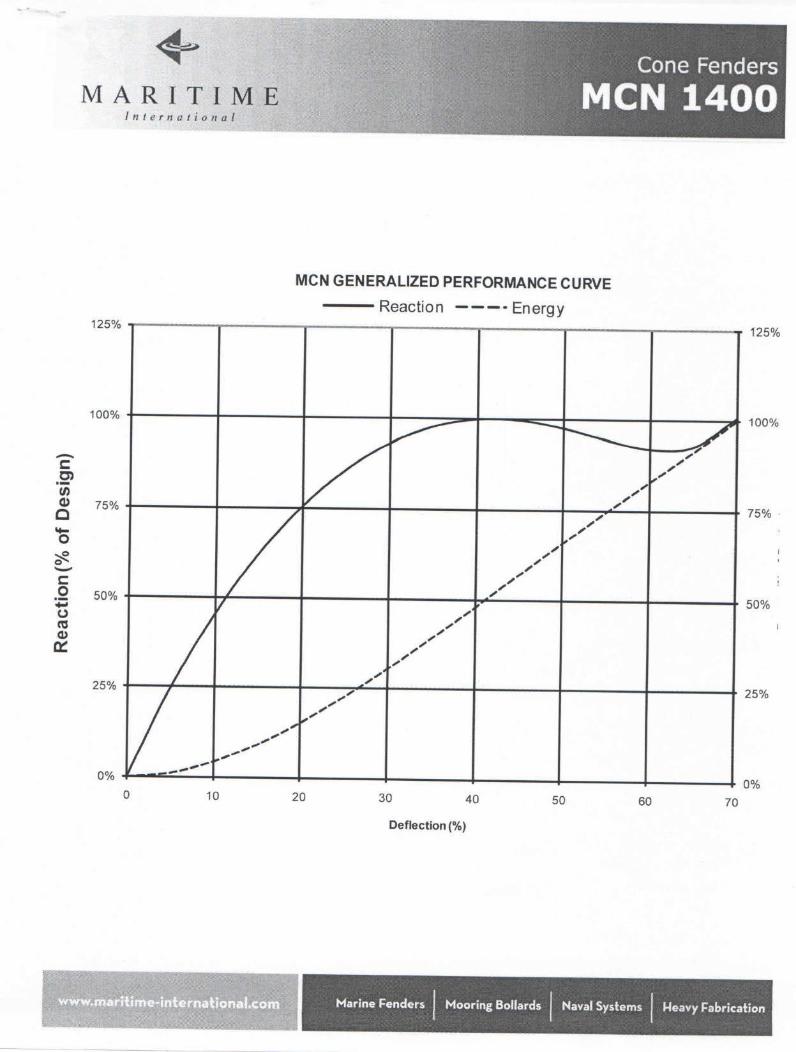
For the purposes of the analysis, the largest fender that was required for any of the
four design vessels was used, and assumed to be model MCN 1400 Grade G3.4 cone
fenders with maximum reaction 475 kips at 70% compression (Maritime International
2014). A detailed berthing analysis resulting in minimum fender performance (energy
absorption) recommendations for each of the berthed vessels is included in
Appendix D.
The containership, bulk carrier and break-bulk carrier were all simulated with a single
mooring arrangement, as the relative mooring arrangement is not significantly altered

Technical Report Page 13 Ship Hydrodynamics and Mooring Analysis January 8, 2015 Berth 6 Bulkhead Extension, Port of Port Arthur, TX
when these ships berth in different locations along the wharf. The RoRo ship was
simulated with 3 different mooring arrangements due to more complex mooring
equipment and flat-side hull limitations presented by the vessel. Mooring and
operational safety were evaluated according to the following criteria:
• Ship motions (PIANC 1995):
o Containership = +/- 3.3ft surge, 3.9ft sway (50% efficiency)
o Ro/Ro Vessel = +/- 2.0ft surge, 2.0ft sway
o Break-Bulk Carrier = +/- 3.3ft surge, 3.3ft sway
o Bulk Carrier = +/- 3.3ft surge, 3.3ft sway
• Synthetic mooring line forces (OCIMF): less than 50% of MBL
• Winch brake limits for initiation of payout (OCIMF): 60% of MBL
• Fender loads and compression: within rated capacities
Static mooring analyses were performed to evaluate mooring capability in strong
winds. The water level during each static mooring scenario was equal to MHHW
(+1.27 feet NAVD), with currents, waves, and passing vessel forces assumed to be
negligible, and all vessels at normal ballast draft except the containership, which was
evaluated at maximum draft since it would be fully loaded. No analysis of extreme
wind speeds or return periods was performed. All wind speeds noted here are 30-
second averages at 10-meter elevation.
The dynamic mooring analyses listed in Table 2 were performed utilizing the passing
vessel hydrodynamic forces and moments described in Section 5, Table 3, and
Appendix B in order to evaluate loads on mooring structures, loads on the mooring
lines, the safety of the proposed mooring systems, and potential impacts to terminal
operations. For each dynamic simulation, the assumed tidal elevation in OPTIMOOR
was equal to MLLW (+0.22 feet NAVD). Winds, wind-generated waves, and tidal
currents were neglected in the dynamic passing vessel mooring analysis.
6.2. Wind Loads
Winds were not explicitly included in the passing ship dynamic mooring analysis
simulations. In general the wind loads on the ships are lower than passing vessel
forces during most conditions, in particular for the smaller vessels. In order to provide
an indication of the relative load magnitudes during wind events, wind loads were
calculated within OPTIMOOR for all four vessels with winds blowing off the dock at
speeds between 15 and 52 knots. The 52-knot wind speed was provided by LAN and
described as the wind speed at which vessels would depart the dock.
Figure 11 shows a comparison of the off-the-dock wind loads and peak surge and
sway load magnitudes for each of the four vessels, including the containership (top),
Ro/Ro vessel (middle top), break-bulk carrier (middle bottom) and bulk carrier
(bottom). All wind speeds are 30-second duration at 10-meter elevation. The surge
load shown is the larger of the two peak surge loads, and the peak sway loads are
those directed towards the passing vessel.

Technical Report Page 14 Ship Hydrodynamics and Mooring Analysis January 8, 2015 Berth 6 Bulkhead Extension, Port of Port Arthur, TX
Figure 11. Comparison of Off-the-Dock Wind Loads and Passing Ship Loads

Technical Report Page 15 Ship Hydrodynamics and Mooring Analysis January 8, 2015 Berth 6 Bulkhead Extension, Port of Port Arthur, TX
In general, wind loads on the containership when fully loaded at maximum draft are
the largest, followed by the empty Ro/Ro, which has its maximum windage area
when empty since it is fully enclosed. Beam-on wind loads on the fully loaded
containership are similar to the peak sway load from the passing tanker at 6 knots
(containership at maximum draft) when wind speeds reach approximately 25 knots.
The peak sway load on the Ro/Ro vessel for passing tanker at 6 knots (Ro/Ro at
maximum draft) is greater than wind loads until wind speeds reach approximately
27 knots.
Wind loads on the break-bulk and bulk carriers are significantly lower due to their
relatively small windage areas, even at ballast draft. Beam-on wind loads on the
break-bulk carrier at ballast draft are smaller than the peak surge load from the
passing tanker at 6 knots (break-bulk carrier at maximum draft) until wind speeds
reach approximately 47 knots. Beam-on wind loads on the bulk carrier at ballast draft
are smaller than the peak loads from the passing tanker at 6 knots (bulk carrier at
maximum draft) until wind speeds are greater than 52 knots.
The analysis of wind loads on the moored vessels indicates that the passing ship
forces and moments are a significant factor in mooring safety at the terminal, and can
be greater in magnitude than extreme wind forces.
6.3. Static Mooring Analysis Results - Winds
Mooring capability evaluation for strong wind conditions was performed through
development of wind limit roses. Each of the wind limit roses provides an overview
of the wind speed and direction combinations that induce violation of a safe mooring
criterion, such as motions, or forces in mooring lines, bollards and fenders.
Figure 12 shows a wind mooring limit rose for the containership fully laden, with
maximum windage area. Analysis indicates that allowable motions for 50%
operational efficiency are violated at wind speeds greater than 20 knots blowing off
the dock. Bollard and mooring line limits are violated at wind speeds greater than
roughly 27 knots blowing off the dock.
Figure 13 shows a wind mooring limit rose for the Ro/Ro ship at ballast draft, with
maximum windage area. Analysis indicates that allowable sway motions are violated
at very low wind speeds due to the two-foot sway limit. The motion limit is exceeded
at approximately 10 knots blowing off the dock, primarily due to the long stern
mooring lines which provide little breasting capacity due to the presence of the stern
ramp. Mooring line limits are violated at wind speeds greater than roughly 28 knots,
and bollard limits are violated at approximately 45 knots.

Technical Report Page 16 Ship Hydrodynamics and Mooring Analysis January 8, 2015 Berth 6 Bulkhead Extension, Port of Port Arthur, TX
Figure 12. Wind Limit Rose for Containership at Maximum Draft, Fully Loaded
Figure 13. Wind Limit Rose for Ro/Ro Vessel at Ballast Draft

Technical Report Page 17 Ship Hydrodynamics and Mooring Analysis January 8, 2015 Berth 6 Bulkhead Extension, Port of Port Arthur, TX
Figure 14 shows a wind mooring limit rose for the break-bulk carrier at ballast draft,
with maximum windage area. Analysis indicates that allowable sway motions are not
violated until relatively high wind speeds. The motion limit is exceeded at
approximately 51 knots blowing off the dock. Mooring line limits are violated at wind
speeds greater than roughly 63 knots, and no bollard limits were reached in the
analysis.
Figure 15 shows a wind mooring limit rose for the bulk carrier at ballast draft, with
maximum windage area. Analysis indicates that allowable sway motions are not
violated until relatively high wind speeds. The motion limit is exceeded at
approximately 42 knots blowing off the dock. Mooring line limits are violated at wind
speeds greater than roughly 56 knots, and bollard limits are violated only at wind
speeds greater than 90 knots.
The wind operational and mooring wind limits for each vessel are summarized in
Table 4.
Figure 14. Wind Limit Rose for Break-bulk Carrier at Ballast Draft

Technical Report Page 18 Ship Hydrodynamics and Mooring Analysis January 8, 2015 Berth 6 Bulkhead Extension, Port of Port Arthur, TX
Figure 15. Wind Limit Rose for Bulk Carrier at Ballast Draft
Table 4. Wind Mooring Limits by Vessel
Ship Operational Wind Limit [kts] Mooring Wind Limit [kts]
Containership 20 27
Ro/Ro Vessel 10 28
Break-bulk Carrier 51 63
Bulk Carrier 56 42
Notes:
1. Wind speeds are 30-second averages at 10-meter elevation.
2. No analysis of wind data or return periods of these wind speeds was performed.
6.4. Dynamic Mooring Analysis Results – Passing Vessels
The results of the dynamic mooring analysis are presented in Appendix C and
Table 4. Appendix C provides mooring analysis results figures including peak line
forces, manifold motions, peak fender forces, and peak bollard forces that occurred at
any time in each dynamic simulation. Tables 5-8 show a summary of mooring
analysis results with greater detail including peak forces in individual mooring lines,
peak ship motions, and peak forces in bollards and fenders.

Technical Report Page 19 Ship Hydrodynamics and Mooring Analysis January 8, 2015 Berth 6 Bulkhead Extension, Port of Port Arthur, TX
Table 5. Summary of Dynamic Mooring Analysis Results for Containership Scenarios
Allowed 4 knot 6 knot
Max. Surge (feet) 3.3 8.07 30.0
Max. Sway (feet) 3.9 2.83 11.8
Max. Yaw (deg.) N/A 0.38 1.32
Max. Total Force on Bollard A (kips) 275 104.3 273.7
Max. Total Force on Bollard B (kips) 275 111.8 274.0
Max. Total Force on Bollard C (kips) 275 110.2 274.0
Max. Total Force on Bollard D (kips) 275 178.1 274.0
Max. Total Force on Bollard E (kips) 275 122.9 273.5
Max. Total Force on Bollard F (kips) 275 82.0 214.2
Max. Reaction at Fender cc (kips) 475 209.7 299.9
Max. Reaction at Fender dd (kips) 475 153.3 472.9
Max. Reaction at Fender ee (kips) 475 122.4 459.0
Max. Reaction at Fender ff (kips) 475 92.7 382.8
Max. Reaction at Fender gg (kips) 475 61.8 328.3
Max. Reaction at Fender hh (kips) 475 56.8 254.2
Max. Reaction at Fender ii (kips) 475 55.0 180.2
Max. Reaction at Fender jj (kips) 475 56.6 90.3
Max. Reaction at Fender kk (kips) 475 58.3 47.0
Max. Reaction at Fender ll (kips) 475 59.9 36.7
Max. Reaction at Fender mm (kips) 475 61.6 32.8
Max. Reaction at Fender nn (kips) 475 63.2 37.9
Max. Reaction at Fender oo (kips) 475 68.4 50.8
Max. Reaction at Fender pp (kips) 475 76.0 85.6
Max. Reaction at Fender qq (kips) 475 84.6 139.9
Max. Reaction at Fender rr (kips) 475 93.2 175.7
Max. Reaction at Fender ss (kips) 475 101.9 211.6
Max. Reaction at Fender tt (kips) 475 110.5 244.8
Max. Reaction at Fender uu (kips) 475 119.2 278
Max. Reaction at Fender vv (kips) 475 123.1 311.2
Max. Reaction at Fender ww (kips) 475 127.0 344.3
Max. Reaction at Fender xx (kips) 475 130.9 381.1
Max. Load on Line 1 (kips) 113.5 46.2 137.0
Max. Load on Line 2 (kips) 113.5 58.3 137.0
Max. Load on Line 3 (kips) 113.5 55.2 137.0
Max. Load on Line 4 (kips) 113.5 56.6 137.0
Max. Load on Line 5 (kips) 113.5 54.0 137.0
Max. Load on Line 6 (kips) 113.5 56.2 137.0
Max. Load on Line 7 (kips) 113.5 93.8 137.0
Max. Load on Line 8 (kips) 113.5 84.3 137.0
Max. Load on Line 9 (kips) 113.5 56.4 137.0
Max. Load on Line 10 (kips) 113.5 67.4 137.0
Max. Load on Line 11 (kips) 113.5 41.4 109.5
Max. Load on Line 12 (kips) 113.5 40.6 104.8
Notes:
1. Bold red values indicate motions or loads outside advised limits.

Technical Report Page 20 Ship Hydrodynamics and Mooring Analysis January 8, 2015 Berth 6 Bulkhead Extension, Port of Port Arthur, TX
Table 6. Summary of Dynamic Mooring Analysis Results for Ro/Ro Scenarios
Allowed 4knot
(Original Design)
4 knot (ship shifted)
4 knot (ship and bollards
shifted)
6 knot (Original Design)
6 knot (ship shifted)
6 knot (ship and bollards
shifted)
Max. Surge (feet) 2.0 4.9 3.1 4.1 30.5 10.9 18.7
Max. Sway (feet) 2.0 5.5 7.6 6.3 12.3 17.3 15.5
Max. Yaw (deg.) 0.9 0.7 0.9 3.8 1.5 2.4
Max. Total Force on Bollard A (kips) 275 56.3 58.9 57.0 117.3 169.9 165.9
Max. Total Force on Bollard B (kips) 275 63.3 63.1 59.7 190.9 175.1 204.3
Max. Total Force on Bollard C (kips) 275 48.9 ------- ------- 186.6 ------- -------
Max. Total Force on Bollard D (kips) 275 ------- 80.0 59.9 ------- 206.1 197.2
Max. Total Force on Bollard N (kips) 275 167.6 ------- ------- 206.0 ------- -------
Max. Total Force on Bollard P (kips) 275 ------- 124.1 152.9 ------- 206.041 206.0
Max. Total Force on Bollard V (kips) Unknown 55.4 ------- ------- 115.8 ------- -------
Max. Total Force on Bollard W (kips) Unknown 44.7 ------- ------- 89.1 ------- -------
Max. Total Force on Bollard X (kips) Unknown ------- 76.5 68.9 ------- 205.9 205.4
Max. Total Force on Bollard Y (kips) Unknown ------- 60.7 54.9 ------- 163.8 155.5
Max. Reaction at Fender bb (kips) 475 365.4 387.9 346.3 596.7 509.7 410.2
Max. Reaction at Fender cc (kips) 475 281.8 323.9 224.8 473.0 471.2 632.4
Max. Reaction at Fender dd (kips) 475 192.4 235.2 123.5 76.6 474.1 473.9
Max. Reaction at Fender ee (kips) 475 134.1 160.7 92.4 62.7 447.8 446.7
Max. Reaction at Fender ff (kips) 475 59.6 137.7 56.1 58.9 344.0 29.2
Max. Reaction at Fender gg (kips) 475 32.4 112.3 20.9 55.2 142.7 28.4
Max. Reaction at Fender hh (kips) 475 29.6 70.5 13.2 90.1 125.6 27.6
Max. Reaction at Fender ii (kips) 475 30.2 71.6 12.8 169.0 125.6 26.9
Max. Reaction at Fender jj (kips) 475 30.9 75.1 13.9 230.4 125.6 26.4
Max. Reaction at Fender kk (kips) 475 31.6 80.3 32.3 288.6 126.0 30.4
Max. Reaction at Fender ll (kips) 475 40.2 85.5 106.2 346.8 161.7 190.1
Max. Reaction at Fender mm (kips) 475 56.2 120.3 146.6 383.8 208.7 307.4
Max. Reaction at Fender nn (kips) 475 ------- 176.4 185.4 ------- 252.4 392.5
Max. Reaction at Fender oo (kips) 475 ------- 232.5 225 ------- 295.9 445.4
Max. Load on Line 1 (kips) 85.5 27.8 29.6 28.9 59.4 86.0 83.4
Max. Load on Line 2 (kips) 85.5 28.5 29.3 28.7 58.0 83.9 82.5
Max. Load on Line 3 (kips) 85.5 31.6 31.6 30.2 88.3 87.6 101.6
Max. Load on Line 4 (kips) 85.5 31.8 31.6 29.6 103.0 87.6 103.0
Max. Load on Line 5 (kips) 85.5 24.2 39.3 29.1 91.6 103.0 96.6
Max. Load on Line 6 (kips) 85.5 24.7 40.8 29.9 95.0 103.0 100.5
Max. Load on Line 7 (kips) 85.5 86.0 63.3 77.9 103.0 103.0 103.0
Max. Load on Line 8 (kips) 85.5 82.7 60.8 75.0 103.0 103.0 103.0
Max. Load on Line 9 (kips) 85.5 26.8 37.4 33.5 56.2 103.0 102.4
Max. Load on Line 10 (kips) 85.5 28.6 39.1 35.4 59.6 103.0 103.0
Max. Load on Line 11 (kips) 85.5 21.4 29.3 26.3 42.9 79.3 74.8
Max. Load on Line 12 (kips) 85.5 23.4 31.3 28.5 46.6 84.5 80.7
Notes:
1. Bold red values indicate motions or loads outside advised limits.

Technical Report Page 21 Ship Hydrodynamics and Mooring Analysis January 8, 2015 Berth 6 Bulkhead Extension, Port of Port Arthur, TX
Table 7. Summary of Dynamic Mooring Analysis Results for Break-Bulk Carrier Scenarios
Allowed 4 knot 6 knot
Max. Surge (feet) 3.3 0.7 2.2
Max. Sway (feet) 3.3 0.2 3.7
Max. Yaw (deg.) N/A 0.1 0.7
Max. Total Force on Bollard A (kips) 275.0 50.5 113.0
Max. Total Force on Bollard B (kips) 275.0 53.8 139.6
Max. Total Force on Bollard C (kips) 275.0 59.0 118.8
Max. Total Force on Bollard D (kips) 275.0 63.3 111.9
Max. Total Force on Bollard E (kips) 275.0 52.8 94.6
Max. Total Force on Bollard F (kips) 275.0 44.4 157.9
Max. Reaction at Fender aa (kips) 475.0 68.3 317.6
Max. Reaction at Fender bb (kips) 475.0 50.4 273.6
Max. Reaction at Fender cc (kips) 475.0 42.2 229.7
Max. Reaction at Fender dd (kips) 475.0 36.5 187.5
Max. Reaction at Fender ee (kips) 475.0 37.2 149.8
Max. Reaction at Fender ff (kips) 475.0 37.9 110.4
Max. Reaction at Fender gg (kips) 475.0 38.6 119.5
Max. Reaction at Fender hh (kips) 475.0 39.7 153.1
Max. Load on Line 1 (kips) 95.5 25.1 56.6
Max. Load on Line 2 (kips) 95.5 25.4 56.4
Max. Load on Line 3 (kips) 95.5 26.6 69.8
Max. Load on Line 4 (kips) 95.5 27.3 69.8
Max. Load on Line 5 (kips) 95.5 29.3 58.5
Max. Load on Line 6 (kips) 95.5 29.7 60.2
Max. Load on Line 7 (kips) 95.5 32.0 57.1
Max. Load on Line 8 (kips) 95.5 31.4 54.7
Max. Load on Line 9 (kips) 95.5 26.3 46.9
Max. Load on Line 10 (kips) 95.5 26.5 47.7
Max. Load on Line 11 (kips) 95.5 22.3 82.2
Max. Load on Line 12 (kips) 95.5 22.1 75.7
Notes:
1. Bold red values indicate motions or loads outside advised limits.
Table 8. Summary of Dynamic Mooring Analysis Results for Bulk Carrier Scenarios
Allowed 4 knot 6 knot
Max. Surge (feet) 3.3 1.7 5.2
Max. Sway (feet) 3.3 2.1 8.9
Max. Yaw (deg.) N/A 0.3 1.1
Max. Total Force on Bollard A (kips) 275.0 65.4 134.3
Max. Total Force on Bollard B (kips) 275.0 74.0 168.4
Max. Total Force on Bollard G (kips) 275.0 80.1 226.2
Max. Total Force on Bollard M (kips) 275.0 102.8 227.9
Max. Total Force on Bollard R (kips) Unknown 71.7 189.0
Max. Total Force on Bollard S (kips) Unknown 90.0 228.0
Max. Reaction at Fender aa (kips) 475.0 195.0 448.4
Max. Reaction at Fender bb (kips) 475.0 149.9 345.7
Max. Reaction at Fender cc (kips) 475.0 123.7 147.0
Max. Reaction at Fender dd (kips) 475.0 88.4 157.7
Max. Reaction at Fender ee (kips) 475.0 54.8 177.4
Max. Reaction at Fender ff (kips) 475.0 70.8 200.3
Max. Reaction at Fender gg (kips) 475.0 87.2 223.4
Max. Reaction at Fender hh (kips) 475.0 106.0 245.5
Max. Reaction at Fender ii (kips) 475.0 122.2 269.8
Max. Reaction at Fender jj (kips) 475.0 131.1 318.5
Max. Reaction at Fender kk (kips) 475.0 140.0 362.2
Max. Load on Line 1 (kips) 95.5 32.3 65.9
Max. Load on Line 2 (kips) 95.5 33.1 68.5
Max. Load on Line 3 (kips) 95.5 36.3 81.7
Max. Load on Line 4 (kips) 95.5 37.7 86.8
Max. Load on Line 5 (kips) 95.5 39.6 112.2
Max. Load on Line 6 (kips) 95.5 40.5 114.0
Max. Load on Line 7 (kips) 95.5 52.4 114.0
Max. Load on Line 8 (kips) 95.5 50.4 114.0
Max. Load on Line 9 (kips) 95.5 35.8 93.8
Max. Load on Line 10 (kips) 95.5 36.0 95.3
Max. Load on Line 11 (kips) 95.5 46.3 114.0
Max. Load on Line 12 (kips) 95.5 43.7 114.0
Notes:
1. Bold red values indicate motions or loads outside advised limits.

Technical Report Page 22 Ship Hydrodynamics and Mooring Analysis January 8, 2015 Berth 6 Bulkhead Extension, Port of Port Arthur, TX
Dynamic passing vessel mooring analyses for all berthed vessels indicate the
following:
• The moored ships are subject to large passing ship forces and moments
due to the restricted width of the waterway, large passing vessels, and
relatively large berthed vessels. The passing ship forces are comparable in
magnitude to those generated by strong winds blowing off the dock, and
for the smaller vessels, winds occurring during tropical storms/hurricanes.
• Berthed vessel size is the primary factor in determining the hydrodynamic
forces and moments, and mostly governs the resulting ship motions and
mooring line loads.
• Synthetic low-modulus mooring lines, assumed to be present on all four
berthed vessels, allow relatively large motions.
• It is likely that the continuous wharf area, including a portion of Berth 5,
will be utilized for mooring convenience. Therefore an evaluation of
bollard and fender capacities on Berth 5 should be completed to ensure
adequate capacity.
• Mooring analysis results for larger vessels are to be taken with a grain of
salt, as the transit, maneuvering and berthing of the larger ships may not
be feasible.
The following sub-sections include a more thorough evaluation of the mooring
analysis results on a ship-by-ship basis.
6.4.1. Containership, Future Wharf Configuration
The 1,204-ft containership is a very large vessel to be moored along this waterway.
The feasibility of navigating to the Port and berthing at the terminal should be
evaluated. However, for the purposes of the analysis the mooring capability of the
containership was evaluated within dynamic simulations using passing tanker speeds
4 and 6 knots at the Future terminal. Results indicate that even at passing speed 4
knots, the surge loads in either direction on the containership generate elongations in
the ship’s relatively elastic mooring lines which are sufficient to cause surge motions
well outside the limits advised by PIANC that can result in accidents, gangway
damage and other incidents. For 4-knot passing speed, while motions are excessive,
the mooring line loads, fender loads and bollard loads are within limits.
However, the tanker passing at 6 knots results in a very dangerous situation for the
moored containership. Ten (10) out of the 12 mooring winches pay out line, creating
very large motions (including upwards of 30 feet of surge motion, and 13 feet of sway
motion) that are likely to result in serious injury and damage to the wharf, fenders,
gangway and loading equipment. Fender compression reaches limits and bollard
loads are at maximum capacity. Bollard loads would likely exceed capacities if in
reality the winches do not pay out line at loads 60% of MBL as prescribed in this
analysis. The containership cannot be moored safely when subject to forces from the
tanker passing at 6 knots. Tankers are likely to pass Berth 6 at speeds in the range of
6 knots, and at perhaps even higher speeds through the water if sailing on an opposing
current.

Technical Report Page 23 Ship Hydrodynamics and Mooring Analysis January 8, 2015 Berth 6 Bulkhead Extension, Port of Port Arthur, TX
6.4.2. Ro/Ro Vessel, Proposed B6 Configuration
The Ro/Ro vessel is also very large to be moored in this location along the waterway.
While loads and moments from the passing tanker are smaller than those imposed on
the containership, the Ro/Ro vessel was also assumed to utilize relatively elastic
mooring lines which results in large motions. The Ro/Ro vessel was evaluated in
three different mooring configurations which vary slightly and only at the bow.
Generally speaking, the Ro/Ro vessel has relatively poor mooring capability due to
the presence of its stern starboard ramp, which reduces breasting capacity available in
its stern lines. Results indicate that even at passing speed 4 knots, Ro/Ro ship
motions are well outside limits advised by PIANC. Surge and sway motions reach up
to approximately 4 and 7 feet, respectively, which may cause impacts to
roll-on/roll-off operations and may cause damage to the stern loading ramp if
deployed on the wharf at the time. For 4-knot passing speed, while motions are
excessive, the mooring line loads, fender loads and bollard loads are within limits.
However, the tanker passing at 6 knots also results in a very dangerous situation for
the moored Ro/Ro vessel. Five (5) out of the 12 mooring winches pay out line,
creating very large motions (including upwards of 17 feet of surge motion, and
17 feet of sway motion) that may result in serious injury and damage to the wharf,
fenders, gangway and loading equipment. Fender compression reaches limits,
however bollards loads remain within capacities. The Ro/Ro vessel cannot be moored
safely when subject to forces from the tanker passing at 6 knots. Tankers are likely to
pass Berth 6 at speeds in the range of 6 knots, and at perhaps even higher speeds
through the water if sailing on an opposing current.
6.4.3. Break-bulk Carrier, Proposed B6 Configuration
The 607-ft break-bulk carrier has a size typical to those moored at other berths at the
Port in the past and similar to the vessels found in the Port’s 2014 Sailing Schedule
(Port of Port Arthur 2014). In general, bulk carriers have relatively good mooring
layouts, with relatively high mooring line capacities compared to the size of the ship.
Dynamic mooring analysis results indicate that even when the break-bulk carrier is
fully loaded, the mooring system is able to accommodate the passing ship forces and
moments. For 4-knot passing speed, the ship’s motions, line forces, fender loads and
bollard loads are well within limits. At passing speed 6 knots, the forces on the ship
increase measurably and hence so do the motions and loads in the mooring system.
However, even at passing speed 6 knots, the berthed vessel motions just reach the
limits advised by PIANC. Even under this situation, the mooring line forces, fender
loads and bollard loads are within limits. These results indicate that with good
mooring practice, the break-bulk carrier can be safely moored at the proposed
Berth 6.
6.4.4. Bulk Carrier, Proposed B6 Configuration
The 771-ft bulk carrier has significantly more displacement than the break-bulk
carrier (16% longer with 40% larger beam), and therefore is subjected to much higher
forces and moments from passing ships. At passing speed 4 knots, the bulk carrier’s
motions are within limits advised by PIANC, mooring line forces are within limits

Technical Report Page 24 Ship Hydrodynamics and Mooring Analysis January 8, 2015 Berth 6 Bulkhead Extension, Port of Port Arthur, TX
advised by OCIMF, and bollard and fender loads are within rated capacities.
Mooring capacity is greater than for the containership and Ro/Ro vessel.
However at passing speed 6 knots, the sharp increase in passing ship loads results in
an unsafe mooring situation for the bulk carrier. Five (5) of the 12 mooring winches
pay out line, resulting in large motions (5 feet of surge and 10 feet of sway) that may
result in gangway damage and potential injury. Also, since the bulk carrier utilized
two bollards on Berth 5, the bollard loads provided here should be reviewed to ensure
capacity is available. Fender loads are within limits but undergo large compression at
the southeast end of the wharf.
Overall, the results indicate that mooring this size of bulk carrier may be feasible but
should be performed with heavy precaution and care taken to ensure that the ships are
not at maximum draft during these events and that mooring line pre-tension and
overall good line tending are maintained. In addition, if further investigation
regarding mooring feasibility is desired, other measures such as active tensioning
devices with high-modulus lines could be investigated.
7. Berthing Analysis
Berthing analysis was performed to assist LAN in development of minimum fender energy
absorption requirements and general fender size recommendations. The more refined
berthing analysis performed here was completed in parallel with the mooring analysis, and
results in slightly smaller fender size requirements than the preliminary analysis performed to
inform the ongoing mooring analysis efforts.
Berthing configuration, fender spacing, fender reaction impacts on the wharf or vessels, and
fender geometry were not considered in the selection of minimum fender performance
recommendations. It is assumed that these other parameters have been evaluated as part of
design by LAN. Final selection of fender make, model and panel type may depend on other
factors and is to be performed by LAN.
7.1. Methodology
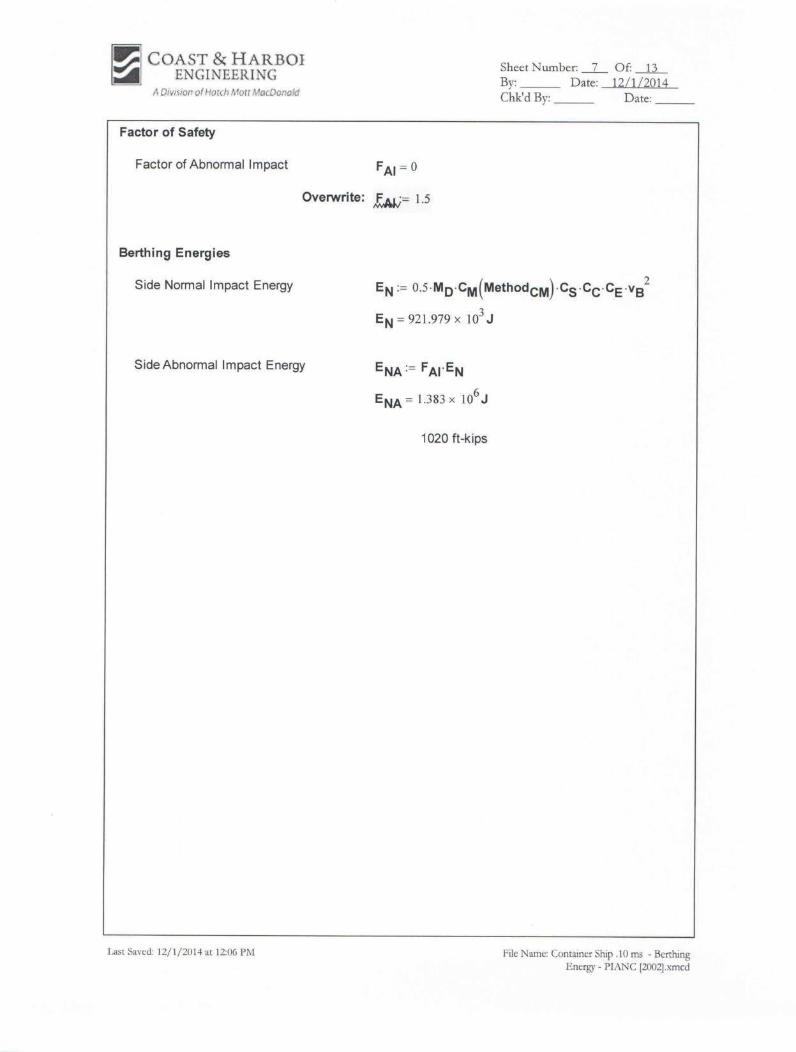
The deterministic method is the most commonly used method for fender design. The
method has been adopted from PIANC (1994). The method’s approach is to calculate
the kinetic energy demand by the design vessel during berthing maneuvers, which has
to be absorbed (resisted) by the fender. The PIANC equation considers other
important factors in the energy calculations such as: virtual mass, softness, berth
configuration, etc.
Ship displacements were calculated using ship dimensions and assumed block
coefficients. The approach velocity (v) is the most influential variable in the
calculation of the berthing energy and is influenced by a large number of factors such
as: physical conditions, ease of navigation, method of berthing, type of vessel, use of
tugs, frequency of berthing, size of vessel, human factor, etc. The velocity for the
design is derived from the recommended approach velocities in Figure 4.2.1 of
PIANC (1994) which depend on ship displacement. For the purposes of the analysis,
it is assumed that the berthing energy is absorbed entirely through elastic deflection
of the fender. Deflections of the wharf and/or the vessel’s hull were neglected.

Technical Report Page 25 Ship Hydrodynamics and Mooring Analysis January 8, 2015 Berth 6 Bulkhead Extension, Port of Port Arthur, TX
7.2. Results
The energy demand findings are summarized in Table 9 below. The required energy
absorption of 1,020 ft-kips for the containership controls fender size selection for the
Future Configuration (extended wharf). For vessels proposed to be moored at the
Proposed B6 Configuration, the break-bulk carrier controls fender size selection, with
required energy absorption of 936 ft-kips. It should be noted that some fender
manufacturers may recommend a type of fender other than a cone fender, such as a
cell fender, for reasons other than their energy absorption performance.
Table 9. Summary of Minimum Fender Requirements
Note:
1. E = Energy Absorption Capacity.
2. FS = Factor of Safety.
3. v = Approach Velocity. Approach velocities used in the Berthing Energy calculations are based on “easy
berthing conditions, exposed” per PIANC guidelines as a function of DWT calculated in the vessel
particulars. Vessel particulars necessary for the Berthing Energy analysis were calculated based on known
vessel particulars.
8. Conclusions
Ship hydrodynamic modeling and mooring analysis were performed by Coast & Harbor
Engineering, a Division of Hatch Mott MacDonald (CHE) upon request from Lockwood,
Andrews and Newnam (LAN) to provide an assessment of vessel mooring and operational
conditions at the proposed Berth 6, Port of Port Arthur, Texas. The present analysis included
four different berthed vessels ranging in length overall from 607 to 1,204 feet subject to
forces and moments generated by passing tankers, as well as environmental forces. The
berthed vessels included a containership, Roll-On/Roll-Off (Ro/Ro) vessel, a break-bulk
carrier and a bulk carrier.
The analysis utilized CHE’s proprietary hydrodynamic modeling tools to develop passing
vessel forces and moments. Static and dynamic mooring analysis simulations were performed
using the OPTIMOOR program. Mooring analysis results were evaluated based on criteria
for mooring line loads provided by Oil Companies International Marine Forum (OCIMF
1978) and criteria for berthed vessel motions provided by Permanent International
Association of Navigation Congresses (PIANC 1995), both coordinated with LAN prior to
the analysis.
7,600 TEU
Containership Ro/Ro Vessel
Break-Bulk Carrier
Bulk Carrier
Berthing Energy 1/3 Point Berth
E: 1020 ft-kips
FS: 1.50
v: 0.32 ft/s
E: 866 ft-kips
FS: 1.50
v: 0.39 ft/s
E: 936 ft-kips
FS: 1.50
v: 0.52 ft/s
E: 798 ft-kips
FS: 1.50
v: 0.39 ft/s
Fender Size (Maritime Int’l.)
MCN 1400 G2.8
E: 1020 ft-kips
R: 415 kips
MCN 1400 G1.9
E: 867 ft-kips
R:339 kips
MCN 1400 G2.3
E: 936 ft-kips
R: 372 kips
MCN 1300 G2.7
E: 803 ft-kips
R: 350 kips

Technical Report Page 26 Ship Hydrodynamics and Mooring Analysis January 8, 2015 Berth 6 Bulkhead Extension, Port of Port Arthur, TX
Analysis results indicate that the moored ships are subject to large passing ship forces and
moments due to the restricted width of the waterway, large passing vessels, and relatively
large berthed vessels. The passing ship forces are comparable in magnitude to those
generated by strong winds blowing off the dock, and for the smaller vessels, winds occurring
during tropical storms/hurricanes.
Transit, maneuvering and berthing of the two larger ships (containership and Ro/Ro vessel)
in this location may not be feasible and should be evaluated. Given the dangerous passing
vessel conditions for the larger berthed vessels, it is not recommended to moor the
containership or Ro/Ro vessel at Berth 6, or possibly at any location in this section of the
waterway. The 771-ft bulk carrier has marginal mooring safety in this location. The
break-bulk carrier appears to be small enough to withstand loads from passing tankers and
for motions and loads in the mooring system to be kept under control.
The results of the analysis and conclusions above are specific to the vessels, waterway
configuration, mooring assumptions, and terminal configuration used in the analysis.
9. References
Coast & Harbor Engineering, 2014. Data Request - Berth 6 Bulkhead Extension
Mooring/Berthing Analysis, Port of Port Arthur, TX. Final Technical Memo dated
November 25, 2014.
Fenical, S., Kolomiets, P., Kivva, S., and M. Zheleznyak. 2006. Numerical Modeling of the
Impacts on Berthed Vessels and Shorelines. International Conference on Coastal
Engineering.
Maritime International. 2014. 2014 Fender Manual.
Oil Companies Marine Forum (OCIMF). 1978. Guidelines and Recommendations for the
Safe Mooring of Large Ships at Piers and Sea Islands. OCIMF 1978.
Permanent International Association of Navigation Congresses (PIANC). 1995. Criteria for
Movement of Moored Ships in Harbours: A Practical Guide. Working Group 24,
Supplement to Bulletin #88. PIANC 1995.
Port of Port Arthur. 2014. 2014 Sailing Schedule.
http://portofportarthur.com/terminal/sailing-schedule/

APPENDIX A
Data Request and Coordination Memorandum

FINAL Technical Memorandum v5 Page 1 Data Request November 25, 2014 Port of Port Arthur Berth 6 Bulkhead Expansion Port Arthur, TX
Final (Version 5)
Data Request Berth 6 Bulkhead Extension Mooring/Berthing Analysis Port of Port Arthur, TX
Coast & Harbor Engineering (CHE), a division of Hatch Mott MacDonald (HMM), is under
contract with Lockwood, Andrews and Newnam (LAN) to provide analysis support services for
the Port of Port Arthur Berth 6 Bulkhead Extension Project. The following technical
memorandum describes the data required for mooring analysis under coastal conditions, dynamic
analysis under passing vessel forces, and berthing analysis. Table 1 provides a list of required
data, suggested parameters if no information is available, as well as brief commentary in some
cases as to the level of importance of each parameter within the analysis.
This memorandum is intended to be a working document that will be updated first by LAN to
provide any available data and either confirm or correct assumptions already made by CHE.
Table 2 provides a location for vessel parameters that may be known to LAN at this time.
Following initial review/revision by LAN, CHE will revise the document to include changes in
appropriate details, any new assumptions, and perhaps (if appropriate at that time) a set of
proposed dynamic mooring analysis Scenarios in Table 3. The document will be considered
final when LAN and CHE have concurrence on the dynamic mooring analysis Scenarios in Table
3, and a final technical memorandum will be sent to LAN.
Table 1. Data Required for Mooring Analysis (LAN, CHE)
Item Parameter Value/Assumption/Source LAN Input
1 Objectives
• Evaluate design loading conditions for berth design subject to passing vessel forces.
• Evaluate potential impacts to loading/unloading operations in terms of berthed vessel movements to within industry recognized limits for surge and sway.
2 Berth drawings (30% Design)
Drawings to be provided by LAN in digital AutoCAD format with known horizontal datum. They need to show horizontal and vertical locations of proposed mooring points, fenders, and dredging depths.
Digital AutoCAD format files provided. Files S-101 and S-150 are for Layout and Typical Section, respectively. (See attachments)
Confirmed, and questions addressed via email.

FINAL Technical Memorandum v5 Page 2 Data Request November 25, 2014 Port of Port Arthur Berth 6 Bulkhead Expansion Port Arthur, TX
3 Fender make and model
Per 30% design plans, the fenders are cell fenders with UHMW polyethylene panels. CHE to measure dimensions on design drawings and assume a make and model with performance data from Trelleborg Marine Systems (http://www.trelleborg.com/en/Marine-Systems/)
Assume either of the following:
• Bridgestone Hypercell
• Maritime International
Cone
Confirmed. Maritime International Cone fender to be assumed.
4 Bollard capacities
LAN to provide allowable horizontal load in bollards if known at this time. If unknown, peak bollard loads will be provided. The assumed bollard capacity does not affect the analysis results.
Provide peak bollard loads
Confirmed
Bollard capacities 250 kips assumed for Berth 6.
In keeping with LAN Design Criteria, use 275 kips. 11/03/2014
5 Waterway bathymetry
LAN to provide waterway bathymetry data in XYZ format and in a known horizontal and vertical datum.
Digital AutoCAD 2-D file (V-XC_TOPO), USACE Plan and Cross-Section at Site and bathymetry data in XYZ format (POPA 09242012.xyz) provided. (See attachments)
Confirmed, and questions addressed via email.
6 Passing vessel speeds and distances
This is an important factor and should be coordinated with Sabine Pilots. In the absence of this coordination, Speeds 4 and 6 knots could be used, traveling along channel centerline in worst-case direction with opposing current. Worst-case direction to be determined during initial testing.
Use speeds of 4 and 6 knots
Confirmed.
7 Moored vessels
• Initially four (4) design vessels have been specified for berthing at the terminal:
1. 7,600 TEU Containership 2. Bulk Carrier 3. Break-Bulk Carrier 4. Ro/Ro Vessel
• For each of these vessels, LAN to provide at a minimum Length Overall (or Length Between Perpendiculars), Beam and Draft.
• Two (2) values of draft should be developed for each vessel: 1) ballast draft for coastal conditions mooring and 2) maximum allowable draft for passing ship mooring.
• See Table 2 for location to fill in this information. If no vessel size details are
See Table 2. Ballasted draft not available at this time.
Confirmed. Passing ship mooring analysis may commence but ballast draft values are required for coastal conditions mooring analysis, which include only wind forces and will be performed at ballast draft and high tide.

FINAL Technical Memorandum v5 Page 3 Data Request November 25, 2014 Port of Port Arthur Berth 6 Bulkhead Expansion Port Arthur, TX
available, a sample real vessel name can be provided to CHE.
• Hull forms will be estimated by CHE and extracted from CHE database. It is assumed that only three (3) vessels will be evaluated in the mooring analysis, so CHE will provide recommendations as to which three (3) are most appropriate.
Please provide ballast drafts as soon as possible, or CHE can make an estimate.
Also, shall the containership be evaluated fully loaded for larger windage area?
Use CHE estimated values for ballast drafts.
Evaluate containership as fully loaded
8
Mooring equipment, or assumed real ship equivalent
To be determined following delivery of detailed ship size data from Item #8 above.
CHE will assume ship mooring equipment information based on similar vessels.
Containership – data for COSCO Long Beach used, and scaled to match new dimensions.
RoRo Vessel – data for Tonsberg used, and scaled to match new dimensions.
Breakbulk Carrier – data for CSL Acadian used, and scaled to match new dimensions.
Agreed
9 Passing vessel
This is an important factor and should be coordinated with Sabine Pilots. In the absence of this coordination, in this area we have used a Suezmax Tanker, 900x164x40. 40-ft draft was reported to be largest draft allowed on the upper Sabine reaches (near Beaumont) in May 2013 meeting with Sabine Pilots.
Use CHE recommended passing vessel
Confirmed.
10 Mooring lines types and capacities
To be determined following delivery of detailed ship size data from Item #8 above.
CHE will assume ship mooring equipment information based on similar vessels.
Containership – data for COSCO Long Beach used.
RoRo Vessel – data for Tonsberg used.
Breakbulk Carrier – data

FINAL Technical Memorandum v5 Page 4 Data Request November 25, 2014 Port of Port Arthur Berth 6 Bulkhead Expansion Port Arthur, TX
for CSL Acadian used.
Agreed
Bulk Carrier – data for CSL Acadian used.
Agreed on 11/03/2014
11 Mooring line pre-tension
10% of the mooring line minimum breaking load (MBL) per recommendation by OCIMF (2008)
Agreed
Confirmed.
12 Winch brake limit
60% of the mooring line minimum breaking load (MBL) per recommendation by OCIMF (2008)
Agreed
Confirmed.
13 Wind-waves None Agreed
Confirmed.
14 Wind
• Per the CHE Scope of Work, no wind
analysis or extreme wind prediction is
included.
• Static mooring analysis will determine
mooring capability under strong winds;
however the results will not correlate to
return periods for specific wind speeds.
• A steady wind speed and direction may be
included in the dynamic passing ship
simulations if desired.
• LAN to specify steady wind speed and
direction to be included in passing ship
dynamic mooring analysis.
Use an assumed maximum wind speed of 60 mph and wind directions to generate worst line load effects.
Suggest eliminating winds for now. Loads will be a challenge already and winds are uncertain.
Agreed, pending results of initial evaluations
15 Tidal/river current
This is an important factor and should be coordinated with Sabine Pilots. In the absence of this coordination, LAN to provide a typical flood/ebb current speed in the center of the channel to include.
Note: Passing ships will be assumed to run opposite to the current direction, which will effectively increase the passing ship speed through the water.
Use flood/ebb current speed of 2-3 knots.
Suggest eliminating currents for now. Loads will be a challenge already and currents uncertain
Agreed, pending results of initial evaluations
16 Drift Likely to be a minor factor here. It is suggested that we neglect drift angle (crabbing) in the simulation.
Agreed
Confirmed.
17 Tides Passing ship events are assumed to occur at Mean Lower Low Water tidal elevation (slightly conservative). LAN to provide vertical datum
See attached file: Datum Table
FINAL Technical Memorandum v5 Page 5 Data Request November 25, 2014 Port of Port Arthur Berth 6 Bulkhead Expansion Port Arthur, TX
table to allow conversions between elevation data for the terminal, bathymetry, and tides.
Confirmed.
18
Sources of mooring analysis criteria
• Ship motion criteria shall be derived from
PIANC (Criteria for Movement of Moored
Ships in Harbours: A Practical Guide, 1995).
• Peak mooring line force criteria shall be
derived from OCIMF(Mooring Equipment
Guidelines - 3rd Edition, 2008)
Agreed
Confirmed.
19
Guidelines from above references to be used in the analysis
• Ship motions for Safe Working Conditions (PIANC 1995) will be prescribed based on Surge, Sway (feet):
o 7600 TEU containership (50% efficiency) = +/-3.3, 3.9
o Bulk Carrier (general cargo) = +/-3.3, 3.3
o Break-Bulk Carrier (general cargo) = +/-3.3, 3.3
o Ro/Ro Vessel (side ramp/rollers) = +/-2.0, 2.0
• Mooring line forces for steel wire (if any is used here, OCIMF): less than 55% of MBL.
• Mooring line forces for synthetic lines (polypropylene /polyethylene), OCIMF: less than 50% of MBL.
• Assumed mooring winch brake limits for initiation of payout (OCIMF): 60% of MBL.
• Fender loads and compression: from Trelleborg (2014) Maritime International (2014).
Agreed
It is recommended to eliminate the larger bulk carrier as we are scoped to evaluate only 3 vessels.
No ships will have steel wire, all use synthetic lines.
Fender data will be taken from Maritime International.
Bulk carrier added back into analysis 11/3/14, fixed sway limit on break-bulk.
Agreed on 11/03/2014
Table 2. Design Vessel Particulars
Particular Moored Vessel 1
Moored Vessel 2
Moored Vessel 3
Moored Vessel 4
1
Passing Vessel 1
7,600 TEU Containership
Bulk Carrier Break-bulk Carrier
Ro/Ro Vessel
Suezmax Tanker
Length Overall [feet] 1204 771 607 942 900
Beam [feet] 138 141 106 106 164
Maximum Allowable Draft [feet]
43.6 40 39.4 40.7 40.02
Ballast Draft [feet]
Notes:
1. Only 3 moored vessels included in the Scope of Work. Moored vessel 2 was removed as its size fits
between other vessels and its mooring would be very similar to moored vessel 3. Moored vessel 2
determined to be useful addition, added back into analysis upon agreement from CHE on
11/3/14. Agreed on 11/03/2014
2. Maximum draft in the channel per Sabine Pilots meeting May 2013.

FINAL Technical Memorandum v5 Page 6 Data Request November 25, 2014 Port of Port Arthur Berth 6 Bulkhead Expansion Port Arthur, TX
Table 3. Dynamic Mooring Analysis Scenarios
Notes:
1. Parameters in passing ship simulations are for example only, and are subject to change.
2. Passing ship hydrodynamic simulations are limited to six (6) scenarios in original scope of work. A total
of 7 passing ship simulations agreed upon by CHE on 11/3/14. Agreed on 11/03/2014
3. Ships pass moving inbound along channel centerline.
• Scenarios to be mutually agreed by LAN and CHE
• AGREED
• Scenarios 1-3 suggested as initial testing, to be reviewed and coordinated for follow-on
scenarios.
• Agreed, pending results of initial evaluations.
• Scenarios 4-7 proposed by CHE on 11/3/14. Agreed on 11/03/2014
Mooring Layouts
1. Containership
a. 1200-ft containership to fit entirely within a future elongated Berth 6.
b. Moored port side to.
c. Bow located 100 feet from end of Berth 6 so that all lines use new Berth 6 bollards.
d. Berth 5 assumes same depth and slopes (48.78’ NAVD88). Assumption ok for now
e. Dredge prism developed using 30-ft offset from stern of ship
f. All same slopes as in LAN 30% design
g. Continuous wharf assumed all the way to station 3+50, same cross-section as proposed at
Berth 6, mooring/breasting structure removed.
Scenario Berthing Location
Berthed Ship Passing Ship Speed [kts]
Tidal Current
1 Figure 1 Containership 900-ft tanker 4 none
2 Figure 2 RoRo Vessel 900-ft tanker 4 none
3 Figure 3 Breakbulk Carrier 900-ft tanker 4 none
4 Figure 1 Containership 900-ft tanker 6 none
5 Figure 2 RoRo Vessel 900-ft tanker 6 none
6 Figure 3 Breakbulk Carrier 900-ft tanker 6 none
7 Figure 1 Bulk Carrier 900-ft tanker 6 none
8
9
10

FINAL Technical Memorandum v5 Page 7 Data Request November 25, 2014 Port of Port Arthur Berth 6 Bulkhead Expansion Port Arthur, TX
Figure 1. Moored containership
2. Ro-Ro Vessel
a. 942-ft RoRo ship sits at Berth 6 and overlaps onto Berth 5.
b. Stern lines moor to bollards on Berth 5.
c. Berth 5 assumes same depth and slopes (48.78’ NAVD88).
d. Moored starboard side to, to allow stern ramps to offload onto wharf.
e. Bow located at soutwest turn in dredge cut (no modification to the 30% design dredge
prism provided by LAN).
f. All same slopes as in LAN 30% design.
Figure 2. Moored RoRo vessel
3. Breakbulk Carrier
a. 607-ft Breakbulk carrier sits within Berth 6
b. Stern lines moor to mooring/breasting dolphins.
c. Berth 5 assumes same depth and slopes (48.78’ NAVD88).
d. Moored port side to.
e. Stern located in conventient position to allow use of the mooring/breasting dolphin by its
stern lines, as it cannot fit entirely within the bulkhead area.
f. No modification to the 30% design dredge prism provided by LAN.
g. All same slopes as in LAN 30% design.

FINAL Technical Memorandum v5 Page 8 Data Request November 25, 2014 Port of Port Arthur Berth 6 Bulkhead Expansion Port Arthur, TX
h. Bow lines moor to bollards on Berth 6.
Figure 3. Moored Breakbulk carrier
References
Oil Companies Marine Forum (OCIMF). 2008. Mooring Equipment Guidelines - 3rd Edition,
2008.
Permanent International Association of Navigation Congresses (PIANC). 1995. Criteria for
Movement of Moored Ships in Harbours: A Practical Guide. Working Group 24,
Supplement to Bulletin #88. Permanent International Association of Navigation
Congresses, 1995.
Trelleborg Marine Systems. 2013. Trelleborg Fender Systems Make Certain (Catalog)

APPENDIX B
Passing Vessel Forces and Moments Scenarios 1-8
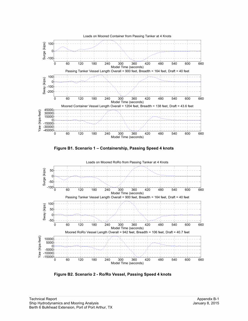
Technical Report Appendix B-1 Ship Hydrodynamics and Mooring Analysis January 8, 2015 Berth 6 Bulkhead Extension, Port of Port Arthur, TX
Figure B1. Scenario 1 – Containership, Passing Speed 4 knots
Figure B2. Scenario 2 - Ro/Ro Vessel, Passing Speed 4 knots
0 60 120 180 240 300 360 420 480 540 600 660
-100
0
100S
urg
e (
kip
s)
Model Time (seconds)
Loads on Moored Container from Passing Tanker at 4 Knots
0 60 120 180 240 300 360 420 480 540 600 660
-200
-100
0
100
Sw
ay (
kip
s)
Model Time (seconds)
Passing Tanker Vessel Length Overall = 900 feet, Breadth = 164 feet, Draft = 40 feet
0 60 120 180 240 300 360 420 480 540 600 660 -45000 -30000 -15000
0 15000 30000 45000
Ya
w (
kip
s-f
ee
t)
Model Time (seconds)
Moored Container Vessel Length Overall = 1204 feet, Breadth = 138 feet, Draft = 43.6 feet
0 60 120 180 240 300 360 420 480 540 600 660-100
-50
0
50
Surg
e (
kip
s)
Model Time (seconds)
Loads on Moored RoRo from Passing Tanker at 4 Knots
0 60 120 180 240 300 360 420 480 540 600 660
-50
0
50
100
Sw
ay (
kip
s)
Model Time (seconds)
Passing Tanker Vessel Length Overall = 900 feet, Breadth = 164 feet, Draft = 40 feet
0 60 120 180 240 300 360 420 480 540 600 660 -15000 -10000 -5000
0 5000 10000
Ya
w (
kip
s-f
ee
t)
Model Time (seconds)
Moored RoRo Vessel Length Overall = 942 feet, Breadth = 106 feet, Draft = 40.7 feet

Technical Report Appendix B-2 Ship Hydrodynamics and Mooring Analysis January 8, 2015 Berth 6 Bulkhead Extension, Port of Port Arthur, TX
Figure B3. Scenario 2 - Ro/Ro Vessel Shifted 85 feet, Passing Speed 4 knots
Figure B4. Scenario 3 – Break-bulk Carrier, Passing Speed 4 knots
0 60 120 180 240 300 360 420 480 540 600 660
-50
0
50S
urg
e (
kip
s)
Model Time (seconds)
Loads on Moored RoRo-Shifted from Passing Tanker at 4 Knots
0 60 120 180 240 300 360 420 480 540 600 660
-50
0
50
100
Sw
ay (
kip
s)
Model Time (seconds)
Passing Tanker Vessel Length Overall = 900 feet, Breadth = 164 feet, Draft = 40 feet
0 60 120 180 240 300 360 420 480 540 600 660
-10000 -5000
0 5000 10000
Ya
w (
kip
s-f
ee
t)
Model Time (seconds)
Moored RoRo-Shifted Vessel Length Overall = 942 feet, Breadth = 106 feet, Draft = 40.7 feet
0 60 120 180 240 300 360 420 480 540 600 660
-50
0
50
Surg
e (
kip
s)
Model Time (seconds)
Loads on Moored Breakbulk from Passing Tanker at 4 Knots
0 60 120 180 240 300 360 420 480 540 600 660
-50
0
Sw
ay (
kip
s)
Model Time (seconds)
Passing Tanker Vessel Length Overall = 900 feet, Breadth = 164 feet, Draft = 40 feet
0 60 120 180 240 300 360 420 480 540 600 660
-5000
0
5000
Ya
w (
kip
s-f
ee
t)
Model Time (seconds)
Moored Breakbulk Vessel Length Overall = 607 feet, Breadth = 106 feet, Draft = 39.4 feet
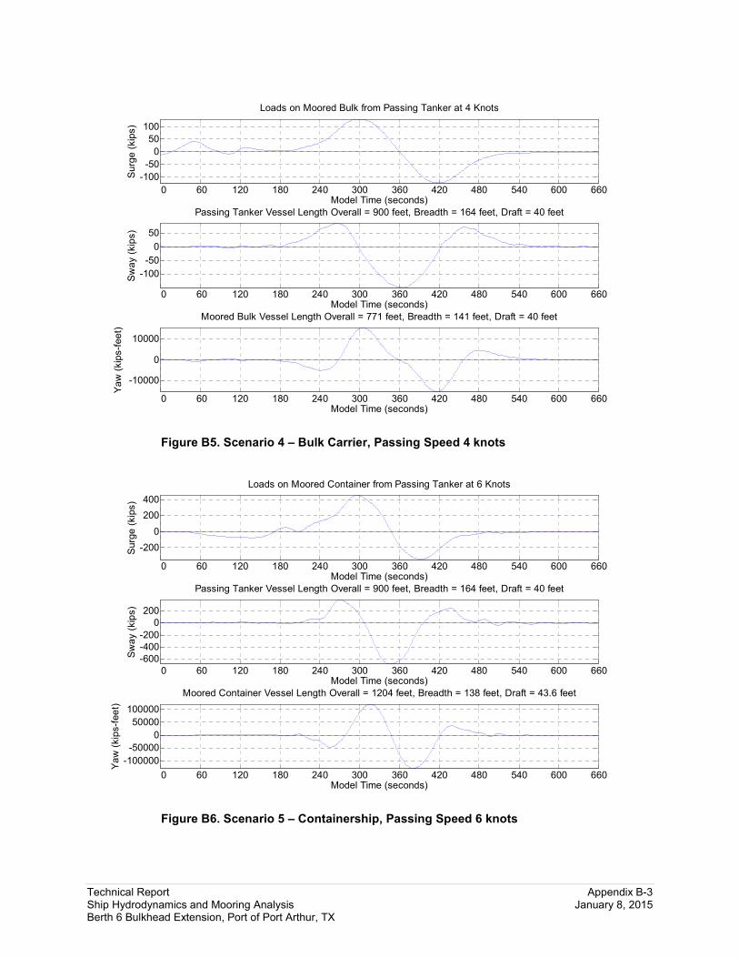
Technical Report Appendix B-3 Ship Hydrodynamics and Mooring Analysis January 8, 2015 Berth 6 Bulkhead Extension, Port of Port Arthur, TX
Figure B5. Scenario 4 – Bulk Carrier, Passing Speed 4 knots
Figure B6. Scenario 5 – Containership, Passing Speed 6 knots
0 60 120 180 240 300 360 420 480 540 600 660
-100
-50
0
50
100S
urg
e (
kip
s)
Model Time (seconds)
Loads on Moored Bulk from Passing Tanker at 4 Knots
0 60 120 180 240 300 360 420 480 540 600 660
-100
-50
0
50
Sw
ay (
kip
s)
Model Time (seconds)
Passing Tanker Vessel Length Overall = 900 feet, Breadth = 164 feet, Draft = 40 feet
0 60 120 180 240 300 360 420 480 540 600 660
-10000
0
10000
Ya
w (
kip
s-f
ee
t)
Model Time (seconds)
Moored Bulk Vessel Length Overall = 771 feet, Breadth = 141 feet, Draft = 40 feet
0 60 120 180 240 300 360 420 480 540 600 660
-200
0
200
400
Surg
e (
kip
s)
Model Time (seconds)
Loads on Moored Container from Passing Tanker at 6 Knots
0 60 120 180 240 300 360 420 480 540 600 660
-600
-400
-200
0
200
Sw
ay (
kip
s)
Model Time (seconds)
Passing Tanker Vessel Length Overall = 900 feet, Breadth = 164 feet, Draft = 40 feet
0 60 120 180 240 300 360 420 480 540 600 660
-100000
-50000
0
50000
100000
Ya
w (
kip
s-f
ee
t)
Model Time (seconds)
Moored Container Vessel Length Overall = 1204 feet, Breadth = 138 feet, Draft = 43.6 feet

Technical Report Appendix B-4 Ship Hydrodynamics and Mooring Analysis January 8, 2015 Berth 6 Bulkhead Extension, Port of Port Arthur, TX
Figure B7. Scenario 6 – Ro/Ro Vessel, Passing Speed 6 knots
Figure B8. Scenario 6 – Ro/Ro Vessel Shifted 85 feet, Passing Speed 6 knots
0 60 120 180 240 300 360 420 480 540 600 660
-200
-100
0
100
200S
urg
e (
kip
s)
Model Time (seconds)
Loads on Moored RoRo from Passing Tanker at 6 Knots
0 60 120 180 240 300 360 420 480 540 600 660
-100
0
100
200
300
Sw
ay (
kip
s)
Model Time (seconds)
Passing Tanker Vessel Length Overall = 900 feet, Breadth = 164 feet, Draft = 40 feet
0 60 120 180 240 300 360 420 480 540 600 660
-30000 -20000 -10000
0 10000 20000 30000
Ya
w (
kip
s-f
ee
t)
Model Time (seconds)
Moored RoRo Vessel Length Overall = 942 feet, Breadth = 106 feet, Draft = 40.7 feet
0 60 120 180 240 300 360 420 480 540 600 660
-200
-100
0
100
200
Surg
e (
kip
s)
Model Time (seconds)
Loads on Moored RoRo-Shifted from Passing Tanker at 6 Knots
0 60 120 180 240 300 360 420 480 540 600 660
-100
0
100
200
300
Sw
ay (
kip
s)
Model Time (seconds)
Passing Tanker Vessel Length Overall = 900 feet, Breadth = 164 feet, Draft = 40 feet
0 60 120 180 240 300 360 420 480 540 600 660
-30000 -20000 -10000
0 10000 20000 30000
Ya
w (
kip
s-f
ee
t)
Model Time (seconds)
Moored RoRo-Shifted Vessel Length Overall = 942 feet, Breadth = 106 feet, Draft = 40.7 feet

Technical Report Appendix B-5 Ship Hydrodynamics and Mooring Analysis January 8, 2015 Berth 6 Bulkhead Extension, Port of Port Arthur, TX
Figure B9. Scenario 7 – Break-bulk Carrier, Passing Speed 6 knots
Figure B20. Scenario 8 – Bulk Carrier, Passing Speed 6 knots
0 60 120 180 240 300 360 420 480 540 600 660
-100
0
100
200S
urg
e (
kip
s)
Model Time (seconds)
Loads on Moored Breakbulk from Passing Tanker at 6 Knots
0 60 120 180 240 300 360 420 480 540 600 660
-100
0
100
Sw
ay (
kip
s)
Model Time (seconds)
Passing Tanker Vessel Length Overall = 900 feet, Breadth = 164 feet, Draft = 40 feet
0 60 120 180 240 300 360 420 480 540 600 660 -15000 -10000 -5000
0 5000 10000
Ya
w (
kip
s-f
ee
t)
Model Time (seconds)
Moored Breakbulk Vessel Length Overall = 607 feet, Breadth = 106 feet, Draft = 39.4 feet
0 60 120 180 240 300 360 420 480 540 600 660-300-200-100
0 100 200 300
Surg
e (
kip
s)
Model Time (seconds)
Loads on Moored Bulk from Passing Tanker at 6 Knots
0 60 120 180 240 300 360 420 480 540 600 660
-300-200-100
0 100 200
Sw
ay (
kip
s)
Model Time (seconds)
Passing Tanker Vessel Length Overall = 900 feet, Breadth = 164 feet, Draft = 40 feet
0 60 120 180 240 300 360 420 480 540 600 660
-30000 -20000 -10000
0 10000 20000 30000
Ya
w (
kip
s-f
ee
t)
Model Time (seconds)
Moored Bulk Vessel Length Overall = 771 feet, Breadth = 141 feet, Draft = 40 feet

APPENDIX C
Passing Vessel Dynamic Mooring Analysis Results

Technical Report Appendix C-1 Ship Hydrodynamics and Mooring Analysis January 8, 2015 Berth 6 Bulkhead Extension, Port of Port Arthur, TX
Figure C1. Scenario 1 – Containership, Passing Speed 4 knots
cc dd ee ff gg hh ii jj kk ll mm nn oo pp qq rr ss tt uu vv ww xx0
100
200
300
400
500
600
Fender
Forc
e (
kip
s)
Force
Capacity
A B C D E F 0
50
100
150
200
250
300
350
Bollard
Forc
e (
kip
s)
Force
Capacity
1 2 3 4 5 6 7 8 9 10 11 120
50
100
150
200
250
50% MBL = 113.5 kips
100 % MBL = 227 kips
Mooring Line
Forc
e (
kip
s)
-12 -9 -6 -3 0 3 6 9 12-12
-9
-6
-3
0
3
6
9
12
Surge (feet), "+" Astern
Sw
ay (
fee
t), "+
" to
Stb
d
Initial Position
Acceptable Limits

Technical Report Appendix C-2 Ship Hydrodynamics and Mooring Analysis January 8, 2015 Berth 6 Bulkhead Extension, Port of Port Arthur, TX
Figure C2. Scenario 2 - Ro/Ro Vessel, Passing Speed 4 knots
bb cc dd ee ff gg hh ii jj kk ll mm0
100
200
300
400
500
600
Fender
Forc
e (
kip
s)
Force
Capacity
A B C N V W 0
50
100
150
200
250
300
350
Bollard
Forc
e (
kip
s)
Force
Capacity
1 2 3 4 5 6 7 8 9 10 11 120
20
40
60
80
100
120
140
160
180
200
50% MBL = 85.5 kips
100 % MBL = 171 kips
Mooring Line
Forc
e (
kip
s)
-12 -9 -6 -3 0 3 6 9 12-12
-9
-6
-3
0
3
6
9
12
Surge (feet), "+" Astern
Sw
ay (
fee
t), "+
" to
Stb
d
Initial Position
Acceptable Limits

Technical Report Appendix C-3 Ship Hydrodynamics and Mooring Analysis January 8, 2015 Berth 6 Bulkhead Extension, Port of Port Arthur, TX
Figure C3. Scenario 2 - Ro/Ro Vessel Shifted 85 feet, Passing Speed 4 knots
bb cc dd ee ff gg hh ii jj kk ll mm nn oo0
100
200
300
400
500
600
Fender
Forc
e (
kip
s)
Force
Capacity
A B D P X Y 0
50
100
150
200
250
300
350
Bollard
Forc
e (
kip
s)
Force
Capacity
1 2 3 4 5 6 7 8 9 10 11 120
20
40
60
80
100
120
140
160
180
200
50% MBL = 85.5 kips
100 % MBL = 171 kips
Mooring Line
Forc
e (
kip
s)
-12 -9 -6 -3 0 3 6 9 12-12
-9
-6
-3
0
3
6
9
12
Surge (feet), "+" Astern
Sw
ay (
fee
t), "+
" to
Stb
d
Initial Position
Acceptable Limits

Technical Report Appendix C-4 Ship Hydrodynamics and Mooring Analysis January 8, 2015 Berth 6 Bulkhead Extension, Port of Port Arthur, TX
Figure C4. Scenario 2 - Ro/Ro Vessel Shifted 85 feet, Dolphins Shifted 42 feet, Passing Speed 4 knots
bb cc dd ee ff gg hh ii jj kk ll mm nn oo0
100
200
300
400
500
600
Fender
Forc
e (
kip
s)
Force
Capacity
A B D P X Y 0
50
100
150
200
250
300
350
Bollard
Forc
e (
kip
s)
Force
Capacity
1 2 3 4 5 6 7 8 9 10 11 120
20
40
60
80
100
120
140
160
180
200
50% MBL = 85.5 kips
100 % MBL = 171 kips
Mooring Line
Forc
e (
kip
s)
-12 -9 -6 -3 0 3 6 9 12-12
-9
-6
-3
0
3
6
9
12
Surge (feet), "+" Astern
Sw
ay (
fee
t), "+
" to
Stb
d
Initial Position
Acceptable Limits

Technical Report Appendix C-5 Ship Hydrodynamics and Mooring Analysis January 8, 2015 Berth 6 Bulkhead Extension, Port of Port Arthur, TX
Figure C5. Scenario 3 – Break-bulk Carrier, Passing Speed 4 knots
aa bb cc dd ee ff gg hh0
100
200
300
400
500
600
Fender
Forc
e (
kip
s)
Force
Capacity
A B C D E F 0
50
100
150
200
250
300
350
Bollard
Forc
e (
kip
s)
Force
Capacity
1 2 3 4 5 6 7 8 9 10 11 120
20
40
60
80
100
120
140
160
180
200
50% MBL = 95.5 kips
100 % MBL = 191 kips
Mooring Line
Forc
e (
kip
s)
-12 -9 -6 -3 0 3 6 9 12-12
-9
-6
-3
0
3
6
9
12
Surge (feet), "+" Astern
Sw
ay (
fee
t), "+
" to
Stb
d
Initial Position
Acceptable Limits

Technical Report Appendix C-6 Ship Hydrodynamics and Mooring Analysis January 8, 2015 Berth 6 Bulkhead Extension, Port of Port Arthur, TX
Figure C6. Scenario 4 – Bulk Carrier, Passing Speed 4 knots
aa bb cc dd ee ff gg hh ii jj kk0
100
200
300
400
500
600
Fender
Forc
e (
kip
s)
Force
Capacity
A B G M R S 0
50
100
150
200
250
300
350
Bollard
Forc
e (
kip
s)
Force
Capacity
1 2 3 4 5 6 7 8 9 10 11 120
20
40
60
80
100
120
140
160
180
200
50% MBL = 95.5 kips
100 % MBL = 191 kips
Mooring Line
Forc
e (
kip
s)
-12 -9 -6 -3 0 3 6 9 12-12
-9
-6
-3
0
3
6
9
12
Surge (feet), "+" Astern
Sw
ay (
fee
t), "+
" to
Stb
d
Initial Position
Acceptable Limits

Technical Report Appendix C-7 Ship Hydrodynamics and Mooring Analysis January 8, 2015 Berth 6 Bulkhead Extension, Port of Port Arthur, TX
Figure C7. Scenario 5 – Containership, Passing Speed 6 knots
cc dd ee ff gg hh ii jj kk ll mm nn oo pp qq rr ss tt uu vv ww xx0
100
200
300
400
500
600
Fender
Forc
e (
kip
s)
Force
Capacity
A B C D E F 0
50
100
150
200
250
300
350
Bollard
Forc
e (
kip
s)
Force
Capacity
1 2 3 4 5 6 7 8 9 10 11 120
50
100
150
200
250
50% MBL = 113.5 kips
100 % MBL = 227 kips
Mooring Line
Forc
e (
kip
s)
-30 -20 -10 0 10 20 30-30
-20
-10
0
10
20
30
Surge (feet), "+" Astern
Sw
ay (
fee
t), "+
" to
Stb
d
Initial Position
Acceptable Limits

Technical Report Appendix C-8 Ship Hydrodynamics and Mooring Analysis January 8, 2015 Berth 6 Bulkhead Extension, Port of Port Arthur, TX
Figure C8. Scenario 6 – Ro/Ro Vessel, Passing Speed 6 knots
bb cc dd ee ff gg hh ii jj kk ll mm0
100
200
300
400
500
600
Fender
Forc
e (
kip
s)
Force
Capacity
A B C N V W 0
50
100
150
200
250
300
350
Bollard
Forc
e (
kip
s)
Force
Capacity
1 2 3 4 5 6 7 8 9 10 11 120
20
40
60
80
100
120
140
160
180
200
50% MBL = 85.5 kips
100 % MBL = 171 kips
Mooring Line
Forc
e (
kip
s)
-30 -20 -10 0 10 20 30-30
-20
-10
0
10
20
30
Surge (feet), "+" Astern
Sw
ay (
fee
t), "+
" to
Stb
d
Initial Position
Acceptable Limits

Technical Report Appendix C-9 Ship Hydrodynamics and Mooring Analysis January 8, 2015 Berth 6 Bulkhead Extension, Port of Port Arthur, TX
Figure C9. Scenario 6 – Ro/Ro Vessel Shifted 85 feet, Passing Speed 6 knots
bb cc dd ee ff gg hh ii jj kk ll mm nn oo0
100
200
300
400
500
600
Fender
Forc
e (
kip
s)
Force
Capacity
A B D P X Y 0
50
100
150
200
250
300
350
Bollard
Forc
e (
kip
s)
Force
Capacity
1 2 3 4 5 6 7 8 9 10 11 120
20
40
60
80
100
120
140
160
180
200
50% MBL = 85.5 kips
100 % MBL = 171 kips
Mooring Line
Forc
e (
kip
s)
-20 -15 -10 -5 0 5 10 15 20-20
-15
-10
-5
0
5
10
15
20
Surge (feet), "+" Astern
Sw
ay (
fee
t), "+
" to
Stb
d
Initial Position
Acceptable Limits
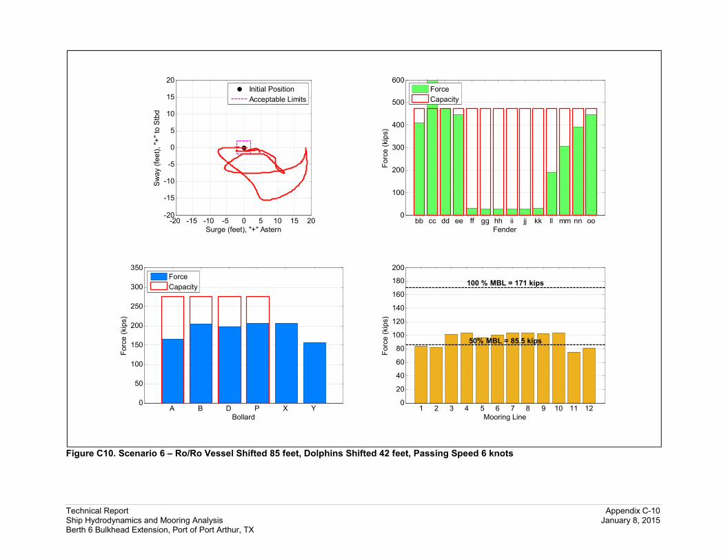
Technical Report Appendix C-10 Ship Hydrodynamics and Mooring Analysis January 8, 2015 Berth 6 Bulkhead Extension, Port of Port Arthur, TX
Figure C10. Scenario 6 – Ro/Ro Vessel Shifted 85 feet, Dolphins Shifted 42 feet, Passing Speed 6 knots
bb cc dd ee ff gg hh ii jj kk ll mm nn oo0
100
200
300
400
500
600
Fender
Forc
e (
kip
s)
Force
Capacity
A B D P X Y 0
50
100
150
200
250
300
350
Bollard
Forc
e (
kip
s)
Force
Capacity
1 2 3 4 5 6 7 8 9 10 11 120
20
40
60
80
100
120
140
160
180
200
50% MBL = 85.5 kips
100 % MBL = 171 kips
Mooring Line
Forc
e (
kip
s)
-20 -15 -10 -5 0 5 10 15 20-20
-15
-10
-5
0
5
10
15
20
Surge (feet), "+" Astern
Sw
ay (
fee
t), "+
" to
Stb
d
Initial Position
Acceptable Limits

Technical Report Appendix C-11 Ship Hydrodynamics and Mooring Analysis January 8, 2015 Berth 6 Bulkhead Extension, Port of Port Arthur, TX
Figure C11. Scenario 7 – Break-bulk Carrier, Passing Speed 6 knots
aa bb cc dd ee ff gg hh0
100
200
300
400
500
600
Fender
Forc
e (
kip
s)
Force
Capacity
A B C D E F 0
50
100
150
200
250
300
350
Bollard
Forc
e (
kip
s)
Force
Capacity
1 2 3 4 5 6 7 8 9 10 11 120
20
40
60
80
100
120
140
160
180
200
50% MBL = 95.5 kips
100 % MBL = 191 kips
Mooring Line
Forc
e (
kip
s)
-12 -9 -6 -3 0 3 6 9 12-12
-9
-6
-3
0
3
6
9
12
Surge (feet), "+" Astern
Sw
ay (
fee
t), "+
" to
Stb
d
Initial Position
Acceptable Limits

Technical Report Appendix C-12 Ship Hydrodynamics and Mooring Analysis January 8, 2015 Berth 6 Bulkhead Extension, Port of Port Arthur, TX
Figure C12. Scenario 8 – Bulk Carrier, Passing Speed 6 knots
aa bb cc dd ee ff gg hh ii jj kk0
100
200
300
400
500
600
Fender
Forc
e (
kip
s)
Force
Capacity
A B G M R S 0
50
100
150
200
250
300
350
Bollard
Forc
e (
kip
s)
Force
Capacity
1 2 3 4 5 6 7 8 9 10 11 120
20
40
60
80
100
120
140
160
180
200
50% MBL = 95.5 kips
100 % MBL = 191 kips
Mooring Line
Forc
e (
kip
s)
-15 -12 -9 -6 -3 0 3 6 9 12 15-15
-12
-9
-6
-3
0
3
6
9
12
15
Surge (feet), "+" Astern
Sw
ay (
fee
t), "+
" to
Stb
d
Initial Position
Acceptable Limits

APPENDIX D
Berthing Analysis Results


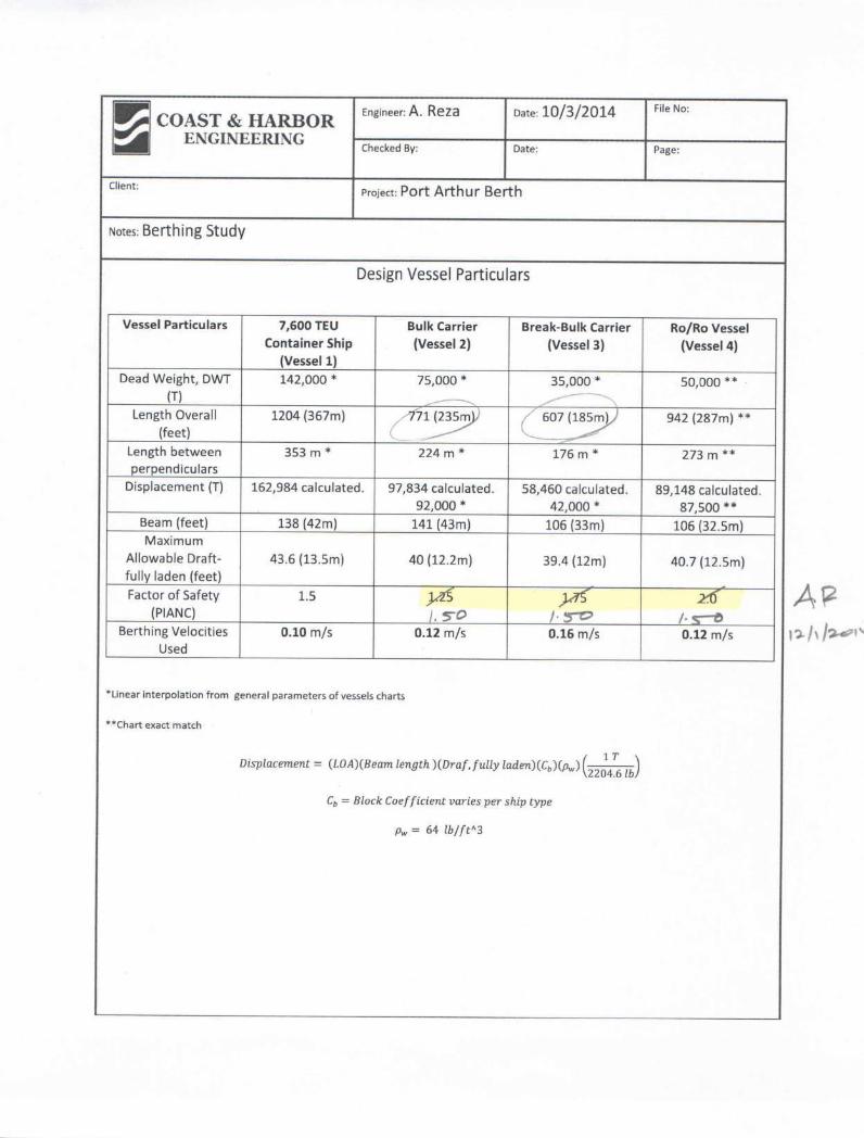


Engineer: A. Reza Date: 12/1/2014 File No:
Checked By: Date: Page:
Client: Project: Port Arthur Berth
Notes: Berthing Study
Berthing Energy Summary – F.S 1.5 for all Vessels
Vessel
Berthing velocity:
.10 m/s
Abnormal Impact
Energy
KN-m
Berthing velocity:
.12 m/s
Abnormal Impact
Energy
KN-m
Berthing velocity:
.16 m/s
Abnormal Impact
Energy
KN-m
Container Ship
(Vessel 1)
FS= 1.50
1383 KN-m
(1020 ft-kip)
Ro/Ro
(Vessel 2)
FS = 1.50
1174 KN-m
(866 ft-kip)
Break-Bulk Carrier
(Vessel 3)
1.50
1269 KN-m
(936 ft-kip)
Bulk Carrier
(Vessel 4)
FS: 1.50
1082 KN-m
(798 ft-kip)