technical report documentation page 1. report no. 2 ... · 2. repair decision flowchart for routine...
TRANSCRIPT

Technical Report Documentation Page 1. Report No. FHWA/TX-08/0-5821-P2
2. Government Accession No.
3. Recipient's Catalog No. 5. Report Date April 2008 Published: September 2008
4. Title and Subtitle EVALUATION AND SELECTION GUIDE OF METHOD OF REPAIR FOR ROUTINE MAINTENANCE
6. Performing Organization Code
7. Author(s) Youn su Jung, Thomas J. Freeman and Dan G. Zollinger
8. Performing Organization Report No. Report 0-5821-P2 10. Work Unit No. (TRAIS)
9. Performing Organization Name and Address Texas Transportation Institute The Texas A&M University System College Station, Texas 77843-3135
11. Contract or Grant No. Project 0-5821 13. Type of Report and Period Covered Product
12. Sponsoring Agency Name and Address Texas Department of Transportation Research and Technology Implementation Office P. O. Box 5080 Austin, Texas 78763-5080
14. Sponsoring Agency Code
15. Supplementary Notes Project performed in cooperation with the Texas Department of Transportation and the Federal Highway Administration. Project Title: Develop Guidelines for Routine Maintenance of Concrete Pavement URL:http://tti.tamu.edu/documents/0-5821-P2.pdf 16. Abstract
The objective of this field guideline is to provide assistance for the pavement evaluation and selection of method of repair for routine maintenance relative to the extension of service life. First, a strategic overview of routine maintenance activities in terms of pavement condition, assessment, and recommendations for repairs, and second, the comparison of selected routine maintenance treatments in terms of repair cost, life extension, and working time are summarized in the tables.
This guideline includes the following: pavement condition evaluation techniques, repair decision flowchart for
routine maintenance, detail sheets. Because pavement condition evaluation is the key to determining proper routine maintenance activities, it is needed to validate the extent of distress related damage, the quality of drainage, and relative base/subgrade layer strength using NDT evaluation techniques. Pavement distress condition is considered relative to functional and structural performance in the decision process. Based on the pavement condition evaluation, decision flowchart provides guidance for effective routine maintenance. Moreover, this report introduces the detail plans of current concrete pavement repair methods using many state departments of transportation (DOTs) and the American Concrete Pavement Association (ACPA) to provide various applications for routine maintenance. The original plans of DOTs used in this chapter are attached in Appendix B and special specifications are attached in Appendix C.
17. Key Words Routine Maintenance, Field Guidelines, Pavement Condition Evaluation, Decision Flowchart, Repair
18. Distribution Statement No Restrictions. This document is available to the public through NTIS: National Technical Information Service Springfield, Virginia 22161 http://www.ntis.gov
19. Security Classif.(of this report) Unclassified
20. Security Classif.(of this page) Unclassified
21. No. of Pages 102
22. Price
Form DOT F 1700.7 (8-72) Reproduction of completed page authorized


iii
EVALUATION AND SELECTION GUIDE OF METHOD OF REPAIR FOR ROUTINE MAINTENANCE
by
Youn su Jung Graduate Research Assistant
Texas Transportation Institute
Thomas J. Freeman Engineering Research Associate Texas Transportation Institute
and
Dan G. Zollinger Program Manager
Texas Transportation Institute
Product 0-5821-P2 Project 0-5821
Project Title: Develop Guidelines for Routine Maintenance of Concrete Pavement
Performed in cooperation with the Texas Department of Transportation
and the Federal Highway Administration
April 2008 Published: September 2008
TEXAS TRANSPORTATION INSTITUTE The Texas A&M University System College Station, Texas 77843-3135


v
DISCLAIMER The contents of this report reflect the views of the authors, who are responsible
for the facts and the accuracy of the data presented herein. The contents do not
necessarily reflect the official view or policies of the Federal Highway Administration
(FHWA) or the Texas Department of Transportation (TxDOT). This report does not
constitute a standard, specification, or regulation. Its contents are not intended for
construction, bidding, or permit purposes. The use and names of specific products or
manufacturers listed herein does not imply endorsement of those products or
manufacturers. The engineer in charge of the project was Dan G. Zollinger, Texas P.E.
#67129.

vi
ACKNOWLEDGMENTS This project was conducted in cooperation with TxDOT and FHWA. The authors
wish to express their appreciation to the Federal Highway Administration and the Texas
Department of Transportation personnel for their support throughout this project, as well
as the project director and members of TxDOT’s project monitoring committee.

vii
TABLE OF CONTENTS
Page
LIST OF TABLES .......................................................................................................... viii
LIST OF FIGURES .......................................................................................................... ix
1. INTRODUCTION ...........................................................................................................1
2. PAVEMENT CONDITION EVALUATION TECHNIQUES .......................................5
2.1. VISUAL SURVEY.................................................................................................. 5
2.2. FWD......................................................................................................................... 5
2.3. GPR.......................................................................................................................... 7
2.4. DCP.......................................................................................................................... 8
3. REPAIR DECISION FLOWCHART FOR ROUTINE MAINTENANCE ....................9
4. DETAIL SHEETS .........................................................................................................13
4.1. SEAL JOINT AND CRACKS............................................................................... 13
4.2. RETROFIT EDGE DRAINS................................................................................. 14
4.3. PARTIAL DEPTH REPAIR.................................................................................. 16
4.4. DIAMOND GRINDING ....................................................................................... 19
4.5. RETROFIT LOAD TRANSFER........................................................................... 20
4.6. CROSS STITCHING............................................................................................. 22
4.7. SLAB UNDERSEALING ..................................................................................... 22
4.8. FULL DEPTH REPAIR ........................................................................................ 23
REFERENCES ..................................................................................................................29
APPENDIX A: CONDITION SURVEY FORM FOR ROUTINE MAINTENANCE.....31
APPENDIX B: REPRESENTATIVE STANDARD PLANS FOR ROUTINE
MAINTENANCE OF STATE DOTS ..........................................................................37
APPENDIX C: SPECIAL SPECIFICATIONS FOR ROUTINE MAINTENANCE
REPAIRS ......................................................................................................................57

viii
LIST OF TABLES
Page
Table 1 Routine Maintenance Strategy Guidelines. .......................................................... 2
Table 2 Summary of Routine Maintenance Repairs. ......................................................... 3

ix
LIST OF FIGURES
Page
Figure 1 Example of the FWD Testing Locations. ............................................................ 6
Figure 2 Example of the GPR Testing Image.................................................................... 7
Figure 3 Example of the DCP Testing Analysis. ............................................................... 8
Figure 4 AC/Non AC Overlaid JC Pavement Routine Maintenance Decision
Flowchart. .................................................................................................................... 10
Figure 5 AC/Non AC Overlaid CRC Pavement Routine Maintenance Decision
Flowchart. .................................................................................................................... 12
Figure 6 Details for Resealing Joints. .............................................................................. 13
Figure 7 Retrofit Transverse and Longitudinal Joints Sealant......................................... 14
Figure 8 Drainage Collector............................................................................................. 15
Figure 9 Retrofitted Pavement Edge Drain...................................................................... 15
Figure 10 Subdrain System.............................................................................................. 15
Figure 11 Partial Depth Spall Repair. .............................................................................. 16
Figure 12 Spall Repair. .................................................................................................... 17
Figure 13 Details for Patching PCC Pavement................................................................ 17
Figure 14 US 59 Southbound Joint Repairs..................................................................... 18
Figure 15 Alternative Repair Strategy to Full Depth Repair for Deep Delamination. .... 19
Figure 16 Diamond grinding............................................................................................ 19
Figure 17 Dowel Bar Retrofit. ......................................................................................... 20
Figure 18 Dowel Bar Retrofit. ......................................................................................... 21
Figure 19 Cross stitching. ................................................................................................ 22
Figure 20 Slab Undersealing by Grout Injection. ............................................................ 23
Figure 21 Full Depth Repair Layouts and Joint Types. ................................................... 24
Figure 22 Full Depth Repair. ........................................................................................... 24
Figure 23 Joint Details for Repair.................................................................................... 25
Figure 24 CRC Pavement Full Depth Repair. ................................................................. 26
Figure 25 Repairing Detail for CRC Pavement. .............................................................. 26

x
Figure 26 Precast Concrete Slabs as Full-Depth Repairs. ............................................... 27

1
1. INTRODUCTION The objective of this field guideline is to provide assistance for the pavement evaluation and selection of method of repair for routine maintenance relative to the extension of service life. This guideline includes the following:
1. Pavement Condition Evaluation Techniques
• Visual survey
• Falling Weight Deflectometer (FWD)
• Ground Penetration Radar (GPR)
• Dynamic Cone Penetrometer (DCP)
2. Repair Decision Flowchart for Routine Maintenance
• Jointed concrete (JC) pavement
• Continuously reinforced concrete (CRC) pavement
3. Detail Sheets
• Seal joint and cracks
• Retrofit edge drains
• Partial depth repair
• Diamond grinding
• Retrofit load transfer
• Cross stitching
• Slab undersealing
• Full depth repair
Table 1 outlines a strategic overview of routine maintenance activities in terms of
pavement condition, assessment, and recommendations for repairs and Table 2 summarizes the comparison of selected routine maintenance treatments in terms of repair cost, life extension, and working time. All cost and life extension numbers are averages and may vary from those listed in the (source: 2001 National Highway Institute training course 131062, “PCC Pavement Evaluation and Rehabilitation” (1)).

2
Table 1 Routine Maintenance Strategy Guidelines. Level of Routine
Maintenance
Type of Activity Type of Condition Quantifiable
Condition Factors Repair Type and Notes
Distress Survey
Pavement age; Portland cement concrete (PCC) >10 years; asphalt concrete overlay (ACOL) > 2 years
Pavement age Monitor age for more than 10 year old PCC pavements or 2 year old ACOL pavements.
Distress and FWD Survey
Pavement deflection data > 3 years
Recent FWD data Conduct FWD testing based on visual survey results.
Performance Monitoring
FWD and GPR Survey; DCP Testing
Pumping with or without staining; Missing joint seal material; Edge drop off; Shoulder separation
Pumping; Joint seals condition; Surface dielectric constant (DC) of GPR; Penetration ratio (PR) of DCP
Conduct selected FWD and DCP testing based on visual and GPR survey results, PR > 2 in./drop indicates soft subgrade materials, soil modulus < 6000 psi; GPR is useful to detect subsurface moisture and voided areas, DC > 9 indicate presence of subsurface water
Crack sealing (CS)
Working cracks Crack width > 0.03 in. Crack sealing for working crack in CRC pavement
Reseal joints and cracks (JS)
Visible sealant damage on transverse and longitudinal joints and sealed cracks
Sealant age; Visible sealant damage - cracking and debonding
Keep joint well width < 1in.; widened joint wells may be noisy. Trapped subsurface water should be removed before re-sealing operations.
Transverse grade re-profiling (TGP)
Trapped surface water in depressed areas
Trapped surface water in depressed areas
Depressed area degrades riding quality and cause impact loading. Trapped surface water can cause safety problem
Preservative
Retrofit edge drains (RED)
Standing water; Trapped surface water; Saturated base layer and subgrade
Presence of standing water; Slab staining; Surface DC; Subgrade strength
Edge drain is not recommended if the base is unstabilized, the base contains > 15 percent fines, or the pavement structure is undrainable.
Partial depth repair (PDR)
Spalled joint/crack; Deep delamination in CRC pavement
Density, width, and depth of spalling (>2 in.)
Spalling depth should be less than 1/3 the thickness of the slab and no reinforcing steel exposure; Deep delamination with no other distress and steel is not corroded.
Diamond grinding (DG)
Rough and noisy patches; Faulting; Bump
Density of patching; Depth of faulting
Restore load transfer before grinding if structurally defected.
Functional CPR
Thin ACOL Rough and noisy patches; Faulting; Hard aggregate; Settlement
Density of patching; Depth of faulting; Aggregate type
Employ for hard aggregate pavements; Restore load transfer before the overlay if structurally defected; Use crack attenuating mix and good aggregate.
Restore load transfer (RLT)
High deflection; Low load transfer efficiency (LTE); Reflection crack in ACOL
Faulting; Deflection; LTE; Crack width and density of spalling in ACOL
Dowel bar retrofit; Check the deflection basin area and LTE of joint/crack; Employ RLT when 2 in. wide spalled joint in ACOL > 20 percent.
Cross Stitching (CST)
Longitudinal crack; Separated shoulder joint; Low LTE
Width of the crack or shoulder joint separation; Lane to shoulder LTE; Pumping
Joint seal only when shoulder joint separation < 1/2 in.; Cross stitching and joint seal when shoulder joint separation is between 1/2 in. and 1 in.; Remove and replace shoulder when joint separation > 1 in.; Slab undersealing where pumping and void detected.
Structural CPR
Slab undersealing (SU)
Water-filled voids at or under joints; Settlement
Presence of voids; Slab staining
GPR is recommended to locate holes in a way that will ensure good grout distribution and void filling.
Remove and Replace
Full depth repair (FDR)
Corner break; Shattered slabs; Punchouts; Broken cluster area
Severity and number of cracks; Spalling; Faulting
Soft subgrade materials may require removal; Full depth repair for broken cluster should be extended to 1/2 of crack spacing between next cracks.

3
Table 2 Summary of Routine Maintenance Repairs (1).
Repair Stage
Repair Type Object Limitations
Unit repair cost
($/ft2)
Expected life
extension
Typical repair
work time Recommendations
Reseal joints and cracks (JS)
Reduce infiltration of moisture and incompressive material. Reduce pumping and faulting.
Questionable for long-term effectiveness
$0.75 - 1.25/ft (hot pour), $1.00 - $2.00/ft (silicon)
3 - 8 years
5,000 ft / day (hot pour)
Select proper sealing material based on temperature and moisture conditions.
Preservative
Retrofit edge drains (RED)
Provide drainage of surface water. Reduce pumping, faulting, and other moisture damage.
May accelerate deterioration if not maintained well, not recommended if no base or base contains excessive amount of fines (>15 percent passing No. 200 seive)
$2.00 - $4.00/ft
Life of existing pavement
1 mile / day
Proper design, construction, and maintenance are essential.
Partial depth repair (PDR)
Repair spall and distress without removing entire slab.
Full-depth repair is needed if the damage extends below 1/3 the slab thickness.
$325 - $500/yd3
3 - 10 years
4 to 12 repairs / hr, curing time not included
Partial-depth repairs should restore the joint face and joint should be sealed properly.
Diamond grinding (DG)
Provide smooth riding surface with good texture. Reduce noise.
Roughness will return if underlying causes not addressed.
$1.80 - $7.80/yd2
8 - 12 years
2,500 yd2/day
Grinding should not be employed to pavements with material problems.
Functional CPR
Thin ACOL
Restore functional capacity such as rideability but increase structural capacity insignificantly.
Susceptible to reflection cracking
$1.45 - $3.25/yd2-in
5 - 15 years
2 to 4 mile / day / lane
Existing structural distresses must be repaired to avoid premature failure.
Restore load transfer (RLT)
Restore load transfer to reduce faulting, pumping, and crack/joint deterioration.
Pavements exhibiting material related distresses such as D-cracking or reactive aggregate are not good for dowel bar retrofitting.
$25 - $35/dowel
10 - 15 years
150 joint / day
Diamond grinding is needed to remove existing faulting. Slab stabilization is needed to address loss of support.
Cross stitching (CST)
Hold longitudinal crack or joint together and prevent opening of crack or joint.
Applicable for fair condition and may not prevent secondary cracking or crack propagation.
$9 - $10 / bar
10 - 15 years
1,500 ft / day
Rehabilitation is required when secondary cracks develop.
Structural CPR
Slab undersealing (SU)
Restore uniform support by filling void and reduce corner deflection, pumping, and faulting.
Difficult to identify poorly supported area, restrictions on climatic condition, and can increase damage if slab is lifted.
$1.30 - $1.40/yd2
3 - 6 years
100 slab / day
Experienced contractor and proper inspection are essential.
Remove and Replace
Full depth repair (FDR)
Remove all deterioration in the distress area. Restore load transfer at joints and cracks.
Additional joints introduced by full depth repairs may add to the pavement roughness.
$90 - $100/yd2
5 - 15 years
4 to 6 repairs / hr, curing time not included
If the deterioration is widespread over the entire project length, an overlay or reconstruction may be more cost effective.


5
2. PAVEMENT CONDITION EVALUATION TECHNIQUES Pavement condition evaluation is the key to determining proper routine maintenance activities. It is needed to validate the extent of distress related damage, the quality of drainage, and relative base/subgrade layer strength. Pavement distress condition is considered relative to functional and structural performance in the decision process. The following evaluation techniques are recommended for strategic routine maintenance decisions (2):
1.1. Visual survey
1.2. Falling Weight Deflectometer (FWD)
1.3. Ground Penetration Radar (GPR)
1.4. Dynamic Cone Penetrometer (DCP) 2.1. VISUAL SURVEY Selected project sites can be scanned to identify distressed areas to select locations for further inspection. There are many well organized visual pavement condition survey protocols used by highway agencies to monitor and record pavement distresses. However, current survey protocols often require a level of inspection detail greater than what is normally needed for a routine maintenance survey; therefore, simplified survey tables are provided in Appendix A to assist in the collection of routine maintenance information to meet critical decision criteria. The following information would be collected by the simple survey form:
• general information about pavement – age, aggregate type;
• condition record information – recent visual and deflection information;
• condition of joint or crack sealing;
• surface and subsurface drainage condition – possible locations for GPR and DCP testing;
• functional conditions – factors affecting riding quality and possible locations for FWD, GPR and DCP testing;
• structural conditions – factors affecting premature failure of pavement; and possible locations for FWD, GPR and DCP testing
• identification of distressed areas for FDR. 2.2. FWD LTE and deflection testing can be used as simple means of determining routine maintenance needs. Deflection test using FWD can evaluate the structural condition of pavement such as layer stiffness, LTE, and loss of support below the slab. Therefore, the areas selected from the checklist of visual survey items needs to be evaluated relative to

6
structural capacity for such stiffening measures as load transfer retrofitting. Figure 1 shows the example of FWD testing along the edge and center of slab locations. Highly spalled or faulted joints and cracks should be tested to evaluate LTE and continuity of support. Moreover, deflection and LTE at the center of slab should be tested occasionally as a reference of good support conditions.
1 2 3 4 5 6 7 8 9 10 11 12 13 14 15 16 17 18 19 20
21 22 23 24 25 26 27 28 29 30 31 32 33 34 35 36 37 38 39 40
41 42 43 44 45 46 47 48 49 50 51 52 53
1 2 3 4 5 6 7
8 9 10 11 12
13 14 15 16 17
DCP-BC1
DCP-BE1
DCP-BE2 DCP-BE3
Core 1
Core 3
Patch area
1 2 3 4 5 6 7 8 9 10 11 12 13 14 15 16 17 18 19 20
21 22 23 24 25 26 27 28 29 30 31 32 33 34 35 36 37 38 39 40
41 42 43 44 45 46 47 48 49 50 51 52 53
1 2 3 4 5 6 7
8 9 10 11 12
13 14 15 16 17
DCP-BC1
DCP-BE1
DCP-BE2 DCP-BE3
Core 1
Core 3
Patch area
Figure 1 Example of the FWD Testing Locations.
LTE Testing LTE testing is recommended to check the structural capacity of joints or cracks. Deflections on loaded and unloaded side of a joint or crack are measured, and used to determine the LTE as follows:
100dd
LTEL
U ×= (1)
Where, LTE = Load transfer effectiveness, percent
dU = Deflection on the unloaded side of the joint or crack, mils dL = Deflection at the loaded side of the joint or crack, mils It is recommended that testing be completed when the ambient air temperature is
above 80 oF, and below 60 oF. Since LTE is generally over 90 percent for temperature expanded concrete pavement, load transfer retrofitting should be considered when LTE is lower than 70 percent a substantial amount of time at the joint or crack. Deflection Testing Deflection basin area is a simple means to detect possible deteriorated areas. The locations which show low deflection basin areas could be interpreted as problematic as the same meaning of a low LTE. The typical range of basin area for rigid pavements is between 24 and 33 in., and load transfer retrofitting may be recommended when basin area is lower than 25 in. Deflection basin area can be calculated as follows:

7
0
3210
D)DD2D26(D
areaBasin +++
= (2)
Where, Basin area = FWD deflection parameter, in.
D0 = Deflection at the loading position, mils D1 = Deflection at 12 in. from the loading position, mils D2 = Deflection at 24 in. from the loading position, mils
D3 = Deflection at 36 in. from the loading position, mils 2.3. GPR GPR testing is a fast and effective test method to determine base conditions such as voids and the presence of water trapped in and between underlying pavement layers. Moreover, GPR survey can be used for PCC pavement layer thickness estimation, layer interface condition assessment, and dowel misalignment evaluation. In pumping areas, dowel locations, voids, and subsurface water under the slab could be detected using an air-coupled system vehicle or ground coupled, as shown in Figure 2. Although no standard procedures have been documented for detection of voids under the concrete slab using GPR, image analysis or dielectric constant (DC) analysis could be used to detect void and subsurface moisture for the routine maintenance purpose.
Bad Poor Patch
Void Erosion or Moisture
Moisture
DC
Bad Poor Patch
Void Erosion or Moisture
Moisture
DC
Bad Poor Patch
Void Erosion or Moisture
Moisture
DC
Figure 2 Example of the GPR Testing Image.
Dowel bar

8
Image Analysis Detection of voids under the concrete slabs may require determination by trained personnel, but generally the following can help to analyze GPR images. In the color image, blue strips represent voids and red strips represent moisture, while in the gray scale image, black strips represent voids and white strips represent moisture. Intervallic blue dots (black in the gray scale image) indicate dowel locations. DC Analysis The DC value of GPR is shown as blue line below the layer image in Figure 2. It can be used to detect subsurface moisture. DC values range from 1 (air) to 81 (distilled water), and generally DC of aggregate base is around 6 to 7. In the pavement system, DC is an efficient indicator of the presence of subsurface water if the DC of base or subgrade is higher than 9. 2.4. DCP DCP testing indicates the in situ strength of base and subgrade soils. The test provides a correlation between the strength of the soil and its resistance to penetration. It is a fast and easy method and can be used to estimate the elastic modulus of each layer and sublayer. Conduct DCP testing on selected areas where visual and GPR surveys indicate the evidence of pumping or subsurface water. Equation 3 shows the relationship between the penetration ratio and elastic modulus of soils.
E = 2550 × CBR0.64 (3) CBR = 292 / PR1.12
Where, E = Elastic modulus, psi CBR = California bearing ratio
PR = Penetration ratio, mm/blow Figure 3 shows an example of calculation for penetration ratio. A plot of the DCP data is useful to find the slope of the linear trendline. Typical flexible base modulus is 60 to 80 ksi or PR is 1 to 2 mm/blow (0.05 to 0.1 in./blow). The PR value higher than 2 in./blow indicates very soft subgrade materials which implies the soil modulus < 6000 psi.
y = 0.9x + 356.4
y = 19.4x - 3272.5
300
400
500
600
700
800
900
0 50 100 150 200 250
Blow number
Pene
trat
ion
(mm
)
Base:
Subgrade:
Figure 3 Example of the DCP Testing Analysis.

9
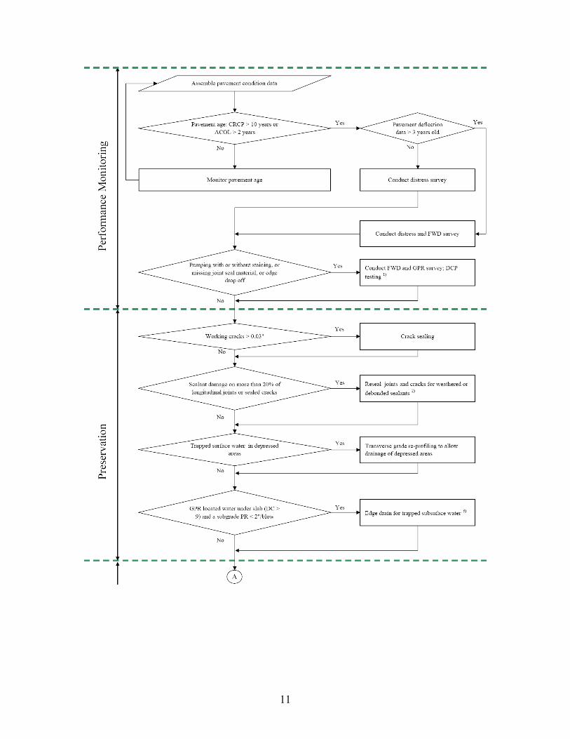
3. REPAIR DECISION FLOWCHART FOR ROUTINE MAINTENANCE Based on the pavement condition evaluation, the following decision flowchart provides guidance for effective routine maintenance. The decision flowchart is self explanatory.

10
Figure 4 AC/Non AC Overlaid JC Pavement Routine Maintenance Decision Flowchart.
11

12
Figure 5 AC/Non AC Overlaid CRC Pavement Routine Maintenance Decision Flowchart.

13
4. DETAIL SHEETS This chapter introduces the detail plans of current concrete pavement repair methods using state DOTs and the American Concrete Pavement Association (ACPA) to provide various applications for routine maintenance. The original plans of DOTs used in this chapter are attached in Appendix B and special specifications are attached in Appendix C. Step by step repair procedure and materials for each repair type are not provided because many well established manuals are available from various sources and are listed as references. For instance, a good source from FHWA, “Pavement Preservation Checklist Series” could be downloaded from the web address, <http://www.fhwa.dot.gov/pavement/preservation/ppcl00.cfm>. 4.1. SEAL JOINT AND CRACKS Joint and crack sealing is a basic precaution taken against development of significant distress in concrete pavement. Maintaining joint and crack sealing is important to minimize water and incompressible materials infiltration into the joint and potential subgrade softening/pumping or spalling of the joint (3). The longitudinal joint is particularly important to maintain since extensive amounts of surface water can enter at the lane/shoulder joints.
Figure 6 shows joint seal repair details of the Georgia Department of Transportation (DOT) (4). It notes that the backer rod is to be oversized to fit into the existing joint and be compressed enough to resist movement during the sealing operation. Figure 7 shows joint seal repair details of California DOT for various joint widths (5). Joint well repair is required if joint width is wider than 1 in., multiple resealing operations may require repair of the joint well.
Figure 6 Details for Resealing Joints (4).
14
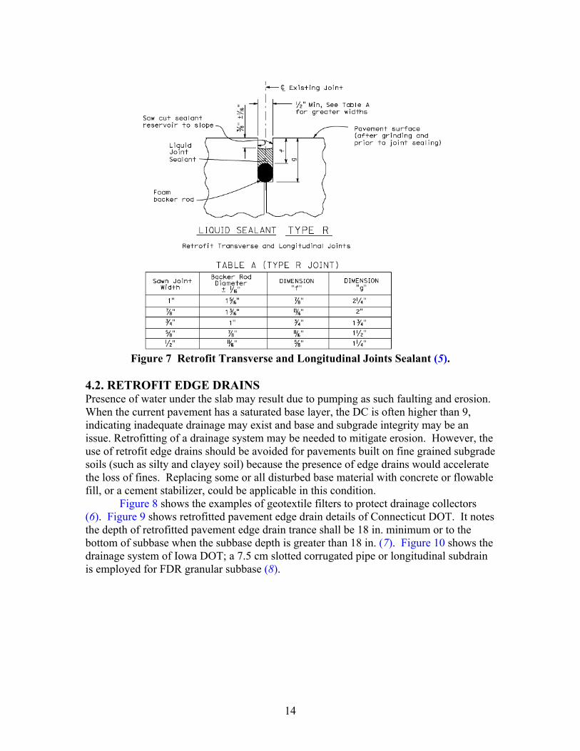
Figure 7 Retrofit Transverse and Longitudinal Joints Sealant (5).
4.2. RETROFIT EDGE DRAINS Presence of water under the slab may result due to pumping as such faulting and erosion. When the current pavement has a saturated base layer, the DC is often higher than 9, indicating inadequate drainage may exist and base and subgrade integrity may be an issue. Retrofitting of a drainage system may be needed to mitigate erosion. However, the use of retrofit edge drains should be avoided for pavements built on fine grained subgrade soils (such as silty and clayey soil) because the presence of edge drains would accelerate the loss of fines. Replacing some or all disturbed base material with concrete or flowable fill, or a cement stabilizer, could be applicable in this condition.
Figure 8 shows the examples of geotextile filters to protect drainage collectors (6). Figure 9 shows retrofitted pavement edge drain details of Connecticut DOT. It notes the depth of retrofitted pavement edge drain trance shall be 18 in. minimum or to the bottom of subbase when the subbase depth is greater than 18 in. (7). Figure 10 shows the drainage system of Iowa DOT; a 7.5 cm slotted corrugated pipe or longitudinal subdrain is employed for FDR granular subbase (8).

15
Figure 8 Drainage Collector (6).
Figure 9 Retrofitted Pavement Edge Drain (7).
Figure 10 Subdrain System (8).

16
4.3. PARTIAL DEPTH REPAIR Partial depth repair restores localized surface distress in the upper third to half of a concrete slab due to distresses such as joint or crack spalling. When the deterioration is greater than half of the slab thickness or includes the reinforcing steel, a full depth repair should normally be employed however, in the case of a deep delamination, only the delaminated concrete is removed and replaced. Remove and clean the deteriorated concrete area first, and place new concrete to reform the joint system (9). Figures 11 and 12 show typical layouts for partial depth repairs. The following guidelines are recommended to determine the repair size by ACPA (6, 10).
• Use a minimum length of 12 in.
• Use a minimum width of 4 in.
• Extend the patch limits beyond the delamination marks or visible spalls by 3-4 in
• Do not place a patch if the spall is less than 6 in. long and less than 1.5 in. wide.
• If two patches will be less than 2 ft apart, combine them into one large patch.
• Repair the entire joint length if there are more than two spalls along a transverse joint.
Figure 11 Partial Depth Spall Repair (10).

17
Figure 12 Spall Repair (6).
Figure 13 shows details for patching PCC pavement as suggested by the Georgia
DOT (4). These details provide a visual explanation for the most patching situation; patching limits extend 2 in. beyond the distressed area which is less than ACPA’s recommendation.
Figure 13 Details for Patching PCC Pavement (4).

18
Figure 14 shows the repair works on US 59 near Leggett, Texas, accomplished 5
years ago where 2.4 miles of hot mixed asphalt (HMA) was milled off and the concrete pavement joints were repaired using two types of repair method as shown in the figures (11). After 5 years of service, the pavement condition is very good and there is no visible distress over the repair section. Hot mixed asphalt overlay needs to cool prior to compaction using fabric underseal in the repair because heat can damage fabric underseal.
Inside lane Outside lane
Unit repair cost: $ 7.26 /ft Unit repair cost: $ 2.17 /lb
Figure 14 US 59 Southbound Joint Repairs (11).
Figure 15 shows a proposed alternative partial depth repair strategy instead of full
depth repair for deep delamination (12). When spalling depth is around 1/2 the thickness of the slab up to the reinforcing steel, FDR is recommend as a typical repair method. However, if remaining slab is strong with no other distress and steel is not corroded, following proposed PDR method could be employed. Steel positions and quantities can be determined in the field by the project engineer.
PFC 1 ¼ ~ 1 ½ in.
Coat Surface Treat ¾ in.
Level up 1 ½ in.
PCC 8 in.
HMA 4 in.
PCC 8 in. PCC 8 in.
Milled HMA
Underseal or Fiber screed
Repair and overlay Crack by faulting

19
12~18 in.
12~18 in.
4 in.
4 in. 12~18 in.
OPTIONAL STEEL BAR
2~3 in.
1~11/2 in. DIA.
ROUNDED END
STEP 2
D
D/3
D/3
STEP 1
D
D/3
DRILL & EPOXY
12~18 in.
12~18 in.
4 in.
4 in. 12~18 in.
OPTIONAL STEEL BAR
2~3 in.
1~11/2 in. DIA.
ROUNDED END
STEP 2
D
D/3
D/3
STEP 1
D
D/3
12~18 in.
12~18 in.
4 in.
4 in. 12~18 in.
OPTIONAL STEEL BAR
2~3 in.
1~11/2 in. DIA.
ROUNDED END
STEP 2
D
D/3
D/3
STEP 1
D
D/3
DRILL & EPOXY
Figure 15 Alternative Repair Strategy to Full Depth Repair for Deep Delamination
(12). 4.4. DIAMOND GRINDING Diamond grinding removes a thin layer of surface concrete. This method improves ride quality by removing faulting, joint warping, and uneven surface of patching while decreasing noise level of the concrete surface. These ride quality improvements provide service life extension by reducing impact loadings and pumping at the joint or cracks. Diamond grinding is also an effective method to improve skid resistance. The ground pavement surface improves surface drainage by creating small longitudinal channels that drain water from underneath the tire and reducing the potential of hydroplaning. Diamond grinding is a cost-effective treatment and useful to provide a finished surface after other repairs have been made. Figure 16 shows the surface of diamond grinding and detail dimensions of grinding texture (13).
Figure 16 Diamond grinding (13).
20
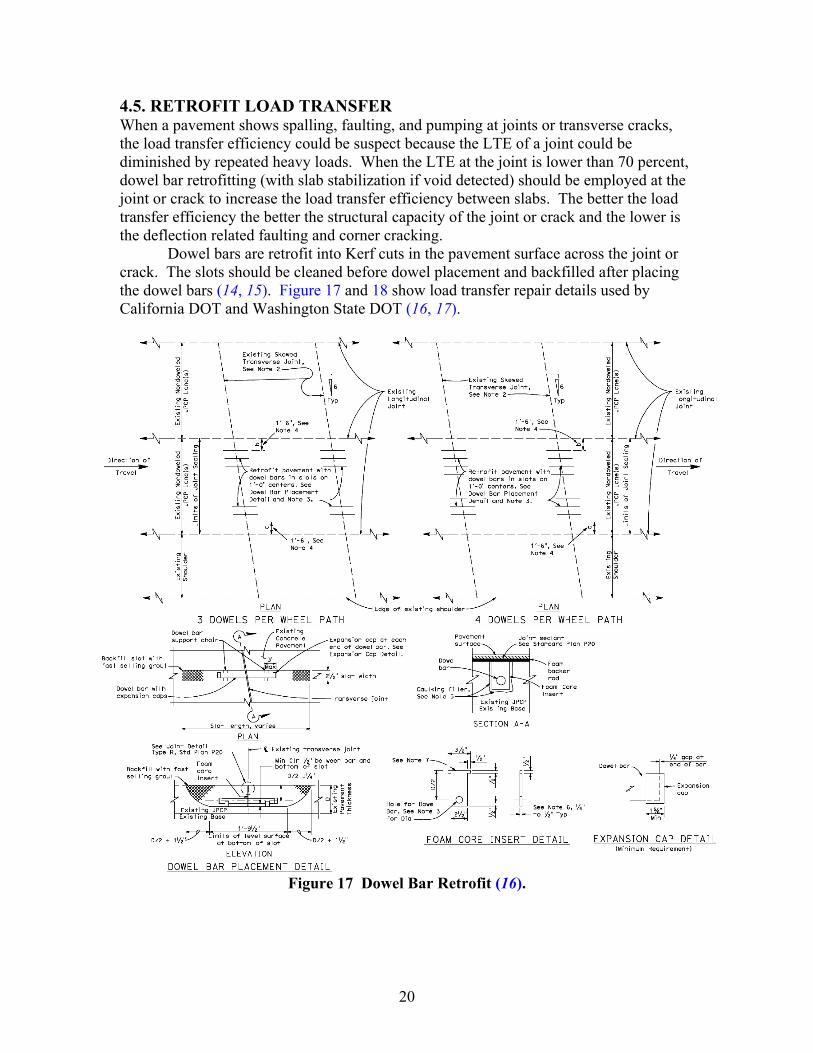
4.5. RETROFIT LOAD TRANSFER When a pavement shows spalling, faulting, and pumping at joints or transverse cracks, the load transfer efficiency could be suspect because the LTE of a joint could be diminished by repeated heavy loads. When the LTE at the joint is lower than 70 percent, dowel bar retrofitting (with slab stabilization if void detected) should be employed at the joint or crack to increase the load transfer efficiency between slabs. The better the load transfer efficiency the better the structural capacity of the joint or crack and the lower is the deflection related faulting and corner cracking.
Dowel bars are retrofit into Kerf cuts in the pavement surface across the joint or crack. The slots should be cleaned before dowel placement and backfilled after placing the dowel bars (14, 15). Figure 17 and 18 show load transfer repair details used by California DOT and Washington State DOT (16, 17).
Figure 17 Dowel Bar Retrofit (16).

21
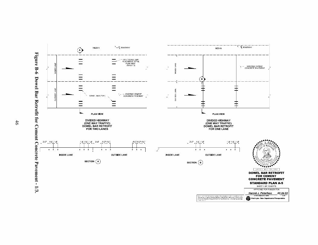
Figure 18 Dowel Bar Retrofit (17).

22
4.6. CROSS STITCHING Cross stitching could be employed instead of retrofit tie bars to repair longitudinal cracks or shoulder joint separation that are in a low severity condition (cross stitching is not appropriate for severely deteriorated cracks). Cross stitching uses # 6 deformed tie bars across a crack or shoulder joint. The tie bars space at 20-30 in. centers and alternate from side to side and are drilled across the crack at angles of 35º. Cross stitching limits the horizontal and vertical movement and prevents crack and joint widening by holding the crack together tightly using the steel reinforcement while increasing load transfer efficiency. Figure 19 shows the cross stitching detail for longitudinal crack or shoulder joint separation (18).
Figure 19 Cross stitching (18).
4.7. SLAB UNDERSEALING Slab undersealing could be used as a maintenance repair method when current patch or adjacent pavements have voids under slab. The injected material ideally should displace water from the voids and fill the voids under the slab without raising the slab. During the injection process, any upward movement of the slab needs to be detected to ensure that the slab is not raised. Faulting between two slabs could be eliminated using grinding after slab stabilization.
Figure 20 shows the concept of slab undersealing. The most common injection hole pattern is in the wheel path as shown in the Figure 20; sufficient holes are needed to permit grout to reach all voids beneath the pavement. The FWD can be used to detect voids under the slab but GPR testing is often necessary in advance to locate holes in a way that will ensure good grout distribution and void filling (6, 19).

23
Figure 20 Slab Undersealing by Grout Injection (6, 19).
4.8. FULL DEPTH REPAIR Full depth repairs involve replacing a portion of slab with new concrete. When other maintenance repair methods are not appropriate, full depth repair must be employed. When repair boundaries are decided, sawcut boundaries delineate where the old concrete would be removed before placing with new concrete. Each repair must be large enough to minimize future problems minimizing the patching material. Patching width is normally the same as the lane width but often half a lane width is recommended.
After the old concrete material has been removed, the base course should be examined and all of the disturbed material removed and the patch area recompacted. Replacing some or all disturbed base material (modulus is less than 10 ksi based on backcalculation of DCP testing or PR is higher than 1 in./blow) with concrete or flowable fill may be the best alternative since it is difficult to adequately compact granular material inside a patch. If proper compaction is not achieved, the base will settle and a void will develop under the slab.
If an untreated base contains a high percentage of fines (30 to 40 percent) and wet conditions, the modulus and general performance could be improved by adding low levels (2 to 4 percent) of cement stabilizer. This cement stabilizer would also be effective in improving wet subgrade soils. However, if excessive moisture exists in the repair area, it should be removed or dried before replacing. Grinding after FDR is necessary to remove uneven surfaces after patching which may improve ride quality and extend service life by reducing impact loadings at the joint.
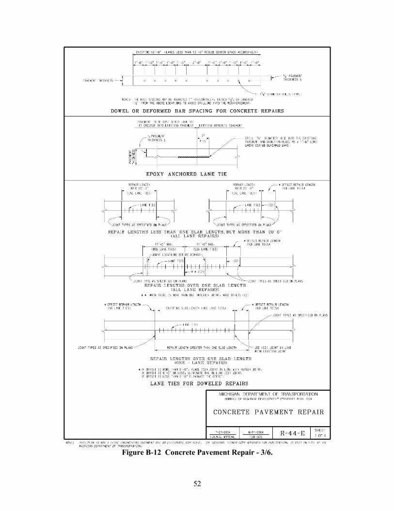
Figure 21 shows the patching patterns and general idea of the transverse and longitudinal joint type in various PCC pavement repair configurations (20). Figure 22 shows full depth repair detail used by the Texas DOT and Figure 23 shows tied and contraction joint detail for full depth repair used by the Michigan DOT (21, 22).

24
Figure 21 Full Depth Repair Layouts and Joint Types (20).
TABLETABLE
Figure 22 Full Depth Repair (21).

25
Figure 23 Joint Details for Repair (22).

26
Figure 24 shows three different types of reinforcing steel splice for CRC pavement (20). Each type has different lap splice length and offset distance between full and partial depth sawcut for protecting the perimeters of repair area. Figure 25 shows the repair detail for CRC pavement with tied steel splice detail used by the Michigan DOT (22).
Figure 24 CRC Pavement Full Depth Repair (20).
Figure 25 Repairing Detail for CRC Pavement (22).

27
Figure 26 shows snapshots of full depth repair using precast concrete slab which can reduce lane closure time by eliminating curing time. It can also expect a higher quality of concrete and less impacts from built-in curl (23).
(a) Precast PCC panel (b) Slab removal
(c) Dowel slots (d) Flowable fill
(e) PCC panel Installation (f) Finishing
Figure 26 Precast Concrete Slabs as Full-Depth Repairs (23).


29
REFERENCES
1. Hoerner, T. E., K. D. Smith, H. T. Yu, D. G. Peshkin, and M. J. Wade. “PCC Pavement Evaluation and Rehabilitation,” Reference Manual, NHI Course 131062. National Highway Institute, Arlington, VA, 2001.
2. Zollinger, D.G., S.D. Tayabji, and K.D. Smith. “Repair and Rehabilitation of Concrete Pavements, Volume II: Guidelines for Pavement Condition Assessment and Evaluation,” Report FHWA-RD-03-R-00XYZ. FHWA, U.S. Department of Transportation, 2003.
3. “Joint and Crack Sealing and Repair for Concrete Pavements,” TB012P, American Concrete Pavement Association, Skokie, IL, 1995.
4. “Resealing Joints in PCC Concrete Pavement & Bridge Deck Patching PCC Concrete Pavement,” Construction Details P-3, State of Georgia Department of Transportation, GA, September 1998.
5. “Concrete Pavement – Joint Details,” 2006 Standard Plan P20, State of California Department of Transportation, CA, May 2006.
6. “Concrete Pavement Repair Manual,” JP0002P, American Concrete Pavement Association, Skokie, IL, 2003.
7. “Underdrain and Outlets Pavement Edge Drain,” Standard Plan, Connecticut Department of Transportation, CT, August 1991.
8. “Full Depth PCC Patch with Dowels (Existing Non-Composite Pavement),” Standard Road Plan: Pavements Rehabilitation RR-4, Iowa Department of Transportation, IA, 2007.
9. “Concrete Crack and Partial-Depth Spall Repair Manual,” JP003P, American Concrete Pavement Association, Skokie, IL, 2004.
10. “Guidelines for Partial-Depth Spall Repair,” TB003P, American Concrete Pavement Association, Skokie, IL, 1998.
11. “Transverse Joint Repair Detail,” Plans of Proposed State Highway Improvement, Project No. C176-5-145, Texas Department of Transportation Lufkin District, TX, April 2003.
12. Won, Moonchul. “Alternative Repair Strategy to Full Depth Repair for Deep Delamination,” Technical Conversation, Center for Transportation Research, Austin, TX, February 2008.
13. “Diamond Grinding and Concrete Pavement Restoration,” TB008P, American Concrete Pavement Association, Skokie, IL, 2000.

30
14. “Concrete Pavement Rehabilitation: Guide for Load Transfer Restoration,” JP0001P, American Concrete Pavement Association, Skokie, IL, 1998.
15. “Specification Guideline for Dowel Bar Retrofit,” IS104P, American Concrete Pavement Association, Skokie, IL, 2002.
16. “Dowel Bar Retrofit (Existing Jointed Plain Concrete Pavement),” 2006 Standard Plan P7, State of California Department of Transportation, CA, May 2006.
17. “Dowel Bar Retrofit for Cement Concrete Pavement,” Standard Plan A-5, Washington State Department of Transportation, WA, February 2003.
18. “Stitching Concrete Pavement Cracks and Joints,” SR903P, American Concrete Pavement Association, Skokie, IL, 2001.
19. “Longitudinal Crack Repair,” Maintenance Design, Project US 290, Project No. CPM 50-9-62, Texas Department of Transportation Houston District, TX, November 2004.
20. “Slab Stabilization Guidelines for Concrete Pavements,” TB018P, American Concrete Pavement Association, Skokie, IL, 1994.
21. “Guidelines for Full-Depth Repair,” TB002P, American Concrete Pavement Association, Skokie, IL, 1995.
22. “Full Depth Repair for Concrete Pavement,” Roadway Standards: Pavements FDRCP-05, Texas Department of Transportation, TX, September 1994.
23. “Concrete Pavement Repair,” Standard Road Plans R-44-E, Michigan Department of Transportation, MI, October 2004.
24. Buch, Neeraj, V. Barnhart, and R. Kowli. “Precast Concrete Slabs as Full-Depth Repairs: Michigan Experience,” Transportation Research Record, Journal of the Transportation Research Board 1823, Washington, D.C., 2003, pp. 55-63.

31
APPENDIX A: CONDITION SURVEY FORM FOR ROUTINE MAINTENANCE


33
LIST OF TABLES
Page
Table A-1 JC Pavement Condition Survey Form for Routine Maintenance. .................. 35
Table A-2 CRC Pavement Condition Survey Form for Routine Maintenance. .............. 36


35
Table A-1 JC Pavement Condition Survey Form for Routine Maintenance. No. Check list Notes Further
inspection
1 Pavement age (yr.)
2 Aggregate type (hard or soft)
3 Year of recent pavement distress survey (yr.)
4 Year of recent pavement deflection survey (yr.)
5 Joint sealant age (yr.)
6 Sealant damage of transverse joint (%)
7 Sealant damage of longitudinal joint (%)
8 Sealant damage of sealed crack (%)
9 Trapped surface water in depressed area
10 Standing water or slab staining GPR, DCP
11 Pumping with or without staining GPR, DCP
12 Bump (stable or unstable, depth, in.) GPR, DCP
13 Settlement (stable or unstable, depth, in.) GPR, DCP
14 Joint spall (width, depth, % of joint spall > 2 in.) FWD
15 Crack spall (width, depth, % of crack spall > 2 in.) FWD
16 Deep spall (depth, in.) FWD, GPR, DCP
17 Patching (number/mile) FWD, GPR, DCP
18 Faulting (depth, in.) FWD, GPR, DCP
19 Transverse crack (width, number/slab) FWD, GPR, DCP
20 Longitudinal crack (width, number/slab) FWD, GPR, DCP
21 Shoulder separation (width, in.) FWD, GPR, DCP
22 Corner break (spall width, fault depth, % of slab) FWD, GPR, DCP
23 Reflection crack in ACOL (spall width, fault depth, number/mile) FWD, GPR, DCP
36
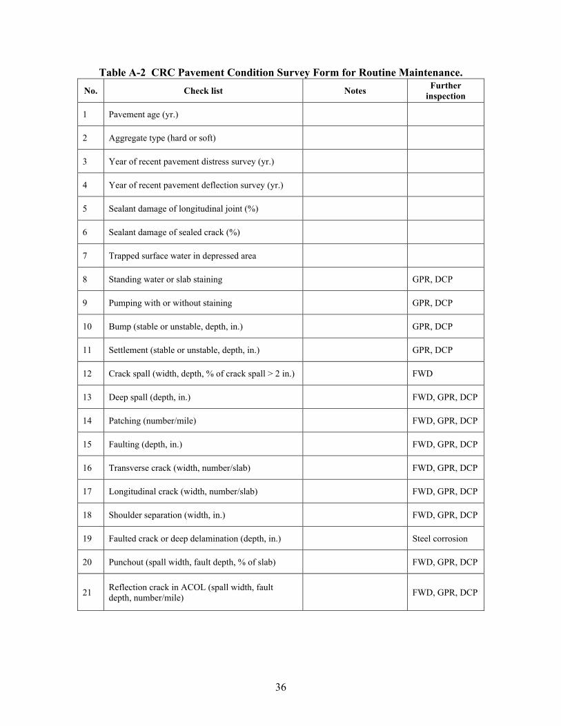
Table A-2 CRC Pavement Condition Survey Form for Routine Maintenance. No. Check list Notes Further
inspection
1 Pavement age (yr.)
2 Aggregate type (hard or soft)
3 Year of recent pavement distress survey (yr.)
4 Year of recent pavement deflection survey (yr.)
5 Sealant damage of longitudinal joint (%)
6 Sealant damage of sealed crack (%)
7 Trapped surface water in depressed area
8 Standing water or slab staining GPR, DCP
9 Pumping with or without staining GPR, DCP
10 Bump (stable or unstable, depth, in.) GPR, DCP
11 Settlement (stable or unstable, depth, in.) GPR, DCP
12 Crack spall (width, depth, % of crack spall > 2 in.) FWD
13 Deep spall (depth, in.) FWD, GPR, DCP
14 Patching (number/mile) FWD, GPR, DCP
15 Faulting (depth, in.) FWD, GPR, DCP
16 Transverse crack (width, number/slab) FWD, GPR, DCP
17 Longitudinal crack (width, number/slab) FWD, GPR, DCP
18 Shoulder separation (width, in.) FWD, GPR, DCP
19 Faulted crack or deep delamination (depth, in.) Steel corrosion
20 Punchout (spall width, fault depth, % of slab) FWD, GPR, DCP
21 Reflection crack in ACOL (spall width, fault depth, number/mile) FWD, GPR, DCP
37
APPENDIX B: REPRESENTATIVE STANDARD PLANS FOR ROUTINE MAINTENANCE OF STATE DOTS


39
LIST OF FIGURES
Page Figure B-1 Resealing Joints in PCC Concrete Pavement & Bridge Deck Patching PCC
Concrete Pavement. ..................................................................................................... 41
Figure B-2 Concrete Pavement – Joint Details................................................................ 42
Figure B-3 Underdrain and Outlets Pavement Edge Drain. ............................................ 43
Figure B-4 Full Depth PCC Patch with Dowels (Existing Non-Composite Pavement).. 44
Figure B-5 Dowel Bar Retrofit (Existing Jointed Plain Concrete Pavement). ................ 45
Figure B-6 Dowel Bar Retrofit for Cement Concrete Pavement - 1/3. ........................... 46
Figure B-7 Dowel Bar Retrofit for Cement Concrete Pavement - 2/3. ........................... 47
Figure B-8 Dowel Bar Retrofit for Cement Concrete Pavement - 3/3. ........................... 48
Figure B-9 Full Depth Repair for Concrete Pavement. ................................................... 49
Figure B-10 Concrete Pavement Repair - 1/6.................................................................. 50
Figure B-11 Concrete Pavement Repair - 2/6.................................................................. 51
Figure B-12 Concrete Pavement Repair - 3/6.................................................................. 52
Figure B-13 Concrete Pavement Repair - 4/6.................................................................. 53
Figure B-14 Concrete Pavement Repair - 5/6.................................................................. 54
Figure B-15 Concrete Pavement Repair - 6/6.................................................................. 55


41
Figure B
-1 Resealing Joints in PC
C C
oncrete Pavement &
Bridge D
eck Patching PC
C C
oncrete Pavement.

42
Figure B
-2 Concrete Pavem
ent – Joint Details.

43
Figure B
-3 Underdrain and O
utlets Pavement E
dge Drain.

44
Figure B
-4 Full Depth PC
C Patch w
ith Dow
els (Existing N
on-Com
posite Pavem
ent).

45
Figure B
-5 Dow
el Bar R
etrofit (Existing Jointed Plain C
oncrete Pavement).
46
Figure B
-6 Dow
el Bar R
etrofit for Cem
ent Concrete Pavem
ent - 1/3.

47
Figure B
-7 Dow
el Bar R
etrofit for Cem
ent Concrete Pavem
ent - 2/3.

48
Figure B
-8 Dow
el Bar R
etrofit for Cem
ent Concrete Pavem
ent - 3/3.

49
Figure B
-9 Full Depth R
epair for Concrete Pavem
ent.

50
Figure B-10 Concrete Pavement Repair - 1/6.

51
Figure B-11 Concrete Pavement Repair - 2/6.
52
Figure B-12 Concrete Pavement Repair - 3/6.

53
Figure B-13 Concrete Pavement Repair - 4/6.

54
Figure B-14 Concrete Pavement Repair - 5/6.

55
Figure B-15 Concrete Pavement Repair - 6/6.


57
APPENDIX C: SPECIAL SPECIFICATIONS FOR ROUTINE MAINTENANCE REPAIRS


59
TABLE OF CONTENTS
Page
RESEAL JOINTS AND CRACKS .................................................................................. 61
EDGE DRAIN .................................................................................................................. 67
PARTIAL DEPTH REPAIR............................................................................................. 71
DIAMOND GRINDING .................................................................................................. 77
RETROFIT LOAD TRANSFER...................................................................................... 81
CROSS STITCHING........................................................................................................ 85
FULL DEPTH REPAIR ................................................................................................... 87


61
SPECIAL SPECIFICATION
RESEAL JOINTS AND CRACKS
DESCRIPTION
This work includes removing the existing sealant material (if applicable), cleaning the joint, and installing silicone sealant in the roadway and bridge joints specified on the plans. The plans will designate the type of joint (transverse or longitudinal), location of joint (mainline, shoulder, ramps, acceleration/deceleration lanes), type of joint (roadway, bridge) to be resealed, which type silicone to use (Type A, B, C, or D). The Engineer will determine the roadway and bridge cracks to be resealed. Unless otherwise specified on the plans, use Type A silicone for roadway joints and use Type D silicone for bridge joints.
MATERIALS
Silicone Sealant and Bond Breakers: Furnish silicone sealant in a one-part or two-part silicone formulation. Use sealant that is compatible with the surface to which it is applied. Do not use acid-cure sealants on Portland cement concrete.
1. Type A: A one part, low modulus, non-sag silicone. Used to seal horizontal and vertical joints in Portland cement concrete pavements and bridges. Tooling is required.
2. Type B: A one part, very low modulus, self-leveling silicone. Used to seal horizontal joints in Portland cement concrete pavements and bridges. Tooling is not normally required.
3. Type C: A one part, ultra-low modulus, self-leveling silicone. Used to seal horizontal joints in Portland cement concrete pavements and bridges and joints between Portland cement concrete pavement and asphaltic concrete shoulders. Tooling is not normally required.
4. Type D: A two part, ultra low modulus, self-leveling, rapid cure silicone. Used to seal horizontal joints in Portland cement concrete pavements and bridges and joints between Portland cement concrete pavement and asphaltic concrete shoulders. Tooling is not required.
Bond Breakers: Bond breakers shall be chemically inert and resistant to oils, gasoline, solvents, and primer, if one is required. Install silicone sealants over a bond breaker to prevent the sealant from bonding to the bottom of the joint.
Epoxy Resin Adhesives: Furnish the epoxy adhesive as two separate components.

62
EQUIPMENT
Air Compressors: Use air compressors equipped with traps to remove surplus water and oil in the compressed air. Do not use contaminated air. Ensure that the compressor can deliver compressed air at a continuous pressure of at least 90 psi (600 kPa). The Engineer may check the compressed air for contamination.
Silicone Sealant Pump: Apply silicone sealant by pumping only. Use a caulking gun with a cartridge for touch-up work or small applications only. Use a pump with sufficient capacity to deliver the necessary volume of silicone to completely fill the joint in a single pass. Ensure that the nozzle’s size and shape closely fits into the joint to fill the joint with sealant using enough force to prevent voids in the sealant and to force the sealant to contact the joint faces.
Caulking Gun: Use a caulking gun with cartridge for the following situations: (a) Touch up work; (b) Placing vertical runs of Type A silicone in a bridge deck joint when Type B, C, or D silicone is used in the horizontal runs; (c) Sealing voids and cracks with Type A silicone where Type B, C, or D silicone (which will be applied on top of the Type A silicone) might leak through; and (d) Sealing small cracks in the concrete.
CONSTRUCTION METHODS
A. Preparation
Before installing a bond breaker or sealant, ensure that the joint is clean and dry. Complete all cleaning, air blasting, or air drying.
B. Resealing Existing Joints
1. Remove Existing Sealant
Completely remove the existing sealant in the joints. Take care during removal and cleaning to prevent damaging or enlarging the existing width of the joint. Repair any damaged areas at no cost to the Department.
2. Depth of Existing Joint
Determine if the joint depth will accommodate the required sealant thickness and bond breaker and provide the required recess below the riding surface.
Consider that the backer rod is thicker after it is squeezed into the joint.
If necessary, saw the existing joint deeper and wider to provide the joint depth and width specified on the plans.
3. Clean the Joint
63
Thoroughly clean the joint of all foreign material including oil, asphalt, curing compound, sealant adhesive, paint, rust, and existing sealant, if still present. Demonstrate to the Engineer that the proposed method of cleaning old sealant or foreign material from joints will not widen the joints by more than 0.040 in. (1 mm). The method shall not alter the joint profile (including rounding of the top corner) or alter the texture of the concrete riding surface. Do not use chemical agents to clean the joint. Ensure that the cleaning process produces a new, clean concrete face on the vertical faces of the joint.
C. Sealing New Joints
1. Sawing
Saw the transverse and longitudinal joints according to the Specifications and plan details.
a. Make the initial cut and wait for the concrete to harden enough to prevent spalling or raveling.
b. Make the second cut to the width and depth shown on the plans.
c. Do not use a gang saw to make a completed cut in a single operation.
d. If spalling of the sawed edge harms the joint seal, patch the spall with an approved epoxy patching compound and allow it to fully cure before installing the joint sealant.
e. Make each patch to the intended neat lines of the finished cut joint.
2. Cleaning Freshly Cut Sawed Joints
Immediately after sawing the joint do the following:
a. Completely remove the resulting slurry from the joint and clean the immediate area by flushing it with a jet of water under pressure. Use other tools as necessary.
b. When the surfaces are thoroughly clean and dry and immediately before placing the joint sealer, use compressed air with a pressure of at least 90 psi (620 kPa) to blow out the joint and remove dust traces.
c. If freshly cut sawed joints are contaminated before they are sealed, clean them before seal.
d. Ensure that cleaning methods do not alter the joint profile, the rounding of the top corners, or the concrete riding surface texture. Do not clean the joint with chemical agents.

64
D. Sealing Joints
1. Install Bond Breakers
Select and use bond breakers [backer rod (if required) or tape] according to the following:
a. Before installing a bond breaker, clean and dry the joint or crack. Before placing the bond breaker and sealant, complete the cleaning, air blasting, or air drying.
b. Ensure that the backer rod diameter is at least 25 percent larger than the joint width.
c. Install the backer rod in the joint at the depth specified on the joint detail in the plans, as directed by the Engineer.
d. The width of some bridge joints may require back-up material other than the typically shaped round backer rod.
e. Use material available in square or rectangular shapes, or cut the strips from sheet stock to fit properly into the joint. Use approved bond breaking tapes in place of backer rod in some applications. See plan details for various joint types.
2. Install Silicone Sealant
Install the silicone sealant immediately after cleaning the joint or crack and installing the bond breaker. Keep the joint or crack clean and dry.
If the joint or crack becomes contaminated, damp, or wet, remove the bond breaker if it has been installed. Clean and dry the joint or crack and install a new bond breaker before placing the sealant.
Follow these guidelines when placing the sealant:
a. Ensure that the air temperature during placement is at least 40 ºF (4 ºC).
b. Use a pump to apply the silicone sealant. The pump must be able to completely fill the joint to the specified width and height of sealant in one pass. Use a nozzle with the proper size and shape to closely fit inside the joint. The sealant must be introduced inside the joint with enough pressure to prevent voids in the sealant and to force the sealant into contact with the joint faces.
c. Use a caulking gun with cartridge for touch-up work, small applications (such as vertical runs with Type A silicone in a bridge deck joint when Type B, C, or D silicone is used), and to seal voids and cracks with Type A silicone

65
where Type B, C, or D silicone might leak through. You may also use a caulking gun to seal small cracks in the concrete.
d. After placing Type A silicone sealant, tool it to provide the specified recess, thickness, and shape as shown on the plans. Apply sufficient force to the sealant in this tooling operation to force the sealant against the joint faces and to ensure proper wetting and bonding of the sealant to the joint faces. Type B, C, and D silicones are self-leveling and do not normally require tooling.
e. Because of the consistency of Type B, C, and D silicones, ensure that the bond breaker completely closes off gaps and voids where the silicone might leak through. To ensure that the gaps are closed use any of the following methods:
• Stuff small pieces of backer rod into the gaps and voids.
• Place a piece of bond breaking tape over the void.
• Use Type A silicone to seal the void.
If using Type B, C, or D silicone and a backer rod, ensure the backer rod is Type M. Do not use Type L backer rod with Type B, C, and D silicone.
f. Place the sealant to conform to the specified recess and thickness shown in the plans.
3. Clean Pavement
After sealing a joint or crack, immediately remove the surplus sealant or other residue on the pavement or structure surfaces.
4. Open to Traffic
Do not permit traffic on the sealed joints or cracks until:
• The sealant is tack free.
• The sealant has cured enough to resist displacement from slab movement or other causes.
• Debris from traffic does not imbed into the sealant.
5. Special Requirements
The following requirements apply to this work:
a. Seal the joints and cracks for any one day’s work on resealing projects within 30 calendar days after surface grinding for that day is completed, unless otherwise specified in the plans. Seal joints on new pavement after the curing

66
period. When the plans call for resealing before specified grinding, increase the recess depth and joint depth by 1/4 to 3/8 in. (6 to 10 mm) to compensate for the depth of the pavement removed during the grinding operation.
b. The Engineer will determine all cracks to be resealed.
c. Route cracks to the depth specified on the plans by wet or dry sawing with diamond or abrasive blades. Remove sawing residue or other contaminants.
d. If the manufacturer recommends a primer, use it according to the recommendations. When required, install primer before the backup material.
e. Seal the bridge joints, including the approach slab, specified on the plans. Only reseal non-armored joints (one-sealant receptacle and concrete surfaces on joint faces), unless otherwise indicated on the plans.
MEASUREMENT
When listed as a pay item in the Proposal, joints and cracks sealed and resealed will be measured in linear feet (meters).
No separate measurement and payment will be made unless a pay item for the work is included in the Proposal. If no pay item is included in the Proposal, include the cost of the joint sealing and resealing in the overall bid price submitted.
No separate measurement or payment will be made for any sawcutting required to seal or reseal the joint.
PAYMENT
When listed as a pay item in the Proposal, joints and cracks sealed or resealed will be paid for at the Contract Unit Price bid per linear ft (meter). Payment is full compensation for furnishing materials, equipment, tools, labor, and incidentals to complete the work.

67
SPECIAL SPECIFICATION
EDGE DRAIN
DESCRIPTION
This work consists of furnishing and installing an approved Prefabricated Geocomposite Edge Drain (PGED) as specified at the location(s) and to the limits shown in the contract documents or as directed by the Engineer, in writing, prior to performing the work. This work includes excavating and backfilling the trench.
MATERIALS
A. General
Provide Geotextile and Prefabricated Geocomposite Edge Drain of the type appropriate for the intended use as shown on the plans and as listed in the appropriate Approved List issued by the Department’s Materials Bureau. Evaluation of a Geotextile or Prefabricated Geocomposite Edge Drain not on the Approved List will be made in accordance with procedural directives of the Geotechnical Engineering Bureau. Evaluation will require a minimum of four months.
Provide PGED that is a flexible product consisting of a geotextile bonded to or tightly wrapped around an internal supporting core.
Provide PGED that is resistant to deterioration from salts, road oils, fuels, and other deleterious substances encountered in the type of application.
B. Basis of Acceptance
Geotextiles: The Geotextiles which are on the Approved List issued by the Department’s Materials Bureau will be accepted on the basis of the brand name labeled on the Geotextile or the Geotextile container and verification of the Geotextile by a Departmental Geotechnical Engineer. Provide Drainage class geotextile conforming to apparent opening size (AOS) Class A, and Strength Class 2 or higher.
Prefabricated Geocomposite Edge Drain: The Prefabricated Geocomposite Edge Drains which are on the Approved List issued by the Department’s Materials Bureau will be accepted on the basis of the brand name labeled on the drain’s packaging and verification by the Engineer of the geotextile wrap being on the approved list for Drainage application for AOS Class A, and Strength Class 2 or higher.

68
C. Quality Assurance of Prefabricated Geocomposite Edge Drain
When the State elects, a one (1) meter long sample will be obtained for quality assurance testing. The results of this testing will only affect a product’s standing on the Approved List. No payment will be made for this sample.
D. Backfill Material
Provide backfill material meeting the following requirements:
For existing material backfill, provide suitable material.
For underdrain filter material backfill, provide material that meets the requirements of Underdrain Filter.
E. Fittings
Provide fittings and materials necessary to make splices and connections of the PGED to outlet piping that conform to the manufacturer’s requirements. Design all fittings and materials to prevent soil intrusion into the PGED or outlet piping.
Provide fittings that allow for outletting the continuous PGED in a sag area (ie., a tee) and for outletting the individual run length segments as shown in the contract documents or as ordered by the Engineer.
In cases where the PGED is terminated without an outlet, provide a fitting to prevent soil intrusion into the end of the PGED.
CONSTRUCTION METHODS
Excavate a trench in the location and to the limits shown in the contract documents or as directed by the Engineer.
Where existing material backfill is used, place the PGED abutting the side of the trench closest to the centerline of pavement (the inside of the trench). Where underdrain filter material backfill is used, place the PGED abutting the side of the trench farthest away from the centerline of pavement (the outside of the trench). Place the PGED in an upright vertical position so that it has no bends, crimps, or sags in its final position. Be aware that many PGED’s provide drainage on only one side. Place the PGED so the side that provides drainage faces the pavement.
Backfill and compact the trench. Where underdrain filter material backfill is used, place the backfill in one lift. Where existing material backfill is used, place backfill in approximately three equal lifts. For existing material backfill, perform the trenching, PGED placement, and first lift backfill and compaction operations in one continuous operation.

69
Compact each lift with at least two passes of an approved vibrating pad, plate, or drum-type compactor. Other vibratory compaction systems may be used as approved by the Engineer. Remove the surplus excavated material from the work area and dispose of it as required in disposal of surplus excavated materials.
For any given PGED run, install outlets no later than 48 hours after PGED placement. Do not backfill the outlet trench until the installation of the fitting and connection to the outlet pipe is inspected and approved by the Engineer. Backfill all trenches before the end of the workday.
Install splices required in the PGED prior to placement of the PGED. Install splices and connections in the PGED in accordance with the manufacturer’s recommendations to ensure continuity of the PGED.
During all periods of shipment and storage, keep the PGED wrapped and protected from direct exposure to sunlight, mud, dirt and debris. Repair or replace any damaged portion of the PGED to the satisfaction of the Engineer. Payment will not be made for repairing or replacing the damaged portions caused by the Contractor’s operations.
Backfill and compact all portions of the trench which are overcut in length to facilitate the operation of the trench cutting equipment in accordance with the same requirements as for the trench containing the installed PGED.
MEASUREMENT
The quantity of the PGED to be paid will be the number of linear meters satisfactorily installed computed from the payment lines indicated in the contact documents or from payment lines established, in writing, by the Engineer.
PAYMENT
The unit price bid per linear meter includes the cost of furnishing all labor, equipment and material necessary to satisfactorily complete the work, including excavation, installation, underdrain filter material, backfilling and compacting, repair of overcuts, and removal of surplus excavated material. Payment will not be made for repairs of damage caused by the Contractor’s operations.
Payment for outlets is not included and will be made under the appropriate, separate pay items.


71
SPECIAL SPECIFICATION
PARTIAL DEPTH REPAIR
DESCRIPTION
This work includes partial depth patching of spalls and potholes in Portland cement concrete pavement by removing the broken, damaged, or disintegrated concrete pavement. This work also includes removing asphaltic concrete patches from spalled or damaged areas of the pavement surfaces and patching them with approved patching materials according to this Specification and the existing pavement cross-sections.
MATERIALS
Ensure that the materials used to repair and patch Portland cement concrete pavement conform to the rapid setting patching material requirements.
The laboratory may waive the setting time requirements of approved materials if the minimum compressive strength development is unaffected.
EQUIPMENT
To clean the repair areas, use air compressors equipped with traps that can remove surplus water and oil in the compressed air. Ensure that the compressor can deliver compressed air at a continuous pressure of at least 90 psi (620 kPa).
The Engineer will check the compressed air daily for contamination. Do not use contaminated air.
CONSTRUCTION METHODS
A. Removing and Preparing the Repair Area
Prepare to perform partial patching of spalled joints and potholes as follows:
1. Partial Depth Patching of Spalled Joints
a. “Sound” each transverse joint and longitudinal joint with a visual defect to determine the limits of the damaged or defective areas. Strike the pavement surface along the sides of each joint with a hammer, chain drag, or similar tool to detect unsound concrete that sounds flat or hollow.
72
b. Mark the limits of the defective areas on the pavement by making a rectangle 2 in. (50 mm) beyond the outer limits of the unsound concrete area as a guide for sawing.
c. Mark spalled areas less than 2 ft (600 mm) from each other along a joint as one spall area. If separated by 2 ft (600 mm) or more, mark as separate spall areas.
Do not repair defective (spalled) joint areas less than 6 in. (150 mm) long and 1.5 in. (40 mm) wide under this Specification. Thoroughly clean and seal them with silicone sealant as part of the joint sealing operation.
d. Saw the rectangular marked areas with near vertical faces at least 2 in. (50 mm) but not more than 3 in. (75 mm) deep.
e. Remove unsound material within the sawed area with a maximum 30 lb (135 N) chipping hammer.
f. Do not damage or fracture the sound concrete substrate to be left on the bottom of the spall area. Do not use sharp pointed bits.
g. If the unsound material is more than 4 in. (100 mm) deep, the Engineer may direct a 6 ft (1.8 m) slab replacement be placed.
h. Before placing the patching material, saw the face of the existing transverse or longitudinal joints bordering the repair areas. Saw at least 5 in. (125 mm) deep and 0.25 in. (6 mm) wide with the full depth of the sawcut extending at least 1 in. (25 mm) beyond the limits of the repair areas in each direction.
i. Immediately before placing the patching material, thoroughly clean the surfaces within the repair areas by sandblasting and air blasting to remove oil, dust, dirt, traces of asphaltic concrete, slurry from saw operation, and other contaminants.
j. Place a 0.25 in. (6 mm) wide piece of closed cell polyethylene foam shaped to fit the sawcut in the joints bordering the repair areas.
If “back-to-back” repairs are made at a joint, support the 0.25 in. (6 mm) closed-cell polyethylene foam during the placing operation to maintain a true, straight joint line.
Have the Engineer approve the method used. The polyethylene foam must be supported in a straight line when the patching material is placed so a straight joint line will be formed.
Maintain a straight line or the Engineer may require the repairs be repeated at no additional cost to the Department.

73
2. Partial Depth Patching of Pavement Potholes
The Engineer will determine which pavement potholes will be repaired.
Use the procedures given for repairing spalled joints to repair potholes within the pavement surface. The requirement of using the 0.25 in. (6 mm) closed-cell polyethylene foam does not apply.
B. Concrete Patching
Patch concrete one lane at a time, safely and rapidly to minimize inconvenience to the traveling public.
1. Accomplish the work with other operations in progress within an area if possible.
2. Complete the work before the grinding operation begins, if grinding is specified.
3. Remove and replace completed concrete patches that contain cracks, shrinkage, compression failures, or are damaged by construction or traffic before Final Acceptance at no additional cost to the Department.
C. Placing Patching Material
Use Repair Method 1 unless the State Materials Research Engineer gives written approval to use Repair Method 2. Use Repair Method 1 when the average daily temperature is 50 ºF (10 ºC) or above. Use of Repair Method 2, if approved, is limited to the manufacturer’s written recommendations.
For the following repair methods, begin the placement when the surface within the repair area is dry and thoroughly free of contaminants.
Ensure that the finished surface including joints meets a surface tolerance of 1/8 in. (3 mm) per 10 ft (3 m).
Use approved measures as necessary to keep pavement surfaces adjacent to this operation free of excess grout and other materials. Unless otherwise specified, complete the patching operations and open the lanes to traffic before sunset each day.
1. Repair Method 1: Twenty-four Hour Accelerated Strength Concrete
Use this method as follows:
a. Completely coat the concrete surface areas within the repair area with a film of Type II epoxy approximately 10 to 20 mils (0.25 to 0.50 mm) thick.
b. Mix the concrete on-site in a portable mixer. Obtain approval for the mix design and mixing method from the laboratory. The material must meet a slump range of 1.0 in. (25 mm) to 3.0 in. (75 mm).

74
c. Deposit the concrete in the repair area while the epoxy is still tacky. Vibrate it to form a dense, homogeneous mass of concrete that completely fills the patch area.
d. Screed the concrete to the proper grade and do not disturb it until the water sheen disappears from the surface.
e. Cover the concrete with wet burlap or membrane curing compound. Allow the curing to continue for at least three hours. The Engineer may require longer curing to ensure sufficient concrete strength development before opening to traffic.
2. Repair Method 2: Rapid Setting Patching Material for Portland Cement Concrete Pavement
a. In addition to the requirements outlined in “Removing and Preparing the Repair Area,” prepare the surfaces in the repair areas according to the manufacturer’s written recommendations.
b. Perform the patching material handling, mixing, placing, consolidating, screeding, and curing according to the manufacturer’s written instructions as approved by the laboratory.
c. Continue curing for at least one hour and until opening the section to traffic.
D. Special Requirements
The following special requirements apply to this work:
1. If repairing adjacent to an unstable shoulder, place a form the full depth of the repair area to maintain a true, straight shoulder joint and to prevent the patching material from intruding onto the shoulder area.
2. After curing the patching material, remove the form and repair the shoulder at no cost to the Department.
3. During sandblasting, protect traffic in the adjacent lanes.
4. After the sandblasting operations:
a. Thoroughly clean the area to be repaired with compressed air.
b. Remove sand from the sandblasting operation from the roadway and shoulders.
5. Do not “over-cut” the pavement beyond marked areas whenever possible.
6. Remove saw slurry and other contaminates from the over-cutting.

75
7. Repair the over-cuts by filling full depth with an approved low-viscosity epoxy compound using a Type II epoxy adhesive. Make these repairs as soon as possible, but not after the joint is resealed.
8. Re-establish original transverse and longitudinal joints by sawing and sealing the joints with silicone that meets the requirements of the plan details. Re-establish the joints within 60 days after placing the patch. Ensure that re-established joints are at least 3/8 in. (10 mm) wide.
MEASUREMENT
The area measured for payment is the number of square yards (meters) of patching complete in place and accepted.
PAYMENT
The area measured as specified above will be paid for at the Contract Unit Price per square yard (meter). Payment is full compensation for equipment, tools, labor, incidentals to complete the work, including but not limited to:
• Removing existing asphaltic concrete patching material or the spalled, broken, or damaged Portland cement concrete;
• Cleaning the open area by sandblasting;
• Furnishing, placing, finishing, and curing the patching material; and
• Sawing and sealing new transverse and longitudinal joints.


77
SPECIAL SPECIFICATION
DIAMOND GRINDING
DESCRIPTION
This item shall govern for diamond grinding existing portland cement concrete pavement surfaces and the removal of the residue resulting from the grinding operations at locations designated on the plans or as directed by the Engineer and in accordance with the requirements herein.
EQUIPMENT
Grinding shall be done utilizing diamond blades, mounted on a multi-blade arbor on a self-propelled machine which has been built for grinding pavements. The equipment shall have sufficient power, traction, and stability to maintain accurate depth of cut and slope. The grinder shall have a depth control device which will detect variations in the pavement surface and adjust the cutting head height to maintain the depth of cut specified. The grinding machine will be equipped with devices to control alignment. Flailing grinding devices will not be permitted.
CONSTRUCTION METHODS
Grinding shall be performed in a longitudinal direction and shall begin and end at lines normal to the pavement lane lines. Grinding shall be terminated a minimum of 1 ft from bridge or approach slab expansion joints.
The grinding shall produce a uniform finished surface, eliminate joint or crack faults, and provide positive lateral surface drainage. Auxiliary or ramp lane grinding shall transition as required from the mainlane edge to maintain or provide positive lateral drainage and an acceptable riding surface.
Contractor shall perform grinding operations in such a manner as to limit spalling or partial depth failures. Repair of any damaged concrete pavement as a result of the Contractors operations shall be the responsibility of the Contractor. Repair shall be in accordance with Special Specification, “Concrete Repair of Spalls on Concrete Pavement” for spalls of 0 - 1.5 in. (0 - 38 mm) in depth. Repair of spalls greater than 1.5 in. (38 mm) shall be in accordance with Item 361, “Full Depth Repair of Concrete Pavement.”

78
Longitudinal grinding shall begin at the outside edge of the portland cement concrete pavement and run in a continuous pattern across the lane surface to the opposite outer edge of the traffic lane or pavement. The ground surface shall be uniform in appearance with a longitudinal corduroy type texture. The grooves shall be between 0.1 and 0.15 in. (2.5 and 3.5 mm) wide. The land area between the grooves shall be between 0.07 and 0.08 in. (1.7 and 2.0 mm). The width of the groove shall have a tolerance of plus or minus 0.02 in. (0.5 mm) under normal pavement conditions. On curve and/or super elevated areas, the width of the grooves may exceed this tolerance.
The depth of the grooves shall have a tolerance of plus or minus 0.06 in. (1.5 mm).
At the beginning of each work shift, all grinding machines shall be equipped with a full complement of grinding blades that are capable of cutting grooves of the specified width, depth and spacing.
Grinding shall provide a positive lateral drainage by maintaining a constant cross slope across each lane. The entire area designated on the plans shall be textured and surfaces on both sides of the transverse joints or cracks shall be in essentially the same plane, in accordance with smoothness specifications. However, extra depth grinding to eliminate minor depressions is not required.
The actual ground area of any 3 ft (1 m) by 100 ft (30 m) selected longitudinal area of pavement specified to be ground shall not be less than ninety percent (90 percent) of the selected longitudinal area. Any 3 ft X 100 ft (1 m X 30 m) section not meeting this requirement will not be measured for payment.
The ground pavement shall meet a surface tolerance at least as stringent as that described in the Special Specification Item 5000 “Ride Quality for Pavement Surfaces” under “Testing Procedures, Surface Test Type B”. The pavement surface shall be measured for riding quality using a multiple wheel profilograph. The pavement is to be evaluated in 525 ft (160 m) sections. The profile index shall not exceed 10 in. per mile (150 mm per km). A unit price adjustment may be used for a profile index of 10 in. to 15 in. per mile (150 mm to 240 mm per km) in lieu of re-grinding to meet the 10 in. per mile (150 mm per km) criterion. No payment will be made for a profile index in excess of 15 in. per mile (240 mm per km).
A straight edge requirement may be used to control bumps and/or ridges in pavement surface. Grinding along the inside of existing pavement shall conform to the above referenced Item 5000. Straightedge requirements do not apply across longitudinal joints or outside the ground areas. The transverse slope of the pavement shall be uniform to a degree that there shall be no depressions or misalignment of slope greater than 0.1 in. (3 mm) between passes of the cutting head when tested by stringline or straight edge placed perpendicular to the centerline. Transverse joints and random cracks shall be visually inspected to ensure that adjacent surfaces are in the same plane. Misalignment of the planes of these surfaces shall not exceed 0.02 in. in 1 ft (1.5 mm in 1 m).

79
The removal of all slurry or residue resulting from the grinding operation shall be continuous. Pavement must be immediately left in a washed clean condition, free of all slipperiness from the slurry, etc. Residue from grinding operations should not be permitted to flow across shoulders or lanes occupied by public traffic or to flow into gutters or other drainage facilities. Solid residue, resulting from grinding operations, should be removed from the pavement surfaces before such residue is blown by the action of traffic or wind.
The Department will take random samples of the grinding residue and cooling water for chemical testing. The contractor shall allow access for department personnel to obtain the samples.
All joint restoration work (except sealing) shall be completed prior to the diamond grinding operation. All sealing of joints shall be completed after the grinding operation. MEASUREMENT
This item will be measured by the square ft (m) of surface area ground, of the depth specified. Square ft (m) calculations will be based on the neat dimensions shown on the plans.
PAYMENT
The work performed and materials furnished in accordance with this Item and measured as provided under “MEASUREMENT” will be paid for at the unit price bid for “DIAMOND GRINDING CONCRETE PAVEMENT”, of the depth specified. This price shall be full compensation for grinding the pavement surface, repairing of damaged concrete pavement including spalls or partial depth failures, loading, hauling and disposing of the residue material, labor, tools, equipment, manipulation, and incidentals to complete the work.
No payment will be made for work done by any machine on a trial run to demonstrate its ability to meet this specification unless the work performed is acceptable under this specification.


81
SPECIAL SPECIFICATION
RETROFIT LOAD TRANSFER
DESCRIPTION
This work shall consist of cutting slots at transverse cracks, placing dowel bars in the slots, and filling the void with a concrete patching material. All work shall conform to details as shown on the plans.
MATERIALS
Dowel bars shall be 18 in. (460 mm) long and 1½ in. (38 mm) in diameter. They shall be epoxy coated, or encased in a sleeve, except that the epoxy coating or sleeve shall be the full length of the dowel bar.
Expansion caps shall be made of plastic as approved by the Engineer and of the dimensions shall have a 1½ in. (38 mm) inside diameter, and shall provide a minimum of ½ in. (13 mm) of expansion space beyond the end of the dowel bar if using only one cap. If an expansion cap is used on each end of the dowel bar, each cap shall provide a minimum of ¼ in. (7 mm)of expansion space.
Bond release agent for the dowel bars shall be selected from the Qualified Products List (QPL) for Coatings for Dowel Bar.
Dowel bar chairs shall be made of either a non-metallic material, or an epoxy coated metallic material as approved by the Engineer.
Material used to re-form the crack shall be able to be cut to the width of slot +¼ in./-0 in. (+6 mm/-0 mm), fit around the dowel bar, and be a minimum of ¼ in. (6 mm) below the existing pavement surface. It shall be of a continuous, one-piece, smooth compressible material and shall be a maximum of ¼ in. (6 mm) thick. It shall also be semi-rigid such that it will not bend or fold over when the patching material is placed. Rubber materials will not be allowed unless it can be demonstrated to the Engineer that they can withstand bending or folding.
Bond breaker tape or joint sealant for sealing the crack shall be selected from the Qualified Products List. The bond breaker tape shall be selected from the Qualified Products List for Bond Breaker Tapes. The joint sealant shall be selected from the Qualified Products List for Sealant for Perimeter of Beam Repairs.

82
Concrete patching materials used to backfill the slots shall be selected from the Qualified Products List for Prepackaged Hydraulic Fast-Set Patching. The patching material shall be extended with aggregate up to the maximum amount specified in the QPL. If a curing compound is recommended by the manufacturer of the patching material, it shall be in accordance with Standard Specifications for Construction.
The aggregate used in the patching materials shall be a dry, clean, crushed 26A gradation conforming to Standard Specifications for Construction, or equivalent as approved by the Engineer.
CONSTRUCTION METHODS
A. Slot cutting
The slots shall be cut using a drum-type carbide machine or a diamond-bladed saw machine. The machine shall be capable of cutting a minimum of three slots simultaneously that are centered over the crack. Three slots will be made in each wheel path across each crack designated by the Engineer. They shall be cut parallel to each other and with the longitudinal joints to the dimensions. Slots shall also be centered over the crack or as directed by the Engineer. If the crack wanders, the slots shall be cut to have at least 6 in. (150 mm) of the dowel bar on each side of the crack.
If a minimum of 6 in. (150 mm) of dowel bar on each side of the crack is not achieved, payment for that slot shall be as follows:
Length provided Percent of bid price
Less than 6 in. (150 mm) but more than 3 in. (75 mm) 50
Less than 3 in. (75 mm) 0
The Contractor shall mark the cracks along their length so that the slot cutter can see them to properly place the slots.
The transverse distance from the shoulder or longitudinal joint to the first slot may be increased by up to 2 in. (50 mm) if the longitudinal portion of the reinforcing mesh is inhibiting the removal of the slot concrete to the desired depth or width.
B. Removal of Concrete
The concrete remaining in the slots after sawing shall be removed with lightweight chipping hammers no greater than 30 lb (13.6 kg). Concrete shall be removed in such a manner so as to prevent any pavement fractures caused by the removal operations.

83
C. Spall Repair
Minor spalls shall be repaired using the patching material used to backfill the slot. Intermediate and major spalls shall be repaired by partial depth repair.
D. Slot Cleaning
Any loose concrete shall be vacuumed or removed from the slot and all surfaces shall be dry, abrasive blast cleaned. Any exposed steel shall be blast cleaned to remove any rust or laitance. Immediately prior to placement of the dowels and patching material, the slots shall be final cleaned with moisture-free, oil-free compressed air having a minimum pressure of 90 psi (620 kPa).
E. Dowel Bar Placement
After final cleaning, the crack shall be sealed with a bond breaker tape or joint sealant to prevent the patching material from entering the crack. The chairs shall be made and situated for the dowel bars to be aligned in the center of the slot, horizontal, and lay ½ in. to 8
5 in. (13 mm to 16 mm) off the bottom of the slot. When aligned correctly, dowels shall be true to the pavement surface and parallel to the pavement centerline.
When using one expansion cap, it shall be fitted on the trailing end of the dowel bar. Total expansion capability, whether using one cap or two, shall be ½ in. (13 mm).
The compressible material shall be placed to re-form the crack across the slot. The material shall be cut so that it is a minimum of ¼ in. (6 mm) below the existing surface so as not to interfere with the finishing of the slot surface. It shall also be cut to the width of the slot +¼ in./-0 in. (+6 mm/-0 mm) to provide a tight fit against that slot sidewalls. It shall be angled, if necessary, to align the crack on either side of the slot.
The bond release agent shall be applied over the entire dowel bar prior to placing the dowel bar into the slots. Any bond release agent spilled on any slot surface shall be immediately removed and the slot surface cleaned.
F. Patching
The patching material shall be mixed with a portable or mobile mixer. The patching material shall be extended, by weight of the cement, with aggregate up to a maximum extension rate as specified in the QPL, and placed according to the manufacturer’s recommendations. The patching material shall then be consolidated using a hand-held vibrator if recommended by the manufacturer. The surface of the patch shall be finished flush with the surrounding concrete and cured according to manufacturer’s recommendations, even if diamond-grinding of the concrete surface is to occur afterward.
Prior to construction, the Contractor shall produce a trial batch of the patching concrete to a slump or consistency approved by the Engineer. The trial batch shall be proportioned

84
and mixed at the maximum water/cement ratio recommended by the manufacturer and the maximum aggregate extension rate as specified in the QPL. During construction, patching concrete that the Engineer determines to be not uniform with the approved slump or consistency, shall either be discharged into a separate container and hand mixed to the specified uniform consistency or rejected and discarded at the Contractor’s expense.
The slot walls and bottom must be dry before placement of the patching material, unless otherwise recommended by the manufacturer.
The Department reserves the right to sample the patching material and conduct strength testing to verify that the mixture is meeting the requirements stated below.
Age of sample Minimum strength
2 hr 2,000 psi (13.8 MPa)
4 hrs 2,500 psi (17.2 MPa)
28 days 4,500 psi (31.0 MPa)
G. Opening to Traffic
The patching material shall be cured for a minimum of four hours, or as directed by the Engineer, before placing any vehicle loads on the repair.
MEASUREMENT
The quantity of dowel bar retrofit to be paid for will be measured as units as determined from actual count in place.
The contract unit price paid for dowel bar retrofit shall include full compensation for furnishing all labor, materials, tools, equipment, and incidentals, and for doing all the work involved in placing dowel bar retrofit, complete in place, including placing test strip, repairing any damaged or removed pavement delineation, cutting, blast cleaning, caulking, joint filler, grout backfill, sealing transverse weakened plane joints, and disposal of removed concrete, as shown on the plans, and as specified in the Standard Specifications and these special provisions, and as directed by the Engineer. PAYMENT
Payment for dowel bar retrofit includes all labor, equipment, and materials required to cut and clean the slot, place the dowel bar, repair spalls, backfill with a concrete patching material, and cure the patching material.

85
SPECIAL SPECIFICATION
CROSS STITCHING
DESCRIPTION
This work consists of cross stitching longitudinal cracks in concrete pavement by epoxying deformed tie bars across the pavement crack in accordance with plan details and following requirements.
MATERIALS
Deformed tie bars: Tie bars used for cross stitching shall be epoxy coated deformed bars.
Epoxy coating: Epoxy coating for dowel bars and tie bars shall conform to AASHTO M284, except that the thickness of the cured coating shall be 10 +/- 2 mils.
Drills: Use a hydraulic drill with tungsten carbide bits. Control the forward and reverse travel of the drills by mechanically applied pressure. Mount the drill on a suitable piece of equipment such that it is quickly transported and positioned. Rest and reference the drill rig frame on and to the pavement surface such that the drilled holes are cylindrical and repeatable in terms of position and alignment on the surface being drilled. Handheld drills are not permitted.
CONSTRUCTION METHODS
Angled holes shall be drilled on each side of the longitudinal crack at spacing shown on the plans. The contractor will be required to drill shallow, vertical starter holes at each tie bar location if the angle drill spalls the pavement surface at the start of drilling operations.
The holes shall be blown out with compressed air and shall be dry prior to filling with epoxy. The air compressor shall be equipped with an approved oil and water trap. Holes shall be filled with a Type 1, Grade C epoxy system.
The color of the epoxy system shall approximate that of the concrete pavement. The epoxy shall be mixed in accordance with the manufacturer’s recommendations and injected into the hole using a caulking gun or other approved method. Epoxy injected shall be sufficient to fill the void between the bar and hole as evidenced by epoxy squeeze-out when the bar is inserted. The top of the reinforcing bar shall be below the

86
pavement surface, and excess epoxy shall be removed flush with the surface of the pavement. Epoxy shall not be applied when the ambient temperature is below 40 °F.
After the tie bars have been placed and the epoxy has cured, the random crack shall be routed to a minimum depth of 3/4 in. (20 mm) and to a width of not less than 3/8 in. (10 mm) or more than 5/8 in. (16 mm). The crack shall be sealed with a silicone sealant and, the sealant shall be recessed 1/4 in. (6 mm) below the pavement surface. The Engineer may elect not to route and seal if the random crack is tight.
MEASUREMENT
Cross stitching will be measured by the number of tie bars properly installed.
PAYMENT
Include the cost of all labor, material, and equipment necessary to satisfactorily perform the work in the unit price bid for cross stitching. No payment will be made for extra work required to repair damage to the adjacent pavement that occurred during drilling.

87
SPECIAL SPECIFICATION
FULL DEPTH REPAIR
DESCRIPTION
This Item shall govern for full depth repair of existing sections of portland cement concrete pavement in accordance with the existing roadway section and the details shown on the plans, and to the lines and grades established by the Engineer.
MATERIALS
(1) Concrete
Concrete shall be Class “K” unless Class “K (Modified)” is indicated on the plans.
All materials shall conform to the pertinent requirements of Item 421, “Portland Cement Concrete,” together with the following:
The coarse aggregate shall be either Grade 2 or 3. When specified on the plans, air entrainment will be required. An air entrained content of three (3) to six (6) percent, as directed by the Engineer, shall be provided. The fine aggregate shall be Grade 1 with a fineness modulus of 2.60 to 2.80. For Class “K (Modified)” concrete, the fineness modulus range may be increased to between 2.30 and 3.10 when noted on the plans. All admixtures used shall conform to the requirements of Item 437, “Concrete Admixtures", except that the addition of an ASTM Type C nonchloride set-accelerating admixture may be required at the job site when the temperature of the concrete is above 10 ΕC. Either transit-mix or central-mix concrete will be permitted. If the concrete fails to reach the required 24-hour strength, the Engineer may direct that the concrete be redesigned to meet these requirements.
(a) Class “K” concrete shall be designed to include 24.5 pounds per cubic feet (390 kilograms per cubic meter) of Type III cement. The maximum water cement ratio (W/C) shall not exceed 0.49. An ASTM Type A water-reducing admixture and an ASTM Type C nonchloride set-accelerating admixture shall be used to achieve the earliest possible concrete-setting times. The use of a set-retarding admixture will not be permitted with Class “K” concrete. The concrete will be designed to achieve a minimum flexural strength of 425 psi (2930 kPa) in 24 hours. Additional minimum flexural strength requirements for intermediate time intervals may be shown on the plans.
(b) Class “K (Modified)” concrete shall be designed to include 24.5 pounds per cubic feet (390 kilograms per cubic meter) of cement when Type I cement is used and 21 pounds per cubic feet (335 kilograms per cubic meter) of cement

88
when Type III cement is used. The maximum water cement ratio shall not exceed 0.53. An ASTM Type D water-reducing, set-retarding admixture or an ASTM Type A water-reducing admixture will be used if directed by the Engineer. The concrete will be designed to achieve a minimum flexural strength of 300 psi (2070 kPa) in 24 hours.
(2) Reinforcing steel
Reinforcing steel and dowels shall be of the size and grade indicated on the plans and shall conform to the requirements of Item 440, “Reinforcing Steel.”
(3) Stabilized base material
Stabilized base material shall conform to the material requirements of Item 276, 334, 340, 345, 350 or 421. The materials and material sources shall be approved by the Engineer. The quality control tests required for these items may be waived by the Engineer, and the material may be accepted by visual inspection.
(4) Epoxy
Epoxy shall conform to the requirements of Item 575, “Epoxy.”
(5) Miscellaneous materials
All other materials shall conform to the pertinent requirements of Item 360, “Concrete Pavement.”
CONSTRUCTION METHODS
The areas to be repaired will be outlined on the slab by the Engineer. The area shown on the plans to be repaired is for bidding purposes only. Actual dimensions of areas to be repaired will be determined during construction by the Engineer. Patches shall be a minimum of 6 ft (1.8 m) in length and the full lane in width. If the area to be repaired is covered with asphaltic concrete, the asphaltic concrete shall be removed over an area sufficient to allow for proper repair of the concrete pavement. The asphaltic concrete removed shall remain the property of the Department and shall be stockpiled as directed by the Engineer.
A pressure relief groove approximately 2 in. (50 mm) deep shall be sawed transversely 6 in. (150 mm) (to the inside) from the patch ends. Full-depth sawcuts shall be made transversely along the patch ends. Unless otherwise shown on the plans, longitudinal sawcuts shall be full depth along the patch sides. If in the opinion of the Engineer, spalling occurs along the full depth longitudinal sawcut, the longitudinal sawcutting shall then include a longitudinal 2 in. (50 mm) deep pressure relief groove and be performed in the same manner as the transverse sawcutting. Additional full depth sawcuts may be made as needed to facilitate removal of the concrete within the limits of the required full

89
depth cuts. Concrete adjacent to the patch shall not be spalled or fractured by the removal procedure.
The concrete shall be removed, taking care not to disturb the underlying pavement support. The total lift-out method shall be used within the limits of the full depth sawcuts.
All loose subbase material shall be removed and replaced with stabilized base material as specified in Article 361.2., and approved by the Engineer. If concrete is used to replace loose subbase material, a bond breaker such as a polyethylene sheet shall be used at the interface between the replaced subbase material and the new concrete pavement, or as directed by the Engineer.
For a given patch, the Contractor shall schedule his work so that the concrete placement will follow the full depth sawcut by no more than seven (7) days unless otherwise shown on the plans or permitted by the Engineer.
Unless otherwise shown on the plans, dowel bars and reinforcing bars shall be replaced with new bars of the same size, grade, and spacing. Dowel bars will be required as shown on the plans. New reinforcing bars shall be placed and firmly supported by approved bar chairs.
For all concrete pavements, the following procedure of reinforcement shall apply:
The longitudinal tiebars shall be reinforcing steel as detailed on the plans. The depth of reinforcing steel into the patch area shall be 30 bar diameters. The depth of reinforcing steel into the existing concrete shall be based on the pull-out test for bond strength but no less than 12 in. (300 mm). The longitudinal tiebars shall be epoxy grouted into the existing concrete.
Transverse tiebars shall be 3/4 in. (No. 6) X 2 ft (15M X 600 mm) reinforcing steel unless otherwise shown on the plans and shall be epoxy grouted, with the same grout as used for the longitudinal tiebars, into the existing concrete pavement to a depth of 12 in. (300 mm). Tiebar spacing shall be as shown on the plans. Other reinforcing steel for the repair shall match the existing reinforcing steel unless otherwise shown on the plans.
The Contractor must demonstrate, through simulated job conditions that the bond strength of the longitudinal and transverse tiebars (for continuity of the reinforcing steel) shall withstand a tensile load in the field of 3/4 of the yield strength of the tiebar by using a tension test required by ASTM E 488. This test shall be conducted within 18 hours after grouting of the tiebar into existing concrete. The Contractor shall demonstrate this test before patching work can begin.
Concrete placement shall not begin in a given patch until the tiebar and dowel-bar grout has attained sufficient strength to preclude displacement of the tiebars by the concrete, as determined by the Engineer. Grout retention disks shall be used when required on the plans.

90
The edge of any patch that abuts a shoulder shall conform with the edge and to the alignment and grade of the existing pavement. The Contractor will be permitted to remove enough shoulder base and surfacing to provide room for the forms. All shoulder material removed shall be replaced with asphaltic concrete material conforming to the material requirements of Items 330, 334, or 340. Testing of asphaltic concrete is waived, unless otherwise directed by the Engineer.
The requirements of Item 420, “Concrete Structures,” shall govern the mixing and placing of the concrete. Immediately prior to placing the concrete, the subbase and each face of existing concrete shall be wetted.
Approved hand-manipulated mechanical vibrators shall be used to ensure the proper consolidation of the concrete. The concrete shall be screeded to the elevation of the adjacent concrete pavement and checked with a straightedge to ensure that the riding surface will be satisfactory. The concrete shall be given a broom finish as directed by the Engineer, unless otherwise shown on the plans.
If the repaired area had been covered with asphaltic concrete, the repaired area shall be overlaid with asphaltic concrete material conforming to the material requirements of Item 330, 332, 334, or 340, unless otherwise shown on the plans. The asphaltic concrete overlay shall not be placed until the repaired area has attained the required flexural strength for opening to traffic. Testing asphaltic concrete is waived, unless otherwise directed by the Engineer.
The concrete shall be cured in accordance with Article 360.11.(1), (3) and (4). Membrane or asphalt curing shall be used for the curing of the repaired area. The curing period shall extend only until the repaired area is opened to traffic.
The repaired area may be opened to traffic when the concrete has attained a flexural strength of 255 psi (1760 kPa). All test specimens representing tests for opening to traffic shall be cured using the same methods and under the same conditions as the repaired area.
Modifications to the specified construction methods, which are requested by the Contractor, must be submitted to the Engineer in writing for his approval.
MEASUREMENT
This Item will be measured by the square ft (m) of surface area, except for areas that require repair, which were damaged by the negligence of the Contractor.
PAYMENT
The work performed and the materials furnished in accordance with this Item and measured as provided under “MEASUREMENT” will be paid for at the unit price bid for

91
“Repairing Existing Concrete Pavement,” of the nominal depth specified. This price shall be full compensation for sawing and breaking the existing pavement structure; for the removal, loading, hauling, and disposal of the broken concrete or loose subbase; for furnishing all materials; for all reinforcing steel; for all curing; for all asphaltic concrete for restoring shoulders and overlaying the repaired area; for subbase patching material; and for all manipulations, labor, equipment, tools, and incidentals necessary to complete the work.
