technical proposal for 2kw dual drive fm transmitter technical proposal.… · 2013-12-16 ·...
TRANSCRIPT

Technical proposal
For 2KW Dual Drive FM Transmitter
LINK
&
TAKTA
Technical proposal for 2KW FM Transmitter / Option A 1/42
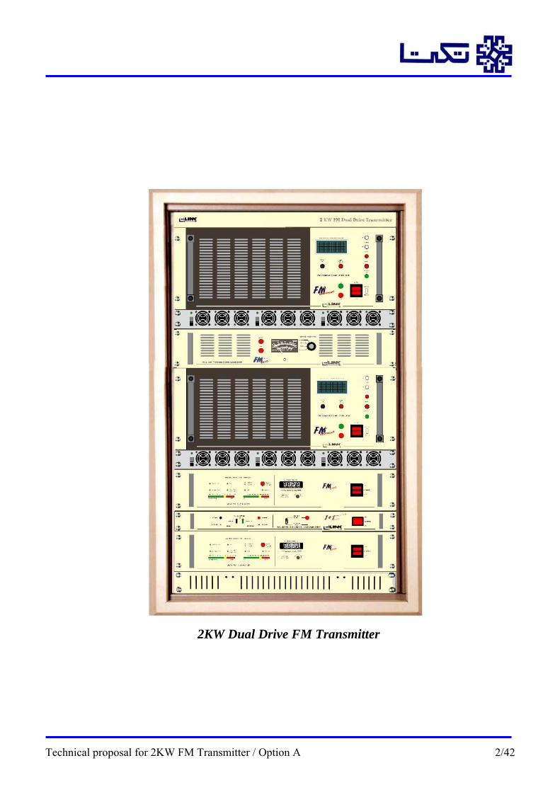
2KW Dual Drive FM Transmitter
Technical proposal for 2KW FM Transmitter / Option A 2/42

1- System General Description: 1.1: Transmitter system Composition:
The proposed 2KW dual drive FM transmitter advanced series is composed of following equipment.
Transmitter LOM:
Item Module Quantity 1 25W FM Exciter 2 2 Automatic changeover 1 3 1KW FM Amplifier 2 4 (2+1) Redundant power supply for 1KW FM amplifier 2 5 Combiner driver 1 6 19” Main rack 1
System composition
Transmitter Block diagram
Technical proposal for 2KW FM Transmitter / Option A 3/42

Transmitter Block Diagram
Technical proposal for 2KW FM Transmitter / Option A 4/42

2- FM Transmitter General Description: 2.1: FM EXCITER:
The "SERIES 2000" 25W FM EXCITER, meets the norms and requirements currently necessary for radio broadcasting, bearing in mind the high quality of the audio signal, which normally comes from a digital source, (compact disk, music or advertising stored on a hard disk, etc.).
Exciter front panel & Top
The "SERIES 2000" 25W FM EXCITER generates a high quality Frequency Modulated signal wihch surpasses the present rules governing FM material. The working frequency is generated in a "Direct Oscillator" without multiplying or converting it, and so the spectral integrity and the Sound/Noise ratio are notably improved.
The aforementioned Direct Oscillator (Direct V.F.O) has been constructed using the "SMD" technique and incorporates transistors with extraordinarily low noise, and " MMIC" monolithic amplifying devices. The Direct Oscillator "Direct V.F.O" is housed in a thick walled metal box to protect the signal wich is generated, from external electric and magnetic fields.
The working frequency is controlled via a "PLL" type regulating device, with parallel type decimal format programming. In this way the frequency is selected directly via 4 rotating selectors; the hundreds, tens, units and tenths, of the desired frequency. An external selection is possible when the EXCITER is used in type "N+1" etc., automatic systems.
The power amplification stage delivers 20W and it has a wide bandwidth so it does not require any adjustment. An Automatic Gain Control (A.G.C.) system allows the
Technical proposal for 2KW FM Transmitter / Option A 5/42
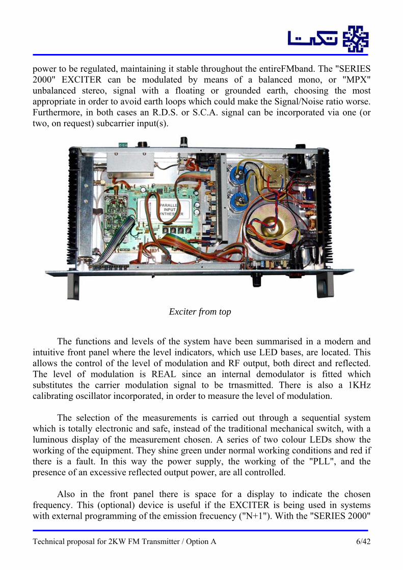
power to be regulated, maintaining it stable throughout the entireFMband. The "SERIES 2000" EXCITER can be modulated by means of a balanced mono, or "MPX" unbalanced stereo, signal with a floating or grounded earth, choosing the most appropriate in order to avoid earth loops which could make the Signal/Noise ratio worse. Furthermore, in both cases an R.D.S. or S.C.A. signal can be incorporated via one (or two, on request) subcarrier input(s).
Exciter from top
The functions and levels of the system have been summarised in a modern and
intuitive front panel where the level indicators, which use LED bases, are located. This allows the control of the level of modulation and RF output, both direct and reflected. The level of modulation is REAL since an internal demodulator is fitted which substitutes the carrier modulation signal to be trnasmitted. There is also a 1KHz calibrating oscillator incorporated, in order to measure the level of modulation.
The selection of the measurements is carried out through a sequential system which is totally electronic and safe, instead of the traditional mechanical switch, with a luminous display of the measurement chosen. A series of two colour LEDs show the working of the equipment. They shine green under normal working conditions and red if there is a fault. In this way the power supply, the working of the "PLL", and the presence of an excessive reflected output power, are all controlled.
Also in the front panel there is space for a display to indicate the chosen frequency. This (optional) device is useful if the EXCITER is being used in systems with external programming of the emission frecuency ("N+1"). With the "SERIES 2000"
Technical proposal for 2KW FM Transmitter / Option A 6/42
EXCITER you can externally change the output power, the working frequency (as has already been said), and also you can block or activate the RF output using an "Interlock" device. The initial adjustments for setting up the equipment are contained in a single readjustment of the modulation level according tot he level of the signal (whether it is mono or MPX) which is applied to the EXCITER.
The correct working of the EXCITER can be controlled from a logical (+12V) output which is activated from the moment of the (correct) switching on of the equipment. If there is an RF output fault, power supply failure or simply a block in the equipment, the output is deactivated. If there is a fault in the EXCITER the aforementioned logical signal can activate a reserve system or "N+1" etc.
THE EXCITER is presented in a "Rack" format two "U"s high, with the connection situated in the rear panel. The heat radiators which belong to the power stages of RF and the power supply are situated at the two sides of the equipment. In this way they can receive a convection current of air which is not interrupted by the different depths of other equipment as is the case when the said radiators are mounted in the rear panel.
The front panel has had a lamina of Polycarbonate ("Lexan") applied to it which protects it from external agents, scratches, etc. and which is easy to clean. The normal power supply is 220V c.a., but on request it can be supplied adapted to 110-115V c.a. supplies.
Technical proposal for 2KW FM Transmitter / Option A 7/42

Exciter Block diagram:
Technical proposal for 2KW FM Transmitter / Option A 8/42

2.2: Automatic Changeover Unit:
It is quite usual to have a reserve EXCITER available at radio broadcast installations, because this is one of the most essential pieces of equipment or guaranteeing transmission continuity. The current trend is to produce transmitters with redundancy technique in order to be able to guarantee high reliability of the installation amplification section, but not so with respect to excitation.
When the TRANSMITTER is low power, with the EXCITER included as an
integral part within this same TRANSMITTER, it is recommended that a complete unit is made available to provide transmission continuously by simple replacement.
The reserve EXCITER or TRANSMITTER will replace the main unit in those
cases in which a failure or fault involving the main EXCITER or TRANSMITTER interrupts the broadcast, It is also desirable that the switch-over from the main unit to the reserve is performed automatically, since most installation are unmanned, and also because they are often located at remote sites and/or are not very accessible. This usually means that the time between the failures occurring and an engineer arriving at the remote site to carry out the replacement operation is quite unacceptable. The availability of small, coaxial power relays makes it relatively easy to develop simple automatic systems that detect the failure and subsequent connection of the reserve unit in a rapid fashion.
The automatic exciter selector (or low power transmitters) (changeover) 1+1 from
LINK Comunicaciones include, in a single stylized "Rack for one unit (44.5 mm), t he entire electronics system, plus the necessary coaxial relay. The front panel intuitively displays all the required information for establishing the current operational status of the equipment with a simple glance.
Automatic Changeover Unit
The logic circuits for the automatic exciter-transmitter selector 1+1 includes the following functions:
a) Automatic changeover of the exciter-transmitter connected as (MAIN) to the
(RESERVE) when a failure occurs in the former. The (FAILURE) information may come from the actual EXCITER-TRANSMITTER (all LINK Comunicaciones. equipment provides this information), or directly from the RF signal that enters the
Technical proposal for 2KW FM Transmitter / Option A 9/42

coaxial relay (selectable by means of an internal Jumper). When the FAILURE signal comes from the actual equipment, it can usually be adjusted so that the logic signal is enabled as from a specific power reduction threshold (this depends on the actual equipment).
b) When performing the EXCITER-TRANSMITTER changeover operation, the AUTOMATIC SELECTOR 1+1 switches off the power supply to the faulty unit (MAIN), switches over the RF output using the coaxial relay, switches the MPX modulation unit over to RESERVE and then switches the power supply back on. During the time required to perform all these switching operations, which only takes a few milliseconds, an interlock device is used to isolate the EXCITER TRANSMITTER outputs in order to prevent the coaxial relay switching in a hot condition (with RF power present).
c) lf the automatic "RESET" mode has been selected, a five-minute timer operation commences after a changeover from MAIN to RESERVE operation and when this time period expires the system will respond by switching back to the MAIN unit and attempting to put it into normal service. If this is successful, the system will then continue in this way as if nothing had happened (a case of isolated incident). lf the operation is unsuccessful (permanent failure), the system will continue with the RESERVE equipment in operation permanently and the MAIN is recorded as faulty.
d) If manual RESET has been selected, this second opportunity does not take place until a manual reset is performed or a power supply cut initiates a new sequence.
e) A remote control and information system uses logic signals to provide permanent indication of the current operation status of the equipment, and also to activate the remote RESET. LINK Comunicaciones has suitable interface cards available for activating or transmitting logic signals by means of opto couplers or voltage free relay contacts.
F) In the case of a failure of the AUTOMATIC SELECTOR 1+1 electronic circuits, the MAIN EXCITER TRANSMITTER will remain switched on and fully operational.
Technical proposal for 2KW FM Transmitter / Option A 10/42

2.3: 1KW Amplifier: The 1 KW ADVANCED SERIES FM transmitter form part of a new series of
compact transmitters by LINK Communicaciones S.A. can be used as power amplifier modules in this proposed system. New technological advances make it possible to construct smaller and smaller electronic equipment, and at a lower cost, and without any reduction in quality.
1KW Power Amplifier
Technical proposal for 2KW FM Transmitter / Option A 11/42
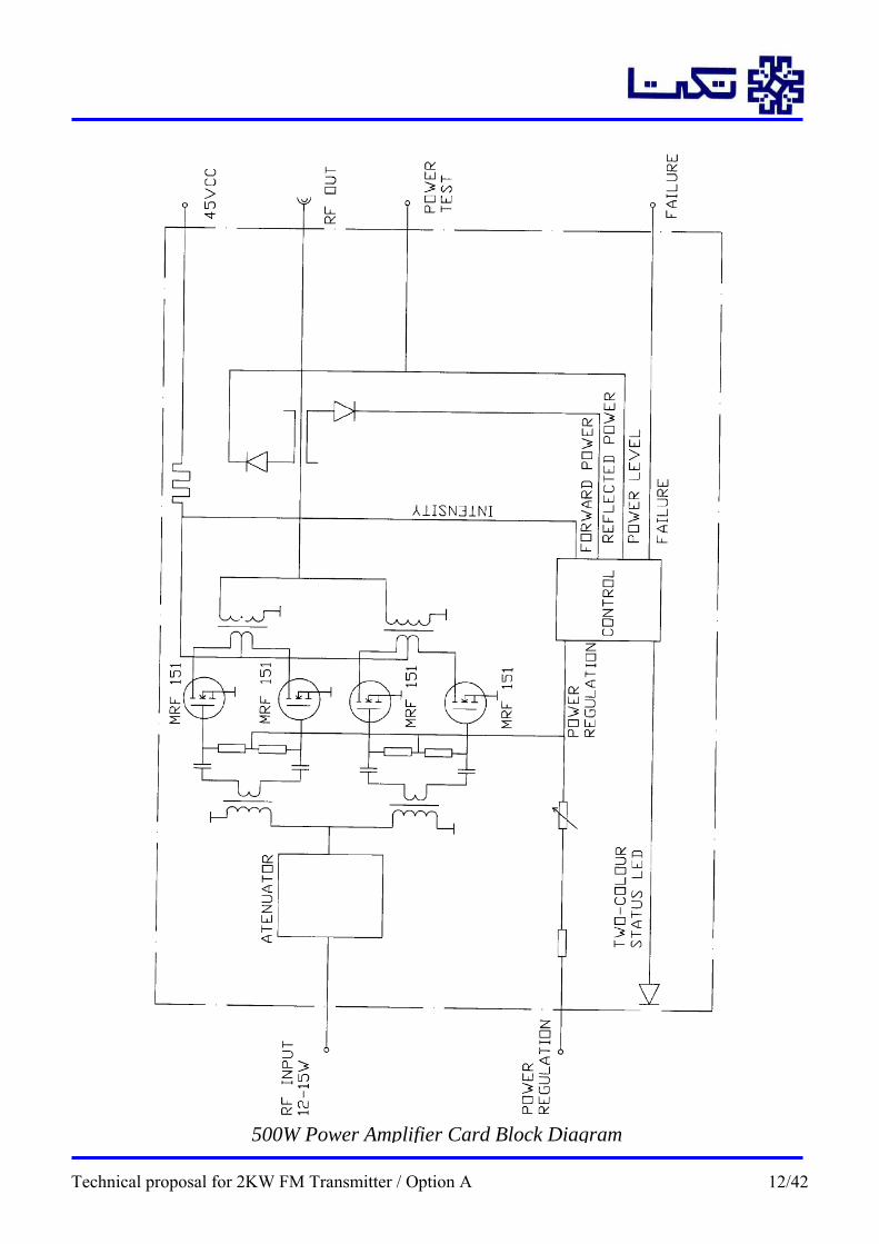
500W Power Amplifier Card Block Diagram
Technical proposal for 2KW FM Transmitter / Option A 12/42
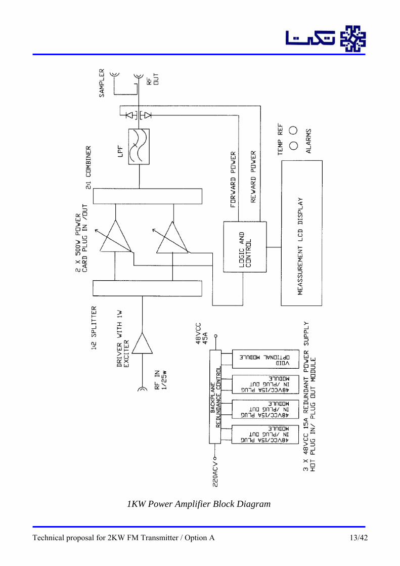
1KW Power Amplifier Block Diagram
Technical proposal for 2KW FM Transmitter / Option A 13/42
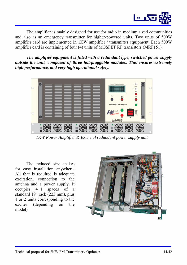
The amplifier is mainly designed for use for radio in medium sized communities and also as an emergency transmitter for higher-powered units. Two units of 500W amplifier card are implemented in 1KW amplifier / transmitter equipment. Each 500W amplifier card is containing of four (4) units of MOSFET RF transistors (MRF151).
The amplifier equipment is fitted with a redundant type, switched power supply
outside the unit, composed of three hot-pluggable modules. This ensures extremely high performance, and very high operational safety.
1KW Power Amplifier & External redundant power supply unit
The reduced size makes
for easy installation anywhere. All that is required is adequate excitation, connection to the antenna and a power supply. It occupies 4+1 spaces of a standard 19" rack (223 mm), plus 1 or 2 units corresponding to the exciter (depending on the model).
Technical proposal for 2KW FM Transmitter / Option A 14/42
The TRANSMITTER incorporates circuits for manual or remote start. It is fitted with a 220 V outlet for powering the exciter which comes on-line or goes off-line depending on whether the TRANSMITTER is on or off.
The various components are protected by including two soft-start systems: The
first makes a normal connection to the power supply network, but after a brief cut (micro-cut) the new connection is delayed for a few seconds to prevent the typical current peaks of connections to switched power supplies. This prevents possible tripping of magnetic-thermal switches or fusing in the event of micro-cuts in the electricity supply.
The second soft-start device prevents the sudden RF power peak when connecting
the "PLL" of the exciter and activating its output. This sudden connection causes dangerous current peaks in the power transistors. The power control voltage is kept at zero when there is no excitation. When excitation appears the control voltage slowly increases as does the power (over several seconds) until the desired output level is reached. Any cut in the excitation, however brief, restarts the process of a slow power increase.
Readouts of the different transmitter variables are shown on an alphanumeric LCD screen. A button allows sequential selection of the different displays that appear on the screen. The screen is normally unlit. Pressing any button lights the screen for 30-45 sec to simplify the readings. By default the first screen is activated when the unit is turned on. Readings outside the limits are indicated by a flashing display which remains lit to indicate an error condition. The screen also lights up whenever there is any operational error.
The display shows the values for POWER, REFLECTED POWER, VOLTAGE, CURRENT, and TIMER. It also indicates the DATA BUS DIRECTION number for the Tele-information system.
Technical proposal for 2KW FM Transmitter / Option A 15/42
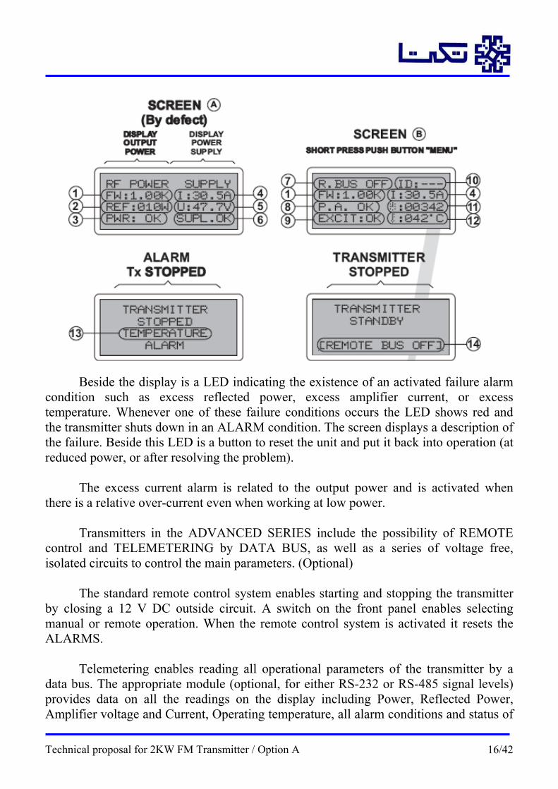
Beside the display is a LED indicating the existence of an activated failure alarm
condition such as excess reflected power, excess amplifier current, or excess temperature. Whenever one of these failure conditions occurs the LED shows red and the transmitter shuts down in an ALARM condition. The screen displays a description of the failure. Beside this LED is a button to reset the unit and put it back into operation (at reduced power, or after resolving the problem).
The excess current alarm is related to the output power and is activated when there is a relative over-current even when working at low power.
Transmitters in the ADVANCED SERIES include the possibility of REMOTE control and TELEMETERING by DATA BUS, as well as a series of voltage free, isolated circuits to control the main parameters. (Optional)
The standard remote control system enables starting and stopping the transmitter by closing a 12 V DC outside circuit. A switch on the front panel enables selecting manual or remote operation. When the remote control system is activated it resets the ALARMS.
Telemetering enables reading all operational parameters of the transmitter by a data bus. The appropriate module (optional, for either RS-232 or RS-485 signal levels) provides data on all the readings on the display including Power, Reflected Power, Amplifier voltage and Current, Operating temperature, all alarm conditions and status of
Technical proposal for 2KW FM Transmitter / Option A 16/42

the transmitter components. This BUS also enables turning the unit on or off, adjusting the operating power or resetting the alarms (Remote control by bus).
Incorporating a data concentration unit such as the TELEMETRY ROUTER from LINK Communicaciones S.A. enables concentrating the data received from other units the ADVANCED series and transmitting them by modem, cell phone etc. to a control center.
It is also possible to use a data transmission device such as the SUPERVISOR EQUIPMENT, from LINK Communicaciones S.A. to transmit messages in a simpler form such as SMS to a GSM cell phone, and be notified in the event of any failure condition or to consult any parameter using a cell phone. (This unit also enables remote start, etc. or any other functions of the transmitter center.)
TRANSMITTERS in the ADVANCED SERIES are normally excited at a power of about 20-25 W (normal exciters, adjusted to this power). It is possible to excite them with less than 1W(1W, SERIES 2000 Exciter from LINK Communicaciones S.A.) by installing a suitable preamplifier module in the transmitter (optional). The transmitter is already fitted with a suitable slot and connectors for this module. (Reference 022.401-2)
The switched power supply is extremely rugged and includes a system to limit the maximum current to protect the RF power transistors and the power supply itself. Stability of the power supply is guaranteed by efficiency within a voltage range of 150 to 250 V.
In addition, the output power is maintained extremely stable by an AGC system (Automatic Gain Control), which maintains the set power level even though there are changes in the working frequency, the power supply or the excitation.
The design of ADVANCED SERIES transmitters made a careful study of operational safety and included REDUNDANCY of the two most vulnerable parts, the RF power amplifiers and the power supply. At the same time maintenance work was simplified by the reduced dimensions (3-4 "U" high and 420mmin depth).
Fitting the RF amplifiers with a pluggable circuit board (compatible with other transmitters from LINK Communicaciones S.A.) makes any eventual cleaning or repair operations very simple, without any need to remove the unit from the rack and keeping it operation (at lower power) as the amplifiers are extracted from the front. Access to the control circuits and some parts of the power supply is also possible from the front panel, without any need to dismantle the unit. The section dedicated to WIRING DIAGRAMS and TECHNICAL SETTINGS includes drawings and instructions on how to access the different parts.
Technical proposal for 2KW FM Transmitter / Option A 17/42

2.3.1: Amplifier’s power supply: The power supply is designed under the same principle. It consists of 3 modules
in redundant configuration enabling the transmitter to operate at the same or slightly reduced power with one of them off-line. These modules are also removed from the front and this operation may be performed with the unit in operation.
The power supply unit can work with up to 4 modules simultaneously. The modules are connected to a “Blackplane”, including a control circuit of the modules. In the unit of 1Kw FM Transmitter Series Advanced, the power supply has 3 modules of 48V voltage output dc, and 15Amp per unit, each one connected to the Backplane.
The 1Kw FM power amplifier unit, drains 30 Amp approximately of DC, and each module is giving 10 Amp. (66% of the nominal intensity of each module).
If one module fails the Backplane control circuit, will order the 2 active modules to give 100% of power output, therefore the transmitter still receive 30 Amp. required for the correct function of the unit.
The modules of the power supply can be plug-in and plug-out, in hot. When the fail module is exchanged, the power supply control circuit will return to the initial status, giving each module again 10Amp DC. This power supply is used mainly for repeaters transmission centers of mobile phones, which are using thousands of units.
Amplifier’s Power supply (4 Sluts)
The rectifier modules provide unprecedented power density and power levels in a
true plug and play format. With a wide range of available voltages, power ratings, and form factors, the rectifiers provide optimal and cost effective solutions for your power needs.
We have used 3 sluts power supply for 1KW amplifier unit.
Technical proposal for 2KW FM Transmitter / Option A 18/42

Amplifier’s power supply (one slut), from top
The advantages: Optimization – The Power rectifiers are optimized for the demanding power
needs of wireless communications, enterprise and broadband access equipment. SMALL SIZE, BIG POWER – These compact 1RU rectifiers can provide up to
2500 Watts of power. The small size frees up space to reduce system size or incorporate additional electronics.
Industry Leading Efficiency – An industry leading 93% efficiency reduces the thermal load thus improving the overall reliability and availability of the system.
Flexibility – These rectifiers are designed to operate as an integral component in Valere’s Enterprise DC Power Systems. They are extremely flexible and can be operated either with a system controller or as a stand-alone module in enterprise applications.
Technical proposal for 2KW FM Transmitter / Option A 19/42

The features: • Small 1RU Footprint • Output Voltages from 12V to 48V • Output Power up to 2500W • Typical efficiency 93% • Wide Range Operating Temperature (from -40°C to +70°C) • Universal AC Input • Power-factor Correction • Hot-Pluggable • Redundant Parallel Operation • Active Load Sharing • NEBS Level 3 Certified • UL60950 Recognized • CSA C22.2 No. 60950-00 Certified • VDE EN60950 Certified • Advanced Internal Monitoring
AC Input Wire Sizing: This system utilizes an individual feed AC architecture (Figure 1) via a rear IEC 319.
Individual Feed AC Wiring Architecture
Each rectifier is fed by an individual AC breaker and cord as seen in the figure above. See Table 3 for breaker and wire sizing.
Technical proposal for 2KW FM Transmitter / Option A 20/42

DC Output Wire Sizing: There are two main considerations for sizing DC wire, ampacity and voltage drop.
Ampacity refers to a safe current carrying level as specified by non-profit organizations such as Underwriters Laboratories and the National Fire Prevention Association, which publishes the National Electric Code. Voltage drop is simply the amount of voltage loss in a length of wire due to ohmic resistance of the conductor. DC wire may be sized for either ampacity or voltage drop depending on branch load loop length and conductor heating. In general, ampacity considerations will drive wire selection for short loop lengths (less than 50 feet) and voltage drop will drive wire selection for long loop lengths (greater than 50 feet). The National Electric Code table 310.16 provides ampacity values for various sizes, bundles, and insulation temperature rated wire.
Each system is equipped with two double hole lug DC connection pads located on the rear of the shelf as shown in Figure 2. Select a wire size for each position according to plant current rating as shown in Table 4. If the shelf is to receive additional rectifiers at a later date, select wiring for the maximum future installation. This shelf is not designed for connection to a battery system without the use of an external distribution panel. The polarity of the system is universal; therefore the polarity of the output is determined by the system grounding. Ground the system on the return bus bar.
DC Wire Diagram
AC input Plug in the appropriate cord in to the AC connections on the back of the shelf. DC Output DC connections are accomplished via the two rear bulk output connection as shown in the photo below. Connections are made using double hole lugs with 5/8” spacing and ¼” hole size. Select wire and lug sizes according to section “DC Output Wire Sizing”.
Technical proposal for 2KW FM Transmitter / Option A 21/42
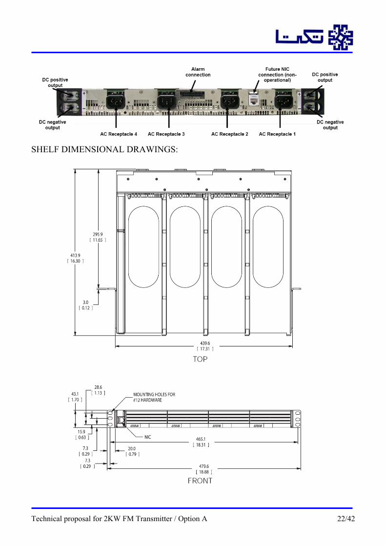
SHELF DIMENSIONAL DRAWINGS:
Technical proposal for 2KW FM Transmitter / Option A 22/42
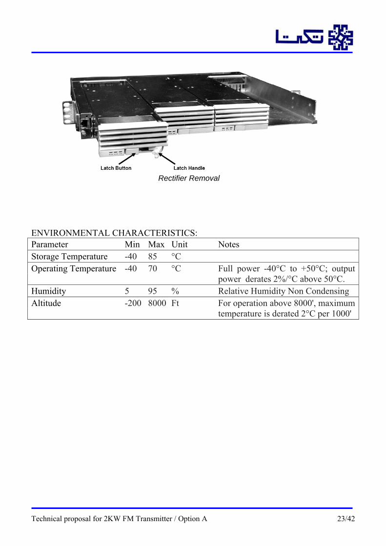
Rectifier Removal
ENVIRONMENTAL CHARACTERISTICS: Parameter Min Max Unit Notes Storage Temperature -40 85 °C Operating Temperature -40 70 °C Full power -40°C to +50°C; output power derates 2%/°C above 50°C. Humidity 5 95 % Relative Humidity Non Condensing Altitude -200 8000 Ft For operation above 8000', maximum temperature is derated 2°C per 1000'
Technical proposal for 2KW FM Transmitter / Option A 23/42
2.4: Combiner:
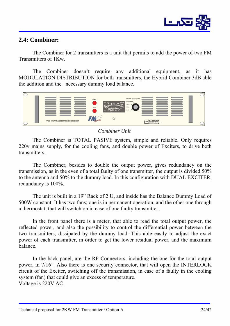
The Combiner for 2 transmitters is a unit that permits to add the power of two FM Transmitters of 1Kw.
The Combiner doesn’t require any additional equipment, as it has MODULATION DISTRIBUTION for both transmitters, the Hybrid Combiner 3dB able the addition and the necessary dummy load balance.
The Combiner is TOTAL PASIVE system, simple and reliable. Only requires 220v mains supply, for the cooling fans, and double power of Exciters, to drive both transmitters.
Combiner Unit
The Combiner, besides to double the output power, gives redundancy on the
transmission, as in the even of a total faulty of one transmitter, the output is divided 50% to the antenna and 50% to the dummy load. In this configuration with DUAL EXCITER, redundancy is 100%.
The unit is built in a 19” Rack of 2 U, and inside has the Balance Dummy Load of 500W constant. It has two fans; one is in permanent operation, and the other one through a thermostat, that will switch on in case of one faulty transmitter.
In the front panel there is a meter, that able to read the total output power, the reflected power, and also the possibility to control the differential power between the two transmitters, dissipated by the dummy load. This able easily to adjust the exact power of each transmitter, in order to get the lower residual power, and the maximum balance.
In the back panel, are the RF Connectors, including the one for the total output power, in 7/16”. Also there is one security connector, that will open the INTERLOCK circuit of the Exciter, switching off the transmission, in case of a faulty in the cooling system (fan) that could give an excess of temperature. Voltage is 220V AC.
Technical proposal for 2KW FM Transmitter / Option A 24/42
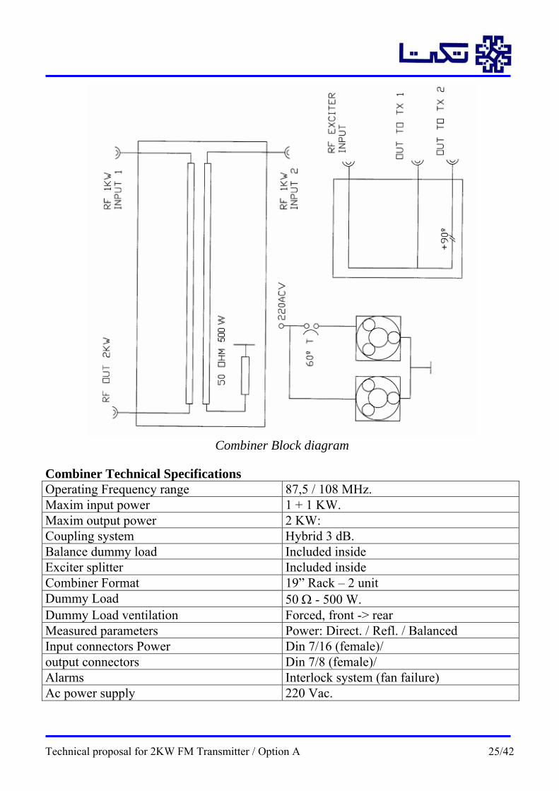
Combiner Technical Specifications Operating Frequency range 87,5 / 108 MHz. Maxim input power 1 + 1 KW. Maxim output power 2 KW: Coupling system Hybrid 3 dB. Balance dummy load Included inside Exciter splitter Included inside Combiner Format 19” Rack – 2 unit Dummy Load 50 Ω - 500 W. Dummy Load ventilation Forced, front -> rear Measured parameters Power: Direct. / Refl. / Balanced Input connectors Power Din 7/16 (female)/ output connectors Din 7/8 (female)/ Alarms Interlock system (fan failure) Ac power supply 220 Vac.
Combiner Block diagram
Technical proposal for 2KW FM Transmitter / Option A 25/42
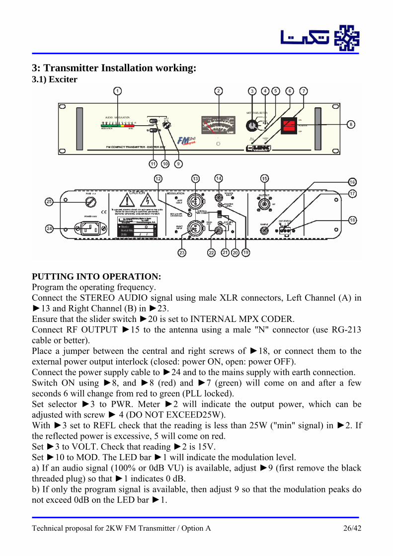
3: Transmitter Installation working: 3.1) Exciter
PUTTING INTO OPERATION: Program the operating frequency. Connect the STEREO AUDIO signal using male XLR connectors, Left Channel (A) in ►13 and Right Channel (B) in ►23. Ensure that the slider switch ►20 is set to INTERNAL MPX CODER. Connect RF OUTPUT ►15 to the antenna using a male "N" connector (use RG-213 cable or better). Place a jumper between the central and right screws of ►18, or connect them to the external power output interlock (closed: power ON, open: power OFF). Connect the power supply cable to ►24 and to the mains supply with earth connection. Switch ON using ►8, and ►8 (red) and ►7 (green) will come on and after a few seconds 6 will change from red to green (PLL locked). Set selector ►3 to PWR. Meter ►2 will indicate the output power, which can be adjusted with screw ► 4 (DO NOT EXCEED25W). With ►3 set to REFL check that the reading is less than 25W ("min" signal) in ►2. If the reflected power is excessive, 5 will come on red. Set ►3 to VOLT. Check that reading ►2 is 15V. Set ►10 to MOD. The LED bar ►1 will indicate the modulation level. a) If an audio signal (100% or 0dB VU) is available, adjust ►9 (first remove the black threaded plug) so that ►1 indicates 0 dB. b) If only the program signal is available, then adjust 9 so that the modulation peaks do not exceed 0dB on the LED bar ►1.
Technical proposal for 2KW FM Transmitter / Option A 26/42
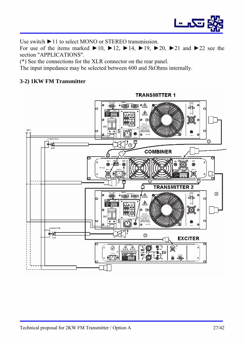
Use switch ►11 to select MONO or STEREO transmission. For use of the items marked ►10, ►12, ►14, ►19, ►20, ►21 and ►22 see the section "APPLICATIONS". (*) See the connections for the XLR connector on the rear panel. The input impedance may be selected between 600 and 5kOhms internally. 3-2) 1KW FM Transmitter
Technical proposal for 2KW FM Transmitter / Option A 27/42
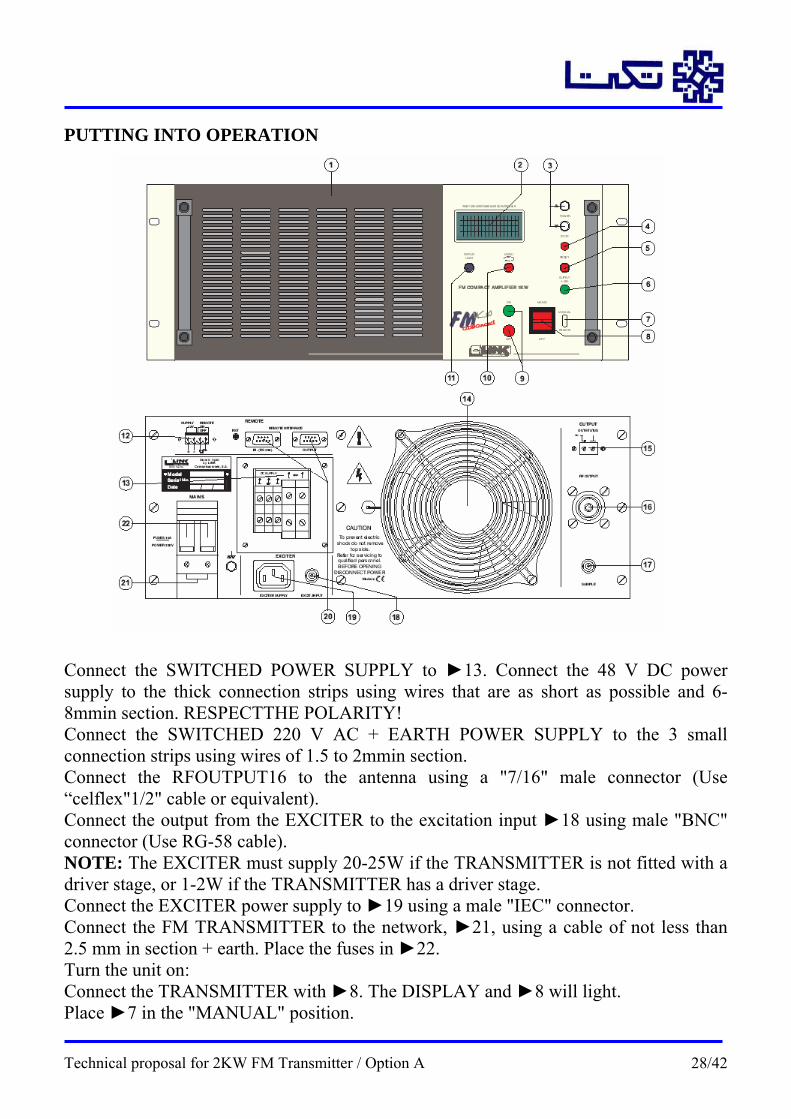
PUTTING INTO OPERATION Connect the SWITCHED POWER SUPPLY to ►13. Connect the 48 V DC power supply to the thick connection strips using wires that are as short as possible and 6-8mmin section. RESPECTTHE POLARITY! Connect the SWITCHED 220 V AC + EARTH POWER SUPPLY to the 3 small connection strips using wires of 1.5 to 2mmin section. Connect the RFOUTPUT16 to the antenna using a "7/16" male connector (Use “celflex"1/2" cable or equivalent). Connect the output from the EXCITER to the excitation input ►18 using male "BNC" connector (Use RG-58 cable). NOTE: The EXCITER must supply 20-25W if the TRANSMITTER is not fitted with a driver stage, or 1-2W if the TRANSMITTER has a driver stage. Connect the EXCITER power supply to ►19 using a male "IEC" connector. Connect the FM TRANSMITTER to the network, ►21, using a cable of not less than 2.5 mm in section + earth. Place the fuses in ►22. Turn the unit on: Connect the TRANSMITTER with ►8. The DISPLAY and ►8 will light. Place ►7 in the "MANUAL" position.
Technical proposal for 2KW FM Transmitter / Option A 28/42

Press button ►9 "ON", ►6 and ►9 will light up in green, the ventilator and the EXCITER will start. Check the DISPLAY for POWER, VOLTAGE, CURRENT: The VOLTAGE should be 48±1 V. The POWER should not exceed 1 kW. Otherwise the indication will flash. The REFLECTED POWER should not exceed 50W. Otherwise it will flash. The CURRENT should not exceed 35 A. Otherwise it will flash. Adjust the POWER by pressing ►10 for more than 2 sec and then pressing 3 to increase or reduce the power. In the event of excess REFLECTED POWER, CURRENT, or TEMPERATURE the TRANSMITTER will lock and ►4 will light up in red. UNLOCKTHE TRANSMITTER by pressing ►5. The use of components ►7, ►11, ►15, ►20 and ►12 is described in the "Application”.
Technical proposal for 2KW FM Transmitter / Option A 29/42

4: TECHNICAL SPECIFICATIONS 4-1) FM Exciter Technical specifications SPECIFICATIONS TARNSMISSION: WORKING FREQUENCY MHz 87,5 / 108 MHz STABILITY OF FREQUENCY ±5 x 10⁻⁶ CHANNEL SEPARATION (SYNTH.) 10 KHz, Steps ** (noise increase) GENERATION OF CARRIER Frequency Fundam. Oscillator DEVIATION AT 1KHz AND 0 dB. ±75 KHz TYPE OF MODULATION (AUDIO) 180 F3 TYPE OF MODULATION (MPX) 256 F3 MPX INPUT FOR 100% MOD. Assym./Imp.1K5/Sens./1.4/5.5 Vpp SUBCARRIER INPUT FOR 100% MOD. Assym./Imp.1K/Sens.-6/+10 dBm MPX RESPONSE 40-75000 Hz ± 0,2 dB. SUBCARRIER RESPONSE 20-100 KHz ± 1 dB FM NOISE REFERRED TO 100% TYP. <-75dB"C" curve (180 F3) and Desen DISTORT. AT 1KHz AND 100% MOD. 0,03% with de-emphasize 50µs (typ.) MONO OPTION: AUDIO INPUT FOR 100% MOD "Symm./Z: 600/5000 ohms; 0/+15 dBm DISTORT. AT 1KHz AND 100% MOD. 0.040% with De-emphasize 50µs(typ.) FM NOISE REFERRED TO 100% TYP. <-75dB"C" curve and De-emphasize AUDIO RESPONSE 30-15000 Hz ± 0.5 dB Pre-emp./ De-emph. STEREO OPTION: AUDIO INPUT L/R, 100% MOD "Symm./Z: 600/5000 ohms; 0/+15 dBm CROSSTALK L-R < 45 dB. DIST. L/R AT 1KHz AND 100% MOD. <0.08% S/N RATIO L/R <-70dB "C" curve and de-emphasize AUDIO L/R RESPONSE 30-15000Hz ± 0.5dB Pre-emp./ De-emph. PILOT FREQUENCY 19000Hz ± 1Hz PILOT LEVEL 9-10% PILOT OUTPUT (R.D.S. SYNCRO.) 0dBm RADIOFREQUENCY: NOMINAL OUTPUT POWER 25W.(Adjustable from 20->100%) HARMONICS LEVELS <-70dB SPURIOUS LEVEL < - 70 dB. MISCELLANEOUS: ALARMS (EXCESS OF:) S.W.R., COOL SYSTEM (25W) Convection POWER SUPPLY VOLTAGE 220 Vc.a.(110 Vc.a. on request) WORKING MARGIN 205 - 235 V (typical 195 – 260 V.) POWER DRAIN (25W) 70 W 19” Rack normalized
19" RACK 2U (88mm) and 215 depth
Technical proposal for 2KW FM Transmitter / Option A 30/42

4-2) 1KW FM Stereo Transmitter Technical specifications SPECIFICATIONS TARNSMISSION: Operating FREQUENCY MHz 87,5 / 108 MHz ADJ. REQUIRED ON CHANGING FREQ. No, wide band circuits RATED POWER 2000 W. (1000+1000 W.) ADJUSTMENT MARGIN 200 W. To 2000 W. NON-ESSENTIAL SIGNAL LEVELS <-65dB OUTPUT IMPEDANCE 50ohms. POWER STABILITY, V ±20% <-0.05dB OUTPUT CONNECTOR "7/16" Female EXCITATION (WITH DRIVER STAGE) >0.5W (request) EXCITATION CONNECTOR "BNC" Female TRANSMISSION SPECIFICATIONS Those of the EXCITER POWER SUPPLY: POWER SUPPLY Switched mode converter OPERATING SECURITY 2xRedundant, 3 modules Dc POWER SUPPLY 48V ±1V Dc RATED CURRENT 2X33A Ac POWER SUPPLY 220V VOLTAGE MARGIN WITHOUT VARIATION 150 – 250 VAC. AC RATED CURRENT 2 x 8A (at 220V) AVERAGE CONSUMPTION (WITHOUT EX.) 2 x 1700W VARIOUS: SWITCH ON/OFF OPERATION Manual or remote OPERATING INDICATIONS By alphanumeric L.C.D DISPLAY (X2) MEASURED PARAMETERS Dir./ Refl. PWR,v,a, and T؛C (X2) DISPLAYED INFORMATION SITUATION Final amp., exc, operating hours, remote control
on off adverssable bus, alarms (X2) ALARMS. Excess: reflected, current, temp (X2) COMUNICATION RS-485 or RS-232 REMOTE MEASUREMENTS BY BUS All display indication REMOTE CONTROL CAPACITY BY BUS On/off, power: Up/Down ISOLD. CIRC. REMOTE CONTROL On/off ISOLD. CIRC. INFORMATION Manual / remote, power drop, TX activated, mains
present MECHANICAL: POWER STAGE FORMAT 2 X 19” Rack 4 U. (178 mm) 420 mm. depth VENTILATION Forced direction front to rear WEIGHT WITH PACKAGING 2 x 18 Kg. POWER SUPPLY FORMAT 2 X 19” Rack 1 U. (45 mm) WEIGHT WITHOUT PACKAGING 2 X 11 Kg.
Technical proposal for 2KW FM Transmitter / Option A 31/42

5- DRAWINGS
Technical proposal for 2KW FM Transmitter / Option A 32/42

EXCITER Initial Diagram
Technical proposal for 2KW FM Transmitter / Option A 33/42

EXCITER Circuit Diagram
Technical proposal for 2KW FM Transmitter / Option A 34/42

Changeover Circuit Diagram
Technical proposal for 2KW FM Transmitter / Option A 35/42

Changeover Internal Layout
Technical proposal for 2KW FM Transmitter / Option A 36/42
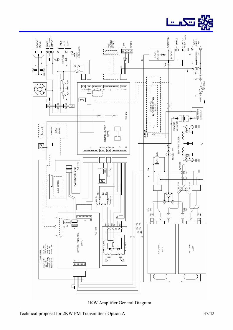
1KW Amplifier General Diagram
Technical proposal for 2KW FM Transmitter / Option A 37/42

500W Amplifier Card Circuit Diagram
Technical proposal for 2KW FM Transmitter / Option A 38/42

Combiner General Diagram
Technical proposal for 2KW FM Transmitter / Option A 39/42

Combiner Internal Layout
Technical proposal for 2KW FM Transmitter / Option A 40/42
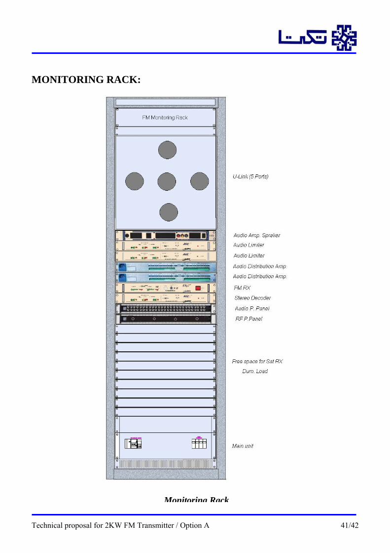
MONITORING RACK:
Monitoring Rack
Technical proposal for 2KW FM Transmitter / Option A 41/42

Monitoring Rack for 2KW FM TX – LOM:
Item DESCRIPTION Quantity1 40U 19" Rack 60 x 60 cm 1 2 2U Electric panel, with wiring and switches 1 3 FM professional Receiver 1 4 Professional Audio Stereo Decoder (demodulator) 1 5 Audio Distribution Amplifier, (two stereo inputs and six outputs) 2 6 Audio Patch panel 1 7 Audio Limiter (Limiter compressor) 2 8 Test Patch Panel R.F. With N connectors 10 In/out 1 9 Audio Amplifier , w/ Speakers 1
10 U-Link 5 ports 1 11 Dummy Load Resistance (for 2Kw) 1 12 RF patch panel 1
Technical proposal for 2KW FM Transmitter / Option A 42/42