technical optical control techniques for off-grid lighting
TRANSCRIPT

Date:
Introduction
The optical design of an off grid lighting product is important to both the lighting efficiency and the light distribution of the product. Proper design can efficiently shape the visible light emitted by the LED or LED array, putting light where it best serves the user and also controlling uncomfortable glare that can be a problem with bright point source LEDs. This Tech Note will introduce basic concepts in optical design, describe common materials used for optical components, and explore ways to increase the efficiency and the aesthetic appearance of the light delivery system of the product.
Optical Properties
Light interacts with different materials in different ways. Light can be reflected from a surface, as with a mirror or a white piece of paper. Light can be transmitted as with a clear piece of plastic or a translucent diffuser. Finally, light can be absorbed by a material as with a black piece of plastic. The type of interaction that occurs is a function of material type, thickness, and surface quality. Most materials exhibit multiple interactions where different fractions of incident light are reflected, transmitted, and absorbed.
Reflection: Light reflects from a surface in two primary ways. A specular reflection (Figure 1) occurs when the angle of incidence equals the angle of reflection (mirrored surfaces reflect this way). A diffuse reflection (Figure 2) occurs when the incident light scatters from the surface in many different directions (as from a white piece of paper).
© Lighting Global - May 2012
TechnicalNotesIssue 6 July 2011
Optical Control Techniques for Off-grid Lighting ProductsThis Technical Note introduces basic concepts in optical design for low power off-grid lighting products and suggests ways to improve optical efficiency. It is intended for manufacturers, distributors, and retailers. The Information contained in this article builds on previous Technical Notes. See also:http://www.lightingafrica.org/resources/briefing-notes.html
A ‘perfectly diffuse’ surface is called a Lambertian surface, where the light intensity leaving the material is directly proportional to the cosine of the angle θ between the observer’s line of sight and the surfacenormal (θr in Figure 1). The perceived brightness of a Lambertian surface will appear to be uniform when viewed from any direction.
Many materials exhibit both types of reflection at once, with some of the incident light scattering (diffuse reflection) and some of the light reflecting equal to the incident angle (specular) (Figure 3).
Figure 1.Specular Reflection:Angle of incidence θi =
Angle of reflection θr(Law of Reflection)
Figure 2.Diffuse Reflection:Incoming light is reflected in many directions.
Figure 3.Reflection with both diffuse and specular components

Optical Control Techniques for Off-grid Lighting ProductsIssue 6 July 2011
Transmission. Clear and translucent materials transmit light. Optically clear (transparent) materials (Figure 4) are used as lenses or cover plates and may or may not alter the light distribution from the LED source(s). Translucent materials (Figure 5) scatter or diffuse light that passes through them and can soften the very bright point source characteristic of an LED. A transparent sheet allows light to pass through so that objects behind the sheet can be viewed, while a diffuser will allow light to pass through but will scatter the light so that the object is obscured.
Absorption. Both reflective and transmissive materials will absorb some amount of light. This light is considered lost and will not contribute to the output of the luminaire.
Transparent materials will also reflect a fraction of the incident light at the material boundary. This is a function of the angle of incidence of the light with the transparent material surface: higher angles result in more reflection (Figure 6). At some incident angle θi, called the critical angle, all of the light will be reflected and none will be transmitted. This is called Total Internal Reflection (TIR). TIR is very efficient and is used extensively in the optical design of secondary lenses (see “Primary and Secondary Optics” below).
Light Distribution Basics
The light leaving a lighting product will have a specific distribution depending on the position of the light source and any optical components used to alter or shape the light beam. Many different light distributions are possible. There are two categories of distributions that are important for off grid lighting products.
Ambient lights are products with wide-angle distributions, where the light is often emitted in a 180° or 360° pattern around the fixture. Ambient lights are intended to light a room or other large space, and put light on the walls, floors, and sometimes the ceiling.
Task light products have controlled light patterns intended to direct light onto a smaller area create higher brightness. Often used for reading or detailed work, task lights should allow for the light beam to be positioned or aimed at a specific area (such as a piece of paper or a book – this is called the ‘task plane’). Task lights do not light walls or ceilings, although reflected light from the task plane will allow for some ambient light in the room.
Light distributions can be represented graphically with polar or rectilinear plots (Figure 7). These plots give the relative distribution of a light source over an angle of 90, 180, or 360 degrees.
© Lighting Global - May 2012
Figure 4.Light passing through anun-textured transparent material will leave an image of the source intact.
Figure 5.A diffuse or textured transparent material will scatter or redirect light and obscure an image.
Figure 6.Some fraction of incident light on a transmissive material will be reflected back toward the source

Optical Cavities
Many lighting products that use LEDs or CFLs have 3 common elements: the light source (LED or LED array, CFL), a transparent or translucent protective cover, and reflectors or reflective baffles. These elements form one or more optical cavities that reflect and direct the emitted light out of the fixture. The design of the optical cavity is crucial to both the appearance of the product, the light distribution, and the product fixture efficiency.
Optical designs should avoid elements within the optical cavity that trap light where it cannot escape (Figure 9). Optical components (reflectors, diffusers, and cover plates) should be located away from the light source to avoid near field absorption effects, and components should have high reflectance and transmissive properties (Figure 10).
Figure 10. A more efficient optical cavity
Optical Control Techniques for Off-grid Lighting ProductsIssue 6 July 2011
© Lighting Global - May 2012
Figure 7. LED distribution with a polar and a linear plot
Manufacturers of lighting products will sometimes list the FWHM (full width half max) angle of the light distribution. This is the angle where the illuminance is ½ the peak (maximum) value. Small FWHM angles are usually (but not always) an indication of a tightly focused (narrow beam) distribution. The FWHM angle of Figure 7 ≈ 58° x 2 ≈ 116°.
Illuminance plots (Figure 8) are used to describe the illuminance levels from a light source over a specified task plane. This is usually done for a task light style product. The distance between the light source and the task plane is listed, and the area of the task plane is defined in m2. To meet the Performance Targets for the Lighting Africa program, for example, a lighting product must be capable of illuminating a 0.1 m2
surface at ≥ 25 lux.
Figure 8 Illuminance plot
Figure 9.A constrained optical cavity. Light leaving the LED can get self-absorbed or trapped in small corners.
FWHM is angle formed where intensity = 50%
Optical Control Techniques for Off-grid Lighting ProductsIssue 6 July 2011
© Lighting Global - May 2012
Primary and Secondary Optics
Some LED components incorporate a primary optic into the LED package that shapes the light distribution from the LED chip. Other packages do not, and light from the LED chip/phosphor is emitted directly from the LED (light from an LED chip has an essentially Lambertian distribution). Surface mount LEDs commonly have wide distributions, while through-hole LEDs have a range of distributions (wide to narrow) depending on the shape of the epoxy dome.
Any external reflector or lens can be considered a secondary optic, although the term usually refers to a lens or reflector cavity that fits over the LED itself (Figure 11). High performance secondary optics are designed for specific LED types and they should only be used for their intended LED package. Secondary optics are available to shape the LED output to virtually any distribution. As a rule, increasing the size of an optic tends to increase the optical coupling efficiency with the LED source. Secondary optics that spread the incoming light from the source are called diverging optics, and those that gather the incoming light into a collimated beam are called collimating optics. Good secondary optics can be >85% efficient, though some with very pronounced effects on the distribution (such as optics with rectangular or oval patterns) will be less efficient because of the high degree of optical transformation.
Lenses can be used for almost any optical distribution. Advantages include high efficiency, small size, durability, and the ability (with proper design) to use them as a window without additional external covers that lower the efficiency. They are, however, fairly susceptible to misalignment, which can lead to lower performance and dark/bright spots in the output. Lens surfaces can be smooth or textured (e.g. ripple lenses) and are available in a wide variety of distributions.
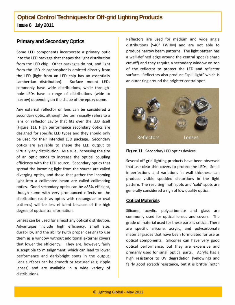
Reflectors are used for medium and wide angle distributions (>40° FWHM) and are not able to produce narrow beam patterns. The light pattern has a well-defined edge around the central spot (a sharp cut-off) and they require a secondary window on top of the reflector to protect the LED and reflector surface. Reflectors also produce “spill light” which is an outer ring around the brighter central spot.
Figure 11. Secondary LED optics devices
Several off grid lighting products have been observed that use clear thin covers to protect the LEDs. Small imperfections and variations in wall thickness can produce visible speckled distortions in the light pattern. The resulting ‘hot’ spots and ‘cold’ spots are generally considered a sign of low quality optics.
Optical Materials
Silicone, acrylic, polycarbonate and glass are commonly used for optical lenses and covers. The grade of material used for these parts is critical. There are specific silicone, acrylic, and polycarbonate material grades that have been formulated for use as optical components. Silicones can have very good optical performance, but they are expensive and primarily used for small optical parts. Acrylic has a high resistance to UV degradation (yellowing) and fairly good scratch resistance, but it is brittle (notch
Reflectors Lenses

Optical Control Techniques for Off-grid Lighting ProductsIssue 6 July 2011
© Lighting Global - May 2012
sensitive) and may not be appropriate for designs exposed to impact. Polycarbonate is very impact resistant, but without protective coatings it scratches easily and requires special additives to prevent yellowing from UV exposure. Glass is a good optical material that is very scratch resistant, but it is heavy and not impact resistant (tempered glass is an exception). Designs that use glass components should be avoided OR carefully evaluated to determine if they can pass the drop test in the Lighting Africa Quality Test Method (LA-QTM).
Other transparent plastics are also available such as polystyrene and polyethylene terephthalate (PET, PETG). These materials can be used for low cost optical covers and diffusers. The optical properties of these materials are inferior to acrylics and polycarbonates. Care should be taken if they are used for optical parts, and prototypes should always be evaluated prior to mass production.
Opaque white plastics, metalized plastics, painted metals and polished aluminum are all used for reflector parts. Off grid lighting products will more frequently use plastic parts because of cost and weight issues. With metalized plastics, a thin film of metal is deposited onto a plastic substrate. This metal layer must then be protected with a clear overcoat to prevent oxidation and damage to the relatively fragile metallic film.
Optical Component Aging
Some optical materials deteriorate with age. Plastic parts are subject to changes in their optical properties from exposure to heat, humidity, and UV (ultraviolet) radiation. Products exposed to daylight at any time will be exposed to UV radiation from the sun.
UV degradation of certain polymers occurs from exposure to UV and blue radiation. Damage from these high energy wavelengths causes the material to absorb more light in the UV and blue regions of the spectrum.
The result is a lower overall transmission and a noticeable yellow tint in the material. This type of degradation can also occur in opaque reflective plastics. White LEDs, CFL’s, and sunlight can cause this degradation and lower the optical efficiency of a product over time.
Dirt accumulation on an off grid light source is likely and can pose a problem if the dirt is able to accumulate on inner, inaccessible elements of the optics that cannot be cleaned by the user. Water entry or dust accumulation on inaccessible parts should therefore be prevented by proper ingress design.
Plastics are susceptible to scratching and chemical damage from cleansers and frequent cleaning. This will tend to lower the efficiency and light output of the product over time and, depending on the type of optic, may also change the light distribution.
Optical Design and Thermal Performance
All LEDs generate heat that must be conducted away from the LED to maintain performance and avoid damage while in use. Optical systems that trap the LED under layers of reflectors, lenses, diffusers, orsurrounding enclosures can increase the operating temperature of the LEDs themselves. This may lower the performance of the LEDs, and can also have aging effects on plastics that are in close contact and are heated by the LEDs. Thermal testing of LED products should always occur after complete final assembly, and optical component temperatures should be measured in addition to LED temperatures.
Ray Tracing and Computer-Aided Design (CAD)
Many LED manufacturers have computer files that describe their LED output. These can be loaded into ray tracing programs and used to simulate the light output of the final product. CAD design can be veryhelpful during the design process but should always be verified with real world prototyping.

Optical Control Techniques for Off-grid Lighting ProductsSub Heading (Calibri 13 Font)
© Lighting Global - May 2012
Intensity and Glare
LEDs are considered bright point source emitters. The luminous flux from an LED is emitted by a relatively small surface area (LED chip size < 1 mm2). This high surface brightness can be a problem with LED products and can cause discomfort and glare issues (Figure 12).
Contrast this with a CFL lamp, where the glass lamp tube emits light from a much larger surface area. This type of emission is less likely to cause discomfort because the light energy that reaches a viewer’s eye is emitted by a large surface area and will consequently appear ‘softer’. One technique to minimize bright hotspots and discomfort issues from a lighting product is to increase the emissive surface of the light source. This can be achieved with lenses, diffusers, and/or reflectors that spread the light output from a bright point source to a softer, larger emission surface (Figure 13).
Figure 12. A transparent optic will allow direct viewing of the bright LED source and may cause discomfort.
Figure 13. A diffuser or patterned lens optic scatters light and increases the apparent emissive surface, leading to a softer light appearance.
Glare can also be controlled by shielding the light source from direct view with reflectors or hoods built into the housing. A “cutoff angle” is formed that helps keep the light source out of direct view (Figure 14). A narrow cutoff angle (< 45°) is common for task lights, while a larger cut-off, or no cut-off angle, is more frequently used for ambient lights.
Figure 14. A cut-off angle may be used to shield the light source from view, thereby preventing eye discomfort caused by glare.
Light Safety
High light intensities from LEDs can be a safety concern. The primary danger comes from the blue portion of the spectrum (400-500 nm) and exists in situations that exhibit high surface intensities (surface intensity = intensity per unit emissive area). High power LEDs can be dangerous to view directly, and care should be given to reduce harsh specular reflections from secondary optics. Diffusers can significantly reduce surface intensity and should be considered to increase user comfort and safety when high powers LEDs (> 1 watt) are used.
Standards are available to define safety limits for LED products. Manufacturers should refer to IEC/TR 62471-2:2009 “Photobiological safety of lamps and lamp systems - Part 2: Guidance on manufacturing requirements relating to non-laser optical radiation safety” for more information.