technical note - nasa · weights of lox and lh2 were, respectively, 84,244 and 16,954 pounds for a...
TRANSCRIPT

N A S A TECHNICAL NOTE
b
INVESTIGATION OF S-IV ALL SYSTEMS VEHICLE EXPLOSION
Compiled and edited by J. B. Gayle George C. Marshall Space Flight Center Hz.mtsuille, Ala.
NATIONAL AERONAUTICS AND SPACE ADMINISTRATION 0 WASHINGTON, D. C. 0 SEPTEMBER 1964
https://ntrs.nasa.gov/search.jsp?R=19640020175 2020-05-26T00:38:49+00:00Z
TECH LIBRARY KAFB. NM
INVESTIGATION O F
S-IV ALL SYSTEMS VEHICLE EXPLOSION
Compiled and edited by J. B. Gayle
George C. Marshal l Space Fl ight Center Huntsville , Ala.
NATIONAL AERONAUTICS AND SPACE ADMINISTRATION

TABLE OF CONTENTS
Page
SUMMARY ................................................... 1
INTRODUCTION .............................................. 1
THE COMMITTEE ............................................. 2
MODE OF INVESTIGATION ..................................... 2
FINDINGS .................................................. 3
Basement Level ........................................ 4 Level No . 1 ........................................... 5 Level No . 2 (F i r ing Level) ............................ 5 Level No . 3 ........................................... 5 Level No . 4 ........................................... 5 Level No . 5 ........................................... 6 Level No . 6 ........................................... 6 Level No . 7 and Above ................................. 7
SIGNIFICANCE OF FINDINGS WITH RESPECT TO MAGNITUDE OF EXPLOSION .............................................. 7
Estimate of Explosive Weight Based on Damage t o TS-1 But le r Bui ld ing ................................... 7
Estimate of Explosive Weight Based on Damage t o Cover P r o t e c t i v e Assembly ......................... 8
Estimate of Explosive Weight Based on Damage t o I-Beams ........................................... 8
Estimate of Explosive Weight Based on Glass Damage ............................................ 9
Estimate of Explosive Weight Based on Fragment Dispersion ........................................ 10
Summary of Explosive Weight Estimates ................ 1 2
SIGNIFICANCE OF FINDINGS WITH RESPECT TO SIZE AND DURATION OF FIREBALL ...................................... 13
SIGNIFICANCE OF EXPLOSION WITH RESPECT TO PROBABILITY OF FUTURE INCIDENTS ...................................... 14
BLAST GAUGES ............................................. 15
CONCLUSIONS .............................................. 15
REFERENCES ............................................... 48
iii
I

Table
I
111
N
V
LIST OF TABLES
Ti t ie ’ . Page
Propellants and Gases on Board A l l Systems Vehicle a t Time of Explosion ...... 16
Ident i f icat ion of Fragments Shown on Figure 3. ................................. 17
Data for Selected Fragments. .............. 24
Calculation of In i t ia l Veloc i t ies for Selected Fragments ........................ 30
Summary of LOX/LH2 Experience with Full- Scale Flight Weight Tankage ............... 31
i v

LIST OF FIGURES
Figure
1
2
3
4
5
6
7
8
9
10
11
1 2
13
14
15
16
Movement of Vehicle After Explosion ................. V i e w of Test Stand After Explosion .................. Fragment Dispersion Pat tern ......................... Glass Breakage Pattern .............................. Damage to But le r Bui ld ing . TS-1 ..................... Liquid Hydrogen and Oxygen Sleds (3rd Level) ........ Vehicle Debris on Top of Engines (4th Level) ........ Bent S t ruc tura l Members (5th Level) ................. Cable Raceway and Elevator Shed (6th & 7th Level) ... Cover P r o t e c t i v e Assembly ........................... Damaged I-Beam ....................................... Rela t ion Between I n i t i a l V e l o c i t y and Ground Range (Low Velocity’ Range) .......................... Rela t ion Between I n i t i a l V e l o c i t y and Ground Range (High Veloc i ty Range) ......................... Sequence of Explosion ............................... Fireball Diameters for Various Weights and Types of P rope l l an t s ...................................... Fireball Duration for Various Weights and Types of Propel lan ts .....................................
Page
32
33
34
35
36
37
38
39
40
41
42
43
44
45
46
4 7
V

TECHNICAL NOTE D-
INVESTIGATION OF S-IV ALL SYSTEMS VEHICLE EXPLOSION
SUMMARY
I n v e s t i g a t i o n o f t h e S-IV A l l Systems Vehicle explosion indicated the fol lowing: high explosive equivalent , 1 p e r c e n t ; f i r e b a l l d i a m e t e r , 380 f e e t ; f i r e b a l l d u r a t i o n , 11 seconds; maximum fragment radius , 1500 f e e t . The r e l a t i v e l y low y i e l d w a s due t o s u b s t a n t i a l l y i n s t a n t a n e o u s i g n i t i o n o f t h e s p i l l e d p r o p e l l a n t s which probably resu l ted from the extreme flammability of hydrogen. I f t h i s t r e n d p e r s i s t s i n t h e s c a l e model t es t programs now i n p r o g r e s s , some r e d u c t i o n i n t h e 60 percent h igh exp los ive equ iva len t cu r ren t ly u sed fo r s i t i ng o f LOX/LH2 veh ic l e s may be poss ib l e .
INTRODUCTION
On January 24, 1964, t h e S-IV A l l Systems Vehicle exploded and burned during the terminal s tages of the countdown f o r i t s i n i t i a l t e s t f i r i n g . The incident which occurred a t Test Stand 1 of the Douglas Aircraf t Company (DAC), Sacramento t e s t f a c i l i t y was t h e second known f a i l u r e i n v o l v i n g s i g n i f i c a n t q u a n t i t i e s o f t h e p r o p e l l a n t Combination, LOX/LH2. Inasmuch as the p rev ious fa i lure involv ing these p rope l l an t s occu r red du r ing t he boos t e r phase o f t he f i r s t Cen tau r launch, the S-IV A l l Systems Vehicle explosion w a s t h e f i r s t f o r which a de ta i l ed examina t ion o f t he r e su l t i ng damage w a s poss ib l e .
A number of small scale s t u d i e s c u r r e n t l y are being conducted to assess the hazards assoc ia ted wi th the use o f LOX/LH2 and other pro- pel lant combinat ions; however , extrapolat ion of the resul ts of these s t u d i e s t o o b t a i n s i t i n g c r i te r ia in t roduces a considerable degree of unce r t a in ty which can best be e l iminated or minimized by tes ts in- vo lv ing fu l l - sca le t ankage of f l igh t weight cons t ruc t ion . Al though such tests are contemplated, they are not expected to be accomplished be fo re FY-66. Therefore , i t w a s considered mandatory that a compre- hens ive i nves t iga t ion be made of the S-IV A l l Systems Vehicle explosion and tha t t he i n fo rma t ion b.e ana lyzed w i th r e spec t t o t he cu r ren t ly a c c e p t e d s i t i n g c r i t e r i a f o r LOX/LH2.
THE. COMMITTEE-
The chairman of the investigating committee was D r . W . R. Lucas, Chief of the Materials Division, Propulsion and Vehicle Engineering Laboratory, Marshall Space Flight Center (MSFC). The a l t e r n a t e c h a i r - man was D r . J. B. Gayle, Chief of the Physical Chemistry Section, Chemistry Branch, Mater ia ls Divis ion, MSFC. Other members from MSFC were: Mr. H. C. Dyer, Test Laboratory; Mr. L. L . Roberts , Safety Office; and Mr. 0. S . Tyson, MSFC res iden t eng inee r a t DAC Sacramento. Members f rom other NASA organizat ions were: D r . F. E . Be l l e s , Lewis Research Center; Mr. P. V. King, Cape Kennedy; and Mr. G. D. McCauley, NASA Headquarters. Members from A i r F o r c e i n s t a l l a t i o n s were: Mr. . C . R. Cooke, Edwards A i r Force Base, and Mr. L. J. U l l i a n , P a t r i c k A i r Force Base. D r . P . A . Longwel l , Ca l i fo rn ia In s t i t u t e of Technology, s e rved a s a member r ep resen t ing DAC. Consul tants to the commit tee were Mr. A . J . Hoffman, Ba l l i s t i c Resea rch Labora to r i e s (BRL), and Mr. W. M. Smalley, Aerospace Corporation.
MODE OF INVESTIGATION
The committee met a t 9:00 a.,m. a t DAC, Sacramento on February 5 , 1964. D r . Lucas was unable to a t tend because of a longstanding previous commitment so the a l t e rna te cha i rman , D r . Gayle , presided. He s t a t ed t ha t t he pu rpose of the committee was to i nves t iga t e t he n a m e and magnitude of the explosion, insofar as possible , f rom a post-mortem examination, but was not to cons ider the cause of the f a i l u r e e x c e p t as i t r e l a t e d t o t h e magnitude of the explosion.
Information prepared in advance was d i s t r ibu ted . Th i s i nc luded a i r and ground-based photographs of the t es t s tand and maps of the a rea showing fragment dispersion and glass breakage. A b r i e f i n g OR
the events l ead ing to the explos ion and the t hen -cu r ren t t heo r i e s r e - garding the probable cause of the explosion were given by Mr. Ted Gordon, Chief Engineer, WC,Sacramento. Four color films of the explosion were shown: one from each of the upstream and downstream cameras located roughly 300 f e e t from the stand, and one from each of two engine area cameras located approximately 10 f e e t f rom the vehicle on t h e l e v e l j u s t below t h a t a t which the explosion appeared to occur. A f t e r d e t a i l e d i n s p e c t i o n of these f i lms , the g roup v i s i ted the explosion s i t e f o r a quick look and then r econvened fo r i n i t i a l discussions. Because i t was e v i d e n t t h a t a systematic examination was essent ia l , the commit tee was d iv ided in to th ree g roups . One group was r e spons ib l e fo r su rvey ing t he en t i r e a r ea t o ob ta in de t a i l ed i n fo rma t ion on fragment dispersion. A second-group was r e spons ib l e fo r no t ing t he damage su f fe red by small, nea rby s t ruc tu res such a s Bu t l e r bu i ld ings and t r a i l e r s . T h i s group also examined seve ra l damaged beams loca ted on t he t e s t s t and i n t he immedia t e v i c in i ty o f t he exp los ion . The l a s t group examined the tes t s t a n d i n a s much d e t a i l as time permitted.
2

After completion of these assignments, the committee reassembled for fur ther d i scuss ion . Because i t ' appeared imprac t ica l to a t tempt an on- the-spot assessment o f the f ind ings , spec i f ic i.tems of da t a were a s s igned t o va r ious i nd iv idua l s fo r cons ide ra t ion and eva lua t ion fol lowing the meet ing. After receiving these ass ignments , most of these individuals spent the second day of the meet ing obtaining ad- di t ional photographs, measurements , and other per t inent information on the i r ass igned por t ions o f the inves t iga t ion . Arrangements were made t o o b t a i n similar d a t a f o r LOX/RP-1 explosions for comparison, and l ia i son wi th the commit tee inves t iga t ing the cause o f the explos ion was e s t a b l i s h e d . The tes t s tand then was r e l e a s e d t o Mr. 0. S . Tyson, and the meeting was adjourned.
FINDINGS
Weights and cond i t ions of on-board p r o p e l l a n t s and p r e s s u r i z a t i o n gases a t the time o f t he exp los ion a r e g iven i n Tab le I. The ind ica t ed weights of LOX and LH2 were , respec t ive ly , 84,244 and 16,954 pounds f o r a combined propellant weight of 101,198 pounds.
A de ta i l ed d i scuss ion of the events preceding the explosion and the probable underlying causes of the incident are contained in the c l a s s i f i ed r epor t o f t he commi t t ee r e spons ib l e fo r i nves t iga t ing t h i s a spec t of the incident (Ref . 1). The immediate cause of the failure was the overpressur iza t ion of the LOX conta iner . Ext rapola t ion of t e s t r e c o r d s i n d i c a t e d t h a t f a i l u r e o c c u r r e d a t a LOX pres su re of approximately 100 psia or well above the design l i m i t f o r t h e v e h i c l e . Frame-by-frame inspec, t ion of the var ious f i lms suggested that in i t ia l rupture occurred around the periphery of the common bulkhead and that ign i t ion occur red immedia te ly upon rupture . Thus, there was no v i s u a l o r o t h e r e v i d e n c e t o i n d i c a t e s p i l l a g e of the LOX be fo re i gn i t i on . Th i s c o u l d i n d i c a t e t h a t r u p t u r e of t he ex te rna l sk in o f t he LOX tank was followed by similar rupture of the LH2 t ank w i th in a few mi l l i seconds . Another fa i lure mode which cannot be excluded i s t h e i n i t i a l . r u p t u r e of the common bulkhead, probably with s imultaneous igni t ion of the p r o p e l l a n t s , and subsequent rupture of the external skin of the vehicle . S t i l l o t h e r modes are possible; however , regardless of the actual mode of f a i l u r e , a l l a v a i l a b l e e v i d e n c e i n d i c a t e s t h a t t h e r e was l i t t l e o r no time fo r mix ing o f t he p rope l l an t s be fo re i gn i t i on . In spec t ion of t he f i lms sugges t ed t ha t t he . exp los ion o r ig ina t ed nea r t he cen te r l i ne of the t es t s tand rand near the deck of level No. 5 . Inspec t ion of damage t o t h e t es t s t a n d i n d i c a t e d t h a t t h e c e n t e r of the explosion could be approximately located a t a p o i n t , i n t h e v e r t i c a l d i r e c t i o n , midway between the juncture of the common bulkhead and the side wall and the uppermost portion of the curved bulkhead.
3
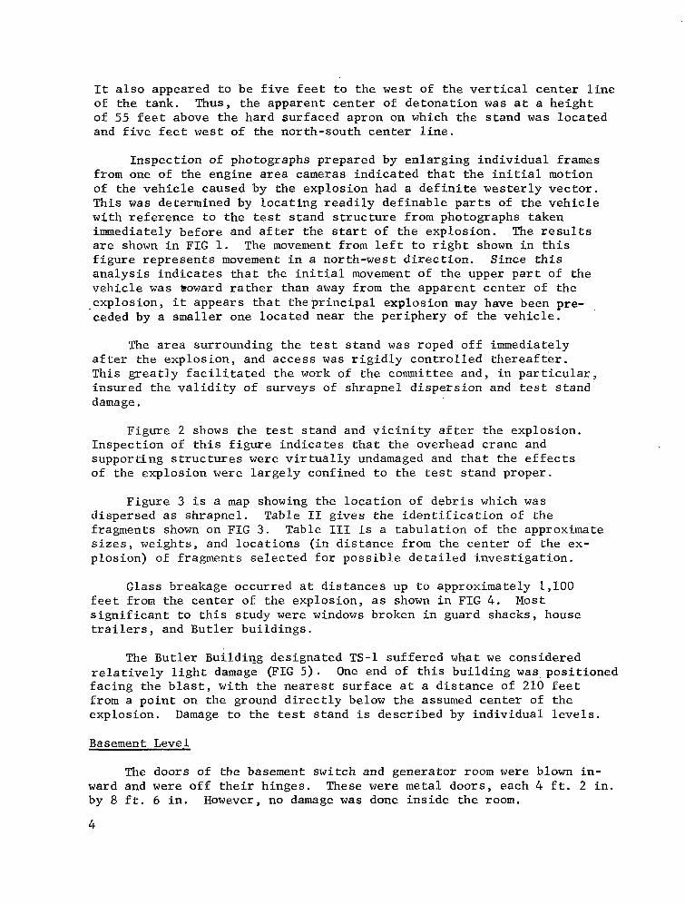
It a l s o a p p e a r e d t o b e f i v e f e e t t o t h e west of t he ver t ica l c e n t e r l i n e of the tank. Thus, the apparent center of de tona t ion was a t a he igh t of 55 feet above the hard surfaced apron on which the s tand was loca ted and f i v e f e e t west o f t he no r th - sou th cen te r l i ne .
Inspect ion of photographs prepared by en larg ing ind iv idua l f rames from one of the engine area cameras ind ica ted tha t the in i t ia l mot ion of the vehic le caused by the explosion had a d e f i n i t e w e s t e r l y v e c t o r . This was determined by l o c a t i n g r e a d i l y d e f i n a b l e p a r t s of t h e v e h i c l e w i t h r e f e r e n c e t o t h e t es t s tand s t ruc ture f rom photographs t aken immediately before and after the s t a r t of the explosion. The r e s u l t s a r e shown i n FIG 1. The movement from l e f t t o r i g h t shown i n t h i s f i g u r e r e p r e s e n t s movement i n a n o r t h - w e s t d i r e c t i o n . S i n c e t h i s a n a l y s i s i n d i c a t e s t h a t t h e i n i t i a l movement of t he uppe r pa r t of t he v e h i c l e was Poward r a the r t han away from the apparent center of the explosion, i t appears tha t thebr inc ipa l explos ion may have been pre- ceded by a smaller one located near the per iphery of the vehicle .
The area surrounding the t es t s tand was roped off immediately a f t e r t h e e x p l o s i o n , and access was r i g i d l y c o n t r o l l e d t h e r e a f t e r . T h i s g r e a t l y f a c i l i t a t e d t h e work of the commit tee and, in par t icular , insured the va l id i ty o f surveys o f shrapnel d i spers ion and tes t s tand d ama ge .
Figure 2 shows the t es t s t and and v i c in i ty a f t e r t he exp los ion . In spec t ion of t h i s f i g u r e i n d i c a t e s t h a t t h e o v e r h e a d c r a n e and s u p p o r t i n g s t r u c t u r e s were v i r t u a l l y undamaged and t h a t t h e e f f e c t s of the explosion were l a rge ly conf ined t o t he tes t s tand proper .
F igure 3 i s a map showing the loca t ion of debr i s which was d ispersed as shrapnel . Table I1 g i v e s t h e i d e n t i f i c a t i o n of the fragments shown on FIG 3 . Table I11 i s a t a b u l a t i o n of the approximate s i zes , we igh t s , and loca t ions ( i n d i s t ance f rom the cen te r of the ex- p los ion) o f f ragments se lec ted for poss ib le de ta i led inves t iga t ion .
Glass breakage occurred a t d i s t a n c e s up to approximate ly 1,100 f e e t from the center of the explosion, a s shown i n FIG 4. Most s i g n i f i c a n t t o t h i s s t u d y were windows broken in guard shacks, house t r a i l e r s , and Bu t l e r bu i ld ings .
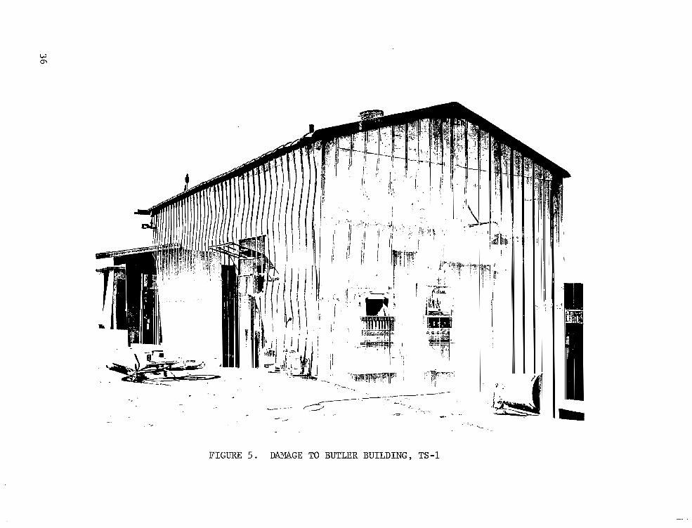
The Butler BuildiQg designated TS-1 suffered what w e considered r e l a t i v e l y l i g h t damage ( F I G 5 ) . One end of t h i s b u i l d i n g was, pos i t ioned f a c i n g t h e b l a s t , w i t h t h e n e a r e s t s u r f a c e a t a d i s t a n c e of 210 f e e t from a point on the ground direct ly below the assumed cen te r of the explosion. Damage t o t h e tes t s tand i s descr ibed by i n d i v i d u a l l e v e l s .
Basement Level
The doors of the basement switch and generator room were blown i n - ward and were o f f t he i r h inges . These were metal doors, each 4 f t . 2 i n . by 8 f t . 6 i n . However, no damage was done i n s i d e t h e room.
4

Level No. 1
The e leva tor car exper ienced some deformation of the roof down- ward, and one sheet metal panel of the roof was peeled upward. There had been a small f i r e i n t h e e l e v a t o r . The double metal doors (4-1/2.11 by 8 ' 6 " ) of the t e rmina l room were blown inward, one being blown o f f i t s hinges. A cab ine t was h i t by the door , and t h i s , i n tu rn , jammed a desk. Otherwise, there was no apparent damage i n t h e t e r m i n a l room.
The ga lvanized i ron roof over the stair landing between levels 1 and 2 was deformed, and p a r t was blown-off.
Level No. 2 (F i r ing Level )
Much debr i s had , fa l len f rom above , bu t there was l i t t l e damage t o t h e s t a n d a t t h i s level. There had been some f i re because f lammable items were s inged. It appeared tha t d rople t s of l i q u i d oxygen had sprayed t h e a r e a s i n c e p a i n t on the s teel was c h a r r e d i n a d r o p l e t p a t t e r n . However, t he s teel had not been heated appreciably.
Some exposed wiring a t the south end of t he l eve l was badly charred. Liquid oxygen had apparently f lowed over the south concrete deck.
Level No. 3
There was r e l a t i v e l y l i t t l e d e b r i s a t t h i s l e v e l . Exposed wir ing was cha r red i n many i n s t a n c e s , and e l e c t r i c a l power c a b l e s i n t h e v e r t i c a l cab le duc t had cha r red i n su la t ion . A l i gh twe igh t shee t me ta l a i r duc t was smashed. The s t r u c t u r e , however, was e s s e n t i a l l y undamaged. Pa in t was cha r red i n a drople t pa t te rn , p resumably because o f l iqu id oxygen spray , bu t the metal had not been heated appre.ciably.
The l i q u i d oxygen s led d id no t appear damaged. On t h e l i q u i d hydrogen s l e d , flammable foam i n s u l a t i o n was burned and valve handles were singed, but damage appeared inconsequential (FIG 6 ) .
Level No. 4
The cableways, made of l ightweight metal , were to rn l oose and dis tor ted; exposed wires were charred. The power c a b l e s i n t h e v e r t i c a l cab le duc t were char red . A few l i g h t f i x t u r e s were knocked o f f t h e i r condui ts . There were f i r e marks on pa in ted steel , apparent ly due to l i q u i d oxygen d r o p l e t s , b u t t h e s tee l had no t been hea t ed s ign i f i - c a n t l y ; t h e r e d i d n o t a p p e a r t o b e s i g n i f i c a n t s t r u c t u r a l damage.
The ' l i qu id oxygen f l e x i b l e f i l l l i n e was burned through a t a poin t wes t o f the vehic le loca t ion and overhead. Thi,s l i n e was p a r t l y p r o t e c t e d by s t r u c t u r e and p ip ing , and i t appea red t ha t t he l i ne had exploded internally. About 10 inches o f l ine was missing; ends were burned, and e x t e r i o r b r a i d was folded back.
5

The conso le s l oca t ed t o t he wes t s ide had been blown p a r t i a l l y over and had suffered ra ther extensive damage a l though there had no t been much f i re . However, the g lass covers on pressure gauges were n o t broken. The roof panel over the console had been blown down onto the console .
There was much.debris f rom the vehicle on the deck and pi led on top of the engines, which a t f i r s t g l a n c e gave the impression that t h i s l e v e l was in shambles . However, s t r u c t u r a l damage was s l i g h t , and f i r e damage was t h a t which would be expected from a r a t h e r h o t , s h o r t - duration exposure, which charred f lammables but did not heat metal unduly (FIG 7 ) .
Level No. 5
Inspec t ion of t h i s l e v e l s u g g e s t e d t h a t t h e e x p l o s i o n c e n t e r e d on t h i s l e v e l , p r o b a b l y a few f e e t above the deck and near the west s ide of the vehicle . There was a cons iderable amount of s t r u c t u r a l damage above the deck. Safety rail ings were torn-off and thrown away. Horizontal wide f lange I beams were ben t ho r i zon ta l ly , and some were torn loose. These beams had been located 10-20 feet above the deck, and deformations ranged up to abou t 2 f e e t i n a 20-foot length (FIG 8 ) .
V e r t i c a l columns were a l s o deformed, although to a much lesser extent because they were of heavier sec t ion .
The a i r -condi t ioned ins t rument room a t the west s i d e was demolished by what appeared to be an internal explosion. The v e r t i c a l power cable duc t was badly deformed and broken open, and cable insulation was charred badly. The e l e v a t o r s h a f t g r i l l e was blown i n , l i g h t s were broken, and conduits were broken off their supports. There were no l i g h t w e i g h t g u t t e r s l e f t . I n s t r u m e n t a t i o n c a b i n e t s on the east were severely burned on the ou t s ide , had opened, and suffered some i n t e r n a l f i r e damage.
There was much debr i s f rom the vehic le on t h i s d e c k a l s o , and some of the decking had been weakened. Many of the t reads on the s ta i rs l e a d i n g t o l e v e l 6 were bowed upward, and some were p a r t i a l l y cut by fragments.
Level No. 6
S t r u c t u r a l members a t t h e d e c k l e v e l and above appeared t o be undeformed excep t fo r one l i g h t h o r i z o n t a l beam a t t h e n o r t h e n d . The nor thwes t h inged f loor g ra t ing was wedged i n t o a p a r t i a l l y r a i s e d p o s i t i o n by debr i s , wh i l e t he no r theas t one was suppor ted in a r a i s e d p o s i t i o n by in t e r f e rence w i th a r a i l i n g p l a t e . Some o f t he gua rd r a i l s were bent . The door t o t h e room a t t h e w e s t s i d e had been blown open, and the window opposite the door was blown out; however, there appeared
6

t o b e l i t t l e damage t o t h e walls. The l a t t e r appeared to be 1/4- inch s t e e l and to have deformed perhaps one inch i n 4-fOOt spank. No f i r e damage was appa ren t w i th in t he room even though papers were exposed.
Level No. 7 and Above
The shed on top of the elevator, which was covered with corrugated s h e e t i r o n , had su f fe red some b l a s t damage; t he shee t metal was ben t and was r o l l e d - u p o r t o r n l o o s e i n p l a c e s . The v e r t i c a l c a b l e d u c t was deformed and blown open (FIG 9) .
There appeared to be no other damage of consequence except that t h e g l a s s windows in the crane cab were broken.
SIGNIFICANCE OF FINDINGS WITH RESPECT TO MAGNITUDE OF EXPLOSION
S e v e r a l d i f f e r e n t e s t i m a t e s of equiva len t explos ive weight were obtained by cons ider ing damage t o s p e c i f i c s t r u c t u r e s . It i s noted t h a t t h e p a r t i c u l a r s t r u c t u r e s s e l e c t e d f o r a n a l y s e s are of widely d i f f e ren t t ypes , r e spond ing t o va ry ing cond i t ions o f l oad - t ime h i s to r i e s , and t h a t t h e e s t i m a t e s of y ie ld requi red to p roduce the damages obtained may consequent ly vary considerably. A t t h e f a r t h e r d i s t a n c e s , a n o v e r - p r e s s u r e c r i t e r i o n may more n e a r l y r e p r e s e n t t h e c r i t e r i o n of f a i l u r e . A t t he i n t e rmed ia t e d i s t ances , damage becomes more a func t ion of a combination of overpressure and posit ive impulse; while a t the very c lose - in d i s t ances , an impu l se c r i t e r ion may be assumed to govern. I n a r r i v i n g a t t h e f o l l o w i n g e s t i m a t e s of y i e l d , t h e s e c r i t e r i a h a v e been assumed and judgments have been made from experience gained in c o r r e l a t i n g t h e damages f rom th i s acc ident wi th those on similar s t ruc tures f rom known e x p l o s i v e q u a n t i t i e s .
Est imate of Explosive Weight Based on Damage t o TS-1 Bu t l e r Bu i ld ing
This bu i ld ing was a l igh tweight shee t metal s t ructure measuring 20' x 48' x 15'. It was pos i t ioned end-on to the d i rec t ion of b las t w i th t he nea res t end s u r f a c e a t a d i s t a n c e of 210 f e e t from a p o i n t on the ground directly below the assumed center o f de tona t ion .
Damage sus t a ined by the But le r bu i ld ing was cons idered to be re- l a t i v e l y l i g h t . The most extensive damage occurred on the end f a c i n g t h e b l a s t , which would have been within the Mach stem. A genera l d e s c r i p t i o n of the damage would inc lude a w r i n k l i n g t o a s l i g h t c r u s h i n g of the corrugated s tee l panels of f rom four to s ix i n c h e s i n b o t h t h e s i d e w a l l s and roo f . Seve ra l windows were broken on the s ides rece iv ing the more d i r e c t b l a s t , b u t o n l y one was broken on e i ther of t he o the r two s i d e s . S e v e r a l s t r u c t u r a l members i n t h e r o o f were s l igh t ly buck led o r de f l ec t ed a maximum of two i nches wh i l e s eve ra l o the r s were loosened a t t h e j o i n t s .

It has been assumed t h a t a r e f l ec t ed ove rp res su re of n e a r l y f i v e p s i would be necessary a t the near end of the bu i ld ing to p roduce damage o f t h i s ex t en t f rom a r e l a t i v e l y s h o r t ( s o m e t h i n g l e s s t h a t 50 mi l l i s econds ) du ra t lon b l a s t wave. The s ide-on overpressure a t the nea r end of t h e b u i l d i n g would then be approximately 2 . 5 p s i and would r e q u i r e a high explosive weight of approximately 760 pounds.
Estimate of Explosive Weight Based on Damage t o Cover P r o t e c t i v e Assembly
The Cover P r o t e c t i v e Assembly was a t runca ted cone l ike s t ruc tu re (FIG 10) fabricated f rom aluminum, es t imated to be approximate ly 1 /16 inch th ick . I t s base diameter was 1 2 f e e t , and i t t a p e r e d t o a top-opening diameter o f f o u r f e e t . I n a l l , t he re were 12 pane ls fas tened to l ong i tud ina l s t i f f e n e r s . The h e i g h t of the s t ruc ture was approximately s ix f e e t . The cover was pos i t ioned face down wi th i t s cen te r 125 f e e t from a p o i n t on the ground beneath the explosion center. Permanent inward crushing, t o a depth of s i x i n c h e s , was observed in several of the pane ls fac ing t h e b l a s t .
The estimate of explosive weight required to produce such damage was made by us ing damage threshold curves similar to t hose g iven i n BRL Memorandum Report 1461 bu t r ev i sed t o i nc lude r ecen t da t a . Fo r ana lys i s , the cover assembly was t r e a t e d a s a r i g h t c i r c u l a r c y l i n d e r w i th t he fo l lowing cha rac t e r i s t i c s : l eng th , 6 f ee t ; d i ame te r , 1 2 f e e t ; sk in t h i ckness , 0.062 incli; material, aluminum, It was f u r t h e r assumed t h a t t h e s t i f f e n e r s i n c r e a s e d by l 0 , p e r c e n t t h e o v e r p r e s s u r e r e q u i r e d for c rush ing . The a n a l y s i s shows that an explosive charge of TNT weighing 1,200 pounds woul'd be required to produce approximately the same degree of damage. The ana lys i s a l so i nc ludes t he a s sumpt ion t ha t t h e s t r u c t u r e would have been i n t h e Mach stem p o r t i o n of t h e b l a s t wave.
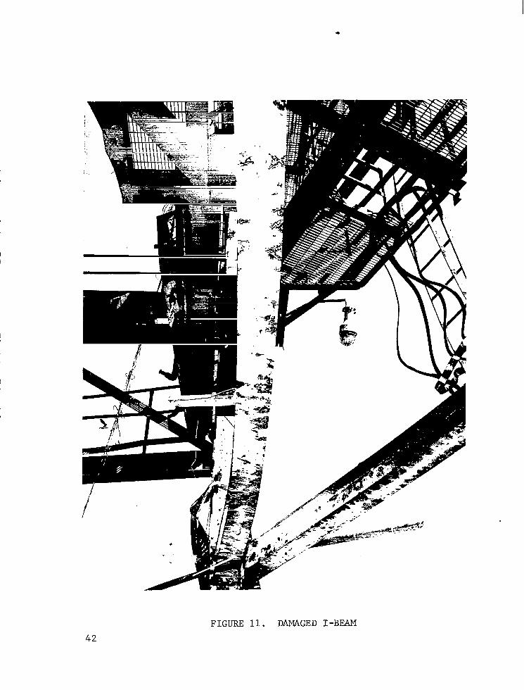
Estimate of Explosive Weight Based on Damage t o I-Beams
The beam chosen for ana lys i s (FIG 11) was t h e h o r i z o n t a l s t r u c t u r a l member (8WF 17 I-Beam, 25 f e e t l o n g ) , l oca t ed on the no r th s ide of t h e t e s t s tand a t level 5 . All t he ho r i zon ta l members a t t h i s l e v e l were damaged, as were some a t the nex t h ighe r l eve l , 10 fee t above . This beam was s e l e c t e d f o r a n a l y s i s s i n c e i t s permanent def lect ion was apprec iab ly more t h a n a l l o w a b l e i n t h e e l a s t i c r a n g e w i t h o u t e x c e s s i v e b u c k l i n g . The beams on t h e west s i d e were sheared from the ver t ica l member and s e v e r e l y d i s t o r t e d and buckled. The permanent deformation of the ho r i zon ta l beam on t h e e a s t s i d e was cons idered to be too near ly the maximum a l l o w a b l e e l a s t i c d e f l e c t i o n a n d , t o some e x t e n t , was sh ie lded by the tank f rom the .explosion center .
To a r r ive t o an e f f ec t ive we igh t based on beam damage, an ana lys i s based on work by Nor r i s , e t a l . , of t he Massachuse t t s In s t i t u t e of Technology (Ref. 2) was employed. The method involves t ransforming the
8

a c t u a l beam system into an ideal ized mass-on-spring, s ingle-degree of f reedom system. Certain t ransformation factors are appl ied, and the system i s ana lyzed i n t he p l a s t i c r ange .
To per form the ana lys i s , ce r ta in assumpt ions concern ing the loading had t o be made. For s impl i c i ty , t he beam was cons idered to be simply supported and uniformly loaded. In actuali ty, the beam was f i x e d t o t h e v e r t i c a l columns and was probably not loaded uniformly s ince one end was s e v e r a l f e e t c l o s e r t o t h e a p p a r e n t c e n t e r of explosion than the o ther . It was a l s o assumed tha t t he l oad ing was impulsive wi th a pos i t ive dura t ion approximate ly 1 /20 the na tura l per iod of the beam. The beam was considered loaded in the s t rong direct ion; however , observa t ions showed t h a t some load ing a l so occu r red i n t he weak d i r e c t i o n .
Based on the permanent def lect ion of approximately 1 2 i n c h e s a t t h e center of the beam and a d i s t ance of 1 3 f e e t from the center of explos ion to t he beam c e n t e r , i t i s e s t ima ted t ha t a high explosive weight of
. 1,000 pounds would be required to produce such damage. This i s be- l i e v e d t o be an upper bound on the explosive weight needed to produce
' such a deformation based on t h i s a n a l y s i s . It i s t o be noted that de- formation i s based on the magnitude of impulse associated with 1,000 pounds of high explosive and t h a t t h e c h a r a c t e r i s t i c p r e s s u r e - t i m e h i s t o r y of the fuel explosion and h i g h e x p l o s i v e a t t h i s d i s t a n c e may b e q u i t e d i f f e r e n t
Estimate o f Explo-sive .. . Weight Based on Glass Damage
Before a t tempting to judge the s ize of the explosion from the g l a s s b r e a k a g e , d i f f i c u l t i e s i n h e r e n t i n t h i s method of e s t ima t ion should be pointed out.
The f i r s t c a u s e f o r c o n c e r n i s tha t t he r ange of p re s su res r e - qu i red to b reak windows i s r e l i ab ly r epor t ed t o r ange from 0 . 1 t o 2 . 0 ps i , depending upon t h e s i z e , t h i c k n e s s , and mounting of the glass. The damage done t o t h e windows o f t h e l a r g e d o u b l e t r a i l e r a t t h e t e s t s i t e i s a pe r fec t ca se i n po in t . The re were th ree ident ica l windows on the s ide fac ing the explos ion . Each had two panes, one f ixed and one ho r i zon ta l ly s l i d ing . In each ca se , t he f i xed g l a s s was broken. Thus, a t f i r s t g l a n c e one might conc lude tha t the t ra i le r was a t the exac t "average" dis tance for glass breakage s ince exact ly half the panes were broken. However, c lose r i n spec t ion showed tha t the f ixed panes were h e l d i n t h e i r aluminum frames by p l a s t i c s t r i p s and glue, whereas the movable panes were s e t i n r u b b e r . I n o t h e r w o r d s , t h e f i x e d panes broke because they were inherently more suscep t ib l e t o b reakage .
The second r eason fo r cau t ion i n u s ing t h i s method of a s ses s ing b l a s t y i e l d i s tha t co r re l a t ions fo r g l a s s b reakage t ake t he fo rm:
9

Here, d i s the average d i s tance for g lass b reakage; W the weight of explosive, and K i s a constant . Thus, an es t imate of W from d involves (d/K)3, so t h e r e s u l t i s ex t r eme ly s ens i t i ve t o t he poor ly de f ined parameter d .
Subjec t t o t he fo rego ing r e se rva t ions , i t i s p o s s i b l e t o g e t a n es t imate of t h e y i e l d . I n s p e c t i o n of a l l a v a i l a b l e d a t a i n d i c a t e d tha t t he ana lys i s p robab ly shou ld be r e s t r i c t ed t o ev idence f rom on ly two s i tes of g lass b reakage .
a . A l l the window panes fac ing the cen ter of t h e ‘ b l a s t were broken in the guard house , 5 4 0 f e e t from the explosion.
b . Of the 18 panes i n t h e pump house t h a t were r o u g h l y i n l i n e - o f - s i g h t , s i x were broken, 700 f e e t from the explosion.
A t both locat ions, the panes were of the same th ickness and were s i m i l a r i n s i z e ; some of them were glazed i n a s imi l a r f a sh ion .
These da ta ind ica te tha t the average d i s tance for g lass b reakage , i . e . , t he d i s t ance a t which about half the glass would have been broken, was between 5 4 0 and 700 f e e t . An appropr ia te formula to use i s a s fol lows :
Using a va lue of 6 2 0 f e e t f o r d , which corresponds to a po in t loca ted halfway between the two s t r u c t u r e s , W i s e s t ima ted t o be about 1,400 pounds. This corresponds to a s ide-on pressure of about 0 . 7 p s i a t 620 f e e t , which i s within the expected range.
Est imate of Explosive- Keight Based on Fragnent~_Disp_ersio-n
Fragment dispers ion data can be used to obtain an es t imate of equivalent weight of explosive i f information i s ava i l ab le fo r t he d i s t ance t r ave led , c ros s s ec t iona l a r ea , we igh t , and d r a g c o e f f i c i e n t of individual f ragments , and a l s o f o r t h e v e l o c i t y and d i r e c t i o n of the prevai l ing winds a t the time of the explosion. For the S-IV A l l Systems Vehicle explosion, se lected f ragments were weighed and measured. Drag c o e f f i c i e n t s were estimated based on the following assumptions:
a . P l a t e s were cons idered to be rec tangular in shape , re la t ive ly t h i n , and s u b s t a n t i a l l y f l a t . The f l i g h t a t t i t u d e was taken t o be normal t o t h e t r a j e c t o r y f o r 213 of the distance. These assumptions led to the fo l lowing:
cD assumed 2 / 3 c~ normal
A assumed - A normal -
10

b. Cyl inders were cons ide red t o be so l id and t o tumble so t h a t 112 of f l i g h t was i n normal and 112 i n a x i a l a t t i t u d e . These assumptions .led to t he fo l lowing :
E cD ax la1 + cD normal assumed 2
- A assumed - A a x i a l + A normal
2
c. Rectangular blocks were approximated by cubes which were assumed t o tumble i n f l i g h t . These assumptions led to the following:
assumed CD normal
A assumed = A normal
Ex t reme ly l imi t ed i n fo rma t ion i nd ica t ed t ha t , a t t he time of the explosion, the wind a t ground l e v e l was from the southwest a t r o u g h l y 8 t o 1 2 knots . N o information was a v a i l a b l e f o r a l t i t u d e s g r e a t e r than 100 f e e t .
F igures 12 and 1 3 i n d i c a t e t h e r e l a t i o n b e t w e e n i n i t i a l v e l o c i t y and d i s t ance t r ave led fo r f r agmen t s o f d i f f e ren t d rag coe f f i c i en t s , c ros s s e c t i o n a l a r e a s , and weights using an assumed f l i g h t a n g l e of 4 5 " . Table I V g i v e s t h e i d e n t i t i e s and p e r t i n e n t d a t a f o r s e l e c t e d f r a g m e n t s from the S-IV A l l Systems Vehicle explosion and i n i t i a l v e l o c i t i e s estimated from F I G 1 2 and 13.
To obta in an es t imate o f equiva len t explos ive weight , the in i t ia l v e l o c i t i e s g i v e n i n T a b l e I V were compared wi th unpubl i shed da ta for f r agmen t s r e su l t i ng from explosions involving known weights of high explosive. For American 2,000-pound general purpose bombs conta in ing approximately 1 ,100 pounds of high explosives , secondary s t ructural fragments had i n i t i a l v e l o c i t i e s g e n e r a l l y w i t h i n i 2 0 p e r c e n t of those c a l c u l a t e d f o r s e l e c t e d S-IV A l l Systems Vehicle fragments having similar d rag coe f f i c i en t s . Fo r American 1,000-pound bombs conta in ing 530 pounds of high explosives, secondary structural fragments had i n i t i a l veloci t ies appreciably lower (approximately 40 percent ) than those for S-IV A l l Sys tems Vehic le f ragments wi th s imi la r d rag coef f ic ien ts . Therefore , a va lue of approximately 1,100 pounds of TNT i s t aken fo r comparison with the other es t imates .
The lack of p rec ise wind da ta and the necessi ty for assuming a 45" a n g l e o f f l i g h t g r e a t l y l i m i t the va lue of e s t ima tes of equiva len t explosive weights based on f ragment d i spers ion pa t te rns . The r e s u l t of t h i s a n a l y s i s of se lec ted f ragments , therefore , i s included only because it tends to conf i rm the estimates obtained by other methods.
11
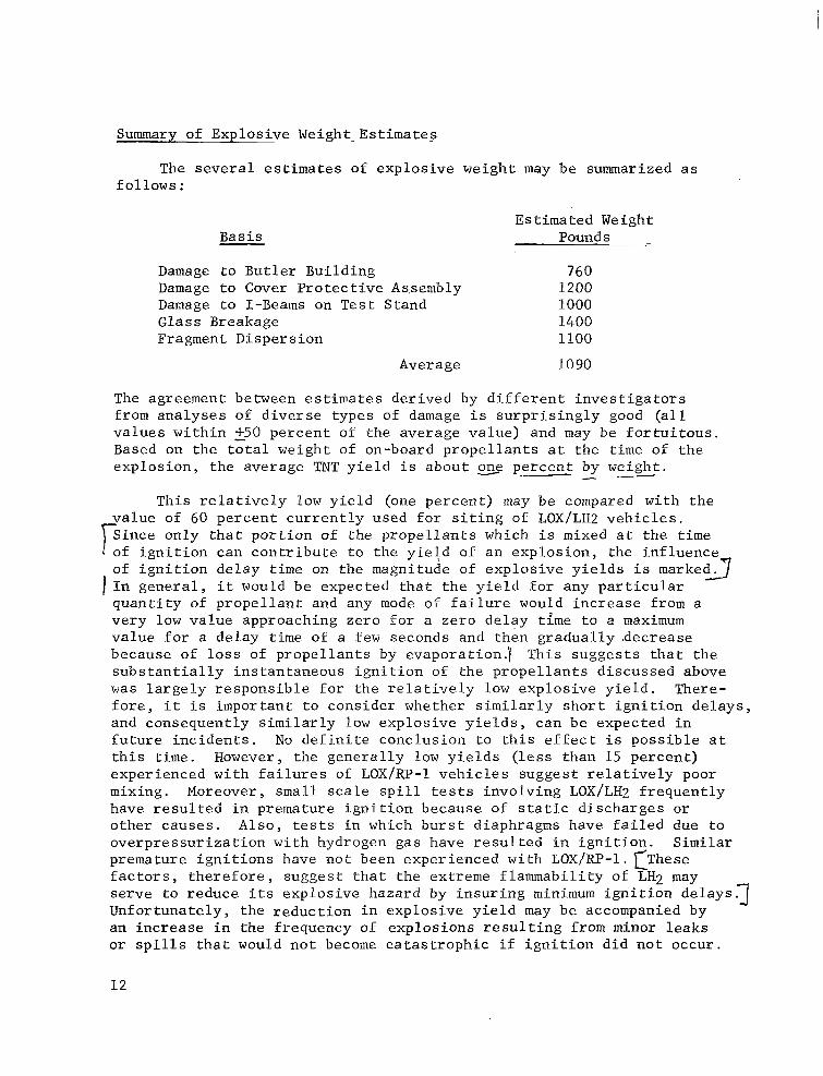
Summary of- Explosive Weight. Es t imates
The seve ra l e s t ima tes of explosive weight may be summarized as fo l lows :
Basis
Damage to Bu t l e r Bu i ld ing Damage t o Cover P ro tec t ive As,sembly Damage t o I-Beams on Test Stand Glass Breakage Fragment Dispersion
Estimated Weight Pounds -
760 1200 1000 1400 1100
Average 1090
The agreement between estimates derived by d i f f e r e n t i n v e s t i g a t o r s from analyses of diverse types of damage i s s u r p r i s i n g l y good ( a l l va lues wi th in 250 percent of the average value) and may be f o r t u i t o u s . Based on t h e t o t a l w e i g h t of on-board propellants a t the time of the explosion, the average TNT y i e l d i s about =e percent by weight.
”-
T h i s r e l a t i v e l y low y i e l d (one percent ) may be compared with the va lue of 60 p e r c e n t c u r r e n t l y u s e d f o r s i t i n g of LOX/LH2 v e h i c l e s . Since only that por t ion of the propel lants which i s mixed a t t h e time of i gn i t i on can con t r ibu te t o t he y i e td of an explosion, the inf luence of i g n i t i o n d e l a y time on the magnitude of explosive yields i s m a r k e d 3 I I n gene ra l , i t would be expec ted tha t the y ie ld for any par t icu lar quan t i ty of p rope l l an t and any mode of f a i l u r e would inc rease from a very low value approaching zero for a zero de lay t ime to a maximum v a l u e f o r a delay time of a few seconds and then gradually ,decrease because of loss of p rope l l an t s by evapora t ion . ) This sugges ts tha t the subs t an t i a l ly i n s t an taneous i gn i t i on of the propel lants discussed above was l a r g e l y r e s p o n s i b l e f o r t h e r e l a t i v e l y low explos ive y ie ld . There- f o r e , i t i s impor tan t to cons ider whether s imi la r ly shor t ign i t ion de lays , and consequent ly s imi la r ly low explos ive y ie lds , can be expec ted in f u t u r e i n c i d e n t s . No d e f i n i t e c o n c l u s i o n t o t h i s e f f e c t i s p o s s i b l e a t t h i s t i m e . However, the genera l ly low y i e l d s ( l e s s t h a n 15 percent ) expe r i enced w i th f a i lu re s of LOX/RP- l v e h i c l e s s u g g e s t r e l a t i v e l y poor mixing . Moreover , smal l sca le sp i l l t es t s involv ing LOX/LH2 f r equen t ly have r e su l t ed i n p rema tu re i gn i t i on because o f s t a t i c d i scha rges o r other causes . Also , t e s t s i n which burst diaphragms have failed due to overpressur iza t ion wi th hydrogen gas have resu l ted in ign i t ion . S imi la r premature ignitions have not been experienced with LOX/RP-1. EThese fac tors , therefore , sugges t tha t the ex t reme f lammabi l i ty o f LH2 may serve to reduce i t s explosive hazard by in su r ing minimum i g n i t i o n d e l a y s Unfor tuna te ly , the reduct ion in explos ive y ie ld may be accompanied by an increase in the f requency of explosions resul t ing f rom minor l eaks o r s p i l l s t h a t would n o t become c a t a s t r o p h i c i f i g n i t i o n d i d n o t o c c u r .
r
1
1 2
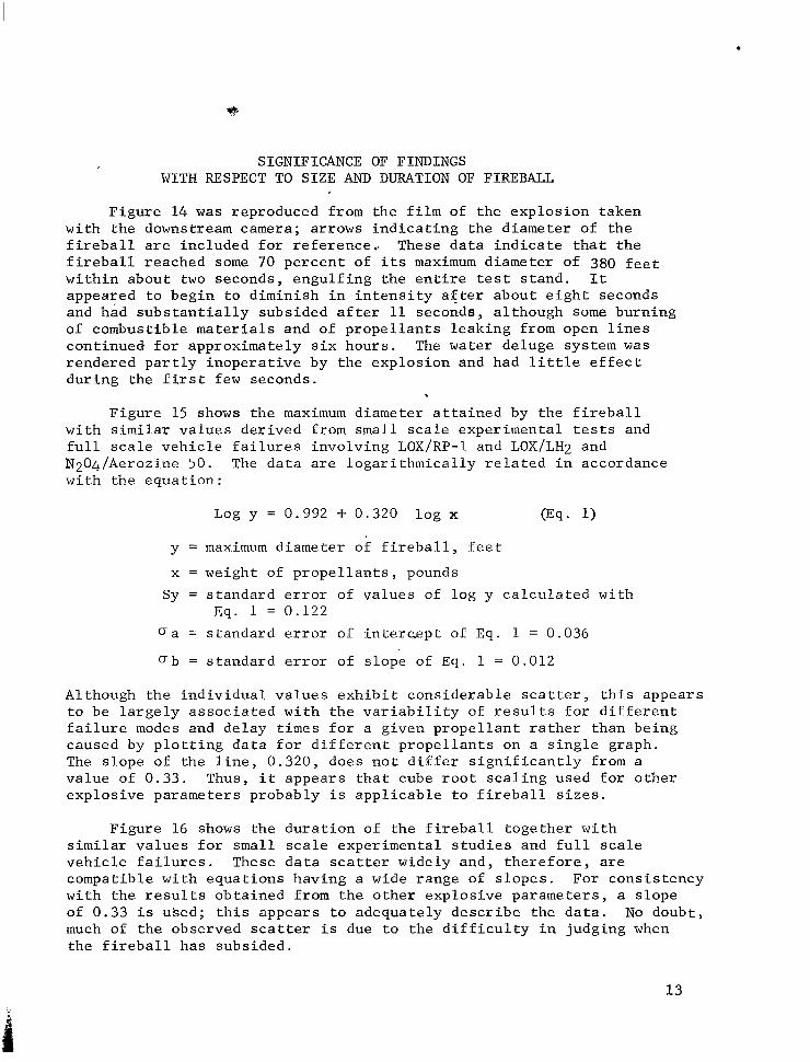
SIGNIFICANCE OF FINDINGS WITH RESPECT TO SIZE AND DURATION OF FIREBALL
Figure 14 was reproduced from the f i lm of the explos ion taken with the downstream camera; arrows indicating the diameter of the f i r e b a l l a r e i n c l u d e d f o r r e f e r e n c e . . These d a t a i n d i c a t e t h a t t h e f i r e b a l l r e a c h e d some 70 pe rcen t of i t s maximum diameter of 380 f e e t wi th in about two seconds , engul f ing the en t i re t e s t s tand . It appea red t o beg in t o d imin i sh i n i n t ens i ty a f t e r abou t e igh t s econds and had s u b s t a n t i a l l y s u b s i d e d a f t e r 11 seconds, al though some burning of combustible materials and of propel lan ts l eak ing f rom open l ines cont inued for approximate ly s ix hours . The water deluge system was r ende red pa r t ly i nope ra t ive by the explosion and had l i t t l e e f f e c t d u r i n g t h e f i r s t few seconds.
Figure 15 shows the maximum diameter a t ta ined by t h e f i r e b a l l wi th s imi la r va lues der ived f rom smal l sca le exper imenta l t es t s and f u l l s c a l e v e h i c l e f a i l u r e s i n v o l v i n g LOX/RP-1 and LOX/LH2 and N204/Aerozine 50. The da ta a r e l oga r i thmica l ly r e l a t ed i n acco rdance wi th the equat ion:
Log y = 0.992 + 0.320 log x
y = maximum d i a m e t e r o f f i r e b a l l , f e e t
x = weight of p r o p e l l a n t s , pounds Sy = s t anda rd e r ro r of values of log y ca l cu la t ed w i th
Eq. 1 = 0 . 1 2 2 (sa = s t anda rd e r ro r of i n t e r c g p t of Eq. 1 = 0.036
Ob = s tandard e r ror o f s lope of Eq. 1 = 0.012
Al though t he i nd iv idua l va lues exh ib i t cons ide rab le s ca t t e r , t h i s appea r s t o be l a rge ly a s soc ia t ed w i th t he va r i ab i l i t y of r e s u l t s f o r d i f f e r e n t f a i l u r e modes and de lay t imes for a g iven p rope l l an t r a the r t han be ing caused by p l o t t i n g d a t a f o r d i f f e r e n t p r o p e l l a n t s on a s ing le g raph . The s lope o f t he l i ne , 0 .320 , does no t d i f f e r s ign i f i can t ly from a value of 0.33. Thus, i t appears that cube root scal ing used for other explosive parameters probably i s a p p l i c a b l e t o f i r e b a l l s i z e s .
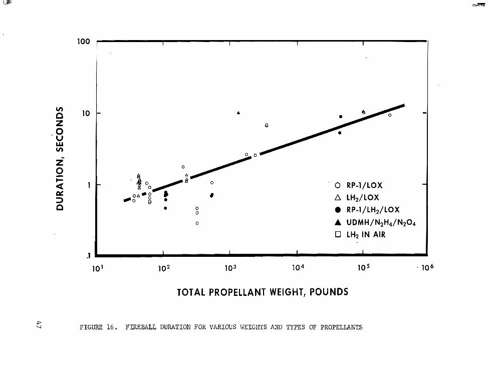
Figure 16 shows the du ra t ion of t h e f i r e b a l l t o g e t h e r w i t h s i m i l a r v a l u e s f o r small sca le exper imenta l s tud ies and f u l l s c a l e v e h i c l e f a i l u r e s . These d a t a scat ter wide ly and , therefore , are compatible with equat ions having a wide range of slopes. For consistency wi th t he r e su l t s ob ta ined f rom the o the r exp los ive pa rame te r s , a s lope of 0.33 i s uked; t h i s appea r s t o adequa te ly desc r ibe t he da t a . No doubt , much of t he obse rved s ca t t e r i s due t o t h e d i f f i c u l t y i n j u d g i n g when t h e f i r e b a l l h a s s u b s i d e d .
13

Inspect ion of the tes t s tand and i t s immediate sur@oundings i n d i c a t e d s u r p r i s i n g l y l i t t l e damage due t o f i r e . Moreover, wherever evidence of burning was noted, the extreme lack of uniformity and occurrence of spot ted burning pat terns suggested’ that the dispers ion o f l a r g e q u a n t i t i e s of LOX by the explosion markedly influenced the ex ten t o f damage. More s p e c i f i c a l l y , i t appeared that charr ing of pa in t ed su r f aces was i n many ins t ances con f ined t o a r eas exposed t o LOX. It was of i n t e r e s t t o n o t e some of the items on the var ious leve ls which were no t apprec iab ly a f fec ted by t h e f i r e . Thus, a nylon rope on l e v e l No. 3 showed only one small (1/8-inch diameter) singed area . Scraps of a rubber ized fabr ic used as a r a i n s h i e l d f o r t h e u p p e r l e v e l s were sca t t e red abou t t he t es t stand. Although i t was subsequently found t h a t t h i s m a t e r i a l was badly burned by a 30-second exposure t o a 700°F environment, most of the scraps noted about the t e s t s tand ex- hibi ted only local ized burning or scorching, which suggests that the damage was l i m i t e d t o t h o s e a r e a s c o n t a c t i n g LOX.
Information expected to be derived from the small scale tes t programs should permit an estimate of the temperature of a b lack body r ad ia to r app rox ima te ly equ iva len t t o t he f l ame from a LOX/LH2 explosion Such an e s t ima te coup led w i th t he f i r eba l l du ra t ion w i l l pe rmi t ca l - c u l a t i o n of t h e h e a t f l u x t o a capsule or other exposed object .
SIGNIFICANCE OF EXPLOSION WITH RESPECT TO PROBABILITY OF FUTURE INCIDENTS
Because of the extremely l imited experience, i t i s p o s s i b l e t o cons ider the s ign i f icance of the S-IV A l l Systems Vehicle explosion w i t h r e s p e c t t o t h e p r o b a b i l i t y of f u t u r e i n c i d e n t s f o r LOX/LH2 v e h i c l e s .
The hazard involved in tests wi th ba t t l e sh ip t ankage would be expec ted to be fa r less t h a n t h a t f o r tes ts u s i n g f l i g h t w e i g h t hardware . This d i scuss ion , therefore , i s l i m i t e d t o s t a t i c tes ts and launches of Centaur and S-IV f l i g h t w e i g h t v e h i c l e s . T a b l e V summarizes expe r i ence w i th t hese veh ic l e s t o Apr i l 20, 1964. Although i t i s some- times a rgued t ha t t ank ing ope ra t ions a r e less haza rdous t han s t a t i c f i r i n g s o r l a u n c h e s , i t should be noted that the tanking operat ions occur ear l ie r i n t h e development when t h e v e h i c l e may be cons idered less proven. Also, i t must be emphasized that both the Centaur and the S-IV A l l Systems Vehicle explosions occurred beforeignition.
On t h i s b a s i s , t h e two fa i lures cor respond to approximate ly four percent of the populat ion. Tables given in the appendix of Lloyd and Lipow provide an upper confidence l i m i t f o r t h e p r o b a b i l i t y o f f u t u r e inc iden t s of approximately 16 pe rcen t fo r a conf idence coe f f i c i en t of 0 .99 o r 10 pe rcen t fo r a conf idence coe f f i c i en t of 0 .95 . Therefore , i t appea r s t ha t , even i f t he p robab i l i t y o f fu tu re i nc iden t s i s decreased as a r e s u l t of l ea rn ing , a s u f f i c i e n t number of incidents can be expected t o w a r r a n t c a r e f u l a t t e n t i o n t o r i s k s and t rade-off considerat ions a t t e n d a n t t o s i t i n g of tes t and launch operations.
14

BLAST GAUGES
While examination of the damage resulting from an incident of this type permits a rough estimate of the magnitude of the explosion, a much more quantitative estimate would be possible if blast gauges had been installed at the test site. Inasmuch as this lack of instrumentation resulted in loss of quantitative blast data which probably would cost in excess of one million dollars to duplicate in a controlled experiment, it is considered essential to take additional steps to insure that any future incidents are adequately instrumented.
CONCLUSIONS
The evidence obtained from the different parts of this investigation appears to support the following conclusions:
1. The damage resulting from the S-IV All Systems Vehicle explosion was relatively slight and may be characterized as follows:
Maximum fragment radius 1,500 feet Maximum fireball diameter 380 feet Fireball duration 11 seconds Explosive yield 1 percent
2. The relatively low yield was due to substantially instantaneous ignition of the spilled propellants, which suggests that the extreme flammability of hydrogen may provide generally shorter ignition delays than those experienced with LOX/RP-l for actual vehicle failures. If this trend can be substantiated, some reduction in the 60 percent TNT equivalent currently used for siting of LOX/LH2 vehicles may be possible.
3 . Unfortunately, the extreme flammability of hydrogen may tend to increase the frequency of incidents since small spills or leaks which would otherwise be of no consequence may undergo ignition and lead to catastrophic failure. The loss of two LOX/LH2 vehicles out of 4 9 tanking and firing operations to-date tends to substantiate this possibility.
15

TABLE I
PROPELLANTS AND GASES ON BOARD ALL SYSTEMS VEHICLE AT TIME OF EXPLOSION
LOX Indicated Weight
LH2 Indicated Weight
LOX Tank Pressure
LH2 Tank Pressure
Cold He Bo t t l e P re s su re
Cold He Bottle Temperature
Volume LOX Tank
Volume LH2 Tank
Volume Cold He Sphere (3 requi red)
84,244 Lbs.
16 , 954 Lbs.
100 p s i a - (Approximate)
4 1 p s i a
800 p s i a
Off Scale ( to approx. 25"R)
1 ,263 F t3 ( spec i f i ca t ion va lue )
4 ,197 F t3 ( spec i f i ca t ion va lue )
3 .5 F t each ( spec i f i ca t ion va lue )
16

TABLE I1
IDENTIFICATION OF FRAGMNTS SHOWN ON FIGURE 3
Southwest . . . - . . - Quadrant A-1 216
217 218 21 9 220 221 222 223 2 24
226 227 293 229
A-3 228 231 233 274 291 292
A-2 225
A-5 232 A-6 230
290 261 294
234
296
A-7 295
A- 8
A-9 297 B-4 235 B-8 300 B-9 298 C-2 289 C-4 262 C-5 239
237 273
C-7 236 C-8 656 C-10 659
Fuel Tank Wall LOX Fill Line Elbow or Fuel TK Outlet Elbow to Low Pressure Duct Forward or Aft Interstage Structure Forward or Aft Interstage Structure Fuel Tank Dome Fuel Tank Wall Common Bulkhead Fuel Tank Wall Common Bulkhead Fuel Tank Wall LOX Tank Vent Outlet Elbow Forward or Aft Interstage Structure LOX Tank Vent Outlet Elbow Aft Interstage Structure Aft Interstage Structure Tank Structure Common Bulkhead Joint Fuel Tank Fwd Dome & Wall Section P/N 1A22765-1004 VDA Electrical Assembly Fuel Tank Low Pressure Duct Vehicle Roll Ring Support Lug 38717 (8 or 6) 2 - 401 Fuel Tank Bulkhead Attach Pt. With Vacuum Port Fuel Tank Wall .a Anti Vortex Screen Accel. & Mt. Blk. Accel. S/N EA03 & EA02 Aft Interstage Structure Chilldown Duct Around Vehicle Fuel Tank Structure Lower Skirt Skim Fuel Tank Anti Vortex Screen Fuel Chilldown Doughnut Around Vehicle Fwd. Int/Stg. Bulkhead & T/M & CDR Antenna CDR Cable #4lOWlOpL Chilldown Duct 1A01734-A45-1 Aft Interstage Structure Meter IU Substitute Panel IU Substitute Panel Meter Fuel Tank Structure Interstage Structure Fwd Fuel Tank Accel. & Mt. Blk. FA08 & EA09 Fuel Tank Skin Hyd Tank Skin Skirt Structure
17
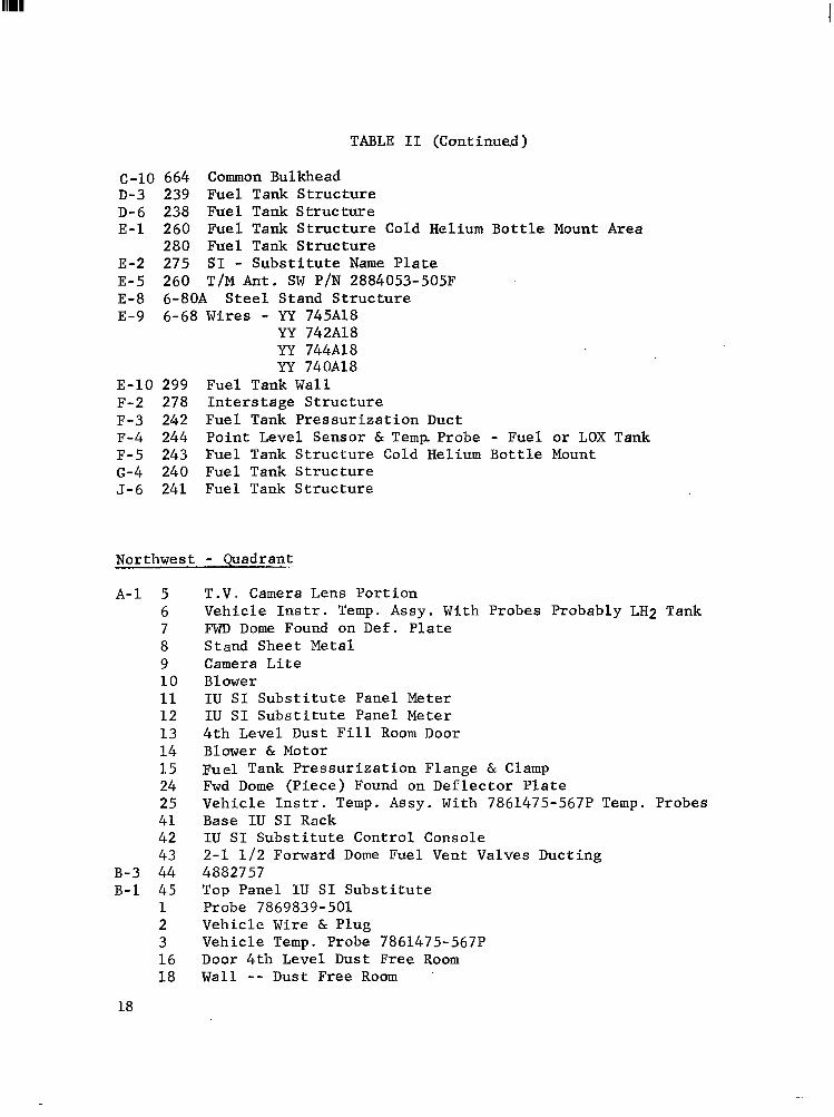
TABLE I1 (Continued)
c-10 664 Common Bulkhead D-3 239 Fuel Tank Structure D-6 238 Fuel Tank Structure E-1 260 Fuel T a d Structure Cold Helium Bottle Mount Area
280 Fuel Tank Structure E-2 275 SI - Substitute Name Plate E-5 260 T/M Ant. SW P/N 2884053-505F E-8 6-80A Steel Stand Structure E-9 6-68 Wires - W 745818
YY 742818 YY 744A18 W 740A18
E-10 299 Fuel Tank Wall F-2 278 Interstage Structure F-3 242 Fuel Tank Pressurization Duct F-4 244 Point Level Sensor & Temp Probe - Fuel or LOX Tank F-5 243 Fuel Tank Structure Cold Helium Bottle Mount 6-4 240 Fuel Tank Structure J-6 241 Fuel Tank Structure
Northwest 7 Quadrant
A-1 5 6 7 8 9 10 11 12 13 14 15 24 25 41 42 43
B-3 44 B-1 45
1 2 3 16 18
T.V. Camera Lens Portion Vehicle Instr. Temp. Assy. With Probes Probably LH2 Tank FWD Dome Found on Def. Plate Stand Sheet Metal Camera Lite Blower IU SI Substitute Panel Meter IU SI Substitute Panel Meter 4th Level Dust Fill Room Door Blower & Motor Fuel Tank Pressurization Flange & Clamp Fwd Dome (Piece) Found on Deflector Plate Vehicle Instr. Temp. Assy. With 7861475-567P Temp. Probes Base IU SI Rack IU SI Substitute Control Console 2-1 112 Forward Dome Fuel Vent Valves Ducting 4882757 Top Panel IU SI Substitute Probe 7869839-501 Vehicle Wire & Plug Vehicle Temp. Probe 7861475-567P Door 4th Level Dust Free Room Wall -- Dust Free Room '
18

TABLE I1 (Continued)
B-1 19 20 21 22 23 34 35 36
A-3 29 30
B-2 7 D-1 27 F-1 28 D-3 4 c-3 39 A-4 31 A-7 40 D-5 37
D-6 38 C-6 32 D-7 26 G-2 26
41 H-1 62 H-2 67 1-3 63 H-3 29
211 65 68
G-4 216 F-5 221 H-5 619 G-5 218 H--5 614 H-6 613 A-7 654
651 B-7 638
,237 636
C-7 660 D-7 639
63 5 631
3871762-4 LH2 Tank
Vehicle Elect. Connector Type T42K 3 x 2 Regulator Face GSE Cable Assembly Cable Assy. GSE Controls GSE Cable Assembly 1734 Chilldown Duct Common Bulkhead 1A76599 Stand Structure 4 x 10 Sheet Metal Interface Purge Duct Vehicle Instr. Temp. Tree Probably LH2 Tank T/M & CDR Antenna P/N 5883605-1-0023 Temp. Probe S/N 1340N Fwd. Interstage Bulkhead (2' x 4') Endevco Accel. 22150-S/N FA05
S/N EA04 Common Bulkhead 3 x 3 LH2 Tank Wall (2' x 4') Fwd Interstage 1 x 1 Plate Vehicle Panel With Weld Bead Tank Skin Tank Skin LH2 Tank Structure Vehicle Body Panel Vehicle Panel Hat Section 1803734 - Vent Duct LH2 Structure Tank Aft Interstage Skirt Tank Skin Aft Interstage Skirt (Outer Surface) LH2 Tank Structure Thrust Struct Skirt LH2 Tank Structure Skirt Structure Lower Skirt Skin LH2 Tank Structure LH2 Tank Structure LH2 Tank Structure Wire Skirt Channel Skirt
P/N 1836695-1
19

TABLE I1 (Continued)
D-7 630 H-7 620 6-7 623 A-8 15.5
249 653
B-8 252 658 657 64 5 641 640
648
166 23 3 2 34
C-8 161
D-8 162
E-8 228 F-8 224
229 G-8 626
627 622
244 64 6
B-9 242 E-9 665 A-10 663 A-13 667 A-14 269 B-15 670 A-15 271 A-16 173 B-16 674 A-17 622 D-20 175 B-22 676 C-22 677 E-30 178
A-9 247
LH2 Tank Structure Skirt Structure Common Bulkhead Flange LH2 Tank Temp. Probe & Support LH2 Vent Line Section Common Bulkhead LH2 Tank Structure Bulkhead LOX LH2 Tank Structure Skirt LH2 Tank Skin LH2 Tank Structure (Large) Aft Skirt Outer Skin Tank Structure Two (2) Pieces LH2 Tank Structure LH2 Tank Structure LH2 Tank Structure LH2 Tank Structure Tank Structure LH2 Tank Structure LH2 Tank Structure LH2 Tank Structure Tank Skin Skirt Structure LH2 Tank Structure Thrust Structure Skirt Member Skirt Structure Tank Structure Skirt Structure Fwd Dome Structure LH2 Tank Structure Common Bulkhead One Face and Honeycomb Common Bulkhead Aft Skirt Piece With Spacer Bolt Aft Skirt Spacer Strip LH2 Tank Insul. Liner Tank Skin Strip - Common Bulkhead Skin LH2 Tank Skin Common Bulkhead Aft Interstage Skirt Section
20
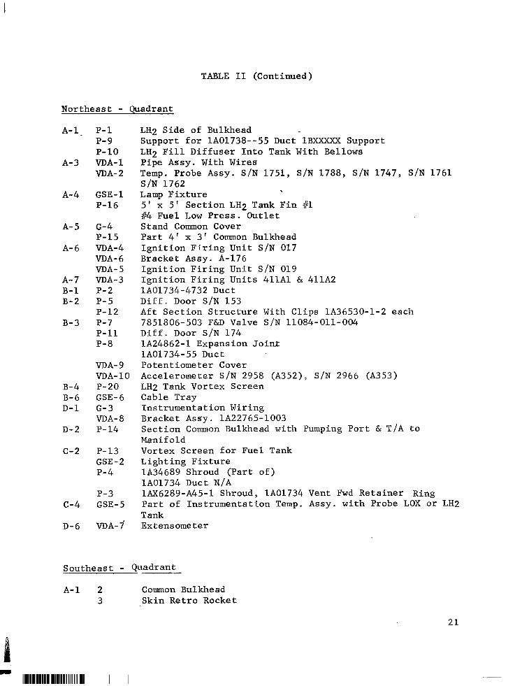
TABLE I1 (Continued)
Northeast . . - Quadrant A-l~
A- 3
A- 4
A- 5
A- 6
A- 7 B-1 B-2
B-3
B-4 B- 6 D- 1
D-2
c-2
c-4
D-6
P- 1 P- 9 P-10 VDA- 1 VDA- 2
GSE - 1 P-16
G-4 P-15 VDA-4 VDA- 6 VDA- 5 VDA- 3 P- 2 P- 5 P-12 P- 7 P-11 P- 8
VDA- 9 VDA- 10 P- 20 GSE- 6 G-3 VDA- 8 P- 14
P- 13 GSE - 2 P-4
P-3 GSE- 5
VDA- 7
LH2 Side of Bulkhead Support for lAO1738--55 Duct 1BXXXX;rS Support LH2 Fill Diffuser Into Tank With Bellows Pipe Assy. With Wires Temp. Probe Assy. S/N 1751, S/N 1788, S/N 1747, S/N 1761 S/N 1762 Lamp Fixture 5 ' x 5' Section LH2 Tank Fin V1 114 Fuel Low Press. Outlet Stand Common Cover Part 4' x 3' Common Bulkhead Ignition Firing Unit S/N 017 Bracket Assy. A-176 Ignition Firing Unit S/N 019 Ignition Firing Units 411A1 & 411A2
Diff. Door S/N 153 Aft Section Structure With Clips 1A36530-1-2 each 7851806-503 F6rD Valve S/N 11084-011-004 Diff. Door S/N 174 1824862-1 Expansion Joint 1801734-55 Duct Potentiometer Cover Accelerometer S/N 2958 (A352), S/N 2966 (A353) LH2 Tank Vortex Screen Cable Tray Instrumentation Wiring Bracket Assy . 1822765-1003 Section Common Bulkhead with Pumping Port & T/A to Manif old Vortex Screen for Fuel Tank Lighting Fixture 1834689 Shroud (Part of) 1801734 Duct N/A 1AX6289-A45-1 Shroud, 1801734 Vent Fwd Retainer Ring Part of Instrumentation Temp. Assy. with Probe LOX or LH2 Tank Extensometer
1801734-4732 Duct
A-1 2 Common Bulkhead 3 Skin Retro Rocket
21
11l1l1l1ll11l111111l111111l1111l111l1llll1l11l11l1 I1 I I

TABLE I1 (Continued)
A-1 4 ' 5
6 7 8 50 51 52 49 74 75
B - 1 48 47 45 46
73 54 53
A-2 60 19 20 61 70 72 7 1
69 9 10 11
c-2 44 A - 3 62
17 18
B-2 68
B-3 67 A-4 65
63 . 59 15 16 14 13
43 64
B-4 10-4
A f t S k i r t S k i n
LH2 - 'Tank Skin Common Bulkhead fie1 Tank Skin LOX Tank Baff le (P iece) Common Bulkhead LOX Tank I n t e r n a l P iece Eng. Duct Bulkhead Seam Common Bulkhead Piece Bulkhead Seam Piece Common Bulkhead Piece Common Bulkhead Piece Support Structure , (Tube) LOX Tank P a r t No. XXXXXX3-403 Common Bulkhead Cable Assy. 41CW222 L i t e F ix tu re Cover Ex Type Fwd o r A f t S k i r t Fuel Tank Skin LH2 Tank I n s u l . Common Bulkhead Common Bulkhead A f t S k i r t Common Bulkhead Fwd o r A f t S k i r t Elect. F i t t i n g s (Ex) Common Bulkhead Bulkhead Bulkhead Explosion Proof Light Fixture (Stand) LH2 Tank Skin LH2 I n s u l a t i o n A f t S k i r t Common Bul khe ad Common Bulkhead Seam Common Bulkhead Common Bulkhead Honey Comb Common Bulkhead Common Bulkhead LH2 Tank Skin Common Bulkhead T/S Structure Sheet Metal P iece Common Bulkhead Pot Type Xducer S/N 1455
Fwd - Pad P/N 3871762-4018
22

TABLE I1 (Continued)
B -4
A- 5
A- 6
B- 6 D - 7 D-8
G- 2
G-4
H- 1
12 66 57 4- 1 21 58 41 56 55 4 2 6-32 6-43 6-48 6-10 6-12 6-17 6-25 6 -4
Fuel Tank Skin Common Bulkhead LH2 - LOX Seam Common Bulkhead Common Bulkhead LOX Tank Vent S e c t . A f t S k i r t Chilldown Vent 7866357-1 (Spec. Cont. Dwg.) Chilldown Vent a t Turnbuckle T i e Down LH2 - LOX Bulkhead Seam Sensor & Mount DAC Pa r t No. 7861475-567M S/N 1742 Common Bulkhead Flange 10'' x 3" Outer Vehic le F i l l L ine Elbow - 45" 4" Hyd. Tank Skin Outer 2' x 3 ' T . S . Cover Rod & Canvas LOX Tank Skin 3" x 3" Thrus t S t ruc ture Skin 4" x 4" Power Supply Elect . Box P/N 7860719-509 41501 LOX Tank Skin
23

TABLE I11
DATA FOR SELECTED FRAGMENTS
Item No. 1. -
2 .
3 .
4 .
5 .
6 .
7 .
8 .
9 .
Weight Distance Size I d e n t i f i c a t i o n L i s . F t . I n . SW A-9 297 54 400 30 x 11
- Shape Cy l ind r i ca l
SW B-9 298 14 400 End V i e w
SW B-8 300 1 9 350 11 x 48 Cy l ind r i ca l
SW A-7 295 9 300 20 x 11 Squashed Cy1 inder
SW A-7 234
4-56-6A
5 325 18 x 8 I r r e g u l a r F l a t P l a t e
1 2 260 21 x 11 Squashed Cy1 inder
A-5 SN4-1 14 225 78 It
Common Bulkhead
A-8 296 2 350 1 2 x 12 F l a t P l a t e
SW A-5 Fuel 33 Tank Bulkhead
230
10. SW A-3 231
11. 4-41-5B
24
2 220 30 x 6
25 175 56
Cyl indr ica l

TABLE I11 7 (Continued)
I t e m - No. I d e n t i f i c a t i o n
12 . 4-44-2C
1 3 . 1-B-4-48
14 . P-14 3-+ 2+D
15 . KRS #16 Common Bulkhead
1 6 . 3-62
Weight Distance Size Lbs . F t . I n . Shape 11
- 110 10 Max. E l e c t r i c a l L i g h t
Diam. F ix tu re Base
1 60 1-3/4 I D Cy l ind r i ca l Tube
12 180
1/2" Thick
4 50 24 x 10 Th in P l a t e - 10 120 l o x 7 I D Electr ic
L igh t F ix tu re
17 . P-12 3-+2ttB 2-1/2 110 1 7 x 16 x 2 F l a t Af t Sec t ion S t r u c t u r e
18. P-6 3-+2+B
1 9 . A - 3 Common Bulkhead T ie - In To Skin
20. B-9
90 100
19 50
- 112"
25

TABLE 111 (Continued)
Item No. 21.
22.
-
23.
24.
Identification 3B488 2757
C-6 LH2 Bulk- head, Flat Plate
A- 7
VDA- 3 Ignition Firing Units
Weight Distance . Size Lbs . Ft. In. .-
13 ? 8 x 3 Dia
24 300 2 x 4
10 350
9 350
25. P-16 Section of 85-90 ? LH2 Tank And Common Bulkhead at Outer Skin
26. A-6 4 300 Ignition Firing Unit
27. 0-17 4 300 Ignition Firing Unit
28. KRS 1/12 56 375 LH2 Skin Section Hit Pence While Burning Fence Not Dented
26
2 x 4
Shape Cylinder
.Flat Plate
I' II I End View
50"
5"
6
u 5"
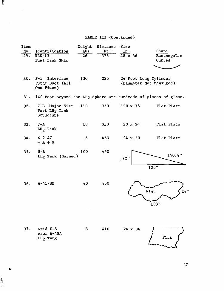
TABLE I11 (Continued)
I t e m Weight Distance Size No. I d e n t i f i c a t i o n Lbs . F t . I n . Shape 29. RRS-13 26 375 48 x 36 Rectangular
Fuel Tank Skin Curved
- W
30. F-1 Interface 150 225 24 Foot Long Cylinder Purge Duct ( A l l - (Diameter Not Measured) One Piece)
31. 100 Feet beyond the LH2 Sphere are hundreds of pieces of g l a s s .
32. 7-B Major S i z e 110 350 120 x 78 F l a t P l a t e P a r t LH2 Tank S t r u c t u r e
33. 7-A LH2 Tank
34. 6-2-47 + A + 9
10 350
8 450
35. 8-B 100 450 LH2 Tank (Burned)
36. 6-41-8B 40 450
37. Grid 0-8 Area 6-488 LH2, Tank
8 41 0
30 x 24 F l a t P l a t e
24 x 30 F l a t P l a t e
*.72" 140.4"
24 x 36 I-J 27

Item - No. I d e n t i f i c a t i o n 3 8 . 7 - D 6-31
3 9 . Grid 8-G Area 6 Part 22 4" buried i n Gromd on Edge
4 0 . 7-H Area 6 , Part 20
41. 6-2-21 Lnters tage Sk ir t + F + 5
4 2 . 10-A 363 LH7 Tank
TABLE I11 (Continued)
Weight Di s tance S i z e Lbs . Ft. In. - Shape
7 500 28
7 550
26 550
FwdL. Dome Structure
L ] 19"
30 Est 1100 18 If
28
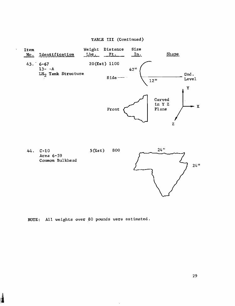
TABLE 111 (Continued)
. Item Weight Distance Size - No. Identification . . . . . , Lbs . Ft. - In. Shape
43. - 6-67 13- -A La2 Tank Structure
44. c-10 Area 6-59 C ommon Bul khe ad
20 ( E s t ) 1100 42" r
Gnd . Side" - __ Level
I Y
Front
Curved
P1 ane
Z
5(Est) 800 24
24"
NOTE: All weights over 80 pounds were estimated.
29

TABLE I V
CALCULATION OF INITIAL VELOCITIES FOR SELECTED FRAGMENTS
~ . ~~
. ~~~ - ." ~ ~~ ~
IterJ: Weight Assumed Area CD A Distance, Min. Vel.
No. l b s . ~. .~ ~ GP @L" W F e e t ~~ ~~- Fee t /Sec . ""
- - ~ ~~ .~ ~ ~. . . . ..
"
1 54 .77 1.48 .021 400 130 2 14 .79 .48 .027 400 137 3 19 .78 2.16 .089 35 0 180 4 9 .79 2.36 .207 300 45 0
10 25 .88 1.94 .068 175 95 14 1 2 .79 1.11 .073 180 95 25 87.5 .79 21.6 .195 300 -351) 5 30 26 4 1.6 .26 . lo4 300 165 27 4 1.6 .26 . l o4 300 165
39 7 .79 2.5 .282 550 > 4000 40 26 .79 7.37 . 2 24 550 3000
1900 ' 41 28 .79 10.9 .308 350
9~ Item numbers r e f e r t o T a b l e 111. JcJc Assumption of 45" f l i g h t a n g l e g i v e s v e l o c i t i e s e q u a l t o o r less
than actual. I
30

TABLE V
SUMMARY OF LOX/LH2 EXPERIENCE WITH FULL-SCALE FLIGHT WEIGHT TANKAGE''c
F l i g h t and Tanking S t a t i c F i r i n g s Operations
S -Iv
Centaur
5 6
28 10
fc Numbers are estimates based on r e s u l t s of informal inqu i r i e s t o Gene ra l Dynamics, L e w i s Research Laboratory, and Marshall Space Flight Center personnel .
31

FIGURE: 1. MOVEMENT OF VEHICLE AFTER EXPLOSION
32

FIGURE 2. VIEW OF TEST STAND AFTER EXPLOSION
33

+I5 I I I l l
I
t14 -
+13 -
+12
+11 -
+10 -
622
620 623
-7 t 6-8OA
- 8
-9
-10
-1 1
-12
-1 3
-14
-1 <
269
667
663
i22 73
T
-2 247
635 237 654 631 63 0
636 651
8 32 VDA-4 GSEd VDA-7 VDA-6 VDA-5
n
SG 200 E
7
6-1 6-2
) SCALE- r SQUARE
I 1
I 7
FIGURE 3 . FRAGMENT DISPERSION PATTERN
34

FIGURE 4 . GLASS BREAKAGE PATTERN
W m
FIGURE 5. DAMAGE TO BUTLER BUILDING, TS-1
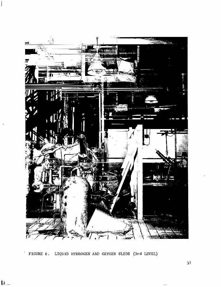
. FIGURF, 6 . L I Q U I D HYDROGEN AND OXYGEN SLEDS (3rd LEVEL)
37

FIGURE 7 . VEHICLE DEBRIS ON TOP OF ENGINES (4th LEVEL)
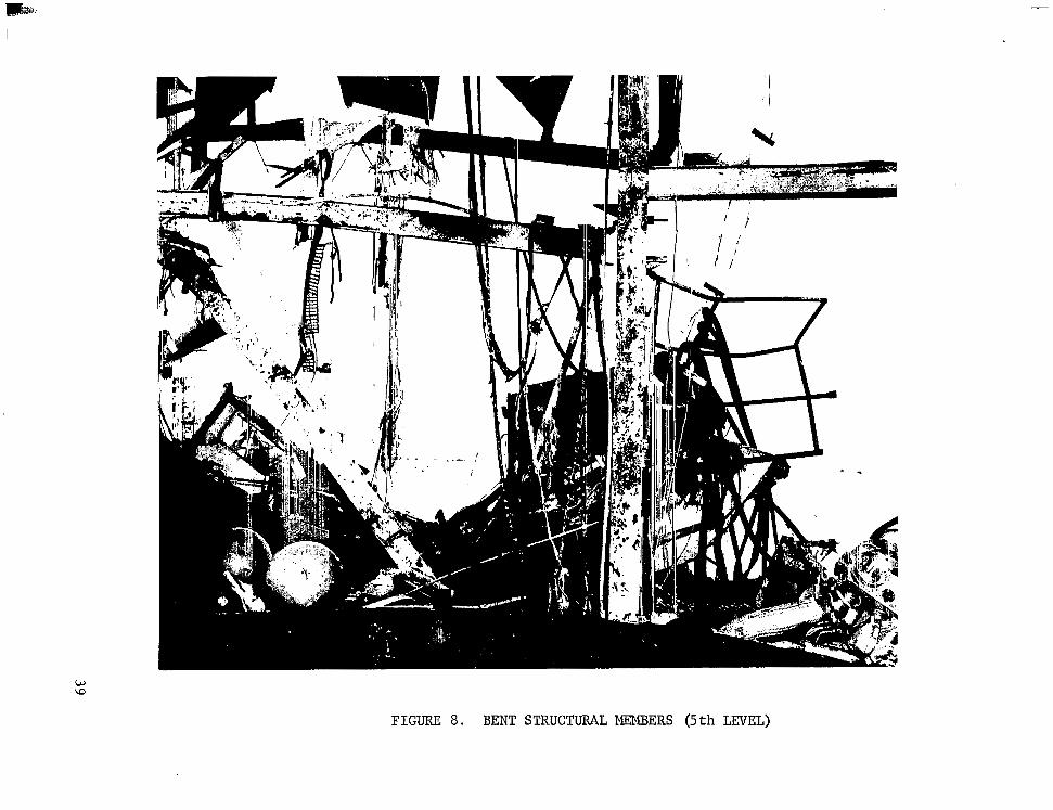
FIGURE 8. BENT STRUCTURAL MEMBERS (5 t h LEVEL)

c 0
FIGURE 9. CABLE RACEWAY AND ELEVATOR SHED (6th AND 7th LEVEL)
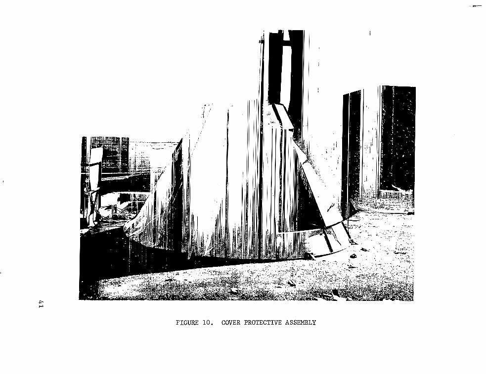
FIGURE 10. COVER PROTECTIVE ASSEMBLY
.
FIGURE 11. DAMAGED 1-B-EA.M
42

IO.000
I.000
100
IO I I I I I
0 5 0 IO0 I50 200 250 300 3 50 VELOCITY, FEET/SEC
FIGURE 12. R E U T I O N BETWEEN I N I T I A L V E L O C I T Y AND GROUND RANGE (LOW VELOCITY RANGE)
43

I 1111llIIIllllIllIlIIIIIIIlIIII~111111111
l00,000
10,000
w I- w LL
w' a (3 z K
1,000
I oc
I
.03
0 200 500 I O 0 0 2000 3000 VELOCITY, FEETISEC
FIGURE 13. RELATION BETWEEN I N I T I A L V E L O C I T Y AND GROUND RANGE (HIGH VELOCITY RANGE)
44


10000
1000
100
10
1
F IGl
0
0
A LH2/LOX 0 RP-l/LH,/LOX A UDMH/N,H,/N204 0 LH2 IN AIR
I I I I I
10’ 102 10 3 104 105 1 0 6
TOTAL PROPELLANT WEIGHT, POUNDS
E 15. FIREBALL DIAMETERS FOR VARIOUS WEIGHTS AND TYPES OF PROPELLANTS
f
100 I I I I
10
10’ lo2 1 0 3 1 0 4 1 0 5 - 1 0 6
TOTAL PROPELLANT WEIGHT, POUNDS
FIGURE 1 6 . FIREBALL DURATION FOR VARIOUS WEIGHTS AND TYPES OF PROPELLANTS

REFERENCES
1. "Final Report , S-IV A l l Systems Stage Incident, January 24, 1964," A p r i l 10, 1964 . [C las s i f i ed ( conf iden t i a l ) i n t e rna l document]
2 . "S t ruc tura l Des ign for Dynamic Loads," C. H. Nor r i s , e t a l . , Mc-Gray-Hill, 1959.
3 . Pou l t e r , T . C . , "Transmission of Shock i n Homogeneous and Non- Homogeneous A i r and Poss ib l e Damage to Bu i ld ing .S t ruc tu res fo r Moderately S m a l l Explosive Charges," Stanford Research Inst i tute , September 9, 1955.
48 NASA -Langley, 1964 M3 1 7

"The aeronautical and space activities of the United States shall be conducted so as to contribute . . . to the expansion of human knowl- edge of phenomena in the atmosphere and space. The Adminirtration shall provide for the widest practicable and appropriate dissemination of information concerning its activities and the results thereof."
" N A T I O N A L AERONAUTICS AND SPACE ACT OF 1958
NASA SCIENTIFIC AND TECHNICAL PUBLICATIONS
TECHNICAL REPORTS: Scientific and technical information considered important, complete, and a lasting contribution to existing knowledge.
TECHNICAL NOTES: Information less broad in scope but nevertheless of importance as a contribution to existing knowledge.
TECHNICAL MEMORANDUMS: Information receiving limited distri- bution because of preliminary data, security classification, or other reasons.
CONTRACTOR REPORTS: Technical information generated in con- nection with a NASA contract or grant and released under NASA auspices.
TECHNICAL TRANSLATIONS: Information published in a foreign language considered to merit NASA distribution in English.
TECHNICAL REPRINTS: Information derived from NASA activities and initially published in the form of journal articles.
SPECIAL PUBLICATIONS: Information derived from or of value to NASA activities but not necessarily reporting the results .of individual NASA-programmed scientific efforts. Publications include conference proceedings, monographs, data compilations, handbooks, sourcebooks, and special bibliographies.
Details on the availability of these publications may be obtained from:
SCIENTIFIC AND TECHNICAL INFORMATION DIVISION
NATIONAL AERONAUTICS AND SPACE ADMINISTRATION
Washington, D.C. PO546
.. ." . ..... .. . .