technical memorandum 86-68260-13-03 aerial missions ... - usgs · u.s. geological survey national...
TRANSCRIPT

U.S. Department of the Interior Bureau of Reclamation September 2013
Technical Memorandum 86-68260-13-03
Aerial Missions with Small Unmanned Aircraft Systems to Monitor Sediment Flow and Changing Topography Resulting from the Removal of Dams on the Elwha River Elwha River Restoration, Washington Pacific Northwest Region


Mission Statements
The mission of the Department of the Interior is to protect and
provide access to our Nation’s natural and cultural heritage and
honor our trust responsibilities to Indian Tribes and our
commitments to island communities.
The mission of the Bureau of Reclamation is to manage, develop,
and protect water and related resources in an environmentally and
economically sound manner in the interest of the American public.

U.S. GEOLOGICAL SURVEY National Unmanned Aircraft Systems (UAS) Project Office BUREAU OF RECLAMATION Technical Service Center, Denver, Colorado Emergency Management and GIS Group, 86068260
Technical Memorandum No. 86-68260-13-03
Aerial Missions with Small Unmanned Aircraft Systems to Monitor Sediment Flow and Changing Topography Resulting from the Removal of Dams on the Elwha River
Elwha Dam Olympic National Park (Washington) Douglas Clark, Ph.D. 6 November 2013__________ Preparer Date Physical Scientist, USBR, Emergency Management and GIS Group, 86-68260
Alan Bell 6 November 2013 Preparer Date Physical Scientist, USBR, Emergency Management and GIS Group, 86-68260
Jeff Sloan 6 November 2013 Preparer: (type in name) Date Cartographer, USGS, National UAS Project Office, MS-980
Mark Bauer 6 November 2013 Preparer: (type in name) Date Geospatial Analyst, Parallel Inc. USGS National UAS Project Office, MS-980
Susan Goplen 6 November 2013 Preparer: (type in name) Date IT Specialist, USGS, National UAS Project Office, MS-980

Elwha UAS Study
iii
Bruce K. Quirk, Ph. D. 29 October 2013 Peer Reviewer (type in name) Date UAS Liaison, USGS, Advanced Systems Center, MS-562 Title, Agency, Group, Mail code Section Reviewed: All
Michael E. Hutt 29 October 2013 Peer Reviewer (type in name) Date Cartographer, USGS, UAS National Project Office, MS-980 Title, Agency, Group, Mail code Section Reviewed: All
Lance Brady 29 October 2013 Peer Reviewer Date UAS Operator Fire Management Specialist, BLM, National Operations Center Title, Agency, Group, Mail code Section Reviewed: All
Jerry Freilich, Ph.D. 3-Sept-2013 Peer Reviewer Date Research Coordinator, NPS, Olympic National Park, 600 East Park Avenue Port Angeles, WA 98362 Section Reviewed: National Park Service (NPS) Permitting Process

Contents
Page
Table of Contents Background ........................................................................................................... 1 Project Objectives ................................................................................................. 1
Methods and Equipment National Park Service (NPS) Permitting Process. ... 2
The FAA Certificate of Authorization Process ................................................. 5 The Department of the Interior Office of Aviation Services - UAS Operational
Procedures Memorandum (OPM) No. 13-11.................................................... 6 Unmanned Aircraft System Platform................................................................ 6
Aircraft Onboard Sensors ................................................................................. 7 Flight Planning .................................................................................................. 8
Flight Missions................................................................................................ 12 Field Operations .............................................................................................. 12 Data Processing to Produce Orthorectified Photography and Digital Elevation
Models............................................................................................................. 13 Data Processing Assessment ........................................................................... 15
Interior Orientation ................................................................................... 15 Absolute Orientation ................................................................................. 16
Data Accuracy ................................................................................................. 17 Testing the Accuracy of the Acquired Data and the Derived Products .... 17
Digital Orthophoto .................................................................................... 18 Digital Elevation Model ............................................................................ 20
Results .................................................................................................................. 21 UAS vs. Conventional Aerial Photography vs. Satellite Imagery .................. 22 Conventional Commercial Aerial Photography .............................................. 22
Satellite Imagery ....................................................................................... 23
Bibliography ........................................................................................................ 25 Appendix A. .............................................................. Error! Bookmark not defined.
Appendix B. Raven RQ-11A Camera Specifications ......................................... 33

Elwha UAS Study
1
Background
The Elwha River Restoration Project involves the largest dam removal project in
U.S. history. The restoration effort, coordinated by the Department of the Interior
(DOI), includes federal, state, local, and tribal support. Dam removal will allow
for renewed salmon, trout, and char spawning, and ecosystem restoration
throughout Olympic National Park. Removing the Elwha and Glines Canyon
Dams will expose over 20 million cubic meters of sediment that is presently
trapped in the reservoirs behind both dams.
Erosion and transport of this sediment by the river will cause major geomorphic
changes not only to the reservoir deltas, but also to the downstream river and
shoreline. Tracking the erosion of the reservoir deltas and downstream sediment
movement is a high priority for managers and scientists who will monitor the
Elwha River restoration. The research results of the Elwha work will contribute
significantly to other future dam-removal projects. Because this is the first dam
removal on such a large scale, there are presently uncertainties about how rapidly,
and in what patterns, sediment will erode from the reservoirs and move
downstream. A monitoring program has been established to track the sediment,
but funding limitations have not allowed for a complete overall picture of
sedimentation processes. The UAS flights were designed to support this
monitoring effort. A secondary purpose of this research was to test whether these
data gaps could be answered by using aerial over-flights, including those from
unmanned aircraft systems (UAS), to monitor changes in the reservoirs and river
channels.
The United States military made several AeroVironment Raven RQ-11A
unmanned systems available to DOI in 2008. The U.S. Geological Survey -
National UAS Project Office and the DOI Office of Aviation Services, which
oversees all aviation activities within DOI, are leading the effort to train DOI
employees in UAS safety and operational procedures to test the utility of UAS for
DOI image capture missions, and coordinate national airspace issues with the
Department of Transportation Federal Aviation Administration (FAA).
Project Objectives
The use of the DOI unmanned systems for monitoring the Elwha River changes
took place in two separate image acquisition flights in June and September of
2012. The cooperative effort with the Bureau of Reclamation (BOR), the
National Park Service (NPS) and the U.S. Geological Survey (USGS) combined
the skills of UAS operators, hydrologists, biologists, and geographic information

Elwha UAS Study
2
systems and remote sensing experts. The proof-of-concept missions set out to
discover the capabilities of the new technology for mapping topography. The
benefit of the project is far reaching in terms of the timeliness and type of data
acquired. The aerial imagery collection provides data for on-going studies, future
research, and development of an historical record. This project had the following
objectives:
Outline the permitting and authorization processes involved with flying
within the National Airspace System over the DOI, National Park Service
lands.
Outline and describe the process of UAS mission operations, data
acquisition and data processing.
Conduct a data and accuracy assessment of the derived orthoimagery
products and elevation models from the UAS acquired data over the
accessible portion of the former Lake Aldwell lake bed.
Conduct an overall assessment and feasibility of using low-altitude UAS
data collection capabilities for topographic mapping.
Provide readers with an overview of mission planning, mission operations,
and data processing
Make recommendations as to the utility of UAS to meet or extend the
Bureau of Reclamation remote sensing capabilities.
Methods and Equipment
National Park Service (NPS) Permitting Process DOI UAS flights that launch or land in a U.S. National Park must obtain a park permit
and pilots must contact the NPS Aviation Manager. (See:
http://inside.nps.gov/waso/contacts.cfm?lv=3&prg=359). If the UAS will fly over
a park, but not launch or land in the park, pilots should also contact the NPS
Aviation Manager and park management. Flights in National Parks are subject to
NPS policies, Office of Aviation Services policies, and to FAA regulations.
http://inside.nps.gov/waso/custommenu.cfm?lv=3&prg=359&id=11288)
http://oas.doi.gov/library/ib/library/FY2013/IB1305.pdf
http://www.faa.gov/about/initiatives/uas/reg/

Elwha UAS Study
3
To apply for a scientific or research permit to conduct UAS flights, applicants
should go to: http://science.nature.nps.gov/research (Figure 1). Click the button "Create
a new Permit Application." After the applicant fills in contact information and
indicates the park in which work will be conducted, a link will appear where
he/she can upload a project statement. The website also hosts a document that
presents the requirements for such permits with detailed information on the level
of detail needed in the research proposal. Generally speaking, very detailed
information about the formal project statements is only required for very large,
very complex, or very invasive projects. For small scale projects, a project
statement of 2-3 pages is usually sufficient. It should focus on essential project
Figure 1: National Park Service Research and Reporting System
elements, (e.g., how many samples, how many visits) rather than the theoretical
underpinnings of the work). Submitted proposals will be entered into the NPS
database and also to NPS administrators. After filling out the main form there is a
place to add additional parks to the application, so that the same application may
be used for any or all parks in the NPS system.
The following information is required to successfully complete the application
process.
Project title
Purpose of study
Study start and end dates

Elwha UAS Study
4
Identification of any federal funding agencies
Location of activity in the park
Method of access
Names of co-applicants
If researchers will be collecting specimens, contact information of
repositories
A copy of the study proposal
A copy of all peer reviews
Study title
Study purpose
Summary of methods
Activity type:
o Research
o Education
o Inventory
o Monitoring
o Other
Funding source
Name of the park
Location within the park where work will occur
Field research start and end dates
Study start and end dates
List of Co-Investigators
Location of maps, data, and photography after the research is finished
Each application the NPS receives is peer reviewed. To speed the application
process it is advisable to contact an NPS staff member in the project subject area
(aviation, biology, geology, etc.) for advice. Average review and processing time
is typically three to four weeks, so it is a good idea to start the process as early as
possible.
Occasionally, if the proposed UAS work is deemed to be out of the ordinary (eg.
significantly different from the routine work conducted in the park) or if the work
is to be conducted in a designated Wilderness Area, a Minimum Requirements
Analysis Worksheet may be required. In such cases, management actions,
including research efforts, must comply with the minimum requirements mandate
set forth in the Wilderness Act, Section 4(c). The purpose of the minimum
requirements concept is to reduce the effects of an action on the wilderness
character and values. The minimum requirements process involves a
determination of whether a proposed research or management action is
appropriate and necessary for the administration of the area as wilderness and
does not pose a significant impact to its wilderness resources or character.
Worksheets can be obtained at: http://www.nps.gov/ever/upload/EVERMinimumToolInstruct.pdf .

Elwha UAS Study
5
The FAA Certificate of Authorization Process The Certificate of Authorization (COA) is an approval issued by the FAA - Air
Traffic Organization to a public operator requesting permission to fly a specific
UAS activity over a specific area for a defined period of time. UAS missions are
reviewed on a case-by-case basis. After a complete application is submitted, the
FAA conducts a comprehensive operational and technical review. If necessary,
provisions or limitations may be imposed as part of the approval to ensure the
UAS can operate safely with other airspace users.
The COA includes, but is not limited to, the operational plan, risk management,
airworthiness, airspace, pilot qualifications, radio frequency and communication
plan, and should be developed and submitted using the COA online system found
at the following internet address: https://ioeaaa.faa.gov/.
From a period beginning in 2009 to the present time of this publication (2013),
the FAA has required several documented approvals. Included in the request for
flight authorization are the following:
Project description
Project flight operations
Class of airspace to be flown
Date of operation
Radio frequency spectrum analysis approval
Notice to Airmen (NOTAM)
Flight operations plan including maps and authorized area extents
Special circumstances (special use permits)
UAS system descriptions
Performance characteristics (launch/recovery)
Airworthiness
Operating procedures (emergency, lost link, lost communications)
Flight aircrew qualifications (medicals, training, currency and proficiency)
Once the request has been drafted by the requesting agency, it is then internally
reviewed by the agency’s Bureau Aviation Manager and the Office of Aviation
Services UAS Coordinator. The request is then sent to the FAA and the approval
or denial process begins. The current 2012-2013 procedural timeline set in place
by the FAA is based on three review phases; the commit phase, the validation
phase, and the activation or release phase.
The commit phase involves the FAA administrative review. The validation phase
begins a 60 business day detailed review. The determination of the review results
in the release of the COA for additional edits by the submitting agency, or the
activation for operational use of the UAS by the requesting agency per the
parameters in the request. The COA can be renewed or extended on a case-by-
case basis, or allowed to expire if no additional flight missions are required.

Elwha UAS Study
6
The Department of the Interior Office of Aviation Services - UAS Operational Procedures Memorandum (OPM) No. 13-11. The Department of the Interior Office of Aviation Services outlined a
memorandum in 2009 that initiated the operational procedures for use of UAS
within the agencies. The memorandum and subsequent updates, further define the
agency authority, policies, procedural guidelines, pilot qualifications and
limitations beyond what is described by the FAA requirements and specific
mission COA (Appendix A). Included with these guidelines are:
Approval of the Bureau Aviation Office
Possession of a valid and current COA from the FAA
Exercise operating limitation within the defined geographical boundary,
COA and OPM provisions
Meet the Department of the Interior UAS Pilot/Mission Operator/Observer
training and certification
Operator letter of authorization specifying the UAS vehicle that is
approved to be used
Visual Flight Rules are used regardless of the UAS operational airspace
Unmanned Aircraft System Platform
The RQ-11A Raven (Figure 2) is a hand-launched, battery operated, unmanned
aerial vehicle. The vehicle is 36 inches in length and has a 55 inch wingspan.
The typical operating altitude is 100 – 400 feet above ground level (AGL) with an
average speed of about 20-30 mph, a flight range of approximately 10 km, and a
flight duration length of about one hour. Two persons are required for flight
operations of the Raven; one for piloting the aircraft and another to serve as the
mission operator on the navigational laptop computer. In addition, one or more
trained observers must maintain visual line of sight of the aircraft at all times,
based upon current FAA UAS operation regulations.
Figure 2 AeroVironment Raven
RQ-11A

Elwha UAS Study
7
Aircraft Onboard Sensors The Raven UAS carries a payload of either an electro-optical video camera with a
forward and side-looking view or an infrared thermal video camera with only a
forward view or a side view. Including the Raven UAS nose cone, each camera
weighs approximately 6.5 oz. The Department of the Interior agencies are also
testing the use of higher resolution cameras such as the GoPro Hero2. With the
permission of OAS, the new camera can be retrofitted onto the system in order to
take advantage of more recent developments in camera and sensor technologies
(Figures 3).
The current retrofit procedures for
utilizing the new cameras involve
removing one of the existing (side-
looking) video cameras in the nose cone.
A new hole is drilled in the bottom of the
nose cone for the camera enabling it to be
pointed straight down (nadir) to better
collect vertical images required for
mapping purposes. The camera is
surrounded by packing material or other
means of firmly securing it into position.
The nose cone is then ready for use again in flights just as it was originally used
(Figures 4 and 5). The images are stored on-board a micro secure digital (SD)
card with the camera setting on video or still frame capture at an approximate one
to three second timed interval. The imagery is copied from the SD card upon
landing to a computer hard drive to complete the data collection.
These sensors should weigh the same as the existing cameras to minimally affect
existing UAS flight characteristics. Specifications of the existing cameras and the
GoPro Hero2 retrofitted cameras can be found in Appendix B.
Figure 4. GoPro Hero2 integrated into the Raven nose cone.
Figure 1. GoPro Hero2 with 5.4 mm and 2.5
mm lenses.

Elwha UAS Study
8
Figure 5. GoPro Hero2 in the nose cone reattached and used as it was
originally designed.
Flight Planning Aerial photography flight planning is a way of predetermining the most efficient
method of flying over a geographic area of interest to collect a series of
overlapping images that can be used for scientific mapping, surveying or
monitoring. Photogrammetry is the scientific method of using the aerial images
for accurate measurements and creation of three dimensional models. Flight
planning utilizes a variety of mathematical computations, such as flight height,
cameral focal length, and camera sensor sizes to achieve the best results for
proper image collection to later develop elevation models and rectified images.
The traditional flight height, grid patterns and overlap requirements used by aerial
photography companies can also be implemented by a UAS airframe and are
desirable for achieving the best results in the post-processing of the data in
photogrammetric software. Flight height planning and direction of flight must be determined in advance as well as, the method of flight that will be used, such as
autonomous or manual modes of controlling the aircraft in a grid or linear pattern.
A minimum of a 60% forward and 30% side overlap between flight paths are
desired in order to collect sufficient stereo image overlap required to derive a
three dimensional model and obtain full coverage of the area. Camera collection
trigger time such as one to three seconds between exposures on average is
optimal for overlapping photo coverage but, this can vary due to flight height,
ground speed and wind conditions. The faster photo interval will greatly increase

Elwha UAS Study
9
or decrease the amount of overlapping data and the amount of data volume
collected.
A standard formula for calculating the sensor pixel size, ground sample distance
and photo footprint on the ground can be useful for flight planning as described
by a commercial vender providing UAS data processing services (DroneMapper
2013. See: http://dronemapper.com/):
GSD = PS * FH / FL
Where:
GSD = Ground Sample Distance
PS = Pixel Size (Sensor Size / Image Width or Height)
FH = Flight Height (Above Ground Level (AGL))
FL = Focal Length
Once the camera information is known, flight path, camera exposure timing,
altitude and overlapping transect patterns can be determined. For the Elwha River
Restoration Project utilizing the GoPro Hero2 camera, the flight plan parameters
were as follows:
Example of GoPro Hero2 Parameters:
Image Width = 3840 pixels
Image Height = 2880 pixels
Megapixels = 11 mp
Sensor Size (width) = 6.20 mm
Sensor Size (height) = 4.60 mm
Pixel Size (width) = .0016 mm/pixel
Pixel Size (height) = .0016 mm/pixel
Flight Height (AGL) = 400 feet (122 meters)
Focal Length = 4 mm
GSD = .0016 mm * 122 m / 4 mm = 4.88 cm
With the parameters calculated, additional information can then be used in the
flight planning of the mission. This would include best estimate for flight heights,
direction, transect spacing for overlap and flight pattern (Figure 6).

Elwha UAS Study
10
Figure 6. Flight planning calculations for the GoPro Hero2 at 100 ft. intevals above ground level
(AGL).
Photo Footprint on the Ground:
(width) 3840 pixels * 4.88 cm = 187.3 m (614.5 ft)
(height) 2880 pixels * 4.88 cm = 140.5 m (460.9 ft)
Figure 7. Still frame capture from the GoPro Hero2 with calculated ground dimensions at a flight
altitude of 400 feet (AGL).
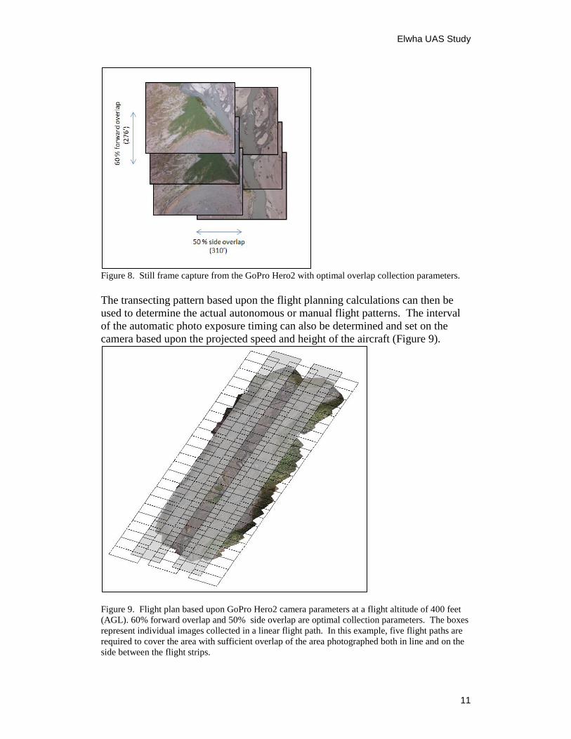
In-track flying requires an image to be captured at a spacing that would
accomplish a minimum of a 50% sidelap and 60% overlap relative to the ground
(Figure 8):
(Image height) 615 feet * 50% = 310 feet on the ground
(Image width) 460 feet * 60% = 276 feet on the ground
Elwha UAS Study
11
Figure 8. Still frame capture from the GoPro Hero2 with optimal overlap collection parameters.
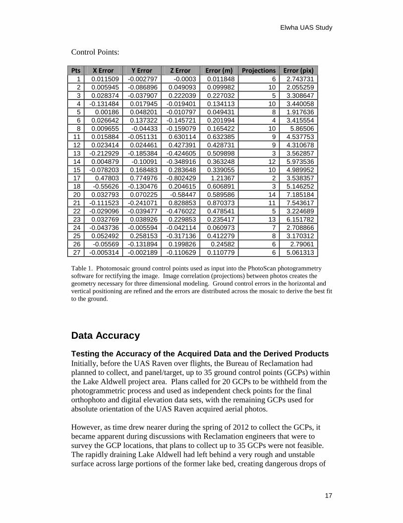
The transecting pattern based upon the flight planning calculations can then be
used to determine the actual autonomous or manual flight patterns. The interval
of the automatic photo exposure timing can also be determined and set on the
camera based upon the projected speed and height of the aircraft (Figure 9).
Figure 9. Flight plan based upon GoPro Hero2 camera parameters at a flight altitude of 400 feet
(AGL). 60% forward overlap and 50% side overlap are optimal collection parameters. The boxes
represent individual images collected in a linear flight path. In this example, five flight paths are
required to cover the area with sufficient overlap of the area photographed both in line and on the
side between the flight strips.

Elwha UAS Study
12
Flight Missions The planning of UAS missions can follow traditional flight collection methods,
however many missions must be altered to some degree in the field due to
exaggerated effects of wind speed and direction on the small aircraft and
constraints within the terrain being flown. Flexibility with flight missions is
necessary to ensure safety and success in interpreting all external factors involved
in operating lower altitude flights, the lighter weight of the aircraft, and the lack
of stability with the smaller UAS airframes. For example, if a flight mission plan
is initially designed to fly north and south in a ‘lawn mowing’ pattern, but the
wind is from the northeast at 15 mph, the fight plan would need to be changed to
collect photo strips into the wind for stability and slower flight speeds in order to
collect the most stable and clear images (Figure 10).
Figure 10. Flight plan transects can be altered to aid in collecting a consistent pattern of data.
Instability of the lighter weight aircraft and effects of wind conditions may require one-directional
collection versus a more efficient bi-directional acquisition.
Field Operations Once all logistics planning is in place, actual field operations can commence with
minimal set up and time required for the actual UAS flights and imagery
acquisition (Figure 11). Video imagery is captured via an analog downlink from
the aircraft to the ground station. In addition, higher resolution still frame images
are captured on-board through a data storage card within the GoPro Hero2
camera.

Elwha UAS Study
13
Figure 11. Field operations require minimal set up for ground station navigation (laptop and
uplink/downlink antennas) with hand- launch and deep stall landing recovery of the small Raven
UAS.
Data Processing to Produce Orthorectified Photography and Digital Elevation Models Refined geometric correction for ultimate use in geospatial applications with
geographic information systems or other types of decision management systems
can be accomplished using various types of commercial data processing software
packages. One approach used in some of these packages provides for the
photogrammetric three-dimensional reconstruction of cultural objects and land
models utilizing imagery captured from hand-held or metric cameras and sensors.
This methodology is based upon computer vision technology and can work well
with low altitude imagery captured from a small UAS. Computer vision is based
upon artificial intelligence and image processing utilizing images from the real
world. It is most commonly applied in the field of robotics in which automated
processes and image analysis is interpreted or learned by processing millions of
mathematical computations to aid in visual perception and machine or robotic
learning. In the field of photogrammetry and remote sensing, this same idea can
be applied to aid in the derivation of three-dimensional modeling from real world
aerial imagery. These are the building blocks to highly accurate base geographic
data creation.
The UAS platform is best utilized for creating this type of data when imagery is
captured at near vertical angles; however, it is also possible for use with oblique
imagery for creating models. Fast moving advances in camera technology is
greatly aiding this method of data collection for deriving highly accurate models
from currently available off the shelf cameras that are integrated into the UAS.
The Agisoft PhotoScan software, developed in St. Petersburg, Russia is one
package that has shown great potential for processing the data captured from
small UAS. This software was utilized for the imagery captured over the Elwha
River Restoration Project (Figure 12). The general processing steps include:
Adding and aligning the overlapping images (preferably from different
heights and flight directions)

Elwha UAS Study
14
Adding any ground control point information Constructing a point cloud model based on intersecting vectors Building the geometry of the model Constructing an elevation model Draping the imagery to fit the model Exporting out the photogrammetrically rectified products
Step 1. Select, load and align all images to be used. Step 2. Generate a 3D point cloud.
Step 3. Build the geometry and elevation model. Step 4. Drape the imagery over the model.
Step 5. Export the elevation model. Step 6. Export the rectified orthophoto.
Figure 12. A systematic process of geometric correction and three dimensional reconstruction of
the river model over the Lake Aldwell area. Steps include selecting, loading and aligning the UAS
acquired images, point cloud creation with horizontal and vertical derivations, elevation modeling
and draping of the images, and export of the geographic products.

Elwha UAS Study
15
Data Processing Assessment The PhotoScan software generates graphic and tabular photogrammetric reports
(Figure 13) that can be used as a general assessment of the quality of the data
processing inputs and outputs. The report analyzes the various input parameters,
the data adjustment and variable used in constructing a model. The results reveal
the level of errors it is able to generate and provide an indication of the quality of
the final data products. Processing the September 24, 2012 Lake Aldwell area
UAS Raven aerial photos of the Elwha River Restoration Project included using
202 images collected by the GoPro Hero2 camera with a 4mm lens on board the
UAS.
Interior Orientation
No. of Images 202
Flying Altitude 169.329 m
Ground Resolution 0.0268237 m/pix
Coverage Area 0.928812 sq. km
Camera Stations 202
Tie Points 418301
Projections 1141317
Error 3.61681 pix Figure 13. Camera photo center locations (black dots) and number of correlated images (number
indicated by a color ramp) from the PhotoScan software. The values >9 would indicate a correlation of
at least 9 photos and usually many more shown in blue would show a strong tie between multiple
images. Those <3 shown in the yellow-red colors would represent a much weaker or less accurate
correlation between fewer photos.

Elwha UAS Study
16
Absolute Orientation
For image mosaic control input, 27 ground control points (GCPs) were captured
from existing orthorectified imagery collected from in an August 30, 2012 aerial
flight. The imagery was photogrammetrically corrected using surveyed field
ground control panels that were placed before imagery acquisition. In addition to
the panel control points, other image points that were identifiable on both the
existing orthoimage and on the UAS individual images were selected and used as
input into the PhotoScan photogrammetric model. Horizontal latitude and
longitude points were recorded along with vertical elevation measurements of the
same points using an October 16, 2012 LIDAR over flight (Figure 14).
Figure 14. Photo identifiable points are selected from an existing orthomosaic image with
elevation measurements from a LIDAR collection for input into the photogrammetric model.
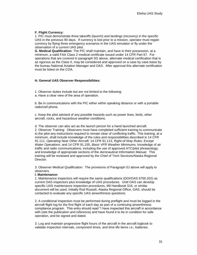
The geometric errors are adjusted after the refinements were made both manually
and automatically by the software to try to derive the best correction for the image
rectification and three dimensional model (Table 1).
Elwha UAS Study
17
Control Points:
Pts X Error Y Error Z Error Error (m) Projections Error (pix) 1 0.011509 -0.002797 -0.0003 0.011848 6 2.743731
2 0.005945 -0.086896 0.049093 0.099982 10 2.055259
3 0.028374 -0.037907 0.222039 0.227032 5 3.308647
4 -0.131484 0.017945 -0.019401 0.134113 10 3.440058
5 0.00186 0.048201 -0.010797 0.049431 8 1.917636
6 0.026642 0.137322 -0.145721 0.201994 4 3.415554
8 0.009655 -0.04433 -0.159079 0.165422 10 5.86506
11 0.015884 -0.051131 0.630114 0.632385 9 4.537753
12 0.023414 0.024461 0.427391 0.428731 9 4.310678
13 -0.212929 -0.185384 -0.424605 0.509898 3 3.562857
14 0.004879 -0.10091 -0.348916 0.363248 12 5.973536
15 -0.078203 0.168483 0.283648 0.339055 10 4.989952
17 0.47803 0.774976 -0.802429 1.21367 2 3.538357
18 -0.55626 -0.130476 0.204615 0.606891 3 5.146252
20 0.032793 0.070225 -0.58447 0.589586 14 7.185184
21 -0.111523 -0.241071 0.828853 0.870373 11 7.543617
22 -0.029096 -0.039477 -0.476022 0.478541 5 3.224689
23 0.032769 0.038926 0.229853 0.235417 13 6.151782
24 -0.043736 -0.005594 -0.042114 0.060973 7 2.708866
25 0.052492 0.258153 -0.317136 0.412279 8 3.170312
26 -0.05569 -0.131894 0.199826 0.24582 6 2.79061
27 -0.005314 -0.002189 -0.110629 0.110779 6 5.061313
Table 1. Photomosaic ground control points used as input into the PhotoScan photogrammetry
software for rectifying the image. Image correlation (projections) between photos creates the
geometry necessary for three dimensional modeling. Ground control errors in the horizontal and
vertical positioning are refined and the errors are distributed across the mosaic to derive the best fit
to the ground.
Data Accuracy
Testing the Accuracy of the Acquired Data and the Derived Products
Initially, before the UAS Raven over flights, the Bureau of Reclamation had
planned to collect, and panel/target, up to 35 ground control points (GCPs) within
the Lake Aldwell project area. Plans called for 20 GCPs to be withheld from the
photogrammetric process and used as independent check points for the final
orthophoto and digital elevation data sets, with the remaining GCPs used for
absolute orientation of the UAS Raven acquired aerial photos.
However, as time drew nearer during the spring of 2012 to collect the GCPs, it
became apparent during discussions with Reclamation engineers that were to
survey the GCP locations, that plans to collect up to 35 GCPs were not feasible.
The rapidly draining Lake Aldwell had left behind a very rough and unstable
surface across large portions of the former lake bed, creating dangerous drops of

Elwha UAS Study
18
six feet or more, particularly in the vicinity of the very active and shifting river
channels. In effect, these hazardous conditions restricted access to a much
smaller area of the former lake bed for both the survey and ground control panel
crews. During late May 2012, the survey crews could safely reach and survey
only 14 of the planned GCP locations to pin their locations. Prior to the first UAS
Raven overflight in June 2012, ground panel crews could safely reach, recover or
panel only seven of the planned GCP locations for Lake Aldwell. In effect, these
hazardous on-site conditions had derailed Reclamation plans to acquire an
independent source of higher accuracy data to be used for checking the UAS
Raven derived data sets.
By the time the joint DOI UAS Raven crew arrived for the first flight mission in
June 2012, lake bed conditions in the north/lower end of former Lake Aldwell
(nearer the Dam site) were determined to be unsuitable and unsafe for both the
ground crew and UAS Raven operations. For safety reasons, an on-site decision
was made to restrict the UAS Raven flights to only the southern/upper portion of
the former Lake Aldwell lake bed. Only three of the paneled GCPs ended up
being within the UAS Raven flight mission area and were visible in the
September 2012 UAS Raven aerial photos taken with the higher resolution GoPro
Hero2 camera. These three GCPs were used for control/absolute orientation
purposes, not as independent check points of higher accuracy.
In retrospect, ideally at least 20 stable-ground GCPs should have been collected
and paneled a few days before the first UAS Raven flight missions in June 2012,
then withheld from the photogrammetric process to serve as an independent check
source of higher accuracy for UAS Raven derived data. Then, the x-y-z positions
of the 20 GCPs would remain stable and unchanged between June and September
2012, and re-paneled for use as check points for the second UAS Raven mission
in September 2012. However, because of unstable and unsafe onsite conditions
and budget considerations, we did not have an independent source of higher
accuracy data, acquired near or at the time of UAS Raven aerial photo collection
that we could use to independently check the accuracy of the UAS Raven data.
Digital Orthophoto Accuracy assessments can be conducted in a number of ways. To ensure that end
products from the cameras on board the UAS can reliably meet required
resolution and positional accuracy, a standard validation process can be employed
to check horizontal and vertical values against surveyed ground control or an
accepted base image from previous corrected data collection. The 1999 National
Standard for Spatial Data Accuracy (NSSDA) provides a good framework for
assessing the horizontal accuracy of an orthorectified image from a small UAS
and for the creation of a positional accuracy statement (Figure 15).

Elwha UAS Study
19
Figure 15. Test points selected on both the orthomosaic base image collected August 30, 2012
and from the UAS Raven photogrammetrically derived orthophoto from September 24, 2012.
Coordinates are collected with the measured differences calculated to derive a statistical average
of the ground position error between the base image and newly derived UAS image mosaic.
Horizontal Accuracy Statistic Worksheet
Positional Accuracy Statement:
Tested 4.365 meters horizontal accuracy at 95% confidence level
Table 2. Twelve test points are selected on both the aerial photography orthophoto base and the
UAS Raven GoPro Hero2 photogrammetrically derived orthophoto. An accuracy assessment is
calculated following the National Standard for Spatial Data Accuracy method of measurement and
accuracy reporting. Note: The base orthophoto had a ground sample distance of 3.96 inches
(10.05cm) and the UAS orthophoto had a ground sample distance of 2.04 inches (5.18cm). Error
in the measurement could be introduced in using the lower resolution base orthophoto in the
statistical input. However, this was the highest resolution image available at this time and with
lack of ground control, the only option for a similar comparison.

Elwha UAS Study
20
Digital Elevation Model
For elevation accuracy assessments, a direct comparison can be made against the
vertical elevations of the derived UAS elevation model from imagery collected on
Sept. 24, 2012 and a LIDAR base elevation model from an over flight collected
on October 16, 2012 - approximately 22 days later. Random points are selected in
a distributed pattern and elevation measurements are collected for each data set
over the exact same points. The vertical measurements are compared with an
overall difference averaged and root mean square error analysis applied to derive
the vertical accuracy statement (Figure 16).
The specifications for the October 16, 2012 LIDAR data acquisition include a
survey altitude of 900-meters above ground level, pulse rate of 106 kHz, 21 cm
laser width at ground level, 26-degree field of view, an average of 8 pulses per
square meter initial data collection, and a tested vertical accuracy over open
terrain (bare earth) of approximately 15 cm. Twelve test points are selected on
both the LIDAR base elevation model and the UAS Raven GoPro Hero2 elevation
model and a vertical accuracy assessment is calculated following the National
Standard for Spatial Data Accuracy method of measurement and accuracy
reporting. Note: The LIDAR was the best available source to use and compare
against the UAS photogrammetrically derived model. Error in the measurements
could be introduced with the larger sampling area of the LIDAR in contrast to the
much higher resolution of the data collected from the UAS (Table 3).
Figure 16. Random points are selected with latitude, longitude and elevation values recorded form
both the October 2012 LIDAR collection (left) and from the UAS Raven GoPro Hero2
photogrammetrically derived elevation model (right). These values are then used in a statistical
analysis to derive an average of the error difference between the two data sets in order to be able
to produce a positional accuracy statement.

Elwha UAS Study
21
Vertical Accuracy Statistic Worksheet
Positional Accuracy Statement:
Tested 5.230 meters vertical accuracy at 95% confidence level
Table 3. Twelve test points elevation values are recorded from both the LIDAR base elevation
model and the UAS Raven GoPro Hero2 elevation model. The difference between the two
datasets and a statistical average is calculated in order to produce a standard vertical accuracy
statement.
Results
Although an image orthomosaic and elevation model was derived from the initial
June 2012 UAS Raven flight missions, the results were not satisfactory. The
imagery using the standard UAS Raven camera was lacking in adequate fidelity
and resolution. As a result, the confidence level in the derived elevation data was
not high. An immediate search was done for better camera options for the UAS
Raven and due to payload weight limits, a limited selection of camera choices
were available. The best option at the time was a GoPro Hero2 which delivered
much higher resolution and clarity. This camera was then used for the subsequent
September 2012 UAS Raven flight mission.
As described in this paper, significant progress was made by using the GoPro
Hero2 camera for the September 2012 aerial photography mission. A useable
orthophoto and digital elevation model were derived from the GoPro acquired
aerial photos. However, the horizontal and vertical accuracy errors were higher
than anticipated. These higher accuracy errors are likely due to several factors;
1) The mix of GCPs used were not of sufficient horizontal and vertical accuracy
to support the UAS derived higher resolution orthophoto and digital elevation
data products - with the exception of the three GPS GCPs, the 27 other GCPs

Elwha UAS Study
22
likely contributed in degrading the UAS product accuracy.
2) The GoPro Hero2 camera/optics was not of sufficient quality to ensure an
adequate mapping level camera calibration and photogrammetric input.
3) The steep canyon and surrounding tall trees in the Lake Aldwell project area
did not allow for adequate perpendicular cross-flights over the project area. The
additional flight passes likely would have strengthened the camera calibration and
photogrammetric processing results.
Because of a lack of confidence in the initial June 2012 UAS Raven mission data,
and a change in the camera configuration for the following mission, a valid
comparison for sediment movement analysis between the June 2012 and
September 2012 UAS Raven missions was not possible.
UAS vs. Conventional Aerial Photography vs. Satellite Imagery Conventional Commercial Aerial Photography In general, the FAA restricts commercial fixed wing aircraft to a minimum
operational flight altitude of 1000 feet above the ground. In practice, and
depending on the project terrain, most commercial aerial photography mapping
contractors will not collect aerial imagery at a flight altitude of lower than 1200-
1500 feet above the ground. To meet higher resolution and larger scale elevation
data requirements, a commercial contractor will likely conduct large format
calibrated mapping camera acquired aerial photography flight missions, using a
fixed wing aircraft in the range of 1200-2000 feet above ground level.
However, a helicopter can operate and acquire aerial photography and LIDAR at
a much lower elevation, perhaps as low as 300-400 feet above ground level
depending on project area terrain. There are medium format, photogrammetric
quality digital cameras, professional grade digital SLR cameras and LIDAR
systems that can be mounted in helicopters to acquire engineering level quality
mapping data. For smaller project areas, this equipment along with advances in
associated airborne GPS/IMU may offer better pricing when compared to fixed
wing aircraft mission costs.
In either case, commercial fixed wing aircraft or helicopter based aerial photo
collection, the anticipated cost range for a one square mile project area, high
resolution accurate ortho-image and elevation data, including ground control
collection, would likely be $15,000-$20,000 price range for acquisition.

Elwha UAS Study
23
Satellite Imagery
Currently, with the highest resolution commercial satellite imagery capable of
capturing an image with a 46 cm ground sample distance, it would still not be able
to meet a two foot or better elevation contour interval or a one foot or better pixel
accuracy requirement for derived imagery products. A lower resolution three
meter elevation model and an approximate 20 inch ground sample distance
orthoimage requirement could be met using commercial satellite imagery with
sufficient collected ground control. Cost would be in the $10,000 range for
coverage over a 1-square mile project area.
Recommendations The UAS Ravens were built for military operations, primarily for reconnaissance
and surveillance. The standard equipped electro-optical video camera and
thermal infrared sensors are not designed or suited for higher resolution
photogrammetric mapping applications. The Ravens are limited in their payload
sensor capacity, limiting DOI options for significant improvement in higher
resolution cameras, optics, sensors, or IMU/GPS components. The UAS Raven
and its standard camera package could be useful to Reclamation for certain
surveillance and monitoring activities, and they are useful as an introductory
learning tool for operating a UAS. In the event access to a Reclamation facility
or associated infrastructure was blocked or prohibited due to a natural event
(landslide, earthquake, or other adverse natural/weather event), or dangerous on-
site conditions (fire, chemical, or radiation related event) a Raven or similar type
UAS could be put into operation to gather imagery remotely. However, the UAS
Raven is not recommended for use in Reclamation applications requiring more
precise measurements or mapping products.
The military surplus acquired UAS Ravens were built for the Defense Department
from 2002-2005. Most had experienced many hours of use from overseas
operation before coming to DOI, and have now exceeded their useful lifespan.
The UAS Ravens have not been produced since 2005, and spare parts are
becoming harder to attain. The UAS Raven cannot be cost-effectively modified
to make use of professional grade digital SLR cameras.
The UAS Raven flight management system can accommodate only a limited
number of waypoints for flight planning, resulting in a cumbersome flight plan
and operation that may result in gaps in area coverage or less desirable aerial
photo overlap. Modern commercial UAS systems can plan for hundreds of
waypoints, and account for wind speed and direction and adjust the flight plan
accordingly. This makes flight operations more efficient, effective, and results in
better stereo overlap coverage, and will allow the execution of better aligned

Elwha UAS Study
24
perpendicular cross-flights that will strengthen camera calibration results. The end
result being more effective and efficient photogrammetric processing, and
reducing the chances of having gaps in aerial photography coverage.
The GoPro Hero2 and other digital point-and-shoot type cameras are a vast
improvement in resolution and usefulness, when compared to the standard UAS
Raven cameras, particularly for mapping and measurement related applications.
However, the best results for mapping and measurement related applications will
be accomplished by a UAS utilizing higher resolution, professional grade (Nikon
or Canon 20 MP and above) digital SLR cameras such as the Nikon or Canon 20
megapixel models, which have better lenses and associated optical characteristics,
resulting in sharper images, better camera calibration results, more precise
measurements, and higher accuracy derived products.
The DOI now has another UAS available from military surplus - the vertical
takeoff and landing RQ-16 T-Hawk. It was first utilized in November 2012 and
was not available at the time of the Elwha River Restoration Project. It has since
been used several times by USGS for various projects, and does offer several
advantages over the UAS Raven platform, although it is not powerful enough to
incorporate a professional grade digital SLR camera as its primary sensor
package.
Significant cost savings, compared to a commercial aerial mapping company,
could be realized in using a UAS for imagery and elevation data acquisition and
production for smaller project areas such as a few square miles. Using in-house
UAS data acquisition and data processing capability, response time and data
delivery timeframes can be significantly shortened as compared to a commercial
acquisition. More modern UAS typically contain a smaller volume of related UAS
control and flight operations (ground control station) related equipment, resulting
in reduced travel and/or shipping related costs per mission. An aircraft number
limit imposed on the DOI Office of Aviation Services currently limits our ability
to acquire new UAS. The BOR, USGS, and Bureau of Land Management, have
investigated several fixed and rotary (helicopter type) UAS within the past 12
months. Several commercially available systems offer higher quality,
professional grade aircraft and camera systems, along with more efficient flight
planning (hundreds of waypoints) and flight management software than the Raven
UAS. In addition, several rotary type UAS have the ability to incorporate a
higher quality professional grade digital SLR camera as their imagery acquisition
sensor, in addition to having better flight planning/management software.
As we near the FAA 2015 deadline for guidelines for UAS operations in the
United States airspace, many commercial companies are expected to offer similar
higher quality UAS. We strongly recommend that for applications requiring more
precise measurements and higher resolution mapping related data that the Bureau
of Reclamation and DOI invest in both a rotary type UAS with the capability to
incorporate a professional grade digital SLR camera as its primary sensor package

Elwha UAS Study
25
and better flight planning/management software, and a fixed wing UAS that has
camera/optics and flight planning/management system better suited to true
photogrammetric applications.

Elwha UAS Study
26
Bibliography
Federal Geographic Data Committee, 1998. Geospatial Positioning Accuracy
Standards Part3: National Standard for Spatial Data Accuracy, FGDC-STD-
007.3-1998.
Minnesota Planning Land Management Information Center, 1999. Positional
Accuracy Handbook: Using the National Standard for Spatial Data Accuracy to
Measure and Report Geographic Data Quality.
Stoermer, Jon-Pierre. "DroneMapper Aerial Imagery Processing and
Photogrammetry." DroneMapper Customer Documentation | DroneMapper
Aerial Imagery Processing and Photogrammetry. Big Mountains Robotics, LLC,
02 June 2012. Web. 03 Sept. 2013. <http://dronemapper.com/documentation>.

Elwha UAS Study
27
Appendix A.
DOI OPERATIONAL PROCEDURES (OPM) MEMORANDUM NO. 13-11 Subject: DOI Use of Unmanned Aircraft Systems (UAS) Effective Date: January 1, 2013 Supersedes: OPM 11-11 issued on December 19, 2011 Expiration: December 31, 2013
1. PURPOSE. The purpose of this OPM is to provide guidance on the operations and management of Unmanned Aircraft Systems (UAS). 2. AUTHORITY. This policy is established by the Director, Department of the Interior, Office of Aviation Services(OAS) in accordance with the provisions of Departmental Manual 112 DM 12, 350 DM 1; and Secretarial Order 3250 dated September 30, 2003. 3. BACKGROUND. Current FAA policy is provided in Interim Operational Approval Guidance 08-01, Unmanned Aircraft Systems Operations in the U.S. National Airspace System (NAS). A. FAA retains the authority to approve UAS operations within the NAS in Class A, B, C, D, E and G airspace. B. When operating in Class A, B, C, D, E and G airspace, DOI UAS’s must be operated with a FAA Certificate of Waiver or Authorization (COA).
C. COAs are not required in Restricted, Prohibited, or Warning airspace. However, UAS operations in these specific airspaces will be regulated and approved by the Controlling Authority (a.k.a. “Range Control”). 4. POLICY. UAS by definition are considered aircraft. While their size, method of control, and airspace utilization procedures are different than manned aircraft, the overall responsibility for management within the Department of Interior (DOI) rests with the Office of Aviation Services (OAS). Ownership of all aircraft, including UAS, is a function and responsibility of OAS. Additionally, OAS will coordinate with other federal agencies on use and cooperate with the FAA on existing and proposed rule making. Department of Interior bureaus shall employ the following procedures when using any UAS, either DOI-owned or DOI contract vendor-owned and operated.

Elwha UAS Study
28
5. PROCEDURES AND GUIDELINES. A. UAS Project and COA Application:
1. The OAS Alaska Regional Director, Harry Kieling is the DOI UAS Coordinator for FAA COA applications, [email protected], 907-271-5626, 907-271-6569 (Fax).
2. The alternate UAS Coordinator is Alaska Region Aviation Safety Compliance Specialist, Rod Russell, [email protected]. 907-271- 5004, 907-271-4788 (Fax).
3. Only a U.S. (Federal/State/Local) government agency or university may apply for a COA. 4. The COA includes, but is not limited to the operational plan, risk management, airworthiness, airspace, pilot qualifications, frequencies and communication plan, and should be developed and submitted using the COA online system (https://ioeaaa.faa.gov/oeaaaA/Welcome.isp). This web site is password protected. 5. Initial feasibility discussions will be conducted between bureau unit, local bureau and National Aviation Manager and, if necessary, DOI UAS Coordinator.
6. The local unit will prepare and submit a formal request to initiate a UAS COA. This proposal shall include the general purpose, objectives and justification for utilizing UAS.
7. The request shall be routed through the bureau state/regional office to the bureau National Aviation Manager for review and approval/disapproval.
8. If approved, the proposal will be forwarded to OAS and a request will be made for an on line COA account for the project.
9. Following the establishment of the on line COA account, the bureau proponent will complete the detailed COA application. When the proponent feels the application is ready for review and submittal, it should be forwarded through bureau channels to the Bureau National Aviation Manager for approval and then to the OAS COA coordinator for committal to the FAA.
10. Collaboration and agreement will occur prior to official commitment of the application. Status of the COA can be followed on the On Line web site. The COA, once issued, shall serve as the UAS Operations Plan. B. Restricted/ /Prohibited and Warning Area Utilization: 1. Operations conducted entirely within Restricted/Prohibited and Warning areas do not require a COA; however, an MOU for UAS use will be established between the using bureau/OAS and the controlling agency and the request process outlined above is still necessary, requiring Bureau National Office approval. C. Minimum Operational Requirements: The following requirements must be met prior to any operational use of UAS: 1. Obtain approval from bureau National Aviation Office
2. Obtain (1) a valid and current COA issued by the FAA or (2) MOU with the controlling agency for operations wholly within Restricted/Prohibited and Warning areas.
3. Exercise operating limitations in accordance with the COA/MOU Range provisions/COA and this OPM.
4. Meet DOI UAS Pilot/Mission Operator/Observer Training and Certification Requirements. DOI operators of UAS vehicles must first receive bureau authorization and concurrence and then must receive training in the specific vehicle to be operated. The using bureau and OAS will identify appropriate training. Personnel must possess training certificates from OAS or OAS-approved sources prior to receiving OAS certification.

Elwha UAS Study
29
5. Possess a DOI UAS Operator Letter of Authorization. The LOA must specify the UAS vehicle(s) that are authorized to operate.
6. VFR cloud clearances and visibilities for Class E airspace will be used regardless of airspace the UAS is operating in, except when operating in Class Airspace where 14 CFR Part 91.155 will apply. 7. Operations outside of restricted areas, warning areas, prohibited areas, and /or Class A airspace may only be conducted during daylight hours, unless authorized in the Special Provisions Section of the COA. 6. UAS Pilot Qualifications and Certification A. General UAS Pilot Responsibilities: The pilot in command, (PIC) of a UAS is directly responsible for, and is the final authority as to the operation of that aircraft. 1. One PIC must be designated for all flights.
2. Pilots are responsible to perform a thorough preflight inspection of the UAS.
3. Pilots, mission operators and observers will not have concurrent responsibilities during the mission. They may not perform more than one crew duty at a time (i.e. pilot/mission operator/observer).
4. Per 350 DM 1.8, Reporting Requirements, an OAS 2 or OAS 23 will be required for each flight. B. UAS Pilot Certification Factors: Rating requirements for the UAS PIC depend on the type of operation conducted and fall into two categories. The requirement for the PIC to hold a pilot certificate is based on various factors including: 1. Location of the planned operations.
2. Mission profile.
3. Size of the UA.
4. Whether or not the operation is conducted within or beyond visual line of sight. Each application will be carefully reviewed to assess the feasibility of allowing that type of operation. C. Operations that require a FAA pilot certificate and Letter of Authorization:
1. All operations approved for use in Class A, B, C, D, and E airspace.
2. All operations conducted under IFR (FAA instrument rating required).
3. All operations approved for nighttime operations. Night operations are authorized in Restricted/Warning/Prohibited areas without a FAA pilot certificate unless prohibited by the Controlling Authority. Also the night operations without a FAA pilot certificate are permitted if specifically allowed in the Special Provisions Section of the COA.
4. All operations conducted at joint use or public airfields.
5. All operations conducted beyond line of sight.
6. Operations above 400 feet AGL or with visual line of sight conducted greater than one NM from the UAS observer. A FAA pilot certificate may not be required for altitudes to 1000 ft in Restricted/Warning/Prohibited areas if not prohibited by the Controlling Authority. Also, the higher altitude is authorized without a FAA pilot certificate if specifically allowed in the Special Provisions Section of the COA.

Elwha UAS Study
30
7. At any time the FAA (as specified in the COA) has determined the need based on the UAS’ characteristics, mission profile, or other operational parameters. 8. For those operations that require a certificated pilot, the PIC, in order to exercise the privileges of his certificate, shall have flight reviews and maintain currency in manned aircraft per 14 CFR 61.56, Flight Review and 61.57, Recent Flight Experience: Pilot in Command.
9. For operations approved for night or IFR, the PIC shall maintain currency per 14 CFR 61.57, Recent Flight Experience: Pilot in Command, as applicable. D. Operations requiring only a Letter of Authorization: The PIC may not be required to hold an FAA pilot certificate for the following operations: 1. Approved and conducted solely within visual line of sight.
2. In Class G or Restricted/Prohibited or Warning airspace.
3. Conducted in a sparsely populated location.
4. With visual line of sight conducted no further than 1 NM laterally from the UAS observer and at an altitude of no more than 400 feet above ground level (AGL) at all times. Altitudes to 1000 ft are authorized in Restricted/Warning/Prohibited areas unless prohibited by the Controlling Authority. Also, the higher altitude is authorized if specifically allowed in the Special Provisions Section of the COA.
5. Conducted during daylight hours only. Night operations are authorized in Restricted/Warning/Prohibited areas unless prohibited by the Controlling Authority. Also the night operations are authorized if specifically allowed in the Special Provisions Section of the COA.
6. Conducted no closer than 5 NM from any airport or heliport.
7. If the pilot in command (PIC) is not required to hold a FAA pilot certificate for such operations and stated in the approved COA he/she must have in lieu of a pilot certificate one of the following: a. Successfully completed an FAA private pilot ground instruction, and have passed the written examination, or
b. Completed a tailored aviation course approved by DOI-OAS covering applicable sections of the FAR/AIM or other aviation publications that will enable the pilot to safely operate a specific UAS in the class of airspace desired. This training will include but not be limited to weather (as applicable to a UAS pilot), emergency procedures, aircraft mishap reporting, SAFECOM Program, lost link, Air Traffic Control (ATC communications) and NOTAM procedures, classes of airspace, system operating limitation all other applicable DMs and OPMs pertaining to aviation. E. UAS Specific Training and Certification for all UAS Pilots and Operators: 1. All UAS pilots/mission operators will complete the manufacturer’s UAS specific training or equivalent, be tested on their knowledge, and be certified to operate the UAS upon graduation. These courses will be monitored by OAS Tech Services/Alaska Regional Director.
2. DOI-OAS or approved bureau inspectors will provide a Letter of Authorization (LOA) under the direction of the DOI-OAS Chief of Technical Services/Alaska Regional Director. The LOA will specify the UAS vehicle(s) that are authorized to operate.
Elwha UAS Study
31
F. Flight Currency: 1. PIC must demonstrate three takeoffs (launch) and landings (recovery) in the specific UAS in the previous 90 days. If currency is lost prior to a mission, operator must regain currency by flying three emergency scenarios in the UAS simulator or fly under the observation of a current UAS pilot. G. Medical Qualification: The PIC shall maintain, and have in their possession, at a minimum, a valid FAA Class 2 medical certificate issued under 14 CFR Part 67. For operations that are covered in paragraph 5G above, alternate medical certification that is as rigorous as the Class II, may be considered and approved on a case by case basis by the bureau National Aviation Manager and OAS. After approval this alternate certification must be listed on the COA. H. General UAS Observer Responsibilities:
1. Observer duties include but are not limited to the following: a. Have a clear view of the area of operation.
b. Be in communications with the PIC either within speaking distance or with a portable radio/cell phone.
c. Keep the pilot advised of any possible hazards such as power lines, birds, other aircraft, rocks, and hazardous weather conditions.
d. The observer can also act as the launch person for a hand launched aircraft. 2. Observer Training: Observers must have completed sufficient training to communicate to the pilot any instructions required to remain clear of conflicting traffic. This training, at a minimum, shall include knowledge of the rules and responsibilities described in 14 CFR 91.111, Operating Near Other Aircraft; 14 CFR 91.113, Right-of-Way Rules: Except Water Operations; and 14 CFR 91.155, Basic VFR Weather Minimums; knowledge of air traffic and radio communications, including the use of approved ATC/pilot phraseology; and knowledge of appropriate sections of the Aeronautical Information Manual. This training will be reviewed and approved by the Chief of Tech Services/Alaska Regional Director.
3. Observer Medical Qualification: The provisions of Paragraph 5J above will apply to observers. I. Maintenance: 1. Maintenance inspectors will require the same qualifications (DOI/OAS 6700.202) as current OAS inspectors plus knowledge of UAS procedures. Until OAS can develop specific UAS maintenance inspection procedures, Mil Handbook 516, or similar document will be used. Initially Rod Russell, Alaska Regional Office, OAS, should be contacted to evaluate any specific UAS airworthiness questions.
2. A conditional Inspection must be performed during preflight and must be logged in the aircraft flight log for the first flight of each day as part of a continuing airworthiness compliance program. This entry should read “I have inspected this aircraft in accordance with (site the publication and reference) and have found it to be in condition for safe operation, and be signed and dated.
3. Log and maintain progressive flight hours of the aircraft in the aircraft logbook to validate inspection intervals, component times, and time life items i.e.; batteries.

Elwha UAS Study
32
4. Record malfunctions (loss of link), damage (parts that require repair to be airworthy again), and serial numbered parts that require replacement (wings, tail booms, etc). Record serial number of the part coming off and serial number of the part going on.
5. Every twenty four months, a biennial airworthiness inspection and carding by qualified maintenance personnel will be performed. At this time a new OAS-36 Aircraft Data Card will be attached to each aircraft within the system kit.
6. A maintenance inspector training and evaluation program will be developed for each system specific and in compliance with the POH.
7. OAS inspectors will coordinate with the FAA to ensure airworthiness criterion has been approved if required. OAS inspectors will then issue an OAS 36A/36B for UAS aircraft. J. Radio Frequencies: Radio frequencies to be used will be coordinated with the
bureau’s Radio Office and the FAA and be included in the COA application.
K. Cooperator Aircraft: This could include work with universities, other governmental agencies such as the Department of Defense, or multiple agency collaborative projects. Bureau involvement in these projects does not necessarily mean that the bureau has operational control; therefore it is important for field units to communicate with the bureau National Aviation Manager on all UAS projects to determine the extent of bureau responsibilities. UAS projects must have a COA (except those covered in paragraph 3c) and shall be obtained by the agency having operational control. Even if the COA is not requested by DOI (i.e. another government agency), it must be coordinated with Bureau aviation personnel and OAS COA administrator. 1. Involvement in a UAS project but no operational control: DOI personnel collect data but do not own, operate, or participate directly in the UAS process. This will be handled similar to an end product contract, field units need only to advise the bureau aviation manager and DOI COA Administrator. However, because of the nature of the responsibilities associated with the COA application and approval process, the individual/organization with Operational Control must file the COA.
2. DOI has operational control but does not own or operate the UAS: Bureaus would follow the procedures to include the formulation of a Project Aviation Safety Plan (PASP) identifying all agencies involved in the project, outlining their responsibilities and level of involvement. Each project will be evaluated on its own merits of involvement, complexity, and standards of safety. Therefore, responsibilities will be determined on a case by case basis as determined by the bureau National Aviation Manager and DOI-OAS.
7. EXCEPTIONS, LIMITATIONS. Per 350 DM 1.9., Deviations from this OPM must be approved by the Director, Office of Aviation Services.
Director, Office of Aviation Services /s/ Mark Bathrick

Elwha UAS Study
33
Appendix B. Raven RQ-11A Camera Specifications
Camera: Raven A Stock Electro Optical 2001 Sensor Type: Optical Operational Band: Vis, 0.4-0.7 micrometers, color images Detailed Sensor: Charged-Coupled Device (CCD) Resolution: 768 x 494 Collection Medium: Fixed Hard Drive on laptop Camera: Raven A Stock Electro Optical 2001 Sensor Type: Thermal - IR Operational Band: Near IR – Far IR 700nm – 1mm Detailed Sensor: Charged-Coupled Device (CCD) Resolution: 160 x 120 Collection Medium: Fixed Hard Drive on laptop
Camera: GoPro Hero2 Black (4 mm lens) Sensor Type: Optical Operational Band: Visible, 0.4 - 0.7 micrometers, color images Detailed Sensor: 11 Megapixel (CMOS) Processor: Digic 4 Resolution: 3840 x 2880 still frame, 1080p at 30 frames/sec (video) Collection Medium: Non-volatile memory card, high capacity ultra-high speed class 10