technical manual version 13
TRANSCRIPT

TECHNICAL MANUAL VERSION 13
PG-Technical-Manual_v13-COVER.indd 19 17/03/2020 14:44

2.Basements
Contents
Functional Requirements
2.1 General Requirements
2.2 Waterproofing Systems
© MD Insurance Services Limited 2020 13
CONTENTS
14© MD Insurance Services Limited 2020
Additional Functional RequirementsIn addition to the general Functional Requirements, the following additional Functional Requirements are alsoapplicable to this specific Building Part section as follows:
Basement definitionA basement is defined as a storey or storeys of a building that is constructed partially or entirely below ground.This includes: basement walls, floors and below ground roofs including podium decks.
Workmanship1. Evidence of certification is required for any work completed by an approved installer.
MaterialsNo additional requirements.
Design1. Foundation type and depth must be suitable to resist any movement including that due to the influence of
nearby trees.2. Basements shall be appropriately designed to ensure that they adequately provide a suitable barrier
against contaminants, ground gases and ground water.3. Design details of the basement waterproofing techniques must be provided prior to commencement
onsite.4. All basements must be designed and constructed to meet the requirements of BS 8102: 2009 and
achieve a minimum of Grade 2 standard except where defined in the supporting technical guidance.5. The basement waterproofing design should be completed by a suitably qualified Waterproofing Specialist.
The Waterproofing Specialist must take responsibility for the design liability of the waterproofing systemand have appropriate professional indemnity cover which covers their business activities. They must alsohave an understanding of hydrogeology and soil mechanics and hold a relevant professional qualificationi.e. Certificated Surveyor in Structural Waterproofing (CSSW).
6. The CSSW (or similar) designer should provide a design philosophy which clearly sets out the desiredgrade of the environment to be achieved. The design philosophy should clearly set out how the specifieddesign will provide the required environmental grade based on the specific hydrology and groundconditions of the site.
Limitations of Functional Requirements1. The Functional Requirements are limited by the recommendations applied in this specific Building Part
guidance.
Additional Functional RequirementsIn addition to the general Functional Requirements, the following additional Functional Requirements are alsoapplicable to this specific Building Part section as follows:
Workmanship1.
MaterialsNo additional requirements.
Design1.
Limitations of Functional Requirements1.
FUNCTIONAL REQUIREMENTS
BASEMENTS © MD Insurance Services Limited 2020 14
FUNCTIONAL REQUIREMENTS
BASEMENTS
2.1General Requirements
2.Basements
© MD Insurance Services Limited 2020 15

16© MD Insurance Services Limited 2020 BASEMENTS
Definition
For the purposes of this guidance, a basement is defined as a storey or storeys of a building that is constructed partially or entirely below ground.
Foundations
All basement foundation structures should be supported by design and structural calculations from a structurally qualified consultant.
Walls below ground
Bricks and blocks below ground· All basement structures should be supported by design and structural calculations from a structurally qualified consultant.· The selected bricks should be appropriately durable against saturation in accordance with EN 771-1 and PD 6697.· Mortars below DPC are exposed to higher saturation and therefore require a higher durability.
For further details on brick, blockwork and mortar classifications for below DPC, please refer to 'Appendix C - Materials, Products, and BuildingSystems' for suitable brick and blockwork classifications.
If there are sulphates in the ground and/or there is ground water present, confirmation by the manufacturer that the brick or block is suitable for usebelow ground should be provided.
General Requirements
This section provides guidance on the requirements associated with the design and construction of basements and other below ground structures.Principally, this concerns the process by which the risk of ground water penetration is appraised and addressed so that problems associated withpenetration do not occur while consideration is also given to economic construction.
This process and rationale is primarily detailed within BS 8102 (2009) Code of Practice for protection of below ground structures against water from theground (and other associated design guides). However, further practical guidance on this and compliance with Warranty requirements is includedherein.
Limitations of guidance· This document is not intended as a standalone design guide and does not include full details of what must be considered to comply with BS 8102.
Please see the 'Bibliography' at the end of BS 8102:2009 for details of other associated design guides.· It must also be noted that structural waterproofing design and geotechnical investigations are specialist fields, and while general guidance is
provided, advice must be sought from suitably experienced parties. An appropriate structural design must be undertaken by a Chartered StructuralEngineer.
General principle of waterproofing designThe approach detailed within BS 8102 involves assessment of a given site to determine the characteristics that influence risk. With the benefit ofknowledge gained through this investigation and assessment, suitable designs for dealing with ground water, gases and contaminants can then bedevised and constructed.
Design responsibility· Production of a suitable design is one of the most important aspects of achieving a successful outcome, where the required standard of
environment is created within the basement space and maintained in the long term.· A common assumption in waterproofing is that workmanship is the most 'critical factor' and whilst this is undeniably important, the highest
standards of workmanship will not make-up for inadequate design; hence the correct design is the first step in achieving the desired outcome.· BS 8102 includes a section on the 'design team', which states that the advice of a Geotechnical Specialist be sought for assessment of the
geology and hydrogeology, and that a Waterproofing Specialist be included as part of the design team from the earliest stages. This is so that anintegrated and practical waterproofing solution is created.
· The Waterproofing Specialist must take responsibility for the design liability of the waterproofing and have appropriate professional indemnitycover which covers their business activities. They must also have an understanding of hydrogeology and soil mechanics and hold a relevantprofessional qualification i.e. Certificated Surveyor in Structural Waterproofing (CSSW) or similar.
· Designers must have ongoing involvement during the build, maintaining good communication with site management and providing supervision andguidance wherever necessary.
Note: The need for a dedicated Waterproofing Specialist within the design team is intended to reduce the incidence of issues where systems aredesigned without following the advice and considerations detailed within BS 8102 and associated design guides.
Such scenarios may occur where Project Designers take on the role of Waterproofing Designer without sufficient reference to the stated guides,commonly relying on standard design details and without considering all appropriate factors. Please refer to BS 8102 for a list of requirements that adesigner must meet in order to fulfil the Waterproofing Designer role which includes carrying professional indemnity insurance cover appropriate to theproject.
Where relying on the use of waterproofing product manufacturer 'standard details', they typically disclaim design responsibility, so it is incumbent on theWaterproofing Design Specialist to ensure that such details are correct and appropriate for the site and structure or offer suitable variation.
The early involvement of a Waterproofing Designer is an important consideration because the waterproofing design typically has an influence onelements of the structural and/or architectural design. Early involvement allows the waterproofing to be duly considered in association with these otheraspects and prevents situations where design fees are increased as a result of necessary redesign, or where waterproofing is compromised by workingwithin the constraints of an ill-considered structure relative to achieving the required standard of environment.
Site and risk assessmentThe degree of water present within the ground and the propensity for waterlogging to occur over the lifetime of a structure is a principal driver inassessing risk and the degree of waterproofing required. Simplistically, if a basement is constructed into a permanent high water table then the degree ofprotection will necessarily be greater than a similar structure constructed into a generally dry site.
· An assessment of a site must be based on the results of the site investigation and other site-specific factors.· Seasonal variations in the water table must be accounted for unless long-term monitoring is undertaken.· Where standing water levels are not noted during a pre-start site investigation, the drainage characteristics of the ground must receive particular
attention.· Soils with low permeability represent a risk of waterlogging or encouraging a 'perched water table', where water stands temporarily or permanently
within the ground against a structure, and arguably this affects more properties with basements versus the true water table level.
Other factors such as topography and orientation, may have an impact on the propensity for pressure to come to bear and should also receiveconsideration. Further guidance on the drainage characteristics associated with different types of ground is included within the Basement InformationCentre publication Basements: Waterproofing - General Guidance to BS 8102: 2009.
Ground gases and contaminants must also be considered within the risk assessment.
Note:1. While the site investigation forms part of what guides the waterproofing design, an equally important consideration is the intended use of the space
and implicit consequences in the event that water penetration occurs. For example, in properties where the consequences of water penetrationwould be severe, such as in habitable space, suitably low-risk methods must be provided.
2. Whilst in theory it could be assumed that based upon a site investigation, the risk of water pressure ever occurring is low. BS 8102 advises thatconsideration is given to the effects of climate change and burst water mains and sewers, as well as stating that it should be assumed that there isrisk of waterlogging “even where site examination indicated dry conditions”.
In summary:
· The site investigation guides the design, but it should never be assumed that some degree of water pressure will not occur.· If no site investigation has been undertaken or there is reasonable doubt as to ground water conditions, hydrostatic water pressure to the full height
of the below ground structure must be assumed at some point in the life of the structure.· The Warranty Surveyor may request a copy of the Site Investigation Report, Designer's and associated design rationale.
Water-resisting designThe principle of this is to consider and design for the pressures that the structure and waterproofing must resist based upon the site investigation and riskassessment detailed above. However, it also concerns the means by which the degree of water in the ground can be influenced by design.
Structural resistanceThe ability of the structure to provide resistance to the penetration of water has a bearing upon all forms of waterproofing. Retaining walls in plain orreinforced masonry provide comparatively little resistance to the penetration of water under pressure because of the crack pattern associated with thedegree of joints (mortar beds) present.
The degree of water excluded by concrete elements (walls and slab) is influenced by the nature of the design and construction. While concrete itself isrelatively impermeable, the degree to which water is excluded will be greatly influenced by crack sizes and the detailing of construction joints and servicepenetrations.
Defects and remedial measuresWithin BS 8102, designers are advised to consider the probability that systems may not be installed perfectly and that defects may occur as a result ofthis, or defects may be present in the supplied materials.
Designing on the assumption that a system will not be totally perfect or free of defects necessitates that consideration is given to the feasibility ofrepairing those defects, or ensuring that they are of no consequence i.e. where systems are not accessible for repair. Different structures, waterproofingsystems and sites have a bearing upon this consideration. For Warranty purposes a Grade 3 environment basement must be designed so that theconsideration of reparability is essential.
Strategies for repair of a Grade 1 or 2 environment basement must be considered as part of the design process. Further commentary is provided withineach of the specific system type sections.
The detail of an appropriate repair strategy may be requested by the Warranty Surveyor in relation to a given waterproofing design.
BASEMENTS
GENERAL REQUIREMENTS2.1.1
© MD Insurance Services Limited 2020 16
GENERAL REQUIREMENTS2.1.1
Geo-drainage membrane provides continuousdrainage space against the external tanking toreduce hydrostatic pressure. Appropriateprotection must be included over to protectduring backfilling
Externally applied tanking barrier
External land drain positioned below slab leveland drained to a reliable outlet. Rodding pointsincluded to facilitate maintenance
Land drain should be positioned below the levelof the horizontal waterproofing
Cavity membrane fixed to retaining wallvia sealed plugs
Dry lining fixed over membrane linings viawaterproof sealing plugs, or installedindependently
Accessible & maintainable drainagechannel concealed within floorconstruction, linked to sump system
Cavity membrane concealed within floorconstruction
Sump pump system within concretechamber or cast in sump liner
45° line of foundation loadingnot to be undermined by landdrain
Reinforced concrete designed and constructedto support vertical and lateral loads and to resistpenetration of water
Water-stops included at all constructionjoints to protect this vulnerable position
Forms of waterproofing
BS 8102 defines three forms of waterproofing protection, Type A barrier protection (commonly referred to as 'tanking'), TypeB, structurally integral protection and Type C drained protection.
These drawing sheets discuss type A, B, and C protection.
Example of combined waterproofing A, B, and C
BASEMENTS
GENERAL REQUIREMENTS: Forms of waterproofing2.1.2
© MD Insurance Services Limited 2020 17

17© MD Insurance Services Limited 2020
Definition
For the purposes of this guidance, a basement is defined as a storey or storeys of a building that is constructed partially or entirely below ground.
Foundations
All basement foundation structures should be supported by design and structural calculations from a structurally qualified consultant.
Walls below ground
Bricks and blocks below ground· All basement structures should be supported by design and structural calculations from a structurally qualified consultant.· The selected bricks should be appropriately durable against saturation in accordance with EN 771-1 and PD 6697.· Mortars below DPC are exposed to higher saturation and therefore require a higher durability.
For further details on brick, blockwork and mortar classifications for below DPC, please refer to 'Appendix C - Materials, Products, and BuildingSystems' for suitable brick and blockwork classifications.
If there are sulphates in the ground and/or there is ground water present, confirmation by the manufacturer that the brick or block is suitable for usebelow ground should be provided.
General Requirements
This section provides guidance on the requirements associated with the design and construction of basements and other below ground structures.Principally, this concerns the process by which the risk of ground water penetration is appraised and addressed so that problems associated withpenetration do not occur while consideration is also given to economic construction.
This process and rationale is primarily detailed within BS 8102 (2009) Code of Practice for protection of below ground structures against water from theground (and other associated design guides). However, further practical guidance on this and compliance with Warranty requirements is includedherein.
Limitations of guidance· This document is not intended as a standalone design guide and does not include full details of what must be considered to comply with BS 8102.
Please see the 'Bibliography' at the end of BS 8102:2009 for details of other associated design guides.· It must also be noted that structural waterproofing design and geotechnical investigations are specialist fields, and while general guidance is
provided, advice must be sought from suitably experienced parties. An appropriate structural design must be undertaken by a Chartered StructuralEngineer.
General principle of waterproofing designThe approach detailed within BS 8102 involves assessment of a given site to determine the characteristics that influence risk. With the benefit ofknowledge gained through this investigation and assessment, suitable designs for dealing with ground water, gases and contaminants can then bedevised and constructed.
Design responsibility· Production of a suitable design is one of the most important aspects of achieving a successful outcome, where the required standard of
environment is created within the basement space and maintained in the long term.· A common assumption in waterproofing is that workmanship is the most 'critical factor' and whilst this is undeniably important, the highest
standards of workmanship will not make-up for inadequate design; hence the correct design is the first step in achieving the desired outcome.· BS 8102 includes a section on the 'design team', which states that the advice of a Geotechnical Specialist be sought for assessment of the
geology and hydrogeology, and that a Waterproofing Specialist be included as part of the design team from the earliest stages. This is so that anintegrated and practical waterproofing solution is created.
· The Waterproofing Specialist must take responsibility for the design liability of the waterproofing and have appropriate professional indemnitycover which covers their business activities. They must also have an understanding of hydrogeology and soil mechanics and hold a relevantprofessional qualification i.e. Certificated Surveyor in Structural Waterproofing (CSSW) or similar.
· Designers must have ongoing involvement during the build, maintaining good communication with site management and providing supervision andguidance wherever necessary.
Note: The need for a dedicated Waterproofing Specialist within the design team is intended to reduce the incidence of issues where systems aredesigned without following the advice and considerations detailed within BS 8102 and associated design guides.
Such scenarios may occur where Project Designers take on the role of Waterproofing Designer without sufficient reference to the stated guides,commonly relying on standard design details and without considering all appropriate factors. Please refer to BS 8102 for a list of requirements that adesigner must meet in order to fulfil the Waterproofing Designer role which includes carrying professional indemnity insurance cover appropriate to theproject.
Where relying on the use of waterproofing product manufacturer 'standard details', they typically disclaim design responsibility, so it is incumbent on theWaterproofing Design Specialist to ensure that such details are correct and appropriate for the site and structure or offer suitable variation.
The early involvement of a Waterproofing Designer is an important consideration because the waterproofing design typically has an influence onelements of the structural and/or architectural design. Early involvement allows the waterproofing to be duly considered in association with these otheraspects and prevents situations where design fees are increased as a result of necessary redesign, or where waterproofing is compromised by workingwithin the constraints of an ill-considered structure relative to achieving the required standard of environment.
Site and risk assessmentThe degree of water present within the ground and the propensity for waterlogging to occur over the lifetime of a structure is a principal driver inassessing risk and the degree of waterproofing required. Simplistically, if a basement is constructed into a permanent high water table then the degree ofprotection will necessarily be greater than a similar structure constructed into a generally dry site.
· An assessment of a site must be based on the results of the site investigation and other site-specific factors.· Seasonal variations in the water table must be accounted for unless long-term monitoring is undertaken.· Where standing water levels are not noted during a pre-start site investigation, the drainage characteristics of the ground must receive particular
attention.· Soils with low permeability represent a risk of waterlogging or encouraging a 'perched water table', where water stands temporarily or permanently
within the ground against a structure, and arguably this affects more properties with basements versus the true water table level.
Other factors such as topography and orientation, may have an impact on the propensity for pressure to come to bear and should also receiveconsideration. Further guidance on the drainage characteristics associated with different types of ground is included within the Basement InformationCentre publication Basements: Waterproofing - General Guidance to BS 8102: 2009.
Ground gases and contaminants must also be considered within the risk assessment.
Note:1. While the site investigation forms part of what guides the waterproofing design, an equally important consideration is the intended use of the space
and implicit consequences in the event that water penetration occurs. For example, in properties where the consequences of water penetrationwould be severe, such as in habitable space, suitably low-risk methods must be provided.
2. Whilst in theory it could be assumed that based upon a site investigation, the risk of water pressure ever occurring is low. BS 8102 advises thatconsideration is given to the effects of climate change and burst water mains and sewers, as well as stating that it should be assumed that there isrisk of waterlogging “even where site examination indicated dry conditions”.
In summary:
· The site investigation guides the design, but it should never be assumed that some degree of water pressure will not occur.· If no site investigation has been undertaken or there is reasonable doubt as to ground water conditions, hydrostatic water pressure to the full height
of the below ground structure must be assumed at some point in the life of the structure.· The Warranty Surveyor may request a copy of the Site Investigation Report, Designer's and associated design rationale.
Water-resisting designThe principle of this is to consider and design for the pressures that the structure and waterproofing must resist based upon the site investigation and riskassessment detailed above. However, it also concerns the means by which the degree of water in the ground can be influenced by design.
Structural resistanceThe ability of the structure to provide resistance to the penetration of water has a bearing upon all forms of waterproofing. Retaining walls in plain orreinforced masonry provide comparatively little resistance to the penetration of water under pressure because of the crack pattern associated with thedegree of joints (mortar beds) present.
The degree of water excluded by concrete elements (walls and slab) is influenced by the nature of the design and construction. While concrete itself isrelatively impermeable, the degree to which water is excluded will be greatly influenced by crack sizes and the detailing of construction joints and servicepenetrations.
Defects and remedial measuresWithin BS 8102, designers are advised to consider the probability that systems may not be installed perfectly and that defects may occur as a result ofthis, or defects may be present in the supplied materials.
Designing on the assumption that a system will not be totally perfect or free of defects necessitates that consideration is given to the feasibility ofrepairing those defects, or ensuring that they are of no consequence i.e. where systems are not accessible for repair. Different structures, waterproofingsystems and sites have a bearing upon this consideration. For Warranty purposes a Grade 3 environment basement must be designed so that theconsideration of reparability is essential.
Strategies for repair of a Grade 1 or 2 environment basement must be considered as part of the design process. Further commentary is provided withineach of the specific system type sections.
The detail of an appropriate repair strategy may be requested by the Warranty Surveyor in relation to a given waterproofing design.
BASEMENTS
GENERAL REQUIREMENTS2.1.1
© MD Insurance Services Limited 2020 16 BASEMENTS
Geo-drainage membrane provides continuousdrainage space against the external tanking toreduce hydrostatic pressure. Appropriateprotection must be included over to protectduring backfilling
Externally applied tanking barrier
External land drain positioned below slab leveland drained to a reliable outlet. Rodding pointsincluded to facilitate maintenance
Land drain should be positioned below the levelof the horizontal waterproofing
Cavity membrane fixed to retaining wallvia sealed plugs
Dry lining fixed over membrane linings viawaterproof sealing plugs, or installedindependently
Accessible & maintainable drainagechannel concealed within floorconstruction, linked to sump system
Cavity membrane concealed within floorconstruction
Sump pump system within concretechamber or cast in sump liner
45° line of foundation loadingnot to be undermined by landdrain
Reinforced concrete designed and constructedto support vertical and lateral loads and to resistpenetration of water
Water-stops included at all constructionjoints to protect this vulnerable position
Forms of waterproofing
BS 8102 defines three forms of waterproofing protection, Type A barrier protection (commonly referred to as 'tanking'), TypeB, structurally integral protection and Type C drained protection.
These drawing sheets discuss type A, B, and C protection.
Example of combined waterproofing A, B, and C
BASEMENTS
GENERAL REQUIREMENTS: Forms of waterproofing2.1.2
© MD Insurance Services Limited 2020 17
GENERAL REQUIREMENTS: Forms of waterproofing2.1.2

18© MD Insurance Services Limited 2020 BASEMENTS
Intended use and required standard of environment
Usage dictates the required 'grade' of environment, i.e. how 'dry' a given basement space must be in order to be suitable fora given usage.
The designer must therefore consider how this will be achieved in a particular site and structure. BS 8102: 2009 Table 2provides three definitions of environmental grades (Grades 1, 2 and 3) as shown in the table below:
Grade Example of use of structure Performance level
1Car parking, plantrooms (excluding electricalequipment), workshops.
Some seepage and damp areas tolerable,dependent on intended use.
2Plant rooms and workshops requiring a drierenvironment (than Grade 1), storage areas.
No water penetration acceptable.Damp areas tolerable; ventilation might berequired.
3Ventilated residential and commercial areasincluding offices, restaurants, leisure centres.
No water penetration acceptable.Ventilation, dehumidification or air conditioningnecessary, appropriate to the intended use.
Grades of waterproofing protection
· For Warranty purposes we require all basements to be designed and constructed to a minimum of Grade 2, with Grade3 being necessary for occupied space. An exception to this is a basement used solely for underground car parking,where a Grade 1 could be accepted. See 'Underground car parking' below for specific guidance.
· Habitable space is Grade 3 where water penetration is unacceptable. Appropriately designed environmental controlssuch as vapour barriers, insulation, heating, ventilation and dehumidification must be included to control vapour,introduced via occupation sufficiently thereby preventing problems of condensation.
· An example usage for Grade 2 includes store rooms and again, water penetration is not acceptable however, heatingand ventilation is not necessarily required, albeit that some degree of ventilation is recommended even in basic storagespace, which may otherwise suffer condensation-related dampness.
Underground car parking
In the case of underground car parking with associated underground refuse stores and cycle stores; some seepage,dampness or condensation as well as standing water (from vehicles) is to be expected.
For this type of use, a design by water proofing design specialist to a BS 8102 Grade 1 standard could be accepted. Forplant rooms (that do not house items of plant that directly service the building), lifts/escalators, access stairs and lobbies thatare associated within an underground car park, a Grade 2 standard is the minimum grade to be expected. A Grade 2standard is the minimum grade to be expected for plant rooms (that do not house items of plant that directly service thebuilding), lifts/escalators, access stairs and lobbies that are associated within an underground car park.
The degree of seepage or dampness (water tightness) that can be tolerated for this particular end use needs to beestablished and agreed with all interested parties, including the Warranty Surveyor at the design stage. To assist withquantifying an acceptable level of moisture ingress, the following definitions of water tightness are provided.
· Damp patch: When touched, a damp patch may leave a slight film of moisture on the hand, but no droplets of water orgreater degrees of wetness are left on the hand. On a concrete surface a damp patch is discernible from a darkening ofthe colour of the concrete.
· Beading of water: Beading of water is the state in which individual droplets of water (held by surface tension effects)form on the surface of the wall and adhere to the wall. The water beads do not coalesce and do not flow.
· Weeping of water (seepage): Weeping of water is the state in which droplets of water form on the surface of the walland coalesce with other droplets. The coalesced water does not remain stationary on the wall surface, but instead flowsdown the wall.
These are taken from the publication 'Specification for piling and embedded retaining walls'.
Section 2.2.3 of CIRIA Report 139 provides guidance on quantifying the required internal environment and places limits onGrade 1 basements:
It identifies:
· The functioning of mechanical plant and electrical switchgear is normally unaffected by seepage through walls andfloors, provided the water does not impinge directly onto the equipment. However, a wet floor can be hazard tomaintenance staff as well as increase the rate of corrosion of steel casings and frames in contact with it. Generally, araised working area may be desirable and all equipment should be mounted on plinths.
· Atmospheric moisture is unlikely to affect mechanical plant unless it is continually at such a level as to cause anunreasonable fast rate of corrosion. One exception is that air compressors need to be fitted with air-driers if they are tooperate in constantly damp conditions. Ferrous pipes, conduits, wall brackets and their fixings etc. will corrode ifunprotected.
· Damp air may cause electrical installations to malfunction. Permanently damp conditions may encourage biologicaldegradation of plastic insulation. Ventilation of the plant space is therefore important.
· Water ingress to underground car parks must similarly be controlled. Cars are likely to introduce significant amounts ofwater on wet days, which should be drained away. There is also the danger of corrosion and discoloration of paintworkon the cars due to seepage through the ceiling slab (podium deck).
Summary of environmental parameters:
· Relative humidity (RH): Items stored in such basements should not normally be unduly affected by high relativehumidity. Ventilation provision draws air directly from the atmosphere and conditions equivalent to prevailingatmosphere, RH greater than 65% (normally UK external range), are therefore acceptable.
· Temperature: Grade 1 basement would not normally be heated.· Dampness: The requirements for dampness will depend on whether the basement is to be decorated in any way and
the sensitivity of any electrical equipment to be installed (i.e. light fittings, switches, cable runs/conduits etc.). If thebasement is not to be decorated, visible damp patches may be tolerated. A higher waterproofing specification may berequired if the walls are to be painted etc. It is normally expected that the construction materials will not be wetter than85% RH.
· Wetness: Minor seepage would be acceptable through the walls and joints if the basement is not to be decorated.· The need for drainage within the basement, i.e. channels along perimeter walls and across car parking areas, should
also be determined, together with requirements for ventilation.· Where necessary, consideration should also be given to whether additional protection measures are required to plant
and equipment, electrical switchgear, support brackets etc.
Once the most appropriate level of water tightness has been determined, the Waterproofing Specialist should factor this intohis design and specify a suitable waterproofing system that will achieve the required level of performance. Full design detailsand justification of the proposed method of waterproofing must be submitted and approved by the Warranty Surveyor prior towork commencing on site.
BASEMENTS
GENERAL REQUIREMENTS: Internal environment2.1.3
© MD Insurance Services Limited 2020 18
GENERAL REQUIREMENTS: Internal environment2.1.3
Land Drain Positioning & External Drainage
45° line of foundation loading, notto be undermined by land drain
When the land drain is positionedabove top of slab level, water willstand within the excavation belowthe level of the drain beforeaccessing the drain. This canresult in hydrostatic pressureupon the structure and associatedwaterproofing. This designassumes perfect workmanship,and is not therefore acceptableunless viable proven repairstrategies are in place to addresspenetration through potentialdefects
Land drains should be includedbelow the level of the horizontalwaterproofing and this positionwould therefore be acceptablein the event of a barrier systembeing included internally
Land drain below slab level(not within 45 degree zone ofloading), preventing hydrostaticgroundwater pressure frombearing upon structure andwaterproofing
Note: structural slab includes'toe' detail, however the sameapplies for structures wherethis is not included
· Where land drains are included this should be in association with a permeable stone backfill compacted in layers, which also encourageswater to drain down to the level of the land drains without perching and pressuring the structure.
· The use of maintainable land drains is a necessity when employed in association with some forms of inaccessible/external tankingsystems, i.e. where the structure itself provides little resistance. In such cases if it is not feasible to include reliable land drains, alternativemethods of waterproofing must be used.
The Warranty Surveyor is to be supplied with design details where external land drainage is included.
Exclusion of surface water
Surfaces external of the basement structure at ground level can act to limit or attenuate penetration into vulnerablepositions, i.e. the more permeable excavated and backfilled ground directly around the basement structure. Theinclusion of surface and cut-off drains which remove standing water away from the vulnerable areas are also ofbenefit.
Sub-surface drainage
The use of land drainage can act to remove water from around the structure, thus alleviating pressure and should beconsidered in all cases to reduce the risk of water ingress where practical.
However, the use of land drainage might not be viable on all sites, examples being:
· Where there is no available location to discharge collected ground water.· Where high water tables and permeable ground conditions make it impractical to sufficiently remove the
quantities of water present.· Restrictions on the site curtilage due adjacent buildings close to or on the site boundary.· Draw down, i.e. affecting the stability of other structures by the introduction of a land drain.
Depending on the required 'environment', if land drainage is not feasible, a combination of at least two systems inorder to mitigate the risk of water ingress will need to be adopted. The Waterproofing Specialist will be required toprovide a solution specific to the site conditions.
Notwithstanding such conditions, the provision of effective land drains is often an economic means of greatlyreducing risk and must be included where viable.
The following considerations apply:
· Perforated land drains must be surrounded in clean graded stone and wrapped in a suitable geo-textile filterfabric to reduce the risk of clogging. This is particularly important in fine granular and clay soils where landdrains are susceptible to clogging.
· Rodding points must be included (ideally at changes in direction) to facilitate maintenance, which will allow thesystem to function in the long term (this particularly applies to land drains where there is no viable access forrepair). This maintenance should be undertaken at suitable intervals (annually as a minimum), with the detail ofthis being written into the documentation passed to homeowners.
· Land drains must be positioned at a low enough position to prevent pressure from bearing upon the structureand waterproofing.
· The use of geo-drainage membranes applied to the external face of a retaining wall can provide a continuousdrainage space external of the structure, which assists in encouraging water to drain down to the level of theland drains without pressuring the structure.
· Land drains must link to a reliable point of discharge. Where sump pump systems are employed, theimplications of power cuts should be considered in that land drains may in such scenarios not function asintended. The effectiveness of battery back-up systems, where employed in sumps servicing land drains,should be considered in relation to assessment of the likely degree of ground water.
· Land drains must not be directly linked to soakaways by gravity, unless it is not possible for water to surcharge,i.e. where the top of the soakaway is below the level of the actual land drains.
BASEMENTS
GENERAL REQUIREMENTS: Sub-surface drainage2.1.4
© MD Insurance Services Limited 2020 19

19© MD Insurance Services Limited 2020
Intended use and required standard of environment
Usage dictates the required 'grade' of environment, i.e. how 'dry' a given basement space must be in order to be suitable fora given usage.
The designer must therefore consider how this will be achieved in a particular site and structure. BS 8102: 2009 Table 2provides three definitions of environmental grades (Grades 1, 2 and 3) as shown in the table below:
Grade Example of use of structure Performance level
1Car parking, plantrooms (excluding electricalequipment), workshops.
Some seepage and damp areas tolerable,dependent on intended use.
2Plant rooms and workshops requiring a drierenvironment (than Grade 1), storage areas.
No water penetration acceptable.Damp areas tolerable; ventilation might berequired.
3Ventilated residential and commercial areasincluding offices, restaurants, leisure centres.
No water penetration acceptable.Ventilation, dehumidification or air conditioningnecessary, appropriate to the intended use.
Grades of waterproofing protection
· For Warranty purposes we require all basements to be designed and constructed to a minimum of Grade 2, with Grade3 being necessary for occupied space. An exception to this is a basement used solely for underground car parking,where a Grade 1 could be accepted. See 'Underground car parking' below for specific guidance.
· Habitable space is Grade 3 where water penetration is unacceptable. Appropriately designed environmental controlssuch as vapour barriers, insulation, heating, ventilation and dehumidification must be included to control vapour,introduced via occupation sufficiently thereby preventing problems of condensation.
· An example usage for Grade 2 includes store rooms and again, water penetration is not acceptable however, heatingand ventilation is not necessarily required, albeit that some degree of ventilation is recommended even in basic storagespace, which may otherwise suffer condensation-related dampness.
Underground car parking
In the case of underground car parking with associated underground refuse stores and cycle stores; some seepage,dampness or condensation as well as standing water (from vehicles) is to be expected.
For this type of use, a design by water proofing design specialist to a BS 8102 Grade 1 standard could be accepted. Forplant rooms (that do not house items of plant that directly service the building), lifts/escalators, access stairs and lobbies thatare associated within an underground car park, a Grade 2 standard is the minimum grade to be expected. A Grade 2standard is the minimum grade to be expected for plant rooms (that do not house items of plant that directly service thebuilding), lifts/escalators, access stairs and lobbies that are associated within an underground car park.
The degree of seepage or dampness (water tightness) that can be tolerated for this particular end use needs to beestablished and agreed with all interested parties, including the Warranty Surveyor at the design stage. To assist withquantifying an acceptable level of moisture ingress, the following definitions of water tightness are provided.
· Damp patch: When touched, a damp patch may leave a slight film of moisture on the hand, but no droplets of water orgreater degrees of wetness are left on the hand. On a concrete surface a damp patch is discernible from a darkening ofthe colour of the concrete.
· Beading of water: Beading of water is the state in which individual droplets of water (held by surface tension effects)form on the surface of the wall and adhere to the wall. The water beads do not coalesce and do not flow.
· Weeping of water (seepage): Weeping of water is the state in which droplets of water form on the surface of the walland coalesce with other droplets. The coalesced water does not remain stationary on the wall surface, but instead flowsdown the wall.
These are taken from the publication 'Specification for piling and embedded retaining walls'.
Section 2.2.3 of CIRIA Report 139 provides guidance on quantifying the required internal environment and places limits onGrade 1 basements:
It identifies:
· The functioning of mechanical plant and electrical switchgear is normally unaffected by seepage through walls andfloors, provided the water does not impinge directly onto the equipment. However, a wet floor can be hazard tomaintenance staff as well as increase the rate of corrosion of steel casings and frames in contact with it. Generally, araised working area may be desirable and all equipment should be mounted on plinths.
· Atmospheric moisture is unlikely to affect mechanical plant unless it is continually at such a level as to cause anunreasonable fast rate of corrosion. One exception is that air compressors need to be fitted with air-driers if they are tooperate in constantly damp conditions. Ferrous pipes, conduits, wall brackets and their fixings etc. will corrode ifunprotected.
· Damp air may cause electrical installations to malfunction. Permanently damp conditions may encourage biologicaldegradation of plastic insulation. Ventilation of the plant space is therefore important.
· Water ingress to underground car parks must similarly be controlled. Cars are likely to introduce significant amounts ofwater on wet days, which should be drained away. There is also the danger of corrosion and discoloration of paintworkon the cars due to seepage through the ceiling slab (podium deck).
Summary of environmental parameters:
· Relative humidity (RH): Items stored in such basements should not normally be unduly affected by high relativehumidity. Ventilation provision draws air directly from the atmosphere and conditions equivalent to prevailingatmosphere, RH greater than 65% (normally UK external range), are therefore acceptable.
· Temperature: Grade 1 basement would not normally be heated.· Dampness: The requirements for dampness will depend on whether the basement is to be decorated in any way and
the sensitivity of any electrical equipment to be installed (i.e. light fittings, switches, cable runs/conduits etc.). If thebasement is not to be decorated, visible damp patches may be tolerated. A higher waterproofing specification may berequired if the walls are to be painted etc. It is normally expected that the construction materials will not be wetter than85% RH.
· Wetness: Minor seepage would be acceptable through the walls and joints if the basement is not to be decorated.· The need for drainage within the basement, i.e. channels along perimeter walls and across car parking areas, should
also be determined, together with requirements for ventilation.· Where necessary, consideration should also be given to whether additional protection measures are required to plant
and equipment, electrical switchgear, support brackets etc.
Once the most appropriate level of water tightness has been determined, the Waterproofing Specialist should factor this intohis design and specify a suitable waterproofing system that will achieve the required level of performance. Full design detailsand justification of the proposed method of waterproofing must be submitted and approved by the Warranty Surveyor prior towork commencing on site.
BASEMENTS
GENERAL REQUIREMENTS: Internal environment2.1.3
© MD Insurance Services Limited 2020 18 BASEMENTS
Land Drain Positioning & External Drainage
45° line of foundation loading, notto be undermined by land drain
When the land drain is positionedabove top of slab level, water willstand within the excavation belowthe level of the drain beforeaccessing the drain. This canresult in hydrostatic pressureupon the structure and associatedwaterproofing. This designassumes perfect workmanship,and is not therefore acceptableunless viable proven repairstrategies are in place to addresspenetration through potentialdefects
Land drains should be includedbelow the level of the horizontalwaterproofing and this positionwould therefore be acceptablein the event of a barrier systembeing included internally
Land drain below slab level(not within 45 degree zone ofloading), preventing hydrostaticgroundwater pressure frombearing upon structure andwaterproofing
Note: structural slab includes'toe' detail, however the sameapplies for structures wherethis is not included
· Where land drains are included this should be in association with a permeable stone backfill compacted in layers, which also encourageswater to drain down to the level of the land drains without perching and pressuring the structure.
· The use of maintainable land drains is a necessity when employed in association with some forms of inaccessible/external tankingsystems, i.e. where the structure itself provides little resistance. In such cases if it is not feasible to include reliable land drains, alternativemethods of waterproofing must be used.
The Warranty Surveyor is to be supplied with design details where external land drainage is included.
Exclusion of surface water
Surfaces external of the basement structure at ground level can act to limit or attenuate penetration into vulnerablepositions, i.e. the more permeable excavated and backfilled ground directly around the basement structure. Theinclusion of surface and cut-off drains which remove standing water away from the vulnerable areas are also ofbenefit.
Sub-surface drainage
The use of land drainage can act to remove water from around the structure, thus alleviating pressure and should beconsidered in all cases to reduce the risk of water ingress where practical.
However, the use of land drainage might not be viable on all sites, examples being:
· Where there is no available location to discharge collected ground water.· Where high water tables and permeable ground conditions make it impractical to sufficiently remove the
quantities of water present.· Restrictions on the site curtilage due adjacent buildings close to or on the site boundary.· Draw down, i.e. affecting the stability of other structures by the introduction of a land drain.
Depending on the required 'environment', if land drainage is not feasible, a combination of at least two systems inorder to mitigate the risk of water ingress will need to be adopted. The Waterproofing Specialist will be required toprovide a solution specific to the site conditions.
Notwithstanding such conditions, the provision of effective land drains is often an economic means of greatlyreducing risk and must be included where viable.
The following considerations apply:
· Perforated land drains must be surrounded in clean graded stone and wrapped in a suitable geo-textile filterfabric to reduce the risk of clogging. This is particularly important in fine granular and clay soils where landdrains are susceptible to clogging.
· Rodding points must be included (ideally at changes in direction) to facilitate maintenance, which will allow thesystem to function in the long term (this particularly applies to land drains where there is no viable access forrepair). This maintenance should be undertaken at suitable intervals (annually as a minimum), with the detail ofthis being written into the documentation passed to homeowners.
· Land drains must be positioned at a low enough position to prevent pressure from bearing upon the structureand waterproofing.
· The use of geo-drainage membranes applied to the external face of a retaining wall can provide a continuousdrainage space external of the structure, which assists in encouraging water to drain down to the level of theland drains without pressuring the structure.
· Land drains must link to a reliable point of discharge. Where sump pump systems are employed, theimplications of power cuts should be considered in that land drains may in such scenarios not function asintended. The effectiveness of battery back-up systems, where employed in sumps servicing land drains,should be considered in relation to assessment of the likely degree of ground water.
· Land drains must not be directly linked to soakaways by gravity, unless it is not possible for water to surcharge,i.e. where the top of the soakaway is below the level of the actual land drains.
BASEMENTS
GENERAL REQUIREMENTS: Sub-surface drainage2.1.4
© MD Insurance Services Limited 2020 19
GENERAL REQUIREMENTS: Sub-surface drainage2.1.4
2.2Waterproofing Systems
2.Basements
© MD Insurance Services Limited 2020 20
Type A assumes no or limited resistance to penetrationprovided by structure. However, risk is reduced whereemploying structures with greater or total waterresistance (combined protection).
45° line of foundationloading, not to beundermined byland drain.
Geo-drainage membrane providescontinuous drainage space against theexternal tanking. Appropriate protectionmust be included over to protect duringbackfilling
External land drain positioned below slablevel and drained to reliable outlet toprevent hydrostatic pressure bearing uponstructure. Rodding points included tofacilitate maintenance
Land drain should be positioned below thelevel of the horizontal waterproofing andhence is shown here below slab level, thisbeing below the level of the externalhorizontal tanking barrier
Externally applied tanking barrier
Installation of external tanking, whichtypically precludes access for repair,necessitates the inclusion of reliableland drainage to prevent build up ofhydrostatic groundwater pressure andpotential penetration
Alternatively, tanking applied to theinternal face allows greater access forrepair but necessitates formation of asuitably strong bond to adequatelyresist potential hydrostatic pressure
Combined protection
This guidance is for the protection Type A tanked (barrier) protection. A combination of forms of waterproofing may need tobe employed to substantially lower the risk, and may be necessary where the consequences of failure are particularly great,and/or where difficult site conditions result in an unacceptably high risk when employing a single system.
Type A barrier protection
This form of waterproofing relies on the inclusion of a physical barrier material applied on or within the structure, oftenwhere the structure itself provides little resistance to the penetration of water.
A variety of considerations apply:
· Suitability of the substrate, primarily applicable where tanking products are applied internally in that the bond betweenthe product and the substrate on which it is applied, must be sufficient to resist hydrostatic ground water pressure.
· The requirement for preparation of substrates to accept tanking mediums.· Movement which in rigid tanking systems may encourage cracking through which water may penetrate, where
pressure comes to bear.· Loading, where hydrostatic pressure is applied to the structure as a result of exclusion via the tanking medium, i.e.
structures must be designed to resist loads applied to them.· Continuity, in that systems must in virtually all cases be 'continuous'. A gap in a barrier system represents a point at
which water under pressure can penetrate.· 'Buildability', namely whereby sheet membrane products are proposed with the consideration being the practicality of
wrapping a flat sheet around complex three dimensional shapes, such as external corners and beneath raft slabthickened toe details.
Type A barrier protection
Commentary on Type A barrier protection
· Whilst BS 8102 advises that 'reparability' must be considered, the use of external adhesive membrane tanking systems onpermeable constructions is precluded, unless employed in association with long-term strategies for preventing groundwater from pressuring, e.g. serviceable land drains.
· External systems have a greater implication, in that accessibility for repair is typically impractical post-construction andwhere combined with relatively permeable wall constructions, makes it difficult to confidently determine the point of adefect externally, because water can track within the wall construction to show itself internally at a position not local to theexternal defect.
· Internal systems have the benefit of greater accessibility meaning that repair is more feasible. Where this system ischosen, the strength of the substrate, its surface preparation and the bond of the waterproofing system are criticalconsiderations and need to be properly considered by the waterproofing specialist.
· The correct use of land drains assists to minimise the potential for hydrostatic pressure coming to bear on to the structure.· Risk can be lessened by using a 'fully bonded' tanking system, where the bond is such that water cannot track along
between the structure and tanking product, in association with a structure of lesser permeability which would allowlocalised repair to be undertaken.
· Product guarantees, quality assurance schemes and product certification does not negate the Functional Requirementthat a waterproofing specialist is required to take responsibility for the design liability of the waterproofing.
Other considerations
Ground gases and contaminantsAggressive ground conditions may require the inclusion of a suitable ground barrier to protect the structure appropriately.Specialist advice must be sought in respect of dealing with ground gases, and designers are advised to check currentstandards at the time of construction for suitable guidance.
Existing structuresWaterproofing existing structures differs from new construction in that designers must work within the confines of the existingstructure. However, many of the same considerations apply in that the required standard of environment appropriate to usagemust be created and maintained in the long term.
Interface with external wall damp proof coursesWhichever type of waterproofing system is deemed appropriate, there must be a continuation provided with the horizontaldamp proof courses above ground level. Waterproofing materials used must be compatible with the damp proof coursecomponents and adequately lapped and bonded.
The CSSW designer should take responsibility for this junction as part of the tanking design.
BASEMENTS
WATERPROOFING SYSTEMS: Type A - Barrier protection2.2.1
© MD Insurance Services Limited 2020 21

21© MD Insurance Services Limited 2020 BASEMENTS
Type A assumes no or limited resistance to penetrationprovided by structure. However, risk is reduced whereemploying structures with greater or total waterresistance (combined protection).
45° line of foundationloading, not to beundermined byland drain.
Geo-drainage membrane providescontinuous drainage space against theexternal tanking. Appropriate protectionmust be included over to protect duringbackfilling
External land drain positioned below slablevel and drained to reliable outlet toprevent hydrostatic pressure bearing uponstructure. Rodding points included tofacilitate maintenance
Land drain should be positioned below thelevel of the horizontal waterproofing andhence is shown here below slab level, thisbeing below the level of the externalhorizontal tanking barrier
Externally applied tanking barrier
Installation of external tanking, whichtypically precludes access for repair,necessitates the inclusion of reliableland drainage to prevent build up ofhydrostatic groundwater pressure andpotential penetration
Alternatively, tanking applied to theinternal face allows greater access forrepair but necessitates formation of asuitably strong bond to adequatelyresist potential hydrostatic pressure
Combined protection
This guidance is for the protection Type A tanked (barrier) protection. A combination of forms of waterproofing may need tobe employed to substantially lower the risk, and may be necessary where the consequences of failure are particularly great,and/or where difficult site conditions result in an unacceptably high risk when employing a single system.
Type A barrier protection
This form of waterproofing relies on the inclusion of a physical barrier material applied on or within the structure, oftenwhere the structure itself provides little resistance to the penetration of water.
A variety of considerations apply:
· Suitability of the substrate, primarily applicable where tanking products are applied internally in that the bond betweenthe product and the substrate on which it is applied, must be sufficient to resist hydrostatic ground water pressure.
· The requirement for preparation of substrates to accept tanking mediums.· Movement which in rigid tanking systems may encourage cracking through which water may penetrate, where
pressure comes to bear.· Loading, where hydrostatic pressure is applied to the structure as a result of exclusion via the tanking medium, i.e.
structures must be designed to resist loads applied to them.· Continuity, in that systems must in virtually all cases be 'continuous'. A gap in a barrier system represents a point at
which water under pressure can penetrate.· 'Buildability', namely whereby sheet membrane products are proposed with the consideration being the practicality of
wrapping a flat sheet around complex three dimensional shapes, such as external corners and beneath raft slabthickened toe details.
Type A barrier protection
Commentary on Type A barrier protection
· Whilst BS 8102 advises that 'reparability' must be considered, the use of external adhesive membrane tanking systems onpermeable constructions is precluded, unless employed in association with long-term strategies for preventing groundwater from pressuring, e.g. serviceable land drains.
· External systems have a greater implication, in that accessibility for repair is typically impractical post-construction andwhere combined with relatively permeable wall constructions, makes it difficult to confidently determine the point of adefect externally, because water can track within the wall construction to show itself internally at a position not local to theexternal defect.
· Internal systems have the benefit of greater accessibility meaning that repair is more feasible. Where this system ischosen, the strength of the substrate, its surface preparation and the bond of the waterproofing system are criticalconsiderations and need to be properly considered by the waterproofing specialist.
· The correct use of land drains assists to minimise the potential for hydrostatic pressure coming to bear on to the structure.· Risk can be lessened by using a 'fully bonded' tanking system, where the bond is such that water cannot track along
between the structure and tanking product, in association with a structure of lesser permeability which would allowlocalised repair to be undertaken.
· Product guarantees, quality assurance schemes and product certification does not negate the Functional Requirementthat a waterproofing specialist is required to take responsibility for the design liability of the waterproofing.
Other considerations
Ground gases and contaminantsAggressive ground conditions may require the inclusion of a suitable ground barrier to protect the structure appropriately.Specialist advice must be sought in respect of dealing with ground gases, and designers are advised to check currentstandards at the time of construction for suitable guidance.
Existing structuresWaterproofing existing structures differs from new construction in that designers must work within the confines of the existingstructure. However, many of the same considerations apply in that the required standard of environment appropriate to usagemust be created and maintained in the long term.
Interface with external wall damp proof coursesWhichever type of waterproofing system is deemed appropriate, there must be a continuation provided with the horizontaldamp proof courses above ground level. Waterproofing materials used must be compatible with the damp proof coursecomponents and adequately lapped and bonded.
The CSSW designer should take responsibility for this junction as part of the tanking design.
BASEMENTS
WATERPROOFING SYSTEMS: Type A - Barrier protection2.2.1
© MD Insurance Services Limited 2020 21
WATERPROOFING SYSTEMS: Type A - Barrier protection2.2.1

22© MD Insurance Services Limited 2020 BASEMENTS
A land drain is not specifically required with asingle Type B protection, however the inclusionof land drainage will further reduce risk ifpractical to include.
Where a Type B protection is used as part of acombined system (AB, BC, or ABC), the CSSWdesigner should consider the provision of a landdrain.
Reinforced concrete designedand constructed to resistpenetration of water
Degree of resistancedependent on concrete andstructural design, and quality ofworkmanship in construction
Water-stops included at allconstruction joints to protectthis vulnerable position
Combined protection
This guidance is for the protection Type B structurally integral protection. A combination of forms of waterproofing mayneed to be employed to substantially lower the risk, and may be necessary where the consequences of failure areparticularly great and/or where difficult site conditions result in an unacceptably high risk when employing a single system.
Type B structurally integral protection
Type B also relies on the exclusion of water, but employs the structure itself as opposed to barrier products included on orwithin it. In the main, as shown in the image below Type B Structurally Integral Protection is formed using reinforcedconcrete however, this may take several forms.
Commentary on Type B protection
· With regard to appraisal of repair, this method has a benefit in that; the point of penetration is typically the point of thedefect or pathway through which water penetration occurs. Coupled with the impermeable nature of the structuregenerally, this allows localised repair to be undertaken via resin injection, grouting and associated repair methods.
· The main consideration is locating the point of any penetration, and it is therefore beneficial where reasonable accessto the concrete structure remains viable.
· Product guarantees, quality assurance schemes and product certification does not negate the Functional Requirementthat a waterproofing specialist is required to take responsibility for the design liability of the waterproofing.
Other considerations
Ground gases and contaminantsAggressive ground conditions may require the inclusion of a suitable ground barrier to protect the structure appropriately.Specialist advice must be sought in respect of dealing with ground gases, and designers are advised to check currentstandards at the time of construction for suitable guidance.
Existing structuresWaterproofing existing structures differs from new construction, in that designers must work within the confines of theexisting structure. However, many of the same considerations apply in that the required standard of environmentappropriate to usage must be created and maintained in the long term.
Interface with external wall damp proof coursesWhichever type of water proofing system is deemed appropriate, there must be a continuation provided with the horizontaldamp proof courses above ground level. Water proofing materials used must be compatible with the damp proof coursecomponents and adequately lapped and bonded.
The CSSW designer should take responsibility for this junction as part of the tanking design.
45° line of foundationloading, not to beundermined by landdrain
Type B structurally integralprotection
Concrete without additives and including typical levels of steel reinforcement (with cracking <0.3mm); whilst providing goodresistance to the penetration of water, will allow seepage given hydrostatic pressure, and as such is not suitable in isolationunless forming basic (non-habitable, non-storage) standards of environment. Further guidance can be found on controllingcrack widths in BS EN 1992-3: 2006 and CIRIA publication C:660.
As with any structure that aims to entirely block out water, this must be free of defects which would otherwise allow water topenetrate. In achieving this, the following must be considered:
· Structural design and specification of materials (based in part on-site assessment).· Water stop detailing at construction joints.· Service penetration detailing.· Appropriate specialist site supervision to ensure high standards of workmanship.· Good placement and compaction.· Curing.
Particular consideration must be given to the formation of construction joint details, which form a typical weak point in TypeB structures. Furthermore, specialist supervision is required on site during construction.
Systems which function by excluding water may not be tested until the ground water pressure comes to bear. Therefore, itis advantageous where external water pressure comes to bear prior to completion, that any areas of penetration can beremedied during construction.
BASEMENTS
WATERPROOFING SYSTEMS: Type B - Structurally integral protection2.2.2
© MD Insurance Services Limited 2020 22
WATERPROOFING SYSTEMS: Type B - Structurally integral protection2.2.2Combined protection
This guidance is for Type C drained protection. A combination of forms of waterproofing may need to be employed to substantially lower the risk, and may benecessary where the consequences of failure are particularly great and/or where difficult site conditions result in an unacceptably high risk when employing a singlesystem.
Type C drained protection
This method of waterproofing differs from Type A and Type B as the structure is employed to limit penetration while an internal drainage system collects and removesany seepage water.
The Structure· The 'structure' provides the primary resistance to ground water pressure. A Type C drainage system is designed to mitigate the risk by removing any minor
water seepage through the structure and in doing so maintains the required internal environment.· An assessment of the structure is required to ensure it provides the primary level of water resistance by the Waterproofing Specialist.
Internal drainageThe internal drainage system comprises of three elements:· A drainage channel detail recessed into the floor construction.· A means of water discharge, which in a basement fully below ground, requires a sump pump system or in a sloping site may be via gravity.· Vapour barrier drainage membranes included above or internal of the drainage system which isolate the internal environment from the damp substrates behind.
Whilst the drainage channel is intended only to deal with minor seepage water and could alternatively be linked into deeper fixed drains to drain out via gravity, therisks associated with the surcharge of external drains are high and this practice is excluded from Warranty cover.
Drained protection systems are reliant on their ability to remove seepage water and so the mechanism by which water is removed requires careful consideration. Theextent of seepage water penetration also has a bearing on the capacity required, with the degree of penetration being influenced by the permeability of the structureand the ground water conditions externally.
Notwithstanding the above, the capacity of such systems to remove water must be adequate to deal with a worst-case scenario and should be engineered with this inmind to provide a suitably low-risk system.
· Sump pump systems must include mechanical redundancy (dual mains powered pumps) to protect against pump failure and also sufficient battery back-upprotection to protect in the event of a power cut.
· Each pump within a given system should have independent direct spur RCD/power supply so that in the event of an issue with a pump the others will still havepower. Direct spur is advised to prevent accidental turning off by homeowners.
· A Commissioning certificate for the pump system should be provided upon completion.· Drainage systems typically discharge into surface water gullies at external ground floor level, and an overflow detail must be formed at the point of discharge to
allow water to spill out externally in the event of drains blocking or surcharging.· Systems can drain by gravity to low ground externally, i.e. where properties are part retaining and constructed into sloping sites. As with pumped systems, if
connecting to mains drains, an overflow detail must be employed to allow water to spill externally in the event of an issue.· Internal drained protection systems must include drainage channels local to the external wall floor junctions which facilitates maintenance and allows systems to
function and protect in the long term. Where larger footprints are involved, cross floor channels must be included, ideally local to construction joints where thestructure is more vulnerable to ground water penetration.
Maintenance
Type C Systems must be maintained annually as a minimum. The detail of this requirement must be included in the documentation provided to the homeowner whowill then be responsible for ongoing operation and maintenance of the system. The ongoing maintenance should include:· The service records of the maintenance of the system.· Accessibility to drainage channels and sumps are available at all times.· That the drainage channels and sumps are checked at the service intervals to ensure they are clear and free of any free lime build up.· Ensure that the electrical supply, battery back-up and alarm systems are fully operational at all times.
Free lime
Water moving over and through new concrete walls and floors leaches free lime within the early life of the structure, and suitable treatments should be applied toconcrete to minimise this.· The Waterproofing Specialist should provide a specification of the treatments to be used appropriate for the particular construction and made available to the
Warranty Surveyor if requested.· Where basements are formed under existing buildings in conjunction with new under pinning works; the choice of dry packing should be carefully specified and
a waterproof expanding type mortar is recommended to help avoid free lime occurrences.· Substrates should be clean and free of loose or friable materials prior to the application of membrane linings.
General
· Flood testing of a system should be undertaken during construction to check efficiency and that water flows freely to the discharge point. Testing in this mannerto prove that the system functions as intended, is a key benefit of this method of waterproofing and must be part of the process.
· Systems creating a habitable space require the inclusion of vapour barrier drainage membranes within the wall and floor construction.· Where elements of the drained protection system are included within cavities, the cavities must be kept clear of mortar snots and debris.· Continuity of the structure must be considered because the resistance to water provided by a given structure is reduced by apertures through which water can
freely move. Examples could include holes present within existing buildings, or in new construction where land drains are linked to sump pump systems, withthe sumps being installed internal of the retaining shell, e.g. in light wells, thus providing a pathway for water to enter.
· Temporary 110v pumps should be included during construction to address water penetration as necessary; 240v systems should be installed andcommissioned as soon as viable once the 240v supply is installed.
· Systems must not link directly by gravity to soakaways where any of the previously stated scenarios occur, and because of the danger of backflow of waterthrough the pipes or waterlogging of the local ground above slab/DPM level. However, where such conditions are not present, sump pump systems may beemployed to lift water up to ground level externally, discharging into gullies linked to soakaways. This detail should be designed by the Waterproofing Specialist.
Land drainage is not a specific requirement with this method of waterproofing; however itacts to reduce risk further if practical to include
Land drainage may be advisable depending on the permeability of the structure, inassociation with the nature of the ground conditions, which must be assessed as part of thedesign process
External land drain positioned at or below slab level and drained to reliable outlet to preventor limit hydrostatic pressure bearing upon structure. Rodding points included to facilitatemaintenance
Land drain positioned at the side of the slab remains below the level of internal slabmembrane
Cavity membrane fixed to retaining wallvia sealed plugs
Dry lining fixed over membrane liningsvia plugs, or installed independently
Accessible & maintainable drainagechannel concealed within floorconstruction, linked to sump system
Cavity membrane concealed withinfloor construction
Sump pump system within concretechamber or cast in sump liner.Systems must include suitable batteryback-up protection in habitableaccommodation
Example of reinforced masonry wallconstruction (minimal integralresistance to penetration of water).Greater resistance provided byreinforced concrete
Commentary to Type C
In consideration of the repair of defects, the inclusion of drained protection systems internally, generally ensures that systems can beaccessed for localised repair. However, this may be lessened where systems are sandwiched within the structure, i.e. within cavities.· Part of the underlying rationale of drained protection is that water is removed continuously, so that it does not collect and removes
pressure upon membrane linings installed over the drainage. If water does not place pressure upon such membranes, then the incidenceof any defects within them is generally of no consequence, and so maintaining the efficiency of the drainage in the long term ensures thatsuch defects are negated.
· Product guarantees, quality assurance schemes and product certification does not negate the Functional Requirement that awaterproofing specialist is required to take responsibility for the design liability of the waterproofing.
Other considerations
Ground gases and contaminantsAggressive ground conditions may require the inclusion of a suitable ground barrier to protect the structure appropriately. Specialist advicemust be sought in respect of dealing with ground gases, and designers are advised to check current standards at the time of construction forsuitable guidance.
Existing structuresWaterproofing existing structures differs from new construction in that designers must work within the confines of the existing structure.However, many of the same considerations apply in that the required standard of environment appropriate to usage must be created andmaintained in the long term.
Interface with external wall damp proof coursesWhichever type of waterproofing system is deemed appropriate, there must be a continuation provided with the horizontal damp proof coursesabove ground level. Waterproofing materials used must be compatible with the damp proof course components and adequately lapped andbonded.
The CSSW designer should take responsibility for this junction as part of the tanking design.
Type C drained protection
BASEMENTS
WATERPROOFING SYSTEMS: Type C - Drained Protection2.2.3
© MD Insurance Services Limited 2020 23

23© MD Insurance Services Limited 2020
A land drain is not specifically required with asingle Type B protection, however the inclusionof land drainage will further reduce risk ifpractical to include.
Where a Type B protection is used as part of acombined system (AB, BC, or ABC), the CSSWdesigner should consider the provision of a landdrain.
Reinforced concrete designedand constructed to resistpenetration of water
Degree of resistancedependent on concrete andstructural design, and quality ofworkmanship in construction
Water-stops included at allconstruction joints to protectthis vulnerable position
Combined protection
This guidance is for the protection Type B structurally integral protection. A combination of forms of waterproofing mayneed to be employed to substantially lower the risk, and may be necessary where the consequences of failure areparticularly great and/or where difficult site conditions result in an unacceptably high risk when employing a single system.
Type B structurally integral protection
Type B also relies on the exclusion of water, but employs the structure itself as opposed to barrier products included on orwithin it. In the main, as shown in the image below Type B Structurally Integral Protection is formed using reinforcedconcrete however, this may take several forms.
Commentary on Type B protection
· With regard to appraisal of repair, this method has a benefit in that; the point of penetration is typically the point of thedefect or pathway through which water penetration occurs. Coupled with the impermeable nature of the structuregenerally, this allows localised repair to be undertaken via resin injection, grouting and associated repair methods.
· The main consideration is locating the point of any penetration, and it is therefore beneficial where reasonable accessto the concrete structure remains viable.
· Product guarantees, quality assurance schemes and product certification does not negate the Functional Requirementthat a waterproofing specialist is required to take responsibility for the design liability of the waterproofing.
Other considerations
Ground gases and contaminantsAggressive ground conditions may require the inclusion of a suitable ground barrier to protect the structure appropriately.Specialist advice must be sought in respect of dealing with ground gases, and designers are advised to check currentstandards at the time of construction for suitable guidance.
Existing structuresWaterproofing existing structures differs from new construction, in that designers must work within the confines of theexisting structure. However, many of the same considerations apply in that the required standard of environmentappropriate to usage must be created and maintained in the long term.
Interface with external wall damp proof coursesWhichever type of water proofing system is deemed appropriate, there must be a continuation provided with the horizontaldamp proof courses above ground level. Water proofing materials used must be compatible with the damp proof coursecomponents and adequately lapped and bonded.
The CSSW designer should take responsibility for this junction as part of the tanking design.
45° line of foundationloading, not to beundermined by landdrain
Type B structurally integralprotection
Concrete without additives and including typical levels of steel reinforcement (with cracking <0.3mm); whilst providing goodresistance to the penetration of water, will allow seepage given hydrostatic pressure, and as such is not suitable in isolationunless forming basic (non-habitable, non-storage) standards of environment. Further guidance can be found on controllingcrack widths in BS EN 1992-3: 2006 and CIRIA publication C:660.
As with any structure that aims to entirely block out water, this must be free of defects which would otherwise allow water topenetrate. In achieving this, the following must be considered:
· Structural design and specification of materials (based in part on-site assessment).· Water stop detailing at construction joints.· Service penetration detailing.· Appropriate specialist site supervision to ensure high standards of workmanship.· Good placement and compaction.· Curing.
Particular consideration must be given to the formation of construction joint details, which form a typical weak point in TypeB structures. Furthermore, specialist supervision is required on site during construction.
Systems which function by excluding water may not be tested until the ground water pressure comes to bear. Therefore, itis advantageous where external water pressure comes to bear prior to completion, that any areas of penetration can beremedied during construction.
BASEMENTS
WATERPROOFING SYSTEMS: Type B - Structurally integral protection2.2.2
© MD Insurance Services Limited 2020 22 BASEMENTS
Combined protection
This guidance is for Type C drained protection. A combination of forms of waterproofing may need to be employed to substantially lower the risk, and may benecessary where the consequences of failure are particularly great and/or where difficult site conditions result in an unacceptably high risk when employing a singlesystem.
Type C drained protection
This method of waterproofing differs from Type A and Type B as the structure is employed to limit penetration while an internal drainage system collects and removesany seepage water.
The Structure· The 'structure' provides the primary resistance to ground water pressure. A Type C drainage system is designed to mitigate the risk by removing any minor
water seepage through the structure and in doing so maintains the required internal environment.· An assessment of the structure is required to ensure it provides the primary level of water resistance by the Waterproofing Specialist.
Internal drainageThe internal drainage system comprises of three elements:· A drainage channel detail recessed into the floor construction.· A means of water discharge, which in a basement fully below ground, requires a sump pump system or in a sloping site may be via gravity.· Vapour barrier drainage membranes included above or internal of the drainage system which isolate the internal environment from the damp substrates behind.
Whilst the drainage channel is intended only to deal with minor seepage water and could alternatively be linked into deeper fixed drains to drain out via gravity, therisks associated with the surcharge of external drains are high and this practice is excluded from Warranty cover.
Drained protection systems are reliant on their ability to remove seepage water and so the mechanism by which water is removed requires careful consideration. Theextent of seepage water penetration also has a bearing on the capacity required, with the degree of penetration being influenced by the permeability of the structureand the ground water conditions externally.
Notwithstanding the above, the capacity of such systems to remove water must be adequate to deal with a worst-case scenario and should be engineered with this inmind to provide a suitably low-risk system.
· Sump pump systems must include mechanical redundancy (dual mains powered pumps) to protect against pump failure and also sufficient battery back-upprotection to protect in the event of a power cut.
· Each pump within a given system should have independent direct spur RCD/power supply so that in the event of an issue with a pump the others will still havepower. Direct spur is advised to prevent accidental turning off by homeowners.
· A Commissioning certificate for the pump system should be provided upon completion.· Drainage systems typically discharge into surface water gullies at external ground floor level, and an overflow detail must be formed at the point of discharge to
allow water to spill out externally in the event of drains blocking or surcharging.· Systems can drain by gravity to low ground externally, i.e. where properties are part retaining and constructed into sloping sites. As with pumped systems, if
connecting to mains drains, an overflow detail must be employed to allow water to spill externally in the event of an issue.· Internal drained protection systems must include drainage channels local to the external wall floor junctions which facilitates maintenance and allows systems to
function and protect in the long term. Where larger footprints are involved, cross floor channels must be included, ideally local to construction joints where thestructure is more vulnerable to ground water penetration.
Maintenance
Type C Systems must be maintained annually as a minimum. The detail of this requirement must be included in the documentation provided to the homeowner whowill then be responsible for ongoing operation and maintenance of the system. The ongoing maintenance should include:· The service records of the maintenance of the system.· Accessibility to drainage channels and sumps are available at all times.· That the drainage channels and sumps are checked at the service intervals to ensure they are clear and free of any free lime build up.· Ensure that the electrical supply, battery back-up and alarm systems are fully operational at all times.
Free lime
Water moving over and through new concrete walls and floors leaches free lime within the early life of the structure, and suitable treatments should be applied toconcrete to minimise this.· The Waterproofing Specialist should provide a specification of the treatments to be used appropriate for the particular construction and made available to the
Warranty Surveyor if requested.· Where basements are formed under existing buildings in conjunction with new under pinning works; the choice of dry packing should be carefully specified and
a waterproof expanding type mortar is recommended to help avoid free lime occurrences.· Substrates should be clean and free of loose or friable materials prior to the application of membrane linings.
General
· Flood testing of a system should be undertaken during construction to check efficiency and that water flows freely to the discharge point. Testing in this mannerto prove that the system functions as intended, is a key benefit of this method of waterproofing and must be part of the process.
· Systems creating a habitable space require the inclusion of vapour barrier drainage membranes within the wall and floor construction.· Where elements of the drained protection system are included within cavities, the cavities must be kept clear of mortar snots and debris.· Continuity of the structure must be considered because the resistance to water provided by a given structure is reduced by apertures through which water can
freely move. Examples could include holes present within existing buildings, or in new construction where land drains are linked to sump pump systems, withthe sumps being installed internal of the retaining shell, e.g. in light wells, thus providing a pathway for water to enter.
· Temporary 110v pumps should be included during construction to address water penetration as necessary; 240v systems should be installed andcommissioned as soon as viable once the 240v supply is installed.
· Systems must not link directly by gravity to soakaways where any of the previously stated scenarios occur, and because of the danger of backflow of waterthrough the pipes or waterlogging of the local ground above slab/DPM level. However, where such conditions are not present, sump pump systems may beemployed to lift water up to ground level externally, discharging into gullies linked to soakaways. This detail should be designed by the Waterproofing Specialist.
Land drainage is not a specific requirement with this method of waterproofing; however itacts to reduce risk further if practical to include
Land drainage may be advisable depending on the permeability of the structure, inassociation with the nature of the ground conditions, which must be assessed as part of thedesign process
External land drain positioned at or below slab level and drained to reliable outlet to preventor limit hydrostatic pressure bearing upon structure. Rodding points included to facilitatemaintenance
Land drain positioned at the side of the slab remains below the level of internal slabmembrane
Cavity membrane fixed to retaining wallvia sealed plugs
Dry lining fixed over membrane liningsvia plugs, or installed independently
Accessible & maintainable drainagechannel concealed within floorconstruction, linked to sump system
Cavity membrane concealed withinfloor construction
Sump pump system within concretechamber or cast in sump liner.Systems must include suitable batteryback-up protection in habitableaccommodation
Example of reinforced masonry wallconstruction (minimal integralresistance to penetration of water).Greater resistance provided byreinforced concrete
Commentary to Type C
In consideration of the repair of defects, the inclusion of drained protection systems internally, generally ensures that systems can beaccessed for localised repair. However, this may be lessened where systems are sandwiched within the structure, i.e. within cavities.· Part of the underlying rationale of drained protection is that water is removed continuously, so that it does not collect and removes
pressure upon membrane linings installed over the drainage. If water does not place pressure upon such membranes, then the incidenceof any defects within them is generally of no consequence, and so maintaining the efficiency of the drainage in the long term ensures thatsuch defects are negated.
· Product guarantees, quality assurance schemes and product certification does not negate the Functional Requirement that awaterproofing specialist is required to take responsibility for the design liability of the waterproofing.
Other considerations
Ground gases and contaminantsAggressive ground conditions may require the inclusion of a suitable ground barrier to protect the structure appropriately. Specialist advicemust be sought in respect of dealing with ground gases, and designers are advised to check current standards at the time of construction forsuitable guidance.
Existing structuresWaterproofing existing structures differs from new construction in that designers must work within the confines of the existing structure.However, many of the same considerations apply in that the required standard of environment appropriate to usage must be created andmaintained in the long term.
Interface with external wall damp proof coursesWhichever type of waterproofing system is deemed appropriate, there must be a continuation provided with the horizontal damp proof coursesabove ground level. Waterproofing materials used must be compatible with the damp proof course components and adequately lapped andbonded.
The CSSW designer should take responsibility for this junction as part of the tanking design.
Type C drained protection
BASEMENTS
WATERPROOFING SYSTEMS: Type C - Drained Protection2.2.3
© MD Insurance Services Limited 2020 23
WATERPROOFING SYSTEMS: Type C - Drained Protection2.2.3

24© MD Insurance Services Limited 2020 BASEMENTS
Water-stops included atall construction joints
45° line of foundationloading, not to beundermined by land drain
External land drain positioned below slab level and drained toreliable outlet to prevent hydrostatic pressure bearing upon thestructure. Rodding points included to facilitate maintenance.
Land drain should be positioned below the level of the horizontalwaterproofing and hence is shown here below slab level, thisbeing below the level of the external horizontal tanking barrier
Geo-drainage membrane providescontinuous drainage space against theexternal tanking. Appropriate protectionmust be included to protect duringbackfilling
Type A assumes no or limited resistanceto penetration provided by structure,however risk is reduced where employingstructures with greater or total waterresistance (combined protection)
Externally applied tanking barrier.
Installation of external tanking, whichtypically precludes access for repair,necessitates the inclusion of reliable landdrainage to prevent build up ofhydrostatic groundwater pressure andpotential penetration
Alternatively, tanking applied to theinternal face allows greater access forrepair but necessitates formation of asuitably strong bond to adequately resistpotential hydrostatic pressure
Reinforced concretedesigned and constructedto resist penetration ofwater
Degree of resistancedependent on concrete andstructural design, andquality of workmanship inconstruction
BASEMENTS
WATERPROOFING SYSTEMS: Typical example of a combined system - Type A+B2.2.4
© MD Insurance Services Limited 2020 24
WATERPROOFING SYSTEMS: Typical example of a combined system - Type A+B2.2.4
Example of reinforced masonry wallconstruction (minimal integral resistance topenetration of water). Greater resistanceprovided by reinforced concrete
Cavity membrane fixed to retaining wall viasealed plugs
Dry lining fixed over membrane linings viaplugs, or installed independently
Cavity membrane concealedwithin floor construction
Sump pump system withinconcrete chamber or cast insump liner. Systems mustinclude suitable batteryback-up protection inhabitable accommodation
Accessible & maintainable drainagechannel concealed within floorconstruction, linked to sump system
Cavity membrane concealed withinfloor construction
Geo-drainage membrane providescontinuous drainage space againstthe external tanking. Appropriateprotection must be included over toprotect during backfilling
Externally applied tanking barrier
External land drain positioned below slab leveland drained to reliable outlet to preventhydrostatic pressure bearing upon the structure.Rodding points included to facilitate maintenance
Land drain should be positioned below the levelof the horizontal waterproofing and hence isshown here below slab level, this being below thelevel of the external horizontal tanking barrier
BASEMENTS
WATERPROOFING SYSTEMS: Typical example of a combined system - Type A+C2.2.5
© MD Insurance Services Limited 2020 25

25© MD Insurance Services Limited 2020
Water-stops included atall construction joints
45° line of foundationloading, not to beundermined by land drain
External land drain positioned below slab level and drained toreliable outlet to prevent hydrostatic pressure bearing upon thestructure. Rodding points included to facilitate maintenance.
Land drain should be positioned below the level of the horizontalwaterproofing and hence is shown here below slab level, thisbeing below the level of the external horizontal tanking barrier
Geo-drainage membrane providescontinuous drainage space against theexternal tanking. Appropriate protectionmust be included to protect duringbackfilling
Type A assumes no or limited resistanceto penetration provided by structure,however risk is reduced where employingstructures with greater or total waterresistance (combined protection)
Externally applied tanking barrier.
Installation of external tanking, whichtypically precludes access for repair,necessitates the inclusion of reliable landdrainage to prevent build up ofhydrostatic groundwater pressure andpotential penetration
Alternatively, tanking applied to theinternal face allows greater access forrepair but necessitates formation of asuitably strong bond to adequately resistpotential hydrostatic pressure
Reinforced concretedesigned and constructedto resist penetration ofwater
Degree of resistancedependent on concrete andstructural design, andquality of workmanship inconstruction
BASEMENTS
WATERPROOFING SYSTEMS: Typical example of a combined system - Type A+B2.2.4
© MD Insurance Services Limited 2020 24 BASEMENTS
Example of reinforced masonry wallconstruction (minimal integral resistance topenetration of water). Greater resistanceprovided by reinforced concrete
Cavity membrane fixed to retaining wall viasealed plugs
Dry lining fixed over membrane linings viaplugs, or installed independently
Cavity membrane concealedwithin floor construction
Sump pump system withinconcrete chamber or cast insump liner. Systems mustinclude suitable batteryback-up protection inhabitable accommodation
Accessible & maintainable drainagechannel concealed within floorconstruction, linked to sump system
Cavity membrane concealed withinfloor construction
Geo-drainage membrane providescontinuous drainage space againstthe external tanking. Appropriateprotection must be included over toprotect during backfilling
Externally applied tanking barrier
External land drain positioned below slab leveland drained to reliable outlet to preventhydrostatic pressure bearing upon the structure.Rodding points included to facilitate maintenance
Land drain should be positioned below the levelof the horizontal waterproofing and hence isshown here below slab level, this being below thelevel of the external horizontal tanking barrier
BASEMENTS
WATERPROOFING SYSTEMS: Typical example of a combined system - Type A+C2.2.5
© MD Insurance Services Limited 2020 25
WATERPROOFING SYSTEMS: Typical example of a combined system - Type A+C2.2.5
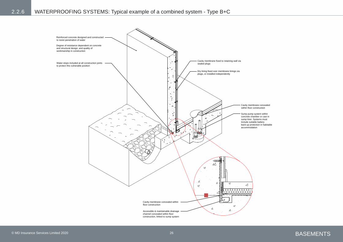
26© MD Insurance Services Limited 2020 BASEMENTS
Cavity membrane fixed to retaining wall viasealed plugs
Dry lining fixed over membrane linings viaplugs, or installed independently
Cavity membrane concealedwithin floor construction
Sump pump system withinconcrete chamber or cast insump liner. Systems mustinclude suitable batteryback-up protection in habitableaccommodation
Accessible & maintainable drainagechannel concealed within floorconstruction, linked to sump system
Cavity membrane concealed withinfloor construction
Reinforced concrete designed and constructedto resist penetration of water
Degree of resistance dependent on concreteand structural design, and quality ofworkmanship in construction
Water-stops included at all construction jointsto protect this vulnerable position
BASEMENTS
WATERPROOFING SYSTEMS: Typical example of a combined system - Type B+C2.2.6
© MD Insurance Services Limited 2020 26
WATERPROOFING SYSTEMS: Typical example of a combined system - Type B+C2.2.6

Premier Guarantee | 2 Shore Lines Building | Shore Road | Birkenhead | Wirral | CH41 1AUT 0800 107 8446 | E [email protected] | W www.premierguarantee.com
Technical Manual V13 - TS-011-13.00-010420 © Premier Guarantee 2020MD Insurance Services Ltd is the Scheme Administrator for the Premier Guarantee range of structural warranties. MD Insurance Services Ltd is authorised and regulated by the Financial Conduct Authority.
PG-Technical-Manual_v13-COVER.indd 20 17/03/2020 14:44