technical manual. start-up and operation manual...
TRANSCRIPT
CDP WALL-MOUNTED DEHUMIDIFIER – CDP SERIES · SWIMMING POOL DEHUMIDIFIER DESHUMIDIFICADOR MURAL CDP – SERIES CDP · DESHUMIDIFICADOR DE PISCINA
DESHUMIDIFICADOR MURAL CDP SERIES CDP · DESHUMIDIFICADOR DE PISCINA
V.2008.03.04
TECHNICAL MANUAL. START-UP AND OPERATION MANUAL TÉCNICO. PUESTA EN MARCHA Y FUNCIONAMIENTO
CDP-2 CDP-2+E CDP-2+A CDP-2+A PLUS CDP-3 CDP-3+E CDP-3+A CDP-3+A PLUS CDP-4 CDP-4+E CDP-4+A CDP-4+A PLUS CDP-5 CDP-5+E CDP-5+A CDP-5+A PLUS


DESHUMIDIFICADOR MURAL CDP SERIES CDP · DESHUMIDIFICADOR DE PISCINA
CDP WALL-MOUNTED DEHUMIDIFIER - CDP SERIES · SWIMMING POOL DEHUMIDIFIER DESHUMIDIFICADOR MURAL CDP - SERIES CDP · DESHUMIDIFICADOR DE PISCINA
TECHNICAL MANUAL. START-UP AND OPERATION MANUAL TÉCNICO. PUESTA EN MARCHA Y FUNCIONAMIENTO


1. INTRODUCCIÓN PÁG.07 2. MODELOS PÁG.08 3. CARACTERÍSTICAS GENERALES PÁG.09
3.1. DESCRIPCIÓN PÁG.09 3.2. DESCRIPCIÓN DEL EQUIPO PÁG.09 3.3. CUADRO ELÉCTRICO PÁG.09
4. CARACTERÍSTICAS TÉCNICAS PÁG.10 5. ESQUEMA DE DIMENSIONES PÁG.11 6. CARACTERÍSTICAS ELÉCTRICAS PÁG.12 7. REGULADOR PÁG.12 8. PRECAUCIONES GENERALES PÁG.14 9. COMPROBACIÓN DEL EMBALAJE PÁG.15 10. CONDICIONES DE TRABAJO PÁG.15 11. REQUISITOS Y OPERACIONES PREVIAS PÁG.16 12. CONEXIONES ELÉCTRICAS PÁG.16 13. CONEXIONES HIDRAÚLICAS PÁG.18 14. OPERACIÓN DE PUESTA EN MARCHA PÁG.18 15. MANTENIMIENTO PREVENTIVO PÁG.18 16. DESESCARCHE PÁG.19 17. AVERÍAS, SUS CAUSAS Y SOLUCIONES PÁG.19 18. CARGA GAS REFRIGERANTE PÁG.20 19. RECICLAJE DEL PRODUCTO PÁG.23 20. CERTIFICADO DE GARANTIA PÁG.24 21. ANEXO 1: ESQUEMA ELÉCTRICO PÁG.25
INDICE
español

1. INTRODUCTION PAGE.26 2. MODELS PAGE.27 3. GENERAL CHARACTERISTICS PAGE.28
3.1. DESCRIPTION PAGE.28 3.2. DESCRIPTION OF EQUIPMENT PAGE.28 3.3. ELECTRICAL PANEL PAGE.28
4. TECHNICAL CHARACTERISTICS PAGE.29 5. DIAGRAM OF DIMENSIONS PAGE.30 6. ELECTRICAL CHARACTERISTICS PAGE.31 7. REGULATOR PAGE.31 8. GENERAL PRECAUTIONS PAGE.33 9. PACKAGING INSPECTION PAGE.34 10. OPERATING CONDITIONS PAGE.34 11. REQUIREMENTS AND PROCEDURES PAGE.35 12. ELECTRICAL CONNECTIONS PAGE.35 13. HYDRAULIC CONNECTIONS PAGE.36 14. PROCEDURES AND START-UP PAGE.37 15. PREVENTIVE MAINTENCANCE PAGE.37 16. DEFROSTING PAGE.38 17. TROUBLESHOOTING GUIDE PAGE.38 18. REFRIGERANT GAS CHARGE PAGE.39 19. WARRANTY AND GENERAL CONDITIONS PAGE.42 20. APPENDIX 1: ELECTRICAL PANEL PAGE.44
GENERAL INDEX
english

7
ESPAÑOL
Le rogamos dedique unos minutos a la lectura de este manual para que pueda conocer todos los potenciales de la máquina, y tener en cuenta todas las circunstancias necesarias para su correcto y duradero funcionamiento.
DESHUMIDIFICADOR MURAL CDP
SERIES CDP 1. INTRODUCCIÓN.
Gracias por confiar en nuestros productos para la climatización de piscinas. La experiencia
acumulada por nuestra compañía durante más de 20 años en el mundo de la climatización de piscinas ha sido puesta a su servicio en este producto, en el que además incorporamos los avances técnicos que hacen de su equipo que puede solucionar de forma definitiva la climatización de su piscina.
LE RECOMENDAMOS ANOTE LOS SIGUIENTES DATOS
APARATO
Nº REFERENCIA MODELO
INSTALADOR
NOMBRE POBLACIÓN
DOMICILIO
TELÉFONO FECHA DE PUESTA EN MARCHA
USUARIO
NOMBRE POBLACIÓN
DOMICILIO
TELÉFONO FECHA DE PUESTA EN MARCHA
(A rellenar por el instalador) SELLO DEL INSTALADOR:
Para todas las máquinas, se deberá cumplimentar y enviar esta tarjeta de garantía para que entre en vigor

8
ESPAÑOL
2. MODELOS.
CÓDIGO MODELO 21202 CDP-2E
PATAS
BAT. ELECT. 3 KW
21203 CDP-3E BAT. ELECT. 3 KW
21204 CDP-4E BAT. ELECT. 4 KW
21205 CDP-5E BAT. ELECT. 5 KW
21402 CDP-2E
RUEDAS
BAT. ELECT. 3 KW
21403 CDP-3E BAT. ELECT. 3 KW
21404 CDP-4E BAT. ELECT. 4 KW
21405 CDP-5E BAT. ELECT. 5 KW
21406 CDP-2E
PARED
BAT. ELECT. 3 KW
21407 CDP-3E BAT. ELECT. 3 KW
21408 CDP-4E BAT. ELECT. 4 KW
21409 CDP-5E BAT. ELECT. 5 KW
24771 CDP-2A
PATAS
BAT. AGUA. 3.000 Kcal/h
24772 CDP-3A BAT. AGUA. 4.000 Kcal/h
24773 CDP-4A BAT. AGUA. 5.000 Kcal/h
24774 CDP-5A BAT. AGUA. 6.000 Kcal/h
24779 CDP-2A
PARED
BAT. AGUA. 3.000 Kcal/h
24780 CDP-3A BAT. AGUA. 4.000 Kcal/h
24781 CDP-4A BAT. AGUA. 5.000 Kcal/h
24782 CDP-5A BAT. AGUA. 6.000 Kcal/h
33939 CDP-2A PLUS
BAT. AGUA. 5.200 Kcal/h
33940 CDP-3A PLUS BAT. AGUA. 7.800 Kcal/h
33941 CDP-4A PLUS BAT. AGUA. 10.400 Kcal/h
33942 CDP-5A PLUS BAT. AGUA. 10.400 Kcal/h
33943 CDP-2E
EMPOTRADO
BAT. ELECT. 3 KW
33944 CDP-3E BAT. ELECT. 3 KW
33945 CDP-4E BAT. ELECT. 4 KW
33946 CDP-5E BAT. ELECT. 5 KW
33947 CDP-2A BAT. AGUA. 3.000 Kcal/h
33948 CDP-3A BAT. AGUA. 4.000 Kcal/h
33949 CDP-4A BAT. AGUA. 5.000 Kcal/h
33950 CDP-5A BAT. AGUA. 6.000 Kcal/h
33951 CDP-2A PLUS BAT. AGUA. 5.200 Kcal/h
33952 CDP-3A PLUS BAT. AGUA. 7.800 Kcal/h
33953 CDP-4A PLUS BAT. AGUA. 10.400 Kcal/h
33954 CDP-5A PLUS BAT. AGUA. 10.400 Kcal/h
33775
KIT DE RUEDAS INSTALACION CDP
33776 KIT DE PATAS INSTALACION CDP
33777 KIT DE PARED INSTALACION CDP

9
ESPAÑOL
3. CARACTERÍSTICAS GENERALES. DESCRIPCIÓN.
El deshumidificador CDP (Unidad deshumidificadora de piscina) se utiliza en instalaciones donde se requiere un control de humedad y temperatura individual de la zona, aprovechando el calor latente de vaporización y el propio rendimiento del equipo en calentar el aire del ambiente de pequeñas piscinas, bañeras, vestuarios y salas de baño. DESCRIPCIÓN DEL EQUIPO.
Bomba deshumidificadora mural monoblock construida en robusto y ligero diseño en ABS
Termo conformado resistente a la radiación solar. El color no se degrada, con gran ligereza y reducidas dimensiones. Equipado con los siguientes elementos:
◙ Batería evaporadora y condensadora monoblock construida en tubería de cobre con
aletas de aluminio lacado (especial para ambientes corrosivos). ◙ Compresor Hermético con protección interna, resistencia de carter y silenciador. ◙ Un circuito frigorífico de cobre nitrogenado, deshidratado y desoxidado. ◙ Ventilador centrífugo con diferentes caudales. ◙ Carga de gas freón R407C inofensivo para el Ozono (Ecológico). ◙ Bandeja de recogida de condensados fabricada en termo conformado ABS. ◙ Maquina mural con opcional de ruedas o patas. ◙ Válvula de expansión con equilibrador de presiones.
Control:
◙ Control a voluntad de la humedad y visualización en todo momento del parámetro. ◙ Minipresostatos de rearme automático. ◙ Termostato de desescarche. ◙ Opcional: Tarjeta horaria.
Montaje y Mantenimiento:
◙ Fácil y rápido montaje y acceso para mantenimiento. ◙ Tomas exteriores de obuses de carga para conectar manómetros. ◙ Fácil limpieza de filtros y de máquina.
Opcionales:
◙ Batería eléctrica con equipo de regulación y termostato de ambiente. ◙ Batería de A.C. válvula de 3 vías incorporada y termostato de ambiente. ◙ Patas o ruedas.
CUADRO ELÉCTRICO
Cuadro eléctrico con control total para garantizar un rendimiento óptimo con un mínimo consumo de energía en todo momento. La aplicación se basa en el control de una serie de elementos para mantener unas condiciones de temperatura y humedad en el aire de una instalación cubierta.

10
ESPAÑOL
El usuario partiendo de un Setpoint de humedad y temperatura, podrá definir el modo de funcionamiento de la unidad de forma manual o mediante un ajuste programado del día, hora y minuto del arranque así como de la parada, (opcional) solo las maquinas con tarjeta horaria.
Esta aplicación incorpora además un modo especial para ser configurado por la persona
encargada del mantenimiento y control de la unidad. Éste será capaz de variar parámetros tales como: diferencial de Setpoint, límites máximos de temperatura y tiempo de funcionamiento, temperatura de desescarche (ON/OFF), retardos, unidades,...
Incorpora una serie de salidas de alarma reflejadas en el display del FX 05, así como una
salida de alarma a relé.
ENTRADA ANALÓGICA ENTRADA DIGITAL SALIDA DIGITAL SALIDA ANALOGICA
AI1 Temperatura retorno DI1 Interruptor HP DO1 Alarma general AI2 Temperatura evaporador DI2 Interruptor LP DO2 (ON/OFF) Compresor AI3 Temperatura resistencias Válvula 3 vías.
DI4 Térmico compresor (Interno en el compresor)
DO3 (ON/OFF) Ventilador
AI4 Humedad relativa DO4 (ON/OFF )Resistencia Válvula 3 vías
4. CARACTERÍSTICAS TÉCNICAS.
CARACTERISTICAS MODELO CDP-2 CDP-3 CDP-4 CDP-5
Capacidad Deshumidificadora. 2,1 lts/h 3,1 lts/h 4,2 lts/h 5,1 lts/h Potencia Calorífica w (*) 4.277 W 5.313 W 7.068 W 8.473 W
COMPRESOR Unidades. 1 1 1 1 Tipo. Hermético Hermético Hermético Hermético Tensión. 220V II 380V III 220V II 380V III 220V II 380V III 220V II 380V IIIFrecuencia. 50 HZ 50 HZ 50 HZ 50 HZ Consumo. (Amp) 6,01 2 7,04 2,3 9.91 3,3 9,4 4,3 Potencia Nominal. (cv) 1 1 1/4 1 5/8 2
VENTILADOR Tipo. Centrífugo Centrífugo Centrífugo Centrífugo Unidades. 1 1 1 1 Caudal. (m3/h) 700 800 1.000 1.200 Consumo. (Amp) 1,1 1,1 1,1 1,1 Voltaje. 220 V 220 V 220 V 220 V
OTROS DATOS Consumo nominal 7,1 Amp 8,2 Amp 11,01 Amp 10,5 Amp Gas Refrigerante. R-407C R-407C R-407C R-407C
Peso en Kg + Batería Eléctrica 46 49 64 66
Peso en Kg + Batería A.C. 50 54 69 72 El cálculo de potencias se ha realizado con Temperatura de aire exterior de 28ºC de aire y un 75% de Humedad.

11
ESPAÑOL
OPCIONALES CDP-2+E CDP-3+E CDP-4+E CDP-5+E Batería Resistencia Eléctrica KW 3 3 4 4
OPCIONALES CDP-2+A CDP-3+A CDP-4+A CDP-5+A Batería Agua Caliente KW 3,5 4,65 5,8 7
Caudal de Primario l/h 150 200 250 300 Caída Presión de Agua m.c.d.a. 0.39 0.67 0.19 0.27
Diámetro Colector Pulgadas ½” ½” ¾” ¾”
OPCIONALES CDP-2+A PLUS
CDP-3+A PLUS
CDP-4+A PLUS
CDP-5+A PLUS
Batería Agua Caliente KW 6 9 12 12 Caudal de Primario l/h 270 400 600 600
Caída Presión de Agua m.c.d.a. 0,27 0,3 0,35 0,35 Diámetro Colector Pulgadas ¾” ¾” ¾” ¾”
5. ESQUEMA DE DIMENSIONES.
En las dimensiones que se reflejan en el cuadro siguiente están incluidos los diferentes
opcionales existentes.
DIMENSIONES (mm) CDP-2 CDP-3 CDP-4 CDP-5 Largo ( cota A) 1.350 1.350 1.670 1.670 Ancho (cota B) 360 360 360 360 Alto (Cota C) 610 610 610 610
Cuello impulsión 650x100 650x100 900x100 900x100 Cuello Aspiración 650x200 650x200 900x200 900x200 Cuellos (Cota E) 350 350 350 350
COTA A
COTA C
COTA B COTA E
1 y 2 - Conexiones primarias agua caldera3 - Alimentación eléctrica
23
121
3

12
ESPAÑOL
6. CARACTERÍSTICAS ELÉCTRICAS.
CARACTERISTICAS MODELO CDP-2+E CDP-3+E CDP-4+E CDP-5+E
Alimentación General Voltaje. (V) 220 II 380 III 220 II 380 III 220 II 380 III 220 II 380 III Sección (mm2) 4 4 6 6 Nº de Hilos. 2P+Tierra 4P+Tierra 2P+Tierra 4P+Tierra 2P+Tierra 4P+Tierra 2P+Tierra 4P+TierraINTENSIDAD ABSORBIDA (A) CDP-2+E CDP-3+E CDP-4+E CDP-5+E Compresor. 6,01 Amp 2 Amp 7,04 Amp 2,3 Amp 9.91 Amp 3,3 Amp 9,4 Amp 4,3 Amp Ventilador. 1,1 Amp 1,1 Amp 1,1 Amp 1,1 Amp Resistencias Eléctricas. 13,6 Amp 4,5 Amp 13,6 Amp 4,5 Amp 18,1 Amp 6 Amp 18,1 Amp 6 Amp Total 21 Amp 7,6 Amp 22 Amp 7,9 Amp 30 Amp 10 Amp 30 Amp 11,4 AmpCARACTERISTICAS CDP-2 (+A) CDP-3(+A) CDP-4(+A) CDP-5(+A) Alimentación General Voltaje. (V) 220 II 380 III 220 II 380 III 220 II 380 III 220 II 380 III Sección (mm2) 2.5 2.5 2.5 2.5 Nº de Hilos. 2P+Tierra 4P+Tierra 2P+Tierra 4P+Tierra 2P+Tierra 4P+Tierra 2P+Tierra 4P+TierraINTENSIDAD ABSORBIDA (A) CDP-2 (+A) CDP-3 (+A) CDP-4 (+A) CDP-5 (+A) Compresor. 6,01 Amp 2 Amp 7,04 Amp 2,3 Amp 9.91 Amp 3,3 Amp 9,4 Amp 4,3 Amp Ventilador. 1,1 Amp 1,1 Amp 1,1 Amp 1,1 Amp Total 7,11 Amp 3,1 Amp 8,14 Amp 3,4 Amp 11,01 Amp 4,4 Amp 10,5 Amp 5,4 Amp
7. REGULADOR. Funciones del frontal: INSTRUCCIONES DE FUNCIONAMIENTO: ◙ ARRANQUE Y PARADA DE LA UNIDAD: La unidad se arranca por medio de la tecla superior izquierda ON/OFF. Presionando la tecla durante dos segundos se encenderá la unidad (aparece una señal en la parte superior izda. del display). Repitiendo la misma operación se apagará la unidad.
El regulador muestra en el display por defecto la humedad relativa existente en el ambiente. Pulsando las teclas UP se visualizan además temperatura aire ambiente, el estado de la unidad (ON/OFF), temperatura del evaporador y temperatura resistencias.

13
ESPAÑOL
◙ MENU USUARIO
Pulsando de forma continua la tecla (ENTER) durante unos 5 segundos se accede al menú USUARIO. En este menú aparecen los siguientes parámetros:
SET: Permite fijar la temperatura deseada (SET-POINT Temperatura). Una vez alcanzada
la temperatura deseada en el local la función de Calentamiento del deshumidificador parará. SEH: Permite fijar la humedad relativa deseada (SET POINT Humedad). Una vez
alcanzada la humedad deseada en el local la función de Deshumidificación parará.
OPCIONAL: Solo los equipos con tarjeta horaria. hh: Ajuste de la hora (del 0 al 23) nn: Ajuste del minuto (del 0 al 59) dAY: Ajuste del día de la semana (del 0 al 6) (0 = Lunes / 6 = Domingo) Pr1: Programación de la unidad (0 = Programada / 1 = Manual)
Sí se elige Manual la máquina funcionará continuamente según los parámetros regulados
en SET y en SHE. No haciendo caso a los parámetros de programación. Sí se elige Programada la unidad funcionará según los parámetros regulados en SET y en
SHE, siempre dentro de los horarios programados. Fuera de los horarios programados no funcionará la unidad.
Si elegimos en PR = 1 no hace falta establecer los parámetros siguientes. La unidad ya está
ajustada. Si elegimos en PR = 0 programar los siguientes parámetros según necesidades. Ud: Día de funcionamiento de la unidad (1 = Funcionará todos los días. 2 = Funcionará de
Lunes a Viernes. 3 = Funcionará de Lunes a Sábado) Us: Selección de uno o dos Ciclos de programación ( 1 = Un Ciclo de programación. 2 =
Dos Ciclos de programación) Si elegimos en Us = 1 solo hará falta programar los parámetros DH1, Dn1, DH2 y Dn2. Sí elegimos en Us = 2 habrá que programar todos los parámetros siguientes: DH1: Hora de arranque de la unidad (1º ciclo) Dn1: Minuto de arranque de la unidad (1º ciclo) DH2: Hora de parada de la unidad (1º ciclo) Dn2: Minuto de parada de la unidad (1º ciclo) DH3: Hora de arranque de la unidad (2º ciclo) Dn3: Minuto de arranque de la unidad (2º ciclo) DH4: Hora de parada de la unidad (2º ciclo) Dn4: Minuto de parada de la unidad (2º ciclo)

14
ESPAÑOL
◙ LEDS INDICADORES:
En el display del regulador se encuentran tres pilotos luminosos con las siguientes indicaciones empezando de izquierda a derecha:
1. Estado de la unidad (ON/OFF) 2. Desescarche (ON/OFF) 3. Compresor (ON/OFF)
◙ ALARMAS:
La unidad mostrara los siguientes códigos en caso de alarmas: F1: Fallo sonda aire ambiente. F2: Fallo sonda evaporador. F3: Fallo sondas resistencias. F4: Fallo sonda Humedad Relativa. HP: Alarma disparo de alta presión. LP: Alarma disparo de baja presión. TH: Alarma disparo térmico compresor. AH: Alarma temperatura aire retorno máxima excedida. AL: Alarma temperatura aire retorno mínima excedida. HT: Alarma temperatura máxima de resistencias / Válvula agua superada.
◙ ANULACIÓN ALARMAS:
Para anular las alarmas que se hayan podido producir pulsar simultáneamente unos segundos las teclas UP & DOWN. Si el problema persiste, la alarma se mostrará inmediatamente. Mantenimiento:
Limpie la superficie del controlador con un paño suave, agua y jabón. No utilice detergentes abrasivos, gasolina, alcohol o disolvente. Advertencias:
El uso del equipo no respetando las instrucciones del fabricante, puede alterar los requisitos de seguridad del mismo. 8. PRECAUCIONES GENERALES.
Las operaciones de instalación, puesta en marcha y mantenimiento deben ser realizadas por personal cualificado.
No se debe de instalar estos equipos en entornos inflamables o explosivos.
Para cualquier operación de mantenimiento dentro de la máquina, se tendrá la precaución de desconectar la corriente eléctrica en el seccionador principal. En las operaciones de mantenimiento es obligatorio el uso de equipos de protección o seguridad como gafas, guantes, etc.

15
ESPAÑOL
Durante el funcionamiento de la máquina es habitual que las condensaciones que se producen en la batería evaporadora hagan que salga una cantidad de agua de la máquina que hay que evacuar. Las máquinas vienen provistas de un tubo de desagüe al efecto en la esquina de la carcasa trasera, que siempre debe quedar conectada a un aliviadero libre de cualquier obstrucción.
Esta agua de condensación no tiene que ser tratada de una forma especial. 9. COMPROBACIÓN DEL EMBALAJE.
Este equipo, se presenta con un EMBALAJE RECICLABLE capaz de resistir unas duras condiciones de transporte. No obstante, durante la instalación de la misma se deberá efectuar una comprobación visual de cualquier desperfecto, de forma que se evite cualquier mal funcionamiento posterior.
EL FABRICANTE no asumirá responsabilidad en ese caso.
En su interior encontrará los siguientes elementos: Equipo de climatización de piscinas Manual de Instalación. Garantía. 10. CONDICIONES DE TRABAJO.
Los parámetros físicos y químicos del agua deben de estar en los siguientes valores: ◙ PH..........................................7,2 a 7,8 ◙ Cloro residual........................ 1 a 2 ppm ◙ Alcalinidad............................ 80-125 ppm ◙ Sólidos totales disueltos........ </=3000 miligramos/litro ◙ Dureza................................... 200-300 ppm
Condiciones ambientales nominales de funcionamiento son:
◙ Tª aire instalación:................. 28º C ◙ Humedad:.............................. 75%
Las condiciones límites de funcionamiento dentro de las cuales está garantizado el buen
funcionamiento del equipo, son las siguientes: ◙ Tª mínima aire instalación: 18ºC
Por debajo de este valor salta alarma de funcionamiento.
Las condiciones de funcionamiento influirán en el rendimiento del equipo.
¡ATENCIÓN! ES MUY IMPORTANTE NO INCLINAR EL EMBALAJE, PARA LO QUE ÉSTE SE
DISEÑÓ CONVENIENTEMENTE. SIEMPRE SE DEBERÁ MANTENER EN POSICIÓN VERTICAL.
SI LA UNIDAD ESTÁ DAÑADA, O SI EL ENVIO NO ESTA COMPLETO, ANOTAR EN EL ALBARÁN DE ENTREGA Y ENVIAR UNA RECLAMACIÓN INMEDIATA A LA COMPAÑÍA QUE REALIZÓ EL ENVÍO.

16
ESPAÑOL
11. REQUISITOS Y OPERACIONES PREVIAS.
Es importante que la máquina se deposite en un apoyo horizontal y estable. Siempre se debe colocar la máquina en posición vertical y en un lugar protegido contra
inundaciones. La garantía no es de aplicación en caso contrario. El deshumidificador como todo aparato eléctrico debe estar instalado en el local a
tratar a más de 2 mts del vaso de piscina en sentido horizontal (Volumen 2), y 2,5 mts en sentido vertical.
La máquina está provista de un metro de manguera para la retirada de agua de
condensación. Durante su funcionamiento aparecerá agua de condensación producida al pasar el aire por
el evaporador. Para ello la máquina dispone un tubo de drenaje en la base. Prevea su evacuación. Esta máquina está pensada para trabajar en interiores, se debe de comprobar que la entrada
y salida de aire no estén obstruidas. Los obstáculos deben tener una distancia mínima. Se acompaña a la máquina con un juego de soportes de pared, suelo o ruedas.
12. CONEXIONES ELÉCTRICAS.
La acometida eléctrica deberá realizarse por el instalador teniendo en cuenta los siguientes puntos:
• Realizar la conexión según el esquema eléctrico incluido en este manual. • Colocar en la acometida general de fuerza un magnetotérmico curva U, que protegerá la
línea en caso de cortocircuito. • Colocar en la acometida general de fuerza un interruptor diferencial que protegerá la
instalación contra posibles derivaciones a tierra. La sensibilidad del diferencial será como mínimo de 30 mA.
• Interruptor diferencial. • Automáticos o Magnetotérmicos.
En la foto que se representa a continuación se indica esquemáticamente el modo en el que debe hacer la conexión

17
ESPAÑOL
• Antes de realizar la conexión del equipo se comprobará que la instalación eléctrica está desconectada y no hay tensión entre las fases de alimentación. • Conectar los cables de entrada de corriente a la borna de entrada de la máquina. • Conectar el cable de toma tierra en la borna correspondiente para ello. • Se debe cumplir en todo momento lo que deja reflejado la normativa vigente en cuanto a protecciones de las líneas eléctricas contra defectos y contactos directos o indirectos. • Verificar el apriete de todas las conexiones eléctricas. • Se comprobará que la resistencia eléctrica entre el suelo y cualquier terminal eléctrico es superior a 1 megaohmio. En caso contrario no se pondrá en marcha el equipo hasta que la perdida eléctrica no sea localizada y reparada. • En caso de que puedan existir fluctuaciones en la tensión de entrada, se recomienda instalar un sistema estabilizador de tensión para evitar daños al equipo.
Comprobar siempre que la tensión de red se corresponde con la de la máquina en la chapa de características técnicas. Se instalarán cables cuya sección cumpla con las normativas actuales e impidan un calentamiento de estos y una caída de tensión. A titulo orientativo se puede usar esta tabla para longitudes menores de 5 metros. En todo momento se cumplirá la normativa vigente y los criterios del proyectista.
ATENCIÓN: no modificar el tarado de los térmicos de protección de motores. En caso de duda dirigirse a su distribuidor.
MODELO CDP-2+E CDP-3+E CDP-4+E CDP-5+E
Alimentación General Voltaje. (V) 220 II 380 III 220 II 380 III 220 II 380 III 220 II 380 III Sección (mm2) 4 4 6 6 Nº de Hilos. 2P+Tierra 4P+Tierra 2P+Tierra 4P+Tierra 2P+Tierra 4P+Tierra 2P+Tierra 4P+Tierra CDP-2 (+A) CDP-3(+A) CDP-4(+A) CDP-5(+A) Alimentación General Voltaje. (V) 220 II 380 III 220 II 380 III 220 II 380 III 220 II 380 III Sección (mm2) 2.5 2.5 2.5 2.5 Nº de Hilos. 2P+Tierra 4P+Tierra 2P+Tierra 4P+Tierra 2P+Tierra 4P+Tierra 2P+Tierra 4P+Tierra

18
ESPAÑOL
13. CONEXIONES HIDRAÚLICAS.
Respetar en todo momento los diámetros de conexión hidráulica especificados para cada equipo.
Se deben instalar llaves de corte de paso total en cada uno de los elementos hidráulicos de la instalación y del equipo, de forma tal que permiten aislar cada uno de estos elementos en caso de necesidad (reparaciones, sustituciones, etc.) sin obligar el vaciado del circuito.
Se colocarán manguitos antivibratorios en la entrada y salida del equipo, para evitar vibraciones que produzcan fisuras o roturas en la instalación hidráulica.
En la conexión del equipo a la red hidráulica no deberemos forzar los tubos de Cobre. De esta forma evitaremos la rotura de los mismos. 14. OPERACIÓN DE PUESTA EN MARCHA.
En una primera operación se debe de verificar las conexiones eléctricas, comprobar la tensión del equipo y la tensión de la red.
Verificar que las conexiones hidráulicas están correctamente realizadas. Dar tensión al equipo conectando el interruptor general de fuerza externo a la unidad. Una
vez conectada la máquina verificar las intensidades absorbidas por las fases. Comprobar que el sentido de giro del ventilador es el correcto, en caso contrario invertir las
fases. Con el equipo en marcha comprobar las intensidades absorbidas por las resistencias y
motores eléctricos, comprobando que no sobrepasan los valores reflejados en la ficha técnica. Se deben de colocar manómetros de alta y baja presión en el circuito frigorífico y
comprobar la carga de gas (apartado Carga de Gas). Para realizar la parada del equipo desconectar el interruptor ON/OFF.
15. MANTENIMIENTO PREVENTIVO.
Deberá llevarse un historial de cada elemento atendido en el mantenimiento así como las actividades o reparaciones realizadas.
Las superficies de las carcasas exteriores pueden limpiarse con un paño y un limpiador no agresivo.
Realizar cualquier operación de mantenimiento DESCONECTANDO PREVIAMENTE LA ALIMENTACIÓN DE ELECTRICIDAD A LA MÁQUINA.
ATENCIÓN: cuando la instalación vaya a estar parada durante largos períodos de
tiempo, se aconseja retirar el equipo de la instalación o bien ventilar periódicamente la sala donde esté ubicado. Esto es debido al ambiente húmedo y clorado al que se ven expuestos los equipos, lo cual provoca el deterioro acelerado de los componentes electrónicos del mismo. La garantía no cubre aquellos casos en que el producto quede dañado por exposiciones prolongadas a un ambiente húmedo y clorado.
Batería evaporadora, condensadora y agua caliente:
Las baterías deben estar libre de obstáculos o polvo excesivo que impidan que el aire circule apropiadamente a través de la misma. Para efectuar su limpieza, utilice agua sin presión y detergentes no abrasivos o específicos para ello (consultar al fabricante).

19
ESPAÑOL
Compresor: Comprobar que el compresor se refrigera convenientemente con el gas circulante
(comprobar la carga de gas. Capitulo 14). Comprobar que el consumo no ha aumentado. Comprobar que las presiones de descarga del compresor no sean demasiado altas y que las
presiones de aspiración no sean demasiado bajas. Verificar que las sujeciones del compresor no están deterioradas. Verificar que no se forma escarcha en el compresor.
Ventilador: Comprobar anualmente los caudales del ventilador. Limpiar la suciedad de los alabes del ventilador así como la rejilla de protección.
Cuadro eléctrico: Verificar todas las conexiones eléctricas. Comprobar que no exista sobrecalentamiento en los terminales eléctricos. Verificar que los sistemas de protección funcionan correctamente. Verificar que el regulador funcionan correctamente contrastando su lectura con un
termómetro de mercurio (calibración de sonda).
16. DESESCARCHE.
La disminución de temperatura de evaporación por debajo de –5ºC provocará que el controlador de seguridad de evaporación corte el funcionamiento del compresor, que permanecerá desactivado hasta el rearme automático.
Este rearme se producirá cuando alcancemos el diferencial de temperatura. Durante este
periodo de tiempo el ventilador estará en funcionamiento. Cuando la temperatura disminuye y entra en funcionamiento el desescarche se enciende
una alarma en el display. No es conveniente que la máquina trabaje continuamente en estas condiciones. Recomendamos que desconecte la máquina cuando no la vaya a utilizar en periodos prolongados o en condiciones de baja temperatura. 17. AVERÍAS, SUS CAUSAS Y SOLUCIONES.
Las circunstancias por las que su deshumidificador podría no funcionar se detallan a continuación: El equipo no se pone en marcha:
La bobina del contactor no se activa: Comprobar que no está quemada en cuyo caso sustituir. Comprobar los enclavamientos que activan dicha bobina.
Térmico interno abierto: Comprobar el voltaje de la línea. Comprobar que las condiciones de trabajo son las correctas. Excesivo consumo del compresor. Cortocircuito en la línea del compresor.
Presostato de baja abierto: Comprobar el funcionamiento de este, sustituyéndolo si fuera necesario. Comprobar el correcto funcionamiento del ventilador. Comprobar la carga de gas del equipo (perdida de refrigerante, equipo con fugas) para solucionar esto ver apartado carga de gas.

20
ESPAÑOL
Comprobar que hay buena circulación de aire en la batería de intercambio. Comprobar que no hay obstrucciones en el circuito frigorífico eliminándola si ocurriera esto. Comprobar el correcto funcionamiento del capilar, sustituir en caso necesario.
Presostato de alta abierto: Comprobar el funcionamiento de este, sustituyéndolo si fuera necesario. Comprobar la carga de gas del equipo (exceso de refrigerante) para solucionar esto ver apartado carga de gas. Comprobar que no hay obstrucciones en el circuito frigorífico eliminándola si ocurriera esto.
Comprobar que hay una buena circulación de aire por la batería condensadora. Ciclo de desescarche: Las condiciones de aire ambiente no son adecuadas (temperaturas
demasiado bajas). La máquina no opera en estas condiciones, en este caso el regulador actuará sobre el compresor parándolo hasta que la temperatura ambiente sobrepase la temperatura mínima de funcionamiento. Nivel de aceite bajo:
Manchas de aceite en el equipo: Comprobar fugas en el circuito frigorífico reparándolas, verificar que los mínipresostatos de alta y baja están bien apretados, en caso de avería sustituirlos.
El equipo funciona en ciclos demasiado cortos:
Presostato de baja se abre y se vuelve a cerrar: Verificar los apartados del punto anterior “presostato de baja abierto”.
Contacto intermitente en el control de la máquina: Reparar o reemplazar el fallo del control eléctrico. Comprobar la sonda de humedad.
Comprobar que el equipo no es demasiado grande para la instalación. El equipo funciona continuamente:
Verificar el funcionamiento del humidostato reparándolo o sustituyéndolo si fuera necesario.
Contactos del contactor del compresor pegados: Comprobar el funcionamiento de la bobina del contactor y que no estén quemados los contactos.
La presión en la línea de aspiración es muy baja: Comprobar la carga de gas del equipo (perdida de refrigerante) para solucionar esto ver apartado de carga de gas. Verificar que no existen obstrucciones en el circuito frigorífico, capilar, etc, sustituir en caso de avería.
Comprobar que el equipo es lo suficientemente potente para las cargas térmicas existentes. Ruido excesivo:
Tornillos de sujeción del compresor o ventilador flojos: Apretar todos los elementos de fijación.
Comprobar el nivel de aceite del compresor. El compresor produce ruidos parecidos a golpes internos: Comprobar que no se trata de
golpe de líquido revisando el recalentamiento (ver apartado carga de gas). 18. CARGA DE GAS REFRIGERANTE.
Para realizar las tareas que detallamos a continuación se recomienda contactar con un especialista en equipos de calefacción o aire acondicionado.
Vacío del Circuito Frigorífico:
Es imprescindible antes de realizar la carga de gas hacer el vacío en el circuito frigorífico.

21
ESPAÑOL
-Primera operación de vacío: 1.- Conectar las mangueras del manómetro con los circuitos de la línea de presión de
aspiración (baja presión) y con la línea de presión de descarga (alta presión). 2.- Conectar la línea central del puente del manómetro a la bomba de vacío. 3.- Abrir todas las válvulas, incluyendo la solenoide y la válvula de regulación. 4.- Abrir las válvulas del puente del manómetro (LO = válvula baja / HI = válvula alta). 5.- Poner en funcionamiento la bomba de vacío y esperar hasta que el vacuómetro nos
indique el vacío. 6.- Cerrar todas las válvulas o llaves y desconectar la bomba de vacío.
Carga con Refrigerante:
El equipo emplea refrigerante R-407-C, que es una mezcla de 3 gases diferentes, que se comportan de forma distinta.
Es por esto que hay que tomar liquido de la botella de refrigerante e introducirlo en el circuito de baja presión a través de un cargador (sistema de expansión).
Después de haber puesto el circuito frigorífico bajo vacío, después de haber instalado el cargador y haber conectado las tuberías flexibles de los manómetros a los circuitos de alta y baja presión, realizaremos la carga de gas.
1.- Conectar la línea central del puente del manómetro a la botella de R-407 por la llave de
líquido. 2.- Abrir la llave de botella y purgar el trozo de tubería. 3.- Abrir la válvula de alta presión. 4-. Presurizar la instalación hasta que se iguale su presión con la de la botella. 5.- Cerrar la válvula del puente de manómetros. 6.- Poner en marcha la máquina. Posiblemente el presostato de baja se activará. Para
continuar con la carga, hay que desconectar el presostato de baja en el cuadro eléctrico (provisionalmente, mientras que se realiza la carga).
7.- Abrir la válvula de baja hasta que la presión este por encima del valor de disparo del presostato de baja.
8.- De vez en cuando, cerrar la válvula LO del puente de manómetros para leer la presión real de aspiración.
9.- Comprobar que la presión de descarga no aumenta por encima de la que se considera normal para las condiciones de trabajo.
10.- Cuando se haya introducido el peso correcto de refrigerante cerrar la válvula LO. 11.- Cuando la instalación esté trabajando según el diseño y condiciones de trabajo, cerrar
la válvula de botella de carga, desconectar las mangueras de los obuses teniendo cuidado con la purga de gas.
12.- Colocar los tapones en las tomas de aspiración y descarga del compresor. Detección de Fugas:
Las fugas pueden aparecer por diversas razones. La incidencia de las fugas puede ser reducida con una buena cualificación de los operarios y teniendo cuidado en el montaje.
Es importante prestar atención a los puntos que detallamos a continuación: * Buenas técnicas de soldadura. * Utilización de antivibratorios.
22
ESPAÑOL
* Utilización de componentes de buena calidad y diseñados para las condiciones de presión y temperatura de la instalación.
Síntomas de fugas Las fugas ocasionan la reducción de carga de refrigerante del equipo. Una carga baja puede
ser indicada:
◙ Temperatura del evaporador demasiado baja. Puede ser debido a una obstrucción de la línea de líquido o mal funcionamiento del capilar. Las consecuencias pueden ser graves, por ejemplo formación de hielo en el evaporador, etc.
◙ Ciclos muy cortos de funcionamiento del compresor. Esto puede ser debido también a
un mal funcionamiento del humidostato de control.
◙ Compresor sobrecalentado: La falta de gas provoca un caudal insuficiente de vapores para refrigerar el compresor. Esto puede ocasionar la apertura del térmico interno del compresor.
◙ El compresor funciona constantemente, no hay refrigerante suficiente como para
obtener las prestaciones adecuadas y al no alcanzar las temperaturas de consigan, el grupo no para.
En cualquier caso, es mejor no esperar a que aparezcan fugas, es por ello que la instalación
debe inspeccionarse regularmente. Métodos de Búsqueda de Fugas de Gas:
Existen en el mercado diferentes instrumentos de búsqueda de fugas, aunque no todos son
suficientemente sensibles para ciertos refrigerantes. Es muy importante seleccionar un detector adecuado para el refrigerante que incorpora el equipo y que se cumplan las operaciones de mantenimiento.
También se puede utilizar burbujas de jabón (spray de detergente líquido). Otros métodos como mecheros de antorcha halógena y aditivos en la instalación son
también recomendables para la localización de fugas.
El Gas R-407-C:
El R-407-C es un gas NO INFLAMABLE, no tiene punto de inflamación, no está sometido, por tanto, a la reglamentación de transporte de gases inflamables.
El R-407-C no es irritante para la piel, los ojos y las mucosas y no produce sensibilidad cutánea.
Tiene un bajo nivel de toxicidad tanto en exposición única como en exposiciones repetidas, no es mutágeno ni cancerígeno.
El R-407-C es susceptible de ocasionar congelaciones en contacto del gas licuado con la piel, debido a su inmediata evaporación.
Como todos los hidrocarburos, halogenados o no, el R-407-C es susceptible, a pesar de su bajo nivel de toxicidad, de ocasionar un estado preanestésico o anestésico general peligroso si se inhala una concentración muy elevada en medio cerrado.
23
ESPAÑOL
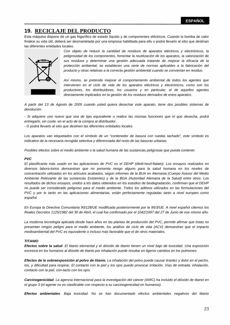
19. RECICLAJE DEL PRODUCTO Esta máquina dispone de un gas frigorífico de estado líquido y de componentes eléctricos. Cuando la bomba de calor finalice su vida útil, deberá ser desmantelada por una empresa habilitada para ello o podrá llevarlo al sitio que destinan las diferentes entidades locales.
Con objeto de reducir la cantidad de residuos de aparatos eléctricos y electrónicos, la peligrosidad de los componentes, fomentar la reutilización de los aparatos, la valorización de sus residuos y determinar una gestión adecuada tratando de mejorar la eficacia de la protección ambiental, se establecen una serie de normas aplicables a la fabricación del producto y otras relativas a la correcta gestión ambiental cuando se conviertan en residuo.
Así mismo, se pretende mejorar el comportamiento ambiental de todos los agentes que intervienen en el ciclo de vida de los aparatos eléctricos y electrónicos, como son los productores, los distribuidores, los usuarios y en particular, el de aquellos agentes directamente implicados en la gestión de los residuos derivados de estos aparatos.
A partir del 13 de Agosto de 2005 cuando usted quiera desechar este aparato, tiene dos posibles sistemas de devolución:
- Si adquiere uno nuevo que sea de tipo equivalente o realice las mismas funciones que el que desecha, podrá entregarlo, sin coste, en el acto de la compra al distribuidor. - O podrá llevarlo al sitio que destinen las diferentes entidades locales.
Los aparatos van etiquetados con el símbolo de un “contenedor de basura con ruedas tachado”, este símbolo es indicativo de la necesaria recogida selectiva y diferenciada del resto de las basuras urbanas.
Posibles efectos sobre el medio ambiente o la salud humana de las sustancias peligrosas que pueda contener.
PVC El plastificante más usado en las aplicaciones de PVC es el DEHP (dietil-hexil-ftalato). Los ensayos realizados en diversos labora-torios demuestran que no presenta riesgo alguno para la salud humana en los niveles de concentración utilizados en los artículos acabados, según informes de la BUA en Alemania (Cuerpo Asesor del Medio Ambiente Relevante de las sustancias Existentes) y de la BGA (Autoridad Alemana de la Salud) entre otros. Los resultados de dichos ensayos, unidos a los datos obtenidos en los estudios de biodegradación, confirman que el DEHP no puede ser considerado peligroso para el medio ambiente. Todos los aditivos utilizados en las formulaciones del PVC y por lo tanto en las aplicaciones alimentarías, están perfectamente reguladas tanto a nivel europeo como español.
En Europa la Directiva Comunitaria 90/128/UE modificada posteriormente por la 95/3/UE. A nivel español citemos los Reales Decretos 1125/1982 del 30 de Abril, el cual fue confirmado por el 1042/1997 del 27 de Junio de ese mismo año.
La moderna tecnología aplicada desde hace años en las plantas de producción del PVC, permite afirmar que éstas no presentan ningún peligro para el medio ambiente, los análisis de ciclo de vida (ACV) demuestran que el impacto medioambiental del PVC es equivalente o incluso más favorable que el de otros materiales.
TITANIO Efectos sobre la salud. El titanio elemental y el dióxido de titanio tienen un nivel bajo de toxicidad. Una exposición excesiva en los humanos al dióxido de titanio por inhalación puede resultar en ligeros cambios en los pulmones.
Efectos de la sobreexposición al polvo de titanio. La inhalación del polvo puede causar tirantez y dolor en el pecho, tos, y dificultad para respirar. El contacto con la piel y los ojos puede provocar irritación. Vías de entrada: inhalación, contacto con la piel, con-tacto con los ojos.
Carcinogenicidad. La agencia internacional para la investigación del cáncer (IARC) ha incluido el dióxido de titanio en el grupo 3 (el agente no es clasificable con respecto a su carcinogenicidad en humanos).
Efectos ambientales. Baja toxicidad. No se han documentado efectos ambientales negativos del titanio

24
ESPAÑOL
20. CERTIFICADO DE GARANTÍA
1. ASPECTOS GENERALES 1.1 De acuerdo con estas disposiciones, el vendedor garantiza que el producto correspondiente a esta garantía (“el producto”) no presenta ninguna falta de conformidad en el momento de su entrega. 1.2 El período de garantía para el producto es de dos (2) años, y se calculará desde el momento de entrega al comprador. 1.3 Si se produjera una falta de conformidad del Producto y el comprador lo notificase al vendedor durante el Período de Garantía, el vendedor deberá reparar o sustituir el Producto a su propio coste en el lugar donde considere oportuno, salvo que ello sea imposible o desproporcionado. 1.4 Cuando no se pueda reparar ni sustituir el Producto, el comprador podrá solicitar una reducción proporcional del precio o, si la falta de conformidad es suficientemente importante, la resolución del contrato de venta. 1.5 Las partes sustituidas o reparadas en virtud de esta garantía no ampliarán el plazo de la garantía del Producto original, si bien dispondrán de su propia garantía. 1.6 Para la efectividad de la presente garantía, el comprador deberá acreditar la fecha de adquisición y entrega del Producto. 1.7 Cuando hayan transcurrido más de seis meses desde la entrega del Producto al comprador y éste alegue falta de conformidad de aquél, el comprador deberá acreditar el origen y la existencia del defecto alegado. 1.8 El presente Certificado de Garantía no limita o prejuzga los derechos que correspondan a los consumidores en virtud de normas nacionales de carácter imperativo.
2. CONDICIONES PARTICULARES 2.1 La presente garantía cubre los productos a que hace referencia este manual. 2.2 El presente Certificado de Garantía será de aplicación únicamente en los países de la Unión Europea. 2.3 Para la eficacia de esta garantía, el comprador deberá seguir estrictamente las indicaciones del fabricante incluidas en la documentación que acompaña al Producto, cuando ésta resulte aplicable según la gama y modelo del Producto. 2.4 Cuando se especifique un calendario para la sustitución, mantenimiento o limpieza de ciertas piezas o componentes del Producto, la Garantía sólo será válida, cuando se haya seguido dicho calendario correctamente.
3. LIMITACIONES 3.1 La presente garantía únicamente será de aplicación en aquellas ventas realizadas a consumidores, entendiéndose “consumidor”, aquella persona que adquiere el Producto con fines que no entran en el ámbito de su actividad profesional. 3.2 No se otorga ninguna garantía respecto del normal desgaste por uso del Producto. En relación con las piezas, componentes y/o materiales fungibles o consumibles como pilas, bombillas etc, se estará a lo dispuesto en la documentación que acompañe al Producto, en su caso. 3.3 La garantía no cubre aquellos casos en que el Producto: (I) haya sido objeto de un trato incorrecto; (II) haya sido reparado, mantenido o manipulado por persona no autorizada o (III) haya sido reparado o mantenido con piezas no originales. Cuando la falta de conformidad del Producto sea consecuencia de una incorrecta instalación o puesta en marcha, la presente garantía sólo responderá cuando dicha instalación o puesta en marcha esté incluida en el contrato de compra-venta del Producto y haya sido realizada por el vendedor o bajo su responsabilidad
PRODUCTOS: DESHUMIDIFICADOR DE PISCINA
DECLARACIÓN CE DE CONFORMIDAD Los productos arriba enumerados se hallan conformes con:
Directiva de seguridad de máquinas 98/37/CEE Directiva de compatibilidad electromagnética 89/336/CEE
Directiva de equipos de baja tensión 97/23/CEE Directiva de equipos a presión 97/23/CEE
Normativa europea EN 603354-2-41 Directiva RoHS 2002/95 CE Directiva RAEE 2002/96 CE
25
ESPAÑOL
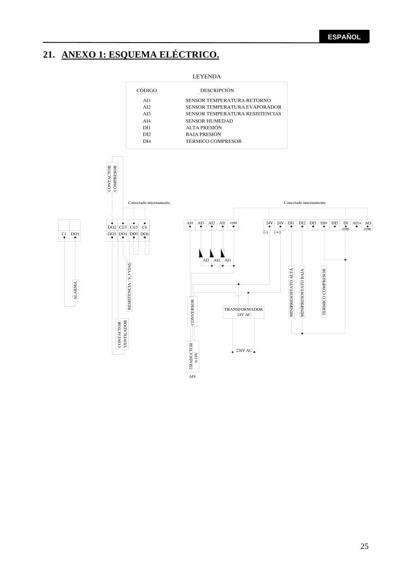
21. ANEXO 1: ESQUEMA ELÉCTRICO.
AI4
AI4
TR
AD
UC
TO
R
DO3
AL
AR
MA
DO1C1
RE
SIST
EN
CIA
/ V
.3 V
IAS
DO5DO4 DO6
DI4
AI3
DI1DI2
AI4
CÓDIGO
AI1AI2
TÉRMICO COMPRESOR
DO2
CO
MPR
ESO
R
Conectado internamente
C4/5C2/3 C6
DESCRIPCIÓN
SENSOR HUMEDAD
SENSOR TEMPERATURA RETORNO
SENSOR TEMPERATURA RESISTENCIASSENSOR TEMPERATURA EVAPORADOR
ALTA PRESIÓNBAJA PRESIÓN
LEYENDA
MIN
IPR
ESO
STA
TO
AL
TA
MIN
IPR
ESO
STA
TO
BA
JA
TE
RM
ICO
CO
MPR
ESO
R
TRANSFORMADOR
0-10
V
220V AC
CO
NV
ER
SOR
24V AC
DI5
AI3 AI2 AI1
AI1AI3 AI2 com
Conectado internamente
(+)(-)
24V24V DI1 DI3DI2 DI4 AOcomcom
DI AO+
CO
NT
AC
TO
R
CO
NT
AC
TO
RV
EN
TIL
AD
OR

26
ENGLISH
Please read this manual carefully. It will help you to learn the full potential of the equipment as well as the necessary procedures for its long-lasting and correct operation.
CDP WALL-MOUNTED DEHUMIDIFIER
CDP SERIES 1. INTRODUCTION.
Thank you for trusting in our products for the heating and cooling systems for swimming
pool. Through this product, we offer you our extensive experience of over 20 years in the heated swimming pool sector, where we strive to incorporate the latest technological innovations into all our products, making this equipment the definitive solution to your heated swimming pool needs.
WE RECOMMEND YOU FILL IN THE FOLLOWING INFORMATION
UNIT
SERIAL NUMBER MODEL
INSTALLER
NAME TOWN
ADDRESS
TELEPHONE START-UP DATE
USER
NAME TOWN
ADDRESS
TELEPHONE START-UP DATE
(To be filled by the installer) INSTALLER´S STAMP:
This warranty card should be filled and sent for all machines in order to be fully appicable

27
ENGLISH
2. MODELS.
CODE MODEL 21202 CDP-2E
WITH LEGS
ELECT. BAT. 3 KW
21203 CDP-3E ELECT. BAT. 3 KW
21204 CDP-4E ELECT. BAT. 4 KW
21205 CDP-5E ELECT. BAT. 5 KW
21402 CDP-2E
WITH WHEELS
ELECT. BAT. 3 KW
21403 CDP-3E ELECT. BAT. 3 KW
21404 CDP-4E ELECT. BAT. 4 KW
21405 CDP-5E ELECT. BAT. 5 KW
21406 CDP-2E
WALL-MOUNTED
ELECT. BAT. 3 KW
21407 CDP-3E ELECT. BAT. 3 KW
21408 CDP-4E ELECT. BAT. 4 KW
21409 CDP-5E ELECT. BAT. 5 KW
24771 CDP-2A
WITH LEGS
WATER. BAT. 3.000 Kcal/h
24772 CDP-3A WATER. BAT. 4.000 Kcal/h
24773 CDP-4A WATER. BAT. 5.000 Kcal/h
24774 CDP-5A WATER. BAT. 6.000 Kcal/h
24779 CDP-2A
WALL-MOUNTED
WATER. BAT. 3.000 Kcal/h
24780 CDP-3A WATER. BAT. 4.000 Kcal/h
24781 CDP-4A WATER. BAT. 5.000 Kcal/h
24782 CDP-5A WATER. BAT. 6.000 Kcal/h
33939 CDP-2A PLUS
WATER. BAT. 5.200 Kcal/h
33940 CDP-3A PLUS WATER. BAT. 7.800 Kcal/h
33941 CDP-4A PLUS WATER. BAT. 10.400 Kcal/h
33942 CDP-5A PLUS WATER. BAT. 10.400 Kcal/h
33943 CDP-2E
RECESSED
ELECT. BAT. 3 KW
33944 CDP-3E ELECT. BAT. 3 KW
33945 CDP-4E ELECT. BAT. 4 KW
33946 CDP-5E ELECT. BAT. 5 KW
33947 CDP-2A WATER. BAT. 3.000 Kcal/h
33948 CDP-3A WATER. BAT. 4.000 Kcal/h
33949 CDP-4A WATER. BAT. 5.000 Kcal/h
33950 CDP-5A WATER. BAT. 6.000 Kcal/h
33951 CDP-2A PLUS WATER. BAT. 3.000 Kcal/h
33952 CDP-3A PLUS WATER. BAT. 4.000 Kcal/h
33953 CDP-4A PLUS WATER. BAT. 5.000 Kcal/h
33954 CDP-5A PLUS WATER. BAT. 6.000 Kcal/h
33775
CPD WHEEL INSTALLATION KIT
33776 CDP LEG INSTALLATION KIT
33777 CDP WALL INSTALLATION KIT

28
ENGLISH
3. GENERAL CHARACTERISTICS.
3.1. DESCRIPTION.
The CDP dehumidifier (dehumidifying unit for swimming pools) is used in facilities requiring humidity control and individualised temperature management, taking advantage of the existing heat vapours and the equipment's heat output in order to warm the ambient air in small swimming pools, bathtubs, dressing rooms and bathrooms.
3.2. DESCRIPTION OF THE EQUIPMENT. Wall-mounted monoblock dehumidifying pump constructed of robust and lightweight thermal-
moulded ABS plastic, resistant to solar radiation. The colour does not fade, and it has a reduced size and is very lightweight. Equipped with the following:
◙ Monoblock evaporating and condensing coil constructed of copper tubing including
tempered aluminium fins (special for corrosive surroundings) ◙ Hermetically sealed compressor including internal protection, positive temperature
coefficient device and silencer. ◙ A cooling circuit made of heavy wall copper tubing, processed to repel rust. ◙ Centrifugal fan with various flow levels. ◙ Freon refrigerant gas R407C which is not harmful for the ozone (Ecological). ◙ Condensation plenum chamber made of thermal-moulded ABS plastic. ◙ Wall-mounted unit with legs or wheel mounting option. ◙ Expansion valve with pressure equaliser.
Control:
◙ Full control of humidity and complete visualisation of all parameters. ◙ Mini pressure switches with automatic reset. ◙ Defrosting thermostat. ◙ Optional: time control card.
Assembly and Maintenance:
◙ Quick and easy set-up and parts easily accessible for maintenance. ◙ External outlets for fitting and charging pressure gauges. ◙ Easy filter and machine cleaning.
Options:
◙ Electrical battery with built-in regulation and atmospheric thermostat. ◙ A.C. battery with built-in three-way valve and atmospheric thermostat. ◙ Legs or wheels.
3.3. ELECTRICAL PANEL.
Electrical control panel for complete process control and to guarantee optimum
performance with minimum power consumption at all times. The process control is based on various elements which are used to maintain temperature conditions and humidity in the air of a covered facility.

29
ENGLISH
Starting from a preset humidity and temperature Setpoint, the user can modify the operation of the unit manually or by setting the program to start or stop on a specified day, hour and minute (optional - for machines equipped with time card).
This application also offers the possibility of a special mode of programming which can be
done by the personnel in charge of the maintenance and control of the equipment. This personnel will be able to modify various parameters such as: Setpoint differential, maximum temperature and time limits, defrosting temperatures (ON/OFF), delayed operation, units, etc…
It also includes various alarms which can be viewed on the FX 05 display, as well as a relay
alarm.
ANALOG ENTRY DIGITAL ENTRY DIGITAL OUTPUT ANALOG OUTPUT
AI1 Return Temperature DI1 HP Switch DO1 General alarm AI2 Condenser Temperature DI2 LP Switch DO2(ON/OFF) Compressor AI3 3-way Resistance Valve Temperature
DI4 Thermal compressor (Inside the compressor)
DO3(ON/OFF) Fan
AI4 Relative Humidity DO4 (ON/OFF )3-way Resistance Valve
4. TECHNICAL CHARACTERISTICS.
CARACTERISTICS MODEL CDP-2 CDP-3 CDP-4 CDP-5
Dehumidification Capacity 2,1 lts/h 3,1 lts/h 4,2 lts/h 5,1 lts/h Power Output w (*) 4.277 W 5.313 W 7.068 W 8.473 W
COMPRESSOR Units. 1 1 1 1 Type Hermetic Hermetic Hermetic Hermetic Voltage. 220V II 380V III 220V II 380V III 220V II 380V III 220V II 380V IIIFrequency. 50 HZ 50 HZ 50 HZ 50 HZ Consumption. (Amp) 6,01 2 7,04 2,3 9.91 3,3 9,4 4,3 Nominal Power. (cv) 1 1 1/4 1 5/8 2
FAN Type. Centrifugal Centrifugal Centrifugal Centrifugal Units. 1 1 1 1 Flow. (m3/h) 700 800 1.000 1.200 Consumption. (Amp) 1,1 1,1 1,1 1,1 Voltage. 220 V 220 V 220 V 220 V
OTHER DATA Nominal consumption 7,1 Amp 8,2 Amp 11,01 Amp 10,5 Amp Refrigerant. R-407C R-407C R-407C R-407C
Weight in Kg + Electric Battery 46 49 64 66
Weight in Kg + A.C. Battery 50 54 69 72 * The calculation of power output was done based on exterior air Temperature of 28 ºC and 75% Humidity.

30
ENGLISH
OPTIONS CDP-2+E CDP-3+E CDP-4+E CDP-5+E Electrical Battery KW 3 3 4 4
OPTIONS CDP-2+A CDP-3+A CDP-4+A CDP-5+A Hot WATER Battery KW 3,5 4,65 5,8 7
Primary Flow l/h 150 200 250 300 Water Pressure m.c.d.a. 0.39 0.67 0.19 0.27
Manifold Diameter Inches ½” ½” ¾” ¾”
OPTIONS CDP-2+A PLUS
CDP-3+A PLUS
CDP-4+A PLUS
CDP-5+A PLUS
Hot Water Battery KW 6 9 12 12 Primary Flow l/h 270 400 600 600
Water Pressure m.c.d.a. 0,27 0,3 0,35 0,35 Manifold Diameter Inches ¾” ¾” ¾” ¾”
5. DIAGRAMS OF DIMENSIONS.
The different options available are reflected in the diagrams of the dimensions shown
below.
DIMENSIONS (mm) CDP-2 CDP-3 CDP-4 CDP-5 Length ( side A) 1.350 1.350 1.670 1.670 Width (side B) 360 360 360 360 Height (side C) 610 610 610 610
Supply duct 650x100 650x100 900x100 900x100 Return duct 650x200 650x200 900x200 900x200
Ducts (side E) 350 350 350 350
12
321
3
SIDE A
SIDE C
SIDE B SIDE E
1 and 2 - Water heater primary connections3 - Power supply

31
ENGLISH
6. ELECTRICAL CHARACTERISTICS.
CHARACTERISTICS MODEL CDP-2+E CDP-3+E CDP-4+E CDP-5+E
General Power Supply Voltage. (V) 220 II 380 III 220 II 380 III 220 II 380 III 220 II 380 III Section (mm2) 4 4 6 6
No. of wires 2P+ Ground
4P+ Ground
2P+ Ground
4P+ Ground
2P+ Ground
4P+ Ground
2P+ Ground
4P+ Ground
ABSORBED INTENSITY (A) CDP-2+E CDP-3+E CDP-4+E CDP-5+E Compressor. 6,01 Amp 2 Amp 7,04 Amp 2,3 Amp 9.91 Amp 3,3 Amp 9,4 Amp 4,3 Amp Fan. 1,1 Amp 1,1 Amp 1,1 Amp 1,1 Amp Electric Resistance. 13,6 Amp 4,5 Amp 13,6 Amp 4,5 Amp 18,1 Amp 6 Amp 18,1 Amp 6 Amp Total 21 Amp 7,6 Amp 22 Amp 7,9 Amp 30 Amp 10 Amp 30 Amp 11,4 AmpCHARACTERISTICS CDP-2 (+A) CDP-3(+A) CDP-4(+A) CDP-5(+A) General Power Supply Voltage. (V) 220 II 380 III 220 II 380 III 220 II 380 III 220 II 380 III Section (mm2) 2.5 2.5 2.5 2.5
No. of wires 2P+ Ground
4P+ Ground
2P+ Ground
4P+ Ground
2P+ Ground
4P+ Ground
2P+ Ground
4P+ Ground
ABSORBED INTENSITY (A) CDP-2 (+A) CDP-3 (+A) CDP-4 (+A) CDP-5 (+A) Compressor. 6,01 Amp 2 Amp 7,04 Amp 2,3 Amp 9.91 Amp 3,3 Amp 9,4 Amp 4,3 Amp Fan. 1,1 Amp 1,1 Amp 1,1 Amp 1,1 Amp Total 7,11 Amp 3,1 Amp 8,14 Amp 3,4 Amp 11,01 Amp 4,4 Amp 10,5 Amp 5,4 Amp
7. REGULATOR. Frontal features: INSTRUCTIONS FOR OPERATION: ◙ TURNING THE UNIT ON AND OFF: The unit is turned on by pressing the ON/OFF button on the upper left side of the display. Pressing the button for two seconds will turn the unit on (a lighted signal will appear on the upper left side of the display). Repeating this procedure will turn off the unit.

32
ENGLISH
The regulator will display the relative humidity of the atmosphere by defect. By pressing the UP button, you can also visualise ambient air temperature, the condition of the unit (ON/OFF), and the resistor temperatures.
◙ USER MENU
By pressing the (ENTER) button for 5 seconds, you can access the USER menu. This menu displays the following parameters:
SET: Allows for the setting of a specific temperature (SET-POINT Temperature). Once the
specific temperature is reached in the area, the Heating function of the Dehumidifier will turn off. SEH: Allows for the setting of a specific relative humidity (SET-POINT Humidity). Once
the specific humidity is reached in the area, the Dehumidifying function will turn off.
OPCIONAL: Only for units with time card. hh: Adjusts the hour (from 0 to 23) nn: Adjusts the minutes (from 0 to 59) dAY: Adjusts the day of the week (from 0 to 6) (0 = Monday / 6 = Sunday) Pr1: Unit programming (0 = Programmed / 1 = Manual)
If Manual operation is chosen, the machine will operate continuously, following the
specified parameters regulated by SET and SEH. Factory setting will be ignored. If Programmed operation is chosen, the machine will operate following factory settings of
SET and SEH, within the specified times. Outside of these times, the machine will not operate. If PR = 1 is chosen, it is not necessary to establish any parameters. The machine is already
adjusted. If PR = 0 is chosen, the following parameters must be programmed depending on your
needs. Ud: Days the unit should operate (1 = Every day. 2 = From Monday to Friday. 3 = From
Monday to Saturday). Us: Selection of one or two Programme Cycles (1 = One Programme Cycle. 2 = Two
Programme Cycles). If Us = 1 is chosen, only the DH1, Dn1, DH2 and Dn2 parameters need be programmed. If Us = 2 is chosen, the following parameters will need to be programmed: DH1: Hour of unit start-up (1st cycle) Dn1: Minute of unit start-up (1st cycle) DH2: Hour of unit shutdown (1st cycle) Dn2: Minute of unit shutdown (1st cycle) DH3: Hour of unit start-up (2nd cycle) Dn3: Minute of unit start-up (2nd cycle) DH4: Hour of unit shutdown (2nd cycle) Dn4: Minute of unit shutdown (2nd cycle)

33
ENGLISH
◙ INDICATOR LEDS:
Located on the regulator display, you will find three indicator leds indicating the following, from left to right:
4. Condition of the unit (ON/OFF) 5. Defrosting (ON/OFF) 6. Compressor (ON/OFF)
◙ ALARMS:
The unit will display the following alarm codes when necessary: F1: Failure ambient air indicator. F2: Failure evaporation indicator. F3: Failure resistance indicator. F4: Failure Relative Humidity indicator. HP: High pressure alarm. LP: Low pressure alarm. TH: Thermal compressor alarm. AH: Maximum air return exceeded alarm. AL: Minimum air return exceeded alarm. HT: Maximum resistance temperature exceeded / Water valve exceeded.
◙ ALARM CANCELLATION:
In order to cancel the alarm codes which may be displayed, push the UP & DOWN buttons simultaneously for a few seconds. If the problem still exists, the alarm will show it immediately. Maintenance:
Clean the surface of the controlling unit with a soft cloth, soap and water. Never use abrasive products, gasoline, alcohol or solvent. Warnings:
Not respecting the manufacturer's instructions regarding the use of this equipment may compromise the operation and safety of the equipment. 8. GENERAL PRECAUTIONS.
The installation, start-up and maintenance should be done by qualified personnel only. This equipment should not be exposed to inflammable substances or explosives. For any maintenance work done on the inside of the machine, proper care and precaution
should be taken to disconnect the main equipment from the power supply. For these types of operations, the use of protective equipment such as goggles and gloves is required.

34
ENGLISH
During operation of the equipment, it is normal that the condensation produced by the evaporation unit will produce a certain quantity of water which will have to be evacuated. The machines have an outlet tube for this reason on the corner of the back cover which should always be free of any obstruction and connected to a drain.
This condensation water does not have to be treated in any special manner. 9. PACKAGING INSPECTION.
This equipment is packaged using RECYCLABLE MATERIALS which can withstand even the most difficult transportation conditions. Nevertheless, an inspection of the packaging should be done upon receipt of the equipment in order to check for any damages, and to avoid incorrect operation of the equipment.
Talleres del Agua will not be held responsible in this case.
The package includes the following elements: Heating and cooling swimming pool’s equipment Owner's Manual. Warranty. 10. OPERATING CONDITIONS.
Water physical and chemical parameters must be in between: ◙ PH 7.2 to 7.8 ◙ Residual Cl 1 to 2 ppm ◙ Alkalinity 80 to 125 ppm ◙ Solids Lower than 3000 mg/l ◙ Ca 200 – 300 ppm
Normal ambient conditions for operation are:
◙ Air temp. installation: 28º C ◙ Humidity: 75%
The limits established for working conditions in order to guarantee the proper operation of
the equipment are: ◙ Minimum air temp. installation: 18ºC
Temperature below this will activate the alarm.
The operating conditions will affect the output of the equipment.
¡WARNING! IT IS VERY IMPORTANT TO KEEP THE PACKAGED EQUIPMENT UPRIGHT, AND THE
PACKAGING HAS BEEN SPECIFICALLY DESIGNED FOR THIS. ALWAYS MAINTAIN IT IN A VERTICAL POSITION.
IF THE UNIT IS DAMAGED, OR THE CONSIGNMENT IS INCOMPLETE, MAKE A NOTE OF IT ON THE CARRIER'S BILL OF LADING AND IMMEDIATELY MAKE A CLAIM TO THE COMPANY IN CHARGE OF SHIPPING.

35
ENGLISH
11. REQUIREMENTS AND PROCEDURES.
It is important that the equipment be installed on stable, horizontal ground. Always place the equipment vertically and far away from dangers of inundation. If not, the
warranty will be voided. Like any other electrical equipment, the dehumidifier should be installed more than 2
meters, horizontally, away from the pool (Volume 2) and 2,5 meters, vertically, away from the pool.
The machine is equipped with a one-meter hose for the elimination of condensed water. During operation, condensed water will appear, produced by the passing of air through the
evaporation unit. For this, the machine is equipped with a drainage tube on the base. Please plan ahead for the drainage.
This equipment is designed for interiors, the air inlets and outlets should be free of obstruction. Obstacles should be maintained at a distance.
The equipment includes a support kit for wall, floor or wheels. 12. ELECTRICAL CONNECTIONS.
The electrical installation should be done by qualified professionals, keeping in mind the following points: Connect the equipment following the wiring diagram included in this manual. Place a U-curve thermal-magnetic circuit breaker in the general power connection to protect the line in the case of a short in the circuit. Place a differential circuit breaker in the general power connection to protect the equipment from possible grounding problems. The differential breaker should be minimum 30 mA.
◙ Differential circuit breaker. ◙ Circuit breakers or thermal-magnetic circuit breaker.
The picture shown below is a diagram of how the connections should be made.

36
ENGLISH
Before installing the connections, be sure to disconnect the electricity so that the power supply is turned off. Connect the power supply wires to the machine's input terminal. Connect the grounding wire to its corresponding terminal. All local and national electricity codes concerning the protection of defects in electric power lines should be respected at all times during the electrical installation. Verify the torque of all electrical connections. The electrical resistance between the ground and any electric terminal will be verified to be over 1 megaohm. In the case of fluctuations in the power supply, a power supply stabilising system is recommended in order to protect the equipment. Always check that the supply voltage corresponds with the voltage which appears on the technical characteristics nameplate of the equipment. All wiring should comply with local and national electric codes and should not be prone to overheating and subsequent voltage failures. As a guide, you can use the table shown below for lengths of less than 5 meters. All local and national codes should be respected at all times.
MODEL CDP-2+E CDP-3+E CDP-4+E CDP-5+E
General Power Supply Voltage. (V) 220 II 380 III 220 II 380 III 220 II 380 III 220 II 380 III Section (mm2) 4 4 6 6
No. of wires 2P+ Ground
4P+ Ground
2P+ Ground
4P+ Ground
2P+ Ground
4P+ Ground
2P+ Ground
4P+ Ground
CDP-2 (+A) CDP-3(+A) CDP-4(+A) CDP-5(+A) General Power Supply Voltage. (V) 220 II 380 III 220 II 380 III 220 II 380 III 220 II 380 III Section (mm2) 2.5 2.5 2.5 2.5
No. of wires 2P+ Ground
4P+ Ground
2P+ Ground
4P+ Ground
2P+ Ground
4P+ Ground
2P+ Ground
4P+ Ground
13. HYDRAULIC CONNECTIONS.
Always respect the hydraulic connection diameters specified for each machine. A full-flow shut-off valve should be installed on each of the hydraulic elements in the
equipment, so that each of these may be isolated if needed (for repairs, substitutions, etc.) without the need to drain the circuit.
Anti-vibration dampers should be installed in the inlet and outlet of the machine, in order to avoid vibrations which may cause cracks or breakage in the hydraulic connections.
In order to avoid possible breakage, do not force the copper tubes connected to the water supply.

37
ENGLISH
14. PROCEDURES AND START-UP
When setting-up, the electrical connections, as well as the general power supply and voltage should be verified.
Verify that the hydraulic connections are correct. Give power to the equipment by connecting the general power switch on the outside of the
machine. Once the machine is connected, verify the intensity absorbed by the phases. Verify that the fan is operating in the correct direction, and if not, invert the phases. With the machine running, verify the intensities absorbed by the resistors and electric
motors, making sure they do not exceed the limits mentioned in the technical specification sheet. High and low pressure switches should be installed in the cooling circuit and verify the
refrigerant charge (Refrigerant Charge section). In order to shutdown the equipment, use the ON/OFF switch.
15. PREVENTIVE MAINTENANCE.
A record should be kept of each element repaired or substituted as well as of all maintenance and repairs.
The surface of the exterior panels may be cleaned with a soft cloth and non-abrasive cleaner.
DISCONNECT THE EQUIPMENT FROM THE POWER SUPPLY before performing any maintenance procedures.
WARNING: in the case that the equipment will be shutdown for a long period of time, we recommend you remove the equipment or periodically ventilate the area where the equipment is located. This is because the humid and often corrosive (chlorinated) areas where the equipment is located may lead to premature deterioration of the electrical components. The warranty does not cover damage due to prolonged exposure to humid and corrosive atmospheres.
Evaporation unit, condensers and hot water:
The units should be kept clean and free of obstacles which may hinder the circulation of air through them. In order to clean them, use water (no pressure) and non-abrasive detergents or cleaning liquids made specifically for them (consult the manufacturer). Compressor:
Verify that the compressor refrigerates adequately with the circulating gas (verify the refrigerant charge. Section 14).
Verify that the power consumption has not increased. Verify that the compressor discharge pressure is not too high and that the intake pressure is
not too low. Verify that the compressor fasteners are not deteriorated. Verify that no frost develops on the compressor.
Fan: Verify the flows of the fan each year. Clean the louvers of the fan as well as the protection grill regularly.
Electrical panel: Verify all electrical connections. Verify that there is no over-heating of the electrical terminals. Verify that the protection systems operate correctly.
38
ENGLISH
Verify that the regulator operates correctly and verify the temperature with a mercury thermometer (calibration probe).
16. DEFROSTING.
A decrease in evaporation temperature to below -5 ºC will result in the shutting down of the compressor by the evaporation security controlling unit, and will remain off until the automatic reset takes place.
This reset will take place when the differential temperature is reached. During this time, the
fan will operate normally. When the temperature decreases and defrosting begins, an alarm indicator will appear on
the display. It is not advisable that the machine operate continuously under these conditions. We recommend you disconnect the equipment if it will not be in use during prolonged periods of time or under conditions of low temperatures. 17. TROUBLESHOOTING GUIDE.
The reasons why your dehumidifier may not function properly are mentioned below: The unit does not start:
Coil contactor does not activate: Verify that it is not burned, and replace it if it is. Verify the terminals which activate the coil.
Internal thermal switch tripped: Verify the voltage of the line. Verify that the operating conditions are correct. Excessive compressor consumption. Short circuit in the compressor.
Low pressure switch tripped: Verify the switch operates correctly, replacing it if necessary. Verify that the fan is operating correctly. Verify the refrigerant charge of the equipment (refrigerant leak, loss of refrigerant fluids) in order to solve this problem; please refer to the refrigerant charge section.
Verify that there is sufficient ventilation around coils. Verify that there are no obstructions in the cooling circuit and eliminate them if there are. Verify that the switch wires function properly and replace them if necessary.
High pressure switch tripped: Verify that the pressure switch operates correctly and substitute if necessary. Check the refrigerant charge (excess refrigerant) in order to solve this please refer to the refrigerant charge section. Check for any obstruction of the cooling circuit and eliminate the obstruction if necessary.
Verify that there is sufficient ventilation around the condensers. Defrost cycle: The ambient conditions are not correct (temperatures are too low). The
machine will not operate under these conditions; in this case, the regulator will affect the condenser, shutting it off until the ambient temperature returns to the minimum required limits for correct operation. Low oil level:
Oil stains on the equipment: Check for leaks in the cooling circuit and repair them if necessary, check the torque on the high and low mini pressure switches, and replace them if necessary.

39
ENGLISH
The equipment operates on cycles which are too short:
The low pressure switch opens then closes again: Verify the points mentioned in the "low pressure switch tripped" section above.
Intermittent contact on machine control unit: Repair or replace the faulty electrical part. Check the humidity.
Make sure the equipment is not too large for the facilities. The equipment does not shut down:
Verify that the humidistat functions properly, repairing or replacing it if necessary. Compressor contactor contacts are stuck together: Check that the coil is functioning
properly and that the contacts are not burned. The pressure of the intake duct is too low: Check the refrigerant charge of the equipment
for leaks, to solve this problem please refer to the refrigerant charge section. Check that there are no obstructions in the cooling circuit, lines, etc. and replace if necessary.
Verify that the equipment is powerful enough for the existing thermal conditions. Excessive noise:
The fastening screws of the compressor or fan are loose: Tighten all the fastening elements. Check the compressor oil level. The compressor produces internal bumping noises: Check that the noise does not come
from any fluid leak from overheating (see section of refrigerant charge). 18. REFRIGERANT CHARGE. For the procedures described below, we recommend you contact a professional specialised in
heating and air conditioning units. Draining the Cooling Circuit:
It is imperative to drain the cooling circuit before charging the refrigerant. -First draining procedure: 1.- Connect the gauge tubes to the intake pressure lines of the circuit (low pressure) and to
the return pressure lines (high pressure). 2.- Connect the main line of the gauge to the vacuum pump. 3.- Open all the valves, including the solenoid and the regulating valves. 4.- Open the valves of the gauge (LO = low pressure valve / HI = high pressure valve). 5.- Activate the vacuum pump and wait until the circuit is completely drained. 6.- Close all valves or stopcocks and disconnect the vacuum pump.
Refrigerant Charge:
The equipment uses R-407-C class refrigerant, which is a blend of 3 different gases with different properties.
This is the reason why the gas taken from the refrigerant bottle must be introduced in the low-pressure circuit by means of a charger (expansion system).
After having discharged the cooling circuit, and after having installed the charger and connected the flexible tubes of the gauge to the high and low-pressure circuits, we can proceed with the charge:

40
ENGLISH
1.- Connect the main line of the gauge to the R-407 bottle stopcock. 2.- Open the bottle stopcock and purge the section of tubing. 3.- Open the high-pressure valve. 4-. Pressurise the equipment to equal the pressure of the bottle. 5.- Close all gauge valves. 6.- Start the machine. The low-pressure switch may be activated. To continue with the
charge, you must disconnect the low-pressure switch in the electrical panel (just while the charging operation is underway).
7.- Open the low-pressure valve until the pressure is above the trip point of the low-pressure switch.
8.- Once in a while, close the LO valve of the gauges in order to confirm the real pressure of intake.
9.- Verify that the outflow pressure is not above the normal range for normal working conditions.
10.- When the correct weight of refrigerant has been charged, close the LO valve. 11.- When the equipment is functioning according to the specified working conditions,
close the valve of the charging bottle and disconnect the tubes taking precautions regarding gas purge.
12.- Place the caps on the supply and return lines of the compressor. Detecting Leaks:
Leaks may appear due to various reasons. Leakage risk may be greatly reduced if the equipment is correctly installed by qualified personnel and by taking certain precautions in the assembly of the equipment.
The following points are especially important: * Good welding technique. * Use of antivibration tools. * Use of top-quality components and tools designed specifically for the pressure and
temperature conditions of the equipment. Symptoms of a leak Leaks will cause a decrease in the refrigerant charge in the equipment. Low refrigerant
charge may be the cause of:
◙ The temperature of the evaporating unit is too low. This may be caused by an obstructed fluid line or the incorrect operation of a capillary. The consequences may be very serious, for example ice may form on evaporating unit, etc.
◙ The compressor is functioning on cycles which are too short. This may also be due to
incorrect functioning of control humidistat.
◙ Compressor is overheated: low gas charge makes for insufficient flow of vapours to cool the compressor. This may cause the tripping of the internal thermal indicator of the compressor.
◙ The compressor operates continuously, there is not enough refrigerant to obtain the
desired results, and since the specified temperatures are not reached, the equipment does not shut down.

41
ENGLISH
In any case, it is better not to wait until a leak appears, and for this reason, it is recommended that the equipment be serviced regularly. Methods for Searching for a Gas Leak:
There are various tools on the market used in order to detect leaks, although not all of them
are sufficiently sensitive to certain types of refrigerants. It is very important to choose an adequate detector for the refrigerant used for this equipment and that the maintenance guidelines by followed.
You can also use soap bubbles (liquid detergent in a spray bottle) to detect leaks. Other methods such as halogen lighters and additives may also be used to detect leaks.
The R-407-C Gas:
The R-407-C is NOT AN INFLAMMALBE gas; it has no flash point, and so is not subjected to the rules and regulations of the transportation of inflammable gases.
The R-407-C does not irritate the skin, eyes or mucous membranes and does not produce and side-effects.
It has a very low level of toxicity for one or many repeated exposures; it does not cause cancer or mutations.
The R-407-C is susceptible may cause freezing if it comes into contact with the skin, due to its immediate evaporation.
As with all hydrocarbons, whether they are halogenated or not, the R-407-C gas may, although it has a very low level of toxicity, cause anaesthetic or preanaesthetic conditions if inhaled deeply and within a closed area.

42
ENGLISH
19. PRODUCT RECYCLING
This unit has a refrigeration gas in liquid state and electrical components. When the heat pump reaches the end of its service life, it should be dismantled by an authorised company or may be transported to the place assigned by the corresponding local authorities.
With the aim of reducing the amount of electrical and electronic equipment residues and the danger of their components, to promote the recycling of the equipment and the appreciation of their residues, and to determine a suitable management that attempts to improve the effectiveness of the environmental protection, a series of regulations applicable to the manufacturing of the product and others related to the correct environmental management when they become residues have been implemented.
It is also envisaged to improve the environmental behaviour of all the agents involved in the service life of the electrical and electronic equipment, such as the producers, distributors, users and, specially, those agents directly involved in the management of the residues derived from this equipment. As of 13 August 2005, when you wish to throw away this unit, you have two possible return systems: - if you acquire a new one that is of an equivalent type or it has the same functions as the one thrown away, you could hand it over at no cost to the distributor. - or you could take it to the place so selected by the local authorities. The units are labelled with the symbol of a “crossed out wheeled rubbish container “. This symbol denotes the need for its selective and differentiated collection from the rest of urban rubbish. Possible effects over the environment or human health of the dangerous materials it may contain. PVC The most used plastifying agent in the different PVC applications is the DEHP (di-2-ethyl hexyl phthalate). The tests conducted in different laboratories demonstrate that it does not present risks for human health in the concentration levels so used in finished articles, according to the information from the German BUA (Advisory Body for the Relevant Environment of the Existing Substances) and the VGA (German Health Authority) among others. The results of these tests, together with the data collected in biodegradation studies, confirm that the DEHP cannot be considered dangerous for the environment. All additives used in the PVC formulations and therefore in the food industry applications are perfectly regulated at both European and Spanish level.
In Europe, the EC Directive 90/128/EU, later modified by the 95/3/EU. In Spain, we should mention the Royal Decrees 1125/1982 of 30 April 1982, later confirmed by the 1042/1997 of 27 June 1982.
Modern technology applied for years in the PVC production plants allow us to state that they do not mean a danger for the environment. The service life analyses (SLA) demonstrate that the environmental impact of the PVC is equivalent or even more favourable than those corresponding to other materials.
TITANIUM
Health effects. Elemental titanium and titanium dioxide are of a low order of toxicity. Humans overexposed to titanium dioxide via inhalation can develop slight changes in lungs.
Effects of overexposure to titanium powder. Dust inhalation may cause tightness and pain in chest, coughing, and difficulty in breathing. Contact with skin or eyes may cause irritation. Routes of entry: Inhalation, skin contact, eye contact.
Carcinogenicity. The International Agency for Research on Cancer (IARC) has listed titanium dioxide within Group 3 (The agent is not classifiable as to its carcinogenicity to humans.)
Environmental effects. Low toxicity. No negative environmental effects of titanium have been reported.

43
ENGLISH
20. WARRANTY CERTIFICATE
1. WARRANTY COVERAGE 1.1 In accordance with these provisions, the salesman guarantees that the product corresponding to this warranty (“the product”) does not present any non-conformance at the moment of its delivery. 1.2 The warranty period of the product is of two (2) years and it will take effect as of the time of delivery to the buyer. 1.3 If a Product non-conformance occurs and the buyer notifies it to the salesman during the Warranty Period, the salesman should repair or replace the Product at his own cost in the appropriate place, unless it is impossible or disproportionate. 1.4 When the Product cannot be repaired nor be replaced, the buyer shall be able to ask for a proportional price reduction or, if the nonconformance is sufficiently important, the discharge of the sales contract. 1.5 The replaced or repaired parts by virtue of this warranty will not extend the warranty term of the original Product, although they will have its own warranty. 1.6 For the effectiveness of this warranty, the buyer will have to credit the acquisition date and delivery date of the Product. 1.7 When the delivery of the Product to the buyer had been more than six months before and the buyer alleges non-conformance with the Product, the buyer will have to prove the origin and existence of the alleged fault. 1.8 The present Warranty Certificate does not limit or prejudges the rights the consumers are entitled by virtue of local prevailing and applicable regulations. 2. CONDITIONS TO WARRANTY 2.1 This warranty covers the products referred to in this manual. 2.2 This Warranty Certificate will be solely applicable in the countries of the European Union. 2.3 For the effectiveness of this warranty, the buyer will have to strictly follow the manufacturer instructions included in the documentation enclosed with the Product, whenever this warranty is applicable according to the Product range and model. 2.4 When a calendar for the substitution, maintenance or cleaning of certain parts or components of the Product is specified, the Warranty will only be valid when the calendar has been observed. 3. LIMITACIONES 3.1 This warranty will be solely applicable to those sales to consumers, being understood “consumers” as those people who acquire the Product with a purpose that does not fall within the scope of their professional activity. 3.2 No warranty is granted referred to the wear and tear caused by the use of the Product. In relation to the parts, components and/or consumable materials such as batteries, light bulbs etc, it will refer to the provisions of the documentation enclosed with the Product, when applicable. 3.3 The warranty does not cover those cases where the Product: (I) has been incorrectly treated; (II) has been repaired, maintained or manipulated by a nonauthorized person, or (III) has been repaired or maintained with nonoriginal pieces When the non-conformance of the Product is a consequence of an incorrect installation or start-up, this warranty will only cover those installations or start-ups included in the contract of sale of the Product and carried out by the salesman or under his/her responsibility.
PRODUCTS: SWIMMING POOL DEHUMIDIFIER DECLARATION OF CONFORMITY
The products above listed are in conformity with the following: Machinery Directive 89/392/EEC,
Electromagnetic Compatibility Directive 89/336/EEC, and its amendments. Low Voltage Equipment Directive 73/23/EEC.
European Standard EN 60335-2-41. RoHS Directive 2002/95 EC.

44
ENGLISH
21. APPENDIX 1: ELECTRICAL DIAGRAM.
NOS RESERVAMOS EL DERECHO DE CAMBIAR TOTAL O PARCIALMENTE LAS CARACTERÍSTICAS DE NUESTROS ARTÍCULOS O CONTENIDO DE ESTE DOCUMENTO SIN PREVIO AVISO.
WE RESERVE THE RIGHT TO CHANGE ALL OR PART OF THE FEATURES OF THE ARTICLES OR CONTENTS OF THIS DOCUMENT, WITHOUT PRIOR NOTIC
AI4
AI4
DO3DO1C1 DO5DO4 DO6
DI4
AI3
DI1DI2
AI4
AI1AI2
DO2 C4/5C2/3 C6
220V AC
24V AC
DI5
AI3 AI2 AI1
AI1AI3 AI2 com
(+)(-)
24V24V DI1 DI3DI2 DI4 AOcomcom
DI AO+
LEGEND
DESCRIPTION
RETURN TEMPERATURE SENSOREVAPORATOR TEMPERATURE SENSORRESISTENCE TEMPERATURE SENSORS
HUMIDITY SENSORHIGH PRESSURELOW PRESSURECOMPRESSOR CONTACTO
AL
AR
M
CO
MPR
ESS
OR
CO
NT
AC
TO
R
CO
NV
ER
TE
RV
OL
TA
GE
0-10
VT
RA
NSL
AT
OR
TRANSFORMER
INTERNALLY CONNECTED INTERNALLY CONNECTED
CO
MPR
ESS
OR
TH
ER
MA
L S
WIT
CH
LO
W-P
RE
SSU
RE
SW
ITC
H
HIG
H-P
RE
SSU
RE
SW
ITC
H
CO
NT
AC
TO
RV
EN
TIL
AD
OR R
ESI
STE
NC
E /
3 W
AY
S V
AL
VE
CODE