technical manual operator’s, unit and direct … · direct support maintenance manual for...
TRANSCRIPT

TM 10-5411-235-13
TECHNICAL MANUAL
OPERATOR’S, UNIT AND DIRECT SUPPORT MAINTENANCE MANUAL
FOR LIGHTWEIGHT MULTIPURPOSE SHELTER (LMS)
LMS TYPE 1 NSN 5411-01-473-5051
DISTRIBUTION STATEMENT A – Approved for public release; distribution is unlimited.
HEADQUARTERS, DEPARTMENT OF THE ARMY
31 AUGUST 2003

TM 10-5411-235-13
a /(b Blank)
WARNING SUMMARY
WARNING
LMS Shelter weighs in excess of 600 lbs. Use safety precautions and proper lifting equipment when installing, removing shelter from HMMWV. Failure to comply could result in serious injury or death.
WARNING
Do not breathe cleaning solvent vapors for long periods or use solvent near open flames. To avoid illness, explosion or fire, only use solvent in well-ventilated areas, away from open flames.
WARNING
Do not use diesel fuel, gasoline or benzene (Benzoil) for cleaning. These items are highly flammable and, if ignited, can cause injury or death to personnel and damage to equipment.
WARNING
Use extreme care with cleaning solvents. Cleaning solvents evaporate quickly and can irritate exposed skin if solvents contact the skin. In cold weather, contact of exposed skin to cleaning solvents can cause frostbite.
WARNING
The LMS door weighs 40 lbs +/-2 lbs. Use safety precautions outlined and proper lifting equipment when removing and/or installing door.
WARNING
Do not allow personnel in closed shelter when HMMWV is in operation. Possible exposure to carbon monoxide fumes could result in serious illness or death.
CAUTION
Do not wear jewelry when performing maintenance. Jewelry can get caught and cause severe injury.

TM 10-5411-235-13
CHANGE HEADQUARTERS, DEPARTMENT OF THE ARMY NO. 1 WASHINGTON, DC, 31 AUGUST 2005
TECHNICAL MANUAL
UNIT, DIRECT SUPPORT AND GENERAL SUPPORT MAINTENANCE MANUAL FOR
LIGHTWEIGHT MULTIPURPOSE SHELTER (LMS)
LMS TYPE 1
NSN: 5411-01-473-5051
DISTRIBUTION STATEMENT A: - Approved for public release; distribution is unlimited. TM 10-5411-235-13, 31 August 2003, is updated as follows: 1. File this sheet in front of the manual for reference. 2. This change implements Army Maintenance Transformation and changes the
Maintenance Allocation Chart (MAC) to support Field and Sustainment Maintenance.
3. New or updated change information is indicated by a vertical bar in the outer
margin of the page. 4. Remove old pages and insert new pages as indicated below:
Remove Pages Insert Pages A/(B Blank) A/(B Blank) DA 2028 Front/Back DA 2028 Front/Back DA 2028 Front/Back
5. Replace the following work packages with their revised version:
Work Package Number
Work Package Number
Work Package Number
Work Package Number
WP 0041 00 WP 0042 00

ARMY TM 10-5411-235-13 C1
By Order of the Secretary of the Army:
PETER J. SCHOOMAKER General, United States Army Chief of Staff
Official:
SANDRA R. RILEY Administrative Assistant to the Secretary of the Army 0521013 Distribution: To be distributed in accordance with initial distribution number (IDN) 256188 requirements for TM 10-5411-235-13.

TM 10-5411-235-13
A/(B Blank) Change 1
INSERT LATEST CHANGED PAGES/WORK PACKAGES. DESTROY SUPERSEDED DATA. LIST OF EFFECTIVE PAGES/WORK PACKAGES
NOTE: The portion of text affected by the update is indicated by a vertical line in the outer margins of the
page. Updates to illustrations are indicated by miniature pointing hands or vertical lines in the outer margins of the page in the area of the illustration changed. Zero in the “Change No.” column indicates an original page or work package.
Dates of issue for original manual and changed pages / work packages are:
Original 31 August 2003 Change 1 31 August 2005
TOTAL NUMBER OF PAGES FOR FRONT AND REAR MATTER IS 24 AND TOTAL NUMBER OF WORK PACKAGES IS 44, CONSISTING OF THE FOLLOWING:
Page/WP No. Change No.
Page/WP No. Change No.
Front Cover 0 WP 0021 00 (4 pgs) 0 a/(b Blank) 0 WP 0022 00 (4 pgs) 0 i - iv 0 WP 0023 00 (2 pgs) 0 Chp 1 title page 0 WP 0024 00 (2 pgs) 0 WP 0001 00 (6 pgs) 0 WP 0025 00 (2 pgs) 0 WP 0002 00 (2 pgs) 0 WP 0026 00 (2 pgs) 0 WP 0003 00 (2 pgs) 0 Chp 5 title page 0 Chp 2 title page 0 WP 0027 00 (2 pgs) 0 WP 0004 00 (2 pgs) 0 WP 0028 00 (6 pgs) 0 WP 0005 00 (4 pgs) 0 WP 0029 00 (6 pgs) 0 WP 0006 00 (2 pgs) 0 WP 0030 00 (2 pgs) 0 WP 0007 00(2 pgs) 0 WP 0031 00 (4 pgs) 0 Chp 3 title page 0 WP 0032 00 (4 pgs) 0 WP 0008 00 (2 pgs) 0 WP 0033 00 (4 pgs) 0 WP 0009 00 (2 pgs) 0 WP 0034 00 (2 pgs) 0 Chp 4 title page 0 WP 0035 00 (2 pgs) 0 WP 0010 00 (2 pgs) 0 WP 0036 00 (2 pgs) 0 WP 0011 00 (2 pgs) 0 WP 0037 00 (2 pgs) 0 WP 0012 00 (2 pgs) 0 WP 0038 00 (14 pgs) 0 WP 0013 00 (2 pgs) 0 WP 0039 00 (2 pgs) 0 WP 0014 00 (2 pgs) 0 Chp 6 title page 0 WP 0015 00 (2 pgs) 0 WP 0040 00 (2 pgs) 0 WP 0016 00 (2 pgs) 0 WP 0041 00 (4 pgs) 1 WP 0017 00 (2 pgs) 0 WP 0042 00 (4 pgs) 1 WP 0018 00 (2 pgs) 0 WP 0043 00 (4 pgs) 0 WP 0019 00 (2 pgs) 0 WP 0044 00 (4 pgs) 0 WP 0020 00 (2 pgs) 0 Back Cover 0


TM 10-5411-235-13
i
TECHNICAL MANUAL
OPERATOR’S, UNIT AND DIRECT SUPPORT MAINTENANCE MANUAL
FOR LIGHTWEIGHT MULTIPURPOSE SHELTER (LMS)
LMS TYPE 1 NSN 5411-01-473-5051
REPORTING ERRORS AND RECOMMENDING IMPROVEMENTS
You can help improve this manual. If you find any mistakes or if you know of a way to improve the procedures, please let us know. Mail your letter or DA Form 2028 (Recommended Changes to Publications and Blank Forms) to: Commander, U.S. Army Soldier and Biological Chemical Command, ATTN: AMSSB-RIM-L (N), Kansas Street, Natick, MA 01760-5052. You may also send in your recommended changes via electronic mail directly to [email protected]. A reply will be furnished to you.
DISTRIBUTION STATEMENT A – Approved for public release; distribution is unlimited.
HEADQUARTERS, DEPARTMENT OF THE ARMY
31 AUGUST 2003
TM 10-5411-235-13
ii
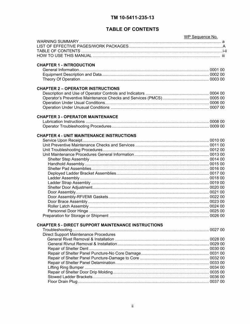
TABLE OF CONTENTS
WP Sequence No. WARNING SUMMARY.............................................................................................................................. a LIST OF EFFECTIVE PAGES/WORK PACKAGES...................................................................................ATABLE OF CONTENTS ............................................................................................................................. i-ii HOW TO USE THIS MANUAL ................................................................................................................. iii CHAPTER 1 - INTRODUCTION
General Information................................................................................................................... 0001 00 Equipment Description and Data............................................................................................... 0002 00 Theory Of Operation.................................................................................................................. 0003 00
CHAPTER 2 – OPERATOR INSTRUCTIONS
Description and Use of Operator Controls and Indicators ........................................................ 0004 00 Operator’s Preventive Maintenance Checks and Services (PMCS)......................................... 0005 00 Operation Under Usual Conditions............................................................................................ 0006 00 Operation Under Unusual Conditions ....................................................................................... 0007 00
CHAPTER 3 - OPERATOR MAINTENANCE
Lubrication Instructions ............................................................................................................. 0008 00 Operator Troubleshooting Procedures...................................................................................... 0009 00
CHAPTER 4 - UNIT MAINTENANCE INSTRUCTIONS
Service Upon Receipt................................................................................................................ 0010 00 Unit Preventive Maintenance Checks and Services ................................................................. 0011 00 Unit Troubleshooting Procedures.............................................................................................. 0012 00 Unit Maintenance Procedures General Information.................................................................. 0013 00
Shelter Step Assembly ......................................................................................................... 0014 00 Handhold Assembly.............................................................................................................. 0015 00 Shelter Pad Assemblies........................................................................................................ 0016 00 Deployed Ladder Bracket Assemblies.................................................................................. 0017 00 Ladder Assembly .................................................................................................................. 0018 00 Ladder Strap Assembly ........................................................................................................ 0019 00 Shelter Door Adjustment....................................................................................................... 0020 00 Door Assembly...................................................................................................................... 0021 00 Door Assembly-RFI/EMI Gaskets......................................................................................... 0022 00 Door Brace Assembly ........................................................................................................... 0023 00 Roller Latch Assembly .......................................................................................................... 0024 00 Personnel Door Hinge .......................................................................................................... 0025 00
Preparation for Storage or Shipment ........................................................................................ 0026 00
CHAPTER 5 - DIRECT SUPPORT MAINTENANCE INSTRUCTIONS Troubleshooting ......................................................................................................................... 0027 00 Direct Support Maintenance Procedures General Rivet Removal & Installation ................................................................................... 0028 00 General Rivnut Removal & Installation................................................................................. 0029 00 Repair of Shelter Dent .......................................................................................................... 0030 00 Repair of Shelter Panel Puncture-No Core Damage............................................................ 0031 00 Repair of Shelter Panel Puncture-Damage to Core ............................................................. 0032 00 Repair of Shelter Panel Delamination................................................................................... 0033 00 Lifting Ring Bumper .............................................................................................................. 0034 00 Repair of Shelter Door Drip Molding..................................................................................... 0035 00 Stowed Ladder Brackets....................................................................................................... 0036 00 Floor Drain Plug.................................................................................................................... 0037 00

TM 10-5411-235-13
iii
CHAPTER 5- DIRECT SUPPORT MAINTENANCE INSTRUCTIONS-Cont’d Installation of LMS Type 1 Shelter to HMMWV .................................................................... 0038 00 List of Manufactured Items ................................................................................................... 0039 00 CHAPTER 6 – SUPPORTING INFORMATION
References............................................................................................................................ 0040 00 General Maintenance Allocation Chart (MAC) Information ................................................. 0041 00 Maintenance Allocation Chart............................................................................................... 0042 00 Components of End Item (COEI) & Basic Issue Items (BII) Lists......................................... 0043 00 Expendable & Durable Items List ......................................................................................... 0044 00

TM 10-5411-235-13
iv
HOW TO USE THIS MANUAL
This manual explains how to operate and maintain the Lightweight Multi-Purpose Shelter (LMS). Take a few minutes to look through this manual. We’ve designed this manual to make it easier for you to find and perform the procedure you need.
1. If the LMS Type 1 Shelter needs repair and you know what is wrong with it, here is what you do:
a. Turn to the index and check for a paragraph on the component you want to remove and replace.
b. Turn to the paragraph. Under the paragraph title, you will find the tools, materials, and equipment condition needed to perform the procedure. If an equipment condition is needed to prepare the LMS Type 1 Shelter component for the removal procedure, it will be noted.
c. To remove defective components, follow the removal procedure.
d. To install the new component, perform the installation procedure. The LMS Type 1 Shelter should now be ready to operate.
e. Perform the applicable troubleshooting procedures to verify the repair of the LMS Type 1 Shelter component.
2. If the LMS Type 1 Shelter needs repair and you do not know what is wrong with it, go to the troubleshooting procedures. Identify the malfunction and locate it in the troubleshooting table. Then perform the tests/inspections and corrective actions in the order listed. If the malfunction is not listed in the troubleshooting table or is not corrected by the corrective action listed, notify the next higher level of maintenance.

CHAPTER 1
INTRODUCTION
FOR
LIGHTWEIGHT MULTIPURPOSE SHELTER (LMS)
LMS TYPE 1


TM 10-5411-235-13
GENERAL INFORMATION 0001 00
0001 00-1

TM 10-5411-235-13
GENERAL INFORMATION 0001 00
0001 00-2
SCOPE.
Type of Manual. This manual is an Operator’s, Unit, and Direct Support Maintenance Manual for the LMS Type 1 Shelter only.
Model Number and Equipment Name. The official equipment nomenclature is the Lightweight Multi-purpose Shelter (LMS), LMS Type 1. (Model S-788/G assigned to the LMS Type 1 Shelter.)
Purpose of Equipment. The LMS Type 1 Shelter is an enclosure assembly.
MAINTENANCE FORMS, RECORDS AND REPORTS. Department of the Army forms and procedures used for equipment maintenance will be those prescribed by DA PAM 738-750, The Army Maintenance Management System (TAMMS).
DESTRUCTION OF ARMY MATERIAL TO PREVENT ENEMY USE. For procedures and materials to destroy the NSN 5411-01-473-5051 enclosure, refer to TM 750-244-3, Procedures for Destruction of Equipment to Prevent Enemy Use.
PREPARATION FOR STORAGE AND SHIPMENT.
Definition.
For the placement of equipment in limited storage (less than 2 weeks) and reshipment, see 0026 00. The placement of equipment in administrative storage can be for short periods of time (6 months or less) when:
An organization lacks operating funds, personnel, other resources, and/or does not experience normal usage of its organic equipment.
Material which exceeds the capability of the owning organization to operate or maintain and must be maintained by that organization for contingency or other cogent reasons.
Installation or organization commanders may authorize the administrative storage of their material within the guidance furnished by MACOM Commanders and AR 750-1.
During the storage period, appropriate maintenance records will be kept.
SB 740-95-1, Storage Serviceability Standards for ACALA Material, will be followed to determine the required inspections for determining the serviceability of the LMS Type 1 Shelter in administrative storage.
Scope. The requirements specified herein are necessary to maintain the LMS Type 1 Shelter in administrative storage to achieve the maximum readiness.

TM 10-5411-235-13
GENERAL INFORMATION 0001 00
0001 00-3
General.
Equipment that is placed in administrative storage should be capable of being readied to perform the intended mission within a 24-hour period or as otherwise prescribed by the approving authority. Before equipment is placed in administrative storage, current maintenance services, shortcomings, and deficiencies should be corrected and all Modification Work Orders (MWOs) should be applied.
Report equipment in administrative storage in Material Readiness and Unit Readiness reports as prescribed for all reportable equipment. See AR 220-1.
NOTE
Touch-up painting will be in accordance with local SOP and requirements.
Records and reports to be maintained for equipment in administrative storage are the same as those prescribed by DA PAM 738-750 for equipment in use.
10% variance is acceptable on time running hours or mileage used to determine maintenance actions required.
Security. Instructions contained herein do not modify security procedures and requirements for classified or pilferable items. See AR 190-15 and AR 190-51.
Storage Site.
Select the best available site for administrative storage. Separate stored equipment from equipment in use. Boldly mark the area “Administrative Storage”.
Covered space is preferred. When covered space for all equipment to be stored is not available, select an open site and ensure that equipment is covered.
Open sites should be improved hardstand, if available. Unimproved sites should be firm, well drained, and kept free of excessive vegetation.
Storage Plan.
Store equipment to provide maximum protection from the elements and to provide access for inspection, maintenance, and exercising. Anticipate removal or deployment problems and take suitable precautions.

TM 10-5411-235-13
GENERAL INFORMATION 0001 00
0001 00-4
Take into account environmental conditions such as extreme heat or cold, high humidity, blowing sand/loose debris, soft ground, mud, heavy snows, or combinations thereof and take adequate precautions.
Establish a fire plan and provide for adequate fire fighting equipment and personnel.
Maintenance Services and Inspection. Prior to storage, perform the next scheduled major preventive maintenance service (monthly, quarterly or semi-annually).
Correction of Shortcomings and Deficiencies. Correct all shortcomings and deficiencies prior to storage or obtain a waiver from the approving authority.
Lubrication. Lubricate equipment in accordance with the applicable Lubrication Order or Technical Manual.
General Cleaning, Painting, and Preservation. Clean the equipment of dirt, grease or other contaminants in accordance with this manual.
Remove all rust and damaged paint by scraping, wire brushing, sanding, or buffing. Spot paint as required.
After cleaning and drying, immediately coat unpainted metal surfaces with an oil or grease, as appropriate.
Sunlight, heat, moisture (humidity) and dirt tend to accelerate deterioration. Close and secure all openings except those required for venting and draining. Seal openings to prevent the entry of rain, snow or dust. Place equipment and provide blocking or framing to allow ventilation and water drainage.
Tools and Mounted Equipment. Clean unplated surfaces of hand tools and accessories, and coat with lubricating oil (WP 0044, Table 1, Item 1).
Maintenance Services. After equipment has been placed in administrative storage, suspend all regularly scheduled maintenance services and inspect/exercise as specified herein. Do not reduce prescribed load list. See AR 735-5.
Inspection. Inspection will usually be visual and must consist of, at a minimum, a walk-around examination of all equipment to observe any deficiencies that may have occurred. Inspect equipment in open storage weekly, and equipment in covered storage monthly. Immediately,
TM 10-5411-235-13
GENERAL INFORMATION 0001 00
0001 00-5
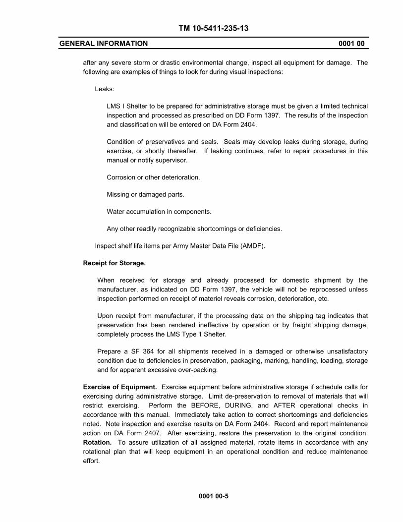
after any severe storm or drastic environmental change, inspect all equipment for damage. The following are examples of things to look for during visual inspections:
Leaks:
LMS I Shelter to be prepared for administrative storage must be given a limited technical inspection and processed as prescribed on DD Form 1397. The results of the inspection and classification will be entered on DA Form 2404.
Condition of preservatives and seals. Seals may develop leaks during storage, during exercise, or shortly thereafter. If leaking continues, refer to repair procedures in this manual or notify supervisor.
Corrosion or other deterioration.
Missing or damaged parts.
Water accumulation in components.
Any other readily recognizable shortcomings or deficiencies.
Inspect shelf life items per Army Master Data File (AMDF).
Receipt for Storage.
When received for storage and already processed for domestic shipment by the manufacturer, as indicated on DD Form 1397, the vehicle will not be reprocessed unless inspection performed on receipt of materiel reveals corrosion, deterioration, etc.
Upon receipt from manufacturer, if the processing data on the shipping tag indicates that preservation has been rendered ineffective by operation or by freight shipping damage, completely process the LMS Type 1 Shelter.
Prepare a SF 364 for all shipments received in a damaged or otherwise unsatisfactory condition due to deficiencies in preservation, packaging, marking, handling, loading, storage and for apparent excessive over-packing.
Exercise of Equipment. Exercise equipment before administrative storage if schedule calls for exercising during administrative storage. Limit de-preservation to removal of materials that will restrict exercising. Perform the BEFORE, DURING, and AFTER operational checks in accordance with this manual. Immediately take action to correct shortcomings and deficiencies noted. Note inspection and exercise results on DA Form 2404. Record and report maintenance action on DA Form 2407. After exercising, restore the preservation to the original condition. Rotation. To assure utilization of all assigned material, rotate items in accordance with any rotational plan that will keep equipment in an operational condition and reduce maintenance effort.

TM 10-5411-235-13
GENERAL INFORMATION 0001 00
0001 00-6
Removal From Administrative Storage. Remove preservative materials. Perform the next scheduled Preventive Maintenance Service and prepare the equipment for service as outlined in the Preventive Maintenance (WP 0005) and in accordance with instructions on DD Form 1397.
Servicing. Resume the maintenance service schedule in effect at the commencement of administrative storage as per DD Form 314. See DA PAM 738-750.
EQUIPMENT IMPROVEMENT RECOMMENDATIONS (EIRs). If your LMS enclosure needs improvement, let us know. Send in an EIR. You, the user, are the only one who can tell us what you do not like about your equipment. Let us know why, if you don’t like the design or performance. Put it on an SF 368, Product Quality Deficiency Report. Send it to us at: U.S. Army Soldier and Biological Chemical Command, ATTN: AMSSB-RIM-E (N), Kansas Street, Natick, MA 01760-5052. You may also send in your recommended changes via electronic mail directly to [email protected]. A reply will be furnished to you.
CORROSION PREVENTION AND CONTROL (CPC).
Corrosion Prevention and Control (CPC) of Army material is a continuing concern. It is important that any corrosion problems with this item be reported so that the problem can be corrected and improvements can be made to prevent the problem in future items.
While corrosion is typically associated with rusting of metals, it can also include deterioration of other materials such as rubber and plastic. Unusual cracking, softening, swelling or breaking of these materials may be indicative of a corrosion problem.
If a corrosion problem is identified, it can be reported using Standard Form 368, Quality Deficiency Report. Use of key words such as “corrosion”, “rust”, “deterioration” or “cracking” will assure that the information is identified as a CPC problem.
The form should be submitted in accordance with local standard operating procedures (SOP).

TM 10-5411-235-13
EQUIPMENT DESCRIPTION AND DATA 0002 00
0002 00-1
EQUIPMENT CHARACTERISTICS, CAPABILITIES AND FEATURES.
Physical Description. The LMS Type 1 Shelter consists of a structure of aluminum and steel.
Dimensions. The dimensions and weights of the LMS Type 1 Shelter.
Table 1. Physical Characteristics
Overall Length: 102 inches
Height: 67 inches
Width: 84 inches
Weight (Empty): 608 pounds maximum
Table 2. Equipment Data
Storage Space: 287 Cubic Feet
Cargo Capacity: 3300 pounds maximum
Weatherproofing. The LMS Type 1 enclosure structure is made of aluminum and steel and is treated for exterior rust prevention.
Shock and Vibration. The components of the LMS Type 1 Shelter are protected from shock and vibration damage during travel by the use of tie-down straps and brackets which secure the shelter in transit.
Functional Description.
Intended Use. The LMS Type 1 Shelter is designed to provide a work area with the space required to perform their assigned mission at remote locations.
Capabilities – The LMS Type 1 Shelter is a lightweight transportable shelter used to house various types of equipment as specified by the user. The shelter is normally mounted on a HMMWV. The shelter provides Radio Frequency/Electromagnetic Interference RFI/EMI shielding to protect user installed electronic equipment. The shield is a continuous metallic surface which maintains continuity around joints, door openings, entry panels and other possible sources of emissions leakage. The LMS Type 1 Shelter is designed for outdoor use in all weather conditions. There are no controls and/or indicators on the LMS Type 1 Shelter.
Limitations – The limitations of the LMS Type 1 Shelter are controlled by the user and the mission profile being expected.

TM 10-5411-235-13
EQUIPMENT DESCRIPTION AND DATA 0002 00
0002 00-2
LOCATION AND DESCRIPTION OF MAJOR COMPONENTS.
The ladder assembly is secured to the door during shelter transit and storage and is restrained by a strap below the door when the shelter is to be placed in operation. The drain plug provides an RFI/EMI seal for the floor drain during operation. The plug is loosened for air or rail transport. The step assembly located on the exterior wall, and the handhold located in the shelter roof provide easy access by personnel to the roof of the shelter. Four lifting rings are located at the top corners of the shelter provide attachment points for a sling assembly when the shelter is to be lifted on the HMMWV and/or transported.
Major shelter components are shown below.
HANDHOLD
LADDER ASSEMBLY
DOOR ASSEMBLY
DRAIN ASSEMBLY STEP ASSEMBLY
LIFTING RING ASSEMBLY

TM 10-5411-235-13
THEORY OF OPERATION 0003 00
0003 00-1/(2 Blank)
GENERAL. Operation of the LMS Type 1 Shelter is accomplished by mechanical interaction. The LMS Type 1 Shelter is designed to provide a work area with the space required to perform designated assigned mission. This shelter is normally mounted on a HMMWV for transportation. A ladder is mounted to the rear for access to the shelter when installed on a HMMWV. The fixed steps secured to the side of the shelter are for the operator to gain access to the roof. The personnel door allows the user access to the inside of the shelter. This shelter provides Radio Frequency/Electromagnetic Interference (RFI/EMI) shielding to protect user installed electronic equipment. A drain plug on the floor of the shelter allows the removal of excess moisture/water.


CHAPTER 2
OPERATOR INSTRUCTIONS
FOR
LIGHTWEIGHT MULTIPURPOSE SHELTER (LMS)
LMS TYPE 1


TM-10-5411-235-13
DESCRIPTION AND USE OF OPERATOR CONTROLS AND INDICATORS 0004 00
0004 00-1/(2 Blank)
INTRODUCTION. This section describes, locates and illustrates the controls/mechanical features of the LMS Type 1 Shelter used to operate and access the shelter.
FUNCTIONS OF MECHANICAL DEVICES
Personnel Door – Used to enter and exit the shelter during normal operation.
Roller Latch Assembly – Used to secure the shelter door in transit/storage and during normal operation.
Personnel Ladder –Used to access the shelter when the shelter is installed onto the HMMWV.
Drain Plug – Used to allow the removal of excess moisture/water from the shelter.
Steps – Used by operator to gain access to shelter roof.
Roof Handhold – Used to assist the operator when accessing shelter roof.
END OF WORK PACKAGE


TM-10-5411-235-13
OPERATOR’S PREVENTIVE MAINTENANCE CHECKS AND SERVICES 0005 00
0005 00-1
INTRODUCTION.
General.
Before You Operate. Always be aware of the cautions and warnings. Perform your BEFORE PMCS.
While You Operate. Always be aware of the cautions and warnings. Perform your DURING PMCS.
After You Operate. Always be aware of the cautions and warnings. Always be sure to perform your AFTER Operations PMCS.
If Your Equipment Fails To Operate. If your equipment does not perform as required, Refer to Chapter 3, 0009 00, under Troubleshooting for possible faults. Record any malfunctions or failures on DA Form 2404, or refer to DA PAM 738-750.

TM-10-5411-235-13
OPERATOR’S PREVENTIVE MAINTENANCE CHECKS AND SERVICES 0005 00
0005 00-2
NOTE
Within designated intervals, these checks are to be performed in the order listed.
BEFORE OPERATION
* 1) Inspect the exterior of the shelter for evidence of damage to shelter walls, roof, or floor.
2) Inspect the ladder to ensure it is secure. * 3) Inspect the door and locking mechanism for proper operation and no
loose or missing hardware.
4) Inspect the shelter mounting hardware to the HMMWV for loose or missing hardware.
5) Inspect the interior for evidence of excess moisture/water.
DURING OPERATION
1) Periodically inspect the shelter mounting hardware for loose or missing hardware.
2) Periodically inspect the shelter walls for damage.
AFTER OPERATION * 1) Inspect the exterior of the shelter for evidence of damage to the shelter walls or roof.
2) Inspect the interior for evidence of excessive moisture.
NOTE Asterisks denote that the shelter is not mission ready if the condition outlined exists. Report these conditions to your supervisor/organizational maintenance and complete a Form 2404 and/or other maintenance forms required by your command.

TM-10-5411-235-13
OPERATOR’S PREVENTIVE MAINTENANCE CHECKS AND SERVICES 0005 00
0005 00-3
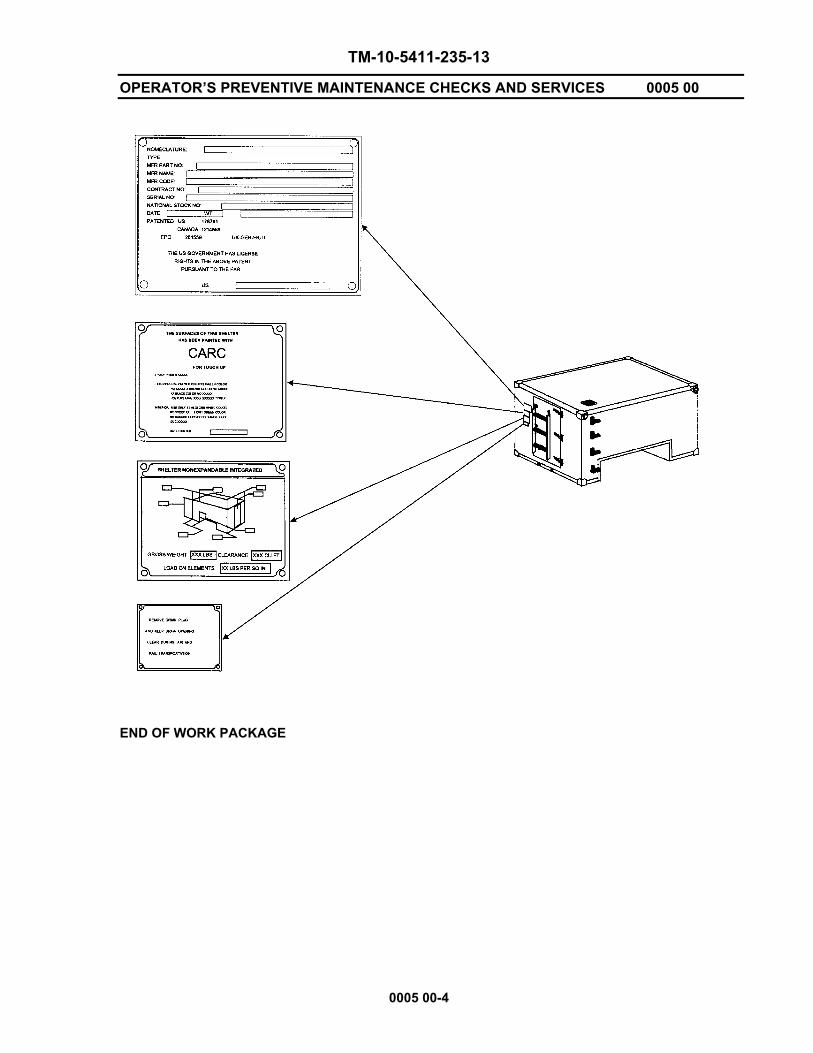
Table 1. Decals and Instruction Plates
INDEX ITEM DESCRIPTION 1 IDENTIFICATION PLATE Provides pertinent shelter information including nomenclature, type, serial number and other manufacturer data. 2 PAINT INSTRUCTION PLATE The surfaces of this shelter have been painted with CARC. For touch-up, Epoxy
primer IAW MIL-P-53022. Exterior – Use only lusterless green color
no. 34094, brown, color no. 30051 and black, color no. 37030, polyurethane IAW
MIL-C-46168, Type II Interior – Use only semi-gloss white, color no. 27875 and light green, color no. 24533, epoxy polyamide IAW MIL-C-22750 3 AIRCRAFT LOADING Provides aircraft loading data to include DATA PLATE physical dimensions and shelter weight. NOTE The weight annotated reflects the shelter weight empty. 4 AIRBORNE INSTRUCTIONS Outlines what equipment is to be removed during air/rail transport of the shelter.
TM-10-5411-235-13
OPERATOR’S PREVENTIVE MAINTENANCE CHECKS AND SERVICES 0005 00
0005 00-4
END OF WORK PACKAGE

TM-10-5411-235-13
OPERATION UNDER USUAL CONDITIONS 0006 00
0006 00-1/(2 Blank)
GENERAL. The instructions in this section are published for information and guidance of the personnel responsible for the operation of the LMS enclosure. It is essential that the operator know how to perform every operation of which the LMS enclosure is capable. This section gives instructions on enclosure components and coordinating the basic motions to perform the specific tasks for which the equipment is designed. Since nearly every job presents a different operating situation, the operator may have to vary the given procedure to fit the individual job.
OPERATION UNDER USUAL CONDITIONS
There are no special requirements associated with operating the shelter under usual conditions.
END OF WORK PACKAGE

TM-10-5411-235-13
OPERATION UNDER UNUSUAL CONDITIONS 0007 00
0007 00-1/(2 Blank)
General. Operation of the LMS Type 1 Shelter under unusual conditions pertains to weather and environmental conditions. Unusual conditions are defined as extreme heat or cold, sandy areas, dusty areas, salt water areas, high altitudes or similar conditions not normally encountered.
Operation. Operation of the LMS Type 1 enclosure under unusual conditions requires inspection of selected components based on the environmental and unusual conditions. The differences are in the type and frequency of lubrication, preventive maintenance and cleaning. The same preventive maintenance concepts apply to operation of the LMS Type 1 Shelter under unusual conditions and usual conditions. The difference is in the frequency of performance. Under unusual conditions, the various checks and procedures must be performed once a week to ensure optimum performance of equipment.
Operation in Extreme Cold.
Inspect seals and gaskets for possible damage.
Operation in Salt Water Areas.
General. Wipe the exposed surfaces of the LMS enclosure interior and exterior, as well as component surfaces, with clean, fresh water. Be careful not to contaminate the fuel system or damage the electrical system with water.
Protection. Remove all rust and corrosion immediately. Coat exposed metal surfaces with corrosion prevention compound material and apply primer coating (WP 0044, Table 1, Item 33), or lubricating oil (WP 0044, Table 1, Item 34,) as required.
Heat and High Humidity
General. Lubricate all mechanically operated linkages to avoid rusting/seizure.
Protection. Lubricate with lubricating oil (WP 0044, Table 1, Item 34.)
END OF WORK PACKAGE


CHAPTER 3
OPERATOR MAINTENANCE
FOR
LIGHTWEIGHT MULTIPURPOSE SHELTER (LMS)
LMS TYPE 1

TM 10-5411-235-13
LUBRICATION INSTRUCTIONS 0008 00
0008 00-1
GENERAL. No separate Lubrication Order (LO) is available for the LMS Type 1 Shelter; therefore, lubrication instructions contained in this section are mandatory.
LUBRICATION INSTRUCTIONS.
General. Keep all lubricants in closed containers and store in a clean dry place away from external heat. Allow no dust, dirt or other foreign matter to mix with the lubricants. Keep all lubrication equipment clean.
Cleaning. Wipe lubrication points and surrounding areas until free of dirt. Clean lubrication points and surrounding areas before and after lubrication. Clean up all spilled lubricants to prevent accumulation of dirt and foreign matter.
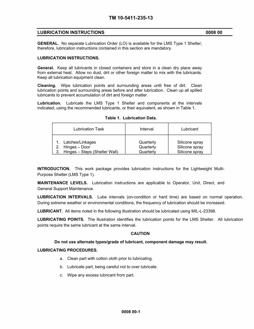
Lubrication. Lubricate the LMS Type 1 Shelter and components at the intervals indicated, using the recommended lubricants, or their equivalent, as shown in Table 1.
Table 1. Lubrication Data.
Lubrication Task Interval Lubricant
1. Latches/Linkages 2. Hinges – Door 3. Hinges – Steps (Shelter Wall)
Quarterly Quarterly Quarterly
Silicone spray Silicone spray Silicone spray
INTRODUCTION. This work package provides lubrication instructions for the Lightweight Multi-Purpose Shelter (LMS Type 1).
MAINTENANCE LEVELS. Lubrication instructions are applicable to Operator, Unit, Direct, and General Support Maintenance.
LUBRICATION INTERVALS. Lube intervals (on-condition or hard time) are based on normal operation. During extreme weather or environmental conditions, the frequency of lubrication should be increased.
LUBRICANT. All items noted in the following illustration should be lubricated using MIL-L-23398.
LUBRICATING POINTS. The illustration identifies the lubrication points for the LMS Shelter. All lubrication points require the same lubricant at the same interval.
CAUTION
Do not use alternate types/grade of lubricant, component damage may result.
LUBRICATING PROCEDURES.
a. Clean part with cotton cloth prior to lubricating.
b. Lubricate part, being careful not to over lubricate.
c. Wipe any excess lubricant from part.

TM 10-5411-235-13
LUBRICATION INSTRUCTIONS 0008 00
0008 00-2
Table 1. Lubricant Table for LMS Type 1 Shelter
Air Cure Test Temperature Range Lubricant Capacity Interval Man-hour 25° + 2°C to 77 + 3°F MIL-L-23398 as required Quarterly 1 Hour 50% Rel. Hum. (S-179) Lube Pt. Description A Handhold B Step Assys C Lift Rings D Door Hinges E Roller Latch Assy F Door Brace
AB
C
C
C
D
F
E
END OF WORK PACKAGE
TM 10-5411-235-13
OPERATOR TROUBLESHOOTING PROCEDURES 0009 00
0009 00-1
INTRODUCTORY INFORMATION.
The troubleshooting table lists the common malfunctions that you may find during the operation or maintenance of the LMS Type 1 Shelter or components. You should perform the tests/inspections and corrective actions in the order listed.
This manual cannot list all possible malfunctions that may occur, nor all test or inspections and corrective actions. If a malfunction is not listed or is not corrected by the listed corrective actions, notify your supervisor.
SYMPTOM INDEX.
MALFUNCTION/SYMPTOM TROUBLSHOOTING PROCEDURE MOUNTING Excessive Noise or Vibration 0009 00-2 Damage to Shelter Floor 0009 00-2 SEALS/GASKETS Excessive Moisture in Shelter 0009 00-2 Excessive Moisture/Air entering Shelter 0009 00-2 DOOR Personnel Door Binding or Fails to Close Securely 0009 00-2 SHELTER WALLS, ROOF, FLOOR Shelter Structure Damaged 0009 00-2
WARNING
Be sure to read all warnings in front of the manual before troubleshooting.

TM-10-5411-235-13
OPERATOR TROUBLESHOOTING PROCEDURES 0009 00
0009 00-2
Table 2. Operator Troubleshooting Procedures
INITIAL SETUP: Maintenance Level Materials/Parts Operator
MALFUNCTION TEST OR INSPECTION CORRECTIVE ACTION
1. Excessive Noise and
Vibration 2. Excessive Air/Moisture
in Shelter 3. Personnel Door
Binding 4. Personnel Door Fails
to Lock 5. Personnel Door Fails
to Close Tightly 6. Damage to Shelter
Floor
1. Inspect the mounting hardware
securing the LMS I to HMMWV 1. Inspect exterior & interior walls for
damage 2. Inspect to ensure drain plug is
installed 1. Inspection of door jamb for
evidence of obstruction or dirt 2. Inspect for broken door hinge/or
loose or missing hardware 1. Inspect Roller Latch Assembly for
missing hardware or bent control rods
2. Roller Latch Assembly fails to
completely secure door 1. Inspect EMI and weather gasket
for damage 1. Inspect for proper meeting of
shelter walls and floor and/or missing hardware
1. Secure/Replace missing
hardware 1. Notify Unit Maintenance 2. Re-install drain plug. See 0037 00-1 1. Clean door jamb of
obstruction 2. Replace door hinge. Notify
Supervisor/Unit Maintenance
1. Notify Unit Maintenance if
damaged Roller Latch Assembly
2. Notify Unit Maintenance of
door shimming requirement 1. Notify Unit Maintenance of
damaged seals 1. Notify Unit Maintenance
END OF WORK PACKAGE

CHAPTER 4
UNIT MAINTENANCE INSTRUCTIONS
FOR
LIGHTWEIGHT MULTIPURPOSE SHELTER (LMS)
LMS TYPE 1


TM-10-5411-235-13
SERVICE UPON RECEIPT 0010 00
0010 00-1/(2 Blank)
SERVICE UPON RECEIPT OF EQUIPMENT.
Inspection. Inspect shelter for damage incurred during shipment. If the shelter has been damaged, report the damage in accordance with the instructions in the Warranty Technical Bulletin, TB 10-5411-235-13. If the shelter is crated or pallet mounted, refer to the end item technical manual for unpacking instructions. If the shelter is to be loaded onto a new HMMWV, perform the following:
NOTE
• For shelters to be replaced or moved from one vehicle to another and for any component of the installation mounting kit which requires maintenance, perform only the steps which are applicable.
• Prior to performing the following procedures, remove Shelter-to-Vehicle Mounting Kit and inventory per WP 0043, Table 2.
• For LMS Type 1 Shelter Installation Instructions onto HMMWV, see WP 0038.
Check for any loose or missing hardware. Tighten or replace as needed.
Check that all LMS enclosure components are securely tied down. Tighten securing straps as needed.
Lubrication. Perform initial lubrication on the LMS enclosure equipment/components as outlined in WP 0008 00-1, Table 1.
Completeness of Equipment. Ensure that all of the authorized components, materials and accessories are present upon receipt of the LMS enclosure.
END OF WORK PACKAGE

TM-10-5411-235-13
UNIT PREVENTIVE MAINTENANCE CHECKS AND SERVICES (PMCS) 0011 00
0011 00-1
INTRODUCTION.
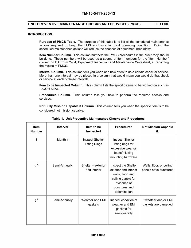
Purpose of PMCS Table. The purpose of this table is to list all the scheduled maintenance actions required to keep the LMS enclosure in good operating condition. Doing the scheduled maintenance actions will reduce the chances of equipment breakdown.
Item Number Column. This column numbers the PMCS procedures in the order they should be done. These numbers will be used as a source of item numbers for the “Item Number” column on DA Form 2404, Equipment Inspection and Maintenance Worksheet, in recording the results of PMCS.
Interval Column. This column tells you when and how often to do a certain check or service. More than one interval may be placed in a column that would mean you would do that check or service at each of these intervals.
Item to be Inspected Column. This column lists the specific items to be worked on such as “DOOR SEAL”.
Procedures Column. This column tells you how to perform the required checks and services.
Not Fully Mission Capable If Column. This column tells you when the specific item is to be considered not mission capable.
Table 1. Unit Preventive Maintenance Checks and Procedures
Item Number
Interval Item to be Inspected
Procedures Not Mission Capable if:
1 Monthly Inspect Shelter Lifting Rings
Inspect Shelter lifting rings for
excessive wear or loose/missing
mounting hardware
2* Semi-Annually Shelter – exterior and interior
Inspect the Shelter exterior and interior
walls, floor, and ceiling panels for
evidence of punctures and delamination
Walls, floor, or ceiling panels have punctures
3* Semi-Annually Weather and EMI gaskets
Inspect condition of weather and EMI
gaskets for serviceability
If weather and/or EMI gaskets are damaged

TM-10-5411-235-13
UNIT PREVENTIVE MAINTENANCE CHECKS AND SERVICES (PMCS) 0011 00
0011 00-2
4 Semi-Annually Lifting Ring Bumpers
Inspect lifting ring bumpers for loose
or missing hardware
5 Semi-Annually Shelter Pads Inspect shelter pads for corrosion and loose/missing
hardware
6 Semi-Annually Shelter Steps Inspect shelter steps for corrosion or loose/missing
hardware
7 Semi-Annually Shelter Roof Handle
Inspect shelter roof handle to ensure it
is securely fastened
8 Semi-Annually Ladder Assembly Inspect ladder assembly for corrosion and
defective/broken welds.
9* Semi-Annually Ladder Strap Assembly
Inspect Strap Assembly for torn, broken/defective or
missing parts.
10 Semi-Annually Drain Plug Inspect shelter drain plug and seal
for serviceability
If missing or damaged
NOTE Asterisks denote that the shelter is not mission ready if the condition outlined exists. Report these conditions to your supervisor/organizational maintenance and complete a Form 2404 and/or other maintenance forms required by your command.
END OF WORK PACKAGE

TM-10-5411-235-13
UNIT TROUBLESHOOTING PROCEDURES 0012 00
0012 00-1
INTRODUCTORY INFORMATION.
The following table lists common malfunctions that might be found during the maintenance of the LMS Type 1 Shelter and components. Tests/inspections and corrective actions should be performed in the order listed.
This manual cannot list all the malfunctions that may occur, nor all tests or inspections and corrective actions. If a malfunction is not listed or is not corrected by the listed corrective actions, notify your supervisor.
Table 2. Symptom Index.
Symptom Page
1. Loss of personnel door locking capability. 0012 00-2
2. Exterior steps seized. 0012 00-2
3. Exterior wall damaged. 0012 00-2
TM-10-5411-235-13
UNIT TROUBLESHOOTING PROCEDURES 0012 00
0012 00-2
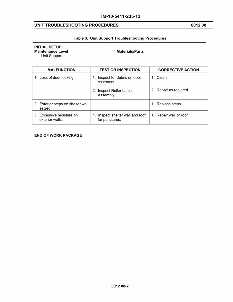
Table 3. Unit Support Troubleshooting Procedures INITIAL SETUP: Maintenance Level Materials/Parts Unit Support
MALFUNCTION TEST OR INSPECTION CORRECTIVE ACTION
1. Loss of door locking. 1. Inspect for debris on door casement.
2. Inspect Roller Latch
Assembly.
1. Clean.
2. Repair as required.
2. Exterior steps on shelter wall seized.
1. Replace steps.
3. Excessive moisture on exterior walls.
1. Inspect shelter wall and roof for punctures.
1. Repair wall or roof.
END OF WORK PACKAGE

TM-10-5411-235-13
UNIT MAINTENANCE PROCEDURES GENERAL INFORMATION 0013 00
0013 00-1/(2 Blank)
GENERAL. Unit level maintenance and repair will primarily involve shelter exteriors or easily accessible interior areas. Do not operate electronic equipment when floors, ceilings, or walls show evidence of water intrusion. Notify your supervisor if any of the following conditions exist:
a. Structural. Panel damage spans a structural member. b. Wall, Ceiling, and Floor Panels. Replacement of an entire wall, ceiling, or floor is
required.
c. Unauthorized Removal of Equipment. Extensive removal of equipment is necessary that is beyond the capability of using the LMS Type 1 Shelter.
d. Welding. Welding is required.
e. Distortion of Panels. Damage to a structural member is severe enough to cause
distortion of a wall, especially an edge or corner area.
f. Non-visible Damage Assessment. Lift fittings or corner castings are damaged severely enough to indicate possible damage to the underlying structure member.
SPECIAL TOOLS, TMDE, AND SUPPORT EQUIPMENT. No special tools or test equipment are required to repair the shelter.
REPAIR PARTS. Refer to the Repair Parts, Special Tools List (RPSTL) TM 10-5411-235-23P for the authorized repair parts used by Unit Maintenance in the repair of the shelter. END OF WORK PACKAGE


TM-10-5411-235-13
SHELTER STEP ASSEMBLY 0014 00
0014 00-1/(2 Blank)
THIS WORK PACKAGE COVERS: Replace INITIAL SETUP: Maintenance Level Unit
Tools: General Mechanics Tool Kit ( WP 0042, Table 2, Item 1) Materials/Parts: Step Assembly Lockwasher Screw REPLACE REMOVE
1. Remove two screws (1) and lock washers (2) securing step (3) to shelter.
INSTALL 1. Locate step (3) on shelter. 2. Install two screws (1) and two lockwashers (2) to secure step (3) to shelter wall.
1
23 END OF WORK PACKAGE

TM 10-5411-235-13
HANDHOLD ASSEMBLY 0015 00
0015 00-1
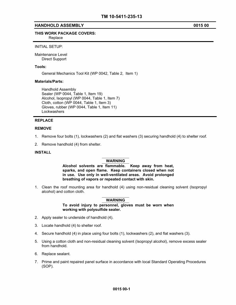
THIS WORK PACKAGE COVERS: Replace INITIAL SETUP: Maintenance Level Direct Support
Tools: General Mechanics Tool Kit (WP 0042, Table 2, Item 1) Materials/Parts: Handhold Assembly Sealer (WP 0044, Table 1, Item 19) Alcohol, Isopropyl (WP 0044, Table 1, Item 7) Cloth, cotton (WP 0044, Table 1, Item 3) Gloves, rubber (WP 0044, Table 1, Item 11) Lockwashers REPLACE REMOVE 1. Remove four bolts (1), lockwashers (2) and flat washers (3) securing handhold (4) to shelter roof. 2. Remove handhold (4) from shelter. INSTALL
WARNING Alcohol solvents are flammable. Keep away from heat, sparks, and open flame. Keep containers closed when not in use. Use only in well-ventilated areas. Avoid prolonged breathing of vapors or repeated contact with skin.
1. Clean the roof mounting area for handhold (4) using non-residual cleaning solvent (Isopropyl
alcohol) and cotton cloth.
WARNING To avoid injury to personnel, gloves must be worn when working with polysulfide sealer.
2. Apply sealer to underside of handhold (4).
3. Locate handhold (4) to shelter roof.
4. Secure handhold (4) in place using four bolts (1), lockwashers (2), and flat washers (3).
5. Using a cotton cloth and non-residual cleaning solvent (Isopropyl alcohol), remove excess sealer from handhold.
6. Replace sealant. 7. Prime and paint repaired panel surface in accordance with local Standard Operating Procedures
(SOP).

TM-10-5411-235-13
HANDHOLD ASSEMBLY 0015 00
0015 00-2
1
2
3
4
END OF WORK PACKAGE
TM-10-5411-235-13
SHELTER PAD ASSEMBLIES 0016 00
0016 00-1
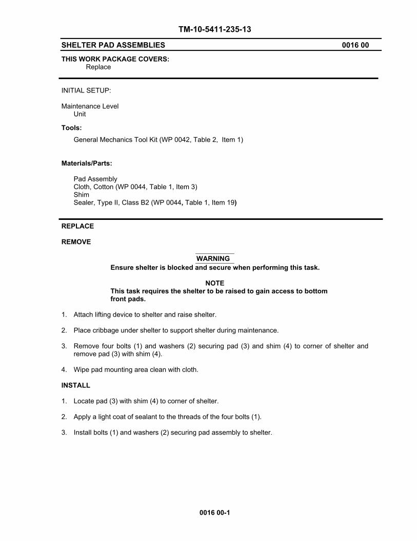
THIS WORK PACKAGE COVERS: Replace INITIAL SETUP: Maintenance Level Unit
Tools: General Mechanics Tool Kit (WP 0042, Table 2, Item 1) Materials/Parts: Pad Assembly Cloth, Cotton (WP 0044, Table 1, Item 3) Shim Sealer, Type II, Class B2 (WP 0044, Table 1, Item 19) REPLACE REMOVE
WARNING Ensure shelter is blocked and secure when performing this task.
NOTE This task requires the shelter to be raised to gain access to bottom front pads.
1. Attach lifting device to shelter and raise shelter.
2. Place cribbage under shelter to support shelter during maintenance.
3. Remove four bolts (1) and washers (2) securing pad (3) and shim (4) to corner of shelter and
remove pad (3) with shim (4).
4. Wipe pad mounting area clean with cloth. INSTALL 1. Locate pad (3) with shim (4) to corner of shelter.
2. Apply a light coat of sealant to the threads of the four bolts (1).
3. Install bolts (1) and washers (2) securing pad assembly to shelter.

TM-10-5411-235-13
SHELTER PAD ASSEMBLIES 0016 00
0016 00-2
4
3
2
1
END OF WORK PACKAGE

TM-10-5411-235-13
DEPLOYED LADDER BRACKET ASSEMBLIES 0017 00
0017 00-1
THIS WORK PACKAGE COVERS: Replace INITIAL SETUP: Maintenance Level Unit
Tools: General Mechanics Tool Kit (WP 0042, Table 2, Item 1) Materials/Parts: Ladder Bracket – Deployed (roadside) Ladder Bracket – Deployed (curbside) REPLACE REMOVE 1. Remove two screws (1) and washers (2) securing curbside bracket (3) to shelter.
2. Remove two screws (1) and washers (2) securing roadside bracket (4) to shelter. INSTALL 1. Locate roadside deployed bracket (4) to shelter and secure using two screws (1) and washers (2).
2. Locate curbside deployed bracket (3) to shelter and secure using two screws (1) and washers (2).

TM-10-5411-235-13
DEPLOYED LADDER BRACKET ASSEMBLIES 0017 00
0017 00-2
4
1 2 3 END OF WORK PACKAGE

TM-10-5411-235-13
LADDER ASSEMBLY 0018 00
0018 00-1/(2 Blank)
THIS WORK PACKAGE COVERS: Replace INITIAL SETUP: Maintenance Level Unit
Tools: None Materials/Parts: Ladder REPLACE 1. Completely loosen retaining strap (1) securing the ladder (2) to the door (3) and lift ladder (2) off
of storage brackets (4).
2. Place new ladder (2) on stowage brackets (4) and secure with retaining strap (1).
1
2
3 4
END OF WORK PACKAGE


TM-10-5411-235-13
LADDER STRAP ASSEMBLY 0019 00
0019 00-1
THIS WORK PACKAGE COVERS: Replace INITIAL SETUP: Maintenance Level Unit
Tools: General Mechanics Tool Kit (WP 0042, Table 2, Item 1) Materials/Parts: Strap
REMOVAL 1. At the shelter door, completely loosen strap (2). Remove ladder. 2. Remove the screw (4) and two washers (1 & 3) securing the strap to the door. INSTALLATION 1. Locate strap (2) and secure the strap to the door using two washers (1 & 3) and a screw (4). 2. Secure and tighten.
3. Place ladder on door and secure with strap.

TM-10-5411-235-13
LADDER STRAP ASSEMBLY 0019 00
0019 00-2
12
3
4
END OF WORK PACKAGE

TM 10-5411-235-13
SHELTER DOOR ADJUSTMENT 0020 00
0020 00-1
THIS WORK PACKAGE COVERS: Test, Adjustment INITIAL SETUP: Maintenance Level Unit
Tools: General Mechanics Tool Kit (WP 0042, Table 2, Item 1) Materials/Parts: Shim (WP 0044, Table 1, Item 23) TEST 1. Place a single piece of paper 0.005 inches thick by 2 ½ inches wide (e.g., a dollar bill) between
the door silicone weather gasket and its bearing surface. 2. Close and latch the door and withdraw the paper. Do this at the top, middle, and bottom sections
of the door. If there is resistance to the withdrawal at each of the test points, sufficient seal pressure exists and no adjustments are necessary. If there is no resistance at the hinged site, notify your supervisor. If there is no resistance at the roller latch side, increase the gasket compression by adding shims as follows:
ADJUSTMENT 1. Open door and remove Roller Latch Assembly (WP 0024). 2. Remove two bolts (1) and lockwashers (2) securing striker plate (3) at the location requiring
adjustment. 3. Insert approximately 0.032” aluminum alloy shim(s) (4) between striker plate (3) and door panel,
to a maximum thickness of 0.096”. 4. Locate striker plate (3) with added shim(s) (4) to door and secure with two bolts (1) and
lockwashers (2). 5. Retest the door assembly for proper closure pressure and repeat adjustment procedure as
necessary.

TM 10-5411-235-13
SHELTER DOOR ADJUSTMENT 0020 00
0020 00-2
1
2
34
1
1
2
2
3
3
4
4
END OF WORK PACKAGE

TM 10-5411-235-13
DOOR ASSEMBLY 0021 00
0021 00-1
THIS WORK PACKAGE COVERS: Replace, Test, and Adjustment INITIAL SETUP: Maintenance Level Personnel Required: (2) Unit
Tools: General Mechanics Tool Kit (WP 0042, Table 2, Item 1) Materials/Parts: Door Assembly Lockwasher Lockwasher Cotter Pin (WP 0044, Table 1, Item 22) Shim (WP 0044, Table 1, Item 23) Sealer (WP 0044, Table 1, Item 19) Equipment Condition: Roller Latch Assembly removed (WP 0024) REPLACE
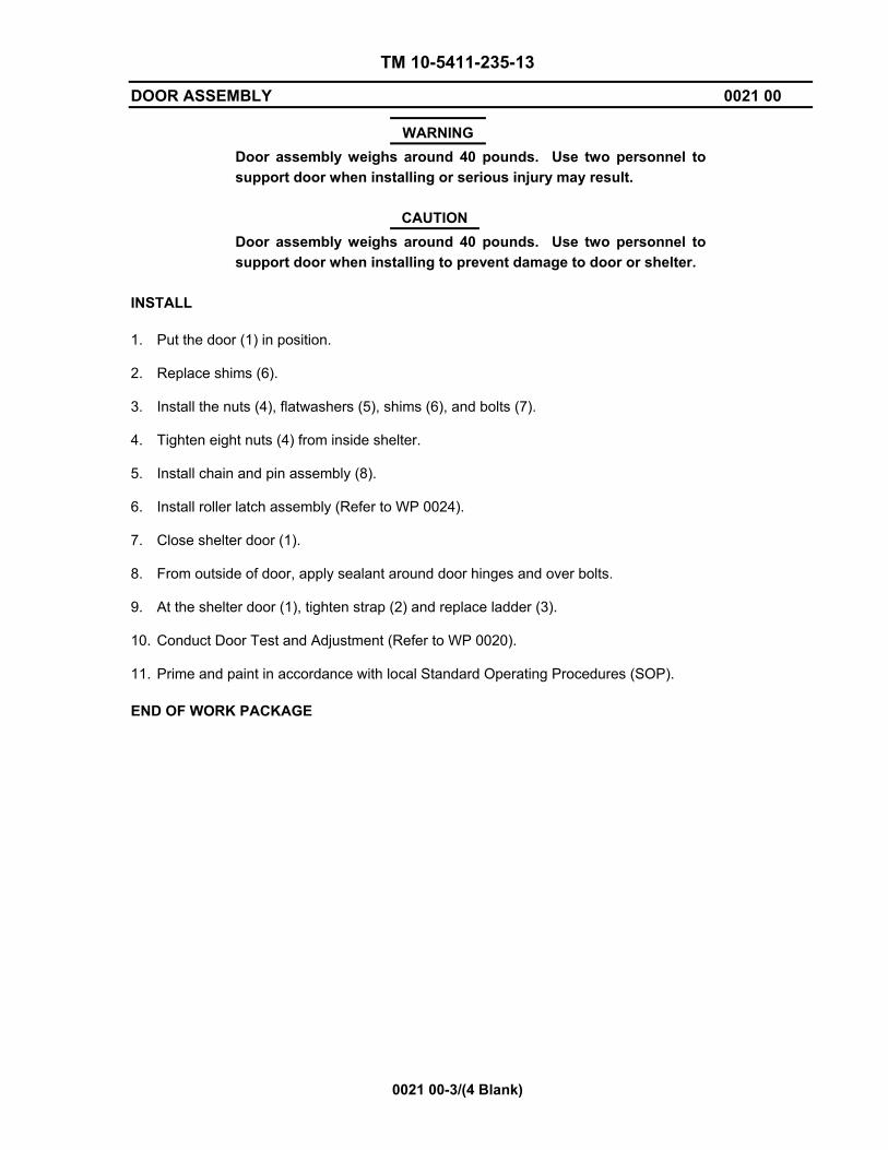
WARNING Door assembly weighs around 40 pounds. Use two personnel to support door during removal or serious injury may result.
CAUTION
Door assembly weighs around 40 pounds. Use two personnel to support door during removal to prevent damage to door or shelter.
REMOVE 1. At the shelter door (1), loosen strap (2) and remove ladder (3).
2. Open shelter door (1).
3. Remove chain and pin assembly (8). 4. From outside of door, remove sealant from around door hinges. 5. Loosen eight nuts (4) inside of door. With nuts still on the end of the bolts, tap nut lightly with
hammer to loosen bolt from sealant. 6. Remove nuts (4) and flatwashers (5) from bolts (7), push bolts through door. Retain nuts, bolts,
and flatwashers. 7. Remove and retain shims (6). 8. Remove the door (1).

TM 10-5411-235-13
DOOR ASSEMBLY 0021 00
0021 00-2
2 3
4 56
7
8
1
TM 10-5411-235-13
DOOR ASSEMBLY 0021 00
0021 00-3/(4 Blank)
WARNING Door assembly weighs around 40 pounds. Use two personnel to support door when installing or serious injury may result.
CAUTION
Door assembly weighs around 40 pounds. Use two personnel to support door when installing to prevent damage to door or shelter.
INSTALL 1. Put the door (1) in position. 2. Replace shims (6). 3. Install the nuts (4), flatwashers (5), shims (6), and bolts (7). 4. Tighten eight nuts (4) from inside shelter. 5. Install chain and pin assembly (8). 6. Install roller latch assembly (Refer to WP 0024). 7. Close shelter door (1). 8. From outside of door, apply sealant around door hinges and over bolts. 9. At the shelter door (1), tighten strap (2) and replace ladder (3). 10. Conduct Door Test and Adjustment (Refer to WP 0020). 11. Prime and paint in accordance with local Standard Operating Procedures (SOP). END OF WORK PACKAGE

TM 10-5411-235-13
DOOR ASSEMBLY - RFI/EMI GASKETS 0022 00
0022 00-1
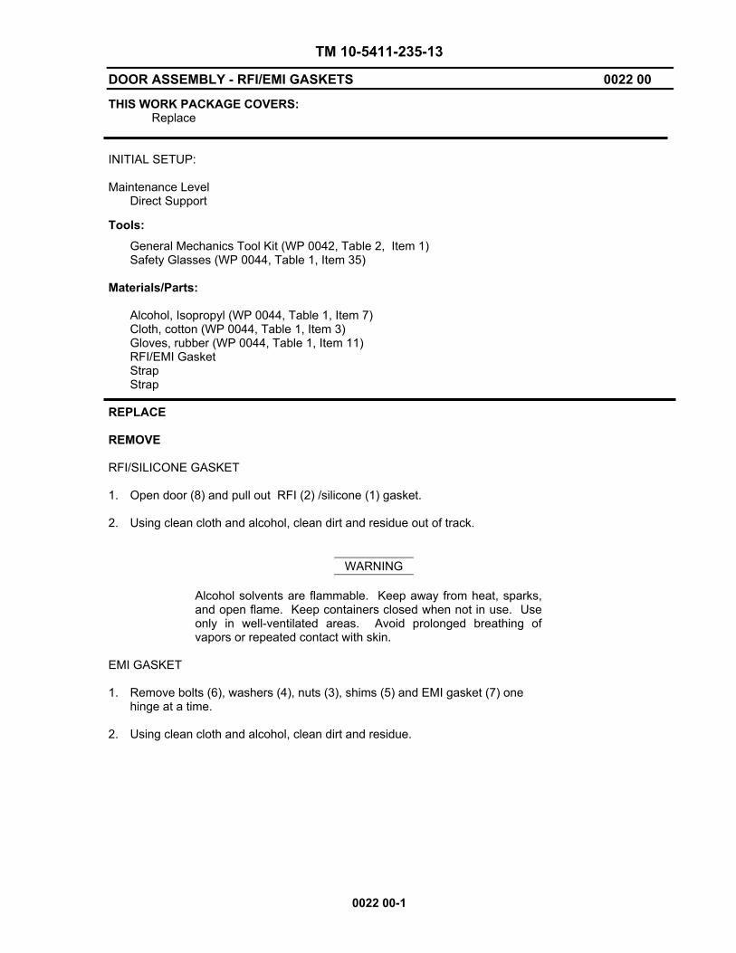
THIS WORK PACKAGE COVERS: Replace INITIAL SETUP: Maintenance Level Direct Support
Tools: General Mechanics Tool Kit (WP 0042, Table 2, Item 1) Safety Glasses (WP 0044, Table 1, Item 35) Materials/Parts: Alcohol, Isopropyl (WP 0044, Table 1, Item 7) Cloth, cotton (WP 0044, Table 1, Item 3) Gloves, rubber (WP 0044, Table 1, Item 11) RFI/EMI Gasket Strap Strap REPLACE REMOVE RFI/SILICONE GASKET 1. Open door (8) and pull out RFI (2) /silicone (1) gasket. 2. Using clean cloth and alcohol, clean dirt and residue out of track.
WARNING
Alcohol solvents are flammable. Keep away from heat, sparks, and open flame. Keep containers closed when not in use. Use only in well-ventilated areas. Avoid prolonged breathing of vapors or repeated contact with skin.
EMI GASKET 1. Remove bolts (6), washers (4), nuts (3), shims (5) and EMI gasket (7) one
hinge at a time.
2. Using clean cloth and alcohol, clean dirt and residue.

TM 10-5411-235-13
DOOR ASSEMBLY - RFI/EMI GASKET 0022 00
0022 00-2
1
3
4
56
7 8
1
2
6
3
5
7
4
8
TM 10-5411-235-13
DOOR ASSEMBLY-RFI/EMI GASKETS 0022 00
0022 00-3/(4 Blank)
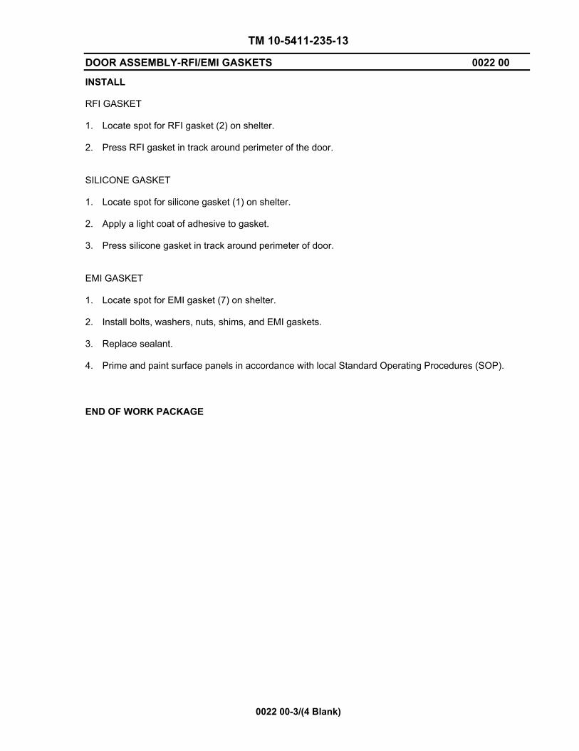
INSTALL RFI GASKET 1. Locate spot for RFI gasket (2) on shelter.
2. Press RFI gasket in track around perimeter of the door. SILICONE GASKET 1. Locate spot for silicone gasket (1) on shelter.
2. Apply a light coat of adhesive to gasket.
3. Press silicone gasket in track around perimeter of door. EMI GASKET 1. Locate spot for EMI gasket (7) on shelter.
2. Install bolts, washers, nuts, shims, and EMI gaskets. 3. Replace sealant. 4. Prime and paint surface panels in accordance with local Standard Operating Procedures (SOP).
END OF WORK PACKAGE


TM 10-5411-235-13
DOOR BRACE ASSEMBLY 0023 00
0023 00-1
THIS WORK PACKAGE COVERS: Replace INITIAL SETUP: Maintenance Level Unit
Tools: General Mechanics Tool Kit ( WP 0042, Table 2, Item 1) Materials/Parts: Door Brace Assembly Cotter Pin (WP 0044, Table 1, Item 22) Lockwasher Lockwasher REPLACE REMOVE ANGLE DOOR STOP (10) 1. Remove six screws (9) and shims (8). LOWER DOOR BRACE ASSEMBLY (3) 1. Remove six bolts (6), flat washers (4), and lockwashers (5) from under Door Brace Assembly (7).
2. Remove one screw (1) and lockwasher (2). INSTALL LOWER DOOR BRACE ASSEMBLY 1. Locate Lower Door Brace Assembly (3).
2. Install one screw (1) and lockwasher (2).
3. Install six bolts (6), flat washers (4), and lockwashers (5). ANGLE DOOR STOP
NOTE Outside edge screws on Angle Door Stop are longer.
1. Locate angle door stop (10) on shelter.
2. Install six screws (9) and shim (8).

TM 10-5411-235-13
DOOR BRACE ASSEMBLY 0023 00
0023 00-2
DOOR
DOOR FRAME
1 23
4
5
67
8
10
9
END OF WORK PACKAGE

TM 10-5411-235-13
ROLLER LATCH ASSEMBLY 0024 00
0024 00-1
THIS WORK PACKAGE COVERS: Replace INITIAL SETUP: Maintenance Level: Unit
Tools: General Mechanics Tool Kit (WP 0042, Table 2, Item 1) Materials/Parts: Roller Latch Assembly REPLACE REMOVE 1. Remove four bolts (6), lockwashers (7), flat washers (8), roller latch door shim (9) and two roller
latch spacers (10). 2. Remove four bolts (12), lockwashers (13), flat washers (14), roller latch door shim (15) and two
roller latch spacers (16). 3. Remove four bolts (1), lockwashers (2), roller latch door shim (3) and two roller latch door
spacers (4). 4. Remove entire Roller Latch Assembly from door. INSTALL 1. Locate entire Roller Latch Assembly to door.
NOTE
Do not tighten bolts until all shims are installed. 2. Secure handle three point roller latch (5) to door using four bolts (1), lockwashers (2), shim (3)
and two spacers (4). 3. Secure upper three point roller latch (17) to door using four bolts (12), lockwashers (13),
flatwashers (14), shim (15) and two spacers (16). 4. Secure lower three point roller latch assembly (11) to door using four bolts (6), lockwashers (7),
flat washers (8), shim (9) and two spacers (10). 5. Check door closure pressure in accordance with local Standard Operating Procedures (SOP).

TM 10-5411-235-13
ROLLER LATCH ASSEMBLY 0024 00
0024 00-2
4
12
1314
1715 16
1
23
4
5
6
7 8
11 9 10
END OF WORK PACKAGE

TM 10-5411-235-13
PERSONNEL DOOR HINGE 0025 00
0025 00-1
THIS WORK PACKAGE COVERS: Replace INITIAL SETUP: Maintenance Level Unit
Tools: General Mechanics Tool Kit (WP 0042, Table 2, Item 1) Materials/Parts: Hinge Alcohol, Isopropyl (WP 0044, Table 1, Item 7) Cloth, cotton (WP 0044, Table 1, Item 3) Gloves, rubber (WP 0044, Table 1, Item 11) Sealer (WP 0044, Table 1, Item 19) REPLACE REMOVE 1. Remove and replace one hinge at a time. 2. Remove five screws (5), flat washers (2) nuts (3) gaskets (1), and shims (6)
from top and bottom hinge (4).
3. Remove four screws, flat washers, nuts, gaskets, and shims from middle hinge. 4. Remove hinge.
WARNING Alcohol solvents are flammable. Keep away from heat, sparks, and open flame. Keep containers closed when not in use. Use only in well-ventilated areas. Avoid prolonged breathing of vapors or repeated contact with skin.
5. Clean the area where the hinge was secured using cotton cloth and isopropyl alcohol.
INSTALL 1. Locate hinge to door and install four bolts, flat washers, nuts, gaskets, and shims to middle hinge. 2. Install five bolts, flat washers, nuts, gaskets, and shims to top and bottom hinge. 3. Reapply sealant. 4. Prime and paint in accordance with local Standard Operating Procedures (SOP).

TM 10-5411-235-13
PERSONNEL DOOR HINGE 0025 00
0025 00-2
13
2
1
5
4
6
END OF WORK PACKAGE

TM 10-5411-235-13
PREPARATION FOR STORAGE OR SHIPMENT 0026 00
0026 00-1/(2 Blank)
GENERAL. No special preparation is required for shipment of the shelter other than making sure the correct sling assembly is available and in good condition and the drain plug is loosened for air or rail transport.
LOADING. Shelters may be shipped in Type 1AA ANSI/ISO containers only when crated or pallet mounted. Install the shelter in accordance with TM 11-5400-200-14.
UNLOADING. Shelters may be unloaded in accordance with the instructions contained in Service Upon Receipt and TB 11-5400-200-14.
STORAGE. Accumulation of moisture within the shelter resulting from temperature and humidity fluctuations can damage user installed equipment. Minimize moisture accumulation by keeping the shelter door and drain hole open during indoor storage. During outdoor storage, keep doors and drain hole closed.
SPECIAL INSTRUCTIONS FOR ADMINISTRATIVE STORAGE. Placement of equipment in administrative storage should be for short periods of time when a shortage of maintenance effort exists. Items should be in mission readiness within 24 hours or within the time factor requirement specified by the directing authority. During the storage period, appropriate maintenance records will be kept.
Before placing equipment in administrative storage, current maintenance services and Equipment Serviceable Criteria (ESC) evaluations should be completed, shortcomings and deficiencies should be corrected, and all Modification Work Orders (MWOs) should be applied.
Storage site selection. Inside storage is preferred for items selected for administrative storage. If inside storage is not available, trucks, vans conex containers and other containers may be used.
END OF WORK PACKAGE


CHAPTER 5
DIRECT SUPPORT MAINTENANCE INSTRUCTIONS
FOR
LIGHTWEIGHT MULTIPURPOSE SHELTER (LMS)
LMS TYPE 1


TM 10-5411-235-13
DIRECT SUPPORT TROUBLESHOOTING 0027 00
0027 00-1
GENERAL. This section contains troubleshooting information for malfunctions which may develop in the LMS Type 1 Shelter. Fault isolation is limited to those components which may be repaired or replaced at the direct support level. Table 1 lists the common malfunctions you may encounter during operation or maintenance of the shelter. Each malfunction identifies a test or inspection followed by a corrective action. These tests or inspections and corrective actions should be performed in the order listed. This manual cannot list all malfunctions that may occur. If you encounter a malfunction that is not listed or that cannot be corrected by the listed corrective actions, notify your supervisor.
SYMPTOM INDEX.
MALFUNCTION/SYMPTOM TROUBLESHOOTING PROCEDURE
SHELTER WALLS, ROOF, FLOOR Interior or Exterior Dents or Punctures 27.1
NOTE Punctures can cause a loss of EMI/RFI integrity. Repairs should be performed as soon as possible.
SEALS/GASKETS 27.2 Drain Plug Not Sealing Properly MOUNTING Difficulty Accessing Shelter Roof from Steps 27.3 Lifting Rings Contact Shelter Wall 27.4 DOOR ASSEMBLY 27.5 Personnel Door Binding or Fails to Close Securely 27.6
NOTE Be sure to read all warnings in front of the manual before troubleshooting.

TM 10-5411-235-13
DIRECT SUPPORT TROUBLESHOOTING 0027 00
0027 00-2
Table 1. Direct Support Troubleshooting Procedures INITIAL SETUP: Maintenance Level Materials/Parts Direct Support
MALFUNCTION TEST OR INSPECTION CORRECTIVE ACTION
27.1 Dents or Punctures on Shelter Exterior or Interior
1. Inspect shelter and door
interior and exterior for dents and punctures
2. Inspect panel surfaces for
delamination 3. Inspect drip molding above
top of door exterior for damage
1. Repair dents and Repair
Punctures. See 0030 00, 0031 00 and 0032 00 .
2. Repair Delaminations. See 0033
00 3. Replace drip molding. See 0035
00
27.2 Drain Plug Not Sealing
Properly
1. Inspect for presence of drain
plug and secure fit in drain tube
1. If missing or fails to fit tight in
drain tube, replace drain plug. See 0037 00
27.3 Difficulty Accessing
Shelter Roof from Steps.
1. Inspect Handhold Assembly
for damage or improper operation
1. If difficult to move to upright position, lubricate in accordance with Lubrication Order, WP 0008
2. If damaged, repair. See 0015 00
27.4 Lifting Ring Contact
Shelter Wall
1. Inspect lifting ring bumpers
for damage or missing areas
1. Repair lifting rings. See 0034 00
27.5 Door Assembly Binds
1. Test door operation – open
and close door several times.
2. Inspect door for loose or
missing hardware or damaged hinge
1. If door does not operate
smoothly, lubricate in accordance with Lubrication Order, WP 0008
2. If a hinge is damaged, notify
your supervisor
27.6 Door Assembly Does Not Seal Securely
1. Check RFI/EMI gasket for
damage. 2. Replace RFI/EMI gasket
(see WP 0022).
1. Replace RFI/EMI gasket. See
0022 00 2. If door still does not close tightly,
notify your supervisor
END OF WORK PACKAGE

TM 10-5411-235-13
DIRECT SUPPORT MAINTENANCE-GENERAL RIVET REMOVAL AND INSTALLATION PROCEDURES 0028 00
0028 00-1
THIS WORK PACKAGE COVERS: Replace INITIAL SETUP: Maintenance Level Direct
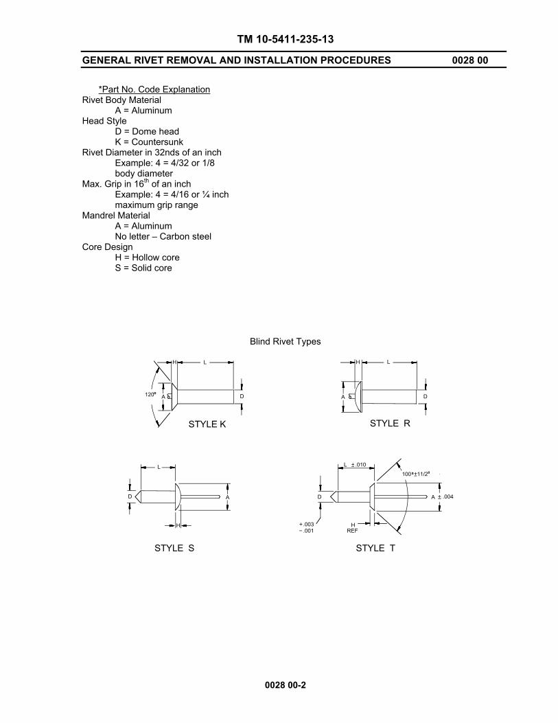
Tools: General Mechanics Tool Kit ( WP 0042, Table 2, Item 1) Riveting Tool (WP 0042, Table 2, Item 02) Rosan Insert Tool (WP 0042, Table 2, Item 05) Drill (WP 0042, Table 2, Item 04) Safety Goggles (WP 0044, Table 1, Item 35) Materials/Parts: Rivets (See Table 2) Sealer (WP 0044, Table 1, Item 19) GENERAL. These procedures are general procedures that may be needed during repair or replacement of shelter components. Wherever these general procedures apply, they are referenced at the appropriate point in the specific maintenance procedure paragraph. Blind Rivet Installation and Removal. Blind rivets are used in locations where only one side of the area to be worked on is accessible. Blind pop rivets must be used in the shelter honeycomb panels since the hammering required to install conventional rivets would damage the material. Type of rivets used in the shelter are described in Table 2 and shown in following illustration. When installing floor patches, countersunk head rivets (styles K and T) are preferred, but dome head rivets (styles R and S) are an acceptable alternative. When installing interior wall patches, countersunk head rivets shall be used in any instance where dome head rivets will interfere with the installation of equipment. Closed end rivets (styles K and R) must be used for exterior repairs and floor repairs to prevent moisture and dirt from entering panels.
Table 2. Blind Rivets
* Part No. Style Dim A Dim H Dim D Dim L AD42H R 0.236 0.051 1/8 0.361 AD43H R 0.236 0.051 1/8 0.377 AD45H R 0.236 0.051 1/8 0.502 AD62H R 0.375 0.081 3/16 0.345 AD64H R 0.375 0.081 3/16 0.470 AD68H R 0.375 0.081 3/16 0.720 AD42S R 0.236 0.051 1/8 0.361
MS20470AD6-8 R 0.250 0.067 3/16 0.375 NAS1398D4-3 R 0.250 0.067 0.156 0.326 NAS1398D4-4 R 0.250 0.067 0.456 0.388 NAS1398D6-3 R 0.375 0.080 0.187 0.350 NAS1398D6-5 R 0.375 0.080 0.187 0.475 NAS1398D6-8 R 0.375 0.080 0.187 0.662 NAS1399D4-4 R 0.225 0.042 0.125 0.385 NAS1399D4-6 R 0.353 0.070 0.187 0.537 NAS1739E4-3 R 0.286 0.047 0.173 0.375
TM 10-5411-235-13
GENERAL RIVET REMOVAL AND INSTALLATION PROCEDURES 0028 00
0028 00-2
*Part No. Code Explanation
Rivet Body Material A = Aluminum Head Style D = Dome head K = Countersunk Rivet Diameter in 32nds of an inch Example: 4 = 4/32 or 1/8 body diameter Max. Grip in 16th of an inch Example: 4 = 4/16 or ¼ inch maximum grip range Mandrel Material A = Aluminum No letter – Carbon steel Core Design H = Hollow core S = Solid core
Blind Rivet Types
H L
A D
H H
H
L
L
L
A A
A D
DD
120
STYLE K STYLE R
STYLE S STYLE T
.003
.001 REF
.004
100 11/2
.010

TM 10-5411-235-13
DIRECT SUPPORT MAINTENANCE-GENERAL RIVET REMOVAL AND INSTALLATION PROCEDURES 0028 00
0028 00-3
NOTE Open end rivets may be used only where moisture and dirt intrusion will not affect the shelter.
1. Installation
NOTE When installing new rivets in the same location as a rivet that has been removed, if diameter of hole in structure has been enlarged during removal of rivet, use next larger diameter rivet for replacement. Clean rivets with solvent before installing.
Determine type, size, and grip range of rivet to be used. Grip length equals the combined thickness of the materials being riveted together. Grip range of the rivet must encompass the grip length.
WARNING
Drilling creates metal chips which may enter eyes and cause serious injury. Eye protection is required.
CAUTION Make sure drill bit has a stop attached which will prohibit the drill from exceeding a depth of one inch.
NOTE Drill hole size must match the side of the rivet being used. Quantities of sheets may be drilled at the same time when held together with steel fasteners.
a. Drill hole in structure. b. Remove all metal chips and burrs from drilled holes.
c. If flush head rivet is being installed, countersink hole using a 100-degree machine countersink.
d. Coat all rivet bodies with fiber polyester resin (WP 0044, Table 1, Item 10) before installing.
e. Insert rivet in hole. Make sure sheets are held tightly together before upsetting or pulling
rivet.
f. Select proper pulling head for rivet being installed and install pulling head on rivet gun.
g. Insert stem of rivet into pulling head.
h. With pulling head parallel to axis of rivet, upset rivet. Exert firm pressure but do not bend or buckle metal sheets. Stem will break off below rivet head surface. No trimming should be required.
i. Make sure riveted parts are not loose, rivet does not rotate, and rivet head is seated tightly
against riveted surface. If rivet is loose or improperly installed, remove the rivet and repeat steps (a) through (i).
j. Reapply external sealant.

TM 10-5411-235-13
DIRECT SUPPORT MAINTENANCE-GENERAL RIVET REMOVAL AND INSTALLATION PROCEDURES 0028 00
0028 00-4
PROPER INSTALLATION
RIVETTOO SHORT
RIVETTOO LONG
HOLE TOOLARGE
OBLIQUEHOLE
1.
2.
3.
POSITIONPULLINGHEAD ONRIVET
STEM BREAKSWHEN RIVET ISFULLY FORMED
PROPERLYINSTALLEDRIVET
IMPROPER INSTALLATION
GRIP LENGTHPULLINGHEAD

TM 10-5411-235-13
DIRECT SUPPORT MAINTENANCE-GENERAL RIVET REMOVAL AND INSTALLATION PROCEDURES 0028 00
0028 00-5/(6 Blank)
2. Removal
WARNING
Drilling creates metal chips which may enter eyes and cause serious injury. Eye protection is required.
CAUTION Make sure drill bit has a stop attached which will prohibit the drill from exceeding a depth of one inch.
NOTE When drilling through rivet head, be careful to avoid enlarging hole in structure. Keep drill perpendicular to material being drilled and do not exert excessive pressure on drill, or replacement rivets will be too loose.
a. Drill through head of rivet only, using hole in rivet as a guide. Use the proper drill size
as follows: Rivet Size (in.) Drill Size 1/8 No. 30 5/32 No. 20 3/16 No. 11 ¼ ¼ inch
b. Using a pin punch, pry off rivet head.
CAUTION Do not punch rivet shanks out as you may damage the other side of the panel.
c. Using a pin punch, push out rivet shank.
END OF WORK PACKAGE
PUSH OUTSHANK
PRY OFFHEAD
DRILLTHROUGH
HEAD


TM 10-5411-235-13
DIRECT SUPPORT MAINTENANCE-GENERAL RIVNUT REMOVAL AND INSTALLATION PROCEDURES 0029 00
0029 00-1
THIS WORK PACKAGE COVERS: Replace INITIAL SETUP: Maintenance Level Direct
Tools: General Mechanics Tool Kit ( WP 0042, Table 2, Item 1) Riveting Tool (WP 0042, Table 2, Item 02) Rosan Insert Tool (WP 0042, Table 2, Item 05) Drill (WP 0042, Table 2, Item 04) Safety Goggles (WP 0044, Table 1, Item 35) Materials/Parts: Rivnuts (See Table 1) Sealer (WP 0044, Table 1, Item 19) Rivnut Installation and Removal. Rivnuts (threaded inserts) are tubular rivets with internal threads and are used throughout the shelter wherever blind threads are required. The types of rivnuts used in the LMS Type 1 Shelter are shown in below and described in Table 1.
NOTE Flat head rivnuts (style D and E) may be used wherever head thickness will not interfere with the installation of equipment. Countersunk head rivnuts (style C) are used for flush installation. Keyed rivnuts are used in locations which are subject to vibration and torque. Closed end rivnuts (styles C and E) must be used for exterior repairs and floor repairs to keep moisture and dirt from entering panels. Open end rivnuts (style D) may be used in areas where sealing is not required.
L
100°
A DIA D DIA D DIA
L
A DIA
A DIA D DIA
C
T THREAD
STYLE C
T THREAD
T THREAD
STYLE E
STYLE D
C L

TM 10-5411-235-13
DIRECT SUPPORT MAINTENANCE-GENERAL RIVNUT REMOVAL AND INSTALLATION PROCEDURES 0029 00
0029 00-2
1. Installation
NOTE When installing new rivnuts in the same location as a rivnut that has been removed, use the next larger diameter rivnut for replacement if diameter of the hole in the structure was enlarged during removal.
Determine thread size, grip range, style, and material of rivnut to be used. Grip length equals combined thickness of materials being fastened together. Grip range of rivnuts must encompass grip length.
GRIPLENGTH
FLAT HEADRIVNUT INSERTEDIN DRILLED HOLE
COUNTERSINKHEAD RIVNUTINSERTED IN
DRILLED HOLE
PROPERLYINSTALLED
RIVNUT
PULLUP STUDTHREADED INTO
RIVNUT
TM 10-5411-235-13
DIRECT SUPPORT MAINTENANCE-GENERAL RIVNUT REMOVAL AND INSTALLATION PROCEDURES 0029 00
0029 00-3
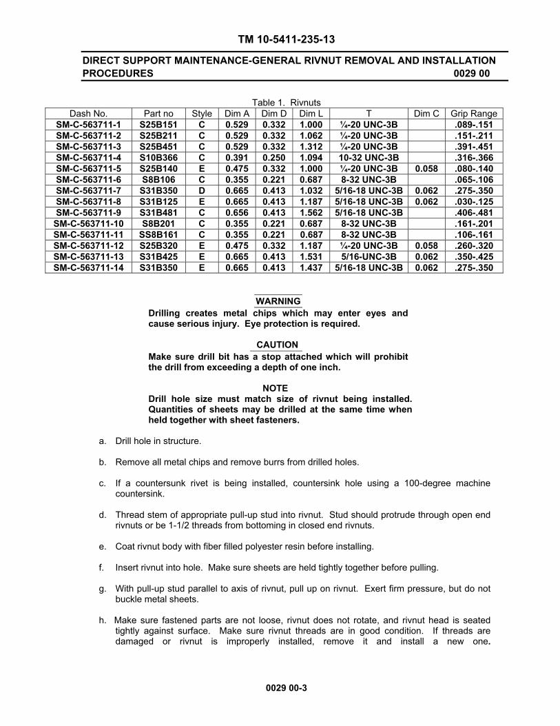
Table 1. Rivnuts
Dash No. Part no Style Dim A Dim D Dim L T Dim C Grip Range SM-C-563711-1 S25B151 C 0.529 0.332 1.000 ¼-20 UNC-3B .089-.151 SM-C-563711-2 S25B211 C 0.529 0.332 1.062 ¼-20 UNC-3B .151-.211 SM-C-563711-3 S25B451 C 0.529 0.332 1.312 ¼-20 UNC-3B .391-.451 SM-C-563711-4 S10B366 C 0.391 0.250 1.094 10-32 UNC-3B .316-.366 SM-C-563711-5 S25B140 E 0.475 0.332 1.000 ¼-20 UNC-3B 0.058 .080-.140 SM-C-563711-6 S8B106 C 0.355 0.221 0.687 8-32 UNC-3B .065-.106 SM-C-563711-7 S31B350 D 0.665 0.413 1.032 5/16-18 UNC-3B 0.062 .275-.350 SM-C-563711-8 S31B125 E 0.665 0.413 1.187 5/16-18 UNC-3B 0.062 .030-.125 SM-C-563711-9 S31B481 C 0.656 0.413 1.562 5/16-18 UNC-3B .406-.481
SM-C-563711-10 S8B201 C 0.355 0.221 0.687 8-32 UNC-3B .161-.201 SM-C-563711-11 SS8B161 C 0.355 0.221 0.687 8-32 UNC-3B .106-.161 SM-C-563711-12 S25B320 E 0.475 0.332 1.187 ¼-20 UNC-3B 0.058 .260-.320 SM-C-563711-13 S31B425 E 0.665 0.413 1.531 5/16-UNC-3B 0.062 .350-.425 SM-C-563711-14 S31B350 E 0.665 0.413 1.437 5/16-18 UNC-3B 0.062 .275-.350
WARNING Drilling creates metal chips which may enter eyes and cause serious injury. Eye protection is required.
CAUTION Make sure drill bit has a stop attached which will prohibit the drill from exceeding a depth of one inch.
NOTE Drill hole size must match size of rivnut being installed. Quantities of sheets may be drilled at the same time when held together with sheet fasteners.
a. Drill hole in structure.
b. Remove all metal chips and remove burrs from drilled holes.
c. If a countersunk rivet is being installed, countersink hole using a 100-degree machine
countersink. d. Thread stem of appropriate pull-up stud into rivnut. Stud should protrude through open end
rivnuts or be 1-1/2 threads from bottoming in closed end rivnuts.
e. Coat rivnut body with fiber filled polyester resin before installing.
f. Insert rivnut into hole. Make sure sheets are held tightly together before pulling.
g. With pull-up stud parallel to axis of rivnut, pull up on rivnut. Exert firm pressure, but do not buckle metal sheets.
h. Make sure fastened parts are not loose, rivnut does not rotate, and rivnut head is seated
tightly against surface. Make sure rivnut threads are in good condition. If threads are damaged or rivnut is improperly installed, remove it and install a new one.
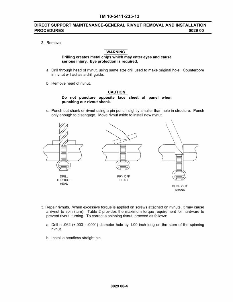
TM 10-5411-235-13
DIRECT SUPPORT MAINTENANCE-GENERAL RIVNUT REMOVAL AND INSTALLATION PROCEDURES 0029 00
0029 00-4
2. Removal
WARNING
Drilling creates metal chips which may enter eyes and cause serious injury. Eye protection is required.
a. Drill through head of rivnut, using same size drill used to make original hole. Counterbore
in rivnut will act as a drill guide. b. Remove head of rivnut.
CAUTION
Do not puncture opposite face sheet of panel when punching our rivnut shank.
c. Punch out shank or rivnut using a pin punch slightly smaller than hole in structure. Punch
only enough to disengage. Move rivnut aside to install new rivnut.
3. Repair rivnuts. When excessive torque is applied on screws attached on rivnuts, it may cause a rivnut to spin (turn). Table 2 provides the maximum torque requirement for hardware to prevent rivnut turning. To correct a spinning rivnut, proceed as follows:
a. Drill a .062 (+.003 - .0001) diameter hole by 1.00 inch long on the stem of the spinning
rivnut. b. Install a headless straight pin.
PUSH OUTSHANK
PRY OFFHEAD
DRILLTHROUGH
HEAD

TM 10-5411-235-13
DIRECT SUPPORT MAINTENANCE-GENERAL RIVNUT REMOVAL AND INSTALLATION PROCEDURES 0029 00
0029 00-5/(6 Blank)
Spinning Rivnut Repair
Table 2. Maximum Torque Requirements for Rivnut Screws
Screw Size Torque (lbs/in.) 4 – 40 8 lb/inch 6 – 32 12 lb/inch 8 – 32 20 lb/inch 10 – 32 20 lb/inch ¼ – 20 50 lb/inch
5/16 – 18 65 lb/inch 3/8 – 16 120 lb/inch
END OF WORK PACKAGE


TM 10-5411-235-13
REPAIR OF SHELTER DENT 0030 00
0030 00-1
THIS WORK PACKAGE COVERS: Repair INITIAL SETUP: Maintenance Level Direct Support
Tools: General Mechanics Tool Kit (WP 0042, Table 2, Item 1) Oscillating Sander (WP 0042, Table 2, Item 7) Safety Goggles (WP 0044, Table 1, Item 35) Materials/Parts: Alcohol, Isopropyl (WP 0044, Table 1, Item 7) Cloth, cotton (WP 0044, Table 1, Item 3) Polysulfide sealer (WP 0044, Table 1, Item 2) Gloves, rubber (WP 0044, Table 1, Item 11) Sandpaper (WP 0044, Table 1, Item 12) Commercial Body Filler (WP 0044, Table 1, Item 8) REPAIR
WARNING • To avoid injury to personnel, safety glasses must be
worn during drilling and sanding operations. • Alcohol solvents are flammable. Keep away from heat,
sparks and open flame. Keep containers closed when not in use. Use only in well ventilated areas. Avoid prolonged breathing of vapors or repeated contact with skin.
1. Using an oscillating sander, roughen the area to be repaired.
NOTE This repair procedure is for damaged areas not exceeding 100 square inches in area and located between structural members. To determine whether a large or deep dent is between structural members, tap area with finger. A structural member has a tight drum-like sound while the area between has a soft sound between members. Extensive damage such as denting or buckling of the exterior shelter skin (which displaces the opposite shelter skin), generally constitutes an unrepairable type of damage.

TM 10-5411-235-13
REPAIR OF SHELTER DENT 0030 00
0030 00-2
NOTE
Make sure that the area is completely clean. Do not touch the area with hands or any item that may leave an oily residue.
2. Wear rubber gloves and use a clean cotton cloth with alcohol and clean the entire surface. 3. Fill the dent with body filler using a putty knife or other flat-edge implement and smooth the
surface evenly to a feathered edge. 4. Allow the resin to set thoroughly (approximately one hour, depending on ambient air temperature)
in accordance with manufacturer’s recommendations. 5. Sand the repaired area to a flat, smooth finish. 6. Prime and paint the repaired surface in accordance with local Standard Operating Procedures
(SOP).
END OF WORK PACKAGE
DENTHONEYCOMBCORE
EXTERIORSKIN
REPAIR MIX EXTERIOR SKIN
INTERIOR SKIN
INTERIOR SKIN
TM 10-5411-235-13
REPAIR OF SHELTER PANEL PUNCTURE - NO CORE DAMAGE 0031 00
0031 00-1
THIS WORK PACKAGE COVERS: Repair INITIAL SETUP: Maintenance Level Direct Support
Tools: General Mechanics Tool Kit (WP 0042, Table 2, Item 1) Riveting Tool (WP 0042, Table 2, Item 2) Oscillating Sander ( WP 0042, Table 2, Item 7) Drill (WP 0042, Table 2, Item 4) Materials/Parts: Alcohol, Isopropyl (WP 0044, Table 1, Item 7) Polysulfide sealer (WP 0044, Table 1, Item 2) Commercial Body Filler (WP 0044, Table 1, Item 8) Cloth, cotton (WP 0044, Table 1, Item 3) Dome Head Pop-Rivets (WP 0044, Table 1, Items 27 & 28) Sandpaper (WP 0044, Table 1, Item 12) Gloves, rubber (WP 0044, Table 1, Item 11) Aluminum Patch (WP 0044, Table 1, Item 13) REPAIR
1. Select an aluminum patch that overlaps the puncture or cut by one inch in all directions.
2. Roughen the skin surface with 80 grit abrasive paper.
WARNING Alcohol solvents are flammable. Keep away from heat, sparks, and open flame. Keep containers closed when not in use. Use only in well ventilated areas. Avoid prolonged breathing of vapors or repeated contact with skin.
NOTE Make sure that the area is completely clean. Do not touch the area with hands or any item that may leave an oily residue.
3. Wear rubber gloves and use a clean cloth with isopropyl alcohol to remove all dust and residue.
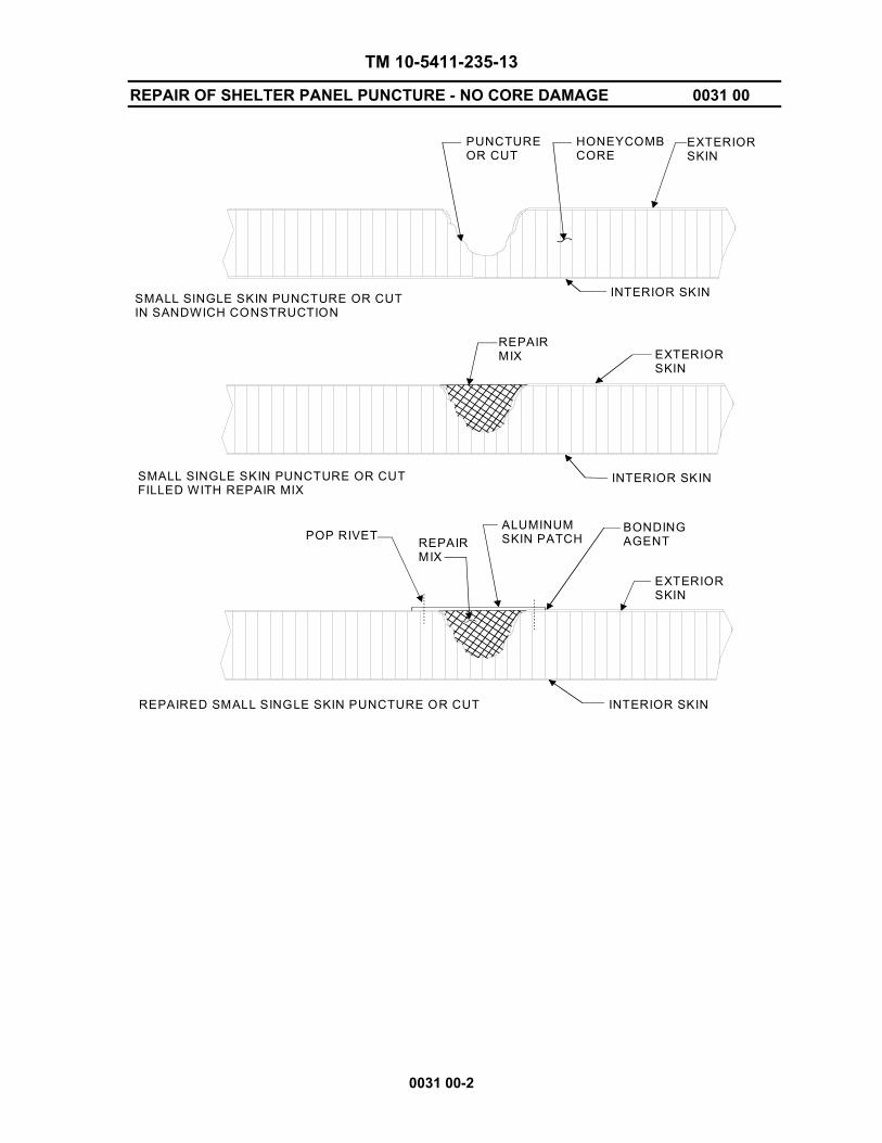
TM 10-5411-235-13
REPAIR OF SHELTER PANEL PUNCTURE - NO CORE DAMAGE 0031 00
0031 00-2
PUNCTUREOR CUT
HONEYCOMBCORE
INTERIOR SKIN
INTERIOR SKIN
EXTERIORSKIN
EXTERIORSKIN
INTERIOR SKIN
EXTERIORSKIN
REPAIRMIX
POP RIVET REPAIRMIX
ALUMINUMSKIN PATCH
BONDINGAGENT
SMALL SINGLE SKIN PUNCTURE OR CUTIN SANDWICH CONSTRUCTION
SMALL SINGLE SKIN PUNCTURE OR CUTFILLED WITH REPAIR MIX
REPAIRED SMALL SINGLE SKIN PUNCTURE OR CUT

TM 10-5411-235-13
REPAIR OF SHELTER PANEL PUNCTURE - NO CORE DAMAGE 0031 00
0031 00-3/(4 Blank)
WARNING
To avoid injury to personnel, safety glasses must be worn during drilling and sanding operations.
4. Fill the puncture and surrounding dented area with body filler using a putty knife.
5. Allow the resin to cure thoroughly (approximately one hour depending on ambient air temperature) in accordance with manufacturers recommendations.
6. Use an oscillating sander and sand the repaired area to a flat, smooth finish, flush with
the contour of the skin surface.
WARNING Drilling creates metal chips which may enter eyes and cause serious injury. Eye protection is required.
CAUTION Make sure drill but has a stop attached which will prohibit the drill from exceeding a depth of 5/8 inch.
7. Locate the aluminum patch to the shelter and drill holes for 3/16 inch pop-rivets (#11 drill) through the patch and the skin of the shelter (approximately one inch spacing between centers and ½ inch from the edge).
WARNING
To avoid injury to personnel, gloves must be worn when working with polysulfide sealer.
8. Dip pop-rivets in polysulfide sealer, and use a pop-rivet gun to secure aluminum patch to shelter skin.
9. Remove the excess polysulfide sealer squeezed out during the riveting process.
10. Apply polysulfide sealer around perimeter of patch.
11. Prime and paint the repaired surface in accordance with local Standard Operating Procedures (SOP).
END OF WORK PACKAGE


TM 10-5411-235-13
REPAIR OF SHELTER PANEL PUNCTURE - DAMAGE TO CORE 0032 00
0032 00-1
THIS WORK PACKAGE COVERS: Repair INITIAL SETUP: Maintenance Level Direct Support
Tools: General Mechanics Tool Kit (WP 0042, Table 2, Item 1) Circular Saw (WP 0042, Table 2, Item 8) Drill (WP 0042, Table 2, Item 4) Oscillating Sander (WP 0042, Table 2, Item 7) Riveting Tool (WP 0042, Table 2, Item 2) Safety Goggles (WP 0044, Table 1, Item 35) Materials/Parts: Alcohol, Isopropyl (WP 0044, Table 1, Item 7) Aluminum Patch (WP 0044, Table 1, Item 13) Cloth, cotton (WP 0044, Table 1, Item 7) Dome Head Pop-Rivets (WP 0044, Table 1, Items 27 & 28) Sandpaper (WP 0044, Table 1, Item 12) Polysulfide Sealer (WP 0044, Table 1, Item 2) Adhesive (WP 0044, Table 1, Item 32) Commercial Body Filler (WP 0044, Table 1, Item 8) Core, honeycomb (WP 0044, Table 1, Item 9) Gloves, rubber (WP 0044, Table 1, Item 11) REPAIR
NOTE The following repair procedures are for damaged skin between structural members. If the puncture or cut did not seriously damage the honeycomb core, follow the procedures in WP 0028. If the puncture or cut damaged the honeycomb core, perform the following procedures.
1. Use a circular saw and make a cutout by removing approximately one inch of skin around the outside of the puncture.
2. Select an aluminum patch that overlaps the cut out by one inch in all directions.
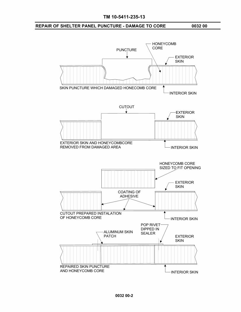
TM 10-5411-235-13
REPAIR OF SHELTER PANEL PUNCTURE - DAMAGE TO CORE 0032 00
0032 00-2
PUNCTUREHONEYCOMBCORE
EXTERIORSKIN
INTERIOR SKIN
CUTOUT
INTERIOR SKIN
EXTERIORSKIN
EXTERIORSKIN
COATING OF ADHESIVE
INTERIOR SKIN
HONEYCOMB CORESIZED TO FIT OPENING
INTERIOR SKIN
EXTERIORSKIN
SKIN PUNCTURE WHICH DAMAGED HONECOMB CORE
EXTERIOR SKIN AND HONEYCOMBCOREREMOVED FROM DAMAGED AREA
CUTOUT PREPARED INSTALATIONOF HONEYCOMB CORE
REPAIRED SKIN PUNCTUREAND HONEYCOMB CORE
ALUMINUM SKINPATCH
POP RIVETDIPPED INSEALER
TM 10-5411-235-13
REPAIR OF SHELTER PANEL PUNCTURE - DAMAGE TO CORE 0032 00
0032 00-3/(4 Blank)
CAUTION When cutting honeycomb core, use care to ensure the interior skin is not cut.
3. Using a putty knife, cut through the damaged honeycomb core using the edge of the cutout as a guide.
4. Remove the damaged honeycomb material.
5. Size a block of honeycomb core for the cutout. Ensure the honeycomb is the same thickness, length, width of the cutout.
WARNING
To avoid injury to personnel, safety glasses must be worn during drilling and sanding operations.
CAUTION Make sure drill bit has a stop attached which will prohibit the drill from exceeding a depth of 5/8 inch.
6. Locate the aluminum patch to the shelter and pre-drill holes for 3/16 inch pop-rivets (#11 drill bit) through the patch and skin of the shelter (approximately one inch spacing between centers and ½ inch from the edge of the patch).
7. Set patch aside for later use. WARNING
To avoid injury or death to personnel, no smoking is allowed when working with flammable materials.
WARNING To avoid injury to personnel, gloves must be worn when working with adhesive.
8. Coat the interior opening of the cutout and the entire surface of the replacement honeycomb with adhesive.
9. Insert the replacement honeycomb block into cutout.
10. Locate the skin patch to the shelter. WARNING
To avoid injury or death to personnel, no smoking is allowed when working with flammable materials.
WARNING To avoid injury to personnel, gloves must be worn when working with adhesive.
11. Dip the pop-rivets in polysulfide sealer and use a pop-rivet gun to secure skin patch to the shelter.
12. Remove the excess polysulfide sealer and adhesive squeezed out during the riveting process.
13. Apply polysulfide sealer around perimeter of patch.
14. Prime and paint the repaired surface in accordance with local Standard Operating Procedures (SOP). END OF WORK PACKAGE


TM 10-5411-235-13
REPAIR OF SHELTER PANEL DELAMINATION 0033 00
0033 00-1
THIS WORK PACKAGE COVERS: Inspect, Repair INITIAL SETUP: Maintenance Level Direct Support
Tools: General Mechanics Tool Kit (WP 0042, Table 2, Item 1) Tapping Hammer (WP 0042, Table 2, Item 3) Riveting Tool (WP 0042, Table 2, Item 2) Drill (WP 0042, Table 2, Item 4) Caulking Gun (WP 0042, Table 2, Item 6) Materials/Parts: Alcohol, Isopropyl (WP 0044, Table 1, Item 7) Caulking Cartridge (WP 0044, Table 1, Item 14) Polyethylene Wrap (WP 0044, Table 1, Item 6) Cloth, cotton (WP 0044, Table 1, Item 3) Chalk (WP 0044, Table 1, Item 5) Adhesive (WP 0044, Table 1, Item 4) Epoxy base and accelerator (Epic and Versamid) (Items WP 0044, Table 1, Item 16 & 17) Polysulfide Sealer (WP 0044, Table 1, Item 2) Gloves, rubber (WP 0044, Table 1, Item 11) Dome Head Pop-Rivets (WP 0044, Table 1, Item 27) Container, Unwaxed (WP 0044, Table 1, Item 15) INSPECT 1. The area between the inner and outer aluminum panels is filled with a honeycomb core bonded to
the panels with an epoxy adhesive. Separation of this core from the aluminum panel will cause a structural weakness in the affected area. Large delaminations should be repaired as soon as possible.
2. Delaminated areas produce a light hollow sound similar to the sound the bottom of an oil can
makes when pressed. A bonded area produces a dull solid sound. The sound may change somewhat when crossing structural members.
3. Using a tapping hammer, inspect the roof, floor, endwalls, and sidewalls of the inner and outer
aluminum panels attached to structural members for the hollow sound. REPAIR 1. Mark off the limits of the delamination using chalk.
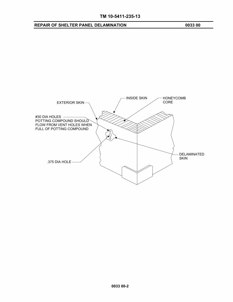
TM 10-5411-235-13
REPAIR OF SHELTER PANEL DELAMINATION 0033 00
0033 00-2
INSIDE SKIN HONEYCOMBCORE
DELAMINATEDSKIN
.375 DIA HOLE
EXTERIOR SKIN
#30 DIA HOLESPOTTING COMPOUND SHOULDFLOW FROM VENT HOLES WHENFULL OF POTTING COMPOUND

TM 10-5411-235-13
REPAIR OF SHELTER PANEL DELAMINATION 0033 00
0033 00-3
WARNING
To avoid injury to personnel, safety glasses must be worn during drilling and sanding operations.
CAUTION
Make sure the drill bit has a drill stop attached to prevent the drill bit from exceeding a depth of 5/8 inch.
2. Using a drill with a #11 bit, drill clearance holes (number of holes is dependent on the size of the delamination) for 3/16 inch pop-rivets spaced (not greater than five inches on center) within the chalk line.
3. Using the outline of the marked delaminated area, make the surrounding area approximately two feet wide with polyethylene.
WARNING
To avoid injury to personnel, gloves must be worn when working with adhesive.
4. In a clean unwaxed container, mix Epic R1002 adhesive with Versamid 140 material as follows:
• By Weight: 15 oz. Epic to 5 oz. Versamid
• By Volume: 2 parts Epic to 1 part Versamid
NOTE
The mixed adhesive must be used within the time specified below, considering the ambient temperature.
60°F – 2 hours
70°F – 1 hour
80°F – 40 minutes
90°F – 20 minutes
CAUTION
Inject adhesive slowly. Too much force could increase the size of the delamination and cause additional damage.
5. Using a caulking gun, inject adhesive into the bottom hole until adhesive begins to seep out of the holes in line with the injection hole.
6. Using a pop-rivet gun, (dip rivet in polysulfide sealer for exterior delaminations), install one 3/16 inch rivet in the hole.
7. When the holes on each side of the injection hole are riveted, install a rivet in the injection hole and use the next series of pre-drilled holes to continue injecting adhesive.
8. Repeat steps 5 through 7 until all holes are filled with adhesive and pop-rivets.
9. Clean the excess adhesive with non-residual cleaning solvent (Isopropyl alcohol).

TM 10-5411-235-13
REPAIR OF SHELTER PANEL DELAMINATION 0033 00
0033 00-4
10. Apply a fixed, even surface pressure to the area for a minimum of 12 hours to ensure that the skin of the shelter is held in contact with the honeycomb core, and allow the adhesive to cure.
11. Prime and paint repaired panel surface in accordance with local Standard Operating Procedures (SOP).
END OF WORK PACKAGE

TM 10-5411-235-13
LIFTING RING BUMPER 0034 00
0034 00-1
THIS WORK PACKAGE COVERS: Replace INITIAL SETUP: Maintenance Level Direct Support
Tools: General Mechanics Tool Kit (WP 0042, Table 2, Item 1) Drill (WP 0042, Table 2, Item 4) Riveting Tool (WP 0042, Table 1, Item 2) Safety Goggles (WP 0044, Table 1, Item 35) Materials/Parts: Bumper Rivet, Dome Head (WP 0044, Table 1, Item 27) Rivet, Dome Head (WP 0044, Table 1, Item 28) Alcohol, Isopropyl (WP 0044, Table 1, Item 7) Cloth, Cotton (WP 0044, Table 1, Item 3) Sealer (WP 0044, Table 1, Item 19) REPLACE REMOVE
WARNING Drilling creates metal chips which may enter eyes and cause serious injury. Eye protection is required.
CAUTION Make sure the drill bit has a drill stop attached to prevent the drill bit from exceeding a depth of one inch.
NOTE A shim is located under the front bumpers and a longer rivet is installed in the most forward hole of each.
1. Using a drill with a #11 drill bit, carefully drill out two rivets securing bumper (1) to shelter and remove bumper.
INSTALL 1. Position bumper (1) to shelter.
2. Align holes and secure rear bumper (1) in position with two rivets (2). 3. Apply sealant. 4. Prime and paint surface panels in accordance with local Standard Operating Procedures (SOP).
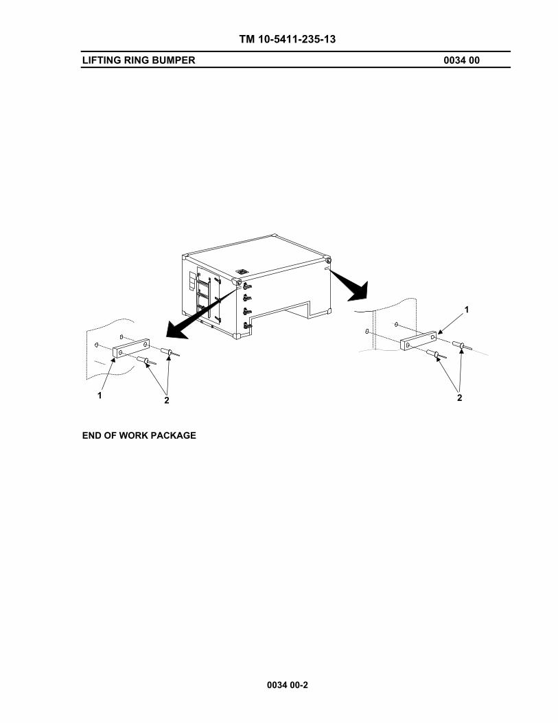
TM 10-5411-235-13
LIFTING RING BUMPER 0034 00
0034 00-2
1
1
2 2
END OF WORK PACKAGE

TM 10-5411-235-13
REPAIR OF SHELTER DOOR DRIP MOLDING 0035 00
0035 00-1
THIS WORK PACKAGE COVERS: Replace INITIAL SETUP: Maintenance Level Direct Support
Tools: Drill (WP 0042, Table 2, Item 4) Safety Goggles (WP 0044, Table 1, Item 35) Riveting Tool (WP 0042, Table 1, Item 2) Materials/Parts: Dome Head Pop-Rivets (WP 0044, Table 1, Items 27 & 28) Drip Molding Sealer (WP 0044, Table 1, Item 19) Alcohol, Isopropyl (WP 0044, Table 1, Item 7) Cloth, Cotton (WP 0044, Table 1, Item 3) REPLACE REMOVE
WARNING Drilling creates metal chips which may enter eyes and cause serious injury. Eye protection is required.
CAUTION Make sure the drill bit has a drill stop attached to prevent the drill bit from exceeding a depth of one inch.
1. Remove sealant. 2. Using a drill with a #11 drill bit, carefully drill out seven rivets (2) securing drip molding (1) to
shelter.
3. Remove drip molding (1). INSTALL 1. Locate drip molding (1) to shelter and insert seven rivets (2) through holes in drip molding (1) and
into holes in shelter. 2. Using a pop-rivet tool, secure drip molding (1) to shelter. 3. Replace sealant. 4. Prime and paint repaired panel surface in accordance with local Standard Operating Procedures
(SOP).
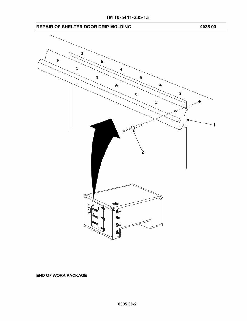
TM 10-5411-235-13
REPAIR OF SHELTER DOOR DRIP MOLDING 0035 00
0035 00-2
2
1
END OF WORK PACKAGE
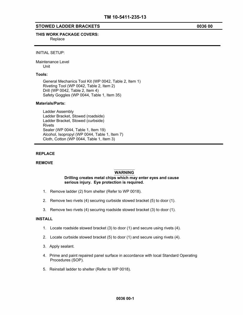
TM 10-5411-235-13
STOWED LADDER BRACKETS 0036 00
0036 00-1
THIS WORK PACKAGE COVERS: Replace INITIAL SETUP: Maintenance Level Unit
Tools: General Mechanics Tool Kit (WP 0042, Table 2, Item 1) Riveting Tool (WP 0042, Table 2, Item 2) Drill (WP 0042, Table 2, Item 4) Safety Goggles (WP 0044, Table 1, Item 35) Materials/Parts: Ladder Assembly Ladder Bracket, Stowed (roadside) Ladder Bracket, Stowed (curbside) Rivets Sealer (WP 0044, Table 1, Item 19) Alcohol, Isopropyl (WP 0044, Table 1, Item 7) Cloth, Cotton (WP 0044, Table 1, Item 3) REPLACE REMOVE
WARNING Drilling creates metal chips which may enter eyes and cause serious injury. Eye protection is required.
1. Remove ladder (2) from shelter (Refer to WP 0018). 2. Remove two rivets (4) securing curbside stowed bracket (5) to door (1).
3. Remove two rivets (4) securing roadside stowed bracket (3) to door (1).
INSTALL
1. Locate roadside stowed bracket (3) to door (1) and secure using rivets (4).
2. Locate curbside stowed bracket (5) to door (1) and secure using rivets (4).
3. Apply sealant.
4. Prime and paint repaired panel surface in accordance with local Standard Operating Procedures (SOP).
5. Reinstall ladder to shelter (Refer to WP 0018).

TM 10-5411-235-13
STOWED LADDER BRACKETS 0036 00
0036 00-2
21
3
4
5
END OF WORK PACKAGE

TM 10-5411-235-13
FLOOR DRAIN PLUG 0037 00
0037 00-1
THIS WORK PACKAGE COVERS: Replace INITIAL SETUP: Maintenance Level Direct Support
Tools: Drill (WP 0042, Table 2, Item 4) Safety Goggles (WP 0044, Table 1, Item 35) Riveting Tool (WP 0042, Table 2, Item 2) Materials/Parts: Dome Head Pop-Rivets (WP 0044, Table 1, Items 27 & 28) Floor Drain Plug REMOVE
WARNING Drilling creates metal chips which may enter eyes and cause serious injury. Eye protection is required.
CAUTION Make sure the drill bit has a drill stop attached to prevent drill bit from exceeding a depth of one inch.
1. Using a drill, carefully drill out the the rivet (2) securing chain to floor.
2. Remove drain plug and chain (1). INSTALL 1. Install drain plug into pan.
2. Install rivet (2) securing chain to floor.

TM 10-5411-235-13
FLOOR DRAIN PLUG 0037 00
0037 00-2
1
2
END OF WORK PACKAGE
TM 10-5411-235-13
INSTALLATION OF LMS I SHELTER TO HMMWV 0038 00
0038 00-1
THIS TASK COVERS:
Installation of Shelter and Pintle Extension Kit
INITIAL SETUP:
Tools and Special Tools
General Mechanics Tool Kit (WP 0042, Table 2, Item 1)
Materials/Parts
Refer to WP 0043
VEHICLE PREPARATION
CAUTION
Packing list and illustrations should always be retained with the LMS Shelter for future use. Do not remove or damage packing list.
NOTE
• For shelters to be replaced or moved from one vehicle to another and for any component of the installation mounting kit which requires maintenance, perform only the steps which are applicable.
• Prior to performing the following procedures, remove Shelter-to-Vehicle Mounting Kit and inventory per WP 0043, Table 3.
1. Remove wheel well side panel located on each side of vehicle. Reference HMMWV TM 9-4940-563-13&P.
2. Carefully feed antenna cable back through wheel well grommet, place protective cap over connectors, and secure cables behind cross member support in wheel well.
3. From inside the curbside rear wheel well, remove the wiring harness clamp mounting bracket. Remove cable clamps from wiring.
4. Remove tailgate from rear of HMMWV per TM 9-4940-563-13&P.
5. Remove antenna mounting bracket from rear of HMMWV per TM 9-4940-563-13&P.
6. Remove tail lights from HMMWV lower frame per TM 9-4940-563-13&P. Retain hardware.
7. Secure tail lights (1) to tail light mounting brackets (2) and wiring ground lug (3) using bolts (4) and washers (5) removed in step 6.
8. Make a single cut through grommet (6) and place it around the tail light wiring (7).
9. Remove camlock fasteners from the vehicle mounting beam located in front of the vehicle's bed, both sides. Refer to TM 9-4940-563-13&P.
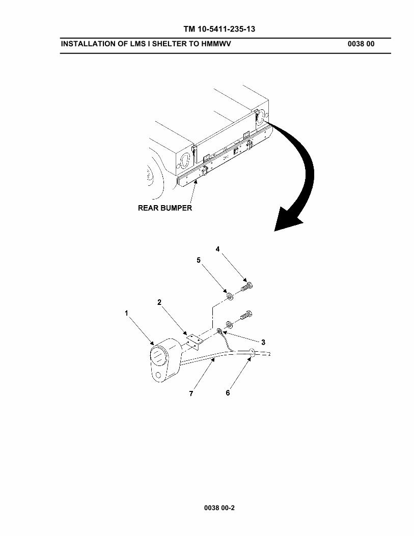
TM 10-5411-235-13
INSTALLATION OF LMS I SHELTER TO HMMWV 0038 00
0038 00-2
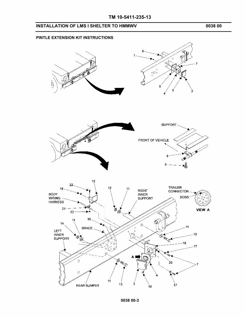
TM 10-5411-235-13
INSTALLATION OF LMS I SHELTER TO HMMWV 0038 00
0038 00-3
PINTLE EXTENSION KIT INSTRUCTIONS
TM 10-5411-235-13
INSTALLATION OF LMS I SHELTER TO HMMWV 0038 00
0038 00-4
1. Remove towing pintle assembly from HMMWV bumper. Reference HMMWV TM 9-4940-563-13&P. Retain towing pintle assembly and mounting hardware for later use.
2. Remove 4 nuts (1) and screws (2) securing cover assembly (3) and trailer connector (4) to receptacle mounting bracket (5) and rear bumper.
3. Remove 2 nuts (6) and screws (7) securing receptacle mounting bracket (5) to rear bumper.
4. Remove 4 screws (9) and clamps (8) securing body wiring harness to vehicle support.
5. Secure body wiring harness to support with 2 screws (9) and clamps (8). Tighten screws to 8 ft. lbs.
6. Remove 4 screws (10), 8 washers (11), and 4 nuts (12) securing rear bumper to right and left inner supports.
7. Secure braces to rear bumper with 4 screws (13), 8 existing washers (11) from step 1, and 4 nuts (14). Tighten nuts to 90 ft. lbs.
8. Secure clamp bracket (15) and receptacle bracket (16) to rear bumper with 2 existing screws (7), washers (17), and nuts (18). Tighten nuts to 8 ft. lbs.
9. Secure trailer connector (4) and cover assembly (3) to receptacle bracket (16) with 4 screws (19) and nuts (20). Ensure trailer connector boss is located at the 12 o’clock position. Tighten nuts to 8 ft. lbs.
10. Secure body wiring harness to clamp bracket (15) with clamp (21), screw (22), and nut (23). Tighten nut to 8 ft. lbs.
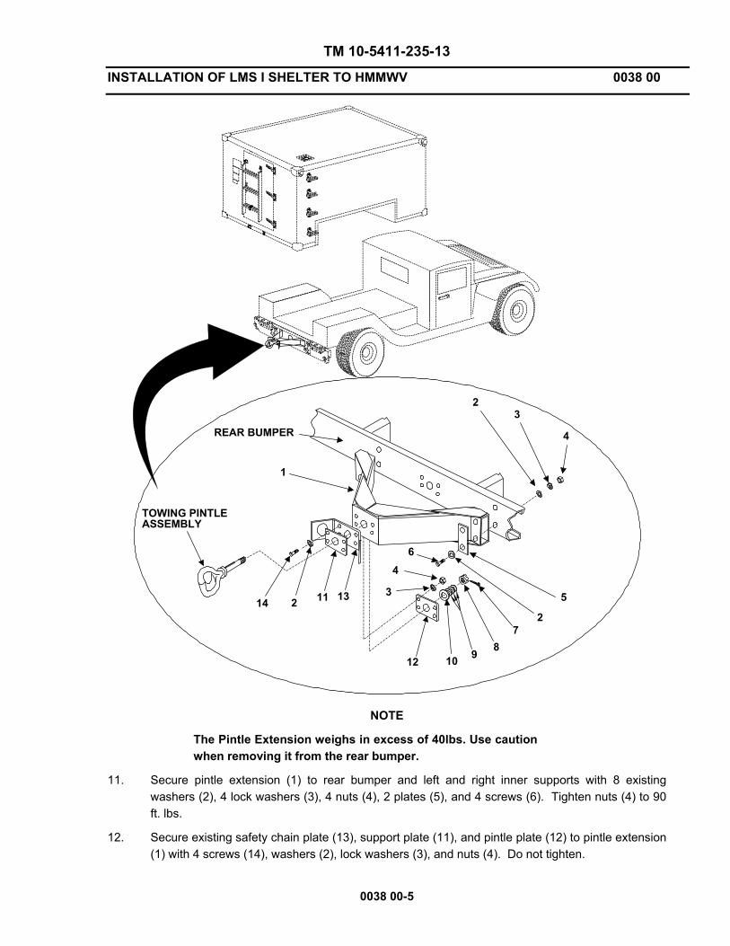
TM 10-5411-235-13
INSTALLATION OF LMS I SHELTER TO HMMWV 0038 00
0038 00-5
23
4
5
7891012
6
1314
REAR BUMPER
22 11
4
3
TOWING PINTLEASSEMBLY
1
NOTE
The Pintle Extension weighs in excess of 40lbs. Use caution when removing it from the rear bumper.
11. Secure pintle extension (1) to rear bumper and left and right inner supports with 8 existing washers (2), 4 lock washers (3), 4 nuts (4), 2 plates (5), and 4 screws (6). Tighten nuts (4) to 90 ft. lbs.
12. Secure existing safety chain plate (13), support plate (11), and pintle plate (12) to pintle extension (1) with 4 screws (14), washers (2), lock washers (3), and nuts (4). Do not tighten.

TM 10-5411-235-13
INSTALLATION OF LMS I SHELTER TO HMMWV 0038 00
0038 00-6
13. Apply a thin coat of MIL-G-10924 grease to shank of towing pintle assembly.
14. Secure towing pintle assembly to pintle extension (1) with existing washer (10), 3 washers (9), existing nut (8), and cotter pin (7). NOTE: Do not overtighten nut; ensure pintle assembly rotates freely when turned by hand.
15. Tighten nuts (4) installed in step 12 to 90 ft. lbs.
REAR SHELTER PREPARATION
WARNING
Be sure shelter is properly positioned on support stands capable of supporting 2000 lbs. Failure to observe safety procedures when working under the shelter could result in severe injury or death.
CAUTION
Do not use excessive force when tightening nuts. Damage to the equipment can occur.
NOTE
During procedure, threaded holes may be fouled with paint/primer/sealer preventing full insertion of bolts. Should this occur, use a bottom tap to clean foreign matter from holes.

TM 10-5411-235-13
INSTALLATION OF LMS I SHELTER TO HMMWV 0038 00
0038 00-7
19
20
262822 21
VIEW A
18
1113
15 17 2
12
1314
16
4
5 6
8
SHELTERREAR CORNER
2729
24
2628
25
1
79
10
BUMPER
VIEW A
26
28
23
103
1. Secure clamping bracket and shim (1) to rear mounting bracket (2) using screw (3), flat washer (4), lock washer (5), and nut (6). Do not tighten.
2. Remove nuts (7), bolts (8), lock washers (9), and flat washers (10) securing curbside rear bumper to vehicle frame. Retain nuts (7), lock washers (9), and flat washers (10).
3. Position and secure rear mounting bracket (2) to rear bumper using (new) longer bolts (8) and flat washers (10), lock washers (9) and nuts (7). Do not tighten bolts.
4. Locate tail light mounting bracket (11) with tail light (12) to rear mounting bracket (2) and secure with flat washers (13), lock washer (14), screw (15), and nut (16).
5. Insert tail light wiring connectors through hole in rear mounting bracket (2), across top of rear bumper and reconnect to vehicle wiring harness. Install grommet (17) in hole in rear mounting bracket (2).
6. On the bottom of the shelter, remove all paint and sealer from any rivet head that may come into contact with rear mounting adapter (18). Remove any bolts/plugs from the bottom rear surface of the shelter.
7. Insert an isolator mounting screw (19), flat washer (20), and isolator mount washers (21) down through each round opening in the rear mounting adapter (18).
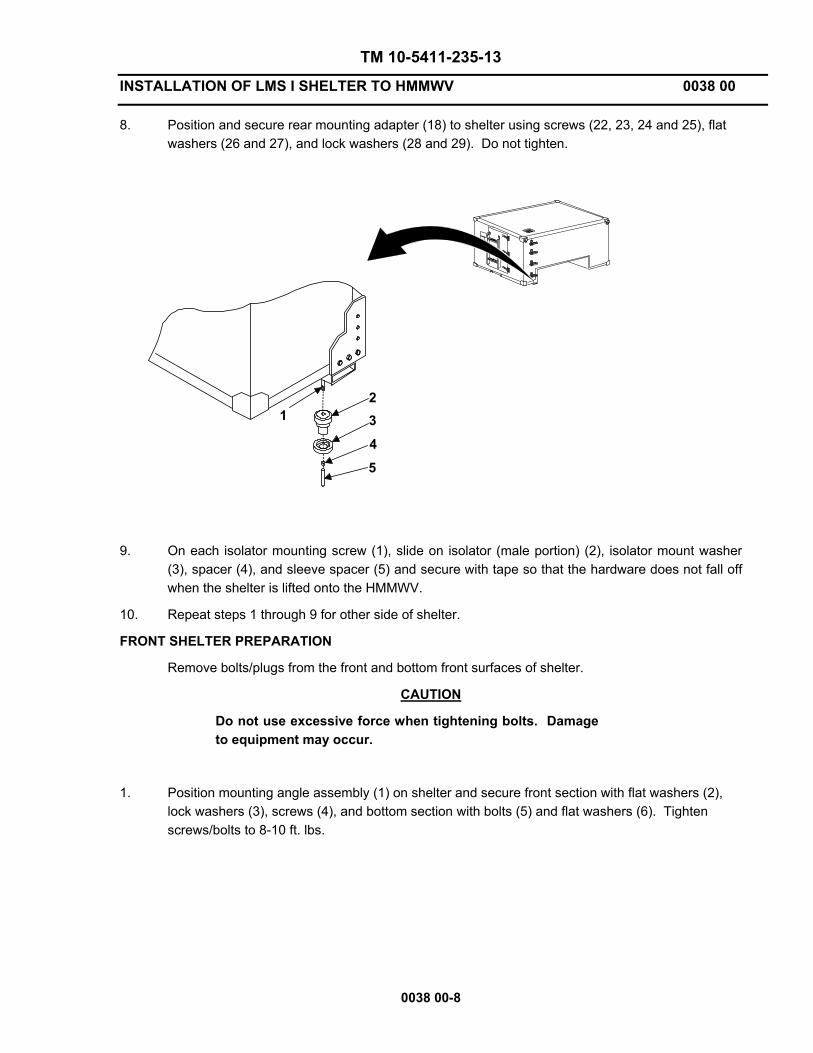
TM 10-5411-235-13
INSTALLATION OF LMS I SHELTER TO HMMWV 0038 00
0038 00-8
8. Position and secure rear mounting adapter (18) to shelter using screws (22, 23, 24 and 25), flat washers (26 and 27), and lock washers (28 and 29). Do not tighten.
1
5432
9. On each isolator mounting screw (1), slide on isolator (male portion) (2), isolator mount washer
(3), spacer (4), and sleeve spacer (5) and secure with tape so that the hardware does not fall off when the shelter is lifted onto the HMMWV.
10. Repeat steps 1 through 9 for other side of shelter.
FRONT SHELTER PREPARATION
Remove bolts/plugs from the front and bottom front surfaces of shelter.
CAUTION
Do not use excessive force when tightening bolts. Damage to equipment may occur.
1. Position mounting angle assembly (1) on shelter and secure front section with flat washers (2), lock washers (3), screws (4), and bottom section with bolts (5) and flat washers (6). Tighten screws/bolts to 8-10 ft. lbs.
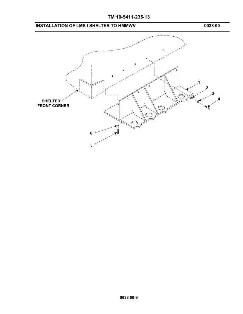
TM 10-5411-235-13
INSTALLATION OF LMS I SHELTER TO HMMWV 0038 00
0038 00-9
SHELTERFRONT CORNER
6
5
43
21
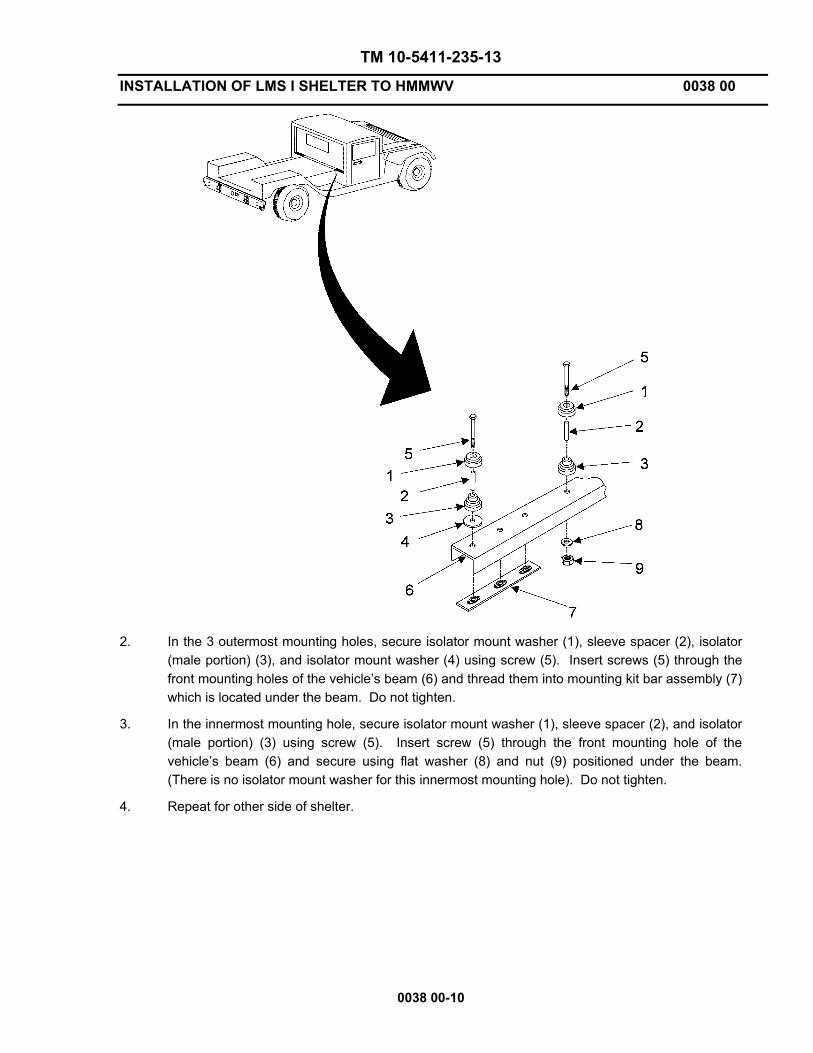
TM 10-5411-235-13
INSTALLATION OF LMS I SHELTER TO HMMWV 0038 00
0038 00-10
2. In the 3 outermost mounting holes, secure isolator mount washer (1), sleeve spacer (2), isolator
(male portion) (3), and isolator mount washer (4) using screw (5). Insert screws (5) through the front mounting holes of the vehicle’s beam (6) and thread them into mounting kit bar assembly (7) which is located under the beam. Do not tighten.
3. In the innermost mounting hole, secure isolator mount washer (1), sleeve spacer (2), and isolator (male portion) (3) using screw (5). Insert screw (5) through the front mounting hole of the vehicle’s beam (6) and secure using flat washer (8) and nut (9) positioned under the beam. (There is no isolator mount washer for this innermost mounting hole). Do not tighten.
4. Repeat for other side of shelter.
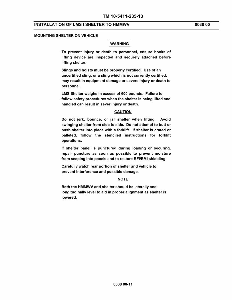
TM 10-5411-235-13
INSTALLATION OF LMS I SHELTER TO HMMWV 0038 00
0038 00-11
MOUNTING SHELTER ON VEHICLE
WARNING
To prevent injury or death to personnel, ensure hooks of lifting device are inspected and securely attached before lifting shelter.
Slings and hoists must be properly certified. Use of an uncertified sling, or a sling which is not currently certified, may result in equipment damage or severe injury or death to personnel.
LMS Shelter weighs in excess of 600 pounds. Failure to follow safety procedures when the shelter is being lifted and handled can result in sever injury or death.
CAUTION
Do not jerk, bounce, or jar shelter when lifting. Avoid swinging shelter from side to side. Do not attempt to butt or push shelter into place with a forklift. If shelter is crated or palleted, follow the stenciled instructions for forklift operations.
If shelter panel is punctured during loading or securing, repair puncture as soon as possible to prevent moisture from seeping into panels and to restore RFI/EMI shielding.
Carefully watch rear portion of shelter and vehicle to prevent interference and possible damage.
NOTE
Both the HMMWV and shelter should be laterally and longitudinally level to aid in proper alignment as shelter is lowered.

TM 10-5411-235-13
INSTALLATION OF LMS I SHELTER TO HMMWV 0038 00
0038 00-12
1. Attach certified sling assembly (1) to all four lifting rings (2) on shelter using the four sling
hooks (3) at opposite end of cables from sling assembly lifting ring (4).
2. Insert lifting hook (5) of the lifting device into sling assembly lifting ring (4).
3. Slowly lift the shelter using the lifting device so that the rear isolator mounting screws (6) are located over their respective holes in the rear mounting bracket (7).
4. Slowly lower the shelter so that the front isolator mounting holes are located slightly above the isolators (8) that are positioned on the vehicle beam (9).

TM 10-5411-235-13
INSTALLATION OF LMS I SHELTER TO HMMWV 0038 00
0038 00-13/(14 Blank)
5. Due to potential variations in the HMMWV or shelter length and width, carefully align each isolator mounting screw (6) with holes on rear mounting bracket (7). Using the slotted holes in the respective pieces, adjust the rear mounting bracket (7) for any lateral movement required and the mounting adapter (10) for any longitudinal movement required.
6. Tighten all screws securing the rear mounting bracket (7) to the rear bumper and rear mounting adapter (10) to the bottom and sides of the shelter.
7. Repeat for the other side of shelter.
8. Slowly lower the shelter onto the HMMWV while maintaining alignment. For each isolator mounting screw (6), remove the tape and slide on 2 isolators (female portion) (11), isolator mount washer (12), and flat washer (13) then secure with self-locking nut (14). Do not tighten.
9. Repeat for the other side of shelter.
CAUTION
Do not use excessive force when tightening bolts. Damage to equipment may occur.
10. Remove each front mounting screw (1) from the vehicle beam and add flat washer (2), isolator mount washer (3), and isolator (female portion) (4) then reattach screw (1).
11. Repeat for the other side of shelter.
12. Once all hardware is installed, recheck and tighten all (front and rear) isolator mounting screws/nuts to 8-10 ft. lbs.
13. Lower the shelter all the way and remove the lifting sling from the lift rings


TM 10-5411-235-13
ILLUSTRATED LIST OF MANUFACTURED ITEMS 0039 00
0039 00-1/(2 Blank)
SCOPE. This work package includes complete instructions for making items authorized to be manufactured or fabricated at Direct Support Maintenance.
GENERAL. A Part Number index in alphanumeric order is provided for cross-referencing the Part Number of the item to be manufactured to the figure which covers fabrication criteria.
Table 1. Part Number Index.
Item Part Number Material Description
SILICONE GASKET 4600292-25 SILICONE RUBBER PER ZZ-R-765, CLASS 3b, GRADE 50, P/N SM-C-654839
RFI SHIELD GASKET 4600293-66 5 CONCENTRIC LAYERS OF TIN COATED COPPER-CLAD STEEL KNITTED WIRE MESH OVER ½ X ½ CLOSED CELL AMS-8195 SILICONE SPONGE CORE, P/N 4600276
NOTES:
ALL DIMENSIONS ARE IN INCHES
WORKMANSHIP IAW MIL-STD-454, REQT 9
END OF WORK PACKAGE


CHAPTER 6
SUPPORTING INFORMATION
FOR THE
LIGHTWEIGHT MULTIPURPOSE SHELTER (LMS)
LMS TYPE 1


TM 10-5411-235-13
REFERENCES 0040 00
0040 00-1
GENERAL
SCOPE. This work package lists all Army regulations, forms, field manuals, technical manuals, and miscellaneous publications referenced in this manual.
FORMS.
DA Form 2028 Recommended Changes to Publications and Blank Forms
DA Form 2028-2 Recommended Changes to Equipment Technical Publications
DA Form 2404 Equipment Inspection and Maintenance Worksheet
DA Form 2407 Maintenance Request
DA Form 2408 Equipment Log Assembly (Records)
DD Form 314 Preventive Maintenance Schedule and Record
DD Form 1397 Processing and Deprocessing Record for Shipment, Storage, and Issue of Vehicle and Spare Parts
SF 364 Report of Discrepancy
SF 368 Product Quality Deficiency Report
TECHNICAL MANUALS.
TM 9-2320-280-10 Operator’s Manual for Truck, Utility, (Cargo/Troop Carrier, 1 – ¼ Ton, 4 X 4), M1097 (2320-01-346-9317)
TM 9-2320-280-10-HR Hand Receipt Manual Covering Contents of Components of End Item (COEI), Basic Issue Items (BII), and Additional Authorization List (AAL) for Truck, Utility, (Cargo/Troop Carrier, 1 – ¼ Ton, 4 X 4), M1097
TM 9-2320-280-20 Unit Maintenance for Truck, Utility, (Cargo/Troop Carrier, 1 – ¼ Ton, 4 X 4), M1097 (Volumes 1, 2, and 3)
TM 9-2320-280-20P Unit Maintenance Repair Parts and Special Tool List for Truck, Utility, (Cargo/Troop Carrier, 1 – ¼ Ton, 4 X 4), M1097
TM 9-2320-280-34 Direct Support and General Support Maintenance for Truck, Utility, (Cargo/Troop Carrier, 1 ¼ Ton, 4 X 4), M1097
TM 9-2320-280-34P Direct Support and General Support Maintenance Repair Parts and Special Tools List for Truck, Utility, (Cargo/Troop Carrier, 1 – ¼ Ton, 4 X 4), M1097
TM 55-2200-001-12 Transportability Guidance for Application of Blocking, Bracing, and Tiedown Materials for Rail Transport
TM 750-244-3 Procedures for Destruction of Equipment to Prevent Enemy Use

TM 10-5411-235-13
REFERENCES 0040 00
0040 00-2
MISCELLANEOUS.
DA PAM 738-750 The Army Maintenance Management System (TAMMS)
LO 9-2320-280-12 Lubrication Order for Truck, Utility, (Cargo/Troop Carrier, 1 – ¼ Ton, 4 X 4), M1097
MIL-G-10924 Military Specification – Grease, Automotive and Artillery
MIL-V-62038 Vehicle Wheeled, Preparation for Shipment and Storage of
SC 5180-90-CL-N26 General Mechanic’s Tool Kit
SB 740-95-1 Storage Serviceability Standards for AMCCOM Materiel
ARMY REGULATIONS.
AR 190-15 Physical Security Program of The Alternate Joint Communications Center
AR 190-51 Security of Unclassified Army Property
AR 220-1 Unit Status Reporting
AR 735-5 Policies and Procedures for Property Accountability
AR 750-1 Army Materiel Maintenance Policy and Retail Maintenance Operations
CTA 50-970 Expendable/Durable Items (Except Medical, Class V, Repair Parts, and Heraldic Items)

TM 10-5411-235-13 GENERAL MAINTENANCE ALLOCATION CHART INFORMATION 0041 00
0041 00-1 Change 1
INTRODUCTION THE ARMY MAINTENANCE SYSTEM MAC This introduction provides a general explanation of all maintenance and repair functions authorized at the two maintenance levels under the Two-Level Maintenance System concept. This MAC (immediately following the introduction) designates overall authority and responsibility for the performance of maintenance functions on the identified end item or component. The application of the maintenance functions to the end item or component shall be consistent with the capacities and capabilities of the designated maintenance levels, which are shown on the MAC in column (4) as:
Field - includes two columns, Unit maintenance and Direct Support maintenance. The Unit maintenance column is divided again into two more subcolumns, C for Operator or Crew and O for Unit maintenance.
Sustainment – includes two subcolumns, General Support (H) and Depot (D).
The tools and test equipment requirements (immediately following the MAC) list the tools and test equipment (both special tools and common tool sets) required for each maintenance function as referenced from the MAC. The remarks (immediately following the tools and test equipment requirements) contain supplemental instructions and explanatory notes for a particular maintenance function. MAINTENANCE FUNCTIONS Maintenance functions are limited to and defined as follows: 1. Inspect. To determine the serviceability of an item by comparing its physical, mechanical, and/or
electrical characteristics with established standards through examination (e.g., by sight, sound, or feel.) This includes scheduled inspection and gagings and evaluation of cannon tubes.
2. Test. To verify serviceability by measuring the mechanical, pneumatic, hydraulic, or electrical characteristics of an item and comparing those characteristics with prescribed standards on a scheduled basis, i.e., load testing of lift devices and hydrostatic testing of pressure hoses.
3. Service. Operations required periodically to keep an item in proper operating condition; e.g., to clean (includes decontaminate, when required), to preserve, to drain, to paint, or to replenish fuel, lubricants, chemical fluids, or gases. This includes scheduled exercising and purging of recoil mechanisms. The following are examples of service functions:
a. Unpack. To remove from packing box for service or when required for the performance of
maintenance operations. b. Repack. To return item to packing box after service and other maintenance operations. c. Clean. To rid the item of contamination. d. Touch up. To spot paint scratched or blistered surfaces.

TM 10-5411-235-13 GENERAL MAINTENANCE ALLOCATION CHART INFORMATION 0041 00
Change 1 0041 00-2
e. Mark. To restore obliterated identification. 4. Adjust. To maintain or regulate, within prescribed limits, by bringing into proper position, or by setting
the operating characteristics to specified parameters. 5. Align. To adjust specified variable elements of an item to bring about optimum or desired performance 6. Calibrate. To determine and cause corrections to be made or to be adjusted on instruments of test,
measuring, and diagnostic equipment used in precision measurement. Consists of comparisons of two instruments, one of which is a certified standard of known accuracy, to detect and adjust any discrepancy in the accuracy of the instrument being compared.
7. Remove/Install. To remove and install the same item when required to perform service or other
maintenance functions. Install may be the act of emplacing, seating, or fixing into position a spare, repair part, or module (component or assembly) in a manner to allow the proper functioning of an equipment or system.
8. Paint. To prepare and spray color coats of paint so that the ammunition can be identified and
protected. The color indicating primary use is applied, preferably, to the entire exterior surface as the background color of the item. Other markings are to be repainted as original so as to retain proper ammunition identification.
9. Replace. To remove an unserviceable item and install a serviceable counterpart in its place. “Replace”
is authorized by the MAC and assigned maintenance level is shown as the third position code of the Source, Maintenance and Recoverability (SMR) code.
10. Repair. The application of maintenance services, including fault location/troubleshooting,
removal/installation, disassembly/assembly procedures and maintenance actions to identify troubles and restore serviceability to an item by correcting specific damage, fault, malfunction, or failure in a part, subassembly, module (component or assembly), end item, or system.
NOTE
The following definitions are applicable to the “repair” maintenance function: Services. Inspect, test, service, adjust, align, calibrate, and/or replace. Fault location/troubleshooting. The process of investigating and detecting the cause of equipment malfunctioning; the act of isolating a fault within a system or Unit Under Test (UUT). Disassembly/assembly. The step-by-step breakdown (taking apart) of a spare/functional group coded item to the level of its least component, that is assigned an SMR code for the level of maintenance under consideration (i.e., identified as maintenance significant). Actions. Welding, grinding, riveting, straightening, facing, machining, and/or resurfacing.
TM 10-5411-235-13 GENERAL MAINTENANCE ALLOCATION CHART INFORMATION 0041 00
0041 00-3 Change 1
11. Overhaul. That maintenance effort (service/action) prescribed to restore an item to a completely
serviceable/operational condition as required by maintenance standards in appropriate technical publications. Overhaul is normally the highest degree of maintenance performed by the Army. Overhaul does not normally return an item to like new condition.
12. Rebuild. Consists of those services/actions necessary for the restoration of unserviceable equipment to a like new condition in accordance with original manufacturing standards. Rebuild is the highest degree of material maintenance applied to Army equipment. The rebuild operation includes the act of returning to zero those age measurements (e.g., hours/miles) considered in classifying Army equipment/components.
EXPLANATION OF COLUMNS IN THE MAC Column (1) Group Number. Column (1) lists Functional Group Code (FGC) numbers, the purpose of which is to identify maintenance significant components, assemblies, subassemblies, and modules with the Next Higher Assembly (NHA). Column (2) Component/Assembly. Column (2) contains the names of components, assemblies, subassemblies, and modules for which maintenance is authorized. Column (3) Maintenance Function. Column (3) lists the functions to be performed on the item listed in column (2). (For a detailed explanation of these functions refer to “Maintenance Functions” outlined above). Column (4) Maintenance Level. Column (4) specifies each level of maintenance authorized to perform each function listed in column (3), by indicating work time required (expressed as manhours in whole hours or decimals) in the appropriate subcolumn. This work time figure represents the active time required to perform that maintenance function at the indicated level of maintenance. If the number or complexity of the tasks within the listed maintenance function varies at different maintenance levels, appropriate work time figures are to be shown for each level. The work time figure represents the average time required to restore an item (assembly, subassembly, component, module, end item, or system) to a serviceable condition under typical field operating conditions. This time includes preparation time (including any necessary disassembly/assembly time), troubleshooting/fault location time, and quality assurance time in addition to the time required to perform the specific tasks identified for the maintenance functions authorized in the MAC. The system designations for the various maintenance levels are as follows: Field:
Sustainment:
C Operator or Crew maintenance O Unit maintenance F Direct Support maintenance
L Specialized Repair Activity H General Support maintenance D Depot maintenance
TM 10-5411-235-13 GENERAL MAINTENANCE ALLOCATION CHART INFORMATION 0041 00
Change 1 0041 00-4
NOTE The “L” maintenance level is not included in column (4) of the MAC. Functions to this level of maintenance are identified by work time figure in the “H” column of column (4), and an associated reference code is used in the REMARKS column (6). This code is keyed to the remarks and the SRA complete repair application is explained there.
Column (5) Tools and Equipment Reference Code. Column (5) specifies, by code, those common tool sets (not individual tools), common Test, Measurement and Diagnostic Equipment (TMDE), and special tools, special TMDE and special support equipment required to perform the designated function. Codes are keyed to the entries in the tools and test equipment table. Column (6) Remarks Code. When applicable, this column contains a letter code, in alphabetic order, which is keyed to the remarks table entries. EXPLANATION OF COLUMNS IN THE TOOLS AND TEST EQUIPMENT REQUIREMENTS Column (1) - Tool or Test Equipment Reference Code. The tool or test equipment reference code correlates with a code used in column (5) of the MAC. Column (2) - Maintenance Level. The lowest level of maintenance authorized to use the tool or test equipment. Column (3) - Nomenclature. Name or identification of tool or test equipment. Column (4) - National Stock Number (NSN). The NSN of the tool or test equipment. Column (5) - Tool Number. The manufacturer’s part number. EXPLANATION OF COLUMNS IN REMARKS Column (1) - Remarks Code. The code recorded in column (6) of the MAC. Column (2) - Remarks. This column lists information pertinent to the maintenance function being performed as indicated in the MAC.

TM 10-5411-235-13 GENERAL MAINTENANCE ALLOCATION CHART (MAC) 0042 00
0042 00-1 Change 1
Table 1. MAC for LMS I
(4)
MAINTENANCE LEVEL
FIELD SUSTAINMENT
UNIT DIRECT SUPPORT
GENERAL SUPPORT
DEPOT
(1)
GROUP NUMBER
(2)
COMPONENT/ ASSEMBLY
(3)
MAINTENANCE FUNCTION
C O F H D
(5)
TOOLS AND EQUIPMENT REFERENCE
CODE
(6)
REMARKS CODE
00 Service 0.1 Install 0.6
LIGHTWEIGHT MULTI-PURPOSE SHELTER (LMS TYPE 1)
01 Replace 0.1 1
SHELTER ASSEMBLY
02 Replace 0.2 1
HANDHOLD ASSEMBLY
03 Replace 0.2 1
SHELTER ASSEMBLIES
04 Replace 0.1 1
DEPLOYED LADDER BRACKET ASSEMBLIES
05 Replace 0.1
LADDER ASSEMBLY
0501 Inspect 0.1 1
LADDER STRAP ASSEMBLY Replace 0.2
06 Replace 0.8 1 Test 0.2
DOOR ASSEMBLY
Adjust 0.6 0601 RFI/EMI GASKETS Replace 0.1 1 0602 Replace 0.2 1
DOOR BRACE ASSEMBLY
0603 Replace 0.4 1
ROLLER LATCH ASSEMBLY
0604 Replace 0.3 1
PERSONNEL DOOR HINGE

TM 10-5411-235-13 GENERAL MAINTENANCE ALLOCATION CHART (MAC) 0042 00
Change 1 0042 00-2
Table 1. MAC for LMS I - continued
(4)
MAINTENANCE LEVEL FIELD SUSTAINMENT
UNIT DIRECT SUPPORT
GENERAL SUPPORT
DEPOT
(1)
GROUP NUMBER
(2)
COMPONENT/ ASSEMBLY
(3)
MAINTENANCE FUNCTION
C O F H D
(5)
TOOLS AND EQUIPMENT REFERENCE
CODE
(6)
REMARKS CODE
07 SHELTER PANEL (SHELTER DENT) Repair 0.3 1,7 Repair 0.5 1,2,4,7
(PUNCTURE-NO CORE DAMAGE)
Repair 0.1 1,2,4,7,8
(PUNCTURE-DAMAGE TO CORE)
Inspect 0.1 Repair 1.0 1,2,3,4,6 A
(DELAMINATION)
08 Replace 0.2 1,2,4
LIFTING RING BUMPER
09 Replace 0.3 2,4
SHELTER DRIP MOLDING
010 Replace 0.3 1,2,4
STOWED LADDER BRACKETS
011 FLOOR DRAIN
PLUG Replace 0.2 2,4

TM 10-5411-235-13 GENERAL MAINTENANCE ALLOCATION CHART (MAC) 0042 00
0042 00-3/(4 Blank) Change 1
Table 2. Tools and Test Equipment for LMS 1
(1) TOOL OR TEST
EQUIPMENT REFERENCE
CODE
(2) MAINTENANCE
LEVEL
(3) NOMENCLATURE
(4) NATIONAL
STOCK NUMBER
(5) TOOL
NUMBER
01 OF General Mechanics Tool Kit 5180-00-177-7033
02 OF Riveting Tool 5120-00-177-9839
03 OF Tapping Hammer 5120-00-293-1155
04 OF Drill 5133-00-227-9667
05 OF Rosan Insert/Removal Tool 5180-00-330-5076
06 OF Caulking Gun 5120-00-293-0478
07 F Oscillating Sander 5130-00-606-9694
08 F Circular Saw 5130-00-490-1380
Table 3. Remarks for LMS 1
(1) REMARKS
CODE
(2) REMARKS
A Time reflected in column F (DS) does not include time (12 hours) to allow the adhesive to cure, REF WP 0038 00, Repair, line #10.


TM 10-5411-235-13
COMPONENTS OF END ITEM (COEI) AND BASIC ISSUE(BII) ITEMS LISTS 0043 00
0043 00-1
INTRODUCTION
SCOPE. This work package lists COEI and BII for the Lightweight Multi-purpose Shelter (LMS Type 1) to help you inventory items required for safe and efficient operation of the equipment.
GENERAL. The COEI and BII Lists are divided into the following lists:
Components of End Item. This listing is for informational purposes only, and is not authority to requisition replacements. These items are part of the end item, but are removed and separately packaged for transportation or shipment. As part of the end item, these items must be with the end item whenever it is issued or transferred between property accounts. Illustrations are furnished to assist you in identifying the items.
Basic Issue Items. These are minimum essential items required to place the Lightweight Multi-purpose Shelter (LMS Type 1) in operation, to operate it, and to perform emergency repairs. Although shipped separately packaged, BII must be with the Lightweight Multi-purpose Shelter (LMS Type 1) during operation and whenever it is transferred between property accounts. The illustrations will assist you with hard to identify items. This manual is your authority to request/requisition replacement BII, based on TOE/MTOE authorization of the end item.
EXPLANATION OF COLUMNS. The following provides an explanation of columns found in the tabular listing:
Column (1) - Illustration Number. This column indicates the number of the illustration in which the item is shown.
Column (2) - National Stock Number. Indicates the National Stock Number assigned to the item and will be used for requisitioning purposes.
Column (3) - Description and Usable On Code. Indicates the Federal Item Name and, if required, a minimum description to identify and locate the item. The last line for each item indicates the CAGE (in parentheses) followed by the Part Number.
Column (4)- Unit of Measure (U/M). Indicates the physical measurement or count of the item as issued per the National Stock Number shown in column 2.
Column (5) - Quantity Required (QTY Rqd). Indicates the quantity of the item required to be used with/on the equipment.

TM 10-5411-235-13
COMPONENTS OF END ITEM (COEI) AND BASIC ISSUE ITEMS (BII) LISTS 0043 00
0043 00-2
Table 1. Components of End Item List.
(1) ILLUS
NUMBER
(2) NATIONAL STOCK
NUMBER
(3) DESCRIPTION, CAGEC, AND
PART NUMBER
(4)
USABLE ON CODE
(5) U/M
(6)
QTY
RQR
1 5411-01-473-5051 Lightweight Multipurpose Shelter (LMS) Type 1
EA 1
2 N/A Ladder Assembly (Stored on door, deployed below door)
EA 1
*The packing list and accompanying illustrations should be retained with the LMS for future use or for transfer between property accounts.
2 1
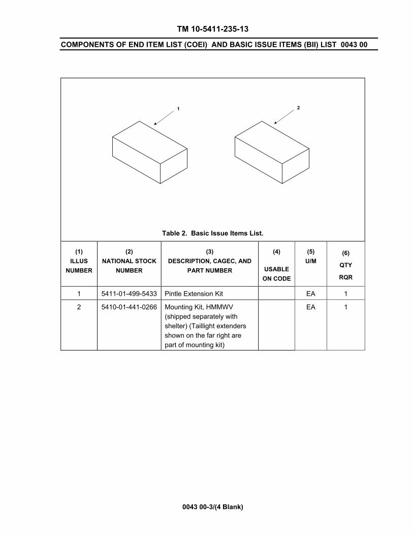
TM 10-5411-235-13
COMPONENTS OF END ITEM LIST (COEI) AND BASIC ISSUE ITEMS (BII) LIST 0043 00
0043 00-3/(4 Blank)
Table 2. Basic Issue Items List.
(1) ILLUS
NUMBER
(2) NATIONAL STOCK
NUMBER
(3) DESCRIPTION, CAGEC, AND
PART NUMBER
(4)
USABLE ON CODE
(5) U/M
(6)
QTY
RQR
1 5411-01-499-5433 Pintle Extension Kit EA 1
2 5410-01-441-0266 Mounting Kit, HMMWV (shipped separately with shelter) (Taillight extenders shown on the far right are part of mounting kit)
EA 1
1 2

TM 10-5411-235-13
INTRODUCTION 0044 00
0044 00-1
INTRODUCTION
SCOPE. This work package lists expendable supplies and materials you will need to operate and maintain the Lightweight Multi-purpose Shelter (LMS Type 1). This List is for your information only and is not authority to requisition the listed items. These items are authorized to you by CTA 50-970, Expendable/Durable Items (except Medical, Class V, Repair Parts and Heraldic Items), or CTA 8-100, Army Medical Department Expendable/Durable Items.
EXPLANATION OF COLUMNS.
Column (1) - Item Number. This number is assigned to the entry in the list and is referenced in the narrative instructions to identify the item (e.g., clean all parts with a lint-free cotton cloth (WP 0044, Table 1, Item 3).
Column (2) - Level. This column indicates the lowest level of maintenance that required the listed item (C=Operator/Crew).
C - Operator/Crew O - Unit/Organization Maintenance F - Direct Support Maintenance D - Depot Maintenance
Column (3) - National Stock Number. This is the NSN assigned to the item which you can use to requisition it.
Column (4) – Item Name, Description, Commercial and Government Entity Code (CAGE), and Part Number (P/N). This column provides the other information you need to identify the item.
Column (5) - Unit of Measure (U/M). This code shows the physical measurement or count of an item, such as gallon, dozen, gross, etc.

TM 10-5411-235-13
EXPENDABLE AND DURABLE SUPPLIES AND MATERIALS LIST 0044 00
0044 00-2
Table 1. Expendable/Durable Supplies and Materials List.
(1) Item
Number
(2) Level
(3) National Stock
Number
(4) Item Name,Description, CAGE, Part Number
(5) U/M
1 C 9158-00-759-0014 Lubricant, Solid Film, MIL-L-23398 AR
2 F Polysulfide Sealer GL
3 C 6850-00-948-5853 Cloth, Cotton AR
4 F 8040-00-078-9774 Adhesive GL
5 F 7830-00-884-4014 Chalk AR
6 F Polyethylene Wrap SH
7 F 6810-00-286-5435 Alcohol, Isopropyl GL
8 F Commercial Body Filler GL
9 F Core, Honeycomb AR
10 F Fiber Filled Polyester Resin GL
11 F 8415-00-009-1900 Gloves, Rubber PR 12 F 5350-00-161-9043 Sandpaper SH
13 F Aluminum, QQ-A-250, 6061-T6, .042" AR
14 F Caulking Cartridge EA
15 F Container, Unwaxed EA
16 F 8040-00-222-9059 Epoxy Resin (Versimid 140) GL
17 F 8040-01-197-0228 Epoxy Resin (EPIC R1003) GL
18 F 5320-00-956-7355 Rivet, Domed Head, Pop, 07707, AD64H EA
19 F 8030-01-136-8953 Sealer, 81337, SM-B-563756 AR
20 O 5310-00-933-8120 Lockwasher, 96906, MS35338-138 EA
21 O 5310-00-592-5965 Lockwasher, 96906, MS35338-44 EA
22 O 5315-01-359-1451 Cotter Pin, 96906, MS24665-285 EA
23 O Shim, 81337, 17-1-3566-3 EA
24 O 5310-01-338-7338 Lockwasher, 96906, MS35338-45 EA
25 O 5310-01-249-9376 Lockwasher, 96906, MS35338-139 EA
26 O 5310-00-929-6395 Lockwasher, 96906, MS35338-136 EA
27 F 5320-00-882-3375 Rivet, Domed Head, Pop, 07707, AD66H EA
28 F 5320-01-032-6534 Rivet, Domed Head, Pop, 07707, AD68H EA
29 F 5320-01-210-7955 Fastener, Blind, 96906, MS90354U0603 EA

TM 10-5411-235-13
EXPENDABLE AND DURABLE SUPPLIES AND MATERIALS LIST 0044 00
0044 00-3/(4 Blank)
30 F Sealer, Conductive, 81337, 17-1-5706-1 AR
31 F 5320-01-295-9924 Rivet, Domed Head, Pop, 07707, AD42H EA
32 F Adhesive, 96906, M4610611DWI AR
33 F 8010-00-171-1518 Primer Coating, (81349) MIL-P-11414 PT
34 C 9150-00-826-2740 Lubricant Oil, (81349) MIL-L-2104 QT 35 F 4240-00-052-3776 Safety Goggles EA


Distribution: To be distributed in accordance with Initial Distribution Number (IDN) 256188 requirements for TM 10-5411-235-13.
By Order of the Secretary of the Army:
PETER J. SCHOOMAKERGeneral, United States Army
Chief of Staff Official:
JOEL B. HUDSON Administrative Assistant to the
Secretary of the Army 0318406


These are the instructions for sending an electronic 2028The following format must be used if submitting an electronic 2028. The subject line must be exactly thesame and all fields must be included; however only the following fields are mandatory: 1, 3, 4, 5, 6, 7, 8,9, 10, 13, 15, 16, 17, and 27.
From: “Whomever” <[email protected]>To : a ms s b riml @ n a t ic k . a rmy. mil
Subject: DA Form 20281. From: Joe Smith2. Unit: home3. Address: 4300 Park4. City: Hometown5. St: MO6. Zip: 777777. Date Sent: 19--OCT--938. Pub no: 55--2840--229--239. Pub Title: TM10. Publication Date: 04--JUL--8511. Change Number: 712. Submitter Rank: MSG13. Submitter FName: Joe14. Submitter MName: T15. Submitter LName: Smith16. Submitter Phone: 123--123--123417. Problem: 118. Page: 219. Paragraph: 320. Line: 421. NSN: 522. Reference: 623. Figure: 724. Table: 825. Item: 926. Total: 12327. Text:This is the text for the problem below line 27.

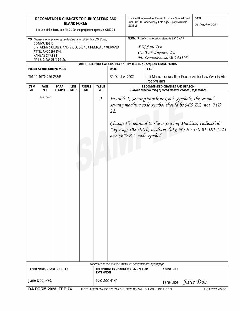
RECOMMENDED CHANGES TO PUBLICATIONS AND BLANK FORMS
For use of this form, see AR 25-30; the proponent agency is ODISC4.
Use Part II (reverse) for Repair Parts and Special Tool Lists (RPSTL) and Supply Catalogs/Supply Manuals (SC/SM).
DATE
21 October 2003
TO: (Forward to proponent of publication or form) (Include ZIP Code) COMMANDER U.S. ARMY SOLDIER AND BIOLOGICAL CHEMICAL COMMAND ATTN: AMSSB-RIM-L KANSAS STREET NATICK, MA 01760-5052
FROM: (Activity and location) (Include ZIP Code) PFC Jane Doe CO A 3rd Engineer BR Ft. Leonardwood, MO 63108
PART I – ALL PUBLICATIONS (EXCEPT RPSTL AND SC/SM) AND BLANK FORMS PUBLICATION/FORM NUMBER TM 10-1670-296-23&P
DATE 30 October 2002
TITLE Unit Manual for Ancillary Equipment for Low Velocity Air Drop Systems
ITEM NO.
PAGE NO.
PARA- GRAPH
LINE NO. *
FIGURE NO.
TABLE NO.
RECOMMENDED CHANGES AND REASON (Provide exact wording of recommended changes, if possible).
0036 00-2
1
In table 1, Sewing Machine Code Symbols, the second sewing machine code symbol should be MD ZZ not MD 22. Change the manual to show Sewing Machine, Industrial: Zig-Zag; 308 stitch; medium-duty; NSN 3530-01-181-1421 as a MD ZZ code symbol.
*Reference to line numbers within the paragraph or subparagraph. TYPED NAME, GRADE OR TITLE Jane Doe, PFC
TELEPHONE EXCHANGE/AUTOVON, PLUS EXTENSION 508-233-4141
SIGNATURE
Jane Doe Jane Doe
DA FORM 2028, FEB 74 REPLACES DA FORM 2028, 1 DEC 68, WHICH WILL BE USED. USAPPC V3.00
TO: (Forward direct to addressee listed in publication) COMMANDER U.S. ARMY SOLDIER AND BIOLOGICAL CHEMICAL COMMAND ATTN: AMSSB-RIM-L KANSAS STREET NATICK, MA 01760-5052
FROM: (Activity and location) (Include ZIP Code) PFC Jane Doe CO A 3rd Engineer BR Ft. Leonardwood, MO 63108
DATE 21 October 2003
PART II – REPAIR PARTS AND SPECIAL TOOL LISTS AND SUPPLY CATALOGS/SUPPLY MANUALS PUBLICATION NUMBER TM 10-1670-296-23&P
DATE 30 October 2002
TITLE Unit Manual for Ancillary Equipment for Low Velocity Air Drop Systems
PAGE NO.
COLM
NO.
LINE NO.
NATIONAL
STOCK NUMBER
REFERENCE
NO.
FIGURE
NO.
ITEM NO.
TOTAL NO. OF MAJOR ITEMS SUPPORTED
RECOMMENDED ACTION 0066 00-1
4
Callout 16 in figure 4 is pointed to a D-Ring. In the Repair Parts List key for figure 4, item 16 is called a Snap Hook. Please correct one or the other.
PART III – REMARKS (Any general remarks or recommendations, or suggestions for improvement of publications and blank forms. Additional blank sheets may be used if more space is needed.)
TYPED NAME, GRADE OR TITLE
TELEPHONE EXCHANGE/AUTOVON, PLUS EXTENSION
SIGNATURE
UASPPC V3.00

RECOMMENDED CHANGES TO PUBLICATIONS AND BLANK FORMS
For use of this form, see AR 25-30; the proponent agency is ODISC4.
Use Part II (reverse) for Repair Parts and Special Tool Lists (RPSTL) and Supply Catalogs/Supply Manuals (SC/SM).
DATE
TO: (Forward to proponent of publication or form) (Include ZIP Code) COMMANDER U.S. ARMY TANK-AUTOMOTIVE AND ARMAMENT COMMAND ATTN: AMSTA-LC-CECT 15 KANSAS STREET NATICK, MA 01760-5052
FROM: (Activity and location) (Include ZIP Code)
PART I – ALL PUBLICATIONS (EXCEPT RPSTL AND SC/SM) AND BLANK FORMS PUBLICATION/FORM NUMBER TM 10-5411-235-13
DATE 31 August 2003
TITLE Operator’s, Unit and Direct Support Maintenance Manual, For Lightweight Multipurpose Shelter (LMS) LMS Type 1
ITEM NO.
PAGE NO.
PARA- GRAPH
LINE NO. *
FIGURE NO.
TABLE NO.
RECOMMENDED CHANGES AND REASON (Provide exact wording of recommended changes, if possible).
*Reference to line numbers within the paragraph or subparagraph. TYPED NAME, GRADE OR TITLE TELEPHONE EXCHANGE/AUTOVON, PLUS
EXTENSION SIGNATURE
DA FORM 2028, FEB 74 REPLACES DA FORM 2028, 1 DEC 68, WHICH WILL BE USED. USAPPC V3.00

TO: (Forward direct to addressee listed in publication) COMMANDER U.S. ARMY TANK-AUTOMOTIVE AND ARMAMENT COMMAND ATTN: AMSTA-LC-CECT 15 KANSAS STREET NATICK, MA 01760-5052
FROM: (Activity and location) (Include ZIP Code) DATE
PART II – REPAIR PARTS AND SPECIAL TOOL LISTS AND SUPPLY CATALOGS/SUPPLY MANUALS PUBLICATION NUMBER TM 10-5411-235-13
DATE 31 August 2003
TITLE Operator’s, Unit and Direct Support Maintenance Manual, For Lightweight Multipurpose Shelter (LMS) LMS Type 1
PAGE NO.
COLM
NO.
LINE NO.
NATIONAL STOCK
NUMBER
REFERENCE
NO.
FIGURE
NO.
ITEM NO.
TOTAL NO. OF MAJOR
ITEMS SUPPORTED
RECOMMENDED ACTION
PART III – REMARKS (Any general remarks or recommendations, or suggestions for improvement of publications and blank forms. Additional blank sheets may be used if more space is needed.)
TYPED NAME, GRADE OR TITLE TELEPHONE EXCHANGE/AUTOVON, PLUS EXTENSION SIGNATURE
UASPPC V3.00

RECOMMENDED CHANGES TO PUBLICATIONS AND BLANK FORMS
For use of this form, see AR 25-30; the proponent agency is ODISC4.
Use Part II (reverse) for Repair Parts and Special Tool Lists (RPSTL) and Supply Catalogs/Supply Manuals (SC/SM).
DATE
TO: (Forward to proponent of publication or form) (Include ZIP Code) COMMANDER U.S. ARMY TANK-AUTOMOTIVE AND ARMAMENT COMMAND ATTN: AMSTA-LC-CECT 15 KANSAS STREET NATICK, MA 01760-5052
FROM: (Activity and location) (Include ZIP Code)
PART I – ALL PUBLICATIONS (EXCEPT RPSTL AND SC/SM) AND BLANK FORMS PUBLICATION/FORM NUMBER TM 10-5411-235-13
DATE 31 August 2003
TITLE Operator’s, Unit and Direct Support Maintenance Manual, For Lightweight Multipurpose Shelter (LMS) LMS Type 1
ITEM NO.
PAGE NO.
PARA- GRAPH
LINE NO. *
FIGURE NO.
TABLE NO.
RECOMMENDED CHANGES AND REASON (Provide exact wording of recommended changes, if possible).
*Reference to line numbers within the paragraph or subparagraph. TYPED NAME, GRADE OR TITLE TELEPHONE EXCHANGE/AUTOVON, PLUS
EXTENSION SIGNATURE
DA FORM 2028, FEB 74 REPLACES DA FORM 2028, 1 DEC 68, WHICH WILL BE USED. USAPPC V3.00
TO: (Forward direct to addressee listed in publication) COMMANDER U.S. ARMY TANK-AUTOMOTIVE AND ARMAMENT COMMAND ATTN: AMSTA-LC-CECT 15 KANSAS STREET NATICK, MA 01760-5052
FROM: (Activity and location) (Include ZIP Code) DATE
PART II – REPAIR PARTS AND SPECIAL TOOL LISTS AND SUPPLY CATALOGS/SUPPLY MANUALS PUBLICATION NUMBER TM 10-5411-235-13
DATE 31 August 2003
TITLE Operator’s, Unit and Direct Support Maintenance Manual, For Lightweight Multipurpose Shelter (LMS) LMS Type 1
PAGE NO.
COLM
NO.
LINE NO.
NATIONAL STOCK
NUMBER
REFERENCE
NO.
FIGURE
NO.
ITEM NO.
TOTAL NO. OF MAJOR
ITEMS SUPPORTED
RECOMMENDED ACTION
PART III – REMARKS (Any general remarks or recommendations, or suggestions for improvement of publications and blank forms. Additional blank sheets may be used if more space is needed.)
TYPED NAME, GRADE OR TITLE TELEPHONE EXCHANGE/AUTOVON, PLUS EXTENSION SIGNATURE
UASPPC V3.00

The Metric System and Equivalents
Linear Measure Liquid Measure1 centimeter = 10 millimeters = .39 inch 1 centiliter = 10 milliliters = .34 fl. ounce1 decimeter = 10 centimeters = 3.94 inches 1 deciliter = 10 centiliters = 3.38 fl. ounces1 meter = 10 decimeters = 39.37 inches 1 liter = 10 deciliters = 33.81 fl. ounces1 dekameter = 10 meters = 32.8 feet 1 dekaliter = 10 liters = 2.64 gallons1 hectometer = 10 dekameters = 328.08 feet 1 hectoliter = 10 dekaliters = 26.42 gallons1 kilometer = 10 hectometers = 3,280.8 feet 1 kiloliter = 10 hectoliters = 264.18 gallons
Weights Square Measure1 centigram = 10 milligrams = .15 grain 1 sq. centimeter = 100 sq. millimeters = .155 sq. inch1 decigram = 10 centigrams = 1.54 grains 1 sq. decimeter = 100 sq. centimeters = 15.5 sq. inches1 gram = 10 decigrams = .035 ounce 1 sq. meter (centare) = 100 sq. decimeters = 10.76 sq. feet1 dekagram = 10 grams = .35 ounce 1 sq. dekameter (are) = 100 sq. meters = 1,076.4 sq. feet1 hectogram = 10 dekagrams = 3.52 ounces 1 sq. hectometer (hectare) = 100 sq. dekameters = 2.47 acres1 kilogram = 10 hectograms = 2.2 pounds 1 sq. kilometer = 100 sq. hectometers = .386 sq. mile1 quintal = 100 kilograms = 220.46 pounds1 metric ton = 10 quintals = 1.1 short tons Cubic Measure
1 cu. centimeter = 1000 cu. millimeters = .06 cu. inch1 cu. decimeter = 1000 cu. centimeters = 61.02 cu. inches1 cu. meter = 1000 cu. decimeters = 35.31 feet
Approximate Conversion Factors
To change To Multiply by To change To Multiply byinches centimeters 2.540 ounce--inches newton--meters .007062feet meters .305 centimeters inches .394yards meters .914 meters feet 3.280miles kilometers 1.609 meters yards 1.094square inches square centimeters 6.451 kilometers miles .621square feet square meters .093 square centimeters square inches .155square yards square meters .836 square meters square feet 10.764square miles square kilometers 2.590 square meters square yards 1.196acres square hectometers .405 square kilometers square miles .386cubic feet cubic meters .028 square hectometers acres 2.471cubic yards cubic meters .765 cubic meters cubic feet 35.315fluid ounces milliliters 29.573 cubic meters cubic yards 1.308pints liters .473 milliliters fluid ounces .034quarts liters .946 liters pints 2.113gallons liters 3.785 liters quarts 1.057ounces grams 28.349 liters gallons .264pounds kilograms .454 grams ounces .035short tons metric tons .907 kilograms pounds 2.205pound--feet newton--meters 1.356 metric tons short tons 1.102pound--inches newton--meters .11296
Temperature (Exact)
_F Fahrenheittemperature
5/9 (aftersubtracting 32)
Celsiustemperature
_C

PIN:080904-000