technical manual operator's manual for · tm 9-6115-642-10 a warning summary first aid for...
TRANSCRIPT
ARMY *TM 9-6115-642-10AIR FORCE TO 35C2-3-455-11MARINE CORPS TM 09247A/09248A-10/1
HEADQUARTERS, DEPARTMENTS OF THE ARMY, AIRFORCE AND HEADQUARTERS, U.S. MARINE CORPS
15 SEPTEMBER 2010 PCN 184 092471 00
TECHNICAL MANUAL
OPERATOR'S MANUALFOR
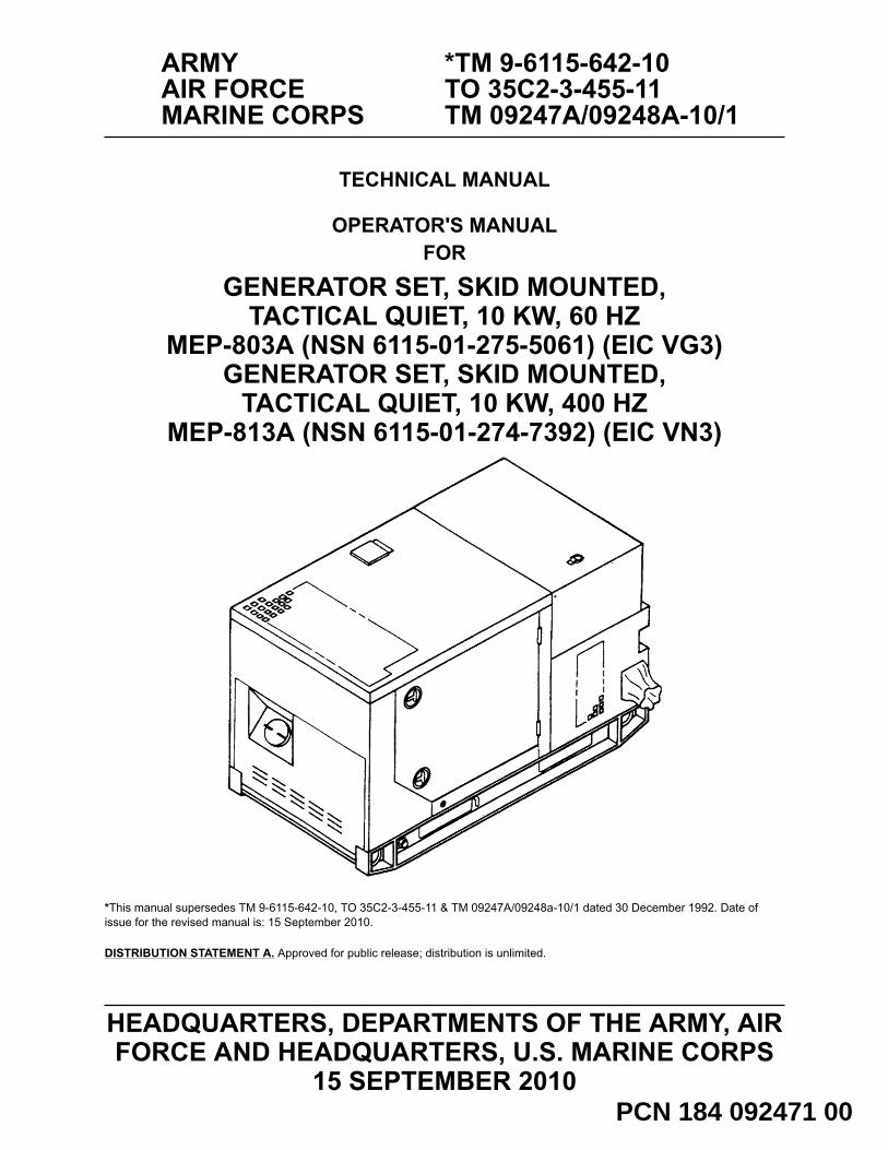
GENERATOR SET, SKID MOUNTED,TACTICAL QUIET, 10 KW, 60 HZ
MEP-803A (NSN 6115-01-275-5061) (EIC VG3)GENERATOR SET, SKID MOUNTED,
TACTICAL QUIET, 10 KW, 400 HZMEP-813A (NSN 6115-01-274-7392) (EIC VN3)
*This manual supersedes TM 9-6115-642-10, TO 35C2-3-455-11 & TM 09247A/09248a-10/1 dated 30 December 1992. Date ofissue for the revised manual is: 15 September 2010.
DISTRIBUTION STATEMENT A. Approved for public release; distribution is unlimited.


TM 9-6115-642-10
a
WARNING SUMMARY
FIRST AID
For First Aid information, refer to FM 4-25.11.
5 SAFETY STEPS TO FOLLOW IF SOMEONE IS THE VICTIM OF ELECTRICALSHOCK:
DO NOT TRY TO PULL OR GRAB THE INDIVIDUAL.
IF POSSIBLE, TURN OFF THE ELECTRICAL POWER.
IF YOU CANNOT TURN OFF THE ELECTRICAL POWER, PULL, PUSH OR LIFTTHE PERSON TO SAFETY USING A DRY WOODEN POLE OR A DRY ROPEOR SOME OTHER INSULATING MATERIAL.
SEND FOR HELP AS SOON AS POSSIBLE.
AFTER THE INJURED PERSON IS FREE OF CONTACT WITH THE SOURCEOF ELECTRICAL SHOCK, MOVE THE PERSON A SHORT DISTANCE AWAYAND IMMEDIATELY START ARTIFICIAL RESUSCITATION.
WARNING AND CAUTION STATEMENTS
Warning and Caution statements have been strategically placed throughout this text prior to operating proce-dures, practices, or conditions considered essential to the protection of personnel (WARNING) or equipment andproperty (CAUTION).
A WARNING or CAUTION will apply each time the related step is repeated. Prior to starting any task the WARN-INGs or CAUTIONs included in the text for that task must be reviewed and understood. Refer to the materials listat the beginning of the appropriate manual section for materials used during maintenance of this equipment. Thiswarning summary contains the WARNINGs included in the manual.

TM 9-6115-642-10
WARNING SUMMARY – CONTINUED
b
WARNINGHigh voltage is produced when this generator set is in operation. Improper operation could result in personal injuryor death by electrocution.
WARNINGNever attempt to start the generator set if it is not properly grounded. Failure to observe this warning could resultin serious injury or death by electrocution.
WARNINGNever attempt to connect or disconnect load cables while the generator is running. Failure to observe this warningcould result in severe personal injury or death by electrocution.
WARNINGJumper will not be removed unless the equipment being powered specifically required an isolated ground (floatingground). Failure to comply with this warning can cause injury or death to personnel.
WARNINGDC voltages are present at generator set electrical components even with generator set shut down. Avoid ground-ing self when touching any electrical components. Failure to observe this warning can result in personal injury.
WARNINGBattery acid will cause burns to unprotected skin.
WARNINGThe fuels in this generator set are highly explosive. Do not smoke or use open flame when performing mainte-nance. Flames and explosion could result in severe personal injury or death.
WARNINGHot fueling of generators while they are operating presents a safety hazard and should not be attempted. Hotengine surfaces and sparks produced from the engine and generator circuitry are possible sources of ignition.Failure to observe this warning could cause severe personal injury or death may result.
WARNINGBatteries give off flammable gas. Do not smoke or use open flame when performing maintenance. Flames andexplosion could result in personal injury or death.
WARNINGExhaust discharge contains deadly gases. Do not operate generator set in enclosed area unless exhaust dis-charge is properly vented outside. Severe personal injury or death due to carbon monoxide poisoning could result.
WARNINGLiquids under pressure are generated as a result of operation of the generator set. High pressure leaks couldcause severe personal injury or death.
TM 9-6115-642-10
WARNING SUMMARY – CONTINUED
c / (d blank)
WARNINGWith any access door open, the noise level of this generator set when operating could cause hearing damage.Hearing protection must be worn when working near the generator set while running.
WARNINGCooling system operates at high temperatures. Personal injury or death from burns or scalding could result fromcontact with high pressure steam and/or liquid.
WARNINGAvoid contacting metal items with bare skin in extreme cold weather. Failure to observe this warning can result inpersonal injury.

TM 9-6115-642-10
A/(B blank) USA
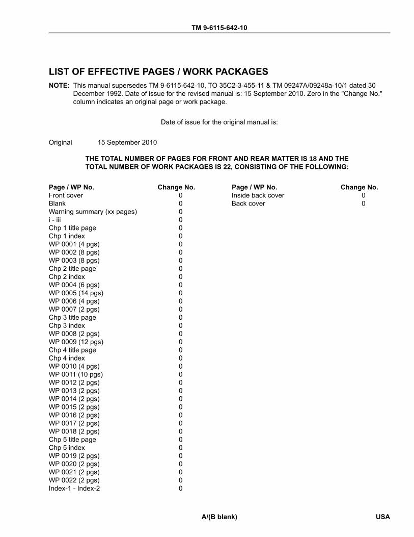
LIST OF EFFECTIVE PAGES / WORK PACKAGESNOTE: This manual supersedes TM 9-6115-642-10, TO 35C2-3-455-11 & TM 09247A/09248a-10/1 dated 30
December 1992. Date of issue for the revised manual is: 15 September 2010. Zero in the "Change No."column indicates an original page or work package.
Date of issue for the original manual is:
Original 15 September 2010
THE TOTAL NUMBER OF PAGES FOR FRONT AND REAR MATTER IS 18 AND THETOTAL NUMBER OF WORK PACKAGES IS 22, CONSISTING OF THE FOLLOWING:
Page / WP No. Change No. Page / WP No. Change No.Front cover 0Blank 0Warning summary (xx pages) 0i - iii 0Chp 1 title page 0Chp 1 index 0WP 0001 (4 pgs) 0WP 0002 (8 pgs) 0WP 0003 (8 pgs) 0Chp 2 title page 0Chp 2 index 0WP 0004 (6 pgs) 0WP 0005 (14 pgs) 0WP 0006 (4 pgs) 0WP 0007 (2 pgs) 0Chp 3 title page 0Chp 3 index 0WP 0008 (2 pgs) 0WP 0009 (12 pgs) 0Chp 4 title page 0Chp 4 index 0WP 0010 (4 pgs) 0WP 0011 (10 pgs) 0WP 0012 (2 pgs) 0WP 0013 (2 pgs) 0WP 0014 (2 pgs) 0WP 0015 (2 pgs) 0WP 0016 (2 pgs) 0WP 0017 (2 pgs) 0WP 0018 (2 pgs) 0Chp 5 title page 0Chp 5 index 0WP 0019 (2 pgs) 0WP 0020 (2 pgs) 0WP 0021 (2 pgs) 0WP 0022 (2 pgs) 0Index-1 - Index-2 0
Inside back cover 0Back cover 0


ARMY *TM 9-6115-642-10AIR FORCE TO 35C2-3-455-11MARINE CORPS TM 09247A/09248A-10/1
i
HEADQUARTERS, DEPARTMENTS OF THE ARMY, AIR FORCE AND HEADQUARTERS, U.S. MARINE CORPS
15 SEPTEMBER 2010
TECHNICAL MANUAL
WASHINGTON, D.C.
OPERATOR'S MANUALFOR
GENERATOR SET, SKID MOUNTED, TACTICAL QUIET, 10 KW, 60 HZMEP-803A (NSN 6115-01-275-5061) (EIC VG3)
GENERATOR SET, SKID MOUNTED, TACTICAL QUIET, 10 KW, 400 HZMEP-813A (NSN 6115-01-274-7392) (EIC VN3)
REPORTING ERRORS AND RECOMMENDING IMPROVEMENTS
You can help improve this manual. If you find any mistakes or if you know of a way toimprove the procedures, please let us know. Reports, as applicable by the requiring Service,should be submitted as follows:(a) (A) Army - Mail your letter or DA Form 2028 (Recommended Changes to Publica-
tions and Blank Forms), located in the back of this manual, directly to: Commander,U.S. Army CECOM (LCMC) and Fort Monmouth, ATTN: AMSEL-LC-LEO-E-CM, FortMonmouth, NJ 07703-5006. You may also send in your recommended changes viaelectronic mail or by fax. Our fax number is 732-532-3421, DSN 992-3421. Our e-mail address is [email protected]. Our online webaddress for entering and submitting DA Form 2028s is http://edm.monmouth.army.mil/pubs/2028.html.
(b) (MC) Marine Corps -Submit notice of discrepancies or suggest changes on aNAVMC 10772 The NAVMC may be submitted via the Internet using website https://www.ala.usmc.mil, click on Publications, Technical Publications, follow the instruc-tions, and then click on the NAVMC 10772. it may also be submitted by electronicmail to [email protected], or by mailing a paper copy NAVMC 10772in an envelope addressed to Commander, Marine Corps systems Command, ATTN.Assistant Commander Acquisition and Logistics (AC LCL/TP), 814 Radford Blvd, suite20343, Albany, Georgia 31704-0343. In addition, forward an information copy to theProject Officer at the following address: Commander, Marine Corps Systems Com-mand (GTES-EPS), 2200 Lester Street, Quantico, VA. 22134-6050
(c) (F) Air Force - By Air Force AFTO Form 22 (Technical Manual (TM) change Rec-ommendation and Reply) in accordance with paragraph 6-5, Section VI, TO 00-5-1directly to prime ALC/MST.
A reply will be furnished to you.
*This manual supersedes TM 9-6115-642-10, TO 35C2-3-455-11 & TM 09247A/09248a-10/1 dated 30 December 1992. Date of issue for therevised manual is: 15 September 2010.
DISTRIBUTION STATEMENT A. Approved for public release; distribution is unlimited.

TM 9-6115-642-10
ii
TABLE OF CONTENTS
WP Sequence No.- Page No.
How To Use This Manual ........................................................................................................... iv
Chapter 1 - Operator General Information, Equipment Description and Theory of Operation General Information ............................................................................................................ WP 0001
Figure 1. Generator Set, 10 kW, Tactical Quiet .................................................. WP 0001-1Equipment Description and Data ....................................................................................... WP 0002
Figure 1. Generator Set Components ................................................................. WP 0002-2Table 1. Leading Particulars ............................................................................... WP 0002-5
Theory of Operation ........................................................................................................... WP 0003Figure 1. Engine Starting System ....................................................................... WP 0003-1Figure 2. Fuel System ......................................................................................... WP 0003-2Figure 3. Engine Cooling System ........................................................................ WP 0003-4Figure 4. Engine Lubrication System .................................................................. WP 0003-5Figure 5. Air Intake and Exhaust System ........................................................... WP 0003-6Figure 6. Output Supply System ......................................................................... WP 0003-7
Chapter 2 - Operator Instructions Description and Use of Operator Controls and Indicators ................................................. WP 0004
Table 1. Operator's Controls and Indicators ...................................................... WP 0004-1Figure 1. Operator's Controls and Indicators ...................................................... WP 0004-1Table 2. Malfunction Indicator Panel .................................................................. WP 0004-4Figure 2. Malfunction Indicator Panel .................................................................. WP 0004-4Table 3. Frequency Adjust Control .................................................................... WP 0004-5Figure 3. Frequency Adjust Control .................................................................... WP 0004-5
Operation Under Usual Conditions .................................................................................... WP 0005Figure 1. Grounding Connections ........................................................................ WP 0005-2Table 1. Load Terminal, AC Voltage Reconnection Switch and AM-VM Transfer
Switch Selection ...................................................................................WP 0005-3
Figure 2. Installation of Load Cables .................................................................. WP 0005-4Figure 3. Operating Instructions (Front and Right Side) ..................................... WP 0005-8Figure 4. Operating Instructions Plates (Rear and Left Side) ............................. WP 0005-9Figure 5. Operating Instructions Plate ................................................................. WP 0005-9Figure 6. Generator Set Identification Plate ........................................................ WP 0005-10Figure 7. Generator Set Identification Plate ........................................................ WP 0005-10Figure 8. Set Rating Identification Plate .............................................................. WP 0005-10Figure 9. Voltage Connection Caution Plate ....................................................... WP 0005-11Figure 10. Grounding Stud Plate ........................................................................... WP 0005-11Figure 11. NATO Slave Receptacle Plate ............................................................. WP 0005-11Figure 12. Diagnostics Plate .................................................................................. WP 0005-11Figure 13. Convenience Receptacle Plate ............................................................ WP 0005-12Figure 14. External Fuel Supply Plate .................................................................. WP 0005-12Figure 15. Battery Connection Instruction Plate .................................................... WP 0005-12

TM 9-6115-642-10
iii
Figure 16. Generator Identification Plate ............................................................... WP 0005-13Figure 17. Frequency Adjust Plate ........................................................................ WP 0005-13Figure 18. Lifting and Tiedown Diagram Plate ...................................................... WP 0005-13Figure 19. Fuel System Diagram Plate ................................................................. WP 0005-14
Operation Under Unusual Conditions ................................................................................ WP 0006Emergency Information ...................................................................................................... WP 0007
Chapter 3 - Operator Troubleshooting Procedures Troubleshooting Index ........................................................................................................ WP 0008Troubleshooting Procedures ............................................................................................... WP 0009
Chapter 4 - Operator Maintenance Instructions PMCS Introduction ............................................................................................................. WP 0010
Table 1. Leakage Definitions .............................................................................. WP 0010-3PMCS, Including Lubrication Instructions .......................................................................... WP 0011
Table 1. Operator Preventive Maintenance Checks and Services ..................... WP 0011-1Generator Set: Inspection and Service .............................................................................. WP 0012Batteries: Inspection, Servicing .......................................................................................... WP 0013Air Cleaner Assembly: Inspection, Servicing ..................................................................... WP 0014
Figure 1. Air Cleaner Element Replacement ....................................................... WP 0014-1Cooling System: Inspection, Servicing ............................................................................... WP 0015
Table 1. Coolant ................................................................................................. WP 0015-2Fuel Tank: Servicing ........................................................................................................... WP 0016
Table 1. Fuel ....................................................................................................... WP 0016-1Fuel Filter/Water Separator: Inspection, Servicing ............................................................. WP 0017
Figure 1. Draining Fuel Filter/Water Separator ................................................... WP 0017-1Lubrication System: Inspection, Servicing ......................................................................... WP 0018
Chapter 5 - Operator Supporting Information References .......................................................................................................................... WP 0019Components of End Item (COEI) and Basic Issue Items (BII) Lists .................................. WP 0020
Table 1. Component of End Items (COEI) List .................................................. WP 0020-2Figure 1. Basic Issue Items ................................................................................. WP 0020-2Table 2. Basic Issue Items (BII) ......................................................................... WP 0020-2
Additional Authorization List (AAL) .................................................................................... WP 0021Table 1. Additional Authorization List ................................................................. WP 0021-1
Expendable and Durable Items List ................................................................................... WP 0022Table 1. Expendable and Durable Items List ..................................................... WP 0022-1
Index
Reporting Errors and Recommending Improvements DA Form 2028
Back cover

TM 9-6115-642-10
iv
HOW TO USE THIS MANUAL
This manual contains operator maintenance instructions for the MEP-803A/MEP-813A, 10 kW 60 and 400 Hz,skid mounted, tactical quiet generator sets.
NOTEThroughout the family of manuals, directional orientation in relation to the equipment isdescribed from the point of view of the operator facing the operator's controls looking out overthe equipment. From this perspective, the end of the equipment containing the operator'scontrols will be referred to as the rear.
This manual provides operating procedures, troubleshooting, maintenance, and supporting information required tooperate and maintain the generator set. Listed below are some of the features included in this TM to help locateand use the provided information.
WORK PACKAGES
This TM has been organized using the WP format. Each chapter contains a series of WPs rather than sectionsand paragraphs. Each WP is designed to stand alone as a complete information module; if the user keeps thesection(s) of this TM in a loose-leaf binder, the user will be able to remove just the WP needed to complete a spe-cific task. Here are some WP features of which the user should be aware.
Each WP is numbered using a four-digit number beginning with WP 0001. WPs are numbered sequentiallythroughout the TM (ex. WP 0016. WP 0020. etc.). The Table of Contents lists each chapter and WP title as well asall figures and tables contained within each. Figures and tables are numbered sequentially for each WP.
The WP number is located at the top right of each page. It is also located at the bottom of the page with the WPpage number included (0001-1 would be page 1 of the General Information WP (WP 0001, General Information)).
Each WP starts on a right-hand page. This is done so the user can remove a single WP from the paper TM ifneeded for a task. Blank pages are assigned a number, but it appears on the preceding or following page. Forexample. if page 0001-10 of a WP is blank. page 0001-9 will have the number 0001-9/10 blank; or if page 0001-1of a WP is blank, page 0001-2 will have the number 0001-1 blank/2.
Each WP containing step-by-step maintenance or troubleshooting procedures will end with the words END OFTASK, and each WP ends with the statement END OF WORK PACKAGE. Think of each WP as a small, stand-alone TM.
Typographical conventions are as follows: [Unload] indicates a soft key or a switch. [Previous] + [Next] indicates two simultaneous key presses. [ + ] [ - ] indicates two sequential key presses.
References to equipment Data and Description Plates are printed as they appear on the equipment wheneverpossible.
WARNINGS, CAUTIONS AND NOTES DEFINITIONS
Warnings, cautions, notes. chapter titles, and paragraph headings are printed in bold type.
The following definitions apply to WARNINGS, CAUTIONS and NOTES found throughout this publication. Warn-ing, cautions and notes provide supplemental information. Personnel must understand and apply these Warnings,Cautions and Notes during many phases of operation and maintenance to ensure personnel safety and healthand the protection of property. Portions of this information may be repeated in certain chapters of this publicationfor emphasis.

TM 9-6115-642-10
WARNINGS, CAUTIONS AND NOTES DEFINITIONS – CONTINUED
v
WARNINGA warning identifies a clear danger to the person doing that procedure.
CAUTIONA caution identifies a clear danger to the person doing that procedure.
NOTEA note highlights essential procedures, conditions, or statements or conveys importantinstructional data to the user.
CHAPTER OVERVIEW
Chapter 1 - General Information, Equipment Description and Theory of Operation
Chapter 1 provides an introduction to the 10 kW 60 and 400 Hz skid mounted, tactical quiet generator sets. It isdivided into three work packages, as follows:
General Information. This work package provides general information about this manual and the related formsand records. Instructions are provided for making equipment improvement recommendations. Coverage includesa reference to the TM that contains instructions on destruction of materiel to prevent enemy use. Also, a list ofabbreviations and acronyms is provided. Also, a nomenclature cross-reference list is provided as well as a list ofabbreviations and acronyms.
Equipment Description and Data. This work package describes capabilities, characteristics, and features. Itprovides basic equipment data and shows the locations of major components. Descriptions of the major compo-nents are also provided.
Theory of Operation. This work package provides functional descriptions of the equipment.
Chapter 2 - Operator Instructions
Chapter 2 provides instructions for operating the 10 kW 60 and 400 Hz skid mounted, tactical quiet generatorsets. The chapter is divided into three work packages, as follows:
Description and Use of Operator Controls and Indicators. This work package provides references to theapplicable generator set technical manuals and trailer technical manuals. Those references contain information onoperator's controls and indicators for the equipment.
Operation Under Usual Conditions. This work package contains instructions for preparing the equipment foruse and operation under normal conditions. Coverage includes connection instructions and preparation instruc-tions for movement to a new worksite.
Operation Under Unusual Conditions. This work package provides unusual operating procedures or refer-ences to the applicable accompanying technical manuals.
Chapter 3 - Operator Troubleshooting Procedures
Chapter 3 covers troubleshooting procedures of the 10 kW 60 and 400 Hz skid mounted, tactical quiet generatorsets to be performed by the operator. The chapter is divided as follows:
Operator Troubleshooting Index. This work package provides a troubleshooting introduction and malfunc-tion/symptom index to direct you to the appropriate troubleshooting procedure at the operator level.
Operator Troubleshooting Procedures. This work package provides troubleshooting procedures and correctiveactions that are to be performed by the operator. It also provides references to the applicable technical manuals.
Chapter 4 - Operator Maintenance Instructions

TM 9-6115-642-10
CHAPTER OVERVIEW – CONTINUED
vi
Chapter 4 covers maintenance procedures for the 10 kW 60 and 400 Hz skid mounted, tactical quiet generatorsets to be performed by the operator. Its purpose is to provide you with the information that you need to keep theequipment in good operating condition. The chapter is divided as follows:
Operator Preventive Maintenance Checks and Services (PMCS) Introduction. This work package providesa detailed explanation of each table entry in the PMCS table along with applicable warnings, cautions and notesprior to starting on the PMCS procedures.
Operator Preventive Maintenance Checks and Services (PMCS). This work package contains detailedinstructions that the operator must perform before, during, and after preventive maintenance checks and services.Coverage includes all operator PMCS for the equipment.
Operator Lubrication Instructions. This work package section provides references to the applicable lubricationinstructions.
Operator Maintenance Procedures. These work packages refer the operator to the preventive maintenancechecks and services required by WP 0010.
Chapter 5 - Supporting Information
Chapter 5 covers maintenance procedures for the 10 kW 60 and 400 Hz skid mounted, tactical quiet generatorsets to be performed by the operator. Its purpose is to provide you with the information that you need to keep theequipment in good operating condition. The chapter is divided as follows:
Components of End Item (COEI) and Basic Issue Items (BII) Lists. This work package lists the items usuallypackaged separately but needed for installation and operation of the equipment. The work package has three sec-tions, as follows: Introduction. This section explains the entries in Tables 1 and 2. Components of End Item. The equipment is normally shipped fully assembled, so this section is not applica-
ble. Basic Issue Items. This section contains a list of the accessories needed for installation and operation of the
equipment.
Additional Authorization List (AAL). This work package lists additional items you are authorized for support ofthe equipment. This work package contains two sections, as follows: Introduction. This section explains the entries in Tables 1. Additional Authorized Items List. This table lists the Additional Authorized Items.
Expendable and Durable Items List. This work package lists expendable/durable supplies and materialsneeded to operate and maintain your equipment. The work package contains two sections, as follows: Introduction. This section explains the entries in Tables 1. Expendable and Durable Items List. The list indicates the maintenance level that needs each item and iden-
tifies the items by National Stock Number (NSN), description, and unit of measure.
Definition of Unusual Terms. This section lists and defines the terms used in this technical manual that are notlisted in the Army Regulation (AR 310-25).
Rear Matter
Alphabetical Index. An alphabetical index at the back of this technical manual provides a listing of subjects cov-ered, cross-referenced to the applicable work packages.
HOW TO FIX AN EQUIPMENT MALFUNCTION
Determining the Cause
Finding the cause of a malfunction, troubleshooting, is the first step in fixing your equipment and returning it tooperation. Follow these simple steps to determine the root of the problem:1. Turn to the Table of Contents in this manual.

TM 9-6115-642-10
HOW TO FIX AN EQUIPMENT MALFUNCTION – CONTINUED
vii / ( viii blank)
2. Locate "Troubleshooting" under the chapter that covers your level of maintenance. Turn to the page indi-cated.
3. For operator troubleshooting, follow the instructions in the references listed in Chapter 3.4. For troubleshooting at the field level, find the malfunction listing in Chapter 5. Follow the instructions pro-
vided as indicated by the symptom index.
Preparing for a Task
Be sure that you understand the entire maintenance procedure before beginning any maintenance task. Makesure that all parts, materials, and tools are handy. Read all steps before beginning.
Prepare to do the task as follows:1. Carefully read the entire task before starting. It tells you what you will need and what you have to know to
start the task. DO NOT START THE TASK UNTIL:a. You know what is neededb. You have everything you needc. You understand what to do
2. If parts are listed, they can be drawn from technical supply. Before you start the task, check to make sureyou can get the needed parts. National stock numbers (NSNs) and part numbers for Electric Power Plant IIIparts are listed in the Repair Parts and Special Tools List (RPSTL).
3. If expendable/durable supplies or materials are needed, get them before starting the task. Refer to WP 0022for the correct nomenclature and NSN.
How to Do the Task
Before starting, read the entire task. Be sure that you understand the entire procedure before you begin the task.As you read, remember the following:1. PAY ATTENTION TO WARNINGS, CAUTIONS, AND NOTES.2. Use the List of Abbreviations/Acronyms if you do not understand the special abbreviations or unusual terms
used in this manual.3. The following are standard maintenance practices. Instructions about these practices are usually not
included in task steps. When standard maintenance practices do not apply, the task steps will tell you.a. Tag electrical wiring before disconnecting it.b. Discard used preformed packing, retainers, gaskets, cotter pins, lockwashers, and similar items.
Install new parts to replace the discarded items.c. Coat packing before installation, in accordance with the task instructions.d. Disassembly procedures describe the disassembly needed for total authorized repair. You may not
need to disassemble an item as far as described in the task. Follow the disassembly steps only as faras needed to repair/replace worn or damaged parts.
e. Clean the assembly, subassembly, or part before inspecting it.f. Before installing components having mating surfaces, inspect the mating surfaces to make sure they
are in serviceable condition.g. Hold the bolt (or screw) head with a wrench (or screwdriver) while tightening or loosening a nut on the
bolt (or screw).h. Torque to the special torque cited when the task instructions include the words "torque to." Use stan-
dard torques at all other times.i. When a cotter pin is required, align the cotter pin holes within the allowable torque range.j. Inspect for foreign objects after performing maintenance.


TM 9-6115-642-10
CHAPTER 1
OPERATOR GENERAL INFORMATION, EQUIPMENTDESCRIPTION AND THEORY OF OPERATION
MEP-813A 10 kW, 400 Hz
GENERATOR SET, SKID MOUNTED, TACTICAL QUIET
MEP-803A 10 kW, 60 Hz
GENERATOR SET, SKID MOUNTED, TACTICAL QUIET
FOR
TM 9-6115-642-10
CHAPTER 1
OPERATOR GENERAL INFORMATION, EQUIPMENT DESCRIPTION AND THEORY OF OPERATION
WORK PACKAGE INDEX
Title WP Sequence No.GENERAL INFORMATION ............................................................................................................................... 0001EQUIPMENT DESCRIPTION AND DATA ........................................................................................................ 0002THEORY OF OPERATION ............................................................................................................................... 0003

TM 9-6115-642-10 0001
0001-1
OPERATOR MAINTENANCE
GENERAL INFORMATION
SCOPE
This manual is designed to help you operate and mainte the MEP-803A and MEP-813A Tactical Quiet Generator(TQG) Sets. Warning pages are located at the front of this manual. Read the warnings before operating or doingmaintenance on the equipment.
Type of Manual. This manual contains operation and operator maintenance instructions for the Tactical Quiet(TQ), 10 kW 60 and 400 Hz Generator Sets (Figure 1), herein referred to as generator set. Included are descrip-tions of major components and their functions in relation to other components.
Purpose of Equipment.The generator set provides tactical quiet AC power. The generator set is easily trans-ported, operated, and maintained.
Figure 1. Generator Set, 10 kW, Tactical Quiet.

TM 9-6115-642-10 0001
0001-2
MAINTENANCE FORMS, RECORDS, AND REPORTS
(A) Department of the Army forms and procedures used for equipment maintenance will be those prescribedby (as applicable) DA PAM 750-8, The Army Maintenance Management System (TAMMS) Users Manual; DAPAM 738-751, Functional Users Manual for the Army Maintenance Management Systems - Aviation (TAMMS-A); or AR 700-138, Army Logistics Readiness and Sustainability.
(MC) Maintenance forms and records used by Marine Corps personnel are prescribed by TM 4700-15/1.
(F) Maintenance forms and records used by Air Force personnel are prescribed in AFI 21-101 and the applica-ble TO 00-20 Series Technical Orders.
REPORTING EQUIPMENT IMPROVEMENT RECOMMENDATIONS (EIR)
If your generator set needs improvement, let us know. Send us an EIR. You, the user, are the only one who cantell us what you don't like about your equipment. Let us know why you don't like the design or performance.If you have Internet access, the easiest and fastest way to report problems or suggestions is to go to https://aeps.ria.army.mil/aepspublic.cfm (scroll down and choose the "Submit Quality Deficiency Report" bar). The Inter-net form lets you choose to submit an Equipment Improvement Recommendation (EIR), a Product Quality Defi-ciency Report (PQDR or a Warranty Claim Action (WCA). You may also submit your information using an SF 368(Product Quality Deficiency Report). You can send your SF 368 via e-mail, regular mail, or facsimile using theaddresses/facsimile numbers specified in DA PAM 750-8, The Army Maintenance Management System (TAMMS)Users Manual. We will send you a reply.
CORROSION PREVENTION AND CONTROL (CPC)
Corrosion Prevention and Control (CPC) of Army materiel is a continuing concern. It is important that any corro-sion problems with this item be reported so that the problem can be corrected and improvements can be made toprevent the problem in future items.
Corrosion specifically occurs with metals. It is an electrochemical process that causes the degradation of metals.It is commonly caused by exposure to moisture, acids, bases, or salts. An example is the rusting of iron. Corro-sion damage in metals can be seen, depending on the metal, as tarnishing, pitting, fogging, surface residue, and/or cracking.
Plastics, composites, and rubbers can also degrade. Degradation is caused by thermal (heat), oxidation (oxygen),solvation (solvents), or photolytic (light, typically UV) processes. The most common exposures are excessive heator light. Damage from these processes will appear as cracking, softening, swelling, and/or breaking.
SF Form 368, Product Quality Deficiency Report should be submitted to the address specified in DA PAM 750-8,The Army Maintenance Management System (TAMMS) Users Manual.
DESTRUCTION OF ARMY MATERIEL TO PREVENT ENEMY USE
Destruction of Army electronics materiel to prevent enemy use shall be in accordance with Procedures forDestruction of Electronics Materiel to Prevent Enemy Use (Electronics Command) TM 750-244-3.
PREPARATION FOR STORAGE OR SHIPMENT
For information on Preparation for Storage or Shipment, refer to WP 0005, Preparation for Movement.
TM 9-6115-642-10 0001
0001-3
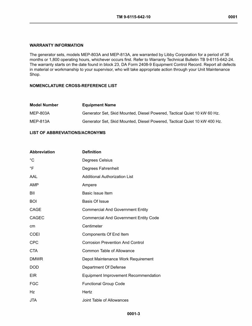
WARRANTY INFORMATION
The generator sets, models MEP-803A and MEP-813A, are warranted by Libby Corporation for a period of 36months or 1,800 operating hours, whichever occurs first. Refer to Warranty Technical Bulletin TB 9-6115-642-24.The warranty starts on the date found in block 23, DA Form 2408-9 Equipment Control Record. Report all defectsin material or workmanship to your supervisor, who will take appropriate action through your Unit MaintenanceShop.
NOMENCLATURE CROSS-REFERENCE LIST
Model Number Equipment Name
MEP-803A Generator Set, Skid Mounted, Diesel Powered, Tactical Quiet 10 kW 60 Hz.
MEP-813A Generator Set, Skid Mounted, Diesel Powered, Tactical Quiet 10 kW 400 Hz.
LIST OF ABBREVIATIONS/ACRONYMS
Abbreviation Definition
°C Degrees Celsius
°F Degrees Fahrenheit
AAL Additional Authorization List
AMP Ampere
BII Basic Issue Item
BOI Basis Of Issue
CAGE Commercial And Government Entity
CAGEC Commercial And Government Entity Code
cm Centimeter
COEI Components Of End Item
CPC Corrosion Prevention And Control
CTA Common Table of Allowance
DMWR Depot Maintenance Work Requirement
DOD Department Of Defense
EIR Equipment Improvement Recommendation
FGC Functional Group Code
Hz Hertz
JTA Joint Table of Allowances

TM 9-6115-642-10 0001
LIST OF ABBREVIATIONS/ACRONYMS – CONTINUED
0001-4
kg Kilogram
kPa Kilopascals
kVa Kilovolt-ampere
kW Kilowatt
kW Kilowatt
L Liter
lbf•ft Foot Pound•Force
m Meter (Metric Measure)
mS Millisecond
MTOE Modified Table of Organization and Equipment
NATO North Atlantic Treaty Organization
NBC Nuclear Biological Chemical
NHA Next Higher Assembly
NIIN National Item Identification Number
NSN National Stock Number
N•m Newton•Meter
P/N Part Number
pa Pascal
PMCS Preventive Maintenance Checks And Services
PSI Pounds per Square Inch
SMR Source, Maintenance, And Recoverability
TAMMS The Army Maintenance Management System
UOC Usable On Code
V Volts
VAC Volts Alternating Current
VDC Volts Direct Current
END OF WORK PACKAGE

TM 9-6115-642-10 0002
0002-1
OPERATOR MAINTENANCE
EQUIPMENT DESCRIPTION AND DATA
EQUIPMENT CHARACTERISTICS, CAPABILITIES, AND FEATURES
The generator sets, models MEP-803A and MEP-813A (Figure 1), are fully enclosed, self-contained. skid-mounted, portable units. They are equipped with controls. instruments and accessories necessary for operation.The generator sets consist of a diesel engine, brushless generator. excitation system, speed governing system,fuel system, 24 VDC starting system, control system and fault system.
NOTEAll locations referenced in Figure 1 are given facing the control box side (rear) of the genera-tor set.

TM 9-6115-642-10 0002
0002-2
LOCATION AND DESCRIPTION OF MAJOR COMPONENTS
Legend
1 Oil Filter2 Dipstick3 Fuel Filter/Water Separator4 AC Generator5 Dead Crank Switch6 Engine7 Batteries8 Water Pump
9 Radiator10 Fuel Tank11 Air Cleaner Assembly12 Muffler13 Fan Belt14 Battery Charging Alternator15 Stater16 NATO Slave Receptacle
17 Skid Base18 Load Output Terminal Board19 Control Panel Assembly20 Frequency Adjust Control21 Malfunction Indicator Panel22 Convenience Receptacle
Figure 1. Generator Set Components.
Oil Filter (1)
The oil filter is located in the engine compartment on the left side. The filter removes impurities from the enginelubricating oil.
Dipstick (2)
The dipstick is located in the engine compartment on the left side. The dipstick shows the lubricating oil level inthe engine crankcase.

TM 9-6115-642-10 0002
LOCATION AND DESCRIPTION OF MAJOR COMPONENTS – CONTINUED
0002-3
Fuel Filter/Water Separator (3)
The fuel filter/water separator is located to the rear of the engine compartment on the left side. The elementremoves impurities and water from the diesel fuel.
AC Generator (4)
The AC generator is a single bearing, drip-proof, synchronous, brushless, three phase, fan-cooled generator. Thegenerator is coupled directly to the rear of the diesel engine.
Dead Crank Switch (5)
The Dead Crank Switch is located in the engine compartment on the left side For maintenance purposes theswitch allows the engine to be cranked without starting.
Engine (6)
The generator is powered by a four cylinder, four cycle, fuel injected, naturally-aspirated, liquid-cooled dieselengine which occupies the front half of the generator set. The engine is also equipped with a fuel filter/water sep-arator, oil filter, and an air cleaner assembly. Protection devices automatically stop the engine during conditions ofhigh coolant temperature, low oil pressure, no fuel, over-voltage.
Batteries (7)
Two batteries are required, one on each side of the generator set. The batteries are maintenance free, lead acid,12 volt type, connected in series. After starting, the generator set is capable of operating with batteries removed.A fuse and a diode, located behind the control panel assembly, protects the generator set if the batteries areincorrectly connected.
Water Pump (8)
The water pump is located in the engine compartment on the front of the engine. The pump circulates the enginecoolant through the engine block and the radiator.
Radiator (9)
The radiator is located at the front of the generator set. It acts as a heat exchanger for the engine coolant.
Fuel Tank (10)
The 9 gallon (34 L) fuel tank is located in the front of the generator set below the engine and between the skidbase side members. The fuel tank is a fuel reservoir and has sufficient capacity to enable the generator set tooperate for at least 8 hours without refueling.
Air Cleaner Assembly (11)
The air cleaner assembly is located on the right side behind the engine. It consists of a dry-type, disposable air fil-ter element made of paper and canister. The air cleaner assembly features a dust collector which traps large dustparticles. The air cleaner assembly has a restriction indicator which will indicate red when the air filter elementrequires servicing.

TM 9-6115-642-10 0002
LOCATION AND DESCRIPTION OF MAJOR COMPONENTS – CONTINUED
0002-4
Muffler (12)
The muffler and exhaust tubing are connected to the exhaust manifold on the engine. The exhaust exits from thetop of the generator set housing. Gases are exhausted upward.
Fan Belt (13)
The fan belt is located in the engine compartment on the front of the engine. The belt drives the fan, water pumpand battery charging alternator.
Battery Charging Alternator (14)
The battery charging alternator is located on the right side of the engine. It is capable of maintaining the batteriesin a state of full charge in addition to providing the required 24 VDC control power.
Starter (15)
The starter is located on the right side of the engine. The electric starter mechanically engages the engine fly-wheel in order to start the diesel engine.
NATO Slave Receptacle (16)
The NATO slave receptacle is located on the right side (rear) of the generator set. It is used for slave starting.
Skid Base (17)
The skid base supports the generator set. It has fork lift access openings and cross members for short distancemovement. The skid base has provisions in the bottom for installation of the generator set on a trailer.
Load Output Terminal Board (18)
The load output terminal board is located on the right side (rear) of the generator set. Four output terminals arelocated on the board. They are marked L1, L2, L3 and LO. A fifth terminal, marked GND, is located next to theoutput terminals and serves as equipment ground for the generator set. A removable, solid copper bar is con-nected between the LO and GND terminals.
Control Panel Assembly (19)
The generator set control panel assembly is located at the rear of the generator set and contains controls andinstruments for operating the engine and the generator.
Frequency Adjust Control (20)
The Frequency Adjust Control is located at the rear left side of generator set. It is used to adjust the generator fre-quency output.
Malfunction Indicator Panel (21)
The malfunction indicator panel is located to the left of the control panel assembly. It indicates malfunctions of thegenerator set components.

TM 9-6115-642-10 0002
LOCATION AND DESCRIPTION OF MAJOR COMPONENTS – CONTINUED
0002-5
Convenience Receptacle (22)
The convenience receptacle is a 10 Amp, 120 VAC receptacle used to operate small plug in type equipment. It isprotected by a Ground Fault Circuit Interrupter located below the malfunction indicator panel (21), an overload cir-cuit breaker located inside the control box, and an in-line fuse on generator sets, contract number DAAK01-88- D-D080. The convenience receptacle power is available at all times during operation of the generator set.
DIFFERENCES BETWEEN MODELS
The differences between models of the generator sets covered in this manual are as follows:
Model MEP-803A is equipped with a 60 Hz generator.
Model MEP-813A is equipped with a 400 Hz generator.
EQUIPMENT DATA
For a list of Leading Particulars refer to Table 1
Table 1. Leading Particulars.
1. Generator Set:
Model Numbers:
10 kW 60 Hz Tactical Quiet MEP-803A
10 kW 400 Hz Tactical Quiet MEP-813A
National Stock Numbers:
10 kW 60 Hz Tactical Quiet NSN 6115-01-275-5061
10 kW 400 Hz Tactical Quiet NSN 6115-01-274-7392
Overall Length:
MEP-803A 62 in. (157.5 cm)
MEP-813A 62 in. (157.5 cm)
Overall Width:
MEP-803A 32 in. (81.28 cm)
MEP-813A 32 in. (81.28 cm)
Overall Height:
MEP-803A 37 in. (93.98 cm)
MEP-813A 37 in. (93.98 cm)
Dry Weights (less Basic Issue Items):
MEP-803A 1,140 lb. (516.4 kg)
MEP-813A 1,170 lb. (530 kg)
Wet Weights:
MEP-803A 1,242 lb. (562.6 kg)
MEP-813A 1,272 lb. (576.2 kg)

TM 9-6115-642-10 0002
EQUIPMENT DATA – CONTINUED
Table 1. Leading Particulars. – Continued
0002-6
2. Engine:
Manufacturer Onan
Model DN4M
Type Naturally-aspirated, four cylinder, four cycle diesel
Displacement 114 cu. in. (1.9 L)
Altitude Degradation, 4,000 to 8,000 ft.(1,220 to 2,240 m) 3.5% per 1,000 feet (305 m)
Firing Order 1, 3, 4, 2
Cold Weather Starting Aid System Use When temperature is +40 °F (4 °C)
Valve Tappet Clearance Adjustment None Required
3. Cooling System:
Type Pressurized radiator and pump
Capacity 8.2 qts. (7.8 L)
Normal Operating Temperature 170-200 °F (77-93 °C)
Temperature Indicating System
Voltage Rating 24 VDC
4. Lubricating System:
Type Full flow, circulating pressure
Oil Pump Type Positive displacement gear
Normal Operating Pressure 25-60 psi (172-414 kPa)
Oil Filter Type Full flow, spin-on, replaceable element
Lubricating System Capacity 5.9 qts. (5 6 L)
Pressure Indicating System
Voltage Rating 24 VDC
5. Fuel System:
Type of Fuel DF-1, DF-2, DF-A, JP4, JP5, JP8
Fuel Tank Capacity 9 gal. (34 L)
Fuel Consumption Rate 60 Hz: .99 gal. (3.75 L) per hour
400 Hz: 1.07 gal. (4.05 L) per hour
Auxiliary Fuel Pump:
Voltage Rating 24 VDC
Delivery Pressure 5.0-6.5 psi (34.5-65.5 kPa) range
Fuel Level Switch:
Type Float
Current 3.0 amp at 6 to 32 VDC
6. Engine Starting System:
Batteries Two 12 VDC, connected in series

TM 9-6115-642-10 0002
EQUIPMENT DATA – CONTINUED
Table 1. Leading Particulars. – Continued
0002-7
Starter:
Manufacturer Onan
Model 191-1550
Voltage Rating 24 VDC
Drive Type Gear Reduction
Battery Charging Alternator:
Manufacturer Prestolite
Models 8EM3005CA and 8MR3005CA
Rating 18 amps at 24 VDC
Protective Fuse 30 amps
7. AC Generator:
Manufacturer Onan
MEP-803A MEP-813A
Type Rotating field synchro-nous
Rotating field synchro-nous
Load Capacity 10 kW 10 kW
Current Rating: 60 Hz: 400 Hz:
120/240 volt connection 52 amps 52 amps
120/208 volt connection 34 amps 34 amps
120 volt connection 104 amps 104 amps
Power Factor 0.8 0.8
Cooling Fan cooled Fan cooled
Drive Type Direct coupling Direct coupling
Duty Classification continuos continuos
8. Protective Devices:
Low Oil Pressure Switch:
Trip Temperature 15 ±3 psi (103.4 ±20.7 kPa)
Voltage Rating 24 VDC
Current Rating 5 amps
Coolant High Pressure Switch:
Trip Temperature 225 °F ±5 °F (107 °C ±3 °C)
Voltage Rating 12-24 VDC
Current Rating 5 amps
Overvoltage:
Trip Point Conditions 153 ±3 VAC for no less than 200 mS (120 VAC coilwinding)
Trip Point No more than 1.25 seconds after trip conditionsexist.

TM 9-6115-642-10 0002
EQUIPMENT DATA – CONTINUED
0002-8
END OF WORK PACKAGE

TM 9-6115-642-10 0003
0003-1
OPERATOR MAINTENANCE
THEORY OF OPERATION
INTRODUCTION
This WP contains functional descriptions of the generator set and explains how the controls and indicators interactwith the system.
ENGINE STARTING SYSTEM
Figure 1. Engine Starting System.
The Engine Starting System (Figure 1), consists of two 12-Volt batteries connected in series, a starter, a 24 Voltbattery charging alternator, a magnetic pickup (for sensing engine speed) and the related switches and relaysrequired for control of the starting system. For engine cranking, battery power is supplied to the starter motor

TM 9-6115-642-10 0003
ENGINE STARTING SYSTEM – CONTINUED
0003-2
through the starter solenoid which in turn is controlled by the cranking relay. The starter then engages the engineflywheel causing the engine to turn over. For engine starting, the DEAD CRANK switch must be in the NORMALposition, the DC Control power circuit breaker must be pushed in, the EMERGENCY STOP SWITCH must be inthe OUT position, and the MASTER SWITCH is moved to the START position. The cranking relay is then con-trolled by a circuit consisting of the crank disconnect relay and crank disconnect switch. As the engine acceleratesto the preset speed (sensed by the magnetic pickup), the crank disconnect switch opens and de-energizes thecranking relay to stop and disengage the starter. The starting sequence may also be stopped by moving the MAS-TER SWITCH to OFF. The engine may be cranked without starting by use of the DEAD CRANK switch. With theDEAD CRANK switch in the CRANK position, the cranking day, starter solenoid and starter motor are energizedwithout activating any other starting or control function.
The batteries are charged by the battery charging alternator that is belt driven by the engine. Generator set con-trol system power is also supplied by the battery charging alternator. The BATTERY CHARGE ammeter indicatesthe charge/discharge rate of the batteries, from -10 AMPS to +20 AMPS, in 5 AMPS increments. Normal oper-ating indication depends on the state of charge in the batteries. A low charge, such as exists immediately afterengine starting. will cause a high reading (needle moves toward CHARGE area). When the charge in the batterieshas been restored, the indicator moves near zero, 0.
FUEL SYSTEM
Figure 2. Fuel System.

TM 9-6115-642-10 0003
FUEL SYSTEM – CONTINUED
0003-3
The Fuel System (Figure 2), consists of piping, fuel tank. fuel filter, electrically driven transfer pump, fuel fil-ter/water separator, four injection pumps and four injectors, one for each cylinder. Fuel is drawn from the fuel tankby the transfer pump when the MASTER SWITCH is in the PRIME & RUN position. After reaching the transferpump, fuel passes through a fuel filter/water separator where water and small impurities are removed. The fuelthen goes to the injection pumps where it is pressurized and pushed into the injectors. Through the injectors fuelenters the diesel engine combustion chamber, where it is mixed with air and ignited. The fuel that is not used isreturned to the fuel tank via an excess fuel return line.
The Auxiliary Fuel System consists of an external fuel supply, piping, fuel filter, a 24 VDC auxiliary fuel pump anda fuel level float switch. When the MASTER SWITCH is set on PRIME & RUN AUX FUEL it actuates the auxil-iary fuel pump and transfers fuel from the external fuel supply to the generator fuel tank. The fuel level float switchshuts off the auxiliary fuel pump when the generator fuel tank is full and reactivates the pump as the level drops.The FUEL LEVEL indicator indicates fuel level of generator fuel tank from (E) empty to (F) full in quarter tankincrements.

TM 9-6115-642-10 0003
0003-4
ENGINE COOLING SYSTEM
Figure 3. Engine Cooling System.
The Engine Cooling System (Figure 3) consists of a radiator, hoses, thermostat, water pump, a belt driven fan,and cooling jackets. The water pump forces coolant through passages (cooling jackets) in the engine block andcylinder head where the coolant absorbs heat from the engine. When the engine reaches normal operating tem-perature, the thermostat opens and the heated coolant flows through the upper radiator hose assembly into theradiator. The cooling fan circulates air through the radiator where the coolant temperature is reduced.
A coolant high temperature switch provides automatic shut down in the event that coolant temperature exceeds225 ±5 °F (107 ±3 °C) . The COOLANT TEMP indicator indicates the engine coolant temperature, from 120 °F to240 °F (48 °C to 115 ° C).

TM 9-6115-642-10 0003
0003-5
LUBRICATION SYSTEM
Figure 4. Engine Lubrication System.
The Lubrication System (Figure 4) consists of an oil sump, dipstick, pump, oil pressure sender, and filter. The oilsump is a reservoir for engine lubricating oil. The dipstick indicates oil level in the sump. A pump draws oil fromthe sump and through a screen removing large impurities. The oil then passes through a spin-on type filter whered impurities are removed. From the filter, oil enters the engine and is distributed to the engine's internal movingparts.
After passing through the engine, the oil returns to the oil sump. The OIL PRESSURE indicator indicates oil pres-sure sensed by the oil pressure sender in the engine. The engine will shut off automatically if the oil pressuredrops to a dangerously low level. The oil level can be checked when the engine is not operating.

TM 9-6115-642-10 0003
0003-6
AIR INTAKE AND EXHAUST SYSTEM
Figure 5. Air Intake and Exhaust System.
The Air Intake and Exhaust System (Figure 5). consists of an air cleaner assembly, intake manifold, exhaust man-ifold and muffler. Ambient air is drawn into the air cleaner assembly where it passes through the air cleaner ele-ment.
Airborne dirt is removed and trapped in the element. A restriction indicator, located on the air cleaner assemblyhousing, displays red when the air cleaner element should be serviced. Filtered air is drawn out of the air cleanerassembly through air intake tubes to the air intake manifold where it passes into the engine and is mixed with fuelfrom the injectors.
The engine exhaust gases are expelled into the exhaust manifold. The exhaust manifold channels the gases intothe muffler that deadens the sound of the exhaust gases. The gases pass from the muffler through the muffleroutlet and are vented upward from the generator set housing.

TM 9-6115-642-10 0003
AIR INTAKE AND EXHAUST SYSTEM – CONTINUED
0003-7
Cold outside temperatures make starting the engine difficult. To improve engine starting, a cold weather startingaid has been provided that features four preheaters.The preheaters warm up the air intake manifold when theMASTER SWITCH is in the PREHEAT position
OUTPUT SUPPLY SYSTEM
Figure 6. Output Supply System.
The Output Supply System (Figure 6) consists primarily of the generator, the output load terminal board, the ACvoltage reconnection switch, AM-VM transfer switch and the AC circuit interrupter relay.
Power created by the generator is supplied through the voltage reconnection switch and the AC output load termi-nals on the output load terminal board.
The voltage reconnection switch allows configuration of the generator set for the following voltage ranges:
TM 9-6115-642-10 0003
OUTPUT SUPPLY SYSTEM – CONTINUED
0003-8
120-Volt, single phase, 2 wire.
120/240-Volt, single phase, 3 wire,
120/208-Volt, 3-phase, 4 wire.
The AC INTERRUPTER switch closes and opens the AC circuit interrupt relay. This enables or interrupts thepower flow between the voltage reconnection switch and the output load terminals. The AC circuit interrupterrelay is also opened automatically during any of the specified set faults. The voltage regulator senses AC gener-ator output voltage and provides control voltage to the AC generator exciter to maintain the desired AC genera-tor output voltage. The position of the AM-VM transfer switch selects the output load terminals from which currentand voltage are measured and are indicated on the ammeter (PERCENT RATED CURRENT) and AC volt meter(VOLTS AC).
END OF WORK PACKAGE

TM 9-6115-642-10
CHAPTER 2
OPERATOR INSTRUCTIONS
MEP-813A 10 kW, 400 Hz
GENERATOR SET, SKID MOUNTED, TACTICAL QUIET MEP-803A
10 kW, 60 Hz GENERATOR SET, SKID MOUNTED, TACTICAL QUIET
FOR

TM 9-6115-642-10
CHAPTER 2
OPERATOR INSTRUCTIONS
WORK PACKAGE INDEX
Title WP Sequence No.DESCRIPTION AND USE OF OPERATOR CONTROLS AND INDICATORS ................................................. 0004OPERATION UNDER USUAL CONDITIONS ................................................................................................... 0005OPERATION UNDER UNUSUAL CONDITIONS ............................................................................................. 0006EMERGENCY INFORMATION ......................................................................................................................... 0007

TM 9-6115-642-10 0004
0004-1
OPERATOR MAINTENANCE
DESCRIPTION AND USE OF OPERATOR CONTROLS AND INDICATORS
SCOPE
This WP describes and illustrates the controls and indicators to ensure proper operation of the generator set.
CONTROL PANEL ASSEMBLY
The control panel assembly contains most of the operating controls and indicator for the generator set. Figure 1shows the control panel assembly layout and Table 1 describes each control and indicator.
Table 1. Operator's Controls and Indicators.
Figure 1. Operator's Controls and Indicators.

TM 9-6115-642-10 0004
CONTROL PANEL ASSEMBLY – CONTINUED
Table 1. Operator's Controls and Indicators – Continued
0004-2
KEY CONTROL/INDICATOR FUNCTION 1 FUEL LEVEL indicator Indicates fuel level.
2 Panel lights Illuminates control panel.
3 COOLANT TEMP indicator Indicates engine coolant temperature.
4 OIL PRESSURE indicator Indicates oil pressure.
5 EMERGENCY STOP pushbutton Shuts down generator set.
6 FREQUENCY meter (Hz) Indicates generator set output frequency.
7 Ammeter (PERCENT RATED CUR-RENT METER)
Indicates generator set load current as a percent of rated current.
8 AM-VM transfer switch Allows selection of current and voltage readings between outputload terminals as follows:
SWITCH POSITION VOLTAGE CURRENT
L1 - L2 (3 Phase) L1 - L2 L1
L2 - L3 (3 Phase) L2 - L3 L2
L3 - L1 (3 Phase) L3 - L1 L3
L3 - L0 (3 Phase) L3 - L0 L3
L3 - L1 (1 Phase) L3 - L0 L3
L3 - L0 (1 Phase) L3 - L0 L3
9 AC Voltmeter (VOLTS AC) Indicates output voltage of generator set.
10 VOLTAGE adjust Potentiometer Adjusts generator set voltage.
11 BATTLE SHORT light Amber light indicates battle short switch on.
12 BATTLE SHORT switch Bypasses protective devices.
13 PANEL LIGHTS switch ON - Activates or deactivates panel lights.
14 AC CIRCUIT INTERRUPTERswitch
Opens and closes AC circuit interrupter relay.
15 AC CIRCUIT INTERRUPTER light Green light indicates AC circuit interrupter relay is closed.
16 MASTER SWITCH PREHEAT - Energizes heater plugs.
OFF - Deenergizes all circuits, except panel lights.
PRIME 8 RUN AUX FUEL -Energizes generator set run circuitswith fuel pump operating and with auxiliary fuel pump system acti-vated.
PRIME 8 RUN - Energizes generator set run circuits with fuelpump operating and auxiliary fuel system deenergized.
START - Energizes starter.
17 Time meter (TOTAL HOURS) Indicates total engine operating hours.

TM 9-6115-642-10 0004
CONTROL PANEL ASSEMBLY – CONTINUED
Table 1. Operator's Controls and Indicators – Continued
0004-3
KEY CONTROL/INDICATOR FUNCTION18 BATTERY CHARGE ammeter Indicates charge/discharge rate of batteries.
19 DC CONTROL POWER circuitbreaker (CB1) (Located BehindControl Panel)
Energizes or deenergizes DC circuits.
20 AC Voltage Reconnection Switch(Located Behind Control Panel)
Selects 120/208 VAC, three-phase; 120 VAC, single phase; or120/240 VAC, single phase output at load terminal board.
21 BATTERY CHARGER FUSE (FU1)(Located Behind Control Panel)
Protects battery charging alternator.
MALFUNCTION INDICATOR PANEL
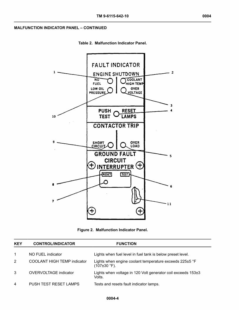
The malfunction indicator panel (Figure 2) is located to the left of the control panel. It contains a series of lightswhich indicate a generator set failure or abnormal operating condition. Table 2 describes each indicator light.
TM 9-6115-642-10 0004
MALFUNCTION INDICATOR PANEL – CONTINUED
0004-4
Table 2. Malfunction Indicator Panel.
Figure 2. Malfunction Indicator Panel.
KEY CONTROL/INDICATOR FUNCTION 1 NO FUEL indicator Lights when fuel level in fuel tank is below preset level.
2 COOLANT HIGH TEMP indicator Lights when engine coolant temperature exceeds 225±5 °F(107±30 °F).
3 OVERVOLTAGE indicator Lights when voltage in 120 Volt generator coil exceeds 153±3Volts.
4 PUSH TEST RESET LAMPS Tests and resets fault indicator lamps.

TM 9-6115-642-10 0004
MALFUNCTION INDICATOR PANEL – CONTINUED
Table 2. Malfunction Indicator Panel – Continued
0004-5
KEY CONTROL/INDICATOR FUNCTION5 OVER LOAD indicator Lights when current in any phase exceeds 110 percent of rated
current.
6 GROUND FAULT CIRCUIT INTER-RUPTER TEST pushbutton
Tests Ground Fault Circuit Interrupter.
7 Ground Fault Circuit Interrupter indi-cator
Mechanically trips red indicator, at ground fault condition in circuitof convenience receptacle.
8 Ground Fault Circuit InterrupterPUSH TO TEST Pushbutton
Depress to reset Ground Fault Circuit Interrupter after test orground fault has occurred.
9 SHORT CIRCUIT indicator Lights when generator set output in any phase exceeds 425±25percent of rated current.
10 LOW OIL PRESSURE indicator Lights when engine lubrication systems pressure is less than 15 +3 psi (103.4±20.7 kPa) during engine operation.
11 Convenience Receptacle OverloadCircuit Breaker (10-amp in-line fuseon generator sets, contract numberDAAK01-88-D-D080)
Circuit breaker trips on when load on convenience receptacleexceeds 10 amps (fuse blows on generator sets, contract numberDAAK01-88-D-D080).
FREQUENCY ADJUST CONTROL
The frequency adjust control (Figure 3), is to the left and below the control panel. Table 3 describes each part andits function.
Table 3. Frequency Adjust Control.
Figure 3. Frequency Adjust Control.
KEY CONTROL/INDICATOR FUNCTION 1 Locking Ring Turn locking ring counterclockwise to unlock frequency adjust con-
trol. Turn locking ring clockwise to lock frequency adjust control atdesired setting.

TM 9-6115-642-10 0004
FREQUENCY ADJUST CONTROL – CONTINUED
Table 3. Frequency Adjust Control – Continued
0004-6
KEY CONTROL/INDICATOR FUNCTION2 Frequency adjust button Press frequency adjust button and pull frequency adjust knob to
increase frequency. Press frequency adjust button and push fre-quency adjust knob to decrease frequency. This enables a rapidadjustment of frequency.
3 Frequency adjust knob Turn knob clockwise to increase frequency and counterclockwiseto decrease frequency. This provides a fine adjustment in fre-quency.
END OF WORK PACKAGE

TM 9-6115-642-10 0005
0005-1
OPERATOR MAINTENANCE
OPERATION UNDER USUAL CONDITIONS
INITIAL SETUP:
Tools and Special Tools
Generator Mechanical Tool Kit P/N (S25885) (NSN 4910-01-490-6453)
Materials/Parts
Ground Rod Assembly P/N Ground Conductor Cable P/N
Personnel Required
One (1): Power Generation Mechanic (91D)
References
WP 0004 (Table 1 & Figure 1, Item 10 & Figure 1,Item 10)WP 0011 (Table 1)
Equipment Condition
Grounded, Off & Operational (Stopping Procedure,WP 0005)
SCOPE
This WP provides information and guidance for generator set operation under normal conditions, refer to FM20-31.

TM 9-6115-642-10 0005
0005-2
ASSEMBLY AND PREPARATION FOR USE
Installation of Ground Rod
WARNINGDo not operate the generator set until it has been connected to a suitable ground. Seriousinjury or death can result from operating an ungrounded generator set.
Figure 1. Grounding Connections.
1. Insert ground cable (Figure 1, Item 2) through slot on load output terminal board terminal marked GND (1).Tighten terminal nut.
2. Connect coupling (5) to ground rod (4) and screw driving stud (3) into coupling (5). Make sure that drivingstud (3) seats on ground rod (4).

TM 9-6115-642-10 0005
ASSEMBLY AND PREPARATION FOR USE – CONTINUED
0005-3
3. Drive ground rod into ground until coupling is just above surface.
4. Remove driving stud and install another section of ground rod.
5. Install another coupling (5) and driving stud (3). Drive ground rod down until new coupling is just aboveground surface.
6. Repeat Steps 4 and 5 until ground rod has been driven eight feet or deeper, providing an effective ground.
7. Connect clamp (6) and ground cable (2) to ground rod (4) and tighten clamp screw.
Installation of Load Cables
WARNINGNever attempt to connect or disconnect load cables while the generator set is running. Failureto observe this warning could result in severe personal injury or death by electrocution.
CAUTIONDo not connect the load cables to the convenience receptacle. Failure to observe this cautioncan result in damage to the generator set.
1. Shutdown generator set.
CAUTIONWhen using single phase connections, always attempt to balance loads between ter-minals (do not connect all loads between one terminal and LO). Failure to observe thiscaution can result in damage to generator set.
2. Select required output terminals from Table 1.
3. Open output load terminal door.
WARNINGJumper will not be removed unless the equipment being powered specifically requiredan isolated ground (floating ground). Failure to comply with this warning can causeinjury or death to personnel.
4. Ensure jumper is securely fastened between LO and ground.
5. Using terminal nut wrench (Figure 2, Item 3) loosen terminal nuts (1) on terminals (2) selected in Step 2.
6. Insert ends of load cables through load cable exit. then insert ends of cables into slots of load terminal studs(2).
7. Tighten load terminal nuts (1).
8. Secure wrench (3) in bracket inside load terminal door, and close door.
Table 1. Load Terminal, AC Voltage ReconnectionSwitch and AM-VM Transfer Switch Selection.
RECONNEC-TION SWITCHPOSITION
TERMINALS AM-VM TRANS-FER SWITCHPOSITION
VOLTAGEREADING
CURRENTREADING (TER-MINAL)
120/208V 3PH L1, L2, L1-L2 3 PHASE 208 VOLTS L1

TM 9-6115-642-10 0005
ASSEMBLY AND PREPARATION FOR USE – CONTINUED
Table 1. Load Terminal, AC Voltage Reconnection Switchand AM-VM Transfer Switch Selection. – Continued
0005-4
RECONNEC-TION SWITCHPOSITION
TERMINALS AM-VM TRANS-FER SWITCHPOSITION
VOLTAGEREADING
CURRENTREADING (TER-MINAL)
L3, LO L2-L3 3 PHASE 208 VOLTS L2
L3-L1 3 PHASE 208 VOLTS L3
L3-LO 3 PHASE 120 VOLTS L3
120V 1PH L3-LO L3-LO 1 PHASE 120 VOLTS L3
120/240V 1PH L3-L1 L3-L1 1 PHASE 240 VOLTS L3
L3-LO L3-LO 1 PHASE 120 VOLTS L3
OR
L1-LO L1-LO 1 PHASE 120 VOLTS L1
Figure 2. Installation of Load Cables.
INITIAL ADJUSTMENTS, BEFORE USE, AND SELF-TEST
Perform all before (B) PMCS, refer to WP 0011.

TM 9-6115-642-10 0005
INITIAL ADJUSTMENTS, BEFORE USE, AND SELF-TEST – CONTINUED
0005-5
Initial Adjustments
1. Place DEAD CRANK SWITCH in NORMAL position.
2. Push DC CONTROL POWER circuit breaker in.
3. Ensure AC voltage reconnection switch is positioned to match voltage requirements.
4. Place AM-VM transfer switch in a position corresponding to output terminal load connections, refer to WP0004, Table 1.
5. Pull our EMERGENCY STOP switch.
Self Test
1. Place MASTER SWITCH to PRIME 8 RUN position.
2. Push PRESS TO TEST pushbutton on malfunction indicator panel. Ensure all indicator lights are lit. WhenPRESS TO TEST pushbutton is released, all lights should go out.
3. Press BATTLE SHORT press to test light on the control panel assembly. Ensure indication light is lit. Whenpress to test light is released, light should go out.
4. Press AC CIRCUIT INTERRUPTER press to test light on the control panel assembly. Ensure indicator lightis lit. When press to test light is released, light should go out.
OPERATING PROCEDURES
WARNINGHigh voltage is produced when generator set is in operation. Improper operation could resultin personal injury or a death by electrocution.
WARNINGExhaust discharge contains deadly gases. Do not operate the generator set in enclosedareas unless exhaust discharge is properly vented outside. Severe personal injury or deathdue to carbon monoxide poisoning could result.
Starting Procedures
WARNINGNever attempt to start the generator set if it is not properly grounded. Failure to observe thiswarning could result in serious injury or death by electrocution.
CAUTIONDo not crank engine in excess of 15 seconds. Allow starter to cool at least 15 secondsbetween attempted starts. Failure to observe this caution could result in damage to thestarter.
NOTEAt temperatures below 40 °F (4 °C) it may be necessary to use the Cold Weather StartingAid.

TM 9-6115-642-10 0005
OPERATING PROCEDURES – CONTINUED
0005-6
NOTEEnsure all generator set access doors, except control are closed.
1. In cold weather conditions, place MASTER SWITCH to PREHEAT position for approximately 30 seconds.
2. Rotate MASTER SWITCH to START position.
3. Hold MASTER SWITCH in START position until oil pressure reaches at least 25 psi (172 kPa), voltage hasincreased to its approximate rated value, and engine has reached stable operating speed.
4. Release MASTER SWITCH to PRIME 8 RUN position.
5. If operating with an auxiliary fuel source, rotate MASTER SWITCH to PRIME 8 RUN AUX FUEL position.
NOTEUnder normal conditions warm up engine without load for five minutes. (If required, loadcan be applied immediately.)
6. Check COOLANT TEMP 170-200 °F (77-93 °C) and OIL PRESSURE 25-60 psi (172-414 kPa) indicators fornormal readings.
7. Using VOLTAGE adjust potentiometer (WP 0004, Figure 1, Item 10) and Frequency Adjust Control (WP0004, Figure 3), adjust voltage and frequency to rated values.
8. Press GROUND FAULT CIRCUIT INTERRUPTER TEST pushbutton. Ensure indicator window is clear.Press RESET pushbutton and ensure indicator is red.
9. Place AC CIRCUIT INTERRUPTER switch to CLOSED position.
10. Ensure frequency and voltage are still at required values. Adjust if necessary.
11. Rotate AM-VM transfer switch to each phase position while observing ammeter (PERCENT RATED CUR-RENT meter). If more than rated load is indicated in any phase, reduce load.
WARNINGHigh Voltage is produced when this generator set is in operation. Improper operationcould result in personal injury or death by electrocution.
WARNINGWith any access door open, the noise level of this generator set when operating couldcause hearing damage. Hearing protection must be worn when working near the gener-ator set while running.
12. Perform all DURING (D) OPERATION PMCS requirements in accordance with WP 0011, Table 1.
Stopping Procedure
1. Place AC CIRCUIT INTERRUPTER switch in OPEN position.
2. Allow generator set to operate 5 minutes with no load applied.
3. Place MASTER SWITCH in OFF position.
4. Perform all AFTER OPERATION (A) PMCS requirements in accordance with WP 0011, Table 1.
5. Place DEAD CRANK switch to OFF position

TM 9-6115-642-10 0005
0005-7
USE OF THE CONVENIENCE RECEPTACLE
WARNINGPower is available when the main contactor is open. Avoid accidental contact. Failure toobserve this warning can result in severe personal injury or death by electrocution.
CAUTION
The maximum power rating for the convenience receptacle is 10 Amps. Continuous operationabove 10 Amps can result in damage to the generator set
1. Start the generator set if it is not operating. Refer to Operating Procedures.
2. Ensure the load does not exceed the maximum rating.
3. Reset the Ground Fault Circuit Interrupter.
4. Plug appropriate connector into convenience receptacle.
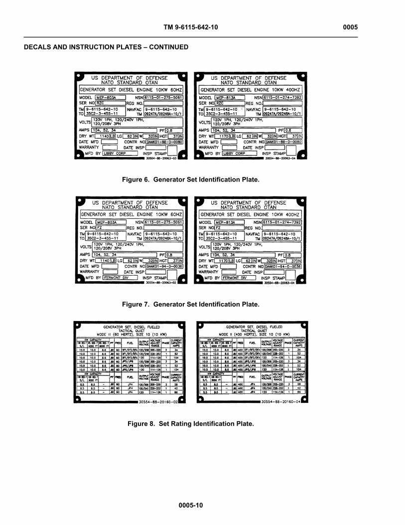
DECALS AND INSTRUCTION PLATES
There are identification and instruction plates on the generator set. Figure 3 through 19 show the location andcontents of each plate on the generator set.

TM 9-6115-642-10 0005
DECALS AND INSTRUCTION PLATES – CONTINUED
0005-8
Figure 3. Operating Instructions (Front and Right Side).

TM 9-6115-642-10 0005
DECALS AND INSTRUCTION PLATES – CONTINUED
0005-9
Figure 4. Operating Instructions Plates (Rear and Left Side).
Figure 5. Operating Instructions Plate.
TM 9-6115-642-10 0005
DECALS AND INSTRUCTION PLATES – CONTINUED
0005-10
Figure 6. Generator Set Identification Plate.
Figure 7. Generator Set Identification Plate.
Figure 8. Set Rating Identification Plate.

TM 9-6115-642-10 0005
DECALS AND INSTRUCTION PLATES – CONTINUED
0005-11
Figure 9. Voltage Connection Caution Plate.
Figure 10. Grounding Stud Plate.
Figure 11. NATO Slave Receptacle Plate.
Figure 12. Diagnostics Plate.

TM 9-6115-642-10 0005
DECALS AND INSTRUCTION PLATES – CONTINUED
0005-12
Figure 13. Convenience Receptacle Plate.
Figure 14. External Fuel Supply Plate.
Figure 15. Battery Connection Instruction Plate.

TM 9-6115-642-10 0005
DECALS AND INSTRUCTION PLATES – CONTINUED
0005-13
Figure 16. Generator Identification Plate.
Figure 17. Frequency Adjust Plate.
Figure 18. Lifting and Tiedown Diagram Plate.
TM 9-6115-642-10 0005
DECALS AND INSTRUCTION PLATES – CONTINUED
0005-14
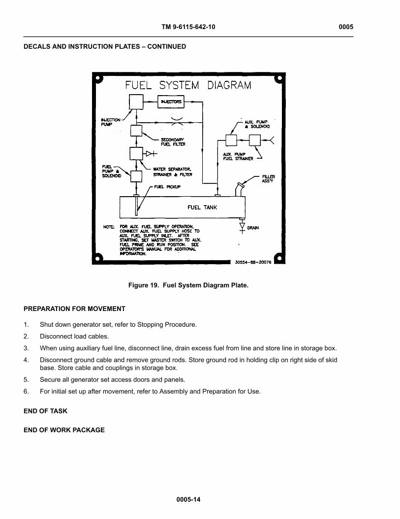
Figure 19. Fuel System Diagram Plate.
PREPARATION FOR MOVEMENT
1. Shut down generator set, refer to Stopping Procedure.
2. Disconnect load cables.
3. When using auxiliary fuel line, disconnect line, drain excess fuel from line and store line in storage box.
4. Disconnect ground cable and remove ground rods. Store ground rod in holding clip on right side of skidbase. Store cable and couplings in storage box.
5. Secure all generator set access doors and panels.
6. For initial set up after movement, refer to Assembly and Preparation for Use.
END OF TASK
END OF WORK PACKAGE

TM 9-6115-642-10 0006
0006-1
OPERATOR MAINTENANCE
OPERATION UNDER UNUSUAL CONDITIONS
INITIAL SETUP:
Tools and Special Tools
Generator Mechanical Tool Kit P/N (S25885) (NSN 4910-01-490-6453)
Materials/Parts
Antifreeze Coolant P/N (81349) A-A-52624 Personnel Required
One (1): Power Generation Mechanic (91D)
References
WP 0014 (Air Cleaner Assembly)WP 0019, NBC Decontamination
Equipment Condition
Grounded, Off & Operational
UNUSUAL ENVIRONMENT/WEATHER
Operation in Extreme Cold Weather Below -25 °F (-31 °C)
The generator set operates in ambient temperatures as low as -25 °F (-31 °C) without special winterization equip-ment. To ensure satisfactory operation under extreme cold weather the following steps must be taken.
WARNINGAvoid contacting metal items with bare skin in extreme cold weather. Failure to observe thiswarning can cause personal injury.
1. Keep generator set and surrounding area as free of ice and snow as practical.
2. Keep fuel tank full to protect against moisture, condensation and accumulation of water.
3. Ensure that proper grade diesel fuel is used.
4. Keep batteries free from corrosion and in a well charged condition.
OPERATION IN EXTREME HEAT ABOVE 120 °F (49 °C)
1. Check vents and radiator air passages frequently for obstructions.
2. Check coolant temperature indicator frequently for any indication of overheating.
3. Allow sufficient space for fuel expansion when filling fuel tank.
4. Keep generator clean and free of dirt. Clean obstructions from generator intake and outlet screens.
5. Clean external surface of engine when generator set is not operating.
OPERATION IN DUSTY OR SANDY AREAS
1. If possible, provide a shelter for generator set. Use available natural barriers to shield generator set fromblowing dust or sand.

TM 9-6115-642-10 0006
OPERATION IN DUSTY OR SANDY AREAS – CONTINUED
0006-2
2. Wet down dusty and sandy surface areas around generator set frequently if water is available.
3. Keep all access doors closed, as much as possible, to prevent entry of dust and sand into housing assem-bly.
4. Wipe dust and sand frequently from the generator set external surface and components. Wash exterior sur-faces frequently with clean water when generator set is not operating.
5. Service engine air cleaner assembly frequently to compensate for intake of additional dust or sand. Refer toWP 0014.
6. Drain sediment frequently from fuel filter/water separator. When servicing fuel tank be careful to prevent dustor sand from entering fuel tank.
7. Change engine oil and oil filter frequently.
8. Store oil and fuel in dust-free containers.
9. Ensure that generator set ground connections are free of dust and sand and connections are tight beforestarting the unit.
OPERATION UNDER RAINY OR HUMID CONDITIONS
CAUTIONFailure to remove waterproof material before operating generator set could result in equip-ment damage.
1. If possible, provide a shelter for generator set. Cover generator set with canvas or other waterproof materialwhen it is not being operated.
2. Provide adequate drainage to prevent water from accumulating on operation site.
3. Keep all generator set access doors closed, as much as possible, to prevent entry of water into housingassembly.
4. Drain water frequently from fuel filter/water separator
WARNINGDC voltages are present at generator set electrical components even with generator setshutdown. Avoid grounding yourself when touching any electrical components. Failureto follow this warning can result in personal injury.
5. Remove moisture from generator set components before and after each operating period.
6. Keep fuel tank full to protect against moisture, condensation and accumulation of water.
OPERATION IN SALT WATER AREAS
CAUTIONFailure to remove waterproof material before operating generator set could result in equip-ment damage.
1. If possible. provide a shelter for the generator set. Locate generator set so that radiator faces into prevailingwinds. Use natural barriers or, if possible, construct a barrier to protect generator set from salt water. Covergenerator set with canvas or other waterproof material when it is not being operated.

TM 9-6115-642-10 0006
OPERATION IN SALT WATER AREAS – CONTINUED
0006-3
2. Keep all generator access doors closed, as much as possible, to prevent entry of salt water into housingassembly.
3. Wash exterior surfaces frequently with clean water when generator set is not operating.
4. Check wiring connections for corrosion insulation for signs of deterioration.
OPERATION IN SALT WATER AREAS
The generator set will operate at elevations up to 4,000 feet (1,219.1 meters) above sea level without specialadjustment or reduction in load. At elevations greater than 4,000 feet (1219.1 meters) above sea level, the kilo-watt rating is reduced approximately 3.5 percent for each additional 1,000 feet (304.8 meters).
OPERATION WHILE IN CONTAMINATED AREAS
The generator set is capable of being operated by personnel wearing nuclear, biological, or chemical (NBC) pro-tective clothing without special tools or supporting equipment. Refer to FM 3-5, NBC Decontamination for informa-tion on decontamination procedures. Specific procedures for the generator set are the following:
1. Control panel indicators sealing gasket, rubber sleeves, and rope draw cords at output terminal accessports, control panel door gaskets, access door gaskets, rubber tubing, and belts within the engine compart-ment, coverings for electrical conduits, external water drain tubing, and retaining cords for slave receptaclecovers will absorb and retain chemical agents. Replacement of these items is the recommended method ofdecontamination.
2. Lubricants, fuel, coolant, or battery fluids may be present on the external surfaces of the generator set orcomponents due to leaks or normal operation. These fluids will absorb NBC agents. The preferred methodof decontamination is removal of these fluids using conventional decontamination methods in accordancewith FM 3-5.
3. Continued decontamination of external generator set surfaces with supertropical bleach (STB)/decontamina-tion solution number 2 (DS2) will degrade clear plastic indicator coverings to a point where reading indica-tors will become impossible. This problem will become more evident for soldiers wearing protective masks.Therefore, the use of STB or DS2 decontamination in these areas should be minimized. Indicators shouldbe decontaminated with warm soapy water.
4. External surfaces of the control panel assembly that are marked with painted or stamped lettering will notwithstand repeated decontamination with STB or DS2 without degradation of this lettering. Therefore, therecommended method of decontamination for these areas is with warm soapy water.
5. Areas that will entrap contaminants, making efficient decontamination extremely difficult, include the follow-ing:
a. Exposed heads of screws.
b. Areas adjacent to and behind exposed wiring conduits.
c. Hinged areas or access doors.
d. Retaining chains for external receptacle covers.
e. Areas around the tie-down/lifting rings, crevices around access doors, external screens covering ven-tilation areas, the external oil drain valve, and areas adjacent to the external fuel drain valve.
f. Areas behind knobs and switches on the control panel, externally mounted equipment specificationdata plates, external receptacle covers, access doors, access door locking mechanisms, recessedwells for access door handles, fuel cap, load terminal board, slave receptacles, and frequency adjust-ment controls.

TM 9-6115-642-10 0006
OPERATION WHILE IN CONTAMINATED AREAS – CONTINUED
0006-4
Replacements of these items, if available, is the preferred method of decontamination. Conventionalmethods of decontamination should be used on these areas, while stressing the importance of thor-oughness and the probability of some degree of continuing contact and vapor hazard.
6. In an NBC contaminated environment, the generator set should be operated with all access doors closed toreduce the effects of contamination.
7. The use of overhead shelters or chemical protective covers is recommended as an additional means of pro-tection against contamination in accordance with FM 3-5. However, if using covers, care should be taken toprovide adequate space for air flow and exhaust.
8. For additional NBC information, refer to FM 3-3 and FM 3-4. Other services use applicable publications forNBC.
END OF TASK
END OF WORK PACKAGE
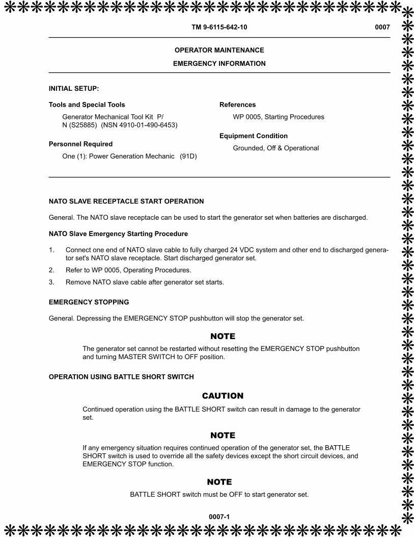
❋❋❋❋❋❋❋❋❋❋❋❋❋❋❋❋❋❋❋❋❋❋❋❋❋❋❋❋❋❋TM 9-6115-642-10 0007
❋❋
❋❋
❋❋
❋❋
❋❋
❋❋
❋❋
❋❋
❋❋
❋❋
❋❋
❋❋
❋❋
❋❋
❋❋
❋❋
❋❋
❋❋
❋❋
❋
0007-1
❋❋❋❋❋❋❋❋❋❋❋❋❋❋❋❋❋❋❋❋❋❋❋❋❋❋❋❋❋❋
OPERATOR MAINTENANCE
EMERGENCY INFORMATION
INITIAL SETUP:
Tools and Special Tools
Generator Mechanical Tool Kit P/N (S25885) (NSN 4910-01-490-6453)
Personnel Required
One (1): Power Generation Mechanic (91D)
References
WP 0005, Starting Procedures Equipment Condition
Grounded, Off & Operational
NATO SLAVE RECEPTACLE START OPERATION
General. The NATO slave receptacle can be used to start the generator set when batteries are discharged.
NATO Slave Emergency Starting Procedure
1. Connect one end of NATO slave cable to fully charged 24 VDC system and other end to discharged genera-tor set's NATO slave receptacle. Start discharged generator set.
2. Refer to WP 0005, Operating Procedures.
3. Remove NATO slave cable after generator set starts.
EMERGENCY STOPPING
General. Depressing the EMERGENCY STOP pushbutton will stop the generator set.
NOTEThe generator set cannot be restarted without resetting the EMERGENCY STOP pushbuttonand turning MASTER SWITCH to OFF position.
OPERATION USING BATTLE SHORT SWITCH
CAUTIONContinued operation using the BATTLE SHORT switch can result in damage to the generatorset.
NOTEIf any emergency situation requires continued operation of the generator set, the BATTLESHORT switch is used to override all the safety devices except the short circuit devices, andEMERGENCY STOP function.
NOTEBATTLE SHORT switch must be OFF to start generator set.

❋❋❋❋❋❋❋❋❋❋❋❋❋❋❋❋❋❋❋❋❋❋❋❋❋❋❋❋❋❋TM 9-6115-642-10 0007
OPERATION USING BATTLE SHORT SWITCH – CONTINUED
❋❋
❋❋
❋❋
❋❋
❋❋
❋❋
❋❋
❋❋
❋❋
❋❋
❋❋
❋❋
❋❋
❋❋
❋❋
❋❋
❋❋
❋❋
❋❋
0007-2
❋❋❋❋❋❋❋❋❋❋❋❋❋❋❋❋❋❋❋❋❋❋❋❋❋❋❋❋❋❋
1. Start generator set if set is not running. Refer to WP 0005, Starting Procedures.
2. Lift cover on BATTLE SHORT switch and position switch to ON.
END OF WORK PACKAGE

TM 9-6115-642-10
CHAPTER 3
OPERATOR TROUBLESHOOTING PROCEDURES
MEP-813A
MEP-803A
10 kW, 400 Hz GENERATOR SET, SKID MOUNTED, TACTICAL QUIET
10 kW, 60 Hz GENERATOR SET, SKID MOUNTED, TACTICAL QUIET
FOR
TM 9-6115-642-10
CHAPTER 3
OPERATOR TROUBLESHOOTING PROCEDURES
WORK PACKAGE INDEX
Title WP Sequence No.TROUBLESHOOTING INDEX .......................................................................................................................... 0008TROUBLESHOOTING PROCEDURES ............................................................................................................ 0009

TM 9-6115-642-10 0008
0008-1
OPERATOR MAINTENANCE
TROUBLESHOOTING INDEX
GENERAL
This section lists common malfunctions you may find during operation of the generator set.You should perform thetests/inspections and corrective actions in the order listed.
This manual cannot list all malfunctions that may occur, nor all tests or inspections and corrective actions. If amalfunction is not listed or is not corrected by listed corrective actions, notify your supervisor.
NOTEAir Force and Marine Corps users may perform maintenance only as authorized.
SYMPTOM TROUBLESHOOTING PROCEDURES INDEX
MALFUNCTION/SYMPTOM TROUBLESHOOTING PROCEDURE
COOLING SYSTEM
COOLANT TEMPERATURE indicator indicates engineoverheating.
Symptom 11
ELECTRICAL SYSTEM
BATTERY CHARGE ammeter shows low or nocharge.
Symptom 12
BATTERY CHARGE ammeter shows excessivecharge.
Symptom 13
AC VOLTMETER (VOLTS AC) Indicates low voltage. Symptom 14
AC VOLTMETER (VOLTS AC) Indicates correct volt-age but frequency meter (HERTZ) is off scale.
Symptom 15
AC VOLTMETER (VOLTS AC) Voltage fluctuates. Symptom 16
FREQUENCY meter (HERTZ) Frequency fluctuates. Symptom 17
AC CIRCUIT INTERRUPTER Light fails to light whenAC CIRCUIT INTERRUPTER switch is closed.
Symptom 18
No voltage at the Convenience Receptacle. Symptom 19
ENGINE
Fails to crank. Symptom 1
Cranks but fails to start. Symptom 2
Stops when MASTER SWITCH is released fromSTART position.
Symptom 3
Stops suddenly. Symptom 4

TM 9-6115-642-10 0008
SYMPTOM TROUBLESHOOTING PROCEDURES INDEX – CONTINUED
0008-2
MALFUNCTION/SYMPTOM TROUBLESHOOTING PROCEDURE
Runs erratically or misfires. Symptom 5
Does not develop full power. Symptom 6
Knocks. Symptom 7
EXHAUST SYSTEM
Blue or white exhaust smoke. Symptom 8
Black exhaust smoke. Symptom 9
LUBRICATING SYSTEM
Low oil pressure. Symptom 10
END OF WORK PACKAGE

TM 9-6115-642-10 0009
0009-1
OPERATOR MAINTENANCE
TROUBLESHOOTING PROCEDURES
INITIAL SETUP:
Tools and Special Tools
Generator Mechanical Tool Kit P/N (S25885) (NSN 4910-01-490-6453)
Personnel Required
One (1): Power Generation Mechanic (91D) References
LO 9-6115-642-12WP 0004 (Figure 1 & Table 1, Items: 3, 18 & 21)WP 0005, Starting Procedures
References - cont'd
WP 0005 (Installation of Load Cables)WP 0014 (Air Cleaner Assembly) (Figure 1 & Table1, Items: 3, 18 & 21)WP 0015 (Adding Coolant)WP 0016 (No Fuel Light & Table 1)WP 0017 (Fuel Filter/Water Separator)
Equipment Condition
Grounded, Off & Operational
TROUBLESHOOTING PROCEDURE(S)
SYMPTOM
1. Engine fails to crank.
TEST OR INSPECTION
Step 1. Check that DEAD CRANK switch is in the NORMAL position.
CORRECTIVE ACTION
Place switch in NORMAL position.
TEST OR INSPECTION
Step 2. Check that DC CONTROL POWER circuit breaker is energized (in).
CORRECTIVE ACTION
If DC CONTROL POWER circuit breaker is deenergized (out), go to Step 3.
TEST OR INSPECTION
Step 3. Check that Emergency Stop Switch is out.
CORRECTIVE ACTION
Pull Emergency Stop Switch out.

TM 9-6115-642-10 0009
TROUBLESHOOTING – CONTINUED
0009-2
TEST OR INSPECTION
Step 4. Defect is Engine Starting/Electrical System. Check battery connections.
CORRECTIVE ACTION
If loose or corroded, notify next higher maintenance level.
SYMPTOM
2. Engine cranks but fails to start.
TEST OR INSPECTION
Step 1. Cold ambient temperature.
CORRECTIVE ACTION
If ambient temperature is below 40 °F (4 °C) turn MASTER SWITCH to PREHEAT position fora maximum of 30 seconds prior to cranking engine, refer to WP 0005, Starting Procedures.
TEST OR INSPECTION
Step 2. Check for dirty air cleaner element.
CORRECTIVE ACTION
Service air cleaner assembly, refer to WP 0014, Servicing.
TEST OR INSPECTION
Step 3. Check for dirty fuel filter/water separator.
CORRECTIVE ACTION
Service fuel filter/water separator, refer to WP 0017, Servicing. If engine still fails to start,notify next higher maintenance level.
SYMPTOM
3. Engine starts but stops when MASTER SWITCH is released from START position.
TEST OR INSPECTION
Step 1. Check for proper starting procedure.
CORRECTIVE ACTION
Hold MASTER SWITCH in START position until 25 PSI (172 kPa) is reached, refer to WP0005, Operating Procedures.

TM 9-6115-642-10 0009
TROUBLESHOOTING – CONTINUED
0009-3
TEST OR INSPECTION
Step 2. Check to see if any FAULT INDICATOR lights are lit.
CORRECTIVE ACTION
NO FUEL light is lit. refer to WP 0016. If any other lights are lit, notify next higher mainte-nance level.
SYMPTOM
4. Engine stops suddenly.
TEST OR INSPECTION
Step 1. Check to see if any FAULT INDICATOR lights are lit.
CORRECTIVE ACTION
NO FUEL light is lit, refer to WP 0016. If any other lights are lit, go to step 2.
TEST OR INSPECTION
Step 2. Check that DC CONTROL POWER circuit broker is energized (in).
CORRECTIVE ACTION
If DC CONTROL POWER circuit breaker is deenergized (out), notify next higher maintenancelevel.
SYMPTOM
5. Engine runs erratically or misfires.
TEST OR INSPECTION
Step 1. Check for dirty air cleaner element.
CORRECTIVE ACTION
Service air cleaner assembly. refer to WP 0014, Servicing.
TEST OR INSPECTION
Step 2. Check for contaminated fuel.
CORRECTIVE ACTION
Service fuel filter/water separator, refer to WP 0017, Servicing.
TEST OR INSPECTION
Step 3. Check for improper type of fuel.

TM 9-6115-642-10 0009
TROUBLESHOOTING – CONTINUED
0009-4
CORRECTIVE ACTION
If improper fuel is suspected, refer to WP 0016, Table 1, notify next higher maintenance level.
SYMPTOM
6. Engine does not develop full power.
TEST OR INSPECTION
Step 1. Check for dirty air clearer element.
CORRECTIVE ACTION
Service air cleaner assembly, refer to WP 0014, Servicing.
TEST OR INSPECTION
Step 2. Check for contaminated fuel.
CORRECTIVE ACTION
Service fuel filter/water separator, refer to WP 0017, Servicing.
TEST OR INSPECTION
Step 3. Check for restricted exhaust system.
CORRECTIVE ACTION
Make sure exhaust opening is free from obstructions. If no obstructions are found, notify nexthigher maintenance level.
TEST OR INSPECTION
Step 4. Check for improper type of fuel.
CORRECTIVE ACTION
If improper type of fuel is suspected, refer to WP 0016, Table 1, notify next higher mainte-nance level.
SYMPTOM
7. Engine knocks.
TEST OR INSPECTION
Step 1. Check for low lubrication oil level.
CORRECTIVE ACTION
If necessary add oil, refer to LO 9-6115-642-12.

TM 9-6115-642-10 0009
TROUBLESHOOTING – CONTINUED
0009-5
TEST OR INSPECTION
Step 2. Check for loose parts or foreign objects in engine compartment.
CORRECTIVE ACTION
If no loose parts or foreign objects are found, go to Step 3.
TEST OR INSPECTION
Step 3. Check for improper type of fuel.
CORRECTIVE ACTION
If improper type of fuel is suspected, refer to WP 0016, Table 1, notify next higher mainte-nance level.
SYMPTOM
8. Blue or white exhaust smoke.
TEST OR INSPECTION
Check for improper type of fuel.
CORRECTIVE ACTION
If improper type of fuel is suspected, refer to WP 0016, Table 1, notify next higher mainte-nance level.
SYMPTOM
9. Black exhaust smoke.
TEST OR INSPECTION
Step 1. Check for improper type of fuel.
CORRECTIVE ACTION
If improper type of fuel is suspected, refer to WP 0016, Table 1, notify next higher mainte-nance level.
TEST OR INSPECTION
Step 2. Check for dirty air cleaner element.
CORRECTIVE ACTION
Service air cleaner assembly, refer to WP 0014, Servicing.
TM 9-6115-642-10 0009
TROUBLESHOOTING – CONTINUED
0009-6
TEST OR INSPECTION
Step 3. Check for generator set overload
CORRECTIVE ACTION
Check for generator set overload by checking the ammeter (PERCENT RATED CURRENT)on the control panel assembly, refer to WP 0004, Figure 1. If unable to adjust, notify nexthigher maintenance level.
SYMPTOM
10. Low oil pressure.
TEST OR INSPECTION
Step 1. Check for low lubrication oil level.
CORRECTIVE ACTION
If necessary add oil, refer to LO 9-6115-642-12.
TEST OR INSPECTION
Step 2. Check for high coolant temperature, above 200 °F (93 °C), refer to WP 0004, Table 1, Item3.
CORRECTIVE ACTION
If coolant temperature is high, go to Step 3.
TEST OR INSPECTION
Step 3. Check coolant level. If low, add coolant, refer to WP 0015, Servicing.
CORRECTIVE ACTION
If full, go to Step 4.
TEST OR INSPECTION
Step 4. Check for obstruction in air intake system.
CORRECTIVE ACTION
If obstructions are found, remove debris. If no obstructions are found, go to Step 5.
TEST OR INSPECTION
Step 5. Check for loose fan belt.
CORRECTIVE ACTION
If loose, notify next higher maintenance level.

TM 9-6115-642-10 0009
TROUBLESHOOTING – CONTINUED
0009-7
SYMPTOM
11. COOLANT TEMPERATURE indicator indicates engine overheating.
TEST OR INSPECTION
Step 1. Check for generator set overload by checking the ammeter (PERCENT RATED CURRENT)on the control panel assembly, refer to WP 0004, Table 1.
CORRECTIVE ACTION
If unable to adjust, notify next higher maintenance level.
TEST OR INSPECTION
Step 2. Check coolant level.
CORRECTIVE ACTION
If low, add coolant, refer to WP 0015, Servicing. If full, go to Step 3.
TEST OR INSPECTION
Step 3. Check for low lubrication oil level.
CORRECTIVE ACTION
If necessary add oil, refer to LO 9-6115-642-12. If full, go to Step 4.
TEST OR INSPECTION
Step 4. Check for obstruction in air intake system.
CORRECTIVE ACTION
If obstructions are found, remove debris. If no obstructions are found, go to Step 5.
TEST OR INSPECTION
Step 5. Check for loose fan belt.
CORRECTIVE ACTION
If loose, notify next higher maintenance level.
SYMPTOM
12. BATTERY CHARGE ammeter shows low or no charge.
TEST OR INSPECTION
Step 1. Check BATTERY CHARGER FUSE.

TM 9-6115-642-10 0009
TROUBLESHOOTING – CONTINUED
0009-8
CORRECTIVE ACTION
If BATTERY CHARGER FUSE (WP 0004, Table 1, Item 21) is blown, notify next higher main-tenance level.
TEST OR INSPECTION
Step 2. Check fan belt.
CORRECTIVE ACTION
If fan belt is loose, notify next higher maintenance level.
TEST OR INSPECTION
Step 3. Check for loose or broken wires.
CORRECTIVE ACTION
Check for loose or broken wires at the back of the battery charging alternator (WP 0004, Fig-ure 1) and BATTERY CHARGE ammeter (WP 0004, Table 1, Item 18). If wires are loose orbroken, notify next higher maintenance level.
SYMPTOM
13. BATTERY CHARGE ammeter shows excessive charging after prolonged operation.
TEST OR INSPECTION
Step 1. Check batteries for low electrolyte level.
CORRECTIVE ACTION
If low refer to WP 0013. If level is correct, go to step 2.
TEST OR INSPECTION
Step 2. Check battery connection.
CORRECTIVE ACTION
If loose or corroded, notify next higher maintenance level.
SYMPTOM
14. AC voltmeter (VOLTS AC) indicates low voltage.
TEST OR INSPECTION
Step 1. Check that AM-VM transfer switch position corresponds to readings on the AC voltmeter(VOLTS AC), refer to WP 0011, Table 1.
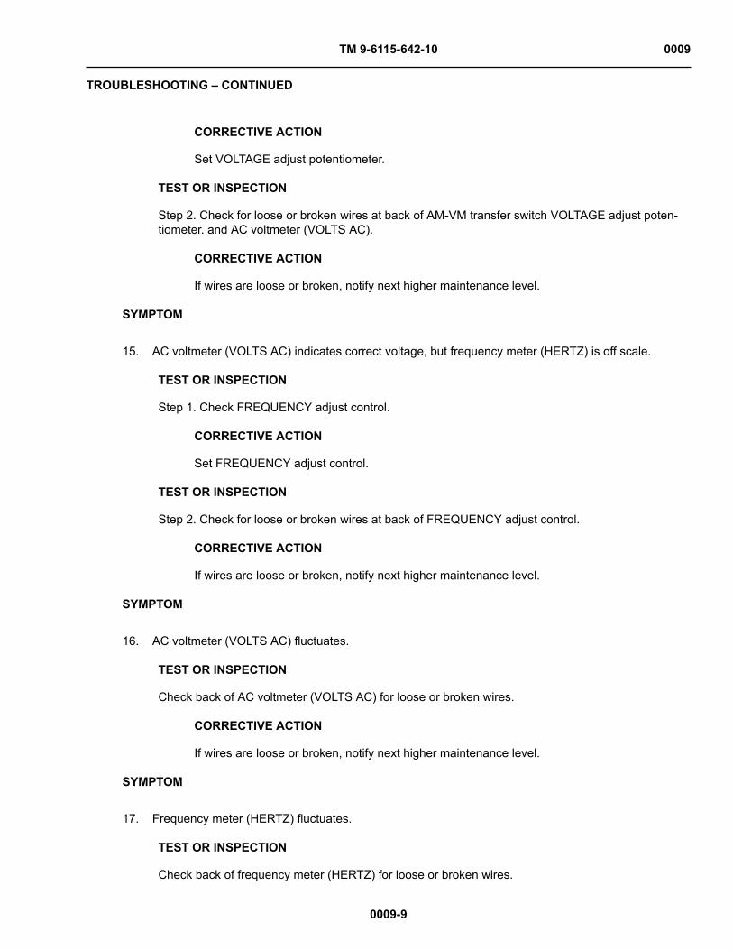
TM 9-6115-642-10 0009
TROUBLESHOOTING – CONTINUED
0009-9
CORRECTIVE ACTION
Set VOLTAGE adjust potentiometer.
TEST OR INSPECTION
Step 2. Check for loose or broken wires at back of AM-VM transfer switch VOLTAGE adjust poten-tiometer. and AC voltmeter (VOLTS AC).
CORRECTIVE ACTION
If wires are loose or broken, notify next higher maintenance level.
SYMPTOM
15. AC voltmeter (VOLTS AC) indicates correct voltage, but frequency meter (HERTZ) is off scale.
TEST OR INSPECTION
Step 1. Check FREQUENCY adjust control.
CORRECTIVE ACTION
Set FREQUENCY adjust control.
TEST OR INSPECTION
Step 2. Check for loose or broken wires at back of FREQUENCY adjust control.
CORRECTIVE ACTION
If wires are loose or broken, notify next higher maintenance level.
SYMPTOM
16. AC voltmeter (VOLTS AC) fluctuates.
TEST OR INSPECTION
Check back of AC voltmeter (VOLTS AC) for loose or broken wires.
CORRECTIVE ACTION
If wires are loose or broken, notify next higher maintenance level.
SYMPTOM
17. Frequency meter (HERTZ) fluctuates.
TEST OR INSPECTION
Check back of frequency meter (HERTZ) for loose or broken wires.

TM 9-6115-642-10 0009
TROUBLESHOOTING – CONTINUED
0009-10
CORRECTIVE ACTION
If wires are loose or broken, notify next higher maintenance level.
SYMPTOM
18. AC CIRCUIT INTERRUPTER light fails to light when AC CIRCUIT INTERRUPTER switch is closed.
TEST OR INSPECTION
Step 1. TEST AC CIRCUIT INTERRUPTER light by depressing.
CORRECTIVE ACTION
If light fails to light, refer to next higher maintenance level.
TEST OR INSPECTION
Step 2. Check load cables for proper connection. For proper connection of the load cables, refer toWP 0005, Installation of Load Cables.
CORRECTIVE ACTION
If correct go to Step 3.
TEST OR INSPECTION
Step 3. Ensure load does not exceed generator rating.
CORRECTIVE ACTION
Decrease load, if load is correct, refer to next higher maintenance level.
SYMPTOM
19. No voltage at the Convenience Receptacle.
TEST OR INSPECTION
Step 1. Open control panel and inspect circuit breaker on side of Ground Fault Circuit Interrupterdevice.
CORRECTIVE ACTION
If tripped, reset device. Check fuse on black wire of Ground Fault Circuit Interrupter for gener-ator sets, contract number DAAK01-88-D-D080.
TEST OR INSPECTION
Step 2. Check reset button for red band.

TM 9-6115-642-10 0009
TROUBLESHOOTING – CONTINUED
0009-11 / (12 blank)
CORRECTIVE ACTION
If red band is visible, push reset button. If Ground Fault Circuit Interrupter can not be reset,refer to next higher maintenance level.
END OF WORK PACKAGE


TM 9-6115-642-10
CHAPTER 4
OPERATOR MAINTENANCE INSTRUCTIONS
MEP-813A 10 kW, 400 Hz
GENERATOR SET, SKID MOUNTED, TACTICAL QUIET MEP-803A
10 kW, 60 Hz GENERATOR SET, SKID MOUNTED, TACTICAL QUIET
FOR

TM 9-6115-642-10
CHAPTER 4
OPERATOR MAINTENANCE INSTRUCTIONS
WORK PACKAGE INDEX
Title WP Sequence No.PMCS INTRODUCTION ................................................................................................................................... 0010PMCS, INCLUDING LUBRICATION INSTRUCTIONS ..................................................................................... 0011GENERATOR SET: INSPECTION AND SERVICE .......................................................................................... 0012BATTERIES: INSPECTION, SERVICING ......................................................................................................... 0013AIR CLEANER ASSEMBLY: INSPECTION, SERVICING ................................................................................ 0014COOLING SYSTEM: INSPECTION, SERVICING ............................................................................................ 0015FUEL TANK: SERVICING ................................................................................................................................. 0016FUEL FILTER/WATER SEPARATOR: INSPECTION, SERVICING .................................................................. 0017LUBRICATION SYSTEM: INSPECTION, SERVICING ..................................................................................... 0018

TM 9-6115-642-10 0010
0010-1
OPERATOR MAINTENANCE
PMCS INTRODUCTION
INITIAL SETUP:
References
WP 0002 (Figure 1)WP 0004, Figure 1WP 0009, Troubleshooting
References - cont'd
WP 0011, Table 1WP 0019, Equipment Inspection and MaintenanceWorksheet
GENERAL
To ensure that the generator set is ready for operation at all times, it must be inspected so that defects can be dis-covered and corrected before they result in serious damage or failure.
Before You Operate
Always keep in mind the CAUTIONS and WARNINGS. Perform your Before PMCS.
While You Operate
Always keep in mind the CAUTIONS and WARNINGS. Perform your During PMCS.
After You Operate
Be sure to perform your After PMCS.
If Your Equipment Fails to Operate
If your equipment does not perform as required, refer to WP 0009 under Troubleshooting for possible problems.Report any malfunctions or failures on the proper DA Form 2404, or refer to DA PAM 750-8.
PMCS PROCEDURES
NOTEFor general location of the items to be inspected in WP 0011, Table 1, refer to WP 0002, Fig-ure 1, and WP 0004, Figure 1 through Figure 3.
Purpose of PMCS Table
Preventive Maintenance Checks and Services (WP 0011, Table 1) list the inspections and care of your equipmentrequired to keep it in good operating condition.
Warnings, Cautions, and Notes
Always observe the WARNINGS, CAUTIONS, and NOTES appearing in your PMCS table. Warnings and cau-tions appear before applicable procedures. You must observe WARNINGS to prevent serious injury to yourselfand others. You must observe CAUTIONS to prevent your equipment from being damaged. You must observe NOTES to ensure procedures are performed properly.

TM 9-6115-642-10 0010
GENERAL – CONTINUED
0010-2
Explanation of Table Entries
The PMCS table is divided into five columns. Each column is explained in the following paragraphs.
Item No. Column. Numbers in this column are for reference. When completing DA Form 2404 (EquipmentInspection and Maintenance Worksheet), include the item number for the check/service indicating a fault. Itemnumbers also appear in the order that you must do checks and services for the intervals listed.
Interval Column. This column tells you when you must do the procedure described in the procedure column."BEFORE" procedures must be done before you operate the equipment for its intended mission. "DURING" pro-cedures must be done during the time you are operating the equipment for its intended mission. "AFTER" proce-dures must be done immediately after you have operated the equipment. Perform "WEEKLY" procedures at thelisted interval.
Item to be Checked or Service Column. This column lists the location and the item to be checked or serviced.The item location is underlined.
Procedure Column. This column gives the procedure for checking or servicing the item listed in the location,item to check/service column. You must perform the procedure to know if the power unit or power plant is readyor available for its intended mission or operation. You must do the procedure at the time stated in the interval col-umn.
Equipment Not Ready/Available if: Column. Information in this column tells you what faults will keep yourequipment from being capable of performing its primary mission. If you perform checks or services that showfaults listed in this column, do not operate the equipment.
Other Table Entries
Be sure to observe all special information and notes that appear in your table.
Special Instructions
Preventive maintenance is not limited to performing the checks and services listed in the PMCS Table. Coveringunused receptacles, stowing unused accessories and performing other routine procedures such as equipmentinventory, cleaning components, and touch-up painting are not listed in the table. These are things you should doany time you see that they need to be done. If a routine check is listed in the PMCS Table, it is because experi-ence has shown that problems may occur with this item. Take along tools and cleaning cloths needed to performthe required checks and services. Use the information in the following paragraphs to help you identify problems atany time and to help identify potential problems before and during checks and services.
1. Keep the generator set clean. Dirt, grease, and oil get in the way and may cover up a serious problem. Usecleaning solvent to clean metal surfaces.
2. Use soap and water to clean rubber or plastic parts and material.3. Check all bolts, nuts, and screws to make sure they are not loose, missing, bent, or broken. Do not try to
check them with a tool, but look for chipped paint, bare metal, or rust around bolt heads. If you find oneloose, report it to the next-higher level of maintenance.
4. Inspect welds for loose or chipped paint, rust, or gaps where parts are welded together. If a broken weld isfound, report it to the next-higher level of maintenance.
5. Inspect electrical wires, connectors, terminals, and receptacles for cracked or broken insulation, bare wires,and loose or broken connectors. Tighten loose connectors. Examine terminals and receptacles for service-ability. If deficiencies are found, report them to the next-higher level of maintenance.
6. Inspect hoses and fluid lines. Look for wear, damage, and leaks. Make sure that clamps and fittings aretight. Wet spots and stains around a fitting or connector can mean a leak. If a leak comes from a loose con-nector, or if something is broken or worn out, report it to the next-higher level of maintenance.

TM 9-6115-642-10 0010
GENERAL – CONTINUED
0010-3 / (4 blank)
Leakage Definitions
You must know how fluid leakage affects the status of your equipment. The following are definitions of the types/classes of leakage you need to know to be able to determine the status of your equipment. Learn and be familiarwith them. When in doubt, notify your supervisor.
Table 1. Leakage Definitions.
LEAKAGECLASS
LEAKAGE DEFINITION
Class I Seepage of fluid (as indicated by wetness or discoloration) not great enough toform drops
Class II Leakage of fluid great enough to form drops, but not enough to cause drops to dripfrom the item being checked/inspected.
Class III Leakage of fluid (other than fuel) greater than three drops per minute that fall fromthe item being inspected.
Operation of Generator Set with Minor Leaks
a. Consider the equipment's capacity for the fluid that is leaking. If the capacity is small, the fluid level maysoon become too low for continued operation. If in doubt, notify your supervisor.
b. Check the fluid level more often than required in the PMCS Table. Add fluid as needed.c. All leaks should be reported to the next higher level of maintenance.
Corrosion Prevention and Control (CPC)
CPC of Army material is of continuing concern. It is important that any corrosion problems with the equipment bereported so that the problem can be corrected and improvements can be made to prevent the problem in futureitems. Although corrosion is typically associated with rusting of metals, it can also include deterioration of othermaterials, such as rubber and plastic. Unusual cracking, softening, swelling, or breaking of these materials maybe a corrosion problem. If a corrosion problem is identified, it can be reported using Standard Form 368, ProductQuality Deficiency Report. Use of key words such as "corrosion," "rust," "deterioration," or "cracking" will ensurethat the information is identified as a CPC problem. The form should be submitted to the address specified in DAPAM 750-8.
Removal of Assemblies/Equipment to Perform PMCS
There is no requirement to remove assemblies/equipment prior to performing the PMCS.
END OF WORK PACKAGE


TM 9-6115-642-10 0011
0011-1
OPERATOR MAINTENANCE
PMCS, INCLUDING LUBRICATION INSTRUCTIONS
INITIAL SETUP:
Tools and Special Tools
Generator Mechanical Tool Kit P/N (S25885) (NSN 4910-01-490-6453)
Personnel Required
One (1): Power Generation Mechanic (91D)
References
LO 9-6115-642-12WP 0019, Equipment Inspection and MaintenanceWorksheet
Equipment Condition
Grounded, Off & Operational (Stopping Procedure,WP 0005)
Table 1. Operator Preventive Maintenance Checks and Services.
ITEMNO. INTERVAL
ITEM TO BECHECKED OR
SERVICED PROCEDURE
EQUIPMENTNOT READY/
AVAILABLE IF:
NOTEThe generator set can be operated continuously at any load from no load up to andincluding rated load; However, at light loads (less than 25% of set rating) and oily residue(unburned fuel oil) may occasionally be noticed in the exhaust system outlet and aroundconnection joints in the exhaust system. This residue is caused by the inability of the fuelinjection system to consistently meter the small amount of fuel required to operate at theselow load levels. It is not a defect in the fuel system. The oily residue could affect engine per-formance and create a cosmetic problem on and around the generator set. Operation atrated load will bum off this oily residue. The length of time required at rated load dependson the amount of residue. The muffler may also need to be removed and cleaned if exces-sive build up occurs. This oily residue can be prevented by increasing the electrical load onthe set.
NOTEIf the equipment must be kept in continuous operation, check and service only those Itemsthat can be checked and serviced without disrupting operations. Complete all checks andservices when equipment is shut down.
1 Before Generator SetExterior: Housing
Operator1. Check door panels, hinges, and latches for
damage, loose, or corroded items.
Cannot secure door.
2. Inspect air intake and exhaust grills fordebris.
2 Before Generator SetExterior: Identifi-cation Plates
Operator
Check to ensure identification plates are secure.

TM 9-6115-642-10 0011
Table 1. Operator Preventive Maintenance Checks and Services – Continued
0011-2
ITEMNO. INTERVAL
ITEM TO BECHECKED OR
SERVICED PROCEDURE
EQUIPMENTNOT READY/
AVAILABLE IF:
3 Before Generator SetExterior: SkidBase
Operator
Inspect skid base for cracks and/or corrosion.
Skid base is crackedor shows signs ofstructural damage.
4 Before Generator SetExterior: Acousti-cal Materials
Operator
Inspect to ensure acoustical materials, located inthe grill areas and under the engine are secure,not damaged, or missing.
5 Before Engine Assem-bly
Operator
WARNINGWith any access door open,the noise level of this gen-erator set when operatingcould cause hearing dam-age. Hearing protectionmust be worn when workingnear the generator set whilerunning.
WARNINGThe fuels in this genera-tor set are highly explo-sive. Do not smoke or useopen flame when perform-ing maintenance. Flamesand explosion could resultin severe personal injury ordeath.
Inspect for loose, damaged, or missing hard-ware.
Any loose, dam-aged, or missinghardware.
6 Before Engine Assem-bly: Fuel System
Operator
Inspect for leaks, damage, loose, or missinghardware.
Any fuel leaks, dam-aged, or missingparts.
7 Before Engine Assem-bly: Fuel Fil-ter/Water Sepa-rator
Operator1. Inspect for leaks, cracks, damage, proper
mounting, loose, or missing hardware.
Any fuel leaks.
2. Drain water from fuel filter/water separatorWP 0017, Servicing.
Water not drained.
8 Before Engine Assem-bly: LubricationSystem
Operator1. Inspect for leaks, damage, loose, or missing
parts.
Class III leaks, dam-age, loose, or miss-ing parts.

TM 9-6115-642-10 0011
Table 1. Operator Preventive Maintenance Checks and Services – Continued
0011-3
ITEMNO. INTERVAL
ITEM TO BECHECKED OR
SERVICED PROCEDURE
EQUIPMENTNOT READY/
AVAILABLE IF:2. Inspect oil level. Oil level is low.3. Inspect for contamination. Oil shows signs of
contamination.
9 Before Cooling System:Radiator
Operator
WARNINGCooling system operates athigh temperatures. Personalinjury or death from burnsor scalding could result fromcontact with high pressuresteam and/or liquid.
Inspect for leaks, damage, loose, or missingparts.
Class III leaks ormissing radiatorcap.
10 Before Cooling System:Hoses
Operator
Inspect for leaks, cracks, or missing parts.
Class III leaks ormissing clamps orhoses.
11 Before Cooling System:Cooling Fan
Operator1. Inspect for obstruction, damage, or loose-
ness.
Damaged or loose.
2. Inspect for unusual noise in fan area. Unusual noise fromarea.
12 Before Cooling System:Fan Belt
Operator
Inspect for cracks, fraying or looseness.
Broken or missingbelt.
13 Before Cooling System:Overflow Bottle
Operator
Inspect for proper mounting, leaks, or missinghardware.
Class III leaks ormissing hardware.

TM 9-6115-642-10 0011
Table 1. Operator Preventive Maintenance Checks and Services – Continued
0011-4
ITEMNO. INTERVAL
ITEM TO BECHECKED OR
SERVICED PROCEDURE
EQUIPMENTNOT READY/
AVAILABLE IF:
14 Before Exhaust/IntakeSystem: ExhaustSystem
Operator
WARNINGExhaust discharge con-tains deadly gases. Donot operate generator setin enclosed area unlessexhaust discharge is prop-erly vented outside. Severepersonal injury or death dueto carbon monoxide poison-ing could result.
Inspect for leaks, corrosion, and missing parts. Leaks, damaged, ormissing parts.
15 Before Exhaust/IntakeSystem: AirCleaner Assem-bly
Operator1. Inspect for loose, damaged, or missing parts.
Loose or missingparts
2. Inspect restriction indicator for clogged aircleaner element.
Clogged air cleanerelement.
16 Before GroundingRod Assem-bly: Ground RodCable and Con-nections
Operator
WARNINGNever attempt to start thegenerator set if it is not prop-erly grounded. Failure toobserve this warning couldresult in serious injury ordeath by electrocution.
Inspect for damage, corrosion, and loose con-nections.
Damaged, corroded,or loose connec-tions.
17 Before Electrical Sys-tem: Batteries
Operator
WARNINGBattery acid will cause burnsto unprotected skin.

TM 9-6115-642-10 0011
Table 1. Operator Preventive Maintenance Checks and Services – Continued
0011-5
ITEMNO. INTERVAL
ITEM TO BECHECKED OR
SERVICED PROCEDURE
EQUIPMENTNOT READY/
AVAILABLE IF:
WARNINGBatteries give off flammablegas. Do not smoke or useopen flame when performingmaintenance. Flames andexplosion could result in per-sonal injury or death.
WARNINGDC voltages are present atgenerator set electrical com-ponents even with gener-ator set shut down. Avoidgrounding self when touch-ing any electrical compo-nents. Failure to observethis warning can result inpersonal injury.
Inspect for secure mounting. Broken or missingmounting hardware.
18 Before Electrical Sys-tem: BatteryCables
Operator
Inspect for corrosion, damage, loose connec-tions, or missing parts.
Damaged, loose, ormissing parts.
19 Before Electrical Sys-tem: Output BoxAssembly
Operator1. Inspect cables for damage or loose connec-
tions.
Damaged, loose, ormissing parts.
2. Inspect output terminals for damage or miss-ing hardware.
Damaged or missinghardware.
20 Before Control BoxAssembly: Con-trols and Indica-tors
Operator
Inspect for damage or missing parts.
Damaged or missingparts.
21 Before Control BoxAssembly: Con-trol Box Harness
Operator
WARNINGHigh Voltage is producedwhen this generator set is inoperation. Improper opera-tion could result in personalinjury or death by electrocu-tion.
Inspect for damage and looseness. Damaged or loose.

TM 9-6115-642-10 0011
Table 1. Operator Preventive Maintenance Checks and Services – Continued
0011-6
ITEMNO. INTERVAL
ITEM TO BECHECKED OR
SERVICED PROCEDURE
EQUIPMENTNOT READY/
AVAILABLE IF:
22 During Generator SetExterior: Housing
Operator
NOTEIf the equipment must bekept in continuos opera-tion, check and service onlythose items that can bechecked and serviced with-out disrupting operations.Complete all checks andservices when equipment isshut down.
Check door panels, hinges, and latches for dam-age, loose, or corroded items.
Cannot secure door.
23 During Engine Assem-bly
Operator
WARNINGWith any access door open,the noise level of this gen-erator set when operatingcould cause hearing dam-age. Hearing protectionmust be worn when workingnear the generator set whilerunning.
WARNINGThe fuels in this genera-tor set are highly explo-sive. Do not smoke or useopen flame when perform-ing maintenance. Flamesand explosion could resultin severe personal injury ordeath.
Inspect for loose, damaged or missing hardware. Any loose, damagedor missing hard-ware.
24 During Engine Assem-bly: Fuel System
Operator
Inspect for leaks, damage, loose, or missinghardware.
Any fuel leaks, dam-age, loose, or miss-ing parts.

TM 9-6115-642-10 0011
Table 1. Operator Preventive Maintenance Checks and Services – Continued
0011-7
ITEMNO. INTERVAL
ITEM TO BECHECKED OR
SERVICED PROCEDURE
EQUIPMENTNOT READY/
AVAILABLE IF:
25 During Engine Assem-bly: LubricationSystem
Operator1. Inspect for leaks, damage or missing parts.
Class III leaks, dam-age, loose, or miss-ing parts.
2. Inspect for contamination. Oil shows signs ofcontamination.
26 During CoolingSystem:CoolingFan
Operator1. Inspect for obstruction, damage, or loose-
ness.
Damaged or loose.
2. Inspect for unusual noise in fan area. Unusual noise fromarea.
27 During Cooling System:Overflow Bottle
Operator
Inspect for proper mounting, leaks, or missinghardware.
Class III leaks ormissing hardware.
28 During GroundingRod Assem-bly: Ground RodCable and Con-nections
Operator
Inspect for damage, corrosion, and loose con-nections.
Damaged, corroded,or loose connec-tions.
29 During Control BoxAssembly: Con-trols and Indica-tors
Operator
WARNINGHigh Voltage is producedwhen this generator set is inoperation. Improper opera-tion could result in personalinjury or death by electrocu-tion.
Inspect indicators are operating properly. Indicators are notoperating properly.
30 After Generator SetExterior: Housing
Operator
NOTEIf the equipment must bekept in continuos opera-tion, check and service onlythose items that can bechecked and serviced with-out disrupting operations.Complete all checks andservices when equipment isshut down.
Check door panels, hinges, and latches for dam-age, loose, or corroded items.
Cannot secure door.

TM 9-6115-642-10 0011
Table 1. Operator Preventive Maintenance Checks and Services – Continued
0011-8
ITEMNO. INTERVAL
ITEM TO BECHECKED OR
SERVICED PROCEDURE
EQUIPMENTNOT READY/
AVAILABLE IF:
31 After Generator SetExterior: Identifi-cation Plates
Operator
Check to ensure identification plates are secure.
32 After Generator SetExterior: SkidBase
Operator
Inspect skid base for cracks and/or corrosion.
Skid base is crackedor shows signs ofstructural damage.
33 After Engine Assem-bly
Operator
WARNINGThe fuels in this genera-tor set are highly explo-sive. Do not smoke or useopen flame when perform-ing maintenance. Flamesand explosion could resultin severe personal injury ordeath.
Inspect for loose, damaged or missing hardware. Any loose, damagedor missing hard-ware.
34 After Engine Assem-bly: Fuel System
Operator
Inspect for leaks, damage, loose, or missinghardware.
Any fuel leaks, dam-age, loose, or miss-ing parts.
35 After Engine Assem-bly: Fuel Fil-ter/Water Sepa-rator
Operator1. Inspect for leaks, cracks, damage, proper
mounting, loose, or missing parts.
Any fuel leaks.
2. Drain water from fuel filter/water separatorWP 0017, Sevicing.
Water not drained.
36 After Engine Assem-bly: LubricationSystem
Operator1. Inspect for leaks, damage or missing parts.
Class III leaks, dam-age, loose, or miss-ing parts.
2. Inspect oil level. Oil level is low.3. Inspect for contamination. Oil shows signs of
contamination.

TM 9-6115-642-10 0011
Table 1. Operator Preventive Maintenance Checks and Services – Continued
0011-9 / (10 blank)
ITEMNO. INTERVAL
ITEM TO BECHECKED OR
SERVICED PROCEDURE
EQUIPMENTNOT READY/
AVAILABLE IF:
37 After Cooling System:Radiator
Operator
WARNINGCooling system operates athigh temperatures. Personalinjury or death from burnsor scalding could result fromcontact with high pressuresteam and/or liquid.
Inspect for leaks, damage, loose, or missingparts.
Class III leaks ormissing radiatorcap.
38 After Cooling System:Hoses
Operator
Inspect for leaks, cracks, or missing parts.
Class III leaks ormissing clamps orhoses.
39 After Cooling System:Fan Belt
Operator
Inspect for cracks, fraying or looseness.
Broken or missingbelt.
40 After Control BoxAssembly: Con-trols and Indica-tors
Operator
Inspect for damage or missing parts.
Damaged or missingparts.
MANDATORY REPLACEMENT PARTS
There are no replacement parts required for these PMCS procedures.
LUBRICATION INSTRUCTIONS
Refer to LO 9-6115-642-12 for lubrication information.
END OF WORK PACKAGE


TM 9-6115-642-10 0012
0012-1 / (2 blank)
OPERATOR MAINTENANCE
GENERATOR SET: INSPECTION AND SERVICE
INITIAL SETUP:
Not Applicable
GENERATOR SET INSPECTION AND SERVICE
INTRODUCTION
This section contains operator maintenance procedures. Deficiencies noted during inspection which are beyondthe maintenance scope of the operator shall be reported to next higher maintenance level.
END OF WORK PACKAGE


TM 9-6115-642-10 0013
0013-1
OPERATOR MAINTENANCE
BATTERIES: INSPECTION, SERVICING
INITIAL SETUP:
Tools and Special Tools
Generator Mechanical Tool Kit P/N (S25885) (NSN 4910-01-490-6453)
Materials/Parts
Protective Clothing P/N foo mtrlpart partno Personnel Required
One (1): Power Generation Mechanic (91D)
References
WP 0005, Stopping Procedure Equipment Condition
Grounded, Off & Operational
WARNINGBattery acid will cause burns to unprotected skin.
WARNINGBatteries give off flammable gas. Do not smoke or use open flame when performing mainte-nance. Flames and explosion could result in personal injury or death.
INSPECTION
1. Shut down generator set, refer to WP 0005, Stopping Procedure.
2. Open engine access door.
3. Inspect for damaged battery case, corrosion, and loose connections on terminal cable, and damaged ormissing battery caps.
WARNINGBatteries give off flammable gas. Do not smoke or use open flame when performingmaintenance. Flames and explosion could result in personal injury or death.
4. Remove battery caps.
CAUTIONElectrolyte level must cover battery plates in all cells. Failure to observe this caution cancause damage to the battery.
NOTEElectrolyte level should be at bottom of each cap cylinder.
5. Inspect electrolyte level.
TM 9-6115-642-10 0013
INSPECTION – CONTINUED
0013-2
6. Perform service procedures if required.
7. Install battery caps.
8. Close engine access door.
END OF TASK
SERVICING
1. Shut down generator set, refer to WP 0005, Stopping Procedure.
2. Open engine access door.
WARNINGBatteries give off flammable gas. Do not smoke or use open flame when performingmaintenance. Flames and explosion could result in personal injury or death.
3. Remove battery caps.
NOTEElectrolyte level should be at bottom of each cap cylinder.
4. Add distilled water to each battery cell as required.
5. Replace battery caps.
6. Close engine access door.
7. If necessary contact next higher maintenance level to clean or replace batteries or battery terminals.
END OF TASK
END OF WORK PACKAGE

TM 9-6115-642-10 0014
0014-1
OPERATOR MAINTENANCE
AIR CLEANER ASSEMBLY: INSPECTION, SERVICING
INITIAL SETUP:
Tools and Special Tools
Generator Mechanical Tool Kit P/N (S25885) (NSN 4910-01-490-6453)
Personnel Required
One (1): Power Generation Mechanic (91D)
References
WP 0005, Stopping Procedure Equipment Condition
Grounded, Off & Operational
Figure 1. Air Cleaner Element Replacement.
INSPECTION
1. Shut down generator set, refer to WP 0005, Stopping Procedure.

TM 9-6115-642-10 0014
INSPECTION – CONTINUED
0014-2
2. Open left side engine access door.
3. Inspect air cleaner housing (Figure 1, Item 5) for dents, corrosion, missing hardware and other damage.
4. Open right side engine access door and inspect air cleaner restriction indicator for indication of a clogged aircleaner element.
5. Close engine access door.
END OF TASK
SERVICING
1. Shut down generator set, refer to WP 0005, Stopping Procedure.
2. Open left side engine access door.
3. Loosen wing nut clamp (1) and remove end cap (2) on air cleaner housing (5).
4. Remove wing nut (3) and air cleaner element (4). If fouled, discard air cleaner element.
5. Inspect inside of air cleaner housing (5) for debris. Wipe air cleaner housing interior with clean lint-free cloth.
6. Install air cleaner element (4), wing nut (3), end cap (2) and tighten wing nut (1).
7. Close engine compartment access door.
END OF TASK
END OF WORK PACKAGE

TM 9-6115-642-10 0015
0015-1
OPERATOR MAINTENANCE
COOLING SYSTEM: INSPECTION, SERVICING
INITIAL SETUP:
Tools and Special Tools
Generator Mechanical Tool Kit P/N (S25885) (NSN 4910-01-490-6453)
Materials/Parts
Inhibitor P/N MIL-A-53009Antifreeze P/N MIL-A-46153Antifreeze P/N MIL-A-11755
Personnel Required
One (1): Power Generation Mechanic (91D) References
WP 0005, Stopping Procedure Equipment Condition
Grounded, Off & Operational
INSPECTION
1. Shut down generator set, refer to WP 0005, Stopping Procedure.
2. Open both engine access doors.
WARNINGCooling system operates at high temperatures. Personal injury or death from burns orscalding could result from contact with high pressure steam and/or liquid.
3. Check radiator for dirt, leaves, insects, etc. blocking air flow.
4. Check radiator and hoses for leaks, loose connections, loose mounting, corrosion, chafing and missingparts.
5. Check coolant level in coolant recovery (overflow) bottle.
6. Close engine compartment access doors.
END OF TASK
SERVICING
WARNINGCooling system operates at high temperatures. Personal injury or death from burns or scald-ing could result from contact with high pressure steam and/or liquid.
1. Shut down generator set, refer to WP 0005, Stopping Procedure.
2. Open right side engine access door.
3. Remove coolant recovery (overflow) bottle cap.
4. Fill coolant recovery (overflow) bottle to HOT line if coolant is hot or to COLD line if coolant is cold, withproper coolant/antifreeze in accordance with Table 1.
5. Install coolant recovery (overflow) bottle cap. Close right side engine access door.

TM 9-6115-642-10 0015
SERVICING – CONTINUED
0015-2
Table 1. Coolant.
AMBIENT TEMPERATURE RADIATOR COOLANT RATIO
+40 to +120 °F (+4 to +49 °C) Water: MIL-A-53009 Inhibitor,Corrosion
35:1
-25 to +120 °F (-32 to +49 °C) Water: MIL-A-46153Antifreeze
1:1
-25 to +120 °F (-32 to +49 °C) MIL-A-11755 Antifreeze NA
END OF TASK
END OF WORK PACKAGE

TM 9-6115-642-10 0016
0016-1
OPERATOR MAINTENANCE
FUEL TANK: SERVICING
INITIAL SETUP:
Tools and Special Tools
Generator Mechanical Tool Kit P/N (S25885) (NSN 4910-01-490-6453)
Materials/Parts
Disel Fuel P/N W-F 800 Grade DF-2 JP4, JP5, JP8Disel Fuel P/N W-F 800 Grade DF-1 JP4, JP5, JP8Disel Fuel P/N W-F 800 Grade DF-1Disel Fuel P/N W-F 800 Grade DF-A
Personnel Required
One (1): Power Generation Mechanic (91D) References
WP 0005, Stopping Procedure Equipment Condition
Grounded, Off & Operational
SERVICING
WARNINGThe fuels in this generator set are highly explosive. Do not smoke or use open flame whenperforming maintenance. Flames and explosion could result in severe personal injury ordeath.
CAUTIONUse only specified diesel fuel to service the fuel tank, refer to Table 1. Otherwise, equipmentdamage could result, if improper fuel is used.
1. Shut down generator set, refer to WP 0005, Stopping Procedure.
2. Remove fuel cap.
3. Remove strainer, clean as necessary and reinstall.
NOTEFuel tank holds 9 gallons (34 liters).
4. Add diesel fuel to fuel tank.
5. Install fuel cap.
Diesel Fuel
Table 1. Fuel.
AMBIENT TEMPERATURE DIESEL FUEL
+20 to +120 °F (-7 to +49 °C) W-F-800 GRADE DF-2 JP4, JP5, JP8
0 to +20 °F (-17 to +7 °C) W-F-800 GRADE DF-1 JP4, JP5, JP8

TM 9-6115-642-10 0016
SERVICING – CONTINUED
Table 1. Fuel. – Continued
0016-2
AMBIENT TEMPERATURE DIESEL FUEL
-25 to 0 °F (-32 to -17 °C) W-F-800 GRADE DF-1
-25 to 0 °F (-32 to -17 °C) W-F-800 GRADE DF-A
END OF TASK
END OF WORK PACKAGE

TM 9-6115-642-10 0017
0017-1
OPERATOR MAINTENANCE
FUEL FILTER/WATER SEPARATOR: INSPECTION, SERVICING
INITIAL SETUP:
Tools and Special Tools
Generator Mechanical Tool Kit P/N (S25885) (NSN 4910-01-490-6453)
Materials/Parts
Suitable Container to Drain Contaminants P/N Personnel Required
One (1): Power Generation Mechanic (91D)
References
WP 0005, Stopping Procedure Equipment Condition
Grounded, Off & Operational
Figure 1. Draining Fuel Filter/Water Separator.

TM 9-6115-642-10 0017
0017-2
INSPECTION
1. Shut down generator set, refer to WP 0005, Stopping Procedure.
2. Open left side engine access door.
3. Inspect fuel filter/water separator assembly (Figure 1) for proper mounting, cracks, dents, leaks, loose fuellines and other damage.
4. Close left engine access door.
END OF TASK
SERVICING
1. Shut down generator set, refer to WP 0005, Stopping Procedure.
2. Rotate MASTER SWITCH to PRIME & RUN.
3. Open left side engine access door.
4. Open fuel drain cock (1) on fuel filter/water separator housing (2) and drain contaminants into a suitablecontainer.
5. Close drain cock (1).
6. Close left side engine access door.
7. Rotate MASTER SWITCH to OFF.
END OF TASK
END OF WORK PACKAGE
TM 9-6115-642-10 0018
0018-1 / (2 blank)
OPERATOR MAINTENANCE
LUBRICATION SYSTEM: INSPECTION, SERVICING
INITIAL SETUP:
Tools and Special Tools
Generator Mechanical Tool Kit P/N (S25885) (NSN 4910-01-490-6453)
Personnel Required
One (1): Power Generation Mechanic (91D)
References
WP 0005, Stopping ProcedureLO 9-6115-642-12
Equipment Condition
Grounded, Off & Operational
INSPECTION
1. Shut down generator set, refer to WP 0005, Stopping Procedure.
2. Open both engine access doors.
3. Inspect engine assembly for oil leaks.
4. Check for damage, proper mounting, or missing parts.
5. Check engine crankcase oil level. Refer to LO 9-6115-642-12.
6. Close both engine access doors.
END OF TASK
SERVICING
1. Shut down generator set, refer to WP 0005, Stopping Procedure.
2. Open left engine access door.
3. Remove oil filler cap.
4. Add oil to engine crankcase. Refer to LO 9-6115-642-12.
5. Install oil filler cap.
6. Close left engine access door.
END OF TASK
END OF WORK PACKAGE


TM 9-6115-642-10
CHAPTER 5
OPERATOR SUPPORTING INFORMATION
MEP-813A 10 kW, 400 Hz
GENERATOR SET, SKID MOUNTED, TACTICAL QUIET MEP-803A
10 kW, 60 Hz GENERATOR SET, SKID MOUNTED, TACTICAL QUIET
FOR

TM 9-6115-642-10
CHAPTER 5
OPERATOR SUPPORTING INFORMATION
WORK PACKAGE INDEX
Title WP Sequence No.REFERENCES .................................................................................................................................................. 0019COMPONENTS OF END ITEM (COEI) AND BASIC ISSUE ITEMS (BII) LISTS ............................................. 0020ADDITIONAL AUTHORIZATION LIST (AAL) ................................................................................................... 0021EXPENDABLE AND DURABLE ITEMS LIST .................................................................................................. 0022

TM 9-6115-642-10 0019
0019-1 / (2 blank)
OPERATOR MAINTENANCE
REFERENCES
SCOPE
This work package lists all forms, field manuals, technical manuals and miscellaneous publications referenced inthis manual.
FORMS
AFTO Form 22 Recommending Improvements to Technical PublicationsDA Form 2028 Recommended Changes to Publications and Blank FormsDA Form 2028-2 Recommended Changes to Equipment Technical PublicationsDA Form 2404 Equipment Inspection and Maintenance WorksheetDA Form 2408-9 Equipment Control LogNAVMC 10772 Reporting Errors and Recommending Improvements to Technical PublicationsSF 368 Quality Deficiency Report
FIELD MANUALS
FM 3-3 NBC Contamination AvoidanceFM 3-4 NBC ProtectionFM 3-5 NBC DecontaminationFM 4-25.11 First AidFM 20-31 Electric Power Generation in the Field
TECHNICAL MANUALS
TM 4700-15/1 Marine Corps Forms
MISCELLANEOUS PUBLICATIONS
AFR 66-1 Air Force Maintenance Forms and RecordsDA PAM 738-750 The Army Maintenance Management System (TAMMS)LO 9-6115-642-12 Lubrication OrderMCO 4855.10 Quality and Deficiency ReportingMIL-STD-12 Military Standard AbbreviationsTB 9-6115-642-24 Warranty Technical Bulletin
END OF WORK PACKAGE


TM 9-6115-642-10 0020
0020-1
OPERATOR MAINTENANCE
COMPONENTS OF END ITEM (COEI) AND BASIC ISSUE ITEMS (BII) LISTS
INTRODUCTION
Scope
This work package lists COEI and BII for the generator set to help you inventory items for safe and efficient opera-tion of the equipment.
General
The COEI and BII information is divided into the following lists:
Components of End Item (COEI)
This list is for information purposes only and is not authority to requisition replacements. These items are part ofthe generator set. As part of the end item, these items must be with the end item whenever it is issued or trans-ferred between property accounts. Items of COEI are removed and separately packaged for transportation orshipment only when necessary. Illustrations are furnished to help you find and identify the items.
Basic Issue Items (BII)
These essential items are required to place the generator set in operation, operate it, and to do emergencyrepairs. Although shipped separately packaged, BII must be with the generator set during operation and whenit is transferred between property accounts. Listing these items is your authority to request/requisition them forreplacement based on authorization of the end item by the TOE/MTOE. Illustrations are furnished to help you findand identify the items.
Explanation of Columns in the COEI List and BII List
Column (1), Illus Number, gives you the number of the item illustrated.
Column (2), National Stock Number, identifies the stock number of the item to be used for requisitioning purposes.
Column (3), Description, Part Number, and CAGEC, identifies the Federal item name (in all capital letters) fol-lowed by a minimum description when needed. The stowage location of COEI and BII is also included in this col-umn. The last line below the description is the CAGEC (Commercial and Government Entity Code) (in parenthe-ses) and the part number.
Column (4), Usable on Code, gives you a code if the item you need is not the same for different models of equip-ment.
Column (5), U/I (unit of issue), indicates how the item is issued for the National Stock Number shown in column(2).
Column (6), Qty Rqr, indicates the quantity required.

TM 9-6115-642-10 0020
0020-2
Table 1. Component of End Items (COEI) List.
(1) (2) (3) (4) (5) (6)
ILLUSNUMBER
NATIONAL STOCKNUMBER (NSN) DESCRIPTION, PART NUMBER/(CAGEC)
USABLEON
CODE U/IQTYRQR
0000-00-000-0000 NOT APPLICABLE -
Figure 1. Basic Issue Items.
Table 2. Basic Issue Items (BII).
(1) (2) (3) (4) (5) (6)
ILLUSNUMBER
NATIONAL STOCKNUMBER (NSN) DESCRIPTION, PART NUMBER/(CAGEC)
USABLEON
CODE U/IQTYRQR
1 TECHNICAL MANUAL, TM 9-6115-642-10 EA 1
2 LUBRICATION ORDER, LO 9-6115-642-12 EA 1
3 WARRANTY TECHNICAL BULLETIN, TB9-6115-642-24
EA 1
END OF WORK PACKAGE

TM 9-6115-642-10 0021
0021-1 / (2 blank)
OPERATOR MAINTENANCE
ADDITIONAL AUTHORIZATION LIST (AAL)
INTRODUCTION
Scope
This work package lists additional items you are authorized for the support of the generator set.
General
This list identifies items that do not have to accompany the generator set and that do not have to be turned in withit. These items are all authorized to you by CTA, MTOE, TDA, or JTA.
Explanation of Entries in the AAL
Column (1) National Stock Number (NSN). Identifies the stock number of the item to be used for requisitioningpurposes.
Column (2) Description, Part Number/(CAGEC). Identifies the Federal item name (in all capital letters) followed bya minimum description when needed. The last line below the description is the part number and the Commercialand Government Entity Code (CAGEC) (in parentheses).
Column (3) Usable On Code. When applicable, gives you a code if the item you need is not the same for differentmodels of equipment.
Column (4) U/I. Unit of Issue (U/I) indicates the physical measurement or count of the item as issued per theNational Stock Number shown in column (1).
Column (5) Qty Recm. Indicates the quantity recommended.
Table 1. Additional Authorization List.
(1) (2) (3) (4) (5)
NATIONAL STOCKNUMBER (NSN) DESCRIPTION, PART NUMBER/(CAGEC)
USABLEON
CODE U/IQTY
RECM2910-00-066-1235 ADAPTER, CONTAINER
13211E7541 (97403)EA 1
7240-00-222-3088 CAN, GASOLINE, MILITARY42-D-1280 (80372)
EA 1
4210-00-270-4512 EXTINGUISHER, FIRE, CARBON DIOXIDEO-E-91O (81348)
EA 1
5120-01-013-1676 SLIDE HAMMER, GROUND13226E7741 (97403)
EA 1
7240-00-177-6154 SPOUT, CAN, FLEXIBLEMIL-S-1285 (81349)
EA 1
END OF WORK PACKAGE

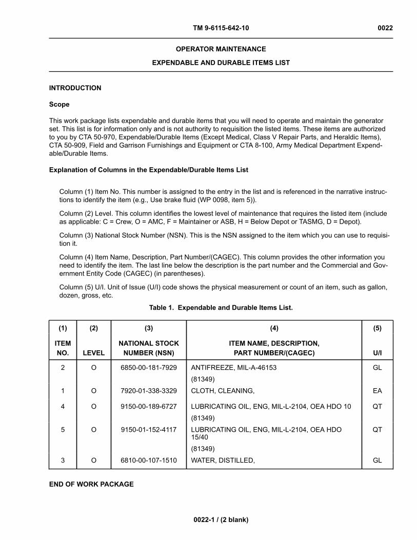
TM 9-6115-642-10 0022
0022-1 / (2 blank)
OPERATOR MAINTENANCE
EXPENDABLE AND DURABLE ITEMS LIST
INTRODUCTION
Scope
This work package lists expendable and durable items that you will need to operate and maintain the generatorset. This list is for information only and is not authority to requisition the listed items. These items are authorizedto you by CTA 50-970, Expendable/Durable Items (Except Medical, Class V Repair Parts, and Heraldic Items),CTA 50-909, Field and Garrison Furnishings and Equipment or CTA 8-100, Army Medical Department Expend-able/Durable Items.
Explanation of Columns in the Expendable/Durable Items List
Column (1) Item No. This number is assigned to the entry in the list and is referenced in the narrative instruc-tions to identify the item (e.g., Use brake fluid (WP 0098, item 5)).
Column (2) Level. This column identifies the lowest level of maintenance that requires the listed item (includeas applicable: C = Crew, O = AMC, F = Maintainer or ASB, H = Below Depot or TASMG, D = Depot).
Column (3) National Stock Number (NSN). This is the NSN assigned to the item which you can use to requisi-tion it.
Column (4) Item Name, Description, Part Number/(CAGEC). This column provides the other information youneed to identify the item. The last line below the description is the part number and the Commercial and Gov-ernment Entity Code (CAGEC) (in parentheses).
Column (5) U/I. Unit of Issue (U/I) code shows the physical measurement or count of an item, such as gallon,dozen, gross, etc.
Table 1. Expendable and Durable Items List.
(1) (2) (3) (4) (5)
ITEMNO. LEVEL
NATIONAL STOCKNUMBER (NSN)
ITEM NAME, DESCRIPTION,PART NUMBER/(CAGEC) U/I
2 O 6850-00-181-7929 ANTIFREEZE, MIL-A-46153
(81349)
GL
1 O 7920-01-338-3329 CLOTH, CLEANING, EA
4 O 9150-00-189-6727 LUBRICATING OIL, ENG, MIL-L-2104, OEA HDO 10
(81349)
QT
5 O 9150-01-152-4117 LUBRICATING OIL, ENG, MIL-L-2104, OEA HDO15/40
(81349)
QT
3 O 6810-00-107-1510 WATER, DISTILLED, GL
END OF WORK PACKAGE


TM 9-6115-642-10
Index-1
INDEX
Subject WP Sequence No.-Page No.
AAdditional Authorization List (AAL) .......................................................................................... WP 0021-1Air Cleaner Assembly: Inspection, Servicing ........................................................................... WP 0014-1
BBatteries: Inspection, Servicing ............................................................................................... WP 0013-1
CComponents of End Item (COEI) and Basic Issue Items (BII) Lists ........................................ WP 0020-1Cooling System: Inspection, Servicing .................................................................................... WP 0015-1
DDescription and Use of Operator Controls and Indicators ...................................................... WP 0004-1
EEmergency Information ............................................................................................................ WP 0007-1Equipment Description and Data ............................................................................................. WP 0002-1Expendable and Durable Items List ........................................................................................ WP 0022-1
FFuel Filter/Water Separator: Inspection, Servicing .................................................................. WP 0017-1Fuel Tank: Servicing ................................................................................................................ WP 0016-1
GGeneral Information ................................................................................................................. WP 0001-1Generator Set: Inspection and Service ................................................................................... WP 0012-1
LLubrication System: Inspection, Servicing ............................................................................... WP 0018-1
OOperation Under Unusual Conditions ...................................................................................... WP 0006-1Operation Under Usual Conditions .......................................................................................... WP 0005-1
PPMCS, Including Lubrication Instructions ................................................................................ WP 0011-1

TM 9-6115-642-10
Index-2
PMCS Introduction ................................................................................................................... WP 0010-1
RReferences ............................................................................................................................... WP 0019-1
TTheory of Operation ................................................................................................................. WP 0003-1Troubleshooting Index .............................................................................................................. WP 0008-1Troubleshooting Procedures .................................................................................................... WP 0009-1
RECOMMENDED CHANGES TO PUBLICATIONS AND
BLANK FORMS For use of this form, see AR 25-30; the proponent agency is OAASA
Use Part II (reverse) for Repair Parts and Special Tool Lists (RPSTL) and Supply Catalogs/Supply Manuals (SC/SM).
DATE 30 August 2002
TO: (Forward to proponent of publication or form) (Include ZIP Code) Commander, US Army CECOM LCMC ATTN: AMSEL-LC-LEO-E-CM Fort Monmouth, NJ 07703-5006
FROM: (Activity and location) (Include ZIP Code) Jane Q. Doe, SFC 1234 Any Street Anytown, AL 34565
PART I - ALL PUBLICATIONS (EXCEPT RPSTL AND SC/SM) AND BLANK FORMS PUBLICATION/FORM NUMBER TM 11-1234-567-14
DATE 16 Sep 2001
TITLE Operator, Field and Sustainment Support Maintenance Manual for Radio, AN/ABC-123
ITEM PAGE PARA- GRAPH LINE FIGURE
NO. TABLE RECOMMENDED CHANGES AND REASON 1 WP0005
PG 3 2 Test or Correctiive Action column should identify a different WP number.
TYPED NAME, GRADE OR TITLE Jane Q. Doe, SFC
TELEPHONE EXCHANGE/AUTOVON, PLUS EXTENSION 123-4567
SIGNATURE
DA FORM 2028, FEB 74 REPLACES DA FORM 2028, 1 DEC 68, WHICH WILL BE USED.

TO: (Forward to proponent of publication or form) (Include ZIP Code)
FROM: (Activity and location) (Include ZIP Code)
DATE
PART II- REPAIR PARTS AND SPECIAL TOOL LISTS AND SUPPLY CATALOGS/SUPPLY MANUALS PUBLICATION/FORM NUMBER
DATE
TITLE
PAGE NO.
COLM NO.
LINE NO.
NATIONAL STOCK
NUMBER
REFERENCE
NO.
FIGURE
NO.
ITEM NO.
TOTAL NO. OF MAJOR
ITEMS SUPPORTED
RECOMMENDED ACTION
PART III - REMARKS (Any general remarks or recommendations, or suggestions for improvement of publications and blank forms. Additional blank sheets may be used if more space is needed.)
TYPED NAME, GRADE OR TITLE
TELEPHONE EXCHANGE/AUTOVON, PLUS EXTENSION
SIGNATURE
APD V4.00
RECOMMENDED CHANGES TO PUBLICATIONS AND
BLANK FORMS For use of this form, see AR 25-30; the proponent agency is OAASA
Use Part II (reverse) for Repair Parts and Special Tool Lists (RPSTL) and Supply Catalogs/Supply Manuals (SC/SM).
DATE
TO: (Forward to proponent of publication or form) (Include ZIP Code)
FROM: (Activity and location) (Include ZIP Code)
PART I - ALL PUBLICATIONS (EXCEPT RPSTL AND SC/SM) AND BLANK FORMS PUBLICATION/FORM NUMBER
DATE
TITLE
ITEM PAGE PARA- GRAPH LINE FIGURE
NO. TABLE RECOMMENDED CHANGES AND REASON
TYPED NAME, GRADE OR TITLE
TELEPHONE EXCHANGE/AUTOVON, PLUS EXTENSION
SIGNATURE
DA FORM 2028, FEB 74 REPLACES DA FORM 2028, 1 DEC 68, WHICH WILL BE USED.

TO: (Forward to proponent of publication or form) (Include ZIP Code)
FROM: (Activity and location) (Include ZIP Code)
DATE
PART II- REPAIR PARTS AND SPECIAL TOOL LISTS AND SUPPLY CATALOGS/SUPPLY MANUALS PUBLICATION/FORM NUMBER
DATE
TITLE
PAGE NO.
COLM NO.
LINE NO.
NATIONAL STOCK
NUMBER
REFERENCE
NO.
FIGURE
NO.
ITEM NO.
TOTAL NO. OF MAJOR
ITEMS SUPPORTED
RECOMMENDED ACTION
PART III - REMARKS (Any general remarks or recommendations, or suggestions for improvement of publications and blank forms. Additional blank sheets may be used if more space is needed.)
TYPED NAME, GRADE OR TITLE
TELEPHONE EXCHANGE/AUTOVON, PLUS EXTENSION
SIGNATURE
APD V4.00

By Order of the Secretary of the Air Force: NORTON A. SCHWARTZ General, United States Air Force Chief of Staff Official: DONDALD J. HOFFMAN General, United States Air Force Commander, AFMC By Order of the Marine Corps:
M.A. MICUCCI Product Group Director, PG-15 Ground Transportation Engineer Systems Marine Corps System Command
Army Distribution: To be distributed in accordance with the initial distribution number (IDN) 255243 requirements for TM 9-6115-642-10. Marine Corps Distribution: To be distributed in accordance with PCN 184 092471 00.
By Order of the Secretary of the Army: GEORGE W. CASEY, JR
General, United States Army Chief of Staff
1024303
JOYCE E. MORROW Administrative Assistant to the
Secretary of the Army
Official:
TM 9-6115-642-10


PIN: 071026-000

This fine document...
Was brought to you by me:
Liberated Manuals -- free army and government manuals
Why do I do it? I am tired of sleazy CD-ROM sellers, who take publicly available information, slap “watermarks” and other junk on it, and sell it. Those masters of search engine manipulation make sure that their sites that sell free information, come up first in search engines. They did not create it... They did not even scan it... Why should they get your money? Why are not letting you give those free manuals to your friends?
I am setting this document FREE. This document was made by the US Government and is NOT protected by Copyright. Feel free to share, republish, sell and so on.
I am not asking you for donations, fees or handouts. If you can, please provide a link to liberatedmanuals.com, so that free manuals come up first in search engines:
<A HREF=http://www.liberatedmanuals.com/>Free Military and Government Manuals</A>
– SincerelyIgor Chudovhttp://igor.chudov.com/
– Chicago Machinery Movers