technical manual - gongkongdownload.gongkong.com/file/2005/5/19/gt01-class.pdfgt10/gt30 technical...
TRANSCRIPT

Programmable Display GT01 Technical ManualARCT1F381E-3 ’04.4
Pro
gram
mab
le Disp
lay GT
01 Techn
ical Man
ual
AR
CT
1F381E
-3/AC
G-M
381E-3
Matsushita E
lectric Works, Ltd.
Programmable Display
Technical Manual Applicable Product
• AIGT0030B1• AIGT0030H1• AIGT0032B1• AIGT0032H1
This manual was created using Adobe Acrobat.Adobe, the Adobe logo, and Acrobat are trademarksof Adobe Systems Incorporated.


i
How This Manual Is Configured
GT series Main UnitBefore Using the GT series
This section describes items that should be confirmed and precautions that shouldbe observed before the GT series are used.
Chapter 1. SpecificationsThis chapter contains the names and specifications of the various parts of the GTseries, as well as a table of functions, wiring diagrams, and dimensions.
Chapter 2. Installation and WiringThis chapter explains how the GT series should be installed and how wiring should beconnected.
Chapter 3. SetupThis chapter describes the setup procedures necessary when using the GT series forthe first time.
Chapter 4. Connecting and Communicating with the PLCThis chapter explains how to connect the GT series to the PLC and the FP series byMatsushita, and how to set up communications between the units.
Chapter 5. GT series Configuration SettingsThis chapter describes the configuration settings for the GT series, and how theyshould be entered.
Chapter 6. Using the Various FunctionsFunctions such as switching GT series screens, backlighting, and buzzer control areexplained here.
Chapter 7. Servicing and MaintenanceThis chapter describes servicing and maintenance procedures for the GT series, aswell as how optional items are handled.
Chapter 8. TroubleshootingThis explains what to do if there appears to be something wrong with the GT series,or an error occurs.
Appendix. InformationThis section includes BIN/HEX/BCD code correspondence tables, ASCII code tables,cable specifications, and other information.

GT seriesTable of Figures
ii
Table of ContentsGT Series Main Unit
Before Using the GT
GT Series Usage Procedures ix. . . . . . . . . . . . . . . . . . . . . . . . . . . . . . . . . . . . . . . . . . . . . .Confirming the Package Contents xi. . . . . . . . . . . . . . . . . . . . . . . . . . . . . . . . . . . . . . . . . .GT Series System Configuration xiv. . . . . . . . . . . . . . . . . . . . . . . . . . . . . . . . . . . . . . . . . .Products for the GT Series xv. . . . . . . . . . . . . . . . . . . . . . . . . . . . . . . . . . . . . . . . . . . . . . . .An Overview of GT01 Functions xvii. . . . . . . . . . . . . . . . . . . . . . . . . . . . . . . . . . . . . . . . . . .
Chapter 1 Specifications
1.1 GT01 Specifications 3. . . . . . . . . . . . . . . . . . . . . . . . . . . . . . . . . . . . . . . . . . . . . . . . . .1.1.1 General Specifications 3. . . . . . . . . . . . . . . . . . . . . . . . . . . . . . . . . . . . . . . .1.1.2 Display 3. . . . . . . . . . . . . . . . . . . . . . . . . . . . . . . . . . . . . . . . . . . . . . . . . . . . . .1.1.3 Functions 4. . . . . . . . . . . . . . . . . . . . . . . . . . . . . . . . . . . . . . . . . . . . . . . . . . . .1.1.4 Touch Key 4. . . . . . . . . . . . . . . . . . . . . . . . . . . . . . . . . . . . . . . . . . . . . . . . . . .1.1.5 Memory (1) 4. . . . . . . . . . . . . . . . . . . . . . . . . . . . . . . . . . . . . . . . . . . . . . . . . .1.1.6 Interface 5. . . . . . . . . . . . . . . . . . . . . . . . . . . . . . . . . . . . . . . . . . . . . . . . . . . .
1.2 GT01 Names and Functions of Parts 6. . . . . . . . . . . . . . . . . . . . . . . . . . . . . . . . . . .1.2.1 GT01 (front) 6. . . . . . . . . . . . . . . . . . . . . . . . . . . . . . . . . . . . . . . . . . . . . . . . .1.2.2 GT01 (rear) 6. . . . . . . . . . . . . . . . . . . . . . . . . . . . . . . . . . . . . . . . . . . . . . . . . .1.2.3 Names and Functions of Parts 7. . . . . . . . . . . . . . . . . . . . . . . . . . . . . . . . .
1.3 Internal Wiring Connections for Ports 8. . . . . . . . . . . . . . . . . . . . . . . . . . . . . . . . . . .1.3.1 COM. Port 8. . . . . . . . . . . . . . . . . . . . . . . . . . . . . . . . . . . . . . . . . . . . . . . . . . .1.3.2 TOOL Port 10. . . . . . . . . . . . . . . . . . . . . . . . . . . . . . . . . . . . . . . . . . . . . . . . . .
1.4 Dimensions 11. . . . . . . . . . . . . . . . . . . . . . . . . . . . . . . . . . . . . . . . . . . . . . . . . . . . . . . .1.4.1 GT01 Dimensions 11. . . . . . . . . . . . . . . . . . . . . . . . . . . . . . . . . . . . . . . . . . .1.4.2 GT01 Panel Cutout Dimensions 12. . . . . . . . . . . . . . . . . . . . . . . . . . . . . . .
Chapter 2 Installation and Wiring
2.1 Installation 15. . . . . . . . . . . . . . . . . . . . . . . . . . . . . . . . . . . . . . . . . . . . . . . . . . . . . . . . .2.1.1 Installation Environment 15. . . . . . . . . . . . . . . . . . . . . . . . . . . . . . . . . . . . . .2.1.2 GT01 Installation Method 17. . . . . . . . . . . . . . . . . . . . . . . . . . . . . . . . . . . . .
2.2 Wiring the Power Supply 18. . . . . . . . . . . . . . . . . . . . . . . . . . . . . . . . . . . . . . . . . . . . .2.2.1 Wiring the Power Supply 18. . . . . . . . . . . . . . . . . . . . . . . . . . . . . . . . . . . . .

Table of ContentsGT series
iii
2.2.2 Grounding 19. . . . . . . . . . . . . . . . . . . . . . . . . . . . . . . . . . . . . . . . . . . . . . . . . .
2.3 Wiring the COM. Port 20. . . . . . . . . . . . . . . . . . . . . . . . . . . . . . . . . . . . . . . . . . . . . . . .2.3.1 Wiring the COM. Port 20. . . . . . . . . . . . . . . . . . . . . . . . . . . . . . . . . . . . . . . .2.3.2 Wiring Method 20. . . . . . . . . . . . . . . . . . . . . . . . . . . . . . . . . . . . . . . . . . . . . .2.3.3 Precautions Concerning Wiring 21. . . . . . . . . . . . . . . . . . . . . . . . . . . . . . . .
Chapter 3 Setup
3.1 Setup Procedure for the GT01 25. . . . . . . . . . . . . . . . . . . . . . . . . . . . . . . . . . . . . . . .3.1.1 Setup Procedure 25. . . . . . . . . . . . . . . . . . . . . . . . . . . . . . . . . . . . . . . . . . . .
3.2 Setting the Basic Communication Area Between the GT01 and PLC 28. . . . . . .3.2.1 What is the Basic Communication Area? 28. . . . . . . . . . . . . . . . . . . . . . .3.2.2 GT01 Basic Communication Area Map 30. . . . . . . . . . . . . . . . . . . . . . . . .
Chapter 4 Connecting and Communicating with the PLC
4.1 Connecting the FPΣ 33. . . . . . . . . . . . . . . . . . . . . . . . . . . . . . . . . . . . . . . . . . . . . . . . .4.1.1 Connecting to the TOOL Port 33. . . . . . . . . . . . . . . . . . . . . . . . . . . . . . . . .
4.2 Connecting the FP0 35. . . . . . . . . . . . . . . . . . . . . . . . . . . . . . . . . . . . . . . . . . . . . . . . .4.2.1 Connecting to the TOOL Port 35. . . . . . . . . . . . . . . . . . . . . . . . . . . . . . . . .
4.3 Connecting the FP2/FP2SH 37. . . . . . . . . . . . . . . . . . . . . . . . . . . . . . . . . . . . . . . . . .4.3.1 Connecting to the TOOL Port 37. . . . . . . . . . . . . . . . . . . . . . . . . . . . . . . . .
4.4 Connecting the FP10SH 39. . . . . . . . . . . . . . . . . . . . . . . . . . . . . . . . . . . . . . . . . . . . .4.4.1 Connecting to the TOOL Port 39. . . . . . . . . . . . . . . . . . . . . . . . . . . . . . . . .
4.5 Connecting the FP-M 40. . . . . . . . . . . . . . . . . . . . . . . . . . . . . . . . . . . . . . . . . . . . . . . .4.5.1 Connecting to the TOOL Port 40. . . . . . . . . . . . . . . . . . . . . . . . . . . . . . . . .
4.6 Connecting the GT01 (24V DC type) and FP Series (1) 41. . . . . . . . . . . . . . . . . .4.6.1 Connecting to the TOOL Port of FP Series 41. . . . . . . . . . . . . . . . . . . . . .
4.7 Connecting the GT01 (24V DC type) and FP Series (2) 43. . . . . . . . . . . . . . . . . .4.7.1 Connecting to the COM Port of FP Series 43. . . . . . . . . . . . . . . . . . . . . .4.7.2 Connecting to the COM Port of Other Units (FP1, FP2, FP2SH and
CCU unit) 44. . . . . . . . . . . . . . . . . . . . . . . . . . . . . . . . . . . . . . . . . . . . . . . . . .
4.8 Connecting the FPΣ Communication Cassette 45. . . . . . . . . . . . . . . . . . . . . . . . . .4.8.1 Connecting to the FPΣ Communication Cassette COM.
(AFPG803) 45. . . . . . . . . . . . . . . . . . . . . . . . . . . . . . . . . . . . . . . . . . . . . . . . .
4.9 Cautions Regarding Direct Connection of GT01 (5V DC type) to theFP Series TOOL Port 46. . . . . . . . . . . . . . . . . . . . . . . . . . . . . . . . . . . . . . . . . . . . . . . .
4.10 How to Make Communication Settings Using the FPWIN GR 47. . . . . . . . . . . . .4.11 Automatic Communication Settings Function 48. . . . . . . . . . . . . . . . . . . . . . . . . . . .
4.12 Through Function 50. . . . . . . . . . . . . . . . . . . . . . . . . . . . . . . . . . . . . . . . . . . . . . . . . . .

GT seriesTable of Contents
iv
4.13 Connecting a Mitsubishi Electric PLC 52. . . . . . . . . . . . . . . . . . . . . . . . . . . . . . . . . .4.13.1 FX Series Direct Tool Port Connection (RS422) 52. . . . . . . . . . . . . . . . . .4.13.2 Connecting the FX Series Using an Adaptor (RS232C) 54. . . . . . . . . . .
4.14 Connecting a TOSHIBA MACHINE PROVISER TCmini Series 55. . . . . . . . . . . .4.14.1 TOSHIBA MACHINE PROVISER TCmini Series 55. . . . . . . . . . . . . . . . .
4.15 Connecting a SIEMENS S7-200 Series 57. . . . . . . . . . . . . . . . . . . . . . . . . . . . . . . .4.15.1 Connecting a SIEMENS S7-200 Series 57. . . . . . . . . . . . . . . . . . . . . . . .
4.16 Connecting a Modicon PLC 59. . . . . . . . . . . . . . . . . . . . . . . . . . . . . . . . . . . . . . . . . . .4.16.1 Modicon PLC 59. . . . . . . . . . . . . . . . . . . . . . . . . . . . . . . . . . . . . . . . . . . . . . .
4.17 Connecting Omron PLCs 61. . . . . . . . . . . . . . . . . . . . . . . . . . . . . . . . . . . . . . . . . . . . .4.17.1 SYSMAC C Series, α Series, CV Series, and CS1 Series 61. . . . . . . . .
4.18 Connecting a Serial Device 68. . . . . . . . . . . . . . . . . . . . . . . . . . . . . . . . . . . . . . . . . . .4.18.1 Connect to a serial device 68. . . . . . . . . . . . . . . . . . . . . . . . . . . . . . . . . . . .
Chapter 5 GT01 Configuration Settings
5.1 GT01 Configuration Settings 73. . . . . . . . . . . . . . . . . . . . . . . . . . . . . . . . . . . . . . . . . .5.1.1 Two Types of GT01 Configuration Settings 73. . . . . . . . . . . . . . . . . . . . . .
5.2 Entering Configuration Settings from GTWIN Screen Creation Tool 74. . . . . . . .5.2.1 Opening the GT Configuration Settings 74. . . . . . . . . . . . . . . . . . . . . . . . .5.2.2 GT Configuration Settings: “Basic Setup” 75. . . . . . . . . . . . . . . . . . . . . . .5.2.3 GT Configuration Settings: “Communication Parameters” 77. . . . . . . . .5.2.4 GT Configuration Settings: “Auto-Paging” 80. . . . . . . . . . . . . . . . . . . . . .5.2.5 GT Configuration Settings: “Startup Screen Settings” 82. . . . . . . . . . . . .5.2.6 GT Configuration Settings: “Setup” 84. . . . . . . . . . . . . . . . . . . . . . . . . . . .
5.3 Entering Configuration Settings from the GT01 Main Unit 86. . . . . . . . . . . . . . . . .5.3.1 What is the System Menu? 86. . . . . . . . . . . . . . . . . . . . . . . . . . . . . . . . . . .5.3.2 Bringing Up the System Menu 86. . . . . . . . . . . . . . . . . . . . . . . . . . . . . . . . .5.3.3 Setting Mode: “Communication Parameters”
(COM. Port / TOOL Port) 87. . . . . . . . . . . . . . . . . . . . . . . . . . . . . . . . . . . . .5.3.4 Setting Mode: “Liquid Crystal Display Contrast Adjustment”
(Contrast) 89. . . . . . . . . . . . . . . . . . . . . . . . . . . . . . . . . . . . . . . . . . . . . . . . . .5.3.5 Setting Mode: “Memory Initialization” (Clear Memory) 90. . . . . . . . . . . .5.3.6 Setting Mode: “Touch Switch Adjustment” (T. SW) 91. . . . . . . . . . . . . . .5.3.7 Test Mode: “Self -Diagnosis” 92. . . . . . . . . . . . . . . . . . . . . . . . . . . . . . . . . .5.3.8 Inhibiting the System Menu Display 93. . . . . . . . . . . . . . . . . . . . . . . . . . . .
Chapter 6 How the Various Functions Are Used
6.1 Switching Screens 97. . . . . . . . . . . . . . . . . . . . . . . . . . . . . . . . . . . . . . . . . . . . . . . . . .6.1.1 Switching the Screen from the PLC 97. . . . . . . . . . . . . . . . . . . . . . . . . . . .6.1.2 Switching the Screen with the GT Main Unit 98. . . . . . . . . . . . . . . . . . . . .

Table of ContentsGT series
v
6.2 Basic Communication Area to PLC and Bit Device Functions (GT01) 103. . . . . .6.2.1 Bit Device Functions 103. . . . . . . . . . . . . . . . . . . . . . . . . . . . . . . . . . . . . . . .
Chapter 7 Servicing and Maintenance
7.1 Replacing the Front Panel Protective Sheet 107. . . . . . . . . . . . . . . . . . . . . . . . . . . .7.1.1 About the Front Panel Protective Sheet 107. . . . . . . . . . . . . . . . . . . . . . .7.1.2 Replacing the Front Panel Protective Sheet 107. . . . . . . . . . . . . . . . . . . .
7.2 Replacing the Waterproof Packing 108. . . . . . . . . . . . . . . . . . . . . . . . . . . . . . . . . . . .7.2.1 About the Waterproof Packing 108. . . . . . . . . . . . . . . . . . . . . . . . . . . . . . . .7.2.2 Replacing the Waterproof Packing 108. . . . . . . . . . . . . . . . . . . . . . . . . . . .
Chapter 8 Troubleshooting
8.1 What to Do If Something Unusual Occurs (GT01) 111. . . . . . . . . . . . . . . . . . . . . .8.2 Error Codes and How to Handle Them 114. . . . . . . . . . . . . . . . . . . . . . . . . . . . . . . .
8.2.1 About Error Codes 114. . . . . . . . . . . . . . . . . . . . . . . . . . . . . . . . . . . . . . . . . .8.2.2 GT Series Error Codes 114. . . . . . . . . . . . . . . . . . . . . . . . . . . . . . . . . . . . . .
8.3 Table of Screen Messages 117. . . . . . . . . . . . . . . . . . . . . . . . . . . . . . . . . . . . . . . . . .8.3.1 Table of GT01 Screen Messages 117. . . . . . . . . . . . . . . . . . . . . . . . . . . . .
Appendix Information
A.1 BIN/HEX/BCD Code Correspondence Table 121. . . . . . . . . . . . . . . . . . . . . . . . . . .A.2 ASCII Code Table 122. . . . . . . . . . . . . . . . . . . . . . . . . . . . . . . . . . . . . . . . . . . . . . . . . .A.3 Cable Specifications 123. . . . . . . . . . . . . . . . . . . . . . . . . . . . . . . . . . . . . . . . . . . . . . . .
A.3.1 PLC Communication Cable: Mini-DIN 5-pin Loose-Wire(AIGT8142) 123. . . . . . . . . . . . . . . . . . . . . . . . . . . . . . . . . . . . . . . . . . . . . . . .
A.3.2 Mitsubishi Electric FX series PLC TOOL Port Connecting Cable(AIGT8152) 123. . . . . . . . . . . . . . . . . . . . . . . . . . . . . . . . . . . . . . . . . . . . . . . .
A.3.3 PLC Communication Cable: Mini-DIN 5-pin Loose-Wire(AIGT8162) 123. . . . . . . . . . . . . . . . . . . . . . . . . . . . . . . . . . . . . . . . . . . . . . . .
A.3.4 PLC Communication Cable: D-SUB 9-pin Loose-Wire(AIGT81842) 124. . . . . . . . . . . . . . . . . . . . . . . . . . . . . . . . . . . . . . . . . . . . . . .
A.4 Summary of Features and Compatible Versions 125. . . . . . . . . . . . . . . . . . . . . . . .

GT seriesTable of Contents
vi

GT series
vii
Before Using the GT
This section describes items that should be confirmed and precautions that should beobserved before the GT series is used. Make sure you read this section before using theGT series.

GT series
viii

GT Series Usage ProceduresGT series
ix
GT Series Usage Procedures
If you are using the GT series for the first time, please follow the procedure outlinedbelow.
Procedure For Using the GT series1. Confirm the items included with the product. page xiPlease confirm that all of the items have been included with the product you havepurchased. Products are carefully checked before being shipped, but if you do findanything missing, please contact your dealer.
2. Install and wire the main unit. page 15Install the main unit, and connect the power supply, PLC connection cable and otherwiring. When installing and wiring the product, carefully read the explanation on pages15 to 17 concerning the installation environment, and make sure the product is installedcorrectly, in an appropriate environment. For information on connecting the product tothe FP series PLC, and on entering communications settings, please see page 33 andsubsequent pages.
3. Set up the main unit. page 25When the product is shipped from the factory, it is set up with specifications that enableconnection to the FP series PLC. If you plan to use the product without changing thesesettings, no setup is required, but if you plan to change the settings, you will need to followthe setup procedure outlined on page 25 and subsequent pages. Particularly with regardto the basic communication area to the PLC and other devices, please confirm thesettings carefully and change only those that are necessary.
Main cases in which setup is necessary
· When the device being connected is a general-purpose serial device (such asa computer or microcomputer board)
· When the basic communication area for the device is different from thatset when the product is shipped
4. Check communication with the external device (PLC, etc.). page 35Check the connections and communication with the external device. Connections andcommunication with devices in the FP series PLC vary depending on the device, socheck the information on page 35 and subsequent pages.
5. Enter the operating environment settings. page 73In addition to the setup described at step 4, various detailed settings can be entered forthe GT01 operating environment. Enter any necessary operating environment settings,referring to page 73 and subsequent pages.

GT seriesGT Series Usage Procedures
x
6. Install the screen creation tool.Install the Terminal GTWIN screen creation tool in the personal computer.
7. Create the screen contents.Create the screen contents using the Terminal GTWIN screen creation tool, and sendthe screen to the GT main unit. For information on creating screens and on operatingGTWIN, please refer to the Help function that comes with GTWIN.
8. Test the operation.Connect the GT main unit containing the screen data to an external device (PLC orgeneral-purpose serial device), and check the operation contents.

Confirming the Package ContentsGT series
xi
Confirming the Package Contents
Check to make sure the necessary items have been included with the product you havepurchased.
Items Included with the GT01Main unit
Set of attachment fittings
Attachment fittings x 4 Attachment screws x 4
Installation instructionsPlease read these instructions carefullybefore using the product.
Waterproof packingOne piece of waterproof packing hasbeen attached to unit.
The following maintenance part is avail-able: AIGT081 (10 piece set)
-Connector for communications (x1)
Repair parts are availableAIGT084 (contains 5 pcs.)
CAUTION
There is a film over the front panel protective sheet. Remove this filmwhen using the unit. For instructions on removing the film, see page107.
Front panel protective sheets for replacement are available as aseparate purchase (AIGT083). Please see page xv.
Waterproof packings for replacement are available as a separatepurchase (AIGT081). Please see page xv.

GT seriesConfirming the Package Contents
xii
Items Included with the Terminal GTWIN English- language version(AIGT8001V2)Terminal GTWIN CD-ROM
Software usage license agreement and user cardRead the “Software usage license agreement” carefully, and fill in the user card. Pleasereturn the user card to Matsushita.GT10/GT30 Technical Manual GT01 Technical Manual
This is the manual you are currently reading. It contains instructions on installing andbooting GTWIN. Please read it carefully before using your product.About the manual for the screen creation software toolThe GT10/GT30 Terminal Manual provides an installation guide; however, for detailedoperation procedures please use the help function. The Terminal GTWIN OperationalGuide Book (ARCT1F357E), which covers basic operation, is also available. Pleasecontact us if you would like a copy.
CAUTION
About the software usage license agreement and user card
Before using GTWIN, read the “Software usage license agreement”carefully.
The license agreement comes as a set with the user card. Fill in theuser card, and return it to Matsushita. The user card is necessary inorder to obtain support services such as future version upgrades andtechnical support. Don’t forget to return the card in order to beeligible for such services.
The serial number needed in order to install GTWIN is found on theuser card. Please make a copy of it before returning the card, andkeep it in a safe place.

Confirming the Package ContentsGT series
xiii
Items Included With the PLC Connection Cable (AIP81842 / AIGT8142 /AIGT8152 / AIGT8162)CableOne of the following two cables has been included with the product you have purchased.
AIP81842(2 m/6.56 ft)
AIGT8142(2 m/6.56 ft)
AIGT8152(2 m/6.56 ft)
AIGT8162(2 m/6.56 ft)
Wiring diagramThe package includes a diagram that shows the internal wiring of the cables picturedabove. AIGT8162 is only a RS232C cable and is for use when the GT01 is using aseparate power supply.
REFERENCE
For information on connecting and wiring the cables shown above andthe PLC, please refer to Chapter 4, “Connecting and Communicatingwith the PLC”.
Items Included with the Front Panel Protective Sheet (AIGT080)Front panel protective sheetOptional protective sheets are available to protect and keep the GT series touch panelclean. Please use if you wish to protect the front panel from dirt and prevent degradation.
Installation instructionsPlease read these instructions carefully before installing the product.
REFERENCE
For information on replacing the front panel protective sheet, pleaserefer to page 107.

GT seriesGT Series System Configuration
xiv
GT Series System ConfigurationThe following devices are necessary in order to use the GT series.
Connecting cableScreen transfer cableD-sub 9-pin -mini -DIN 5-pin(3 m/9.84 ft)Product No.: AFC8503
Commercially availablepersonal computer
Screen creation toolTerminal GTWINEnglish- language versionWindows 95/98/2000/NT supportedGTWIN CD-ROMTechnical Manual included as accessoryProduct No.: AIGT8001V2
Main unit
Communication cablePLC connecting cable (1) (3)For connection to TOOL port of FP0 /FP2 / FP2SH / FP-MMini -DIN 5-pin loose-wire cable(2 m/6.56 ft)(1) Product No.: AIGT8142(3) Product No.: AIGT8162
Connecting to the TOOL port ofthe FP0 / FP2 / FP2SH / FP-M
Communication cablePLC connecting cable (2)For connection to COM. port of FP1 / FP2 /FP2SH / FP-M / FP10SH, TOOL port ofFP10SH, and computer communicationunit of FP2 / FP3D-sub 9-pin loose-wire cable (2 m/6.56 ft)Product No.: AIP81842
Connecting to the COM. port of FP1 / FP2 /FP2SH / FP-M / FP10SH and computer com-munication unit of FP2/FP3
Communication cable
PLC connecting cable (4)FX1N/FX2N/FX1S/FX2S/FX2NCProduct No.: AIGT8152
Connecting to theMITSUBISHI FXseries TOOL port.
GT01STN monochrome liquid crystal display
* The AIGT8142 is a cable for directly connecting to the GT01 5V/RS232C and our PLCs.The AIGT8162 is a cable for RS232C only and is used when using the GT01 with a separate power supply.
CAUTION
Connecting to the COM. port of the PLCBecause connecting the unit to the COM. port of the FPΣ/FP0 requires aloose-wire connection, this cable is not available.

Products for the GT SeriesGT series
xv
Products for the GT SeriesProducts types
Item Name Contents Product No.Programmable display unit main
it5 V RS232C Black AIGT0030B1g p y
unit Ashgray AIGT0030H1RS422 Black AIGT0032B1
GT01 main unitAshgray AIGT0032H1
GT01 main unit 24 V RS232C Black AIGT0030BAshgray AIGT0030H
RS422 Black AIGT0032BAshgray AIGT0032H
Terminal GTWINEnglish- languageversion
- “Terminal GTWIN” English- language screen creation tool(CD-ROM)
- Set of GT01 Technical manuals (English)
- Set of GT10/30 Technical manuals (English)
AIGT8001V2
Screen transfercable
Cable for transferring data between GTWIN and GT (3 m/9.84ft)
AFC8503
PLC connectingcable (1)
For connection to TOOL port of FP0 / FPΣ / FP2 / FP2SH /FP-M Mini -DIN 5-pin loose-wire cable (2 m/6.56 ft)
AIGT8142
PLC connectingcable (2)
For connection to COM. port of FP10SH, and other PLCCOM. port D-sub 9-pin loose-wire cable (2 m/6.56 ft)
AIP81842
PLC connectingcable (3)
For connection to TOOL port of FP0 / FP2 / FP2SH / FP-MMini -DIN 5-pin loose-wire cable (2m/6.56 ft.)
AIGT8162
PLC connectingcable (4)
For connection to TOOL port of FX1N, FX2N, FX1S, FX2S,FX2NC
AIGT8152
Front panelprotective sheet
Front panel protective sheet for GT01 (for replacement).Ten in set.* 1 sheet included with GT01 when shipped.
AIGT080
Waterproof packingWaterproof packing for GT01 (for replacement).Ten in set.* 1 sheet included with GT01 when shipped.
AIGT081
Attachment fittings Attachment fittings for GT01. 5 set (4 pcs./set) AIGT083Connector COM port connector for GT01. 5 set. AIGT084
CAUTION
Connecting to the COM. port of the FP0Because connecting the unit to the COM. port of the FPΣ/FP0 requiresa loose-wire connection, this cable is not available.The AIGT8142 is a cable for directly connecting to the 5 V type GT01and the FP Series TOOL port. (Power can be supplied from the FPSeries.)AIGT8162 is only a RS232C cable and is for use when the GT01 isusing a separate power supply.

GT seriesProducts for the GT Series
xvi
Types of manuals
Manual name Contents Manualnumber
Manual includedin GTWIN Toolkit
Terminal GTWINOperational Guide Book 1)
Explains basic screen cre-ation methods.
ARCT1F357E
GT Multi -purpose SerialCommunications Manual
Explains about protocols andhandling when controlling theGT Series using communi-cating from an external de-vice such as a PC board.
ARCT1F356E
GT10/GT30 TerminalManual 2)
Explains about the hardwarespecifications and handling
d
ARCT1F340E
GT01 Technical Manualp g
procedures. ARCT1F381E1) Only covers basic operation. Please use the help function for detailed operation procedures.2) Contains a GTWIN installation guide.

An Overview of GT01 FunctionsGT series
xvii
An Overview of GT01 Functions
3 colors can be displayed, to reflect the statusVarious messages and graphics can be displayed on the liquid crystal display screen,which measures 128 x 64 dots, as well as lamps, internal PLC data, graphs, clocks, andother information. In addition, backlighting is available in three colors, green, orange, andred, so that information can be color-coded. This makes it easy to grasp information ata glance.
Analog touch panel providedGT01 comes with a compact touch panel. Switches and a keyboard can be laid out, sooperation is possible by simply touching the screen. Since this is an analog touch panel,the freedom with which you can change the size of and layout switches is greater thanthat possible with digital switches.
Screens can be created easily, using special toolsScreen contents can be easily created using the dedicated Terminal GTWIN tool (runson Windows 95/98/2000/NT/XP). Screens are put together simply by selecting partsfrom a library and positioning them in place.

GT seriesAn Overview of GT01 Functions
xviii
Ultra- thin body is only 24 mm/0.94 inch deepThe in-panel depth is a mere 24 mm/0.94 inch (including the fittings), configuring anultra- thin body and taking up a bare minimum of space.
24 mm/0.94 inch
Through function is convenient for debuggingIf connections are made as shown in the diagram, a convenient “through” function makesit possible to transfer data from the GT01 and carry out PLC debugging at the same timethat communication is going on between the GT01 and the FP series PLC. Thissignificantly boosts efficiency in the workplace.
PLCGT01
Cable connected tothe TOOL port of thePLC.
ScreentransfercableAFC8503
PLC debugging
Screen databeing sentand received
Screen creation tool GTWINFP series programming toolFPWIN GR
Personal computer
The FPWIN GR can be booted onthe computer being used to edit GTseries screens, and PLC programsedited and monitored through theGT series.
Maintenance is easier than ever beforeLEDs are used for the backlight. This eliminates the need for troublesome replacement.Also, screen data is saved to F-ROM and batteries are not used. (There is no clockfunction.) You may safely use the GT01 for a very long time.

Chapter 1
Specifications

GT seriesSpecifications
2
SpecificationsGT series
3
1.1 GT01 Specifications
1.1 GT01 Specifications
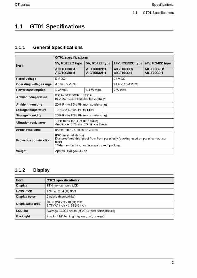
1.1.1 General Specifications
GT01 specifications
Item5V, RS232C type 5V, RS422 type 24V, RS232C type 24V, RS422 type
ItemAIGT0030B1/AIGT0030H1
AIGT0032B1/AIGT0032H1
AIGT0030B/AIGT0030H
AIGT0032B/AIGT0032H
Rated voltage 5 V DC 24 V DC
Operating voltage range 4.5 to 5.5 V DC 21.6 to 26.4 V DC
Power consumption 1 W max. 1.1 W max. 2 W max.
Ambient temperature 0°C to 50°C/32°F to 122°F(5 V DC max. if installed horizontally)
Ambient humidity 20% RH to 85% RH (non condensing)
Storage temperature -20°C to 60°C/-4°F to 140°F
Storage humidity 10% RH to 85% RH (non condensing)
Vibration resistance 10Hz to 55 Hz (1-minute cycle)Amplitude: 0.75 mm, 10 min on 3 axes
Shock resistance 98 m/s2 min., 4 times on 3 axes
Protective construction
IP65 (in initial status)Dustproof and drip-proof from front panel only (packing used on panel contact sur-face)* When reattaching, replace waterproof packing.
Weight Approx. 160 g/5.644 oz
1.1.2 Display
Item GT01 specificationsItem GT01 specifications
Display STN monochrome LCD
Resolution 128 (W) x 64 (H) dots
Display color 2 colors (black/white)
Displayable area 70.38 (W) x 35.18 (H) mm2.77 (W) inch x 1.39 (H) inch
LCD life Average 50,000 hours (at 25°C room temperature)
Backlight 3-color LED backlight (green, red, orange)

GT seriesSpecifications
4
1.1 GT01 Specifications
1.1.3 Functions
Item GT01 specifications
Displayable fonts
Fixed fonts: 1/4 width (8 x 8), half width (16 x 8), full width (16 x 16)Half width and full width characters can be displayed at same width, doubled width, orquadrupled widthTrue Type fonts and Windows fonts
Character types Alphanumeric characters
Graphics Straight lines, continuous straight lines, squares, circles, ovals, arcs, elliptic arcs, fanshapes, elliptic fan shapes, beveled squares, bitmaps
Number of screens
Screen numbers that can be set: Base screens No. 00 to FF (HEX)Number of screens that can be registered varies depending on registered contents.No. of parts that can be registered for one screen: 256 (Note: this includes the num-ber of message part replacements.)
Part functions Messages, lamps, switches, data, bar graphs, clocks, keyboard
Contrast adjustment Contrast can be adjusted using touch panel operation
Automaticcommunication settings
Settings for communication between dedicated software and PLC set automatically byconnecting cable
Debugging functions Through function (PLC can be debugged from personal computer by connecting com-puter to TOOL port and PLC to COM. port)
Screen creation Dedicated software Terminal GTWIN used.Applicable OS: Windows 95/98/2000/NT/XP
Password function Screen data transfer or capture cannot be executed without a password (screen dataprotection function).
* Clock functions are not available.
1.1.4 Touch Key
Item GT01 specifications
Touch key Analog touch key
Touch key operation 0.5 N max.
Touch key life Min. 106
* 1 The GT01 touch-switches operate using analog resistance membrane. Do not press two or more points on thescreen at the same time. Doing so might operate a switch located between those points if one exists.
* 2 This touch-panel is designed to be operated by touching. Please realize that the positional accuracy of the switchesis based on the size of a finger.
1.1.5 Memory (1)
Screen data and GTWIN Configuration Settings data
Item GT01 specificationsItem GT01 specifications
Memory type F-ROM
Memory capacity 384 kbytes

SpecificationsGT series
5
1.1 GT01 Specifications
1.1.6 Interface
GT01 specifications
ItemRS232C type RS422 type
ItemAIGT0030B1/ AIGT0030H1
AIGT0030B/ AIGT0030H
AIGT0032B1/ AIGT0032H1
AIGT0032B/ AIGT0032H
Communications ratings Conforms to RS232C (Non insula-tion type)
Conforms to RS422 (Non insulationtype)
Conditions forBaud rate: 9600, 19200, 38400, 57600, 115200 bits/s
Conditions forcommunications withexternal devices
Data bits: 7 or 8 bitsParity: None, Odd, EvenStop bits: 1 bit
COM.Port
Protocol Supports MEW FP Series/General-Purpose-Serial/Mitsubishi FX Series/Omron SYSMAC-C Series/ Modbus (RTU)o
Connector
Connector terminal base (8-pin)*Regarding power supply voltage, please pay due consideration to thecable length so that the applied voltage is within the operation voltagerange. Also, when supplying power from a power supply separate from thePLC, please make sure the power cable is no longer than 10 m.
Communications ratings Conforms to RS232C (Non insulation type)
TOOLport
Conditions forcommunications withexternal devices
Baud rate: 9600, 19200, 115200 bits/sData bits: 8 bitsParity: None, Odd, EvenStop bits: 1 bit
Protocol Dedicated protocol
Connector Mini-DIN (5-pin)
* 1 RS232C data transmission speed is 19,200 bit/s and the maximum cable length is 15 m.
* 2 Maximum cable length for RS422 data transmission is 30 m for the 5 V type and 500 m for the 24 V type.
* 3 When running a 5 V type directly with the PLC power supply, please comply with the PLC restrictions.For this reason, you may not be able to use at the distances given above. Please refer to Chapter 4 for details.

GT seriesSpecifications
6
1.2 GT01 Names and Functions of Parts
1.2 GT01 Names and Functions of Parts
1.2.1 GT01 (front)
(1) Liquid crystal display panel (touch panel)
1.2.2 GT01 (rear)
(2) COM. port and power supply terminal
(5) Waterproof packing
(3) TOOL port
(4) Operation mode setting switches
SpecificationsGT series
7
1.2 GT01 Names and Functions of Parts
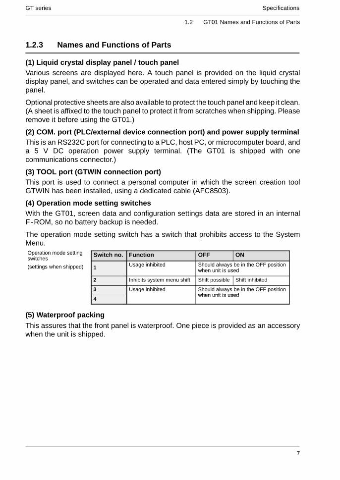
1.2.3 Names and Functions of Parts
(1) Liquid crystal display panel / touch panelVarious screens are displayed here. A touch panel is provided on the liquid crystaldisplay panel, and switches can be operated and data entered simply by touching thepanel.
Optional protective sheets are also available to protect the touch panel and keep it clean.(A sheet is affixed to the touch panel to protect it from scratches when shipping. Pleaseremove it before using the GT01.)
(2) COM. port (PLC/external device connection port) and power supply terminalThis is an RS232C port for connecting to a PLC, host PC, or microcomputer board, anda 5 V DC operation power supply terminal. (The GT01 is shipped with onecommunications connector.)
(3) TOOL port (GTWIN connection port)This port is used to connect a personal computer in which the screen creation toolGTWIN has been installed, using a dedicated cable (AFC8503).
(4) Operation mode setting switchesWith the GT01, screen data and configuration settings data are stored in an internalF-ROM, so no battery backup is needed.
The operation mode setting switch has a switch that prohibits access to the SystemMenu.
Switch no. Function OFF ON
1 Usage inhibited Should always be in the OFF positionwhen unit is used
2 Inhibits system menu shift Shift possible Shift inhibited
3 Usage inhibited Should always be in the OFF positionwhen unit is used
4when unit is used
(5) Waterproof packingThis assures that the front panel is waterproof. One piece is provided as an accessorywhen the unit is shipped.
Operation mode settingswitches
(settings when shipped)
GT seriesSpecifications
8
1.3 Internal Wiring Connections for Ports
1.3 Internal Wiring Connections for Ports
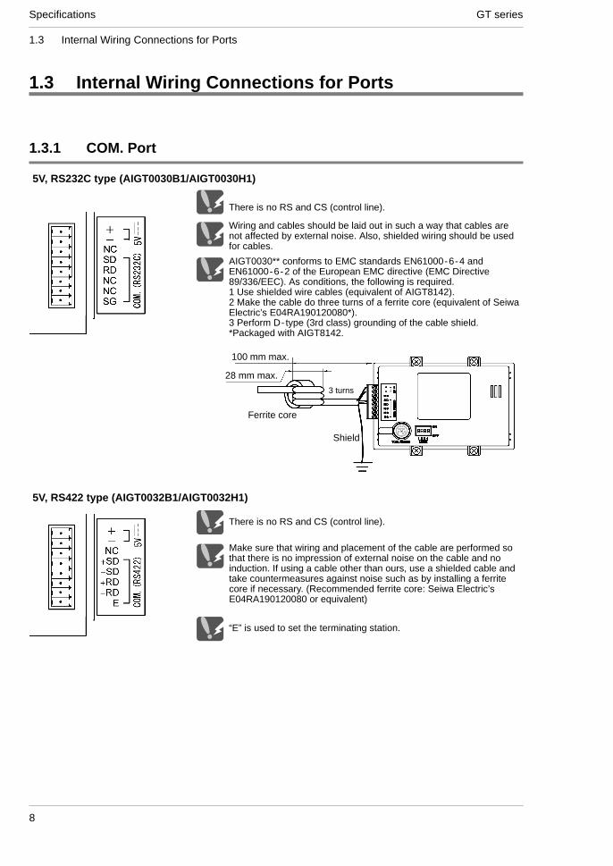
1.3.1 COM. Port
Wiring and cables should be laid out in such a way that cables arenot affected by external noise. Also, shielded wiring should be usedfor cables.
5V, RS232C type (AIGT0030B1/AIGT0030H1)
There is no RS and CS (control line).
AIGT0030** conforms to EMC standards EN61000-6-4 andEN61000-6-2 of the European EMC directive (EMC Directive89/336/EEC). As conditions, the following is required.1 Use shielded wire cables (equivalent of AIGT8142).2 Make the cable do three turns of a ferrite core (equivalent of SeiwaElectric’s E04RA190120080*).3 Perform D-type (3rd class) grounding of the cable shield.*Packaged with AIGT8142.
Make sure that wiring and placement of the cable are performed sothat there is no impression of external noise on the cable and noinduction. If using a cable other than ours, use a shielded cable andtake countermeasures against noise such as by installing a ferritecore if necessary. (Recommended ferrite core: Seiwa Electric’sE04RA190120080 or equivalent)
There is no RS and CS (control line).
“E” is used to set the terminating station.
5V, RS422 type (AIGT0032B1/AIGT0032H1)
100 mm max.
28 mm max.
3 turns
Ferrite core
Shield

SpecificationsGT series
9
1.3 Internal Wiring Connections for Ports
Wiring and cables should be laid out in such a way that cables arenot affected by external noise. Also, shielded wiring should be usedfor cables.
24V, RS232C type (AIGT0030B/AIGT0030H)
There is no RS and CS (control line).
AIGT0030** conforms to EMC standards EN61000-6-4 andEN61000-6-2 of the European EMC directive (EMC Directive89/336/EEC). As conditions, the following is required.1 Use shielded wire cables (equivalent of AIGT8162).2 Perform grounding of the cable shield.3 Perform grounding for the GT01.
Please verify the wiring details in the manuals for each connectiondevice.
Shield
Reference: “2.2.2 Grounding”
Be careful when wiring and laying cables to prevent external noisefrom being applied to the wiring cables and becoming inductive. Also,we recommend that you use shielded cables for the wiring.
Please verify with the manual regarding wiring details for each con-nected model.
To meet the European EMC Directive 89/336/EEC, the AIGT0032*complies with EMC standards EN61000-6-4 and EN61000-6-2. Asconditions, the following wiring is required.1 The use of shielded cables.2 Perform grounding of the cable shield3 Perform grounding of the GT01
There is no RS and CS (control line).
“E” is used to set the terminating station.
24V, RS422 type (AIGT0032B/AIGT0032H)
Reference: “2.2.2 Grounding”

GT seriesSpecifications
10
1.3 Internal Wiring Connections for Ports
1.3.2 TOOL Port
Pin No. Contents
1 SG
2 SD
3 RD
4 N.C.
5 N.C.

SpecificationsGT series
11
1.4 Dimensions
1.4 Dimensions
1.4.1 GT01 Dimensions
45 / 1.77
110 / 4.33
72/2
.83
4 /0.16
4 / 0.16
1 / 0.04
37.7
/1.4
8(D
ispl
ayun
it)
74.5 / 2.93 (Display unit)
2 / 0.08(Packing)
66/2
.60
24 / 0.94
104 / 4.09
9.5 / 0.37
Panel thickness5 mm 0.20 inch
Mounting panel
8 / 0.31
(Unit: mm/inch)

GT seriesSpecifications
12
1.4 Dimensions
1.4.2 GT01 Panel Cutout Dimensions
The panel cutout dimensions of the GT01 are as shown below.
Applicable panel thickness:1.0mm to 5.0mm
0.04inch to 0.20inch
105.0 0 / 4.13+0.04
/2.6
4+0.
0467
.0
+1
+1 0
*During installation when there will be other parts installed to the panel and wiringperformed, we recommend that you provide a 30 to 50 mm clearance around the GT01as a precaution against potential cable damage and to improve work efficiency whenperforming the installation.
Caution 1: Be absolutely sure not to seal the slits on the GT01.

Chapter 2
Installation and Wiring

GT seriesInstallation and Wiring
14

Installation and WiringGT series
15
2.1 Installation
2.1 Installation
2.1.1 Installation Environment
When installing and using the GT series, always make sure the following conditions areobserved.
Usage ConditionsWhen installing the product, make sure it is used within the range of the generalspecifications. Do not use in the following environments:
- Areas where the unit may come in contact with water (the unit is warranted byIP65 for the installed panel, but this applies to initial values and operation cannotbe guaranteed in areas where the unit is constantly subjected to water or toextreme temperatures or humidity).
- Areas where the ambient temperature exceeds the range 0°C to 50°C/32°F to122°F.
- Areas where the ambient humidity exceeds 20% RH to 85% RH.
- If the control panel and other parts are installed in an environment where the airtends to be poorly ventilated, forced cooling should be used to keep the ambienttemperature of the from going over 50°C/122°F. This prevents the temperature ofthe GT display unit from rising.
- Locations where condensation may form because of sudden fluctuations intemperature.
- Locations where flammable or corrosive gases are present.
- Locations where there are high concentrations of dust or iron filings.
- Locations where substances such as organic solvents (thinner, benzene, etc.) orstrong alkali substances (ammonia, caustic soda, etc.) might adhere to theproduct.
- Locations where the product is subject to extreme vibration and/or impact.
- Avoid installing the product near high-voltage lines, high-voltage devices, powerlines, power devices, amateur radio sets and other transmitters, and devices thatgenerate strong current surges.
- Avoid locations where the display unit is subject to direct sunlight.
Safety Precautions- The switch functions of the programmable display unit should not be used to
design systems which may pose a threat to human life or which may causesevere injury or damage. Designs should include safety mechanisms for use inthe event that switch functions do not function correctly.
GT seriesInstallation and Wiring
16
2.1 Installation
Power Supply Wiring- For the power supply, use twisted wire (strand wire).
- There is sufficient noise resistance to offset power line noise, but we recommendreducing noise by measures such as installing an insulated transformer.
- Separate wiring systems should be used for the power supply unit and theoperating unit.
Static Electricity/Noise- Keep the GT01 main unit, PLC connecting cable, and other wiring as far away as
possible from machines which are likely to produce noise (welding equipment,power lines, inverters, motors, etc.).
- For use in environments where the frequent occurrence of static electricity,radiation, or induced noise can be expected, the use of shielded cable on allwiring and grounding of shield (1-point ground) is recommended. When wiringthe equipment, shielded wires should be electrically insulated to signal lines andsignal grounds.
- If excessive static electricity is applied to the panel surface, the LCD display unitmay be damaged.
Other Precautions- Do not leave the GT connected to the TOOL port of the FP Programmer II.
- Always operate the touch panel with your fingers. Excessive load (about 98N/cm2 ) or impact (operating with tools, etc.) will cause damage. Touch paneloperation must be within the standard operating power range. Uniform pressureshould be used to avoid abnormal wear of electrodes which may disableoperation. Operate the unit only by touch.
- Never dismantle, re-assemble, or alter the unit. Performance cannot bewarranted if this precaution is disregarded.

Installation and WiringGT series
17
2.1 Installation
2.1.2 GT01 Installation Method
Secure the GT01 to the installation panel using the four fittings and four screwsprovided with the unit.
(1) Place the GT01 main unit in the installation panel.(2) Insert the fittings into the grooves provided in the GT01 main unit, and tightenthe screws to secure the GT01 main unit to the installation panel.
Enlarged view
CAUTION
Screw tightening torqueThe screw tightening torque should be 0.1 N m to 0.25 N m.Applicable panel thicknessA panel with a thickness of 1.0 mm to 5.0 mm should be used.Clearance when the GT01 is installedWhen installing the GT01, if other parts are being installed to thepanel or cables are being wired to it, we recommend providing aclearance of 30 mm to 50 mm/1.18 inch to 1.97 inch around the GT01.This prevents cables from being damaged, and facilitates theinstallation work. Also, make sure that the slits in the main unit arenever obstructed.

GT seriesInstallation and Wiring
18
2.2 Wiring the Power Supply
2.2 Wiring the Power Supply
2.2.1 Wiring the Power Supply
The power supply should be wired by securely connecting the terminal on the rear ofthe main unit to the terminal.
Use twisted wiring for the power supplyIn order to minimize influence from noise, the wiring for the power supply should betwisted.
Insulate the power supply inside a protective circuit- In order to protect the unit against abnormal voltage from the power supply line, thepower supply should be an insulated type, and should be enclosed within a protectivecircuit.- A non- insulated regulator is used with the GT series.- If a power supply device without an internal protective circuit is being used, powershould always be supplied to the GT series through a fuse or a similar protective device.
Keep the power supply voltage within the operating voltage rangePart No. Operating voltage range
AIGT0030B1/AIGT0030H1
AIGT0032B1/AIGT0032H1
4.5V DC to 5.5V DC
AIGT0030B/AIGT0030H
AIGT0032B/AIGT0032H
21.6V DC to 26.4V DC
Keep the power supply wiring separate- Wiring to the GT series, PLC, and other power equipment should have separate wiringsystems.
PLC
GT series
Breaker
Powerequipment
Insulated DCpower supply

Installation and WiringGT series
19
2.2 Wiring the Power Supply
2.2.2 Grounding
Be sure to ground when the influence of noise is greatThe unit is tolerant against noise in normal environments, but if the environment isparticularly susceptible to noise, please ground.
Use dedicated grounding-For grounding purposes, use wires with a minimum of 2 mm2. The groundingconnection should have a resistance of less than 100 Ω.
-Make the grounding point as close as possible to the GT01 and keep the distance ofthe grounding wire short.
-Sharing the ground with another device may have an adverse effect. Therefore, besure that grounding is dedicated.
Allowed
GT GTOther devicesuch as inverter
Other devicesuch as inverter
Not allowed
CAUTION
Conversely, depending on your environment, grounding may cause aproblem.Example:Since the power line of the GT unit is connected to a functional earthvia electronic parts, the electronic parts may become damaged ifthere is an abnormal potential between the power line and thephysical ground.
24 V DC
0 V
GT01 power line
Functionalearth

GT seriesInstallation and Wiring
20
2.3 Wiring the COM. Port
2.3 Wiring the COM. Port
2.3.1 Wiring the COM. Port
Accessory communication connector/applicable wiringThe communication connector used for the COM. port (provided as an accessory withthe main unit) has a screw- tightening type of terminal base. The wiring shown belowshould be used.
Applicable wiring (twisted wiring)Size Conductor Cross-Section Surface Area
AGW#28 to 16 0.08 mm2 to 1.25 mm2
Use a special tool to tighten the terminal base of the communication connectorUsing a screwdriver made by Matsushita Electric Works Co., Ltd. (Product numberAFP0806). The tightening torque should be 0.22 N·m to 0.25 N·m or less.
2.3.2 Wiring Method
(1) Remove the sheath from the wire.
7 mm/0.28 inch
(2) Insert the wire all the way into the terminal base, and tighten the screw in theclockwise direction to secure it.

Installation and WiringGT series
21
2.3 Wiring the COM. Port
2.3.3 Precautions Concerning Wiring
The following precautions should be observed, to avoid broken or disconnected wires.
- When removing the sheath, be careful not to scratch the core wire.
- Wire the terminal without twisting the core wire.
- The core wire should be connected without soldering it. Vibration can sometimescause soldered connections to break loose.
- After connecting the wiring, avoid subjecting the cable to stress.
- Because of the construction of the terminal, tightening the wire in thecounterclockwise direction will cause a faulty connection. If this happens,disconnect the wire, check the terminal hole, and connect the wire again.
CounterclockwiseClockwise
REFERENCE
For information on connecting the COM. port of the GT series withvarious PLC units, please see Chapter 4, “Connecting andCommunicating with the PLC”, on page 31.

GT seriesInstallation and Wiring
22
2.3 Wiring the COM. Port

Chapter 3
Setup

GT seriesSetup
24

SetupGT series
25
3.1 Setup Procedure for the GT01
3.1 Setup Procedure for the GT01
3.1.1 Setup Procedure
The GT01 should be set up using the procedure outlined below.
(1) Setting the “Configuration File” with GTWINThe GT01 has an internal file called the “Configuration file”, which is used to determinevarious operating environment parameters. When the GT01 is shipped from the factory,the settings listed below are set for the parameters in the configuration settings file. Ifchanges are made to these settings, they are made from GTWIN screen creation tool.If the GT01 is being used without changing the factory settings, the following setupprocedure is not necessary.
Contents of configuration settings for GT01 when shipped from the factoryClassification Item Setting contents
Basic SetupArea for basiccommunicationwith PLC
Mode : GT01 modeWord area: DT0 to DT2Bit area : WR0 to WR2
Communicationparameter
COM. portCommunication speed: 19200 bits/s, data length: 8 bits, stop bit: 1 bit, parity: odd<Communication error temporary processing> Retries: 3, error code displayed(not held)parameter
settingsTOOL port Communication speed: 19200 bits/s, data length: 8 bits, stop bit: 1 bit, parity: odd
<Through function local setting> None
Auto paging Automatic paging No
Startup screen Startup screen No. 00Startup screensettings Rise delay time 0 seconds
Backlight control Not turned off automatically
Other settings Touch operationsounds
Valid
Always confirm “Basic communication area to PLC” under “Basic Setup”This is an internal device area that comes already provided in the GT01 for the purposeof communicating with a PLC. If the factory settings are to be changed, the setupprocedure must be carried out. For detailed information, please see page 28.
(2) Connect the GT01 and the personal computer.After the settings have been entered with GTWIN, connect the computer and the GT01,using the screen transfer cable.
Screen transfercable (AFC8503)

GT seriesSetup
26
3.1 Setup Procedure for the GT01
(3) Transfer the GT01 Configuration file from GTWIN.After connections have been completed, use the following procedure to transfer theGT01 Configuration file from GTWIN.
Boot GTWIN, and select “Transfer” on the “File” menu.
When the transfer function is selected, a dialog box for file transfer is displayed.At this point, specify the type of data to be transferred, and the direction oftransfer.Transfer data: “GT01 Configuration”Transfer direction: “GTWIN → GT main unit”Enter the above conditions and click on the “OK” button. The system files aretransferred to the GT01.

SetupGT series
27
3.1 Setup Procedure for the GT01
When the menu operation as shown at the left page is carried out, the configuration fileis sent to the GT01. During the transfer, a screen like that shown below is displayed.
Screen transfer cable(AFC8503)
GT01 Configurationfile being transferred
(4) Setup is completed.If the transfer has been completed without any problems, the setup is completed.
CAUTION
Backup of the GT01 Configuration fileThe GT01 Configuration file is stored in the user memory (F-ROM) of theGT01. This file is deleted if the memory is initialized using the commandon the system menu of the GT01 main unit (see page 90), and will haveto be transferred again.

GT seriesSetup
28
3.2 Setting the Basic Communication Area Between the GT01 and PLC
3.2 Setting the Basic Communication Area Between theGT01 and PLC
3.2.1 What is the Basic Communication Area?
Communication between the GT01 and PLC is carried out as shown below.
PLCInternal PLC devices
Part reference / output deviceFor part functions
(free device specification)
Basic communication areaFor screen switching settings and systemcontrol(word device / bit device: 3 words each)Ongoing
Communication
As shown in the illustration, communication is carried out on an ongoing basis betweenthe GT01 and internal devices in the PLC. Internal PLC devices are divided into thefollowing two devices:Basic communication areaThis area is for system control, such as screen switching settings. PLC devices belongto this area on a fixed basis, and communication is constantly being carried out.
Breakdown of the basic communication area
Word devices (DT, FL, etc.)
3 consecutive words
Bit devices (WR, etc.)
3 consecutive words
- Word devices - - - For reading devices handled in word units (3 consecutive words)
- Bit devices - - - For reading devices handled in bit units (3 consecutive words)
References and output devices for partsThese are devices that are used in parts functions, and can be freely specified by theuser. Communication is carried out on an ongoing basis only for those that are currentlydisplayed on the screen and pertain to devices currently in use.
With the GT01, before GTWIN screen creation tool is used to specify the devices forparts functions, the “basic communication area” must be determined.DT0 to DT2 and WR0 to WR2 are set as the default values for the basic communicationarea, but the initial address can be changed using the following procedure.
CAUTION
The basic communication area should be used in the PLC ladderprogram to control the GT main unit.

SetupGT series
29
3.2 Setting the Basic Communication Area Between the GT01 and PLC
Settings in GTWINSelect “Configuration” under “File” on the menu bar, and then select the sub-menucalled “GTWIN Configuration”. This displays the dialog box for the GT01 Basic Setup,as shown below.Clicking on the button in “Basic Communication Area to PLC” displays the devicesettings dialog box shown below, where the initial addresses for the word area and bitarea can be changed.
GT01 Configuration Basic Setup dialog box
Explanation of this function
Key operation in the Device Settings dialog boxClick on the button to display a pull -down menu, and then select
the device for which settings are to be entered. Use the ten-keys toenter the address.The button acts as a backspace key when entering an address,
and the button functions as a Clear key.

GT seriesSetup
30
3.2 Setting the Basic Communication Area Between the GT01 and PLC
3.2.2 GT01 Basic Communication Area Map
In order for communication to be carried out between the GT01 and PLC, an internaldevice area like that shown below is provided in the PLC. This should be used to controlthe GT main unit through the PLC ladder program actually being run.The starting address “N” of the field shown below is specified in the GT01 configurationsettings of GTWIN screen creation tool, and is then sent to the GT main unit.
Word devicesWord position F E D C B A 9 8 7 6 5 4 3 2 1 0
N+0 Screen no. specified by PLC (area read by GT01 from PLC)
N+1 Usage prohibited
N+2 No. of currently displayed screen (area in which data is written from GT01 to PLC)
Explanation of system area
Screen no. specified by PLC - - - The screen number displayed on the GT01 isspecified from the PLC in hexadecimal format.
No. of currently displayed screen - - - The number of the screen currentlydisplayed on the GT01 is written to the PLC in hexadecimal format.
Bit devicesWordposition F E D C B A 9 8 7 6 5 4 3 2 1 0
N+0 BZ Forced-display flag
BacklightValid flag
BacklightFlashing
BacklightColor
N+1 Usage prohibited
N+2 Data Input InProgress flag
Explanation of system areas
BZ - - - This turns on the buzzer.
Forced-Display flag - - - At the rise when the bit is turned on, the screen specified bythe PLC is forcibly displayed. (This is executed only when at the rise of the bit.)
Backlight Valid flag - - - When the bit is turned on, the backlight flashing/backlightcolor control becomes effective.
Backlight Flashing - - - 0: Lighted (normal), 1: Flashing
Backlight Color - - - 00: Off, 01: Green, 10: Red, 11: Orange
Data Input In Progress flag - - - This is 1 while data is being input, and 0 when datainput has been completed.

Chapter 4
Connecting and Communicating with thePLC

GT seriesConnecting and Communicating with the PLC
32
Connecting and Communicating with the PLCGT series
33
4.1 Connecting the FPΣ
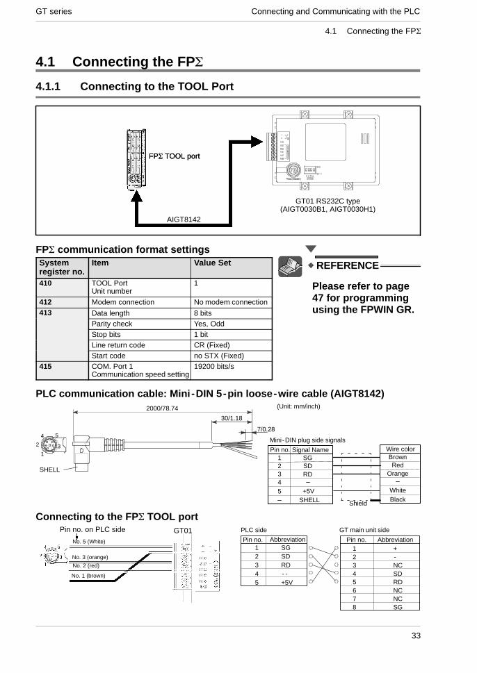
4.1 Connecting the FPΣ
4.1.1 Connecting to the TOOL Port
FPΣ TOOL port
GT01 RS232C type(AIGT0030B1, AIGT0030H1)
FPΣ communication format settingsSystemregister no.
Item Value Set
410 TOOL PortUnit number
1
412 Modem connection No modem connection413 Data length 8 bits
Parity check Yes, OddStop bits 1 bitLine return code CR (Fixed)Start code no STX (Fixed)
415 COM. Port 1Communication speed setting
19200 bits/s
PLC communication cable: Mini -DIN 5-pin loose-wire cable (AIGT8142)
3
54
1
2Mini-DIN plug side signals
Signal Name1 SG
SDRD
2345
Wire colorBrownRed
Orange
+5V WhiteBlackSHELL Shield
SHELL
7/0.28
30/1.18
2000/78.74 (Unit: mm/inch)
Pin no.
Connecting to the FPΣ TOOL portGT01
No. 1 (brown)
Pin no. on PLC side
No. 3 (orange)
No. 2 (red)
PLC side
Pin no. Abbreviation1 SG2 SD3 RD4 - -5 +5V
Abbreviation
GT main unit side
Pin no.1 +2 -3 NC4 SD5 RD6 NC7 NC8 SG
No. 5 (White)
AIGT8142
FPΣ TOOL port
REFERENCE
Please refer to page47 for programmingusing the FPWIN GR.

GT seriesConnecting and Communicating with the PLC
34
4.1 Connecting the FPΣ
CAUTION
Please keep the cable no longer than 3 m.In case of connecting to PLC with all expansion slots used, pleaseprepare an external 5V DC power supply for the GT01 due to currentconsumption limits.

Connecting and Communicating with the PLCGT series
35
4.2 Connecting the FP0
4.2 Connecting the FP0
4.2.1 Connecting to the TOOL Port
AIGT8142
FP0 TOOL port
GT01 RS232C type(AIGT0030B1, AIGT0030H1)
FP0 communication format settingsSystemregister no.
Item Value Set Systemregister value
410 Unit number 1 K1
411 Data length 8 bits H0
Modemconnection No connection
414 Baud rate setting 19200 bits/s H010XX is 0 to 6
PLC communication cable: Mini -DIN 5-pin loose-wire cable (AIGT8142)
3
54
1
2Mini-DIN plug side signals
Signal Name1 SG
SDRD
2345
Wire colorBrownRed
Orange
+5V WhiteBlackSHELL Shield
SHELL
7/0.28
30/1.18
2000/78.74 (Unit: mm/inch)
Pin no.
Connecting to the FP0 TOOL portGT01
No. 1 (brown)
Pin no. on PLC side
No. 3 (orange)
No. 2 (red)
PLC side
Pin no. Abbreviation1 SG2 SD3 RD4 - -5 +5V
Abbreviation
GT main unit side
Pin no.1 +2 -3 NC4 SD5 RD6 NC7 NC8 SG
No. 5 (White)
REFERENCE
Please refer to page47 for programmingusing the FPWIN GR.
←To set 19200 bits/s for both the COM.port and the TOOL port, “H0100” shouldbe set.

GT seriesConnecting and Communicating with the PLC
36
4.2 Connecting the FP0
CAUTION
Please keep the cable no longer than 3 m.In case of connecting to PLC with all expansion slots used, pleaseprepare an external 5V DC power supply for the GT01 due to currentconsumption limits.

Connecting and Communicating with the PLCGT series
37
4.3 Connecting the FP2/FP2SH
4.3 Connecting the FP2/FP2SH
4.3.1 Connecting to the TOOL Port
AIGT8142
FP2/FP2SH CPU TOOL port
GT01 RS232C type(AIGT0030B1, AIGT0030H1)
FP2/FP2SH communication format settingsSystem register no. Item Value Set
410 Unit number 1
411Data length 8 bits
411Modem connection No connection
414 Baud rate setting 19200 bits/s
PLC communication cable: Mini -DIN 5-pin loose-wire cable (AIGT8142)
3
54
1
2Mini-DIN plug side signals
Signal Name1 SG
SDRD
2345
Wire colorBrownRed
Orange
+5V WhiteBlackSHELL Shield
SHELL
7/0.28
30/1.18
2000/78.74 (Unit: mm/inch)
Pin no.
Connecting to the FP2/FP2SH TOOL portGT01
No. 1 (brown)
Pin no. on PLC side
No. 3 (orange)
No. 2 (red)
PLC side
Pin no. Abbreviation1 SG2 SD3 RD4 - -5 +5V
Abbreviation
GT main unit side
Pin no.1 +2 -3 NC4 SD5 RD6 NC7 NC8 SG
No. 5 (White)
REFERENCE
Please refer to page47 for programmingusing the FPWIN GR.

GT seriesConnecting and Communicating with the PLC
38
4.3 Connecting the FP2/FP2SH
CAUTION
Please keep the cable no longer than 3 m.When supplying power from the TOOL port, please verify whether ornot it will be possible by using the method of calculation for thenumber of expansion units that is provided in the hardware manual.

Connecting and Communicating with the PLCGT series
39
4.4 Connecting the FP10SH
4.4 Connecting the FP10SH
4.4.1 Connecting to the TOOL Port
FP10SH CPU TOOL Port
SW No.
0 119200bit/s
8bit
OFFOFF ON
1 2 3 4 5 6 7 8DIP SW 1
DIP SW 2
DIP SW 2
FP10SH communication format settings
GT01 RS232C type(AIGT0030B1, AIGT0030H1)
No relation to GT01 communication.
Unit No.Setting
No relation to GT01communication.
Set port Tool port Memory COM. setting port
Settingcapacity
Trans-ferspeed
Datalength
Modemcontrol
Programmemoryprotect
Programmemoryselection
Transfer speed
Setting NoneNo relation to GT01communication.
Switchstatus
The cable madepersonally
Connecting to the FP10SH TOOL portPlease create a cable from the following contents.
Pin no. on PLC side
PLC side
Pin no. Abbreviation Abbreviation
GT main unit side
Pin no.
Please short the wiring.
CAUTION
Please keep the cable no longer than 3 m.When supplying power from the TOOL port, please verify whether ornot it will be possible by using the method of calculation for thenumber of expansion units that is provided in the hardware manual.
GT seriesConnecting and Communicating with the PLC
40
4.5 Connecting the FP-M
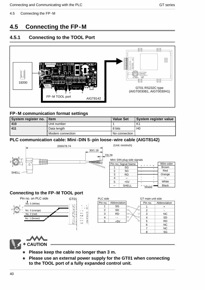
4.5 Connecting the FP-M
4.5.1 Connecting to the TOOL Port
19200
AIGT8142FP-M TOOL port
GT01 RS232C type(AIGT0030B1, AIGT0030H1)
FP-M communication format settingsSystem register no. Item Value Set System register value410 Unit number 1 K1411 Data length 8 bits H0
Modem connection No connection
PLC communication cable: Mini -DIN 5-pin loose-wire cable (AIGT8142)
3
54
1
2Mini-DIN plug side signals
Signal Name1 SG
SDRD
2345
Wire colorBrownRed
Orange
+5V WhiteBlackSHELL Shield
SHELL
7/0.28
30/1.18
2000/78.74 (Unit: mm/inch)
Pin no.
Connecting to the FP-M TOOL portGT01
No. 1 (brown)
Pin no. on PLC side
No. 3 (orange)
No. 2 (red)
PLC side
Pin no. Abbreviation1 SG2 SD3 RD4 - -5 +5V
Abbreviation
GT main unit side
Pin no.1 +2 -3 NC4 SD5 RD6 NC7 NC8 SG
No. 5 (White)
CAUTION
Please keep the cable no longer than 3 m.Please use an external power supply for the GT01 when connectingto the TOOL port of a fully expanded control unit.

Connecting and Communicating with the PLCGT series
41
4.6 Connecting the GT01 (24V DC type) and FP Series (1)
4.6 Connecting the GT01 (24V DC type) and FP Series (1)
4.6.1 Connecting to the TOOL Port of FP Series
AIGT8162
FPΣ TOOL port
FP0FP2/FP2SH
PROG.
RUN
COM.1SR
COM.2SR
X0-7
Y0-7
X8-F
Y8-F
RUN
PROG.
ALARM
ERROR
FP0H
-C32
T
X
Y
0
2
4
6
1
3
5
7
8A
C
E
9
BD
F02
4
6
1
3
5
7
8
AC
E
9
BD
F
V1
V0
min.
max.
24V power supply
GT01 RS232 type(AIGT0030B, AIGT0030H)
FPΣ communication format settingsSystemregister no.
Item Value Set
410 TOOL PortUnit number
1
412 Modem connection No modem connection413 Data length 8 bits
Parity check Yes, OddStop bits 1 bitLine return code CR (Fixed)Start code no STX (Fixed)
415 COM. Port 1Communication speed setting
19200 bits/s
PLC communication cable: Mini -DIN 5-pin loose-wire cable (AIGT8162)
3
54
1
2Mini-DIN plug side signals
Signal Name1 SG
SDRD
2345
Wire colorBrownRed
Orange
BlackSHELL Shield
SHELL
7/0.28
30/1.18
2000/78.74 (Unit: mm/inch)
Pin no.
REFERENCE
Please refer to page47 for programmingusing the FPWIN GR.

GT seriesConnecting and Communicating with the PLC
42
4.6 Connecting the GT01 (24V DC type) and FP Series (1)
Connecting to the FPΣ TOOL port
PLC side
Pin No. Abbreviation
SD
+-
GT main unit side
RD
Pin No. Abbreviation1 SG
SDRD
2345
PLC side pin No. GT01
No.2 (Red)
No.1 (Brown)
3
54
1
2
--
NCNC
FG
SG
12345678
No.3 (Orange)
24Vpower supplyTo 24V
power supply
SDRDNCNCSG
-+
CO
M.(
RS
232C
)24
V

Connecting and Communicating with the PLCGT series
43
4.7 Connecting the GT01 (24V DC type) and FP Series (2)
4.7 Connecting the GT01 (24V DC type) and FP Series (2)
4.7.1 Connecting to the COM Port of FP Series
Connecting to the FPΣ COM port
24Vpower supply
FPΣ
PLC side
Pin No. Abbreviation
SD SDFG FG- -+ +
RD
NC
GT main unit side
SG
NCRDNCNCSG
RS232C
FPG-COM1
SGCSRSRDSD
AFPG801
Pin No. AbbreviationSD SD
RD
CSSG
RSRDRSCSSG
When using the RS232C 1-channel type
When using the RS232C 2-channel type
To 24Vpower supply
GT main unit side
PLC side
Pin No. Abbreviation
SD SDFG FG- -+ +
RD
NCSG
NCRDNCNCSG
Pin No. AbbreviationSD SD
RD
RDSG
SDRDRSCSSG
To 24Vpower supply
SDRDNCNCSG C
OM
.(R
S23
2C)
24V
+-
When using the RS232C 1 - channel type, thesection between the RS and CS signals on thePLC side should be shorted.
Connecting to the FP0 COM port
24VTo power supply
FP0
PLC side
Pin No. Abbreviation+ +
-
SD
GT main unit side
RD
FG-
FGSDRD
NCNCNCNCSGSG
Pin No. AbbreviationS SD
RDSG
RG
24Vpower supply
SDRDNCNCSG C
OM
.(R
S23
2C)
24V
+-
CAUTION
We do not provide a dedicated cable for hard wiring to the FP0 COMport. Please provide your own cable. If you provide a cable for thispurpose, please note the following.Please use AWG #28 to 16 size shielded cable (with a conductorcross sectional area of 0.98 mm2 to 1.25 mm2).Please refer to page 47 for programming using the FPWIN GR.

GT seriesConnecting and Communicating with the PLC
44
4.7 Connecting the GT01 (24V DC type) and FP Series (2)
4.7.2 Connecting to the COM Port of Other Units (FP1, FP2, FP2SHand CCU unit)
PLC communication cable: D-SUB 9-pin loose-wire cable (AIGT81842)
12345
6789
L 50/1.95
10/0.39 (shielded mesh wire section)
(Unit: mm/inch)
Pin No. Wire color Dot mark1 Brown Black
BrownYellow
Red
Red
Red
Specifications
D-SUB side signals
Product No.
AIP81842
L
2m/6.56 ft.D-SUB 9-pinSingle-sideloose wire
Black
BlackYellowGreen
Green
23456789
Connecting to the COM port
12345
6789
No.3 (yellow: black dot mark)
PLC side pin No.
No.2 (brown: red dot mark)
No.7 (green: red dot mark)
No.4 (yellow: red dot mark)
Short wiring here
No.5 (green: black dot mark) PLC side GT main unit side
Pin No. Abbreviation
SD SDFG FG- -+ +
RD
NCSG
NCRDNCNCSG
Pin No. Abbreviation
4 RS3 RD2 SD1 FG
CS
SGN.C.
N.C.5678
ER9
24Vpower supply
SDRDNCNCSG
-+
CO
M.(
RS
232C
)24
V
To 24Vpowersupply

Connecting and Communicating with the PLCGT series
45
4.8 Connecting the FPΣ Communication Cassette
4.8 Connecting the FPΣ Communication Cassette
4.8.1 Connecting to the FPΣ Communication Cassette COM. (AFPG803)
FPΣ COM3
GT01 RS422 type(AIGT0032B*, AIGT0032H*)
FPΣ communication format settingsItem Value SetCOM. port 1 unit number No. 1COM. port 1 communication mode Computer link
COM. port 1 transfer format 8 bits, odd, 1 stop, terminal CR(fixed), and no STX
COM. port 1 transmission speedsetting
38,400 bit/s, 57,600 bit/s, 115,200bit/s
*Please use a communication speed of 38,400 bit/s or higher.
Pin No.
+SD
+5V (+24V)GNDNC
-SD+RD-RD
NCSignal Name
+
E
-
-+-E
+ +SD-SD+RD-RD
Abbreviation
FPΣ side (AFPG803)
(Terminal station setting/120 Ω resistor built in)
Short circuit(Terminal station setting/120 Ω resistor built in)
To power supply GT01 side
CAUTION
Use with 1:1.If noise is a problem, use a shielded cable and employcountermeasures such as installing a ferrite core if necessary.The transfer distance is 30 m maximum. (Up to 500 m is possible withthe 24 V type.)You cannot use any port other than COM3 when communicating withan FPΣ using RS485.
REFERENCE
Please refer to page47 for programmingusing the FPWIN GR.

GT seriesConnecting and Communicating with the PLC
46
4.7 Cautions Regarding Direct Connection of GT01 (5V DC type) to the FP Series TOOL Port
4.9 Cautions Regarding Direct Connection of GT01 (5VDC type) to the FP Series TOOL Port
When directly connecting a GT01 to an FP Series TOOL port, a limit will apply to thenumber of units that can be expanded due to the capacity of the FP Series powersupply. Please proceed in accordance with the information given below.
FP Series Type Limitations when Connecting a GT01FP0 Maximum of two expansion units *1
FPΣ Maximum of six expansion units *1
FP2 The method for calculating the number of units that can be expanded is provided in thecontrol unit hardware manual Follow that formula and keep the GT01’s 5V power consump
FP2SHcontrol unit hardware manual. Follow that formula and keep the GT01’s 5V power consump-tion no higher than 200 mA when calculating.
FP10SHtion no higher than 200 mA when calculating.
FP-M Maximum of three expansion units *1
FP-e There are no particular restrictions.
*1 Expansion is possible with the number of units given above, regardless of the type of unit.*Please perform connections with the power turned off.

Connecting and Communicating with the PLCGT series
47
4.10How to Make Communication Settings Using the FPWIN GR
4.10 How to Make Communication Settings Using theFPWIN GR
Please read below to make PLC communication settings using the FPWIN GR.
1. Select “PLC system register setting” from the Option menu (O).
2. The window below will be displayed.Select “Tool port setting” when connecting to the Tool Port or “COM port setting” whenconnecting to the COM port. Please match the transfer format and transmissionspeed settings to those of the GT.
In addition to the transfer format and transmission speed settings, set thecommunication mode to “Computer link” when using the COM port.
Select “Computer link”

GT seriesConnecting and Communicating with the PLC
48
4.11 Automatic Communication Settings Function
4.11 Automatic Communication Settings Function
After turning on the power supply, if there is no response from the PLC connected tothe GT01, the GT01 switches to the automatic setting mode for the communicationconditions. In the automatic setting mode, commands are sent to the PLC whilechanging the communication conditions in the sequence shown below.
GT01
PLC
(1) 9600 bits/s, 8 bits, odd parity, 1 stop bit(2) 19200 bits/s, 8 bits, odd parity, 1 stop bit(3) 115200 bits/s, 8 bits, odd parity, 1 stop bit(4) Communication conditions set in GTWIN Configuration Settings
If there is no response from the PLC,commands are sent to the PLC whilechanging the communication conditions.
The GT01, in automatic setting mode, continues to repeat steps (1) to (4) until there isa response from the PLC. While it is repeating these steps, it is in the “Standby” modeunder “GT01 Configuration” a “Communication Parameters” a “Handle CommunicationError” on GTWIN. For information on how settings are entered, please refer to page 77.
Explanation of this function
Conditions when the automatic settings mode is in effectIf communication is attempted the specified number of times andthere is no response from the PLC, the GT01 goes into the automaticsettings mode. The number of attempts is specified using the “No. ofRetries” parameter under “GT01 Configuration” → “CommunicationParameters” → “Handle Communication Error” on GTWIN. Forinformation on how settings are entered, please refer to page 77.Automatically set communication conditionsIn the automatic settings mode, if there is a response from the PLC,subsequent communication is carried out under conditions matchingthe response. The main unit configuration settings are not updated,however, even if the communication parameters are different fromthose of the main unit configuration settings.

Connecting and Communicating with the PLCGT series
49
4.11 Automatic Communication Settings Function
CAUTION
An error response from the PLC is taken as a response, and the GT01does not go into the automatic settings mode.If the unit is connected to the COM port of theFP0/FP1/FP2/FP2SH/FP-M, communication between the FP deviceand the PLC will not be possible if the target usage of the RS232Cport has been set to “Computer Link”. Always set the setting on thePLC side to match “Computer Link”. For detailed information, pleaserefer to Chapter 4, “Connecting and Communicating with the PLC”,on page 31.

GT seriesConnecting and Communicating with the PLC
50
4.12 Through Function
4.12 Through Function
With the GT series, communication can be set to take place automatically between theCOM. and TOOL ports in a “through function”. When the FP series tool softwareinstalled in the computer connected to the GT series as shown below is booted, PLCprograms can be edited through the GT series.
The through function does not require any special settings, and is always in the standbymode.
PLC
GT01Connected by cableto the TOOL port ofthe PLC
ScreentransfercableAFC8503
Screen databeing sentand received
Screen creation tool GTWINFP series programming tool FPWIN GR
Personal computer
The FPWIN GR can booted on the com-puter being used to edit the GT seriesscreens, and the PLC programs can beedited and monitored through the GTseries.
PLC debugging

Connecting and Communicating with the PLCGT series
51
4.12 Through Function
CAUTION
Precautions when using the through functionThe system should be set up so that the interval for communicationretries in the FP series software (FPWIN GR or NPST-GR) (A) is largerthan that of the GT01 COM. port (B), meaning (A) > (B). If the systemis set up so that A = B or A < B, the through function will not workproperly.Restrictions on COM. port connectionsWhen connecting the GT01 to the COM port of a PLC, a separateexternal DC 5 V power supply must be provided. Be sure toremember this.An FP Programmer II cannot be connected to the tool port.
FP Programmer II

GT seriesConnecting and Communicating with the PLC
52
4.13 Connecting a Mitsubishi Electric PLC
4.13 Connecting a Mitsubishi Electric PLC
4.13.1 FX Series Direct Tool Port Connection (RS422)
AIGT8152
GT01 RS422 type(AIGT0032B1, AIGT0032H1)
Mitsubishi Electric PLCFX Series
PLC communication cable: Mini -DIN 8-pin loose-wire cable (AIGT8152)
Specifications Product No.
AIGT8152
L
2mMini -DIN 8-pin
Single-side6 loose wires
(Unit: mm) Mini -DIN plug side signals
3
54
12
8
67
2000
50
7
Pin No. Abbreviation
1 -RD
+RD
SG
2
3
4
5 +5V
+SD
SHELL
6
7
8
-SD
Wire color
Green
Yellow
Brown
White
Orange
Red
Tool port connection of GT01 and FX SeriesPLC
+SD
+5VGND
GT01
NC
-SD+RD-RD
NC
Pin No. Pin No.Abbreviation Abbreviation1 -RD
+RDSG
234
5 +5V
+
E
-
67
8
-SD
+SD
+SD-SD+RD-RD
Terminal station settingShort -RD and E.
(120 Ω resistor built in)
CAUTION
Please keep the cable no longer than 2 m.GT01 power consumption corresponds to that of Mitsubishi’s F920 (5V type) display device. When using, please adhere to the conditionsof use (number of units that can be expanded on a PLC, etc.) for theF920 (5 V type).

Connecting and Communicating with the PLCGT series
53
4.13 Connecting a Mitsubishi Electric PLC
Setting the Communication Conditions-Setting communication conditions on the GT sideSet the COM. Port communication conditions as follows.
Item Value Set
Communication speed setting 9600 bit/s
Data length 7 bits
Parity check Yes, even
Stop bit 1 bit
-Setting communication conditions on the PLC sideStore ”0” in D8120. (Since the default is ”0”, there is no need to set this.)
Usable devicesDevice Type Comment
Bit device Input relay (X)
Output relay (Y)
Internal relay (M)
State (S)
Timer (contact) (TS)
Counter (contact) (CS)
Word device Input relay (X) Designate the address in increments of 20.
Output relay (Y) Designate the address in increments of 20.
Internal relay (M) Designate the address in multiples of 16.
State (S) Designate the address in multiples of 16.
Timer (contact) (TN)
Counter (contact) (CN)
Data register (D)
Note 1: The addresses you can use may differ depending on the model. For details, please see the manual for the PLCyou are using.
Note 2: If using an input relay, output relay and auxiliary relay in word units, please set the address in 16 pointincrements from 000. (X000, X020, X040..., M000, M016, M032)
REFERENCE
For details on error codes please see “8.2 Error Codes and How toHandle Them”.

GT seriesConnecting and Communicating with the PLC
54
4.13 Connecting a Mitsubishi Electric PLC
4.13.2 Connecting the FX Series Using an Adaptor (RS232C)
GT01 RS232 type(AIGT0030B*, AIGT0030H*)
Mitsubishi Electric PLCFX Series
Adopter
Connection methodCPU Adopter Wiring diagram GT series
FX1N FX1N-232-BD
Pin No. Abbreviation
1 CD
RD
SD
2
3
Pin No. Abbreviation
1 +
-
NC
2
3
To Power supply GT main unit sideMitsubishi Electric PLCadaptor side
GT01RS232C type
FX2N FX2N-232-BD ER
SG
4
5
6 DR
7
8
9
SD
RD
4
5
6 NC
NC
SG
7
8
*Note that communication is not possible with FX Series models that cannot be connected with the adaptors above.
Communication condition settings and devices that can be used are the same as thosegiven on the previous page.

Connecting and Communicating with the PLCGT series
55
4.14Connecting a TOSHIBA MACHINE PROVISER TCmini Series
4.14 Connecting a TOSHIBA MACHINE PROVISER TCminiSeries
4.14.1 TOSHIBA MACHINE PROVISER TCmini Series
GT01 RS232C type
TOSHIBA MACHINEPROVISER TCmini Series
Connection method
Pin No. Abbreviation1 CI
SD
DSRSG
RD23456 DTR789
CSRSCD
Pin No. Abbreviation1 +
-
SDRD
NC (or FG)23456 NC
NCSG
78
GT main unit sideTo powerTOSHIBA MACHINEPROVISER TCmini Series
Supply
Setting the Communication ConditionsRecommended GT and PLC communication settings are as follows.-GT communication settings (Set with the GTWIN configuration settings.)Item SettingCommunication speed setting 19200 bps
Data length 8
Stop bit 1
Parity None
Usable devicesBit/word device No. TrmarksBit device Input X000 to XF7F
Output Y000 to YF7F
Internal relay R000 to R77F
Word device Input relay X00W to XF7W
Output relay Y00W to YF7W
Internal relay R00W to R77W
General purpose register D000 to DF7F

GT seriesConnecting and Communicating with the PLC
56
4.14 Connecting a TOSHIBA MACHINE PROVISER TCmini Series
Each PLC device is coded as follows on the GTWIN. When inputting a device, pleaseuse these codes.
Display of PLC Display of GTWINBit device R120 R120
Word device R12W RW12
X12W XW12
Y12W YW12

Connecting and Communicating with the PLCGT series
57
4.15 Connecting a SIEMENS S7-200 Series
4.15 Connecting a SIEMENS S7-200 Series
4.15.1 Connecting a SIEMENS S7-200 Series
GT01 RS422 type
SIEMENSS7-200 Series
Connection method
Pin No. Abbreviation1 FG
SG
RS(TTL)
SIEMENS PLC adaptor side
SG
RxD/TxD+23456 +5V789
+24VRxD/TxD-
N.C.
Pin No. Abbreviation1 +
-
+SD-SD
NC (or FG)23456 +RD
-RDE
78
GT main unitTo powersupply
Setting the Communication ConditionsRecommended GT and PLC communication settings are as follows.
-GT communication settingsItem SettingGT channel 01
PLC channel 02
Communication speed setting 9600 bps
Data bit 8
Stop bit 1
Parity Even number
-Setting communication condition of PLC sideItem SettingPLC channel 02

GT seriesConnecting and Communicating with the PLC
58
4.15 Connecting a SIEMENS S7-200 Series
Usable devicesBit/word device No. TrmarksBit device Input I00 to I77
Output Q00 to Q77
Bit memory M00 to M317
Word device Input relay IW0 to IW6 The number of the addresses which can be set is even.
Output relay QW0 to QW6 The number of the addresses which can be set is even.
Bit memory MW0 to MW30 The number of the addresses which can be set is even.
Timer (present value) T0 to T255
Counter (present value) C0 to C255
Integer VW000 to VW518 The number of the addresses which can be set is even.
Each PLC device is coded as follows on the GTWIN. When inputting a device, pleaseuse these codes.
Display of PLC Display of GTWINBit device Q3.2 Q3-2
Word device VW100 VW100

Connecting and Communicating with the PLCGT series
59
4.16 Connecting a Modicon PLC
4.16 Connecting a Modicon PLC
4.16.1 Modicon PLC
GT01 RS232C type(AIGT0030B*, AIGT0030H*)
Modicon PLC
Connection method
Pin No. Abbreviation1 CD
RD
ER
Modicon PLC
SG
SD23456 DR789
RSCS
Pin No. Abbreviation1 +
-
SDRD
NC (or FG)23456 NC
NCSG
78
GT main unitTo powersupply
Setting the Communication ConditionsRecommended GT and PLC communication settings are as follows.
-GT communication settings (Set with the GTWIN configuration settings.)Item SettingPLC channel 01
Communication speed setting 19200 bps
Data length 8
Stop bit 1
Parity Even number

GT seriesConnecting and Communicating with the PLC
60
4.16 Connecting a Modicon PLC
-Setting communication condition of PLC sideItem SettingSlave address 1
Mode RTU mode
Communication speed setting 19200 bps
Data length 8
Stop bit 1
Parity Even number
Usable devicesBit/word device No. TrmarksBit device Input relay 100000 to 165535
Coil 000000 to 065535
Word device Input relay 100000 to 165535 Designate the address in multiples of 16.
Coil 000000 to 065535 Designate the address in multiples of 16.
Input register 300000 to 365535
Maintenance register 400000 to 465535
Addresses will be as follows when “Modbus” (RTU mode | modicon PLC) is selected asthe PLC type. Please use appropriately in accordance with the address specificationof the PLC you will use.Bit/word device No. TrmarksBit device Input relay 100001 to 165536
Coil 000001 to 065536
Word device Input relay 100001 to 165536 Designate the address in multiples of 16.
Coil 000001 to 065536 Designate the address in multiples of 16.
Input register 300001 to 365536
Maintenance register 400001 to 465536

Connecting and Communicating with the PLCGT series
61
4.17 Connecting Omron PLCs
4.17 Connecting Omron PLCs
4.17.1 SYSMAC C Series, α Series, CV Series, and CS1 Series
GT01 RS232C type(AIGT0030B*, AIGT0030H*)
Omron PLC
Connection methodSYSMAC C series (Using Link I/F)CPU Link I/F Wiring diagram GT series
C200H C200H-LK201*1
C120-LK201-V1*2Pin No. Abbreviation
1 FGSD
RS
OMRON PLC sideD sub 25 pin
CS
RD23456
SG7
20 ER
Pin No. Abbreviation1 +
-
SDRD
NC23456 NC
NCSG
78
GT main unit sideTo powersupply
GT01RS232C type
C200HS C200H-LK201*1
C120-LK201-V1*2Pin No. Abbreviation
1 FGSD
RS
OMRON PLC sideD sub 25 pin
CS
RD23456
SG7
20 ER
Pin No. Abbreviation1 +
-
SDRD
NC23456 NC
NCSG
78
GT main unit sideTo powersupply
Link I/F on theCPU unit *3
1 FGSD
RSCS
RD234567
9 SG8
1 +-
SDRD
NC23456 NC
NCSG
78
Pin No. Abbreviation
OMRON PLC sideD sub 9 pin
Pin No. Abbreviation
GT main unit sideTo powersupply
*1 Base mounting type *2 CPU mounting type *3 Connecting to the RS232C port

GT seriesConnecting and Communicating with the PLC
62
4.17 Connecting Omron PLCs
CPU Link I/F Wiring diagram GT series
C500
C500F
C1000H
C2000
C2000H
C120-LK201-V1*2
C500-LK201-V1*1
C500-LK203*1Pin No. Abbreviation
1 FGSD
RS
OMRON PLC sideD sub 25 pin
CS
RD23456
SG7
Pin No. Abbreviation1 +
-
SDRD
NC23456 NC
NC7
GT main unit sideTo powersupply
GT01RS232C type
C1000HF C500-LK203*1SG7
20 ER
NCSG
78
C20H
C28H
C40H
Link I/F on theCPU unit *3
1 FGSD
RSCS
RD234567
9
SG8
1 +-
SDRD
NC23456 NC
NCSG
78
Pin No. Abbreviation
OMRON PLC sideD sub 9 pin
Pin No. AbbreviationGT main unit sideTo power
supply
C120
C120F
C120-LK201-V1*2
Pin No. Abbreviation1 FG
SD
RS
OMRON PLC sideD sub 25 pin
CS
RD23456
SG7
20 ER
Pin No. Abbreviation1 +
-
SDRD
NC23456 NC
NCSG
78
GT main unit sideTo powersupply
CQM1-CPU42 RS232C port onthe CPU unit
Pin No. Abbreviation
OMRON PLC sideD sub 9 pin
Pin No. AbbreviationGT main unit sideTo power
supply
SRM1-C02 CPM1-CIF01 1 FGSD2
1 +-2
Pin No. Abbreviation Pin No. Abbreviation
CPM2A RS232C port onthe CPU unit
SD
RSCS
RD2345
-
SDRD
NC2345
CPM1-20CDR-A CPM1-CIF01CS5
67
RD56 NC
NC7CQM1H-CPU21 RS232C port on
the CPU unit
7
9 SG8
NCSG
78
CPM2C*4 Peripheral port onthe CPU unit
1 FGSD
RSCS
RD234567
9 SG8
1 +-
SDRD
NC23456 NC
NCSG
78
Pin No. Abbreviation
OMRON PLC sideD sub 9 pin
Pin No. AbbreviationGT main unit sideTo power
supply
*1 Base mounting type
*2 CPU mounting type
*3 Connecting to the RS232C port
*4 An Omron CS1W-C118 (D sub, 9 pin) or CPM2C-CN111 cable is required.

Connecting and Communicating with the PLCGT series
63
4.17 Connecting Omron PLCs
SYSMAC α series (Using Link I/F)CPU Link I/F Wiring diagram GT seriesC200HX-
CPU85-ZCPU64CPU44
C200HE-CPU42
C200HG-CPU63CPU43
C200HW-COM06
1 FGSD
RSCS
RD234567
1 +-
SDRD
NC23456 NC
NC7
Pin No. Abbreviation
OMRON PLC sideD sub 9 pin
Pin No. AbbreviationGT main unit sideTo power
supply
GT01RS232C type
CQM1H-CPU21 RS232C port onthe CPU unit
7
9 SG8
NCSG
78
C120
C120F
C200-LK201-V1
Pin No. Abbreviation1 FG
SD
RS
OMRON PLC sideD sub 25 pin
CS
RD23456
SG7
20 ER
Pin No. Abbreviation1 +
-
SDRD
NC23456 NC
NCSG
78
GT main unit sideTo powersupply
GT01RS232C type
SYSMAC CV series (Using Link I/F)CPU Link I/F Wiring diagram GT seriesCV500
CV1000
CVM1
CV500-LK201
Pin No. Abbreviation1 FG
SD
RS
OMRON PLC sideD sub 25 pin
CS
RD23456
SG7
20 ER
Pin No. Abbreviation1 +
-
SDRD
NC23456 NC
NCSG
78
GT main unit sideTo powersupply
Connecting to the communication port 1 GT01RS232C type
1 FGSD
RSCS
RD234567
9 SG8
1 +-
SDRD
NC23456 NC
NCSG
78
Pin No. Abbreviation
OMRON PLC sideD sub 9 pin
Pin No. AbbreviationGT main unit sideTo power
supply
Connecting to the communication port 2
Link I/F on theCPU unit *1
1 FGSD
RSCS
RD234567
9 SG8
1 +-
SDRD
NC23456 NC
NCSG
78
Pin No. Abbreviation
OMRON PLC sideD sub 9 pin
Pin No. AbbreviationGT main unit sideTo power
supply
*1 Connect to the HOSTLINK port.

GT seriesConnecting and Communicating with the PLC
64
4.17 Connecting Omron PLCs
SYSMAC CS1 series (In case of 1:1)CPU Link I/F Wiring diagram GT seriesCS1H-CPU67
CS1H-CPU66
CS1H-CPU65
CS1H-CPU64
CS1H-CPU63
CS1H-CPU45
CS1H-CPU44
CS1H-CPU43
RS232C port onthe CPU unit
1 FGSD
RSCS
RD234567
9 SG8
1 +-
SDRD
NC23456 NC
NCSG
78
Pin No. Abbreviation
OMRON PLC sideD sub 9 pin
Pin No. AbbreviationGT main unit sideTo power
supply
GT01RS232C type
CS1H-CPU42 Peripheral port onthe CPU unit
1 FGRD
CSRS
SD23456
SG7..25
1 +-
SDRD
NC23456 NC
NCSG
78
Pin No. Abbreviation
25 pin connecting cableside for peripheral port
Pin No. AbbreviationGT main unit sideTo power
supply
CS1W-SCU21
1 FG 1 +Pin No. Abbreviation
OMRON PLC sideD sub 9 pin
Pin No. AbbreviationGT main unit sideTo power
supply
CS1W-SCB211 FG
SD
RSCS
RD2345
1 +-
SDRD
NC2345
CCS1W-SCB41 67
9 SG8
6 NCNCSG
78
*1 Connection to the peripheral port requires a CS1W-CN225 or CS1W-CN625 cable.
SYSMAC CS1 series (In case of 1:1)CPU Link I/F Wiring diagram GT seriesCJ1
CJ1M
RS232C port onthe CPU unit
1 FGSD
RSCS
RD234567
9 SG8
1 +-
SDRD
NC23456 NC
NCSG
78
Pin No. Abbreviation
OMRON PLC sideD sub 9 pin
Pin No. AbbreviationGT main unit sideTo power
supply
GT01RS232C type
REFERENCE
For details on error codes please see “8-5 Error Codes and How toHandle Them”.

Connecting and Communicating with the PLCGT series
65
4.17 Connecting Omron PLCs
Setting the Communication Conditions-Setting communication conditions on the GT sideSet the COM. Port communication conditions as follows.
Item Value Set
Communication speed setting 19200 bit/s
Data length 7 bits
Parity check Yes, even
Stop bit 1 bit
-Setting communication conditions on the PLC sidePLC settings are given as follows. You may not be able to set some items dependingon the model. In such a case, no setting is required.
Item Value Set
PLC mode Monitor mode
Mode designation High link
Procedure 1:N
Communication speed setting 19,200 bit/s
Data length 7 bits
Parity check Yes, even
Stop bit 1 bit
Station number No. 0
CTS designation Always ON
5 V supply None
Communication system RS232C
*Be sure to use the PLC in monitor mode.

GT seriesConnecting and Communicating with the PLC
66
4.17 Connecting Omron PLCs
For almost all models the PLC communication setting method is as follows. However,differences may arise depending on the model. For details, please consult the manualfor the PLC you will use when making the settings.
-To communicate using the RS232C port of the CPU unitSet the system area as follows.
Address Value Set Setting
DM6600 0201 (HEX) Setting of PLC main unit mode (monitor mode)
DM6645 0001 (HEX) Mode setting of RS232C port (high link)
DM6646 0004 (HEX) Setting of communication conditions (19,200 bit/s, 7 bits, even, and 1 bit)
DM6648 0000 (HEX) Setting of device number (Device No. 0)
-To communicate using the communication portSet the system area as follows.To communicate with port A
Address Value Set Setting
DM6600 0201 (HEX) Setting of PLC main unit mode (monitor mode)
DM6550 0001 (HEX) Mode setting of RS232C port (high link)
DM6551 0004 (HEX) Setting of communication conditions (19,200 bit/s, 7 bits, even, and 1 bit)
To communicate with port B
Address Value Set Setting
DM6600 0201 (HEX) Setting of PLC main unit mode (monitor mode)
DM6550 0001 (HEX) Mode setting of RS232C port (high link)
DM6551 0004 (HEX) Setting of communication conditions (19,200 bit/s, 7 bits, even, and 1 bit)
-To communicate using the high link I/F unitMake sure set the CPU mode to monitor mode.Use the DIP switches or rotary switch on the link I/F unit to make settings such as thecommunication speed.For details please refer to the manual for the unit you are using.
-To communicate using the peripheral portSet the system area as follows.
Address Value Set Setting
DM6600 0201 (HEX) Setting of PLC main unit mode (monitor mode)
DM6650 0001 (HEX) Mode setting of RS232C port (high link)
DM6651 0004 (HEX) Setting of communication conditions (19,200 bit/s, 7 bits, even, and 1 bit)

Connecting and Communicating with the PLCGT series
67
4.17 Connecting Omron PLCs
Usable devicesDevice Type
Bit device I/O relay
Internal auxiliary relay
Analog setting storage area
Special auxiliary relay
Data link relay (LR)
Auxiliary memory relay (AR)
Hold relay (HR)
Timer (contact) (TIM)
Counter (contact) (CNT)
Word device I/O relay
Internal auxiliary relay
Analog setting storage area
Special auxiliary relay
Data link relay (LR)
Auxiliary memory relay (AR)
Hold relay (HR)
Timer (contact) (TIM)
Counter (contact) (CNT)
Data register (DM/D)
Note 1: The range of usable addresses differs depending on the model. For details, please consult the manual for thePLC you will use.
Note 2: Data area 253 to 255CH cannot be written to.
Note 3: Please note that the data link relay (LR), hold relay (HR), timer (TIM) and counter (CNT) of the CJ1 Seriescannot be used.

GT seriesConnecting and Communicating with the PLC
68
4.18 Connecting a Serial Device
4.18 Connecting a Serial Device
4.18.1 Connect to a serial device
Devices other than PLCs can be connected by using the multi -purpose serialcommunication mode of the GT01. For details on multi -purpose serial communication,please see the multi -purpose serial communication manual. Also, please refer belowregarding PLCs no included in this manual. Also, please refer to the following regardingPLCs that are not included in this manual.
Connecting to the RS232C (AIGT0030**)
SD
GNDNC
RDNCNC
NC
SG
+
SG
-
RDSD SD
RDNCNCSG
Abbreviation
External equipment side
Pin No. Abbreviation
GT01 side (Product No.: AIGT0030**)To power supply
+5V or +24V
Connecting to the RS422 (AIGT0032**)
+SD
GNDNC
-SD+RD-RD
NC
-SD+SD
+
E
-
-RD+RD +SD
-SD+RD-RD
Terminal station setting(120 resistor built in)
Abbreviation
External equipment side
Pin No. Abbreviation
GT01 side (Product No.: AIGT0030**)To power supply
Short circuit
+5V or +24V
Connecting to the RS485 (1:1 connecting) (AIGT0032**)
+SD
GNDNC
-SD+RD-RD
NC
+
E
-
-+ +SD
-SD+RD-RD
Terminal station settingTermination (120 resistor built in)
Abbreviation
External equipment side
Pin No. Abbreviation
GT01 side (Product No.: AIGT0030**)To power supply
Short circuit
120
+5V or +24V

Connecting and Communicating with the PLCGT series
69
4.18 Connecting a Serial Device
CAUTION
If noise is a problem, use a shielded cable and employcountermeasures such as installing a ferrite core if necessary. Also,please take measures so that the shielding doesn’t peel off and noisesuch as static electricity does not interfere. Please take measures toprevent the shielded part from peeling off which could cause noisesuch as static electricity to enter.When connecting to a device other than our FP Series, the number ofstations, transfer distance and transfer speed may differ dependingon the device connected. Please verify with the device being used.The maximum cable length for RS232C type is 15 m also RS422 (5V)type is 30 m.The maximum transmission distance is 500 m for the 24 V RS422type.

GT seriesConnecting and Communicating with the PLC
70
4.18 Connecting a Serial Device

Chapter 5
GT01 Configuration Settings

GT seriesGT01 Configuration Settings
72

GT01 Configuration SettingsGT series
73
5.1 GT01 Configuration Settings
5.1 GT01 Configuration Settings
Before using the GT01 for the first time, it must be set up by entering the GT01configuration settings indicated below. Always check and enter the settings under “Basiccommunication area to PLC”. For instructions on setting up the GT01, see page 28.
5.1.1 Two Types of GT01 Configuration Settings
1. Entering configuration settings from GTWIN screen creation tool page 74. .With this method, GT01 configuration settings are entered from GTWIN screen creationtool, and the GT01 configuration file is sent to the GT01. Most items can be set usingthis method.
GTWINGT01
configurationfile sent
2. Entering configuration settings from the GT01 main unit page 86. . . . . . . . . .Some of the settings, such as the communication parameters, the internal clock, andadjustments of the liquid crystal display contrast, can be set using the system menu ofthe GT01. Settings are entered using the touch switches on the front of the panel.
GT01
Explanation of this function
Items in the GT01 Configuration Settings
Items that can be set from GTWIN Items that can be seteither way
Items that can be set from theGT01 system menu
Title setting Communication parameters LCD contrast settingType of PLC connected Communication parametersBasic communication area to PLC Memory initializationCommunication parameters Self -diagnosisAuto-paging screen settingsStartup screen (default screen) settingsReference destination setting for clockBacklight controlTouch sounds

GT seriesGT01 Configuration Settings
74
5.2 Entering Configuration Settings from GTWIN Screen Creation Tool
5.2 Entering Configuration Settings from GTWIN ScreenCreation Tool
This section describes how configuration settings for the GT01 are entered from GTWINscreen creation tool.
5.2.1 Opening the GT Configuration Settings
The GT configuration settings are set by selecting [Configuration] on the menudisplayed by clicking with the mouse on [File] or pressing the Alt + F keys. Then selectthe “GT Configuration” sub-menu under [Configuration].
Configuration SettingsGTWIN Configuration - - - These are operating environment settings for GTWIN.GT Configuration - - - These are configuration settings for the GT01. The file is sentfrom GTWIN to the GT01 after the settings have been entered.

GT01 Configuration SettingsGT series
75
5.2 Entering Configuration Settings from GTWIN Screen Creation Tool
5.2.2 GT Configuration Settings: “Basic Setup”
Selecting [Configuration] on the [File] menu of GTWIN and then the sub-menu [GTConfiguration] displays the “Basic Setup” screen shown below.This is used to specify the basic communication area used for communication betweenthe GT01 and PLC, and the environment required for GT01 operation.
“Basic Setup” screen
Title - - - The title of the configuration settings file is entered here. Titles are convenientif each GT01 has its own configuration settings.
PLC Model - - - The model of PLC specified when GTWIN is booted is displayed here.
GT Model - - - The model of GT specified when GTWIN is booted is displayed here.
Basic communication area to PLCThis is used to specify the mode in which communication takes place between the GT01and PLC, and the internal PLC device used for basic communication.

GT seriesGT01 Configuration Settings
76
5.2 Entering Configuration Settings from GTWIN Screen Creation Tool
Device usedThis specifies the internal PLC device used for basic communication between the GT01and PLC.
· Word area - - - This specifies the type of device that reads and writes screennumbers and other information in word units, and the initial address.
· Bit area - - - This specifies the type of device that reads and writes backlightcontrol and other bit information, and the initial address.
The type of device and addresses can be set by clicking on the buttons for thevarious items.Device settings dialog box
Clicking on the button displays a pull -downmenu. Select the device for which settings areto be entered, and use the ten-keys to enteraddresses.
The button functions as a backspacekey when entering addresses.
The button acts as a Clear key.
REFERENCE
For detailed information on the basic communication area map, see“GT01 Basic Communication Area Map” on page 30.
Explanation of this function
Standard settings
Clicking on the button in the “GT Configuration” dialog box displays thefollowing message. Clicking on [OK] sets the default values (the configuration settingsentered when the unit is shipped) for all of the settings.
For information on the contents of configuration settings entered when the unit isshipped, see “Contents of configuration settings for GT01 when shipped from thefactory” on page 25.

GT01 Configuration SettingsGT series
77
5.2 Entering Configuration Settings from GTWIN Screen Creation Tool
5.2.3 GT Configuration Settings: “Communication Parameters”
Clicking on the “Communication Parameters” tab in the “GT Configuration” dialog boxdisplays the following screen.
This is where communication parameters for the PLC and personal computer (GTWIN)connected to the GT01 are set.
“Communication Parameters” screen
COM. port (Connected to PLC/External Device)This is used to specify the communication speed and transmission format when theGT01 is connected to an external device (PLC).
Clicking on the button displays a pull -down menu from which the value to be set can
be selected.
· Baud Rate - - - Select 9600, 19200, 38400, 57600, 76,800 or 115200 bits/s.
· Data Length - - - Select either “7 bits” or “8 bits”.
· Stop Bits - - - This is fixed at “1 bit”.
· Parity Bit - - - Select “None”, “Odd”, or “Even”.
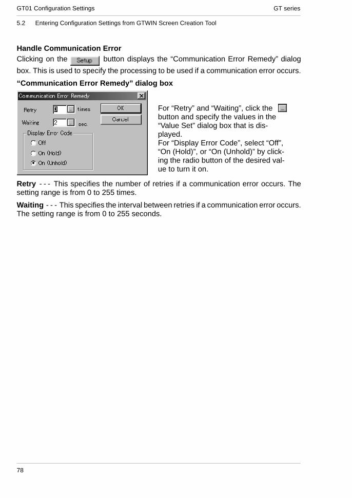
GT seriesGT01 Configuration Settings
78
5.2 Entering Configuration Settings from GTWIN Screen Creation Tool
Handle Communication ErrorClicking on the button displays the “Communication Error Remedy” dialog
box. This is used to specify the processing to be used if a communication error occurs.
“Communication Error Remedy” dialog box
For “Retry” and “Waiting”, click thebutton and specify the values in the“Value Set” dialog box that is dis-played.For “Display Error Code”, select “Off”,“On (Hold)”, or “On (Unhold)” by click-ing the radio button of the desired val-ue to turn it on.
Retry - - - This specifies the number of retries if a communication error occurs. Thesetting range is from 0 to 255 times.
Waiting - - - This specifies the interval between retries if a communication error occurs.The setting range is from 0 to 255 seconds.

GT01 Configuration SettingsGT series
79
5.2 Entering Configuration Settings from GTWIN Screen Creation Tool
“Display Error Code”This switches the setting for the error code display used if a communication erroroccurs.
Off - - - No error code is displayed if a communication error occurs.
On (Hold) - - - An error code is displayed at the upper right of the screen if acommunication error occurs, and continues to be displayed until the power supply isturned off.
On (Unhold) - - - An error code is displayed at the upper right of the screen if acommunication error occurs, and is cleared when the cause of the error is eliminated.
For contents of error codes, please see “Error Codes and How to Handle Them”on page 114.
TOOL Port (for GTWIN connection)This is used to specify the communication speed and transmission format when theGT01 is connected to a personal computer (GTWIN).
Clicking on the button displays a pull -down menu from which the value to be set can
be selected.
· Baud Rate - - - Select 9600, 19200 or 115200 bits/s.
· Data Length - - - This is fixed at “8 bits”.
· Stop Bits - - - This is fixed at “1 bit”.
· Parity Bit - - - Select “None”, “Odd”, or “Even”.
Through functionIf the “Forward only to the selected unit” check box is turned on, communication can becarried out via the through function only with unit numbers for a PLC received from ahigher-order personal computer or higher-order PLC.

GT seriesGT01 Configuration Settings
80
5.2 Entering Configuration Settings from GTWIN Screen Creation Tool
5.2.4 GT Configuration Settings: “Auto-Paging”
Clicking on “Auto-Paging” in the “GT Configuration” dialog box displays the screenshown below. Here, settings can be entered for a functions that automatically switchesthe screens displayed on the GT01.
“Auto-Paging” screen
Auto-pagingThis is used to specify the “Auto-paging function”, which automatically switches thespecified screen when a given period of time has elapsed.
Off - - - The screen is not switched automatically.
On - - - The screen is switched automatically, in conformance with the specifiedcontents.

GT01 Configuration SettingsGT series
81
5.2 Entering Configuration Settings from GTWIN Screen Creation Tool
Auto-paging settingsIf “On” is selected for auto-paging, and the [Setup] button is clicked, a dialog boxcontaining the following auto-paging settings is displayed.
Clicking on the button for “Screen No.”, “Time”, or “Jump to” displays a “Value Set”dialog box. Set the value and click the [Save] button to save values one at a time.
Screen No. - - - This specifies the screen targeted for auto-paging.
Time - - - This specifies the time for which the screen specified above is displayed. Thesetting range is from 1 to 255 seconds.
Jump to - - - This specifies the number of the next screen to be displayed.
[Return] - - - This completes the auto-paging settings and returns to the“Auto-Paging” dialog box.
[Delete] - - - This deletes screens registered for auto-paging.
[Save] - - - This saves the settings for the screen number, time, and jump destinationas auto-paging settings.

GT seriesGT01 Configuration Settings
82
5.2 Entering Configuration Settings from GTWIN Screen Creation Tool
5.2.5 GT Configuration Settings: “Startup Screen Settings”
Clicking on “Start -up Screen” in the “GT Configuration” dialog box displays the screenshown below. Here, the screen displayed when the GT01 is booted can be specified.
“Start -up Screen” screen
This is used to specify the screen that will be displayed when the GT01 is booted, aswell as the time it will be displayed. Clicking on the button for each of the itemsdisplays a “Value Set” dialog box where the values can be specified.
Start -up Screen No. - - - This specifies the number of the screen that will be displayedwhen the GT01 is booted. Clicking on the button displays a “Value Set” dialog boxwhere the value for the start -up screen number can be specified.
Display Time - - - This specifies the time for which the startup screen specified abovewill be displayed. The value can be set to any number between 0 and 255 seconds.Clicking on the button displays a “Value Set” dialog box where the start -up delaytime can be specified.
Key points
When the above settings are entered, the screen specified with the“Startup Screen No.” parameter is displayed for the amount of timespecified with the “Display Time” parameter.When the amount of time specified with the “Display Time” parameterelapses, the screen corresponding to the number stored in the initialaddress of the word device under “Basic Communication Area toPLC” in the “Basic Setup” parameters under “GT Configuration” willbe displayed.This function is used when it is necessary to delay the start -up timewhen the power supply on the PLC side is turned on.

GT01 Configuration SettingsGT series
83
5.2 Entering Configuration Settings from GTWIN Screen Creation Tool
CAUTION
Communication between the GT01 and the PLC (external device)cannot be carried out during the time specified by the “Display Time”parameter.

GT seriesGT01 Configuration Settings
84
5.2 Entering Configuration Settings from GTWIN Screen Creation Tool
5.2.6 GT Configuration Settings: “Setup”
Clicking on the “Setup” tab in the “GT Configuration” dialog box displays the screenshown below. Here, clock functions, backlight control, and other parameters can bespecified.
“Setup” screen
ClockClockThis is used to specify the reference destination for the clock displayed with the GT01.Select one of the radio buttons.
PLC Clock - - - When the time is displayed, the internal clock in the PLC is used as areference for the value.
If the “PLC Clock” is referenced for the clock setting, clicking on the button displaysa screen where the type of device and the address can be specified.
Device Setting dialog box
The button functions as a backspacekey when entering addresses.
The button acts as a Clear key.
Click on the button to display the pull -downmenu, and select the device from that menu.Enter the address using the ten-keys.

GT01 Configuration SettingsGT series
85
5.2 Entering Configuration Settings from GTWIN Screen Creation Tool
Backlight controlAuto-OffThis is used to specify the Auto-Off backlight feature.
Off - - - The Auto-Off backlight feature is not used.
On - - - Auto-Off backlight feature is used. This parameter specifies the period of timethat the GT01 is inactive before the backlight goes off automatically.
If “On” is set for the above Auto-Off backlight feature, clicking on the button displaysa screen where the time until the backlight goes off can be specified. Any time from oneminute to 30 minutes can be specified.
Key points
If the backlight is turned off automatically using the backlight controlfunction, touching the screen turns it on again. If a touch switchhappens to be located at that point on the screen, it will be invalid untilthe backlight has gone on again.
Touch SoundsThis sets the touch sounds corresponding to GT01 screens as either invalid or valid.Select one of the radio buttons.
Disable - - - Touch sounds are disabled.
Enable - - - Touch sounds are enabled.

GT seriesGT01 Configuration Settings
86
5.3 Entering Configuration Settings from the GT01 Main Unit
5.3 Entering Configuration Settings from the GT01 MainUnit
5.3.1 What is the System Menu?
The system menu is a dedicated screen on which configuration settings for the GT01are entered. Some of the items that can be specified here can also be set using GTWINscreen creation tool and then sent to the GT01, but others, such as the adjustments tothe LCD contrast level, can only be set using the system menu. This section explainshow configuration settings are entered using the system menu.
5.3.2 Bringing Up the System Menu
The following procedure is used to bring up the system menu.(1) Touch the LCD touch panel simultaneously.
1 Press the upper left corner (area A) for at least two seconds.2 Next, immediately press the upper right corner (area B) and
lower right corner (area C), in that order.*Press areas A, B and C, in order, individually. It will not work of you pressthem together.
*For vertical type displays, arrange vertically and then use the order of upperleft corner, upper right corner, and then lower right corner.
*The System Menu does not support vertical type displays. It will display thesame as on the horizontal type.
(2) The initial screen of the system menu is displayed.
The initial screen of the system menu is displayed onthe GT01. Touching either the [Setting] or [Test] keyshifts to the next screen.Touching the [ESC] key exits the system menu and re-turns to the normal operating mode.
“System Ver” indicates the ROM version of the GT01 system.
(3) Select the mode.[Setting]: Setting mode initial screen
This is where configuration settings for the GT01, suchas the contrast, clock, COM. port, TOOL port, andmemory, are specified.
[Test]: Test mode initial screen
This is where GT01 configuration elements such asthe touch switches, backlight, clock, buzzer, LCD,contrast, and memory are tested.
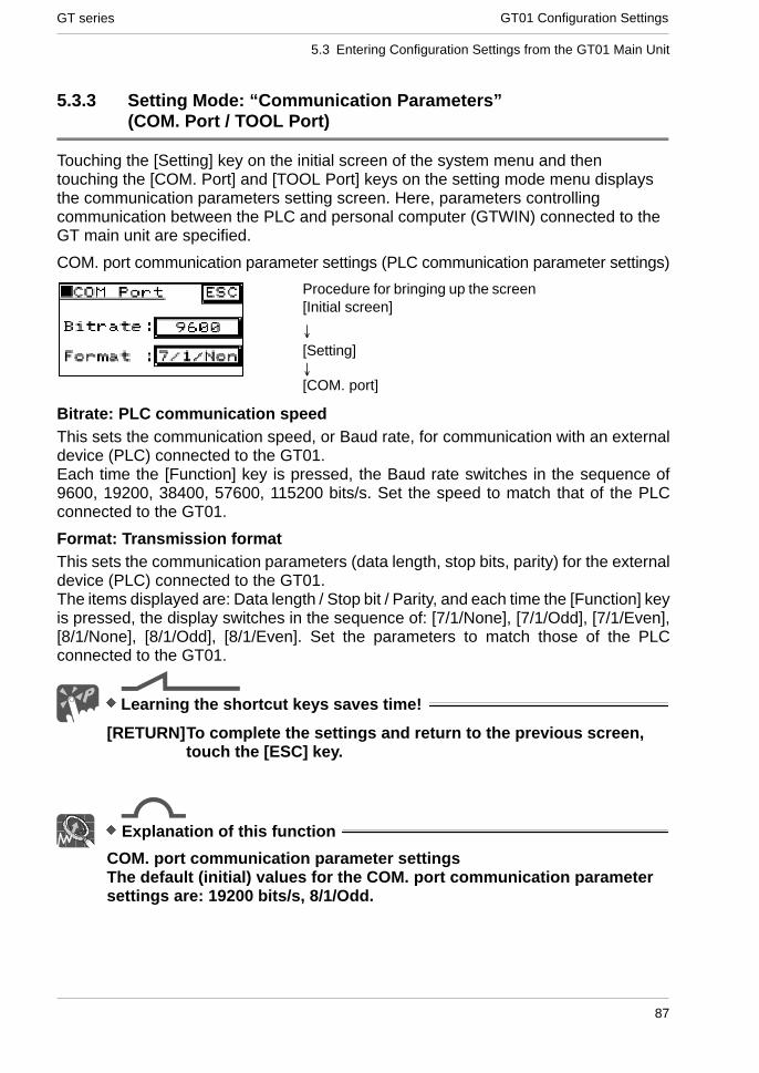
GT01 Configuration SettingsGT series
87
5.3 Entering Configuration Settings from the GT01 Main Unit
5.3.3 Setting Mode: “Communication Parameters”(COM. Port / TOOL Port)
Touching the [Setting] key on the initial screen of the system menu and thentouching the [COM. Port] and [TOOL Port] keys on the setting mode menu displaysthe communication parameters setting screen. Here, parameters controllingcommunication between the PLC and personal computer (GTWIN) connected to theGT main unit are specified.
COM. port communication parameter settings (PLC communication parameter settings)
Procedure for bringing up the screen[Initial screen]
[Setting]
[COM. port]
↓
↓
Bitrate: PLC communication speedThis sets the communication speed, or Baud rate, for communication with an externaldevice (PLC) connected to the GT01.Each time the [Function] key is pressed, the Baud rate switches in the sequence of9600, 19200, 38400, 57600, 115200 bits/s. Set the speed to match that of the PLCconnected to the GT01.
Format: Transmission formatThis sets the communication parameters (data length, stop bits, parity) for the externaldevice (PLC) connected to the GT01.The items displayed are: Data length / Stop bit / Parity, and each time the [Function] keyis pressed, the display switches in the sequence of: [7/1/None], [7/1/Odd], [7/1/Even],[8/1/None], [8/1/Odd], [8/1/Even]. Set the parameters to match those of the PLCconnected to the GT01.
Learning the shortcut keys saves time!
[RETURN]To complete the settings and return to the previous screen,touch the [ESC] key.
Explanation of this function
COM. port communication parameter settingsThe default (initial) values for the COM. port communication parametersettings are: 19200 bits/s, 8/1/Odd.

GT seriesGT01 Configuration Settings
88
5.3 Entering Configuration Settings from the GT10 Main Unit
TOOL Port communication parameter settings (GTWIN communication parametersettings)
Procedure for bringing up the screen[Initial screen]
[Setting]
[TOOL Port]
↓
↓
Through function: Through function destination settingWhen the through function is being used, this specifies the number of the PLC at theother end of the connection. Normally, when used in a 1 : 1 configuration, this shouldbe set to “00”.
Bitrate: GTWIN communication speedEach time the [Function] key is touched, the Baud rate switches in the sequence of9600/19200/115200 bits/s. Set the speed to match that of the personal computer(GTWIN) connected to the GT01.
Format: Transmission formatThis sets the communication parameters (data length, stop bits, parity) for the personalcomputer (GTWIN) connected to the GT01.The items displayed are: Data length / Stop bit / Parity, and each time the [Function] keyis pressed, the display switches in the sequence of: [8/1/None], [8/1/Odd], [8/1/Even].
Learning the shortcut keys saves time!
[RETURN]To complete the settings and return to the previous screen,touch the [ESC] key.
Explanation of this function
TOOL Port communication parameter settingsThe default (initial) values for the TOOL Port communication parametersettings are: 19200 bits/s, 8/1/Odd.

GT01 Configuration SettingsGT series
89
5.3 Entering Configuration Settings from the GT10 Main Unit
5.3.4 Setting Mode: “Liquid Crystal Display Contrast Adjustment”(Contrast)
Touching [Setting] on the initial screen of the system menu and then the [Contrast] keyof the setting mode menu displays the contrast adjustment screen. The contrast of theGT01 LCD is adjusted here.
Contrast adjustment screen
Procedure for bringing up the screen[Initial screen]
[Setting]
[Contrast]
↓
↓
Learning the shortcut keys saves time!
[ADJUST] Touching the [+] key increases the contrast, and touching the[- ] key decreases it.
[RETURN]To complete the settings and return to the previous screen,touch the [ESC] key.

GT seriesGT01 Configuration Settings
90
5.3 Entering Configuration Settings from the GT10 Main Unit
5.3.5 Setting Mode: “Memory Initialization” (Clear Memory)
Touching [Setting] on the initial screen of the system menu and then the [Memory] keyof the setting mode menu displays the memory initialization screen. The internal usermemory of the GT01 is initialized here.
Memory initialization screen
Procedure for bringing up the screen[Initial screen]↓[Setting]↓[Memory]
Touching the [SRAM] key deletes clock data and Hold PLC Device data held in theSRAM.
Touching the [FROM] key deletes screen data and main unit configuration settingssaved to the main unit user memory (F-ROM).
When either of the above keys is touched, a confirmation message readingis displayed. To clear the data, touch the key. A buzzer
sounds, and the memory is cleared. When the buzzer stops sounding, the memory hasbeen completely cleared.
Learning the shortcut keys saves time!
[RETURN]To complete the settings and return to the previous screen,touch the [ESC] key.
CAUTION
[SRAM] initialization deletes the Hold PLC Devicedata backed up in the SRAM. Please be sure that you wantto do this before initializing the SRAM.
[FROM] initialization deletes the base screen data, the main unitconfiguration setting data (the main unit configurationsetting data returns to the default values) and contrastadjustment setting data (the contrast returns to the defaultvalue) in the user memory (F-ROM) of the main unit. Beforeinitializing the F-ROM, always save screen data to a floppydisk or another medium with GTWIN.

GT01 Configuration SettingsGT series
91
5.3 Entering Configuration Settings from the GT10 Main Unit
5.3.6 Setting Mode: “Touch Switch Adjustment” (T. SW)
Touching [Setting] on the initial screen of the system menu and then the [T. SW] key ofthe setting mode menu displays the touch switch adjustment screen. The position of theGT01 touch switch is adjusted here.
Touch switch adjustment screenProcedure for bringing up the screen
[Initial screen]↓[Setting]↓[T. SW]
Learning the shortcut keys saves time!
[Adjust] Touch the “+” mark with a soft, narrow instrument. Touch the“+” mark three times as displayed on the screen. Pleaserepeat if the touch position has shifted greatly. You will notlose this setting when the power is turned off. The setting willbe initialized when the F-ROM memory is initialized.
[RETURN]To complete the settings and return to the previous screen,touch the [ESC] key.

GT seriesGT01 Configuration Settings
92
5.3 Entering Configuration Settings from the GT10 Main Unit
5.3.7 Test Mode: “Self -Diagnosis”
Touching the [Test] key on the initial screen of the system menu displays theself -diagnosis screen. This is used to run a hardware check of the memory, buzzers,and other elements of the GT01.
Test mode screen
Procedure for bringing up the screen[Initial screen]↓[Test] key
Touch SWThis runs an operation check of the touch switches.
B. LightThe color of the backlight changes at one-second intervals (in sequence from greena red a green a orange).
BuzzerThis runs an operation check of the buzzer.
LCDThis displays a pattern and runs an operation check of the display.
ContrastTouch the [+] and [ - ] keys to check changes in the contrast.
Learning the shortcut keys saves time!
[RETURN]To complete the settings and return to the previous screen,touch the [ESC] key.
Explanation of this function
Test mode (self -diagnosis) screenOn the test mode screen, the item name of the item that was justtested is highlighted.(The dots are cleared when the screen is returned to the initial screenof the system menu.)

GT01 Configuration SettingsGT series
93
5.3 Entering Configuration Settings from the GT10 Main Unit
5.3.8 Inhibiting the System Menu Display
In order to prevent unauthorized persons from being able to change GT01 configurationsettings, the GT01 is set up so that DIP switches can be used to make it impossible todisplay the system menu.
Switch no. Function OFF ON1 Usage inhibited Should always be in the
“OFF” position when unit isused.
2 Inhibits system menushift
Shift possible Shift inhibited
3 Usage inhibited Should always be in the“OFF” position when unit is
4“OFF” position when unit isused.
Operation mode setting switches
If the second operation mode setting switch isturned on, as shown at the left, access to thesystem menu is denied.

GT seriesGT01 Configuration Settings
94
5.3 Entering Configuration Settings from the GT10 Main Unit

Chapter 6
How the Various Functions Are Used

GT seriesHow the Various Functions Are Used
96

How the Various Functions Are UsedGT series
97
6.1 Switching Screens
6.1 Switching Screens
There are three ways to switch screens registered in the GT main unit.
6.1.1 Switching the Screen from the PLC
GT main unit screens can be switched from the PLC ladder program, by writing thenumber of the screen to be displayed in hexadecimal format to the initial word of theword device in the basic communication area.At the same time that the screen is switched, the GT main unit writes the number of thescreen to which the display was switched in the first to third words of the basiccommunication area, in hexadecimal format.How communication is carried out between the GT main unit and PLC (screenswitching)
GT main unitPLC
Basic communication area / word device
First word (specifies screen no. from PLC)
Second word (usage prohibited area)
Third word (no. of screen currently displayed)
Internal PLC device
Ongoingcommunication
How screens are switched
GT main unit PLC
GT main unitPLC
Screen No. 1
Screen No. 2
When Screen No. 2is specified by thePLC
the screenswitches toNo. 2
and the PLC is noti-fied that the screenhas been switched.
Basic communication area / word device
First word, HEX 2
Second word (usage prohibited area)
Third word, HEX 1
Basic communication area / word device
First word, HEX 2
Second word (usage prohibited area)
Third word, HEX 2
Example of ladder programBasic screen display program
X0[ F 0 MV , H 2 , D T 0 ]
No. of screendisplayed
Address of first word in basiccommunication area / word device
Condition thatdisplays screen
When the screen is switched as a means of triggering switch output from the displayunit, the destination for the switch output should be specified in the condition thatdisplays the screen, indicated in the sample program above.

GT seriesHow the Various Functions Are Used
98
6.1 Switching Screens
6.1.2 Switching the Screen with the GT Main Unit
Using the function switch unitGTWIN has “function switching parts” (FSW0, FSW1, FSW2) in the parts library that canbe used to switch screens on the GT main unit. These parts should be arranged on thebase screen and assigned the attributes indicated below.
Function switching parts: Attribute editing dialog box
Double-clicking on the parts arranged on the base screen, or selecting a switch part,and clicking on the “Parts (T)” menu and then the “Edit Attribute” sub-menu displaysthe dialog box shown above.
(1) Using the “Change Screen” operation modeSelect the “Change Screen” operation mode and specify the number of the screen tobe changed. Then press the switch part to switch the screen to the specified screen.To return to the screen displayed just prior to the currently displayed screen, the “Returnto Previous Screen” operation mode can be used.
In this case, the value of the third word in the basic communication area / worddevice (the number of the currently displayed screen) changes to that of the new screennumber, but please be aware that the contents of the first word (the screen numberspecified by the PLC) do not change. For detailed information, see page 101.

How the Various Functions Are UsedGT series
99
6.1 Switching Screens
(2) Using the “Value Set” operation modeSelect the “Value Set” operation mode and enter the following settings:- Data format: Specify 1 word- Output destination: Specify to first word of basic communication area / word device- Value: Number of screen to be changed to (hexadecimal specification)Each time the GT main unit switch part is pressed, the screen number is forcibly writtenby the GT main unit to the first word of the basic communication area / word device, andthe screen is switched.
If using this method, the values for both the first word of the basic communicationarea / word device (the screen number specified by the PLC) and the third word (thenumber of the currently displayed screen) are changed.

GT seriesHow the Various Functions Are Used
100
6.1 Switching Screens
Using the auto-paging functionThe GT main unit has an “Auto-paging” function that automatically switches the screento a specified screen number when a certain period of time has elapsed. This functioncan be used to switch screens automatically.
For information on setting the auto-paging function, please see page 81 (GT01).
If using this function, please be aware that the value of the third word in the basiccommunication area / word device (the number of the currently displayed screen)changes to that of the new screen number, but the contents of the first word (the screennumber specified by the PLC) do not change. For detailed information, see page 101.
Clicking on the button displays the value setting dialog box shown below. Specifythe number of the screen to which the display is to be changed.
Value Set dialog boxIf the value is entered with thebutton pressed as shown at the left, ahexadecimal screen number is speci-fied, and if the value is entered withthe button pressed, a decimalvalue is entered.
The button acts as a backspacekey when entering an address, and the
button functions as a Clear key.

How the Various Functions Are UsedGT series
101
6.1 Switching Screens
Key points
If the screen does not change as expectedIf the screen is changed from the PLC, and the GT main unit functionswitch parts are also used to change the screen (Change Screenoperation mode), a case sometimes occurs in which the screen doesnot change, even though an instruction to change the screen hasbeen issued by the PLC.
Example: Screen No. 1 is displayed in keeping with the instruction from the PLC, andthe screen is changed to Screen No. 2 using the function switch parts.
1
1
1
2
1
Screen No. 1Currently displayscreen number changes
Contents of basic communication area / word device
First word (screen no. instruction from PLC)
Third word (currently displayed screen no.)
Screen is switched in response to function switch parts (Change Screen operation mode)
Screen No. 2Change is not reflected
Currently displayedscreen no. is changed
First word (screen no. instruction from PLC)
Third word (currently displayed screen no.)
Screen changing instruction from PLC
Screen No. 2 Screen changinginstruction First word (screen no. instruction from PLC)
In this state, “1” is already written for the first word, so if an instruction is sent from thePLC to the first word to display Screen No. 1, it duplicates what is already written, and thescreen will not be switched.
Screen switchinginstruction

GT seriesHow the Various Functions Are Used
102
6.1 Switching Screens
This problem can be solved in the following manner:Use the “forced-display flag” in the basic communication area/bitdevice.
1) At the same time that the PLC issues an instruction to change thescreen again to Screen No. 1, or shortly after that point, theforced-display flag in the first word/Bit E of the basic communicationarea/bit device is turned on, using the bit as a PLC bit operationinstruction.
2) When the forced-display flag begins to go on, the screencorresponding to the number written to the first word of the basiccommunication area/word device, meaning Screen No. 1, is forciblydisplayed at the point that step 1 takes place. (This is carried out onlyat the rise of the forced-display flag).
3) After the screen has been switched, the forced-display flag shouldbe turned off.
Set the operation mode of the function switch parts to “Value Set”.When the screen is switched using the function switch parts, asshown in the illustration above, the operation mode of the functionswitch parts is set to “Value Set” in order to switch the screen. (Fordetailed information, see page 98.)Using the “Value Set” mode changes the contents of the first word inthe basic communication area/word device (the screen numberspecified by the PLC) and the third word (the number of the currentlydisplayed screen) to that of the new screen number, and thus avoidsthe kind of case described above.

How the Various Functions Are UsedGT series
103
6.2 Basic Communication Area to PLC and Bit Device Functions (GT01)
6.2 Basic Communication Area to PLC and Bit DeviceFunctions (GT01)
6.2.1 Bit Device Functions
In order for communication to be carried out between the GT01 and PLC, an internaldevice area like that shown below is provided in the PLC. This basic communicationarea contains two types of devices: word devices, which are used to handle screennumbers and other data, and bit devices, which are used for bit information. The variousbits of the bit devices are turned on and off from the PLC, and can be used to controlvarious GT01 operations.
Bit devicesWord position F E D C B A 9 8 7 6 5 4 3 2 1 0
N+0BZ Forced-
displayflag
BacklightValid flag
BacklightFlashing
BacklightColor
N+1 Usage prohibited
N+2Data InputIn Prog-ress flag
Explanation of system areas
BZ - - - This turns on the buzzer.Forced-Display flag - - - At the rise when the bit is turned on, the screen specified bythe PLC is forcibly displayed. (This is executed only when at the rise of the bit.)Backlight Valid flag - - - When the bit is turned on, the backlight flashing/backlightcolor control becomes effective.Backlight Flashing - - - 0: Lighted (normal), 1: FlashingBacklight Color - - - 00: Off, 01: Green, 10: Red, 11: OrangeData Input In Progress flag - - - This is 1 while data is being input, and 0 when datainput has been completed.
Explanation of this function
DT0 to DT2 and WR0 to WR2 are set as the default values for the basiccommunication area.For information on the contents of all areas of the basic communicationarea, please see page 30.

GT seriesHow the Various Functions Are Used
104
6.2 Basic Communication Area to PLC and Bit Device Functions (GT01)
Changing the backlight colorBits A and B of the first word of the bit device are used to change the backlightcolor. The color of the backlight can be changed by turning these bits on and off.To make these settings valid, however, Bit D (Backlight Valid flag) must alwaysbe turned on at the same time.Bit status Backlight color
B A
OFF OFF Off
OFF ON Green
ON OFF Red
ON ON Orange
Using a flashing backlightBit C of the first word of the bit device is used to make the backlight flash. The backlightstatus can be changed by turning this bit on and off. To make this setting valid, however,Bit D (Backlight Valid flag) must always be turned on at the same time.
Bit status Backlight status
C
OFF Lighted
ON Flashing
Making the buzzer soundBit F of the first word of the bit device is used to make the buzzer sound. The buzzerstatus can be changed by turning this bit on and off.
Bit status Buzzer status
F
OFF Stopped
ON Buzzer output
Data Input in Progress flagWith the GT01, while data is being input from the screen keyboard part, Bit 0 of the thirdword of the bit device is on.Applications should be set up so that, when this bit is on, the screen cannot be changedfrom the PLC.

Chapter 7
Servicing and Maintenance

GT seriesServicing and Maintenance
106

Servicing and MaintenanceGT series
107
8.3 Replacing the Front Panel Protective Sheet
7.1 Replacing the Front Panel Protective Sheet
7.1.1 About the Front Panel Protective Sheet
Protective sheets are available in order to protect the touch panel surface and to keepit clean. Please use the following separately-sold protective sheets if there is apossibility that the touch panel surface will become dirty.Product name Contents Product numberFront panel protective sheet Front panel protective sheets for replacement (set of 10) For GT01 AIGT080
7.1.2 Replacing the Front Panel Protective Sheet
Follow the steps below to replace the sheet:1. Remove the attached front panel protective sheet.First, peel off the front panel protective sheet already attached to the GT main unit,starting from the knob is.2. Peel off the seal from the provided protector sheet and attach it to the unit.Take out one of the replacement front panel protective sheets and peel off the seal withthe shiny side. When attaching the sheet, align the adhesive edges with the front of theGT main unit.3. Finish by peeling off the thin film attached to the top of the front panel protectivesheet.
Peel off the front film.
Front
Adhesive face (attached seal)

GT seriesServicing and Maintenance
108
8.4 Replacing the Waterproof Packing
7.2 Replacing the Waterproof Packing
7.2.1 About the Waterproof Packing
If the panel is being detached from the GT main unit and then reattached, the waterproofpacking should be replaced, in order to assure that the panel remains waterproof (IP65).Product name Contents Product numberWaterproof packing Waterproof packings for replacement (set of 10) For GT01 AIGT081
7.2.2 Replacing the Waterproof Packing
Follow the steps below to replace the packing:
1. Remove the currently attached waterproof packing.Remove the attached waterproof packing from the GT main unit.
2. Attach the provided waterproof packing.Take out one of the replacement waterproof packing pieces and attach the outer edgeas shown in the illustration (do not use the inner edge).When doing this, fasten it to the front frame, being sure not to twist the waterproofpacking.

Chapter 8
Troubleshooting

GT seriesTroubleshooting
110

TroubleshootingGT series
111
8.1 What to Do If Something Unusual Occurs (GT01)
8.1 What to Do If Something Unusual Occurs (GT01)
Problem Cause Solution Related
Screen isblank
1) Power is not on.
2) (When only lamp and message partsare configured to the base screen)Value of substitute reference devicevalue does not exist in substitute data.
1) Supply 5V DC power to unit.
2) Check the address of the substitutereference device and the device val-ues on the PLC side.
P.18
GTWIN HELP
Error code[ER**]appears atthe top rightof the screen
An error has occurred in communicationbetween the GT01 and an external de-vice (e.g. PLC).
[Troubleshooting error codes] are listedon P.114. Refer to this section for details.
P.114
Screendisplays[No Screendata]
There is no base screen data in theGT01. (Appears even when GT01 con-figuration data exists.)
Transfer base screen data from GTWIN. GTWIN HELP
Screendisplays[Screen No.Error]
1) Screen settings from the PLC, theGT01’s switch part or the auto-pagingindicate an unregistered screen num-ber.
2) When bringing up the keyboard screenduring data input, an unregistered key-board screen number was specified.
3) GT01 configuration data and keyboardscreen data exist in the GT01, butthere is no base screen data.
1) Create and register screen content orspecify the correct screen number.
2) Create and register keyboard screenor specify the correct keyboard num-ber.
3) Transfer base screen data fromGTWIN.
P.100
GTWIN HELP
GTWIN HELP
Screendisplays[Memory isFull]
The total capacity of transferred basescreen data exceeds the 384kbyte ca-pacity of the GT01.
Delete part of the base screen data sothat the total capacity doesn’t exceed384kbyte. Data capacity can be checkedby going to [View (V)] → [Memory UsageConditions] on GTWIN menu bar.When the data capacity is not over thelimit, invalid data could possibly be re-maining in the GT01 main unit. Whentransferring data, do so after deleting thescreen.
GTWIN HELP
Anunspecifiedscreenappeared /there istrouble whenswitchingscreens
1) The screen specification in the PLCscreen setting, the GT01 switch partor the auto-paging is wrong.
2) The startup screen is specified in theGT01 configuration settings (GTWIN).
3) An erroneous device or value is speci-fied in the first word of the basic com-munication area word device.
1) Specify the correct screen number.
2) Check the start -up screen setting forthe GT01 configuration settings inGTWIN. Delete unnecessary settingsand re- transfer configuration data.
3) Check the device content specified onthe PLC side in the first word of thebasic communication area. (Do notuse the basic communication areawith ladder programs.)
P.100
P.80
P.28 to P.30
Screendoesn’tswitch
1) No screen number has been written tothe screen setting area (the first wordin the basic communication area worddevice) from the PLC.
2) The screen number to which you areattempting to switch has already beenwritten from the PLC to the screen set-ting area (the first word in the basiccommunication area word device).
1) Specify correct screen number.
2) Refer to P.101 [If the screen does notchange as expected]. (Do not use thebasic communication area with ladderprograms.)
P.100
P.101

GT seriesTroubleshooting
112
8.1 What to Do If Something Unusual Occurs (GT01)
Problem Cause Solution Related
Screen isdim
1) The power voltage may be low.
2) The contrast is set too low.
3) The backlight is off due to the [Back-light Auto-off] setting in the [Setup] ofthe GT01 configuration settings inGTWIN.
1) Supply 5V DC 0.2 A.
2) Bring up the system menu and adjustthe contrast.
3) Touching any area of the screen lightsthat area. If a switch part is set on thetouched area, the area will not lighteven if touched. To change the setting,change the content of the backlightauto-off settings.
P.18
P.89
P.85
Backlightgoes off tooquickly
The backlight auto-off timer setting is tooshort.
Change the backlight auto-off timer set-ting.
P.85
Date / timedisplay isincorrect
1) The PLC’s internal calendar timerused as a reference is incorrect.
1) Adjust by rewriting the value in thePLC’s internal calendar timer.
All PLCmanuals
Touch paneldoesn’t work
1) Valid conditions have been set for theswitch part, but those conditions havenot been met. (Applies only to customparts.)
1) Check that the device status condi-tions on the PLC side are valid.
GTWIN HELP
No operatingsounds areheard whenthe touchpanel ispressed.
1) The [Switch Sounds] setting under[Options] in the switch part attributesis set to [Disabled].
2) The [Touch Sounds] setting under[Setup] in the GT01 configuration set-tings in GTWIN is set to [Disabled].
1) Change the setting to [Enabled].
2) Change the setting to [Enabled].
GTWIN HELP
Nothinghappens forabout 10secondsafter turningon power.
Communication conditions of GT (COMport) and PLC differ.
Verify communication settings of GT andPLC and then make them the same.
P.77

TroubleshootingGT series
113
8.1 What to Do If Something Unusual Occurs (GT01)
Problem Cause Solution Related
Buzzersoundscontinuously
Bit F of the first word in the basic com-munication area bit device is set to ON.
Set the F bit to OFF on the PLC side.(Do not use the basic communicationarea with ladder programs.)
P.103 to P.104
Backlightcolorchanges /flashes
Bits A and B, and Bit D, of the first word(backlight color setting) in the basic com-munication area bit device are set to ON.Or, Bits C and D (backlight flashing set-ting) are set to ON.
Perform correct bit operations on thePLC side. (Do not use the basic commu-nication area with ladder programs.)
P.103 to P.104
Cannottransfer datafrom GTWIN
1) The screen transfer cable is not con-nected.
2) The PC and GT01 COM. port are con-nected.
1) Confirm that the screen transfer cableis correctly and firmly connected.
2) Connect to TOOL port with screentransfer cable.
GTWIN HELP
* Screen isblank (powersupply andsubstitutionsettingsabove arecorrect)* Anincorrectscreen isdisplayed(error codesanderroneousdate andtime itemsnoted abovedo notapply)* Switchdoesn’t work(grid andvaliditysettingsnoted aboveare correct)
An error has occurred in the GT01 sys-tem.
1) After confirming the safety of the de-vice, etc., turn off the power supplyand then turn it on again. The GT01CPU will be reset.
2) If 1) produces no change, bring up thesystem menu and initialize thememory (F-ROM), then transfer dataagain from GTWIN to the GT01.CAUTION:When doing this, all base screen data,GT01 setting data, keyboard screendata, and bitmap data will be lost. Be-fore doing this, make sure all data hasbeen backed up.
3) If 2) produces no change, set the op-erating mode setting switches 2, 3 and4 on the rear of the GT01 to ON andreset the power supply.CAUTION:When doing this, all of the contents willrevert to those in effect at the time ofshipping, and all of the GT01 memorycontents will be cleared. Before doingthis, make sure all data has beenbacked up.
P.90

GT seriesTroubleshooting
114
8.2 Error Codes and How to Handle Them
8.2 Error Codes and How to Handle Them
8.2.1 About Error Codes
When an error occurs in the GT series, an error code displays at the top right of thescreen. There are two types of error codes, GT series error codes and PLC error codes.
ER XX Error code display
8.2.2 GT Series Error Codes
The following three types of error codes are displayed when there is an error in the GTmain unit:
Code no. Content Cause and solution
FF Time up errorNo response from the PLC.
1) The PLC connection cable is disconnected. Check the connectioncable to make sure it is connected.
2) There is a temporary error due to noise, etc. Re-supply power to thePLC and GT main unit.
21 Data errorA data error occurred dur-ing communication.
1) An error exists in the communication condition settings. Check thePLC and GT main unit communication speed and transfer format.
2) There is a temporary error due to noise, etc. Re-supply power to thePLC and GT main unit.
22 Overrun errorThe GT main unit cannotreceive data.
The reception buffer in the GT main unit is overflowing.There could be an error in the PLC.Re-supply power to the PLC and GT main unit.

TroubleshootingGT series
115
8.2 Error Codes and How to Handle Them
8.2.3 PLC Error Codes
When connected to a FP series PLCError codes which are sent from the PLC are listed in the table below. For details, pleaserefer to the separate [Computer Communication Unit Introductory Manual].
Code no. Content Cause and solution
21 Data errorA data error occurred during communication.
1) There is an error in the communication condi-tion settings. Check the PLC and GT01 com-munication speed and transfer format.
2) There is a temporary error due to noise, etc.Re-supply power to the PLC and GT01.
22 Overrun errorThe PLC isn’t receiving data.
The CPU unit’s reception buffer is overflowing.There could be an error in the PLC.Re-supply power to the PLC and GT01.
40 BCC errorA data error occurred during communication.
1) There is a temporary error due to noise, etc.Re-supply power to the PLC and GT01.
2) There is an error in the CPU unit. Re-supplypower to the PLC and GT01.
41 Format errorThe PLC has been sent a command that doesn’tmatch the protocol.
1) There is a temporary error due to noise, etc.Re-supply power to the PLC and GT01.
2) There is an error in the CPU unit. Re-supplypower to the PLC and GT01.
42 NOT support errorThe GT01 has sent a non-supported commandto the PLC.
1) There is a temporary error due to noise, etc.Re-supply power to the PLC and GT01.
2) There is an error in the CPU unit. Re-supplypower to the PLC and GT01.
53 BUSY errorThe PLC is currently processing another com-mand.
A large amount of data is being communicatedwith another RS232C port on the PLC.Wait until the error is gone.
61 Data run errorThere is an error in the register or relay number.
A register or relay number which doesn’t exist inthe PLC was specified during screen creationusing GTWIN.Correct the output device being used with thepart, or the transfer of clock data to an externaldevice.

GT seriesTroubleshooting
116
8.2 Error Codes and How to Handle Them
When Connecting a Mitsubishi Electric PLC (FX Series)The four following error codes are generated in the GT.
Code no. Content Cause and Countermeasure
FF Time up errorThere is no response fromthe PLC.
Check the wiring of the connection cable and check for disconnection.
10 Data errorAn abnormality occurred inthe data during commu-nication.
Check for errors in the communication conditions settings.
12 Overrun errorThe GT main unit does notaccept data.
PLC runaway might be the problem.
61 PLC errorA NAK error has been re-turned from the PLC.
Verify the PLC settings.
When Connecting an Omron PLCThe three following error codes are generated in the GT.
Code no. Content Cause and Countermeasure
FF Time up errorThere is no response fromthe PLC.
Check the wiring of the connection cable and check for disconnection.
10 Data errorAn abnormality occurred inthe data during commu-nication.
Check for errors in the communication conditions settings.
12 Overrun errorThe GT main unit does notaccept data.
PLC runaway might be the problem.
15 Numerical data errorDesignated read/write areais wrong.
Verify whether or not the reference device used with the basic commu-nication area and each part is a readable and writable area.
-Error codes other than these are based on Omron PLC error codes.
-Be sure to use the PLC in monitor mode. Otherwise, communication will not work properly.

TroubleshootingGT series
117
8.3 Table of Screen Messages
8.3 Table of Screen Messages
8.3.1 Table of GT01 Screen Messages
In addition to screen data, the GT01 also displays the following messages.
When transferring data from personal computer to a GT01This is displayed when data is being transferred from the computer to the GT01.
When transferring data from GT01 to a personal computerThis is displayed when data is being transferred from the GT01 to the computer.
When there is no base screen dataThis is displayed when there is no base screen data. (It is displayed even if theconfiguration data has been sent.)
When the specified screen does not existThis is displayed in cases such as when there is no data for a specified screen number.
When the screen memory is fullThis is displayed if the internal user memory (F-ROM) is full.

GT seriesTroubleshooting
118
8.3 Table of Screen Messages

Appendix
Information

Information GT series
120 Matsushita Automation Controls

InformationGT series
121Matsushita Automation Controls
A.1BIN/HEX/BCD Code Correspondence Table
A.1 BIN/HEX/BCD Code Correspondence Table
Decimal Hexadecimal Binary BCD code
0
1
2
3
4
5
6
7
0000
0001
0002
0003
0004
0005
0006
0007
00000000 00000000
00000000 00000001
00000000 00000010
00000000 00000011
00000000 00000100
00000000 00000101
00000000 00000110
00000000 00000111
0000 0000 0000 0000
0000 0000 0000 0001
0000 0000 0000 0010
0000 0000 0000 0011
0000 0000 0000 0100
0000 0000 0000 0101
0000 0000 0000 0110
0000 0000 0000 0111
8
9
10
11
12
13
14
15
0008
0009
000A
000B
000C
000D
000E
000F
00000000 00001000
00000000 00001001
00000000 00001010
00000000 00001011
00000000 00001100
00000000 00001101
00000000 00001110
00000000 00001111
0000 0000 0000 1000
0000 0000 0000 1001
0000 0000 0001 0000
0000 0000 0001 0001
0000 0000 0001 0010
0000 0000 0001 0011
0000 0000 0001 0100
0000 0000 0001 0101
16
17
18
19
20
21
22
23
0010
0011
0012
0013
0014
0015
0016
0017
00000000 00010000
00000000 00010001
00000000 00010010
00000000 00010011
00000000 00010100
00000000 00010101
00000000 00010110
00000000 00010111
0000 0000 0001 0110
0000 0000 0001 0111
0000 0000 0001 1000
0000 0000 0001 1001
0000 0000 0010 0000
0000 0000 0010 0001
0000 0000 0010 0010
0000 0000 0010 0011
24
25
26
27
28
29
30
31
0018
0019
001A
001B
001C
001D
001E
001F
00000000 00011000
00000000 00011001
00000000 00011010
00000000 00011011
00000000 00011100
00000000 00011101
00000000 00011110
00000000 00011111
0000 0000 0010 0100
0000 0000 0010 0101
0000 0000 0010 0110
0000 0000 0010 0111
0000 0000 0010 1000
0000 0000 0010 1001
0000 0000 0011 0000
0000 0000 0011 0001
63:
255:
9999
003F:
00FF:
270F
00000000 00111111:
00000000 11111111:
00100111 00001111
0000 0000 0110 0011:
0000 0010 0101 0101:
1001 1001 1001 1001

Information GT series
122 Matsushita Automation Controls
A.2 ASCII Code Table
A.2 ASCII Code Table
b7
b6 0 0 0 0 1 1 1 1
b5 0 0 1 1 0 0 1 1
b4 0 1 0 1 0 1 0 1
b7 b b b b b b bASCII HEX
Most significant digit
b7 b6 b5 b4 b3 b2 b1 b0ASCII HEXcode
0 1 2 3 4 5 6 7
0 0 0 0 0 NUL DEL SPACE 0 @ P ‘ p
0 0 0 1 1 SOH DC1 ! 1 A Q a q
0 0 1 0 2 STX DC2 ” 2 B R b r
0 0 1 1 3 ETX DC3 # 3 C S c s
0 1 0 0 4 EOT DC4 $ 4 D T d t
0 1 0 1 5 ENQ NAK % 5 E U e u
0 1 1 0
digi
t 6 ACK SYN & 6 F V f v
0 1 1 1
fican
tdi
7 BEL ETB ’ 7 G W g w
1 0 0 0
stsi
gnifi
8 BS CAN ( 8 H X h x
1 0 0 1 Leas
t
9 HT EM ) 9 I Y i y
1 0 1 0 A LF SUB * : J Z j z
1 0 1 1 B VT ESC + ; K [ k
1 1 0 0 C FF FS , < L ¥ l |
1 1 0 1 D CR GS - = M ] m
1 1 1 0 E SO RS . > N ^ n ~
1 1 1 1 F SI US / ? O _ o DEL

InformationGT series
123Matsushita Automation Controls
A.3 Cable Specifications
A.3 Cable Specifications
A.3.1 PLC Communication Cable: Mini-DIN 5-pin Loose-Wire(AIGT8142)
3
54
1
2Mini-DIN plug side signals
Signal Name1 SG
SDRD
2345
Wire colorBrownRed
Orange
+5V WhiteBlackSHELL Shield
SHELL
7/0.28
30/1.18
2000/78.74 (Unit: mm/inch)
Pin no.
A.3.2 Mitsubishi Electric FX series PLC TOOL Port Connecting Cable(AIGT8152)
Specifications Product No.
AIGT8152
L
2m/6.56 ft.Mini-DIN 8-pin
Single-side6 loose wires
(Unit: mm/inch) Mini-DIN plug side signals
3
541
2 8
67
2000/78.74
50/1.977/0.28
1 -RD+RDSG
234
5 +5V
+SD
SHELL
67
8
-SD
GreenYellowBrown
WhiteOrange
Red
Pin No. Abbreviation Wire color
A.3.3 PLC Communication Cable: Mini-DIN 5-pin Loose-Wire(AIGT8162)
3
54
1
2Mini-DIN plug side signals
Signal Name1 SG
SDRD
2345
Wire colorBrownRed
Orange
BlackSHELL Shield
SHELL
7/0.28
30/1.18
2000/78.74 (Unit: mm/inch)
Pin no.

Information GT series
124 Matsushita Automation Controls
A.3 Cable Specifications
A.3.4 PLC Communication Cable: D-SUB 9-pin Loose-Wire(AIGT81842)
12345
6789
L 50/1.95
10/0.39 (shielded mesh wire section)
(Unit: mm/inch)
Pin No. Wire color Dot mark1 Brown Black
BrownYellow
Red
Red
Red
Specifications
D-SUB side signals
Product No.
AIP81842
L
2m/6.56 ft.D-SUB 9-pinSingle-sideloose wire
Black
BlackYellowGreen
Green
23456789

InformationGT series
125Matsushita Automation Controls
A.4Summary of Features and Compatible Versions
A.4 Summary of Features and Compatible Versions
The following table gives each function with the compatible models and versions.
GT01 GT10 GT30
TrueType fonts Ver. 1.0 and higher Ver. 2.0 and higher Ver. 1.0 and higher
Vertical display Ver. 1.1 and higher Ver. 2.0 and higher Not supported
Direct replacement method of custom parts Ver. 1.0 and higher Ver. 2.0 and higher Ver. 1.0 and higher
Sequential line graph Ver. 1.0 and higher Not supported Ver. 2.0 and higher
Alarm list tracking Not supported Not supported Ver. 2.0 and higher
Recipe Ver. 1.0 and higher Not supported Ver. 2.0 and higher
Password Ver. 1.0 and higher Not supported Ver. 2.0 and higher
Running display Ver. 1.0 and higher Not supported Ver. 2.0 and higher
Device writing Ver. 1.0 and higher Not supported Ver. 2.0 and higher
Floating point and scaling of data parts Ver. 1.0 and higher Not supported Ver. 2.0 and higher

Information GT series
126 Matsushita Automation Controls
A.4 Summary of Features and Compatible Versions

Record of changesGT series
Record of changesManual No. Date Description of Changes
ARCT1F381E APR.2003 First edition
ARCT1F381E-1 Oct. 2003 2nd edition (PDF only)- Addition of RS422 Type
ARCT1F381E-2 Dec. 2003 3rd edition (PDF only)
- Addition of 24 V model
ARCT1F381E-3 Mar. 2004 4th edition (PDF only)
- Supplementary explanation


Please contact ..........
ARCT1F381E-3 200404ACG-M381E-3
Specifications are subject to change without notice. Printed in Japan.
Automation Controls CompanyK Head Office: 1048, Kadoma, Kadoma-shi, Osaka 571-8686, JapanK Telephone: +81-6-6908-1050K Facsimile: +81-6-6908-5781http://www.nais-e.com/
All Rights Reserved © 2004 COPYRIGHT Matsushita Electric Works, Ltd.
Matsushita Electric Works, Ltd.
These materials are printed on ECF pulp.These materials are printed with earth-friendly vegetable-based (soybean oil) ink.