technical manual centrifugal fan - · pdf filetechnical manual ventmeca ge 2005 revision 2 1...
TRANSCRIPT
TECHNICAL MANUAL VENTMECA Ge 2005 Revision 2 1
Technical Manual Centrifugal Fan VENTMECA 41 Rue Sartoris 92254 La Garenne Colombes (France) Phone: 00 33 (0)1 42 42 65 69 Fax: 00 33 (0)1 47 60 05 63 E-mail: [email protected]

TECHNICAL MANUAL VENTMECA Ge 2005 Revision 2 2
SAFETY INSTRUCTIONS Read the instructions in this manual and the instructions appearing directly on the fan, if any, very carefully, paying special attention to safety recommendations. Persons assigned to any work throughout the life of the fan shall have specific technical skills, technical capabilities and acquired and recognized experience in this specific sector; they shall also have the necessary working tools and appropriate protective safety equipment, and shall know how to use them. There will be a danger to the safety and health of personnel if any of these required conditions is not satisfied. The fan may only be used for applications intended by the manufacturer. If it is used for improper purposes, it can cause reduce safety and cause injury to personnel, and cause economic losses. The Manufacturer designed this fan for industrial use in non-explosive zones. The fan shall be maintained under conditions of maximum efficiency by performing the programmed maintenance operations. Good maintenance is necessary for good performances, longer operating life and to maintain safety conditions at all times. When carrying out maintenance operations in zones that are hazardous or difficult to access, define appropriate safety conditions satisfying the safety laws in force on the workstation, to assure the safety of yourself and of others. Maintenance, Inspection and Repair activities shall be carried out only by an official maintenance agent, aware of the hazard conditions. Therefore, operational procedures for the complete machine shall be defined so as to manage hazard situation that might arise and methods of avoiding such situations. The expert maintenance agent shall always be extremely careful and pay special attention to his work, scrupulously respecting safety standards. During operation, always wear clothing and / or individual protection equipment indicated in usage instructions supplied by the manufacturer and as defined by the laws in force on work safety. Replace worn parts by original spare parts. Use oil and grease recommended by the manufacturer. Polluting materials shall not be disposed of in unapproved locations. They shall be disposed of in accordance with the applicable regulations in force. After changing lubricants, clean the fan surfaces and the floor surrounding the work area. EQUIPMENT RECEPTION Each fan shall be carefully inspected before shipment. When the equipment is received, check that the fan has not been damaged during transport, and make a written statement to the transporter if there is any damage. The transporter is responsible for any damage that occurred during transport. Also check that no water has penetrated into the motor, the bearings or any other sensitive parts of the fan. Use a crane or a forklift truck for lifting, always put hooks in the lifting points. Special attention shall be paid during the displacement. Never leave the load suspended. IMPORTANT Never use the motor lifting points for handling the fan.
TECHNICAL MANUAL VENTMECA Ge 2005 Revision 2 3
STORAGE Fans shall be stored in a closed dust free location at a temperature between +5°C and + 45°C and with a relative humidity not exceeding 80%. Close off intake and discharge openings to prevent any objects from accidentally dropping into the casing. Slacken and remove the belts if necessary (in this case, the removed belts shall be stored in a dry and cool location). WARNING The efficiency of oil and grease can be reduced during a long storage period. Consequently, it is important to top up the bearings with grease or oil monthly and to turn the fan by hand (about 100 turns) to prevent seizure and oxidation of the bearings. Before starting up after 2 years of storage, make a complete oil or grease change and inspect the trunking and belts. INSTALLATION The fan shall be placed to assure the minimum space necessary for correct operation and to provide good access for maintenance and servicing. The distance “D” between an obstacle and an unconnected fan shall be greater than or equal to the intake diameter. We recommend that a safety barrier should be placed in front of the intake and discharge of fans not connected to a network, to prevent accidents.

TECHNICAL MANUAL VENTMECA Ge 2005 Revision 2 4
1 – GENERAL INSTRUCTIONS CHECK THE FOLLOWING BEFORE STARTING: A. all bolts are correctly tightened. B. the bearings are lubricated, and the lubrication system (if any) is operating correctly. C. motor transmission devices are aligned in accordance with the instructions. D. the wheel turns freely. E. the flexible trunking between the fan and ducts is correctly installed. F. the required protective guarding is installed. G. the tilter or the damper, if any, is installed in accordance with the instructions. H. no tools or other objects have been forgotten inside the fan or the ducts. I. operation and startup of the fan cannot cause any damage to the installation to which it is connected. START THE FANS AND CHECK THAT: A. the direction of rotation is correct. B. there are no vibrations or abnormal noise. C. the bearing temperatures are normal. D. the lubrication system, if any, is working correctly. E. the temperature of the stuffing box, if any, is normal. F. the tilter or the damper control system is working correctly. AFTER STARTUP, CHECK THAT: A. the fan is working correctly throughout its operating range. B. the temperatures of the bearings and the stuffing box, if any, are within allowable limits.

TECHNICAL MANUAL VENTMECA Ge 2005 Revision 2 5
2 – CHECKS BEFORE STARTUP A. Tightness of fasteners
• Anchor bolts / floor • Front pads / frame • Bearing pedestals / frame • Motor / Frame • Bearings / pedestals • Caps / Bearings • Hub / Shaft assembly • Intake / Casing • Casing / Frame • Hoods / Casing • Casing / Casing • Dampers / Casing • Servomotor / Damper • Miscellaneous fasteners. B. Lubrication of bearings • Open the bearing and check the lubricant quantity, quality and distribution, for bearings with grease. • For oil lubrication, check the oil level. • Check the operating parameters of lubrication systems (see special instructions). C. Alignment • Axial clearances • Radial clearances. D. Free Rotation of the Wheel • Radial clearance between the wheel and the intake • Operation of the sealing devices without tightening excessively. • Turn the rotor and motor assembly by hand. E. Connections • No displacement of the trunking • The trunking is not squeezed before startup • There are no loads on the fan flanges. F. Protections • On the couplings • On the cooling disk • On the shaft between bearings • Grilles on the intake • Grilles on the discharge.

TECHNICAL MANUAL VENTMECA Ge 2005 Revision 2 6
G. Adjustments • Damper or tilter blades: pre-rotation direction of gas flow at the wheel entry H. Foreign bodies • Inspection of the fan • Inspection of the duct network. I. Protection of the installation • Authorization for startup by the site manager • Damper or tilter closed for startup. 3 – CHECKS DURING STARTUP A. Direction of rotation B. Vibrations and noise • Fan bearing on the coupling side • Axial • Vertical • Horizontal • Noise • Fan bearing opposite the coupling side • Axial • Vertical • Horizontal • Noise • Motor bearing on the coupling side • Axial • Vertical • Horizontal • Noise • Motor bearing opposite the coupling side • Axial • Vertical • Horizontal • Noise
TECHNICAL MANUAL VENTMECA Ge 2005 Revision 2 7
C. Bearing temperatures • Fan bearing on the coupling side 15 minutes after startup • Fan bearing opposite the coupling side 15 minutes after startup D. Oil circulation • Check levels • Check temperatures • Check flows E. Seal at shaft crossing • Temperature rise F. Flow adjustment • Main power supply to Servomotor • Voltage / Pressure • Regulation signal • Voltage / Pressure • Operation of limit switch • Operation of regulation 4 – CHECKS AFTER STARTUP A. Operation over entire adjustment range • Vibration • Noise • Current at maximum flow (contractual). B. Bearing temperature changes • Every fifteen minutes for one hour • Every hour for six hours • Temperature of seal.
TECHNICAL MANUAL VENTMECA Ge 2005 Revision 2 8
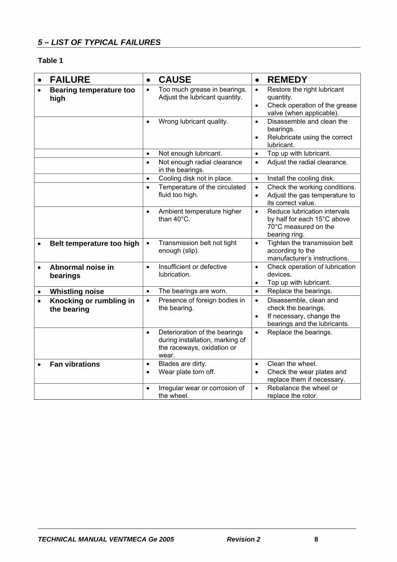
5 – LIST OF TYPICAL FAILURES Table 1 • FAILURE • CAUSE • REMEDY • Bearing temperature too
high • Too much grease in bearings.
Adjust the lubricant quantity. • Restore the right lubricant
quantity. • Check operation of the grease
valve (when applicable). • Wrong lubricant quality. • Disassemble and clean the
bearings. • Relubricate using the correct
lubricant. • Not enough lubricant. • Top up with lubricant. • Not enough radial clearance
in the bearings. • Adjust the radial clearance.
• Cooling disk not in place. • Install the cooling disk. • Temperature of the circulated
fluid too high. • Check the working conditions. • Adjust the gas temperature to
its correct value. • Ambient temperature higher
than 40°C. • Reduce lubrication intervals
by half for each 15°C above 70°C measured on the bearing ring.
• Belt temperature too high • Transmission belt not tight enough (slip).
• Tighten the transmission belt according to the manufacturer’s instructions.
• Abnormal noise in bearings
• Insufficient or defective lubrication.
• Check operation of lubrication devices.
• Top up with lubricant. • Whistling noise • The bearings are worn. • Replace the bearings. • Knocking or rumbling in
the bearing • Presence of foreign bodies in
the bearing. • Disassemble, clean and
check the bearings. • If necessary, change the
bearings and the lubricants. • Deterioration of the bearings
during installation, marking of the raceways, oxidation or wear.
• Replace the bearings.
• Fan vibrations • Blades are dirty. • Wear plate torn off.
• Clean the wheel. • Check the wear plates and
replace them if necessary. • Irregular wear or corrosion of
the wheel. • Rebalance the wheel or
replace the rotor.
TECHNICAL MANUAL VENTMECA Ge 2005 Revision 2 9
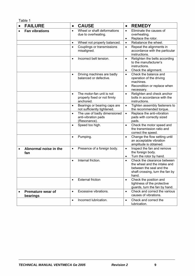
Table 1 • FAILURE • CAUSE • REMEDY • Fan vibrations • Wheel or shaft deformations
due to overheating. • Eliminate the causes of
overheating. • Replace the rotor.
• Wheel not properly balanced. • Rebalance the wheel. • Couplings or transmissions
misaligned. • Repeat the alignments in
accordance with the particular instructions.
• Incorrect belt tension. • Retighten the belts according to the manufacturer’s instructions.
• Check the alignment. • Driving machines are badly
balanced or defective. • Check the balance and
operation of the driving machines.
• Recondition or replace when necessary.
• The motor-fan unit is not properly fixed or not firmly anchored.
• Retighten and check anchor bolts in accordance with the instructions.
• Bearings or bearing caps are not sufficiently tightened.
• Tighten assembly fasteners to the recommended torque.
• The use of badly dimensioned anti-vibration pads (Resonance).
• Replace the anti-vibration pads with correctly sized pads.
• Speed too high. • Check the motor speed and the transmission ratio and correct the speed.
• Pumping. • Change the flow setting until an acceptable vibration amplitude is obtained.
• Abnormal noise in the fan
• Presence of a foreign body. • Inspect the fan and remove the foreign body.
• Turn the rotor by hand. • Internal friction. • Check the clearance between
the wheel and the intake and between the seal and the shaft crossing, turn the fan by hand.
• External friction • Check the position and tightness of the protective guards, turn the fan by hand.
• Premature wear of bearings
• Excessive vibrations. • Check and correct the various causes of vibrations.
• Incorrect lubrication. • Check and correct the lubrication.

TECHNICAL MANUAL VENTMECA Ge 2005 Revision 2 10
Table 1 • FAILURE • CAUSE • REMEDY • Premature wear of
bearings • Fan held stopped under
excitation by external vibrations.
• Eliminate vibrations by isolating machines causing excitement and isolate the fan itself.
• Fan held stopped without taking precautions against corrosive agents.
• Take steps made necessary by environmental and usage conditions:
• Intermittent operation • provide protected storage
during stoppages • - keep warm during
stoppages, etc. • Impossible or very long
to start • Rotor blocked. • Check that the rotor turns by
hand. • Search for the cause of the
blockage. • friction, • foreign bodies, etc.
• Voltage at motor terminals too low.
• Check the network voltage. • Improve the electrical line if
losses are excessive. • Trips. • Check the settings of safety
devices • Insufficient motor power. • Replace the motor. • Improper starter. • Replace the starter. • Excessive power absorbed
during start up. • Check that fan regulation
devices are closed when starting.
• Excessive power absorbed in service
• Excessive speed. • Check motor speed and transmission ratios and correct if necessary.
• Network less resistant than expected.
• Use the regulation devices to adjust the flow to its design value.
• Performances not obtained
• Speed too low. • Check motor speed and transmission ratio and correct if necessary.
• Adjust the belt tension. • Poor design of the intake and
discharge network. • Change the arrangement and
size of the network. • Incorrect direction of rotation. • Changeover the motor
direction of rotation. Performances not obtained • Wheel installed backwards
(double intake). • Invert the installation of the
wheel on the shaft. • Excessive clearances
between the wheel and the intake.
• Adjust the clearances to comply with the instructions.
TECHNICAL MANUAL VENTMECA Ge 2005 Revision 2 11
6 – CLEANING AND BALANCING Dust deposits can occur in some installations, or wheel wear can occur that can cause unbalance and consequently damage to the bearings. Severe dirt accumulation can also reduce fan performances. In this case, the fan must be cleaned or the wheel rebalanced. A special procedure shall be written to take account of the risk of dirt accumulation and the user shall follow it carefully. A systematic check on vibrations will help to detect any operating anomalies of the fan. Allowable vibration amplitudes are defined below. All measures shall be taken to limit dirt accumulation to a minimum value and to assure that it cannot reach a dangerous value. Washing manifolds, rotary brushes and other mechanical or automatic cleaning systems are very useful but their efficiency remains limited. Consequently, the most efficient solution when there is a high concentration of dirt is manual cleaning using a brush. All surfaces must be cleaned, because imperfect or incomplete cleaning can cause higher fan vibrations than before cleaning. Periodic inspections shall be carried out to detect dirt accumulation, corrosion or erosion. The wheel was designed, selected and manufactured taking account of all precautions necessary for the service conditions specified by the fan user; consequently, VENTMECA cannot be held responsible for corrosion, erosion, dirt accumulation, improper use or operation beyond the acceptable vibration amplitude. Similarly, we cannot be held responsible for harmful consequences resulting from operation of the fan outside the acceptable temperature range. Nothing could be written in this instruction manual that would increase safety and reliability in operation of the fan more than a special well-adapted programmed maintenance procedure, applied at appropriate times.

TECHNICAL MANUAL VENTMECA Ge 2005 Revision 2 12
7 – VIBRATION AMPLITUDES Table 2
ACTION VIBRATION VELOCITY
RMS velocity mm/s
GOOD 0 – 4.4 CHECK AT REGULAR INTERVALS 4.4 – 7.1 CHECK AT REGULAR INTERVALS AND REBALANCE AS SOON AS POSSIBLE
7.1 – 11.2
CLEAN AND REBALANCE 11.2 – 18 STOP IMMEDIATELY 18.0 ALARM 11.2 TRIP 18.0 8 – LUBRICATION OF OIL-LUBRICATED BEARINGS Follow the manufacturer’s instructions. 9 –OIL LUBRICATION UNIT Follow the manufacturer’s instructions. 10 – LUBRICATION OF GREASE-LUBRICATED BEARINGS Bearings are provided with grease nipples and are delivered containing sufficient grease for start up. Intervals between lubricating operations and grease quantities used are given in Table 3 and in Diagram 4. This table is produced for a bearing temperature of 70°C, measured at the outer bearing ring. For higher temperatures, intervals between lubricating operations shall be halved for each 15°C above 70°C.

TECHNICAL MANUAL VENTMECA Ge 2005 Revision 2 13
Table 3: Grease quantity (grams) SHAFT INITIAL ASSEMBLY SERVICING MAINTENANCE
∅ mm Series SNH-5-TG
Series SNH-6-TG
Series SNH-5TG
Series SNH-6-TG
20 25 g 5 g 25 40 g 50 g 5 g 10 g 30 50 g 60 g 10 g 10 g 35 65 g 75 g 10 g 10 g 40 80 g 100 g 15 g 15 g 45 100 g 150 g 18 g 22 g 50 130 g 180 g 20 g 26 g 55 150 g 230 g 15 g 20 g 60 190 g 280 g 20 g 25 g 65 240 g 430 g 20 g 40 g 70 280 g 480 g 25 g 50 g 75 330 g 630 g 27 g 55 g 80 430 g - 40 g - 85 480 g 850 g 50 g 70 g 90 630 g 1000 g 55 g 80 g
100 850 g - 70 g - 110 1000 g - 80 g - 115 1100 g - 95 g - 125 1400 g - 110 g - 135 1700 g - 130 g - 140 2000 g - 150 g -
IMPORTANT: Always clean grease nipples before lubricating so as to prevent foreign bodies from entering with the grease. IMPORTANT: 1. Always clean grease nipples before lubricating so as to prevent foreign bodies from entering with the grease. 2. In priority, follow the instructions on the lubrication plate fixed to the bearing pedestal. 3. When taking out of storage or after a prolonged shutdown of more than 1 year, top up with grease in each grease nipple before starting up.

TECHNICAL MANUAL VENTMECA Ge 2005 Revision 2 14
TABLE 4: LUBRICATION INTERVALS FOR GREASE-LUBRICATED BEARINGS Intervals between lubricating operations Hours of operation
n rpm tta Ball bearings ttb Roller bearings ttc Self-aligning roller bearings, tapered roller bearings Cylindrical roller bearings (0.2 ttc) Ball thrust bearings, roller thrust bearings (0.5 ttc) 11 – GREASE TYPES The grease types given in the following table are recommended for normal bearing temperatures between -30°C and +110°C and can be mixed with each other.

TECHNICAL MANUAL VENTMECA Ge 2005 Revision 2 15
TABLE 5: GREASE TYPES RECOMMENDED FOR LUBRICATION OF BEARINGS FLUID TEMPERATURE °C
AMBIENT TEMPERATURE °C
GREASE REFERENCE
GREASE BRAND
20°C + 130°C
20°C + 45°C
• ROLEXA 2 • ELF ANTAR
• ALVANIA R2 • MOBILPLEX 47 • ENERGREASE
LS2 • BEACON 2
• SHELL • MOBIL • BP • ESSO
135°C + 700°C 30°C + 60°C • STATERMA MO2 • ELF ANTAR • DARINA R2
• MOBIL TEMP 78 • ENERGREASE
LS3 • NORVA 275
• SHELL • MOBIL • BP • ESSO
* Our bearings will be delivered at the factory outlet lubricated with ROLEXA 2 type grease for fluid temperatures between 20°C and 130°C and with STATERMA MO2 type grease for fluid temperatures between 135°C and 700°C. Please call VENTMECA for temperatures outside the above limits, and VENTMECA will recommend the appropriate grease quality for each individual case. 12 – CHECK OF BEARINGS The behavior of bearings shall be checked at regular intervals during operation (for example when lubricating or changing the oil), by listening to their rotation noise or measuring their temperature. A daily or monthly inspection shall be carried out depending on the importance of the installation. The bearings shall be completely cleaned and examined annually. Use white spirit or a similar solvent for cleaning. Installing “VIBROCONTROL” type temperature sensors and vibration measurement sensors connected to a control cabinet as an “option” makes it possible to continuously check the installation. 12- 2 – BEARING TEMPERATURE A continuous or intermittent check on the bearing temperature can be made using a temperature sensor applied in contact with the outer bearing ring or embedded in the bearing pedestal through lubrication hole. A temperature of 70°C is normal. Temperatures shall be verified at frequent intervals for temperatures between 70°C and 85°C and an alarm must be triggered at 85°C. The fan must be stopped if the temperature reaches 95°C
TECHNICAL MANUAL VENTMECA Ge 2005 Revision 2 16
13 – ASSEMBLING AND ADJUSTMENT OF THE BEARINGS ASSEMBLY, DISASSEMBLY AND ADJUSTMENT OF BEARINGS WITH CYLINDRICAL BORE GENERAL The bearings must be handled carefully and protected against dust and humidity. They shall be kept in their original packaging until it is time for their assembly. The antirust product with which bearings are coated must generally not be removed, to avoid the risk of impurities entering the bearings. When bearings have to be cleaned, use white spirit or a similar solvent. Oil bearings immediately after cleaning. Shaft ends and bearings shall be cleaned and oiled before assembly. Do not tap directly on the bearing. Assembly and disassembly forces must not be transmitted through rolling elements. Adjustment surfaces must be lightly oiled. Assembly of bearings with conical bore (tightening sleeve) A screwdriver can be used to open the slit, to facilitate displacement of the sleeve along the shaft. The bearing is usually tightened using the nut on the sleeve. Fix the nut in position by using a hammer to tap gently on a bronze drift engaged in the tightening notches. The use of an impact wrench is recommended in difficult cases (for example roller bearing or large ball bearings). The lock washer is oriented such that the tabs are folded down outwards and the nut is inserted with the chamfer on the bearing side. Assembly of bearings with cylindrical bore The assembly is specific to double single-piece bearings. Always put the outer rings onto the shaft first. The bearings may be heated to a temperature of not more than 120°C in an oil bath or a drying oven. If necessary, the bearing can be forced into contact with its shoulder using a mild steel bushing driven by a hammer or a screw placed at the shaft end.

TECHNICAL MANUAL VENTMECA Ge 2005 Revision 2 17
Adjusting the bearings Respect clearances given in the manufacturer’s instructions. See the particular appendix for the equipment delivered on your fan. The operating clearance of the spherical roller bearings can be adjusted during assembly by measuring the reduction in the axial clearance or by measuring the axial displacement of the bearing on the tightening cone. In this type of bearing, the initial clearance and the expansion of the inner ring necessary for a tight fit shall be sufficiently large so that the internal clearance can be easily measured. The measurement is usually made using calibrated shims, with the thinnest shim being 0.03 mm thick. The measurement is always made between the outer ring and the unloaded roller, with the roller being pushed inwards during the operation. Firstly, turn the bearing by hand so that the rollers fit correctly into position. The same clearance must be obtained for the two rows of rollers. Tests Lubricate the bearings after assembly and carry out a rotation test during which the temperature rise and bearing noise shall be monitored. You can listen to a bearing through a tool wooden handle or a screwdriver placed between the bearing pedestal and your ear. Normally, you should hear an almost pure tone! A whistling noise is a sign of insufficient lubrication, an irregular rumbling or hammering noise is usually caused by the presence of impurities in the bearing or damage during assembly. Overheating is usually caused by excess lubricant or if the internal radial clearance is too low. In this case the temperature should start to drop after about 1 hour in operation. 14 – ANCHORAGE Fans that are directly fixed to a structure - Check that the structure is horizontal; maximum inclination 0.2 mm/m along the direction of the shaft. - Check that the anchor holes are in the right position. - Put the fan (if it was fully assembled in the workshop) or the placement frame common to the motor and its fan into position on the structure. - Put the attachment bolts into place, but do not tighten them. - Use feeler gauges to check that the fan frame is in contact with the structure adjacent to the attachment bolts. If it is not, insert compensation shims (for example peel-off shims) on each side of the attachment bolt, so that the attachment bolts can be tightened without deforming the frame. - Tighten the attachment bolts. Fans mounted on anti-vibration pads
TECHNICAL MANUAL VENTMECA Ge 2005 Revision 2 18
- Check that the structure or the concrete slab is horizontal; Maximum inclination 0.2 mm/m along the direction of the shaft. - Fix the pads under the fan frame and bring the assembly into position on the structure or the foundation. • Avoid accidental overload on the pads by using suitable thickness shims arranged between the pads. - On a structure, fix the pads by bolting. - On a concrete foundation, fix the pads using anchored hooks, or using “spit-rock” type or similar expanding inserts. • mark the positions of the anchor holes. • lift the fan and drill the holes in the concrete. • put the anchor bushings into place and put the fan down. • install and tighten the screws. Fans anchored directly into a concrete foundation - Check that there is a gap of about 50 mm between the top of the foundation and the bottom of the frame, to allow for future packing and adjustments. - Put the fan (if fully assembled in the factory) or the placement frame common to the motor and the fan into place, if applicable together with the lower part of the casing and fitted with their hooks for anchorage onto the foundation. - Adjust the level using a spirit level or an optical instrument (maximum inclination 0.2 mm/m along the direction of the shaft line). - Place metal shims on each side of each anchor rod so as to obtain a firm bearing. - Tighten the anchor nuts moderately, making sure that the hooks are engaged on the reinforcing bars. - Add packing. 15 – ELASTIC COUPLING ELASTIC COUPLING. FOLLOW THE MANUFACTURER’S INSTRUCTIONS

TECHNICAL MANUAL VENTMECA Ge 2005 Revision 2 19
16 – MOTOR MAINTENANCE FOLLOW THE MANUFACTURER’S INSTRUCTIONS. 17 – TILTER FOLLOW THE MANUFACTURER’S INSTRUCTIONS. 18 – SERVOMOTOR FOLLOW THE MANUFACTURER’S INSTRUCTIONS. 19 – SHAFT SEAL FOLLOW THE MANUFACTURER’S INSTRUCTIONS. 20 – BELT AND PULLEY TRANSMISSIONS When the transmission has been in operation under load for some time, stop it and check that the screws are tight. Fill orifices with grease to prevent dust from settling. ALIGNMENT OF PULLEYS The pulleys must be correctly aligned, otherwise premature wear could occur on the belt sides. INSTALLING THE BELTS • Clean the pulley grooves. • Reduce the c/c distance between pulleys so that the belts can be installed easily.
The use of a tool to fit belts in their groove would cause permanent damage to the belts. TENSIONING THE BELTS Before tensioning the belts installed on the pulleys, mark two thin transverse lines on the back of a belt in the middle of the group of belts; these marks shall be as far apart as possible while remaining together on the straight part of the belt strand. Tighten the belts progressively after turning them for about one minute, several times; after each adjustment, tighten the pulleys so that the length between the two marks is increased by the percentage given in the following table.

TECHNICAL MANUAL VENTMECA Ge 2005 Revision 2 20
SIMPLIFIED BELT TENSIONING METHOD This simplified belt tensioning method will facilitate the work done by fitters for maintenance of trapezoidal belt transmissions when important technical data are not available. This avoids the need to calculate the optimum tension. All that have to be known with this method are the pulley diameter and c/c distances. INSTRUCTIONS • Determine the measurement force C in the table • Measure the small pulley diameter and determine the deflection f in the table. • Calculate the total deflection f of the strand. • E = c/c distance f = deflection for 100 mm long strand fa = total deflection of strand fa ≈ E . f 100 The measurement force C shall be applied orthogonally in the middle of the strand. The belt shall be tightened repeatedly until the deflection fa is obtained.
Brin = strand EXAMPLE Belt = SPA C = 50 N dp = 170 mm f = 2.55 E = 832 fa ≈ 2.55 . 832 ≈ 21.2 mm 100

TECHNICAL MANUAL VENTMECA Ge 2005 Revision 2 21
PULLEY TYPE
Belt measurement
force C (N)
Small pulley diameter
dp (mm)
Deflection for 100 mm c/c distance
f (mm)
Standard Super TXM = S
SPA XPA
50
71 < dp ≤ 100 100 < dp ≤ 140 140 < dp ≤ 200 200
3.20 2.75 2.55 2.45
2.90 2.55 2.40 2.30
SPB 5V / 15 N XPB. 5VX
75
112 < dp ≤ 160 160 < dp ≤ 224 224 < dp ≤ 355 355
3.00 2.55 2.22 2.10
2.55 2.20 1.85 1.75
SPC XPC
125
180 < dp ≤ 250 250 < dp ≤ 355 355 < dp ≤ 560 560
2.55 2.20 2.00 1.90
2.20 2.05 1.90 1.70
The preliminary tensioning values given below are defined for maximum transmittable powers (by belt). These preliminary tensioning values can be adapted if lower powers are used. The deflection under load fa shall be multiplied by 1.3 during successive retensioning. Examine the belts after about 24 hours of operation, and retighten them if necessary. REPLACING THE BELTS Do not replace a single belt in a transmission system. When you need to replace a belt, replace the complete set of belts. 21 – ELASTIC COUPLING FOLLOW THE MANUFACTURER’S INSTRUCTIONS. 22 –ATEX FANS FOLLOW THE INSTRUCTIONS IN THE PARTICULAR “ATEX FAN” INSTRUCTIONS, AS WELL AS THIS MANUAL.
TECHNICAL MANUAL VENTMECA Ge 2005 Revision 2 22
23 – GUARANTEE In all cases if not mentioned otherwise, the guarantee is only applicable to defects observed during a period of twelve months of daily operation at eight hours per day (guarantee period). In all cases, if the equipment is used in several shifts, this period shall necessarily be reduced to equivalent normal daily operation. In order to benefit from the guarantee, the buyer shall perform regular maintenance of the delivered equipment and shall accordingly keep a maintenance book in which the various lubrication and cleaning operations, and verifications are recorded.