technical introduction to ieee · pdf filekey specifications •ieee 1394-1995, 1394a-2000,...
TRANSCRIPT

SCSIvideo floppy modem Net
wo
rk
Ser
ial
Key
bo
ard
So
un
d
Po
wer
Background(the way things were)
• No I/O Integration– lots of PCB area, silicon & software
– no common architecture
• Hard to change– no realtime transport
– performance not scalable
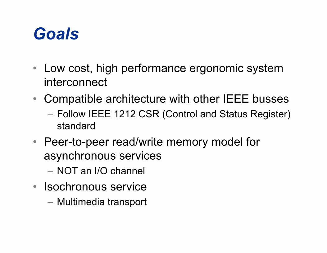
Goals
• Low cost, high performance ergonomic systeminterconnect
• Compatible architecture with other IEEE busses– Follow IEEE 1212 CSR (Control and Status Register)
standard
• Peer-to-peer read/write memory model forasynchronous services– NOT an I/O channel
• Isochronous service– Multimedia transport

Data type Sample size and rate Bit rateISDN 8 kHz x 8 bits 64 Kbit/secCD 44.1 kHz x 16 bits x 2 channels 1.4 Mbit/secDAT 48 kHz x 16 bits x 2 channels 1.5 Mbit/secVideo 25-30 frames/sec 1.5 – 216 Mbit/sec
“Isochronous” ??
• Iso (same) chronous (time) :– Uniform in time
– Having equal duration
– Recurring at regular intervals

Asynch Vs. Isoch
• Asynchronous transport– “Guaranteed delivery”
– Reliability more important than timing
– Retries are OK
• Isochronous transport– “Guaranteed timing”
– Late data is useless
– Never retry

CPUStereo
Interface
DigitalCamera
Printer
SCSI is typical “supervised cabling” — daisy-chain; manual or fixed addresses;terminators at ends; devices with internal terminations must be at one end
Serial Bus is “unsupervised cabling” — “non-cyclic network”; automaticaddress selection, no terminators, locations are arbitrary
Mag Disk Scanner CD ROM CPU
TerminatorTerminator(may be internal)
ID=6 ID=2 ID=3 ID=7
Scanner
Mag Disk
CD ROM
phyphyphy
phy
phyphy phy
Unsupervised!

Data paths (peer-to-peer)
CDROM
DigitalCamera
Scanner Printer
StereoInterface
MagDisk
Live display of video image
Direct printing of scanned image
Digitized sound direct playback
CPU

Clean up the desktop cablemess!
plus telephone/voice, hi-fisound, compressed video
video seri
al
AD
B
modem1394
SCSIvideo floppy modem Net
wo
rk
Ser
ial
Key
bo
ard
So
un
d
Po
wer

1394 family of specifications
IEEE 1212-2001
IEEE 1394-1995,1394a-2000, 1394b-2002
SBP-2,3
1394.1-2004
PC 2001, MacOS platform specs
AV/C general
AV/C disk
IEC 61883 1-6
AV/C taperecorder
content protection, “5C, DTCP”HAVi, UPnP
RBC
IP/1394
Op
en H
CI
HD
MD
DV
D
CD
DV
D8
DV
HS
AV
/C p
anel
AV
/C au
dio
AV
/C tu
ner
DP
P
IIC
1394.3

Key specifications
• IEEE 1394-1995, 1394a-2000, 1394b-2002 High Speed Serial Bus– “Memory-bus-like” logical architecture, isochronous support– Serial implementation of 1212 architecture
• IEEE 1212-2001 CSR Architecture– Standardized addressing, well-defined control and status registers,
configuration declaration, standardized transactions
• “Higher layer” protocols– NCITS.325-1998 SBP-2 integrates DMA into I/O process
• RBC (for mass storage) and IEEE 1394.3 PPDT (for printers)
– IEC 61883 and 1394TA AV/C standards define control and data for A/Vdevices
– RFC 2734 defines Internet Protocol (v4) over 1394• IPv6 and DHCP also as RFCs
– Digital Transport for Content Protection (“5C”/DTCP)– IEEE 1394.1 for bridges, IIC for instrumentation and industrial control,
DPP for consumer cameras/printers, etc.

Some terminology
• “quadlet” - 32-bit word
• “node” - basic addressable device
• “unit” - part of a node, defined by a higherlevel architecture ... examples:– SBP disk drive (X3T10 standard)
– A/V device - VCR, camcorder (IEC 61883standard)

bus #1023(local bus)
bus #1022
bus # 0
bus # 1
node # 0
node # 1
node # 62
•••••
•••••
IEEE 1212
Serial Bus
ROM(1st 1K)
initialunitsspace
2048
256M
1024
512
0
Example:
= all cycle timer registers on local bus
private
node # 63(broadcast)
•••••
initialmemoryspace
register
0x3FF 0x3F 0xFFFFF 0x0000200
IEEE 1212 addressing
• 1394 uses “64-bit fixed” addressing for asynchronoustransactions

Link LayerPacket Transmitter Packet ReceiverCycle Control
Transaction Layer
Physical Layer
Encode/Decode Arbitration Media Interface
Ser
ial B
us
Man
agem
ent
Read, Write, Lock
Packets
Symbols
Electrical Signals& Mechanical Interface
IsochronousChannels
Configuration &Error Control
Hardware
Hardware orFirmware
IEEE 1394 protocol Stack

Cable MediaCable Media
PHY A
Node A
arbitration and resynch
Link Interface
Serial Bus Higher Layers(Link & Transaction)
PHY B
Node B
Cable Interface (port 1)
Cable Interface (port 2)
Cable Interface (port n)
Link Interface
arbitration and resynch
Cable Interface (port n)
Serial BusHigher Layers
Cable interface
• PHY transforms point-to-point cable links into a logicalbus
• Cables and transceivers are bus repeaters

Standard cable media
• CMOS transceiver
– Differential drive, lowvoltage, low current
– DC-coupled for legacy,AC-coupled in new Betamode
1394a 1394b
• 3-pair shielded cable– Two pairs for data transport– One pair for peripheral
power• 2-pair used for most CE
equipment
• Small and rugged connector– Two sockets in the same
area as one mini-DINsocket
• Even smaller for 1394b

6mm(typical)
Power pair:22 AWG /0.87 diameter twisted pair
60% braided shield over foil shield(over signal pairs - 2X)
Signal pairs: (2X)28 AWG/0.87 diameter twisted pairs
97% braided overall shield
0.70 Thick PVC jacket
Fillers for roundness (if required)
Standard cable media example
• Capable of operation at 400 Mbit/sec for 4.5m– Slightly thicker wire allows 10 meter operation
– 1394b encoding allows at least 3.2 Gbit/sec

Standard cable interface features
• Live attach/detach– System protected from power on/off cycling
– Higher layers provide simple management
• Power carried by cable– 30-8 VDC, up to 1.5A per link
• Mac desktops provide 15-25W, PowerBooks 7W
• “SuperHub” reference design provides 90W continous/120W peak
– 1394 TA defined management protocols
– Total available power is system dependent• Node power requirements must be declared in configuration ROM
• Basic source capabilities and sink requirements included in “self-ID”packets at system initialization
• Nodes can either source or sink power
• Multiple power sources on one bus provide additional flexibility

Alternate media
• New media defined in 1394b for long distances– Requires new “beta” mode
• Long distance at S100 can be done via cat 5 UTP– same as 100 Mbit Ethernet– 1394b encoding scrambles data better than 100baseTX, easier
to meet FCC class B emissions limits
• Long distance at S200 and above currently requiresoptical fiber– 50 micron graded index OK for S3200 up to 100m– Plastic optical fibers good for S200 up to 50m
• New technology fibers good for S400 up to 100m, but notmentioned in current draft
– Hard polymer-coated fiber good for S200 up to 100m
• p1394c defines S800 cat 5e operation– 1394 TA is defining S400 UTP for automobiles (30m)
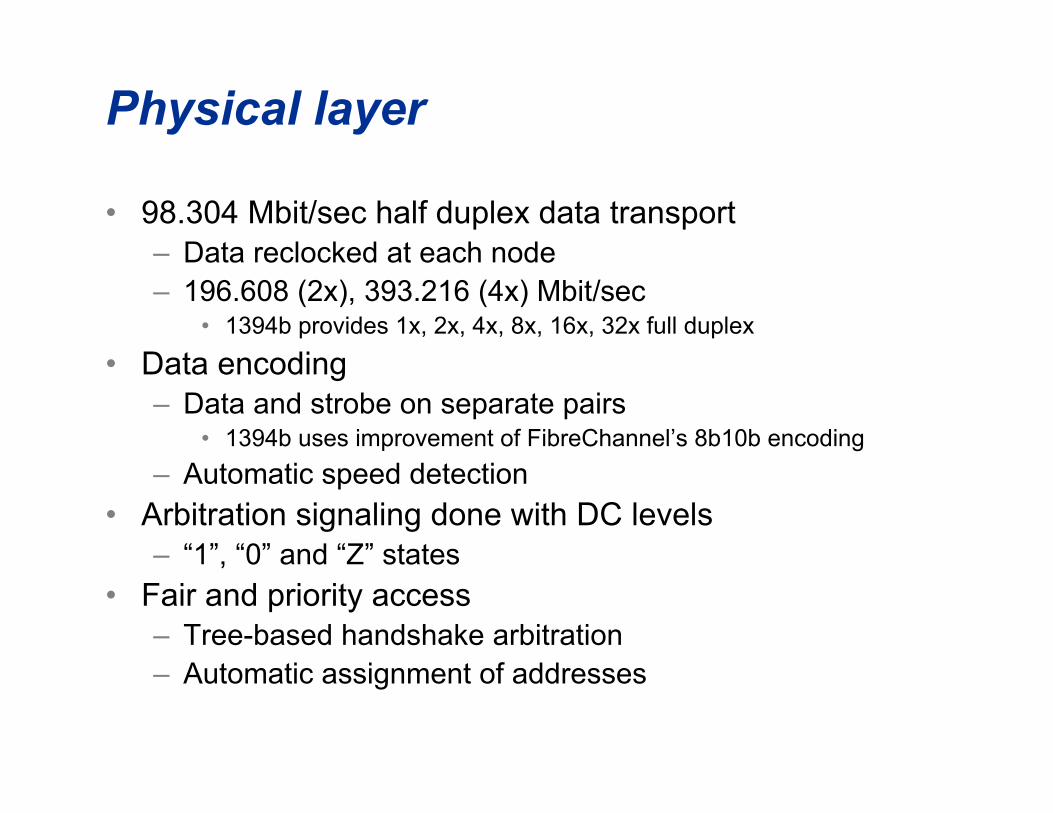
Physical layer
• 98.304 Mbit/sec half duplex data transport– Data reclocked at each node– 196.608 (2x), 393.216 (4x) Mbit/sec
• 1394b provides 1x, 2x, 4x, 8x, 16x, 32x full duplex
• Data encoding– Data and strobe on separate pairs
• 1394b uses improvement of FibreChannel’s 8b10b encoding
– Automatic speed detection
• Arbitration signaling done with DC levels– “1”, “0” and “Z” states
• Fair and priority access– Tree-based handshake arbitration– Automatic assignment of addresses

RxDataRxStrbTxDataTxStrb
resynch
TxArbRxArb
arbitration
localclock
linkinterface
Port 1LogicA B
Port 2LogicA B
Port nLogicA B
Example cable PHY IC
• Two twisted pairs for data:TPA and TPB– For legacy:
• TPA is transmit strobe,receive data
• TPB is receive strobe,transmit data
• Both are bidirectional signalsin arbitration
– For Beta mode:• TPA is receive
• TPB is transmit
• Reclocks repeated packetdata signals using local clock– 1394 is “pleisiochronous”

DataData
StrobeStrobe
1 0 1 1 0 0 0 1
Data Data xor xor StrobeStrobe(delayed)(delayed)
Data-strobe encoding(legacy)
• Either Data or Strobe signal changes in a bitcell, not both– Gives 100% better jitter budget than
conventional clock/data

New “beta” connection model
• High speed PHYs communicate usingcontinuously transmitted dual simplex signalusing 8B10B encoding– Data is first scrambled, then sent to 8B10B encoder
– No repeating data, reduces EM radiation
– Control symbols are not standard IBM 8B10B codes,but have Hamming distance 2 from each other andall data codes
• Little chance of data error confusing protocols
• Also scrambled by same mechanism
• Definitely cool technology, Alistair Coles of HP

These three phases typically complete in
less than 10 µsec
Cable arbitration phases
• Reset– Forced whenever node is attached or removed
• Tree Identification– Transforms a non-cyclic topology into a tree with a “root” node
at its head– 1394b beta connections can be broken, allows arbitrary
topology at reset
• Self Identification– Assigns physical node number (Node ID), exchange speed
capabilities with neighbors, broadcast basic capabilities
• Normal Arbitration– Requests sent towards root in 1394-1995 and 1394a (requests
and data cannot overlap)– Sent towards currently transmitting node in 1394b beta mode
(requests can overlap data)

leaf(branch
for 1394b)
branch
branch
leaf(branch
for 1394b)leaf
1394b allowsloops
Tree identification #1
• After reset, each node only knows if it is a leaf (one connectedport) or a branch (more than one connected port)

leaf
root
branch
leaf leaf
ch ch
ch ch
p
pp
p
1394b breaksloops in tree ID
Tree identification #2
• After Tree ID process, the Root node is determined and each port islabeled as pointing to a child or a parent
– Root assignment is “sticky”, will normally persist across a bus reset.– 1394b breaks any loops on beta connections even before Tree ID starts
node #0
rootnode #4
node #3
node #1 node #2
ch ch
ch ch
p
pp
p
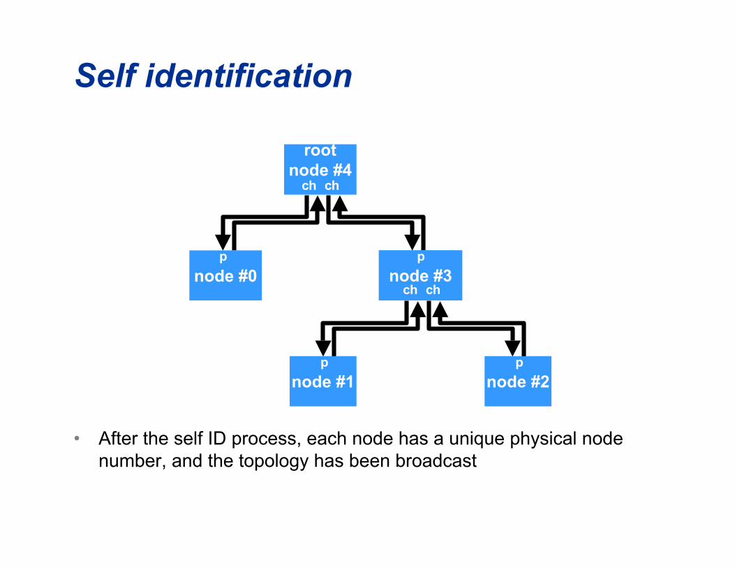
Self identification
• After the self ID process, each node has a unique physical nodenumber, and the topology has been broadcast

Legacy arbitration #1
• Suppose nodes #0 and #2 start to arbitrate at thesame time, they both send a request to their parent ...
request
request
node #0
rootnode #4
node #3
node #1 node #2
ch ch
ch ch
p
pp
p

Legacy arbitration #2
• The parents forward the request to their parent anddeny access to their other children ...
request
request
request
deny
deny
node #0
rootnode #4
node #3
node #1 node #2
ch ch
ch ch
p
pp
p

Legacy arbitration #3
• The root grants access to the first request (#0), and the otherparent withdraws it's request and passes on the deny ...
request
request deny
deny
grant
deny
node #0
rootnode #4
node #3
node #1 node #2
ch ch
ch ch
p
pp
p

Legacy arbitration #4
• The winning node #0 changes its request to a data transfer prefix,while the loosing node #2 withdraws its request ...
data prefix deny
deny
grant
deny
node #0
rootnode #4
node #3
node #1 node #2
ch ch
ch ch
p
pp
p

Legacy arbitration #5
• The parent of node 1 sees the data prefix and withdraws thegrant, and now all nodes are correctly oriented to repeat thepacket data (a "deny" is a "data prefix!) ...
data prefix data prefix
data prefix
data prefix
node #0
rootnode #4
node #3
node #1 node #2
ch ch
ch ch
p
pp
p

Beta arbitration
• Dual simplex connections means that arbitration isoverlapped with data transmission!
Requests go inopposite direction
as data
Last node to sendin a subaction is
the “boss”
node #0BOSS
rootnode #4
node #3
node #1 node #2
ch ch
ch ch
p
pp
p
data data
data
data
request
request
request request

Beta arbitration concepts
• General rule: send requests continually, and in everydirection that is not carrying packet information– Send highest priority request from all ports and attached PHY
• Node sending data is the “BOSS”– If BOSS knows that data being sent is the end of a subaction, it
can issue a grant to the highest priority request• Examples: sending an ACK, sending a broadcast packet ...
• Many fallback methods, error recovery straight-forward– More cool technology, David LaFollette of Intel, Jerry Hauck and
Michael Johas Teener of Zayante

Beta and Legacy interoperation
• “Bilingual” modes specified for “border” PHYs– A border PHY is one that has at least one port
operating in legacy (“DS” encoded) mode and oneport operating in beta mode
– Ports can be either “legacy” (DS-only), “beta”, or“bilingual”
• Bilingual ports support both beta and legacy connections
• Beta-only PHYs are quite simple!– Border PHYs somewhat more difficult, but just more
logic
– Bilingual ports have difficult analog designs

Link layer
• Implements acknowledged datagram service– Called a "subaction" of arbitration, packet
transmission, and acknowledge
• Isochronous access provides multiple"channels" each 125 µsec "cycle" period– Channels are broadcast packets to one of 64 channel
addresses
– Channel count limited by available bandwidth• Channel numbers and bandwidth managed by higher layers

Link layer operation
RequesterRequesterLink layerLink layer
ResponderResponderLink layerLink layer
Link requestLink request
Link indicationLink indication
LinkLinkconfirmationconfirmation
Link responseLink response
arbitration &arbitration &packetpacket
transmissiontransmission
acknowledgeacknowledge(not present for(not present for
broadcast orbroadcast orisochronous)isochronous)
entire h
eader
ackarb
48 3232 acknowledgegap
≥ 1 µsec
16
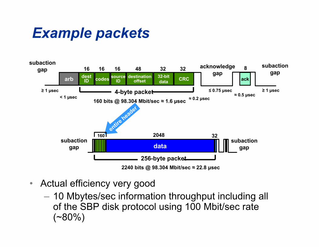
160 bits @ 98.304 Mbit/sec ≈ 1.6 µsec
subactiongap
< 1 µsec
2240 bits @ 98.304 Mbit/sec ≈ 22.8 µsec
160 2048
16
256-byte packet
4-byte packet ≥ 1 µsec≤ 0.75 µsec
≈ 0.2 µsec≈ 0.5 µsec
16destID codes source
IDdestination
offset32-bitdata
CRC
subactiongap
subactiongap
subactiongap data
32
8
Example packets
• Actual efficiency very good– 10 Mbytes/sec information throughput including all
of the SBP disk protocol using 100 Mbit/sec rate(~80%)
owner A
subaction gapsarbitrationreset gap
arbitration reset gap
subaction
owner B owner M
dataarbackdataarbdata • • •
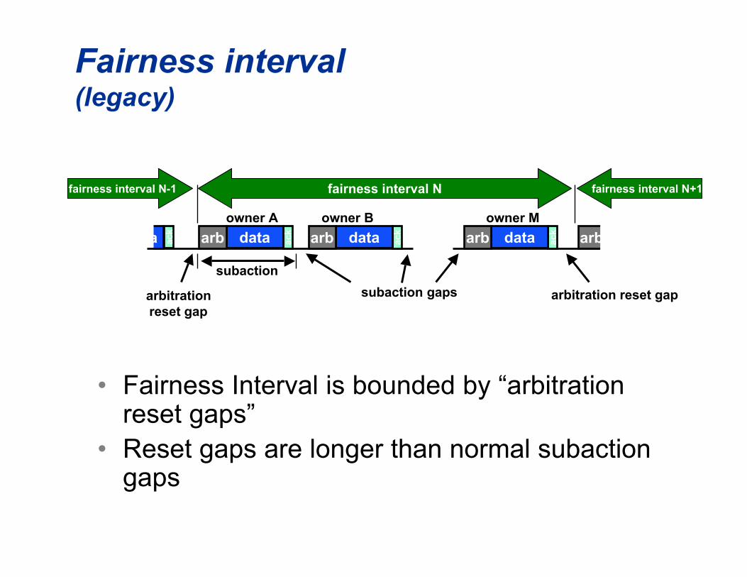
Fairness interval(legacy)
• Fairness Interval is bounded by “arbitrationreset gaps”
• Reset gaps are longer than normal subactiongaps
fairness interval Nfairness interval N-1 fairness interval N+1
ack
ackdataarb ackdataarb

set at arbitration reset gap cleared when node wins arbitration
node A
fairnessinterval N-1
arb
node A
arb
itra
tio
n_e
nab
le f
lag
node B
node C
node Barb node Carb
fairnessinterval N+1
arb
itra
tio
n r
eset
gap
arb
itra
tio
n r
eset
gap
Fair arbitration (legacy)
• Each node gets one access opportunity each fairnessinterval– special case for isochronous data
fairness interval N

ack
owner A
arbitrationreset token
arbitrationreset token
subaction
owner B owner M
ackdataackdataackdata • • •
Fairness interval(Beta)
• Fairness Interval is bounded by “arbitration resettokens”
• Arbitration reset tokens are labeled “ODD” or “EVEN”,as are the fairness intervals– Allows pipelining of arbitration for the next fairness interval
fairness interval N (even)fairness intervalN-1 (odd)
fairness intervalN+1 (odd)
even
ackdata datao
dd

none_odd
next_odd
none_odd
current
data
none_evendatanone_odd
node A
even
node B
Tra
nsm
itte
dre
qu
est
(or
dat
a)
node C
node A
node B node C
Fair arbitration (Beta)
od
d
current
datanext_odd
node A node B
none_odddatanext_even
data next_odd
… while nodes B & Cstart requesting
bus here
data/tokenxmit at BOSS
node A wants to sendanother packet, sosends “next_odd”
request
requestreceive at
BOSS
next_even current
Node C is BOSS, and is only seeing “next_odd”or “idle_even”, so sends arb_reset_odd
node X
node A has a request from theprevious fairness interval,
pipelined requests are highest
od
d

Cycle structure (legacy)
• The cycle start is sent by the cycle master, which must be theroot node
ch J
cycle #mcycle #m-1
cycle startdata = y
cycle startdata = x
ch J ch k ch Npacket
Cpacket
Apacket
B
isochronous(short) gaps
asynchronous(long) gaps
cycle synchcycle synch
cycle #mstart delay = x
cycle #m+1start delay = y
nominal cycle period = 125 µsec ± 100 PPM
• • •
cycle #m+1

ch J
cycle #mcycle #m-1
cycle startdata = y
cycle startdata = x
ch J ch k ch Npacket
Cpacket
Apacket
B
cycle synchcycle synch
cycle #mstart delay = x
cycle #m+1start delay = y
nominal cycle period = 125 µsec ± 100 PPM
• • •
cycle #m+1C
S e
ven
CS
od
d
asyn
ch
Asynchronous start token(no isoch requests of
current phase)
Cycle starteven token
Cycle startodd token
• • •
Cycle structure (Beta)
• Cycle start phase has NO correlation with the cyclenumber– Odd/even just used for request pipelining
Attributes of 1394 isochronousservice
• Instantaneous jitter for packet delivery is about200 µs worst case– Most applications provide about 250 µsec buffers
• Long term drift is determined by cycle master– 100 ppm clock accuracy required
– Better specifications coming from digital studiostudies

Requestor Requestor Transaction Transaction
LayerLayerTransaction Transaction
RequestRequest
Transaction Transaction ConfirmationConfirmation
Transaction Transaction IndicationIndication
Transaction Transaction ResponseResponse
transaction control
transaction control informationinformation
includes data if includes data if "write" or "lock""write" or "lock"
transaction status
transaction status
informationinformation
includes data if includes data if "read" or "lock""read" or "lock"
Responder Responder Transaction Transaction
LayerLayer
Transaction layer

Multiple transaction types
• Simplified 4-byte (quadlet) read and write arerequired
• Variable-length block read and write areoptional
• Lock transactions optional– Swap, Compare-and-swap needed for bus
management

Efficient media usage
• Split transactions required– Transactions have request and response parts
– Bus is never busy unless data is actually beingtransferred
• Request and response can be unified twoways– "Read" and "Lock" can have concatenated
subactions
– "Write" can have immediate completion

Other Link-Layer operations cantake place between these two
subactions, including sendingother transaction requests or
responses
LinkRequest
RequestPacket
TransactionLayer
LinkIndication
ReadReadRequestRequest
LinkLayer
RequesterLink
LayerTransaction
Layer
Responder
ReadReadIndicationIndication
Resp(pend)Ack
(pend)
Conf(pend)
LinkRequestResp
PacketLinkIndication
Resp(compl) Ack
(compl)
Conf(compl)
ReadReadResponseResponse(complete,(complete,with data)with data)
Read ConfirmationRead Confirmation(complete, with data)(complete, with data)
Split transaction
• Request andresponse haveseparatesubactions

LinkRequest
Request
Packet
TransactionLayer
LinkIndication
ReadRequest
LinkLayer
RequesterLink
LayerTransaction
Layer
Responder
ReadIndication
Resp(pend)Ack
(pend)
Conf(pend)
LinkRequestResp
PacketLinkIndication
Resp(compl) Ack
(compl)
Conf(compl)
ReadResponse(complete,with data)
ReadConfirmation(complete, with
data)
the responder does not releasethe bus after sending the ack,sends response packet within1.5µsec
Concatenated transaction
• Used if responderis fast enough toreturn data beforeack is completed
LinkReq
ReqPacket
TransactionLayer
LinkInd
Write Request
LinkLayer
RequesterLink
LayerTransaction
Layer
Responder
Write Indication
Resp(comp)Ack
(comp)
Conf(comp)
Write Response(complete)
Write Confirmation(complete)
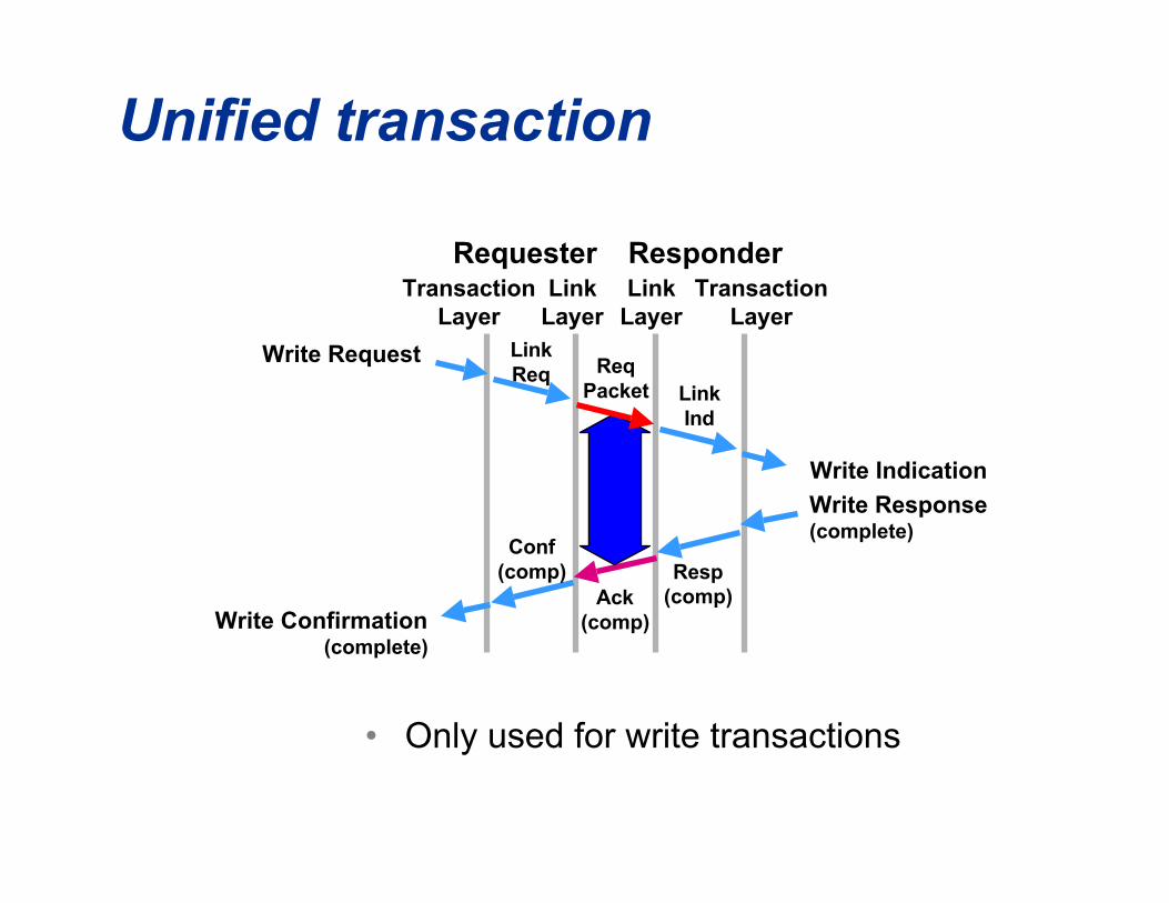
Unified transaction
• Only used for write transactions

Bus management
• Automatic address assignment– Done in physical layer with self-ID process
– Root (cycle master) is “sticky” between bus resets
• Resource management– Isochronous channels and bandwidth (also “sticky” ...
stay allocated between bus resets).
– Power
• Standardized addresses and configuration ROMfrom IEEE 1212 architecture
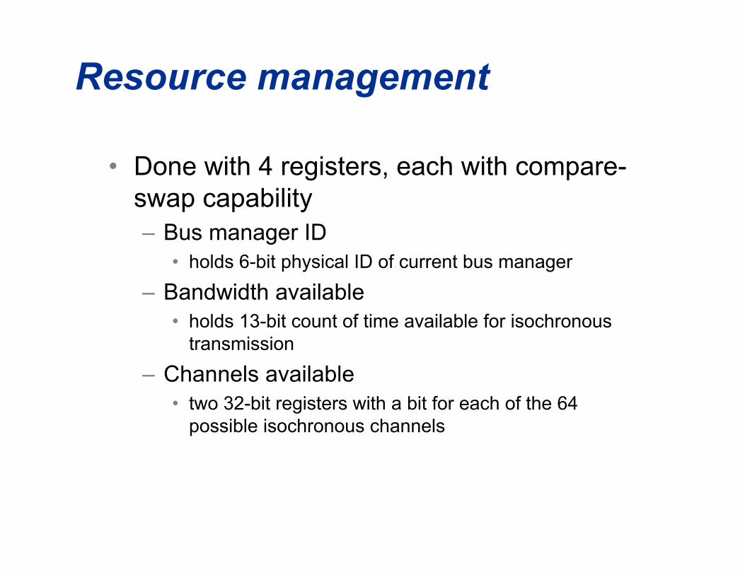
Resource management
• Done with 4 registers, each with compare-swap capability– Bus manager ID
• holds 6-bit physical ID of current bus manager
– Bandwidth available• holds 13-bit count of time available for isochronous
transmission
– Channels available• two 32-bit registers with a bit for each of the 64
possible isochronous channels

Compare-swap operation:
• request has “new data” and “compare” values
• responder compares current value (“old data”)at requested address with “compare” value
• if equal, the data at the address is replaced with“new data” value
• in all cases, “old data” is returned to requester

• Example: allocate bandwidthtest_bw = read4 (addr = bandwidth_available);old_bw = test_bw + 1; // force entry into loop 1st timewhile (old_bw != test_bw) {
old_bw = test_bw;new_bw = old_bw - bandwidth_needed;if (new_bw < 0) fail; // all out of bandwidthtest_bw = compare_swap (addr = bandwidth_available,new_data = new_bw, compare = old_bw); }
• test_bw will be equal to old_bw if no other node hasaltered the bandwidth_available register between the timeit was read and the time of the compare_swap
Using compare-swap

Where are the bus resourceregisters?
• On bus reset PHY builds network, assignsaddresses, sends self-ID packets– power requirements/capabilities, maximum speed
rating, port status (child, parent, unconnected)
– “contender” or not
– link (higher layers) running or not
• Highest numbered node with both contenderand link-on bit is “isochronous resourcemanager”– this is the node that has the four resource manager
registers
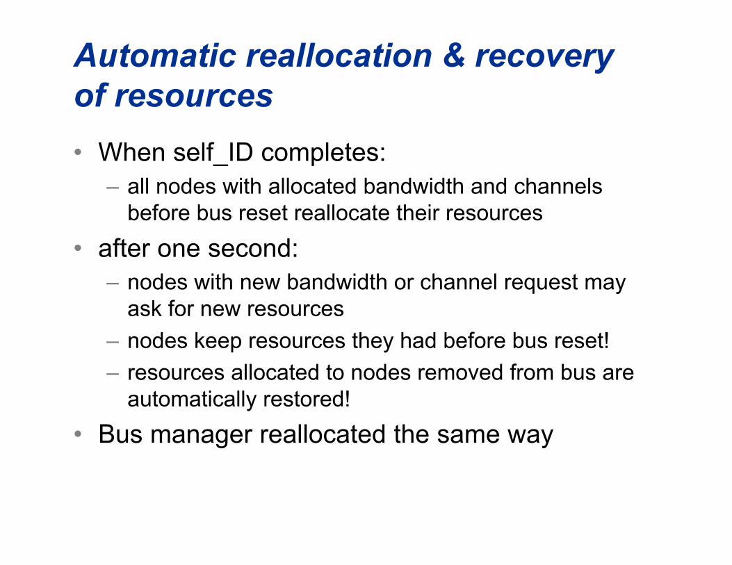
Automatic reallocation & recoveryof resources
• When self_ID completes:– all nodes with allocated bandwidth and channels
before bus reset reallocate their resources
• after one second:– nodes with new bandwidth or channel request may
ask for new resources
– nodes keep resources they had before bus reset!
– resources allocated to nodes removed from bus areautomatically restored!
• Bus manager reallocated the same way

Automatic restart of isochronousoperation
• Root assignment is persistent across bus reset– Cycle master operation restarts after bus reset if
node is still root (normal case)
• Nodes assume that bandwidth and channelallocations are still good– Automatically restart sending when receive cycle
start
• Only fails if two operating subnets are joined– If reallocation fails, node terminates sending– If bus over allocated, cycle master detects isoch data
sent for longer than 100 µsec and stops sendingcycle starts

How does 1394 help?
• Much better human interface– smaller, more rugged connectors with defined usage
– Hot plugging, no manual configuration
• Excellent real performance– High true data rates
– Direct map to processor I/O model
– DMA is simple: CPU memory directly available toperipherals
• example: SBP supports direct scatter/gather buffers

... but even more important
• Direct support for isochronous data– THE current choice for digital consumer
video, high-end audio

Getting documentation
• “IEEE 1394-1995 High Performance Serial Bus”,“IEEE 1394a-2000 Amendment 1”, “IEEE 1394b-2002 Amendment 2”– IEEE Standards Office +1-908-981-1393,
http://standards.ieee.org
• Internet email reflectors– “[email protected]”, subscription information at
http://grouper.ieee.org/groups/1394/c
• 1394 Trade Association - http://www.1394ta.org

Thank You