technical info package sgt-8000h · gas turbine . the sgt-8000h is a single shaft gas turbine of...
TRANSCRIPT

SeaFloat SCC-8000H
Technical Solution Information
www.siemens.com/seafloat

Technical Information Package SCC-8000H | SeaFloat | October 2018 I Version 1 ©2018, Siemens Power and Gas Solutions 2
Key benefits
• High efficiency (up to 41% SC, >61% CC)
• Fast start-up capability, high operational flexibility
• Low lifecycle costs
• High reliability and availability
• High serviceability
• Reduced emissions per kWh
• High efficiency and low emission also in part-load operation
Outstanding performance available in SeaFloat application
SGT-8000H based combined cycle power plant in multi shaft arrangement has been optimized for SeaFloat application, i.e. it can be installed on floating devices such as barges or platforms. The design is based on Siemens' proven land-based reference power plant, which is known to provide reliable electricity at high efficiency and low cost. The SeaFloat adaption of the SGT-8000H is designed to withstand typical maritime conditions such motions (roll & pitch, accelerations), hull deflections and environmental conditions such as spray water. SCC-8000H SeaFloat multi shaft plants can be arranged in 1+1 arrangement i.e. one (1) gas turbine, one (1) HRSG routed to one (1) steam turbine, as well as in a 2+1 arrangement which consists of two (2) gas turbines and two (2) HRSGs routed to one (1) steam turbine.
If desired open cycle installation can be provided as well. With the SCC-8000H SeaFloat power plant the well-known and proven H-class benefits have now been complemented with all the benefits of a mobile, floating power plant. The SCC-8000H based SeaFloat combined cycle power plant provides an optimum balance between capital cost, plant performance as well as operation and maintenance benefits.

Technical Information Package SCC-8000H | SeaFloat | October 2018 I Version 1 ©2018, Siemens Power and Gas Solutions 3
Architectural impression

Technical Information Package SCC-8000H | SeaFloat | October 2018 I Version 1 ©2018, Siemens Power and Gas Solutions 4
Infographic

Technical Information Package SCC-8000H | SeaFloat | October 2018 I Version 1 ©2018, Siemens Power and Gas Solutions 5
Figure: Typical Single-lift Package with SGT-800
SeaFloat brief description Scope of supply and services In the scope of supply for main components of the power plant SCC-8000H in 1+1 configuration comprises the following major equipment:
• Gas turbine SGT-8000H along with the GT generators SGen-2000P
• Steam turbine SST-5000 along with the ST air-cooled generators SGen-100A
• Condenser SCon-4000
• Heat recovery steam generator (HRSG): Drum type, triple pressure with reheat
• Power control center for Siemens supplied items (incl. UPS, battery, LV Switchgear)
• Plant control systems (SPPA-T3000)
• Sampling and Chemical Dosing Skid
• Components for gas handling (incl. gas flowmeter, gas-chromatograph, gas-preheater)
• Main pumps (feedwater pumps, condensate extraction pump, condensate recirculation pumps)
• Erection and commissioning Service (ECS) for Siemens supplied items (as a separate contract)
All remaining scope of supply is within the obligation of the ship yard or third party which closely aligns with Siemens AG to ensure a state of the art and reliable power plant.
1x 1+1 SCC5-8000H = 170m x 56m (length x width)

Technical Information Package SCC-8000H | SeaFloat | October 2018 I Version 1 ©2018, Siemens Power and Gas Solutions 6
Brief description of the main components Pre-designed single lift packages will be installed at highly qualified shipyards. These single lift packages are available for the gas turbine/ generator set, for the steam turbine/ generator set and for several BoP skids. The high grade of pre-fabrication of Siemens in-house HRSG contributes to the quick installation on the barge. As far as possible commissioning of the systems, inclusive HRSG cleaning, is done at the shipyard, thus the hock up and hot commissioning at final destination is limited to minimum effort. Gas Turbine
The SGT-8000H is a single shaft gas turbine of single casing design with high efficiency, low fuel consumption and low emissions in combination with high availability and reliability, service-oriented design and long inspection intervals. Following a long history of successful Siemens gas turbine development, the SGT-8000H provides the following advanced design features:
- 16 can annular combustors based Platform Combustion System (PCS) - Axial 13 stage compressor with high mass flow and four rows of
variable guide vanes for improved turndown - Four stage turbine, stage 1 to 3 with improved TBC coated blades and
vanes, proven casting materials and air-cooled - Disc-type rotor with central tie bolt and radial serrations - Two journal bearings and one thrust bearing - Generator drive at compressor intake end - Axial exhaust diffuser
The rotor is supported by two journal bearings and one thrust bearing. The combined journal and thrust bearing is located at the compressor end and the second journal bearing at the exhaust end of the turbine. The rotor is an assembly of blade carrying disks, and hollow shaft sections, held together by a pre-stressed central tie bolt. Hirth serration ensures the alignment of disks and hollow shaft sections at the same time allowing free radial expansion and contraction. The turbine rotor is air-cooled internally.
The combustion system consists of 16 baskets with air cooled transitions. The annular arrangement provides a remarkable uniformity of the exhaust gas temperature field over the full cross-sectional area of the turbine inlet, thus eliminating hot and cold spots. The ultra-low NOx technology reduces the suppresses formation of thermal NOx without injection of steam or water. This combustion system combines all the advantages of optimal combustion, including
- Low NOx and CO emissions - Low pressure drop - High operating flexibility - Optimal size and number of burners - Compact design with easy accessibility.
Generator for Gas Turbine
The two-pole SGen-2000P generator uses a directly water-cooled stator winding and a radially direct air-cooled rotor winding. The air coolers are arranged at the bottom of the base frame, divided into three sections. The three-phase winding inserted in the stator core slots is of two-layer transposed-bar design. The winding is vacuum pressure impregnated together with the stator core. The high-voltage insulation is provided according to the proven MICALASTIC system. The generator rotor shaft is a vacuum-cast forging and is supported in two babbitt-lined journal pedestal bearings. At each end of the generator a shaft-mounted low-pressure single-stage compressor circulates of the pressurized cooling air. Cold- and warm gas temperatures are monitored in the relevant areas. The air gauge pressure is controlled in relation to the actual loading to optimize the part load efficiency. The stator winding bars contain stainless steel cooling ducts. Demineralized cooling water flows through these ducts and dissipates the heat from the stator winding. The water flows from the inlet manifold into the stator bar ends of the top stator bar through TeflonTM insulated hoses. When being discharged from the bars at the other end, the water is redirected into the bottom bar, collected by hoses and a discharge manifold and is returned to the skid mounted water tank. An excitation transformer is used to take the excitation current from the auxiliary power system. A start-up frequency converter is provided for start-

Technical Information Package SCC-8000H | SeaFloat | October 2018 I Version 1 ©2018, Siemens Power and Gas Solutions 7
up of the turbine generator unit. The generator acts as a motor in the converter mode to start the gas turbine set without additional rotating prime mover. The converter forms part of the static excitation equipment. Features of the generator:
- highest efficiency - proven epoxy-mica insulation system of stator winding - low maintenance costs.
Steam Turbine Plant
HP/IP Turbine
With the compact design of the combined HP/IP turbine hot steam conditions are confined to the middle of the casing, while the steam glands at the casing ends are in regions of relatively low steam conditions. Temperature decay is much slower when compared to the design with individual turbine casings. Consequently, the start-up times are significantly shorter. This compact design perfectly fits to the SeaFloat application which aims to decrease the footprint of the entire plant as much as possible. LP Turbine
The main feature of the LP turbine is the double shell inner casing, which can be displaced axially by means of pushrods. The differential expansion between rotor and casings is thus minimized under all operating conditions. This is essential for high efficiency.
Condensing Plant
The condenser is a box-type surface condenser. The steam space is of a rectangular cross-section in order to achieve optimum utilization of the enclosed volume for the necessary condensing surface. The condenser is located below the LP turbine and forms an integral part of it. The steam dome, shell, hotwell, and the water boxes are steel fabrications. The condenser is fixed to the foundation beneath. Thermal expansion will be accommodated by means of Teflon pads. The double-flow LP turbine outer casing is connected to the condenser via the steam dome. The steam dome is welded to the exhaust casing of the turbine with the result that the LP turbine cylinder and the condenser form one unit. Final design of the condenser and the connection type to the LP section of the Steam turbine depends on the Siemens internal engineering activities. Baffle plates in the water boxes prevent sloshing of water due to movement of the barge. Generator for Steam Turbine
The generator is of two-pole type, with direct radial air rotor cooling and indirect air cooling for the stator winding. These generators use either brushless excitation with a stationary field exciter and rotating bridge-connected rectifier or static excitation, whereby the excitation power is taken from static excitation equipment and supplied to the rotor winding via the brush gear, carbon brushes and slip rings. The standard design is IM 7215 according to IEC 60034-7 and features pedestal type sleeve bearings.
Technical Information Package SCC-8000H | SeaFloat | October 2018 I Version 1 ©2018, Siemens Power and Gas Solutions 8
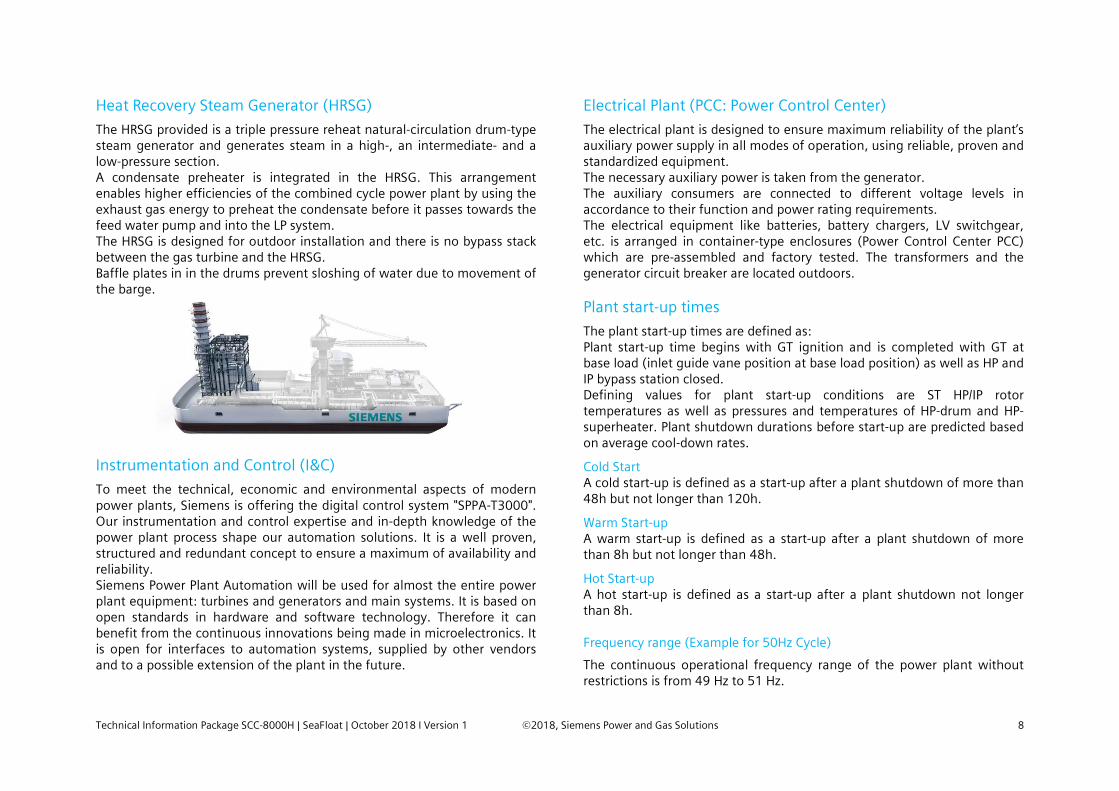
Heat Recovery Steam Generator (HRSG)
The HRSG provided is a triple pressure reheat natural-circulation drum-type steam generator and generates steam in a high-, an intermediate- and a low-pressure section. A condensate preheater is integrated in the HRSG. This arrangement enables higher efficiencies of the combined cycle power plant by using the exhaust gas energy to preheat the condensate before it passes towards the feed water pump and into the LP system. The HRSG is designed for outdoor installation and there is no bypass stack between the gas turbine and the HRSG. Baffle plates in in the drums prevent sloshing of water due to movement of the barge.
Instrumentation and Control (I&C)
To meet the technical, economic and environmental aspects of modern power plants, Siemens is offering the digital control system "SPPA-T3000". Our instrumentation and control expertise and in-depth knowledge of the power plant process shape our automation solutions. It is a well proven, structured and redundant concept to ensure a maximum of availability and reliability. Siemens Power Plant Automation will be used for almost the entire power plant equipment: turbines and generators and main systems. It is based on open standards in hardware and software technology. Therefore it can benefit from the continuous innovations being made in microelectronics. It is open for interfaces to automation systems, supplied by other vendors and to a possible extension of the plant in the future.
Electrical Plant (PCC: Power Control Center)
The electrical plant is designed to ensure maximum reliability of the plant’s auxiliary power supply in all modes of operation, using reliable, proven and standardized equipment. The necessary auxiliary power is taken from the generator. The auxiliary consumers are connected to different voltage levels in accordance to their function and power rating requirements. The electrical equipment like batteries, battery chargers, LV switchgear, etc. is arranged in container-type enclosures (Power Control Center PCC) which are pre-assembled and factory tested. The transformers and the generator circuit breaker are located outdoors. Plant start-up times
The plant start-up times are defined as: Plant start-up time begins with GT ignition and is completed with GT at base load (inlet guide vane position at base load position) as well as HP and IP bypass station closed. Defining values for plant start-up conditions are ST HP/IP rotor temperatures as well as pressures and temperatures of HP-drum and HP-superheater. Plant shutdown durations before start-up are predicted based on average cool-down rates.
Cold Start A cold start-up is defined as a start-up after a plant shutdown of more than 48h but not longer than 120h.
Warm Start-up A warm start-up is defined as a start-up after a plant shutdown of more than 8h but not longer than 48h.
Hot Start-up A hot start-up is defined as a start-up after a plant shutdown not longer than 8h. Frequency range (Example for 50Hz Cycle)
The continuous operational frequency range of the power plant without restrictions is from 49 Hz to 51 Hz.

Technical Information Package SCC-8000H | SeaFloat | October 2018 I Version 1 ©2018, Siemens Power and Gas Solutions 9
Operation in the frequency ranges from 47 Hz to 49 Hz and from 51 Hz to 52 Hz is limited to 30 seconds per event. After this time span the protection system will disconnect the power plant from the grid. The accumulated operation time in these frequency ranges is limited to 30 minutes in total. After 30 minutes an inspection is recommended. At 47,0 Hz and at 52,0 Hz power plant disconnection is initiated without time delay. Fulfilment of Grid Code Requirements
Primary Frequency Control is achieved by increase or decrease of the gas turbine output. Primary Frequency Control is available in the IGV range of the Gas Turbine. The load dynamics during Primary Frequency Control depends on the project specific requirements. The maximum value is up to 3%/s of the GT nominal output. The droop setting is adjustable at the GT speed controller. Typical droop setting values are in the range from 3 % to 8 %. Secondary Frequency Control is achieved by load setpoint adjustment by the load dispatch center, provided that the plant is operated in part load accordingly. Motion Detection on GT, ST and HRSG
As the power plant is built on a barge/ship the movement of the barge/ship is monitored by Motion Detectors (Acceleration & Angles). Following directions will be monitored:
- x = surge/longitudinal - y = sway/transversal - z = heave/vertical
If the plant is in operation and the GT, ST or HRSG exceeds the allowed level of acceleration, the equipment will be tripped. Consideration of marine conditions
While the SCC-8000H based SeaFloat power plant builds up respectively uses well proven equipment from Siemens’ vast experience in land based combined power plants, the marine conditions, mainly movements, acceleration and hull deflection have been addressed by the following main measures
- 3- or multiple supports with vibration de-coupling of rotating equipment
- Stiffening of steel structures and frames (e.g. in HRSG) - Flexible elements and interfaces - Optimization of bearings of rotating equipment - Baffle plates e.g. in lube oil reservoirs, boiler drums and condenser to
avoid sloshing
Main features and performance information
SGT-8000H based SeaFloat power plants provide highest floating combined cycle plant efficiency, even at part load operation. Dry low-NOx single or dual fuel burners ensure low NOx and CO emissions.
- High GT reliability of 99.5% - High CC availability - Highest efficiency, refer to below table - Dry Low Emissions (DLE) - Low water consumption for steam cycle make up, no condensate
polishing plant on board
Simple cycle power generation 1xSS 50Hz 1xSS 60Hz
Power output 450 MW 310 MW
Gross efficiency > 41 % > 40 %

Technical Information Package SCC-8000H | SeaFloat | October 2018 I Version 1 ©2018, Siemens Power and Gas Solutions 10
Combined cycle power generation
1x1 50Hz 2x1 50Hz 1x1 60Hz 2x1 60Hz
Net plant power output 665 MW 1,330 MW 460 MW 930 MW
Net plant efficiency 61% 61% 61% 61%
Number of gas turbines 1 2 1 2
Steam turbine model SST-5000 SST-5000 SST-5000 SST-5000
Note:
Emissions, NOx, [ppmV] <25 @ 15% O2 (50-100% GT load)
Emissions, CO, [ppmV] <10 @ 15% O2 (50-100% GT load)
Installed performance at ISO conditions
List of Attachments Attachment 1 Plant Layout Drawing 1x1 - Top View
Attachment 2 Plant Layout Drawing 1x1 – Section Views
Attachment 3 Plant Layout Drawing 1x1 – Plan View with Service Area
Attachment 4 Plant Layout Drawing 2x1 - Top View
Attachment 5 Plant Layout Drawing 2x1 – Section Views
Attachment 6 G-Plan – Water Balance
Attachment 7 I&C Overview
Attachment 8 Single Line Diagram
Attachment 9 L-Plan – Process Flow Diagram
For information only. Not guaranteed. Actual results are dependent on-site specifics. Subject to changes and provided on an “as is” basis without any express or implied representation or warranty of any kind and without any verification as to accuracy, suitability or completeness; terms subject to a final contract between the parties. Actual benefits and results are dependent on a variety of factors such as plant specification, site specifics, operational profile and local market conditions.