technical iec report tr 61131-4 - amobbsd1.amobbs.com/bbs_upload782111/files_31/ourdev_569654.pdf......
TRANSCRIPT
TECHNICAL REPORT
IEC TR 61131-4
Second edition2004-07
Programmable controllers –
Part 4: User guidelines
Reference number IEC/TR 61131-4:2004(E)
Copyright International Electrotechnical Commission Provided by IHS under license with IEC
Not for ResaleNo reproduction or networking permitted without license from IHS
--``````-`-`,,`,,`,`,,`---
Publication numbering
As from 1 January 1997 all IEC publications are issued with a designation in the 60000 series. For example, IEC 34-1 is now referred to as IEC 60034-1.
Consolidated editions
The IEC is now publishing consolidated versions of its publications. For example, edition numbers 1.0, 1.1 and 1.2 refer, respectively, to the base publication, the base publication incorporating amendment 1 and the base publication incorporating amendments 1 and 2.
Further information on IEC publications
The technical content of IEC publications is kept under constant review by the IEC, thus ensuring that the content reflects current technology. Information relating to this publication, including its validity, is available in the IEC Catalogue of publications (see below) in addition to new editions, amendments and corrigenda. Information on the subjects under consideration and work in progress undertaken by the technical committee which has prepared this publication, as well as the list of publications issued, is also available from the following:
• IEC Web Site (www.iec.ch)
• Catalogue of IEC publications
The on-line catalogue on the IEC web site (www.iec.ch/searchpub) enables you to search by a variety of criteria including text searches, technical committees and date of publication. On-line information is also available on recently issued publications, withdrawn and replaced publications, as well as corrigenda.
• IEC Just Published
This summary of recently issued publications (www.iec.ch/online_news/ justpub) is also available by email. Please contact the Customer Service Centre (see below) for further information.
• Customer Service Centre
If you have any questions regarding this publication or need further assistance, please contact the Customer Service Centre:
Email: [email protected] Tel: +41 22 919 02 11 Fax: +41 22 919 03 00
Copyright International Electrotechnical Commission Provided by IHS under license with IEC
Not for ResaleNo reproduction or networking permitted without license from IHS
--``````-`-`,,`,,`,`,,`---
TECHNICAL REPORT
IECTR 61131-4
Second edition2004-07
Programmable controllers –
Part 4: User guidelines
PRICE CODE
IEC 2004 Copyright - all rights reserved
No part of this publication may be reproduced or utilized in any form or by any means, electronic or mechanical, including photocopying and microfilm, without permission in writing from the publisher.
International Electrotechnical Commission, 3, rue de Varembé, PO Box 131, CH-1211 Geneva 20, SwitzerlandTelephone: +41 22 919 02 11 Telefax: +41 22 919 03 00 E-mail: [email protected] Web: www.iec.ch
XF
For price, see current catalogue
Commission Electrotechnique InternationaleInternational Electrotechnical CommissionМеждународная Электротехническая Комиссия
Copyright International Electrotechnical Commission Provided by IHS under license with IEC
Not for ResaleNo reproduction or networking permitted without license from IHS
--``````-`-`,,`,,`,`,,`---
– 2 – TR 61131-4 IEC:2004(E)
CONTENTS
FOREWORD...........................................................................................................................5 INTRODUCTION.....................................................................................................................7 1 General ............................................................................................................................8
1.1 Scope and object.....................................................................................................8 1.2 Normative references ..............................................................................................9 1.3 Use of this report.....................................................................................................9
2 Terms and definitions ..................................................................................................... 10 3 General recommendations for installation ....................................................................... 11
3.1 Environmental conditions ...................................................................................... 11 3.2 Field wiring............................................................................................................ 11 3.3 Electromagnetic compatibility ................................................................................ 12 3.4 User system markings ........................................................................................... 13
4 PLC in functional safety applications .............................................................................. 13 4.1 Functional safety and safety-related-system concept............................................. 13 4.2 Using a PLC in a safety-related application ........................................................... 15 4.3 Requirements on PLCs in a safety-related system................................................. 16 4.4 Integration of PLC into a safety-related system ..................................................... 16
Annex A (informative) Overview of normative parts of IEC 61131.......................................... 19 A.1 Overview of IEC 61131-1................................................................................................ 19 A.2 Overview of IEC 61131-2................................................................................................ 26 A.3 Overview of IEC 61131-3................................................................................................ 59 A.4 (blank) ............................................................................................................................ 88 A.5 Overview of IEC 61131-5................................................................................................ 88 A.6 (blank) .......................................................................................................................... 100 A.7 Overview of IEC61131-7............................................................................................... 100 A.8 (blank) .......................................................................................................................... 107 Annex B (informative) Conformity to IEC 61131 and product certification ........................... 108 B.1 General ........................................................................................................................ 108 B.2 Conformity to standards ............................................................................................... 108 B.3 Declaration of conformity and certification .................................................................... 109 B.4 The inter-relation of standards to laws in European Community.................................... 109 B.5 CE-marking of PLCs in the European Union ................................................................. 111 B.6 Transition periods......................................................................................................... 113 B.7 Other juristictions ......................................................................................................... 114 B.8 Reference documents................................................................................................... 115 Annex C (informative) Use of PLC programming languages and examples.......................... 116 C.1 Preamble...................................................................................................................... 116 C.2 Advance planning ......................................................................................................... 116 C.3 Structure and organization ........................................................................................... 117 C.4 Use of PLC languages .................................................................................................. 120
Copyright International Electrotechnical Commission Provided by IHS under license with IEC
Not for ResaleNo reproduction or networking permitted without license from IHS
--``````-`-`,,`,,`,`,,`---
TR 61131-4 IEC:2004(E) – 3 –
C.5 User Defined Function Block (DFB) .............................................................................. 127 C.6 Language implementation............................................................................................. 130 Figure 1 – Object of user guidelines........................................................................................8 Figure 2 – SRS in risk reduction concept .............................................................................. 14 Figure 3 – Event tree analysis for deployment of SRS........................................................... 18 Figure A.1 – Basic functional structure of a PLC system ....................................................... 21 Figure A.2 – PLC hardware model ........................................................................................ 22 Figure A.3 – Typical interface/port diagram of a PLC system ................................................ 23 Figure A.4 – Type test EUT configuration.............................................................................. 32 Figure A.5 – Digital I/O parameters ....................................................................................... 35 Figure A.6 – Immunity zones................................................................................................. 46 Figure A.7 – Programmable Controller System (PLC system)................................................ 59 Figure A.8 – Software model ................................................................................................. 62 Figure A.9 – Combination of programmable controller language elements ............................ 64 Figure A.10 – Examples of function usage ............................................................................ 69 Figure A.11 – Function block instantiation examples ............................................................. 70 Figure A.12 – Sequential function chart ................................................................................ 71 Figure A.13 – Function block and program declarations for configuration example................ 79 Figure A.14 – The four programming languages.................................................................... 82 Figure A.15 – Boolean OR examples ..................................................................................... 86 Figure A.16 – Programming elements of Function Block Diagram language .......................... 87 Figure A.17 – Top-down and bottom-up programming ........................................................... 88 Figure A.18 – Scope of IEC 61131-5 ..................................................................................... 88 Figure A.19 – Relationship of the communication model to IEC 61131-2 and IEC 61131-3 ...... 90 Figure A.20 – Programmable controller communication model .............................................. 91 Figure A.21 – Example of communication control in FBD language ....................................... 99 Figure A.22 – Example of a fuzzy control in FBD program................................................... 101 Figure A.23 – Example of ramp curve membership functions .............................................. 102 Figure A.24 – Defuzzification program block ....................................................................... 102 Figure A.25 – Example of singleton terms ........................................................................... 102 Figure C.1 – Program structure overview ............................................................................ 118 Figure C.2 – Program structure with detail .......................................................................... 119 Figure C.3 – The structured program plan for brewing process automation with various languages ........................................................................................................................... 121 Figure C.4 – Example of a program in IL language.............................................................. 122 Figure C.5 – Example of a program in ST language ............................................................ 123 Figure C.6 – Example of a control program in LD language................................................. 124 Figure C.7 – An example of a control program in FBD language ........................................ 125 Figure C.8 – A control program in SFC .............................................................................. 126 Figure C.9 – A DFB for valve control ................................................................................... 127 Figure C.10 – DFB for valve actuation ................................................................................ 128 Figure C.11 – DFB for alarm actuation ................................................................................ 129
Copyright International Electrotechnical Commission Provided by IHS under license with IEC
Not for ResaleNo reproduction or networking permitted without license from IHS
--``````-`-`,,`,,`,`,,`---
– 4 – TR 61131-4 IEC:2004(E)
Table 1 – Environmental conditions ...................................................................................... 11 Table 2 – Installation rules: earthing measures ..................................................................... 12 Table 3 – Installation rules: EMC .......................................................................................... 12 Table 4 – SIL of demand mode safety functions .................................................................... 14 Table 5 – SIL of continuous mode safety functions ............................................................... 14 Table A.1 – Summary of programmable functions ................................................................. 24 Table A.2 – General conditions for tests ............................................................................... 32 Table A.3 – Operating ambient air temperature of PLC systems ........................................... 33 Table A.4 – Emission limits ................................................................................................... 45 Table A.5 – Criteria to prove the performance of a PLC-system against EMC disturbances ......................................................................................................................... 47 Table A.6 – Voltage drops and interruptions ......................................................................... 47 Table A.7 – Shock protection requirements for open and enclosed equipment ...................... 50 Table A.8 – Temperature limits ............................................................................................. 52 Table A.9 – Data type declaration features ........................................................................... 67 Table A.10 – Location and size prefix features for directly represented variables .................. 67 Table A.11 – Variable usage ................................................................................................. 68 Table A.12 – Examples of function block I/O variable usage ................................................. 70 Table A.13 – Step features ................................................................................................... 72 Table A.14 – Transition and transition conditions .................................................................. 73 Table A.15 – Declaration of action ........................................................................................ 75 Table A.16 – Step/action association .................................................................................... 77 Table A.17 – Action block features........................................................................................ 78 Table A.18 – Configuration and resource declaration features .............................................. 79 Table A.19 – Examples of configuration and resource declaration features ........................... 80 Table A.20 – Operators of Instruction List language.............................................................. 83 Table A.21 – Operators of the ST language .......................................................................... 84 Table A.22 – ST language statements: ................................................................................. 84 Table A.23 – Status presenting entities ................................................................................. 92 Table A.24 – PLC summary status ........................................................................................ 93 Table A.25 – Status of I/O subsystem ................................................................................... 94 Table A.26 – Status of processing unit .................................................................................. 94 Table A.27 – PLC application functions................................................................................. 95 Table A.28 – Meaning of value of I/O state ........................................................................... 97 Table A.29 – List of communication function blocks .............................................................. 98 Table A.30 – Semantic of communication function block parameters..................................... 98 Table A.31 – Defuzzification methods ................................................................................. 103 Table A.32 – Priority of rule block operators ....................................................................... 103 Table A.33 – Fuzzy logic control basic level language elements ......................................... 105 Table A.34 – Fuzzy logic control extension level language elements (optional) ................... 105 Table A.35 – Fuzzy logic control data check list .................................................................. 106
Copyright International Electrotechnical Commission Provided by IHS under license with IEC
Not for ResaleNo reproduction or networking permitted without license from IHS
--``````-`-`,,`,,`,`,,`---
TR 61131-4 IEC:2004(E) – 5 –
INTERNATIONAL ELECTROTECHNICAL COMMISSION ____________
PROGRAMMABLE CONTROLLERS –
Part 4 – User guidelines
FOREWORD 1) The International Electrotechnical Commission (IEC) is a worldwide organization for standardization comprising
all national electrotechnical committees (IEC National Committees). The object of IEC is to promote international co-operation on all questions concerning standardization in the electrical and electronic fields. To this end and in addition to other activities, IEC publishes International Standards, Technical Specifications, Technical Reports, Publicly Available Specifications (PAS) and Guides (hereafter referred to as “IEC Publication(s)”). Their preparation is entrusted to technical committees; any IEC National Committee interested in the subject dealt with may participate in this preparatory work. International, governmental and non-governmental organizations liaising with the IEC also participate in this preparation. IEC collaborates closely with the International Organization for Standardization (ISO) in accordance with conditions determined by agreement between the two organizations.
2) The formal decisions or agreements of IEC on technical matters express, as nearly as possible, an international consensus of opinion on the relevant subjects since each technical committee has representation from all interested IEC National Committees.
3) IEC Publications have the form of recommendations for international use and are accepted by IEC National Committees in that sense. While all reasonable efforts are made to ensure that the technical content of IEC Publications is accurate, IEC cannot be held responsible for the way in which they are used or for any misinterpretation by any end user.
4) In order to promote international uniformity, IEC National Committees undertake to apply IEC Publications transparently to the maximum extent possible in their national and regional publications. Any divergence between any IEC Publication and the corresponding national or regional publication shall be clearly indicated in the latter.
5) IEC provides no marking procedure to indicate its approval and cannot be rendered responsible for any equipment declared to be in conformity with an IEC Publication.
6) All users should ensure that they have the latest edition of this publication.
7) No liability shall attach to IEC or its directors, employees, servants or agents including individual experts and members of its technical committees and IEC National Committees for any personal injury, property damage or other damage of any nature whatsoever, whether direct or indirect, or for costs (including legal fees) and expenses arising out of the publication, use of, or reliance upon, this IEC Publication or any other IEC Publications.
8) Attention is drawn to the Normative references cited in this publication. Use of the referenced publications is indispensable for the correct application of this publication.
9) Attention is drawn to the possibility that some of the elements of this IEC Publication may be the subject of patent rights. IEC shall not be held responsible for identifying any or all such patent rights.
The main task of IEC technical committees is to prepare International Standards. However, a technical committee may propose the publication of a technical report when it has collected data of a different kind from that which is normally published as an International Standard, for example "state of the art".
This part of the International Standard IEC 61131 has been prepared by subcommittee 65B: Devices, of IEC Technical Committee 65: Industrial-process measurement and control.
This second edition cancels and replaces the first edition published in 1995. It constitutes a technical revision.
This second edition of IEC 61131-4 differs extensively from the first edition. The first edition, IEC 61131-4:1995, initiated some twenty years ago, was mainly tutorial in nature. The present revision aims to provide an engineering overview of the IEC 61131 series for the end-user of PLC equipment who may not be expected to delve into the details of the extensive product standard that is IEC 61131.
Copyright International Electrotechnical Commission Provided by IHS under license with IEC
Not for ResaleNo reproduction or networking permitted without license from IHS
--``````-`-`,,`,,`,`,,`---
– 6 – TR 61131-4 IEC:2004(E)
The purpose of this revision is therefore to assist the end-users of PLCs to make efficient and effective use of the IEC 61131 series, and to realise the benefit of IEC standard compliant programmable controllers. This revised Technical Report serves as a quick reference and roadmap. Many of the IEC 61131 parts have gone through their maintenance cycle revisions. This revision of IEC 61131-4 is based on the latest revisions available.
The text of this technical report is based on the following documents:
Enquiry draft Report on voting
65B/508A/DTR 65B/527/RVC
Full information on the voting for the approval of this technical report can be found in the report on voting indicated in the above table.
This publication has been drafted in accordance with the ISO/IEC Directives, Part 2.
IEC 61131 consists of the following parts, under the general title: Programmable controllers
Part 1: General information Part 2: Equipment requirements and tests Part 3: Programming languages Part 4: User guidelines Part 5: Communications Part 7: Fuzzy control programming Part 8: Guidelines for the application and implementation of programming languages
The committee has decided that the contents of this publication will remain unchanged until the maintenance result date indicated on the IEC web site under "http://webstore.iec.ch" in the data related to the specific publication. At this date, the publication will be
• reconfirmed; • withdrawn; • replaced by a revised edition, or • amended.
A bilingual version of this Technical Report may be issued at a later date.
Copyright International Electrotechnical Commission Provided by IHS under license with IEC
Not for ResaleNo reproduction or networking permitted without license from IHS
--``````-`-`,,`,,`,`,,`---

TR 61131-4 IEC:2004(E) – 7 –
INTRODUCTION
This part of IEC 61131 constitutes the fourth part of a series of standards on programmable controllers and the associated peripherals and should be read in conjunction with the other parts of the series.
Where a conflict exists between this and other IEC standards (except basic safety standards), the provisions of this standard should be considered to govern in the area of programmable controllers and their associated peripherals.
Terms of general use are defined in IEC 61131-1. More specific terms are defined in each part.
Copyright International Electrotechnical Commission Provided by IHS under license with IEC
Not for ResaleNo reproduction or networking permitted without license from IHS
--``````-`-`,,`,,`,`,,`---
– 8 – TR 61131-4 IEC:2004(E)
PROGRAMMABLE CONTROLLERS –
Part 4: User guidelines
1 General
1.1 Scope and object
The object of this Technical report is to introduce the end-users of Programmable Controller (PLC) to the IEC 61131 series, and to assist the end-users in their selection and specification of their PLC equipment according to the IEC 61131 series. This user guideline has as its main audience PLC end-users.
PLCs, their application program and their associated peripherals are considered as components of a control system. Therefore, PLC users should take note that this standard does not deal with the automated system in which the PLC and PLC system is but one component. However, when applying this user guideline, an overall system architecture evaluation is recommended. Functional safety of the overall automated system is beyond the scope of this standard.
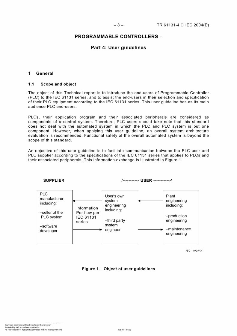
An objective of this user guideline is to facilitate communication between the PLC user and PLC supplier according to the specifications of the IEC 61131 series that applies to PLCs and their associated peripherals. This information exchange is illustrated in Figure 1.
Figure 1 – Object of user guidelines
SUPPLIER /----------- USER ------------\ Information Information flow per Per flow per IEC 61131 IEC 61131 series
User's own system engineering including:
–third party system engineer
PLC manufacturer including: –seller of the PLC system –software developer
Plant engineering including:
–production engineering
–maintenance engineering
IEC 1025/04
Copyright International Electrotechnical Commission Provided by IHS under license with IEC
Not for ResaleNo reproduction or networking permitted without license from IHS
--``````-`-`,,`,,`,`,,`---

TR 61131-4 IEC:2004(E) – 9 –
As depicted in Figure 1, the users consist of system integrators and end-users. The manufacturer of PLC is required by the IEC 61131 series to furnish appropriate product information to the user. Optionally, the user supplies operational requirements and specifications to the manufacturer in order to receive suitable products and services from the manufacturer. One objective of this Technical Report is therefore to assist in this communication, especially from the end-user's perspective. Accordingly, this Technical Report does not detail all the requirements of each and every part of the IEC 61131 series, such as conformance tests. The user should refer to the individual parts of the standard when needed.
1.2 Normative references
The following referenced documents are indispensable for the application of this document. For dated references, only the edition cited applies. For undated references, the latest edition of the referenced document (including any amendments) applies.
IEC 61131-1: Programmable controllers – Part 1: General information IEC 61131-2: Programmable controllers – Part 2: Equipment requirements and tests IEC 61131-3: Programmable controllers – Part 3: Programming languages IEC 61131-5: Programmable controllers – Part 5: Communications IEC 61131-7: Programmable controllers – Part 7: Fuzzy control programming IEC 61131-8: Programmable controllers – Part 8: Guidelines for the application and implementation of programming languages
1.3 Use of this report
A PLC application starts with the user's system analysis and specification. Inquiries and discussions (and suggestions/recommendations) with the manufacturer necessitate the use of a mutually agreed language for interactive information exchange as in Figure 1. The user can use this report as a basis and/or to supplement any in-house system design rules. The user can then specify the equipment and software requirements according to the relevant parts in the IEC 61131 series. In this user guideline, introductions and briefings of various parts of the IEC 61131 series are presented in Annex A according to the divisions in the IEC 61131 series. For example, Clause A.1 covers IEC 61131-1, Clause A.2 covers IEC 61131-2, etc.
This Technical Report presents only those specifications for which the user may have an immediate need for reference. It is not a complete summary of the whole IEC 61131 series.
Copyright International Electrotechnical Commission Provided by IHS under license with IEC
Not for ResaleNo reproduction or networking permitted without license from IHS
--``````-`-`,,`,,`,`,,`---

– 10 – TR 61131-4 IEC:2004(E)
2 Terms and definitions
For the purposes of this part of IEC 61131, the following terms and definitions, as well as those given in IEC 61131-1, apply.
2.1 application program (user program) logical assembly of all the programming language elements and constructs necessary for the intended signal processing required for the control of a machine or process by a PLC system
2.2 automated system control system beyond the scope of IEC 61131 in which PLC systems are incorporated by or for the user, but which also contains other components including their application programs
2.3 operator (human) person commanding and monitoring a machine or process through an HMI connected to the PLC. The operator does not change the PLC hardware configuration, software or the application program. A PLC is not intended for use by untrained personnel. The operator is assumed to be aware of the general hazards in an industrial environment.
2.4 programmable controller digitally operating electronic system, designed for use in an industrial environment, which uses a programmable memory for the internal storage of user-oriented instructions to implement specific functions (such as logic, sequencing, timing, counting and arithmetic) to control, through digital or analogue inputs and outputs, various types of machines or processes.
NOTE In the first edition of the IEC 61131 series, the acronym “PC” was used for Programmable Controller. However, usage of the earlier acronym PLC has been persisted with the majority of industries. After consultation, IEC Subcommittee 65B WG7 recommended that the more widely accepted acronym PLC be used, starting with all new editions of the IEC 61131 standard.
2.5 programmable controller system user-assembled configuration, consisting of a programmable controller and associated peripherals that is necessary for the intended automated system. It consists of units interconnected by cables or plug-in connections for permanent installation and by cables or other means for portable and transportable peripherals.
2.6 service personnel person changing or repairing the PLC hardware configuration or the application programme.
The service person may also install software updates provided by the manufacturer. They are assumed to be trained in the programming and operation of the PLC equipment and its use.
They are persons having the appropriate technical training and experience necessary to be aware of hazards – in particular, electrical hazards – to which they are exposed in performing a task and of measures to minimize danger to themselves or to other persons or to the equipment.
Copyright International Electrotechnical Commission Provided by IHS under license with IEC
Not for ResaleNo reproduction or networking permitted without license from IHS
--``````-`-`,,`,,`,`,,`---

TR 61131-4 IEC:2004(E) – 11 –
3 General recommendations for installation
The installation procedure should fulfil the requirements given by documents, which are prepared during the system selection/engineering/application phase. Not all site conditions can be recognized at the PLC selection phase. During installation, it is important to update all engineering and application documents according to how the PLC equipment is assembled or modified on site.
3.1 Environmental conditions
The user should ensure that care is taken concerning temperature, contaminants, shock, vibration and electromagnetic influence. Refer to IEC 61131-2 for specific environmental requirements. Table 1 describes environmental conditions to be evaluated during installation.
Table 1 – Environmental conditions
Criteria Comments and considerations
Temperature Check for possible influence of steady or temporary heat sources: - space heater - solar heat - hot goods passing by
Contaminants Moisture, corrosive gases, liquids and conductive dust can affect the function of a PLC system. Therefore, check: - use of adequate enclosures in compliance with international/national codes - compliance with manufacturer's installation instructions - degradation of thermal efficiency caused by dust
Shock and vibration Check for possible effects on site: - engines - compressors - transfer lines - presses, hammers - vehicles
Electromagnetic interference Check electromagnetic interference from various sources on site: - motors - switch gears, thyristors - radio-controlled equipment - welding equipment - electrical arcs - switched power supplies - power converters/inverters
3.2 Field wiring
Proper field wiring practices are of prime importance to the application of PLCs. The installer needs to follow the manufacturer's wiring instructions and applicable local regulations.
Two earthing/grounding requirements need to be fulfilled during installation: protective earth (safety grounding) and functional earth (signal ground reference).
Protective earthing requires the solid connection (e.g., low impedance connection, including star washers, welding, soldering, etc.) of inactive metal parts to an equipotential metallic grid (frames, chassis, cabinets). The grid needs to be connected to protective earth in accordance with local and national codes.
Functional earthing needs to be installed as the low impedance network of signal ground reference lines. It should be a network separate from protective earthing.
Protective and functional earth networks may be interconnected via wires or other low impedance paths. Such interconnections or lack thereof may be required by applicable local/national codes, or due to noise reduction requirements, depending on the type of controlled process/equipment. Table 2 describes installation rules of earthing measures.
Copyright International Electrotechnical Commission Provided by IHS under license with IEC
Not for ResaleNo reproduction or networking permitted without license from IHS
--``````-`-`,,`,,`,`,,`---
– 12 – TR 61131-4 IEC:2004(E)
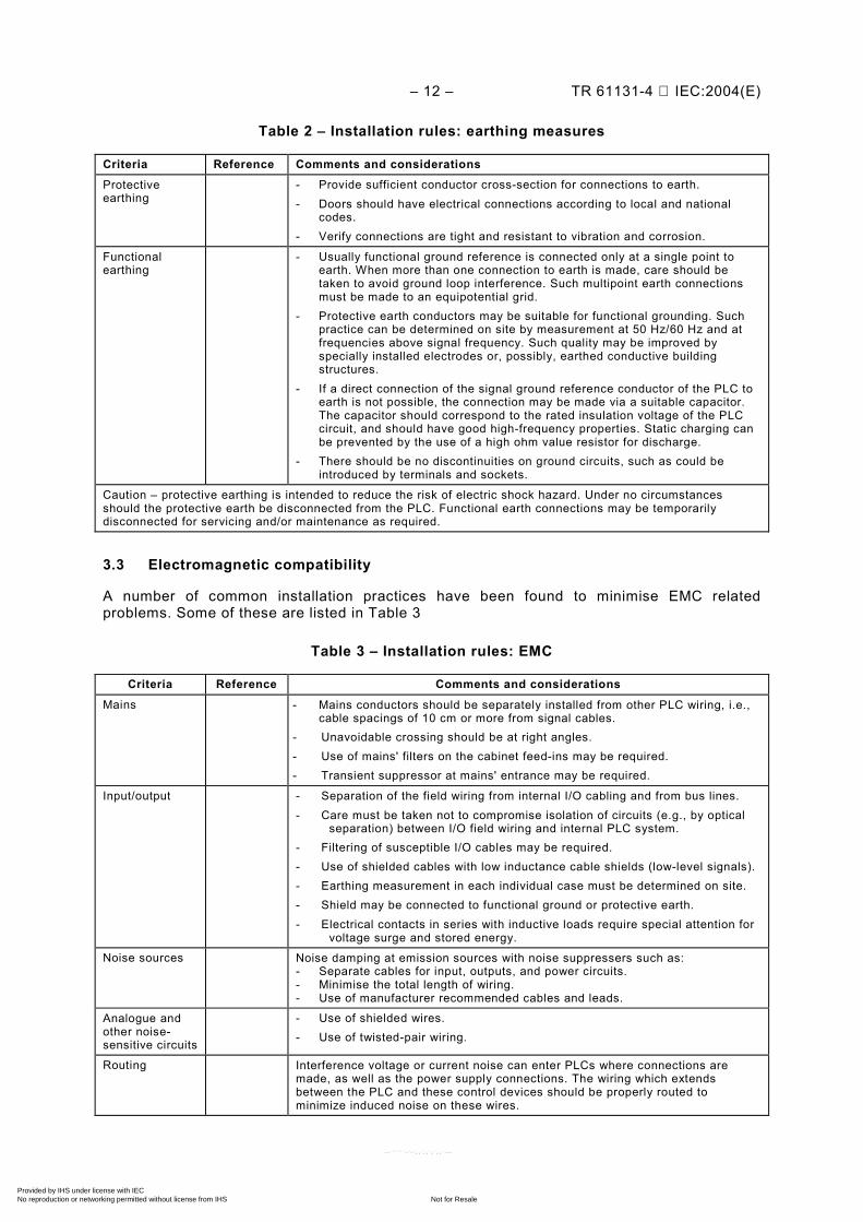
Table 2 – Installation rules: earthing measures
Criteria Reference Comments and considerations
Protective earthing
- Provide sufficient conductor cross-section for connections to earth. - Doors should have electrical connections according to local and national
codes. - Verify connections are tight and resistant to vibration and corrosion.
Functional earthing
- Usually functional ground reference is connected only at a single point to earth. When more than one connection to earth is made, care should be taken to avoid ground loop interference. Such multipoint earth connections must be made to an equipotential grid.
- Protective earth conductors may be suitable for functional grounding. Such practice can be determined on site by measurement at 50 Hz/60 Hz and at frequencies above signal frequency. Such quality may be improved by specially installed electrodes or, possibly, earthed conductive building structures.
- If a direct connection of the signal ground reference conductor of the PLC to earth is not possible, the connection may be made via a suitable capacitor. The capacitor should correspond to the rated insulation voltage of the PLC circuit, and should have good high-frequency properties. Static charging can be prevented by the use of a high ohm value resistor for discharge.
- There should be no discontinuities on ground circuits, such as could be introduced by terminals and sockets.
Caution – protective earthing is intended to reduce the risk of electric shock hazard. Under no circumstances should the protective earth be disconnected from the PLC. Functional earth connections may be temporarily disconnected for servicing and/or maintenance as required.
3.3 Electromagnetic compatibility
A number of common installation practices have been found to minimise EMC related problems. Some of these are listed in Table 3
Table 3 – Installation rules: EMC
Criteria Reference Comments and considerations
Mains - Mains conductors should be separately installed from other PLC wiring, i.e., cable spacings of 10 cm or more from signal cables.
- Unavoidable crossing should be at right angles. - Use of mains' filters on the cabinet feed-ins may be required. - Transient suppressor at mains' entrance may be required.
Input/output - Separation of the field wiring from internal I/O cabling and from bus lines. - Care must be taken not to compromise isolation of circuits (e.g., by optical
separation) between I/O field wiring and internal PLC system. - Filtering of susceptible I/O cables may be required. - Use of shielded cables with low inductance cable shields (low-level signals). - Earthing measurement in each individual case must be determined on site. - Shield may be connected to functional ground or protective earth. - Electrical contacts in series with inductive loads require special attention for
voltage surge and stored energy.
Noise sources Noise damping at emission sources with noise suppressers such as: - Separate cables for input, outputs, and power circuits. - Minimise the total length of wiring. - Use of manufacturer recommended cables and leads.
Analogue and other noise-sensitive circuits
- Use of shielded wires. - Use of twisted-pair wiring.
Routing Interference voltage or current noise can enter PLCs where connections are made, as well as the power supply connections. The wiring which extends between the PLC and these control devices should be properly routed to minimize induced noise on these wires.
Copyright International Electrotechnical Commission Provided by IHS under license with IEC
Not for ResaleNo reproduction or networking permitted without license from IHS
--``````-`-`,,`,,`,`,,`---
TR 61131-4 IEC:2004(E) – 13 –
3.4 User system markings
User system markings of components (sensors, actuators, cables, distribution-boards, enclosures, modules, etc.) should be done in accordance with the installation drawings and applicable codes.
Special care needs to be taken on markings of wiring. Each and every field wire should be identified with a marking corresponding to drawing. Alteration from the drawing should be noted on the same drawing immediately.
Care needs to be taken to ensure the following:
– markings need to be indelible; – adequate sizes of letters and signs; – fuse location, type, rating need to be clearly marked; – visibility of markings; and – conformity with installation drawings according to revision of final documents.
4 PLC in functional safety applications
When PLCs are required to perform safety functions, it is necessary that special measures be taken to avoid and limit dangerous failures of the functional-safety-related system. Detailed requirements for Safety-Related System (SRS) are contained in IEC 61508 and in emerging sector implementation standards such as the IEC 61511 series. The purpose of this Clause is to provide an overview of some of the functional safety issues that will need to be addressed. It is not intended to provide definitive or detailed guidance for implementation.
4.1 Functional safety and safety-related-system concept
Functional safety, as defined in IEC 61508, refers to the ability of a SRS to carry out the functions necessary to achieve a safe state for the Equipment Under Control (EUC) or to maintain a safe state for the EUC. In this definition, the main subject is focused on the ability of a safety-related system to do what it is required to do.
“Safety” refers to freedom from unacceptable risk. It follows that there are acceptable risks. The level of risks may be categorized as “broadly acceptable”, “tolerable” where further risk reduction is impracticable (the As Low As Reasonably Practical, ALARP, principle) and, the “intolerable” where risks cannot be justified, except in extraordinary circumstances. Risk level is assessed as a combination of “Consequence of hazardous event” and “Frequency of hazardous event”.
The task of a SRS is to reduce the risk to a tolerable level or lower as prescribed by the control system designer. This risk-reduction model is depicted in Figure 2.
NOTE 1 The IEC 61131 series does not deal with the functional safety or other safety aspects of the overall automated system. Safety considerations for the overall automated system are beyond the scope of this standard.
NOTE 2 The IEC 61131 series does not contain a part on functional safety. At the preparation of this part of IEC 61131, a sector standard for PLC and similar equipment is under consideration.
NOTE 3 Safety, as covered in IEC 61131-2, refers to prevention of electric shock and fire hazards.
Copyright International Electrotechnical Commission Provided by IHS under license with IEC
Not for ResaleNo reproduction or networking permitted without license from IHS
--``````-`-`,,`,,`,`,,`---

– 14 – TR 61131-4 IEC:2004(E)
Figure 2 – SRS in risk reduction concept
Each SRS is assigned Safety Functions and is to fulfil the safety functions with a prescribed Safety Integrity Level (SIL) requirement. IEC 61508 categorises SIL in four levels as listed in Table 4 for Demand Mode and in Table 5 for Continuous Mode.
Table 4 – SIL of demand mode safety functions
SIL Average probability of failure to perform the safety function on demand (PFD)
4 ≥ 10–5 to < 10–4
3 ≥ 10–4 to < 10–3
2 ≥ 10–3 to < 10–2
1 ≥ 10–2 to < 10–1
Table 5 – SIL of continuous mode safety functions
SIL Probability of a dangerous failure of the safety function (per hour)
4 ≥ 10–9 to < 10–8
3 ≥ 10–8 to < 10–7
2 ≥ 10–7 to < 10–6
1 ≥ 10–6 to < 10–5
Note that Table 5 can also be used for Demand Mode safety functions when the demand rate is high compared with the proof test frequency of the safety function. Typically, when the demand rate is higher than twice the proof test frequency, then it is reasonable to specify the safety function in terms of probability of failure per hour using Table 5.
The international standard for safety instrumented system for the process industry is the IEC 61511 series. In the IEC 61511 series, the safety instrumented system (SIS) includes all components and subsystems necessary to carry out the safety instrumented function, from sensor(s) to actuator(s).
Low EUC RISK LEVEL High
Actual remaining risk
Tolerable risk level
Inherit risk of EUC (including the addition of protective features)
Risk reduction achieved by SRS #2 (e.g. PLC used at SIL 4, 3, or 2 as specified)
Risk reduction achieved by SRS #1
IEC 1026/04
Copyright International Electrotechnical Commission Provided by IHS under license with IEC
Not for ResaleNo reproduction or networking permitted without license from IHS
--``````-`-`,,`,,`,`,,`---
TR 61131-4 IEC:2004(E) – 15 –
For the machine sector, IEC 62061 is in preparation. This standard is being harmonized with international standard ISO 13849-1 (EN 954-1). The Safety-Related Part (SRP) which carries out safety functions is viewed as a component of the total control system. The ability of SRP to fulfil a safety function is described as Performance Levels (PL). Performance Levels PL-a, PL-b, PL-c, PL-d, and PL-e correspond to the “average probability of a dangerous failure per hour” ranging from 10–4 to 10–8. The required PL (for a SRP) is determined on risk parameters of “Severity of injury”, “Frequency and/or exposure time to the hazard” and “Probability of avoiding the hazard”. Each of these parameters is categorized as high or low. PL-a describes risks lower than SIL1. PL-b and c approximately correspond to SIL1. PL-d corresponds to SIL2 and PL-e corresponds to SIL3. A SRP is then specified as one of five categories: Basic, 1, 2, 3, and 4.
4.2 Using a PLC in a safety-related application
When applying a PLC in a safety-related application (that is, an application where a failure of the SRS to carry out its intended safety function could lead to injury, loss of life or damage to health), then it will be necessary to take into account the likelihood of dangerous failure due to random hardware faults. It will also be necessary to address the possibility of systematic faults in hardware and software.
Notice that safety-related applications should not be confused with basic control applications where there are other measures, such as safety interlocks, which provide protection in the event of such failure.
In safety-related applications, a PLC will usually form only one part of a programmable electronic safety-related system. The other parts, or subsystems, of the SRS include switches and/or sensors as input devices and contactors and/or valves as output actuators.
4.2.1 Safety functions
In order to determine the particular requirements for a PLC used in a safety-related application, it is first necessary to specify the entire safety requirements of the safety-related system.
The safety requirements of a programmable electronic SRS are assigned safety functions. Each safety function required to be carried out by the SRS is specified in terms of Safety Function and Safety Integrity Level (SIL). The safety functional specification is a description of the required function in terms of the action of the safety-related system under a specific set of circumstances.
It is very important that the safety functional specification also needs to include a description of any states of the system which should be avoided in order to prevent hazardous situations. For example, in the case of a system used for an emergency stop safety function on a machine tool, it is necessary to ensure that the machine does not restart when the emergency stop actuator is reset. The machine restarts only when all faults are cleared and a start command is given.
4.2.2 Safety Integrity Level (SIL)
The Safety Integrity Level (SIL) part of the safety functions specification is a measure of the target acceptable probability of failure of the safety function. To determine the SIL level for a safety function, it is necessary to take into account the hazards and risks associated with the application together with the tolerable risk target, and any contribution to risk reduction provided by other safety measures. Generic methods for SIL determination are given in IEC 61508-5. Sector functional safety standards provide guidance relevant to particular applications (see, for example, IEC 61511-3 for the process sector or IEC 62061 for the machinery sector).
Copyright International Electrotechnical Commission Provided by IHS under license with IEC
Not for ResaleNo reproduction or networking permitted without license from IHS
--``````-`-`,,`,,`,`,,`---
– 16 – TR 61131-4 IEC:2004(E)
Experts in the industry have found that in order to achieve the required reduction of dangerous failure rates required for higher levels of safety integrity (e.g. SIL3 and above), it may be necessary to employ redundant architectures (e.g. 2 out of 3 voting), even taking into account the high levels of diagnostic coverage (e.g. >99 %) typically seen in such PLCs.
4.3 Requirements on PLCs in a safety-related system
In order for a safety-related system to meet the requirements of IEC 61508 or associated sector standards, it is necessary that the following characteristics of a PLC used in the safety-related system be taken account of when designing a safety-related system to carry out a safety function with a specified SIL:
– hardware reliability; – diagnostic test coverage and test interval; – periodic testing/maintenance requirements; – hardware fault tolerance; and – SIL capability.
This information should be obtained from the PLC manufacturer.
Notice that the ‘SIL capability’ is the highest SIL which can be claimed for a safety function which uses the PLC, taking into account the measures and techniques used for the avoidance and control of systematic faults in the PLC hardware and software (including system software and firmware) according to IEC 61508. Note also that in order to determine the actual SIL that can be claimed for a safety function in a particular application, it is necessary to consider all of the above characteristics for all of the subsystems which contribute to the safety function.
4.4 Integration of PLC into a safety-related system
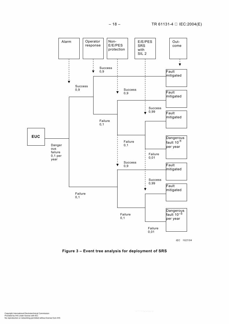
The process for deployment of protective features may be illustrated in the event analysis diagram in Figure 3.
The activities undertaken to integrate a PLC into a safety-related system include the development of application software safety requirements. Application programming or configuration and testing should be carried out and verified according to the requirements of IEC 61508 or associated sector standards. It will be necessary to determine how frequently it is required to undertake proof tests in order to detect any dangerous faults which are not revealed by the automatic diagnostic tests. Proof tests are particularly important when PLCs are applied in redundant configurations, or when there are components (such as batteries) whose failure may not be apparent during normal operation.
If previously developed application software library functions are to be used, their suitability in satisfying the software safety requirements specifications need to be verified. Suitability may be based on evidence of satisfactory operation in a similar application which has been demonstrated to have similar functionality or having been subject to the same verification and validation procedures as would be expected for newly developed software. Any constraints from the previous software environment (for example operating system and compiler dependencies, order of execution of library functions, etc.) need to be evaluated.
Application programs should be well documented, including at the least the following information:
– legal entity (e.g.: company, author(s), etc.); – description; – tractability to application functional requirements; – logic conventions used; – standard library functions used (and associated justifications, see above);
Copyright International Electrotechnical Commission Provided by IHS under license with IEC
Not for ResaleNo reproduction or networking permitted without license from IHS
--``````-`-`,,`,,`,`,,`---

TR 61131-4 IEC:2004(E) – 17 –
– inputs and outputs; and – configuration management including a history of changes.
All integration (including hardware, software, mechanical assembly and wiring, use of tools and programming languages, interfacing of inputs and outputs) need to be in accordance with instructions of the PLC manufacturer.
Note that extreme caution should be exercised when combining PLCs in redundant architectures in order to meet hardware reliability requirements. Such architectures could introduce the possibility of systematic failure modes associated with timing synchronization and voting which may outweigh the benefits to be gained from redundancy.
Integration should take into account the possibility of reasonably foreseeable fault conditions, such as open circuits on inputs or power supply failure, so as to ensure that such fault conditions do not lead to hazardous situations.
Care should be taken to ensure that it is not possible, during use of the PLC, for a previous version of an application program (e.g. stored in NVRAM) to over-write an application program which may have been changed to remove faults. Such over-writing could lead to software faults being re-introduced.
Copyright International Electrotechnical Commission Provided by IHS under license with IEC
Not for ResaleNo reproduction or networking permitted without license from IHS
--``````-`-`,,`,,`,`,,`---
– 18 – TR 61131-4 IEC:2004(E)
Figure 3 – Event tree analysis for deployment of SRS
Out- come
E/E/PES SRS with SIL 2
Non-E/E/PES protection
Operator response
Alarm
Fault mitigated
Fault mitigated
Fault mitigated
Dangerous fault 10-6
per year
Fault mitigated
Fault mitigated
Dangerous fault 10–5 per year
EUC
Danger ous failure 0,1 per year
Success 0,9
Success 0,9
Failure 0,1
Success 0,9
Failure 0,1
Success 0,9
Failure 0,1
Failure 0,1
Success 0,99
Failure 0,01
Failure 0,01
Success 0,99
IEC 1027/04
Copyright International Electrotechnical Commission Provided by IHS under license with IEC
Not for ResaleNo reproduction or networking permitted without license from IHS
--``````-`-`,,`,,`,`,,`---
TR 61131-4 IEC:2004(E) – 19 –
Annex A (informative)
Overview of normative parts of IEC 61131
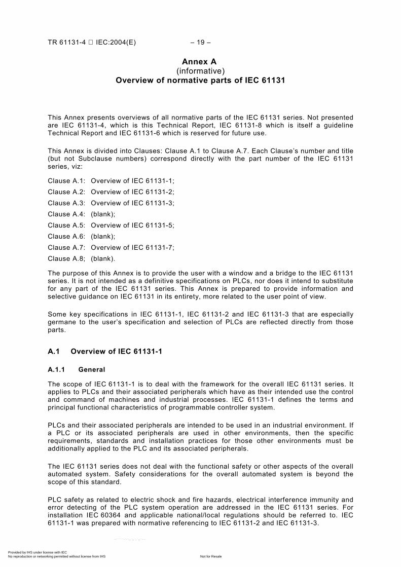
This Annex presents overviews of all normative parts of the IEC 61131 series. Not presented are IEC 61131-4, which is this Technical Report, IEC 61131-8 which is itself a guideline Technical Report and IEC 61131-6 which is reserved for future use.
This Annex is divided into Clauses: Clause A.1 to Clause A.7. Each Clause’s number and title (but not Subclause numbers) correspond directly with the part number of the IEC 61131 series, viz:
Clause A.1: Overview of IEC 61131-1; Clause A.2: Overview of IEC 61131-2; Clause A.3: Overview of IEC 61131-3; Clause A.4: (blank); Clause A.5: Overview of IEC 61131-5; Clause A.6: (blank); Clause A.7: Overview of IEC 61131-7; Clause A.8; (blank).
The purpose of this Annex is to provide the user with a window and a bridge to the IEC 61131 series. It is not intended as a definitive specifications on PLCs, nor does it intend to substitute for any part of the IEC 61131 series. This Annex is prepared to provide information and selective guidance on IEC 61131 in its entirety, more related to the user point of view.
Some key specifications in IEC 61131-1, IEC 61131-2 and IEC 61131-3 that are especially germane to the user’s specification and selection of PLCs are reflected directly from those parts.
A.1 Overview of IEC 61131-1
A.1.1 General
The scope of IEC 61131-1 is to deal with the framework for the overall IEC 61131 series. It applies to PLCs and their associated peripherals which have as their intended use the control and command of machines and industrial processes. IEC 61131-1 defines the terms and principal functional characteristics of programmable controller system.
PLCs and their associated peripherals are intended to be used in an industrial environment. If a PLC or its associated peripherals are used in other environments, then the specific requirements, standards and installation practices for those other environments must be additionally applied to the PLC and its associated peripherals.
The IEC 61131 series does not deal with the functional safety or other aspects of the overall automated system. Safety considerations for the overall automated system is beyond the scope of this standard.
PLC safety as related to electric shock and fire hazards, electrical interference immunity and error detecting of the PLC system operation are addressed in the IEC 61131 series. For installation IEC 60364 and applicable national/local regulations should be referred to. IEC 61131-1 was prepared with normative referencing to IEC 61131-2 and IEC 61131-3.
Copyright International Electrotechnical Commission Provided by IHS under license with IEC
Not for ResaleNo reproduction or networking permitted without license from IHS
--``````-`-`,,`,,`,`,,`---
– 20 – TR 61131-4 IEC:2004(E)
A.1.2 Terms and definitions
Some of the terms and definitions used in IEC 61131-1 are as follows:
a) Field devices catalogued part to provide input and/or output interface or to provide data pre-conditioning.
NOTE The abbreviation “PLC” is used in this standard to stand for “programmable controllers”, as is the common practice in the automation industry. The use of “PC” as abbreviation to “programmable controllers” leads to confusion with personal computers.
b) Programmable Controller system (PLC system) user-built configuration, consisting of a programmable controller and associated peri-
pherals, that is necessary for the intended automated system. It consists of units interconnected by cables or plug-in connections for permanent installation and by cables or other means for portable and transportable peripherals.
c) Programming And Debugging Tool (PADT) catalogued peripheral to assist in programming, testing, commissioning and trouble-
shooting the PLC system application, program storage and documentation. PADTs may be used as Human-Machine-Interface (HMI). PADTs are said to be pluggable when they may be plugged or unplugged into their associated interface at any time without any risk to the operator and the application. In all other cases, PADTs are said to be fixed.
d) Remote Input/Output Station (RIOS) manufacturer’s catalogued part of a PLC system, including input and/or output interfaces
allowed to operate only under the hierarchy of the main processing unit (CPU) for I/O multiplexing/de-multiplexing and dated pre-processing/post-processing. The RIOS is the only peripheral permitted to have limited autonomous operation, for example, under emergency conditions such as breakdown of the communication link to the CPU, or when maintenance and trouble-shooting operations are to be performed.
A.1.3 Functional characteristics
A.1.3.1 Basic functional structure of a PLC system
The structure of a PLC system and communication interfaces are illustrated in Figure A.1, Figure A.2 and Figure A.3. These models are the basis of IEC 61131-2 on hardware, IEC 61131-3 on programming, IEC 61131-5 on communication and IEC 61131-7 on fuzzy programming.
Copyright International Electrotechnical Commission Provided by IHS under license with IEC
Not for ResaleNo reproduction or networking permitted without license from IHS
--``````-`-`,,`,,`,`,,`---

TR 61131-4 IEC:2004(E) – 21 –
Figure A.1 – Basic functional structure of a PLC system
Power supply function
Mains supply
Other systems
INTERFACE functions tosensors and actuators
Machine/Process
Application programmer
Operator
Communicationfunctions
Programming debugging and testing functions
Man-machine interface functions
Data storage functions
Application program storage functions
Operating system functions
Application program Execution
Signal processing functions
IEC 1028/04
Copyright International Electrotechnical Commission Provided by IHS under license with IEC
Not for ResaleNo reproduction or networking permitted without license from IHS
--``````-`-`,,`,,`,`,,`---
– 22 – TR 61131-4 IEC:2004(E)
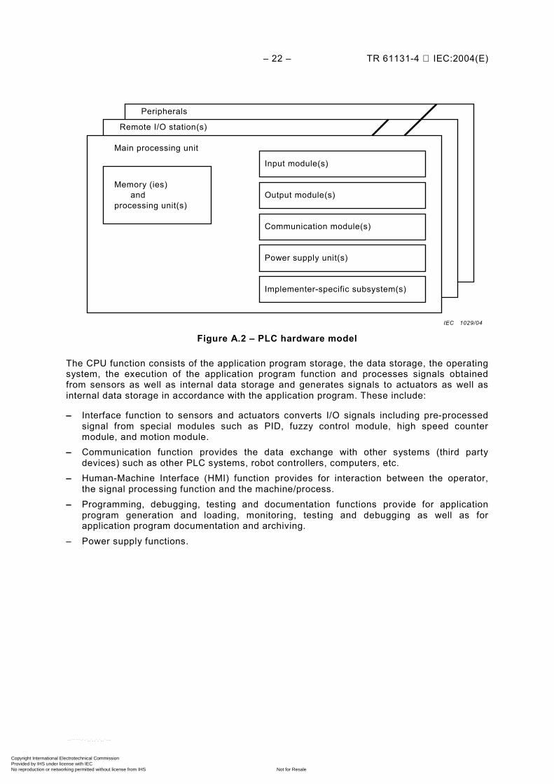
Figure A.2 – PLC hardware model
The CPU function consists of the application program storage, the data storage, the operating system, the execution of the application program function and processes signals obtained from sensors as well as internal data storage and generates signals to actuators as well as internal data storage in accordance with the application program. These include:
– Interface function to sensors and actuators converts I/O signals including pre-processed signal from special modules such as PID, fuzzy control module, high speed counter module, and motion module.
– Communication function provides the data exchange with other systems (third party devices) such as other PLC systems, robot controllers, computers, etc.
– Human-Machine Interface (HMI) function provides for interaction between the operator, the signal processing function and the machine/process.
– Programming, debugging, testing and documentation functions provide for application program generation and loading, monitoring, testing and debugging as well as for application program documentation and archiving.
– Power supply functions.
Memory (ies)and
processing unit(s)
Input module(s)
Output module(s)
Communication module(s)
Power supply unit(s)
Main processing unit
Remote I/O station(s)
Peripherals
Implementer-specific subsystem(s)
IEC 1029/04
Copyright International Electrotechnical Commission Provided by IHS under license with IEC
Not for ResaleNo reproduction or networking permitted without license from IHS
--``````-`-`,,`,,`,`,,`---
TR 61131-4 IEC:2004(E) – 23 –
Limit of the scope of this standard Interfaced devices and signals
Open communication signals interface/port(internal communications also open to third party devices
BeHK G
Bi
Be
Be
Be Bi
Bi
Bi
G H
H
Auxiliary Power Supply (optional)
Functional earthing port
Protective earthing port
Peripheral(permanently /non-permanently installed)
Mains power input interface/port
Digital and analoginput signal interface/port I/O power interface/port
I/O power interface/port Digital and analogoutput signal interface/port
Communication signals interface/port with third party devices (computers, printers, fieldbus , etc)
Auxiliary power output interface/port (to provide energy for sensors and actuators)
Input Module(s)
Commu - nication Modules (optional)
Memory ( ies ) and Processing Unit(s)
Power Supply
Local extension rack
Basic PLC
Remote IOs
Output Module(s)
Al
Ar
C
C
C
C
G
G H
F
F
F
F
E
E
E
E
D
D
D
D
K
K
K
J
J
J
J
J
J
J
J
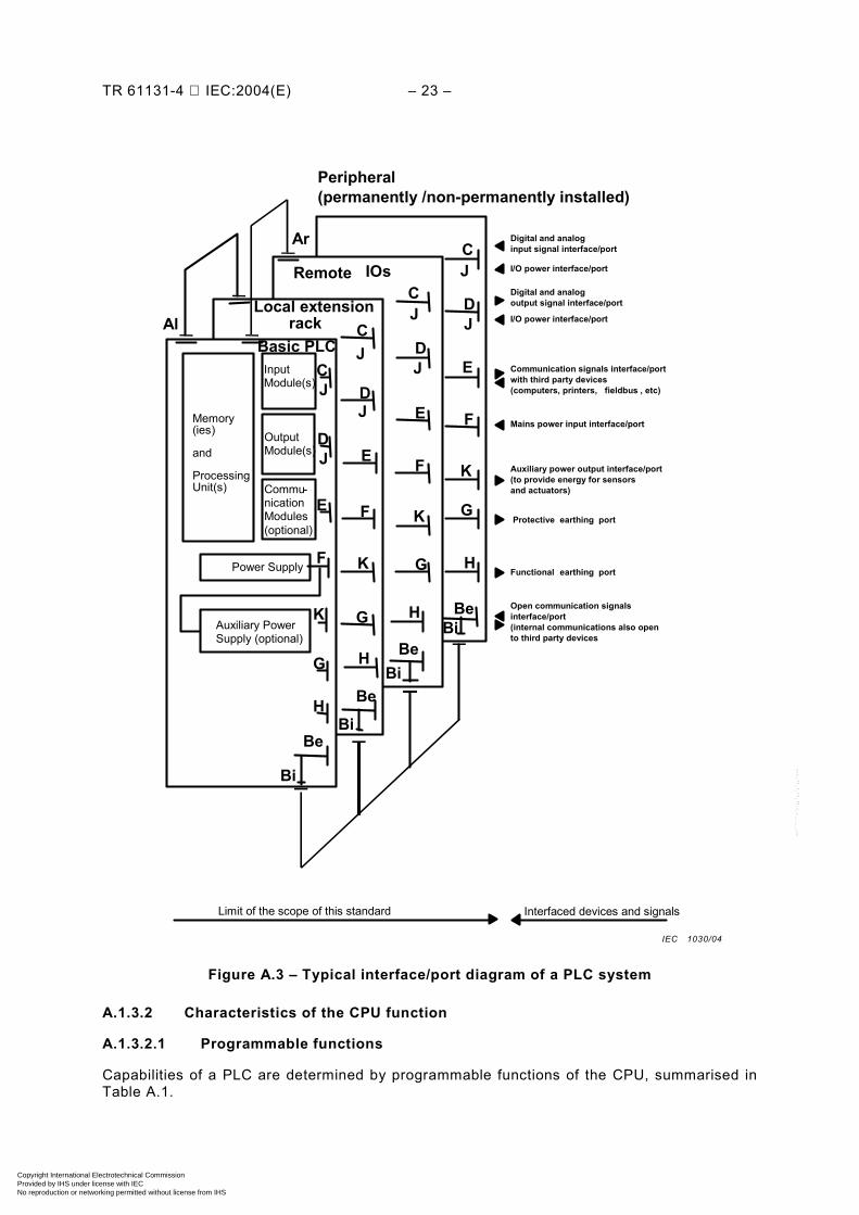
Figure A.3 – Typical interface/port diagram of a PLC system
A.1.3.2 Characteristics of the CPU function
A.1.3.2.1 Programmable functions
Capabilities of a PLC are determined by programmable functions of the CPU, summarised in Table A.1.
IEC 1030/04
Copyright International Electrotechnical Commission Provided by IHS under license with IEC
Not for ResaleNo reproduction or networking permitted without license from IHS
--``````-`-`,,`,,`,`,,`---
– 24 – TR 61131-4 IEC:2004(E)
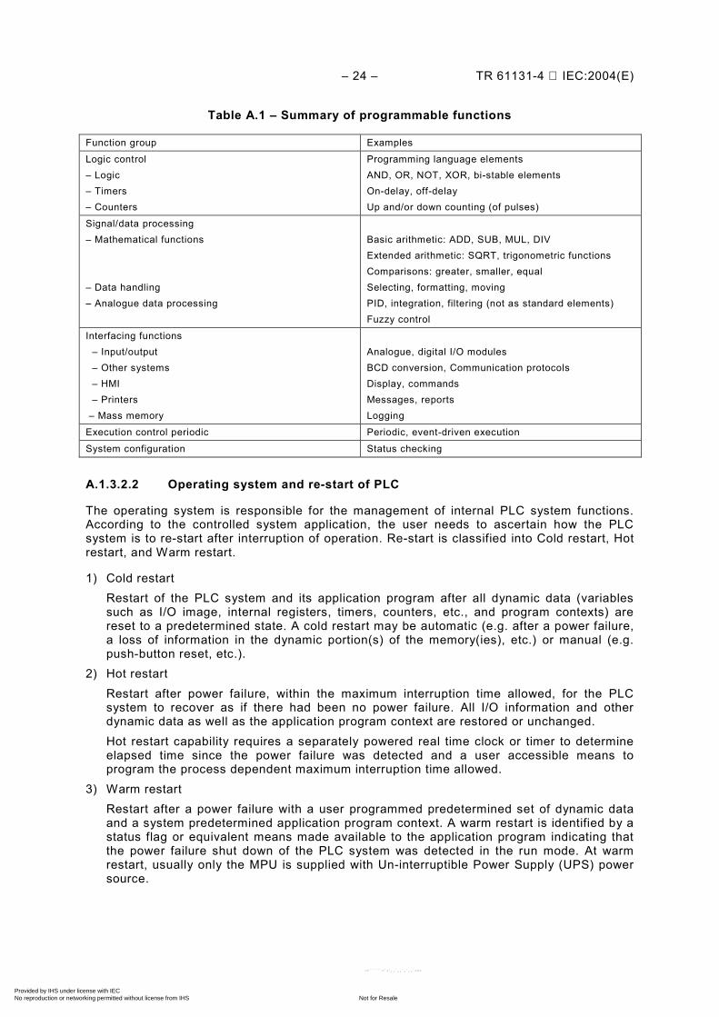
Table A.1 – Summary of programmable functions
Function group Examples
Logic control – Logic – Timers – Counters
Programming language elements AND, OR, NOT, XOR, bi-stable elements On-delay, off-delay Up and/or down counting (of pulses)
Signal/data processing – Mathematical functions – Data handling – Analogue data processing
Basic arithmetic: ADD, SUB, MUL, DIV Extended arithmetic: SQRT, trigonometric functions Comparisons: greater, smaller, equal Selecting, formatting, moving PID, integration, filtering (not as standard elements) Fuzzy control
Interfacing functions – Input/output – Other systems – HMI – Printers – Mass memory
Analogue, digital I/O modules BCD conversion, Communication protocols Display, commands Messages, reports Logging
Execution control periodic Periodic, event-driven execution
System configuration Status checking
A.1.3.2.2 Operating system and re-start of PLC
The operating system is responsible for the management of internal PLC system functions. According to the controlled system application, the user needs to ascertain how the PLC system is to re-start after interruption of operation. Re-start is classified into Cold restart, Hot restart, and Warm restart.
1) Cold restart Restart of the PLC system and its application program after all dynamic data (variables
such as I/O image, internal registers, timers, counters, etc., and program contexts) are reset to a predetermined state. A cold restart may be automatic (e.g. after a power failure, a loss of information in the dynamic portion(s) of the memory(ies), etc.) or manual (e.g. push-button reset, etc.).
2) Hot restart Restart after power failure, within the maximum interruption time allowed, for the PLC
system to recover as if there had been no power failure. All I/O information and other dynamic data as well as the application program context are restored or unchanged.
Hot restart capability requires a separately powered real time clock or timer to determine elapsed time since the power failure was detected and a user accessible means to program the process dependent maximum interruption time allowed.
3) Warm restart Restart after a power failure with a user programmed predetermined set of dynamic data
and a system predetermined application program context. A warm restart is identified by a status flag or equivalent means made available to the application program indicating that the power failure shut down of the PLC system was detected in the run mode. At warm restart, usually only the MPU is supplied with Un-interruptible Power Supply (UPS) power source.
Copyright International Electrotechnical Commission Provided by IHS under license with IEC
Not for ResaleNo reproduction or networking permitted without license from IHS
--``````-`-`,,`,,`,`,,`---
TR 61131-4 IEC:2004(E) – 25 –
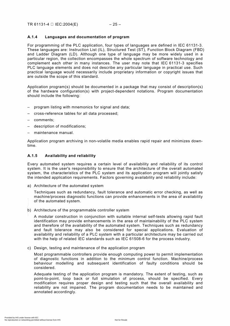
A.1.4 Languages and documentation of program
For programming of the PLC application, four types of languages are defined in IEC 61131-3. These languages are: Instruction List (IL), Structured Test (ST), Function Block Diagram (FBD) and Ladder Diagram (LD). Although one type of language may be more widely used in a particular region, the collection encompasses the whole spectrum of software technology and complement each other in many instances. The user may note that IEC 61131-3 specifies PLC language elements and does not describe any particular language in practical use. Such practical language would necessarily include proprietary information or copyright issues that are outside the scope of this standard.
Application program(s) should be documented in a package that may consist of description(s) of the hardware configuration(s) with project-dependent notations. Program documentation should include the following:
– program listing with mnemonics for signal and data; – cross-reference tables for all data processed; – comments; – description of modifications; – maintenance manual.
Application program archiving in non-volatile media enables rapid repair and minimizes down-time.
A.1.5 Availability and reliability
Every automated system requires a certain level of availability and reliability of its control system. It is the user's responsibility to ensure that the architecture of the overall automated system, the characteristics of the PLC system and its application program will jointly satisfy the intended application requirements. Factors governing availability and reliability include:
a) Architecture of the automated system Techniques such as redundancy, fault tolerance and automatic error checking, as well as
machine/process diagnostic functions can provide enhancements in the area of availability of the automated system.
b) Architecture of the programmable controller system A modular construction in conjunction with suitable internal self-tests allowing rapid fault
identification may provide enhancements in the area of maintainability of the PLC system and therefore of the availability of the automated system. Techniques such as redundancy and fault tolerance may also be considered for special applications. Evaluation of availability and reliability of a PLC system with a particular architecture may be carried out with the help of related IEC standards such as IEC 61508-6 for the process industry.
c) Design, testing and maintenance of the application program Most programmable controllers provide enough computing power to permit implementation
of diagnostic functions in addition to the minimum control function. Machine/process behaviour modelling and subsequent identification of faulty conditions should be considered.
Adequate testing of the application program is mandatory. The extent of testing, such as point-to-point, loop back or full simulation of process, should be specified. Every modification requires proper design and testing such that the overall availability and reliability are not impaired. The program documentation needs to be maintained and annotated accordingly.
Copyright International Electrotechnical Commission Provided by IHS under license with IEC
Not for ResaleNo reproduction or networking permitted without license from IHS
--``````-`-`,,`,,`,`,,`---
– 26 – TR 61131-4 IEC:2004(E)
d) Installation and service conditions PLC systems are typically of rugged design and construction intended for general purpose
service. The more stressful the service conditions are, the more degradation is possible for availability and reliability. Conversely, improvements in availability and reliability may be expected when actual service conditions are less stressful than the normal service conditions specified in IEC 61131-2.
Some applications may require consideration of special enclosure, cooling, electrical noise protection, etc., for reliable operation.
A.2 Overview of IEC 61131-2
A.2.1 General
A.2.1.1 Scope and objectives
IEC 61131-2 establishes the functional, electrical safety, electromagnetic compatibility (EMC) and electrical, mechanical, environmental and construction requirements for the PLC and specifies testing methods accordingly. This standard covers PLCs and any products performing the function of PLCs and their associated peripherals. Only equipment intended for use in an industrial environment for control and command of machines and industrial processes are covered.
This standard also applies to any products performing the function of PLCs and/or their peripherals.
Equipment covered in IEC 61131-2 are intended for use in Overvoltage Category II as per IEC 60664-1 in low-voltage installations where the rated mains supply does not exceed 1 000 V r.m.s. or 1 500 V DC.
The object of IEC 61131-2 is to establish the definitions and identify the principle characteristics relevant to the selection and application of PLCs and their associated peripherals. It specifies the minimum requirements for functional, electrical, mechanical, environmental and construction characteristics, service conditions, safety, EMC, user programming and tests applicable to PLCs and the associated peripherals.
A.2.1.2 Compliance with this standard
When compliance with IEC 61131-2 is indicated without qualification, compliance with all clauses, including all tests and verifications required in IEC 61131-2, must be verified. Moreover, the manufacturer’s obligations expressed in IEC 61131-2 are not waived if no type test is required, or if the test conditions are restricted for practical reasons.
When compliance with some portion of IEC 61131-2 is indicated, it is only necessary to verify compliance with those clauses against which the compliance claim is made. The manufacturer’s obligations as indicated above are still applicable. The smallest unit of IEC 61131-2 for compliance purposes is a Clause, such as Functional Requirements, Immunity Requirements, Safety Requirements, etc.
All requirements not tested according to Tests and Verifications Clauses need to be verifiable under a procedure to be agreed upon by the manufacturer and the user. The manufacturer needs to provide, on request, compliance verification information for all requirements referenced in the claims of compliance with all or a portion of this standard.
Copyright International Electrotechnical Commission Provided by IHS under license with IEC
Not for ResaleNo reproduction or networking permitted without license from IHS
--``````-`-`,,`,,`,`,,`---
TR 61131-4 IEC:2004(E) – 27 –
A.2.1.3 Normative references
IEC 61131-2 lists some 28 normative references, including:
IEC 60068-2-1, Environmental testing - Part 2: Tests. Tests A: Cold
IEC 60364-4-443, Electrical installations of buildings – Part 4: Protection for safety – Chapter 44: Protection against overvoltages – Section 443: Protection against overvoltages of atmospheric origin or due to switching
IEC 60417-DB:20021, Graphical symbols for use on equipment
IEC 60529, Degrees of protection provided by enclosures (IP Code)
IEC 60664-1:1992, Insulation coordination for equipment within low-voltage systems – Part 1: Principles, requirements and tests
IEC 60664-3:1992, Insulation coordination for equipment within low-voltage systems – Part 3: Use of coatings to achieve insulation coordination of printed board assemblies
IEC 60695-2-1, Fire hazard testing – Part 2: Test methods – Section 1: Glow-wire test and methods
IEC 60707, Flammability of solid non-metallic materials when exposed to flame sources – List of test methods
IEC 60947, Low-voltage switchgear and controlgear
IEC 60950, Safety of information technology equipment, including electrical business equipment
IEC 60947-5-1:1997, Low-voltage switchgear and controlgear – Part 5-1: Control circuit devices and switching elements – Electromechanical control circuit devices
IEC 60947-7-1:2002, Low-voltage switchgear and controlgear – Part 7-1: Ancillary equipment – Terminal blocks for copper conductors IEC 60950-1:2001, Information technology equipment–Safety – Part 1: General requirements
IEC 61000-4-2:1995, Electromagnetic compatibility (EMC) – Part 4-2: Testing and measure-ment techniques – Electrostatic discharge immunity test
IEC 61000-4-3:2002, Electromagnetic compatibility (EMC) – Part 4-3: Testing and measure-ment techniques – Radiated radio-frequency electromagnetic field immunity test
IEC 61000-4-4:1995, Electromagnetic compatibility (EMC) – Part 4: Testing and measurement techniques – Section 4: Electrical fast transient/burst immunity test
IEC 61000-4-5:1995, Electromagnetic compatibility (EMC) – Part 4-5: Testing and measure-ment techniques – Surge immunity test
IEC 61000-4-6:1996, Electromagnetic compatibility (EMC) – Part 4-6: Testing and measure-ment techniques – Immunity to conducted disturbances induced by radio-frequency fields
——————— 1 "DB" refers to the IEC on-line database.
Copyright International Electrotechnical Commission Provided by IHS under license with IEC
Not for ResaleNo reproduction or networking permitted without license from IHS
--``````-`-`,,`,,`,`,,`---
– 28 – TR 61131-4 IEC:2004(E)
IEC 61000-4-8:1993, Electromagnetic compatibility (EMC) – Part 4-8: Testing and measure-ment techniques – Power frequency magnetic field immunity test
IEC 61000-4-12:1995, Electromagnetic compatibility (EMC) – Part 4-12: Testing and measure-ment techniques – Oscillatory waves immunity test
IEC 61010-1:2001, Safety requirements for electrical equipment for measurement, control, and laboratory use – Part 1: General requirements
CISPR 11:1999, Industrial, scientific and medical (ISM) radio-frequency equipment – electromagnetic disturbance characteristics – limits and methods of measurement
CISPR 16-1:1999, Specification for radio disturbance and immunity measuring apparatus and methods. – Part 1: Radio disturbance and immunity measuring apparatus
CISPR 16-2:1999, Specification for radio disturbance and immunity measuring apparatus and methods. – Part 2: Methods of measurement of disturbances and immunity
A.2.2 Terms and definitions
Some basic PLC equipment related definitions are listed in this Clause.
a) clearance Shortest distance in air between two conductive parts. b) creepage distance shortest distance along the surface of the insulating material between two conductive
parts. c) digital input types
Type1 Digital Input senses signal from mechanical contacts such as pushbuttons.
Type 2 Digital Input senses signals from solid state switching devices such as 2-wire proximity switches. This class could also be used for type 1 or type 3 applications.
Type 3 Digital Input senses signals from solid state switching devices only.
d) earth, functional earth, protective earth
Earth refers to part of the earth globe considered as conductive, the electrical potential of which is conventionally taken as zero.
Functional Earth is a conductor that is in electrical contact with earth for purposes of interference immunity improvement.
Protective Earth is a conductor in electrical contact with earth for purposes of safety. e) Electro-Magnetic Compatibility (EMC) The ability of an equipment or system to function satisfactorily in its electromagnetic
environment without introducing intolerable electromagnetic disturbances to anything in that environment.
NOTE 1 According to IEV 161-01-07.
f) equipment class Equipment classes, or Protection classes, designate the means by which electric shock
protection is maintained in normal use and single fault conditions:
Copyright International Electrotechnical Commission Provided by IHS under license with IEC
Not for ResaleNo reproduction or networking permitted without license from IHS
--``````-`-`,,`,,`,`,,`---
TR 61131-4 IEC:2004(E) – 29 –
Class I Equipment are those with protection against electric shock which does not only rely on basic insulation, but also include means by which accessible conductive parts cannot become live in the event of a failure of the basic insulation.
Class II Equipment are those with protection against electric shock which does not rely on basic insulation only but also include additional safety precautions such as double insulation or reinforced insulation.
Class III Equipment are which protection against electric shock is provided by circuits supplied by Safety Extra-Low Voltage (SELV, 30 V r.m.s., 42,4 V peak or 60 V DC) and where voltages generated do not exceed the limits for SELV.
g) functional earthing conductor A conductor that is in electrical contact with earth or earth equal-potential, for example
those used for purposes of interference immunity improvement. h) hazardous live Capable of rendering an electric shock or electric burn in normal conditions or single fault
conditions. i) hazardous voltage Hazardous voltage is which under normal conditions exceeds either 30 V r.m.s., or 42,4 V
peak. j) immunity (to a disturbance) The ability of a device, equipment or system to perform without degradation in the
presence of an electromagnetic disturbance. NOTE 2 Definition according to IEV 161-01-20.
NOTE 3 Immunity may also refer to no degradation of performance in the presence of vibration, humidity, etc.
k) insulation NOTE 4 Insulation can be a solid, a liquid, a gas (e.g. air), or any combination. According to IEV 151-03-30.
Basic Insulation Insulation of hazardous live parts, which provides basic protection against electric shock under fault free conditions. NOTE 5 According to IEV 195-06-06 and IEV 195-06-01. This concept does not apply to insulation used exclusively for functional purposes. Such insulation is referred to as functional insulation.
Double Insulation Insulation comprising both basic insulation and supplementary insulation. Note 6 According to IEV 195-06-08.
Reinforced Insulation Insulation of hazardous live parts which provides a degree of protection against electric shock equivalent to double insulation. NOTE 7 According to IEV 195-06-09. Reinforced insulation may comprise several layers which cannot be tested singly as basic or supplementary insulation.
Supplementary Insulation Independent insulation applied in addition to basic insulation, for fault protection. NOTE 8 According to IEV 195-06-07.
l) live part A conductor or conductive part intended to be energized in normal use, including a neutral
conductor, but by convention not a PEN conductor or PEM conductor or PEL conductor. NOTE 9 According to IEV 195-02-19. This concept does not necessarily imply a risk of electric shock. (IEV 195-02-19).
Copyright International Electrotechnical Commission Provided by IHS under license with IEC
Not for ResaleNo reproduction or networking permitted without license from IHS
--``````-`-`,,`,,`,`,,`---
– 30 – TR 61131-4 IEC:2004(E)
PEN conductor A conductor combining the functions of both a protective earthing conductor and a
neutral conductor. (IEV 195-02-12).
PEM conductor A conductor combining the functions of a protective earthing conductor and a mid-point
conductor. (IEV 195-02-13).
PEL conductor A conductor combining the functions of both a protective earthing conductor and a line
conductor. (IEV 195-02-14). m) normal condition Condition in which all means for protection against hazards are intact, that is, a fault-free
condition. n) normal use Operation, including stand-by, according to the instructions for use or for the obvious
intended purpose. NOTE 10 Normal service conditions are stated in IEC 61131-2.
o) operator Person commanding and monitoring a machine or process through an HMI connected to
the PLC. The operator does not change the PLC hardware configuration, software or the application program. A PLC is not intended for use by untrained personnel. The operator is assumed to be aware of the general hazards in an industrial environment.
p) overvoltage category (of a circuit or within an electrical system) A classification based on limiting (or controlling) the values of prospective transient
overvoltages occurring in a circuit (or within an electrical system having different nominal voltages) and depending upon the means employed to influence the overvoltages. NOTE 11 Equipment covered in IEC 61134-2 is intended for use in overvoltage category II.
q) pollution degree (in the micro-environment)
For the purpose of evaluating clearances and creepage distances, three degrees of pollution in the micro-environment are established. NOTE 12 The conductivity of a polluted insulation is due to the deposition of foreign matter and moisture. The minimum clearances given for pollution degrees 2 and 3 are based on experience rather than on fundamental data.
Pollution Degree 1 No pollution or only dry, non-conductive pollution occurs. The pollution has no influence.
Pollution Degree 2 Normally, only non-conductive pollution occurs. Occasionally, however, a temporary conductivity caused by condensation must be expected.
Pollution Degree 3 Conductive pollution occurs, or dry, non-conductive pollution occurs which becomes conductive due to condensation, which is expected.
r) protective conductor A conductor provided for purposes of safety, for example protection against electric shock.
NOTE 13 According to IEV 195-02-09.
s) Protective Extra-Low Voltage (PELV) circuit An electrical circuit in which the voltage cannot exceed AC 30 V r.m.s., 42,4 V peak or DC
60 V under normal condition and under single fault conditions, excepting earth faults in other circuits.
A PELV circuit is similar to an SELV circuit that is connected to protective earth.
Copyright International Electrotechnical Commission Provided by IHS under license with IEC
Not for ResaleNo reproduction or networking permitted without license from IHS
--``````-`-`,,`,,`,`,,`---
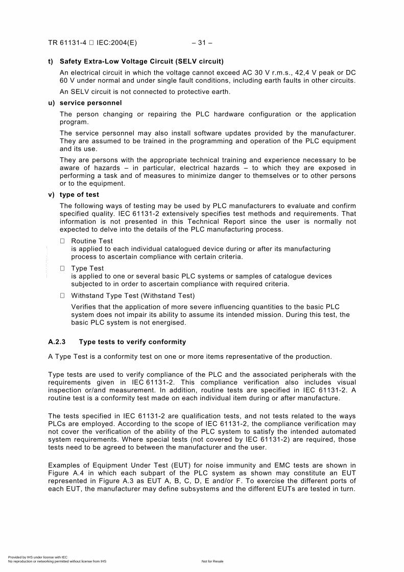
TR 61131-4 IEC:2004(E) – 31 –
t) Safety Extra-Low Voltage Circuit (SELV circuit) An electrical circuit in which the voltage cannot exceed AC 30 V r.m.s., 42,4 V peak or DC
60 V under normal and under single fault conditions, including earth faults in other circuits. An SELV circuit is not connected to protective earth. u) service personnel The person changing or repairing the PLC hardware configuration or the application
program. The service personnel may also install software updates provided by the manufacturer.
They are assumed to be trained in the programming and operation of the PLC equipment and its use.
They are persons with the appropriate technical training and experience necessary to be aware of hazards – in particular, electrical hazards – to which they are exposed in performing a task and of measures to minimize danger to themselves or to other persons or to the equipment.
v) type of test The following ways of testing may be used by PLC manufacturers to evaluate and confirm
specified quality. IEC 61131-2 extensively specifies test methods and requirements. That information is not presented in this Technical Report since the user is normally not expected to delve into the details of the PLC manufacturing process.
Routine Test is applied to each individual catalogued device during or after its manufacturing process to ascertain compliance with certain criteria.
Type Test is applied to one or several basic PLC systems or samples of catalogue devices subjected to in order to ascertain compliance with required criteria.
Withstand Type Test (Withstand Test) Verifies that the application of more severe influencing quantities to the basic PLC system does not impair its ability to assume its intended mission. During this test, the basic PLC system is not energised.
A.2.3 Type tests to verify conformity
A Type Test is a conformity test on one or more items representative of the production.
Type tests are used to verify compliance of the PLC and the associated peripherals with the requirements given in IEC 61131-2. This compliance verification also includes visual inspection or/and measurement. In addition, routine tests are specified in IEC 61131-2. A routine test is a conformity test made on each individual item during or after manufacture.
The tests specified in IEC 61131-2 are qualification tests, and not tests related to the ways PLCs are employed. According to the scope of IEC 61131-2, the compliance verification may not cover the verification of the ability of the PLC system to satisfy the intended automated system requirements. Where special tests (not covered by IEC 61131-2) are required, those tests need to be agreed to between the manufacturer and the user.
Examples of Equipment Under Test (EUT) for noise immunity and EMC tests are shown in Figure A.4 in which each subpart of the PLC system as shown may constitute an EUT represented in Figure A.3 as EUT A, B, C, D, E and/or F. To exercise the different ports of each EUT, the manufacturer may define subsystems and the different EUTs are tested in turn.
Copyright International Electrotechnical Commission Provided by IHS under license with IEC
Not for ResaleNo reproduction or networking permitted without license from IHS
--``````-`-`,,`,,`,`,,`---
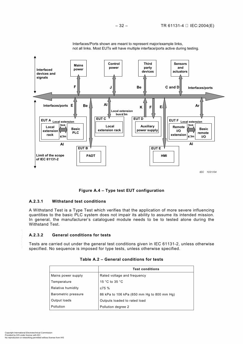
– 32 – TR 61131-4 IEC:2004(E)
Interfaces/ports
Mains power
Controlpower
EUT D
Auxiliarypower supply
EUT C
Localextension rack
Local extensionbus Local
extension rack
EUT A
Basic PLC
≤≤≤≤ 3m
Local extensionbus Remote
I/O extension
EUT F
Basicremote
I/O≤≤≤≤ 3m
Sensors and
actuators Thirdparty
devices
EUT E
HMI
EUT B PADT
Interfaces/ports Local extension
bus ≤≤≤≤ 3m
F J Be C and D
K FBe
Al Al
Al Ar EE
Limit of the scope of IEC 61131-2
Interfaced devices and signals
Interfaces/Ports shown are meant to represent major/example links, not all links. Most EUTs will have multiple interface/ports active during testing.
Figure A.4 – Type test EUT configuration
A.2.3.1 Withstand test conditions
A Withstand Test is a Type Test which verifies that the application of more severe influencing quantities to the basic PLC system does not impair its ability to assume its intended mission. In general, the manufacturer’s catalogued module needs to be to tested alone during the Withstand Test.
A.2.3.2 General conditions for tests
Tests are carried out under the general test conditions given in IEC 61131-2, unless otherwise specified. No sequence is imposed for type tests, unless otherwise specified.
Table A.2 – General conditions for tests
Test conditions
Mains power supply
Temperature
Relative humidity
Barometric pressure
Output loads
Pollution
Rated voltage and frequency
15 °C to 35 °C
≤75 %
86 kPa to 106 kPa (650 mm Hg to 800 mm Hg)
Outputs loaded to rated load
Pollution degree 2
IEC 1031/04
Copyright International Electrotechnical Commission Provided by IHS under license with IEC
Not for ResaleNo reproduction or networking permitted without license from IHS
--``````-`-`,,`,,`,`,,`---
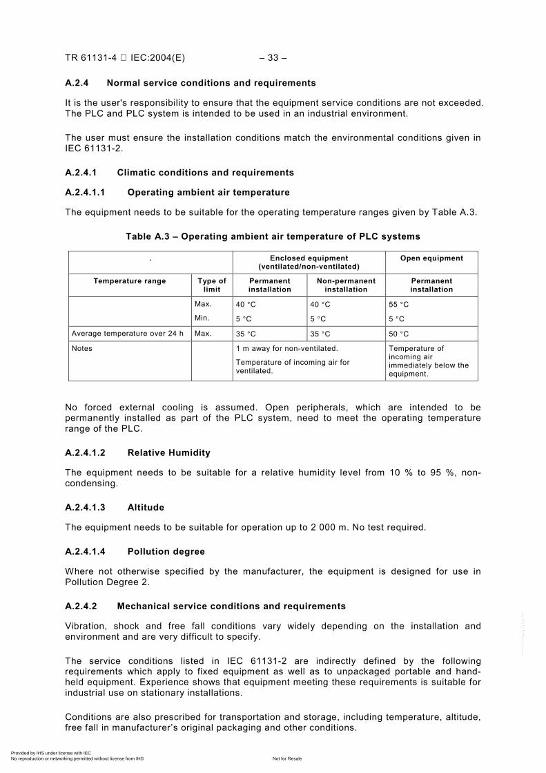
TR 61131-4 IEC:2004(E) – 33 –
A.2.4 Normal service conditions and requirements
It is the user's responsibility to ensure that the equipment service conditions are not exceeded. The PLC and PLC system is intended to be used in an industrial environment.
The user must ensure the installation conditions match the environmental conditions given in IEC 61131-2.
A.2.4.1 Climatic conditions and requirements
A.2.4.1.1 Operating ambient air temperature
The equipment needs to be suitable for the operating temperature ranges given by Table A.3.
Table A.3 – Operating ambient air temperature of PLC systems
. Enclosed equipment (ventilated/non-ventilated)
Open equipment
Temperature range Type of limit
Permanent installation
Non-permanent installation
Permanent installation
Max.
Min.
40 °C
5 °C
40 °C
5 °C
55 °C
5 °C
Average temperature over 24 h Max. 35 °C 35 °C 50 °C
Notes 1 m away for non-ventilated.
Temperature of incoming air for ventilated.
Temperature of incoming air immediately below the equipment.
No forced external cooling is assumed. Open peripherals, which are intended to be permanently installed as part of the PLC system, need to meet the operating temperature range of the PLC.
A.2.4.1.2 Relative Humidity
The equipment needs to be suitable for a relative humidity level from 10 % to 95 %, non-condensing.
A.2.4.1.3 Altitude
The equipment needs to be suitable for operation up to 2 000 m. No test required.
A.2.4.1.4 Pollution degree
Where not otherwise specified by the manufacturer, the equipment is designed for use in Pollution Degree 2.
A.2.4.2 Mechanical service conditions and requirements
Vibration, shock and free fall conditions vary widely depending on the installation and environment and are very difficult to specify.
The service conditions listed in IEC 61131-2 are indirectly defined by the following requirements which apply to fixed equipment as well as to unpackaged portable and hand-held equipment. Experience shows that equipment meeting these requirements is suitable for industrial use on stationary installations.
Conditions are also prescribed for transportation and storage, including temperature, altitude, free fall in manufacturer’s original packaging and other conditions.
Copyright International Electrotechnical Commission Provided by IHS under license with IEC
Not for ResaleNo reproduction or networking permitted without license from IHS
--``````-`-`,,`,,`,`,,`---
– 34 – TR 61131-4 IEC:2004(E)
A.2.4.3 Electrical service conditions and requirements
Electrical service conditions prescribed in IEC 61131-2 include: AC and DC mains power supply, overvoltage category, control of transient overvoltages, transient overvoltages at the point of connection to the mains power supply, non-periodic overvoltages.
The user needs to take the necessary steps to prevent damage to the PLC system (e.g. by interposing a transformer) under overvoltage conditions, in particular the very damaging nature of non-periodical overvoltage (spike) at the mains resulting from power interruption of high-energy circuit/equipment.
When the service conditions are more severe than those given in IEC 61131-2, or other adverse environmental conditions exist, (e.g. air pollution by dust, smoke, corrosive or radioactive particles, vapours or salts, attack by fungi, insects or small animals), the manufacturer should be consulted to determine suitability of the equipment or the steps to be taken.
A.2.5 Functional requirements
A.2.5.1 Functional power supply and memory power back-up requirements a) Rated value and operating range Incoming power supplies to the PLC system and to the externally powered I/O modules
are specified as:
Rated DC voltages are: 24 V, 48 V and 125 V with tolerance (min./max.) of –15 %/+20 %.
Rated AC r.m.s. voltages are: 24 V, 48 V, 100 V, 110 V, 120 V, 200 V, 230 V, 240 V, and 400 V with voltage tolerance of –15 %/+10 %. The specified frequencies are 50 Hz or 60 Hz. with tolerance (min./max.) of –6 %/+4 %.
AC voltage is in terms of the total r.m.s. voltage values measured at the point of entry to the equipment.
Total r.m.s. content of true harmonics (integral multiple of nominal frequency) less than 10 times nominal frequency may reach 10 % of the total voltage. Harmonic and other frequency content for higher frequencies may reach 2 % of the total voltage. However, to provide constant comparative results, the equipment needs to be tested at the third harmonic only (10 % at 0° and at 180° phase angle).
b) Memory power back-up Power back-up for volatile memories needs to be capable of maintaining stored
information for at least 300 h under normal use, and 1 000 h at a temperature not greater than 25 °C when the energy source is at rated capacity. (For power back-up needing replacement, the rated capacity is the value used to designate the procedure and time interval for replacement.)
The manufacturer is to specify storage time information relative to volatile memory if different from stated durations.
It should be possible to change or refresh power back-up without loss of data in the backed-up portions of memory. If a memory back-up battery is provided, a warning of “Low Battery Voltage” needs to be provided.
Copyright International Electrotechnical Commission Provided by IHS under license with IEC
Not for ResaleNo reproduction or networking permitted without license from IHS
--``````-`-`,,`,,`,`,,`---
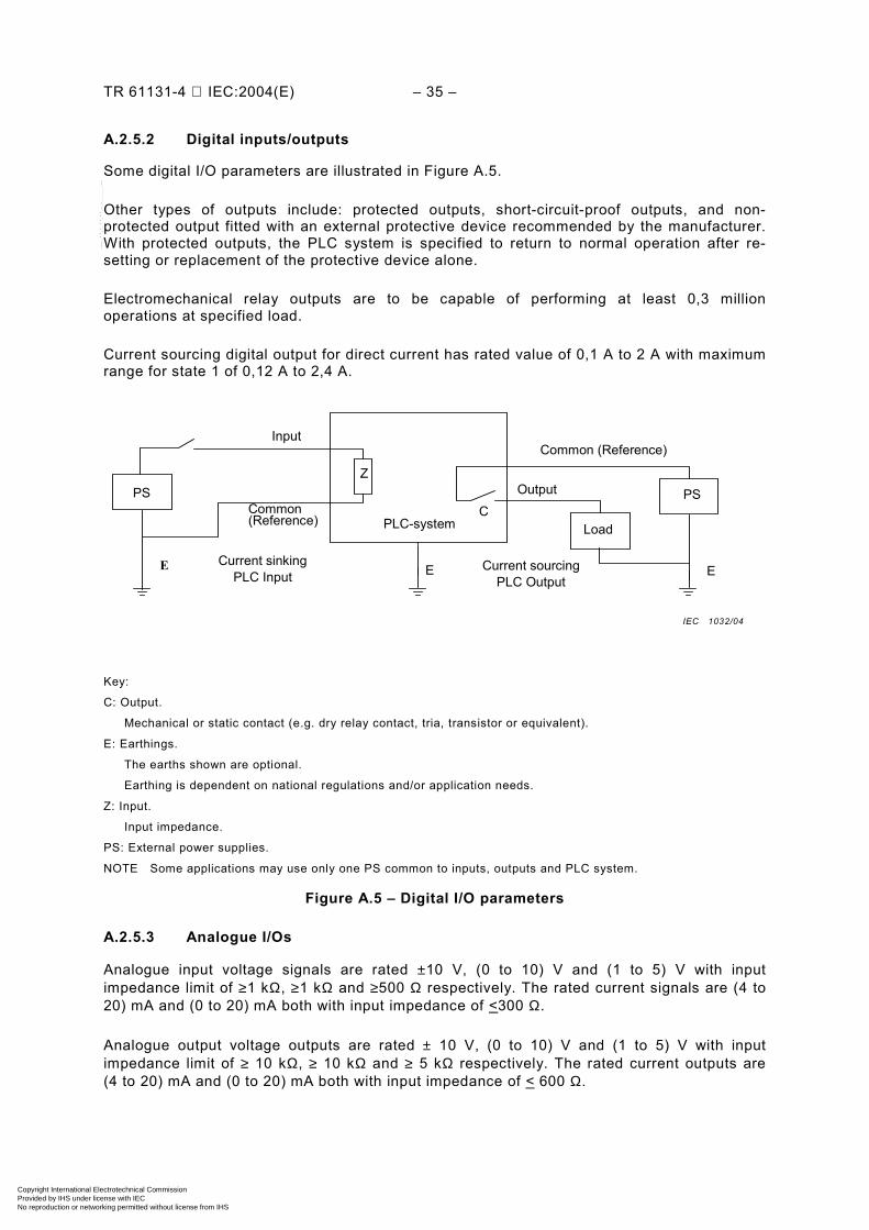
TR 61131-4 IEC:2004(E) – 35 –
A.2.5.2 Digital inputs/outputs
Some digital I/O parameters are illustrated in Figure A.5.
Other types of outputs include: protected outputs, short-circuit-proof outputs, and non-protected output fitted with an external protective device recommended by the manufacturer. With protected outputs, the PLC system is specified to return to normal operation after re-setting or replacement of the protective device alone.
Electromechanical relay outputs are to be capable of performing at least 0,3 million operations at specified load.
Current sourcing digital output for direct current has rated value of 0,1 A to 2 A with maximum range for state 1 of 0,12 A to 2,4 A.
Current sinking PLC Input Current sourcing
PLC Output
Input Common (Reference)
Common (Reference) PLC-system Load
PS PS
E E E
Z
C
Output
Key:
C: Output.
Mechanical or static contact (e.g. dry relay contact, tria, transistor or equivalent).
E: Earthings.
The earths shown are optional.
Earthing is dependent on national regulations and/or application needs.
Z: Input.
Input impedance.
PS: External power supplies.
NOTE Some applications may use only one PS common to inputs, outputs and PLC system.
Figure A.5 – Digital I/O parameters
A.2.5.3 Analogue I/Os
Analogue input voltage signals are rated ±10 V, (0 to 10) V and (1 to 5) V with input impedance limit of ≥1 kΩ, ≥1 kΩ and ≥500 Ω respectively. The rated current signals are (4 to 20) mA and (0 to 20) mA both with input impedance of <300 Ω.
Analogue output voltage outputs are rated ± 10 V, (0 to 10) V and (1 to 5) V with input impedance limit of ≥ 10 kΩ, ≥ 10 kΩ and ≥ 5 kΩ respectively. The rated current outputs are (4 to 20) mA and (0 to 20) mA both with input impedance of < 600 Ω.
IEC 1032/04
Copyright International Electrotechnical Commission Provided by IHS under license with IEC
Not for ResaleNo reproduction or networking permitted without license from IHS
--``````-`-`,,`,,`,`,,`---
– 36 – TR 61131-4 IEC:2004(E)
A.2.5.4 Remote Input/Output Stations (RIOSs) requirements
RIOSs are part of the permanent PLC installation and are therefore to be tested accordingly. In the case of loss of communication with the MPU application program, RIOSs are able to fix the states of their outputs to specified values, within specified delays and without passing through unspecified states and are capable of providing a fault indication signal. The MPU system needs to provide the user's application program with relevant information on current status of RIOSs.
A.2.5.5 Peripherals (PADTs, TEs, HMIs) requirements
Peripherals which are not a permanent part of the PLC system should not cause malfunction of the system when making or breaking communication with an operating system.
Connectors for the peripherals need to be polarized to prevent improper connection, or the PLC system needs to be so designed that no malfunction occurs if a connection is improper.
The system consisting of the peripheral and the PLC system needs to be designed to ensure that the edited program executing in the PLC system is functionally identical to the edited program displayed on the peripheral.
If on-line modification of the application program and/or the modes of operation of the PLC system by a peripheral is possible (i.e. when the PLC system is in active control of a machine or industrial process), then:
– The peripheral needs to automatically give clear warnings equivalent to "during on-line modification, program display may differ from application program, control of the machine/process may be interrupted during ... ms, etc.", as applicable.
– The peripheral needs to ask the operator "do you really want to carry out this action?" or some similar words and execute the command only after a positive reply has been given by the operator.
It has to be possible to upload the new application program to the manufacturer's supplied data media and verify, on-line, that the record is functionally equivalent to it, and means need to be provided to prevent unauthorized use of these functions (hardware or software).
A.2.5.6 PLC system self-tests and diagnostics requirements
The manufacturer needs to provide means of self-tests and diagnostics of the PLC system operation. Such means are built-in services of the PLC system, and/or recommended ways to implement the intended application.
The following need to be provided;
– a means for monitoring the user's application program (i.e. watchdog timer, etc.), – a hardware or software means to check the memory integrity, – a means to check the validity of the data exchanged between memory(ies), processing
unit(s) and I/O modules (such as an application loop-back test), – a means to check that the power supply unit(s) does not exceed the current and voltage
limits allowed by the hardware design, – a means to monitor the status of MPU.
The permanently installed PLC system needs to be capable of operating an alarm signal on an alarm output. When the system is monitored as “functioning correctly”, this alarm output shall be in a predetermined state; in the other case it shall go to the opposite state. The manufacturer needs to specify the conditions of the "correct functioning state" and the self-tests which are executed to drive this alarm output.
Copyright International Electrotechnical Commission Provided by IHS under license with IEC
Not for ResaleNo reproduction or networking permitted without license from IHS
--``````-`-`,,`,,`,`,,`---
TR 61131-4 IEC:2004(E) – 37 –
RIOSs need to be capable of operating an alarm signal on an alarm output (for example, through a digital output module) in the event of loss of power or loss of normal communication with the MPU and go to a predetermined state.
A.2.5.7 Other requirements
Other requirements prescribed in IEC 61131-2 include: functional earthing, mounting requirements, and general marking requirements.
For marking, functional earth terminals (i.e. used for non-safety purposes such as interference immunity improvement) are marked with the following symbol:
A.2.6 Normal service and function type tests and verification
IEC 61131-2 prescribes the following tests and verifications:
– climatic tests, mechanical tests; – shut-down test, start-up test;
- gradual shut-down/start-up test; – verification of special functional requirements for power ports and memory back-up;
- special Immunity limits for power ports; - verification of functional mains power port (AC or DC); - voltage range, ripple and frequency; - external energy supply variation tests (immunity tests); - supply voltage variation test; - Improper power supply connection tests; - reverse of DC power supply polarity test (withstand test); - improper voltage level and/or frequency test;
– verification of memory back-up requirements; – verification of input/output requirements; – verification of digital inputs; – operating range test; – reversal of signal polarity test (withstand test); – verification of digital outputs, including:
- operating range test, - test of protected not-protected, - short-circuit proof outputs, and - reversal of signal polarity;
– verification of analogue I/Os, including: - operating range test, - analogue input overload withstand test, - short-circuit test (voltage output), and - open-circuit test (current output); NOTE No physical damage or abnormal phenomenon should be detected. Functional verification is performed after the tests, voltage supply variation test and reversal of signal polarity test (withstand test).
Copyright International Electrotechnical Commission Provided by IHS under license with IEC
Not for ResaleNo reproduction or networking permitted without license from IHS
--``````-`-`,,`,,`,`,,`---
– 38 – TR 61131-4 IEC:2004(E)
– verification of remote I/O station, including: - response time test; - loss of communication test;
– verification of peripherals (PADTs, TEs, HMIs) requirements; – verification of PLC system self-tests and diagnostics; – verification of markings and manufacturer’s documentation.
A.2.7 Equipment information to be provided by the manufacturer
A.2.7.1 Information on type and content of documentation
A.2.7.1.1 Information on catalogues and datasheets
These documents need to contain the description and the specifications of the PLC system and its associated peripherals. Additionally, they need to contain any other relevant information to aid in understanding the application and use of these products including functional characteristics, equipment configuration rules, normal service conditions, physical dimensions and weights, and list compliance with standards and certifications.
A.2.7.1.2 Information on user's manuals
These documents include the necessary information for the proper installation, wiring, troubleshooting, user programming and commissioning of the PLC system by the user. They are to include as a minimum:
– installation and commissioning instructions; – programming and troubleshooting instructions; – maintenance and service requirements, and – accessory and spare parts lists (e.g. fuses).
A.2.7.1.3 Information on technical documentation
The manufacturer may optionally provide a set of documents which contain more information than those given in the users manual such as: schematic diagrams, internal or external data protocols, bus assignments, physical dimension characteristics, energy available, firmware, internal test programs or repair procedures, etc.
A.2.7.2 Information on compliance with this standard
The manufacturer needs to provide information on compliance with IEC 61131-2, which can be claimed on two levels:
a) full compliance with all of the requirements contained in all clauses of the standard, such as indicated by reference to IEC 61131-2 without qualification;
b) compliance with a portion of the standard where documentation identifies the specific clauses of the standard with which the product has been determined to comply.
A.2.7.3 Information on reliability
If the manufacturer provides values of the Mean Time Between Failures (MTBF) of any subassembly or module, and of the type-test configuration (s) (PLC system (s)) under normal service conditions the manufacturer also needs to explain the method used to determine it.
A.2.7.4 Information on other conditions
The user is to reach agreement with the manufacturer for any mechanical conditions that are not specified in IEC 61131-2.
Copyright International Electrotechnical Commission Provided by IHS under license with IEC
Not for ResaleNo reproduction or networking permitted without license from IHS
--``````-`-`,,`,,`,`,,`---
TR 61131-4 IEC:2004(E) – 39 –
A.2.7.5 Information on shipping and storage
The manufacturer provides shipping and storing instructions.
A.2.7.6 Information on AC and DC power supply
The manufacturer is to provide the following information:
– data to allow selection of a suitable power distribution network to provide specified voltage at each power utilization point. This information includes peak inrush (at cold start and warm restart), repetitive peak and steady-state r.m.s. input currents under full load conditions;
– external terminal identification for power supply interfaces; – typical example(s) for power supply system(s); – special supply installation requirements, if any, for PLC systems energized through
multiple power supplies or supply voltages and frequencies not included in IEC 61131-2; – the effect of the following incorrect connections of power to the supply(ies): reverse
polarity, improper voltage level and/or frequency and improper lead connection; – complete information on PLC system behaviour for typical power up/down sequences; – data to allow evaluation of the maximum values of interruption time which do not affect the
normal operation of any PLC system configuration; PS class (PS-1 or PS-2) of DC supplied devices;
– memory back-up time with respect to temperature and maintenance requirements; – recommended time interval between replacement of energy sources, if applicable, and
recommended procedure and subsequent effects on the PLC system; – peak inrush current (at cold start and warm restart) or recommended fuse size and
blowing characteristics.
A.2.7.7 Information on digital inputs (current sinking)
The manufacturer is to provide the following information:
– volt-ampere curve over the full-operating range, with tolerances or equivalent; – digital input delay time for 0 to 1 and 1 to 0 transitions; – existence of common points between channels; – effect of incorrect input terminal connection; – isolation potentials between channel and other circuits (including ground) and between
channels under normal operation; – type of input (Type 1, Type 2 or Type 3); – monitoring point and binary state of visual indicator; – effects when withdrawing/inserting input module under power; – additional external load when interconnecting inputs and outputs, if needed; – explanation of signal evaluation (for example static/dynamic evaluation, interrupt release,
etc.); – recommended cable and cord lengths depending on cable type and electromagnetic
compatibility; – terminal arrangements; – typical example(s) of external connections.
Copyright International Electrotechnical Commission Provided by IHS under license with IEC
Not for ResaleNo reproduction or networking permitted without license from IHS
--``````-`-`,,`,,`,`,,`---
– 40 – TR 61131-4 IEC:2004(E)
A.2.7.8 Information on digital outputs for alternating currents (current sourcing) The manufacturer is to provide the following information with respect to digital outputs for AC operation:
– type of protection (i.e. protected, short-circuit proof, not-protected output) and: - for protected outputs: operating characteristics beyond 1,1 rated current including the
current(s) level(s) at which the protecting device energizes, the current behaviour beyond, and the time(s) involved;
- for short-circuit proof outputs: information for replacement or resetting the protective device as required;
- for not-protected outputs: specification for protective device to be provided by the user, as required;
– output delay time for state 0 to state 1 and state 1 to state 0 transitions; – commutation characteristics and turn-on voltage with respect to zero voltage crossing; – existence of common points between channels; – terminal arrangements; – typical example(s) of external connections; – number and type of outputs (e.g. NO/NC contacts, solid state, individually isolated
channels, etc.); – for electromechanical relays, the rated current and voltage complying with IEC 61131-2; – output ratings for the other loads such as incandescent lamps; – total output current for multi-channel modules; – characteristics of suppresser networks incorporated into the output circuit against
voltage peaks due to inductive kickback; – type of external protective networks, if required; – effects of incorrect output terminal connection; – isolation potentials between channel and other circuits (including ground) and between
channels under normal operation; – monitoring points of visual indicators in the channel (e.g. MPU side/load side); – recommended procedures for changing output modules; – output behaviour during interruptions of MPU control, voltage drops and interruptions and
power up/down sequences; – type of operation (i.e. latching/non-latching type); – effects of multiple overloads on isolated multi-channel modules.
A.2.7.9 Information on digital outputs for direct current (current sourcing)
The information to be provided by the manufacturer for digital outputs for DC is the same as for digital outputs for AC. However, the specification of commutation for zero voltage crossing does not apply, and with regard to electromechanical relay outputs.
Copyright International Electrotechnical Commission Provided by IHS under license with IEC
Not for ResaleNo reproduction or networking permitted without license from IHS
--``````-`-`,,`,,`,`,,`---
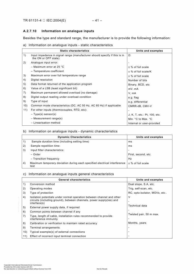
TR 61131-4 IEC:2004(E) – 41 –
A.2.7.10 Information on analogue inputs
Besides the type and standard range, the manufacturer is to provide the following information:
a) Information on analogue inputs - static characteristics
Static characteristics Units and examples 1) Input impedance in signal range (manufacturer should specify if this is in
the ON or OFF state) 2) Analogue input error: – Maximum error at 25 °C – Temperature coefficient 3) Maximum error over full temperature range 4) Digital resolution 5) Data format returned of the application program 6) Value of a LSB (least significant bit) 7) Maximum permanent allowed overload (no damage) 8) Digital output reading under overload condition 9) Type of input 10) Common mode characteristics (DC, AC 50 Hz, AC 60 Hz) if applicable 11) For other inputs (thermocouples, RTD, etc): – Type(s) sensor(s) – Measurement range(s) – Linearisation method
Ω -
± % of full scale
± % of full scale/K
± % of full scale Number of bits Binary, BCD, etc mV, mA V, mA e.g. flag e.g. differential CMRR-dB, CMV-V - J, K, T, etc.: Pt, 100, etc. Min. °C to Max. °C Internal or user-provided
b) Information on analogue inputs - dynamic characteristics
Dynamic Characteristics Units and examples 1) Sample duration time (including setting time) 2) Sample repetition time 3) Input filter characteristics: – Order – Transition frequency 4) Maximum temporary deviation during each specified electrical interference
test
ms ms - First, second, etc. Hz
± % of full scale
c) Information on analogue inputs general characteristics
General characteristics Units and examples 1) Conversion method 2) Operating modes 3) Type of protection 4) Isolation potentials under normal operation between channel and other
circuits (including ground), between channels, power supply(ies) and interface(s)
5) External power supply data, if required 6) Common points between channel if any 7) Type, length of cable, installation rules recommended to provide
interference immunity 8) Calibration or verification to maintain rated accuracy 9) Terminal arrangements 10) Typical example(s) of external connections 11) Effect of incorrect input terminal connection
Dual slope, S.A, etc. Trig, self-scan, etc. RC, opto-isolator, MOVs, etc.. V - Technical data - Twisted pair, 50 m max. - Months, years - - -
Copyright International Electrotechnical Commission Provided by IHS under license with IEC
Not for ResaleNo reproduction or networking permitted without license from IHS
--``````-`-`,,`,,`,`,,`---
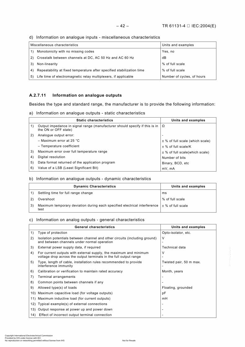
– 42 – TR 61131-4 IEC:2004(E)
d) Information on analogue inputs - miscellaneous characteristics
Miscellaneous characteristics Units and examples
1) Monotonicity with no missing codes
2) Crosstalk between channels at DC, AC 50 Hz and AC 60 Hz
3) Non-linearity
4) Repeatability at fixed temperature after specified stabilization time
5) Life time of electromagnetic relay multiplexers, if applicable
Yes, no
dB
% of full scale
% of full scale
Number of cycles, of hours
A.2.7.11 Information on analogue outputs
Besides the type and standard range, the manufacturer is to provide the following information:
a) Information on analogue outputs - static characteristics
Static characteristics Units and examples 1) Output impedance in signal range (manufacturer should specify if this is in
the ON or OFF state) 2) Analogue output error: – Maximum error at 25 °C – Temperature coefficient 3) Maximum error over full temperature range 4) Digital resolution 5) Data format returned of the application program 6) Value of a LSB (Least Significant Bit)
Ω -
± % of full scale (which scale)
± % of full scale/K
± % of full scale(which scale) Number of bits Binary, BCD, etc mV, mA
b) Information on analogue outputs - dynamic characteristics
Dynamic Characteristics Units and examples
1) Settling time for full range change
2) Overshoot
3) Maximum temporary deviation during each specified electrical interference test
ms
% of full scale
± % of full scale
c) Information on analog outputs - general characteristics
General characteristics Units and examples 1) Type of protection 2) Isolation potentials between channel and other circuits (including ground)
and between channels under normal operation 3) External power supply data, if required 4) For current outputs with external supply, the maximum and minimum
voltage drop across the output terminals in the full output range 5) Type, length of cable, installation rules recommended to provide
interference immunity 6) Calibration or verification to maintain rated accuracy 7) Terminal arrangements 8) Common points between channels if any 9) Allowed type(s) of loads 10) Maximum capacitive load (for voltage outputs) 11) Maximum inductive load (for current outputs) 12) Typical example(s) of external connections 13) Output response at power up and power down 14) Effect of incorrect output terminal connection
Opto-isolator, etc. V - Technical data V - Twisted pair, 50 m max. - Month, years - - Floating, grounded pF mH - - -
Copyright International Electrotechnical Commission Provided by IHS under license with IEC
Not for ResaleNo reproduction or networking permitted without license from IHS
--``````-`-`,,`,,`,`,,`---
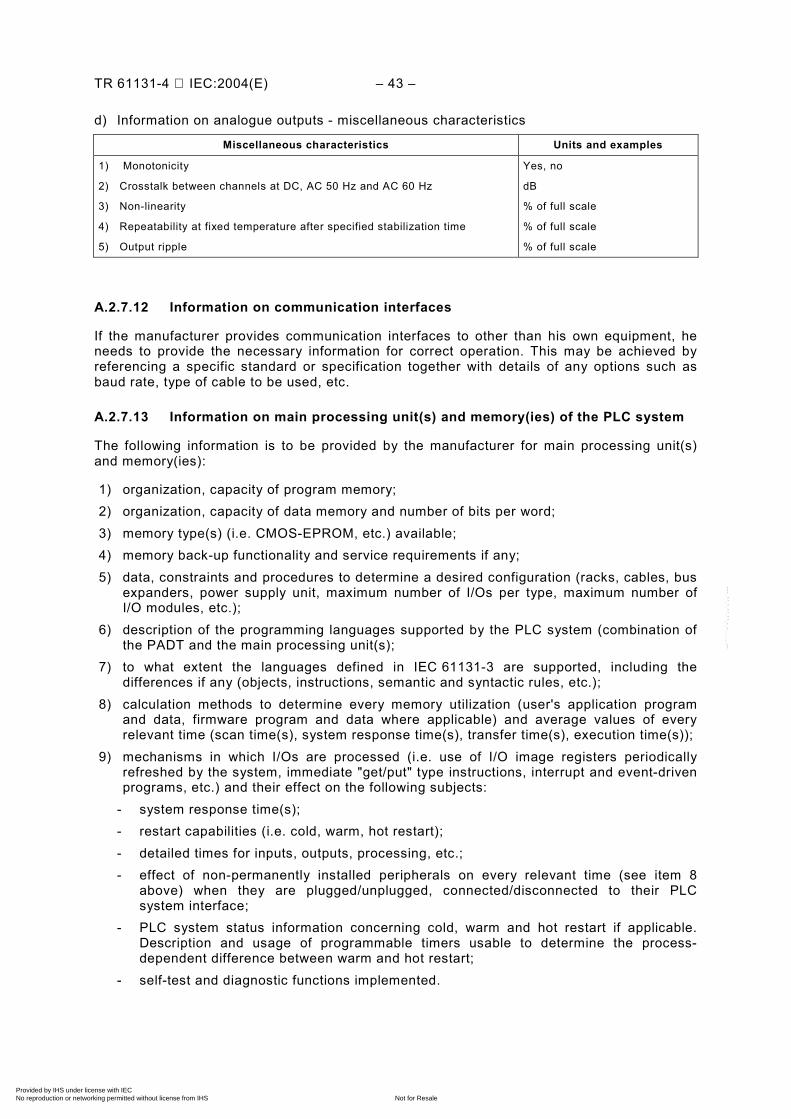
TR 61131-4 IEC:2004(E) – 43 –
d) Information on analogue outputs - miscellaneous characteristics
Miscellaneous characteristics Units and examples
1) Monotonicity
2) Crosstalk between channels at DC, AC 50 Hz and AC 60 Hz
3) Non-linearity
4) Repeatability at fixed temperature after specified stabilization time
5) Output ripple
Yes, no
dB
% of full scale
% of full scale
% of full scale
A.2.7.12 Information on communication interfaces
If the manufacturer provides communication interfaces to other than his own equipment, he needs to provide the necessary information for correct operation. This may be achieved by referencing a specific standard or specification together with details of any options such as baud rate, type of cable to be used, etc.
A.2.7.13 Information on main processing unit(s) and memory(ies) of the PLC system
The following information is to be provided by the manufacturer for main processing unit(s) and memory(ies):
1) organization, capacity of program memory; 2) organization, capacity of data memory and number of bits per word; 3) memory type(s) (i.e. CMOS-EPROM, etc.) available; 4) memory back-up functionality and service requirements if any; 5) data, constraints and procedures to determine a desired configuration (racks, cables, bus
expanders, power supply unit, maximum number of I/Os per type, maximum number of I/O modules, etc.);
6) description of the programming languages supported by the PLC system (combination of the PADT and the main processing unit(s);
7) to what extent the languages defined in IEC 61131-3 are supported, including the differences if any (objects, instructions, semantic and syntactic rules, etc.);
8) calculation methods to determine every memory utilization (user's application program and data, firmware program and data where applicable) and average values of every relevant time (scan time(s), system response time(s), transfer time(s), execution time(s));
9) mechanisms in which I/Os are processed (i.e. use of I/O image registers periodically refreshed by the system, immediate "get/put" type instructions, interrupt and event-driven programs, etc.) and their effect on the following subjects:
- system response time(s); - restart capabilities (i.e. cold, warm, hot restart); - detailed times for inputs, outputs, processing, etc.; - effect of non-permanently installed peripherals on every relevant time (see item 8
above) when they are plugged/unplugged, connected/disconnected to their PLC system interface;
- PLC system status information concerning cold, warm and hot restart if applicable. Description and usage of programmable timers usable to determine the process-dependent difference between warm and hot restart;
- self-test and diagnostic functions implemented.
Copyright International Electrotechnical Commission Provided by IHS under license with IEC
Not for ResaleNo reproduction or networking permitted without license from IHS
--``````-`-`,,`,,`,`,,`---
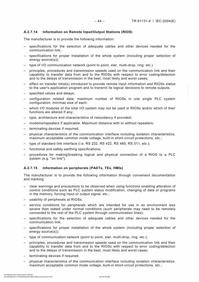
– 44 – TR 61131-4 IEC:2004(E)
A.2.7.14 Information on Remote Input/Output Stations (RIOS)
The manufacturer is to provide the following information:
– specifications for the selection of adequate cables and other devices needed for the communication link;
– specifications for proper installation of the whole system (including proper selection of energy source(s));
– type of I/O communication network (point to point, star, multi-drop, ring, etc.) – principles, procedures and transmission speeds used on the communication link and their
capability to transfer data from and to the RIOSs with respect to error coding/detection and to the delays of transmission in the best, most likely and worst cases;
– effect on transfer time(s) introduced to provide remote input information and RIOSs status to the user's application program and to transmit its logical decisions to remote outputs;
– specified values and delays; – configuration related data: maximum number of RIOSs in one single PLC system
configuration, min/max size of each; – which I/O modules of the total I/O system may not be used in RIOSs and/or which of their
functions are altered if any; – type, architecture and characteristics of redundancy if provided; – modems/repeaters if applicable. Maximum distance with or without repeaters; – terminating devices if required; – physical characteristics of the communication interface including isolation characteristics,
maximum acceptable common mode voltage, built-in short-circuit protections, etc.; – type of standard link interface (i.e. RS 232, RS 422, RS 485, RS 511, etc.); – functional and safety earthing specifications; – procedures for making/breaking logical and physical connection of a RIOS to a PLC
system (e.g. "on line").
A.2.7.15 Information on peripherals (PADTs, TEs, HMIs)
The manufacturer is to provide the following information through convenient documentation and marking:
– clear warnings and precautions to be observed when using functions enabling alteration of control conditions such as PLC system status modification, changing of data or programs in the memory, forcing input or output signal, etc.;
– usability of peripherals at RIOSs; – service conditions for peripherals which are intended for use in an environment less
severe than stated under normal conditions (such peripherals may need to be remotely connected to the rest of the PLC system through communication lines);
– specifications for the selection of adequate cables and other devices needed for the communication link;
– specifications for proper installation of the whole system (including proper selection of energy source(s));
– type of communication network (point to point, star, multi-drop, ring, etc.); – principles, procedures and transmission speeds used on the communication link and their
capability to transfer data from and to the RIOSs with respect to error coding/detection and to the delays of transmission in the best, most likely and worst cases;
– terminating devices if required; – physical characteristics of the communication interface including isolation characteristics,
maximum acceptable common mode voltage, built-in short-circuit protections, etc.;
Copyright International Electrotechnical Commission Provided by IHS under license with IEC
Not for ResaleNo reproduction or networking permitted without license from IHS
--``````-`-`,,`,,`,`,,`---
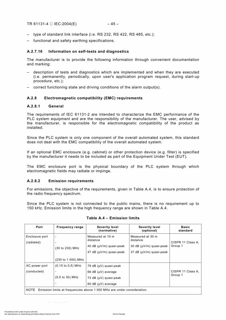
TR 61131-4 IEC:2004(E) – 45 –
– type of standard link interface (i.e. RS 232, RS 422, RS 485, etc.); – functional and safety earthing specifications.
A.2.7.16 Information on self-tests and diagnostics
The manufacturer is to provide the following information through convenient documentation and marking:
– description of tests and diagnostics which are implemented and when they are executed (i.e. permanently, periodically, upon user's application program request, during start-up procedure, etc.);
– correct functioning state and driving conditions of the alarm output(s).
A.2.8 Electromagnetic compatibility (EMC) requirements
A.2.8.1 General
The requirements of IEC 61131-2 are intended to characterize the EMC performance of the PLC system equipment and are the responsibility of the manufacturer. The user, advised by the manufacturer, is responsible for the electromagnetic compatibility of the product as installed.
Since the PLC system is only one component of the overall automated system, this standard does not deal with the EMC compatibility of the overall automated system.
If an optional EMC enclosure (e.g. cabinet) or other protection device (e.g. filter) is specified by the manufacturer it needs to be included as part of the Equipment Under Test (EUT).
The EMC enclosure port is the physical boundary of the PLC system through which electromagnetic fields may radiate or impinge.
A.2.8.2 Emission requirements
For emissions, the objective of the requirements, given in Table A.4, is to ensure protection of the radio frequency spectrum.
Since the PLC system is not connected to the public mains, there is no requirement up to 150 kHz. Emission limits in the high frequency range are shown in Table A.4.
Table A.4 – Emission limits
Port Frequency range Severity level (normative)
Severity level (optional)
Basic standard
Enclosure port
(radiated)
-
-
(30 to 230) MHz
(230 to 1 000) MHz
Measured at 10 m distance
40 dB (µV/m) quasi-peak
47 dB (µV/m) quasi-peak
Measured at 30 m distance
30 dB (µV/m) quasi-peak
37 dB (µV/m) quasi-peak
CISPR 11 Class A, Group 1
AC power port
(conducted)
(0,15 to 0,5) MHz
-
(0,5 to 30) MHz
-
79 dB (µV) quasi-peak
66 dB (µV) average
73 dB (µV) quasi-peak
60 dB (µV) average
CISPR 11 Class A, Group 1
NOTE Emission limits at frequencies above 1 000 MHz are under consideration.
Copyright International Electrotechnical Commission Provided by IHS under license with IEC
Not for ResaleNo reproduction or networking permitted without license from IHS
--``````-`-`,,`,,`,`,,`---
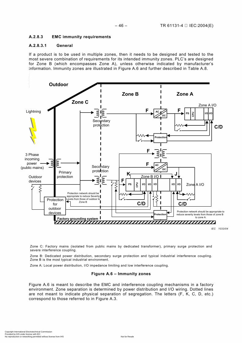
– 46 – TR 61131-4 IEC:2004(E)
A.2.8.3 EMC immunity requirements
A.2.8.3.1 General
If a product is to be used in multiple zones, then it needs to be designed and tested to the most severe combination of requirements for its intended immunity zones. PLC’s are designed for Zone B (which encompasses Zone A), unless otherwise indicated by manufacturer’s information. Immunity zones are illustrated in Figure A.6 and further described in Table A.8.
ACDCPS
CPU
I/OI/O
Zone C
Zone A Zone B
Lightning
Primaryprotection
Protection for
outdoor devices
3 Phase incoming
power (public mains)
Secondaryprotection
PS
CPU
I/O I/O I/O
AC
DC
Protection
Outdoor devices
Outdoor
Zone A I/O
Zone A I/O
Zone B I/O
I/O
Protection
I/O
Secondaryprotection K J
F
F
C/D
F
C/D C/D
AC
F
F
Factory grounding system Protection network should be appropriate toreduce severity levels from those of zone B
to zone A.
Protection network should be appropriate to reduce Severity Levels from those of outdoor to
Zone B
Zone C: Factory mains (isolated from public mains by dedicated transformer), primary surge protection and severe interference coupling.
Zone B: Dedicated power distribution, secondary surge protection and typical industrial interference coupling. Zone B is the most typical industrial environment.
Zone A: Local power distribution, I/O impedance limiting and low interference coupling.
Figure A.6 – Immunity zones
Figure A.6 is meant to describe the EMC and interference coupling mechanisms in a factory environment. Zone separation is determined by power distribution and I/O wiring. Dotted lines are not meant to indicate physical separation of segregation. The letters (F, K, C, D, etc.) correspond to those referred to in Figure A.3.
IEC 1033/04
Copyright International Electrotechnical Commission Provided by IHS under license with IEC
Not for ResaleNo reproduction or networking permitted without license from IHS
--``````-`-`,,`,,`,`,,`---
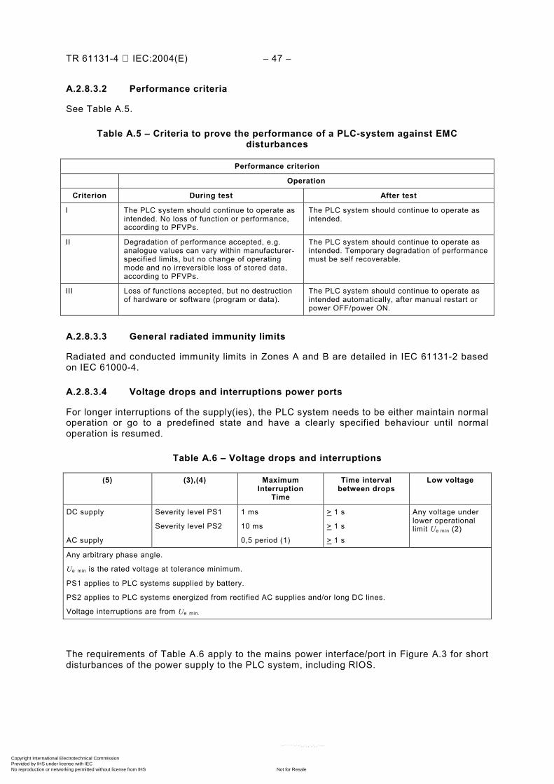
TR 61131-4 IEC:2004(E) – 47 –
A.2.8.3.2 Performance criteria
See Table A.5.
Table A.5 – Criteria to prove the performance of a PLC-system against EMC disturbances
Performance criterion
Operation
Criterion During test After test
I The PLC system should continue to operate as intended. No loss of function or performance, according to PFVPs.
The PLC system should continue to operate as intended.
II Degradation of performance accepted, e.g. analogue values can vary within manufacturer-specified limits, but no change of operating mode and no irreversible loss of stored data, according to PFVPs.
The PLC system should continue to operate as intended. Temporary degradation of performance must be self recoverable.
III Loss of functions accepted, but no destruction of hardware or software (program or data).
The PLC system should continue to operate as intended automatically, after manual restart or power OFF/power ON.
A.2.8.3.3 General radiated immunity limits
Radiated and conducted immunity limits in Zones A and B are detailed in IEC 61131-2 based on IEC 61000-4.
A.2.8.3.4 Voltage drops and interruptions power ports
For longer interruptions of the supply(ies), the PLC system needs to be either maintain normal operation or go to a predefined state and have a clearly specified behaviour until normal operation is resumed.
Table A.6 – Voltage drops and interruptions
(5) (3),(4) Maximum Interruption
Time
Time interval between drops
Low voltage
DC supply
AC supply
Severity level PS1
Severity level PS2
1 ms
10 ms
0,5 period (1)
> 1 s
> 1 s
> 1 s
Any voltage under lower operational limit Ue min (2)
Any arbitrary phase angle.
Ue min is the rated voltage at tolerance minimum.
PS1 applies to PLC systems supplied by battery.
PS2 applies to PLC systems energized from rectified AC supplies and/or long DC lines.
Voltage interruptions are from Ue min.
The requirements of Table A.6 apply to the mains power interface/port in Figure A.3 for short disturbances of the power supply to the PLC system, including RIOS.
Copyright International Electrotechnical Commission Provided by IHS under license with IEC
Not for ResaleNo reproduction or networking permitted without license from IHS
--``````-`-`,,`,,`,`,,`---
– 48 – TR 61131-4 IEC:2004(E)
A.2.9 Electromagnetic compatibility (EMC) type tests and verification
The following tests and verifications are detailed in IEC 61131-2:
– EMC related tests; – test environment; – measurement of radiated interference; – measurement of conducted interference; – electrostatic discharge; – radio frequency electromagnetic field – amplitude modulated; – power frequency magnetic fields; – fast transient bursts; – high energy surge immunity; – conducted radio frequency interference immunity; – damped oscillatory wave immunity (for Zone C only); – voltage drop and interruptions immunity – power port type test and verification.
A.2.10 EMC information to be provided by the manufacturer
Information to be made available can be in other than printed form.
General rules of installation are as noted in IEC 61131-4. Specific installation information needs to be provided by the manufacturer.
The manufacturer needs to state if its devices are intended to be used under normal service conditions or in a less severe environment (e.g. office environment). If the PLC is intended for other than Zone B (which encompasses Zone A), the manufacturer needs to state the intended zone.
The Test Report needs to describe all the tests, the rationale for the selection of the typical (representative) configuration of the EUT and the test results. The EUT software during the test is to be documented.
A.2.11 Safety requirements
The PLC safety clauses in IEC 61131-2 has two main subjects: protection against electrical shock and protection against the spread of fire. IEC 61131-2 specifies the design, material and testing methods to meet the safety requirements.
A.2.11.1 Protection against electrical shock
Protection against electric shock of the PLC system is maintained in normal and single fault conditions. Accessible parts of equipment should not be, or become, hazardous live.
Protection is provided by compliance with dielectric strength, operator accessibility, normal condition, single fault and clearance and creepage requirements in IEC 61131-2.
A.2.11.1.1 Permissible limits for accessible parts
To ensure that accessible parts are not hazardous live, the voltage, current, charge or energy between an accessible part and reference test earth, or between any two accessible parts on the same piece of equipment within a distance of 1,8 m (over a surface or through air) are specified in IEC 61131-2.
Copyright International Electrotechnical Commission Provided by IHS under license with IEC
Not for ResaleNo reproduction or networking permitted without license from IHS
--``````-`-`,,`,,`,`,,`---
TR 61131-4 IEC:2004(E) – 49 –
a) Values in normal conditions Hazardous live conditions are voltage values above AC 30 V r.m.s. and 42,4 V peak or DC
60 V. b) Value in single-fault conditions In single fault conditions, voltage values above AC 50 V r.m.s. and 70 V peak or DC 20 V
are deemed hazardous live.
A.2.11.1.2 Open PLC system equipment
Open PLC system equipment is equipment that may have live electrical parts accessible, e.g. a main processing unit. Protection against electric shock needs to be provided for those interfaces that are so classified in A.2.11.1.5. Open equipment is to be incorporated into other assemblies manufactured to provide safety.
A.2.11.1.3 Enclosed PLC system equipment
Enclosed PLC system equipment is equipment which is enclosed on all sides, with the possible exception of its mounting surface, to prevent personnel from accidentally touching live or moving parts contained therein, to protect the equipment against ingress of 12,5 mm diameter and greater solid foreign bodies, and meeting requirements of mechanical strength, flammability, and stability (where applicable). Protection degree must be ≥IP20 as per IEC 60529.
Protection against electric shock needs to be provided for those interfaces that are classified as in A.2.11.1.5. Each entity of an enclosed PLC system needs to comply with the requirements of Equipment Classes I, II or III. The protection degree is ≥IP20. The protective earthing conductor is a part of a flexible cord set.
A.2.11.1.4 Dielectric strength type test
The dielectric withstand type test is detailed in IEC 61131-2 between all parts and circuits where basic, reinforced or double insulation are specified for protection against electric shock.
A.2.11.1.5 Operator accessibility
Table A.7 defines ports of a PLC system requiring protection against shock. Under special circumstances, some ports of either open or enclosed equipment may or may not be considered operator accessible. This is to be agreed upon between the manufacturer and the user.
Copyright International Electrotechnical Commission Provided by IHS under license with IEC
Not for ResaleNo reproduction or networking permitted without license from IHS
--``````-`-`,,`,,`,`,,`---
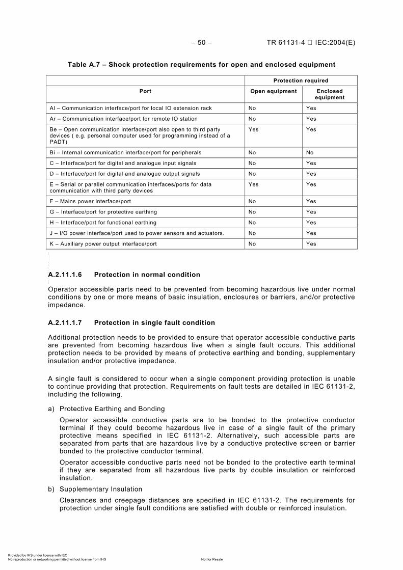
– 50 – TR 61131-4 IEC:2004(E)
Table A.7 – Shock protection requirements for open and enclosed equipment
Protection required
Port Open equipment Enclosed equipment
Al – Communication interface/port for local IO extension rack No Yes
Ar – Communication interface/port for remote IO station No Yes
Be – Open communication interface/port also open to third party devices ( e.g. personal computer used for programming instead of a PADT)
Yes Yes
Bi – Internal communication interface/port for peripherals No No
C – Interface/port for digital and analogue input signals No Yes
D – Interface/port for digital and analogue output signals No Yes
E – Serial or parallel communication interfaces/ports for data communication with third party devices
Yes Yes
F – Mains power interface/port No Yes
G – Interface/port for protective earthing No Yes
H – Interface/port for functional earthing No Yes
J – I/O power interface/port used to power sensors and actuators. No Yes
K – Auxiliary power output interface/port No Yes
A.2.11.1.6 Protection in normal condition
Operator accessible parts need to be prevented from becoming hazardous live under normal conditions by one or more means of basic insulation, enclosures or barriers, and/or protective impedance.
A.2.11.1.7 Protection in single fault condition
Additional protection needs to be provided to ensure that operator accessible conductive parts are prevented from becoming hazardous live when a single fault occurs. This additional protection needs to be provided by means of protective earthing and bonding, supplementary insulation and/or protective impedance.
A single fault is considered to occur when a single component providing protection is unable to continue providing that protection. Requirements on fault tests are detailed in IEC 61131-2, including the following.
a) Protective Earthing and Bonding Operator accessible conductive parts are to be bonded to the protective conductor
terminal if they could become hazardous live in case of a single fault of the primary protective means specified in IEC 61131-2. Alternatively, such accessible parts are separated from parts that are hazardous live by a conductive protective screen or barrier bonded to the protective conductor terminal.
Operator accessible conductive parts need not be bonded to the protective earth terminal if they are separated from all hazardous live parts by double insulation or reinforced insulation.
b) Supplementary Insulation Clearances and creepage distances are specified in IEC 61131-2. The requirements for
protection under single fault conditions are satisfied with double or reinforced insulation.
Copyright International Electrotechnical Commission Provided by IHS under license with IEC
Not for ResaleNo reproduction or networking permitted without license from IHS
--``````-`-`,,`,,`,`,,`---

TR 61131-4 IEC:2004(E) – 51 –
c) Protective Impedance The protective impedance needs to limit the voltage from becoming hazardous live under
normal or single fault conditions on operator accessible parts or to values for SELV. The use of a single component not liable to become defective in such a manner as to cause a risk of hazard is allowed. Verification of these requirements is specified in IEC 61131-2.
A.2.11.2 Protection against the spread of fire
Protection against the spread of fire is to be evaluated between limited power circuits and other circuits. There are no requirements for protection against the spread of fire within limited power circuits.
If limited power circuits are not employed, all other requirements of IEC 61131-2 for the protection against the spread of fire are to be met. Where breakdown of components is involved, compliance is to be verified.
A.2.11.3 Limited power circuits
A limited power circuit is a circuit supplied by sources such as a battery or a transformer winding where the open-circuit potential is not more than AC 30 V r.m.s. and 42,4 V peak or DC 60 V, and the energy available to the circuit is limited according to one of the following means:
– the maximum output current and power are inherently limited and specified in IEC 61131-2; – the maximum output current under all conditions and power are limited by impedance to
below the limits set in IEC 61131-2; – an over-current protective device limits the maximum output current and power to below
the limits set by IEC 61131-2; – a regulating network limits the maximum output current and power to those set by
IEC 61131-2; – a regulating network limits the maximum output current and power as the result of any one
fault in the regulating network set by IEC 61131-2.
Where an over-current protective device is used, it needs to be a fuse or a non-adjustable non-self-resetting device.
Conformity is checked by measuring the output voltage, the maximum output current and the maximum available output power.
A.2.11.4 Clearance and creepage distances requirements
Creepage values are primarily directed at accommodating pollution concerns. Clearance values are primarily directed at accommodating overvoltage concerns.
IEC 61131-2 specifies clearance and creepage distances, including:
a) Clearances relating to overvoltage Category II:
Field wiring terminal clearance.
Clearance of other than field wiring terminals. b) Clearance for micro-environment where voltages are known and controlled.
Creepage distances for basic and supplementary insulation.
Minimum creepage distances for printed circuits and other types of circuits. c) Creepage distance requirements for recurring peak voltages. d) Creepage distance for double/reinforced insulation. e) Creepage for field-wiring terminals.
Copyright International Electrotechnical Commission Provided by IHS under license with IEC
Not for ResaleNo reproduction or networking permitted without license from IHS
--``````-`-`,,`,,`,`,,`---
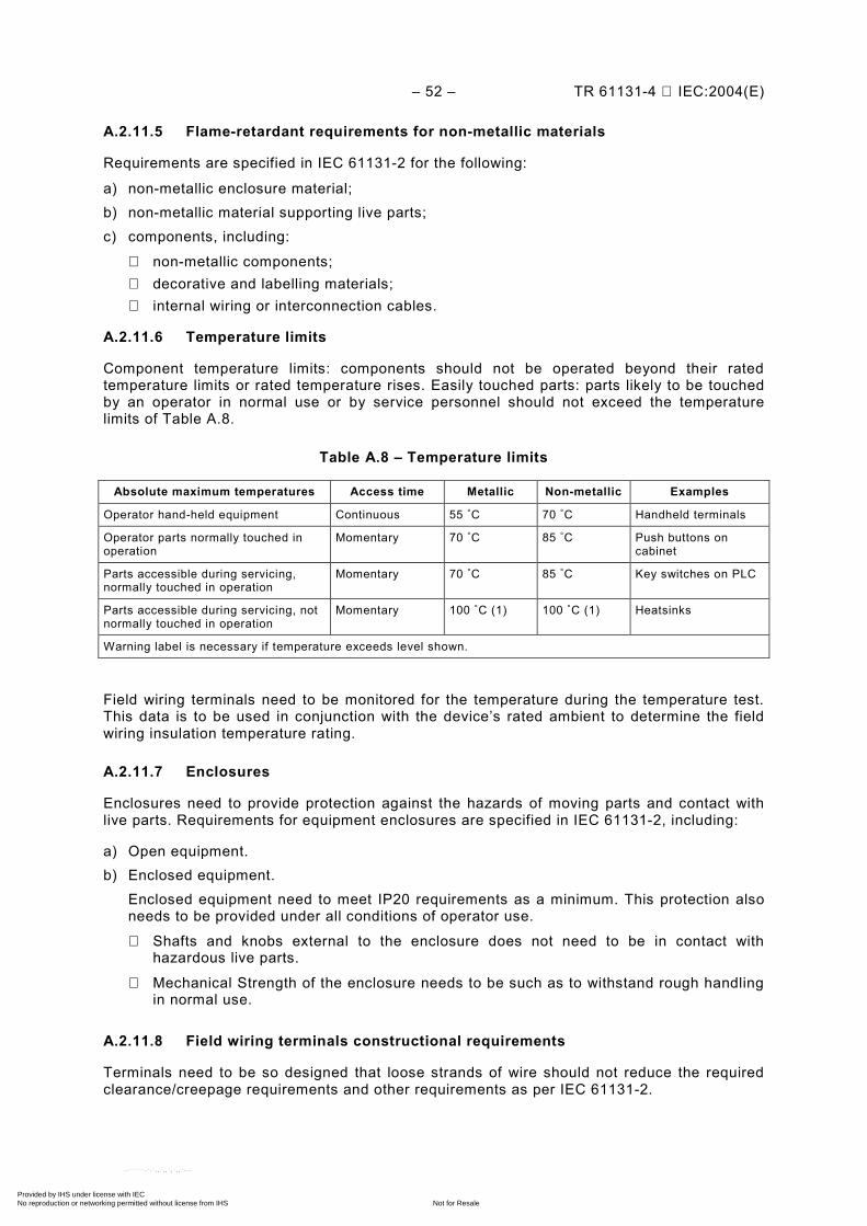
– 52 – TR 61131-4 IEC:2004(E)
A.2.11.5 Flame-retardant requirements for non-metallic materials
Requirements are specified in IEC 61131-2 for the following:
a) non-metallic enclosure material; b) non-metallic material supporting live parts; c) components, including:
non-metallic components; decorative and labelling materials; internal wiring or interconnection cables.
A.2.11.6 Temperature limits
Component temperature limits: components should not be operated beyond their rated temperature limits or rated temperature rises. Easily touched parts: parts likely to be touched by an operator in normal use or by service personnel should not exceed the temperature limits of Table A.8.
Table A.8 – Temperature limits
Absolute maximum temperatures Access time Metallic Non-metallic Examples
Operator hand-held equipment Continuous 55 °C 70 °C Handheld terminals
Operator parts normally touched in operation
Momentary 70 °C 85 °C Push buttons on cabinet
Parts accessible during servicing, normally touched in operation
Momentary 70 °C 85 °C Key switches on PLC
Parts accessible during servicing, not normally touched in operation
Momentary 100 °C (1) 100 °C (1) Heatsinks
Warning label is necessary if temperature exceeds level shown.
Field wiring terminals need to be monitored for the temperature during the temperature test. This data is to be used in conjunction with the device’s rated ambient to determine the field wiring insulation temperature rating.
A.2.11.7 Enclosures
Enclosures need to provide protection against the hazards of moving parts and contact with live parts. Requirements for equipment enclosures are specified in IEC 61131-2, including:
a) Open equipment. b) Enclosed equipment. Enclosed equipment need to meet IP20 requirements as a minimum. This protection also
needs to be provided under all conditions of operator use.
Shafts and knobs external to the enclosure does not need to be in contact with hazardous live parts.
Mechanical Strength of the enclosure needs to be such as to withstand rough handling in normal use.
A.2.11.8 Field wiring terminals constructional requirements
Terminals need to be so designed that loose strands of wire should not reduce the required clearance/creepage requirements and other requirements as per IEC 61131-2.
Copyright International Electrotechnical Commission Provided by IHS under license with IEC
Not for ResaleNo reproduction or networking permitted without license from IHS
--``````-`-`,,`,,`,`,,`---
TR 61131-4 IEC:2004(E) – 53 –
A.2.11.9 Provisions for protective earthing
The requirements specified below do not apply to SELV circuits where protective earthing is not required.
A.2.11.9.1 Protective earthing constructional requirements
The accessible parts of Class I equipment (e.g. chassis, framework and fixed metal parts of metal enclosures) other than those which do not constitute a danger need to be electrically interconnected and connected to a protective earth terminal for connection to an external protective conductor. This requirement can be met by structural parts providing adequate electrical continuity and applies whether the equipment is used on its own or incorporated in an assembly.
Cords or cables that supply power to portable peripherals need to be provided with a protective earthing conductor. Protective earthing conductor insulation, if provided, is to be green with a yellow stripe.
NOTE In North America, the colour green is also acceptable.
Accessible isolated conductive parts are considered not to constitute a danger if they are so located as to exclude any contact with live parts and withstand the dielectric test voltage specified in IEC 61131-2 for reinforced insulation corresponding to the highest rated operational voltage of the unit.
Class II equipment may have an internal functional bonding conductor but may not be provided with a protective earthing terminal or a protective earthing conductor in the mains power input cord.
A.2.11.10 Protective earthing terminal
If the PLC system is provided with a protective earthing terminal (class I equipment), the following requirements also apply in addition to the previous general connection specifications:
– The protective earthing terminal needs to be readily accessible and so placed that the connection of the equipment to the protective earthing conductor is maintained when the cover or any removable part is removed.
– Products which are intended for cord connected use (such as peripherals) need to be provided with a protective earthing terminal integral to the plug cap, or socket (if removable cord set).
– The protective earthing terminal needs to be of screw, stud or pressure type and needs to be made of a suitable corrosion resistant material.
– The clamping means of protective earthing terminals need to be adequately locked against accidental loosening and it should not be possible to loosen them without the aid of a tool.
– Protective earthing terminals and earthing contacts are not to be directly connected to the neutral terminal within the PLC system. This does not prevent the connection of appropriately rated devices (such as capacitors or surge suppression devices) between the protective earthing terminal and neutral.
– The protective earthing terminal and subsequent protective equipment internal to the PLC system need to comply with the test specified in IEC 61131-2.
The protective earthing terminal needs to have no other function.
Copyright International Electrotechnical Commission Provided by IHS under license with IEC
Not for ResaleNo reproduction or networking permitted without license from IHS
--``````-`-`,,`,,`,`,,`---
– 54 – TR 61131-4 IEC:2004(E)
A.2.11.11 Wiring
IEC 61131-2 specifies wiring requirements applicable to all wiring provided by the manufacturer for the internal and/or external wiring of the PLC system, including internal wiring and interconnecting wiring. This Subclause does not apply to SELV/PELV circuits, earthing or bonding conductors.
A.2.11.11.1 Internal wiring
Insulation on all internal wiring is to be rated for the voltage and temperature of use.
A.2.11.11.2 Interconnection wiring
Cables and cords provided for interconnection of equipment should comply with requirements as for internal wiring.
A.2.11.11.3 Mains power input cord
The mains power input cord provided by the manufacturer should comply with the mains power input cord requirements in IEC 61010-1.
The circuitry connected to a cord set (removable or fixed) needs to be so designed that there is no risk of electric shock after 1 s when touching the pins of the plug and/or receptacle. Test are to be conducted in accordance with specifications of IEC 61131-2.
A.2.11.12 Switching devices
Switching devices should be used within their ratings, as per IEC 60947-5-1, or equipment utilizing them need to be subjected to the overload and endurance tests specified in IEC 61131-2. The endurance test is not conducted on solid state output devices for general or resistive use.
A.2.11.13 Components
Components should comply with the applicable safety requirements of the relevant IEC product standard(s) or have been approved by a recognized testing authority for conformity with applicable safety requirements and need not be re-tested.
NOTE Components are parts of PLC system units; e.g., capacitors, resistors, printed circuit boards, relays, transformers, switches.
A.2.11.14 Battery requirements
Battery cases or compartments need to be designed to protect against accumulation of flammable gases or damage from spilling of corrosive liquid as applicable.
Rechargeable and non-rechargeable batteries, if used in the PLC, need to be provided with suitable protection, internal or external to the battery cell, so as to minimize the risk of battery explosion. Parameters to be considered in the design should include temperature, possibility/prevention of reverse current flow, limited discharge, etc.
Means need to be provided to prevent charging and to limit the discharge current of non-rechargeable batteries in both normal and single fault conditions.
A.2.11.15 Maximum voltage and minimum voltage
The equipment should operate as intended without an increased risk of fire or electric shock when subjected to maximum voltage or minimum voltage conditions. This requirement needs to be verified as per IEC 61131-2.
Copyright International Electrotechnical Commission Provided by IHS under license with IEC
Not for ResaleNo reproduction or networking permitted without license from IHS
--``````-`-`,,`,,`,`,,`---

TR 61131-4 IEC:2004(E) – 55 –
A.2.11.16 Markings and identification
Markings as indicated below need to be visible from the exterior of enclosed equipment, or be visible after removing a cover or opening a door without the aid of a tool, if the cover or door is intended to be removed or opened by an operator. For open equipment, markings are permitted to be on any surface that becomes visible after removal of the equipment from the rack or panel.
For all equipment, as a minimum, the information marked on the device need to identify the manufacturer (the company bringing the product to market) and the device. The remaining information needs to be provided in the data sheet, supplied with the device.
The following information needs to be provided by the manufacturer:
– manufacturer’s name, trademark or other identification; – model/catalogue number, type designation or name; – hardware serial number or series and/or revision level, and date code or equivalent; – information on replaceable fuses, including current, voltage and type; – live parts and protective earth terminals markings as required.
A.2.11.16.1 External wiring terminals identification
External wiring terminals need to be marked to indicate the proper connections for the power supply, load, control circuit, and the like, or a wiring diagram coded to the terminal marking needs to be provided. A marking or manufacturers installation instructions need to be provided to identify the temperature rating of field wiring to be connected to the wiring terminals.
A.2.11.16.2 Live parts
A live part exceeding SELV limits and likely to be mistaken as dead-metal (non-energized metal) and exposed to service personnel needs to be marked with the following “Dangerous voltage” symbol:
NOTE Symbol according to IEC 60417- 5036 (DB:2002-10).
A.2.11.16.3 Protective earth terminals markings
The protective earth terminal markings need to be durable and clearly identifiable. The identification needs to be achieved by the notation PE, or by a graphical symbol for use on equipment or by the colour green-yellow.
NOTE Notation PE according to 5.3 of IEC 60445. In North America, the colour green only is also acceptable.
The graphical symbol for protective earth is:
NOTE Symbol according to IEC 60417- 5019-a (DB:2002-10).
Copyright International Electrotechnical Commission Provided by IHS under license with IEC
Not for ResaleNo reproduction or networking permitted without license from IHS
--``````-`-`,,`,,`,`,,`---
– 56 – TR 61131-4 IEC:2004(E)
A.2.11.16.4 Equipment protected by double/reinforced insulation
Equipment protected throughout by double/reinforced insulation (Class II) needs to be marked with the following symbol unless it is provided with a protective terminal.
Equipment, which is only partially protected by double/reinforced insulation, should not bear this symbol.
NOTE Symbol according to IEC 60417- 5172 (DB:2002-10).
A.2.11.16.5 Equipment supplied by SELV/PELV
Equipment intended to only be energized by a SELV or PELV source of supply needs to be so marked on equipment and/or provided in product literature.
A.2.11.16.6 Rating information
Equipment needs to be marked with the following as applicable:
– rated voltage(s) or range of voltage in volts (V); – rated frequency in Hertz (Hz); – kind of supply system (AC, DC, AC/DC or the symbols 5032 (DB:2002-10), 5931
(DB:2002-10) or 5033 (DB:2002-10) from IEC 60417); – number of phase conductors if more than one; – rated current in Amperes (A); and/or – rated input and/or output power in Watts (W) or Volt-Amperes (VA).
For open type equipment, the information needs to be marked on the equipment or in the manual. This includes: requirements for safety type tests and verifications test and verifications for safety in accordance with IEC 61131-2, and requirements for safety routine tests and verifications safety routine tests or an equivalent verification method.
A.2.11.17 Requirement for dielectric strength verification
Protection against electric shock needs to be verified between non-SELV circuits and SELV circuits, non-SELV circuits and accessible conductive parts, and isolated non-SELV circuits. This verification needs to be performed by one of the following approaches:
– routine dielectric withstand testing of the product in accordance with IEC 61131-2; – verification, during product development, that all of the relevant insulating materials and
creepage and clearance distances of the product and that all isolating components meet one of the following:
– the component requirements of IEC 61131-2; – 100 % dielectric withstand tested; – verified by measurement to meet the required creepage and clearance distances.
A.2.11.18 Requirement for protective earthing verification
The manufacturer needs to verify protective earthing continuity between the protective earthing interface/port and all operator accessible metal parts intended to be earthed, in accordance with the test described in IEC 61131-2.
Copyright International Electrotechnical Commission Provided by IHS under license with IEC
Not for ResaleNo reproduction or networking permitted without license from IHS
--``````-`-`,,`,,`,`,,`---
TR 61131-4 IEC:2004(E) – 57 –
A.2.11.19 Requirements for information on safety
Information on safety needs to be provided by the manufacturer in accordance with IEC 61131-2.
A.2.11.20 Safety type tests and verifications
The safety related tests and verifications prescribed in IEC 61131-2 are mainly for the manufacturer. These include the following:
A.2.11.21 Safety related mechanical tests and verifications – impact withstand test; – operator accessibility test; – general examination of openings; – wire flexibility test; – temperature test; – protective coating test; – rigidity test; – clearance and creepage verification; – field-wiring terminals constructional verification.
A.2.11.22 Safety related electrical tests – dielectric withstand verification test; – protective earthing continuity test; – stored energy injury risk test; – overload test; – endurance test.
A.2.11.23 Single-fault condition test – breakdown of component test; – protective impedance test; – mains transformer test.
A.2.12 Safety routine tests
These tests include:
– dielectric withstand test; – dielectric withstand verification test (routine dielectric withstand test); – protective earthing test.
A.2.13 Safety information to be provided by the manufacturer
The manufacturer's data are to include the following information as a minimum:
– Protective earthing requirements and recommendations concerning personnel safety circuits.
– Requirements for the maintenance of protective devices, such as protective earthing circuits, overcurrent protective devices, and batteries utilized for memory back-up, etc.
Copyright International Electrotechnical Commission Provided by IHS under license with IEC
Not for ResaleNo reproduction or networking permitted without license from IHS
--``````-`-`,,`,,`,`,,`---
– 58 – TR 61131-4 IEC:2004(E)
– If the PLC system is provided as "open equipment", a suitable enclosure is required to provide the necessary level of safety and environmental protection and guidelines for mounting, spacing, and/or internal barriers or shields if needed for safety.
– Precautionary instructions, if removal of any module while the equipment is in operation can affect safety related to electrical shock, fire hazard and electrical damage.
– A statement of the intended use of the PLC system relative to Overvoltage Category. – Isolation potentials between channel and other circuits (including ground) and between
channels under normal conditions. – Information to be made available can be in other than printed form.
In addition, the following information is to be provided:
A.2.13.1 Information on evaluation of enclosures for open equipment (power dissipation)
The manufacturer's documents are to provide information to allow the evaluation of the power dissipation of every PLC configuration, sub-assembly and module and provide information regarding minimum spacing required to assure adequate cooling under normal service conditions.
A.2.13.2 Information on mechanical terminal connection
The manufacturer is to provide the following information through convenient documentation and/or marking:
a) Type, cross-sectional area and material of the conductors that may be connected to the PLC system.
b) Recommendations for use of shielded cables, and how they are to be connected and earthed.
A.2.14 Illustration of PLC system hardware definition
Figure A.7 illustrates the hardware in the PLC system as defined for the purposes of IEC 61131-1 and IEC 61131-2.
Copyright International Electrotechnical Commission Provided by IHS under license with IEC
Not for ResaleNo reproduction or networking permitted without license from IHS
--``````-`-`,,`,,`,`,,`---
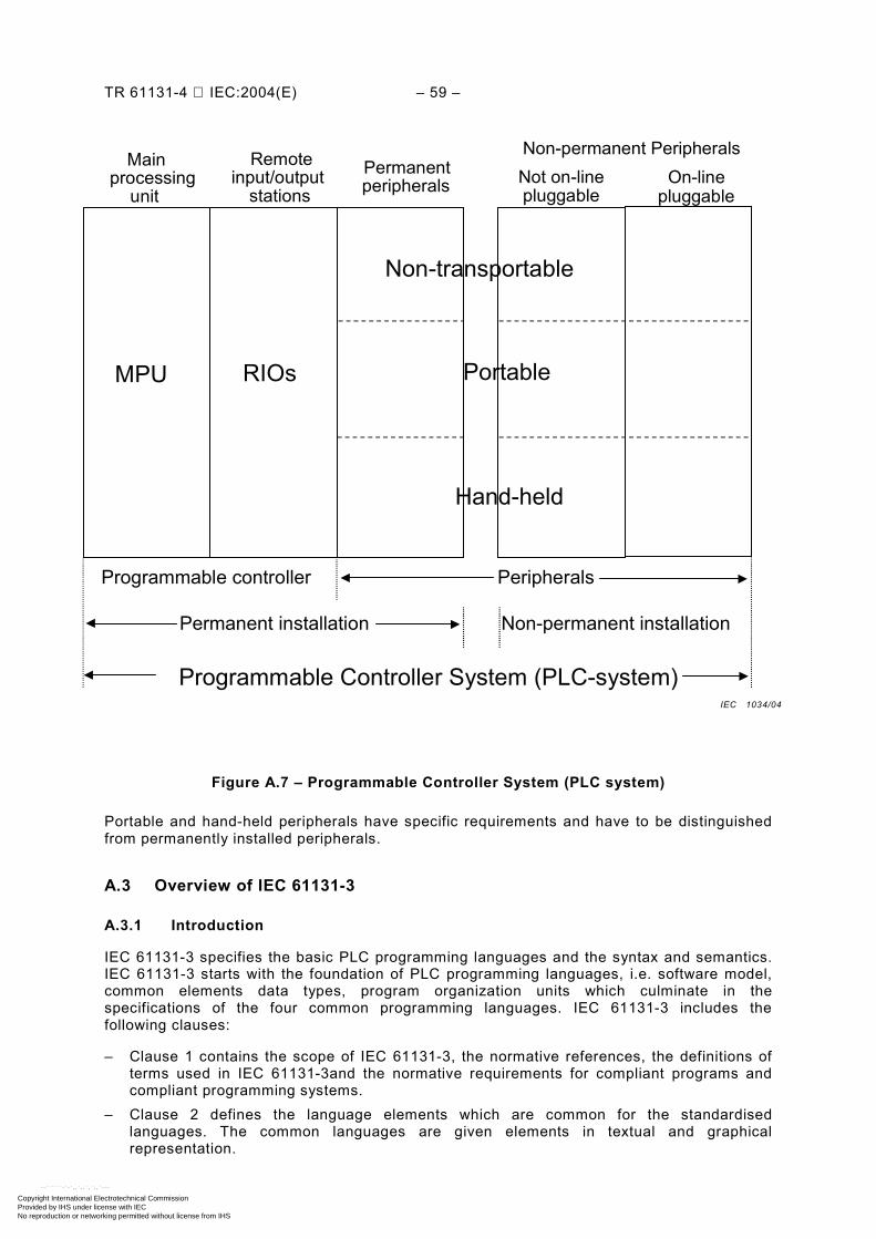
TR 61131-4 IEC:2004(E) – 59 –
Main
processing unit
Remote input/output
stations Permanentperipherals
Non-permanent PeripheralsNot on-line pluggable
On-line pluggable
MPU RIOs
Non-transportable
Portable
Hand-held
Programmable controller Peripherals
Permanent installation Non-permanent installation
Programmable Controller System (PLC-system)
Figure A.7 – Programmable Controller System (PLC system)
Portable and hand-held peripherals have specific requirements and have to be distinguished from permanently installed peripherals.
A.3 Overview of IEC 61131-3
A.3.1 Introduction
IEC 61131-3 specifies the basic PLC programming languages and the syntax and semantics. IEC 61131-3 starts with the foundation of PLC programming languages, i.e. software model, common elements data types, program organization units which culminate in the specifications of the four common programming languages. IEC 61131-3 includes the following clauses:
– Clause 1 contains the scope of IEC 61131-3, the normative references, the definitions of terms used in IEC 61131-3and the normative requirements for compliant programs and compliant programming systems.
– Clause 2 defines the language elements which are common for the standardised languages. The common languages are given elements in textual and graphical representation.
IEC 1034/04
Copyright International Electrotechnical Commission Provided by IHS under license with IEC
Not for ResaleNo reproduction or networking permitted without license from IHS
--``````-`-`,,`,,`,`,,`---
– 60 – TR 61131-4 IEC:2004(E)
– Clause 3 and 4 defines the various standard languages. Two textual languages "Instruction List" and "Structured Text" and two graphical languages "Ladder Diagram" and "Function Block Diagram" are normative.
Sequential Function Chart (SFC) elements are defined for structuring the internal organization of programmable controller programs and function blocks. Also, configuration elements are defined which support the installation of programmable controller programs into programmable controller systems.
In the annexes of IEC 61131-3, the formal specifications, keywords, examples, etc. are given.
A.3.2 General
A.3.2.1 Scope
IEC 61131-3 specifies syntax and semantics of programming languages for programmable controllers as defined in IEC 61131-1.
A.3.2.2 Definitions
Some of the definitions listed in IEC 61131-3 are examples for use of PLC language terms in IEC 61131-3:
a) action Boolean variable, or a collection of operations to be performed, together with an
associated control structure. b) action block Graphical language element which utilizes a Boolean input variable to determine the value
of a Boolean output variable or the enabling condition for an action, according to a predetermined control structure.
c) access path The association of a symbolic name with a variable for the purpose of open
communication. d) bistable function block
Function block with two stable states controlled by one or more inputs. e) call
Language construct for invoking the execution of a function or function block. f) configuration Language element corresponding to a programmable controller system as defined in
IEC 61131-1. g) declaration The mechanism for establishing the definition of a language element. A declaration
normally involves attaching an identifier to the language element, and allocating attributes such as data types and algorithms to it.
h) function (procedure) Program organization unit which, when executed, yields exactly one data element and
possibly additional output variables (which may be multi-valued, for example, an array or structure), and whose invocation can be used in textual languages as an operand in an expression.
Copyright International Electrotechnical Commission Provided by IHS under license with IEC
Not for ResaleNo reproduction or networking permitted without license from IHS
--``````-`-`,,`,,`,`,,`---
TR 61131-4 IEC:2004(E) – 61 –
i) function block (function block type) PLC programming language element consisting of: – the structure of data structure partitioned into input, output, and internal variables; and – a set of operations to be performed upon the elements of the data structure when an
instance of the function block type is invoked. j) function block diagram Network in which the nodes are function block instances, graphically represented
functions (procedures), variables, literals, and labels. k) global variable
Variable whose scope is global. l) in-out variable
Variable that is declared in a VAR_IN_OUT...END_VAR block.
m) instance Individual, named copy of the data structure associated with a function block type or
program type, which persists from one invocation of the associated operations to the next. n) instantiation
The creation of an instance. o) invocation The process of initiating the execution of the operations specified in a program
organization unit. p) keyword
Lexical unit that characterises a language element, for example “IF”. q) label Language construction naming an instruction, network or group of networks, including an
identifier. r) network
Arrangement of nodes and interconnecting branches. s) pragma
Language construct for the inclusion of text in a program organization unit which may affect the preparation of the program for execution.
t) resource Language element corresponding to a “signal processing function” and its “man-machine
interface” and “sensor and actuator interface functions”, if any, as defined in IEC 61131-1. u) semantics The relationships between the symbolic elements of a programming language and their
meanings, interpretation and use. v) step
Situation in which the behaviour of a program organization unit with respect to its inputs and outputs follows a set of rules defined by the associated actions of the step.
w) task
Execution control element providing for periodic or triggered execution of a group of associated program organization units.
x) transition
The condition whereby control passes from one or more predecessor steps to one or more successor steps along a directed link.
Copyright International Electrotechnical Commission Provided by IHS under license with IEC
Not for ResaleNo reproduction or networking permitted without license from IHS
--``````-`-`,,`,,`,`,,`---
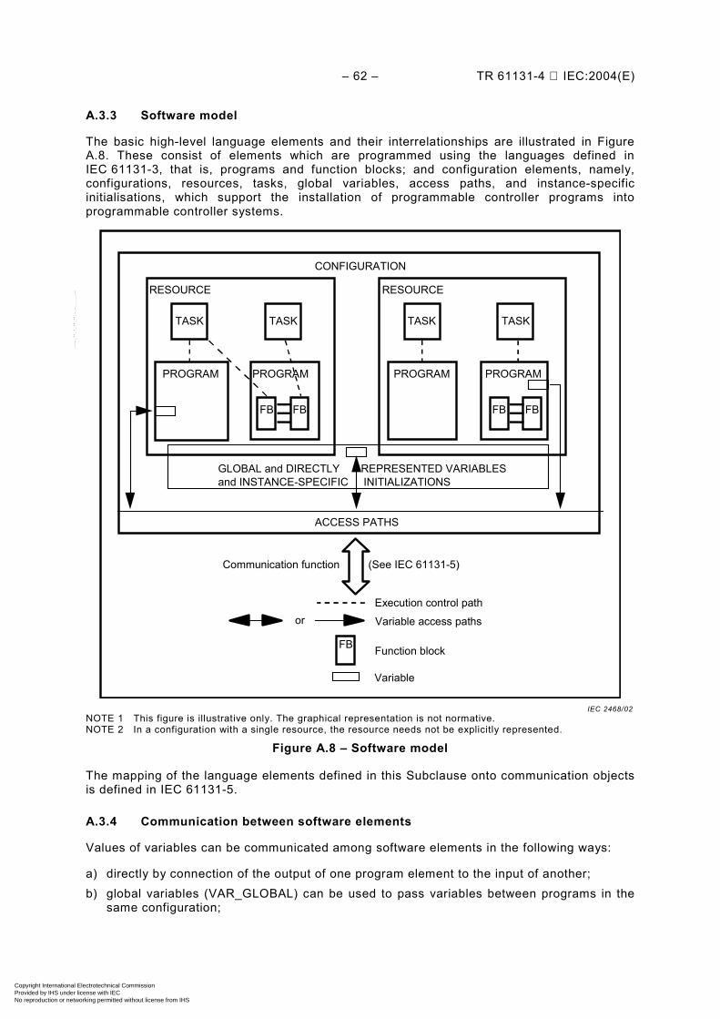
– 62 – TR 61131-4 IEC:2004(E)
A.3.3 Software model
The basic high-level language elements and their interrelationships are illustrated in Figure A.8. These consist of elements which are programmed using the languages defined in IEC 61131-3, that is, programs and function blocks; and configuration elements, namely, configurations, resources, tasks, global variables, access paths, and instance-specific initialisations, which support the installation of programmable controller programs into programmable controller systems.
CONFIGURATION
RESOURCE
TASK TASK
PROGRAM PROGRAM
FB FB
RESOURCE
TASK TASK
PROGRAM PROGRAM
FB FB
GLOBAL and DIRECTLY REPRESENTED VARIABLESand INSTANCE-SPECIFIC INITIALIZATIONS
ACCESS PATHS
Execution control path
Variable access paths
FB Function block
Variable
or
Communication function (See IEC 61131-5)
NOTE 1 This figure is illustrative only. The graphical representation is not normative. NOTE 2 In a configuration with a single resource, the resource needs not be explicitly represented.
Figure A.8 – Software model
The mapping of the language elements defined in this Subclause onto communication objects is defined in IEC 61131-5.
A.3.4 Communication between software elements
Values of variables can be communicated among software elements in the following ways:
a) directly by connection of the output of one program element to the input of another; b) global variables (VAR_GLOBAL) can be used to pass variables between programs in the
same configuration;
IEC 2468/02
Copyright International Electrotechnical Commission Provided by IHS under license with IEC
Not for ResaleNo reproduction or networking permitted without license from IHS
--``````-`-`,,`,,`,`,,`---

TR 61131-4 IEC:2004(E) – 63 –
c) using the communication function blocks defined in IEC 61131-5 between different parts of a program, between programs in the same or different configurations, or between a programmable controller program and a non-programmable controller system;
d) data can be made available by access paths (VAR_ACCESS) between programmable controllers or non-programmable controller systems.
A.3.5 Programming model
The elements of programmable controller programming languages are classified as follows:
Data types Variables Program organization units
Functions Function blocks Programs
Sequential Function Chart (SFC) elements Configuration elements
Global variables Resources Access paths Tasks
Figure A.9 shows the combination of PLC program language elements.
Copyright International Electrotechnical Commission Provided by IHS under license with IEC
Not for ResaleNo reproduction or networking permitted without license from IHS
--``````-`-`,,`,,`,`,,`---
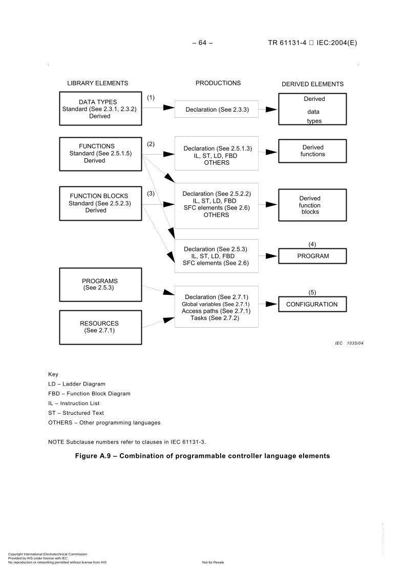
– 64 – TR 61131-4 IEC:2004(E)
LIBRARY ELEMENTS PRODUCTIONS DERIVED ELEMENTS
DATA TYPES Standard (See 2.3.1, 2.3.2)
Derived
FUNCTIONS Standard (See 2.5.1.5)
Derived
FUNCTION BLOCKS Standard (See 2.5.2.3)
Derived
PROGRAMS
RESOURCES
Declaration (See 2.5.1.3) IL, ST, LD, FBD
OTHERS
Declaration (See 2.5.2.2) IL, ST, LD, FBD
SFC elements (See 2.6) OTHERS
Declaration (See 2.5.3)IL, ST, LD, FBD
SFC elements (See 2.6)
Tasks (See 2.7.2)
Declaration (See 2.7.1)Global variables (See 2.7.1) Access paths (See 2.7.1)
Derived
data types
Derived functions
Derived function blocks
PROGRAM
CONFIGURATION
Declaration (See 2.3.3)
(1)
(2)
(3)
(4)
(5) (See 2.5.3)
(See 2.7.1)
Key
LD – Ladder Diagram
FBD – Function Block Diagram
IL – Instruction List
ST – Structured Text
OTHERS – Other programming languages
NOTE Subclause numbers refer to clauses in IEC 61131-3.
Figure A.9 – Combination of programmable controller language elements
IEC 1035/04
Copyright International Electrotechnical Commission Provided by IHS under license with IEC
Not for ResaleNo reproduction or networking permitted without license from IHS
--``````-`-`,,`,,`,`,,`---
TR 61131-4 IEC:2004(E) – 65 –
A.3.6 Compliance
This Subclause defines the requirements for programmable controller systems and programs which claim compliance with IEC 61131-3.
A.3.6.1 System compliance
A PLC system which claims to comply, wholly or partially, with the requirements of IEC 61131-3 shall do so only as described in the following manner.
A compliance statement shall be included in the documentation accompanying the system, or is produced by the system itself. The form of the compliance statement is:
“This system complies with the requirements of IEC 61131-3, for the following language features: ” followed by a set of compliance tables.
For details on the compliance tables and the remaining compliance requirements, see IEC 61131-3.
A.3.6.2 Program compliance
A programmable controller program complying with the requirements of IEC 61131-3 needs to:
a) use only those features specified in this standard for the particular language used; b) not use any features identified as extensions to the language; c) not rely on any particular interpretation of implementation-dependent features.
The results produced by a complying program is to be the same when processed by any complying system which supports the features used by the program, such results are influenced by program execution timing, the use of implementation-dependent features in the program, and the execution of error handling procedures.
A.3.7 Common language elements
The following language elements are common to all standardized programmable controller languages to assure their harmonized usage and exchange.
A.3.7.1 Printed characters
Printed characters include:
– character set; – identifiers; – keywords; – white space; – comments; – pragmas.
A.3.7.2 External representation of data – numerical literals; – character string literals; – time literals:
- duration; - time of day.
Copyright International Electrotechnical Commission Provided by IHS under license with IEC
Not for ResaleNo reproduction or networking permitted without license from IHS
--``````-`-`,,`,,`,`,,`---
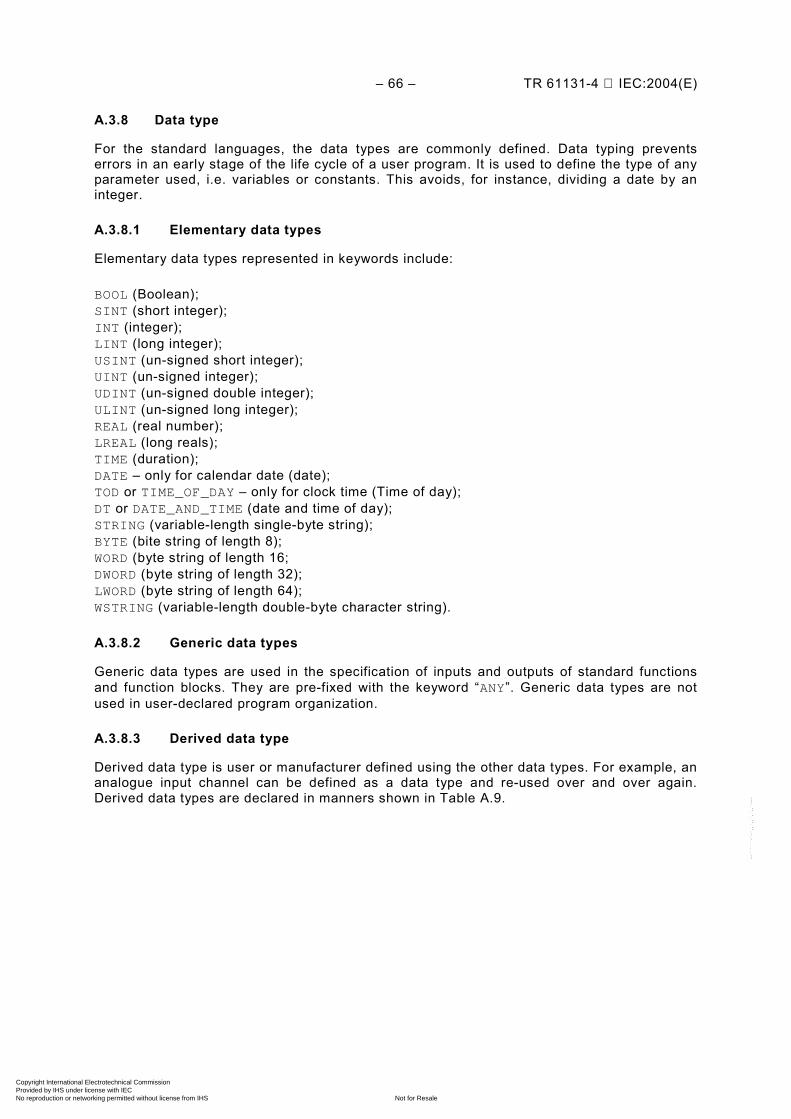
– 66 – TR 61131-4 IEC:2004(E)
A.3.8 Data type
For the standard languages, the data types are commonly defined. Data typing prevents errors in an early stage of the life cycle of a user program. It is used to define the type of any parameter used, i.e. variables or constants. This avoids, for instance, dividing a date by an integer.
A.3.8.1 Elementary data types
Elementary data types represented in keywords include:
BOOL (Boolean); SINT (short integer); INT (integer); LINT (long integer); USINT (un-signed short integer); UINT (un-signed integer); UDINT (un-signed double integer); ULINT (un-signed long integer); REAL (real number); LREAL (long reals); TIME (duration); DATE – only for calendar date (date); TOD or TIME_OF_DAY – only for clock time (Time of day); DT or DATE_AND_TIME (date and time of day); STRING (variable-length single-byte string); BYTE (bite string of length 8); WORD (byte string of length 16; DWORD (byte string of length 32); LWORD (byte string of length 64); WSTRING (variable-length double-byte character string).
A.3.8.2 Generic data types
Generic data types are used in the specification of inputs and outputs of standard functions and function blocks. They are pre-fixed with the keyword “ANY”. Generic data types are not used in user-declared program organization.
A.3.8.3 Derived data type
Derived data type is user or manufacturer defined using the other data types. For example, an analogue input channel can be defined as a data type and re-used over and over again. Derived data types are declared in manners shown in Table A.9.
Copyright International Electrotechnical Commission Provided by IHS under license with IEC
Not for ResaleNo reproduction or networking permitted without license from IHS
--``````-`-`,,`,,`,`,,`---
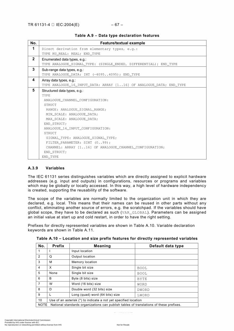
TR 61131-4 IEC:2004(E) – 67 –
Table A.9 – Data type declaration features
No. Feature/textual example 1 Direct derivation from elementary types, e.g.:
TYPE RU_REAL: REAL; END_TYPE
2 Enumerated data types, e.g.: TYPE ANALOGUE_SIGNAL_TYPE: (SINGLE_ENDED, DIFFERENTIAL); END_TYPE
3 Sub-range data types, e.g.: TYPE ANALOGUE_DATA: INT (-4095..4095); END_TYPE
4 Array data types, e.g.: TYPE ANALOGUE_16_INPUT_DATA: ARRAY [1..16] OF ANALOGUE_DATA; END_TYPE
5 Structured data types, e.g.: TYPE
ANALOGUE_CHANNEL_CONFIGURATION:
STRUCT
RANGE: ANALOGUE_SIGNAL_RANGE;
MIN_SCALE: ANALOGUE_DATA;
MAX_SCALE: ANALOGUE_DATA;
END_STRUCT;
ANALOGUE_16_INPUT_CONFIGURATION:
STRUCT
SIGNAL_TYPE: ANALOGUE_SIGNAL_TYPE;
FILTER_PARAMETER: SINT (0..99);
CHANNEL: ARRAY [1..16] OF ANALOGUE_CHANNEL_CONFIGURATION;
END_STRUCT;
END_TYPE
A.3.9 Variables
The IEC 61131 series distinguishes variables which are directly assigned to explicit hardware addresses (e.g. input and outputs) in configurations, resources or programs and variables which may be globally or locally accessed. In this way, a high level of hardware independency is created, supporting the reusability of the software.
The scope of the variables are normally limited to the organization unit in which they are declared, e.g. local. This means that their names can be reused in other parts without any conflict, eliminating another source of errors, e.g. the scratchpad. If the variables should have global scope, they have to be declared as such (VAR_GLOBAL). Parameters can be assigned an initial value at start up and cold restart, in order to have the right setting.
Prefixes for directly represented variables are shown in Table A.10. Variable declaration keywords are shown in Table A.11.
Table A.10 – Location and size prefix features for directly represented variables
No. Prefix Meaning Default data type 1 I Input location 2 Q Output location 3 M Memory location 4 X Single bit size BOOL 5 None Single bit size BOOL 6 B Byte (8 bits) size BYTE 7 W Word (16 bits) size WORD 8 D Double word (32 bits) size DWORD 9 L Long (quad) word (64 bits) size LWORD 10 Use of an asterisk (*) to indicate a not yet specified location NOTE National standards organizations can publish tables of translations of these prefixes.
Copyright International Electrotechnical Commission Provided by IHS under license with IEC
Not for ResaleNo reproduction or networking permitted without license from IHS
--``````-`-`,,`,,`,`,,`---
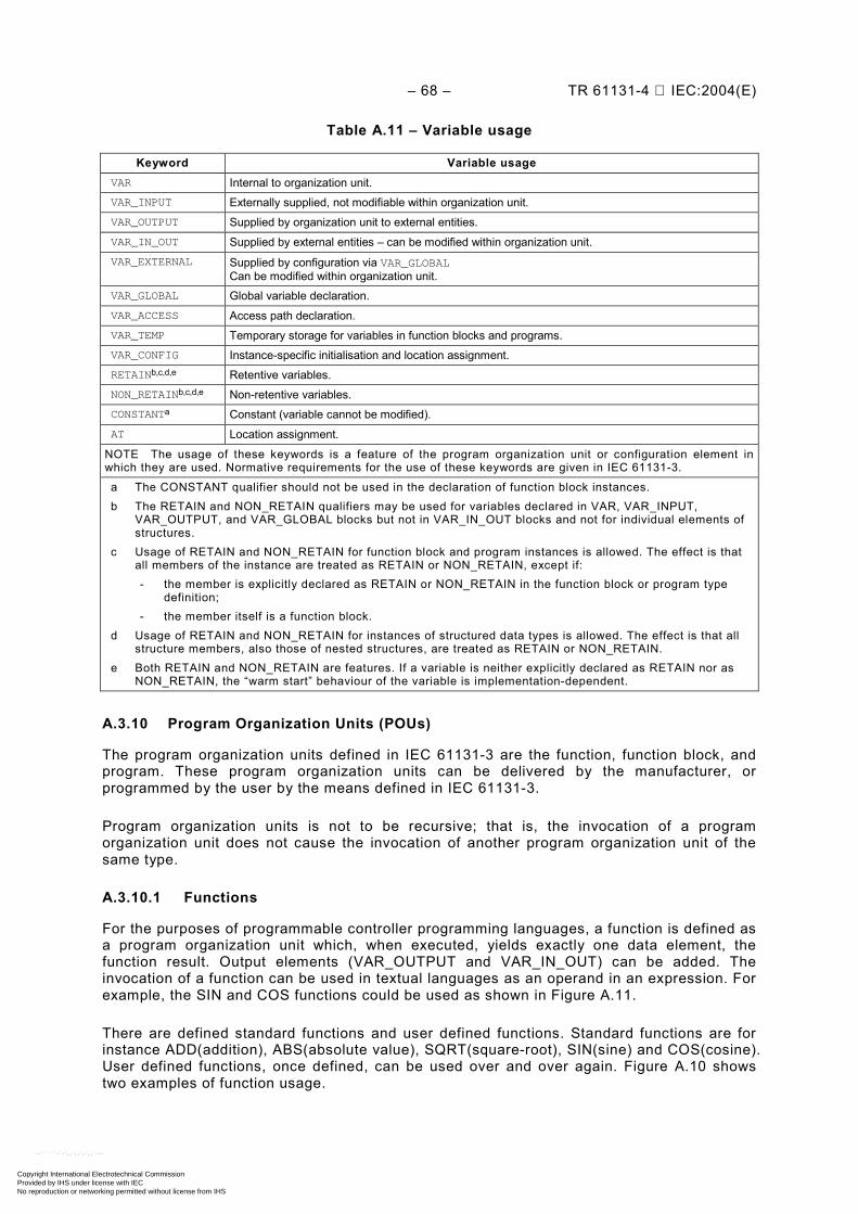
– 68 – TR 61131-4 IEC:2004(E)
Table A.11 – Variable usage
Keyword Variable usage VAR Internal to organization unit. VAR_INPUT Externally supplied, not modifiable within organization unit. VAR_OUTPUT Supplied by organization unit to external entities. VAR_IN_OUT Supplied by external entities – can be modified within organization unit. VAR_EXTERNAL Supplied by configuration via VAR_GLOBAL
Can be modified within organization unit. VAR_GLOBAL Global variable declaration. VAR_ACCESS Access path declaration. VAR_TEMP Temporary storage for variables in function blocks and programs. VAR_CONFIG Instance-specific initialisation and location assignment. RETAINb,c,d,e Retentive variables. NON_RETAINb,c,d,e Non-retentive variables. CONSTANTa Constant (variable cannot be modified). AT Location assignment.
NOTE The usage of these keywords is a feature of the program organization unit or configuration element in which they are used. Normative requirements for the use of these keywords are given in IEC 61131-3.
a The CONSTANT qualifier should not be used in the declaration of function block instances. b The RETAIN and NON_RETAIN qualifiers may be used for variables declared in VAR, VAR_INPUT,
VAR_OUTPUT, and VAR_GLOBAL blocks but not in VAR_IN_OUT blocks and not for individual elements of structures.
c Usage of RETAIN and NON_RETAIN for function block and program instances is allowed. The effect is that all members of the instance are treated as RETAIN or NON_RETAIN, except if: - the member is explicitly declared as RETAIN or NON_RETAIN in the function block or program type
definition; - the member itself is a function block.
d Usage of RETAIN and NON_RETAIN for instances of structured data types is allowed. The effect is that all structure members, also those of nested structures, are treated as RETAIN or NON_RETAIN.
e Both RETAIN and NON_RETAIN are features. If a variable is neither explicitly declared as RETAIN nor as NON_RETAIN, the “warm start” behaviour of the variable is implementation-dependent.
A.3.10 Program Organization Units (POUs)
The program organization units defined in IEC 61131-3 are the function, function block, and program. These program organization units can be delivered by the manufacturer, or programmed by the user by the means defined in IEC 61131-3.
Program organization units is not to be recursive; that is, the invocation of a program organization unit does not cause the invocation of another program organization unit of the same type.
A.3.10.1 Functions
For the purposes of programmable controller programming languages, a function is defined as a program organization unit which, when executed, yields exactly one data element, the function result. Output elements (VAR_OUTPUT and VAR_IN_OUT) can be added. The invocation of a function can be used in textual languages as an operand in an expression. For example, the SIN and COS functions could be used as shown in Figure A.11.
There are defined standard functions and user defined functions. Standard functions are for instance ADD(addition), ABS(absolute value), SQRT(square-root), SIN(sine) and COS(cosine). User defined functions, once defined, can be used over and over again. Figure A.10 shows two examples of function usage.
Copyright International Electrotechnical Commission Provided by IHS under license with IEC
Not for ResaleNo reproduction or networking permitted without license from IHS
--``````-`-`,,`,,`,`,,`---
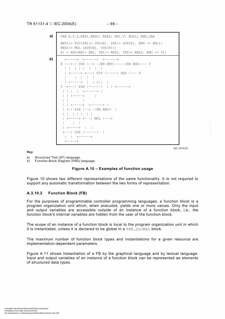
TR 61131-4 IEC:2004(E) – 69 –
a) VAR X,Y,Z,RES1,RES2: REAL; EN1,V: BOOL; END_VAR
RES1:= DIV(IN1:= COS(X), IN2:= SIN(Y), ENO => EN1);
RES2:= MUL (SIN(X), COS(Y));
Z: = ADD(EN:= EN1, IN1:= RES1, IN2:= RES2, ENO => V);
b) +-----+ +------+ +------+
X ---+-| COS |--+ -|EN ENO|-----|EN ENO|--- V
| | | | | | | |
| +-----+ +---| DIV |-----| ADD |--- Z
| | | | |
| +-----+ | | +-| |
Y -+---| SIN |------| | | +------+
| | | | +------+ |
| | +-----+ |
| | |
| | +-----+ +------+ |
| +-| SIN |--+ -|EN ENO|- |
| | | | | | |
| +-----+ +- -| MUL |---+
| | |
| +-----+ | |
+---| COS |------| |
| | +------+
+-----+
Key
a) Structured Text (ST) language. b) Function Block Diagram (FBD) language.
Figure A.10 – Examples of function usage
Figure 10 shows two different representations of the same functionality. It is not required to support any automatic transformation between the two forms of representation.
A.3.10.2 Function Block (FB)
For the purposes of programmable controller programming languages, a function block is a program organization unit which, when executed, yields one or more values. Only the input and output variables are accessible outside of an instance of a function block, i.e., the function block's internal variables are hidden from the user of the function block.
The scope of an instance of a function block is local to the program organization unit in which it is instantiated, unless it is declared to be global in a VAR_GLOBAL block.
The maximum number of function block types and instantiations for a given resource are implementation-dependent parameters.
Figure A.11 shows instantiation of a FB by the graphical language and by textual language. Input and output variables of an instance of a function block can be represented as elements of structured data types.
IEC 2474/02
Copyright International Electrotechnical Commission Provided by IHS under license with IEC
Not for ResaleNo reproduction or networking permitted without license from IHS
--``````-`-`,,`,,`,`,,`---
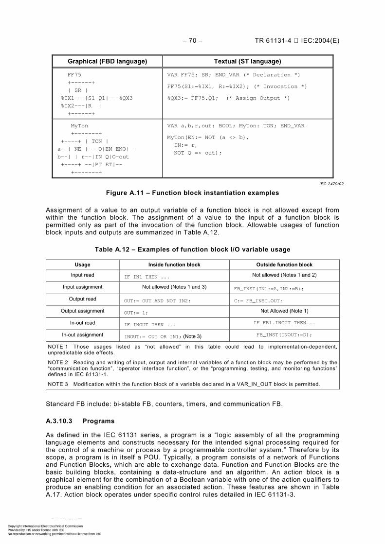
– 70 – TR 61131-4 IEC:2004(E)
Graphical (FBD language) Textual (ST language)
FF75
+------+
| SR |
%IX1---|S1 Q1|---%QX3
%IX2---|R |
+------+
VAR FF75: SR; END_VAR (* Declaration *)
FF75(S1:=%IX1, R:=%IX2); (* Invocation *)
%QX3:= FF75.Q1; (* Assign Output *)
MyTon
+-------+
+----+ | TON |
a--| NE |---O|EN ENO|--
b--| | r--|IN Q|O-out
+----+ --|PT ET|--
+-------+
VAR a,b,r,out: BOOL; MyTon: TON; END_VAR
MyTon(EN:= NOT (a <> b),
IN:= r,
NOT Q => out);
Figure A.11 – Function block instantiation examples
Assignment of a value to an output variable of a function block is not allowed except from within the function block. The assignment of a value to the input of a function block is permitted only as part of the invocation of the function block. Allowable usages of function block inputs and outputs are summarized in Table A.12.
Table A.12 – Examples of function block I/O variable usage
Usage Inside function block Outside function block
Input read IF IN1 THEN ... Not allowed (Notes 1 and 2)
Input assignment Not allowed (Notes 1 and 3) FB_INST(IN1:=A,IN2:=B);
Output read OUT:= OUT AND NOT IN2; C:= FB_INST.OUT;
Output assignment OUT:= 1; Not Allowed (Note 1)
In-out read IF INOUT THEN ... IF FB1.INOUT THEN...
In-out assignment INOUT:= OUT OR IN1; (Note 3) FB_INST(INOUT:=D);
NOTE 1 Those usages listed as “not allowed” in this table could lead to implementation-dependent, unpredictable side effects.
NOTE 2 Reading and writing of input, output and internal variables of a function block may be performed by the “communication function”, “operator interface function”, or the “programming, testing, and monitoring functions” defined in IEC 61131-1.
NOTE 3 Modification within the function block of a variable declared in a VAR_IN_OUT block is permitted.
Standard FB include: bi-stable FB, counters, timers, and communication FB.
A.3.10.3 Programs
As defined in the IEC 61131 series, a program is a “logic assembly of all the programming language elements and constructs necessary for the intended signal processing required for the control of a machine or process by a programmable controller system.” Therefore by its scope, a program is in itself a POU. Typically, a program consists of a network of Functions and Function Blocks, which are able to exchange data. Function and Function Blocks are the basic building blocks, containing a data-structure and an algorithm. An action block is a graphical element for the combination of a Boolean variable with one of the action qualifiers to produce an enabling condition for an associated action. These features are shown in Table A.17. Action block operates under specific control rules detailed in IEC 61131-3.
IEC 2479/02
Copyright International Electrotechnical Commission Provided by IHS under license with IEC
Not for ResaleNo reproduction or networking permitted without license from IHS
--``````-`-`,,`,,`,`,,`---
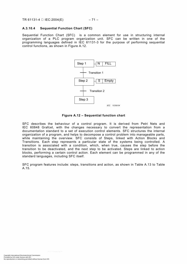
TR 61131-4 IEC:2004(E) – 71 –
A.3.10.4 Sequential Function Chart (SFC)
Sequential Function Chart (SFC) is a common element for use in structuring internal organization of a PLC program organization unit. SFC can be written in one of the programming languages defined in IEC 61131-3 for the purpose of performing sequential control functions, as shown in Figure A.12.
Step 1 N FILL
Step 3
Step 2 S Empty
Transition 1
Transition 2
Figure A.12 – Sequential function chart
SFC describes the behaviour of a control program. It is derived from Petri Nets and IEC 60848 Grafcet, with the changes necessary to convert the representation from a documentation standard to a set of execution control elements. SFC structures the internal organization of a program, and helps to decompose a control problem into manageable parts, while maintaining the overview. SFC consists of Steps, linked with Action Blocks and Transitions. Each step represents a particular state of the systems being controlled. A transition is associated with a condition, which, when true, causes the step before the transition to be deactivated, and the next step to be activated. Steps are linked to action blocks, performing a certain control action. Each element can be programmed in any of the standard languages, including SFC itself.
SFC program features include: steps, transitions and action, as shown in Table A.13 to Table A.15.
IEC 1036/04
Copyright International Electrotechnical Commission Provided by IHS under license with IEC
Not for ResaleNo reproduction or networking permitted without license from IHS
--``````-`-`,,`,,`,`,,`---
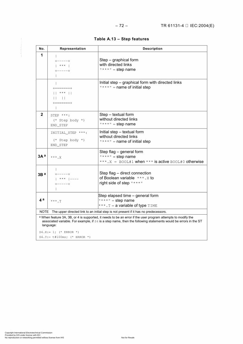
– 72 – TR 61131-4 IEC:2004(E)
Table A.13 – Step features
No. Representation Description
1 |
+-----+
| *** |
+-----+
|
Step – graphical form with directed links "***" = step name
|
+=======+
|| *** ||
|| ||
+=======+
|
Initial step – graphical form with directed links "***" = name of initial step
2 STEP ***:
(* Step body *)
END_STEP
Step – textual form without directed links "***" = step name
INITIAL_STEP ***:
(* Step body *)
END_STEP
Initial step – textual form without directed links "***" = name of initial step
3A a
***.X
Step flag – general form "***" = step name ***.X = BOOL#1 when *** is active BOOL#0 otherwise
3B a
|
+-----+
| *** |----
+-----+
|
Step flag – direct connection of Boolean variable ***.X to right side of step "***"
4 a
***.T
Step elapsed time – general form "***" = step name ***.T = a variable of type TIME
NOTE The upper directed link to an initial step is not present if it has no predecessors. a When feature 3A, 3B, or 4 is supported, it needs to be an error if the user program attempts to modify the
associated variable. For example, if S4 is a step name, then the following statements would be errors in the ST language:
S4.X:= 1; (* ERROR *)
S4.T:= t#100ms; (* ERROR *)
Copyright International Electrotechnical Commission Provided by IHS under license with IEC
Not for ResaleNo reproduction or networking permitted without license from IHS
--``````-`-`,,`,,`,`,,`---
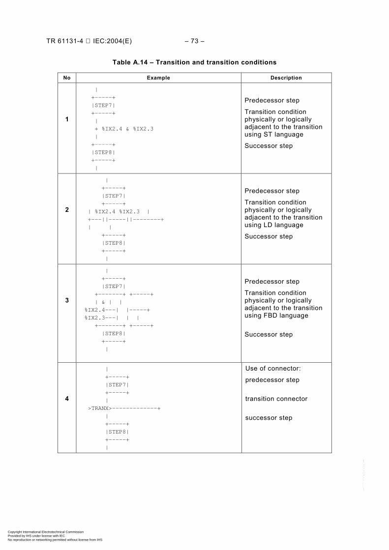
TR 61131-4 IEC:2004(E) – 73 –
Table A.14 – Transition and transition conditions
No Example Description
1
|
+-----+
|STEP7|
+-----+
|
+ %IX2.4 & %IX2.3
|
+-----+
|STEP8|
+-----+
|
Predecessor step
Transition condition physically or logically adjacent to the transition using ST language
Successor step
2
|
+-----+
|STEP7|
+-----+
| %IX2.4 %IX2.3 |
+---||-----||--------+
| |
+-----+
|STEP8|
+-----+
|
Predecessor step
Transition condition physically or logically adjacent to the transition using LD language
Successor step
3
|
+-----+
|STEP7|
+-------+ +-----+
| & | |
%IX2.4---| |-----+
%IX2.3---| | |
+-------+ +-----+
|STEP8|
+-----+
|
Predecessor step
Transition condition physically or logically adjacent to the transition using FBD language
Successor step
4
|
+-----+
|STEP7|
+-----+
|
>TRANX>-------------+
|
+-----+
|STEP8|
+-----+
|
Use of connector:
predecessor step
transition connector
successor step
Copyright International Electrotechnical Commission Provided by IHS under license with IEC
Not for ResaleNo reproduction or networking permitted without license from IHS
--``````-`-`,,`,,`,`,,`---
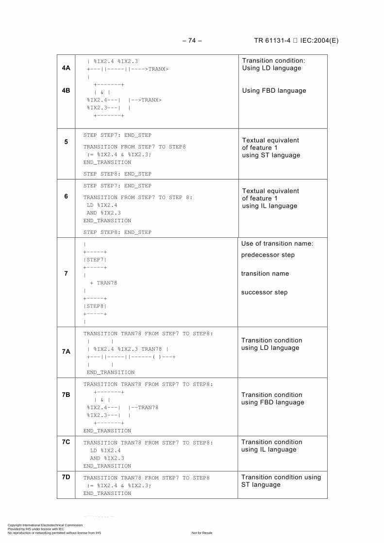
– 74 – TR 61131-4 IEC:2004(E)
4A
4B
| %IX2.4 %IX2.3
+---||-----||---->TRANX>
|
+-------+
| & |
%IX2.4---| |-->TRANX>
%IX2.3---| |
+-------+
Transition condition: Using LD language
Using FBD language
5
STEP STEP7: END_STEP
TRANSITION FROM STEP7 TO STEP8
:= %IX2.4 & %IX2.3;
END_TRANSITION
STEP STEP8: END_STEP
Textual equivalent of feature 1 using ST language
6
STEP STEP7: END_STEP
TRANSITION FROM STEP7 TO STEP 8:
LD %IX2.4
AND %IX2.3
END_TRANSITION
STEP STEP8: END_STEP
Textual equivalent of feature 1 using IL language
7
|
+-----+
|STEP7|
+-----+
|
+ TRAN78
|
+-----+
|STEP8|
+-----+
|
Use of transition name:
predecessor step
transition name
successor step
7A
TRANSITION TRAN78 FROM STEP7 TO STEP8:
| |
| %IX2.4 %IX2.3 TRAN78 |
+---||-----||------( )---+
| |
END_TRANSITION
Transition condition using LD language
7B
TRANSITION TRAN78 FROM STEP7 TO STEP8:
+-------+
| & |
%IX2.4---| |--TRAN78
%IX2.3---| |
+-------+
END_TRANSITION
Transition condition using FBD language
7C
TRANSITION TRAN78 FROM STEP7 TO STEP8:
LD %IX2.4
AND %IX2.3
END_TRANSITION
Transition condition using IL language
7D TRANSITION TRAN78 FROM STEP7 TO STEP8
:= %IX2.4 & %IX2.3;
END_TRANSITION
Transition condition using ST language
Copyright International Electrotechnical Commission Provided by IHS under license with IEC
Not for ResaleNo reproduction or networking permitted without license from IHS
--``````-`-`,,`,,`,`,,`---
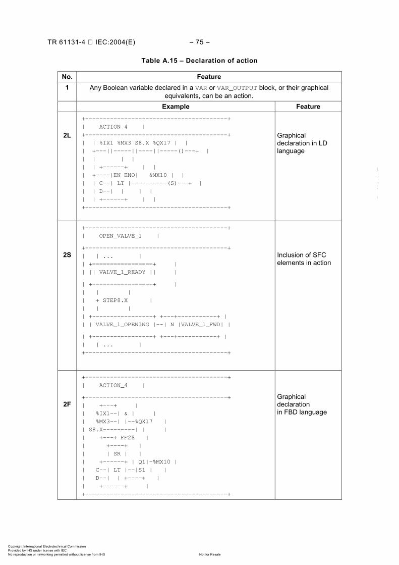
TR 61131-4 IEC:2004(E) – 75 –
Table A.15 – Declaration of action
No. Feature 1 Any Boolean variable declared in a VAR or VAR_OUTPUT block, or their graphical
equivalents, can be an action. Example Feature
2L
+----------------------------------------+
| ACTION_4 |
+----------------------------------------+
| | %IX1 %MX3 S8.X %QX17 | |
| +---||-----||----||-----()---+ |
| | | |
| | +------+ | |
| +----|EN ENO| %MX10 | |
| | C--| LT |----------(S)---+ |
| | D--| | | |
| | +------+ | |
+----------------------------------------+
Graphical declaration in LD language
2S
+----------------------------------------+
| OPEN_VALVE_1 |
+----------------------------------------+
| | ... |
| +=================+ |
| || VALVE_1_READY || |
| +=================+ |
| | |
| + STEP8.X |
| | |
| +-----------------+ +---+-----------+ |
| | VALVE_1_OPENING |--| N |VALVE_1_FWD| |
| +-----------------+ +---+-----------+ |
| | ... |
+----------------------------------------+
Inclusion of SFC elements in action
2F
+----------------------------------------+
| ACTION_4 |
+----------------------------------------+
| +---+ |
| %IX1--| & | |
| %MX3--| |--%QX17 |
| S8.X---------| | |
| +---+ FF28 |
| +----+ |
| | SR | |
| +------+ | Q1|-%MX10 |
| C--| LT |--|S1 | |
| D--| | +----+ |
| +------+ |
+----------------------------------------+
Graphical declaration in FBD language
Copyright International Electrotechnical Commission Provided by IHS under license with IEC
Not for ResaleNo reproduction or networking permitted without license from IHS
--``````-`-`,,`,,`,`,,`---
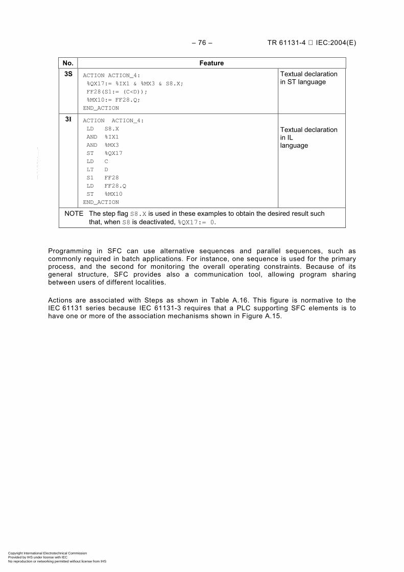
– 76 – TR 61131-4 IEC:2004(E)
No. Feature 3S
ACTION ACTION_4:
%QX17:= %IX1 & %MX3 & S8.X;
FF28(S1:= (C<D));
%MX10:= FF28.Q;
END_ACTION
Textual declaration in ST language
3I
ACTION ACTION_4:
LD S8.X
AND %IX1
AND %MX3
ST %QX17
LD C
LT D
S1 FF28
LD FF28.Q
ST %MX10
END_ACTION
Textual declaration in IL language
NOTE The step flag S8.X is used in these examples to obtain the desired result such that, when S8 is deactivated, %QX17:= 0.
Programming in SFC can use alternative sequences and parallel sequences, such as commonly required in batch applications. For instance, one sequence is used for the primary process, and the second for monitoring the overall operating constraints. Because of its general structure, SFC provides also a communication tool, allowing program sharing between users of different localities.
Actions are associated with Steps as shown in Table A.16. This figure is normative to the IEC 61131 series because IEC 61131-3 requires that a PLC supporting SFC elements is to have one or more of the association mechanisms shown in Figure A.15.
Copyright International Electrotechnical Commission Provided by IHS under license with IEC
Not for ResaleNo reproduction or networking permitted without license from IHS
--``````-`-`,,`,,`,`,,`---

TR 61131-4 IEC:2004(E) – 77 –
Table A.16 – Step/action association
No. Example Feature
1
|
+----+ +-----+----------+---+
| S8 |--| L | ACTION_1 |DN1|
+----+ |t#10s| | |
| +-----+----------+---+
+ DN1
|
Action block physically or logically adjacent to the step
2
|
+----+ +-----+---------------------+---+
| S8 |--| L | ACTION_1 |DN1|
+----+ |t#10s| | |
| +-----+---------------------+---+
+DN1 | P | ACTION_2 | |
| +-----+---------------------+---+
| | N | ACTION_3 | |
| +-----+---------------------+---+
Concatenated action blocks physically or logically adjacent to the step
3
STEP S8:
ACTION_1(L,t#10s,DN1);
ACTION_2(P);
ACTION_3(N);
END_STEP
Textual step body
4 a
+-----+----------------------+---+
----| N | ACTION_4 | |---
+-----+----------------------+---+
| %QX17:= %IX1 & %MX3 & S8.X; |
| FF28 (S1:= (C<D)); |
| %MX10:= FF28.Q; |
+--------------------------------+
Action block "d" field
a When feature 4 is used, the corresponding action name cannot be used in any other action block.
Copyright International Electrotechnical Commission Provided by IHS under license with IEC
Not for ResaleNo reproduction or networking permitted without license from IHS
--``````-`-`,,`,,`,`,,`---
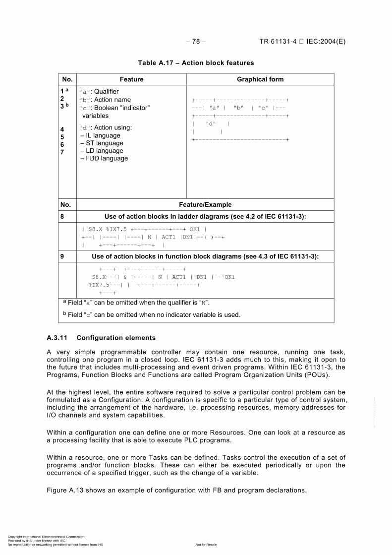
– 78 – TR 61131-4 IEC:2004(E)
Table A.17 – Action block features
No. Feature Graphical form
1 a 2 3 b
4 5 6 7
"a": Qualifier "b": Action name "c": Boolean "indicator" variables
"d": Action using: – IL language – ST language – LD language – FBD language
+-----+--------------+-----+
---| "a" | "b" | "c" |---
+-----+--------------+-----+
| "d" |
| |
+--------------------------+
No. Feature/Example
8 Use of action blocks in ladder diagrams (see 4.2 of IEC 61131-3):
| S8.X %IX7.5 +---+------+---+ OK1 |
+--| |----| |----| N | ACT1 |DN1|--( )--+
| +---+------+---+ |
9 Use of action blocks in function block diagrams (see 4.3 of IEC 61131-3):
+---+ +---+------+-----+
S8.X---| & |-----| N | ACT1 | DN1 |---OK1
%IX7.5---| | +---+------+-----+
+---+
a Field “a” can be omitted when the qualifier is “N”. b Field “c” can be omitted when no indicator variable is used.
A.3.11 Configuration elements
A very simple programmable controller may contain one resource, running one task, controlling one program in a closed loop. IEC 61131-3 adds much to this, making it open to the future that includes multi-processing and event driven programs. Within IEC 61131-3, the Programs, Function Blocks and Functions are called Program Organization Units (POUs).
At the highest level, the entire software required to solve a particular control problem can be formulated as a Configuration. A configuration is specific to a particular type of control system, including the arrangement of the hardware, i.e. processing resources, memory addresses for I/O channels and system capabilities.
Within a configuration one can define one or more Resources. One can look at a resource as a processing facility that is able to execute PLC programs.
Within a resource, one or more Tasks can be defined. Tasks control the execution of a set of programs and/or function blocks. These can either be executed periodically or upon the occurrence of a specified trigger, such as the change of a variable.
Figure A.13 shows an example of configuration with FB and program declarations.
Copyright International Electrotechnical Commission Provided by IHS under license with IEC
Not for ResaleNo reproduction or networking permitted without license from IHS
--``````-`-`,,`,,`,`,,`---
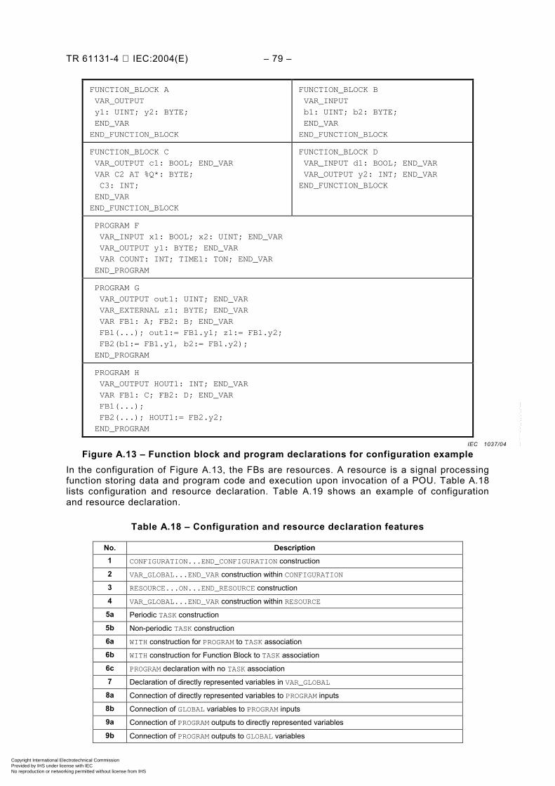
TR 61131-4 IEC:2004(E) – 79 –
FUNCTION_BLOCK A
VAR_OUTPUT
y1: UINT; y2: BYTE;
END_VAR
END_FUNCTION_BLOCK
FUNCTION_BLOCK B
VAR_INPUT
b1: UINT; b2: BYTE;
END_VAR
END_FUNCTION_BLOCK
FUNCTION_BLOCK C
VAR_OUTPUT c1: BOOL; END_VAR
VAR C2 AT %Q*: BYTE;
C3: INT;
END_VAR
END_FUNCTION_BLOCK
FUNCTION_BLOCK D
VAR_INPUT d1: BOOL; END_VAR
VAR_OUTPUT y2: INT; END_VAR
END_FUNCTION_BLOCK
PROGRAM F
VAR_INPUT x1: BOOL; x2: UINT; END_VAR
VAR_OUTPUT y1: BYTE; END_VAR
VAR COUNT: INT; TIME1: TON; END_VAR
END_PROGRAM
PROGRAM G
VAR_OUTPUT out1: UINT; END_VAR
VAR_EXTERNAL z1: BYTE; END_VAR
VAR FB1: A; FB2: B; END_VAR
FB1(...); out1:= FB1.y1; z1:= FB1.y2;
FB2(b1:= FB1.y1, b2:= FB1.y2);
END_PROGRAM
PROGRAM H
VAR_OUTPUT HOUT1: INT; END_VAR
VAR FB1: C; FB2: D; END_VAR
FB1(...);
FB2(...); HOUT1:= FB2.y2;
END_PROGRAM
Figure A.13 – Function block and program declarations for configuration example In the configuration of Figure A.13, the FBs are resources. A resource is a signal processing function storing data and program code and execution upon invocation of a POU. Table A.18 lists configuration and resource declaration. Table A.19 shows an example of configuration and resource declaration.
Table A.18 – Configuration and resource declaration features
No. Description 1 CONFIGURATION...END_CONFIGURATION construction
2 VAR_GLOBAL...END_VAR construction within CONFIGURATION
3 RESOURCE...ON...END_RESOURCE construction
4 VAR_GLOBAL...END_VAR construction within RESOURCE
5a Periodic TASK construction
5b Non-periodic TASK construction
6a WITH construction for PROGRAM to TASK association
6b WITH construction for Function Block to TASK association
6c PROGRAM declaration with no TASK association
7 Declaration of directly represented variables in VAR_GLOBAL
8a Connection of directly represented variables to PROGRAM inputs
8b Connection of GLOBAL variables to PROGRAM inputs
9a Connection of PROGRAM outputs to directly represented variables
9b Connection of PROGRAM outputs to GLOBAL variables
IEC 1037/04
Copyright International Electrotechnical Commission Provided by IHS under license with IEC
Not for ResaleNo reproduction or networking permitted without license from IHS
--``````-`-`,,`,,`,`,,`---
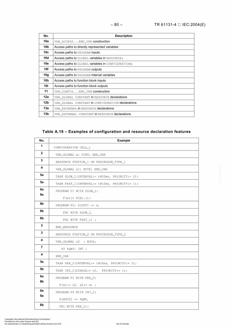
– 80 – TR 61131-4 IEC:2004(E)
No. Description 10a VAR_ACCESS...END_VAR construction
10b Access paths to directly represented variables
10c Access paths to PROGRAM inputs
10d Access paths to GLOBAL variables in RESOURCEs
10e Access paths to GLOBAL variables in CONFIGURATIONs
10f Access paths to PROGRAM outputs
10g Access paths to PROGRAM internal variables
10h Access paths to function block inputs
10i Access paths to function block outputs
11 VAR_CONFIG...END_VAR construction
12a VAR_GLOBAL CONSTANT in RESOURCE declarations
12b VAR_GLOBAL CONSTANT in CONFIGURATION declarations
13a VAR_EXTERNAL in RESOURCE declarations
13b VAR_EXTERNAL CONSTANT in RESOURCE declarations
Table A.19 – Examples of configuration and resource declaration features
No. Example 1 CONFIGURATION CELL_1
2 VAR_GLOBAL w: UINT; END_VAR
3 RESOURCE STATION_1 ON PROCESSOR_TYPE_1
4 VAR_GLOBAL z1: BYTE; END_VAR
5a TASK SLOW_1(INTERVAL:= t#20ms, PRIORITY:= 2);
5a TASK FAST_1(INTERVAL:= t#10ms, PRIORITY:= 1);
6a 8a
PROGRAM P1 WITH SLOW_1:
F(x1:= %IX1.1);
9b PROGRAM P2: G(OUT1 => w,
6b FB1 WITH SLOW_1,
6b FB2 WITH FAST_1) ;
3 END_RESOURCE
3 RESOURCE STATION_2 ON PROCESSOR_TYPE_2
4 VAR_GLOBAL z2 : BOOL;
7 AT %QW5: INT ;
4 END_VAR
5a TASK PER_2(INTERVAL:= t#50ms, PRIORITY:= 2);
5b TASK INT_2(SINGLE:= z2, PRIORITY:= 1);
6a 8b
PROGRAM P1 WITH PER_2:
F(x1:= z2, x2:= w) ;
6a 9a
PROGRAM P4 WITH INT_2:
H(HOUT1 => %QW5,
6b FB1 WITH PER_2);
Copyright International Electrotechnical Commission Provided by IHS under license with IEC
Not for ResaleNo reproduction or networking permitted without license from IHS
--``````-`-`,,`,,`,`,,`---
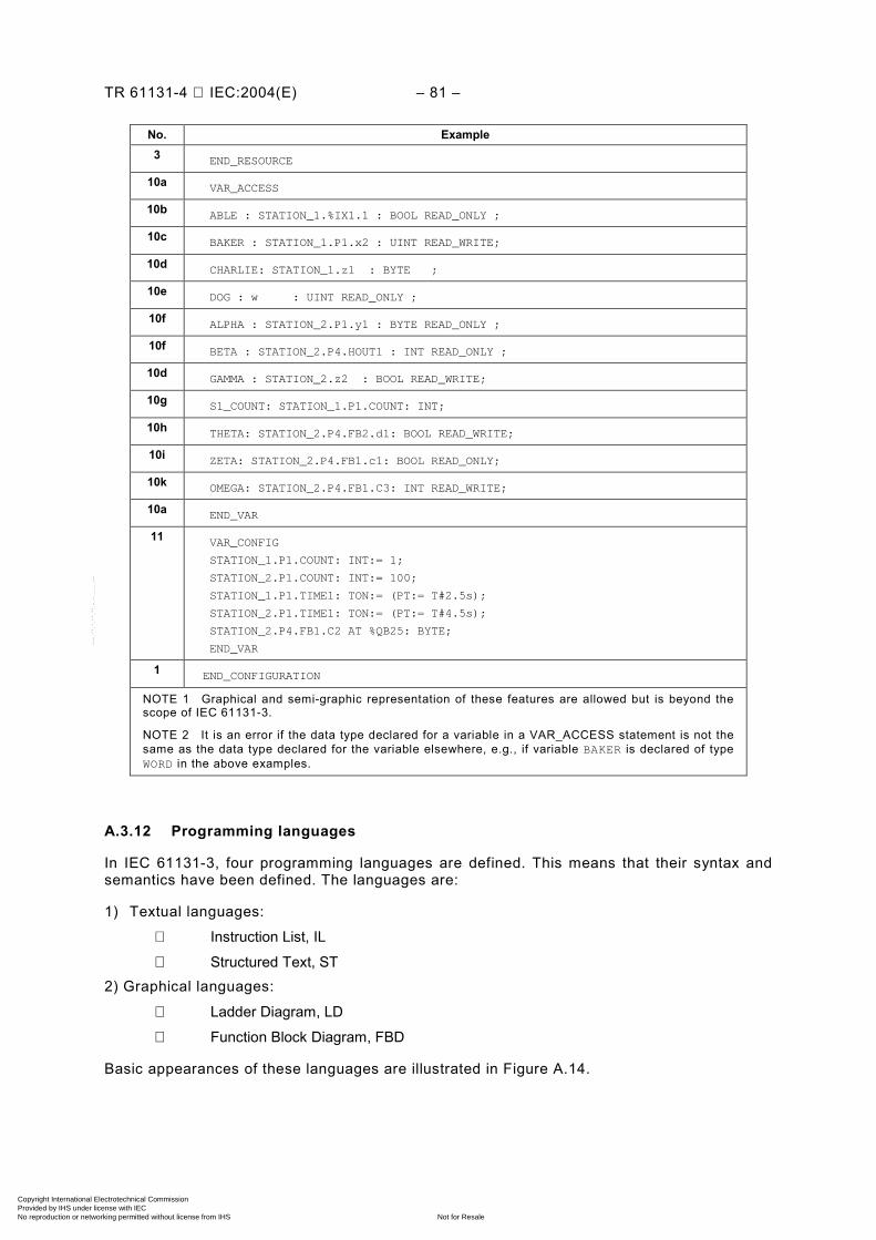
TR 61131-4 IEC:2004(E) – 81 –
No. Example 3 END_RESOURCE
10a VAR_ACCESS
10b ABLE : STATION_1.%IX1.1 : BOOL READ_ONLY ;
10c BAKER : STATION_1.P1.x2 : UINT READ_WRITE;
10d CHARLIE: STATION_1.z1 : BYTE ;
10e DOG : w : UINT READ_ONLY ;
10f ALPHA : STATION_2.P1.y1 : BYTE READ_ONLY ;
10f BETA : STATION_2.P4.HOUT1 : INT READ_ONLY ;
10d GAMMA : STATION_2.z2 : BOOL READ_WRITE;
10g S1_COUNT: STATION_1.P1.COUNT: INT;
10h THETA: STATION_2.P4.FB2.d1: BOOL READ_WRITE;
10i ZETA: STATION_2.P4.FB1.c1: BOOL READ_ONLY;
10k OMEGA: STATION_2.P4.FB1.C3: INT READ_WRITE;
10a END_VAR
11 VAR_CONFIG
STATION_1.P1.COUNT: INT:= 1;
STATION_2.P1.COUNT: INT:= 100;
STATION_1.P1.TIME1: TON:= (PT:= T#2.5s);
STATION_2.P1.TIME1: TON:= (PT:= T#4.5s);
STATION_2.P4.FB1.C2 AT %QB25: BYTE;
END_VAR
1 END_CONFIGURATION
NOTE 1 Graphical and semi-graphic representation of these features are allowed but is beyond the scope of IEC 61131-3.
NOTE 2 It is an error if the data type declared for a variable in a VAR_ACCESS statement is not the same as the data type declared for the variable elsewhere, e.g., if variable BAKER is declared of type WORD in the above examples.
A.3.12 Programming languages
In IEC 61131-3, four programming languages are defined. This means that their syntax and semantics have been defined. The languages are:
1) Textual languages:
Instruction List, IL
Structured Text, ST 2) Graphical languages:
Ladder Diagram, LD
Function Block Diagram, FBD
Basic appearances of these languages are illustrated in Figure A.14.
Copyright International Electrotechnical Commission Provided by IHS under license with IEC
Not for ResaleNo reproduction or networking permitted without license from IHS
--``````-`-`,,`,,`,`,,`---
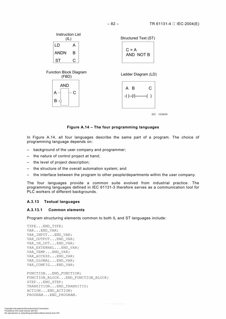
– 82 – TR 61131-4 IEC:2004(E)
Instruction List (IL) Structured Text (ST)
Function Block Diagram (FBD) Ladder Diagram (LD)
LD A
ANDN B
ST C
C = A AND NOT B
A B C
-| |--|/|--------( )
AND
A C
B
Figure A.14 – The four programming languages
In Figure A.14, all four languages describe the same part of a program. The choice of programming language depends on:
– background of the user company and programmer; – the nature of control project at hand; – the level of project description; – the structure of the overall automation system; and – the interface between the program to other people/departments within the user company.
The four languages provide a common suite evolved from industrial practice. The programming languages defined in IEC 61131-3 therefore serves as a communication tool for PLC workers of different backgrounds.
A.3.13 Textual languages
A.3.13.1 Common elements
Program structuring elements common to both IL and ST languages include:
TYPE...END_TYPE; VAR...END_VAR; VAR_INPUT...END_VAR; VAR_OUTPUT...END_VAR; VAR_IN_OUT...END_VAR; VAR_EXTERNAL...END_VAR; VAR_TEMP...END_VAR; VAR_ACCESS...END_VAR; VAR_GLOBAL...END_VAR; VAR_CONFIG...END_VAR; FUNCTION...END_FUNCTION; FUNCTION_BLOCK...END_FUNCTION_BLOCK; STEP...END_STEP; TRANSITION...END_TRANSITIO; ACTION...END_ACTION; PROGRAM...END_PROGRAM.
IEC 1038/04
Copyright International Electrotechnical Commission Provided by IHS under license with IEC
Not for ResaleNo reproduction or networking permitted without license from IHS
--``````-`-`,,`,,`,`,,`---
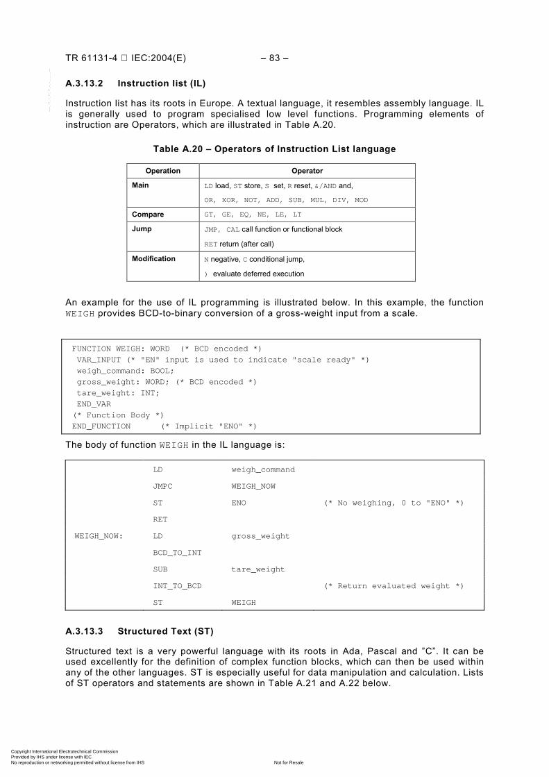
TR 61131-4 IEC:2004(E) – 83 –
A.3.13.2 Instruction list (IL)
Instruction list has its roots in Europe. A textual language, it resembles assembly language. IL is generally used to program specialised low level functions. Programming elements of instruction are Operators, which are illustrated in Table A.20.
Table A.20 – Operators of Instruction List language
Operation Operator
Main LD load, ST store, S set, R reset, &/AND and,
OR, XOR, NOT, ADD, SUB, MUL, DIV, MOD
Compare GT, GE, EQ, NE, LE, LT
Jump JMP, CAL call function or functional block
RET return (after call)
Modification N negative, C conditional jump,
) evaluate deferred execution
An example for the use of IL programming is illustrated below. In this example, the function WEIGH provides BCD-to-binary conversion of a gross-weight input from a scale.
FUNCTION WEIGH: WORD (* BCD encoded *)
VAR_INPUT (* "EN" input is used to indicate "scale ready" *)
weigh_command: BOOL;
gross_weight: WORD; (* BCD encoded *)
tare_weight: INT;
END_VAR
(* Function Body *)
END_FUNCTION (* Implicit "ENO" *)
The body of function WEIGH in the IL language is:
LD weigh_command
JMPC WEIGH_NOW
ST ENO (* No weighing, 0 to "ENO" *)
RET
WEIGH_NOW: LD gross_weight
BCD_TO_INT
SUB tare_weight
INT_TO_BCD (* Return evaluated weight *)
ST WEIGH
A.3.13.3 Structured Text (ST)
Structured text is a very powerful language with its roots in Ada, Pascal and ”C”. It can be used excellently for the definition of complex function blocks, which can then be used within any of the other languages. ST is especially useful for data manipulation and calculation. Lists of ST operators and statements are shown in Table A.21 and A.22 below.
Copyright International Electrotechnical Commission Provided by IHS under license with IEC
Not for ResaleNo reproduction or networking permitted without license from IHS
--``````-`-`,,`,,`,`,,`---
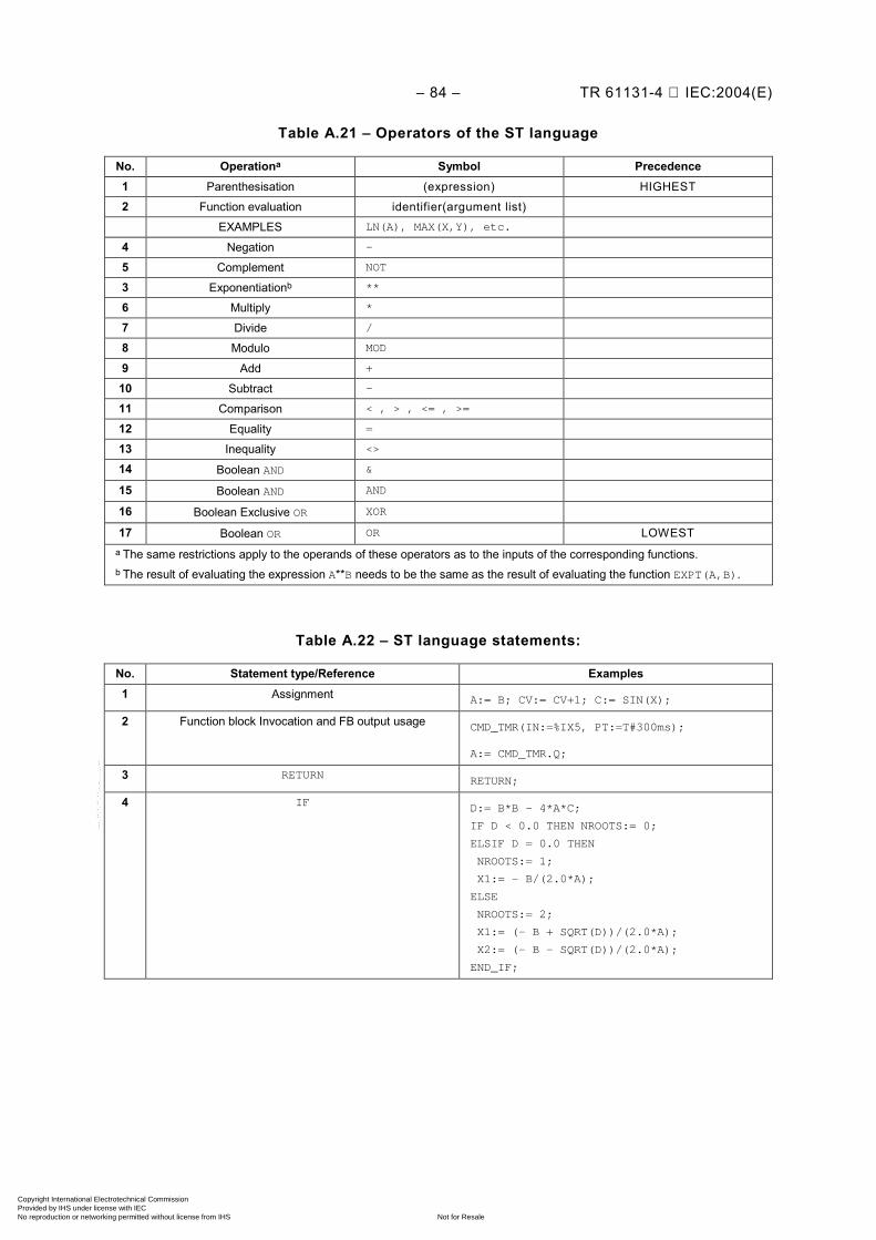
– 84 – TR 61131-4 IEC:2004(E)
Table A.21 – Operators of the ST language
No. Operationa Symbol Precedence 1 Parenthesisation (expression) HIGHEST
2 Function evaluation identifier(argument list)
EXAMPLES LN(A), MAX(X,Y), etc.
4 Negation -
5 Complement NOT
3 Exponentiationb **
6 Multiply *
7 Divide /
8 Modulo MOD
9 Add +
10 Subtract -
11 Comparison < , > , <= , >=
12 Equality =
13 Inequality <>
14 Boolean AND &
15 Boolean AND AND
16 Boolean Exclusive OR XOR
17 Boolean OR OR LOWEST a The same restrictions apply to the operands of these operators as to the inputs of the corresponding functions.
b The result of evaluating the expression A**B needs to be the same as the result of evaluating the function EXPT(A,B).
Table A.22 – ST language statements:
No. Statement type/Reference Examples 1 Assignment A:= B; CV:= CV+1; C:= SIN(X);
2
Function block Invocation and FB output usage CMD_TMR(IN:=%IX5, PT:=T#300ms);
A:= CMD_TMR.Q;
3 RETURN RETURN;
4
IF
D:= B*B – 4*A*C;
IF D < 0.0 THEN NROOTS:= 0;
ELSIF D = 0.0 THEN
NROOTS:= 1;
X1:= – B/(2.0*A);
ELSE
NROOTS:= 2;
X1:= (- B + SQRT(D))/(2.0*A);
X2:= (- B – SQRT(D))/(2.0*A);
END_IF;
Copyright International Electrotechnical Commission Provided by IHS under license with IEC
Not for ResaleNo reproduction or networking permitted without license from IHS
--``````-`-`,,`,,`,`,,`---
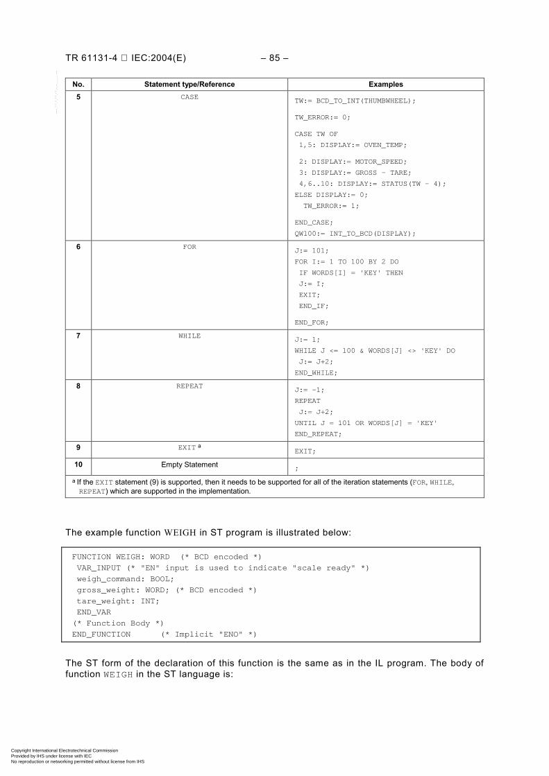
TR 61131-4 IEC:2004(E) – 85 –
No. Statement type/Reference Examples 5 CASE TW:= BCD_TO_INT(THUMBWHEEL);
TW_ERROR:= 0;
CASE TW OF
1,5: DISPLAY:= OVEN_TEMP;
2: DISPLAY:= MOTOR_SPEED;
3: DISPLAY:= GROSS – TARE;
4,6..10: DISPLAY:= STATUS(TW – 4);
ELSE DISPLAY:= 0;
TW_ERROR:= 1;
END_CASE;
QW100:= INT_TO_BCD(DISPLAY);
6 FOR J:= 101;
FOR I:= 1 TO 100 BY 2 DO
IF WORDS[I] = 'KEY' THEN
J:= I;
EXIT;
END_IF;
END_FOR;
7 WHILE J:= 1;
WHILE J <= 100 & WORDS[J] <> 'KEY' DO
J:= J+2;
END_WHILE;
8 REPEAT J:= -1;
REPEAT
J:= J+2;
UNTIL J = 101 OR WORDS[J] = 'KEY'
END_REPEAT;
9 EXIT a EXIT;
10 Empty Statement ;
a If the EXIT statement (9) is supported, then it needs to be supported for all of the iteration statements (FOR, WHILE, REPEAT) which are supported in the implementation.
The example function WEIGH in ST program is illustrated below:
FUNCTION WEIGH: WORD (* BCD encoded *)
VAR_INPUT (* "EN" input is used to indicate "scale ready" *)
weigh_command: BOOL;
gross_weight: WORD; (* BCD encoded *)
tare_weight: INT;
END_VAR
(* Function Body *)
END_FUNCTION (* Implicit "ENO" *)
The ST form of the declaration of this function is the same as in the IL program. The body of function WEIGH in the ST language is:
Copyright International Electrotechnical Commission Provided by IHS under license with IEC
Not for ResaleNo reproduction or networking permitted without license from IHS
--``````-`-`,,`,,`,`,,`---
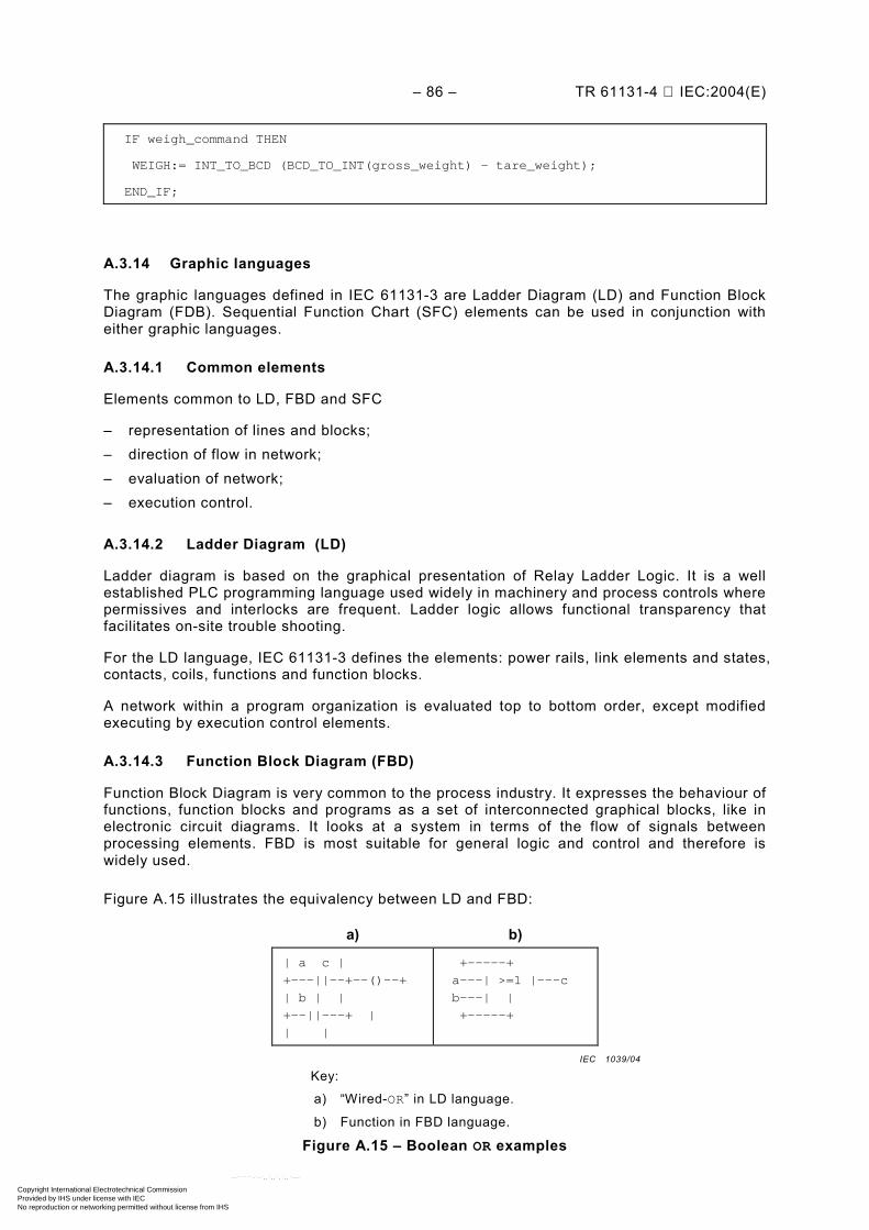
– 86 – TR 61131-4 IEC:2004(E)
IF weigh_command THEN
WEIGH:= INT_TO_BCD (BCD_TO_INT(gross_weight) – tare_weight);
END_IF;
A.3.14 Graphic languages
The graphic languages defined in IEC 61131-3 are Ladder Diagram (LD) and Function Block Diagram (FDB). Sequential Function Chart (SFC) elements can be used in conjunction with either graphic languages.
A.3.14.1 Common elements
Elements common to LD, FBD and SFC
– representation of lines and blocks; – direction of flow in network; – evaluation of network; – execution control.
A.3.14.2 Ladder Diagram (LD)
Ladder diagram is based on the graphical presentation of Relay Ladder Logic. It is a well established PLC programming language used widely in machinery and process controls where permissives and interlocks are frequent. Ladder logic allows functional transparency that facilitates on-site trouble shooting.
For the LD language, IEC 61131-3 defines the elements: power rails, link elements and states, contacts, coils, functions and function blocks.
A network within a program organization is evaluated top to bottom order, except modified executing by execution control elements.
A.3.14.3 Function Block Diagram (FBD)
Function Block Diagram is very common to the process industry. It expresses the behaviour of functions, function blocks and programs as a set of interconnected graphical blocks, like in electronic circuit diagrams. It looks at a system in terms of the flow of signals between processing elements. FBD is most suitable for general logic and control and therefore is widely used.
Figure A.15 illustrates the equivalency between LD and FBD:
a) b)
| a c |
+---||--+--()--+
| b | |
+--||---+ |
| |
+-----+
a---| >=1 |---c
b---| |
+-----+
Key:
a) “Wired-OR” in LD language.
b) Function in FBD language.
Figure A.15 – Boolean OR examples
IEC 1039/04
Copyright International Electrotechnical Commission Provided by IHS under license with IEC
Not for ResaleNo reproduction or networking permitted without license from IHS
--``````-`-`,,`,,`,`,,`---
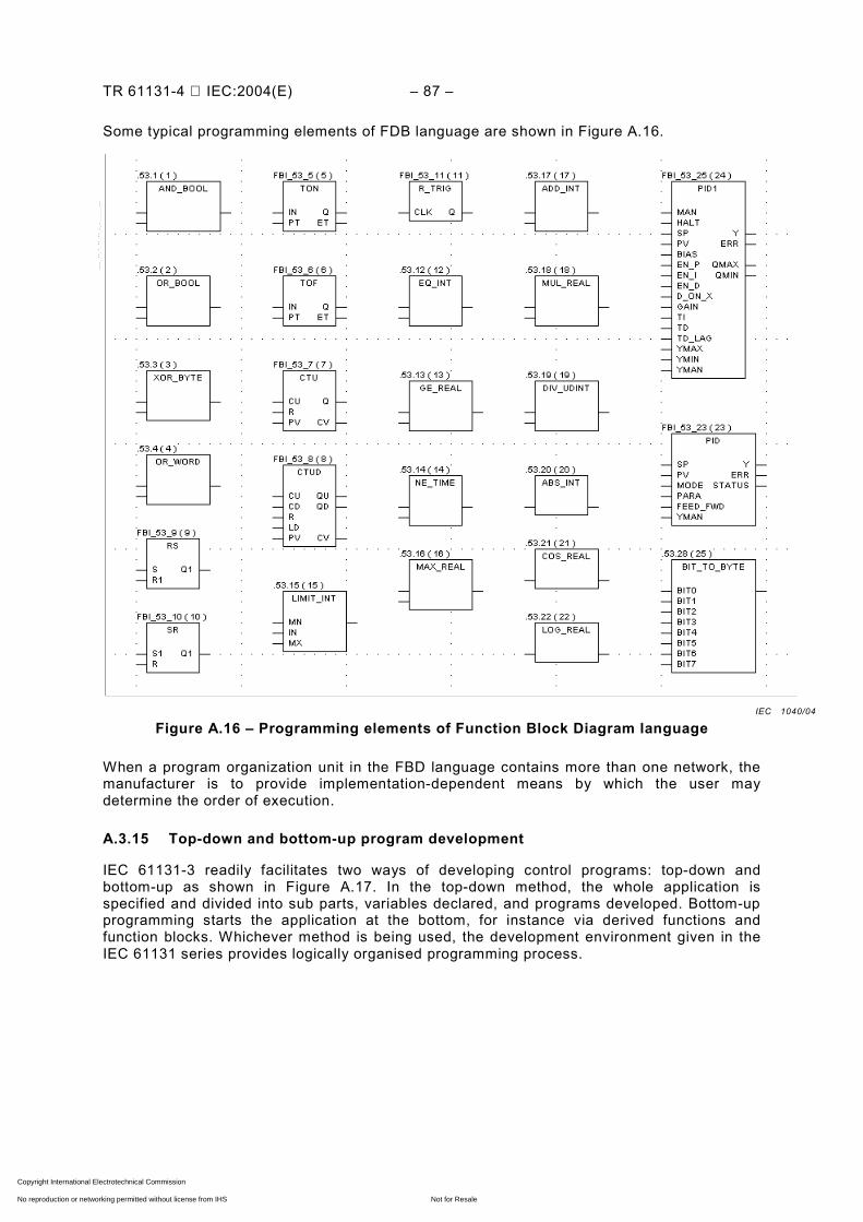
TR 61131-4 IEC:2004(E) – 87 –
Some typical programming elements of FDB language are shown in Figure A.16.
Figure A.16 – Programming elements of Function Block Diagram language
When a program organization unit in the FBD language contains more than one network, the manufacturer is to provide implementation-dependent means by which the user may determine the order of execution.
A.3.15 Top-down and bottom-up program development
IEC 61131-3 readily facilitates two ways of developing control programs: top-down and bottom-up as shown in Figure A.17. In the top-down method, the whole application is specified and divided into sub parts, variables declared, and programs developed. Bottom-up programming starts the application at the bottom, for instance via derived functions and function blocks. Whichever method is being used, the development environment given in the IEC 61131 series provides logically organised programming process.
IEC 1040/04
Copyright International Electrotechnical Commission Provided by IHS under license with IEC
Not for ResaleNo reproduction or networking permitted without license from IHS
--``````-`-`,,`,,`,`,,`---
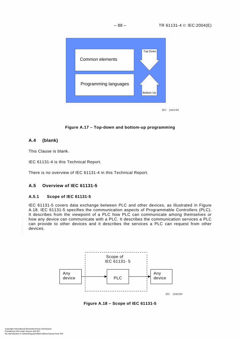
– 88 – TR 61131-4 © IEC:2004(E)
Common elements
Programming languages
Top Down
Bottom Up
Figure A.17 – Top-down and bottom-up programming
A.4 (blank)
This Clause is blank.
IEC 61131-4 is this Technical Report.
There is no overview of IEC 61131-4 in this Technical Report.
A.5 Overview of IEC 61131-5
A.5.1 Scope of IEC 61131-5
IEC 61131-5 covers data exchange between PLC and other devices, as illustrated in Figure A.18. IEC 61131-5 specifies the communication aspects of Programmable Controllers (PLC). It describes from the viewpoint of a PLC how PLC can communicate among themselves or how any device can communicate with a PLC. It describes the communication services a PLC can provide to other devices and it describes the services a PLC can request from other devices.
Figure A.18 – Scope of IEC 61131-5
Scope of IEC 61131- 5
Any device
Any device
PLC
IEC 1041/04
IEC 1042/04
Copyright International Electrotechnical Commission Provided by IHS under license with IEC
Not for ResaleNo reproduction or networking permitted without license from IHS
--``````-`-`,,`,,`,`,,`---
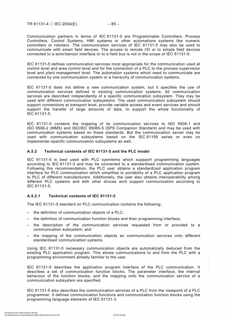
TR 61131-4 IEC:2004(E) – 89 –
Communication partners in terms of IEC 61131-5 are Programmable Controllers, Process Controllers, Control Systems, HMI systems or other automations systems like numeric controllers or roboters. The communication services of IEC 61131-5 may also be used to communicate with smart field devices. The access to remote I/O or to simple field devices connected to a actor/sensor interface or to a field bus is not in the scope of IEC 61131-5.
IEC 61131-5 defines communication services most appropriate for the communication used at control level and area control level and for the connection of a PLC to the process supervision level and plant management level. The automation systems which need to communicate are connected by one communication system or a hierarchy of communication systems.
IEC 61131-5 does not define a new communication system, but it specifies the use of communication services defined in existing communication systems. All communication services are described independently of a specific communication subsystem. They may be used with different communication subsystems. The used communication subsystem should support connections at transport level, provide variable access and event services and should support the transfer of large amounts of data, to support the whole functionality of IEC 61131-5.
IEC 61131-5 contains the mapping of its communication services to ISO 9506-1 and ISO 9506-2 (MMS) and ISO/IEC 95065-5 (SPS Companion Standard) and may be used with communication systems based on these standards. But the communication server may be used with communication subsystems based on the IEC 61158 series or even on implementer-specific communication subsystems as well.
A.5.2 Technical contents of IEC 61131-5 and the PLC model
IEC 61131-5 is best used with PLC sysmtems which suppport programming languages according to IEC 61131-3 and may be connected to a standardised communication system. Following this recommendation, the PLC user obtains a standardized application program interface for PLC communication which simplifies to portability of a PLC application program to PLC of different manufacturers. Additionally, the user also obtains interoperability among different PLC systems and with other divices wich support communication according to IEC 61131-5.
A.5.2.1 Technical contents of IEC 61131-5
The IEC 61131-5 standard on PLC communication contains the following:
– the definition of communication objects of a PLC; – the definition of communication function blocks and their programming interface; – the description of the communication services requested from or provided to a
communication subsystem; and – the mapping of the communication objects an communication services onto different
standardised communication systems.
Using IEC 61131-5 necessary communication objects are automatically deduced from the existing PLC application program. This allows communications to and from the PLC with a programming environment already familiar to the user.
IEC 61131-5 describes the application program interface of the PLC communication. It describes a set of communication function blocks. The parameter interface, the internal behaviour of the function blocks, and the mapping onto the communication service of a communication subsystem are specified.
IEC 61131-5 also describes the communication services of a PLC from the viewpoint of a PLC programmer. It defines communication functions and communication function blocks using the programming language elements of IEC 61131-3.
Copyright International Electrotechnical Commission Provided by IHS under license with IEC
Not for ResaleNo reproduction or networking permitted without license from IHS
--``````-`-`,,`,,`,`,,`---
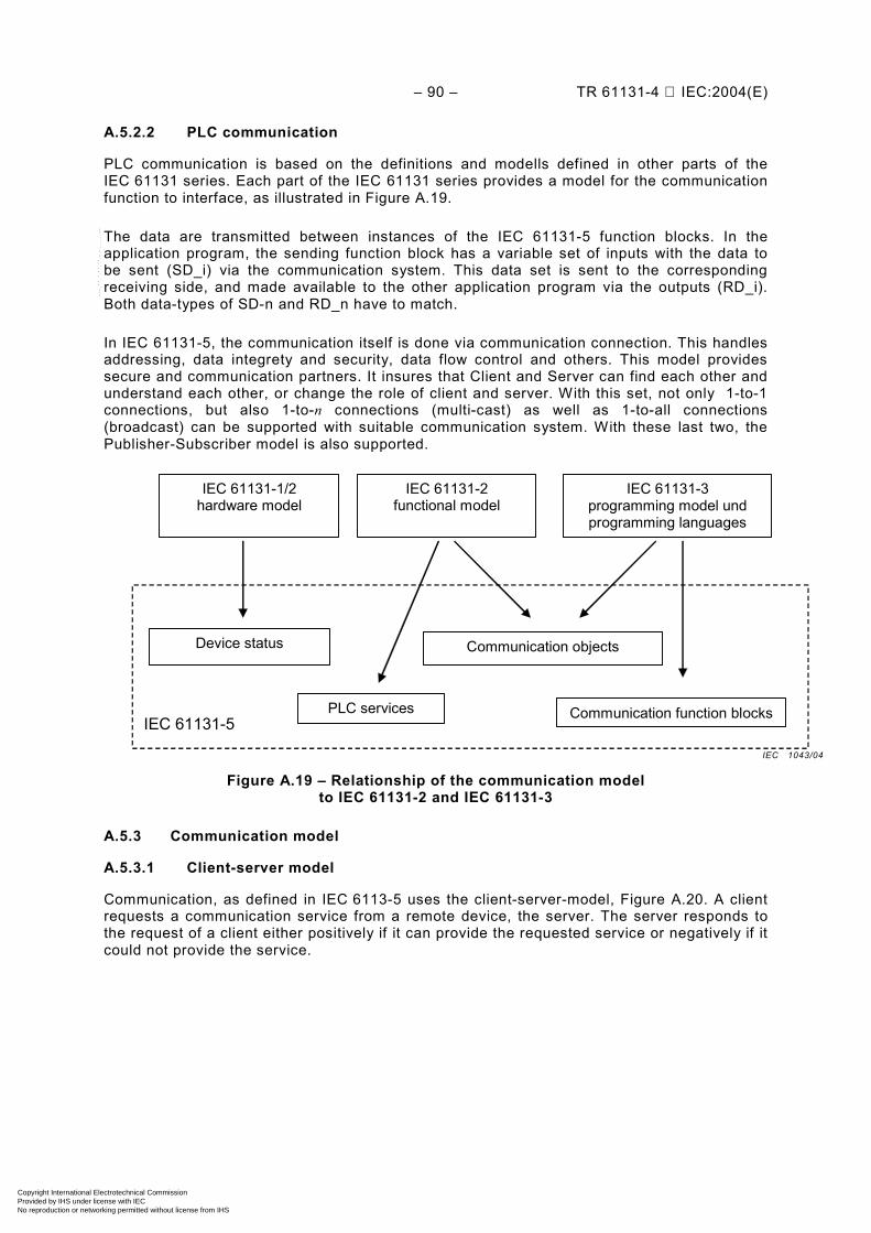
– 90 – TR 61131-4 IEC:2004(E)
A.5.2.2 PLC communication
PLC communication is based on the definitions and modells defined in other parts of the IEC 61131 series. Each part of the IEC 61131 series provides a model for the communication function to interface, as illustrated in Figure A.19.
The data are transmitted between instances of the IEC 61131-5 function blocks. In the application program, the sending function block has a variable set of inputs with the data to be sent (SD_i) via the communication system. This data set is sent to the corresponding receiving side, and made available to the other application program via the outputs (RD_i). Both data-types of SD-n and RD_n have to match.
In IEC 61131-5, the communication itself is done via communication connection. This handles addressing, data integrety and security, data flow control and others. This model provides secure and communication partners. It insures that Client and Server can find each other and understand each other, or change the role of client and server. With this set, not only 1-to-1 connections, but also 1-to-n connections (multi-cast) as well as 1-to-all connections (broadcast) can be supported with suitable communication system. With these last two, the Publisher-Subscriber model is also supported.
IEC 61131-5
IEC 61131-3 programming model und programming languages
IEC 61131-1/2 hardware model
IEC 61131-2 functional model
Communication function blocks
Device status
PLC services
Communication objects
Figure A.19 – Relationship of the communication model to IEC 61131-2 and IEC 61131-3
A.5.3 Communication model
A.5.3.1 Client-server model
Communication, as defined in IEC 6113-5 uses the client-server-model, Figure A.20. A client requests a communication service from a remote device, the server. The server responds to the request of a client either positively if it can provide the requested service or negatively if it could not provide the service.
IEC 1043/04
Copyright International Electrotechnical Commission Provided by IHS under license with IEC
Not for ResaleNo reproduction or networking permitted without license from IHS
--``````-`-`,,`,,`,`,,`---
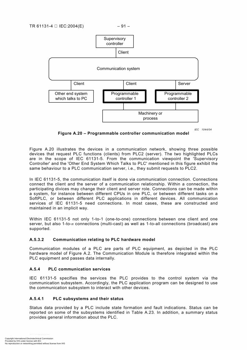
TR 61131-4 IEC:2004(E) – 91 –
Communication system
Supervisorycontroller
Other end system which talks to PC
Programmablecontroller 1
Programmable controller 2
Client
Client Client Server
Machinery or process
Figure A.20 – Programmable controller communication model
Figure A.20 illustrates the devices in a communication network, showing three possible devices that request PLC functions (clients) from PLC2 (server). The two highlighted PLCs are in the scope of IEC 61131-5. From the communication viewpoint the 'Supervisory Controller' and the 'Other End System Which Talks to PLC' mentioned in this figure exhibit the same behaviour to a PLC communication server, i.e., they submit requests to PLC2.
In IEC 61131-5, the communication itself is done via communication connection. Connections connect the client and the server of a communication relationship. Within a connection, the participating divices may change their client and server role. Connections can be made within a system, for instance between different CPUs in one PLC, or between different tasks on a SoftPLC, or between different PLC applications in different devices. All communication services of IEC 61131-5 need connections. In most cases, these are constructed and maintained in an implicit way.
Within IEC 61131-5 not only 1-to-1 (one-to-one) connections between one client and one server, but also 1-to-n connections (multi-cast) as well as 1-to-all connections (broadcast) are supported.
A.5.3.2 Communication relating to PLC hardware model
Communication modules of a PLC are parts of PLC equipment, as depicted in the PLC hardware model of Figure A.2. The Communication Module is therefore integrated within the PLC equipment and passes data internally.
A.5.4 PLC communication services
IEC 61131-5 specifies the services the PLC provides to the control system via the communication subsystem. Accordingly, the PLC application program can be designed to use the communication subsystem to interact with other devices.
A.5.4.1 PLC subsystems and their status
Status data provided by a PLC include state formation and fault indications. Status can be reported on some of the subsystems identified in Table A.23. In addition, a summary status provides general information about the PLC.
IEC 1044/04
Copyright International Electrotechnical Commission Provided by IHS under license with IEC
Not for ResaleNo reproduction or networking permitted without license from IHS
--``````-`-`,,`,,`,`,,`---
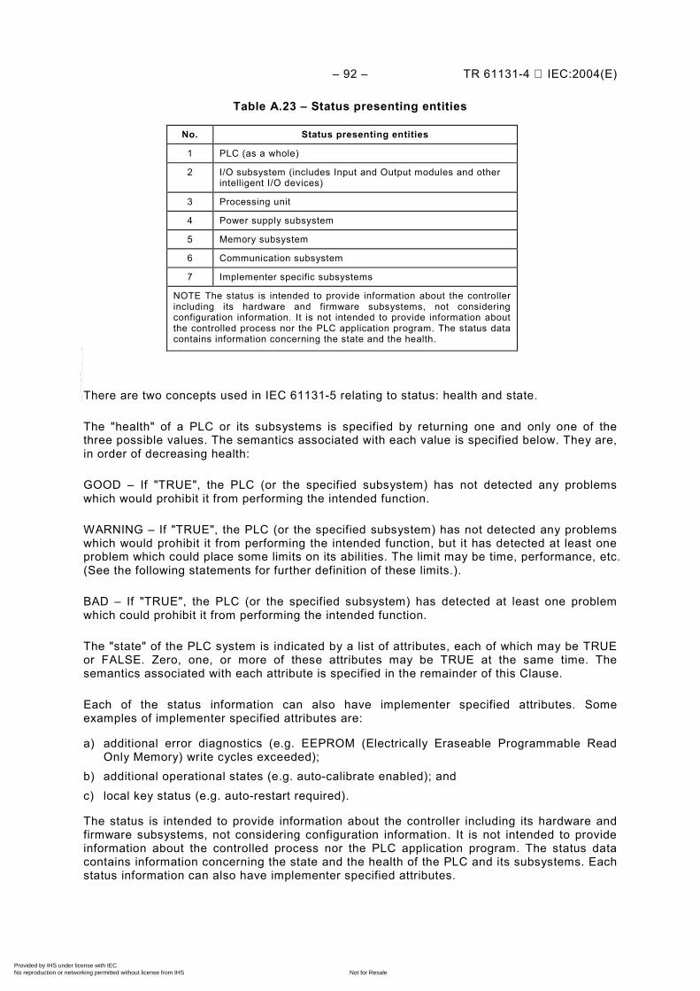
– 92 – TR 61131-4 IEC:2004(E)
Table A.23 – Status presenting entities
No. Status presenting entities
1 PLC (as a whole)
2 I/O subsystem (includes Input and Output modules and other intelligent I/O devices)
3 Processing unit
4 Power supply subsystem
5 Memory subsystem
6 Communication subsystem
7 Implementer specific subsystems
NOTE The status is intended to provide information about the controller including its hardware and firmware subsystems, not considering configuration information. It is not intended to provide information about the controlled process nor the PLC application program. The status data contains information concerning the state and the health.
There are two concepts used in IEC 61131-5 relating to status: health and state.
The "health" of a PLC or its subsystems is specified by returning one and only one of the three possible values. The semantics associated with each value is specified below. They are, in order of decreasing health:
GOOD – If "TRUE", the PLC (or the specified subsystem) has not detected any problems which would prohibit it from performing the intended function.
WARNING – If "TRUE", the PLC (or the specified subsystem) has not detected any problems which would prohibit it from performing the intended function, but it has detected at least one problem which could place some limits on its abilities. The limit may be time, performance, etc. (See the following statements for further definition of these limits.).
BAD – If "TRUE", the PLC (or the specified subsystem) has detected at least one problem which could prohibit it from performing the intended function.
The "state" of the PLC system is indicated by a list of attributes, each of which may be TRUE or FALSE. Zero, one, or more of these attributes may be TRUE at the same time. The semantics associated with each attribute is specified in the remainder of this Clause.
Each of the status information can also have implementer specified attributes. Some examples of implementer specified attributes are:
a) additional error diagnostics (e.g. EEPROM (Electrically Eraseable Programmable Read Only Memory) write cycles exceeded);
b) additional operational states (e.g. auto-calibrate enabled); and c) local key status (e.g. auto-restart required).
The status is intended to provide information about the controller including its hardware and firmware subsystems, not considering configuration information. It is not intended to provide information about the controlled process nor the PLC application program. The status data contains information concerning the state and the health of the PLC and its subsystems. Each status information can also have implementer specified attributes.
Copyright International Electrotechnical Commission Provided by IHS under license with IEC
Not for ResaleNo reproduction or networking permitted without license from IHS
--``````-`-`,,`,,`,`,,`---
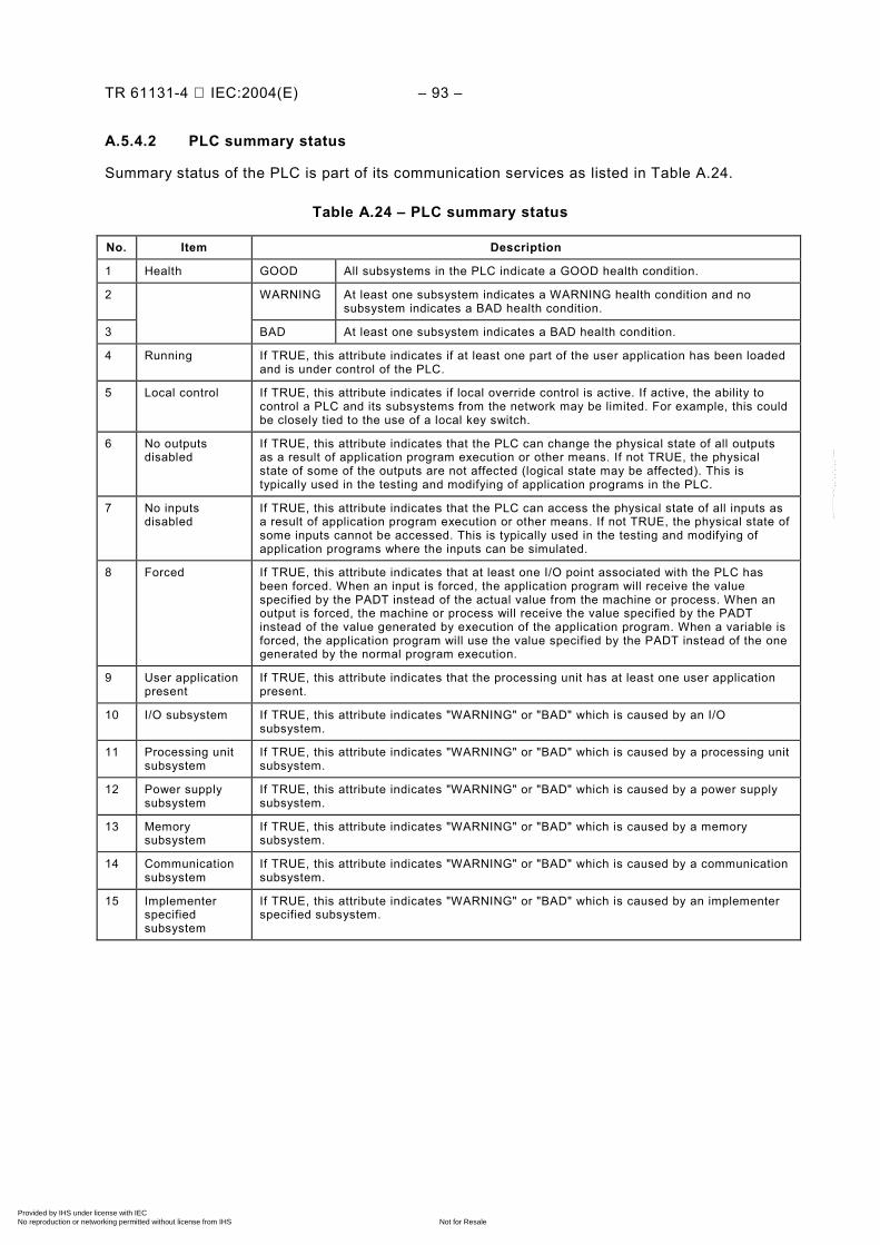
TR 61131-4 IEC:2004(E) – 93 –
A.5.4.2 PLC summary status
Summary status of the PLC is part of its communication services as listed in Table A.24.
Table A.24 – PLC summary status
No. Item Description
1 Health GOOD All subsystems in the PLC indicate a GOOD health condition.
2 WARNING At least one subsystem indicates a WARNING health condition and no subsystem indicates a BAD health condition.
3 BAD At least one subsystem indicates a BAD health condition.
4 Running If TRUE, this attribute indicates if at least one part of the user application has been loaded and is under control of the PLC.
5 Local control If TRUE, this attribute indicates if local override control is active. If active, the ability to control a PLC and its subsystems from the network may be limited. For example, this could be closely tied to the use of a local key switch.
6 No outputs disabled
If TRUE, this attribute indicates that the PLC can change the physical state of all outputs as a result of application program execution or other means. If not TRUE, the physical state of some of the outputs are not affected (logical state may be affected). This is typically used in the testing and modifying of application programs in the PLC.
7 No inputs disabled
If TRUE, this attribute indicates that the PLC can access the physical state of all inputs as a result of application program execution or other means. If not TRUE, the physical state of some inputs cannot be accessed. This is typically used in the testing and modifying of application programs where the inputs can be simulated.
8 Forced If TRUE, this attribute indicates that at least one I/O point associated with the PLC has been forced. When an input is forced, the application program will receive the value specified by the PADT instead of the actual value from the machine or process. When an output is forced, the machine or process will receive the value specified by the PADT instead of the value generated by execution of the application program. When a variable is forced, the application program will use the value specified by the PADT instead of the one generated by the normal program execution.
9 User application present
If TRUE, this attribute indicates that the processing unit has at least one user application present.
10 I/O subsystem If TRUE, this attribute indicates "WARNING" or "BAD" which is caused by an I/O subsystem.
11 Processing unit subsystem
If TRUE, this attribute indicates "WARNING" or "BAD" which is caused by a processing unit subsystem.
12 Power supply subsystem
If TRUE, this attribute indicates "WARNING" or "BAD" which is caused by a power supply subsystem.
13 Memory subsystem
If TRUE, this attribute indicates "WARNING" or "BAD" which is caused by a memory subsystem.
14 Communication subsystem
If TRUE, this attribute indicates "WARNING" or "BAD" which is caused by a communication subsystem.
15 Implementer specified subsystem
If TRUE, this attribute indicates "WARNING" or "BAD" which is caused by an implementer specified subsystem.
Copyright International Electrotechnical Commission Provided by IHS under license with IEC
Not for ResaleNo reproduction or networking permitted without license from IHS
--``````-`-`,,`,,`,`,,`---
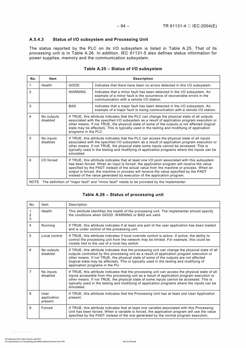
– 94 – TR 61131-4 IEC:2004(E)
A.5.4.3 Status of I/O subsystem and Processing Unit
The status reported by the PLC on its I/O subsystem is listed in Table A.25. That of its processing unit is in Table A.26. In addition, IEC 61131-5 also defines status information for power supplies, memory and the communication subsystem.
Table A.25 – Status of I/O subsystem
No. Item Description
1 Health GOOD Indicates that there have been no errors detected in this I/O subsystem.
2 WARNING Indicates that a minor fault has been detected in the I/O subsystem. An example of a minor fault is the occurrence of recoverable errors in the communication with a remote I/O station.
3 BAD Indicates that a major fault has been detected in the I/O subsystem. An example of a major fault is losing communication with a remote I/O station.
4 No outputs disabled
If TRUE, this attribute indicates that the PLC can change the physical state of all outputs associated with the specified I/O subsystem as a result of application program execution or other means. If not TRUE, the physical state of some of the outputs is not affected (logical state may be affected). This is typically used in the testing and modifying of application programs in the PLC.
5 No inputs disabled
If TRUE, this attribute indicates that the PLC can access the physical state of all inputs associated with the specified I/O subsystem as a result of application program execution or other means. If not TRUE, the physical state some inputs cannot be accessed. This is typically used in the testing and modifying of application programs where the inputs can be simulated.
6 I/O forced If TRUE, this attribute indicates that at least one I/O point associated with this subsystem has been forced. When an input is forced, the application program will receive the value specified by the PADT instead of the actual value from the machine or process. When an output is forced, the machine or process will receive the value specified by the PADT instead of the value generated by execution of the application program.
NOTE The definition of "major fault" and "minor fault" needs to be provided by the implementer.
Table A.26 – Status of processing unit
No. Item Description
1 2 3
Health This attribute identifies the health of the processing unit. The implementer should specify the conditions when GOOD, WARNING or BAD are valid.
4 Running If TRUE, this attribute indicates if at least one part of the user application has been loaded and is under control of the processing unit.
5 Local control If TRUE, this attribute indicates if local override control is active. If active, the ability to control the processing unit from the network may be limited. For example, this could be closely tied to the use of a local key switch.
6 No outputs disabled
If TRUE, this attribute indicates that the processing unit can change the physical state of all outputs controlled by this processing unit as a result of application program execution or other means. If not TRUE, the physical state of some of the outputs are not affected (logical state may be affected). This is typically used in the testing and modifying of application programs in the PU.
7 No inputs disabled
If TRUE, this attribute indicates that the processing unit can access the physical state of all inputs accessible from this processing unit as a result of application program execution or other means. If not TRUE, the physical state of some inputs cannot be accessed. This is typically used in the testing and modifying of application programs where the inputs can be simulated.
8 User application present
If TRUE, this attribute indicates that the Processing Unit has at least one User Application present.
9 Forced If TRUE, this attribute indicates that at least one variable associated with this Processing Unit has been forced. When a variable is forced, the application program will use the value specified by the PADT instead of the one generated by the normal program execution.
Copyright International Electrotechnical Commission Provided by IHS under license with IEC
Not for ResaleNo reproduction or networking permitted without license from IHS
--``````-`-`,,`,,`,`,,`---
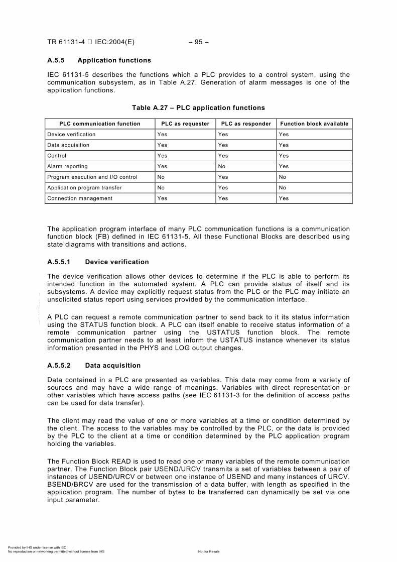
TR 61131-4 IEC:2004(E) – 95 –
A.5.5 Application functions
IEC 61131-5 describes the functions which a PLC provides to a control system, using the communication subsystem, as in Table A.27. Generation of alarm messages is one of the application functions.
Table A.27 – PLC application functions
PLC communication function PLC as requester PLC as responder Function block available
Device verification Yes Yes Yes
Data acquisition Yes Yes Yes
Control Yes Yes Yes
Alarm reporting Yes No Yes
Program execution and I/O control No Yes No
Application program transfer No Yes No
Connection management Yes Yes Yes
The application program interface of many PLC communication functions is a communication function block (FB) defined in IEC 61131-5. All these Functional Blocks are described using state diagrams with transitions and actions.
A.5.5.1 Device verification
The device verification allows other devices to determine if the PLC is able to perform its intended function in the automated system. A PLC can provide status of itself and its subsystems. A device may explicitly request status from the PLC or the PLC may initiate an unsolicited status report using services provided by the communication interface.
A PLC can request a remote communication partner to send back to it its status information using the STATUS function block. A PLC can itself enable to receive status information of a remote communication partner using the USTATUS function block. The remote communication partner needs to at least inform the USTATUS instance whenever its status information presented in the PHYS and LOG output changes.
A.5.5.2 Data acquisition
Data contained in a PLC are presented as variables. This data may come from a variety of sources and may have a wide range of meanings. Variables with direct representation or other variables which have access paths (see IEC 61131-3 for the definition of access paths can be used for data transfer).
The client may read the value of one or more variables at a time or condition determined by the client. The access to the variables may be controlled by the PLC, or the data is provided by the PLC to the client at a time or condition determined by the PLC application program holding the variables.
The Function Block READ is used to read one or many variables of the remote communication partner. The Function Block pair USEND/URCV transmits a set of variables between a pair of instances of USEND/URCV or between one instance of USEND and many instances of URCV. BSEND/BRCV are used for the transmission of a data buffer, with length as specified in the application program. The number of bytes to be transferred can dynamically be set via one input parameter.
Copyright International Electrotechnical Commission Provided by IHS under license with IEC
Not for ResaleNo reproduction or networking permitted without license from IHS
--``````-`-`,,`,,`,`,,`---
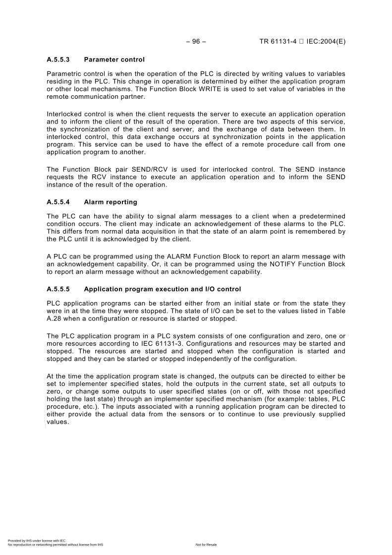
– 96 – TR 61131-4 IEC:2004(E)
A.5.5.3 Parameter control
Parametric control is when the operation of the PLC is directed by writing values to variables residing in the PLC. This change in operation is determined by either the application program or other local mechanisms. The Function Block WRITE is used to set value of variables in the remote communication partner.
Interlocked control is when the client requests the server to execute an application operation and to inform the client of the result of the operation. There are two aspects of this service, the synchronization of the client and server, and the exchange of data between them. In interlocked control, this data exchange occurs at synchronization points in the application program. This service can be used to have the effect of a remote procedure call from one application program to another.
The Function Block pair SEND/RCV is used for interlocked control. The SEND instance requests the RCV instance to execute an application operation and to inform the SEND instance of the result of the operation.
A.5.5.4 Alarm reporting
The PLC can have the ability to signal alarm messages to a client when a predetermined condition occurs. The client may indicate an acknowledgement of these alarms to the PLC. This differs from normal data acquisition in that the state of an alarm point is remembered by the PLC until it is acknowledged by the client.
A PLC can be programmed using the ALARM Function Block to report an alarm message with an acknowledgement capability. Or, it can be programmed using the NOTIFY Function Block to report an alarm message without an acknowledgement capability.
A.5.5.5 Application program execution and I/O control
PLC application programs can be started either from an initial state or from the state they were in at the time they were stopped. The state of I/O can be set to the values listed in Table A.28 when a configuration or resource is started or stopped.
The PLC application program in a PLC system consists of one configuration and zero, one or more resources according to IEC 61131-3. Configurations and resources may be started and stopped. The resources are started and stopped when the configuration is started and stopped and they can be started or stopped independently of the configuration.
At the time the application program state is changed, the outputs can be directed to either be set to implementer specified states, hold the outputs in the current state, set all outputs to zero, or change some outputs to user specified states (on or off, with those not specified holding the last state) through an implementer specified mechanism (for example: tables, PLC procedure, etc.). The inputs associated with a running application program can be directed to either provide the actual data from the sensors or to continue to use previously supplied values.
Copyright International Electrotechnical Commission Provided by IHS under license with IEC
Not for ResaleNo reproduction or networking permitted without license from IHS
--``````-`-`,,`,,`,`,,`---
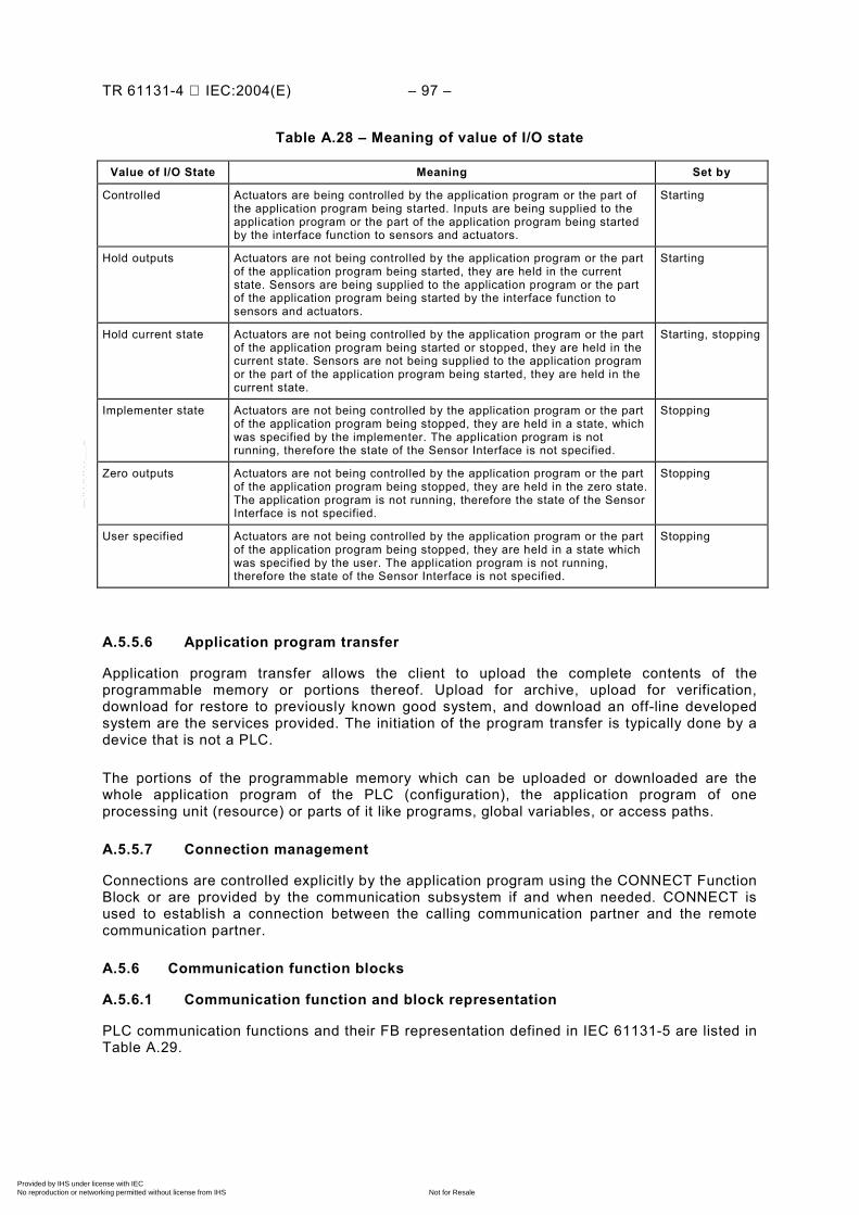
TR 61131-4 IEC:2004(E) – 97 –
Table A.28 – Meaning of value of I/O state
Value of I/O State Meaning Set by
Controlled Actuators are being controlled by the application program or the part of the application program being started. Inputs are being supplied to the application program or the part of the application program being started by the interface function to sensors and actuators.
Starting
Hold outputs Actuators are not being controlled by the application program or the part of the application program being started, they are held in the current state. Sensors are being supplied to the application program or the part of the application program being started by the interface function to sensors and actuators.
Starting
Hold current state Actuators are not being controlled by the application program or the part of the application program being started or stopped, they are held in the current state. Sensors are not being supplied to the application program or the part of the application program being started, they are held in the current state.
Starting, stopping
Implementer state Actuators are not being controlled by the application program or the part of the application program being stopped, they are held in a state, which was specified by the implementer. The application program is not running, therefore the state of the Sensor Interface is not specified.
Stopping
Zero outputs Actuators are not being controlled by the application program or the part of the application program being stopped, they are held in the zero state. The application program is not running, therefore the state of the Sensor Interface is not specified.
Stopping
User specified Actuators are not being controlled by the application program or the part of the application program being stopped, they are held in a state which was specified by the user. The application program is not running, therefore the state of the Sensor Interface is not specified.
Stopping
A.5.5.6 Application program transfer
Application program transfer allows the client to upload the complete contents of the programmable memory or portions thereof. Upload for archive, upload for verification, download for restore to previously known good system, and download an off-line developed system are the services provided. The initiation of the program transfer is typically done by a device that is not a PLC.
The portions of the programmable memory which can be uploaded or downloaded are the whole application program of the PLC (configuration), the application program of one processing unit (resource) or parts of it like programs, global variables, or access paths.
A.5.5.7 Connection management
Connections are controlled explicitly by the application program using the CONNECT Function Block or are provided by the communication subsystem if and when needed. CONNECT is used to establish a connection between the calling communication partner and the remote communication partner.
A.5.6 Communication function blocks
A.5.6.1 Communication function and block representation
PLC communication functions and their FB representation defined in IEC 61131-5 are listed in Table A.29.
Copyright International Electrotechnical Commission Provided by IHS under license with IEC
Not for ResaleNo reproduction or networking permitted without license from IHS
--``````-`-`,,`,,`,`,,`---
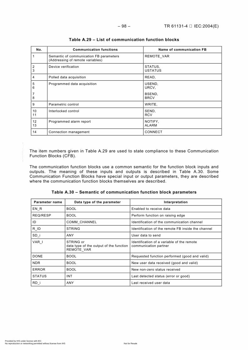
– 98 – TR 61131-4 IEC:2004(E)
Table A.29 – List of communication function blocks
No. Communication functions Name of communication FB
1 Semantic of communication FB parameters (Addressing of remote variables)
REMOTE_VAR
2 3
Device verification STATUS, USTATUS
4 Polled data acquisition READ,
5 6
7 8
Programmed data acquisition USEND, URCV,
BSEND, BRCV
9 Parametric control WRITE,
10 11
Interlocked control SEND, RCV
12 13
Programmed alarm report NOTIFY, ALARM
14 Connection management CONNECT
The item numbers given in Table A.29 are used to state compliance to these Communication Function Blocks (CFB).
The communication function blocks use a common semantic for the function block inputs and outputs. The meaning of these inputs and outputs is described in Table A.30. Some Communication Function Blocks have special input or output parameters, they are described where the communication function blocks themselves are described.
Table A.30 – Semantic of communication function block parameters
Parameter name Data type of the parameter Interpretation
EN_R BOOL Enabled to receive data
REQ/RESP BOOL Perform function on raising edge
ID COMM_CHANNEL Identification of the communication channel
R_ID STRING Identification of the remote FB inside the channel
SD_i ANY User data to send
VAR_I STRING or data type of the output of the function REMOTE_VAR
Identification of a variable of the remote communication partner
DONE BOOL Requested function performed (good and valid)
NDR BOOL New user data received (good and valid)
ERROR BOOL New non-zero status received
STATUS INT Last detected status (error or good)
RD_i ANY Last received user data
Copyright International Electrotechnical Commission Provided by IHS under license with IEC
Not for ResaleNo reproduction or networking permitted without license from IHS
--``````-`-`,,`,,`,`,,`---
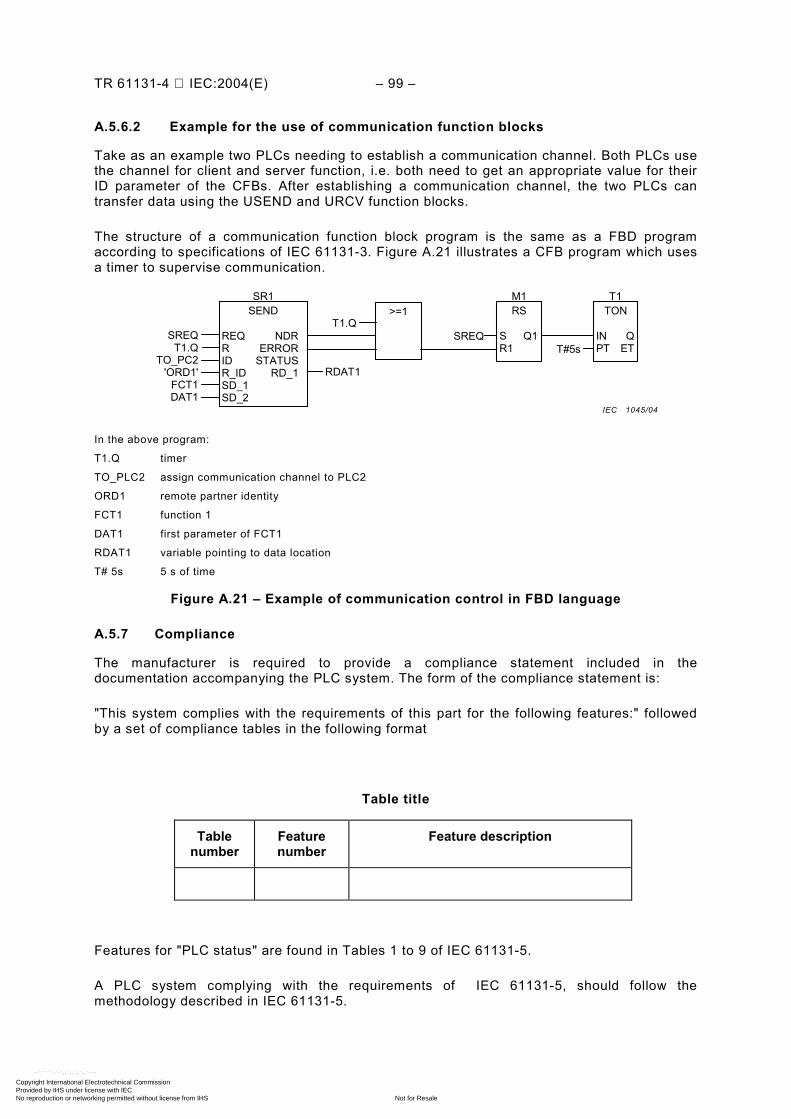
TR 61131-4 IEC:2004(E) – 99 –
A.5.6.2 Example for the use of communication function blocks
Take as an example two PLCs needing to establish a communication channel. Both PLCs use the channel for client and server function, i.e. both need to get an appropriate value for their ID parameter of the CFBs. After establishing a communication channel, the two PLCs can transfer data using the USEND and URCV function blocks.
The structure of a communication function block program is the same as a FBD program according to specifications of IEC 61131-3. Figure A.21 illustrates a CFB program which uses a timer to supervise communication.
TON
IN QPT ET
RS
S Q1R1
>=1SEND
REQ NDRR ERRORID STATUSR_ID RD_1SD_1SD_2
SREQT1.Q
TO_PC2'ORD1'
FCT1DAT1
RDAT1
SR1 T1M1
T1.Q
T#5sSREQ
In the above program:
T1.Q timer
TO_PLC2 assign communication channel to PLC2
ORD1 remote partner identity
FCT1 function 1
DAT1 first parameter of FCT1
RDAT1 variable pointing to data location
T# 5s 5 s of time
Figure A.21 – Example of communication control in FBD language
A.5.7 Compliance
The manufacturer is required to provide a compliance statement included in the documentation accompanying the PLC system. The form of the compliance statement is:
"This system complies with the requirements of this part for the following features:" followed by a set of compliance tables in the following format
Table title
Table number
Feature number
Feature description
Features for "PLC status" are found in Tables 1 to 9 of IEC 61131-5.
A PLC system complying with the requirements of IEC 61131-5, should follow the methodology described in IEC 61131-5.
IEC 1045/04
Copyright International Electrotechnical Commission Provided by IHS under license with IEC
Not for ResaleNo reproduction or networking permitted without license from IHS
--``````-`-`,,`,,`,`,,`---
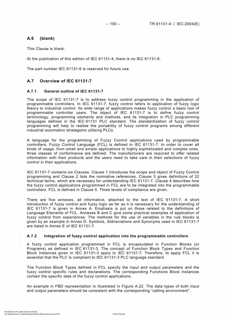
– 100 – TR 61131-4 IEC:2004(E)
A.6 (blank)
This Clause is blank.
At the publication of this edition of IEC 61131-4, there is no IEC 61131-6.
The part number IEC 61131-6 is reserved for future use.
A.7 Overview of IEC 61131-7
A.7.1 General outline of IEC 61131-7
The scope of IEC 61131-7 is to address fuzzy control programming in the application of programmable controllers. In IEC 61131-7, fuzzy control refers to application of fuzzy logic theory to industrial control. Its wide range of applications makes fuzzy control a basic tool of programmable controller users. The object of IEC 61131-7 is to define fuzzy control terminology, programming elements and methods, and its integration in PLC programming languages defined in the IEC 61131 PLC standard. The standardization of fuzzy control programming will help to realise the portability of fuzzy control programs among different industrial automation stratagems utilising PLCs.
A language for the programming of Fuzzy Control applications used by programmable controllers, Fuzzy Control Language (FCL) is defined in IEC 61131-7. In order to cover all kinds of usage, from small and simple applications to highly sophisticated and complex ones, three classes of conformance are defined. The manufacturers are required to offer related information with their products and the users need to take care in their selections of fuzzy control in their applications.
IEC 61131-7 contains six Clauses. Clause 1 introduces the scope and object of Fuzzy Control programming and Clause 2 lists the normative references. Clause 3 gives definitions of 22 technical terms, which are necessary for understanding IEC 61131-7. Clause 4 describes how the fuzzy control applications programmed in FCL are to be integrated into the programmable controllers. FCL is defined in Clause 5. Three levels of compliance are given.
There are five annexes, all informative, attached to the text of IEC 61131-7. A short introduction of fuzzy control and fuzzy logic as far as it is necessary for the understanding of IEC 61131-7 is given in Annex A. Emphasis is put on those related to the definitions of Language Elements of FCL. Annexes B and C give some practical examples of application of fuzzy control from experiences. The methods for the use of variables in the rule blocks is given by an example in Annex D. Symbols, Abbreviations and Synonyms used in IEC 61131-7 are listed in Annex E of IEC 61131-7.
A.7.2 Integration of fuzzy control application into the programmable controllers
A fuzzy control application programmed in FCL is encapsulated in Function Blocks (or Programs) as defined in IEC 61131-3. The concept of Function Block Types and Function Block Instances given in IEC 61131-3 apply to IEC 61131-7. Therefore, to apply FCL it is essential that the PLC is compliant to IEC 61131-3 PLC language standard.
The Function Block Types defined in FCL specify the input and output parameters and the fuzzy control specific rules and declarations. The corresponding Functions Block Instances contain the specific data of the fuzzy control applications.
An example in FBD representation is illustrated in Figure A.22. The data types of both input and output parameters should be consistent with the corresponding “calling environment”.
Copyright International Electrotechnical Commission Provided by IHS under license with IEC
Not for ResaleNo reproduction or networking permitted without license from IHS
--``````-`-`,,`,,`,`,,`---
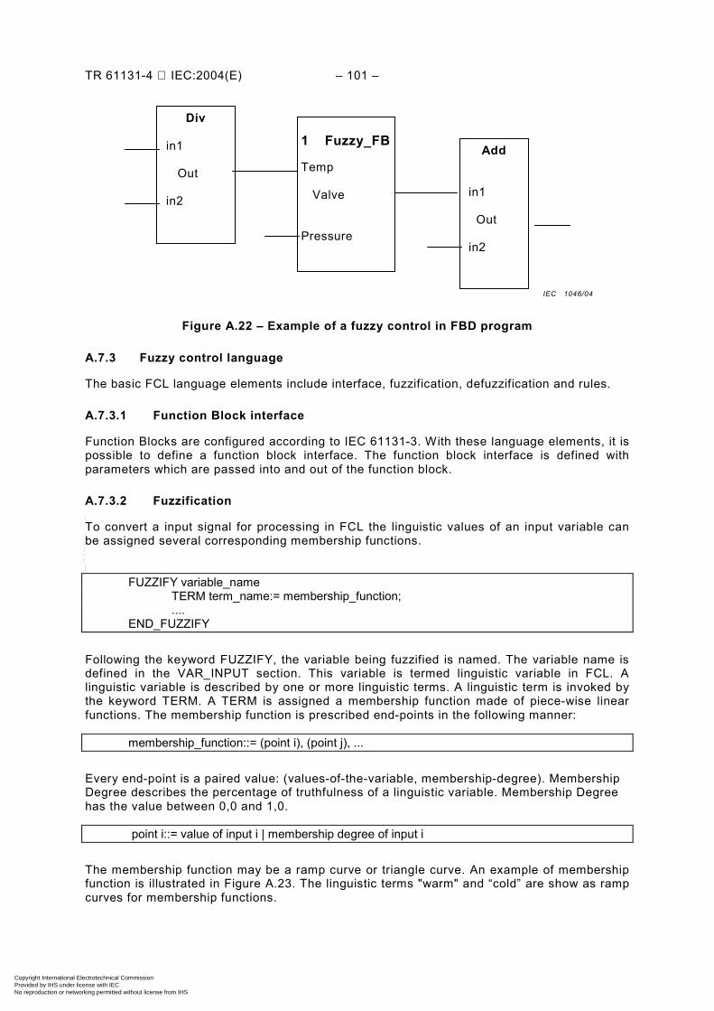
TR 61131-4 IEC:2004(E) – 101 –
Figure A.22 – Example of a fuzzy control in FBD program
A.7.3 Fuzzy control language
The basic FCL language elements include interface, fuzzification, defuzzification and rules.
A.7.3.1 Function Block interface
Function Blocks are configured according to IEC 61131-3. With these language elements, it is possible to define a function block interface. The function block interface is defined with parameters which are passed into and out of the function block.
A.7.3.2 Fuzzification
To convert a input signal for processing in FCL the linguistic values of an input variable can be assigned several corresponding membership functions.
FUZZIFY variable_name TERM term_name:= membership_function; .... END_FUZZIFY
Following the keyword FUZZIFY, the variable being fuzzified is named. The variable name is defined in the VAR_INPUT section. This variable is termed linguistic variable in FCL. A linguistic variable is described by one or more linguistic terms. A linguistic term is invoked by the keyword TERM. A TERM is assigned a membership function made of piece-wise linear functions. The membership function is prescribed end-points in the following manner:
membership_function::= (point i), (point j), ...
Every end-point is a paired value: (values-of-the-variable, membership-degree). Membership Degree describes the percentage of truthfulness of a linguistic variable. Membership Degree has the value between 0,0 and 1,0.
point i::= value of input i | membership degree of input i The membership function may be a ramp curve or triangle curve. An example of membership function is illustrated in Figure A.23. The linguistic terms "warm" and “cold” are show as ramp curves for membership functions.
Div in1 Out
in2
1 Fuzzy_FB
Temp Valve Pressure
Add in1 Out in2
IEC 1046/04
Copyright International Electrotechnical Commission Provided by IHS under license with IEC
Not for ResaleNo reproduction or networking permitted without license from IHS
--``````-`-`,,`,,`,`,,`---
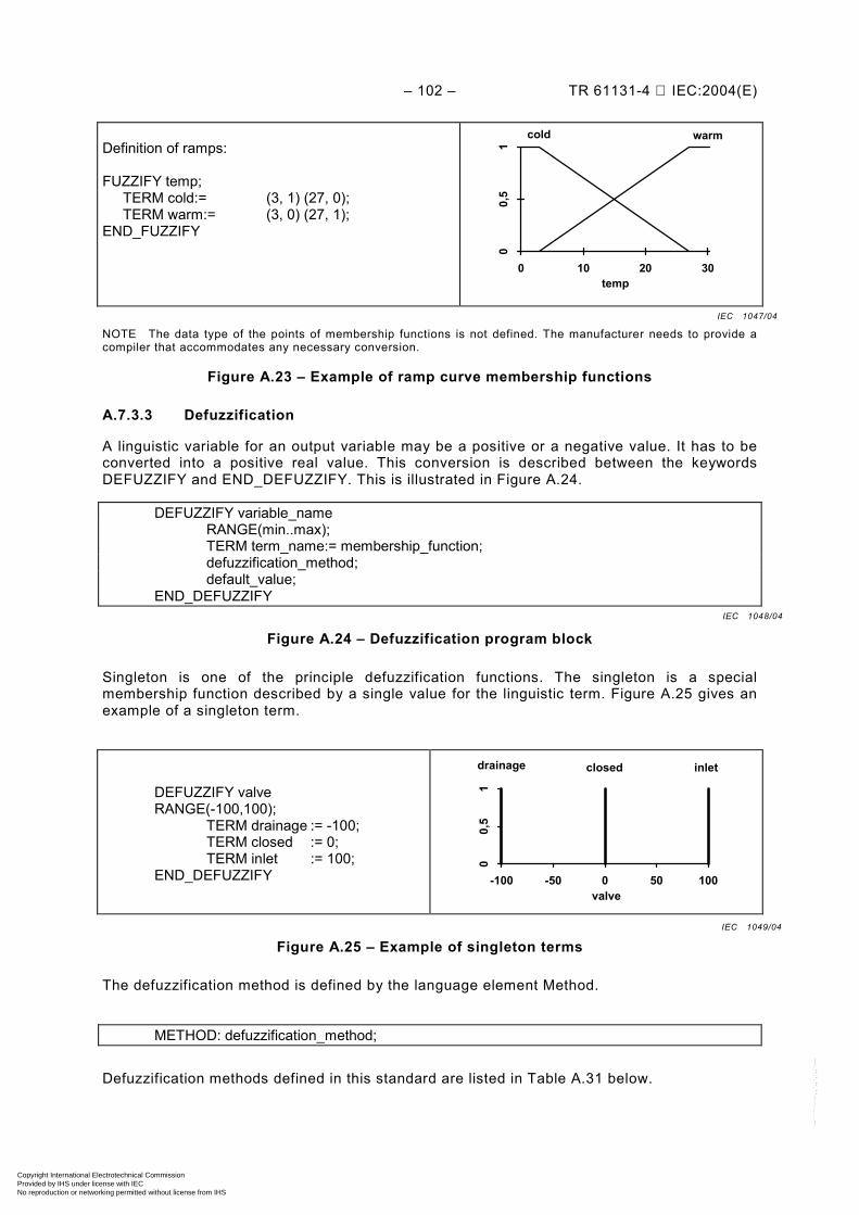
– 102 – TR 61131-4 IEC:2004(E)
Definition of ramps: FUZZIFY temp; TERM cold:= (3, 1) (27, 0); TERM warm:= (3, 0) (27, 1); END_FUZZIFY
00,
51
0 10 20 30
cold warm
temp
NOTE The data type of the points of membership functions is not defined. The manufacturer needs to provide a compiler that accommodates any necessary conversion.
Figure A.23 – Example of ramp curve membership functions
A.7.3.3 Defuzzification
A linguistic variable for an output variable may be a positive or a negative value. It has to be converted into a positive real value. This conversion is described between the keywords DEFUZZIFY and END_DEFUZZIFY. This is illustrated in Figure A.24.
DEFUZZIFY variable_name RANGE(min..max); TERM term_name:= membership_function; defuzzification_method; default_value; END_DEFUZZIFY
Figure A.24 – Defuzzification program block
Singleton is one of the principle defuzzification functions. The singleton is a special membership function described by a single value for the linguistic term. Figure A.25 gives an example of a singleton term.
DEFUZZIFY valve RANGE(-100,100); TERM drainage := -100; TERM closed := 0; TERM inlet := 100; END_DEFUZZIFY
00,
51
-100 -50 0 50 100
drainage closed inlet
valve
Figure A.25 – Example of singleton terms
The defuzzification method is defined by the language element Method.
METHOD: defuzzification_method;
Defuzzification methods defined in this standard are listed in Table A.31 below.
IEC 1047/04
IEC 1048/04
IEC 1049/04
Copyright International Electrotechnical Commission Provided by IHS under license with IEC
Not for ResaleNo reproduction or networking permitted without license from IHS
--``````-`-`,,`,,`,`,,`---
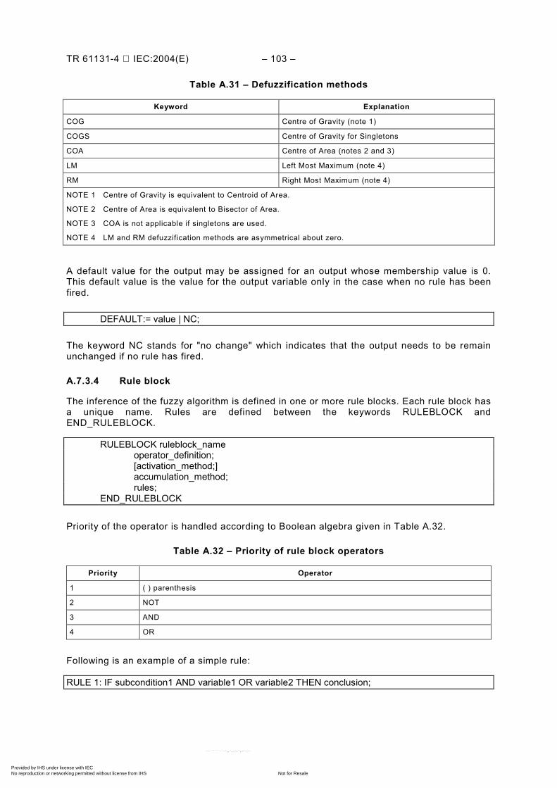
TR 61131-4 IEC:2004(E) – 103 –
Table A.31 – Defuzzification methods
Keyword Explanation
COG Centre of Gravity (note 1)
COGS Centre of Gravity for Singletons
COA Centre of Area (notes 2 and 3)
LM Left Most Maximum (note 4)
RM Right Most Maximum (note 4)
NOTE 1 Centre of Gravity is equivalent to Centroid of Area.
NOTE 2 Centre of Area is equivalent to Bisector of Area.
NOTE 3 COA is not applicable if singletons are used.
NOTE 4 LM and RM defuzzification methods are asymmetrical about zero.
A default value for the output may be assigned for an output whose membership value is 0. This default value is the value for the output variable only in the case when no rule has been fired.
DEFAULT:= value | NC;
The keyword NC stands for "no change" which indicates that the output needs to be remain unchanged if no rule has fired.
A.7.3.4 Rule block
The inference of the fuzzy algorithm is defined in one or more rule blocks. Each rule block has a unique name. Rules are defined between the keywords RULEBLOCK and END_RULEBLOCK.
RULEBLOCK ruleblock_name operator_definition; [activation_method;] accumulation_method; rules; END_RULEBLOCK
Priority of the operator is handled according to Boolean algebra given in Table A.32.
Table A.32 – Priority of rule block operators
Priority Operator
1 ( ) parenthesis
2 NOT
3 AND
4 OR
Following is an example of a simple rule:
RULE 1: IF subcondition1 AND variable1 OR variable2 THEN conclusion;
Copyright International Electrotechnical Commission Provided by IHS under license with IEC
Not for ResaleNo reproduction or networking permitted without license from IHS
--``````-`-`,,`,,`,`,,`---
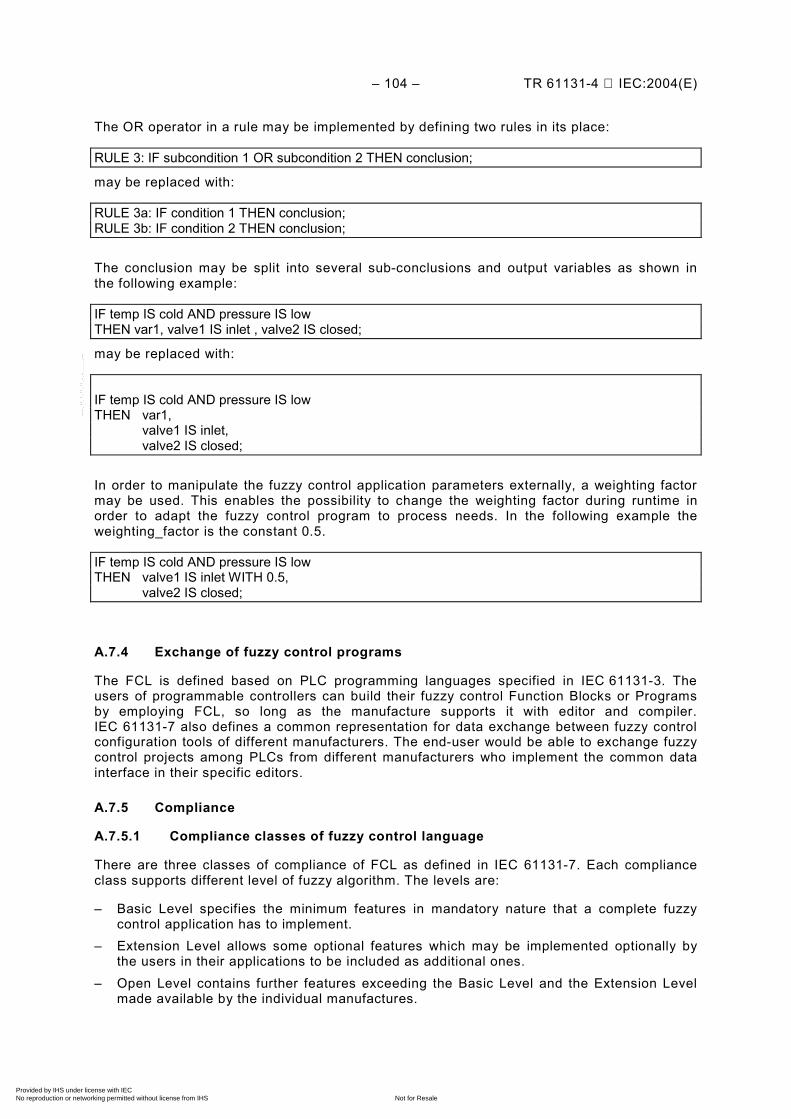
– 104 – TR 61131-4 IEC:2004(E)
The OR operator in a rule may be implemented by defining two rules in its place:
RULE 3: IF subcondition 1 OR subcondition 2 THEN conclusion;
may be replaced with:
RULE 3a: IF condition 1 THEN conclusion; RULE 3b: IF condition 2 THEN conclusion; The conclusion may be split into several sub-conclusions and output variables as shown in the following example:
IF temp IS cold AND pressure IS low THEN var1, valve1 IS inlet , valve2 IS closed;
may be replaced with:
IF temp IS cold AND pressure IS low THEN var1, valve1 IS inlet, valve2 IS closed; In order to manipulate the fuzzy control application parameters externally, a weighting factor may be used. This enables the possibility to change the weighting factor during runtime in order to adapt the fuzzy control program to process needs. In the following example the weighting_factor is the constant 0.5.
IF temp IS cold AND pressure IS low THEN valve1 IS inlet WITH 0.5,
valve2 IS closed;
A.7.4 Exchange of fuzzy control programs
The FCL is defined based on PLC programming languages specified in IEC 61131-3. The users of programmable controllers can build their fuzzy control Function Blocks or Programs by employing FCL, so long as the manufacture supports it with editor and compiler. IEC 61131-7 also defines a common representation for data exchange between fuzzy control configuration tools of different manufacturers. The end-user would be able to exchange fuzzy control projects among PLCs from different manufacturers who implement the common data interface in their specific editors.
A.7.5 Compliance
A.7.5.1 Compliance classes of fuzzy control language
There are three classes of compliance of FCL as defined in IEC 61131-7. Each compliance class supports different level of fuzzy algorithm. The levels are:
– Basic Level specifies the minimum features in mandatory nature that a complete fuzzy control application has to implement.
– Extension Level allows some optional features which may be implemented optionally by the users in their applications to be included as additional ones.
– Open Level contains further features exceeding the Basic Level and the Extension Level made available by the individual manufactures.
Copyright International Electrotechnical Commission Provided by IHS under license with IEC
Not for ResaleNo reproduction or networking permitted without license from IHS
--``````-`-`,,`,,`,`,,`---
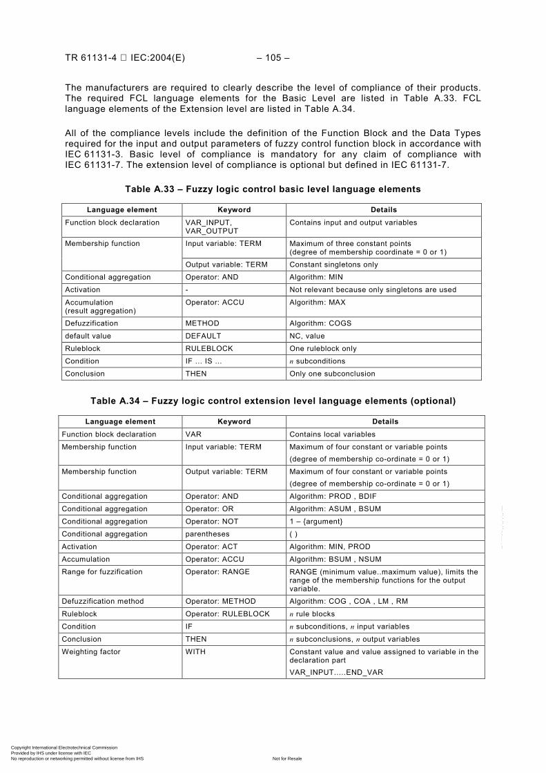
TR 61131-4 IEC:2004(E) – 105 –
The manufacturers are required to clearly describe the level of compliance of their products. The required FCL language elements for the Basic Level are listed in Table A.33. FCL language elements of the Extension level are listed in Table A.34.
All of the compliance levels include the definition of the Function Block and the Data Types required for the input and output parameters of fuzzy control function block in accordance with IEC 61131-3. Basic level of compliance is mandatory for any claim of compliance with IEC 61131-7. The extension level of compliance is optional but defined in IEC 61131-7.
Table A.33 – Fuzzy logic control basic level language elements
Language element Keyword Details Function block declaration VAR_INPUT,
VAR_OUTPUT Contains input and output variables
Input variable: TERM Maximum of three constant points (degree of membership coordinate = 0 or 1)
Membership function
Output variable: TERM Constant singletons only
Conditional aggregation Operator: AND Algorithm: MIN
Activation - Not relevant because only singletons are used
Accumulation (result aggregation)
Operator: ACCU Algorithm: MAX
Defuzzification METHOD Algorithm: COGS
default value DEFAULT NC, value
Ruleblock RULEBLOCK One ruleblock only
Condition IF ... IS ... n subconditions
Conclusion THEN Only one subconclusion
Table A.34 – Fuzzy logic control extension level language elements (optional)
Language element Keyword Details Function block declaration VAR Contains local variables
Membership function Input variable: TERM Maximum of four constant or variable points (degree of membership co-ordinate = 0 or 1)
Membership function Output variable: TERM Maximum of four constant or variable points (degree of membership co-ordinate = 0 or 1)
Conditional aggregation Operator: AND Algorithm: PROD , BDIF
Conditional aggregation Operator: OR Algorithm: ASUM , BSUM
Conditional aggregation Operator: NOT 1 – argument
Conditional aggregation parentheses ( )
Activation Operator: ACT Algorithm: MIN, PROD
Accumulation Operator: ACCU Algorithm: BSUM , NSUM
Range for fuzzification Operator: RANGE RANGE (minimum value..maximum value), limits the range of the membership functions for the output variable.
Defuzzification method Operator: METHOD Algorithm: COG , COA , LM , RM
Ruleblock Operator: RULEBLOCK n rule blocks
Condition IF n subconditions, n input variables
Conclusion THEN n subconclusions, n output variables
Weighting factor WITH Constant value and value assigned to variable in the declaration part VAR_INPUT.....END_VAR
Copyright International Electrotechnical Commission Provided by IHS under license with IEC
Not for ResaleNo reproduction or networking permitted without license from IHS
--``````-`-`,,`,,`,`,,`---
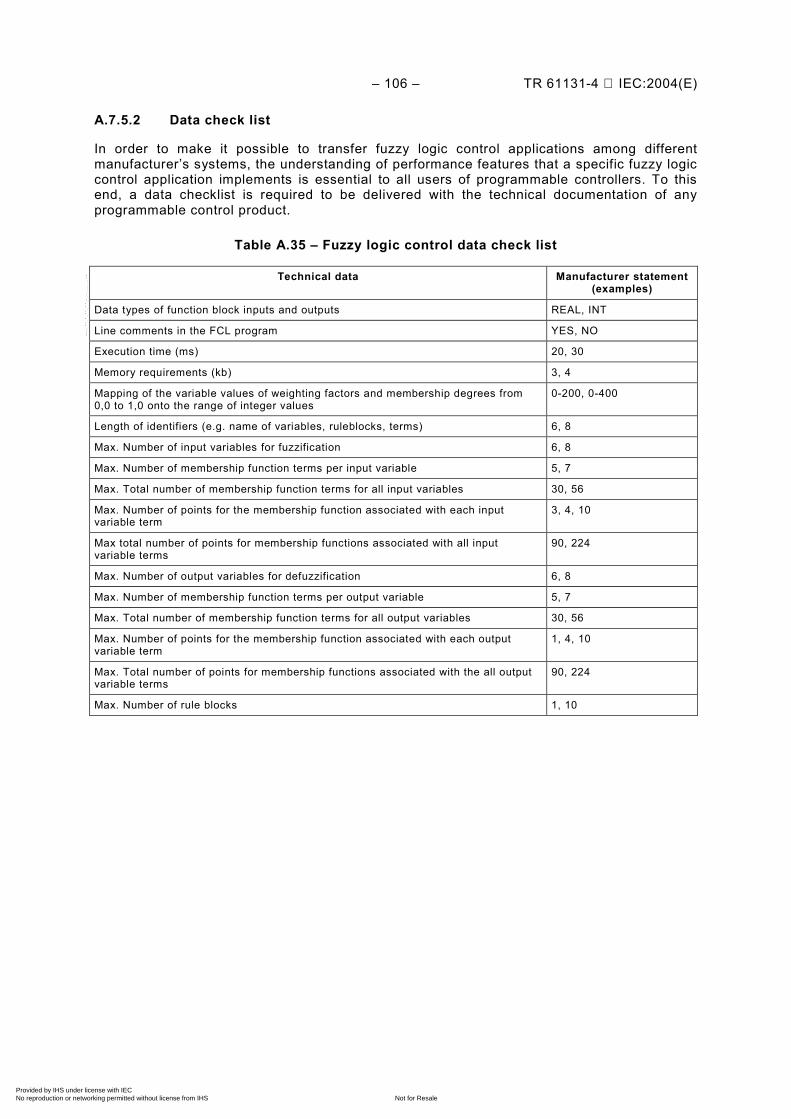
– 106 – TR 61131-4 IEC:2004(E)
A.7.5.2 Data check list
In order to make it possible to transfer fuzzy logic control applications among different manufacturer’s systems, the understanding of performance features that a specific fuzzy logic control application implements is essential to all users of programmable controllers. To this end, a data checklist is required to be delivered with the technical documentation of any programmable control product.
Table A.35 – Fuzzy logic control data check list
Technical data Manufacturer statement(examples)
Data types of function block inputs and outputs REAL, INT
Line comments in the FCL program YES, NO
Execution time (ms) 20, 30
Memory requirements (kb) 3, 4
Mapping of the variable values of weighting factors and membership degrees from 0,0 to 1,0 onto the range of integer values
0-200, 0-400
Length of identifiers (e.g. name of variables, ruleblocks, terms) 6, 8
Max. Number of input variables for fuzzification 6, 8
Max. Number of membership function terms per input variable 5, 7
Max. Total number of membership function terms for all input variables 30, 56
Max. Number of points for the membership function associated with each input variable term
3, 4, 10
Max total number of points for membership functions associated with all input variable terms
90, 224
Max. Number of output variables for defuzzification 6, 8
Max. Number of membership function terms per output variable 5, 7
Max. Total number of membership function terms for all output variables 30, 56
Max. Number of points for the membership function associated with each output variable term
1, 4, 10
Max. Total number of points for membership functions associated with the all output variable terms
90, 224
Max. Number of rule blocks 1, 10
Copyright International Electrotechnical Commission Provided by IHS under license with IEC
Not for ResaleNo reproduction or networking permitted without license from IHS
--``````-`-`,,`,,`,`,,`---
TR 61131-4 IEC:2004(E) – 107 –
A.8 (blank)
This Clause is blank.
IEC 61131-8 is itself a guidelines Technical Report.
It is not reviewed in this Technical Report.
Copyright International Electrotechnical Commission Provided by IHS under license with IEC
Not for ResaleNo reproduction or networking permitted without license from IHS
--``````-`-`,,`,,`,`,,`---

– 108 – TR 61131-4 IEC:2004(E)
Annex B (informative)
Conformity to IEC 61131 and product certification
B.1 General
This annex gives some background information on conformity to standards for contracts or, to fulfil legal requirements. Particular emphasis is paid to the situation in the European Community and IEC 61131-2 for hardware issues. The terminologies from ISO/IEC Guide 2, the European Low Voltage Directive and the EMC Directive are used as closely as possible throughout this annex.
B.2 Conformity to standards
With particular reference to European practice, if a vendor and a buyer agree upon a contract, the application of standards pertaining to the contract is voluntary in most countries. For instance, in the European Union (EU), if the buyer does not belong to one of the sectors of public companies outlined by the public procurement directives, then the application of standards is voluntary.
A vendor-user agreement which contains a reference to a standard would come into force with the vendor’s statement ”Our PLC Model xyz complies with IEC 61131-X” (in the case involving IEC standards). In such an inclusive statement, the vendor has to fulfil all requirements of IEC 61131-X without any exception. If the vendor fails to do so, then he would not be fulfilling the contract. If this were the case, and the aforementioned statement were part of a marketing brochure, the public might be misled and therefore, such situations should be avoided because they may have negative legal ramifications.
ISO/IEC Directives Part 2 (downloadable from the IEC homepage http://www.iec.ch) gives clear instructions as to which provisions of a standard are mandatory, which ones are recommendations, and which are descriptive only. Mandatory provisions are for example those expressed with ”shall” or ”has to”. The foreword of every IEC standard now references the directives explicitly to further elucidate the meaning of these mandatory verbal forms.
Parts of IEC 61131 also include provisions on how to declare conformity to the standards. For instance, for IEC 61131-2, when compliance is indicated without qualification, then compliance with all clauses, including all tests and verifications required in IEC 61131-2, must be verified. When compliance with some portion of IEC 61131-2 is indicated, it is only necessary to verify compliance with those clauses against which the compliance claim is made. For partial compliance IEC 61131-3, IEC 61131-5 and IEC 61131-7 require the vendor to draw up tables delineating the features to which he complies. It should be noted here that a set of basic features is specified for minimal conformance in IEC 61131-3, IEC 61131-5 and IEC 61131-7.
IEC 61131-1 defines terminology and models. IEC 61131-4 provides explanatory background information, and thus declaration of conformity to these publications is not applicable.
Copyright International Electrotechnical Commission Provided by IHS under license with IEC
Not for ResaleNo reproduction or networking permitted without license from IHS
--``````-`-`,,`,,`,`,,`---

TR 61131-4 IEC:2004(E) – 109 –
B.3 Declaration of conformity and certification
According to ISO/IEC Guide 2, 12.1, conformity is the fulfilment by a product, process or service of specified requirements. In the case of the product PLC, conformity may be declared to an international standard, as in the IEC 61131 series, a national standard or a consortia standard. An example of the latter is the specification of PLCopen, a consortium which is committed to the application of IEC 61131-3.
Depending on the person who, or institution which, is making the declaration of conformity, there are three types of declarations of conformity:
– Supplier’s declaration. The supplier, himself, declares the conformity of his product to a standard, thereby taking full responsibility for the declaration. The supplier may issue a product brochure with the statement ”according to IEC 61131-X”. In many cases when the supplier is identical to the manufacturer, then the supplier’s declaration is also the manufacturer’s declaration.
– Buyer’s declaration. For example, some industrial users keep catalogues of devices which conform to their specifications and may be installed in their factories. The entry of a device in such a catalogue can be viewed as the buyer’s declaration of conformity to his requirements.
– Third party declaration. If neither the supplier nor the buyer verifies conformity to a certain standard, but a third party does it for them, this is referred to as ”certification”. ISO/IEC Guide 2 defines certification as the ”procedure, by which a third party gives written assurance that a product, process or service conforms to specified requirements”. An example of this is the certification system of PLCopen. PLCopen defines a subset of the PLC language standard IEC 61131-3. Independent testing laboratories may seek accreditation to test the conformity of PLC programming systems. Each testing laboratory is accredited by PLCopen if PLCopen is convinced of its competence to carry out such tasks. If the testing laboratory issues a positive report, PLCopen draws up a certificate of conformity. This procedure is called certification.
The term “manufacturer’s self certification” is commonly used but can be confusing: it means a declaration of conformity by the manufacturer himself and not a standard certification. A (standard) certification, such as issued by a test laboratory accredited by a standard body, is always drawn up by a third party according to ISO/IEC Guide 2. In this regard perhaps “third party certification” as a term is somewhat redundant, in as much as all certifications are by third parties.
B.4 The inter-relation of standards to laws in European Community
B.4.1 IEC standards and “European Norm”
Standards and laws can be related through legislation. There are several ways legislators can reference standards if the standards are deemed to meet the legislation’s needs, i.e.:
– direct reference to a particular standard in a legal provision; – general reference, i.e. all standards from a standards body in a certain field are declared
to meet the intent of a legal provision.
In the European situation, when the European Common Market was being formed, much thought was put into how standards could be employed to serve a common market and how to achieve the goal of protecting consumers as well as protecting employees against unsafe equipment in their workplaces.
Copyright International Electrotechnical Commission Provided by IHS under license with IEC
Not for ResaleNo reproduction or networking permitted without license from IHS
--``````-`-`,,`,,`,`,,`---
– 110 – TR 61131-4 IEC:2004(E)
The European standardization organization, CENELEC, http://www.cenelec.org, was tasked with drawing up the necessary standards in the electrical field. CENELEC usually adopted and still adopts the International Standards of IEC as European standards. The European standards bodies, which are members of CENELEC, are obliged to make these European Standards (or ENs for European Norms) as their national standards, e.g. the IEC 61131-2:1992 became an International Standard in 1992 and was adopted by CENELEC in 1993 as EN 61131-2:1993. It was then adopted by France as NF EN 61131-2, by Germany as DIN EN 61131-2 and UK as BS EN 61131-2.
B.4.2 European legislature and the “directives”
The results of the European legislation in the field of technical harmonization were primarily called ”directives”, which had to be adopted by the national legislature of a member country of the European Union as national laws.
Since the abovementioned approach of directly referencing standards in laws is rather inflexible, in 1973 the European legislature decided to use the approach of general reference and drew up the Low Voltage Directive (LVD) for electrical safety of equipment. LVD received the number 73/23/EEC: 73 for the year of ratification and ”EEC” because it is based on the treaty which founded the European Economic Community in Rome, 1957. Thus, every EN drawn up by CENELEC the scope of which fits into that of the LVD and which is taken up in at least one CENELEC member country, serves to presume conformity with the relevant part of the essential requirements of LVD.
Later in Europe, a compromise between the direct reference and the general reference was chosen as the solution. In 1985, the Council of the European Communities adopted the decision to employ the ”New Approach Directives”, http://www.newapproach.org, for ongoing technical harmonization and regulation. The New Approach Directives only contain the general essential requirements, the details of which were to be elucidated in standards, i.e. ENs. Each EN intended to serve this purpose has to be listed in the Official Journal of the European Communities (OJ), issued by the European Commission (EC) in its role as European executive, under the headline ”Commission communication in the framework of Council directive XY ...”, followed by a list of ENs. If a manufacturer of a device makes use of such an EN, the authorities in the EC presume that he complies with the essential requirements of directive XY as far as they are covered by the scope of that EN.
One of these directives is the Electromagnetic Compatibility (EMC) Directive, 89/336/EEC, covering the electromagnetic compatibility of equipment. This directive is also known as EMCD. Its official title is: “Council directive of 3 May 1989 on the approximation of the laws of the Member States relating to electromagnetic compatibility”. Since 1989, it has been amended by several other directives.
From time to time, the OJ also introduces a list of ENs which from the point of view of CENELEC and the commission are related to the LVD, in order to ease their selection and use by the manufacturers of devices.
EN 61131-2:1993, which directly approved the IEC 61131-2:1992, was listed under the heading of the LVD as well as of the EMCD. That meant that a device built according to EN 61131-2:1993 (and its amendments) was and is presumed to comply with the essential requirements of the LVD and EMCD. The latter applies only to immunity as EN 61131-2:1993 does not cover electromagnetic emissions. Other listed ENs could and can be employed for this aspect of the essential requirements. Of course, the use of a standard does not relieve a manufacturer from his final responsibility for his product nor does it relieve him of his duty to be vigilant against hazards originating from his product not sufficiently covered in the standard. The manufacturer is required to perform risk analyses for these hazards.
Copyright International Electrotechnical Commission Provided by IHS under license with IEC
Not for ResaleNo reproduction or networking permitted without license from IHS
--``````-`-`,,`,,`,`,,`---
TR 61131-4 IEC:2004(E) – 111 –
Later in Europe, two amendments to EN 61131-2:1993 were ratified and listed in the OJ. EN 61131-2/A11 contains editorial modifications and EN 61131-2 adjusts the EMC requirements and tests to recent SMD (Surface Mounted Devices) technology. Also, both the LVD and EMCD are in the process of being amended and re-formulated by the European legislature.
Useful advice for the application of both directives is available in guides from the European Commission (see B.8). Furthermore, a manufacturer or vendor in the EU can expect that the market surveillance authorities in the member countries will be acting in accordance with these guides.
B.5 CE-marking of PLCs in the European Union
B.5.1 Use of the ”EC Declaration of Conformity” and the ”CE Marking”
When a manufacturer (or his representative in Europe, or the person placing the equipment on the market) has convinced himself that his product complies with all requirements of the directives in question, he draws up an EC declaration of conformity, and affixes the CE marking on his product. He then is free to place it on the market in EU. Thus, the affixing of the CE marking is a kind of supplier’s declaration as mentioned earlier. In the European Community, the CE marking is not voluntary but required by law in order that a product can be sold within the European market. In doing so, the manufacturer declares conformance to the directive or directives and not with any particular ENs or other standards. He can achieve conformance with the directive even without using any standards per se.
The necessary content of the declaration of conformity is described in the relevant EU directives. In general, there are two approaches for declaring conformity (in the text of the directives this is called ”procedures for assessment of conformity).
– harmonized standards have been applied (i.e. IEC 61131-2 for PLCs). The manufacturer declares the conformance of his product with the essential requirements of the directive in question and explicitly references the harmonized standards employed. The term ”harmonized standard”, used throughout the directives, means that, in the case of the LVD it encompasses every EN with an appropriate scope, and in case of the EMCD and other New Approach directives, it encompasses only those ENs which have been listed in the OJ. Thus, a manufacturer can research each EN on the CENELEC homepage (http://www.cenelec.org), to see if, and under which directive the EN has been listed;
– harmonized standards have not been applied or only partly applied. When a manufacturer chooses this option then the manufacturer himself must demonstrate, by creating a technical construction file, that his product conforms to the essential requirements without the support of an EN for his declaration. In doing so, he may make use of standards or technical specifications that have not been harmonized in the EU and which do not give reasons for the presumption of conformity. While the involvement of an independent body in this second case of declaration is optional for the LVD, it is, at the time when this publication goes to press, mandatory for EMCD. EMCD requires “a technical report or certificate obtained from a competent body”. In the next version of the EMCD, this requirement will most likely be dropped.
In any case, it is important that a conclusive declaration of conformance and, if harmonized standards have not been fully applied, a technical construction file is kept available for the market surveillance authorities in Europe.
The CE Mark is intended to serve as an administrative mark for the authorities only. It is not intended to give information about the quality of a product to the customer. Also it is understood that conformance to the requirements of IEC 61131-3 language definitions cannot be expressed by means of the CE Mark.
Copyright International Electrotechnical Commission Provided by IHS under license with IEC
Not for ResaleNo reproduction or networking permitted without license from IHS
--``````-`-`,,`,,`,`,,`---
– 112 – TR 61131-4 IEC:2004(E)
B.5.2 Conditions under which a PLC is covered by the scope of the LVD directive
Presently, the scope of the LVD is limited to equipment with a rated voltage (supply or signal input) above DC 75 V or AC 50 V. For the upcoming revision of the LVD this requirement will most likely be dropped. When this happens, then DC 24 V equipment will also be covered by the LVD and must fulfil its essential requirements.
For further information about restrictions to the scope of the LVD, the reader is referred to the aforementioned guide (European Commission DG III Industry - Guide to the application of directive73/23/EWG - Low Voltage Directive) or the text of the directive itself.
B.5.3 Conditions under which a PLC is covered by the scope of EMC directive
The EMC Directive (EMCD) applies to “industrial manufacturing equipment”. Therefore, PLCs as potential recipients, and sources of electromagnetic disturbances, fall into the scope of the EMCD.
The aforementioned guide (European Commission DG III Industry - Guide to the application of directive73/23/EWG - Low Voltage Directive) of the European Commission gives several approaches to applying this directive. One is to consider a PLC as a “component performing a direct function not intended to be placed on the market for distribution and final use” according to 6.2.3.2 of that guide. This assumes that the PLC is to be delivered to professional users only, who are knowledgeable in the field of EMC. In this case, the PLC manufacturer neither needs to draw up an EC declaration of conformity nor affix the CE Mark. However, he has to provide the professional installer with all relevant information to achieve the EMC for the final product, e.g. a control cabinet.
Most manufacturers, however, have taken another approach. They do not exclude their PLCs to be placed on the market for some users who are not sufficiently experienced in EMC. Consequently, they subject their PLC modules to all essential requirements of the EMCD, CE mark them, and draw up declarations of conformity.
In the view of European technical harmonization, it is the responsibility of the manufacturer to position his product under the relevant directives and to choose the best way of applying them. Therefore, no conclusive advice can be given here on which of the two described alternatives is the best path of action.
B.5.4 Application of the ”harmonized standards”
Under the “New Approach” described above, the application of harmonized standards remains voluntary. If they are not applied, or only partly applied, the relevant provisions in the directives, mentioned in B.5.1 have to be followed.
B.5.5 Number of CE marks required on one device
One CE Mark on a device indicates that the essential requirements of all directives which are applicable to that device are fulfilled. Thus, one CE mark per device is sufficient.
B.5.6 EMC requirements for PLCs in industrial plants
A PLC is often part of an overall control system which controls the behaviour of a plant or machine, e.g. for processing of materials or manufacturing of goods. The EMC of electrical, electronic and computer components in the plant equipment is influenced by its overall assembly and layout. The plant cannot be brought into a testing laboratory. The same applies to its control system and usually also to a PLC system as defined in IEC 61131-1. Although the EMC directive explicitly refers to “industrial manufacturing equipment” and “telecommunication networks and apparatus” it seems difficult to apply in these cases.
Copyright International Electrotechnical Commission Provided by IHS under license with IEC
Not for ResaleNo reproduction or networking permitted without license from IHS
--``````-`-`,,`,,`,`,,`---
TR 61131-4 IEC:2004(E) – 113 –
However, the EC DG III guides gives some useful advice in this situation. It refers to “fixed installations”, which can be applied to the situation of industrial equipment as described above. It states that fixed installations must fulfil the protection requirements of the EMCD but are not to be CE marked and are not to be subjected to certification of a competent body. In this case, an EC declaration of conformity is also not necessary. The rationale given is that fixed installations do not enjoy free movement in the market place. Thus it is of no merit to apply the conformity assessment procedure of the EMC Directive, the goal of which is to ensure free trade of items which can be easily transported.
When EMCD is revised, the directive will likely adopt this view of the guide and give a more comprehensible treatment of EMC of fixed installations.
B.6 Transition periods
B.6.1 Transition periods for IEC 61131 and EN 61131
The first editions of IEC 61131-1, IEC 61131-2 and IEC 61131-3 are (at the time of publication of IEC 61131-4) being replaced by their respective second editions. Therefore the issue of transition periods will soon become relevant. Two kinds of transition periods have to be taken into account:
– the transition period for the standards body, i.e. CENELEC, in which its members have to adopt the upcoming EN 61131-X, second edition as a national standard. (IEC does not have transition periods, as soon as a new edition of an IEC standard is published, its predecessor is withdrawn).
– the transition period for the manufacturer to switch his production from following an old standard to a new one.
B.6.2 Transition period for CENELEC
When an EN is adopted from an International Standard, the IEC foreword is replaced by a European one. In this procedure, the following dates are laid out:
– the date of publishing (dop), that is, the latest date for the CENELEC members to adopt the EN as a national standard in their respective countries, and
– the date of withdrawal (dow), that is, the latest date for the CENELEC members to withdraw a superseded national standard.
The time between the dop and the dow can be considered as a transition period for the standards bodies. It is usually about 36 months.
B.6.3 Transition period for the PLC manufacturer
If the standard in question is not related to some legal provision, the market alone decides on the transition time. This is generally the case for IEC 61131-3. The manufacturer of a PLC programming environment may produce in accordance with the valid first edition, the upcoming second edition or, if the customer so wishes, even chooses any other standard he deems more appropriate.
The situation is different if the manufacturer makes use of the presumption of conformity of that standard with the essential requirements of an EU directive. For instance, if he uses IEC 61131-2 to comply with the LVD and EMCD, the transition period for this presumption of conformity is spelled out in the OJ. As soon as the new standard is listed, the transition period starts and both the old and the new standard may be applied in the interim. The same notification also indicates a “doc” which marks the end of the transition period. “doc” means “date of cessation (doc)”, the date at which the old standard ceases to give authority for the presumption of conformity and from whence only the new standard may be employed.
Copyright International Electrotechnical Commission Provided by IHS under license with IEC
Not for ResaleNo reproduction or networking permitted without license from IHS
--``````-`-`,,`,,`,`,,`---
– 114 – TR 61131-4 IEC:2004(E)
The basic idea in this process is to have spelled out in the OJ the same transition period for CENELEC and the manufacturer. To achieve this, the European Commission tries to list the standards in the OJ in a timely fashion after their ratification by CENELEC and to choose a ‘doc’ identical to the ‘dow’.
An example of an “old” and a “new” standard would be IEC 61131-2 first edition and second edition respectively for the electrical safety and immunity portions of EMC. For the emissions part, the product family standard employed by the manufacturer is the old standard (EN 61326-1) which is replaced by IEC 61131-2, second edition for the application to PLCs. The first edition of IEC 61131-2 had no requirement on EM emission, while the second edition does contain an Emission requirements Clause.
However, in this process only one transition period is available which applies both to the LVD and the EMCD.
Manufacturers should be aware that such a transition period applies to every single piece of CE marked PLC leaving the factory that is to be placed on the market in EU. The term “product” in the sense of a whole series of products is not recognised in the EU directives and the term “placing on the market” always refers to every single piece of equipment.
In order not to be taken by surprise with the revision of a standard, manufacturers need to monitor the standardisation process early and take an active part in it. The CENELEC policy to adopt IEC standards without modification whenever possible, is, in this case, advantageous as it allows the manufacturer to concentrate on the IEC standardization process and relieves him from the necessity of participating in a second standardization process in Europe.
Many vendors of PLCs, manufacturers or engineering companies offer to the end-user delivery of the relevant PLC devices until a fixed date, the date of obsolescence. Sometimes, however, before obsolescence, the PLC devices in question no longer conform to a newly revised standard. What complicates the date even more is the fact that sometimes the transition period for a standard, the end of which is characterized by the doc, elapses even though the date of obsolescence has not yet been reached. If the customer needs spare parts and attempts to order them in this timeframe, these spare parts may not be placed on the market, according to the Directives. A frustrating and confusing situation may rise. Nevertheless, some authorities in the EU have indicated they will not question such deliveries if they are to be used as spare parts or if they are meant to bring about small changes to a production line. However, as this discussion shows, a vendor’s management of obsolescence should take into consideration the availability of the standards, on which the product in question is based.
B.7 Other jurisdictions
B.7.1 General
World-wide, each nation has her own long established certification practice often quite different from the EU model. For example, Mexico has the Normas Oficiales Mexicanas (NOM ) mark to indicate certification of a product. Other nations in central and south America also have independent standardization and product certifications rules. The same is true for nations in the mid-east, Asia and other regions. However, most nations are adopting or harmonizing with IEC standards. The following brief overview of North American practices illustrates some differences between the EU model and jurisdictions outside of Europe.
Copyright International Electrotechnical Commission Provided by IHS under license with IEC
Not for ResaleNo reproduction or networking permitted without license from IHS
--``````-`-`,,`,,`,`,,`---
TR 61131-4 IEC:2004(E) – 115 –
B.7.2 The USA practice
In the USA, the Underwriter’s Laboratories Inc. (UL) is one of the primary certification bodies for product electrical safety. UL and other organizations certified under the Occupational Safety and Health Administration’s (OSHA’s) Nationally Recognized Testing Laboratory (NRTL) program are accepted by various entities having status as Authority Having Jurisdiction (AHJ). UL and other organizations are accredited by OSHA, a USA federal government agency. The applicable standards include the National Electrical Code (NEC) plus various approved American National Standards and other certification documents. There also may be variances from state to state. The USA electrical standards system is gradually being harmonized with IEC and other international standards. UL and most certifiers in the USA also serve as testing laboratories. Other laboratories in USA accredited under OSHA’s NRTL Program for Certification and Testing include Canadian Standards Association International (CSA), ITS, MET Laboratories, Entela, FM Approvals and TUV Rheinland NA, reflecting globalization of standards. Once a product is certified by any of these accredited laboratories, that organization’s certification mark can be affixed to the product. Most electrical products require a NRTL certification mark in order to be used in workplaces under OSHA’s jurisdiction, or to be sold in most retailers in the USA.
EMC requirements in USA are governed by the Federal Communications Commission (FCC) and by agreement with the customer. Some EMC requirements are contained in the certification standards. Numerous testing laboratories provide testing and reporting services. Upon certification the product can, and must, affix a statement to the effect that the product meets the requirement of FCC.
B.7.3 The Canadian model
Canadian practices are somewhat similar to the USA. The Canadian federal agency Standards Council of Canada (SCC) is the overseer of the Canadian national standard system and accreditation authority of certification bodies and testing laboratories. SCC has a policy of adopting IEC standards as Canadian national standards, with variances where appropriate. Canadian Standards Association International (CSA) is accredited by SCC as the authority electrical safety standard certification body. CSA develops and maintains the Canadian Electrical Code, with participation of members such as the Provincial Power Generators Association. A certified product can bear the certifier’s logo. Only products that have the certification mark of the accredited laboratory can be plugged into the Canadian electric grid. Canadian accredited testing laboratories include UL, TUV and the Electrical Testing Laboratory (ETL/ITS), among many others. CSA and UL are non-profit industrial organizations. However, they are required to be self-sustaining through user fees.
EMC certification is issued by Industry Canada, a Canadian federal government ministry. A electrical product operates with radio frequencies needs to be certified and to affix a statement to the effect that it meets the applicable Industrial Canada technical specifications.
B.8 Reference documents
European Commission DG III Industry – Guide to the application of directive 89/336/EEC – Electromagnetic Compatibility
European Commission DG III Industry – Guide to the application of directive73/23/EWG – Low Voltage Directive
Copyright International Electrotechnical Commission Provided by IHS under license with IEC
Not for ResaleNo reproduction or networking permitted without license from IHS
--``````-`-`,,`,,`,`,,`---

– 116 – TR 61131-4 IEC:2004(E)
Annex C (informative)
Use of PLC programming languages and examples
C.1 Preamble
Creating a PLC application program according to IEC 61131-3 has the advantages of portability, openness, flexibility, adaptability and ease of use. A gleaning of the vast PLC programming experiences is presented in this annex as a demonstration of the usefulness of IEC 61131-3 on PLC programming.
IEC 61131-3 PLC programming language facilitates ease of project set up and planning. IEC 61131-3 permits tag based database structure which is somewhat different from most of the traditional PLC address based databases. Using the language structures of IEC 61131-3, new configuration strategies can be considered.
In a PLC application programming project, one may start with advance planning by first determining the variable naming conventions and methodologies through the use of structures and arrays, and the use of user Defined Function Blocks (DFB) of library functions:
– Use of structures and arrays - Program structure / organization; - Variables – user derived data types; - Data arrays for data storage & manipulation;
– DFB usage - Device control; - Frequently used functions; - Special functions.
C.2 Advance planning
IEC 61131-3 provides the tools and features for advanced planning of a programming project. The planning may start with defining the variable naming conventions and methodologies:
C.2.1 Variable tag naming methodologies
A common variable tag naming structure will enable the people involved with the program development and maintenance to be able to go from program to program and task to task. The application is readily understood by just reading the variables.
Below is an example of how one might design the structure naming convention for variables on a project.
HMI_UTIL_HOT_H2O_TK2_LEV_PID_SP HMI – Signal type (to/from HMI, Human Machine Interface) UTIL – Area of facility / process (Utility area) HOT_H20_TK2 – Equipment name / function (Hot Water Tank #2) LEV – Process Measurement type (Level measurement) PID – Instrument Type (PID Controller) SP – Instrument Parameter (Set Point)
Copyright International Electrotechnical Commission Provided by IHS under license with IEC
Not for ResaleNo reproduction or networking permitted without license from IHS
--``````-`-`,,`,,`,`,,`---
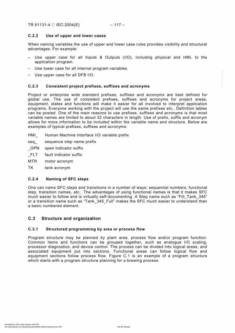
TR 61131-4 IEC:2004(E) – 117 –
C.2.2 Use of upper and lower cases
When naming variables the use of upper and lower case rules provides visibility and structural advantages. For example:
– Use upper case for all Inputs & Outputs (I/O), including physical and HMI, to the application program.
– Use lower case for all internal program variables. – Use upper case for all DFB I/O.
C.2.3 Consistent project prefixes, suffixes and acronyms
Project or enterprise wide standard prefixes, suffixes and acronyms are best defined for global use. The use of consistent prefixes, suffixes and acronyms for project areas, equipment, states and functions will make it easier for all involved to interpret application programs. Everyone working with the project will use the same prefixes etc.. Definition tables can be posted. One of the main reasons to use prefixes, suffixes and acronyms is that most variable names are limited to about 32 characters in length. Use of prefix, suffix and acronym allows for more information to be included within the variable name and structure. Below are examples of typical prefixes, suffixes and acronyms:
HMI_ Human Machine Interface I/O variable prefix seq_ sequence step name prefix _OPN open indicator suffix _FLT fault indicator suffix MTR motor acronym TK tank acronym
C.2.4 Naming of SFC steps
One can name SFC steps and transitions in a number of ways: sequential numbers, functional step, transition names, etc.. The advantages of using functional names is that it makes SFC much easier to follow and is virtually self-documenting. A Step name such as “Fill_Tank_345” or a transition name such as “Tank_345_Full” makes the SFC much easier to understand than a basic numbered element.
C.3 Structure and organization
C.3.1 Structured programming by area or process flow
Program structure may be planned by plant area, process flow and/or program function. Common items and functions can be grouped together, such as analogue I/O scaling, processor diagnostics, and device control. The process can be divided into logical areas, and associated equipment put into sections. Functional areas can follow logical flow and equipment sections follow process flow. Figure C.1 is an example of a program structure which starts with a program structure planning for a brewing process.
Copyright International Electrotechnical Commission Provided by IHS under license with IEC
Not for ResaleNo reproduction or networking permitted without license from IHS
--``````-`-`,,`,,`,`,,`---
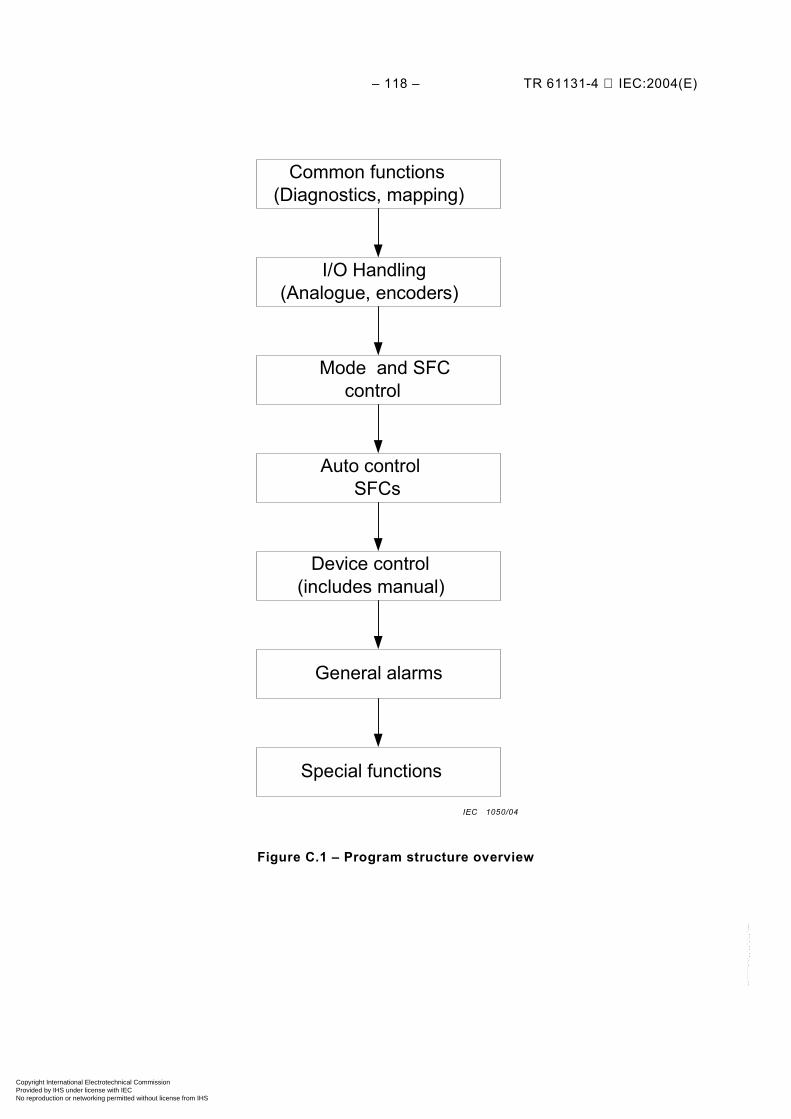
– 118 – TR 61131-4 IEC:2004(E)
I/O Handling(Analogue, encoders)
Mode and SFCcontrol
Auto controlSFCs
Device control(includes manual)
General alarms
Special functions
Common functions(Diagnostics, mapping)
Figure C.1 – Program structure overview
IEC 1050/04
Copyright International Electrotechnical Commission Provided by IHS under license with IEC
Not for ResaleNo reproduction or networking permitted without license from IHS
--``````-`-`,,`,,`,`,,`---
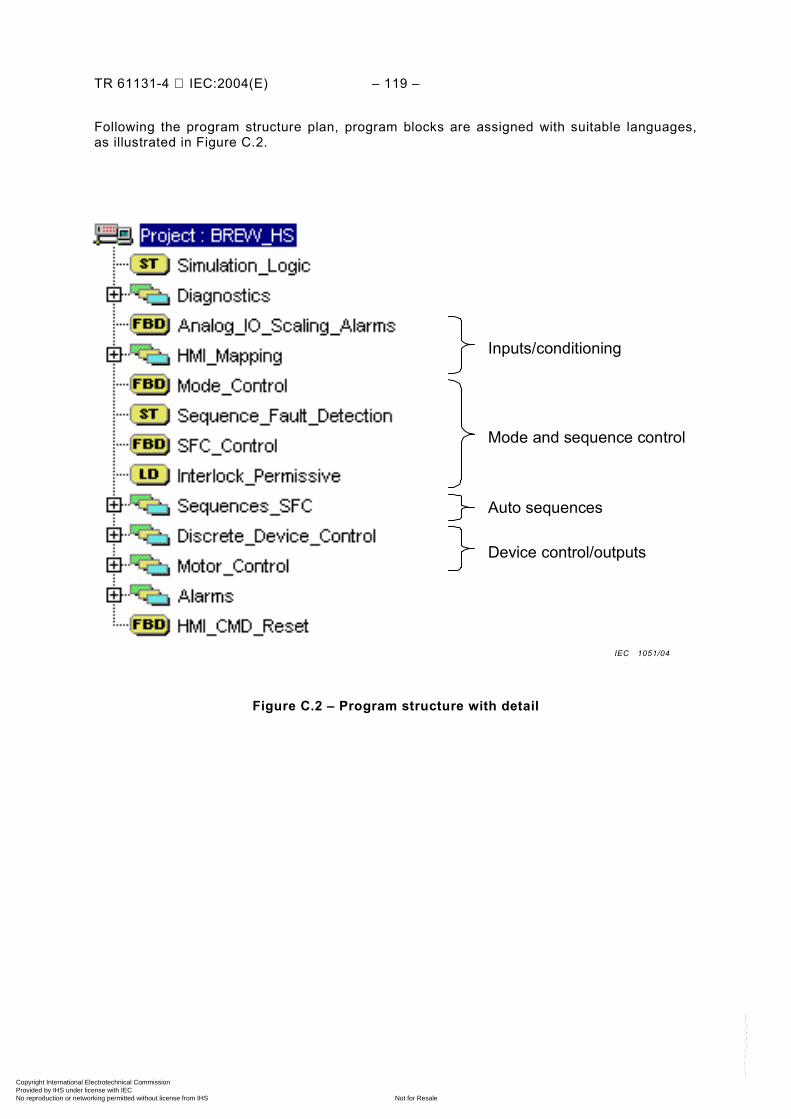
TR 61131-4 IEC:2004(E) – 119 –
Following the program structure plan, program blocks are assigned with suitable languages, as illustrated in Figure C.2.
Figure C.2 – Program structure with detail
Mode and sequence control
Inputs/conditioning
Auto sequences
Device control/outputs
IEC 1051/04
Copyright International Electrotechnical Commission Provided by IHS under license with IEC
Not for ResaleNo reproduction or networking permitted without license from IHS
--``````-`-`,,`,,`,`,,`---
– 120 – TR 61131-4 IEC:2004(E)
C.3.2 Structured variables (data types) for multiple devices
Common functions or devices can be assigned with structured variables to simplify program presentation, data manipulation and save on program implementation time. This is illustrated with the example structure variable for an analogue input below. All similar analogue inputs can then use the same structure.
analogPV: STRUCT
PV: INT; (* Analogue Process Variable – current value *) LL: INT; (* Analogue PV – Low Low Alarm Set Point *) LO: INT; (* Analogue PV – Low Alarm Set Point *) HI: INT; (* Analogue PV – High Alarm Set Point *) HH: INT; (* Analogue PV – High High Alarm Set Point *) AL: WORD; (* Analogue PV – Alarm Word *) (* Bit 0 – Low Low Alarm
Bit 1 – Low Alarm Bit 2 – High Alarm Bit 3 – High High Alarm Bit 4 – Broken Wire Alarm *)
C.3.3 Data arrays for data storage and manipulation
A data array can be the best way to handle repetitive or large quantities of data. When planning a structured application program, data storage and manipulation require early consideration. Arrayed data can make data storage and manipulation simple and efficient. If not planned at an early stage, it can be very costly to rearrange the project database structure partway thorough the project. It is therefore advisable to include data array planning at the program structuring stage.
C.4 Use of PLC languages
C.4.1 Combination of languages in one application program
PLC programming languages proscribed in the IEC 61131 series provides flexibility and can adapt to most automation programming requirements. Some examples are shown in this Clause. Taking up from the discussions in Clause C.2, the brewing process control can be detailed as shown in Figure C.3.
Copyright International Electrotechnical Commission Provided by IHS under license with IEC
Not for ResaleNo reproduction or networking permitted without license from IHS
--``````-`-`,,`,,`,`,,`---

TR 61131-4 IEC:2004(E) – 121 –
Figure C.3 – The structured program plan for brewing process automation with various languages
IEC 1052/04
Copyright International Electrotechnical Commission Provided by IHS under license with IEC
Not for ResaleNo reproduction or networking permitted without license from IHS
--``````-`-`,,`,,`,`,,`---
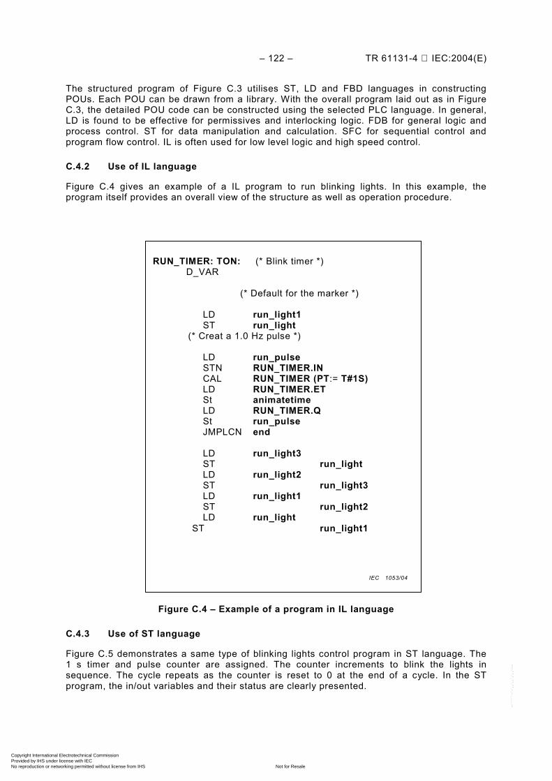
– 122 – TR 61131-4 IEC:2004(E)
The structured program of Figure C.3 utilises ST, LD and FBD languages in constructing POUs. Each POU can be drawn from a library. With the overall program laid out as in Figure C.3, the detailed POU code can be constructed using the selected PLC language. In general, LD is found to be effective for permissives and interlocking logic. FDB for general logic and process control. ST for data manipulation and calculation. SFC for sequential control and program flow control. IL is often used for low level logic and high speed control.
C.4.2 Use of IL language
Figure C.4 gives an example of a IL program to run blinking lights. In this example, the program itself provides an overall view of the structure as well as operation procedure.
Figure C.4 – Example of a program in IL language
C.4.3 Use of ST language
Figure C.5 demonstrates a same type of blinking lights control program in ST language. The 1 s timer and pulse counter are assigned. The counter increments to blink the lights in sequence. The cycle repeats as the counter is reset to 0 at the end of a cycle. In the ST program, the in/out variables and their status are clearly presented.
RUN_TIMER: TON: (* Blink timer *)
D_VAR
(* Default for the marker *)
LD run_light1 ST run_light (* Creat a 1.0 Hz pulse *) LD run_pulse STN RUN_TIMER.IN CAL RUN_TIMER (PT:= T#1S) LD RUN_TIMER.ET St animatetime LD RUN_TIMER.Q St run_pulse JMPLCN end LD run_light3 ST run_light LD run_light2 ST run_light3 LD run_light1 ST run_light2 LD run_light ST run_light1
IEC 1053/04
Copyright International Electrotechnical Commission Provided by IHS under license with IEC
Not for ResaleNo reproduction or networking permitted without license from IHS
--``````-`-`,,`,,`,`,,`---
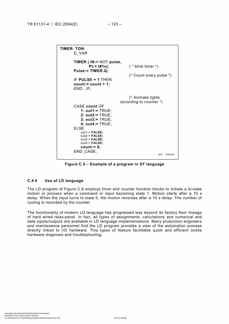
TR 61131-4 IEC:2004(E) – 123 –
Figure C.5 – Example of a program in ST language
C.4.4 Use of LD language
The LD program of Figure C.6 employs timer and counter function blocks to initiate a bi-state motion or process when a command or input becoming state 1. Motion starts after a 10 s delay. When the input turns to state 0, the motion reverses after a 10 s delay. The number of cycling is recorded by the counter.
The functionality of modern LD language has progressed way beyond its factory floor lineage of hard wired relay-panel. In fact, all types of assignments, calculations and numerical and data inputs/outputs are available in LD language implementations. Many production engineers and maintenance personnel find the LD program provides a view of the automation process directly linked to I/O hardware. This types of feature facilitates quick and efficient onsite hardware diagnosis and troubleshooting.
TIMER: TON: D_VAR TIMER ( IN:= NOT pulse, Pt:= t#1s); ( * blink timer *) Pulse:= TIMER.Q; (* Count every pulse *) IF PULSE = 1 THEN
count:= count + 1; END…IF;
(* Animate lights according to counter *)
CASE count OF 1: out1:= TRUE; 2: out2:= TRUE; 3: out3:= TRUE; 4: out4:= TRUE;
ELSE out1:= FALSE; out2:= FALSE; out3:= FALSE; out4:= FALSE; count:= 0; END_CASE; IEC 1054/04
Copyright International Electrotechnical Commission Provided by IHS under license with IEC
Not for ResaleNo reproduction or networking permitted without license from IHS
--``````-`-`,,`,,`,`,,`---
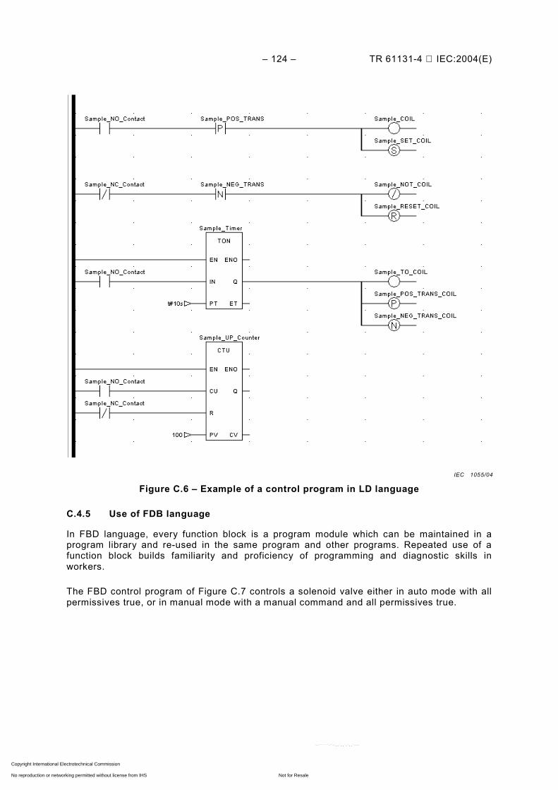
– 124 – TR 61131-4 IEC:2004(E)
Figure C.6 – Example of a control program in LD language
C.4.5 Use of FDB language
In FBD language, every function block is a program module which can be maintained in a program library and re-used in the same program and other programs. Repeated use of a function block builds familiarity and proficiency of programming and diagnostic skills in workers.
The FBD control program of Figure C.7 controls a solenoid valve either in auto mode with all permissives true, or in manual mode with a manual command and all permissives true.
IEC 1055/04
Copyright International Electrotechnical Commission Provided by IHS under license with IEC
Not for ResaleNo reproduction or networking permitted without license from IHS
--``````-`-`,,`,,`,`,,`---
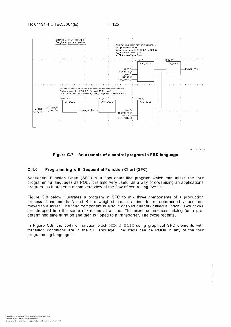
TR 61131-4 IEC:2004(E) – 125 –
Figure C.7 – An example of a control program in FBD language
C.4.6 Programming with Sequential Function Chart (SFC)
Sequential Function Chart (SFC) is a flow chart like program which can utilise the four programming languages as POU. It is also very useful as a way of organising an applications program, as it presents a complete view of the flow of controlling events.
Figure C.8 below illustrates a program in SFC to mix three components of a production process. Components A and B are weighed one at a time to pre-determined values and moved to a mixer. The third component is a solid of fixed quantity called a “brick”. Two bricks are dropped into the same mixer one at a time. The mixer commences mixing for a pre-determined time duration and then is tipped to a transporter. The cycle repeats.
In Figure C.8, the body of function block MIX_2_BRIX using graphical SFC elements with transition conditions are in the ST language. The steps can be POUs in any of the four programming languages.
IEC 1056/04
Copyright International Electrotechnical Commission Provided by IHS under license with IEC
Not for ResaleNo reproduction or networking permitted without license from IHS
--``````-`-`,,`,,`,`,,`---
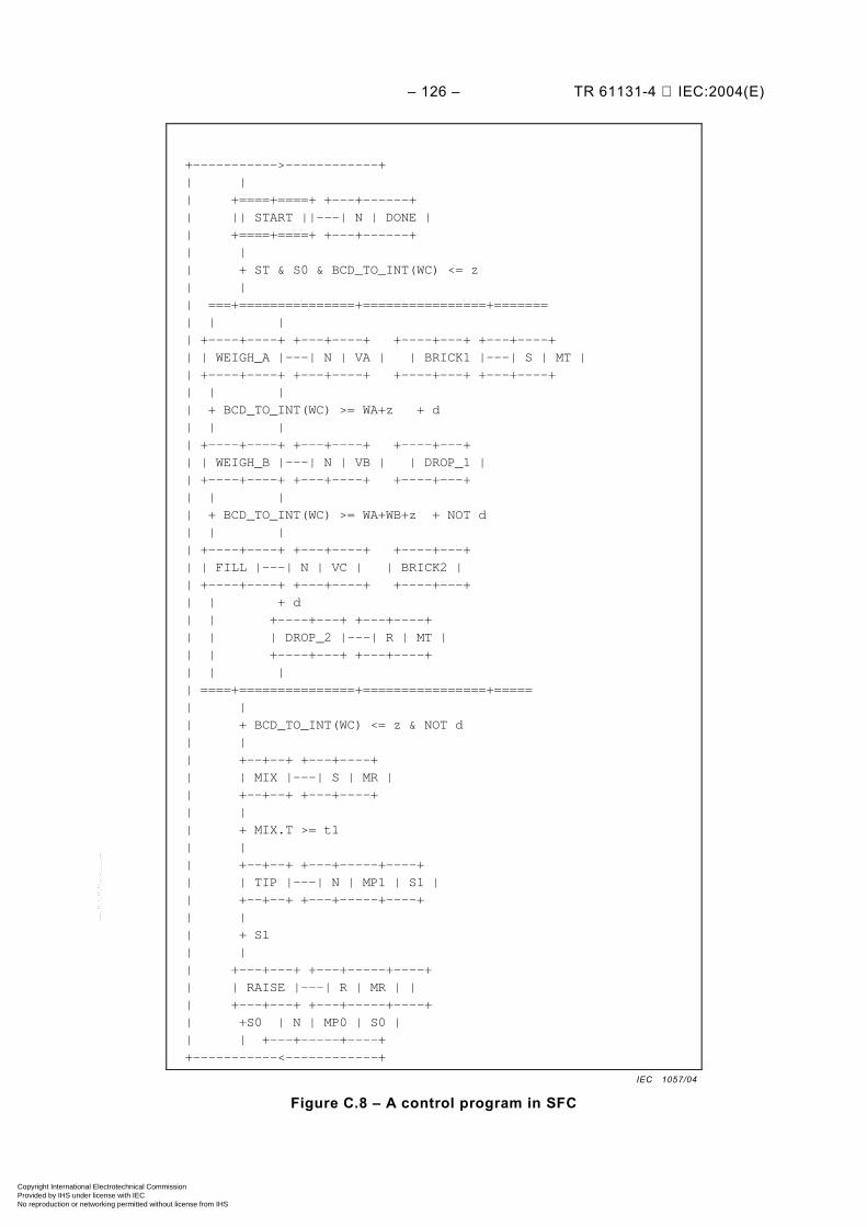
– 126 – TR 61131-4 IEC:2004(E)
+----------->------------+
| |
| +====+====+ +---+------+
| || START ||---| N | DONE |
| +====+====+ +---+------+
| |
| + ST & S0 & BCD_TO_INT(WC) <= z
| |
| ===+===============+================+=======
| | |
| +----+----+ +---+----+ +----+---+ +---+----+
| | WEIGH_A |---| N | VA | | BRICK1 |---| S | MT |
| +----+----+ +---+----+ +----+---+ +---+----+
| | |
| + BCD_TO_INT(WC) >= WA+z + d
| | |
| +----+----+ +---+----+ +----+---+
| | WEIGH_B |---| N | VB | | DROP_1 |
| +----+----+ +---+----+ +----+---+
| | |
| + BCD_TO_INT(WC) >= WA+WB+z + NOT d
| | |
| +----+----+ +---+----+ +----+---+
| | FILL |---| N | VC | | BRICK2 |
| +----+----+ +---+----+ +----+---+
| | + d
| | +----+---+ +---+----+
| | | DROP_2 |---| R | MT |
| | +----+---+ +---+----+
| | |
| ====+===============+================+=====
| |
| + BCD_TO_INT(WC) <= z & NOT d
| |
| +--+--+ +---+----+
| | MIX |---| S | MR |
| +--+--+ +---+----+
| |
| + MIX.T >= t1
| |
| +--+--+ +---+-----+----+
| | TIP |---| N | MP1 | S1 |
| +--+--+ +---+-----+----+
| |
| + S1
| |
| +---+---+ +---+-----+----+
| | RAISE |---| R | MR | |
| +---+---+ +---+-----+----+
| +S0 | N | MP0 | S0 |
| | +---+-----+----+
+-----------<------------+
Figure C.8 – A control program in SFC
IEC 1057/04
Copyright International Electrotechnical Commission Provided by IHS under license with IEC
Not for ResaleNo reproduction or networking permitted without license from IHS
--``````-`-`,,`,,`,`,,`---
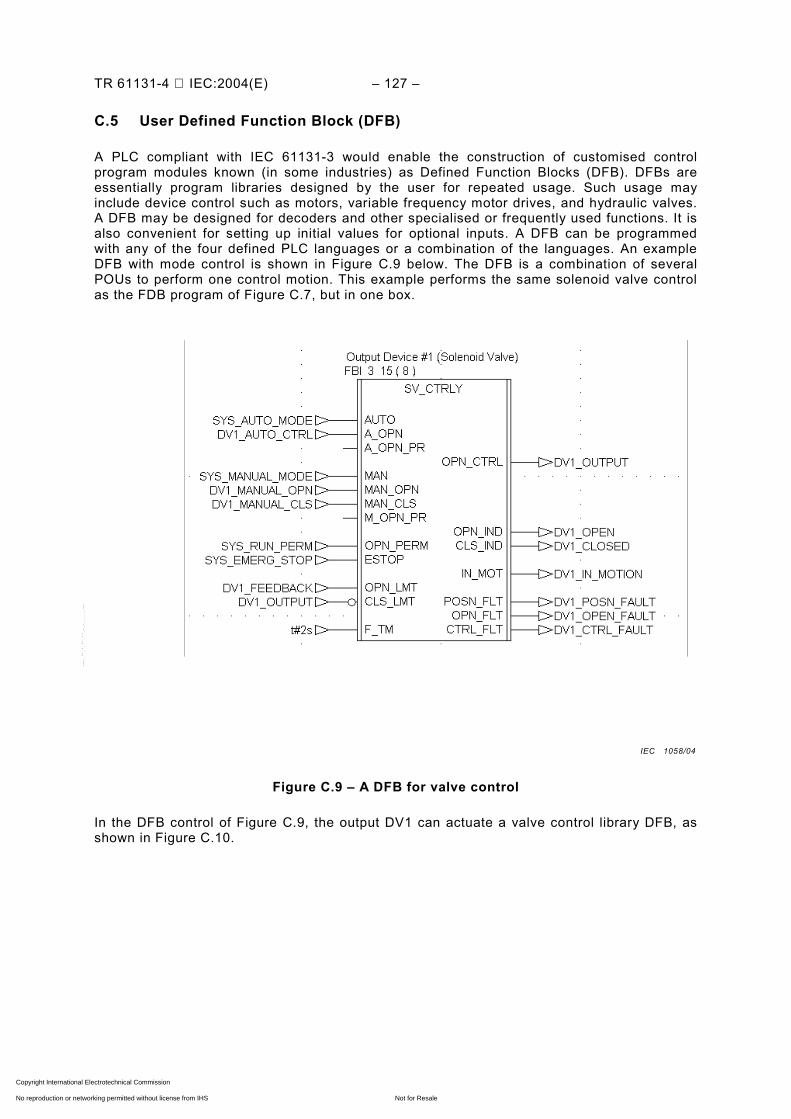
TR 61131-4 IEC:2004(E) – 127 –
C.5 User Defined Function Block (DFB)
A PLC compliant with IEC 61131-3 would enable the construction of customised control program modules known (in some industries) as Defined Function Blocks (DFB). DFBs are essentially program libraries designed by the user for repeated usage. Such usage may include device control such as motors, variable frequency motor drives, and hydraulic valves. A DFB may be designed for decoders and other specialised or frequently used functions. It is also convenient for setting up initial values for optional inputs. A DFB can be programmed with any of the four defined PLC languages or a combination of the languages. An example DFB with mode control is shown in Figure C.9 below. The DFB is a combination of several POUs to perform one control motion. This example performs the same solenoid valve control as the FDB program of Figure C.7, but in one box.
Figure C.9 – A DFB for valve control
In the DFB control of Figure C.9, the output DV1 can actuate a valve control library DFB, as shown in Figure C.10.
IEC 1058/04
Copyright International Electrotechnical Commission Provided by IHS under license with IEC
Not for ResaleNo reproduction or networking permitted without license from IHS
--``````-`-`,,`,,`,`,,`---
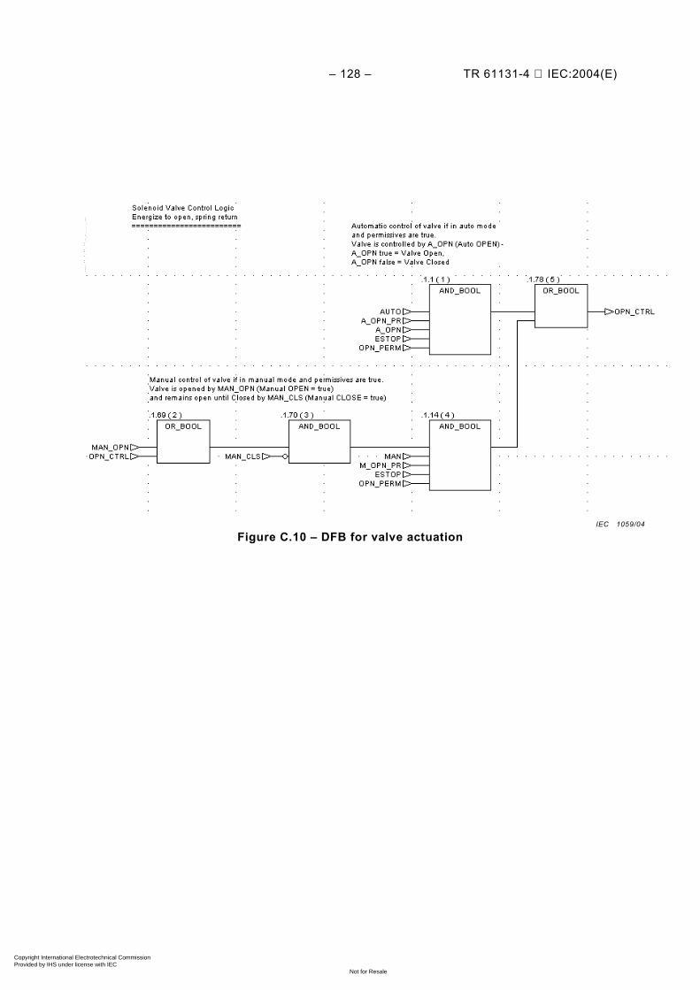
– 128 – TR 61131-4 IEC:2004(E)
Figure C.10 – DFB for valve actuation IEC 1059/04
Copyright International Electrotechnical Commission Provided by IHS under license with IEC
Not for ResaleNo reproduction or networking permitted without license from IHS
--``````-`-`,,`,,`,`,,`---
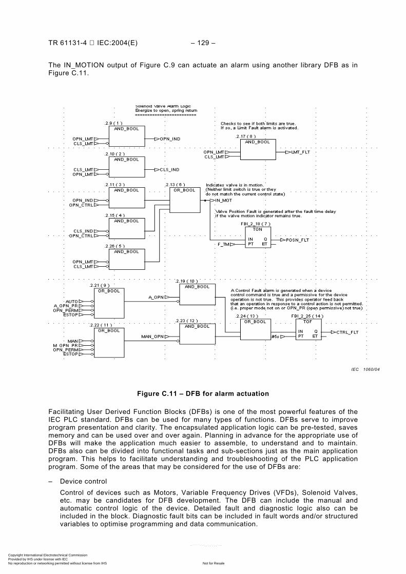
TR 61131-4 IEC:2004(E) – 129 –
The IN_MOTION output of Figure C.9 can actuate an alarm using another library DFB as in Figure C.11.
Figure C.11 – DFB for alarm actuation
Facilitating User Derived Function Blocks (DFBs) is one of the most powerful features of the IEC PLC standard. DFBs can be used for many types of functions. DFBs serve to improve program presentation and clarity. The encapsulated application logic can be pre-tested, saves memory and can be used over and over again. Planning in advance for the appropriate use of DFBs will make the application much easier to assemble, to understand and to maintain. DFBs also can be divided into functional tasks and sub-sections just as the main application program. This helps to facilitate understanding and troubleshooting of the PLC application program. Some of the areas that may be considered for the use of DFBs are:
– Device control Control of devices such as Motors, Variable Frequency Drives (VFDs), Solenoid Valves,
etc. may be candidates for DFB development. The DFB can include the manual and automatic control logic of the device. Detailed fault and diagnostic logic also can be included in the block. Diagnostic fault bits can be included in fault words and/or structured variables to optimise programming and data communication.
IEC 1060/04
Copyright International Electrotechnical Commission Provided by IHS under license with IEC
Not for ResaleNo reproduction or networking permitted without license from IHS
--``````-`-`,,`,,`,`,,`---
– 130 – TR 61131-4 IEC:2004(E)
– Frequently used functions Frequently used functions, such as Analogue I/O Scaling with diagnostics, and repetitive
logic or calculations are good candidates for DFB development. – Special functions Even though a special function may only be used once or twice in an application, its DFB
development may be considered to encapsulate its application logic for security or the simplification of the program presentation.
C.6 Language implementation
In practice, a PLC system selected for any particular control function requires only some of the features specified in IEC 61131-3. It is not necessary to fulfil a complete set of requirements of IEC 61131-3 for any particular application. The standard allows partial implementations of the language standard. This covers the number of supported languages, functions and function blocks. However, conflicts with this standard or substitutes to this standard are not permitted. This aspect needs to be taken into consideration during the user’s selection process.
Many programming environments offer enhanced convenient features, e.g.: mouse operation, pull down menus, graphical programming screens, support for multiple windows, built in hypertext functions, facilities for verification during design and on-line program modifications. This is not specified within the standard itself: it is one of the aspects that manufacturers can differentiate.
In summary, PLC application programming with IEC standardized PLC languages insures a basic level of software functionality. Its extent, however, is not limited to the basic level. It also has the advantage of universal syntax and semantics which facilitates portability. In addition, IEC 61131-3 is so structured that it permits programming innovations and management, thereby greatly enhancing productivity and efficiency of the PLC application.
___________
Copyright International Electrotechnical Commission Provided by IHS under license with IEC
Not for ResaleNo reproduction or networking permitted without license from IHS
--``````-`-`,,`,,`,`,,`---

Standards Survey
The IEC would like to offer you the best quality standards possible. To make sure that wecontinue to meet your needs, your feedback is essential. Would you please take a minuteto answer the questions overleaf and fax them to us at +41 22 919 03 00 or mail them tothe address below. Thank you!
Customer Service Centre (CSC)
International Electrotechnical Commission3, rue de Varembé1211 Genève 20Switzerland
or
Fax to: IEC/CSC at +41 22 919 03 00
Thank you for your contribution to the standards-making process.
Non affrancareNo stamp required
Nicht frankierenNe pas affranchir
A Prioritaire
RÉPONSE PAYÉE
SUISSE
Customer Service Centre (CSC)International Electrotechnical Commission3, rue de Varembé1211 GENEVA 20Switzerland
Copyright International Electrotechnical Commission Provided by IHS under license with IEC
Not for ResaleNo reproduction or networking permitted without license from IHS
--``````-`-`,,`,,`,`,,`---
Q1 Please report on ONE STANDARD andONE STANDARD ONLY . Enter the exactnumber of the standard: (e.g. 60601-1-1)
.............................................................
Q2 Please tell us in what capacity(ies) youbought the standard (tick all that apply).I am the/a:
purchasing agent R
librarian R
researcher R
design engineer R
safety engineer R
testing engineer R
marketing specialist R
other.....................................................
Q3 I work for/in/as a:(tick all that apply)
manufacturing R
consultant R
government R
test/certification facility R
public utility R
education R
military R
other.....................................................
Q4 This standard will be used for:(tick all that apply)
general reference R
product research R
product design/development R
specifications R
tenders R
quality assessment R
certification R
technical documentation R
thesis R
manufacturing R
other.....................................................
Q5 This standard meets my needs:(tick one)
not at all R
nearly R
fairly well R
exactly R
Q6 If you ticked NOT AT ALL in Question 5the reason is: (tick all that apply)
standard is out of date R
standard is incomplete R
standard is too academic R
standard is too superficial R
title is misleading R
I made the wrong choice R
other ....................................................
Q7 Please assess the standard in thefollowing categories, usingthe numbers:(1) unacceptable,(2) below average,(3) average,(4) above average,(5) exceptional,(6) not applicable
timeliness .............................................quality of writing....................................technical contents.................................logic of arrangement of contents ..........tables, charts, graphs, figures ...............other ....................................................
Q8 I read/use the: (tick one)
French text only R
English text only R
both English and French texts R
Q9 Please share any comment on anyaspect of the IEC that you would likeus to know:
............................................................
............................................................
............................................................
............................................................
............................................................
............................................................
............................................................
............................................................
............................................................
............................................................
............................................................
............................................................
Copyright International Electrotechnical Commission Provided by IHS under license with IEC
Not for ResaleNo reproduction or networking permitted without license from IHS
--``````-`-`,,`,,`,`,,`---

Copyright International Electrotechnical Commission Provided by IHS under license with IEC
Not for ResaleNo reproduction or networking permitted without license from IHS
--``````-`-`,,`,,`,`,,`---

ISBN 2-8318-7597-8
-:HSMINB=]\Z^\W:ICS 25.040.40; 35.240.50
Typeset and printed by the IEC Central Office GENEVA, SWITZERLAND
Copyright International Electrotechnical Commission Provided by IHS under license with IEC
Not for ResaleNo reproduction or networking permitted without license from IHS
--``````-`-`,,`,,`,`,,`---