technical handbook - thermal insulation fixings – facade · thera insuation fixings fi facade e...
TRANSCRIPT

THERMAL INSULATION FIXINGS – FACADE
LA CHEVILLENYLON MULTIFONCTIONS
337
F
General information for correct design, installation and use of facade thermal insulation systems 338
TFIX-8ST – A versatile screw-in facade fastener with self-embedding features 342
TFIX-8S – A versatile screw-in facade fastener 344
TFIX-8M – A versatile hammer-in facade fastener 346
KI-10 – Insulation fixing with standard expansion zone and plastic nail 348
KI-10M – Insulation fixing with standard expansion zone and metal nail 350
KI-10N – Insulation fixing with long expansion zone 352
KI-10NS – Insulation fixing with long expansion zone and screw 354
MKI+MKC – Fireproof connector for EPS and mineral wool installation 356
MKI-A2+MKC – Stainless steel fireproof connector for EPS and mineral wool installation
458
KC+UC – Holding flange with screw for insulation fixed to timber 360
KC+WB – Holding flange with screw for insulation fixed to steel 362
KIK – Single fixing for insulation installed in zones without wind forces 364
KWL – Insulation holding flange for KI, TFIX & KC fixings 365

THERMAL INSULATION FIXINGS – FACADE
LA CHEVILLENYLON MULTIFONCTIONS
AA338
F
3. Failure load causing removal of insulation material from substrateThe force magnitude causing insulation material to tear away from the substrate (over the clamp-
ing flange) depends on the strength and thickness of the thermal insulation material applied. In structural calculations the maximum value of this force cannot be greater than the tensile
load design resistance of the fixings. The tensile performance of the fixing is dependent upon the friction between the connector’s expansion sleeve and the internal surface of the pre-drilled hole
GENERAL INFORMATION FOR CORRECT DESIGN, INSTALLATION AND USE OF FACADE THERMAL INSULATION SYSTEMS
1. Reasons for mechanical fixing application in case of wall insulationThere is a requirement for mechanical fixing application during wall insulation using an adhesive
layer.The external building facade is subject to suction – caused by wind and shear loads. Wind suction
force is the most common cause of insulation detachment from substrate. Distortion of the whole facade surface causes internal cracking of the adhesive structure and, consequently, appearance of cracks in rendering. Use of mechanical fixings can effectively reduce these effects.
2. The most commonly made mistakes are:• Improper surface preparation:
- no surface cleaning (removal of dust and oil)- failure to remove old or loose paint, plaster or rendering elements- failure to prepare a level surface and improper preparation of strongly absorbent substrates- insufficient substrate resistance
• Mistakesmadeduringpreparationandapplicationofadhesive(failuretofollowrecommend-ed proportions, ‘thinning’ and improper adhesive layer distribution)
• Failuretoobserverequiredhardeningtimeforadhesive• Failuretoworkwithinrecommendedambienttemperaturerange(mostcommonlyfrom+5°C
upto+25°C)• Workcarriedoutinadverseweatherconditions(precipitation,strongwinds,directexposureto
sun)• Leavingunfinishedworkduringwinter
Styropian Wełna mineralna Wełna lamelowa Wełna drzewna Korek Płyty z lekkich materiałów
z recyklingu
Blacha trapezowa
Expandedpolystyrene(EPS)Mineralwool Lamellawool
Lightpanelsmadeof recycled materials
Wood wool Cork
Trapezoidal sheet
THERMAL INSULATION MATERIALS:
Styropian Wełna mineralna Wełna lamelowa Wełna drzewna Korek Płyty z lekkich materiałów
z recyklingu

THERMAL INSULATION FIXINGS – FACADE
LA CHEVILLENYLON MULTIFONCTIONS
339
F
in the substrate. This load bearing capacity depends on substrate type and connector anchoring depth. Overall length and flange diameter of the connector do not influence performance. The fix-ing design, when expanded, possesses a greater diameter at the frictional interface (approximately 1-2 mm) than at the connector’s core diameter.
4. Connector anchoring depthFor connector application in base materials such as concrete or solid brickwork, the minimum
anchoring depth is 25mm. In the case of materials like hollow brickwork, structural clay block, lightweight concrete and aerated concrete blocks, fasteners require an anchoring depth of 60 mm. Drilling depth should exceed anchorage depth (usually by 10 mm in case of 8-10 mm drill diameter) in order to ensure debris is sufficiently cleared and full embedment can be achieved.
5. Required connector lengthWhen selecting the length of connector the following should be considered: A – thickness of insulation material,B – anchoring depth in load-bearing substrate,C – thickness of existing render (if applicable),D – thickness of adhesive,E – surface roughness,F – tolerance for work inaccuracy
L = A + B + C + D + E + F
6. Heat transfer coefficient and thermal bridge formationApplication of connectors with a metal insert pin causes formation of thermal bridges, caused
by the relatively high thermal conductivity of steel. Any resultant limitation on thermal insulation efficiency is practically eliminated thanks to a special plastic overmoulding on the head of the nail. Heat loss through the nail is therefore below the admissible limit. Furthermore, the plastic head component has the additional benefit of enhanced corrosion protection.
Alternatively, connectors with a plastic pin can in some cases be applied. However this applica-tion is limited due to significantly reduced mechanical resistance.
7. Edge zone determinationThe facade’s edge zone is defined by the external building dimensions. The narrowest span of the
building should be taken into account.The edge zone value equates to 1/8 of that span (A) and is constrained in the range of 1 to 2 m.
1m ≤ A/8 ≤ 2m
The quantity of fixings applied in the edge zone must be increased by 20%-50%.
In some cases – especially for particularly high buildings – a detailed scheme of the spacing and quantity of fixings should be prepared in collaboration with the thermal insulation system manufacturer.

THERMAL INSULATION FIXINGS – FACADE
LA CHEVILLENYLON MULTIFONCTIONS
AA340
F
8. Connector quantity and spacingQuantity and spacing are important parameters which determine the durability and safety of a facade.Laboratoryresearchhasshownthatconnectorspacingdependson:
• Weightoftheinsulationmaterial(includingadhesive,meshandplaster) • Load-bearingsubstratematerial • Heightofinsulatedbuilding
üapplicable
û not applicable*KWLtypeflangesareusedwithKIfixingswithsteelpin
Fixing type Polystyrene MineralwoolNumber of anchors per m2, depending on the height
of the building
H < 8 m 8 m < H < 20 m H > 20 m
TFIX-8M ü ü 4-5/6-8 pcs 6-8/8-10 pcs û/10-12 pcs
TFIX-8S ü ü 4-5/6-8 pcs 6-8/8-10 pcs û/10-12 pcs
TFIX-8ST ü ü 4-5/6-8 pcs 6-8/8-10 pcs û/10-12 pcs
KI-10 ü û 4-5 pcs 6-8 pcs ûKI-8M ü ü 4-5/6-8 pcs 6-8/8-10 pcs û/10-12 pcs
KI-10N ü ü 4-5/6-8 pcs 6-8/8-10 pcs û/10-12 pcs
KC ü ü 4-5/6-8 pcs û ûKWL* û ü 3-5 pcs 3-5 pcs û
EXAMpLE OF MECHANICAL FIXINGS SpACING
example of fixings spacing in case of mineral wool
example of fixings spacing in case of polystyrene

THERMAL INSULATION FIXINGS – FACADE
LA CHEVILLENYLON MULTIFONCTIONS
341
F
9. Installation of insulation layerThe mechanical installation of insulation panels should take place after adhesion, taking into
consideration the manufacturer’s recommended curing time (not earlier than after 24 hours).Fixings quantity and spacing should be specified in technical drawings or specified by thermal
insulation system-provider. The quantity should not be less than 4 pcs/m2.In concrete and solid brickwork substrates drilling should be performed perpendicular to the
surface, through pre-applied polystyrene foam or mineral wool insulation panels. Holes should possessadiameterequaltotheconnector’ssleevediameter(withtolerancesof+0.1and-0.3mm)and be drilled according to the quantity and spacing specified in point 8.
When drilling holes in concrete, a rotary percussion drilling machine should be used with sintered carbide-tipped drills.
Holes in hollow brickwork and aerated concrete should be drilled using a rotary drilling machine without hammer action.
Depth of drilled holes must be 10 mm deeper than anchoring depth.To avoid damage at the reverse of the substrate, the wall thickness must be minimum 20 mm,
(30-40 mm in case of concrete) greater than the drilled hole depth.In situations when repeat drilling is required due to error, the distance from the original hole loca-
tion must be at least equal to actual hole depth.Before installing the connector holes should be cleaned - debris and dust can be removed using
an air pump, round brush or vacuum.Subsequently fixings can be placed in the hole and lightly hammered.During installation proper clamping of insulation panels to the substrate must be ensured. The
expansion nail is then hammered through the connector until the head is flush with the facade. Permanent fixing in the substrate is thus achieved.
Proper fixing of the connector can be assumed when it is fastened tightly in the substrate. When using products with a screw-in nail, further screwing will not be possible.Note: insulation fixings with a plastic pin are intended only for fastening light thermo-insulation
materials, for example polystyrene foam.Connectors with a steel pin are also suitable for fastening polystyrene foam, but are intended
for heavy insulation materials (for example mineral wool, when only this type of fixing should be applied). This is due to the requirement for high shear and bending resistance, which is provided in this case by the zinc-plated steel pin component. An additional advantage of the connector with steel pin is the added safety in the case of fire exposure where, after the plastic sleeve has melted, the connector nail continues to transmit shear and bending loads.
The high quality of these insulation fixings is proven by ITB technical recommendation RT ITB 1028/2005.

THERMAL INSULATION FIXINGS – FACADE
LA CHEVILLENYLON MULTIFONCTIONS
AA342
F
tfix-8st
BASE MATERIAL:• Concrete (A) C12/15 - C50/60 acc. EN 206-1• ClaybrickMZ(B)min12MPaacc.EN771-1• Sand-limesolidbrickKS(B)min12MPaacc.DIN106• Sand-limeperforatedbrickKSL(C)min12MPaacc.DIN106• VerticallyperforatedclaybrickHLz(C)acc.DINV105• LightweightconcretehollowblockHBl(D)min2MPaacc.DIN18151• LightweightconcretesolidbrickV(D)min4MPaacc.DIN18151• Prefabricated reinforced components of lightweight aggregate concrete(LAC)4MPa,6MPa
• AutoclavedaeratedconcreteAAC(E)4MPa,6MPaacc.DINV4165
FEATURES:pLASTIC SLEEVE:• PolypropyleneFOAM pAD:• Cross-linked polyolefinSTEEL SCREW:• Zincelectroplatedcarbonsteel• Coating thickness min 5µm• Nylon head piece with TORX 40 drive
AppROVALS AND REpORTS:• ETA-11/0144
Size Product Code
Fixing Fixture
Diameter Length Plate diameter Min.thickness Max.thickness
d L D tfix A, B, C, D tfix E tfix A, B, C, D tfix E
[mm] [mm] [mm] [mm] [mm] [mm] [mm]
Ø8
TFIX-8ST-115 8 115 60 80 40 100 60
TFIX-8ST--135 8 135 60 100 60 120 80
TFIX-8ST-155 8 155 60 120 80 140 100
TFIX-8ST-175 8 175 60 140 100 160 120
TFIX-8ST-195 8 195 60 160 120 180 140
TFIX-8ST-215 8 215 60 180 140 200 160
TFIX-8ST-235 8 235 60 200 160 220 180
TFIX-8ST-255 8 255 60 220 180 240 200
TFIX-8ST-275 8 275 60 240 200 260 220
TFIX-8ST-295 8 295 60 260 220 280 240
TFIX-8ST-335 8 335 60 300 260 320 280
TFIX-8ST TFIX-PERFORATOR
TFIX-8ST – Screw-in facade fastener with self-embedding features
LA CHEVILLENYLON MULTIFONCTIONS
P R O D U C t i N f O R M At i O N
LA CHEVILLENYLON MULTIFONCTIONS
i N s tA L L At i O N DAtA

THERMAL INSULATION FIXINGS – FACADE
LA CHEVILLENYLON MULTIFONCTIONS
343
F
tfix-8st
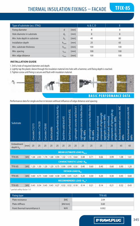
1. Drill a hole of required diameter and depth.2.Lightlytaptheplasticsleevethroughtheinsulationmaterialintoholewithahammer,untilfixingdepthisreached.3. Tighten screw until fixing is secure and flush with insulation material.
INSTALLATION GUIDE
Type of substrate (acc. ETAG) A, B, C, D EFixing diameter d [mm] 8 8
Hole diameter in substrate d0 [mm] 8 8
Min.holedepthinsubstrate h0 [mm] 40 80
Installation depth hnom [mm] 25 65
Min.substratethickness hmin [mm] 100 100
Min.spacing smin [mm] 100 100
Min.edgedistance cmin [mm] 100 100
Performance data for single anchor in tension without influence of edge distance and spacing
* partial safety factor 1.4
Substrate
Conc
rete
C12
/15
Conc
rete
≥ C
16/2
0
Conc
rete
C50
/60
Solid
bric
kMz
Verticallyperforatedcla
ybric
kHLz
Sand
-lim
e so
lid b
rick K
S
Sand
-lime pe
rforatedbrick
KSL
Lightweigh
tcon
cretesolid
bric
kV
Lightweigh
tcon
creteho
llowblock
HBL4
MPa
Lightweigh
tcon
creteho
llowblock
HBL6
MPa
Pref
abric
ated
rein
forc
ed co
mpo
nent
s of
light
wei
ght a
ggre
gate
conc
rete
4M
PaPr
efab
ricat
ed re
info
rced
com
pone
nts
of lig
htw
eigh
t agg
rega
te co
ncre
te
6MPa
Auto
clave
d ae
rate
d co
ncre
te A
AC
4MPa
Auto
clave
d ae
rate
d co
ncre
te A
AC
6MPa
Embedment depth hef
[mm] 25 25 25 25 25 25 25 25 25 25 25 25 65 65
MEAN ULTIMATE LOAD NRu,m
TFIX-8ST [kN] 1.64 2.03 1.74 1.68 0.94 1.32 1.15 0.64 0.48 0.71 0.66 0.99 1.08 1.61
CHARACTERISTIC LOAD NRk
TFIX-8ST [kN] 1.20 1.50 1.20 1.20 0.75 0.90 0.90 0.50 0.40 0.60 0.40 0.60 0.90 1.20
DESIGN LOAD NRd
TFIX-8ST [kN] 0.60 0.75 0.60 0.60 0.38 0.45 0.45 0.25 0.20 0.30 0.20 0.30 0.45 0.60
RECOMMENDED LOAD Nrec*
TFIX-8ST [kN] 0.43 0.54 0.43 0.43 0.27 0.32 0.32 0.18 0.14 0.21 0.14 0.21 0.32 0.43
Fixing type TFIX-8STPlate resistance [kN] 2.04
Plate stiffness [kN/mm] 0.60
Point thermal transmittance λ W/K 0.002
LA CHEVILLENYLON MULTIFONCTIONS
B A s i C P E R f O R M A N C E DAtA

THERMAL INSULATION FIXINGS – FACADE
LA CHEVILLENYLON MULTIFONCTIONS
AA344
F
tfix-8s
TFIX-8S
BASE MATERIAL:• Concrete (A) C12/15 - C50/60 acc. EN 206-1• ClaybrickMZ(B)min12MPaacc.EN771-1• Sand-limesolidbrickKS(B)min12MPaacc.DIN106• Sand-limeperforatedbrickKSL(C)min12MPaacc.DIN106• VerticallyperforatedclaybrickHLz(C)acc.DINV105• LightweightconcretehollowblockHBl(D)min2MPa
acc. DIN 18151• LightweightconcretesolidbrickV(D)min4MPaacc.DIN18151• Prefabricated reinforced components of lightweight aggregate concrete(LAC)4MPa,6MPa
• AutoclavedaeratedconcreteAAC(E)4MPa,6MPa acc. DIN V 4165
TFIX-8S – A versatile screw-in facade fastener
LA CHEVILLENYLON MULTIFONCTIONS
P R O D U C t i N f O R M At i O N
FEATURES:pLASTIC SLEEVE:• PolypropyleneSTEEL SCREW:• Zincelectroplatedcarbonsteel• Coating thickness min 5µm• Nylon head piece with TORX 40 drive
AppROVALS AND REpORTS:• ETA-11/0144
Size Product Code
Fixing Fixture
Diameter Length Plate diameter Min.thickness Max.thickness
d L D tfix A, B, C, D tfix E tfix A, B, C, D tfix E
[mm] [mm] [mm] [mm] [mm] [mm] [mm]
Ø8
TFIX-8S-115 8 115 60 80 40 100 60
TFIX-8S-135 8 135 60 100 60 120 80
TFIX-8S-155 8 155 60 120 80 140 100
TFIX-8S-175 8 175 60 140 100 160 120
TFIX-8S-195 8 195 60 160 120 180 140
TFIX-8S-215 8 215 60 180 140 200 160
TFIX-8S-235 8 235 60 200 160 220 180
TFIX-8S-255 8 255 60 220 180 240 200
TFIX-8S-275 8 275 60 240 200 260 220
TFIX-8S-295 8 295 60 260 220 280 240
TFIX-8S-335 8 335 60 300 260 320 280
LA CHEVILLENYLON MULTIFONCTIONS
i N s tA L L At i O N DAtA
THERMAL INSULATION FIXINGS – FACADE
LA CHEVILLENYLON MULTIFONCTIONS
345
F
tfix-8s
1. Drill a hole of required diameter and depth.2.Lightlytaptheplasticsleevethroughtheinsulationmaterialintoholewithahammer,untilfixingdepthisreached.3. Tighten screw until fixing is secure and flush with insulation material.
INSTALLATION GUIDE
Type of substrate (acc. ETAG) A, B, C, D EFixing diameter d [mm] 8 8
Hole diameter in substrate d0 [mm] 8 8
Min.holedepthinsubstrate h0 [mm] 40 80
Installation depth hnom [mm] 25 65
Min.substratethickness hmin [mm] 100 100
Min.spacing smin [mm] 100 100
Min.edgedistance cmin [mm] 100 100
Performance data for single anchor in tension without influence of edge distance and spacing
LA CHEVILLENYLON MULTIFONCTIONS
B A s i C P E R f O R M A N C E DAtA
* partial safety factor 1.4
Substrate
Conc
rete
C12
/15
Conc
rete
≥ C
16/2
0
Conc
rete
C50
/60
Solid
bric
kMz
Verticallyperforatedcla
ybric
kHLz
Sand
-lim
e so
lid b
rick K
S
Sand
-limepe
rforatedbrick
KSL
Lightweigh
tcon
cretesolid
bric
kV
Lightweigh
tcon
creteho
llowblock
HBL4
MPa
Lightweigh
t con
creteho
llowblock
HBL 6
MPa
Pref
abric
ated
rein
forc
ed
com
pone
nts o
f lig
htw
eigh
t ag
greg
ateconc
rete4MPa
Pref
abric
ated
rein
forc
ed
com
pone
nts o
f lig
htw
eigh
t ag-
greg
ateconc
rete6MPa
Auto
clave
d ae
rate
d co
ncre
te A
AC
4MPa
Auto
clave
d ae
rate
d co
ncre
te A
AC
6MPa
Embedment depth hef
[mm] 25 25 25 25 25 25 25 25 25 25 25 25 65 65
MEAN ULTIMATE LOAD NRu,m
TFIX-8S [kN] 1.64 2.03 1.74 1.68 0.94 1.32 1.15 0.64 0.48 0.71 0.66 0.99 1.08 1.61
CHARACTERISTIC LOAD NRk
TFIX-8S [kN] 1.20 1.50 1.20 1.20 0.75 0.90 0.90 0.50 0.40 0.60 0.40 0.60 0.90 1.20
DESIGN LOAD NRd
TFIX-8S [kN] 0.60 0.75 0.60 0.60 0.38 0.45 0.45 0.25 0.20 0.30 0.20 0.30 0.45 0.60
RECOMMENDED LOAD Nrec*
TFIX-8S [kN] 0.43 0.54 0.43 0.43 0.27 0.32 0.32 0.18 0.14 0.21 0.14 0.21 0.32 0.43
Fixing type TFIX-8SPlate resistance [kN] 2.04
Plate stiffness [kN/mm] 0.60
Point thermal transmittance λ W/K 0.002

THERMAL INSULATION FIXINGS – FACADE
LA CHEVILLENYLON MULTIFONCTIONS
AA346
F
tfix-8M
BASE MATERIAL:• Concrete (A) C12/15 - C50/60 acc. EN 206-1• ClaybrickMz(B)12MPaacc.DINV105• Sand-limesolidbrickKS(B)12MPaacc.DINV106• Sand-limeperforatedbrickKSL(C)12MPaacc.DIN106• PerforatedclaybrickHLz(C)12MPaacc.DINV105• LightweightconcretesolidblockVBl(D)4MPaacc.DIN18152• LightweightconcretehollowblocksHBl(D)2MPaacc.DIN
18151• Lightweightconcretesolidbrick(D)6MPaacc.DIN18152V
Size Product Code
Fixing Fixture
Diameter Length Plate diameter Min.thickness Max.thickness
d L D tfix A, B, C, D tfix A, B, C, D
[mm] [mm] [mm] [mm] [mm]
Ø8
TFIX-8M-095 8 95 60 40 80
TFIX-8M-115 8 115 60 80 100
TFIX-8M-135 8 135 60 100 120
TFIX-8M-155 8 155 60 120 140
TFIX-8M-175 8 175 60 140 160
TFIX-8M-195 8 195 60 160 180
TFIX-8M-215 8 215 60 180 200
TFIX-8M-235 8 235 60 200 220
TFIX-8M-255 8 255 60 220 240
TFIX-8M-275 8 275 60 240 260
TFIX-8M-295 8 295 60 260 280
TFIX-8M
TFIX-8M – A versatile hammer-in facade fastener
LA CHEVILLENYLON MULTIFONCTIONS
P R O D U C t i N f O R M At i O N
FEATURES:pLASTIC SLEEVE:• PolypropyleneSTEEL NAIL:• Zincelectroplatedcarbonsteel• Coating thickness min 5µm• Nylon head piece
AppROVALS AND REpORTS:• ETA-07/0336
LA CHEVILLENYLON MULTIFONCTIONS
i N s tA L L At i O N DAtA

THERMAL INSULATION FIXINGS – FACADE
LA CHEVILLENYLON MULTIFONCTIONS
347
F
tfix-8M
Type of substrate (acc. ETAG) A, B, C, DFixing diameter d [mm] 8
Hole diameter in substrate d0 [mm] 8
Min.holedepthinsubstrate h0 [mm] 35
Installation depth hnom [mm] 25
Min.substratethickness hmin [mm] 100
Min.spacing smin [mm] 100
Min.edgedistance cmin [mm] 100
Performance data for single anchor in tension without influence of edge distance and spacing
* partial safety factor 1.4
Substrate
Conc
rete
Solid
bric
kMz
Sand
-lim
e so
lid b
rick K
S
Sand
-limepe
rforatedbrick
KSL
Perfo
ratedcla
ybric
kHLz
Lightweigh
t con
cretesolid
bl
ock V
Bl
Lightweigh
tcon
creteho
llow
bloc
k HBl
Lightweigh
tcon
cret
e so
lid V
Embedment depth hef [mm] 25 25 25 25 25 25 25 25
MEAN ULTIMATE LOAD NRu,m
TFIX-8M [kN] 1.54 1.72 1.47 1.00 0.68 0.51 0.53 0.54
CHARACTERISTIC LOAD NRk
TFIX-8M [kN] 1.20 1.20 1.20 0.90 0.60 0.30 0.50 0.50
DESIGN LOAD NRd
TFIX-8M [kN] 0.60 0.60 0.60 0.45 0.30 0.15 0.25 0.25
RECOMMENDED LOAD Nrec*
TFIX-8M [kN] 0.43 0.43 0.43 0.32 0.21 0.11 0.18 0.18
Fixing type TFIX-8MPlate resistance [kN] 1.75
Plate stiffness [kN/mm] 1.00
Point thermal transmittance λ [W/K] 0.002
1. Drill a hole of required diameter and depth.2.Lightlytaptheplasticsleevethroughtheinsulationmaterialintoholewithahammer,untilfixingdepthisreached.3. Hammer the nail into the plastic sleeve until fixing is secure and flush with insulation material.
INSTALLATION GUIDE
LA CHEVILLENYLON MULTIFONCTIONS
B A s i C P E R f O R M A N C E DAtA

THERMAL INSULATION FIXINGS – FACADE
LA CHEVILLENYLON MULTIFONCTIONS
AA348
F
Ki-10
BASE MATERIAL:• Concrete (A) C20/25 - C50/60 acc. EN 206-1• Solidbrick(B)min30MPaacc.EN771-1• Sand-limesolidbrick(B)min20MPaacc.DIN106(EN771-2)• Sand-limehollowbrick(C)min12MPaacc.DIN106
(EN 771-2)• Perforatedceramicbrick(C)min12MPaacc.DIN105(EN771-1)• VerticalperforatedblockPorotherm25(C)min15MPaacc.EN
771-1• VerticalperforatedceramicblockMEGAMAX250(C)min15MPa
acc. EN 771-1• Lightweightconcretehollowblock(D)min2MPaacc.DIN18151
(EN 771-3)• Lightweightconcretesolidblocks(D)min20MPaacc.EN771-3• Autoclavedaeratedconcreteblock(E)min2MPaacc.EN771-4
Size Product Code
Fixing Fixture
Diameter Length Plate diameter Min.thickness Max.thickness
d L D tfix A, B, C tfix D tfix E tfix A, B, C tfix D tfix E
[mm] [mm] [mm] [mm] [mm] [mm] [mm] [mm] [mm]
Ø10
KI-070 10 70 60 35 20 - 55 40 20
KI-090 10 90 60 55 40 20 75 60 40
KI-120 10 120 60 85 70 50 105 90 70
KI-140 10 140 60 105 90 70 125 110 90
KI-160 10 160 60 125 110 90 145 130 110
KI-180 10 180 60 145 130 110 165 150 130
KI-200 10 200 60 165 150 130 185 170 150
KI-220 10 220 60 185 170 150 205 190 170
FEATURES:• PolypropylenepLASTIC NAIL:• Polypropylene or polyamide PA6
AppROVALS AND REpORTS:• ETA-07/0291
KI-10
KI-10 – Insulation fixing with standard expansion zone and plastic nail
LA CHEVILLENYLON MULTIFONCTIONS
P R O D U C t i N f O R M At i O N
LA CHEVILLENYLON MULTIFONCTIONS
i N s tA L L At i O N DAtA
LA CHEVILLENYLON MULTIFONCTIONS
P R O D U C t i N f O R M At i O N
LA CHEVILLENYLON MULTIFONCTIONS
P R O D U C t i N f O R M At i O N

THERMAL INSULATION FIXINGS – FACADE
LA CHEVILLENYLON MULTIFONCTIONS
349
F
Ki-10
INSTALLATION GUIDE
Type of substrate (acc. ETAG) A, B, C D EFixing diameter d [mm] 10 10 10
Hole diameter in substrate d0 [mm] 10 10 10
Min.holedepthinsubstrate h0 [mm] 35 50 70
Installation depth hnom [mm] 25 40 60
Min.substratethickness hmin [mm] 100 100 100
Min.spacing smin [mm] 100 100 100
Min.edgedistance cmin [mm] 100 100 100
Performance data for single anchor in tension without influence of edge distance and spacing
* partial safety factor 1.4
Substrate
Conc
rete
C12
/15
Conc
rete
≥ C
16/2
0
Solid
bric
k
Sand
-lim
e so
lid b
rick
Sand
-lim
e ho
llow
bric
k
Perfo
rate
d ce
ram
ic br
ick
Perfo
rate
d ce
ram
ic br
ick
(i.e.
Poro
ther
m)
MEG
AMAX
Lightweigh
tcon
creteho
llow
bloc
k
Lightweigh
tcon
cretesolid
bl
ocks
Aera
ted
conc
rete
Embedment depth hef [mm] 25 25 25 25 25 40 40 40 40 60 60
MEAN ULTIMATE LOAD NRu,m
KI-10 [kN] 0.78 0.7 0.72 0.89 0.96 0.74 0.57 0.67 0.75 0.78 0.25
CHARACTERISTIC LOAD NRk
KI-10 [kN] 0.50 0.50 0.50 0.60 0.60 0.40 0.40 0.30 0.40 0.50 0.10
DESIGN LOAD NRd
KI-10 [kN] 0.25 0.25 0.25 0.30 0.30 0.20 0.20 0.15 0.20 0.25 0.05
RECOMMENDED LOAD Nrec*
KI-10 [kN] 0.18 0.18 0.18 0.21 0.21 0.14 0.14 0.11 0.14 0.18 0.04
Fixing type KI-10Plate resistance [kN] 0.86
Plate stiffness [kN/mm] 0.60
Point thermal transmittance λ [W/K] –
1. Drill a hole of required diameter and depth.2.Lightlytaptheplasticsleevethroughtheinsulationmaterialintoholewithahammer,untilfixingdepthisreached.3.Lightlytaptheplasticnailintotheplasticsleeveuntilfixingissecureandflushwithinsulationmaterial.
KI-10 – Insulation fixing with standard expansion zone and plastic nail
LA CHEVILLENYLON MULTIFONCTIONS
B A s i C P E R f O R M A N C E DAtA
THERMAL INSULATION FIXINGS – FACADE
LA CHEVILLENYLON MULTIFONCTIONS
AA350
F
KI-10M
BASE MATERIAL:• Concrete(A)C20/25-C50/60acc.EN206-1• Solidbrick(B)min30MPaacc.EN771-1• Sand-limesolidbrick(B)min20MPaacc.DIN106(EN771-2)• Sand-limehollowbrick(C)min12MPaacc.DIN106(EN771-2)• Perforatedceramicbrick(C)min12MPaacc.DIN105(EN771-1)• VerticalperforatedblockPorotherm25(C)min15MPaacc.EN771-1
• VerticalperforatedceramicblockMEGAMAX250(C)min15MPaacc.EN771-1
• Lightweightconcretehollowblock(D)min2MPaacc.DIN18151(EN771-3)
• Lightweightconcretesolidblocks(D)min20MPaacc.EN771-3• Autoclavedaeratedconcreteblock(E)min2MPaacc.EN771-4
Size ProductCode
Fixing Fixture
Diameter Length Platediameter Min.thickness Max.thickness
d L D tfixA,B,C tfixD tfixE tfixA,B,C tfixD tfixE
[mm] [mm] [mm] [mm] [mm] [mm] [mm] [mm] [mm]
Ø10
KI-090M 10 90 60 55 40 20 75 60 40
KI-120M 10 120 60 85 70 50 105 90 70
KI-140M 10 140 60 105 90 70 125 110 90
KI-160M 10 160 60 125 110 90 145 130 110
KI-180M 10 180 60 145 130 110 165 150 130
KI-200M 10 200 60 165 150 130 185 170 150
KI-220M 10 220 60 185 170 150 205 190 170
KI-240M 10 240 60 205 190 170 225 210 190
KI-260M 10 260 60 225 210 190 245 230 210
FEATuRES:KI-10 MPLASTIC SLEEVE• PolypropyleneMETAL NAIL• Zincelectroplatedcarbonsteel• Coatingthicknessmin5µmKES• Polystyrenecap
APPROVALS AND REPORTS:• ETA-07/0291• AT-15-8091/2009
KI-10M
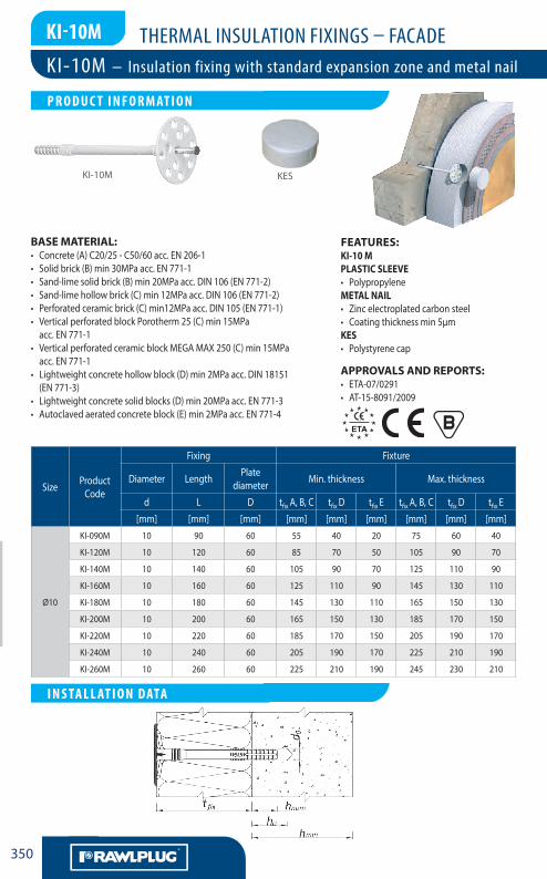
KI-10M – Insulation fixing with standard expansion zone and metal nail
LA CHEVILLENYLON MULTIFONCTIONS
P R O D U C T I N F O R M AT I O N
LA CHEVILLENYLON MULTIFONCTIONS
I N S TA L L AT I O N DATA
KES

THERMAL INSULATION FIXINGS – FACADE
LA CHEVILLENYLON MULTIFONCTIONS
351
F
KI-10M
1.Drillaholeofrequireddiameteranddepth.2.Lightlytaptheplasticsleevethroughtheinsulationmaterialintoholewithahammer,untilfixingdepthisreached.3.Hammerthesteelnailintotheplasticsleeveuntilfixingissecureandflushwithinsulationmaterial.
INSTALLATION GuIDE
Typeofsubstrate(acc.ETAG) A,B,C D EFixingdiameter d [mm] 10 10 10
Holediameterinsubstrate d0 [mm] 10 10 10
Min.holedepthinsubstrate h0 [mm] 35 50 70
Installationdepth hnom [mm] 25 40 60
Min.substratethickness hmin [mm] 100 100 100
Min.spacing smin [mm] 100 100 100
Min.edgedistance cmin [mm] 100 100 100
*partialsafetyfactor1.4
Substrate
Conc
reteC12
/15
Conc
rete≥C16
/20
Solid
bric
k
Sand
-limesolid
bric
k
Sand
-limeho
llowbric
k
Perfo
rated ceramicbrick
Perfo
ratedceramicbrick
(i.e.Po
rotherm)
MEG
AMAX
Lightweigh
tcon
creteho
llow
block
Lightweigh
tcon
cretesolid
blocks
Aeratedconc
rete
Embedmentdepthhef [mm] 25 25 25 25 25 40 40 40 40 60 60
MEAN uLTIMATE LOAD NRu,m
KI-10M [kN] 0.92 0.97 0.77 1.11 1.01 0.74 0.57 0.67 0.75 0.98 0.17
ChARACTERISTIC LOAD NRk
KI-10M [kN] 0.50 0.50 0.40 0.60 0.50 0.40 0.30 0.30 0.40 0.60 0.10
DESIGN LOAD NRd
KI-10M [kN] 0.25 0.25 0.20 0.30 0.25 0.20 0.15 0.15 0.20 0.30 0.05
RECOMMENDED LOAD Nrec*
KI-10M [kN] 0.18 0.18 0.14 0.21 0.18 0.14 0.11 0.11 0.14 0.21 0.04
Fixingtype KI-10MPlateresistance [kN] 0.86
Platestiffness [kN/mm] 0.6
Pointthermaltransmittanceλ [W/K] –
Performancedataforsingleanchorintensionwithoutinfluenceofedgedistanceandspacing
LA CHEVILLENYLON MULTIFONCTIONS
B A S I C P E R F O R M A N C E DATA

THERMAL INSULATION FIXINGS – FACADE
LA CHEVILLENYLON MULTIFONCTIONS
AA352
F
KI-10N
BASE MATERIAL:• Solidbrick(B)min20MPaacc.EN771-1• Verticallyperforatedblocks(C)acc.PN-B-12069:1998• Lightweightaggregateconcretehollowblocks(D)10MPaacc.EN771-3
• Autoclavedaeratedconcreteblocks(E)600markVacc.EN771-4
Size ProductCode
Fixing Fixture
Diameter Length Platediameter Min.thickness Max.thickness
d L D tfixB,C,D,E tfixB,C,D,E
[mm] [mm] [mm] [mm] [mm]
Ø10
KI-120N 10 120 60 50 70
KI-140N 10 140 60 70 90
KI-160N 10 160 60 90 110
KI-180N 10 180 60 110 130
KI-200N 10 200 60 130 150
KI-220N 10 220 60 150 170
KI-240N 10 240 60 170 190
KI-260N 10 260 60 190 210
KI-300N 10 300 60 210 250
FEATuRES:PLASTIC SLEEVE• PolypropyleneSTEEL NAIL• Zincelectroplatedcarbonsteel• Coatingthicknessmin5µm• Nylonheadpiece
APPROVALS AND REPORTS:• ETA-07/0221
KI-10N
KI-10N – Insulation fixing with long expansion zone
LA CHEVILLENYLON MULTIFONCTIONS
P R O D U C T I N F O R M AT I O N
LA CHEVILLENYLON MULTIFONCTIONS
I N S TA L L AT I O N DATA

THERMAL INSULATION FIXINGS – FACADE
LA CHEVILLENYLON MULTIFONCTIONS
353
F
KI-10N
1.Drillaholeofrequireddiameteranddepth.2.Lightlytaptheplasticsleevethroughtheinsulationmaterialintoholewithahammer,untilfixingdepthisreached.3.Hammerthenailintotheplasticsleeveuntilfixingissecureandflushwithinsulationmaterial.
INSTALLATION GuIDE
Typeofsubstrate(acc.ETAG) B,C,D,EFixingdiameter d [mm] 10
Holediameterinsubstrate d0 [mm] 10
Min.holedepthinsubstrate h0 [mm] 70
Installationdepth hnom [mm] 60
Min.substratethickness hmin [mm] 100
Min.spacing smin [mm] 100
Min.edgedistance cmin [mm] 100
Performancedataforsingleanchorintensionwithoutinfluenceofedgedistanceandspacing
*partialsafetyfactor1.4
Substrate Solidbrick Verticallyperforatedblocks
Lightweightaggregateconcrete
hollowblocks
Autoclavedaeratedconcreteblocks
Embedmentdepthhef [mm] 60 60 60 60
MEAN uLTIMATE LOAD NRu,m
KI-10N [kN] 1.57 0.82 0.88 1.54
ChARACTERISTIC LOAD NRk
KI-10N [kN] 0.90 0.40 0.30 0.90
DESIGN LOAD NRd
KI-10N [kN] 0.45 0.20 0.15 0.45
RECOMMENDED LOAD Nrec*
KI-10N [kN] 0.32 0.14 0.11 0.32
Fixingtype KI-10NPlateresistance [kN] 1.04
Platestiffness [kN/mm] 0.50
Pointthermaltransmittanceλ [W/K] –
DANE uPROSzCzONE DLA POjEDyNCzEGO zAMOCOwANIA
LA CHEVILLENYLON MULTIFONCTIONS
B A S I C P E R F O R M A N C E DATA

THERMAL INSULATION FIXINGS – FACADE
LA CHEVILLENYLON MULTIFONCTIONS
AA354
F
BASE MATERIAL:• Solidbrick(B)min20MPaacc.EN771-1• Verticallyperforatedblocks(C)acc.PN-B-12069:1998
• Lightweightaggregateconcretehollowblocks(D)10MPaacc.EN771-3
• Autoclavedaeratedconcreteblocks(E)600markVacc.EN771-4
FEATuRES:PLASTIC SLEEVE• PolypropyleneSTEEL NAIL• Zincelectroplatedcarbonsteel• Coatingthicknessmin5µm• Nylonheadpiecewithhexdrive
APPROVALS AND REPORTS:• ETA-07/0221
KI-10NS
Size ProductCode
Fixing Fixture
Diameter Length Platediameter Min.thickness Max.thickness
d L D tfixB,C,D,E tfixB,C,D,E
[mm] [mm] [mm] [mm] [mm]
Ø10
KI-120NS 10 120 60 50 70
KI-140NS 10 140 60 70 90
KI-160NS 10 160 60 90 110
KI-180NS 10 180 60 110 130
KI-200NS 10 200 60 130 150
KI-220NS 10 220 60 150 170
KI-260NS 10 260 60 190 210
KI-300NS 10 300 60 230 250
KI-10NS – Insulation fixing with long expansion zone and screw
LA CHEVILLENYLON MULTIFONCTIONS
P R O D U C T I N F O R M AT I O N
KI-10NS
LA CHEVILLENYLON MULTIFONCTIONS
I N S TA L L AT I O N DATA

THERMAL INSULATION FIXINGS – FACADE
LA CHEVILLENYLON MULTIFONCTIONS
355
F
1.Drillaholeofrequireddiameteranddepth.2.Lightlytaptheplasticsleevethroughtheinsulationmaterialintoholewithahammer,untilfixingdepthisreached.3.Tightenscrewuntilfixingissecureandflushwithinsulationmaterial.
INSTALLATION GuIDE
Typeofsubstrate(acc.ETAG) B,C,D,EFixingdiameter d [mm] 10
Holediameterinsubstrate d0 [mm] 10
Min.holedepthinsubstrate h0 [mm] 70
Installationdepth hnom [mm] 60
Min.substratethickness hmin [mm] 100
Min.spacing smin [mm] 100
Min.edgedistance cmin [mm] 100
*partialsafetyfactor1.4
Substrate Solidbrick Verticallyperforatedblocks
Lightweightaggregateconcrete
hollowblocks
Autoclavedaeratedconcreteblocks
Embedmentdepthhef [mm] 60 60 60 60
MEAN uLTIMATE LOAD NRu,m
KI-10NS [kN] 1.86 0.71 0.53 0.89
ChARACTERISTIC LOAD NRk
KI-10NS [kN] 1.20 0.40 0.30 0.75
DESIGN LOAD NRd
KI-10NS [kN] 0.60 0.20 0.15 0.38
RECOMMENDED LOAD Nrec*
KI-10NS [kN] 0.43 0.14 0.11 0.27
Fixingtype KI-10NPlateresistance [kN] 1.04
Platestiffness [kN/mm] 0.50
Pointthermaltransmittanceλ [W/K] –
KI-10NS
Performancedataforsingleanchorintensionwithoutinfluenceofedgedistanceandspacing
LA CHEVILLENYLON MULTIFONCTIONS
B A S I C P E R F O R M A N C E DATA

THERMAL INSULATION FIXINGS – FACADE
LA CHEVILLENYLON MULTIFONCTIONS
AA356
F
MKI+MKC
BASE MATERIAL:• Concrete(A)minC20/25acc.PN-EN206-1:2003• Claybrick(B)min15MPaacc.PN-EN771-1:2006• Sand-limesolidbrick(B)min15MPaacc.PN-EN771-2:2006
• Aeratedconcrete(E)600MarkVacc.PN-EN771-4:2004
Size ProductCode
Fixing Fixture
Diameter Length PlatediameterMKC Max.thickness
d L D tfix
[mm] [mm] [mm] [mm]
Ø8
MKI-060/8 8 60 80 10
MKI-090/8 8 90 80 40
MKI-110/8 8 110 80 60
MKI-130/8 8 130 80 80
MKI-140/8 8 140 80 90
MKI-150/8 8 150 80 100
MKI-170/8 8 170 80 120
MKI-190/8 8 190 80 140
MKI-200/8 8 200 80 150
MKI-210/8 8 210 80 160
MKI-230/8 8 230 80 180
MKI-250/8 8 250 80 200
MKI-270/8 8 270 80 220
MKI-300/8 8 300 80 250
FEATuRES:OnthebasisofEuropeanComissionDecisionNo.96/603/EC,2000/605/ECand2003/424/ECKOELNERMKIsteelconnectorsareclassifiedinClassA1ofreactiontofire,andonthebasisofinstruc-tionsITBNo401/2004havebeenclassifiedasnon-combustible.FIXING:• Carbonsteel,gradeS235JRG2• Coatingthicknessmin8µm
APPROVALS AND REPORTS:• AT-15-8092/2009
MKI MKC
MKI+MKC – Fireproof connector for EPS and mineral wool installation
LA CHEVILLENYLON MULTIFONCTIONS
P R O D U C T I N F O R M AT I O N
LA CHEVILLENYLON MULTIFONCTIONS
I N S TA L L AT I O N DATA

THERMAL INSULATION FIXINGS – FACADE
LA CHEVILLENYLON MULTIFONCTIONS
357
F
MKI+MKC
Substrate A,B EFixingdiameter d [mm] 8 8
Holediameterinsubstrate d0 [mm] 8 -
Min.holedepthinsubstrate h0 [mm] 60 -
Installationdepth hnom [mm] 50 50
Min.substratethickness hmin [mm] 100 100
Min.spacing smin [mm] 100 100
Min.edgedistance cmin [mm] 100 100
Performancedataforsingleanchorintensionwithoutinfluenceofedgedistanceandspacing
*partialsafetyfactor1.4
Substrate Concrete Solidbrick Sand-limesolidbrick Autoclavedaeratedconcrete
Embedmentdepthhhef [mm] 50 50 50 50
MEAN uLTIMATE LOAD NRu,m
MKI+MKC [kN] 1.05 0.85 0.85 1.05
ChARACTERISTIC LOAD NRk
MKI+MKC [kN] 0.85 0.65 0.80 0.90
DESIGN LOAD NRd
MKI+MKC [kN] 0.34 0.22 0.32 0.26
RECOMMENDED LOAD Nrec*
MKI+MKC [kN] 0.24 0.16 0.23 0.19
Fixingtype MKI+MKC-80Pullthefixingplatethroughtheinsulationmaterialwiththickness50mm.Acc.ETAG004 [kN] 0.32*
*characteristicload
1.Drillaholeofrequireddiameteranddepth.2.LightlytapMKIfixing,withMKCwasher,throughtheinsulationmaterialintoholewithahammer,untilfixingdepthisreached.
INSTALLATION GuIDE
LA CHEVILLENYLON MULTIFONCTIONS
B A S I C P E R F O R M A N C E DATA
THERMAL INSULATION FIXINGS – FACADE
LA CHEVILLENYLON MULTIFONCTIONS
AA358
F
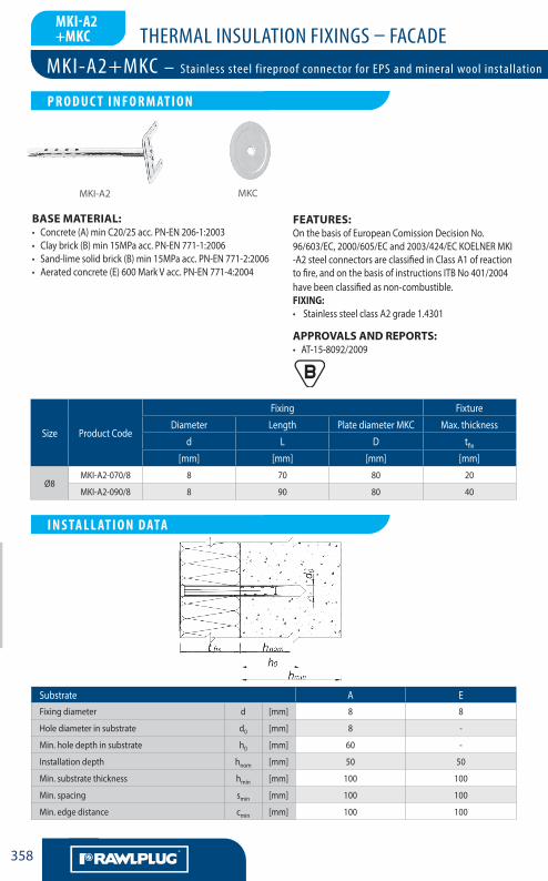
MKI-A2+MKC
BASE MATERIAL:• Concrete(A)minC20/25acc.PN-EN206-1:2003• Claybrick(B)min15MPaacc.PN-EN771-1:2006• Sand-limesolidbrick(B)min15MPaacc.PN-EN771-2:2006• Aeratedconcrete(E)600MarkVacc.PN-EN771-4:2004
Size ProductCode
Fixing Fixture
Diameter Length PlatediameterMKC Max.thickness
d L D tfix
[mm] [mm] [mm] [mm]
Ø8MKI-A2-070/8 8 70 80 20
MKI-A2-090/8 8 90 80 40
FEATuRES:OnthebasisofEuropeanComissionDecisionNo.96/603/EC,2000/605/ECand2003/424/ECKOELNERMKI-A2steelconnectorsareclassifiedinClassA1ofreactiontofire,andonthebasisofinstructionsITBNo401/2004havebeenclassifiedasnon-combustible.FIXING:• StainlesssteelclassA2grade1.4301
APPROVALS AND REPORTS:• AT-15-8092/2009
MKC
Substrate A EFixingdiameter d [mm] 8 8
Holediameterinsubstrate d0 [mm] 8 -
Min.holedepthinsubstrate h0 [mm] 60 -
Installationdepth hnom [mm] 50 50
Min.substratethickness hmin [mm] 100 100
Min.spacing smin [mm] 100 100
Min.edgedistance cmin [mm] 100 100
MKI-A2+MKC – Stainless steel fireproof connector for EPS and mineral wool installation
LA CHEVILLENYLON MULTIFONCTIONS
P R O D U C T I N F O R M AT I O N
LA CHEVILLENYLON MULTIFONCTIONS
I N S TA L L AT I O N DATA
MKI-A2
THERMAL INSULATION FIXINGS – FACADE
LA CHEVILLENYLON MULTIFONCTIONS
359
F
Performance data for single anchor in tension without influence of edge distance and spacing
* partial safety factor 1.4
Substrate Concrete Solid brick Sand-lime solid brick Autoclaved aerated concrete
Embedment depth hef [mm] 50 50 50 50
Mean ultiMate load nRu,m
MKI-A2 + MKC [kN] 1.10 0.85 0.90 1.10
ChaRaCteRistiC load nRk
MKI-A2 + MKC [kN] 0.95 0.75 0.85 0.90
design load nRd
MKI-A2 + MKC [kN] 0.37 0.26 0.30 0.29
ReCoMMended load nrec*
MKI-A2 + MKC [kN] 0.26 0.19 0.21 0.21
Fixing type MKI-A2+MKC-80Pull the fixing plate through the insulation material with thickness 50 mm. Acc. ETAG 004 [kN] 0.32*
* characteristic load
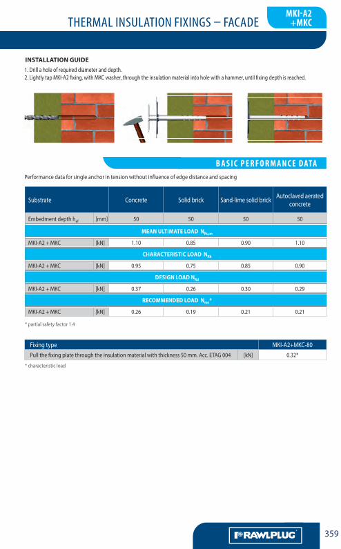
installation guide1. Drill a hole of required diameter and depth.2. Lightly tap MKI-A2 fixing, with MKC washer, through the insulation material into hole with a hammer, until fixing depth is reached.
MKI-A2+MKC – Stainless steel fireproof connector for EPS and mineral wool installation
mki-a2+mkc
LA CHEVILLENYLON MULTIFONCTIONS
B a S i c P E R F O R m a N c E DaTa
THERMAL INSULATION FIXINGS – FACADE
LA CHEVILLENYLON MULTIFONCTIONS
AA360
F
kc+Uc
Base MateRial:• Timber class C24 acc. PN-EN 338:2004
Size Product Code
Fixing Fixture
ScrewPlate diameter Max. thickness
Diameter Length
d L D tfix
[mm] [mm] [mm] [mm]
Ø5.0
KC + UC-5050 5 50 60 30
KC + UC-5060 5 60 60 40
KC + UC-5070 5 70 60 50
KC + UC-5080 5 80 60 60
KC + UC-5090 5 90 60 70
KC + UC-50100 5 100 60 80
Ø6.0
KC + UC-60100 6 100 60 75
KC + UC-60120 6 120 60 95
KC + UC-60140 6 140 60 115
KC + UC-60160 6 160 60 135
KC + UC-60200 6 200 60 175
FeatuRes:Flange• Impact resistant polypropylene PP copolymersCReW• Zinc electroplated carbon steel• Coating thickness min 5µm
aPPRoVals and RePoRts:• AT-15-4627/2012
KC + UC
Substrate TimberFixing diameter d [mm] 5 6
Hole diameter in substrate d0 [mm] – –
Min. hole depth in substrate h0 [mm] – –
Installation depth hnom [mm] 20 25
Min. substrate thickness hmin [mm] 20 25
Min. spacing smin [mm] 100 100
Min. edge distance cmin [mm] 100 100
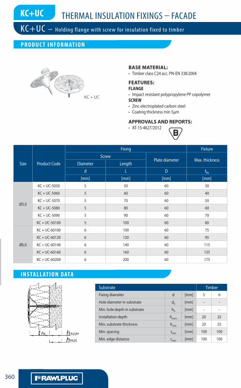
KC+UC – Holding flange with screw for insulation fixed to timber
LA CHEVILLENYLON MULTIFONCTIONS
P R O D U c T i N F O R m aT i O N
LA CHEVILLENYLON MULTIFONCTIONS
i N S Ta L L aT i O N DaTa

THERMAL INSULATION FIXINGS – FACADE
LA CHEVILLENYLON MULTIFONCTIONS
361
F
1. Lightly insert KC plate into insulation material and drill the UC screw into substrate, until fixing depth is reached.
installation guide
Performance data for single anchor in tension without influence of edge distance and spacing
* partial safety factor 1.4screw pulls through flange
Substrate Timber
Embedment depth hef [mm] 20 25
Mean ultiMate load nRu,m
KC+UC Ø5.0 [kN] 0.78 –
KC+UC Ø6.0 [kN] – 0.98
ChaRaCteRistiC load nRk
KC+UC Ø5.0 [kN] 0.73 –
KC+UC Ø6.0 [kN] – 0.91
design load nRd
KC+UC Ø5.0 [kN] 0.24 –
KC+UC Ø6.0 [kN] – 0.30
ReCoMMended load nrec*
KC+UC Ø5.0 [kN] 0.17 –
KC+UC Ø6.0 [kN] – 0.22
KC+UC – Holding flange with screw for insulation fixed to timber
kc+Uc
LA CHEVILLENYLON MULTIFONCTIONS
B a S i c P E R F O R m a N c E DaTa

THERMAL INSULATION FIXINGS – FACADE
LA CHEVILLENYLON MULTIFONCTIONS
AA362
F
kc+WB
Base MateRial:• Steel 0.75-2.00mm thickness, grade S280GD
acc. PN-EN 10346:2011
Size Product Code
Fixing Fixture
ScrewPlate diameter Max. thickness
Diameter Length
d L D tfix
[mm] [mm] [mm] [mm]
Ø5.0
KC + WB-48100 4.8 100 60 90
KC + WB-48120 4.8 120 60 110
KC + WB-48140 4.8 140 60 130
KC + WB-48160 4.8 160 60 150
KC + WB-48170* 4.8 170 60 160
KC + WB-48180 4.8 180 60 170
KC + WB-48200 4.8 200 60 190
KC + WB-48220 4.8 220 60 210
FeatuRes:Flange• Impact-resistant polypropylene PP copolymersCReW• Zinc electroplated carbon steel • Coating thickness min 5µm• Self-tapping
aPPRoVals and RePoRts:• AT-15-4627/2012
KC + UC
Substrate SteelFixing diameter d [mm] 4.8
Hole diameter in substrate d0 [mm] –
Min. hole depth in substrate h0 [mm] –
Installation depth hnom [mm] 0.75
Min. substrate thickness hmin [mm] 0.75
Min. spacing smin [mm] 100
Min. edge distance cmin [mm] 100
KC+WB – Holding flange with screw for insulation fixed to steel
LA CHEVILLENYLON MULTIFONCTIONS
P R O D U c T i N F O R m aT i O N
LA CHEVILLENYLON MULTIFONCTIONS
i N S Ta L L aT i O N DaTa
LA CHEVILLENYLON MULTIFONCTIONS
P R O D U c T i N F O R m aT i O N
* not covered by approval

THERMAL INSULATION FIXINGS – FACADE
LA CHEVILLENYLON MULTIFONCTIONS
363
F
installation guide
Performance data for single anchor in tension without influence of edge distance and spacing
* partial safety factor 1.4
Substrate Steel
Embedment depth hef [mm] 0.75
Mean ultiMate load nRu,m
KC + WB [kN] 0.86
ChaRaCteRistiC load nRk
KC + WB [kN] 0.81
design load nRd
KC + WB [kN] 0.44
ReCoMMended load nrec*
KC + WB [kN] 0.31
1. Lightly insert KC plate into insulation material and drill the WB screw into substrate, until fixing depth is reached.
KC+WB – Holding flange with screw for insulation fixed to steel
LA CHEVILLENYLON MULTIFONCTIONS
B a S i c P E R F O R m a N c E DaTa
kc+WB

THERMAL INSULATION FIXINGS – FACADE
LA CHEVILLENYLON MULTIFONCTIONS
AA364
F
kik
Base MateRial:• Concrete• Solid brick
FeatuRes:FiXing• Impact-resistant polypropylene copolymer
Size Ø8Fixing diameter d [mm] 8
Hole diameter in substrate d0 [mm] 8
Min. hole depth in substrate h0 [mm] 40
Installation depth hnom [mm] 30
Min. substrate thickness hmin [mm] 100
Min. spacing smin [mm] 100
Min. edge distance cmin [mm] 100
Size Product Code
Fixing Fixture
Diameter Length Plate diameter Max. thickness
d L D tfix
[mm] [mm] [mm] [mm]
Ø10KIK-070 8 70 35 30
KIK-090 8 90 35 50
KIK
1. Drill a hole of required diameter and depth.2. Lightly tap the plastic fixing through the insulation material into hole with a hammer, until fixing depth is reached.
installation guide
KIK – Single fixing for insulation installed in zones without wind forces KWL – Insulation holding flange for KI, TFIX & KC fixings
LA CHEVILLENYLON MULTIFONCTIONS
P R O D U c T i N F O R m aT i O N
LA CHEVILLENYLON MULTIFONCTIONS
i N S Ta L L aT i O N DaTa

THERMAL INSULATION FIXINGS – FACADE
LA CHEVILLENYLON MULTIFONCTIONS
365
F
kWL
FeatuRes:used in ConJunCtion With tFiX, Ki, KC• Polyamide PA 6.0 reinforced with fibre glass • Impact resistant copolymer of polypropylene PP • Installations of lamella wool to substrate
aPPRoVals and RePoRts:• ETA-07/0221 • ETA-07/0291 • ETA-07/0336 • ETA-11/0144 • AT-15-4627/2012
1. Drill a hole of required diameter and depth.2. Lightly tap the plastic sleeve with additional KWL flange through the insulation material into hole with a hammer, until fixing depth is reached.3. Lightly hammer the nail into the plastic sleeve (or tighten screw) until fixing is secure and flush with insulation material.
installation guide
Size Product Code
Fixing
Diameter Length Plate diameter
d L D
[mm] [mm] [mm]Ø90 KWL-090 90 − 60
Ø110 KWL-110 110 − 60
Ø120 KWL-140 140 − 60
KWL-140
KWL-110KWL-090
KIK – Single fixing for insulation installed in zones without wind forces KWL – Insulation holding flange for KI, TFIX & KC fixings
LA CHEVILLENYLON MULTIFONCTIONS
P R O D U c T i N F O R m aT i O N
LA CHEVILLENYLON MULTIFONCTIONS
i N S Ta L L aT i O N DaTa

THERMAL INSULATION FIXINGS – FACADE
LA CHEVILLENYLON MULTIFONCTIONS
AA366
F
NOTES