technical guidelines - ardex americas · pdf fileabout icri guidelines ... 506r-05,...
TRANSCRIPT

TECHNICAL
GUIDELINESPrepared by the International Concrete Repair Institute December 2008
Guideline No. 310.1R–2008 (formerly No. 03730)Copyright © 2008 International Concrete Repair Institute
Guide for Surface Preparation for the Repair of Deteriorated Concrete Resulting from Reinforcing Steel Corrosion


Copyright © 2008 International Concrete Repair Institute
All rights reserved.
International Concrete Repair Institute 3166 S. River Road, Suite 132, Des Plaines, IL 60018Phone: 847-827-0830 Fax: 847-827-0832Web site: www.icri.orgE-mail: [email protected]
TECHNICAL
GUIDELINES
Guideline No. 310.1R–2008 (formerly No. 03730)
Guide for Surface Preparation for the Repair of Deteriorated Concrete Resulting from Reinforcing Steel Corrosion
Prepared by the International Concrete Repair Institute December 2008

GuIDe foR SuRfaCe PRePaRatIon foR the RePaIR of DeteRIoRateD ConCRete ReSultInG fRom ReInfoRCInG Steel CoRRoSIon310.1R–2008
About ICRI GuidelinesThe International Concrete Repair Institute (ICRI) was founded to improve the durability of concrete repair and enhance its value for structure owners. The identification, development, and promotion of the most promising methods and materials are primary vehicles for accelerating advances in repair technology. Working through a variety of forums, ICRI members have the opportunity to address these issues and to directly contribute to improving the practice of concrete repair.
A principal component of this effort is to make carefully selected information on important repair subjects readily accessible to decision makers. During the past several decades, much has been reported in the literature on concrete repair methods and materials as they have been developed and refined. Nevertheless, it has been difficult to find critically reviewed information on the state of the art condensed into easy-to-use formats.
To that end, ICRI guidelines are prepared by sanctioned task groups and approved by the ICRI Technical Activities Committee. Each guideline is designed to address a specific area of practice recognized as essential to the achievement of durable repairs. All ICRI guideline documents are subject to continual review by the membership and may be revised as approved by the Technical Activities Committee.
Producers of this GuidelineSurface Preparation Committee
Pat Winkler, Chair*Dan AnagnosRandy BeardBruce Collins
William “Bud” Earley Peter Emmons*
Andrew FulkersonRandy Glover
Fred Goodwin*Kurt GottingerTyson Herman
Dave HomerdingBob JohnsonDavid KarinsKen Lozen*
Jim McDonaldBeth NewboldJeffery Smith
Sandra SproutsRick Toman
Patrick Watson
*Contributing editors
Technical Activities CommitteeKevin Michols, Chair
Jim McDonald, SecretaryRandy BeardDon Caple
Bruce CollinsWilliam “Bud” Earley
Don FordTim GillespiePeter Golter
Peter LipphardtDavid Rodler
Michael TabassiDavid Whitmore
Pat Winkler
SynopsisThis guideline provides guidance on concrete removal and surface preparation procedures for the repair of deteriorated concrete caused by reinforcing steel corrosion. Removal geometry, configuration of the repair area, removal process, edge preparation, reinforcement repair, surface preparation and inspection necessary for durable repairs are discussed. Special considerations for concrete removal associated with column repair are included.
Keywordsanodic ring effect, bonding, bruising, corrosion, delamination, deterioration, reinforcing steel, structural repair, surface preparation.
This document is intended as a voluntary guideline for the owner, design professional, and concrete repair contractor. It is not intended to relieve the professional engineer or designer of any responsibility for the specification of concrete repair methods, materials, or practices. While we believe the information contained herein represents the proper means to achieve quality results, the International Concrete Repair Institute must disclaim any liability or responsibility to those who may choose to rely on all or any part of this guideline.
GuIDe foR SuRfaCe PRePaRatIon foR the RePaIR of DeteRIoRateD ConCRete ReSultInG fRom ReInfoRCInG Steel CoRRoSIon 310.1R–2008
Contents
1.0 Introduction ..............................................................................................................................1 2.0 Definitions ...............................................................................................................................1 3.0 Exposure of Reinforcing Steel ..................................................................................................1 4.0 Anodic Ring (Halo) Effect .........................................................................................................2 5.0 Removal Geometry .................................................................................................................2 6.0 Configuration of Repair Area ...................................................................................................3 7.0 Concrete Removal/Surface Preparation ...................................................................................3 7.1 exposing and undercutting of Reinforcing Steel ..................................................................3 7.2 Preparation of the Repair Perimeter ....................................................................................4 7.3 Cleaning of the Concrete Surface and Reinforcing Steel .....................................................4 8.0 Inspection and Repair of Reinforcing Steel .............................................................................5 9.0 Final Surface Inspection .........................................................................................................5 10.0 Special Conditions at Columns ................................................................................................6 11.0 Summary ................................................................................................................................7 12.0 References ...............................................................................................................................7 12.1 Referenced Standards and Reports ....................................................................................7
GuIDe foR SuRfaCe PRePaRatIon foR the RePaIR of DeteRIoRateD ConCRete ReSultInG fRom ReInfoRCInG Steel CoRRoSIon310.1R–2008

310.1R–2008 - 1GuIDe foR SuRfaCe PRePaRatIon foR the RePaIR of DeteRIoRateD ConCRete ReSultInG fRom ReInfoRCInG Steel CoRRoSIon
1.0 IntroductionThis guideline provides owners, design profes-sionals, contractors, and other interested parties with a recommended practice for the removal of deteriorated concrete caused by the corrosion of reinforcing steel, including the preparation of the removal cavity to provide a clean sound surface to bond a repair material.
This guideline outlines removal geometry, configuration, removal process, edge preparation, reinforcement repair, surface preparation, and inspection prior to placing a repair material. An engineer should evaluate the impact of concrete removal on structural capacity prior to performing concrete removal and repair. The repair methods involve saw cutting and concrete removal using impact tools, hydrodemolition, and other removal techniques. Special caution should be taken to locate and avoid cutting or damaging embedded reinforcing bars, prestressing strands, post-tensioning tendons, or electrical conduits. Cutting into these items can be life threatening and may significantly affect structural integrity.
This guideline also contains a discussion of concrete removal and preparation for the repair of columns where the concrete is in compression. Special consideration must be given to the repair of concrete in compression as the load-carrying capacity of the element may be permanently compromised during the concrete removal and preparation process.
While the procedures outlined herein have been used to successfully remove concrete and prepare the removal cavity on many projects, the requirements for each project will vary due to many different factors. Each project should be evaluated individually to ascertain the applicability of the procedures described herein. Refer to ACI 506R-05, “Guide to Shotcrete” for surface prepar-ation prior to shotcrete application.
2.0 DefinitionsAnodic ring effect: Corrosion process in which
the steel reinforcement in the concrete surrounding a repaired area begins to corrode preferentially to the steel reinforcement in the newly repaired area (sometimes referred to as the halo effect).
Bruised surface (micro-fracturing): A surface layer weakened by interconnected microcracks in concrete substrates caused by the use of high-impact, mechanical methods for concrete removal, and surface preparation; fractured layer
typically extends to a depth of 0.13 to 0.38 in. (3 to 10 mm) and, if not removed, frequently results in lower bond strengths as compared with surfaces prepared with nonimpact methods.
Carbonation: The conversion of calcium ions in hardened cementitious materials to calcium carbonate by reaction with atmospheric carbon dioxide. Carbonation reduces the pH of the concrete and its ability to protect reinforcing steel and embedded metal items from corrosion.
Chloride contamination: Contamination of concrete with chloride ions commonly used in deicing salts and accelerating admixtures such as calcium chloride and sodium chloride. Chloride contamination above the threshold for corrosion can result in corrosion of the reinforcing steel.
Chloride threshold: The amount of chloride required to initiate steel corrosion in reinforced concrete under a given set of exposure conditions; commonly expressed in percent of chloride ion by mass of cement.
Corrosion: Degradation of concrete or steel reinforcement caused by electrochemical or chemical attack.
Microcrack: A crack too small to be seen with the unaided eye.
Tensile pulloff test: A test to determine the unit stress, applied in direct tension, required to separate a hardened repair material from the existing concrete substrate. The test may also be used to determine the maximum unit stress that the existing concrete substrate is capable of resisting under axial tensile loading and the near-surface tensile strength of a prepared surface (refer to ICRI Technical Guideline No. 210.3–2004 [formerly No. 03739] and ASTM C1583).
Substrate: The layer immediately under a layer of different material to which it is typically bonded; an existing concrete surface that receives an overlay, partial-depth repair, protective coating, or some other maintenance or repair procedure.
3.0 Exposure of Reinforcing SteelThe practice of completely removing the concrete (undercutting) from around the corroded reinforcement, no matter what degree of corrosion is found, is key to achieving long-term performance of surface repairs. In most cases, complete removal of the concrete from around the reinforcing steel is the best practice, where protection of the reinforcing steel within the

GuIDe foR SuRfaCe PRePaRatIon foR the RePaIR of DeteRIoRateD ConCRete ReSultInG fRom ReInfoRCInG Steel CoRRoSIon2 - 310.1R–2008
repair cavity is achieved by providing a uniform chemical environment around the reinforcing steel. If noncorroded reinforcing steel is exposed and the concrete is chloride contaminated, removal of the concrete around the reinforcing should occur or other corrosion-reducing means should be considered. Reinforcing steel partially embedded in chloride-contaminated concrete is susceptible to future accelerated corrosion.
If, for structural reasons, the concrete cannot be completely removed from around the corroded reinforcing steel or if a corrosion inhibiting system is not used, the repair may be compromised due to continued corrosion. If there is a potential trade-off between durability and structural capacity, structural capacity should always take priority. When reinforcing steel is not fully exposed through the concrete removal and preparation process, alternative corrosion inhib-iting systems should be considered. These systems may include use of corrosion inhibitors, sacrificial anodes, or cathodic protection.
4.0 Anodic Ring (Halo) Effect The existing concrete surrounding a repair area in chloride-contaminated or low pH reinforced concrete is susceptible to accelerated corrosion. This is due to the electrical potential differential between the chloride contaminated or low pH existing concrete and the chloride-free or high pH repair material. This anodic ring effect
can result in accelerated corrosion of the surrounding reinforcing steel leading to future concrete deterioration. To assess existing concrete conditions beyond the repair area, chloride content and pH of the concrete at the level of the reinforcing steel should be determined. Where the chloride content exceeds the threshold level for the initiation of corrosion or where the reinforcing steel is susceptible to corrosion as a result of carbonation, a corrosion inhibiting system should be considered to minimize future corrosion. Other measures may also be considered, such as the application of sealers and coatings, to slow the corrosion process. In severely chloride-contaminated or carbonated concrete, the complete removal and replacement of the contaminated concrete at and beyond the repair area may be necessary to provide a successful long-term repair.
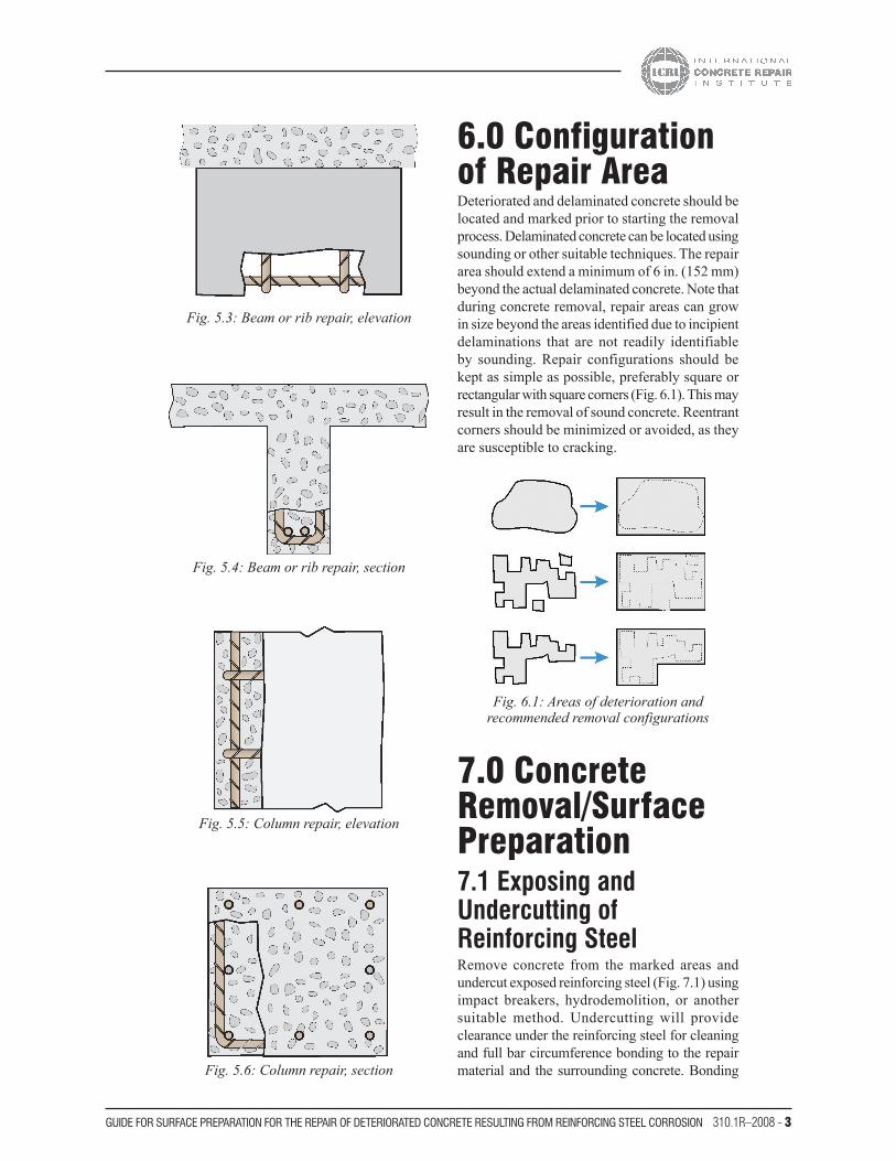
5.0 Removal GeometryExamples of the removal geometry for several different types of reinforced concrete elements are shown in Fig. 5.1 through 5.6. Repairs may be located on horizontal, vertical, and/or overhead surfaces. The removal in Fig. 5.5 and 5.6 is for columns where the removal will not affect the structural capacity of the column. Removal of concrete within the reinforcing or to expose the reinforcing (concrete in compression) is a special condition and is discussed in Section 10.
Fig. 5.1: Partial depth repair, slab or wall, section
Fig. 5.2: Full depth repair, slab or wall, section
310.1R–2008 - 3GuIDe foR SuRfaCe PRePaRatIon foR the RePaIR of DeteRIoRateD ConCRete ReSultInG fRom ReInfoRCInG Steel CoRRoSIon
6.0 Configuration of Repair AreaDeteriorated and delaminated concrete should be located and marked prior to starting the removal process. Delaminated concrete can be located using sounding or other suitable techniques. The repair area should extend a minimum of 6 in. (152 mm) beyond the actual delaminated concrete. Note that during concrete removal, repair areas can grow in size beyond the areas identified due to incipient delaminations that are not readily identifiable by sounding. Repair configurations should be kept as simple as possible, preferably square or rectangular with square corners (Fig. 6.1). This may result in the removal of sound concrete. Reentrant corners should be minimized or avoided, as they are susceptible to cracking.
Fig. 5.3: Beam or rib repair, elevation
Fig. 5.4: Beam or rib repair, section
Fig. 5.5: Column repair, elevation
Fig. 5.6: Column repair, section
Fig. 6.1: Areas of deterioration and recommended removal configurations
7.0 Concrete Removal/Surface Preparation7.1 Exposing and Undercutting of Reinforcing SteelRemove concrete from the marked areas and undercut exposed reinforcing steel (Fig. 7.1) using impact breakers, hydrodemolition, or another suitable method. Undercutting will provide clearance under the reinforcing steel for cleaning and full bar circumference bonding to the repair material and the surrounding concrete. Bonding

GuIDe foR SuRfaCe PRePaRatIon foR the RePaIR of DeteRIoRateD ConCRete ReSultInG fRom ReInfoRCInG Steel CoRRoSIon4 - 310.1R–2008
the repair material to the full circumference of the reinforcing steel will secure the repair structurally. Provide a minimum of 0.75 in. (19 mm) clearance between exposed reinforcing steel and surrounding concrete or 0.25 in. (6 mm) larger than the coarse aggregate in the repair material, whichever is greater. Sound concrete may have to be removed to provide proper clearance around the reinforcing steel. If impact breakers are used for partial depth concrete removal, the breaker should not exceed 30 lb (12 kg). A 15 lb (7 kg) breaker is preferred
to minimize damage to the substrate, reinforcing steel, and surrounding concrete.
Concrete removal should extend along the reinforcing steel until there is no further delam-ination, cracking, or significant corrosion and the reinforcing steel is well bonded to the surrounding concrete. Care should be taken to avoid significant and sudden changes in the depth of concrete removal, as the repair material is more susceptible to cracking at these locations.
If noncorroded reinforcing steel is exposed during the removal process, care should be taken to not damage the bond to the surrounding concrete. If the bond between the reinforcing steel and concrete is broken, undercutting of the reinforcing steel is required.
Remove all deteriorated concrete and additional concrete as required to provide the proper configuration and/or the minimum required thickness of repair material as required by the manufacturer of the repair material and/or the project specifications.
7.2 Preparation of the Repair PerimeterThe perimeter of the repair area should be saw cut 0.75 in. (19 mm) deep to provide a vertical edge (Fig. 7.2) for the repair material. This will avoid featheredging of the repair material. Depending on the repair material selected, the depth of the existing reinforcing and the manufacturer’s recommendations, a saw cut depth less than 0.75 in. (19 mm) deep may be sufficient. Care should be taken to avoid cutting the existing reinforcing steel.
7.3 Cleaning of the Concrete Surface and Reinforcing SteelThe use of high-impact, mechanical methods to remove deteriorated concrete will result in a surface layer weakened by interconnected micro-cracks in the concrete substrate. The fractured (bruised) layer can extend to a depth of 0.125 to 0.375 in. (3 to 10 mm) into the resultant concrete substrate and may result in reduced bond strength. Remove the bruised layer and bond-inhibiting materials such as dirt, concrete slurry, and loosely bonded concrete by oil-free abrasive blasting (Fig. 7.3) or high-pressure water blasting. The
Fig. 7.1: Remove concrete to undercut and expose reinforcing steel and
provide uniform repair depth
Fig. 7.2: Saw cut perimeter to provide vertical edge
Fig. 7.3: Abrasive blasting to clean substrate and reinforcing
310.1R–2008 - 5GuIDe foR SuRfaCe PRePaRatIon foR the RePaIR of DeteRIoRateD ConCRete ReSultInG fRom ReInfoRCInG Steel CoRRoSIon
saw-cut edge of the repair area should also be blasted to roughen the polished vertical surface caused by the saw-cutting.
All concrete, corrosion products, and scale should be removed from the reinforcing steel by oil-free abrasive blasting or high-pressure water blasting. Verify that the reinforcing steel and concrete surface are free from dirt, oil, cement fines (slurry), or any material that may interfere with the bond of the repair material. Inspect the repair cavity to verify that all delaminations and deterioration have been removed. If hydro-demolition is used, cement fines (slurry) must be completely removed from the repair surface. A tightly-bonded light rust build-up on the reinforcing surface is usually not detrimental to bond. If a protective coating is applied to the reinforcing steel, follow the coating manufacturer’s recom-mendations for steel surface preparation.
8.0 Inspection and Repair of Reinforcing Steel Loose reinforcement should be secured in its original position by tying to secure bars or by other appropriate methods to prevent movement during placement of repair material.
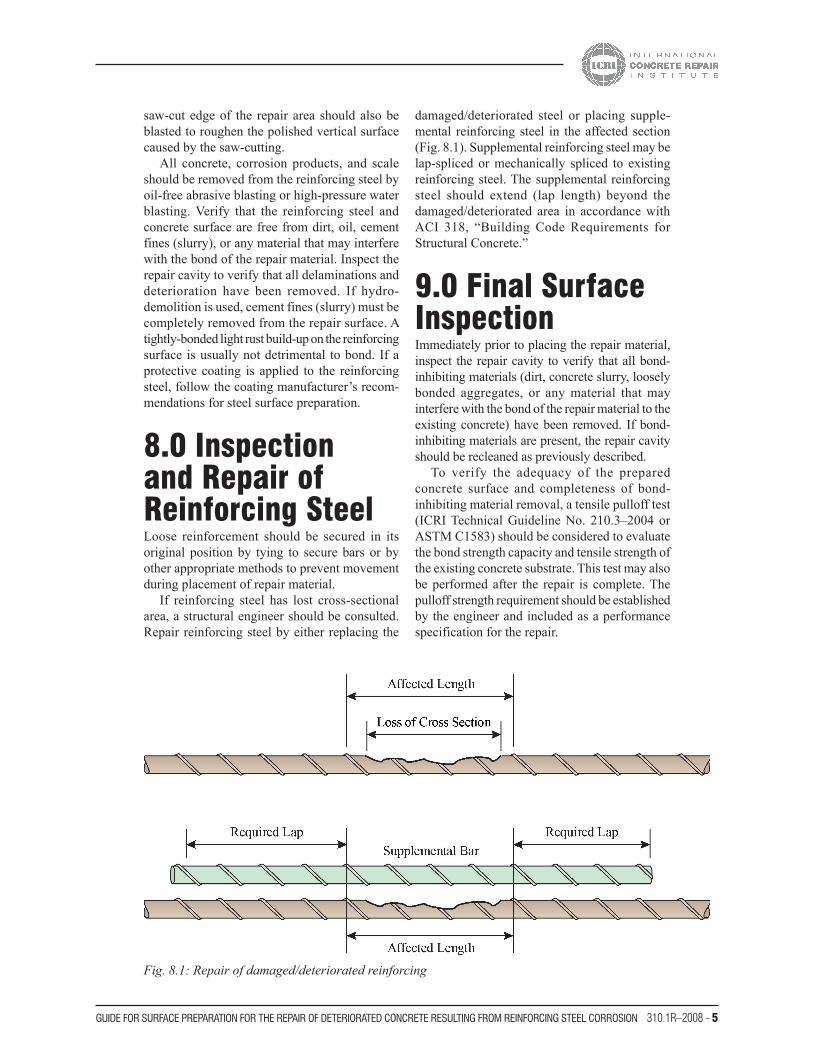
If reinforcing steel has lost cross-sectional area, a structural engineer should be consulted. Repair reinforcing steel by either replacing the
damaged/deteriorated steel or placing supple-mental reinforcing steel in the affected section (Fig. 8.1). Supplemental reinforcing steel may be lap-spliced or mechanically spliced to existing reinforcing steel. The supplemental reinforcing steel should extend (lap length) beyond the damaged/deteriorated area in accordance with ACI 318, “Building Code Requirements for Structural Concrete.”
9.0 Final Surface InspectionImmediately prior to placing the repair material, inspect the repair cavity to verify that all bond-inhibiting materials (dirt, concrete slurry, loosely bonded aggregates, or any material that may interfere with the bond of the repair material to the existing concrete) have been removed. If bond-inhibiting materials are present, the repair cavity should be recleaned as previously described.
To verify the adequacy of the prepared concrete surface and completeness of bond-inhibiting material removal, a tensile pulloff test (ICRI Technical Guideline No. 210.3–2004 or ASTM C1583) should be considered to evaluate the bond strength capacity and tensile strength of the existing concrete substrate. This test may also be performed after the repair is complete. The pulloff strength requirement should be established by the engineer and included as a performance specification for the repair.
Fig. 8.1: Repair of damaged/deteriorated reinforcing

GuIDe foR SuRfaCe PRePaRatIon foR the RePaIR of DeteRIoRateD ConCRete ReSultInG fRom ReInfoRCInG Steel CoRRoSIon6 - 310.1R–2008
10.0 Special Condition at Columns
Fig. 10.1: Column load path Fig. 10.3: Column load path following repair
Fig. 10.2b: Column section
Fig. 10.2a: Column repair

310.1R–2008 - 7GuIDe foR SuRfaCe PRePaRatIon foR the RePaIR of DeteRIoRateD ConCRete ReSultInG fRom ReInfoRCInG Steel CoRRoSIon
Undercutting of reinforcement is a best practice in tensile zones of concrete. In columns, the primary loading condition is compression. From a design perspective, the concrete section contained within the reinforcing cage is considered to carry the compressive loads (Fig. 10.1). The concrete outside of the reinforcement is considered as protective concrete cover for fire and corrosion protection of the reinforcement. Removing the concrete within the column reinforcing steel (Fig. 10.2) can greatly increase the compressive stress in the reinforcing steel and the remaining concrete. Upon concrete removal, compressive load paths redistribute around the repair (deteriorated) sections (Fig. 10.3). Depending on the size of the concrete removal area behind the column steel, buckling of the column vertical reinforcing bars can occur. In the majority of cases, shoring systems will not unload the compressive stress in the column section.
When new repair material is placed in the prepared area, the new material cures and most materials undergo drying shrinkage, which results in the new material being put into a tensile stress state. The new material will not carry compressive loads until the original concrete compresses further, forcing the repair material into compression. If further compression is beyond the capacity of the existing concrete, failure of the column may occur. This key concept affects the concrete preparation process. In normal concrete repair (other than columns), removal of the concrete surrounding the corroding reinforcement (also known as undercutting) is a normal and necessary process to provide for a long-term durable repair. To remove concrete around vertical reinforcing steel in a column (removing concrete inside the reinforcing bar cage) can cause the remaining concrete and/or reinforcement in the column to become overstressed. From a structural point of view, this condition may not be desirable. If concrete is to be removed inside the reinforcement cage, a qualified structural engineer should determine the impact of the repair on potential reinforcement buckling and overall structural capacity of the column. Note that the discussion in this section is also applicable in concept to compression zone portions of other structural members such as beams, slabs, and walls (with or without compression reinforcement) where on-going compressive stress exists and where adequate shoring cannot be installed prior to repairs to prevent displacements and corresponding stress redistributions during repairs.
11.0 SummaryThe repair of deteriorated concrete resulting from reinforcing steel corrosion is necessary to extend the service life of the structure. Performing concrete repairs using industry-best practices will ensure the success and longevity of the repair. Understanding the existing conditions and cause of corrosion will assist the engineer in specifying the type and extent of the repair required, and the type of corrosion mitigation systems and/or preventative measures that should be considered to protect the structure from future deterioration.
12.0 References12.1 Referenced Standards and Reports The following standards and reports were the latest editions at the time this document was prepared. Because these documents are revised frequently, the reader is advised to contact the proper sponsoring group if it is desired to refer to the latest version.
American Concrete Institute (ACI)ACI 506R, “Guide to Shotcrete”
ACI E706 (RAP 8), “Installation of Embedded Galvanic Anodes”
American Society for Testing and Materials (ASTM International)ASTM C1583, “Standard Test Method for Tensile Strength of Concrete Surfaces and the Bond Strength or Tensile Strength of Concrete Repair and Overlay Materials by Direct Tension (Pull- off Method)”
International Concrete Repair Institute (ICRI)ICRI Concrete Repair Terminology
ICRI Technical Guideline No. 130.1R–2008 (formerly No. 03735), “Guide for Methods of Measurement and Contract Types for Concrete Repair Work”
ICRI Technical Guideline No. 210.3-2004 (formerly No. 03739), “Guide for Using In-Situ Tensile Pull-Off Tests to Evaluate Bond of Concrete Surface Materials”

GuIDe foR SuRfaCe PRePaRatIon foR the RePaIR of DeteRIoRateD ConCRete ReSultInG fRom ReInfoRCInG Steel CoRRoSIon8 - 310.1R–2008
ICRI Technical Guideline No. 310.3–2004 (formerly No. 03737), “Guide for the Preparation of Concrete Surfaces for Repair Using Hydro-demolition Methods”
ICRI Technical Guideline No. 320.2R–2008 (formerly No. 03733), “Guide for Selecting and Specifying Materials for Repair of Concrete Surfaces”
These publications may be obtained from these organizations:American Concrete Institute38800 Country Club DriveFarmington Hills, MI 48331www.concrete.org
ASTM International100 Barr Harbor DriveWest Conshohocken, PA 19428www.astm.org
International Concrete Repair Institute3166 S. River Road, Suite 132Des Plaines, IL 60018www.icri.org


3166 S. River Road, Suite 132Des Plaines, IL 60018Phone: 847-827-0830Fax: 847-827-0832Web site: www.icri.orgE-mail: [email protected]