technical guideline structure to permanent architectures
TRANSCRIPT
VALM
EX® st
ruct
ure
Technical guideline
to permanent tensile
architectures
1st Edition
2
3
Contents
The following information is intend-ed as a basic guide for architects and engineers to assist in concept design and in specifying materials, in order to get enough preliminary background for planning activities.
Our intention is to support architects, engineers and generally all those who approach the technical and commer-cial aspects of membrane structures solutions.
General introduction 4
The Fabric – Material properties 6
Material types 7
General performances 10
Special materials application – Facades 12
Environment and sustainability 13
Design 14
Manufacture and installation 17
Maintenance 19
Frequently asked questions 21
4
Brief introduction to the tensile art of construction
Tensile architecture is probably one of the oldest methods used to provide protection from adverse climatic conditions and against predator attack. The humble ‘conic’ tent is the simplest form of tensile structure, and excelled where two conditions prevailed: a shortage of building material and a need for mobility. Evidence has been found which confirms that humans have been making tents for at least 15,000 years, initially using animal skins, and only 3000 years later, incorporating woven fabrics. One of the first appli-cations of tensile technology came at the very beginning by transferring sailing principles. The spectators at Roman amphitheatres (e.g. the Coliseum) were protected against the sun by retractable sheets of fabrics roofs, supported by timber masts and cotton fibre ropes as operated by sailors. Differing forms depended on different materials available at the time – for example the American In-dian Tepee, the Bedouin tents or the Mongolian Yurt. These forms have developed over time, using more advanced materials and construction methods into larger and more diverse structures such as the Canada Golf Dome in Beijing, China. Modern
fabric materials in modern architect-ure can shape space, enabling architects to sculpt 3-dimensional areas in a manner that is not possible with any other type of material. This kind of architecture is offering much more: the designer is able to play with light and use this for natural illumination of the space, softening it, fusing it, sharpening it or shaping it. This creates mood and ambience to reflect architectural intent, re-sulting in an energy saving covering system, by approaching the element-ary need of being in touch with nature. The dynamic shape and form of membranes allow new possibilities to become reality.
In no other sector of architecture do form and load distribution depend on each other as greatly as they do in membrane construction. Hence, these represent the perfect marriage between architecture and engineering.
As in nature, the course of forces that are shown in the form and shape can fascinate not only architects and engineers, but also the wider public as well, especially those who can appreciate the equilibrium between aesthetics and functionality.
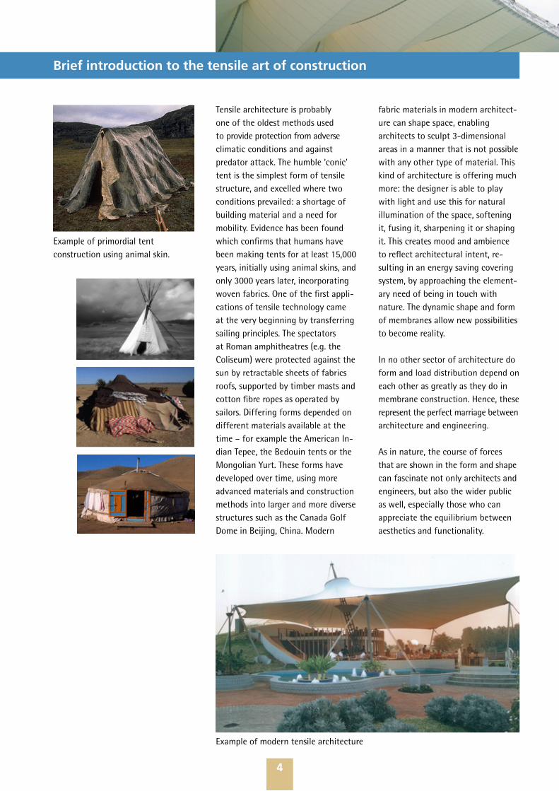
Example of primordial tent construction using animal skin.
Example of modern tensile architecture
5
About Mehler Texnologies
The Company
Mehler Texnologies is one of the internationally leading companieson the market for coated fabrics. We produce in our facilities in Hückel- hoven and Fulda in Germany as well as in Lomnice in Czech Republic and distribute annually more than 50 million m² material under the brand names VALMEX®, POLYMAR® and AIRTEX®. Our customers are found in processing industries. More than 60 years of development and product-ion experience are the basis for our mature products. Continued research and development improve existing compound materials and open new application areas.
A stable quality for all our products is achieved by our state-of-the-art weaving and coating machines. Constant quality monitoring in our laboratories, intense dialogues with planners, manufactures and pro-cessors in different market segments and industry branches prove our close and trusting cooperation with our customers.
Mehler Texnologies, as a pioneer in this area started in 1944 with the coating of PVC-Polyester membranes and were “one of the first” to im-prove the special PVDF lacquering techniques, today synonymous with long-term cleanability and added long term UV protection.Mehler Texnologies has acquired a wide range of expertise and experience in the field of membrane architecture materials and is specialized in textile products for particular uses.
Our capabilities at a glance:
50 million m² fabricsapprox. 600 employees worldwide 3 production facilities9 sales companies 7 sales offices and sales partners around the world Our goal, serve the specialized customer.
Mehler Texnologies is your specialist for coated fabrics and technical textile materials.
Mehler Texnologies − always „one of the first“
1944Start manufacturing of PVC-coated fabrics1954Technical coating of Polyester base fabric1969Lacquering of tarpaulins by means of acryl top coat1993First coating based on Polyolefine (PVC-free). Environmental recycling concept standards introduced1994First weldable PVDF-lacquer VALMEX® MEHATOP F comes into production2004Designed and produced new revolu-tionary lightweight banner material for digital printing (AIRTEX® GT and AIRTEX® magic)2006First coating of polyester base fabric with temperature and chemical resis-tant Fluorsynthetic base THV
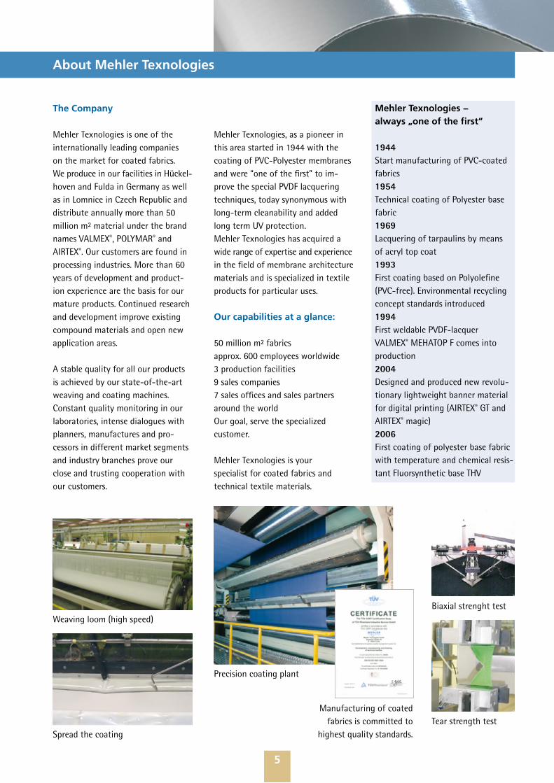
Weaving loom (high speed)
Spread the coating
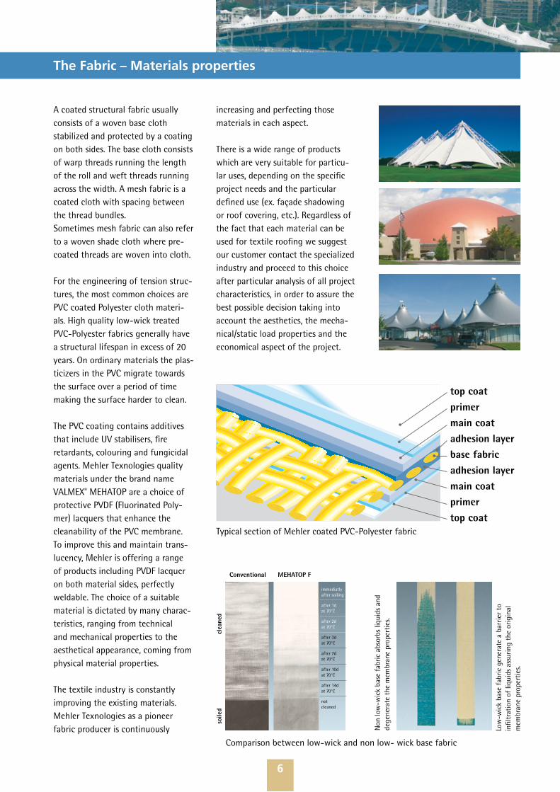
Precision coating plant
Manufacturing of coated fabrics is committed to
highest quality standards.
Biaxial strenght test
Tear strength test
6
The Fabric – Materials properties
A coated structural fabric usually consists of a woven base cloth stabilized and protected by a coating on both sides. The base cloth consists of warp threads running the length of the roll and weft threads running across the width. A mesh fabric is a coated cloth with spacing between the thread bundles. Sometimes mesh fabric can also refer to a woven shade cloth where pre-coated threads are woven into cloth. For the engineering of tension struc-tures, the most common choices are PVC coated Polyester cloth materi-als. High quality low-wick treated PVC-Polyester fabrics generally have a structural lifespan in excess of 20 years. On ordinary materials the plas-ticizers in the PVC migrate towards the surface over a period of time making the surface harder to clean.
The PVC coating contains additives that include UV stabilisers, fire retardants, colouring and fungicidal agents. Mehler Texnologies quality materials under the brand name VALMEX® MEHATOP are a choice of protective PVDF (Fluorinated Poly-mer) lacquers that enhance the cleanability of the PVC membrane. To improve this and maintain trans-lucency, Mehler is offering a range of products including PVDF lacquer on both material sides, perfectly weldable. The choice of a suitable material is dictated by many charac-teristics, ranging from technical and mechanical properties to the aesthetical appearance, coming from physical material properties.
The textile industry is constantly improving the existing materials. Mehler Texnologies as a pioneer fabric producer is continuously
increasing and perfecting those materials in each aspect.
There is a wide range of products which are very suitable for particu-lar uses, depending on the specific project needs and the particular defined use (ex. façade shadowing or roof covering, etc.). Regardless of the fact that each material can be used for textile roofing we suggest our customer contact the specialized industry and proceed to this choice after particular analysis of all project characteristics, in order to assure the best possible decision taking into account the aesthetics, the mecha-nical/static load properties and the economical aspect of the project.
top coatprimermain coatadhesion layerbase fabricadhesion layermain coatprimertop coat
Low
-wic
k ba
se f
abric
gen
erat
e a
barr
ier
to
infil
trat
ion
of li
quid
s as
surin
g th
e or
igin
al
mem
bran
e pr
oper
ties
.
Typical section of Mehler coated PVC-Polyester fabric
Comparison between low-wick and non low- wick base fabric
Non
low
-wic
k ba
se f
abric
abs
orbs
liqu
ids
and
dege
nera
te t
he m
embr
ane
prop
erti
es.
immediatlyafter soiling
after 1dat 70°C
after 2dat 70°C
after 3dat 70°C
after 7dat 70°C
after 10dat 70°C
after 14dat 70°C
notcleaned
soile
d
c
lean
ed
Conventional MEHATOP F
7
Materials types
In the architectural segment, mem-branes made by Mehler Texnologies are multilayered composite materials with special densely woven low-wick yarns in base fabric. The double thread woven fabric, commonly described as “Panama” weave, varies depending on the mechanical resistance reques-ted by the customers. The different membrane materials are graded by weight and strength, and an overview of the standard types of materials is listed below.
Mehler Texnologies materials are basically ”pre-stressed” with different force grades in both directions. The
warp direction (length of the material roll) has less stretch to stabilize the elongation in this sense. The weft direction (the width side of the mater-ial roll) has more stretch in order to absorb the orthogonal tension more readily during the distensile install-ation process* (see graphic below).
Professionals like to maneuver the compensation ratio of the fabric material during the patterning process in order to generate ad-hoc geo-metries and unique smooth surfaces. This process is generally considered “top secret” to most of them and is also the core of the well qualified
textile architecture engineer or specialized manufacturer.
This requires a certain kind of techni-cal information generated by com-puter analysis, simulation and testing processes, generated case by case for each project.
Mehler Texnologies can provide to the customer biaxial results for each produced batch of material. The tests are executed on client request to external accredited laboratories based on MSAJ/M-02-95 procedure.
Overview of Mehler Texnologies architecture PVDF-coated material types
fewer seams
lower manufacturing costs
lighter equipment
shorter assembly times
lower erecting costs
Attractive widths
VARIO-STRETCH:less stretchin warp directionthanin weft direction
very flexible easier handling
high strength higher safety
lacquered both sides more durable
high gloss attractive appearance
no need to grind directly weldable
Example of asymmetrical curvature shapes with symmetrical primary structure, only generable by using VARIO-STRETCH fabric, properly compensated.
Weft
War
p
*
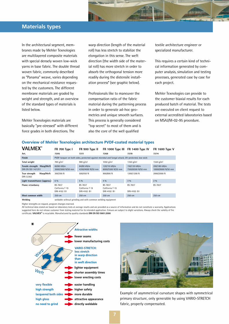
VALMEX® FR 700 Type I FR 900 Type II FR 1000 Type III FR 1400 Type IV FR 1600 Type VArt. 7205 7211 7269 7270 7274
Finish PVDF-lacquer on both sides, protected against microbal and fungal attack, UV-protected, low-wick
Total weight 700 g/m² 900 g/m² 1050 g/m² 1350 g/m² 1550 g/m²
Tensile strength Warp/Weft 60/60 kN/m 84/80 kN/m 120/110 kN/m 150/130 kN/m 200/180 kN/mDIN EN ISO 1421/V1 3000/3000 N/50 mm 4200/4000 N/50 mm 6000/5500 N/50 mm 7500/6500 N/50 mm 10000/9000 N/50 mm
Tear strength Warp/Weft 300/300 N 500/450 N 900/800 N 1200/1200 N 2000/2000 NDIN 53363
Light transmittance (approx.) 6 % 5 % 4 % 3 % 2 %
Flame retardancy BS 7837 BS 7837 BS 7837 BS 7837 BS 7837 California T 19 California T 19 California T 19 DIN 4102: B1 DIN 4102: B1 DIN 4102: B1 DIN 4102: B1
Most common width 250 cm 250 cm 250 cm 250 cm 250 cm
Welding weldable without grinding and with common welding equipment
Higher strengths on request, program changes reserved.All technical data stated are based on laboratory tests at average results and are provided as a source of information and do not constitute a warranty. Applications suggested here do not release customer from testing material for its intended application. Colours are subject to slight variations. Always check the validity of fire certificate. VALMEX® is recyclable. Manufactured by quality standards DIN EN ISO 9001:2000
8
Advantages of weldable PVDF coated fabrics
Mehler Texnologies, a pioneer in PVC-PES coatings, introduced more than 14 years ago weldable PVDF coated membrane. In our opinion, the textile industry should provide products to the market which can perform without the need to be modified, ground or manipulated by the fabricator. The industry should assume in full the material properties responsibility, not delegate this to additional substances, to manipula-tions of the surface, to the uncon-trolled machines operation capability or simply to human factor.It is wrongly assumed that the weldability of PVDF coated material is given by the percentage of PVDF included into the top coat.
Mehler’s PVDF coated fabrics, incorporates a primer between the top coating lacquer and the PVC coating, completing 5 components in the building up of the product (s. schematic picture at page 5). Other manufacturers show 3 to maximum 4 components (base fabric, adhesion layer (some), coating, lacquer).
This is the reason why our fabric is weldable, easy to manufacture and stable (non-peeling). A properties comparison with non-weldable PVDF coated materials follows.
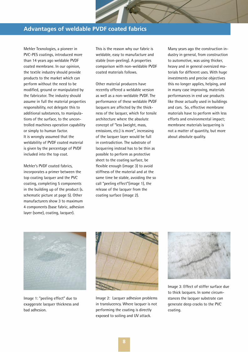
Other material producers have recently offered a weldable version as well as a non-weldable PVDF. The performance of these weldable PVDF lacquers are affected by the thick-ness of the lacquer, which for tensile architecture where the absolute concept of “less (weight, mass, emissions, etc.) is more”, increasing of the lacquer layer would be full in contradiction. The substrate of lacquering instead has to be thin as possible to perform as protective sheet to the coating surface, be flexible enough (image 3) to avoid stiffness of the material and at the same time be stable, avoiding the so call “peeling effect”(image 1), the release of the lacquer from the coating surface (image 2).
Many years ago the construction in-dustry in general, from construction to automotive, was using thicker, heavy and in general oversized ma-terials for different uses. With huge investments and precise objectives this no longer applies, helping, and in many case improving, materials performances in end use products like those actually used in buildings and cars. So, effective membrane materials have to perform with less efforts and environmental impact; membrane materials lacquering is not a matter of quantity, but more about absolute quality.
Image 1: “peeling effect” due to exaggerate lacquer thickness and bad adhesion.
Image 2: Lacquer adhesion problems in translucency. Where lacquer is not performing the coating is directly exposed to soiling and UV attack.
Image 3: Effect of stiffer surface due to thick lacquers. In some circum-stances the lacquer substrate can generate deep cracks to the PVC coating.

9
Comparison PVC/PES-Fabrics with weldable/ non-weldable PVDF coating
Comparison PVC/PES-Fabrics with weldable/ non-weldable PVDF coatingProduct
SpecificationPVC/PES-PVDF
weldablePVC/PES-PVDF non weldable
MATERIAL PROPERTIESBasic fabric PES (Polyester) PES (Polyester)Type of coating PVC (Polyvinylchlorid) PVC (Polyvinylchloride)Top-coating variation
Primer +blended PVDF(polyvinylidene floride)
(Mehatop F)
Variable concentrated mixture of PVDF (polyvinylidene floride) with other amalgamating lacquers compounds
Total weight approx. 650 to 1550 [g/m²] approx. 750 to 1500 [g/m²]Tensile strength warp
approx. 2500 to 9800 [N/5 cm] approx. 3000 to 9800 [N/5 cm]
Tensile strength in fill
approx. 3000 to 8300 [N/5 cm] approx. 3500 to 6500 [N/5 cm]
Material roll width 250 cm (Standard) approx. 180 cm (Standard)Thickness up to 1,2 mm up to 1,2 mmTranslucence up to 15 % up to 15 %Flammability Flame retardant according to
DIN 4102, B1Flame retardant according to
DIN 4102, B1as well as other classes as well as other classes
Colour standard white, extensive colour choice , no bleaching
standard white, extensive colour choice , no bleaching
Manufacturing, Handling, InstallationManufacture devices preparation
Standard HF machine function tests
Standard HF machine function tests. Grinding machine: adjustment of the grinding parameters and replacement of grinding strip based on request. Preparing of grinding work area.
Weldability Standard HF weldable without grinding the surface top coating. Welding seams strength and resistance are constant.
Top coat lacquer needs to be ground with abrasive machines. Risk of damaging the basic fabric/ reducing depth of the PVC coating or insufficient removing of the top coat lacquer when parameters or abrasive strip properties are changed. High risk of inconsistent welding seams, strength and resistance.
Foldability Standard comparable to PVC Acrylic coated materials. Based on Crack resistance test DIN 53359 A+B ÈNo crack @ 100.000 tours
Not defined. Depending on the thickness of the lacquer may result to be difficult to high difficult, due to stiffer surface conformation. Risk of abrasion on doubled folded areas andcrack of the whole coating compound higher.
Manufacturing facility special resources
None Large area for folding operation is necessary. Grinding space to be isolated and separated from manufacturing space. Grinding particle pollution contaminate working atmosphere. Patterns and pattern seams collect additional dirt.
Human resource special resources
None Persons using grinding machine or working in the near proximityneed to wear minuscule particle masks and protective glasses.
Seams and/or welding areas preparation
None Grinding seam lines to be sketched on and along the material surface. Membrane reinforcement area (cone top, corners, etc.) needs to be ground by hand or using off-axis grinding machines.
On site welding, repairs and preparation
Standard skill required: direct welding to carry out by means
of hot air welding machines
Special skill required: welding areas are to be ground off by means of off-axis grinding machines. Especially in case of close flaps welding it may require additional working time and additional human safe harness equipment. Higher risk of main membrane damage. Higher risk of insufficient welding resistance performance. Higher risk of additional dirt collecting into the welding areas. Direct welding to carry out by means of hot air welding machines
GeneralCost evaluative(material/ processes)
Low. Add factors, well foldable, easy welding and
short installation.
Higher. Add factors, complicate by handling, quietly stiff, difficult manufacture process and long term installation process in case of site welding (close flaps, site joints, etc.).
Recycling Full recycling possible Full recycling possibleExpected lifetime > 25 years > 25 yearsSelf- cleaning effect Good, where necessary
during normal maintenance cleanable with standard non-
solvent cleaning agents
Very good, where necessary during normal maintenance cleanable with standard non-solvent cleaning agents
Warranties Standard ¹ 10 years, can vary depending on project
requirements
Standard ¹ 10 years, can vary depends from project requirements
Application field Standard systems, temporary and permanent constructions,
mobile and foldable constructions
Standard systems, temporary and permanent constructions

10
General performances
Wind
A frequently asked question is if membrane structures are suitable for permanent installation on windy sites. The answer is usually „yes, as long as the project is properly engineered”. Today it is possible to generate computer analysis of the different load cases which show that the wind load is the major load case in any scenario. The detailing of the fittings and surrounding structure play an important role and needs to take into account the maximum deflections of the membrane. Under extreme circumstances the engineer-ing and material choice has to be carried out with particular attention. Designing for permanent load cases (downloads are e. g. snow and sand, uploads are generated by wind suction) requires extreme care as there is a greater risk of form finding mistakes such as e.g. water pounding or sand build up (which can cause permanent uncontrolled stretching of the structure). In these circum-stances, the fabric forms generally need to be steeper, spans smaller, curvature greater and sometimes, intermediate cables needs to be introduced as fabric support.
Fire
The fire performance of a membrane material depends on the base fabric and coating type. All membrane materials will melt under higher tem-peratures, even if at different grades.VALMEX® FR is difficult to ignite and passes many national fire tests. The speed of this process depends on the type of coating, the temperature reached into the covered space in fire situations and the pretension in the membrane. The effect in a fire situa-tion is beneficial for the persons due to the fact that melted areas gene-rate self-venting opening through a failed seam in the membrane surface and consequently a natural smoke reservoir (which may allow sufficient time for escape, when sufficiently hot) will occur. There is no risk of burning droplets or fire propagation on the material surface.Additionally, the reduced mass avoids high weights falling down. Designers should consider smoke and collateral effects generated by the material used.
The fire performances of materials are classified based on their perfor-mances in case of fire dictated by the material behaviour of the project requirements. As well know, PVC will melt with non-drops consequences
Mehler Texnologies fabrics easily pass the majority of quality tests at several institutes and independent testing laboratories in accordance with major worldwide testing mandates.
DIN
at lower temperature than PTFE material. This means that in case flames reach the material surface or the internal temperature reached above approx.100° C, PVC membranes help in exhausting smoke quickly and reducing overburning effects. PTFE on glass will melt at approx. 300°C. In this case, all smoke and gases generated below the surface will be captured within the buil-ding which is a big health threat to the people, destroying a large part of static construction materials. When the temperature reaches the PTFE melting point, welded seams will open suddenly and give way to a flash-point situation, with the conditions existing for the possibility of an explosion due to the emission of oxygen (as example, material rips, melting point or by opening a door). In case of fire PES/PVC melts where the flame reaches the membrane and lets the smoke escape. As a consequence there is no flash-point situation to fear about.
In general, fire rating classifications are only defining the material performances (burning resistance, smoke generation, droplet, ecc.) once exposed to fire sources. Is task of the user (architects, planner or special-ist) in evaluate and integrate those performances into the entire design concept, taking in account what would be better and safer for people and support construction materials, and not for the material itself.
For high point structures critical steelwork should be supported by means of safety cables so that partial failure of a damaged membrane roof will not cause collapse of the suspen-ded structure.
11
General performances
Thermal insulation
A single layer of VALMEX® FR 1000 membrane with a of 1050 g/m2 has a U-value of approx. 5.7 W/m2K (DIN 52611). In this respect it is very simi-lar to glass. A twin skin with a 200 mm air gap will give an approximate U-value of 2.7 W/m2K.
It is possible to get lower U-values than this by using additional material layers to the fabric system. However, this needs to be designed for as it will affect the performance of the entire enclosed space and also will reduce the light transmittance levels.
In certain environment conditions, high reflectance top coating or UV blocking materials can be of interest. This can be a solution for example in case of open air cinemas or circus tents, where the light transmittance would disturb other lighting effects.
Lighting
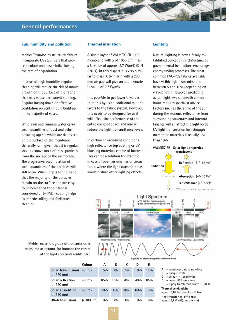
Natural lighting is now a firmly es-tablished concept in architecture, as governmental institutions encourage energy saving processes. The most common PVC-PES fabrics available have visible light transmission of between 5 and 16% (depending on wavelength). However, predicting actual light levels beneath a mem-brane requires specialist advice. Factors such as the angle of the sun during the seasons, reflectance from surrounding structures and internal finishes will all affect the light levels. UV light transmission lost through membrane materials is usually less than 10%.
Radiation Reflection (+/- 85 %)*
Absorption (+/- 10 %)*
Transmittance (+/- 5 %)*
VALMEX® FR Solar light properties - translucent -
02/2006 * for standard white, method Mehler Texnologies - ASTM E 424, at 550 nm
Colour A B C D ESolar transmission approx 5% 0% 0.5% 0% 12%(at 550 nm)
Solar reflection approx 85% 85% 70% 40% 85%(at 550 nm)
Solar absorbtion approx 10% 15% 30% 60% 3%(at 550 nm)
UV-transmission (<380 nm) 0% 0% 0% 0% 0%
A = translucent, standard whiteB = opaque whiteC = colour 141 pearlwhiteD = colour 852 sandstoneE = highly translucent, white 919/008
Thermal conductivity:approx 0,18 Watt/(meter x Kelvin)
Heat transfer co-efficient: approx 5,7 Watt/(sqm x Kelvin)
Mehler materials grade of transmission is measured at 550nm, for humans the centre
of the light spectrum visible part.
Sun, humidity and pollution
Mehler Texnologies structural fabrics incorporate UV stabilisers that pro-tect colour and base cloth, slowing the rate of degradation.
In areas of high humidity, regular cleaning will reduce the risk of mould growth on the surface of the fabric that may cause permanent staining. Regular hosing down or effective ventilation prevents mould build up in the majority of cases.
Wind, rain and running water carry small quantities of dust and other polluting agents which are deposited on the surface of the membrane. Generally rain, given that it is regular, should remove most of these particles from the surface of the membrane. The progressive accumulation of small quantities of the particles will still occur. When it gets to the stage that the majority of the particles remain on the surface and are easy to perceive then the surface is considered dirty. PVDF coating helps to impede soiling and facilitates cleaning.

Farbe Front / faceColour Rück / reverse
Strahlungstransmission %Solar transmission %(DIN EN 410)
Strahlungsreflexion %Solar reflection %(DIN EN 410)
Strahlungsabsorption %Solar absorption %(DIN EN 410)
Sonnenschutzfaktor innenInternal solar protection factor(DIN EN 14501)
Sonnenschutzfaktor außenExternal solar protection factor(DIN EN 14501)
Sächsisches Textil Forschungsinstitut, Prüfbericht 0344/05* Silber der Sonne zugewandt / Silver to the sun
12
Special materials application − Façades
Buildings able to adapt to changing climatic conditions are commonly termed “intelligent buildings”. Since the term intelligent can be mislead-ing when used in the context of buildings or façades, we will better use the term “adaptive façade” instead. Adaptation generally means that buildings and façades adapt to current weather conditions, espe-cially directed to the sun protection functionality.
To meet this challenge Mehler created the Flashguard® fabric which has been designed to meet the specific requirements of sun pro-tection systems and is suitable for both indoor and outdoor use. The exceptional material properties of Flashguard® reduce sunrays to create a pleasant room climate. The use of sun protection fabrics negates the need for expensive air conditioning, e.g. for maintaining productivity and protecting temperature sensitive devices. This helps to considerably reduce energy costs.
Sun protection fabrics contribute to save energy by absorbing or reflec-ting the main portion of energy contained in sunrays before these can heat the room. Particularly in the hot summer months, sun protection fabrics provide for a pleasant room
temperature producing an effective working atmosphere.
The use of energy-intensive air conditioning equipment such as air conditioning systems, fans or air conditioning units is reduced and in many cases unnecessary.
The open fabric structure of Flashguard® provides natural light. Dazzling sunlight, which has a detrimental effect on health particularly at com-puter work-stations, is prevented. In addition, the open fabric structure is see-through from the inside, but not from the outside, providing a high level of privacy. It allows natural light to pass through.
Flashguard® fabric uses 100% Polyes-ter. It is highly stable, weatherproof and extremely durable in long term use. It is capable of withstanding temperatures between -30°C and +70°C. The special PVC coating makes the open fabric particularly dirt-repellent and easy care. It is flame-retardant according to test standard CERF Category 1, NFPA 92507 M2, DIN 4102 B1. Owing to the use of high-quality colour pigments and UV stabilizers, Flashguard® is ex-tremely light and weather-resistant and keeps its appearance over a long period.
The fabric has a low thickness of 0.45 mm, has a low weight of 380 g/m² and has reliable roll up and unroll properties, enabling Flashguard® to be inserted in space-saving roll up devices. Flashguard® • Contributes to reducing energy
costs• Generates pleasant room tempera-
ture• Re-create natural illumination• Avoids dazzling sunlight at compu-
ter workstations, increases product-ivity by creating a pleasant work atmosphere
• Space-saving by low thickness and light weight
• Easy roll-up and unroll properties• Dirt-repellent and easy care• Flame-retardant• Keeps its appearance over a long
period• Light-, weather- and colour-fade
resistant
907901
23
66
11
0,51
0,25
275275
14
64
22
0,52
0,17
858858
17
57
26
0,57
0,22
809809
12
47
41
0,63
0,16
177177
18
60
22
0,55
0,21
190190
18
54
28
0,59
0,22
333333
24
40
35
0,68
0,32
820820
12
8
80
0,88
0,26
608608
16
30
54
0,74
0,23
584584
16
34
50
0,72
0,26
536536
21
27
52
0,76
0,31
729729
15
54
31
0,59
0,19
758758
10
20
70
0,80
0,22
911*911
17
47
36
0,63
0,24
911*907
14
58
28
0,56
0,17
911*275
11
55
34
0,57
0,15
Sun light
R A T SA
GlazingFlashguard®
T
R
A
SA
13
Environment and sustainability
Mehler Texnologies and our label for Environment Engage-ment
Mehler Texnologies believes that the preservation of the environment is much more than “waste manage-ment” as may be the case of the sole recycling tasks. All activities have now been bundled under one all-embracing label.
Mehler, as one of the largest coaters in the world, producing more than 50Mil.m² fabric products per year, is operating on a vast scale of activities, and has taken prevention activities on raw materials, the whole product-ion process, and lastly taking care of the finished waste.
Beside our own policy, and following the EU regulation on use of chemi-cals, Mehler has for many years sup-ported various EU-based associations pro-actively, contributing in reduced emissions, thus helping to preserve the environment.
Our commitment to the environment starts with the raw materials select-ion. To do this, Mehler is selecting all chemical compounds based on the REACH (see attached statement) regulation. No one single additive rejected by the REACH rules is, or will be, utilized by our technicians to ful-fil any performance of our materials.
The production process is strongly controlled and all machinery has been optimized to reduce energy along the coating process; additio-nally, some years ago Mehler invested millions of Euros to reduce the
emissions of CO2, in line with the EU environment protection require-ments.
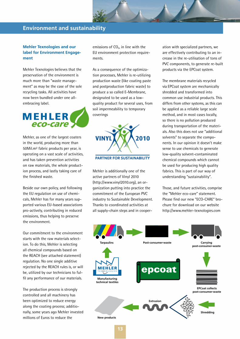
As a consequence of the optimiza-tion processes, Mehler is re-utilizing production waste (like coating paste and postproduction fabric waste) to produce a so called E-Membrane, designated to be used as a low-quality product for several uses, from soil impermeability to temporary coverings
Mehler is additionally one of the active partners of Vinyl 2010 (http://www.vinyl2010.org), an or-ganization putting into practice the commitment of the European PVC industry to Sustainable Development. Thanks to coordinated activities at all supply-chain steps and in cooper-
ation with specialized partners, we are effectively contributing to an in-crease in the re-utilisation of tons of PVC components, to generate re-built products via the EPCoat system.
The membrane materials recycled via EPCoat system are mechanically shredded and transformed into common use industrial products. This differs from other systems, as this can be applied as a reliable large scale method, and in most cases locally, so there is no pollution produced during transportation of the materi-als. Also this does not use “additional solvents” to separate the compo-nents. In our opinion it doesn’t make sense to use chemicals to generate low-quality solvent-contaminated chemical compounds which cannot be used for producing high quality fabrics. This is part of our way of understanding “sustainability”.
Those, and future activities, comprise the ”Mehler eco-care” statement. Please find our new ”ECO-CARE“ bro-chure for download on our website http://www.mehler-texnologies.com
Manufacturing technical textiles
Carrying post-consumer-waste
EPCoat collects post-consumer-waste
Shredding
Extrusion
New products
Post-consumer-wasteTarpaulins

14
Design
Membrane constructions can be sub-ject to tensile stress only due to the low compressive and bending rigidity of their surfaces. However, plane surfaces react sensitively to defor-mation by external loads. They tend to flutter and to create snow and water-traps, which in extreme cases can lead to failure of the construc-tion. The stabilization of plane areas would require uneconomic high pre-stressing. Consequently, design and draft follow completely different principles than other supporting structures, which are mainly bending or compressive stressed. In particular the difference is that the process of design of mainly tensile stressed membrane constructions mostly develops self-regulation.
This means, that either the form of the membranes approaches the form of so called “minimum surfaces”, (following physical principles under the condition of similar surface stresses within defined continuous edge elements), or it is influenced by changing the boundary conditions, or by inserting additional supporting elements (which can be linear, plane or supported at certain points) res-pectively by different surface stress preconditions. This allows creating either “anticlastic” saddle shape sur-faces or generating “synclastic” sur-faces when using pneumatic internal pressure like a balloon. Supporting media for producing internal pressure can be air, gas, water or other liquids but also granulated materials.
Geometry and forces defined inde-pendently of the materials used.
A completely free invented design form therefore must be compelled with the help of additional compres-sion and/or bending-stressed carrying elements and at partly inadequately high pre-loading and/or construction expenditure.
Examples of design by construction, rendering and model making:First price of Mehler Texnologies‘ VALMEX® Structure Award 2007 by Architect Sra. Eliana Ferreira Nunes from Brazil.
15
Design
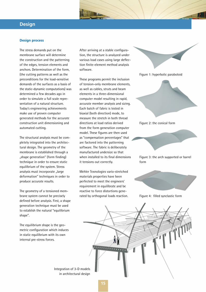
Figure 1: hyperbolic paraboloid
Figure 2: the conical form
Figure 3: the arch supported or barrel form
Figure 4: filled synclastic form
Design process
The stress demands put on the membrane surface will determine the construction and the patterning of the edges, tension elements and anchors. Determination of the form, (the cutting patterns as well as the preconditions for the load-sensitive demands of the surfaces as a basis of the static-dynamic computations) was determined a few decades ago in order to simulate a full scale repre-sentation of a natural structure. Today‘s engineering achievements make use of proven computer generated methods for the accurate construction unit dimensioning and automated cutting.
The structural analysis must be com-pletely integrated into the architec-tural design. The geometry of the membrane is established through a „shape generation‘‘ (form finding) technique in order to ensure static equilibrium of the system. Stress analysis must incorporate „large deformation‘‘ techniques in order to produce accurate results.
The geometry of a tensioned mem-brane system cannot be precisely defined before analysis. First, a shape generation technique must be used to establish the natural “equilibrium shape”.
The equilibrium shape is the geo-metric configuration which induces in static equilibrium with its own internal pre-stress forces.
After arriving at a stable configura-tion, the structure is analyzed under various load cases using large deflec-tion finite-element method analysis software.
These programs permit the inclusion of tension-only membrane elements, as well as cables, struts and beam elements in a three-dimensional computer model resulting in rapid, accurate member analysis and sizing. Each batch of fabric is tested in biaxial (both direction) mode, to measure the stretch in both thread directions at load ratios derived from the form generation computer model. These figures are then used as “compensation percentages” that are factored into the patterning software. The fabric is deliberately manufactured undersize so that when installed to its final dimensions it tensions out correctly.
Mehler Texnologies vario-stretched materials properties have been perfected to meet the engineers’ requirement in equilibrate and be reactive to force distortions gene-rated by orthogonal loads reaction.
Integration of 3-D models in architectural design

16
Form finding and pretensioning
Permanent tensile membrane struc-tures are designed to resist the same basic loading criteria as conventional buildings. Imposed minimum live loads and wind pressures are derived from the requirements of the local building code or the model code having jurisdiction.
This architecture needs a symbiosis of live forces in each situation. The force generating those forms is the tension transmitted and governed by the material. Pretension is defined as the tensile forces in the fabric after erection but prior to external loads being applied.
The ratio of pre-stress in the principle curvature directions, which dictates the shape, is initially established in the computer form generation process. The absolute values of pre-stress are calculated to be sufficient to keep all parts of the membrane in
tension under any design load case. Imposed loads are resisted by redis-tribution of the stresses within the membrane system. If this results in any area going into compression then creases will appear and in critical cases generate form distortions until structure collapse.
Similarly, if the pretension is not properly distributed or not high enough then substantial movement of the structure could occur with consequent destabilization of the whole tensile structure.
Detailing
Once analyzed form and material properties will be necessary to carry out a preliminary statistical analysis.
As part of the preliminary design process a provisional load analysis derived from a computer model will give typical load directions and figures of the design loads to be transferred to the supporting structure. By des-cribing the supporting structure, the type of connections and all accessory parts like the perimetral links, anchor plates and corner devices are to be dimensioned properly.
The boundary of the membrane usu-ally falls into one of two categories: curved and scalloped edges.
These generally consist of a cable sitting in a pocket at the edge of the membrane. In some structures, webb-ing belts can be added parallel to the edge to take out the shear loads. Membrane edges can also be linearly fixed. Usually there is a rope edge also called “keder” formed by sealing a flexible PVC rod in a small pocket. This can then be trapped behind an aluminium clamp plate bolted direct-ly onto the structural steel work or slid into an aluminium track extrusion.
A properly designed fabric structure should take account of these elements as well as all other particulars to minimise membrane material waste.
Example of corner fitting plate device
Proper material compensation and fine-tuning application of the bi-axial values (as well as material high quality mechanical properties) are here highly demanded. Those factors when properly evaluated are avoiding “relaxing” of the membrane surface and consequent re-tensioning needs. Mehler Texnologies materials are commonly performing in the time (s. FAQ section this guideline, at point 3. What consideration should we allow for the membrane material service life?), with proven and excellent values.
Computerized load analysis on the membrane material in warp direction.
Higher stress concentration in weft direction. Note the different loads distribution on both directions of the membrane surface.
Use of complicated devices and non-standardized forms will seriously affect the design and the commercial aspect of the project.
17
Manufacture
The fabrication of the membrane fabrics is a specialist activity and re-quires experienced personnel, special materials and facilities adapted for the works. Experienced manufac-turers secure a QA manager to over-see the quality aspect of the fabrica-tion and conduct the final inspection and acceptance of the finished mem-brane.
The cutting patterns are generated using 3D computer models of the structure and taking into account the required compensations for the individual production weave batches of membrane material and the edge corrections for welding seams and edge details. These electronic cutting patterns are then transferred by a computer into a controlled cutter/plotter. The joining or assembly process of the single membrane area (patterns)for the PVC-coated fabrics is normally per high frequency induction. To this end the main tools for fabrication are purpose built welding machines. Periodical measurement of the main parameters, like the output tempera-ture or the executed pressure level of the machines will be carried out by common external gauges. The hand-held welding process by means of hot-gun tools are used to do the detail work at corner etc.
The production itself can be sub-divided into four phases: delivery and quality inspection of the material, cutting, welding and packing.
In case of non weldable Top coat lacquer, this needs to be ground with abrasive machines. Risk of damage to the base fabric/ reduces the depth of the PVC coating or insufficient re-moving of the top coat lacquer when parameters or abrasive strip proper-ties change needs to be minimized by paying particular attention. High risk of inconsistent welding seams strength and resistance can occur. Persons using grinding machine or working in close proximity need to wear minuscule particle masks and protective glasses. The work area de-signated to grind needs to be isolated from the rest of the facility.
During the production process, records are made of all the work steps to guarantee state-of-the-art workmanship. The manufacture pro-cess of fabric membranes does not bear any significant environmental risks. All waste materials are disposed of in accordance to governmental regulations.
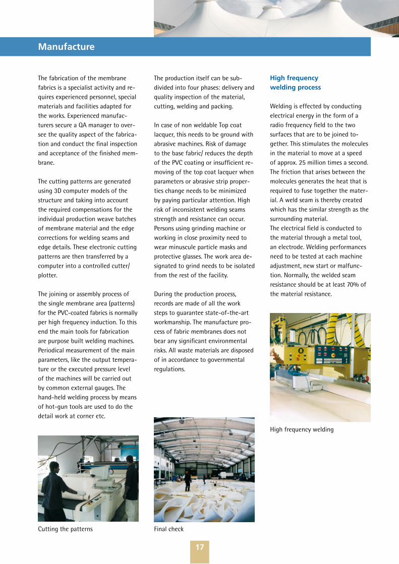
High frequency welding process
Welding is effected by conducting electrical energy in the form of a radio frequency field to the two surfaces that are to be joined to-gether. This stimulates the molecules in the material to move at a speed of approx. 25 million times a second. The friction that arises between the molecules generates the heat that is required to fuse together the mater-ial. A weld seam is thereby created which has the similar strength as the surrounding material.The electrical field is conducted to the material through a metal tool, an electrode. Welding performances need to be tested at each machine adjustment, new start or malfunc-tion. Normally, the welded seam resistance should be at least 70% of the material resistance.
High frequency welding
Cutting the patterns Final check
18
Installation
The installation of the fabric systems is a highly specialized area of work requiring experienced personnel and special access equipment. However the tools and other equipment are standard items used in conventional construction rigging.
Most of the roofing materials, i.e. membrane fabric, cables, etc. are relatively lightweight, but access has to be provided for most of the construction area.
One of the biggest advantages of membrane structure is the easy, clean and quick installation and adjust-ment process. Because of its light-weight no heavy hoisting equipment is required to get it in place and specialist riggers can install them in most cases practically by hand.
The main functions of the installa-tion of the fabric roof are verifying the tolerances of the main structure, installment of the temporary works, securing of the primary structures, and the quality and safety control process of the installation.
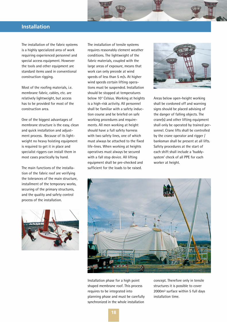
Installation phase for a high point shaped membrane roof. This process requires to be integrated into planning phase and must be carefully synchronized in the whole installation
The installation of tensile systems requires reasonably clement weather conditions. The lightweight of the fabric materials, coupled with the large areas of exposure, means that work can only precede at wind speeds of less than 5 m/s. At higher wind speeds certain lifting opera-tions must be suspended. Installation should be stopped at temperatures below 10° Celsius. Working at heights is a high-risk activity. All personnel shall be familiar with a safety induc-tion course and be briefed on safe working procedures and require-ments. All men working at height should have a full safety harness with two safety lines, one of which must always be attached to the fixed life-lines. When working at heights operatives must always be secured with a fall stop device. All lifting equipment shall be pre-checked and sufficient for the loads to be raised.
Areas below open-height working shall be cordoned off and warning signs should be placed advising of the danger of falling objects. The crane(s) and other lifting equipment shall only be operated by trained per-sonnel. Crane lifts shall be controlled by the crane operator and rigger / banksman shall be present at all lifts. Safety procedures at the start of each shift shall include a ‘buddy-system’ check of all PPE for each worker at height.
concept. Therefore only in tensile structures it is possible to cover 2000m² surface within 5 full days installation time.
19
Maintenance
The Mehler Texnologies membrane material is weather resistant and should provide many years of trouble free service life. However, the fabric can be cut or torn, and damaged by a sharp impact; it can be crushed if sub-jected to high localised ‘pinching’ loads, caused by bad design or by inappropriate clamping devices. Care must therefore be taken in handling the material at any process stage and while walking on it, to protect against accidental damage. Inspec-tors and workmen working on this roof must wear clean, soft, white-soled shoes. Care must be taken not to drag any tools or equipment across the surface which may lead to premature deterioration of the roof material.
On structures of this type, the mem-brane is a structural part of the roof system, and not just a protective cover. It is mechanically pre-tensioned to provide a stable roof system capable of withstanding the design conditions of wind, sand, weather etc. However, if damaged, redistribu-tion of load can result in a concen-tration of stress that could cause a propagation of tears. Minor problems can become major if neglected. In order to assure proper service life, it is essential that good operation and maintenance practices are adopted and strictly adhered to.
A continuing awareness of the con-dition of the membrane is essential. Throughout the life of the structure there shall be visual inspections con-ducted to spot any obvious damage or deficiencies. If any are found they shall be further investigated and action taken to repair or correct as deemed necessary. Emergency repairs to the membrane material shall be carried out by persons experienced in working with this. One of the great advantages of the VALMEX® MEHA-TOP FR materials is that even if PVDF coated, they are perfectly weldable without grinding of the surface, even on site, by means of hot-air gun tools.
Depending on the project location (and the maintenance dedicated to the membrane covering) small quantities of dust and other pollut-ing agents could deposits itself on the surface, degenerating the natural beauty. Generally rain removes most of these particles but when it gets to the stage that the majority of the particles remain on the surface and are easy to perceive then the surface is considered dirty.
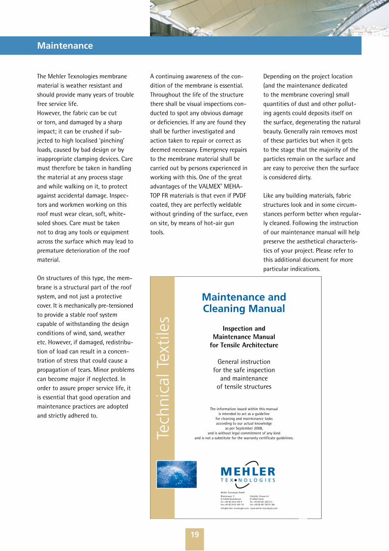
Like any building materials, fabric structures look and in some circum-stances perform better when regular-ly cleaned. Following the instruction of our maintenance manual will help preserve the aesthetical characteris-tics of your project. Please refer to this additional document for more particular indications.
Tech
nica
l Tex
tile
s
Mehler Texnologies GmbH
Rheinstrasse 11 Edelzeller Strasse 44D-41836 Hückelhoven D-36043 FuldaTel. +49 (0) 2433 459 0 Tel. +49 (0) 661 29275 0Fax +49 (0) 2433 459 151 Fax +49 (0) 661 29275 366
[email protected] · www.mehler-texnologies.com
Maintenance and Cleaning Manual
Inspection and Maintenance Manual
for Tensile Architecture
General instruction for the safe inspection
and maintenance of tensile structures
The information issued within this manual is intended to act as a guideline
for cleaning and maintenance tasks according to our actual knowledge
as per September 2008, and is without legal commitment of any kind
and is not a substitute for the warranty certificate guidelines.
20
Condensation
In some climatic conditions, internal condensation is likely to occur with roofs covering a sealed heated space. Appropriate design of roof gradients and edge detailing can minimise any problems. Ventilation can obviously reduce the risk but if more control is required then it is often necessary toincorporate a second layer. Controll-ing the airflow in the air gap bet-ween two fabric layers is recommen-ded to get the best environmental control. A sealed air gap is best in winter for insulation and a good air-flow in the summer will help cooling.
The design of roofs (particularly in conic forms) can make use of a “passive stack effect” where natural airflow along the surface of the fabric is enhanced. This may be artificially reproduced by fans or louvers, to achieve the required performance and to reduce the risk of fungal attack.
Therefore, in addition to the inherent protective additives in the material, it is of high importance that for the design itself, adequate gradients and edge detailing are considered to optimize the natural ventilation and minimise any problems. Ventilation, in natural or artificial way, can ob-viously reduce the risk but based on our experience, this is not the only aspect to take in account.
In case of pneumatical structures (it is not a matter which material will be used) more control is required and then it is often necessary to incorpo-rate a dryer between the air blowing and the internal skin chambers. The dryers prevent the temperature difference (outside/inside) that can generate water condensation in-between the layers, even if there is a permanent air blowing occurring. To reduce the risk of fungal attack, periodical cleaning of the surface by use of simply clear water is required. Experienced designer’s use high point structures to allow the natural “ne-gative thermal buoyancy” generated by the roof form to grant permanent air flow and at same time excess of “vitiated” air evacuation.
Long exposed surfaces, especially when not maintained, are more exposed to fungal accumulation and consequently to aesthetical (and in extreme cases physical) deteriorating of the material properties.
In general the designer takes care of this on permanent structures; there the problem can appear where venti-lation of the inner surface is insuffi-cient or there are “static areas” where differences in outside/inside tem-
perature which generate condensa-tion are not exposed to adequate ventilation. Also, is possible that during installation there may be damages to the lacquer (ex. by sliding the membrane on the floor or simply carrying the material over a cable fitting, etc.) which generates an opening on the coating, exposing the material to UV and water penetra-tion.
The problem becomes significant on temporary structures, where it is necessary to erect and dismantle several times, and in most cases, quickly stored for the next event. There the risk of damage to the lacquers, coupled with humidmaterial, can cause serious problems. Moisture can not only come from rain, but also from condensation (water forming itself when fabric has been folded and packed, without any protection (as the membrane folded generates multilayered, almost “sealed” substrates) and stored in sun/shadowing areas or in humid spaces. This is also the problem of some retractable roofs, in particu-lar where dust and water remains accumulated and where ventilation is insufficient.
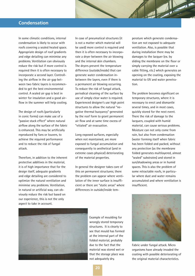
Fabric under fungal attack. Micro organisms have already invaded the coating with possible deteriorating of the original material characteristics.
Example of moulding for wrongly stored temporary structures. It is clearly to see that mould has formed at the internal part of the folded material, probably due to the fact that the material was stored wet or that the storage place was not adequately dry.
21
Frequently Asked Questions
1. Advantages of lightweight, more extensively defined, sus-tainable architecture.
Other than the obvious aesthetical aspect (most tensile structures acquire landmark status much easier than conventional buildings), there are numerous arguments supporting the reasons which have consistently attracted many architects to investi-gate the field of tensile architecture and therefore get involved in projects that incorporate tensile structure which we have witnessed for more than 40 years.The use of this type of architecture generally assists in the drastic reduction of the transformation of raw materials and their utilization, therefore directly contributing in the reduction of environmental impact.Tensile Structures use natural light thus providing translucency, which results in a reduction of artificial
illumination, which allows for natural protection against the elements and ventilation, when engineered properly.Tensile structures perform under tension instead of compression and bending as we find evident in most traditional structures. Furthermore, tensile structures are flexible when compared to traditional building structures which are generally rigid. The aforementioned factors result in tensile structures to be pre-manu-factured and forwarded in smaller containers to site, rapid execution with regards to installation, and the majority of material that was used to be recycled. Mehler Texnologies is participating actively in Vinyl 2010, the self-com-mitment EU association coordinating and financing processes optimization and recycling activities for the PVC-Industry sector. Our point of view regarding active contribution to
preserve our environment is beginn-ing with the strength selection of the chemical compounds as per REACH (Registration, Evaluation and Au-thorisation of Chemicals) regulation coming through CO2 emission reduc-ing investments, recycling process of internal materials rests as well as produced fabrics, to packaging and transportation management tasks.One of the most evident advantages of using lightweight structures is covering a long span as a suspended roof system capacity, which again has the benefits of reducing the material mass used, lowering costs, reducing delivery time and energy savings.This kind of structures can be easily integrated into regular buildings and in many forms of construction, from roof to façade and from ceiling to divisors, improving the physical, the aesthetics and cost effective proper-ties of your project.
2. Interesting, let us talk about lightweight structures, what is that?
Tensile structures are called this because all forces are distributed and they are also commonly lightweight structures and are characterized by mass in relation to the forces work-ing within these structures. Let’s consider a practical example: the weight of 1 square meter of a 7mm float glass for roof construction is approximately 20 kg/m², instead of approximately 1 kg/m² for a type III membrane material, and this without taking into account the enormous sub-structure required involving traditional construction materials.This type of architecture is catego-rized by smooth and harmonious
forms working as tensile (or tension) structures that can be mechanical or pneumatically supported.Commonly, these forms of construc-tion reject the “angular” idea of enclosed space therefore highlighting the beautiful, essential and modern curved design style to a much greater extent.The design process is similar to conventional buildings which are due to the relatively low level of “know how” to the wide spectrum of a non-specialized designer, it requires follow up measures at the very beginning of the whole project design stage. It is important to carry out for example preliminary analysis to define the living loads acting on the foundations. In other words, this means that the design of the tensile
structures should start immediately with the conceptual design carried out by the design architects under the supervision of membrane specia-lists. Mehler Texnologies high quality PVC-Polyester fabrics have been used by pioneers in this field and due to permanent innovation been opti-mized for several uses and diverse customer requirements.
22
Frequently Asked Questions
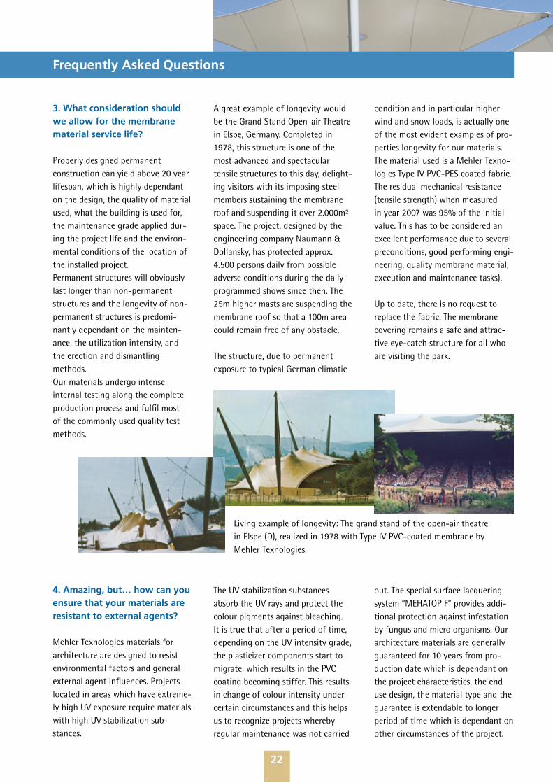
3. What consideration should we allow for the membrane material service life?
Properly designed permanent construction can yield above 20 year lifespan, which is highly dependant on the design, the quality of material used, what the building is used for, the maintenance grade applied dur-ing the project life and the environ-mental conditions of the location of the installed project.Permanent structures will obviously last longer than non-permanent structures and the longevity of non-permanent structures is predomi-nantly dependant on the mainten-ance, the utilization intensity, and the erection and dismantling methods.Our materials undergo intense internal testing along the complete production process and fulfil most of the commonly used quality test methods.
A great example of longevity would be the Grand Stand Open-air Theatre in Elspe, Germany. Completed in 1978, this structure is one of the most advanced and spectacular tensile structures to this day, delight-ing visitors with its imposing steel members sustaining the membrane roof and suspending it over 2.000m² space. The project, designed by the engineering company Naumann & Dollansky, has protected approx. 4.500 persons daily from possible adverse conditions during the daily programmed shows since then. The 25m higher masts are suspending the membrane roof so that a 100m area could remain free of any obstacle.
The structure, due to permanent exposure to typical German climatic
condition and in particular higher wind and snow loads, is actually one of the most evident examples of pro-perties longevity for our materials.The material used is a Mehler Texno-logies Type IV PVC-PES coated fabric.The residual mechanical resistance (tensile strength) when measured in year 2007 was 95% of the initial value. This has to be considered an excellent performance due to several preconditions, good performing engi-neering, quality membrane material, execution and maintenance tasks).
Up to date, there is no request to replace the fabric. The membrane covering remains a safe and attrac-tive eye-catch structure for all who are visiting the park.
4. Amazing, but… how can you ensure that your materials are resistant to external agents?
Mehler Texnologies materials for architecture are designed to resist environmental factors and general external agent influences. Projects located in areas which have extreme-ly high UV exposure require materials with high UV stabilization sub-stances.
The UV stabilization substances absorb the UV rays and protect the colour pigments against bleaching. It is true that after a period of time, depending on the UV intensity grade, the plasticizer components start to migrate, which results in the PVC coating becoming stiffer. This results in change of colour intensity under certain circumstances and this helps us to recognize projects whereby regular maintenance was not carried
out. The special surface lacquering system “MEHATOP F” provides addi-tional protection against infestation by fungus and micro organisms. Our architecture materials are generally guaranteed for 10 years from pro-duction date which is dependant on the project characteristics, the end use design, the material type and the guarantee is extendable to longer period of time which is dependant on other circumstances of the project.
Living example of longevity: The grand stand of the open-air theatre in Elspe (D), realized in 1978 with Type IV PVC-coated membrane by Mehler Texnologies.

23
Frequently Asked Questions
5. Are our materials available in different colours?
Technical textiles are available in a wide range of colours upon request. Tensile roofs are realized in white most commonly so to increase the maximum grade of natural light transmission.Theoretically, all colours can be generated taking into consideration that an entire batch has to run through a coating machine. It is easily understandable that the
production of colour pigment addi-tives and cleaning of machinery is a process that requires a substantial amount of time with the involve-ment of a multitude of resources; we therefore provide support to our customers by making hand samples available of the coated fabric produced in our laboratory. We will pro-duce the requested colour additives and be ready for the coating proce-dure only after the client has pro-vided us with approval of the hand samples so to ensure superior results
post production. We currently have many standard colours in production with some in a metallic finish. Parti-cular requests are carefully analyzed so that we can adequately advise the client of any added costs and delivery time. It is important to note that our products are highly UV stable. If we use a scale of 7, our product line VALMEX® will achieve a grading of 6. This explicitly means that the colour fastness of our products is to be con-sidered very good to excellent.
6. How much natural light transmission is necessary and how much are our products allowing?
Using natural resources in buildings for purposes of functionality are considered “intelligent architecture” items. The reason for this is to fully understand the needs in energy, and therefore environment, saving. For normal use, a space with a general, diffuse light transmission of 5% is appropriate to carry out living and working tasks (e.g. reading a news-paper).Lower transmission grade fabrics may require to be artificially illuminated or in comparison, spaces with too much light (UV) transmission can be found to be unpleasant by the public. The grade of natural transmission has to be carefully analyzed “case by case” as this can have dramatic consequences to the final results and depends very much on the intended application of such a building.For example, a sport complex com-pany was planning to install tennis court coverings a few years ago. The architects preferred to integrate arch supported tensile coverings into the surrounding area with a light green
tone. The covering looked very good due to the aesthetical appearance but this led to the tennis player becoming disturbed with the green shadowing on the tennis court.In reality, anyone can feel uncomfor-table underneath a highly trans-parent covering when the sun is shining. The quantity of natural light and the high UV transmission causes this space to become very warm and consequently may disrupt common tasks that may have to be carried out by people while in the confines of this construction.Our products allow for different grades of transmission from 2% to 15% (HFT pigmented), also depen-ding on the strength of the material, the thickness of the coating and the colour of the coating. It is important
to note that our material translu-cency is standard measured at 550 nanometers of light spectrum inten-sity (daylight intensity, that is very close to the frequency to which the human eye is most sensitive). This is the range where we detect light in-tensity changes; some other material producers use higher light intensity references to increase their values. For particular uses (for example, a circus tent) completely block-out material may be most suitable, which are practically not permeable to the external light and can be produced in combined and different (exter-nal/ internal) colours. Please consult http://www.mehler-texnologies.com or contact us for a more detailed indication of the properties with regards to our material.
Reading a paperrequires 300 LUXonly
Membrane with light transmittance of 5% 5,000 LUX
Sunlight 100,000 LUX
~=
Average daylight during summer in Middle Europe
24
Frequently Asked Questions
7. How does the material perform in case of fire?
VALMEX® material range has been approved by the German Institute for Construction and the normative for material classes DIN 4102 as B1 and is therefore graded as flame retar-dant and self extinguished classifi-cation. There are several fire perfor-
mance standards worldwide whereby our materials are also compliant; individual country valid certification is available upon request. Our mate-rial has a very low mass ratio due to it being only a few millimeters thick in comparison to other construction materials. An additional advantage of using our materials for tensile architecture is that there is a very
low danger of falling sub-structure components when compared to traditional construction methods should we take practical examples into consideration. Furthermore, the material surface will melt open natural smoke vents which help ventilate the construction with regards to smoke generated by burning material below.
8. Material maintenance and cleaning, is this an argument?
Due to low adhesion of dirt on the material surface which is increased even further with fluorpolymer top coated product line, the pollution that may occur will predominantly be removed by rain. Depending on the design in comparison to conventional covering materials, the maintenance required by membrane is considered very low. Regular inspections would initially locate damages caused by
sharp objects which can be repaired on site eventually and can be execut-ed usually when normal cleaning occurs. The cleaning intervals may vary from the type of material and the project location. The mainten-ance program should be evaluated at the very beginning of design as this may require additional safety equipment.No aggressive or polluting detergents must be used when the material surface is cleaned. We recommend specialized products such as UNGA-
PON®, a solvent free and non alkaline detergent produced by the company Max Bail which is located in Germany.The surface must be rinsed off by tempered and clear water; the deter-gent can be sprayed or applied by clean cloths and then simply wash away by water after a few minutes. Please follow cleaning instructions as specified by the detergent company regarding dilution and environment protection.
9. What kind of guarantee does Mehler Texnologies offer?
In standard form, we provide 10 year warranty time on our products (MEHATOP F, PVDF lacquered).This warranty covers any abnormal deterioration which causes the fabric to become unsuitable for weather protection, including abnormal deterioration in tensile strength, fire retardancy and waterproofness.
We warrant that the material is in accordance with the released data sheet, that the tensile strength of the product will not reduce more than 3% per year on an average base and that the material will remain water-proof (if not damaged) and flame retardant.The project warranty certificate will be issued on the basis of the infor-mation provided by the customer at the time of the order process. This
includes approved information in general on the project scope and use, on the design, on the statistical ana-lysis, the engineering details, and the manufacture and installation process and not at least on the mainten-ance program. The aforementioned information is then evaluated by our technicians and if all information provided is satisfactory, this can lead to a longer guarantee being issued.
25
Frequently Asked Questions
10. Fine, all above is clear, but…how much does it cost?
The costs of the membrane material vary due to the several types, strength, coating and finishing pro-perties.However, compared to other tensile building materials, PVC-PES mem-brane is effectively the most approp-riate choice under the performance/costs optic.Furthermore, due to the easy and widely used high frequency (HF) welding technique, the high grade of flexibility and the extremely rapid production time, PVC-PES material makes the project increase cost effectiveness.
Mehler Texnologies materials has been tried and tested within the most reliable and specialized mem-brane manufacturing industries for many decades, optimizing the material performances during the projects manufacture process. Reliable properties like easy handling, easy welding and easy installation due to the variable stretch ratio assists our clients in reducing unnecessary costs and execution time.The cost of installing customised tensile structures depends greatly not from the difference between the PVC-PES material choices, but much more by other kinds of material choices.Other factors playing a crucial rule in defining the project costs are: the project size, the design form and its complexity, the statistical requirements, the structural support types, cables, quality of fittings with regards to the accessories materials and connections, the manufacturing and installation method required and finally the local soil and weather conditions.
This evaluation at the beginning of the project where the majority of the information has only been analyzed superficially is the very challenge for reliable cost estimation, due to its customised nature adding to the difficulty of estimation. This is an-other example whereby tensile structures differ from standard constructions when compared. Each realized project is a unique ad-hoc design solution; each detail can vary from manufacturer to manufacturer, statistical and quality requests are different between various countries and finally the experience in this field of all partners involved during execution can play a crucial role regarding the costs evaluation and the actual project costs.
Therefore, once all of the aforemen-tioned is established, it is obvious that the estimation of tensile structure should be undertaken by professionals which must be carefully taken into account at the beginning of the design stage.
The costs of the membrane material, in the case of PVC-PVDF fabric, arise between 5% and 15% of the total project amount, depending from material type. As consequence, should be not there where cost needs to be saved on material quality charge.
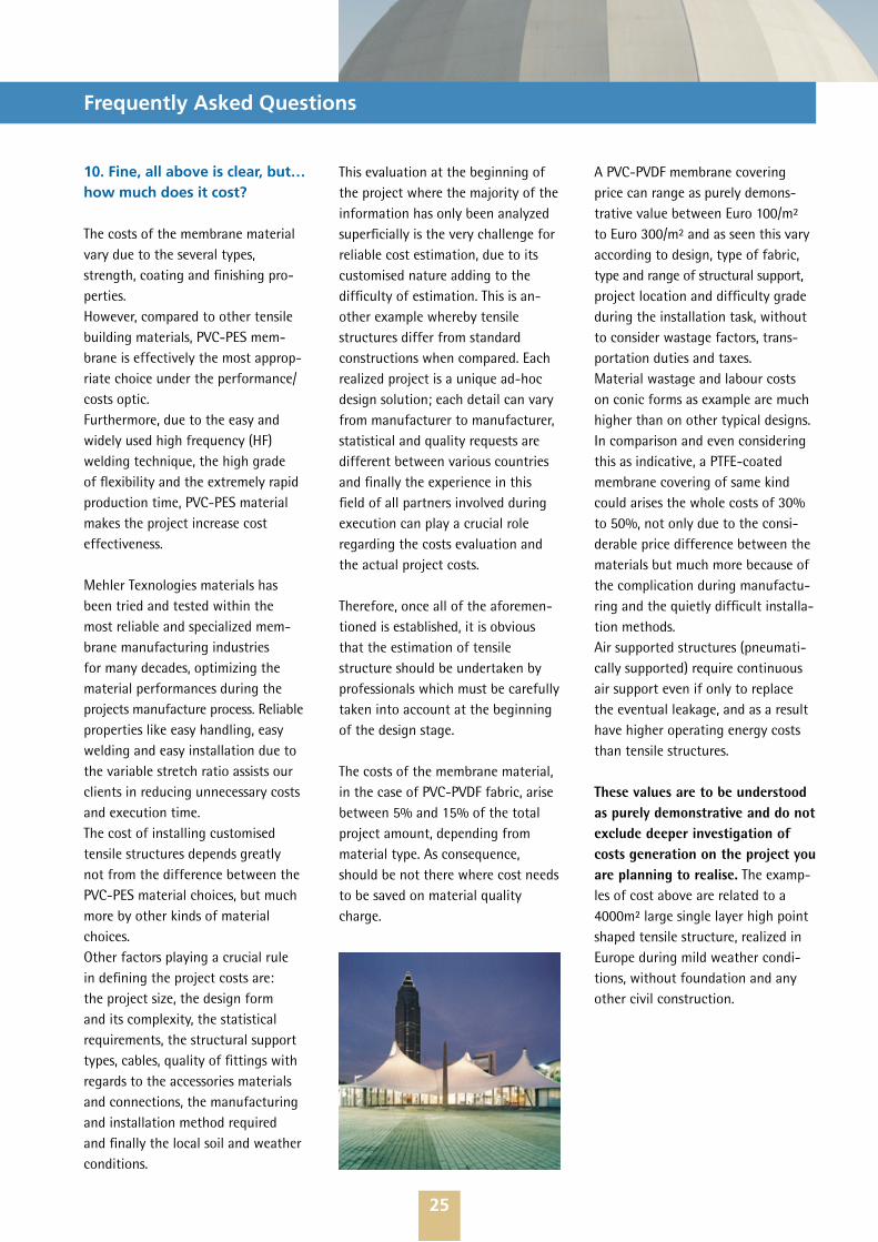
A PVC-PVDF membrane covering price can range as purely demons-trative value between Euro 100/m² to Euro 300/m² and as seen this vary according to design, type of fabric, type and range of structural support, project location and difficulty grade during the installation task, without to consider wastage factors, trans-portation duties and taxes.Material wastage and labour costs on conic forms as example are much higher than on other typical designs. In comparison and even considering this as indicative, a PTFE-coated membrane covering of same kind could arises the whole costs of 30% to 50%, not only due to the consi-derable price difference between the materials but much more because of the complication during manufactu-ring and the quietly difficult installa-tion methods. Air supported structures (pneumati-cally supported) require continuous air support even if only to replace the eventual leakage, and as a result have higher operating energy costs than tensile structures.
These values are to be understood as purely demonstrative and do not exclude deeper investigation of costs generation on the project you are planning to realise. The examp-les of cost above are related to a 4000m² large single layer high point shaped tensile structure, realized in Europe during mild weather condi-tions, without foundation and any other civil construction.
26
Frequently Asked Questions
11. OK. Last but not at least: when PVC-PES membrane − why Mehler Texnologies?
We offer our clients all our know-ledge and experience in this field. Mehler is a well-accepted pioneering Company in production of Polyester-PVC coated fabrics and holds long term experience and good relation-ships with most accredited pro-fessionals all around the world.
• For over 60 years, Mehler has continually developed innovative quality products making us a refer-ence for the whole industry
• Our organisation pro-actively preserves our environment. Our products strictly follow the Euro-pean rules and can be recycled into different products.
• We offer our high quality materials in various grades and finishes.
• Our weldable PVDF top coated ma-terial (MEHATOP F line) has more than 14 years proven in the market.
• We deliver in attractive widths of up to 5 metres (standard 2.5m).
• To reduce CO2 emission we operate warehouses around the Globe, to deliver promptly throughout the year.
• We produce 50 million square meters/year of high-quality fabric products at our 3 facilities in EU.
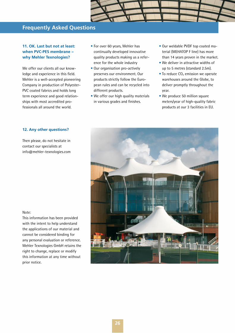
12. Any other questions?
Then please, do not hesitate in contact our specialists at [email protected]
Note: This information has been provided with the intent to help understand the applications of our material and cannot be considered binding for any personal evaluation or reference. Mehler Texnologies GmbH retains the right to change, replace or modify this information at any time without prior notice.
27
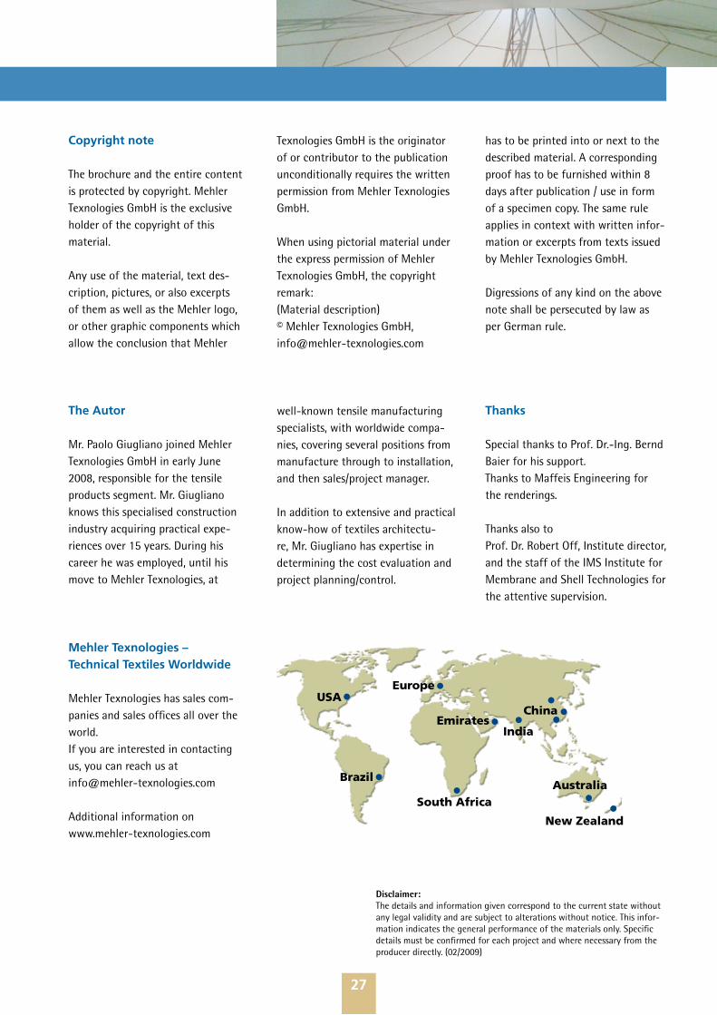
Mehler Texnologies – Technical Textiles Worldwide
Mehler Texnologies has sales com-panies and sales offices all over the world. If you are interested in contacting us, you can reach us at [email protected]
Additional information on www.mehler-texnologies.com
Copyright note
The brochure and the entire content is protected by copyright. Mehler Texnologies GmbH is the exclusive holder of the copyright of this material.
Any use of the material, text des-cription, pictures, or also excerpts of them as well as the Mehler logo, or other graphic components which allow the conclusion that Mehler
Texnologies GmbH is the originator of or contributor to the publication unconditionally requires the written permission from Mehler Texnologies GmbH.
When using pictorial material under the express permission of Mehler Texnologies GmbH, the copyright remark:(Material description) © Mehler Texnologies GmbH, [email protected]
has to be printed into or next to the described material. A corresponding proof has to be furnished within 8 days after publication / use in form of a specimen copy. The same rule applies in context with written infor-mation or excerpts from texts issued by Mehler Texnologies GmbH.
Digressions of any kind on the above note shall be persecuted by law as per German rule.
The Autor
Mr. Paolo Giugliano joined Mehler Texnologies GmbH in early June 2008, responsible for the tensile products segment. Mr. Giugliano knows this specialised construction industry acquiring practical expe-riences over 15 years. During his career he was employed, until his move to Mehler Texnologies, at
well-known tensile manufacturing specialists, with worldwide compa-nies, covering several positions from manufacture through to installation, and then sales/project manager.
In addition to extensive and practical know-how of textiles architectu-re, Mr. Giugliano has expertise in determining the cost evaluation and project planning/control.
Thanks
Special thanks to Prof. Dr.-Ing. Bernd Baier for his support.Thanks to Maffeis Engineering for the renderings.
Thanks also to Prof. Dr. Robert Off, Institute director, and the staff of the IMS Institute for Membrane and Shell Technologies for the attentive supervision.
•
••
•
• • •
• •••
EuropeUSA
Brazil
Emirates
South Africa
India
China
Australia
New Zealand
Disclaimer: The details and information given correspond to the current state without any legal validity and are subject to alterations without notice. This infor-mation indicates the general performance of the materials only. Specific details must be confirmed for each project and where necessary from the producer directly. (02/2009)
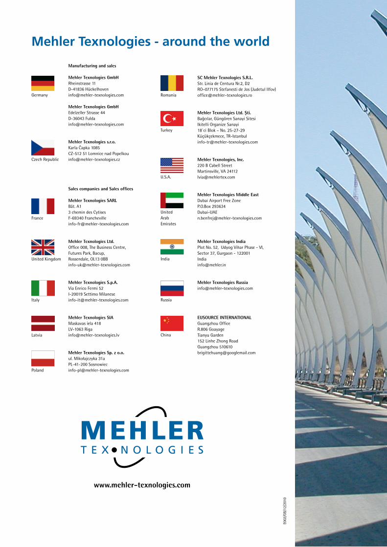
E002
/GB/
12/2
010
www.mehler-texnologies.com
Mehler Texnologies - around the world
Manufacturing and sales
Mehler Texnologies GmbHRheinstrasse 11D-41836 Hü[email protected]
Mehler Texnologies GmbHEdelzeller Strasse 44D-36043 [email protected]
Mehler Texnologies s.r.o. Karla Capka 1085 CZ-512 51 Lomnice nad Popelkou [email protected]
ˇ
Germany
Czech Republic
SC Mehler Texnologies S.R.L.Str. Linia de Centura Nr.2, D2 RO–077175 Stefanesti de Jos (Judetul Ilfov)[email protected]
Mehler Texnologies Ltd. Sti. Bagcılar, Güngören Sanayi Sitesi Ikitelli Organize Sanayi 18`ci Blok – No. 25-27-29 Küçükçekmece, TR-Istanbul [email protected]
Mehler Texnologies, Inc. 220 B Cabell Street Martinsville, VA 24112 [email protected]
Mehler Texnologies Middle EastDubai Airport Free ZoneP.O.Box [email protected]
Mehler Texnologies IndiaPlot No. 52, Udyog Vihar Phase - VI,Sector 37, Gurgaon - 122001 India [email protected]
Mehler Texnologies [email protected]
EUSOURCE INTERNATIONALGuangzhou OfficeR.806 GoayageTianyu Garden152 Linhe Zhong RoadGuangzhou [email protected]
ˆ¸
Romania
Turkey
U.S.A.
United ArabEmirates
India
Russia
China
Sales companies and Sales offices
Mehler Texnologies SARLBât. A1 3 chemin des CytisesF-69340 [email protected]
Mehler Texnologies Ltd. Office 008, The Business Centre, Futures Park, Bacup, Rossendale, OL13 [email protected]
Mehler Texnologies S.p.A. Via Enrico Fermi 52 I-20019 Settimo Milanese [email protected]
Mehler Texnologies SIA Maskavas iela 418 LV-1063 Riga [email protected]
Mehler Texnologies Sp. z o.o.ul. Mikołajczyka 31aPL-41-200 Sosnowiec [email protected]
France
United Kingdom
Italy
Latvia
Poland