technical guide aluminum light crane system - swf … · technical guide english 02/01/2017 ......
TRANSCRIPT

Original instructions, English 02/01/2017 1 / 93This document and the information contained herein, is the exclusive property of SWF Krantechnik GmbH and represents a non-public, confidential and proprietary trade secret that may not be reproduced, disclosed to third parties, altered or otherwise employed in any manner whatsoever without the express written consent of SWF Krantechnik GmbH. Copyright © (2013) SWF Krantechnik GmbH. All rights reserved.
SU
PD
OC
C2A
AA
1001
00-0
P
S22
280
2.1.
2017
TECHNICAL GUIDE
Aluminum Light Crane System
SI
SUPDOCC2AAA10-0.ORD 2.1.2017
- - - -
204949
SWF Krantechnik GmbH Postbox 310410 68264 Mannheim Germany Boehringerstraße 4 68307 Mannheim Germany tel +49(0)621 789-900 fax +49(0)621 789 90-100 [email protected] www.swfkrantechnik.com

TECHNICAL GUIDE
English 02/01/2017 2 / 93This document and the information contained herein, is the exclusive property of SWF Krantechnik GmbH and represents a non-public, confidential and proprietary trade secret that may not be reproduced,
disclosed to third parties, altered or otherwise employed in any manner whatsoever without the express written consent of SWF Krantechnik GmbH. Copyright © (2013) SWF Krantechnik GmbH. All rights
reserved.
Table of contents
1 UPDATE HISTORY ............................................................................................................................ 4
2 GENERAL INTRODUCTION .............................................................................................................. 5
2.1 About this manual ................................................................................................................................... 5
2.2 Symbols used in this manual ................................................................................................................... 5
2.3 Terminology ............................................................................................................................................ 5
2.4 About this product ................................................................................................................................... 6
2.4.1 Technical regulations .......................................................................................................................... 6
2.4.2 Safety regulations ............................................................................................................................... 7
2.4.3 Installation of light crane system .......................................................................................................... 7
2.4.4 Inspection, preventive maintenance..................................................................................................... 8
2.4.5 Other relevant documents ................................................................................................................. 10
3 PRODUCT RANGE .......................................................................................................................... 11
3.1 Environmental conditions ...................................................................................................................... 11
3.2 Aluminum crane kit at a glance ............................................................................................................. 12
3.3 Suspended cranes (downward forces) .................................................................................................. 15
3.3.1 Monorail ............................................................................................................................................ 15
3.3.2 Single girder articulated crane bridge ................................................................................................ 16
3.3.3 Single girder rigid crane bridge .......................................................................................................... 18
3.3.4 Single girder low headroom crane bridge ........................................................................................... 20
3.3.5 Double girder articulated crane bridge ............................................................................................... 22
3.3.6 Double girder rigid crane bridge ........................................................................................................ 24
3.3.7 Double girder low headroom crane bridge ......................................................................................... 26
3.4 Advanced suspended cranes ................................................................................................................ 28
3.4.1 Long outreach crane bridges ............................................................................................................. 28
3.4.2 Telescopic crane bridges................................................................................................................... 28
3.4.3 Extended cross travel crane bridges .................................................................................................. 28
3.4.4 Buffer extension and distance trolleys ............................................................................................... 28
3.4.5 Energy chain power supply ............................................................................................................... 29
4 LIGHT CRANE SYSTEM CONFIGURATION ................................................................................... 30
4.1 Selection of crane type .......................................................................................................................... 30
4.2 Quick selection ..................................................................................................................................... 31
4.3 Detailed calculation ............................................................................................................................... 42
4.3.1 Data required for calculation .............................................................................................................. 42
4.3.2 Calculating load spectrum and determining rated capacity ................................................................. 42
4.3.3 Determining rail type ......................................................................................................................... 43
4.3.4 Suspension limits and forces back to supporting structure ................................................................. 46
4.3.5 Examples of calculations ................................................................................................................... 47
4.4 Crane dimensions ................................................................................................................................. 53
4.4.1 Monorail ............................................................................................................................................ 54
4.4.2 Single girder articulated crane bridge ................................................................................................ 55
4.4.3 Single girder rigid crane bridge .......................................................................................................... 57
4.4.4 Single girder low headroom crane bridge ........................................................................................... 59
4.4.5 Double girder articulated crane bridge ............................................................................................... 61
4.4.6 Double girder rigid crane bridge ........................................................................................................ 63
4.4.7 Double girder low headroom crane bridge ......................................................................................... 65
5 CRANE COMPONENTS IN DETAIL ................................................................................................ 67
5.1 Interfaces with support steel works ........................................................................................................ 67
5.1.1 Suspension for I-beam structure ........................................................................................................ 68
5.1.2 Suspension for straight ceiling ........................................................................................................... 70
5.1.3 Bracket type suspension ................................................................................................................... 72
5.1.4 Extension sets and side supports ...................................................................................................... 74
5.2 Rail profiles ........................................................................................................................................... 76

TECHNICAL GUIDE
English 02/01/2017 3 / 93This document and the information contained herein, is the exclusive property of SWF Krantechnik GmbH and represents a non-public, confidential and proprietary trade secret that may not be reproduced,
disclosed to third parties, altered or otherwise employed in any manner whatsoever without the express written consent of SWF Krantechnik GmbH. Copyright © (2013) SWF Krantechnik GmbH. All rights
reserved.
5.3 Connection sets .................................................................................................................................... 77
5.4 End plate sets and end stops ................................................................................................................ 78
5.5 Trolleys ................................................................................................................................................. 79
5.5.1 General characteristics ...................................................................................................................... 79
5.5.2 Single push trolley ............................................................................................................................. 79
5.5.3 Double push trolley ........................................................................................................................... 81
5.5.4 Single push trolley for ATB ................................................................................................................ 82
5.5.5 Motor trolley ALTM2 .......................................................................................................................... 83
5.6 Energy supply ....................................................................................................................................... 86
5.6.1 Festoon under profile ........................................................................................................................ 86
5.6.2 Parallel enclosed conductors ............................................................................................................. 90
5.7 Electric kits for motor trolleys ................................................................................................................. 92

TECHNICAL GUIDE
English 02/01/2017 4 / 93This document and the information contained herein, is the exclusive property of SWF Krantechnik GmbH and represents a non-public, confidential and proprietary trade secret that may not be reproduced,
disclosed to third parties, altered or otherwise employed in any manner whatsoever without the express written consent of SWF Krantechnik GmbH. Copyright © (2013) SWF Krantechnik GmbH. All rights
reserved.
1 UPDATE HISTORY
Section Changes Date Handled by
All First release of the document 03/2015 XJAUHIJA
1.4.1 Group classification added 11/2015 XJAUHIJA
2.4.4 Topic title modified 11/2015 XJAUHIJA
2.4.5 New topic on energy chain power supply added 11/2015 XJAUHIJA
3.2 Abbreviation table for single girder crane bridges clarified Bridge kit references corrected throughout the tables Dimension illustrations added and modified in and above the main tables
11/2015 XJAUHIJA
3.3.2 New topic with load spectrum calculation and rated capacity determination added 11/2015 XJAUHIJA
3.3.3 Abbreviation table updated 11/2015 XJAUHIJA
3.3.4 Topic title updated, new paragraphs added, formulas modified (missing dynamic factor), other minor corrections 11/2015 XJAUHIJA
3.3.5 Load spectrum calculation added, other minor corrections 11/2015 XJAUHIJA
4.1 Text modifications in the limiting values section 11/2015 XJAUHIJA
4.1.4 Product code table modified, new paragraphs and a table at the end 11/2015 XJAUHIJA
4.5.4 New topic on single push trolley for ATB added 11/2015 XJAUHIJA
4.5.5. New paragraphs and a new note added 11/2015 XJAUHIJA
4.6.1 Text added, illustration updated to include the connection box 11/2015 XJAUHIJA
4.6.2 Small text updates 11/2015 XJAUHIJA
4.7 Illustrations updated with more details on the electric kits 11/2015 XJAUHIJA
1 Update history added, chapter numbering changed accordingly 12/2015 XJAUHIJA
General Document style and layout corrections, typo corrections 11/2016 XJAUHIJA
3.3 Corrections made to the table Compatibility matrix: track size / crane bridge size 11/2016 XJAUHIJA
3.3.4 Minimum span added 11/2016 XJAUHIJA
3.3.5 Minimum span information updated 11/2016 XJAUHIJA
3.4 Old chapter 3.4.2 Crane bridges for ATL vertical lifter removed New chapter 3.4.4 Buffer extension and distance trolleys added Chapter numbering changed accordingly
11/2016 XJAUHIJA
3.4.2 Chapter Telescopic crane bridges: a new descriptive paragraph added 11/2016 XJAUHIJA
4.1 Description of the purpose of the table clarified. Note about outreach crane type with rigid crane bridge clarified 11/2016 XJAUHIJA
4.2 New bridge kit versions added to some single and double girder articulated cranes in the quick selection table Option for 400 kg rated capacity crane removed from quick selection table
11/2016 XJAUHIJA
4.4.2 Bridge kit information updated 11/2016 XJAUHIJA
4.4.5 Bridge kit information updated 11/2016 XJAUHIJA
4.4.7 Push trolley information in the second table corrected 11/2016 XJAUHIJA
5.6.1 Information about flat cable length corrected. Information about the lockable main isolation switch and the power supply cable added Correct connection box illustration added
11/2016 XJAUHIJA
5.6.2 Information about flat cable length and conductor element length corrected 11/2016 XJAUHIJA

TECHNICAL GUIDE
English 02/01/2017 5 / 93This document and the information contained herein, is the exclusive property of SWF Krantechnik GmbH and represents a non-public, confidential and proprietary trade secret that may not be reproduced,
disclosed to third parties, altered or otherwise employed in any manner whatsoever without the express written consent of SWF Krantechnik GmbH. Copyright © (2013) SWF Krantechnik GmbH. All rights
reserved.
2 GENERAL INTRODUCTION
2.1 About this manual
This technical guide describes the aluminum light crane system product content and basic selection rules. The technical guide supports other sales tools for proper product selection. This document includes standard products available in price lists and the sales configurator, and certain special applications that require separate offer engineering.
2.2 Symbols used in this manual
The readers should familiarize themselves with the following symbols which are used in this manual.
Note : Indicates items which require special attention by the reader. There is no obvious risk of injury associated with notes.
2.3 Terminology
Light crane system Assembly of lifting equipment, crane bridges, trolleys, and tracks with their suspensions for lifting operations.
Crane bridge Aluminum profile carrying the lifting device and supported on trolleys running on tracks.
Track Stationary aluminum profiles on which a crane bridge or lifting device is running. A track consists of one or more track lines. In light crane systems, a track can be removed from the supporting building structures without influence on the strength of the supporting structures.
Suspension All necessary clamps, hanger rods, and other fittings by which a track is suspended from a building or other supporting structure.
Monorail Stationary aluminum profile on which the lifting device is running. The monorail together with a lifting device is a particular type of a light crane system.
Span Horizontal distance between the centers of the crane track rails.
Rated capacity Maximum net load that the crane is designed to lift for a given crane configuration and load location during normal operation.
Lifting device The equipment needed for lifting and lowering the load.

TECHNICAL GUIDE
English 02/01/2017 6 / 93This document and the information contained herein, is the exclusive property of SWF Krantechnik GmbH and represents a non-public, confidential and proprietary trade secret that may not be reproduced,
disclosed to third parties, altered or otherwise employed in any manner whatsoever without the express written consent of SWF Krantechnik GmbH. Copyright © (2013) SWF Krantechnik GmbH. All rights
reserved.
2.4 About this product
This product is a modular light crane system based on light-weight aluminum profiles, proposed as kits, for manual or motorized operations. The crane kits can be used to suspend different lifting devices, although this document and the quick selection tables focus on the electric chain hoist. The lifting device is excluded from the crane kit and has to be calculated separately.
The crane system is designed to be suspended from the building or a secondary steel structure, for example, a free standing system. The strength of the support structure shall be calculated by a civil engineer to ensure that it can support the forces involved when the crane is in operation. The pendular design brings only vertical downward forces to the supporting structure.
This product is typically selected because of ergonomics, light weight, modern and modular design, and easy installation.
2.4.1 Technical regulations
This state-of-the-art product has been designed and manufactured to conform to European and international standards and directives:
� European directive: 2006/42/EC
The standards and directives to which the product conforms are stated in the Declaration of Conformity or the Declaration by Manufacturer delivered with the product.
The light crane system has been designed for A4 application according to FEM1.001:1998 booklet 2: classification and loading on structures and mechanisms. Some parts of the product are designed according to EN13001.
A crane is classified on the basis of the total duration of use (number of hoisting cycles) and a load spectrum. The total duration of use is divided into utilization classes (U0 to U9). The load spectrum is also divided into classes (Q1 to Q4).
Utilization classes
Class Total duration of use
(nmax = number of hoisting cycles) U0 nmax ≤ 16 000 U1 16 000 < nmax ≤ 32 000
U2 32 000 < nmax ≤ 63 000 U3 63 000 < nmax ≤ 125 000 U4 125 000 < nmax ≤ 250 000
U5 250 000 < nmax ≤ 500 000 U6 500 000 < nmax ≤ 1 000 000 U7 1 000 000 < nmax ≤ 2 000 000 U8 2 000 000 < nmax ≤ 4 000 000
U9 4 000 000 < nmax
Load spectrum classes
Class Load spectrum factor k p
Q1 < kp ≤ 0.125 Q2 0.125 < kp ≤ 0.250
Q3 0.250 < kp ≤ 0.500 Q4 0.500 < kp 1.000

TECHNICAL GUIDE
English 02/01/2017 7 / 93This document and the information contained herein, is the exclusive property of SWF Krantechnik GmbH and represents a non-public, confidential and proprietary trade secret that may not be reproduced,
disclosed to third parties, altered or otherwise employed in any manner whatsoever without the express written consent of SWF Krantechnik GmbH. Copyright © (2013) SWF Krantechnik GmbH. All rights
reserved.
Group classification
Load spectrum class Utilization class
U0 U1 U2 U3 U4 U5 U6 U7 U8 U9
Q1 A1 A1 A1 A2 A3 A4 A5 A6 A7 A8
Q2 A1 A1 A2 A3 A4 A5 A6 A7 A8 A8
Q3 A1 A2 A3 A4 A5 A6 A7 A8 A8 A8
Q4 A2 A3 A4 A5 A6 A7 A8 A8 A8 A8
Ax Application with safety margin
A4 Acceptable application
Ax Application not acceptable
All tables in this document are given for utilization class U2 and load spectrum Q4 (Spectrum factor kp=1)
See chapter Calculating load spectrum and determining rated capacity for the calculation of the load spectrum factor kp, and chapter Examples of calculations for an example of verification of the group classification.
2.4.2 Safety regulations
This state-of-the-art product has been designed and manufactured to conform to European and international standards and directives.
� European directive: 2006/42/EC
Safety instructions for installation and operation are detailed in the installation instructions and in the operator’s manual delivered with the product. They shall be read and understood before proceeding and followed during the entire lifetime of the product.
2.4.3 Installation of light crane system
The crane shall be installed by using genuine parts supplied and/or approved by the manufacturer. Components from any other source may cause risk towards equipment or personnel and will void the warranty.
Installation instructions are provided with delivery in paper format, and can be supplied in electronic format (pdf file) under request indicating the particular order number.
Note : The installation procedure requires special skills and suitable tools to ensure safe and reliable operation of the product.
It is recommended that the installation work is carried out only by authorized service personnel or an experienced service technician authorized by the product’s manufacturer.

TECHNICAL GUIDE
English 02/01/2017 8 / 93This document and the information contained herein, is the exclusive property of SWF Krantechnik GmbH and represents a non-public, confidential and proprietary trade secret that may not be reproduced,
disclosed to third parties, altered or otherwise employed in any manner whatsoever without the express written consent of SWF Krantechnik GmbH. Copyright © (2013) SWF Krantechnik GmbH. All rights
reserved.
2.4.4 Inspection, preventive maintenance
Light crane systems and monorails are built with modular components that require low maintenance. The fixing torque of bolted connection sets shall be checked periodically, similarly as the condition of safety components and wearing parts. The correct maintenance interval depends on the actual use of the crane, minimum once a year.
Inspection intervals
Utilization Interval
Single shift usage Every 12 months Double shift usage Every 8 months
Three shift usage Every 6 months
Note : This table is a general guideline. The needed inspection interval can be shorter, depending on other factors, such as the environmental conditions. The instructions for proper maintenance are included in the (crane) Operator’s manual.

TECHNICAL GUIDE
English 02/01/2017 9 / 93This document and the information contained herein, is the exclusive property of SWF Krantechnik GmbH and represents a non-public, confidential and proprietary trade secret that may not be reproduced,
disclosed to third parties, altered or otherwise employed in any manner whatsoever without the express written consent of SWF Krantechnik GmbH. Copyright © (2013) SWF Krantechnik GmbH. All rights
reserved.
Typical (but not limited to these points) inspection points are highlighted in the following illustration:
1 Track • Condition and shape of profile • Condition of driving surface • Locking and condition of end stops and end plate sets
7 Push trolley for lifting device • Locking clip of load shaft • Condition of wheels • Rotation of guiding wheels
2 Connection set • Tightening of bolts • Contact between the profiles
8 Lifting device • Function of safety equipment (for example, limit switches) • Tightening of lifting device suspension parts • Condition and shape of load chain or rope • Lubrication of load chain or rope • Overall condition of lifting device
3 Crane bridge trolley • Locking clip of load shaft • Condition of wheels • Rotation of guiding wheels • Tightening of crane bridge suspension bolts • Condition of crane bridge suspension eye
9 Load hook • Condition and shape of load hook
4 Suspension • Safety pins • Tightening of nuts • Condition of suspension rod • Condition of upper and lower bearing parts • Shape of suspension profile
10 Pendant controller • Function and condition of push buttons • Function of emergency stop
5 Power feeding system • Condition of wheels • Fixing of cable/hose suspension • Tightening of wiring connections
11 Supporting structure • Tightening of fixing bolts • Overall condition
6 Crane bridge • Condition and shape of profile • Condition of driving surface • Locking and condition of end stops and end plate sets

TECHNICAL GUIDE
English 02/01/2017 10 / 93This document and the information contained herein, is the exclusive property of SWF Krantechnik GmbH and represents a non-public, confidential and proprietary trade secret that may not be reproduced,
disclosed to third parties, altered or otherwise employed in any manner whatsoever without the express written consent of SWF Krantechnik GmbH. Copyright © (2013) SWF Krantechnik GmbH. All rights
reserved.
2.4.5 Other relevant documents
Other documents related to the complete product selection and/or delivery are, for example:
� Crane operator’s manual � Assembly instruction for crane � Spare part catalogue � Technical guide for the selected lifting device � Owner’s manual for the selected lifting device � Installation manual for the selected lifting device � User instructions for sales configurator.

TECHNICAL GUIDE
English 02/01/2017 11 / 93This document and the information contained herein, is the exclusive property of SWF Krantechnik GmbH and represents a non-public, confidential and proprietary trade secret that may not be reproduced,
disclosed to third parties, altered or otherwise employed in any manner whatsoever without the express written consent of SWF Krantechnik GmbH. Copyright © (2013) SWF Krantechnik GmbH. All rights
reserved.
3 PRODUCT RANGE
3.1 Environmental conditions
This product is designed for indoor use in typical industrial environments. Typical customer segments are, for example, automotive industry and general manufacturing.
� Rated capacity range is up to 2000 kg.
� Temperature range is -10°C…+40°C
� Atmospheric corrosivity category is C2 according to EN ISO 12944-2.
Note : This document does not include the products for Hazardous Environments (explosive atmosphere).

TECHNICAL GUIDE
English 02/01/2017 12 / 93This document and the information contained herein, is the exclusive property of SWF Krantechnik GmbH and represents a non-public, confidential and proprietary trade secret that may not be reproduced,
disclosed to third parties, altered or otherwise employed in any manner whatsoever without the express written consent of SWF Krantechnik GmbH. Copyright © (2013) SWF Krantechnik GmbH. All rights
reserved.
3.2 Aluminum crane kit at a glance
An aluminum crane kit is built with the following components:
Pos. Component Scope of the crane kit
1 Track profile and end stops and end plate sets Yes
2 Suspension Yes
3 Connection set Yes
4 Motor trolley Yes
5 Crane bridge kit (single girder rigid in the example) Yes
6 Crane bridge profile Yes
7 Push trolley Yes
8 Lifting device No
9 Pendant controller No
10 Hook No
11 Power supply for track (flat cable in the example) Yes
12 Power supply for crane bridge (flat cable in the example) Yes

TECHNICAL GUIDE
English 02/01/2017 13 / 93This document and the information contained herein, is the exclusive property of SWF Krantechnik GmbH and represents a non-public, confidential and proprietary trade secret that may not be reproduced,
disclosed to third parties, altered or otherwise employed in any manner whatsoever without the express written consent of SWF Krantechnik GmbH. Copyright © (2013) SWF Krantechnik GmbH. All rights
reserved.
Compatibility matrix: crane system / lifting device
Crane bridge type
Single girder Double girder Monorail
Articulated Rigid Low
headroom Articulated
(*) Rigid
Low headroom Monorail
Maximum rated capacity [kg] 2000 2000 2000
2000 (1000)*
2000 2000 2000
Traveling motors
Lifting device OK OK OK OK
(n/a)* OK OK OK
Crane bridge n/a OK OK n/a
(n/a)* OK OK n/a
Lifting device
ECH OK OK OK OK
(option)* OK OK OK
ATB OK OK OK Option
(option)* Option Option OK
HCB OK OK OK Option
(option)* Option Option OK
BH Option Option Option Option
(option)* Option Option Option
*Articulated plate trolleys.
Abbreviations
ECH Electric chain hoist
ATB Air balancer HCB Hand chain block (manual lifting equipment) BH Belt hoist OK Available as standard
n/a Not available Option Special arrangement with the Sales Support team

TECHNICAL GUIDE
English 02/01/2017 14 / 93This document and the information contained herein, is the exclusive property of SWF Krantechnik GmbH and represents a non-public, confidential and proprietary trade secret that may not be reproduced,
disclosed to third parties, altered or otherwise employed in any manner whatsoever without the express written consent of SWF Krantechnik GmbH. Copyright © (2013) SWF Krantechnik GmbH. All rights
reserved.
Compatibility matrix: track size / crane bridge siz e
Crane bridge profile Crane bridge
traveling motor
Crane bridge power supply (along the track)
AL06 AL08 AL10 AL14 ALTM2 Festoon Enclosed conductor lines 1)
Cable support
Hose support
Akapp RC4
Vahle KBH2)
Vahle MKH2)
Track profile
AL06 OK OK OK OK n/a OK OK n/a OK n/a AL08 OK OK OK OK n/a OK OK n/a OK n/a
AL10 OK OK OK OK OK OK OK OK OK OK AL14 OK OK OK OK OK OK OK OK OK OK
Lifting device travel motor
ALTM2 n/a n/a OK OK
Lifting device power supply (along the crane bridge)
Festoon cable support OK OK OK OK
Festoon hose support OK OK OK OK
RC4/RC7 n/a n/a OK OK
MKH n/a n/a OK OK
KBH OK OK OK OK
1)For details on enclosed conductor lines, see chapter Parallel enclosed conductors.
2)The KBH and MKH products are available as options. Contact Sales Support team.

TECHNICAL GUIDE
English 02/01/2017 15 / 93This document and the information contained herein, is the exclusive property of SWF Krantechnik GmbH and represents a non-public, confidential and proprietary trade secret that may not be reproduced,
disclosed to third parties, altered or otherwise employed in any manner whatsoever without the express written consent of SWF Krantechnik GmbH. Copyright © (2013) SWF Krantechnik GmbH. All rights
reserved.
3.3 Suspended cranes (downward forces)
The cranes and monorails have typically only downward forces. With a telescopic construction, or a combination of long outreach, high capacity, short span, and/or integration of torque (vertical lifter), it is possible that also upward forces occur. This document covers the downward forces. For information about the upward forces, contact the Sales Support team.
3.3.1 Monorail
A monorail crane is used for linear transport of material. Restrictions in the lateral movement of some lifting devices can cause side-pulling. If a lateral movement beyond the limitations is required, for example, for assembly type of work, a more suitable girder crane type can be selected instead.
The length of a monorail is limited by the power supply and heat expansion; the maximum value is set at 100 m for the standard application.
For information on the optional double monorail configuration, contact the Sales Support team.
Pos. Part Description
1 Monorail track The lifting device moves along the monorail track.
2 Connection set The track segments are connected to each other to form the track.
3 Suspension The crane can be suspended off the ceiling or other overhead structure from support brackets.
4 Motor trolley The motor trolley is used where motorized movement of the lifting device is required.
5 Push trolley The lifting device is mounted on trolleys which run inside the track profile.
6 Lifting device The lifting device lifts and lowers the load.
7 Hook The hook is used to attach the load for lifting.
8 Pendant controller The lifting device is operated using the pendant controller.
9 Power feeding system The power feeding systems supplies power to the lifting device and motor trolley (if equipped).

TECHNICAL GUIDE
English 02/01/2017 16 / 93This document and the information contained herein, is the exclusive property of SWF Krantechnik GmbH and represents a non-public, confidential and proprietary trade secret that may not be reproduced,
disclosed to third parties, altered or otherwise employed in any manner whatsoever without the express written consent of SWF Krantechnik GmbH. Copyright © (2013) SWF Krantechnik GmbH. All rights
reserved.
3.3.2 Single girder articulated crane bridge
The girder cranes are used for two-dimensional traveling. The articulated crane is recommended for manually operated crane bridge motions.
The cranes with a single girder articulated crane bridge are very light and efficient tools for assembly work with manual movement. The crane bridge suspension allows the crane bridge to skew while pulling it along the track, which, combined with the lowest dead weight, reduces efforts to move the load.
The articulated crane construction does not allow traveling motors for crane bridge travel, but a rigid or low headroom construction can be used instead.
If the crane span is more than 6 m, the increased skewing effect can affect the performance of the crane.
Pos. Part Description
1 Connection set The profiles are connected to each other to form the track.
2 Suspension The crane can be suspended off the ceiling or other overhead structure from support brackets.
3 Track An overhead track is made up of profiles and is used for the crane bridge to move along its length.
4 Crane bridge trolley The crane bridge is mounted on trolleys which run inside the track profile.
5 Power feeding system The power feeding systems supplies power to the lifting device and motor trolley (if equipped).
6 Lifting device The lifting device lifts and lowers the load.
7 Push trolley The lifting device is mounted on trolleys which run inside the crane bridge profile.
8 Crane bridge The crane bridge is also made up of profiles and is used for the lifting device to move along its length.
9 Pendant controller The crane is operated using the pendant controller.
10 Hook The hook is used to attach the load for lifting.

TECHNICAL GUIDE
English 02/01/2017 17 / 93This document and the information contained herein, is the exclusive property of SWF Krantechnik GmbH and represents a non-public, confidential and proprietary trade secret that may not be reproduced,
disclosed to third parties, altered or otherwise employed in any manner whatsoever without the express written consent of SWF Krantechnik GmbH. Copyright © (2013) SWF Krantechnik GmbH. All rights
reserved.
Bridge kit contents
• Push trolleys (2) • Bridge suspensions (2) • End plate sets (2) Note : Profiles are not included in the bridge kit, they are selected separately.

TECHNICAL GUIDE
English 02/01/2017 18 / 93This document and the information contained herein, is the exclusive property of SWF Krantechnik GmbH and represents a non-public, confidential and proprietary trade secret that may not be reproduced,
disclosed to third parties, altered or otherwise employed in any manner whatsoever without the express written consent of SWF Krantechnik GmbH. Copyright © (2013) SWF Krantechnik GmbH. All rights
reserved.
3.3.3 Single girder rigid crane bridge
The cranes with a single girder rigid crane bridge are suitable for both manual and motorized use. The triangle pieces keep the crane bridge always fully perpendicular to the track, and allow for a crane bridge length up to 8 m (maximum length of the aluminum profile). As the recommended solution for the motorized crane bridge motion, the single girder rigid crane bridge is available as the AL10 and AL14 profiles. To optimize the bridge approach, the crane bridge motor trolleys can be installed inside the triangle plates.
Due to the size of the triangle pieces, the minimum span is 2 m.
Pos. Part Description
1 Track An overhead track is made up of profiles and is used for the crane bridge to move along its length.
2 Suspension The crane can be suspended off the ceiling or other overhead structure from support brackets.
3 Connection set The profiles are connected to each other to form the tracks.
4 Crane bridge trolley The crane bridge is mounted on trolleys which run inside the track profiles.
5 Motor trolley The motor trolley is used where horizontal motorized movement of the crane bridge or lifting device is required.
6 Crane bridge The crane bridge is also made up of profiles and is used for the lifting device to move along its length.
7 Push trolley The lifting device is mounted on trolleys which run inside the crane bridge profile.
8 Lifting device The lifting device lifts and lowers the load.
9 Pendant controller The crane is operated using the pendant controller.
10 Hook The hook is used to attach the load for lifting.
11 Power feeding system The power feeding systems supplies power to the lifting device and motor trolley (if equipped).

TECHNICAL GUIDE
English 02/01/2017 19 / 93This document and the information contained herein, is the exclusive property of SWF Krantechnik GmbH and represents a non-public, confidential and proprietary trade secret that may not be reproduced,
disclosed to third parties, altered or otherwise employed in any manner whatsoever without the express written consent of SWF Krantechnik GmbH. Copyright © (2013) SWF Krantechnik GmbH. All rights
reserved.
Bridge kit contents
• Push trolleys (4) • Triangle kits (2) • End plate sets (2) Note : Profiles are not included in the bridge kit, they are selected separately.

TECHNICAL GUIDE
English 02/01/2017 20 / 93This document and the information contained herein, is the exclusive property of SWF Krantechnik GmbH and represents a non-public, confidential and proprietary trade secret that may not be reproduced,
disclosed to third parties, altered or otherwise employed in any manner whatsoever without the express written consent of SWF Krantechnik GmbH. Copyright © (2013) SWF Krantechnik GmbH. All rights
reserved.
3.3.4 Single girder low headroom crane bridge
The low headroom construction reduces the total height of the system significantly, and therefore increases the hook stroke. The low headroom construction keeps the crane bridge always fully perpendicular to the track, and prevents any skewing effect. It also allows for longer spans than the articulated or rigid ones. In this configuration, there is no crane bridge outreach.
The minimum span is 1000 mm.
Pos. Part Description
1 Track An overhead track is made up of profiles and is used for the crane bridge to move along its length.
2 Suspension The crane can be suspended off the ceiling or other overhead structure from support brackets.
3 Connection set The profiles are connected to each other to form the tracks.
4 Crane bridge trolley The crane bridge is mounted on trolleys which run inside the track profiles.
5 Power feeding system The power feeding systems supplies power to the lifting device and motor trolley (if equipped).
6 Push trolley The lifting device is mounted on trolleys which run inside the crane bridge profile.
7 Lifting device The lifting device lifts and lowers the load.
8 Crane bridge The crane bridge is also made up of profiles and is used for the lifting device to move along its length.
9 Pendant controller The crane is operated using the pendant controller.
10 Hook The hook is used to attach the load for lifting.
11 Motor trolley The motor trolley is used where horizontal motorized movement of the crane bridge or lifting device is required.

TECHNICAL GUIDE
English 02/01/2017 21 / 93This document and the information contained herein, is the exclusive property of SWF Krantechnik GmbH and represents a non-public, confidential and proprietary trade secret that may not be reproduced,
disclosed to third parties, altered or otherwise employed in any manner whatsoever without the express written consent of SWF Krantechnik GmbH. Copyright © (2013) SWF Krantechnik GmbH. All rights
reserved.
Bridge kit contents
• Push trolleys (4) • Low headroom supports (2) Note : Profiles are not included in the bridge kit, they are selected separately.

TECHNICAL GUIDE
English 02/01/2017 22 / 93This document and the information contained herein, is the exclusive property of SWF Krantechnik GmbH and represents a non-public, confidential and proprietary trade secret that may not be reproduced,
disclosed to third parties, altered or otherwise employed in any manner whatsoever without the express written consent of SWF Krantechnik GmbH. Copyright © (2013) SWF Krantechnik GmbH. All rights
reserved.
3.3.5 Double girder articulated crane bridge
A crane with a double girder articulated crane bridge allows for a longer span and/or higher loads than a single girder crane. It also provides improved headroom as the push trolley is located between the girders. The articulated crane is recommended for manually operated crane bridge motions.
The maximum length of the crane bridge is limited by the load, the B dimension of the crane bridge profile, or the outreach. Only one connection per crane bridge profile is allowed.
The recommended minimum span is 600 mm for the AL06 and AL08 crane bridges and 700 mm for the AL10 and AL14 crane bridges.
Pos. Part Description
1 Power feeding system The power feeding systems supplies power to the lifting device and motor trolley (if equipped).
2 Track An overhead track is made up of profiles and is used for the crane bridge to move along its length.
3 Suspension The crane can be suspended off the ceiling or other overhead structure from support brackets.
4 Connection set The profiles are connected to each other to form the track or crane bridge.
5 Crane bridge trolley The crane bridge is mounted on trolleys which run inside the track profiles.
6 Crane bridge The crane bridge is also made up of profiles and is used for the lifting device to move along its length.
7 Push trolley The lifting device is mounted on trolleys which run inside the crane bridge profile.
8 Lifting device The lifting device lifts and lowers the load.
9 Pendant controller The crane is operated using the pendant controller.
10 Hook The hook is used to attach the load for lifting.
11 Motor trolley The motor trolley is used where motorized movement of the crane bridge or lifting device is required.

TECHNICAL GUIDE
English 02/01/2017 23 / 93This document and the information contained herein, is the exclusive property of SWF Krantechnik GmbH and represents a non-public, confidential and proprietary trade secret that may not be reproduced,
disclosed to third parties, altered or otherwise employed in any manner whatsoever without the express written consent of SWF Krantechnik GmbH. Copyright © (2013) SWF Krantechnik GmbH. All rights
reserved.
Bridge kit contents
• Push trolleys (4) • Bridge suspensions (4) • Connection beams (2) • End plate sets (4) Note : Profiles are not included in the bridge kit, they are selected separately.

TECHNICAL GUIDE
English 02/01/2017 24 / 93This document and the information contained herein, is the exclusive property of SWF Krantechnik GmbH and represents a non-public, confidential and proprietary trade secret that may not be reproduced,
disclosed to third parties, altered or otherwise employed in any manner whatsoever without the express written consent of SWF Krantechnik GmbH. Copyright © (2013) SWF Krantechnik GmbH. All rights
reserved.
3.3.6 Double girder rigid crane bridge
A crane with a double girder rigid crane bridge is suitable for both manual and motorized use. The triangle pieces keep the crane bridge always fully perpendicular to the track. As the recommended solution for motorized crane bridge motion, the double girder rigid crane bridge is available as the AL10 and AL14 profiles. To optimize the bridge approach, the crane bridge motor trolleys can be installed inside the triangle plates.
Due to the size of the triangle pieces, the minimum span is 2 m.
The maximum length of the crane bridge is limited by the load, the B dimension of the crane bridge profile, or the outreach. Only one connection per crane bridge profile is allowed.
Pos. Part Description
1 Power feeding system The power feeding systems supplies power to the lifting device and motor trolley (if equipped).
2 Track An overhead track is made up of profiles and is used for the crane bridge to move along its length.
3 Suspension The crane can be suspended off the ceiling or other overhead structure from support brackets.
4 Connection set The profiles are connected to each other to form the track or crane bridge.
5 Crane bridge trolley The crane bridge is mounted on trolleys which run inside the track profile.
6 Crane bridge The crane bridge is also made up of profiles and is used for the lifting device to move along its length.
7 Push trolley The lifting device is mounted on trolleys which run inside the crane bridge profile.
8 Lifting device The lifting device lifts and lowers the load.
9 Hook The hook is used to attach the load for lifting.
10 Pendant controller The crane is operated using the pendant controller.
11 Motor trolley The motor trolley is used where motorized movement of the crane bridge or lifting device is required.

TECHNICAL GUIDE
English 02/01/2017 25 / 93This document and the information contained herein, is the exclusive property of SWF Krantechnik GmbH and represents a non-public, confidential and proprietary trade secret that may not be reproduced,
disclosed to third parties, altered or otherwise employed in any manner whatsoever without the express written consent of SWF Krantechnik GmbH. Copyright © (2013) SWF Krantechnik GmbH. All rights
reserved.
Bridge kit contents
• Push trolleys (4) • Triangle kits (2) • End plate sets (4) Note : Profiles are not included in the bridge kit, they are selected separately.

TECHNICAL GUIDE
English 02/01/2017 26 / 93This document and the information contained herein, is the exclusive property of SWF Krantechnik GmbH and represents a non-public, confidential and proprietary trade secret that may not be reproduced,
disclosed to third parties, altered or otherwise employed in any manner whatsoever without the express written consent of SWF Krantechnik GmbH. Copyright © (2013) SWF Krantechnik GmbH. All rights
reserved.
3.3.7 Double girder low headroom crane bridge
The double girder low headroom crane bridge is is the most compact crane solution, providing a very low headroom and the maximum possible hook stroke.
The low headroom construction allows for longer spans than the articulated or rigid ones. In this configuration, there is no crane bridge outreach.
The minimum span is 1000 mm.
Pos. Part Description
1 Power feeding system The power feeding systems supplies power to the lifting device and motor trolley (if equipped).
2 Track An overhead track is made up of profiles and is used for the crane bridge to move along its length.
3 Suspension The crane can be suspended off the ceiling or other overhead structure from support brackets.
4 Connection set The profiles are connected to each other to form the track or crane bridge.
5 Crane bridge trolley The crane bridge is mounted on trolleys which run inside the track profile.
6 Crane bridge The crane bridge is also made up of profiles and is used for the lifting device to move along its length.
7 Push trolley The lifting device is mounted on trolleys which run inside the crane bridge profile.
8 Lifting device The lifting device lifts and lowers the load.
9 Hook The hook is used to attach the load for lifting.
10 Pendant controller The crane is operated using the pendant controller.
11 Motor trolley The motor trolley is used where motorized movement of the crane bridge or lifting device is required.

TECHNICAL GUIDE
English 02/01/2017 27 / 93This document and the information contained herein, is the exclusive property of SWF Krantechnik GmbH and represents a non-public, confidential and proprietary trade secret that may not be reproduced,
disclosed to third parties, altered or otherwise employed in any manner whatsoever without the express written consent of SWF Krantechnik GmbH. Copyright © (2013) SWF Krantechnik GmbH. All rights
reserved.
Bridge kit contents
• Push trolleys (4) • Low headroom supports (2) Note : Profiles are not included in the bridge kit, they are selected separately.

TECHNICAL GUIDE
English 02/01/2017 28 / 93This document and the information contained herein, is the exclusive property of SWF Krantechnik GmbH and represents a non-public, confidential and proprietary trade secret that may not be reproduced,
disclosed to third parties, altered or otherwise employed in any manner whatsoever without the express written consent of SWF Krantechnik GmbH. Copyright © (2013) SWF Krantechnik GmbH. All rights
reserved.
3.4 Advanced suspended cranes
3.4.1 Long outreach crane bridges
Due to its light weight, the aluminum crane bridge loses balance when the load is suspended outside of the track. However, it is possible to extend the girder of articulated and rigid crane bridges for festoon storage area. This possibility is limited by the maximal length of the profiles, as no connection is allowed on single girder crane bridges.
For more information about this option, contact the Sales Support team.
3.4.2 Telescopic crane bridges
The telescopic crane allows a greater outreach through a second girder moving under the main girder crane. This solution can be required when it is not possible to place the track above the lifting or lowering position of the load. The purpose of the solution is to lift or lower the load out of the span. The load must be moved inside the span area to allow a long travel.
For more information about this option, contact the Sales Support team.
3.4.3 Extended cross travel crane bridges
When very long travel is required for the crane bridge, specific arrangements with three tracks are possible. In this case, rigid motorized crane bridges are mandatory.
For more information about this option, contact the Sales Support team.
3.4.4 Buffer extension and distance trolleys
In a light crane system with multiple crane bridges, it may be necessary ensure a minimum distance between bridges. This is done to prevent collisions between hoists and to avoid overloading the track and suspensions. Predefined buffer extensions and distance trolleys allow for modularity and easy installation without impairing the ability of the crane bridges to cover the largest possible area.
For more information about this option, contact the Sales Support team.

TECHNICAL GUIDE
English 02/01/2017 29 / 93This document and the information contained herein, is the exclusive property of SWF Krantechnik GmbH and represents a non-public, confidential and proprietary trade secret that may not be reproduced,
disclosed to third parties, altered or otherwise employed in any manner whatsoever without the express written consent of SWF Krantechnik GmbH. Copyright © (2013) SWF Krantechnik GmbH. All rights
reserved.
3.4.5 Energy chain power supply
The standard power supply method is either the festoon cable under the profile or the parallel enclosed conductor line. As an option, the power supply can be provided with the energy chain beside the profile.
For more information about this option, contact the Sales Support team.

TECHNICAL GUIDE
English 02/01/2017 30 / 93This document and the information contained herein, is the exclusive property of SWF Krantechnik GmbH and represents a non-public, confidential and proprietary trade secret that may not be reproduced,
disclosed to third parties, altered or otherwise employed in any manner whatsoever without the express written consent of SWF Krantechnik GmbH. Copyright © (2013) SWF Krantechnik GmbH. All rights
reserved.
4 LIGHT CRANE SYSTEM CONFIGURATION
4.1 Selection of crane type
The following table summarizes the main criteria to take into account when selecting the crane type and crane bridge construction:
Selection criteria Single girder crane bridge Double girder crane bridge
Monorail Articulated Rigid Low
headroom Articulated Rigid Low
headroom
Transportation method
Linear + + + + + + ++
2-dimensional ++ ++ ++ ++ ++ ++ n/a
Rated capacity [kg]
63–1250 ++ ++ ++ + + + ++
1250–2000 + + + ++ ++ ++ +
Span < 6 m ++ + + + + + n/a
> 6 m + ++ + + + + n/a
Position of load on crane bridge during crane bridge travel
In between track profiles ++ + + + + + n/a
In outreach area + ++1) n/a + ++ n/a n/a
Limited height n/a n/a ++ + + ++ n/a
1)Especially, when the parallel enclosed conductors are used along the track, to optimize the movements of the crane bridge.
Explanations
++ Recommended
+ Possible
n/a Not applicable

TECHNICAL GUIDE
English 02/01/2017 31 / 93This document and the information contained herein, is the exclusive property of SWF Krantechnik GmbH and represents a non-public, confidential and proprietary trade secret that may not be reproduced,
disclosed to third parties, altered or otherwise employed in any manner whatsoever without the express written consent of SWF Krantechnik GmbH. Copyright © (2013) SWF Krantechnik GmbH. All rights
reserved.
4.2 Quick selection
The quick selection helps to determine quickly the required profile sizes for the crane.
Note : The results of the quick selection must be evaluated with the sales configurator.
Note : The quick selection tables and the graphs for determining the rail type do not take into account an outreach that is longer than 100 mm. This means that the load is always located between the track profiles.
The outreach can be extended, for example, for storing the festoon trolleys. See chapter Festoon under profile for the calculation of the number of the festoon trolleys required.
For longer load-supporting outreaches, contact the Sales Support team.
Note : For limitations on the hook approach, see the following chapters of this document:
• Chapter Crane dimensions for the minimum distance between the hook and the end of the rail.
• Chapter Energy supply for the details regarding the space requirements for the energy supply.
A predetermined lifting device weight has been taken into account when the measurements were calculated. If a different lifting device weight or crane span is needed, the detailed calculations in the following chapter must be executed.
All given values are maximum values, and are given in millimeters (mm). The deflection criteria used is L/500.
The quick selection tables and graphs are applicable to single bridge configurations. For configurations with multiple bridges, contact the Sales Support team.

TECHNICAL GUIDE
English 02/01/2017 32 / 93This document and the information contained herein, is the exclusive property of SWF Krantechnik GmbH and represents a non-public, confidential and proprietary trade secret that may not be reproduced,
disclosed to third parties, altered or otherwise employed in any manner whatsoever without the express written consent of SWF Krantechnik GmbH. Copyright © (2013) SWF Krantechnik GmbH. All rights
reserved.
Single girder crane bridges
The following abbreviations are used in the quick selection table:
Lmax Span: maximum distance between tracks
Amax Maximum distance between suspensions on the track
H1
H1 = HT + HB HT Height of track (between top of track profile and top of crane bridge profile) HB Height of the crane bridge/monorail (between top of crane bridge / monorail profile and top of push trolley bolt)

TECHNICAL GUIDE
English 02/01/2017 33 / 93This document and the information contained herein, is the exclusive property of SWF Krantechnik GmbH and represents a non-public, confidential and proprietary trade secret that may not be reproduced,
disclosed to third parties, altered or otherwise employed in any manner whatsoever without the express written consent of SWF Krantechnik GmbH. Copyright © (2013) SWF Krantechnik GmbH. All rights
reserved.
Single girder articulated Single girder rigid Single girder low headroom
Crane bridge Track Crane bridge Track Crane bridge Track
L max. Profile A
max. Profile Bridge kit H1 L max. Profile A
max. Profile Bridge kit H1 L max. Profile A
max. Profile Bridge kit H1
Rated capacity 63 kg, lifting device weight 30 kg
5390 AL06
4970 AL06 AL06B110 405.5
n/a
5590 AL06
4830 AL06 AL06B160 174.5
7360 AL08 AL06B110 455.5 7190 AL08 AL06B160 224.5
8000 AL10 AL06B115 498 8000 AL10 AL06B165 267
8000 AL14 AL06B115 529 8000 AL14 AL06B165 298
7800 AL08
4710 AL06 AL08B110 455
8070 AL08
4520 AL06 AL08B160 180
7040 AL08 AL08B110 505 6780 AL08 AL08B160 230
8000 AL10 AL08B115 547.5 8000 AL10 AL08B165 272.5
8000 AL14 AL08B115 578.5 8000 AL14 AL08B165 303.5
7800 AL10 8000 AL10 AL10B110 590.5
7800 AL10 7820 AL10 AL10B130 600.5
8200 AL10 7800 AL10 AL10B160 270.5
8000 AL14 AL10B110 621.5 8000 AL14 AL10B130 631.5 8000 AL14 AL10B160 301.5
7800 AL14 7850 AL10 AL14B110 621.5
7800 AL14 7590 AL10 AL14B130 631.5
8200 AL14 7570 AL10 AL14B160 271.5
8000 AL14 AL14B110 652.5 8000 AL14 AL14B130 662.5 8000 AL14 AL14B160 302.5
Rated capacity 80 kg, lifting device weight 30 kg
5060 AL06
4720 AL06 AL06B110 405.5
n/a
5260 AL06
4620 AL06 AL06B160 174.5
7050 AL08 AL06B110 455.5 6910 AL08 AL06B160 224.5
8000 AL10 AL06B115 498 8000 AL10 AL06B165 267
8000 AL14 AL06B115 529 8000 AL14 AL06B165 298
7480 AL08
4500 AL06 AL08B110 455
7680 AL08
4340 AL06 AL08B160 180
6770 AL08 AL08B110 505 6550 AL08 AL08B160 230
8000 AL10 AL08B115 547.5 7790 AL10 AL08B165 272.5
8000 AL14 AL08B115 578.5 8000 AL14 AL08B165 303.5
7800 AL10
4340 AL06 AL10B115 498 n/a
6550 AL08 AL10B115 548
7820 AL10 AL10B110 590.5 7800 AL10
7560 AL10 AL10B130 600.5 8200 AL10
7550 AL10 AL10B160 270.5
8000 AL14 AL10B110 621.5 8000 AL14 AL10B130 631.5 8000 AL14 AL10B160 301.5
7800 AL14
4170 AL06 AL14B115 529 n/a n/a
6330 AL08 AL14B115 579
7590 AL10 AL14B110 621.5 7800 AL14
7350 AL10 AL14B130 631.5 8200 AL14
7340 AL10 AL14B160 271.5
8000 AL14 AL14B110 652.5 8000 AL14 AL14B130 662.5 8000 AL14 AL14B160 302.5
Rated capacity 125 kg, lifting device weight 30 kg
4410 AL06
4200 AL06 AL06B110 405.5
n/a
4610 AL06
4150 AL06 AL06B160 174.5
6370 AL08 AL06B110 455.5 6300 AL08 AL06B160 224.5
7600 AL10 AL06B115 498 7520 AL10 AL06B165 267
8000 AL14 AL06B115 529 8000 AL14 AL06B165 298
6650 AL08
4050 AL06 AL08B110 455
6850 AL08
3950 AL06 AL08B160 180
6170 AL08 AL08B110 505 6020 AL08 AL08B160 230
7380 AL10 AL08B115 547.5 7220 AL10 AL08B165 272.5
8000 AL14 AL08B115 578.5 8000 AL14 AL08B165 303.5
7800 AL10
3900 AL06 AL10B115 498 n/a
5950 AL08 AL10B115 548
7180 AL10 AL10B110 590.5 7800 AL10
6980 AL10 AL10B130 600.5 8120 AL10
6980 AL10 AL10B160 270.5
8000 AL14 AL10B110 621.5 8000 AL14 AL10B130 631.5 8000 AL14 AL10B160 301.5
7800 AL14
3780 AL06 AL14B115
529
n/a n/a 5790 AL08
AL14B115 579
7000 AL10 AL14B110 621.5 7800 AL14
6810 AL10 AL14B130 631.5 8200 AL14
6810 AL10 AL14B160 271.5
8000 AL14 AL14B110 652.5 8000 AL14 AL14B130 662.5 8000 AL14 AL14B160 302.5

TECHNICAL GUIDE
English 02/01/2017 34 / 93This document and the information contained herein, is the exclusive property of SWF Krantechnik GmbH and represents a non-public, confidential and proprietary trade secret that may not be reproduced,
disclosed to third parties, altered or otherwise employed in any manner whatsoever without the express written consent of SWF Krantechnik GmbH. Copyright © (2013) SWF Krantechnik GmbH. All rights
reserved.
Single girder articulated Single girder rigid Single girder low headroom
Crane bridge Track Crane bridge Track Crane bridge Track
L max. Profile A
max. Profile Bridge kit H1 L max. Profile A
max. Profile Bridge kit H1 L max. Profile A
max. Profile Bridge kit H1
Rated capacity 160 kg, lifting device weight 30 kg
4040 AL06
3890 AL06 AL06B110 405.5
n/a
4240 AL06
3870 AL06 AL06B160 174.5
5940 AL08 AL06B110 455.5 5910 AL08 AL06B160 224.5
7140 AL10 AL06B115 498 7110 AL10 AL06B165 267
8000 AL14 AL06B115 529 8000 AL14 AL06B165 298
6150 AL08
3780 AL06 AL08B110 455
6350 AL08
3700 AL06 AL08B160 180
5790 AL08 AL08B110 505 5680 AL08 AL08B160 230
6970 AL10 AL08B115 547.5 6850 AL10 AL08B165 272.5
8000 AL14 AL08B115 578.5 8000 AL14 AL08B165 303.5
7400 AL10
3650 AL06 AL10B115 498 n/a
5610 AL08 AL10B115 548
6800 AL10 AL10B110 590.5 7400 AL10
6620 AL10 AL10B130 600.5 7600 AL10
6640 AL10 AL10B160 270.5
8000 AL14 AL10B110 621.5 8000 AL14 AL10B130 631.5 8000 AL14 AL10B160 301.5
7800 AL14
3540 AL06 AL14B115 529 n/a n/a
5440 AL08 AL14B115 579
6620 AL10 AL14B110 621.5 7800 AL14
6450 AL10 AL14B130 631.5 8200 AL14
6460 AL10 AL14B160 271.5
8000 AL14 AL14B110 652.5 8000 AL14 AL14B130 662.5 8000 AL14 AL14B160 302.5
Rated capacity 250 kg, lifting device weight 30 kg
3390 AL06
3320 AL06 AL06B110 405.5
n/a
3590 AL06
3340 AL06 AL06B160 174.5
5130 AL08 AL06B110 455.5 5160 AL08 AL06B160 224.5
6240 AL10 AL06B115 498 6270 AL10 AL06B165 267
7900 AL14 AL06B115 529 7930 AL14 AL06B165 298
5240 AL08
3250 AL06 AL08B110 455
5440 AL08
3220 AL06 AL08B160 180
5040 AL08 AL08B110 505 4990 AL08 AL08B160 230
6140 AL10 AL08B115 547.5 6080 AL10 AL08B165 272.5
7770 AL14 AL08B115 578.5 7720 AL14 AL08B165 303.5
6380 AL10
3180 AL06 AL10B115 498 n/a
4930 AL08 AL10B115 548
6030 AL10 AL10B110 590.5 6380 AL10
5900 AL10 AL10B130 600.5 6580 AL10
5940 AL10 AL10B160 270.5
7650 AL14 AL10B110 621.5 7500 AL14 AL10B130 631.5 7550 AL14 AL10B160 301.5
7800 AL14
3080 AL06 AL14B115 529 n/a n/a
4780 AL08 AL14B115 579
5850 AL10 AL14B110 621.5 7800 AL14
5740 AL10 AL14B130 631.5 8200 AL14
5760 AL10 AL14B160 271.5
7450 AL14 AL14B110 652.5 7320 AL14 AL14B130 662.5 7340 AL14 AL14B160 302.5
Rated capacity 320 kg, lifting device weight 35 kg
3040 AL06
2990 AL06 AL06B110 405.5
n/a
3240 AL06
3030 AL06 AL06B160 174.5
4650 AL08 AL06B110 455.5 4710 AL08 AL06B160 224.5
5690 AL10 AL06B115 498 5760 AL10 AL06B165 267
7270 AL14 AL06B115 529 7350 AL14 AL06B165 298
4720 AL08
2950 AL06 AL08B110 455
4920 AL08
2940 AL06 AL08B160 180
4590 AL08 AL08B110 505 4570 AL08 AL08B160 230
5620 AL10 AL08B115 547.5 5600 AL10 AL08B165 272.5
7180 AL14 AL08B115 578.5 7160 AL14 AL08B165 303.5
5790 AL10
2890 AL06 AL10B115 498 n/a
4510 AL08 AL10B115 548
5540 AL10 AL10B110 590.5 5790 AL10
5440 AL10 AL10B130 600.5 5990 AL10
5490 AL10 AL10B160 270.5
7080 AL14 AL10B110 621.5 6970 AL14 AL10B130 631.5 7030 AL14 AL10B160 301.5
7370 AL14
2810 AL06 AL14B115 529
4390 AL08 AL14B115 579
5400 AL10 AL14B110 621.5 7370 AL14
5310 AL10 AL14B130 631.5 7570 AL14
5350 AL10 AL14B160 271.5
6920 AL14 AL14B110 652.5 6810 AL14 AL14B130 662.5 6860 AL14 AL14B160 302.5

TECHNICAL GUIDE
English 02/01/2017 35 / 93This document and the information contained herein, is the exclusive property of SWF Krantechnik GmbH and represents a non-public, confidential and proprietary trade secret that may not be reproduced,
disclosed to third parties, altered or otherwise employed in any manner whatsoever without the express written consent of SWF Krantechnik GmbH. Copyright © (2013) SWF Krantechnik GmbH. All rights
reserved.
Single girder articulated Single girder rigid Single girder low headroom
Crane bridge Track Crane bridge Track Crane bridge Track
L max. Profile A
max. Profile Bridge kit H1 L max. Profile A
max. Profile Bridge kit H1 L max. Profile A
max. Profile Bridge kit H1
Rated capacity 500 kg, lifting device weight 35 kg
2500 AL06
2480 AL06 AL06B110 405.5
n/a
2700 AL06
2550 AL06 AL06B160 174.5
3890 AL08 AL06B110 455.5 3980 AL08 AL06B160 224.5
4790 AL10 AL06B115 498 4910 AL10 AL06B165 267
6190 AL14 AL06B115 529 6330 AL14 AL06B165 298
3910 AL08
2460 AL06 AL08B110 455
4110 AL08
2480 AL06 AL08B160 180
3850 AL08 AL08B110 505 3880 AL08 AL08B160 230
4750 AL10 AL08B115 547.5 4780 AL10 AL08B165 272.5
6140 AL14 AL08B115 578.5 6180 AL14 AL08B165 303.5
4830 AL10
2430 AL06 AL10B115 498 n/a
3810 AL08 AL10B115 548
4710 AL10 AL10B110 590.5 4830 AL10
4640 AL10 AL10B130 600.5 5030 AL10
4710 AL10 AL10B160 270.5
6090 AL14 AL10B110 621.5 6010 AL14 AL10B130 631.5 6090 AL14 AL10B160 301.5
6240 AL14
2390 AL06 AL14B115 529 n/a n/a
3740 AL08 AL14B115 579
4630 AL10 AL14B110 621.5 6240 AL14
4570 AL10 AL14B130 631.5 6440 AL14
4620 AL10 AL14B160 271.5
5990 AL14 AL14B110 652.5 5920 AL14 AL14B130 662.5 5980 AL14 AL14B160 302.5
Rated capacity 630 kg, lifting device weight 35 kg
4370 AL10 4290 AL10 AL10B110 590.5
4370 AL10 4240 AL10 AL10B130 600.5
4570 AL10 4320 AL10 AL10B160 270.5
5570 AL14 AL10B110 621.5 5510 AL14 AL10B130 631.5 5600 AL14 AL10B160 301.5
5670 AL14 4230 AL10 AL14B110 621.5
5670 AL14 4190 AL10 AL14B130 631.5
5870 AL14 4240 AL10 AL14B160 271.5
5500 AL14 AL14B110 652.5 5440 AL14 AL14B130 662.5 5510 AL14 AL14B160 302.5
Rated capacity 800 kg, lifting device weight 60 kg
3870 AL10 3820 AL10 AL10B110 590.5
3870 AL10 3790 AL10 AL10B130 600.5
4070 AL10 3870 AL10 AL10B160 270.5
4990 AL14 AL10B110 621.5 4950 AL14 AL10B130 631.5 5050 AL14 AL10B160 301.5
5040 AL14 3790 AL10 AL14B110 621.5
5040 AL14 3750 AL10 AL14B130 631.5
5240 AL14 3810 AL10 AL14B160 271.5
4940 AL14 AL14B110 652.5 4900 AL14 AL14B130 662.5 4980 AL14 AL14B160 302.5
Rated capacity 1000 kg, lifting device weight 60 kg
3500 AL10 3480 AL10 AL10B110 590.5
3500 AL10 3450 AL10 AL10B130 600.5
3700 AL10 3540 AL10 AL10B160 270.5
4550 AL14 AL10B110 621.5 4510 AL14 AL10B130 631.5 4620 AL14 AL10B160 301.5
4580 AL14 3450 AL10 AL14B110 621.5
4580 AL14 3420 AL10 AL14B130 631.5
4780 AL14 3490 AL10 AL14B160 271.5
4510 AL14 AL14B110 652.5 4480 AL14 AL14B130 662.5 4560 AL14 AL14B160 302.5
Rated capacity 1250 kg, lifting device weight 60 kg
3150 AL10 3230 AL10 AL10B120 599
3150 AL10 3210 AL10 AL10B140 615.5
3350 AL10 3300 AL10 AL10B160 270.5
4230 AL14 AL10B120 630 4200 AL14 AL10B140 646.5 4320 AL14 AL10B160 301.5
4130 AL14 3180 AL10 AL14B120 630
4130 AL14 3160 AL10 AL14B140 646.5
4330 AL14 3230 AL10 AL14B160 271.5
4170 AL14 AL14B120 661 4140 AL14 AL14B140 677.5 4230 AL14 AL14B160 302.5
Rated capacity 1600 kg, lifting device weight 70 kg
2800 AL10 2890 AL10 AL10B120 599
2800 AL10 2870 AL10 AL10B140 615.5
3000 AL10 2970 AL10 AL10B160 270.5
3790 AL14 AL10B120 630 3770 AL14 AL10B140 646.5 3890 AL14 AL10B160 301.5
3670 AL14 2850 AL10 AL14B120 630
3670 AL14 2840 AL10 AL14B140 646.5
3870 AL14 2910 AL10 AL14B160 271.5
3740 AL14 AL14B120 661 3720 AL14 AL14B140 677.5 3810 AL14 AL14B160 302.5
Rated capacity 2000 kg, lifting device weight 70 kg
2520 AL10 2620 AL10 AL10B120 599
2520 AL10 2610 AL10 AL10B140 615.5
2720 AL10 2700 AL10 AL10B160 270.5
3440 AL14 AL10B120 630 3430 AL14 AL10B140 646.5 3550 AL14 AL10B160 301.5
3310 AL14 2580 AL10 AL14B120 630
3310 AL14 2570 AL10 AL14B140 646.5
3510 AL14 2640 AL10 AL14B160 271.5
3390 AL14 AL14B120 661 3380 AL14 AL14B140 677.5 3470 AL14 AL14B160 302.5

TECHNICAL GUIDE
English 02/01/2017 36 / 93This document and the information contained herein, is the exclusive property of SWF Krantechnik GmbH and represents a non-public, confidential and proprietary trade secret that may not be reproduced,
disclosed to third parties, altered or otherwise employed in any manner whatsoever without the express written consent of SWF Krantechnik GmbH. Copyright © (2013) SWF Krantechnik GmbH. All rights
reserved.
Double girder crane bridges
The following abbreviations are used in the quick selection table:
Lmax Span: maximum distance between tracks
Amax Maximum distance between suspensions on the track
H1
H1 = HT + HB HT Height of track (between top of track profile and top of crane bridge profile) HB Height of the crane bridge / monorail (between top of crane bridge / monorail profile and top of push trolley bolt)

TECHNICAL GUIDE
English 02/01/2017 37 / 93This document and the information contained herein, is the exclusive property of SWF Krantechnik GmbH and represents a non-public, confidential and proprietary trade secret that may not be reproduced,
disclosed to third parties, altered or otherwise employed in any manner whatsoever without the express written consent of SWF Krantechnik GmbH. Copyright © (2013) SWF Krantechnik GmbH. All rights
reserved.
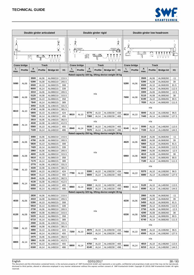
Double girder articulated Double girder rigid Double girder low headroom
Crane bridge Track Crane bridge Track Crane bridge Track
L max. Profile A
max. Profile Bridge kit H1 L max. Profile A
max. Profile Bridge kit H1 L max. Profile A
max. Profile Bridge kit H1
Rated capacity 63 kg, lifting device weight 30 kg
6210 AL06
4180 AL06 AL06B210 215.5
n/a
6410 AL06
4140 AL06 AL06B260 -11
6330 AL08 AL06B210 265.5 6280 AL08 AL06B260 39
7510 AL10 AL06B215 308 7450 AL10 AL06B265 81.5
8000 AL14 AL06B215 339 8000 AL14 AL06B265 112.5
8780 AL08
3850 AL06 AL08B210 265.5
8980 AL08
3810 AL06 AL08B260 -12.5
5880 AL08 AL08B210 315.5 5840 AL08 AL08B260 38
7040 AL10 AL08B215 358 6990 AL10 AL08B265 80.5
8000 AL14 AL08B215 389 8000 AL14 AL08B265 111.5
8880 AL10
3510 AL06 AL10B215 331.5 n/a
5410 AL08 AL10B215 381.5
6560 AL10 AL10B210 424 8880 AL10
6520 AL10 AL10B230 434 9080 AL10
6600 AL10 AL10B260 96.5
8000 AL14 AL10B210 455 8000 AL14 AL10B230 465 8000 AL14 AL10B260 127.5
9040 AL14
3300 AL06 AL14B215 362.5 n/a n/a
5110 AL08 AL14B215 412.5
6230 AL10 AL14B210 455 9040 AL14
6190 AL10 AL14B230 465 9240 AL14
6270 AL10 AL14B260 113.5
7880 AL14 AL14B210 486 7840 AL14 AL14B230 496 7920 AL14 AL14B260 144.5
Rated capacity 80 kg, lifting device weight 30 kg
5970 AL06
4030 AL06 AL06B210 215.5
n/a
6170 AL06
4000 AL06 AL06B260 -11
6140 AL08 AL06B210 265.5 6100 AL08 AL06B260 39
7300 AL10 AL06B215 308 7260 AL10 AL06B265 81.5
8000 AL14 AL06B215 339 8000 AL14 AL06B265 112.5
8520 AL08
3740 AL06 AL08B210 265.5
8720 AL08
3710 AL06 AL08B260 -12.5
5730 AL08 AL08B210 315.5 5690 AL08 AL08B260 38
6870 AL10 AL08B215 358 6830 AL10 AL08B265 80.5
8000 AL14 AL08B215 389 8000 AL14 AL08B265 111.5
8860 AL10
3410 AL06 AL10B215 331.5 n/a
5270 AL08 AL10B215 381.5
6410 AL10 AL10B210 424 8860 AL10
6370 AL10 AL10B230 434 9060 AL10
6440 AL10 AL10B260 96.5
8000 AL14 AL10B210 455 8000 AL14 AL10B230 465 8000 AL14 AL10B260 127.5
9020 AL14
3220 AL06 AL14B215 362.5 n/a n/a
4990 AL08 AL14B215 412.5
6100 AL10 AL14B210 455 9020 AL14
6060 AL10 AL14B230 465 9220 AL14
6130 AL10 AL14B260 113.5
7730 AL14 AL14B210 486 7690 AL14 AL14B230 496 7770 AL14 AL14B260 144.5
Rated capacity 125 kg, lifting device weight 30 kg
5420 AL06
3710 AL06 AL06B210 215.5
n/a
5620 AL06
3700 AL06 AL06B260 -11
5680 AL08 AL06B210 265.5 5670 AL08 AL06B260 39
6820 AL10 AL06B215 308 6810 AL10 AL06B265 81.5
8000 AL14 AL06B215 339 8000 AL14 AL06B265 112.5
7900 AL08
3480 AL06 AL08B210 265.5
8100 AL08
3460 AL06 AL08B260 -12.5
5360 AL08 AL08B210 315.5 5340 AL08 AL08B260 38
6470 AL10 AL08B215 358 6450 AL10 AL08B265 80.5
8000 AL14 AL08B215 389 8000 AL14 AL08B265 111.5
8800 AL10
3190 AL06 AL10B215 331.5 n/a
4950 AL08 AL10B215 381.5
6040 AL10 AL10B210 424 8800 AL10
6010 AL10 AL10B230 434 9000 AL10
6080 AL10 AL10B260 96.5
7660 AL14 AL10B210 455 7630 AL14 AL10B230 465 7710 AL14 AL10B260 127.5
8970 AL14
3030 AL06 AL14B215 362.5 n/a n/a
4710 AL08 AL14B215 412.5
5770 AL10 AL14B210 455 8970 AL14
5740 AL10 AL14B230 465 9170 AL14
5810 AL10 AL14B260 113.5
7360 AL14 AL14B210 486 7320 AL14 AL14B230 496 7400 AL14 AL14B260 144.5
TECHNICAL GUIDE
English 02/01/2017 38 / 93This document and the information contained herein, is the exclusive property of SWF Krantechnik GmbH and represents a non-public, confidential and proprietary trade secret that may not be reproduced,
disclosed to third parties, altered or otherwise employed in any manner whatsoever without the express written consent of SWF Krantechnik GmbH. Copyright © (2013) SWF Krantechnik GmbH. All rights
reserved.
Double girder articulated Double girder rigid Double girder low headroom
Crane bridge Track Crane bridge Track Crane bridge Track
L max. Profile A
max. Profile Bridge kit H1 L max. Profile A
max. Profile Bridge kit H1 L max. Profile A
max. Profile Bridge kit H1
Rated capacity 160 kg, lifting device weight 30 kg
5080 AL06
3500 AL06 AL06B210 215.5
n/a
5280 AL06
3500 AL06 AL06B260 -11
5390 AL08 AL06B210 265.5 5390 AL08 AL06B260 39
6500 AL10 AL06B215 308 6500 AL10 AL06B265 81.5
8000 AL14 AL06B215 339 8000 AL14 AL06B265 112.5
7490 AL08
3310 AL06 AL08B210 265.5
7690 AL08
3300 AL06 AL08B260 -12.5
5120 AL08 AL08B210 315.5 5110 AL08 AL08B260 38
6200 AL10 AL08B215 358 6190 AL10 AL08B265 80.5
7840 AL14 AL08B215 389 7830 AL14 AL08B265 111.5
8610 AL10
3050 AL06 AL10B215 331.5 n/a
4740 AL08 AL10B215 381.5
5800 AL10 AL10B210 424 8610 AL10
5770 AL10 AL10B230 434 8810 AL10
5840 AL10 AL10B260 96.5
7390 AL14 AL10B210 455 7360 AL14 AL10B230 465 7440 AL14 AL10B260 127.5
8940 AL14
2910 AL06 AL14B215 362.5 n/a n/a
4530 AL08 AL14B215 412.5
5560 AL10 AL14B210 455 8940 AL14
5530 AL10 AL14B230 465 9140 AL14
5590 AL10 AL14B260 113.5
7100 AL14 AL14B210 486 7070 AL14 AL14B230 496 7150 AL14 AL14B260 144.5
Rated capacity 250 kg, lifting device weight 30 kg
4420 AL06
3080 AL06 AL06B210 215.5
n/a
4620 AL06
3110 AL06 AL06B260 -11
4790 AL08 AL06B210 265.5 4820 AL08 AL06B260 39
5830 AL10 AL06B215 308 5860 AL10 AL06B265 81.5
7420 AL14 AL06B215 339 7460 AL14 AL06B265 112.5
6660 AL08
2960 AL06 AL08B210 265.5
6860 AL08
2960 AL06 AL08B260 -12.5
4600 AL08 AL08B210 315.5 4610 AL08 AL08B260 38
5610 AL10 AL08B215 358 5620 AL10 AL08B265 80.5
7170 AL14 AL08B215 389 7180 AL14 AL08B265 111.5
7790 AL10
2770 AL06 AL10B215 331.5 n/a
4330 AL08 AL10B215 381.5
5320 AL10 AL10B210 424 7790 AL10
5300 AL10 AL10B230 434 7990 AL10
5370 AL10 AL10B260 96.5
6830 AL14 AL10B210 455 6800 AL14 AL10B230 465 6880 AL14 AL10B260 127.5
8860 AL14
2640 AL06 AL14B215 362.5 n/a n/a
4130 AL08 AL14B215 412.5
5090 AL10 AL14B210 455 8860 AL14
5060 AL10 AL14B230 465 9060 AL14
5120 AL10 AL14B260 113.5
6550 AL14 AL14B210 486 6520 AL14 AL14B230 496 6590 AL14 AL14B260 144.5
Rated capacity 320 kg, lifting device weight 35 kg
4030 AL06
2830 AL06 AL06B210 215.5
n/a
4230 AL06
2860 AL06 AL06B260 -11
4410 AL08 AL06B210 265.5 4460 AL08 AL06B260 39
5390 AL10 AL06B215 308 5450 AL10 AL06B265 81.5
6910 AL14 AL06B215 339 6980 AL14 AL06B265 112.5
6130 AL08
2730 AL06 AL08B210 265.5
6330 AL08
2750 AL06 AL08B260 -12.5
4260 AL08 AL08B210 315.5 4290 AL08 AL08B260 38
5220 AL10 AL08B215 358 5250 AL10 AL08B265 80.5
6710 AL14 AL08B215 389 6740 AL14 AL08B265 111.5
7250 AL10
2590 AL06 AL10B215 331.5 n/a
4050 AL08 AL10B215 381.5
4990 AL10 AL10B210 424 7250 AL10
4970 AL10 AL10B230 434 7450 AL10
5040 AL10 AL10B260 96.5
6440 AL14 AL10B210 455 6410 AL14 AL10B230 465 6500 AL14 AL10B260 127.5
8800 AL14
2470 AL06 AL14B215 362.5 n/a n/a
3860 AL08 AL14B215 412.5
4770 AL10 AL14B210 455 8800 AL14
4750 AL10 AL14B230 465 9000 AL14
4810 AL10 AL14B260 113.5
6160 AL14 AL14B210 486 6140 AL14 AL14B230 496 6210 AL14 AL14B260 144.5
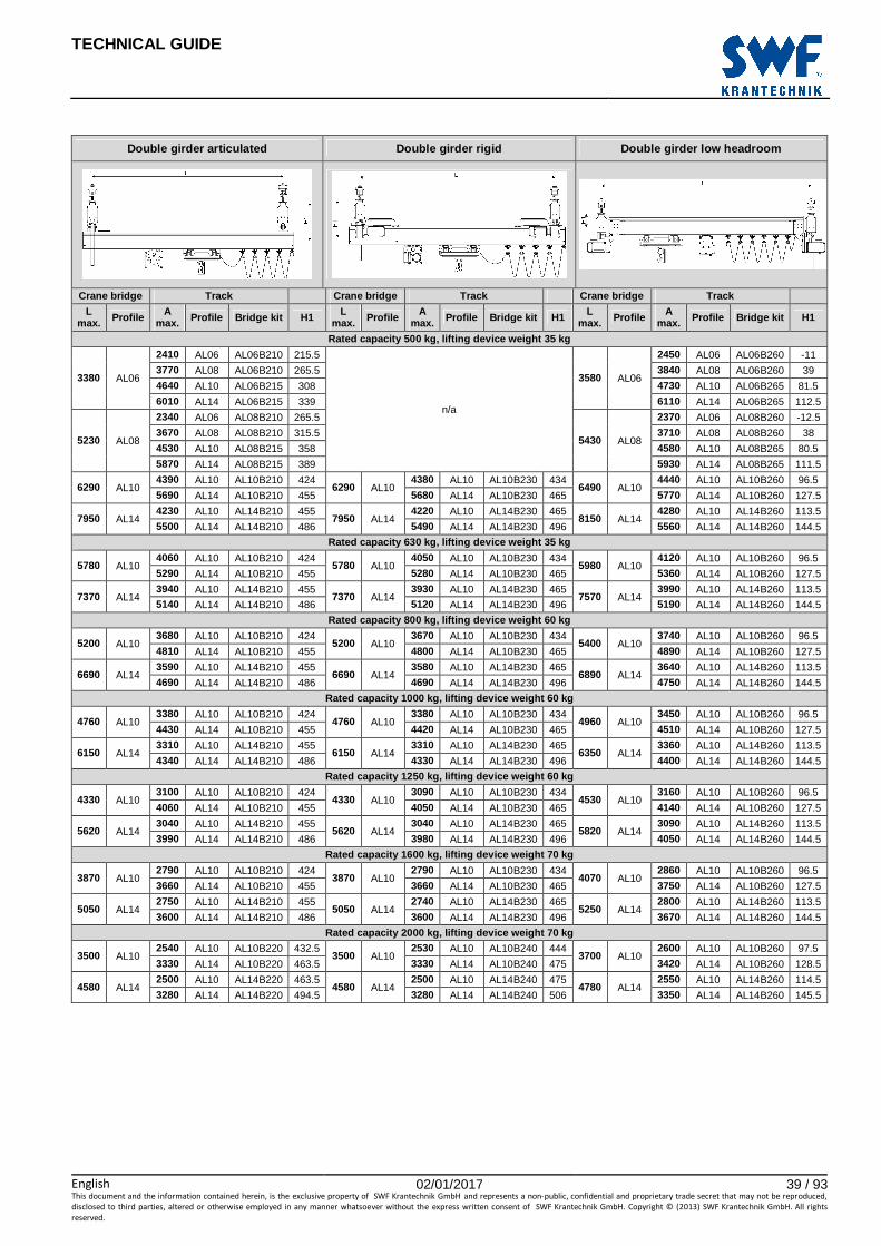
TECHNICAL GUIDE
English 02/01/2017 39 / 93This document and the information contained herein, is the exclusive property of SWF Krantechnik GmbH and represents a non-public, confidential and proprietary trade secret that may not be reproduced,
disclosed to third parties, altered or otherwise employed in any manner whatsoever without the express written consent of SWF Krantechnik GmbH. Copyright © (2013) SWF Krantechnik GmbH. All rights
reserved.
Double girder articulated Double girder rigid Double girder low headroom
Crane bridge Track Crane bridge Track Crane bridge Track
L max. Profile A
max. Profile Bridge kit H1 L max. Profile A
max. Profile Bridge kit H1 L max. Profile A
max. Profile Bridge kit H1
Rated capacity 500 kg, lifting device weight 35 kg
3380 AL06
2410 AL06 AL06B210 215.5
n/a
3580 AL06
2450 AL06 AL06B260 -11
3770 AL08 AL06B210 265.5 3840 AL08 AL06B260 39
4640 AL10 AL06B215 308 4730 AL10 AL06B265 81.5
6010 AL14 AL06B215 339 6110 AL14 AL06B265 112.5
5230 AL08
2340 AL06 AL08B210 265.5
5430 AL08
2370 AL06 AL08B260 -12.5
3670 AL08 AL08B210 315.5 3710 AL08 AL08B260 38
4530 AL10 AL08B215 358 4580 AL10 AL08B265 80.5
5870 AL14 AL08B215 389 5930 AL14 AL08B265 111.5
6290 AL10 4390 AL10 AL10B210 424
6290 AL10 4380 AL10 AL10B230 434
6490 AL10 4440 AL10 AL10B260 96.5
5690 AL14 AL10B210 455 5680 AL14 AL10B230 465 5770 AL14 AL10B260 127.5
7950 AL14 4230 AL10 AL14B210 455
7950 AL14 4220 AL10 AL14B230 465
8150 AL14 4280 AL10 AL14B260 113.5
5500 AL14 AL14B210 486 5490 AL14 AL14B230 496 5560 AL14 AL14B260 144.5
Rated capacity 630 kg, lifting device weight 35 kg
5780 AL10 4060 AL10 AL10B210 424
5780 AL10 4050 AL10 AL10B230 434
5980 AL10 4120 AL10 AL10B260 96.5
5290 AL14 AL10B210 455 5280 AL14 AL10B230 465 5360 AL14 AL10B260 127.5
7370 AL14 3940 AL10 AL14B210 455
7370 AL14 3930 AL10 AL14B230 465
7570 AL14 3990 AL10 AL14B260 113.5
5140 AL14 AL14B210 486 5120 AL14 AL14B230 496 5190 AL14 AL14B260 144.5
Rated capacity 800 kg, lifting device weight 60 kg
5200 AL10 3680 AL10 AL10B210 424
5200 AL10 3670 AL10 AL10B230 434
5400 AL10 3740 AL10 AL10B260 96.5
4810 AL14 AL10B210 455 4800 AL14 AL10B230 465 4890 AL14 AL10B260 127.5
6690 AL14 3590 AL10 AL14B210 455
6690 AL14 3580 AL10 AL14B230 465
6890 AL14 3640 AL10 AL14B260 113.5
4690 AL14 AL14B210 486 4690 AL14 AL14B230 496 4750 AL14 AL14B260 144.5
Rated capacity 1000 kg, lifting device weight 60 kg
4760 AL10 3380 AL10 AL10B210 424
4760 AL10 3380 AL10 AL10B230 434
4960 AL10 3450 AL10 AL10B260 96.5
4430 AL14 AL10B210 455 4420 AL14 AL10B230 465 4510 AL14 AL10B260 127.5
6150 AL14 3310 AL10 AL14B210 455
6150 AL14 3310 AL10 AL14B230 465
6350 AL14 3360 AL10 AL14B260 113.5
4340 AL14 AL14B210 486 4330 AL14 AL14B230 496 4400 AL14 AL14B260 144.5
Rated capacity 1250 kg, lifting device weight 60 kg
4330 AL10 3100 AL10 AL10B210 424
4330 AL10 3090 AL10 AL10B230 434
4530 AL10 3160 AL10 AL10B260 96.5
4060 AL14 AL10B210 455 4050 AL14 AL10B230 465 4140 AL14 AL10B260 127.5
5620 AL14 3040 AL10 AL14B210 455
5620 AL14 3040 AL10 AL14B230 465
5820 AL14 3090 AL10 AL14B260 113.5
3990 AL14 AL14B210 486 3980 AL14 AL14B230 496 4050 AL14 AL14B260 144.5
Rated capacity 1600 kg, lifting device weight 70 kg
3870 AL10 2790 AL10 AL10B210 424
3870 AL10 2790 AL10 AL10B230 434
4070 AL10 2860 AL10 AL10B260 96.5
3660 AL14 AL10B210 455 3660 AL14 AL10B230 465 3750 AL14 AL10B260 127.5
5050 AL14 2750 AL10 AL14B210 455
5050 AL14 2740 AL10 AL14B230 465
5250 AL14 2800 AL10 AL14B260 113.5
3600 AL14 AL14B210 486 3600 AL14 AL14B230 496 3670 AL14 AL14B260 144.5
Rated capacity 2000 kg, lifting device weight 70 kg
3500 AL10 2540 AL10 AL10B220 432.5
3500 AL10 2530 AL10 AL10B240 444
3700 AL10 2600 AL10 AL10B260 97.5
3330 AL14 AL10B220 463.5 3330 AL14 AL10B240 475 3420 AL14 AL10B260 128.5
4580 AL14 2500 AL10 AL14B220 463.5
4580 AL14 2500 AL10 AL14B240 475
4780 AL14 2550 AL10 AL14B260 114.5
3280 AL14 AL14B220 494.5 3280 AL14 AL14B240 506 3350 AL14 AL14B260 145.5

TECHNICAL GUIDE
English 02/01/2017 40 / 93This document and the information contained herein, is the exclusive property of SWF Krantechnik GmbH and represents a non-public, confidential and proprietary trade secret that may not be reproduced,
disclosed to third parties, altered or otherwise employed in any manner whatsoever without the express written consent of SWF Krantechnik GmbH. Copyright © (2013) SWF Krantechnik GmbH. All rights
reserved.
Monorail
The following abbreviations are used in the quick selection table:
Amax Maximum distance between suspensions on the track
Bmax Maximum distance between suspension and connection between track/monorail segments
D1 Outreach of track/monorail, opposite of festoon side
D2 Outreach of track/monorail, festoon side
H1 Height of the monorail (between top of monorail profile and top of push trolley bolt)

TECHNICAL GUIDE
English 02/01/2017 41 / 93This document and the information contained herein, is the exclusive property of SWF Krantechnik GmbH and represents a non-public, confidential and proprietary trade secret that may not be reproduced,
disclosed to third parties, altered or otherwise employed in any manner whatsoever without the express written consent of SWF Krantechnik GmbH. Copyright © (2013) SWF Krantechnik GmbH. All rights
reserved.
Monorail
Amax Profile Bmax D1, D2 min. D1, D2 max. Push trolley H1
Rated capacity 63 kg, lifting device weight 30 kg
5390 AL06 530 100 150 AL08T100 172.5
7870 AL08 780 100 150 AL08T100 222
8000 AL10 910 100 150 AL14T100 265
8000 AL14 1080 100 150 AL14T100 296
Rated capacity 80 kg, lifting device weight 30 kg
5060 AL06 500 100 150 AL08T100 172.5
7480 AL08 740 100 150 AL08T100 222
8000 AL10 870 100 150 AL14T100 265
8000 AL14 1050 100 150 AL14T100 296
Rated capacity 125 kg, lifting device weight 30 kg
4410 AL06 440 100 150 AL08T100 172.5
6650 AL08 660 100 150 AL08T100 222
7920 AL10 790 100 150 AL14T100 265
8000 AL14 960 100 150 AL14T100 296
Rated capacity 160 kg, lifting device weight 30 kg
4040 AL06 400 100 150 AL08T100 172.5
6150 AL08 610 100 150 AL08T100 222
7400 AL10 730 100 150 AL14T100 265
8000 AL14 910 100 150 AL14T100 296
Rated capacity 250 kg, lifting device weight 30 kg
3390 AL06 330 100 150 AL08T100 172.5
5240 AL08 520 100 150 AL08T100 222
6380 AL10 630 100 150 AL14T100 265
8000 AL14 800 100 150 AL14T100 296
Rated capacity 320 kg, lifting device weight 35 kg
3040 AL06 300 100 150 AL08T100 172.5
4720 AL08 470 100 150 AL08T100 222
5790 AL10 570 100 150 AL14T100 265
7370 AL14 730 100 150 AL14T100 296
Rated capacity 500 kg, lifting device weight 35 kg
2500 AL06 240 100 150 AL08T100 172.5
3910 AL08 390 100 150 AL08T100 222
4830 AL10 480 100 150 AL14T100 265
6240 AL14 620 100 150 AL14T100 296
Rated capacity 630 kg, lifting device weight 35 kg
4370 AL10 430 100 150 AL14T100 265
5670 AL14 560 100 150 AL14T100 296
Rated capacity 800 kg, lifting device weight 60 kg
3870 AL10 380 100 150 AL14T100 265
5040 AL14 500 100 150 AL14T100 296
Rated capacity 1000 kg, lifting device weight 60 kg
3500 AL10 340 100 150 AL14T100 265
4580 AL14 450 100 150 AL14T100 296
Rated capacity 1250 kg, lifting device weight 60 kg
3150 AL10 310 100 150 AL14T200 270
4130 AL14 410 100 150 AL14T200 301
Rated capacity 1600 kg, lifting device weight 70 kg
2800 AL10 270 100 150 AL14T200 270
3670 AL14 360 100 150 AL14T200 301
Rated capacity 2000 kg, lifting device weight 70 kg
2520 AL10 250 100 150 AL14T200 270
3310 AL14 330 100 150 AL14T200 301

TECHNICAL GUIDE
English 02/01/2017 42 / 93This document and the information contained herein, is the exclusive property of SWF Krantechnik GmbH and represents a non-public, confidential and proprietary trade secret that may not be reproduced,
disclosed to third parties, altered or otherwise employed in any manner whatsoever without the express written consent of SWF Krantechnik GmbH. Copyright © (2013) SWF Krantechnik GmbH. All rights
reserved.
4.3 Detailed calculation
4.3.1 Data required for calculation
To properly select a crane system, knowledge of the crane operation environment, the limits of the components, the geometry of the crane, the type of load (including dynamic factor), and product weights are required.
To determine the suitable product and profiles, product weights need to be calculated. The calculations are explained in the following sections, and summarized in the table below.
Product Description Suitability Weight [kg/m]
AL06 Profile Crane bridge and track 6.5
AL08 Profile Crane bridge and track 8.6
AL10 Profile Crane bridge and track 10.9
AL14 Profile Crane bridge and track 14.6
Product Description [Kg] (max.) Suitability Weight [kg]
AL08T100 Push trolley, single 500, max. AL06 and AL08 profiles, single girder crane bridges and monorails 2.3
AL14T100 Push trolley, single 1250, max. AL10 and AL14 profiles, single girder crane bridges and monorails 3.2
AL14T200 Push trolley, double 2500, max. AL10 and AL14 profiles, single girder crane bridges and monorails 12.2
AL08T500 Push trolley 500 AL06 and AL08 profiles, double girder crane bridges 33.0
AL14T500 Push trolley 2000 AL10 and AL14 profiles, double girder crane bridges 52.7
ALTM2 Motor trolley AL10 and AL14 profiles 24.0
Lifting devices Refer to the lifting device technical documentation
Bridge kit See chapter Crane dimensions
Note : The results of the detailed calculation must be evaluated with the sales configurator.
4.3.2 Calculating load spectrum and determining rat ed capacity
All tables are given for a load spectrum kp=1, spectrum class Q4, and utilization class U2 (maximum number of hoisting cycles = 63000 at full capacity).
When a higher number of cycles is required, the rated capacity shall be increased compared to the real load to decrease the load spectrum and thereby stay in the A4 application class.
The load spectrum is calculated as follows:
Abbreviations ml Real lifted loads
n Number of hoisting cycles when the hoisted load is equal to ml nmax Number of hoisting cycles determining the total duration of use
RC Rated capacity

TECHNICAL GUIDE
English 02/01/2017 43 / 93This document and the information contained herein, is the exclusive property of SWF Krantechnik GmbH and represents a non-public, confidential and proprietary trade secret that may not be reproduced,
disclosed to third parties, altered or otherwise employed in any manner whatsoever without the express written consent of SWF Krantechnik GmbH. Copyright © (2013) SWF Krantechnik GmbH. All rights
reserved.
4.3.3 Determining rail type
The following graphs show the maximal crane spans and loadings. The loading is not the rated capacity. The weight of the lifting device, motor trolley, and possible additional weight, such as power feeding lines and handling equipment, have to be added to the lifted load.
These curves can be used for crane bridge span and maximum distance between track suspensions for crane systems with one single crane bridge. In this case, crane bridge dead weight shall be added.
Other limits that can reduce the maximum span: outreach, length of segment (connections are not allowed on single girder crane bridges), loading of suspensions, among others.
Note : In addition to this maximum span, the following points must be checked:
• Maximum outreach
• Trolley and suspension capacities
• Connection positions on the track.
Abbreviations used in the calculations
Abbreviation Description RC Rated capacity
HW Lifting device weight
TW Push trolley weight
MW Motor trolley weight
PLW Profile linear weight
PL Bridge profile length (including outreaches)
GN Girder number
HF Horizontal force
BW Bridge kit weight
PTL Push trolley loading
CBL Crane bridge loading
TL Track loading
SL Suspension loading
A Distance between suspensions
MM Moving mass
Dynfactor Dynamic factor given by acceleration during lifting motion (Dynfactor = 0.25)

TECHNICAL GUIDE
English 02/01/2017 44 / 93This document and the information contained herein, is the exclusive property of SWF Krantechnik GmbH and represents a non-public, confidential and proprietary trade secret that may not be reproduced,
disclosed to third parties, altered or otherwise employed in any manner whatsoever without the express written consent of SWF Krantechnik GmbH. Copyright © (2013) SWF Krantechnik GmbH. All rights
reserved.
Push trolley selection
The trolley for the lifting device shall be selected according to the loading limit
Trolley loading is limited as follows:
Trolley AL08T100 AL08T500 AL14T100 AL14T200 AL14T500
Use case AL06/AL08 single girder
AL06/AL08 double girder
AL10/AL14 single trolley single girder
AL10/AL14 double trolley single girder
AL10/AL14 double girder
Loading limit [kg] 600 600 1250 2500 2500
For more information on trolleys, see chapter Trolleys.
Single girder crane bridges, deflection criteria L/ 500
Loading calculation:

TECHNICAL GUIDE
English 02/01/2017 45 / 93This document and the information contained herein, is the exclusive property of SWF Krantechnik GmbH and represents a non-public, confidential and proprietary trade secret that may not be reproduced,
disclosed to third parties, altered or otherwise employed in any manner whatsoever without the express written consent of SWF Krantechnik GmbH. Copyright © (2013) SWF Krantechnik GmbH. All rights
reserved.
Double girder crane bridges, deflection criteria L/ 500
Loading calculation:
Tracks and monorails, deflection criteria L/500

TECHNICAL GUIDE
English 02/01/2017 46 / 93This document and the information contained herein, is the exclusive property of SWF Krantechnik GmbH and represents a non-public, confidential and proprietary trade secret that may not be reproduced,
disclosed to third parties, altered or otherwise employed in any manner whatsoever without the express written consent of SWF Krantechnik GmbH. Copyright © (2013) SWF Krantechnik GmbH. All rights
reserved.
Loading calculations:
Track:
Check that the track loading is lower than the crane bridge trolley limit. The crane bridge trolley type is given in the bridge kit reference tables in chapter Crane dimensions.
Track rail size AL06/AL08 AL10/AL14 AL10/AL14
Bridge trolley type Single push trolley Single push trolley Double push trolley
Loading limit [kg] 600 1250 2500
Monorail:
4.3.4 Suspension limits and forces back to supporti ng structure
The suspension loading is calculated as follows:
The suspension loading is limited to 3000 kg.
The vertical force back to the supporting structure to be taken into account for checking is calculated without the dynamic factor.
The horizontal force back to the supporting structure to be taken into account for checking is 10% of the moving mass.

TECHNICAL GUIDE
English 02/01/2017 47 / 93This document and the information contained herein, is the exclusive property of SWF Krantechnik GmbH and represents a non-public, confidential and proprietary trade secret that may not be reproduced,
disclosed to third parties, altered or otherwise employed in any manner whatsoever without the express written consent of SWF Krantechnik GmbH. Copyright © (2013) SWF Krantechnik GmbH. All rights
reserved.
4.3.5 Examples of calculations
Load spectrum calculation
A crane is used to load a machine. The rated capacity of the crane is 500 kg. The lifting equipment is fitted with a lifting beam which weighs 120 kg. Each part weighs 300 kg, and is lifted from the floor and lowered onto the machine. After removing the part, the lifting beam is lifted and lowered to get the next part.
There are two hoisting cycles per production cycle (one with the load and one with the lifting beam only)
Spectrum factor calculation:
The spectrum class is Q3 (see table Load spectrum classes in chapter Technical regulations).
The maximum number of hoisting cycles in utilization group A4 is 125000 as per utilization class U3.
Example 1: Monorail
� Lifting capacity required: RC=500 kg � Lifting device weight: HW=50 kg � Manual movement
Trolley selection:
� PTL=500+50=550 kg � Push trolleys allowed: AL08T100, AL14T100 � AL14T200 will not bring added value � AL08T500 and AL14T500 are for double girder bridges only, not suitable for monorail
Rail type selection:
Push trolley RC [kg] HW [kg] TW MT TL
AL08T100 500 50 2.3 0 552.3
AL14T100 500 50 3.2 0 553.2

TECHNICAL GUIDE
English 02/01/2017 48 / 93This document and the information contained herein, is the exclusive property of SWF Krantechnik GmbH and represents a non-public, confidential and proprietary trade secret that may not be reproduced,
disclosed to third parties, altered or otherwise employed in any manner whatsoever without the express written consent of SWF Krantechnik GmbH. Copyright © (2013) SWF Krantechnik GmbH. All rights
reserved.
Maximum distance between suspensions:
� AL06: 2400 mm � AL08: 3800 mm � AL10: 4700 mm � AL14: 6100 mm
Suspension loading and vertical force to structure
Track rail size TL PLW [kg/m] A RC [kg] SL VF
AL06 552.3 6.5 2.4 500 692.9 567.9
AL08 552.3 8.6 3.8 500 689.7 564.7 AL10 553.2 10.9 4.7 500 729.5 604.5 AL14 553.2 14.6 6.1 500 767.3 642.3

TECHNICAL GUIDE
English 02/01/2017 49 / 93This document and the information contained herein, is the exclusive property of SWF Krantechnik GmbH and represents a non-public, confidential and proprietary trade secret that may not be reproduced,
disclosed to third parties, altered or otherwise employed in any manner whatsoever without the express written consent of SWF Krantechnik GmbH. Copyright © (2013) SWF Krantechnik GmbH. All rights
reserved.
Example 2: Light Crane System
� Lifting capacity required: RC=500 kg � Lifting device weight: HW=50 kg � Motor movement for cross travel direction, manual movement for long travel direction � Span L required: 5.6 m, outreach 100 mm
According to the requirements, an articulated crane bridge can be used in this example. To evaluate the most suitable crane bridge type, this example shows calculations with different alternatives.
Trolley selection:
� PTL=500+50=550 kg � Push trolleys allowed: AL08T100, AL14T100 (single girder bridges), AL08T500, AL14T500 (double girder
bridges) � Push trolley AL14T200 is not required because PTL is lower than 1250 kg
Rail type selection:
First calculate the crane bridge loading:
Push trolley RC [kg] HW [kg] TW MT CBL AL08T100 500 50 2.3 24 576.3
AL08T500 500 50 33 24 607
AL14T100 500 50 3.2 24 577.2
AL14T500 500 50 61.4 24 635.4
Maximum span allowed
Use the CBL values in the single or double girder graphs to check the maximum span L.

TECHNICAL GUIDE
English 02/01/2017 50 / 93This document and the information contained herein, is the exclusive property of SWF Krantechnik GmbH and represents a non-public, confidential and proprietary trade secret that may not be reproduced,
disclosed to third parties, altered or otherwise employed in any manner whatsoever without the express written consent of SWF Krantechnik GmbH. Copyright © (2013) SWF Krantechnik GmbH. All rights
reserved.
Single girder
Double girder
Profile and crane bridge type suitable with the required span:
Profile size Crane bridge type Bridge kit reference AL14 Single girder articulated AL14B110
AL10 Double girder articulated AL10B210
AL14 Double girder articulated AL14B210
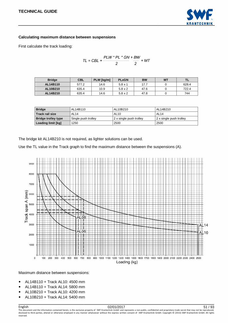
TECHNICAL GUIDE
English 02/01/2017 51 / 93This document and the information contained herein, is the exclusive property of SWF Krantechnik GmbH and represents a non-public, confidential and proprietary trade secret that may not be reproduced,
disclosed to third parties, altered or otherwise employed in any manner whatsoever without the express written consent of SWF Krantechnik GmbH. Copyright © (2013) SWF Krantechnik GmbH. All rights
reserved.
Calculating maximum distance between suspensions
First calculate the track loading:
Bridge CBL PLW [kg/m] PLxGN BW MT TL
AL14B110 577.2 14.6 5.8 x 1 17.7 0 628.4
AL10B210 635.4 10.9 5.8 x 2 47.6 0 722.4
AL14B210 635.4 14.6 5.8 x 2 47.8 0 744
Bridge AL14B110 AL10B210 AL14B210
Track rail size AL14 AL10 AL14
Bridge trolley type Single push trolley 2 x single push trolley 2 x single push trolley
Loading limit [kg] 1250 2500 2500
The bridge kit AL14B210 is not required, as lighter solutions can be used.
Use the TL value in the Track graph to find the maximum distance between the suspensions (A).
Maximum distance between suspensions:
� AL14B110 + Track AL10: 4500 mm � AL14B110 + Track AL14: 5800 mm � AL10B210 + Track AL10: 4200 mm � AL10B210 + Track AL14: 5400 mm

TECHNICAL GUIDE
English 02/01/2017 52 / 93This document and the information contained herein, is the exclusive property of SWF Krantechnik GmbH and represents a non-public, confidential and proprietary trade secret that may not be reproduced,
disclosed to third parties, altered or otherwise employed in any manner whatsoever without the express written consent of SWF Krantechnik GmbH. Copyright © (2013) SWF Krantechnik GmbH. All rights
reserved.
Suspension loading:
Crane system TL PLW [kg/m] A RC SL VF AL14B110 + Track AL10 628.4 10.9 4.5 500 802.4 677.4
AL14B110 + Track AL14 628.4 14.6 5.8 500 838.1 713.1
AL10B210 + Track AL10 722.4 10.9 4.2 500 893.2 768.2
AL10B210 + Track AL14 722.4 14.6 5.4 500 926.3 801.3
Moving mass:
Crane system CBL PLW [kg/m] PLxGN BW MT MM AL14B110 577.2 14.6 5.8 x 1 17.7 0 679.6
AL10B210 635.4 10.9 5.8 x 21) 47.6 0 809.5
1)Profile length is to be multiplied by 2 for double girder bridges.

TECHNICAL GUIDE
English 02/01/2017 53 / 93This document and the information contained herein, is the exclusive property of SWF Krantechnik GmbH and represents a non-public, confidential and proprietary trade secret that may not be reproduced,
disclosed to third parties, altered or otherwise employed in any manner whatsoever without the express written consent of SWF Krantechnik GmbH. Copyright © (2013) SWF Krantechnik GmbH. All rights
reserved.
4.4 Crane dimensions
List of measurements and dimensions used in the crane diagrams and specification tables:
L1 Length of monorail or track
L2 Length of crane bridge
D1 Outreach of track/monorail, without festoon
D2 Outreach of track/monorail, with festoon
D3 Outreach of crane bridge, without festoon
D4 Outreach of crane bridge, with festoon
E1 Distance between end of track/monorail and push trolley bolt axle (hook approach), without festoon
E2 Distance between end of track/monorail and push trolley bolt axle (hook approach), with festoon
E3 Distance between end of crane bridge and push trolley bolt axle (hook approach), without festoon
E4 Distance between end of crane bridge and push trolley bolt axle (hook approach), with festoon
A Distance between suspensions on the track
AMAX Maximum distance between suspensions, depends on total loading and profile size, has to be calculated according to instructions given in chapter Detailed calculation
B Maximum distance between suspension and connection between track/monorail segments
L Distance between tracks, maximum value to be calculated according to instructions given in chapter Detailed calculation depending on total load and profile size
HT Height of track (between top of track profile and top of crane bridge profile)
HB Height of crane bridge / monorail (between top of crane bridge / monorail profile and top of push trolley bolt)
HS Height of suspension, see chapter Selection of crane type
HC Height of lower part of the crane bridge kit (console)
HL Height of lower part of the push trolley
HU Distance between the highest point of hoist trolley and top of the crane bridge profile, or the height of triangle part in rigid crane
HM Height of motor trolley below profile (272.5 mm)
HF Height of festoon below profile (800 mm)
S Hook stroke
STR Travel along track
SBR Travel along crane bridge
TMU Length of motor trolley, based on the ALTM2 motor trolley, to be added to E1 or E2 depending on which side of push trolley the ALTM2 will be fitted
PFLTR Length of festoon on track for power feeding
PFLBR Length of festoon on crane bridge for power feeding
NFTTR Number of festoon trolleys on track
NFTBR Number of festoon trolleys on crane bridge

TECHNICAL GUIDE
English 02/01/2017 54 / 93This document and the information contained herein, is the exclusive property of SWF Krantechnik GmbH and represents a non-public, confidential and proprietary trade secret that may not be reproduced,
disclosed to third parties, altered or otherwise employed in any manner whatsoever without the express written consent of SWF Krantechnik GmbH. Copyright © (2013) SWF Krantechnik GmbH. All rights
reserved.
4.4.1 Monorail
Track E1 [mm] E2 [mm] HB [mm] D1, D2
min./max. [mm]
B [mm] Single push
trolley Double
push trolley TMU Single push
trolley Double
push trolley PFL Single push
trolley Double
push trolley AL06 140
n/a n/a 140+PFL
n/a 60+110xNFT 172.5
n/a
100/150 * AL08 140 140+PFL 222
AL10 150 300 370 150+PFL 300+PFL 60+110xNFT
265 270
AL14 150 300 370 150+PFL 300+PFL 296 301
*Note: B min. = 100 mm, B max. = 10 % of AMAX.
See chapter Festoon under profile for the calculation of the number of festoon trolleys (NFT) required.

TECHNICAL GUIDE
English 02/01/2017 55 / 93This document and the information contained herein, is the exclusive property of SWF Krantechnik GmbH and represents a non-public, confidential and proprietary trade secret that may not be reproduced,
disclosed to third parties, altered or otherwise employed in any manner whatsoever without the express written consent of SWF Krantechnik GmbH. Copyright © (2013) SWF Krantechnik GmbH. All rights
reserved.
4.4.2 Single girder articulated crane bridge
Track E1 [mm] E2 [mm] HT [mm] D1, D2
min./ max. [mm]
B [mm] Single push
trolley Double
push trolley TMU Single push trolley
Double push trolley PFLTR Single push
trolley Double
push trolley
AL06 140 n/a
n/a
140+PFL n/a
60+110xNFTTR
233 n/a
100/150 * AL08 140 140+PFL 283
AL10 150 300 150+PFL 300+PFL 325.5 334
AL14 150 300 150+PFL 300+PFL 356.5 365
*Note: B min.= 100 mm, B max. = 10 % of AMAX.

TECHNICAL GUIDE
English 02/01/2017 56 / 93This document and the information contained herein, is the exclusive property of SWF Krantechnik GmbH and represents a non-public, confidential and proprietary trade secret that may not be reproduced,
disclosed to third parties, altered or otherwise employed in any manner whatsoever without the express written consent of SWF Krantechnik GmbH. Copyright © (2013) SWF Krantechnik GmbH. All rights
reserved.
Crane bridge E3 [mm] E4 [mm] HB [mm] D3 min./
max. [mm]
D4 min./max. [mm] 1) Single push
trolley Double
push trolley TMU Single push trolley
Double push trolley PFLBR Single push
trolley Double
push trolley
AL06 140 n/a n/a
140+PFL n/a
60+110xNFTBR
172.5 n/a
100/150 100/150+PFLBR AL08 140 140+PFL 222
AL10 150 300 370 150+PFL 300+PFL 265 270 AL14 150 300 370 150+PFL 300+PFL 296 301
1)It is possible to extend the bridge outreach as much as is needed for storing the festoon (PFL). The extended area cannot be used for handling loads.
See chapter Festoon under profile for the calculation of the number of festoon trolleys (NFT) required.
The L2 is limited to the maximum profile length of 8 m, as no connections are allowed on the single girder crane bridges.
Bridge kit references and weights
Track profile Push trolley type Crane bridge profile and weight [kg]
AL06 AL08 AL10 AL14 AL06/08 Single push trolley AL06B11
0 9.6 AL08B11
0 9.9 AL10B115
) 10.9 AL14B115 11.7
AL10/14 Single push trolley AL06B115
16.2 AL08B115
16.5 AL10B110 17.4 AL14B110 17.7 AL10/14 Double push trolley n/a n/a AL10B120 40.4 AL14B120 40.7

TECHNICAL GUIDE
English 02/01/2017 57 / 93This document and the information contained herein, is the exclusive property of SWF Krantechnik GmbH and represents a non-public, confidential and proprietary trade secret that may not be reproduced,
disclosed to third parties, altered or otherwise employed in any manner whatsoever without the express written consent of SWF Krantechnik GmbH. Copyright © (2013) SWF Krantechnik GmbH. All rights
reserved.
4.4.3 Single girder rigid crane bridge
Track E1 [mm] E2 [mm] HT [mm] D1, D2
min./max. [mm]
B [mm] Single push
trolley Double push
trolley TMU Single push trolley
Double push trolley PFLRW Single push
trolley Double push
trolley
AL10 810 810 n/a 150+PFL 300+PFL 60+110xNFTTR 335.5 345.6 100/150 *
AL14 810 810 n/a 150+PFL 300+PFL 366.5 376.6
*Note: B min. = 100 mm, B max. = 10 % of AMAX.
The ALTM motor trolley fits inside the triangle part, so no additional length is required.
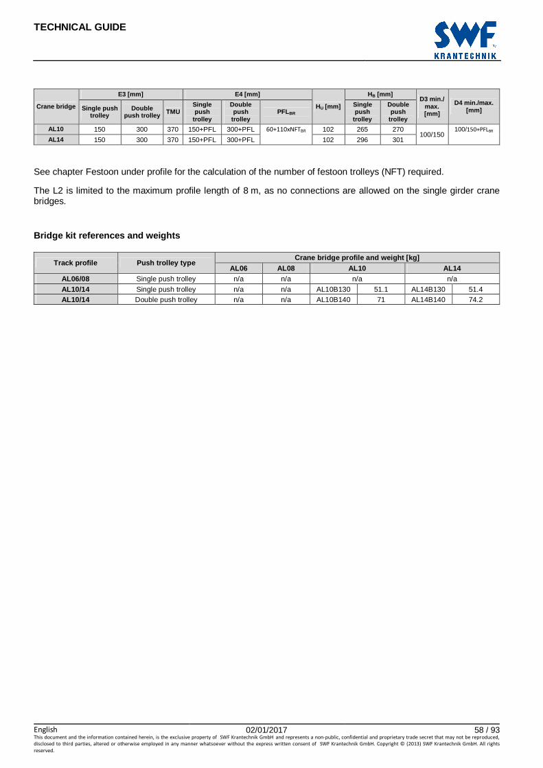
TECHNICAL GUIDE
English 02/01/2017 58 / 93This document and the information contained herein, is the exclusive property of SWF Krantechnik GmbH and represents a non-public, confidential and proprietary trade secret that may not be reproduced,
disclosed to third parties, altered or otherwise employed in any manner whatsoever without the express written consent of SWF Krantechnik GmbH. Copyright © (2013) SWF Krantechnik GmbH. All rights
reserved.
Crane bridge
E3 [mm] E4 [mm]
HU [mm]
HB [mm] D3 min./
max. [mm]
D4 min./max. [mm] Single push
trolley Double
push trolley TMU Single push
trolley
Double push
trolley PFLBR
Single push
trolley
Double push
trolley
AL10 150 300 370 150+PFL 300+PFL 60+110xNFTBR 102 265 270 100/150
100/150+PFLBR
AL14 150 300 370 150+PFL 300+PFL 102 296 301
See chapter Festoon under profile for the calculation of the number of festoon trolleys (NFT) required.
The L2 is limited to the maximum profile length of 8 m, as no connections are allowed on the single girder crane bridges.
Bridge kit references and weights
Track profile Push trolley type Crane bridge profile and weight [kg]
AL06 AL08 AL10 AL14 AL06/08 Single push trolley n/a n/a n/a n/a
AL10/14 Single push trolley n/a n/a AL10B130 51.1 AL14B130 51.4 AL10/14 Double push trolley n/a n/a AL10B140 71 AL14B140 74.2
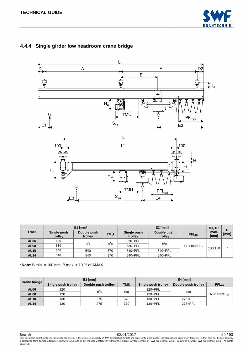
TECHNICAL GUIDE
English 02/01/2017 59 / 93This document and the information contained herein, is the exclusive property of SWF Krantechnik GmbH and represents a non-public, confidential and proprietary trade secret that may not be reproduced,
disclosed to third parties, altered or otherwise employed in any manner whatsoever without the express written consent of SWF Krantechnik GmbH. Copyright © (2013) SWF Krantechnik GmbH. All rights
reserved.
4.4.4 Single girder low headroom crane bridge
Track E1 [mm] E2 [mm] D1, D2
max. [mm]
B [mm] Single push
trolley Double push
trolley TMU Single push trolley
Double push trolley PFLTR
AL06 530 n/a n/a
530+PFL n/a
60+110xNFTTR 100/150 *
AL08 530 530+PFL
AL10 540 540 370 540+PFL 540+PFL AL14 540 540 370 540+PFL 540+PFL
*Note: B min. = 100 mm, B max. = 10 % of AMAX.
Crane bridge E3 [mm] E4 [mm]
Single push trolley Double push trolley TMU Single push trolley Double push trolley PFLBR AL06 120
n/a n/a 120+PFL
n/a 60+110xNFTBR AL08 120 120+PFL
AL10 130 275 370 130+PFL 275+PFL AL14 130 275 370 130+PFL 275+PFL

TECHNICAL GUIDE
English 02/01/2017 60 / 93This document and the information contained herein, is the exclusive property of SWF Krantechnik GmbH and represents a non-public, confidential and proprietary trade secret that may not be reproduced,
disclosed to third parties, altered or otherwise employed in any manner whatsoever without the express written consent of SWF Krantechnik GmbH. Copyright © (2013) SWF Krantechnik GmbH. All rights
reserved.
See chapter Festoon under profile for the calculation of the number of festoon trolleys (NFT) required.
The L2 is limited to the maximum profile length of 8 m, as no connections are allowed on the single girder crane bridges.
Crane bridge HT [mm] HB [mm]
HL [mm] AL06 AL08 AL10 AL14 Single push trolley Double push trolley
AL06 2 52 94.5 125.5 172.5 n/a
333
AL08 -42.5 7.5 50 81 222.5 377.5 AL10 n/a n/a 5.5 36.5 265 270 422 AL14 n/a n/a -24.5 6.5 296 301 452
Note : A negative HT value means that the crane bridge is higher than the track.
Bridge kit references and weights
Track profile Push trolley type Crane bridge profile and weight [kg]
AL06 AL08 AL10 AL14 AL06/08 Single push trolley AL06B160 34.7 AL08B160 44.8 n/a n/a
AL10/14 Single push trolley AL06B165 41.3 AL08B165 51.4 AL10B160 58.7 AL14B160 59.7

TECHNICAL GUIDE
English 02/01/2017 61 / 93This document and the information contained herein, is the exclusive property of SWF Krantechnik GmbH and represents a non-public, confidential and proprietary trade secret that may not be reproduced,
disclosed to third parties, altered or otherwise employed in any manner whatsoever without the express written consent of SWF Krantechnik GmbH. Copyright © (2013) SWF Krantechnik GmbH. All rights
reserved.
4.4.5 Double girder articulated crane bridge
Track
E1 [mm] E2 [mm] HT [mm] D1, D2
min./max. [mm]
B [mm]
Single push
trolley
Double push
trolley TMU
Single push
trolley
Double push
trolley PFLTR Single push
trolley Double
push trolley
AL06 440 n/a n/a
440+PFL n/a
60+110xNFTTR
233 n/a
100/150 * AL08 440 440+PFL 283
AL10 500 650 370 500+PFL 650+PFL 325.5 333.9
AL14 500 650 370 500+PFL 650+PFL 356.5 364.9
*Note: B min. = 100 mm, B max. = 10 % of AMAX.

TECHNICAL GUIDE
English 02/01/2017 62 / 93This document and the information contained herein, is the exclusive property of SWF Krantechnik GmbH and represents a non-public, confidential and proprietary trade secret that may not be reproduced,
disclosed to third parties, altered or otherwise employed in any manner whatsoever without the express written consent of SWF Krantechnik GmbH. Copyright © (2013) SWF Krantechnik GmbH. All rights
reserved.
Crane bridge E3 [mm] E4 [mm]
HU HL HB [mm] D3
min./max. [mm]
D4 min./max. [mm] Double push
trolley TMU Double push trolley PFLBR Double push
trolley AL06 318
n/a 258+PFL
60+110xNFTBR
-42.5 238.5 -17.5
100/150 100/150+PFLBR AL08 318 258+PFL 7.5 288.5 32.5 AL10 378 370 323+PFL 54 330 98.5
AL14 378 370 323+PFL 85 361 129.5
The B max. dimension also applies between the crane bridge suspension and the connection set fitted on the crane bridge.
See chapter Festoon under profile for the calculation of the number of festoon trolleys (NFT) required.
Bridge kit references and weights
Track profile Push trolley type Crane bridge profile and weight [kg]
AL06 AL08 AL10 AL14 AL06/08 Single push trolley AL06B210 27.8 AL08B210 29.5 AL10B215 34.2 AL14B215 35.7
AL10/14 Single push trolley AL06B215 40.6 AL08B215 42.6 AL10B210 47.6 AL14B210 47.8
AL10/14 Double push trolley n/a n/a AL10B220 74.2 AL14B220 75.8
Note : The connection sets on girders must be installed diagonally.

TECHNICAL GUIDE
English 02/01/2017 63 / 93This document and the information contained herein, is the exclusive property of SWF Krantechnik GmbH and represents a non-public, confidential and proprietary trade secret that may not be reproduced,
disclosed to third parties, altered or otherwise employed in any manner whatsoever without the express written consent of SWF Krantechnik GmbH. Copyright © (2013) SWF Krantechnik GmbH. All rights
reserved.
4.4.6 Double girder rigid crane bridge
Track
E1 [mm] E2 [mm] HT [mm] D1, D2 min./ max. [mm]
B [mm]
Single push
trolley
Double push
trolley TMU Single push
trolley Double
push trolley PFLTR Single push
trolley Double
push trolley
AL10 498 643 0 498+PFL 643+PFL 60+110xNFTTR 335.5 345.6 100/150 *
AL14 498 643 0 498+PFL 643+PFL 366.5 376.6
*Note: B min. = 100 mm, B max. = 10 % of AMAX.
The ALTM motor trolley fits inside the triangle part, so no additional length is required.

TECHNICAL GUIDE
English 02/01/2017 64 / 93This document and the information contained herein, is the exclusive property of SWF Krantechnik GmbH and represents a non-public, confidential and proprietary trade secret that may not be reproduced,
disclosed to third parties, altered or otherwise employed in any manner whatsoever without the express written consent of SWF Krantechnik GmbH. Copyright © (2013) SWF Krantechnik GmbH. All rights
reserved.
Crane bridge E3 [mm] E4 [mm]
HU HL HB [mm] D3
min./max. [mm]
D4 min./max. [mm] Double push
trolley TMU Double push trolley PFLBR Double push
trolley AL10 330 370 330+PFL
60+110xNFTBR 102 330 98.5
100/150 100/150+PFLBR AL14 330 370 330+PFL 102 361 129.5
See chapter Festoon under profile for the calculation of the number of festoon trolleys (NFT) required.
The B max. dimension also applies between the crane bridge suspension and the connection set fitted on the crane bridge.
Bridge kit references and weights
Track profile Push trolley type Crane bridge profile and weight [kg]
AL06 AL08 AL10 AL14 AL06/08 Single push trolley n/a n/a n/a n/a
AL10/14 Single push trolley n/a n/a AL10B230 56.2 AL14B230 56.8
AL10/14 Double push trolley n/a n/a AL10B240 102 AL14B240 102.5
Note : The connection sets on the girders must be installed diagonally.

TECHNICAL GUIDE
English 02/01/2017 65 / 93This document and the information contained herein, is the exclusive property of SWF Krantechnik GmbH and represents a non-public, confidential and proprietary trade secret that may not be reproduced,
disclosed to third parties, altered or otherwise employed in any manner whatsoever without the express written consent of SWF Krantechnik GmbH. Copyright © (2013) SWF Krantechnik GmbH. All rights
reserved.
4.4.7 Double girder low headroom crane bridge
Track E1 [mm] E2 [mm] D1, D2
min./max. [mm]
B [mm] Single push trolley
Double push trolley TMU Single push
trolley Double push
trolley PFLTR
AL06 440 n/a n/a
440+PFL n/a
60+110xNFTTR 100/150 *
AL08 440 440+PFL
AL10 500 645 370 500+PFL 645+PFL AL14 500 645 370 500+PFL 645+PFL
*Note: B min. = 100 mm, B max. = 10 % of AMAX.
Crane bridge Rated capacity [kg]
E3 [mm] E4 [mm] HU HL D4 max.
[mm] Double push trolley TMU Double push
trolley PFLBR
AL06 500 320 n/a
320+PFL 60+110xNFTBR
-42.5 238.5 100 AL08 500 280 280+PFL 7.5 288.5 100 AL10 2000 305 370 305+PFL 54 371 100
AL14 2000 305 370 305+PFL 85 361 100

TECHNICAL GUIDE
English 02/01/2017 66 / 93This document and the information contained herein, is the exclusive property of SWF Krantechnik GmbH and represents a non-public, confidential and proprietary trade secret that may not be reproduced,
disclosed to third parties, altered or otherwise employed in any manner whatsoever without the express written consent of SWF Krantechnik GmbH. Copyright © (2013) SWF Krantechnik GmbH. All rights
reserved.
See chapter Festoon under profile for the calculation of the number of festoon trolleys (NFT) required.
The B max. dimension also applies between the crane bridge suspension and the connection set fitted on the crane bridge.
Crane bridge HT [mm]
HB [mm] HC [mm] AL06 AL08 AL10 AL14
AL06 6.5 56.5 99 130 -17.5 270
AL08 -45 5.5 48 79 32.5 321.5
AL10 n/a n/a -2 29 98.5 371
AL10 n/a n/a -1 30 98.5 371
AL14 n/a n/a -16 15 129.5 385
AL14 n/a n/a -15 16 129.5 385
Note : A negative HU or HT value means that the crane bridge is higher than the track.
Bridge kit references and weights
Track profile Push trolley type Crane bridge profile and weight [kg]
AL06 AL08 AL10 AL14 AL06/08 Single push trolley AL06B260 45.8 AL08B260 44.5 n/a n/a
AL10/14 Single push trolley AL06B265 59 AL08B265 57.7 AL10B260 51.5 AL14B260 51.5
AL10/14 Double push trolley n/a n/a AL10B270 94.4 AL14B270 96.4
Note : Connection sets on girders must be installed diagonally.

TECHNICAL GUIDE
English 02/01/2017 67 / 93This document and the information contained herein, is the exclusive property of SWF Krantechnik GmbH and represents a non-public, confidential and proprietary trade secret that may not be reproduced,
disclosed to third parties, altered or otherwise employed in any manner whatsoever without the express written consent of SWF Krantechnik GmbH. Copyright © (2013) SWF Krantechnik GmbH. All rights
reserved.
5 CRANE COMPONENTS IN DETAIL
5.1 Interfaces with support steel works
The suspensions are an important part of a light crane system. Their articulated construction minimizes the horizontal stresses transmitted to the building structure. Due to the identical interface shape on all profile types, any suspension type can be selected for any profile type.
The suspensions can be easily adjusted vertically on site in a range of ±30 mm with threaded bars, and in a wider range by a simple cutting at length according to the building configuration. This allows compensating for the possible unevenness of the building structure.
Limiting values
All suspensions are designed for a maximum load of 3000 kg, taking into account the dynamic factor value of 0.25. See chapter Suspension limits and forces back to the supporting structure for the calculation of the suspension load.
The articulated construction allows for slight misalignment during assembly and operation, and coping with the building structure tolerances. The maximum angle between the suspension rod and the vertical direction is 5°. This tolerance helps to minimize the horizontal stress to the supporting structure.
Figure 1. X1 = ±5 mm, X2 = ± 5 mm.
Suspension range
The suspensions are available in different sizes and shapes depending on the existing building structures, and can be connected to an I or H beam 80–300 mm wide, or directly to a ceiling or a wall.
For information on suspensions for inclined building structures, contact the Sales Support team.
Safety locking
When the height is adjusted, the threaded rod is locked by safety pins at the top and the bottom to prevent any rotation of the suspension nuts.

TECHNICAL GUIDE
English 02/01/2017 68 / 93This document and the information contained herein, is the exclusive property of SWF Krantechnik GmbH and represents a non-public, confidential and proprietary trade secret that may not be reproduced,
disclosed to third parties, altered or otherwise employed in any manner whatsoever without the express written consent of SWF Krantechnik GmbH. Copyright © (2013) SWF Krantechnik GmbH. All rights
reserved.
5.1.1 Suspension for I-beam structure
Pos. Part Description 1 Fastening Used to fasten the suspension parts to the I-beam.
2 Counter plate Used to ensure that the head of the screw is correctly placed.
3 Beam clamp The beam clamps rest on either side of the I-beam.
4 Upper suspension profile Used to fasten the suspension parts to the I-beam.
5 Profile fixing plate The profile fixing plates spread the forces across the metal U-profile.
6 Threaded bar The threaded bar supports the weight of the crane.
7 Securing pin The securing pin prevents the rotation of the threaded bar.
8 Suspension nut The suspension nut connects the threaded bar to other suspension parts.
9 Suspension plate The suspension plate slides into the groove on top of the track profile.
10 Washer plate The washer plate works as a slide bearing between suspension parts.
11 Locking plate The locking plate fastens the track profile to the suspension.

TECHNICAL GUIDE
English 02/01/2017 69 / 93This document and the information contained herein, is the exclusive property of SWF Krantechnik GmbH and represents a non-public, confidential and proprietary trade secret that may not be reproduced,
disclosed to third parties, altered or otherwise employed in any manner whatsoever without the express written consent of SWF Krantechnik GmbH. Copyright © (2013) SWF Krantechnik GmbH. All rights
reserved.
Type HS [mm] Beam width B W [mm]
Suspension profile length L [mm] Product code min. max. min. max.
Short 110 220
80 120 250 AL14R020250
80 220 350 AL14R020350
160 300 430 AL14R020430
Long 110 480
80 120 250 AL14R040250
80 220 350 AL14R040350
160 300 430 AL14R040430
Fixing part for side support 1) n/a n/a
80 120 250 PS4R100250
80 220 350 PS4R100350
160 300 430 PS4R100430
1)HS > 350 mm: side supports are required, see chapter Extension sets and side supports.

TECHNICAL GUIDE
English 02/01/2017 70 / 93This document and the information contained herein, is the exclusive property of SWF Krantechnik GmbH and represents a non-public, confidential and proprietary trade secret that may not be reproduced,
disclosed to third parties, altered or otherwise employed in any manner whatsoever without the express written consent of SWF Krantechnik GmbH. Copyright © (2013) SWF Krantechnik GmbH. All rights
reserved.
5.1.2 Suspension for straight ceiling
Pos. Part Description 1 Upper suspension profile Used to fasten the suspension parts to the building structure.
2 Profile fixing plate The profile fixing plates spread the forces across the upper suspension profile.
3 Threaded bar The threaded bar supports the weight of the crane.
4 Securing pin The securing pin prevents the rotation of the threaded bar.
5 Suspension nut The suspension nut connects the threaded bar to the other suspension parts.
6 Suspension plate The suspension plate slides into the groove on top of the track profile.
7 Washer plate The washer plate works as a slide bearing between suspension parts.
8 Locking plate The locking plate fastens the track profile to the suspension

TECHNICAL GUIDE
English 02/01/2017 71 / 93This document and the information contained herein, is the exclusive property of SWF Krantechnik GmbH and represents a non-public, confidential and proprietary trade secret that may not be reproduced,
disclosed to third parties, altered or otherwise employed in any manner whatsoever without the express written consent of SWF Krantechnik GmbH. Copyright © (2013) SWF Krantechnik GmbH. All rights
reserved.
Type HS [mm] Distance between fixing bolts M [mm]
Suspension profile length L [mm] Product code min. max. min. max.
Short 110 220
98 138 250 AL14R010250
98 238 350 AL14R010350
178 318 430 AL14R010430
Long 110 480
98 138 250 AL14R030250
98 238 350 AL14R030350
178 318 430 AL14R030430
Fixing part for side support 1) n/a n/a
98 138 250 PS4R090250
98 238 350 PS4R090350
178 318 430 PS4R090430
1)HS > 350 mm: side supports are required, see chapter Extension sets and side supports
Use the M16 8-8 screws for anchor bolts.
Note : Local regulations concerning fixings on ceilings must be obeyed.

TECHNICAL GUIDE
English 02/01/2017 72 / 93This document and the information contained herein, is the exclusive property of SWF Krantechnik GmbH and represents a non-public, confidential and proprietary trade secret that may not be reproduced,
disclosed to third parties, altered or otherwise employed in any manner whatsoever without the express written consent of SWF Krantechnik GmbH. Copyright © (2013) SWF Krantechnik GmbH. All rights
reserved.
5.1.3 Bracket type suspension
Pos. Part Description 1 Upper suspension profile Used to fasten the suspension parts to the building structure.
2 Threaded bar The threaded bar supports the weight of the crane.
3 Securing pin The securing pin prevents rotation of the threaded bar.
4 Suspension nut The suspension nut connects the threaded bar to other suspension parts
5 Suspension plate The suspension plate slides into the groove on top of the track profile.
6 Washer plate The washer plate works as a slide bearing between suspension parts.
7 Locking plate The locking plate fastens the track profile to the suspension.

TECHNICAL GUIDE
English 02/01/2017 73 / 93This document and the information contained herein, is the exclusive property of SWF Krantechnik GmbH and represents a non-public, confidential and proprietary trade secret that may not be reproduced,
disclosed to third parties, altered or otherwise employed in any manner whatsoever without the express written consent of SWF Krantechnik GmbH. Copyright © (2013) SWF Krantechnik GmbH. All rights
reserved.
Type HS [mm]
Height between fixing bolts [mm] Bracket height [mm] Product code min. max.
Short 160 270 120 261 AL14R050
Long 160 630 120 261 AL14R060
Fixing part for side support 1) n/a n/a 120 261 PS4R110
1)HS > 350 mm: side supports are required, see chapter Extension sets and side supports.
Use the M16 8-8 screws for anchor bolts.

TECHNICAL GUIDE
English 02/01/2017 74 / 93This document and the information contained herein, is the exclusive property of SWF Krantechnik GmbH and represents a non-public, confidential and proprietary trade secret that may not be reproduced,
disclosed to third parties, altered or otherwise employed in any manner whatsoever without the express written consent of SWF Krantechnik GmbH. Copyright © (2013) SWF Krantechnik GmbH. All rights
reserved.
5.1.4 Extension sets and side supports
Pos. Part Description
1 Building structure The crane is attached to the building structure (not supplied), or a free standing structure.
2 Suspension assembly The interface between the track and the building structure.
3 Extension set The suspension can be extended if necessary.
4 Lateral side support Prevents lateral movement of the crane.
5 Side support bracket The side support is attached to a suspension with the side support bracket.
6 Longitudinal side support Prevents longitudinal movement of the crane.
When suspending height (Hs) exceeds the maximum nominal values stated in the tables above, it is possible to add 500-mm long extension sets, with a maximum quantity of 2 extension sets per suspension. The maximum Hs is 1480 mm.
Depending on the height of the suspensions, the rated capacity, and the rail type, side supports are required to prevent excessive movements of the crane. Longitudinal side supports are located at the end of the track in the direction of the track, and lateral side supports are located all along the track perpendicularly. The angle of the side supports shall be within the range of 30°–45°.
The following tables summarize the calculations of the quantities of side supports required depending on the working conditions and the profile sizes.
� Short suspensions: No side supports required
� Long suspensions, HS lower than 350 mm: No side supports required
� Long suspensions, HS higher than 350 mm: Side supports are required.

TECHNICAL GUIDE
English 02/01/2017 75 / 93This document and the information contained herein, is the exclusive property of SWF Krantechnik GmbH and represents a non-public, confidential and proprietary trade secret that may not be reproduced,
disclosed to third parties, altered or otherwise employed in any manner whatsoever without the express written consent of SWF Krantechnik GmbH. Copyright © (2013) SWF Krantechnik GmbH. All rights
reserved.
Longitudinal side supports
Rated capacity 350<HS≤500 500<HS≤700 700<HS≤1000 HS>1000 ≤500 1 per track line 1 per track line 1 per track line 1 at each end
≤1000 1 per track line 1 per track line 1 at each end 1 at each end
≤2000 1 per track line 1 at each end 1 at each end 1 at each end
Lateral side supports
Rated capacity 350<HS≤500 500<HS≤700 700<HS≤1000 HS>1000 ≤500 1 at each end 1 at each end 1 at each end 2 at each end
≤1000 1 at each end 1 at each end 2 at each end 2 at each end
≤2000 1 at each end 2 at each end 2 at each end 2 at each end
Maximum distance between consecutive lateral side s upports
Rated capacity 350<HS≤500 500<HS≤700 700<HS≤1000 HS>1000 ≤500 1 every X m 1) 1 every X m 1 every X m 2 every X m
≤1000 1 every X m 1 every X m 2 every X m 2 every X m
≤2000 1 every X m 2 every X m 2 every X m 2 every X m
1)Value for X.
Rail size Dimension X [m]
AL06 10
AL08 AL10
20 AL14
Product codes
Part Product code
Extension set for suspension PS4R080
Side support PS4R070
Extension set for side support PS4R085
Extension sets for suspension use threaded rods with a flat section to allow securing with safety pin.
Extension sets for side support use round threaded rods and are secured with counternuts.
Fixing parts for side supports
Suspension profile length L [mm] Suspension type
Bracket I-beam Straight ceiling 276 PS4R110 PS4R100250 PS4R090250
344 - PS4R100350 PS4R090350
420 - PS4R100430 PS4R090430

TECHNICAL GUIDE
English 02/01/2017 76 / 93This document and the information contained herein, is the exclusive property of SWF Krantechnik GmbH and represents a non-public, confidential and proprietary trade secret that may not be reproduced,
disclosed to third parties, altered or otherwise employed in any manner whatsoever without the express written consent of SWF Krantechnik GmbH. Copyright © (2013) SWF Krantechnik GmbH. All rights
reserved.
5.2 Rail profiles
Material characteristics
Material Aluminum alloy EN-AW6063 T66 according to EN755-2, anodized color C0 (natural)
E modulus [MPa] 69500
Poisson ratio 0.33
Density [kg/m³] 2700
Dimensions
Profile size
AL06 AL08 AL10 AL14
Inertia [mm 4] 5010000 12530000 19570000 34020000
Linear weight [kg] 6.55 8.64 10.9 14.6
Groove size Item 6 Item 6 Item 8 Item 8
Length [mm] Weight [kg] Product code Weight
[kg] Product code Weight [kg] Product code Weight
[kg] Product code
1000 6.55 AL06P100 8.64 AL08P100 10.9 AL10P100 14.6 AL14P100
2000 13.1 AL06P200 17.28 AL08P200 21.8 AL10P200 29.1 AL14P200
3000 19.65 AL06P300 25.92 AL08P300 32.7 AL10P300 43.7 AL14P300
4000 26.2 AL06P400 34.56 AL08P400 43.6 AL10P400 58.3 AL14P400
5000 32.75 AL06P500 43.2 AL08P500 54.5 AL10P500 72.9 AL14P500
6000 39.3 AL06P600 51.84 AL08P600 65.4 AL10P600 87.4 AL14P600
7000 45.85 AL06P700 60.48 AL08P700 76.3 AL10P700 102 AL14P700
8000 52.4 AL06P800 69.12 AL08P800 87.2 AL10P800 116.6 AL14P800

TECHNICAL GUIDE
English 02/01/2017 77 / 93This document and the information contained herein, is the exclusive property of SWF Krantechnik GmbH and represents a non-public, confidential and proprietary trade secret that may not be reproduced,
disclosed to third parties, altered or otherwise employed in any manner whatsoever without the express written consent of SWF Krantechnik GmbH. Copyright © (2013) SWF Krantechnik GmbH. All rights
reserved.
5.3 Connection sets
The connections allow the construction of long-distance monorails and tracks. The design of the profile connection sets ensures total safety after the assembly: in addition to the fixing screws (4 at the top, 6 or 8 at the bottom), self-forming screws are added during the assembly to provide a positive locking. The tightening torques are engraved on the plates to ensure proper assembly and ease maintenance work.
In addition to the connection plates, the AL10 and AL14 profiles are connected with additional connection pins inside the running surface. This provides a better force transfer when the load trolleys move from one rail segment to another.
Profile
Profile size AL06 AL08 AL10 AL14 Product code AL06E020 AL08E020 AL10E020 AL14E020
Weight [kg] 1.57 2.3 3.9 4.2
Connection pins No No Yes Yes
WCP 145.5 180.5 210 210
HCP 110 165 200 200
WCS 111 111 124 139
Nbr of screws and screw size 12 x M6 14 x M6 14 x M8 14 x M8

TECHNICAL GUIDE
English 02/01/2017 78 / 93This document and the information contained herein, is the exclusive property of SWF Krantechnik GmbH and represents a non-public, confidential and proprietary trade secret that may not be reproduced,
disclosed to third parties, altered or otherwise employed in any manner whatsoever without the express written consent of SWF Krantechnik GmbH. Copyright © (2013) SWF Krantechnik GmbH. All rights
reserved.
5.4 End plate sets and end stops
The end plates are fixed to the ends of the monorails, tracks, and girders. They provide the function of visually closing the rails and preventing the trolley from falling out of the rail. The aluminum profiles are prepared (drilled and chamfered) at the factory to allow easy assembly on site. However, when the festoon power supply is used, an additional drilling has to be done during the assembly for the additional end stop that prevents the festoon trolleys from being damaged by the load trolley.
The end plate sets are not supplied for the low headroom crane bridges, as their functions are integrated in the design of the low headroom consoles.
Profile size Product code Weight [kg] WSB [mm] HSB [mm] PFL [mm] AL06 AL06E010 1.4 118 60
60+110xNFT AL08 AL08E010 1.5 118 60
AL10 AL10E010 2.0 128 80
AL14 AL14E010 2.2 138 85

TECHNICAL GUIDE
English 02/01/2017 79 / 93This document and the information contained herein, is the exclusive property of SWF Krantechnik GmbH and represents a non-public, confidential and proprietary trade secret that may not be reproduced,
disclosed to third parties, altered or otherwise employed in any manner whatsoever without the express written consent of SWF Krantechnik GmbH. Copyright © (2013) SWF Krantechnik GmbH. All rights
reserved.
5.5 Trolleys
5.5.1 General characteristics
� Steel plate frame, electroplated for corrosion protection
� Support wheels made of wear-resistant plastics, mounted on maintenance-free ball bearing � Guiding wheels made of wear-resistant plastics, mounted on maintenance-free ball bearing, thus minimizing
friction from side forces, and preventing the crane bridge from getting stuck, especially for articulated crane bridges
� Rubber buffers at each end to damper shock against end plates and end stop � Modular system allowing later motorization of an existing crane (for AL10 and AL14 rails).
5.5.2 Single push trolley
Trolley AL08T100
Maximum load on the bolt [kg] 600
Profile compatibility AL06, AL08
Weight [kg] 2.3

TECHNICAL GUIDE
English 02/01/2017 80 / 93This document and the information contained herein, is the exclusive property of SWF Krantechnik GmbH and represents a non-public, confidential and proprietary trade secret that may not be reproduced,
disclosed to third parties, altered or otherwise employed in any manner whatsoever without the express written consent of SWF Krantechnik GmbH. Copyright © (2013) SWF Krantechnik GmbH. All rights
reserved.
Trolley AL14T100
Maximum load on the bolt [kg] 1250
Profile compatibility AL10, AL14
Weight [kg] 3.2
Trolley AL14T200
Maximum load on the bolt [kg] 2500
Profile compatibility AL10, AL14
Weight [kg] 12.2

TECHNICAL GUIDE
English 02/01/2017 81 / 93This document and the information contained herein, is the exclusive property of SWF Krantechnik GmbH and represents a non-public, confidential and proprietary trade secret that may not be reproduced,
disclosed to third parties, altered or otherwise employed in any manner whatsoever without the express written consent of SWF Krantechnik GmbH. Copyright © (2013) SWF Krantechnik GmbH. All rights
reserved.
5.5.3 Double push trolley
Trolley AL08T500
Maximum load on the bolt [kg] 600
Profile compatibility AL06, AL08
Weight [kg] 28.6
Trolley AL14T500
Maximum load on the bolt [kg] 2500
Profile compatibility AL10, AL14
Weight [kg] 61.4

TECHNICAL GUIDE
English 02/01/2017 82 / 93This document and the information contained herein, is the exclusive property of SWF Krantechnik GmbH and represents a non-public, confidential and proprietary trade secret that may not be reproduced,
disclosed to third parties, altered or otherwise employed in any manner whatsoever without the express written consent of SWF Krantechnik GmbH. Copyright © (2013) SWF Krantechnik GmbH. All rights
reserved.
5.5.4 Single push trolley for ATB
Trolley TXS
ATB compatibility All
Profile compatibility AL06, AL08
Weight [kg] 2.35
Trolley TXL
ATB compatibility All
Profile compatibility AL10, AL14
Weight [kg] 2.35

TECHNICAL GUIDE
English 02/01/2017 83 / 93This document and the information contained herein, is the exclusive property of SWF Krantechnik GmbH and represents a non-public, confidential and proprietary trade secret that may not be reproduced,
disclosed to third parties, altered or otherwise employed in any manner whatsoever without the express written consent of SWF Krantechnik GmbH. Copyright © (2013) SWF Krantechnik GmbH. All rights
reserved.
5.5.5 Motor trolley ALTM2
Trolley ALTM2
Profile compatibility AL10, AL14
Weight [kg] 22.4
HM 272.5

TECHNICAL GUIDE
English 02/01/2017 84 / 93This document and the information contained herein, is the exclusive property of SWF Krantechnik GmbH and represents a non-public, confidential and proprietary trade secret that may not be reproduced,
disclosed to third parties, altered or otherwise employed in any manner whatsoever without the express written consent of SWF Krantechnik GmbH. Copyright © (2013) SWF Krantechnik GmbH. All rights
reserved.
The use of the motor trolleys is recommended in the following cases:
Criteria Value Long travel motorized Cross travel motorized
Rated capacity [kg] > 1000 Recommended Recommended
Long span [m] > 6 Recommended Possible, not necessary
Long travel along track [m] > 20 Recommended Possible, not necessary
Difficult/hindered access to load preventing manual operation
– Recommended Recommended
Height of hook during travel too high to be reached – Recommended Recommended
Installation height of crane (lifting device trolle y) [m] > 5 Recommended Recommended
Working in outreach area – Recommended Possible, not necessary
The ALTM motor trolleys are designed to push/pull the manual lifting device or crane bridge trolleys. They are fitted with the latest generation of KONECRANESTDV motors. This motor enables a large variety of speed combinations thanks to a simple fitting (dual or stepless speed) in the products. For additional safety, the traveling limit switches are recommended to prevent excessive stress to the end plates.
The ALTM motor trolley is directly attached to the manual trolley (lifting device or crane bridge trolley) with a rigid connection. It can be easily added on an existing “manual” installation at a later stage.
The motion is ensured by a rubber wheel. Its pressure against the profile is adjusted by a spring-loaded device.
See chapter Electric kits for motor trolleys for an overview of the mounting positions and possible combinations of the motor trolley.
The motor trolleys can be mounted between the festoon and the push trolley or on the opposite side of the festoon, depending on the hook approach requirements. The single girder rigid crane bridges are designed to house the motor trolley inside the triangle plate, thus saving in the hook approach.
Note : The ALTM motor trolleys are available with the AL10 and AL14 profiles only.
Note : See chapter Aluminum crane kit at a glance for the compatibility matrix.
Technical data for TMU motor in ALTM2 motor trolley s
The TMU units used in ALTM2 motor trolleys are driven with fixed voltages and frequencies. A frequency converter that is integrated in the ALTM2 motor trolley enables the handling of different power supply characteristics. The technical data is therefore the same for all line voltages.
The scope of standard power supply covers voltages from 380 V to 480 V under frequency 50 or 60 Hz. If the power voltages are outside the range (min. 230 V, max. 600 V), transformers are supplied for each motor trolley.

TECHNICAL GUIDE
English 02/01/2017 85 / 93This document and the information contained herein, is the exclusive property of SWF Krantechnik GmbH and represents a non-public, confidential and proprietary trade secret that may not be reproduced,
disclosed to third parties, altered or otherwise employed in any manner whatsoever without the express written consent of SWF Krantechnik GmbH. Copyright © (2013) SWF Krantechnik GmbH. All rights
reserved.
TMU motor
Motor code MF06MK200
Speed control Frequency converter TMK003
Duty factor [%] S3-40
Main supply voltage [V] (-15 % … +10 %, 3 phases) 380–480
Main supply voltage frequency [Hz] 45…66
Max current (starting) [A] 5.4
Control voltage for digital inputs [V] (15±5 mA) 42–240
Nominal power [W] 0.15
IP class IP55
Rated capacity to carry [kg] 1000 1250 1600 2000
Speed range [m/min.]: 18.5-34.1 34.1 29.2 23.4 18.5
Min. acceleration and deceleration times [s]: 1.5-5 .5 1.5 2.5 4 5.5

TECHNICAL GUIDE
English 02/01/2017 86 / 93This document and the information contained herein, is the exclusive property of SWF Krantechnik GmbH and represents a non-public, confidential and proprietary trade secret that may not be reproduced,
disclosed to third parties, altered or otherwise employed in any manner whatsoever without the express written consent of SWF Krantechnik GmbH. Copyright © (2013) SWF Krantechnik GmbH. All rights
reserved.
5.6 Energy supply
Two different solutions are available to supply the lifting devices and motor trolleys with electricity:
� Festoon under the profile for electric flat cable or pneumatic hoses (pneumatic lifting devices)
� Parallel enclosed conductor.
5.6.1 Festoon under profile
Festoon trolleys provide support for both the flat electric cable and pneumatic hoses. They run inside the profile. This solution is economical and ideal for light-duty applications with up to 40 m maximum electric flat cable length and only one crane bridge. The maximum length includes flat cable for both track and crane bridge.
When required, the crane bridge outreach can be extended to make room for storing the festoon, thus increasing the load to be lifted for a given crane bridge length, or increasing the hook stroke for a given span.
A lockable main isolation switch (type code UME104) can be provided for any power supply type to disconnect the light crane system from the main power supply.
A power supply cable between the main isolation switch and the system is also available. It contains a 3-meter long steel pipe and 5 m of round cable.
Electrical flat cable
Flat cable festoon systems comprise of the flat cable supported by cable trolleys. A connection box, an end attachment part, a towing chain, and carabiners are part of the supply. The height of the festoon is about 800 mm.

TECHNICAL GUIDE
English 02/01/2017 87 / 93This document and the information contained herein, is the exclusive property of SWF Krantechnik GmbH and represents a non-public, confidential and proprietary trade secret that may not be reproduced,
disclosed to third parties, altered or otherwise employed in any manner whatsoever without the express written consent of SWF Krantechnik GmbH. Copyright © (2013) SWF Krantechnik GmbH. All rights
reserved.
The cable storage area must be taken into account in the hook approach, and it is calculated as follows:
See chapter Crane dimensions for the list of abbreviations used.
Rail size Product code Festoon trolley width [mm] Trolley capacity [kg]
AL06/AL08 AL06F030 110 6.3
AL10 AL10F030 110 6.3
AL14 AL14F030 110 6.3

TECHNICAL GUIDE
English 02/01/2017 88 / 93This document and the information contained herein, is the exclusive property of SWF Krantechnik GmbH and represents a non-public, confidential and proprietary trade secret that may not be reproduced,
disclosed to third parties, altered or otherwise employed in any manner whatsoever without the express written consent of SWF Krantechnik GmbH. Copyright © (2013) SWF Krantechnik GmbH. All rights
reserved.
Pneumatic hose
The cable trolleys support the pneumatic hoses through a ball end joint that allows the spiral to extend.
The cable storage area must be taken into account in the hook approach, and it is calculated as follows:
See chapter Crane dimensions for the list of abbreviations used.
Rail size Product code Festoon trolley width [mm] Trolley capacity [kg] Spiral hose support
Hose diameter[mm] Product code AL06/AL08 AL06F030 110 6.3 10–16 AL06F131
AL10 AL10F030 110 6.3 17–25 AL10F131
AL14 AL14F030 110 6.3 26–36 AL14F131

TECHNICAL GUIDE
English 02/01/2017 89 / 93This document and the information contained herein, is the exclusive property of SWF Krantechnik GmbH and represents a non-public, confidential and proprietary trade secret that may not be reproduced,
disclosed to third parties, altered or otherwise employed in any manner whatsoever without the express written consent of SWF Krantechnik GmbH. Copyright © (2013) SWF Krantechnik GmbH. All rights
reserved.
Example of calculation (continued from Example 2 in chapter Examples of calculations)
� Lifting device trolley: Single push trolley AL14T100
� Crane bridge: Single girder articulated AL14B110, span L 5.6 m, outreach 0.1 m, Profile length 5.8 m
� Track: AL14, length 12 m

TECHNICAL GUIDE
English 02/01/2017 90 / 93This document and the information contained herein, is the exclusive property of SWF Krantechnik GmbH and represents a non-public, confidential and proprietary trade secret that may not be reproduced,
disclosed to third parties, altered or otherwise employed in any manner whatsoever without the express written consent of SWF Krantechnik GmbH. Copyright © (2013) SWF Krantechnik GmbH. All rights
reserved.
5.6.2 Parallel enclosed conductors
The use of the parallel enclosed conductors is recommended in the following situations: when the flat cable length exceeds 40 m, when there are more than two crane bridges, or when height-saving is needed. The parallel enclosed conductors also allows the use of the complete crane bridge length, which saves in the hook approach, especially in the low headroom crane bridges.
The counterweights are provided when their use is required to prevent the tilting of the profiles. The number of the counterweights is automatically defined by the product configurator. For more information, contact the Sales Support team.
The enclosed conductors are delivered in segment lengths of 3 or 4 m. The distance between the supports is around 2 m.
Example of installation with end feed
As a standard solution, the parallel enclosed conductors are the Koneductor RC4 or RC7, depending on the electric kits and the motorized movements that are required. Note that the Koneductor is available for the profiles AL10 and AL14 only, it is not available for the profiles AL06 and AL08.
As an option, the Vahle MKH and KBH enclosed conductors are available. The KBH allows only the supply of the lifting equipment and cross travel (electric kit “A”), and is available for all profile sizes. The MKH allows all electric kits but is available only for the profiles AL10 and AL14.

TECHNICAL GUIDE
English 02/01/2017 91 / 93This document and the information contained herein, is the exclusive property of SWF Krantechnik GmbH and represents a non-public, confidential and proprietary trade secret that may not be reproduced,
disclosed to third parties, altered or otherwise employed in any manner whatsoever without the express written consent of SWF Krantechnik GmbH. Copyright © (2013) SWF Krantechnik GmbH. All rights
reserved.
Enclosed conductor Nbr of conductors Max. current [A] Height [m] Width [m] Collector trolley length [m] Electric kits 1)
Koneductor RC4 4 40 87 52 210 Track, A
Koneductor RC7 7 40 87 52 210 B, C
Vahle MKH 7 40 88 57 220 B, C
Vahle KBH 4 40 70 54 170 Track, A
1)Track: The conductor line along the track. A, B, C: The conductor line along the crane bridge.
The specially designed towing arms link the collector trolley to the push trolley, thus providing a continuous electrical connection.

TECHNICAL GUIDE
English 02/01/2017 92 / 93This document and the information contained herein, is the exclusive property of SWF Krantechnik GmbH and represents a non-public, confidential and proprietary trade secret that may not be reproduced,
disclosed to third parties, altered or otherwise employed in any manner whatsoever without the express written consent of SWF Krantechnik GmbH. Copyright © (2013) SWF Krantechnik GmbH. All rights
reserved.
5.7 Electric kits for motor trolleys
The ALTM motor trolleys are supplied with an electric kit which does not require any particular wiring. The installation is made very easy with “plug & play” -connections betweenthe flat cables, motors, and cubicles. Each end has a number to simplify the assembly on site, without a diagram.
The ALTM motors are fed through the lifting device cubicle which is delivered as adapted to the required motions (cross and/or long travel). No extra contactors are needed.
The available solutions are the parallel enclosed conductors and the flat cable festoon. The default solution is the flat cable festoon. For more information, contact the Sales Support team.
Electric kit “A” for lifting device alone and with cross travel

TECHNICAL GUIDE
English 02/01/2017 93 / 93This document and the information contained herein, is the exclusive property of SWF Krantechnik GmbH and represents a non-public, confidential and proprietary trade secret that may not be reproduced,
disclosed to third parties, altered or otherwise employed in any manner whatsoever without the express written consent of SWF Krantechnik GmbH. Copyright © (2013) SWF Krantechnik GmbH. All rights
reserved.
Electric kit “B” for lifting device and long travel
Electric kit “C” for lifting device, cross travel, and long travel