technical graphics overview - my smcc
TRANSCRIPT

Technical Graphics Overview
Dan AbbottSouthern Maine Technical College
207 741-5564

Poorly Applied Standards (Real Drawing)
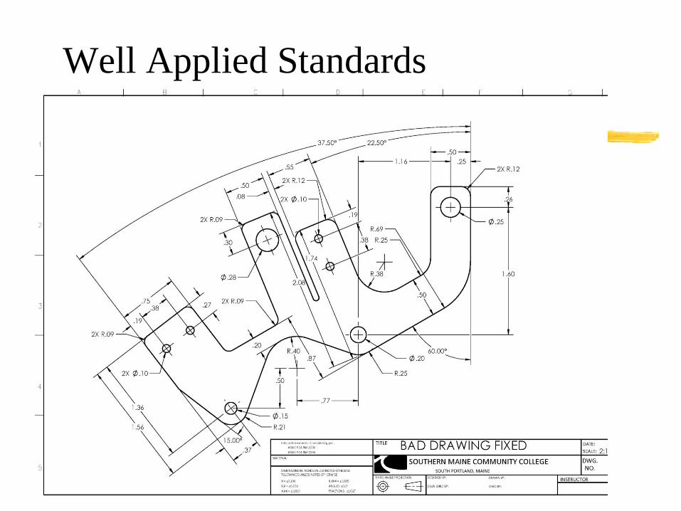
Well Applied Standards

Units and Scale
Rules for Calculations
1. Always use exact conversions NOT rounded or soft
conversions.
a. One inch is equal to exactly 25.4 millimeters
b. One foot is equal to exactly .3048 meters
2. Always include units in all calculations and cancel them
as you go.
1. 1IN = 25.4 mm/IN
2. 1ft = .3048 m/ft

Standard Measurement in U.S. is
Metric and Decimal Inch
•The U.S. officially adopted the metric system in
1866.
•U.S. customary units are defined by their metric
equivalents.
•The foot is legally defined to be exactly 0.3048
meter, making one inch exactly 25.4 millimeters.
•The pound is legally defined to equal exactly
453.59237 grams.

Metric – Length
Length
The standard unit of length in the metric
system is the meter. Other units of length and
their equivalents in meters are as follows:
1 millimeter = 0.001 meter
1 centimeter = 0.01 meter
1 decimeter = 0.1 meter
1 kilometer = 1000 meters

Metric – Length Symbols
1 millimeter = 1 mm
1 centimeter = 1 cm
1 meter = 1 m
1 decimeter = 1 dm
1 kilometer = 1 km

Metric – Length Reference
•1 meter is a little longer than 1 yard or 3 feet
•It is about half the height of a tall adult
•A centimeter is nearly the diameter of a dime
•A millimeter is about the thickness of a dime
•A half inch wrench falls between a 12 mm
and a 13 mm wrench.

Metric – Volume
The standard unit of volume in the metric
system is the liter. One liter is equal to 1000
cubic centimeters in volume.
1 milliliter = 0.001 liter
1 centiliter = 0.01 liter
1 deciliter = 0.1 liter
1 kiloliter = 1000 liters
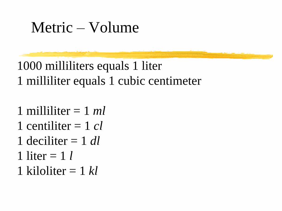
Metric – Volume
1000 milliliters equals 1 liter
1 milliliter equals 1 cubic centimeter
1 milliliter = 1 ml
1 centiliter = 1 cl
1 deciliter = 1 dl
1 liter = 1 l
1 kiloliter = 1 kl

Metric – Volume Reference
For reference,
One liter is a little more than 1 quart
One Gallon is a little less than 4 liters
One teaspoon equals about 5 milliliters

Metric – Temperature
Temperature
•Temperature is expressed in degrees Celsius.
•Water (sea level) boils at 100°Celsius (100°C)
•Water (sea level) freezes at 0° Celsius (0°C)
•(9/5) * X°C+32 = X°F
•(5/9) * (X°F-32) = X°C
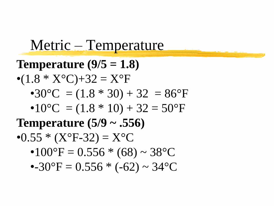
Metric – Temperature
Temperature (9/5 = 1.8)
•(1.8 * X°C)+32 = X°F
•30°C = (1.8 * 30) + 32 = 86°F
•10°C = (1.8 * 10) + 32 = 50°F
Temperature (5/9 ~ .556)
•0.55 * (X°F-32) = X°C
•100°F = 0.556 * (68) ~ 38°C
•-30°F = 0.556 * (-62) ~ 34°C

Prefixes Multiplier
Conversion to meters:
•milli- 0.001 1mm = 0.001m
•centi- 0.01 1cm = 0.01m
•deci- 0.1 1dm = 0.01m
•deka- 10 1dam = 10m
•hecto- 100 1hm = 100m
•kilo- 1000 1km = 1000m

Prefixes Multiplier
•1 meter converted:
•milli- 0.001 1m = 1000mm
•centi- 0.01 1m = 100cm
•deci- 0.1 1m = 10dm
•deka- 10 1m = 0.1dam
•hecto- 100 1m = 0.01hm
•kilo- 1000 1m = 0.001km

Prefixes Above Base
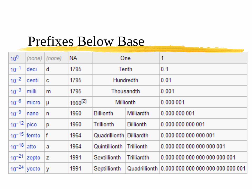
Prefixes Below Base

Selected Factors and FormulasConversion shown in bold are exact and should always be used for maximum precision
(~ means “approximately” and represents values accurate to the precision used)
Length
1 inch = 25.4 millimeters = 2.54 centimeters = .0254 meters (legal U.S.
definition)
1 millimeter = 1/25.4 inches ~ 0.04 inches (0.03937)
1 foot = 304.8 millimeters = .3048 meters (legal U.S. definition)
1 meter ~ 3.28 feet ~ 39.37 inches ~ 39 3/8 inches ~ 1.09 yards
1 mile = 5280 feet = 1609344 mm = 1609.344 meters = 1.609344 km
1 nautical mile ~ 1.15 statute miles ~ 6076 feet
1 rod = 16.5 feet

Selected Factors and FormulasConversion shown in bold are exact and should always be used for maximum precision
(~ means “approximately” and represents values accurate to the precision used)
Area
1 township = 36 sq. miles ~ 6 miles X 6miles
1 acre = 43,560 sq. feet ~ 209 feet X 209 feet ~ .0016 sq. miles
1 sq. mile = 1 section = 640 acres
160 sq. rods = 1 acre

Selected Factors and FormulasConversion shown in bold are exact and should always be used for maximum precision
(~ means “approximately” and represents values accurate to the precision used)
Volume
• 1 cubic foot ~ 7.481 gallons (U.S. liquid)
• 1 gallon ~ .134 cubic feet ~ 231 cubic inch ~ 3.785 liters (legal U.S.
definition)
• 1 liter ~ 0.264 gallon (1 gallon is about 4 liters)
• 1 cubic yard = 27 cubic feet = 46,656 cubic inches ~ 202 gallons
• 1 yard = 1 cubic yard
• 1 inch rain ~ 27,154.28 gallons/acre ~ 17,378,743 gallons/square mile ~ 10"
wet or 12" dry snow resulting in approximately 50% runoff, 20%
evaporation, 20% transpiration, 10% groundwater

Selected Factors and FormulasConversion shown in bold are exact and should always be used for maximum precision
(~ means “approximately” and represents values accurate to the precision used)
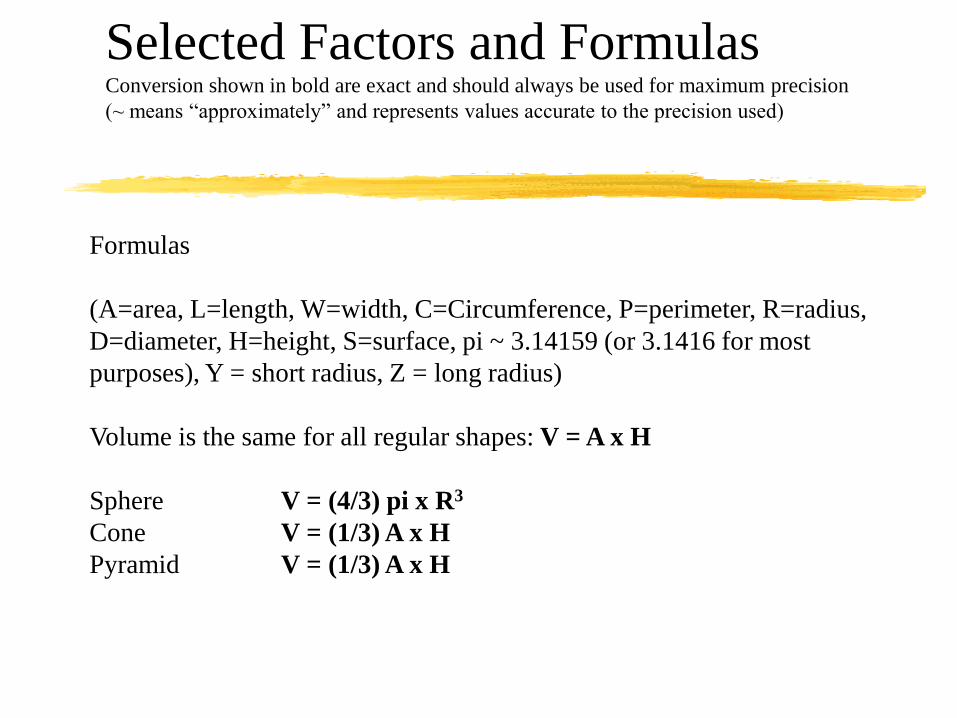
Formulas
(A=area, L=length, W=width, C=Circumference, P=perimeter, R=radius,
D=diameter, H=height, S=surface, pi ~ 3.14159 (or 3.1416 for most
purposes), Y = short radius, Z = long radius)
Area
• Rectangle A = L * W P = 2L + 2W
• Parallelogram A = H * L
• Trapezoid A = H * (L1 + L2)/2
• Triangle A = (L + H)/2
• Circle A = pi x R2 C = pi x D
• Ellipse A = pi x Z x Y
Selected Factors and FormulasConversion shown in bold are exact and should always be used for maximum precision
(~ means “approximately” and represents values accurate to the precision used)
Formulas
(A=area, L=length, W=width, C=Circumference, P=perimeter, R=radius,
D=diameter, H=height, S=surface, pi ~ 3.14159 (or 3.1416 for most
purposes), Y = short radius, Z = long radius)
Volume is the same for all regular shapes: V = A x H
Sphere V = (4/3) pi x R3
Cone V = (1/3) A x H
Pyramid V = (1/3) A x H
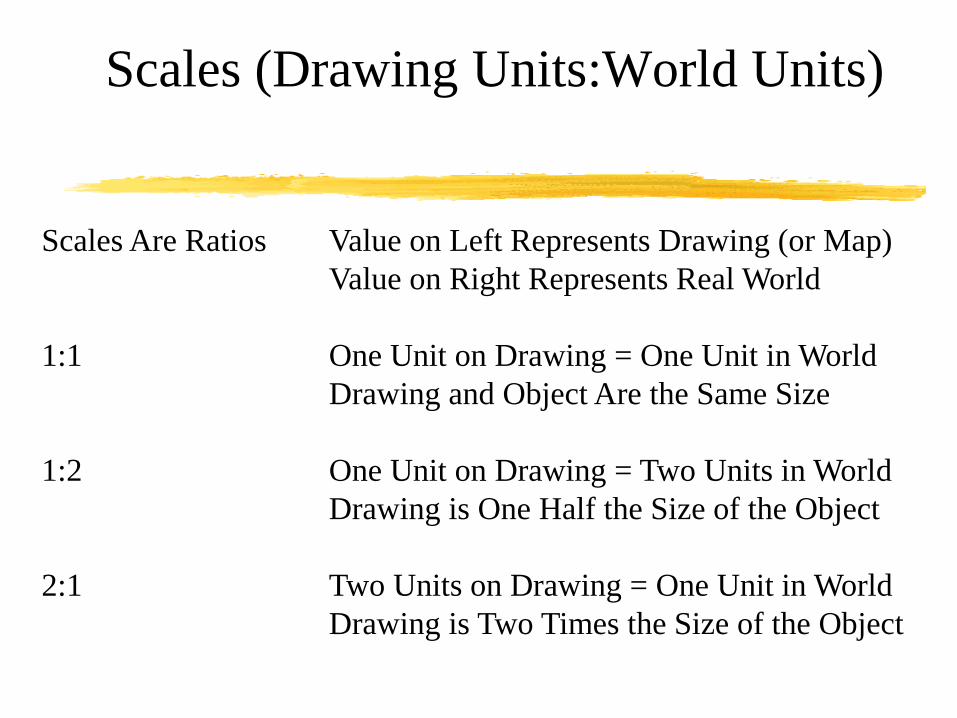
Scales (Drawing Units:World Units)
Scales Are Ratios Value on Left Represents Drawing (or Map)
Value on Right Represents Real World
1:1 One Unit on Drawing = One Unit in World
Drawing and Object Are the Same Size
1:2 One Unit on Drawing = Two Units in World
Drawing is One Half the Size of the Object
2:1 Two Units on Drawing = One Unit in World
Drawing is Two Times the Size of the Object

Scales in Different Disciplines
Design Disciplines That Use Metric Units Show Scales as Ratios
10000:1 500:1 5:1 2:1 1:1
1:10000 1:500 1:5 1:2 1:1
U.S. Mechanical Design Uses Ratios Also But Sometimes Include
8:1 4:1 1:4 1:8
U.S. Architectural Design Uses Ratios of Various Inches to 1 Foot
1/8”=1-0’ 1/4”=1.0’ 1”=1-0’ 3”=1-0’
U.S. Civil Design Uses Ratios of 1 Inch to Various Feet
1”=100’ 1”=1200’ 1”=5000’ 1”=10,000’

Orthographic Projection

Glass Box

Glass Box -- Unfolded

View Selection – First/Third Angle

View Selection – First/Third Angle

View Selection – First/Third Angle

Orthographic (Straight Line) Projection

Orthographic (Straight Line) Projection
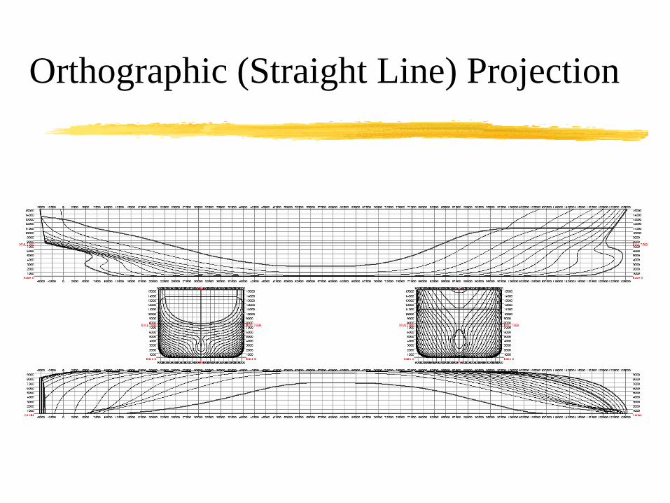
Orthographic (Straight Line) Projection

View Selection – Front in True Shape

View Selection – Front Most Detail

View Selection – Horizontal Format

View Selection – Fewest Hidden

View Selection – Visually Stable

Alphabet of Lines

Line
Conventions

Alphabet of Lines
Thick Lines

Alphabet of Lines
Thin Lines
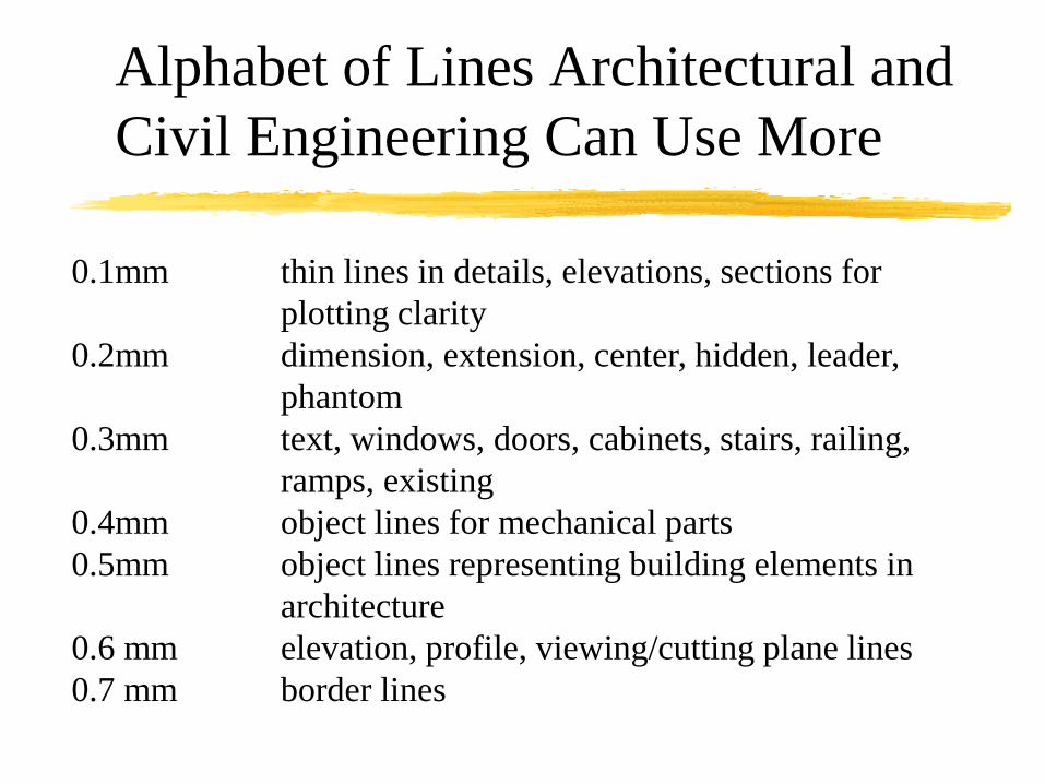
Alphabet of Lines Architectural and
Civil Engineering Can Use More
0.1mm thin lines in details, elevations, sections for
plotting clarity
0.2mm dimension, extension, center, hidden, leader,
phantom
0.3mm text, windows, doors, cabinets, stairs, railing,
ramps, existing
0.4mm object lines for mechanical parts
0.5mm object lines representing building elements in
architecture
0.6 mm elevation, profile, viewing/cutting plane lines
0.7 mm border lines
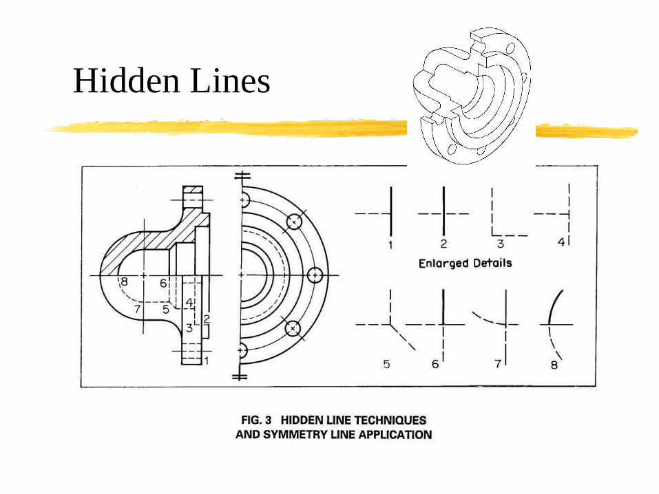
Hidden Lines

Section Lines

Section Lines

Section Lines

Section Lines
Conventional Break with dimension shown as "not to scale."

Section Lines
3
21
10
An assembly section showing the use of different symbols for iron, steel
and bronze. Solid fasteners are not sectioned when shown in length
(parts 6, 8, 9, and 10), only in an end view (part 1).
4
5
6
7
8
9

Section Lines - Assembly

Section Lines - Assembly

Section
Lines

Sheet Sizes (1 IN = 25.4mm)
(~ means “approximately”)
Size ANSI Architectural Millimeters (~Inches)
U.S. ISO
A A4 11 X 8.5 12 X 9 297x210 (~11.7x8.3)
B A3 17 X 11 18 X 12 420x297 (~16.5x11.7)
C A2 22 X 17 24 X 18 594x420 (~23.4x16.5)
D A1 34 X 22 36 X 24 841x594 (~33.1x23.4)
E A0 44 X 34 48 X 36 1189x841(~46.8x33.1)
A, C, and E have same proportions
B, and D have the same proportions

Text Style and Height
Font – Drawings Use a Sans-Serif Font (Single Stroke Gothic)
ROMANS ARIAL CALIBRI
Case – Title Block Lettering Should be Upper Case
Sentences or Paragraphs of Text Should Be Sentence Case
Height – Generally Two Text Heights Are Used on Drawings
Large Text and Small Text at a 2:1 Ratio
Titles/Drawing Numbers .24” (.2” Sometimes) 6mm
Everything Else .12” (.1” Sometimes) 3mm
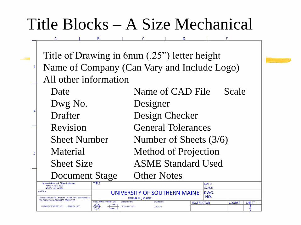
Title Blocks – A Size Mechanical
Title of Drawing in 6mm (.25”) letter height
Name of Company (Can Vary and Include Logo)
All other information
Date Name of CAD File Scale
Dwg No. Designer
Drafter Design Checker
Revision General Tolerances
Sheet Number Number of Sheets (3/6)
Material Method of Projection
Sheet Size ASME Standard Used
Document Stage Other Notes

Title Blocks – B Size Mechanical
Title Block in Lower Right Corner
Revisions Above or Left of Title Block
Bill of Materials Upper Right Corner

Architectural Title
Blocks
Can be Horizontal in
Bottom Right Corner Like
Mechanical
Can Be Vertical on Right
Side of Drawing Sheet

DimensioningASME Y14.5M-1994 ASME Y14.5M-2009

ASME Y14.5M-1994 and -2009
Dimensioning Practices
Geometric
Dimensioning and
Tolerancing (GD&T)
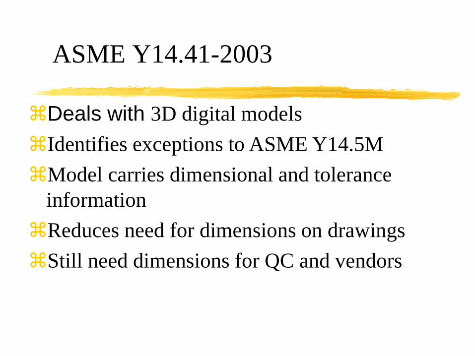
ASME Y14.41-2003
Deals with 3D digital models
Identifies exceptions to ASME Y14.5M
Model carries dimensional and tolerance
information
Reduces need for dimensions on drawings
Still need dimensions for QC and vendors

1.1 General
This standard identifies uniform practices
for engineering drawings
The standard doesn’t apply to:
Architectural Drawings
Civil Engineering Drawings
Welding Symbols on Drawings
AWS has it’s own standard for welding symbols
ANSI/AWS A2.4, Symbols for Welding and
Nondestructive Testing
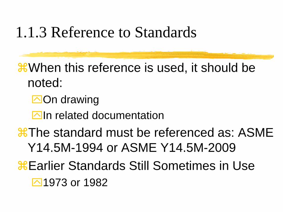
1.1.3 Reference to Standards
When this reference is used, it should be
noted:
On drawing
In related documentation
The standard must be referenced as: ASME
Y14.5M-1994 or ASME Y14.5M-2009
Earlier Standards Still Sometimes in Use
1973 or 1982

Standard is Metric and Decimal Inch
•The U.S. officially adopted the metric system in
1866.
•U.S. customary units are defined by their metric
equivalents.
•The foot is legally defined to be exactly 0.3048
meter, making one inch exactly 25.4 millimeters.
•The pound is legally defined to equal exactly
453.59237 grams.

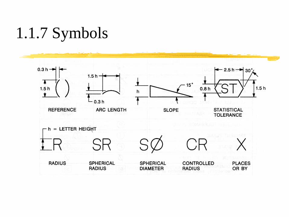
1.1.7 Symbols
Use symbols where appropriate
Use equivalent terms or abbreviations
where symbols are not appropriate
Symbols are preferred since they are
identical to the ISO standard

1.1.7 Symbols
1.1.7 Symbols

1.3 Definitions - selected
Dimension -- a numerical value defining
Size
Location
Geometric Characteristic
Surface Texture
Basic Dimension – theoretically exact
Reference Dimension – for information only

1.4 Fundamental Rules
Dimensions shall clearly define intent
Each dimension must have a tolerance
Directly -- limit, bilateral or unilateral
Indirectly – general note or title block note
Decimal places can have tolerance significance
Exceptions:
Reference, Basic, Maximum, Minimum, Stock
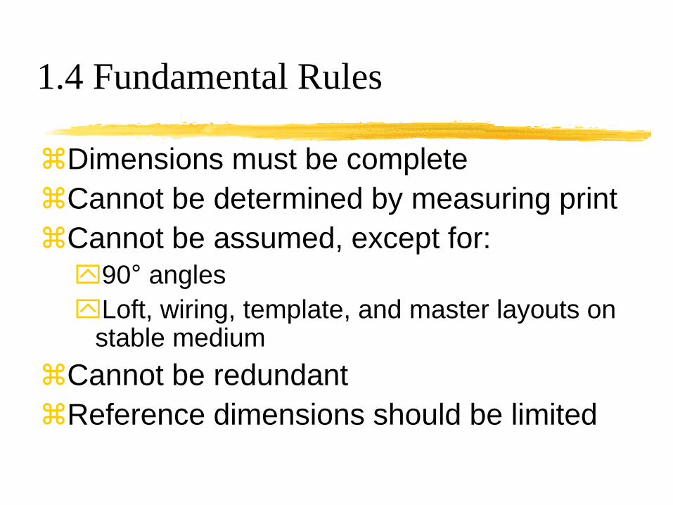
1.4 Fundamental Rules
Dimensions must be complete
Cannot be determined by measuring print
Cannot be assumed, except for:
90° angles
Loft, wiring, template, and master layouts on stable medium
Cannot be redundant
Reference dimensions should be limited

1.4 Fundamental Rules
Dimensions must be clearly arranged
Dimensions must be subject to only one
interpretation
Manufacturing methods should not be part
of dimensioning unless essential to
engineering requirements
Hole Size, Location, and Surface Finish, but
not how to manufacture the hole
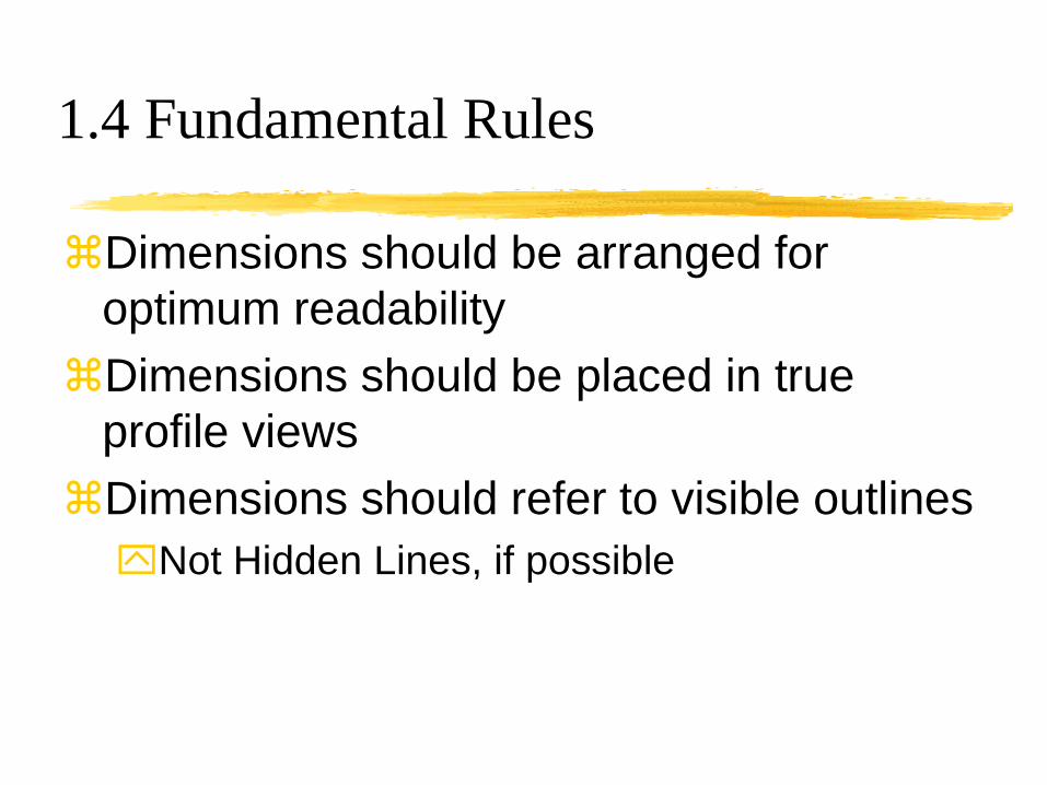
1.4 Fundamental Rules
Dimensions should be arranged for
optimum readability
Dimensions should be placed in true
profile views
Dimensions should refer to visible outlines
Not Hidden Lines, if possible

1.4 Fundamental Rules
Angles without dimensions are 90°
Dimensions apply at 20°C (68°F)
Dimensions apply in free-state condition
Dimensions and tolerances apply only at
the drawing level where they’re specified
Every feature must have a tolerance
Dimensions that locate it (specific or general)
Feature Control Frame

1.5 Units of Measurement
SI (Metric) linear units are millimeters
Customary U.S. linear units are decimal
inch, not fractions -- fractions are used
only as nominal sizes e.g. 1/2-20 UNC
Units are not placed on dimensions when
all are the same – note in title block
When mixed, add IN or mm as suffix to
exceptions

1.5 Units – Angles
Decimal
degrees or
Degrees
minutes and
seconds

1.6 Types – Metric
Metric dimensions have leading, but not following zeros
Except in bilateral or limit tolerances

1.6 Types – Decimal Inch
Decimal Inch
dimensions use
trailing, but not
leading, zeros
Same number
of decimal
places as
tolerance

1.7.1.1 Dimension Lines
Dimension lines have arrowheads
Preference for breaking line for numeral
If not broken, numeral goes above line
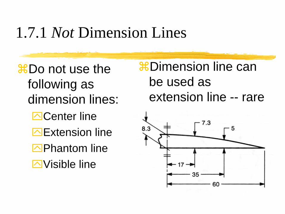
1.7.1 Not Dimension Lines
Do not use the
following as
dimension lines:
Center line
Extension line
Phantom line
Visible line
Dimension line can
be used as
extension line -- rare
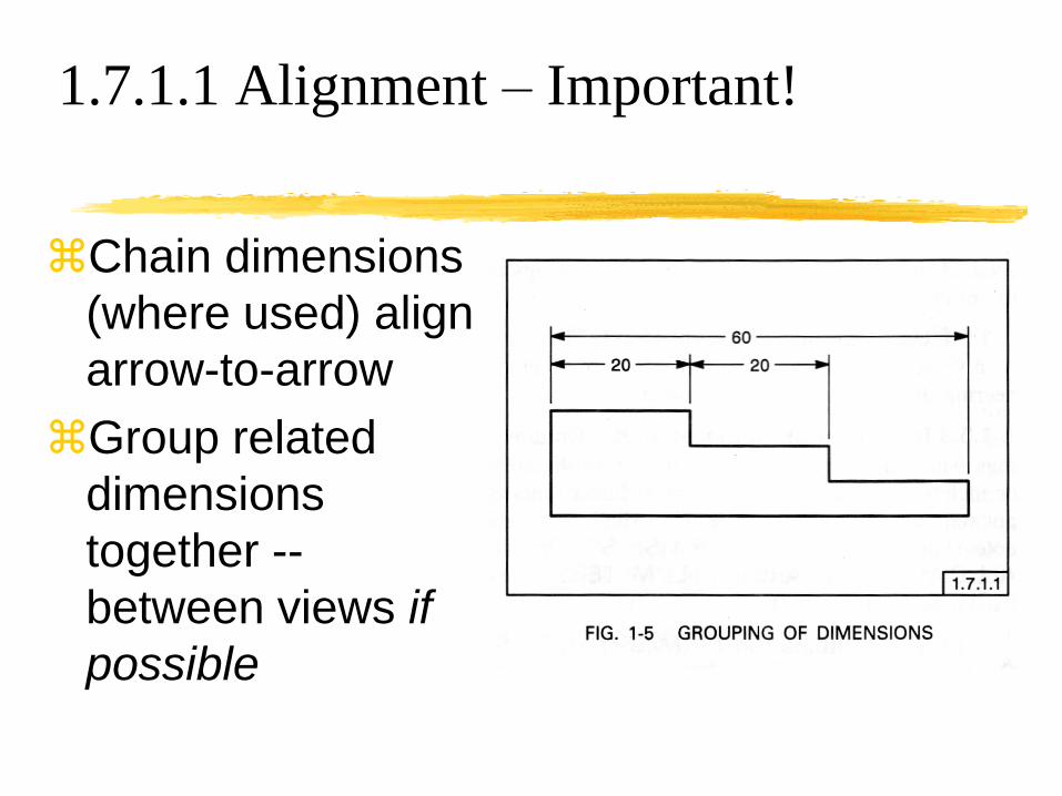
1.7.1.1 Alignment – Important!
Chain dimensions
(where used) align
arrow-to-arrow
Group related
dimensions
together --
between views if
possible

1.7.1.2 Spacing Dimensions
Dimension spacing
First ≥10mm from
part
Subsequent ≥ 6mm
Modify for readability
if necessary
Extension line gap
~1.5mm (~.06IN)
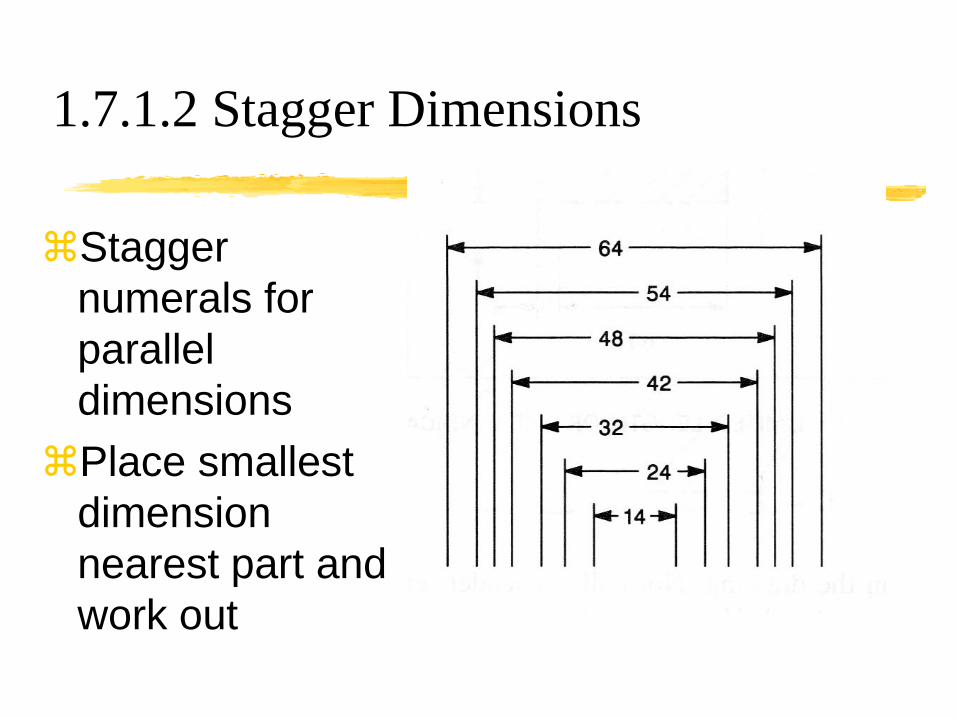
1.7.1.2 Stagger Dimensions
Stagger
numerals for
parallel
dimensions
Place smallest
dimension
nearest part and
work out

1.7.2 Extension Line
Extension lines
extend a feature
Need a gap (1.5)
Normally 90° to
dimension line
Oblique OK
when needed

1.7.2 Crossing Extension Line
Avoid Crossing
Dimension Lines
Extension lines
Do not break
dimension lines
Break extension
lines only when
crossing arrow

1.7.3 Chain Lines
Use chain line to indicate limits for additional treatment
Dimension location if not obvious
Designate area with section lines and chain line (thick center linetype)

1.7.4 Leaders
A leader with
an arrowhead
points to an
edge
A leader with
a dot points to
a surface

1.7.4.1 Leader Directed Dims
Avoid complicated
single leaders
…but, also avoid
multiple leaders by
using times (X)

1.7.4.2 Circle and Arc
Leaders used to dimension circles or arcs must be radial (point towards or through the center)
Arrowheads never stop at center

1.7.5 Orientation – Notes (U.S. Only)
Notes must be
horizontal (parallel
to top of sheet)
ISO uses aligned
Dimensions with
lines and
arrowheads are
horizontal

1.7.5 Orientation – Baseline
Baseline
dimensions
are aligned
to their
dimension
lines from
bottom or
right

1.7.6 Reference Dimensions
Reference
dimensions
are placed in
parentheses
and used to
avoid over-
dimensioning

1.7.7 Overall Dimensions
If intermediate
dimensions
are more
important than
the overall, it
is a reference
dimension

1.7.9 Not-to-Scale – Hard Copy Original
Paper drawing dimension value changed
Geometry is not updated
Not-to-scale dimension is underlined

1.7.9 Not-to-Scale – Electronic Data
“Where the sole authority for the product
definition is a dataset prepared on a
computer graphics system, agreement
shall be maintained between the defining
dimension and the graphics presentations
of the feature in all views. The defining
dimension and the true size, location, and
direction of the feature shall always be in
complete agreement.”

1.8.1 Diameters
Use the
diameter or
spherical
diameter symbol
Concentric
cylinders can be
longitudinal –
often preferred

1.8.2 Radii
Use the radius,
spherical
radius or
controlled
radius symbol
Arrowhead
never goes to
center
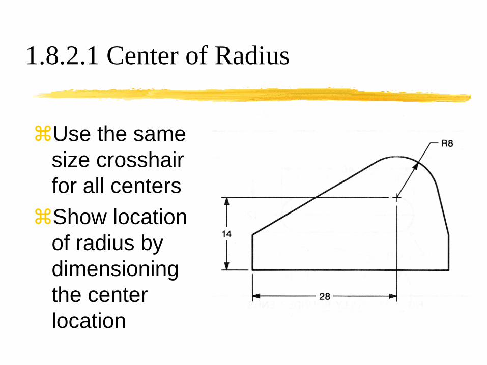
1.8.2.1 Center of Radius
Use the same
size crosshair
for all centers
Show location
of radius by
dimensioning
the center
location
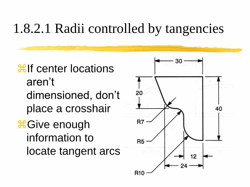
1.8.2.1 Radii controlled by tangencies
If center locations
aren’t
dimensioned, don’t
place a crosshair
Give enough
information to
locate tangent arcs

1.8.2.2 Forshortened radii
Arrowhead
part of
foreshortened
dimension
must be radial
Dimension
must be
foreshortened

1.8.3 Chords, Arcs and Angles
Chords are linear dimensions
Arc length dimension requires a symbol
Angle between radii uses arc dimension lines

1.8.4 Rounded Ends (not slots)
Fully rounded -
radius not
specified
Partially rounded -
radius specified
Rounded corner –
radius specified

1.8.7 Tangent Arc Outlines
Give all radius
values
Locate necessary
centers
Tangencies
determine others(some linear dimensions
not shown in example)
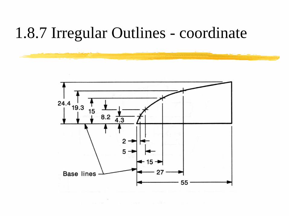
1.8.7 Irregular Outlines - coordinate
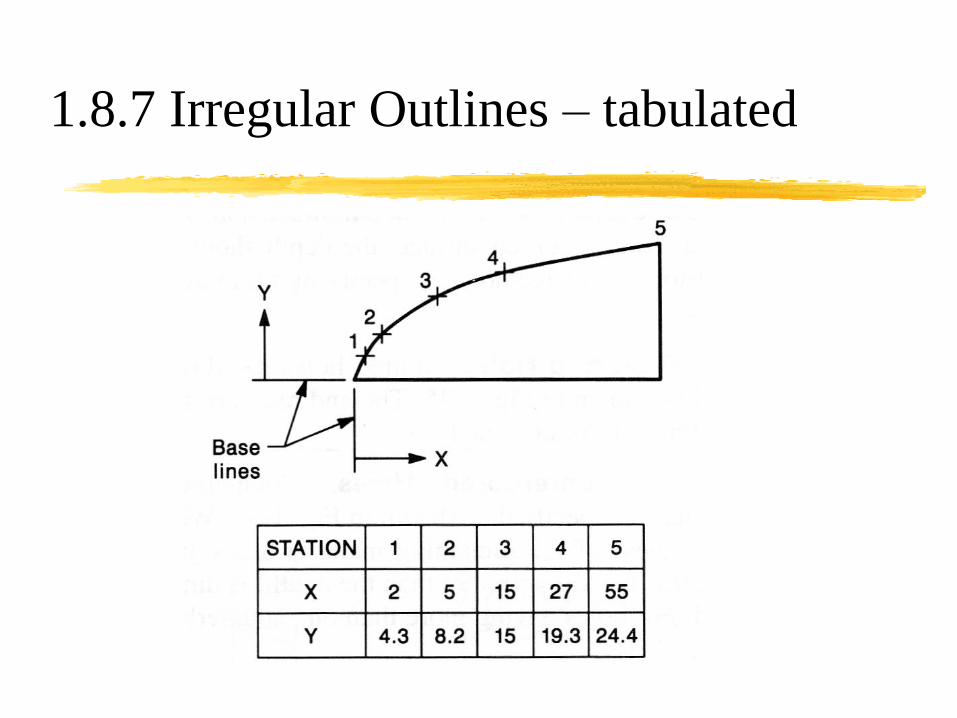
1.8.7 Irregular Outlines – tabulated

1.8.9 Round Holes
Use THRU only when unclear
Depth is depth @ full diameter
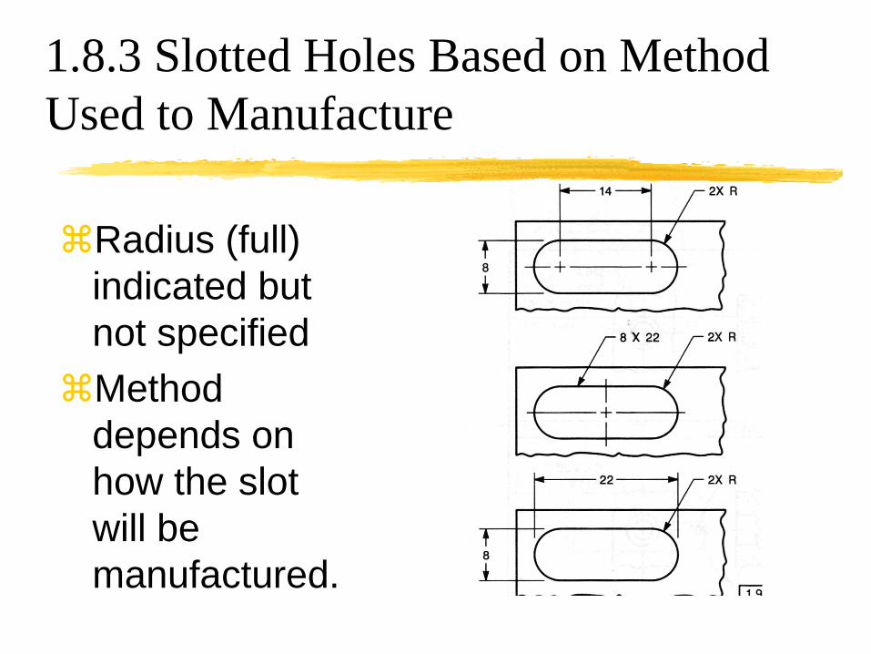
1.8.3 Slotted Holes Based on Method
Used to Manufacture
Radius (full)
indicated but
not specified
Method
depends on
how the slot
will be
manufactured.

Types of Holes
Counterbore (Blind) Counterdrill Countersink Spotface
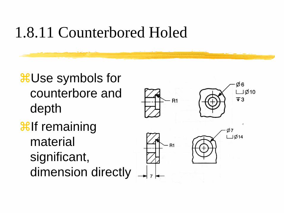
1.8.11 Counterbored Holed
Use symbols for
counterbore and
depth
If remaining
material
significant,
dimension directly

1.8.11 Multiple Counterbore
Two
methods,
starting
with
smallest
hole
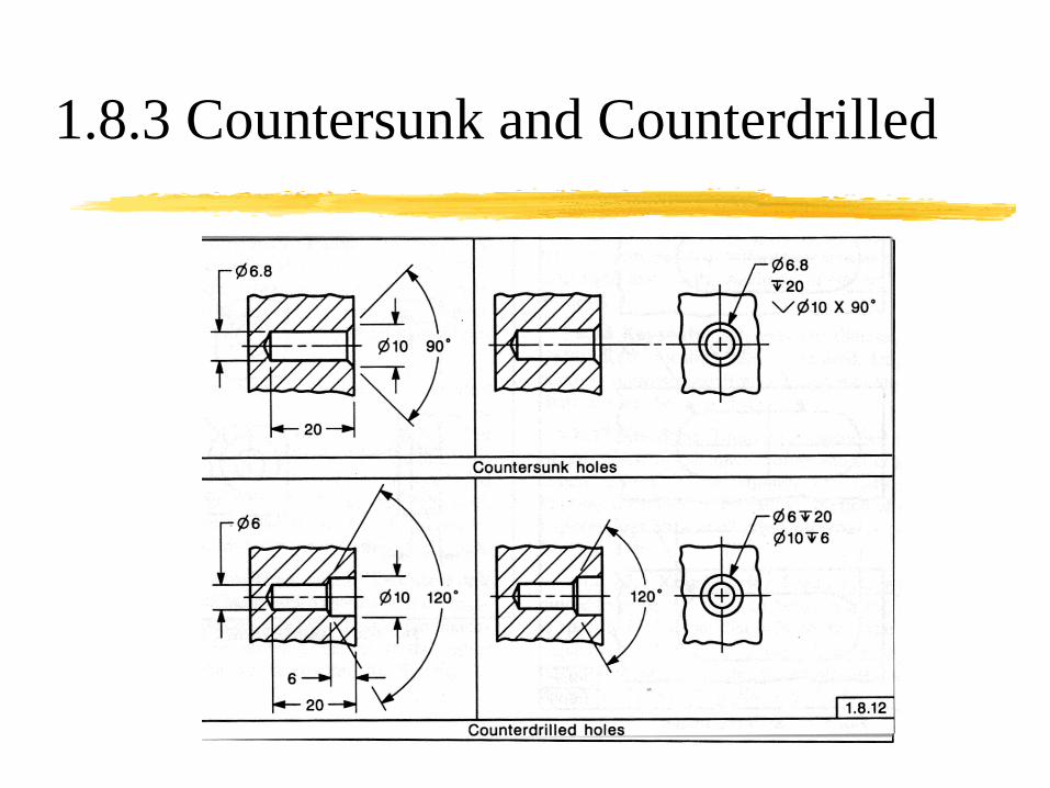
1.8.3 Countersunk and Counterdrilled

1.8.3 Spotface
Spotface uses the
same format as
counterbore, but
with no depth given
Depth is enough to
clean up or to
remove irregular or
cast surface
SF
2009
1994

1.8.15 Chamfers

1.8.3 Keyways and keyseats
Keyways from
opposite side of hole
Keyseats from
opposite side of shaft
Actual sizes calculated
or taken from tables

1.8.3 Keyways and keyseats

1.9.1 Rectangular Coordinate (baseline)
Tolerance Zones are Rectangles

1.9.2 Rectangular Coordinate Arrowless
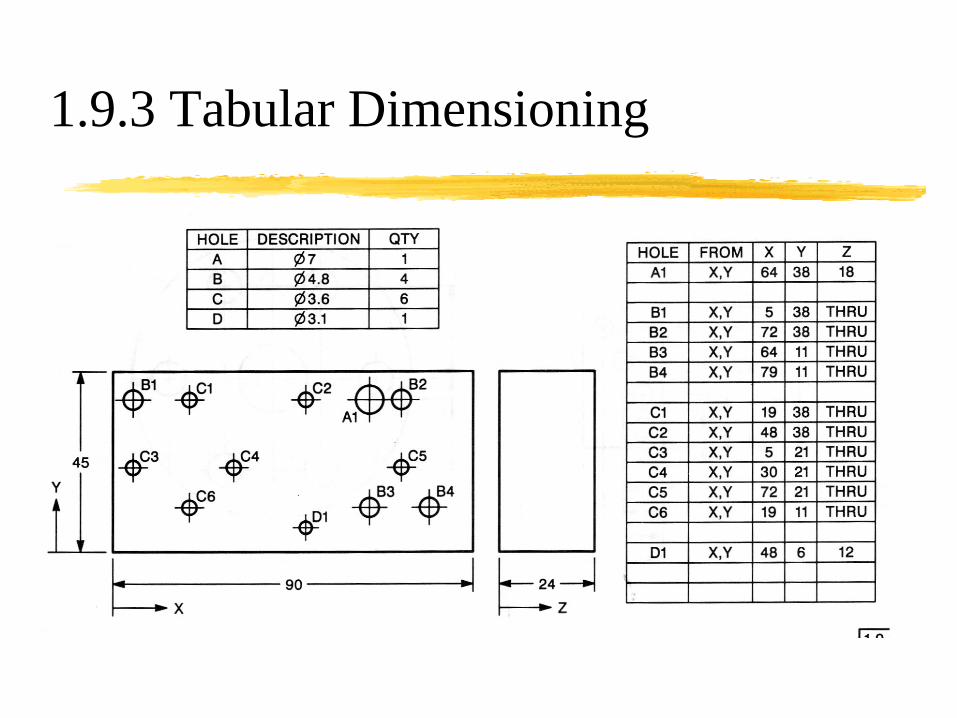
1.9.3 Tabular Dimensioning

1.9.4 Polar Coordinate
Requires both a
radial linear
dimension and
an angular
dimension to
locate each
feature

1.9.4 Polar Coordinate
Tolerance zone
is keystoned
and changes
size with
distance from
center

1.9.5.1 Repetitive Features
Use the X Symbol

2.1 Dimensional Tolerances
Limit Tolerances

2.1 Dimensional Tolerances
Plus/Minus Tolerances

2.6 Accumulation of Tolerance Error
Chain Dimensioning

2.6 Accumulation of Tolerance Error
Baseline Dimensioning

2.6 Accumulation of Tolerance Error
Direct Dimensioning

2.7 Features of Size
Rule #1

2.12 Tolerance Linear/Angular
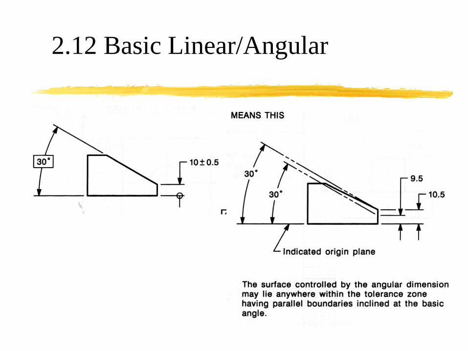
2.12 Basic Linear/Angular

2.7 Features of Size

2.14 Flat Tapers

2.14 Conical Tapers

2.14 Conical Tapers – Reference Dims

2.15.1 Radius not Controlled

2.15.1 Controlled Radius

Summary of Rules – Bad Practice
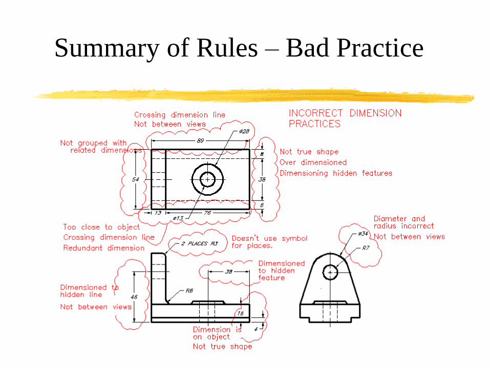
Summary of Rules – Bad Practice

Summary of Rules – Better Practice