technical documentation lift advanced - home - hettich · 2017-04-04 · lift advanced 7 2.3 gas...
TRANSCRIPT

1
Technical Documentation Lift Advanced

Lift Advanced
24.03.2011 / HFT / CM / DW 2
1 Introduction .................................................................................................................... 4 2 Basic Information ......................................................................................................... 5
2.1 Hinge Recommendations ............................................................................................ 5 Lift Advanced HF ........................................................................................................... 5 Lift Advanced HK .......................................................................................................... 5
2.2 Usage of Aluminium Fronts ........................................................................................ 5 19mm Aluminium Framed Fronts ............................................................................. 5 45mm / 55mm wide Aluminium Framed Fronts ................................................... 6
2.3 Gas Pressure Springs .................................................................................................... 7 Description of the Component .................................................................................. 7 Technical & Logistical Information .......................................................................... 7 Assignment Article Numbers & Spring Force ........................................................ 9 Selection of the Correct Spring ................................................................................. 9 Mounting of the Gas Pressure Spring ..................................................................... 9 Disfitting of the Gas Pressure Spring .................................................................... 10
3 Fitting ............................................................................................................................. 12 3.1 Preparation of Fitting ................................................................................................ 12
Contents Fittings Set ................................................................................................. 12 Preparation of the Cabinet ....................................................................................... 12 Preparation of the Flap(s) ......................................................................................... 12 Preparation of Cross Member (only for Lift Advanced HL & HS) ................... 13
3.2 Fitting Lift Advanced HF ........................................................................................... 15 Usage of Spacers ......................................................................................................... 21
3.3 Fitting Lift Advanced HK ........................................................................................... 23 3.4 Fitting Lift Advanced HL & HS ................................................................................ 25
4 Adjustment ................................................................................................................... 30 4.1 Adjustment of Gaps .................................................................................................... 30 4.2 Adjustment of the Closing Damper ........................................................................ 30 4.3 Adjustment of the spring force ............................................................................... 31 4.4 Adjustment of the Opening Angle Stop ................................................................ 31
5 Description of Defects and their Correction ........................................................ 33 5.1 All Variants ................................................................................................................... 33
Distortion of the fitting base plate ........................................................................ 33 5.2 Lift Advanced HF ......................................................................................................... 34
Top flap closes properly, bottom flap tilts frontward ....................................... 34 Fitting arms are bent outwards, arms eventually grinding in the cabinet .. 36 Flap does not close correctly ................................................................................... 37 Flaps close very loudly ............................................................................................... 38
5.3 Lift Advanced HK ........................................................................................................ 39 Flap is tilted in front of the cabinet / Flap does not close properly ............. 39 Fitting arms bend outwards ..................................................................................... 40
5.4 Lift Advanced HS / HL ................................................................................................ 41 Fitting arms grind against the cabinet ................................................................. 41

Lift Advanced
3
Flaps stays tilted in front of the cabinet / Flap does not close correctly .... 42 Fitting arm collides with the cabinet top panel when open (only HS) ........ 43
6 Others ............................................................................................................................. 44 6.1 Location of the contact points of the gas pressure springs ............................ 44 6.2 Identification of the Fittings when fitted .................................................................... 45

Lift Advanced
4
1 Introduction The handbook is divided into several parts and should aim to represent all the aspects of the Lift Advanced series in a clear, comprehensive and descriptive manner. Covering everything from mounting to fine adjustment and a catalogue of defects, this document should serve as an aid to answer any questions quickly and substantially. Information which is already given in the catalogue documents (e.g. hole pattern, calculation of hole positions, etc.) are not again listed here. Symbols used
Tips & Tricks
Attention! Important note!
Related information

Lift Advanced
5
2 Basic Information
2.1 Hinge Recommendations
Lift Advanced HF For this fitting, hinges with an opening angle of 110° should be used (e.g. Intermat 9943). The application of Sensys is possible.
Lift Advanced HK For this fitting, hinges with an opening angle of 95° (e.g. Intermat 9936) or 110° (e.g. Intermat 9943) can be used. The maximum opening angle of the flap is limited to approx. 85° through the flap fitting. The application of Sensys is possible for applications as listed below and enables a gentle closure of the flap, especially large flaps.
Internal cabinet height Weight Sensys?
276 - 360 From 12.4kg OK
360 - 720 All weights OK
2.2 Usage of Aluminium Fronts
19mm Aluminium Framed Fronts
Holes for the adapter at least 42 mm away from the frame top edge otherwise they will collide with the connecting angle of the aluminium frame. The result of this is that specific configurations cannot be realised in case of a HF-flap with unequally sized flaps.

Lift Advanced
6
Depending on the overlay, it can happen that there is a gap between the frame and the adapter. The below given table shows the assignment of the possible lateral overlays in gap dimensions ranging from 0mm to 5mm for the different fittings version. Gap
min = 0mm max = 5mm HF 14.5 19.5 HL 14.5 19.5 HS 14.5 19.5
For Lift Advanced HK, due to the length of the adapter, the gap dimension of 0mm cannot be achieved.
HK Gap
min = 2.8mm max = 5mm Overlay 10.8 13
Front adapter for Lift Advanced HF, Lift Advanced HL, Lift Advanced HS
Front adapter for Lift Advanced HK
45mm / 55mm wide Aluminium Framed Fronts Preparation of this aluminium profile for Lift Advanced by HFT is currently NOT possible. For connecting the fitting to a 45mm or 55mm wide frame so-called blind rivet nuts M6 must be flush mounted in the respective drilling positions in the frame. ATTENTION: Drilling positions should not be in the area of the aluminium frame connecting angle!

Lift Advanced
7
2.3 Gas Pressure Springs
Description of the Component
Technical & Logistical Information Gas pressure springs are filled with gas (nitrogen) and oil. The oil has several uses. It helps to lubricate the piston rod. It also collects on top of the seal, forms an additional barrier between the interior of the spring and the surrounding and like this helps keeping gas pressure loss low. However, this can only work, if the piston rod faces downwards (see image above). Therefore, storage and installation of the spring must be done with the piston rod facing downwards. ATTENTION: Storage ALWAYS with piston rod facing downwards, NEVER with piston rod facing upwards (otherwise loss of pressure may occur!) ATTENTION: Mounting ALWAYS with piston rod facing downwards (otherwise loss of pressure may occur!) (See photo page 8) Storage time should be kept as short as possible because the durability could be affected by long or improper storage.

Lift Advanced
8
Correct! Wrong!
Other technical information: Operating temperature between –30°C and +80°C Oil for lubrication of the piston rod, sealing of the sealing gap and
dampening of opening action Due to technical reasons there can be tolerances of the spring force of up
to 15%, these possible fluctuations will be considered in the dimensioning of the spring strength
The gas pressure spring cannot be completly sealed to the outside, approximately 2-3% of the gas escapes from the spring every year (“Permeation”)
Gas pressure spring does not hold the flap closed; the spring always aims to open the flap
If the selection table specifies two spring strengths, the stronger spring has to be chosen
“6582YG” = Part number “0450N” = Details of spring force
“317/09” = Production day / Production year
See also references to complaints that have arisen.

Lift Advanced
9
Assignment Article Numbers & Spring Force Catalogue number
Spring force Catalogue number
Spring force
9079618 150 N 9079635 550 N 9079619 200 N 9079637 600 N 9079622 250 N 9079644 650 N 9079624 300 N 9079645 700 N 9079626 350 N 9079647 750 N 9079628 400 N 9079650 800 N 9079630 450 N 9079651 850 N 9079632 500 N
Selection of the Correct Spring The required spring force depends on the chosen fitting variant, the inner cabinet height and the weight of the flap. In the catalogue documentation, tables which allow the selection of the correct spring can be found. If the selection table specifies two springs, then the stronger spring has to be chosen. ATTENTION: For selection of the correct spring strength, the exact weight of the front including the handle must be considered.
Mounting of the Gas Pressure Spring The gas pressure springs are clipped on to the fitting with ball cups fitted on ball pins. The ball cup is locked in position on the ball pin by means of steel spring. The gas pressure spring must be fitted with the piston rod facing downwards; otherwise an increased loss of pressure and premature malfunction of the spring is possible (see photo S.10)

Lift Advanced
10
Correct! Wrong!
Disfitting of the Gas Pressure Spring To disassemble the spring, the steel spring is loosened at the top ball pin using a fine screwdriver and the ball cup is removed from the pin. ATTENTION: Hold the flap in place, risk of injury! The spring is turned downwards and the steel spring of the lower ball cup is loosened and the spring is removed. (See photos page 11) ATTENTION: To use the spring, if needed, in another fitting, the spring steel should not be slipped fully from the ball cup.

Lift Advanced
11

Lift Advanced
12
3 Fitting
3.1 Preparation of Fitting
Contents Fittings Set
4x brass expanding dowel with hex head for holes Ø10x12mm, to drive into the flap
4x M6-threaded screw with hex socket in the head, to connect the fitting arm to the flap
6x Euro screws with Pozidriv for holes Ø5x12, to screw the fitting into the cabinet
2x allen keys in the required sizes
Preparation of the Cabinet Drill the holes (Ø5x12) for securing the fitting into the cabinet.
TIP: Use the drilling template included in the box If required, drill holes for the mounting plates in the cabinet and fix the
mounting plates (Lift Advanced HF & HK) ATTENTION: Position the hinge min. 90 mm from the inner edge of the cabinet side!
Preparation of the Flap(s) Calculate hole positions (see catalogue documentation) Drill the holes (Ø10x12)
TIP: The more accurate the holes are drilled, the lesser adjustments are required later. In case of inaccurate holes, the flaps can maybe not be brought to the correct position by using the adjustment possibility given in the fitting.
If required, drill holes for the hinge and mount the hinge (Lift Advanced HF top flap & HK)

Lift Advanced
13
ATTENTION: Position the hinge min. 90 mm from the inner edge of the cabinet side!
Flush insertion of the brass expanding dowels ATTENTION: Dowels must be absolutely flush inserted. Better a little too deep than projecting outside!
Screw in the M6-screws into the dowel far enough that the dowels expand (Expanding the dowel will prevent the dowel from rotating during the subsequent fitting)
Screw out the M6-screws again until only a few turns of the screw thread remain in the dowel (for the top flap HF and flap HK remove the screws)
For Lift Advanced HF, if required, fit spacer for centre joint (see page 21 “Usage of Spacers”)
Preparation of Cross Member (only for Lift Advanced HL & HS) For cabinet widths of 600mm, 1200mm and 1800mm, cross members are
available (the cross member automatically adjusts to different side panel thicknesses from 16-19mm)

Lift Advanced
14
For other cabinet widths, the mid section of the cross member must be cut to length (cabinet width– 290mm)

Lift Advanced
15
3.2 Fitting Lift Advanced HF
All the fitting steps shown are to be executed in the sequence presented below. Ignoring any fitting step can lead to severe damages and defect of the fitting or the fitting not being properly adjustable. ATTENTION: The fitting steps, especially 4, 6 and 8 are to be followed NECESSARILY.
1 Fix the fitting into the cabinet
2 Check whether spacer must be used
Hole position “J“ of the bottom flap smaller than 65mm Fit the spacer on the flap (see also page 21 “Usage of Spacers “)
3 Mount the top flap to the cabinet with the hinges

Lift Advanced
16
4
Adjust the joints of the top flap at the hinges ATTENTION: It is absolutely necessary that the joint of the top flap is adjusted at this point during the fitting!
TIP: Use stop attachments as this will simplify the adjustment of the joint. Check the fit of the flap by pressing the corner of the flap from the front; in case of air between the flap and the cabinet, readjust the hinge.
5
Hold up the flap and clip on the gas pressure springs ATTENTION: Piston rod pointing downwards!
6 Screw the fitting arm to the
top flap (M6-screws in expanding dowel) ATTENTION: It must be ensured that the top flap can be opened fully (min. 110°) and does not get jammed in by the top panel (in this case: change the depth adjustment of the hinge)

Lift Advanced
17
7 Close the flap ATTENTION: When closing, there could be crack sound, because the joint screws have not been tightened (see next step in fitting)
8
Tighten the screw on both sides in the joint! ATTENTION: This fitting step is extremely important. If the screw is not fixed or not tightened sufficiently, it will result in increased wear and tear of the joint and the premature breakdown of the fitting! (see also defect pictures, page 33)
9 Open the flap. ATTENTION: Risk of injury due to very forceful opening because the bottom flap is not yet installed!
10 Hang the bottom flap in the fitting with the pre-mounted screws.

Lift Advanced
18
11 Tighten the screws
Adjust the joint of the bottom flap
12 Height adjustment
+/- 2mm
1. Loosen the mounting screws
2. Lower the flap: turn out the set screw
2. Raise the flap: Screw-in the set screw

Lift Advanced
19
3. Tighten the screws
ATTENTION: While using spacers (see page 21), the bottom flap must be set as high as possible so that no air remains between the spacers.
13 Lateral adjustment
Screw-in the set screw: Fitting is pushed to the outside.
Move the flap to the right: Screwin the set screw at the left fitting arm, screw out the set screw at the right fitting arm
Move the flap to the left: Screw in the set screw at the right fitting arm, screw out the set screw at the left fitting arm

Lift Advanced
20
14
Tilt adjustment

Lift Advanced
21
Usage of Spacers To prevent the flap connection from overstretching during opening (by pulling the handle, the bottom flap is pushed backwards in the central joint), spacers must be placed in the central joint. This is required if the bottom flap can not support itself against the fitting arm, which might be the case with very high cabinets or unequally divided flaps. The spacers are included with the fitting Lift Advanced HF for the cabinet heights 700 – 770mm (Article 9079614) and 770 – 925mm (Article 9079615) and must be installed if the position of the upper hole on the bottom flap (value “J” see catalogue) is less than 65 mm from the upper edge of the flap. The spacers can only work effectively if no air is left between the angles. Therefore bottom flap has to be adjusted upwards until the spacers are pressed against each other. The overstretching of the bottom flap connection leads to wear and tear of the tilt adjustment and after some time the bottom flap no longer stays straight in front of the cabinet, but tilts forward at the top edge ( see also defect picture, page 33).

Lift Advanced
22
Bottom flap is supported by the fitting arm, spacer not required.
Bottom flap cannot support itself on the fitting arm, spacer required.
With the help of the spacer, the central reveal can be defined and the bottom flap cannot be overstretched.

Lift Advanced
23
3.3 Fitting Lift Advanced HK
All the fitting steps shown are to be executed in the sequence presented below.
1 Fix the fitting into the cabinet
2 Mount the top flap to the cabinet with the hinges
3 Adjust the joints of the flap at the hinges

Lift Advanced
24
4
Hold up the flap and clip-on the gas pressure spring ATTENTION: piston rod points downward!
5
Fix the fitting arm to the flap (M6-screws in expanding dowel) ATTENTION: While tightening the screws, fix them in the middle position of the elongated holes of the fitting arm
6
If the flap does not close correctly, there could be two reasons 1. Closing damper too strong reduce closing damper (see page
30) 2. Tension in the fitting (depending on the hinge fitting)
Loosen the screws of the front adapter and change the position of the screws in the elongated holes by pushing the adapter, fix the screws again.

Lift Advanced
25
3.4 Fitting Lift Advanced HL & HS
All the fitting steps shown are to be executed in the sequence presented below.
1 Fix the fitting into the cabinet
2
Clip-on the gas pressure spring ATTENTION: Piston rod points downward!
3
Hang the flap in the fitting with the pre-assembled M6-screws and tighten the screws. ATTENTION: While tightening, hold the parts of the front adapter in alignment. Otherwise it can lead to the twisting of the parts of the front adapter. (see also defect picture, page 33)

Lift Advanced
26
4
Mount the cross member. Push the middle part of the cross member several times strongly towards the left and the right in the adapters to push the adapters tightly onto the pins of the fitting. Centre the middle part and fix the set screws of the adapter TIP: Due to aesthetic reasons, the set screws should point backwards.
ATTENTION: If the cross member has been fitted earlier than the flap or if the flap has been disassembled again for some reason, the fitting should not be pulled down at just one side
ATTENTION: Because of the shape of the fitting arm for Lift Advanced HS, it can happen that the fitting arm touches the front edge of the top panel. In this case opening needs to be reduced(see page 31)
Adjust the joint of the bottom flap

Lift Advanced
27
5
Height adjustment
1. Loosen the screws
2. Height adjustment in the maximum position
2. Height adjustment in the minimum position
3. Tighten the screws

Lift Advanced
28
6
Lateral adjustment
1. Loosen the screws on both front adapters
2. Bring the flap in the desired position by hand.
3. Tighten the screws on both front adapters

Lift Advanced
29
7
Tilt adjustment
1. Loosen the screws
2. maximum tilt adjustment
2. minimum tilt adjustment
3. Tighten the screws
ATTENTION: Adjustment will be visible only after the screws are tightened

Lift Advanced
30
4 Adjustment
4.1 Adjustment of Gaps
The adjustment of gaps is shown in section 3 for each case of the fitting of fittings.
4.2 Adjustment of the Closing Damper
After the fitting is completed as per section 3, the closing action of the flap should be checked and optimised if required. The fitting comes with the damper adjusted to maximal strength. If the flap does not close or closes very slowly, then the damping action should be reduced. For this, loosen the screws indicated (do not take out) and push the damper down as required and then tighten the screw again.
Maximum dampening action Minimum dampening action
Lift Advanced
31
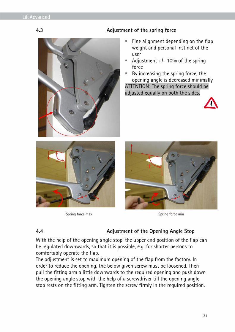
4.3 Adjustment of the spring force
Fine alignment depending on the flap weight and personal instinct of the user
Adjustment +/- 10% of the spring force
By increasing the spring force, the opening angle is decreased minimally
ATTENTION: The spring force should be adjusted equally on both the sides.
Spring force max Spring force min
4.4 Adjustment of the Opening Angle Stop
With the help of the opening angle stop, the upper end position of the flap can be regulated downwards, so that it is possible, e.g. for shorter persons to comfortably operate the flap. The adjustment is set to maximum opening of the flap from the factory. In order to reduce the opening, the below given screw must be loosened. Then pull the fitting arm a little downwards to the required opening and push down the opening angle stop with the help of a screwdriver till the opening angle stop rests on the fitting arm. Tighten the screw firmly in the required position.

Lift Advanced
32
ATTENTION: The screw must be firmly tightened; otherwise the opening angle stop moves again into the original position due to the pressure of the fitting arm.
Maximum opening angle Minimum opening angle
ATTENTION: Due to the shape of the fitting arm for Lift Advanced HS, it can happen that the arm touches the front edge of the cabinet top panel. In this case, the opening has to be reduced. TIP: It is advisable to reduce the opening for Lift Advanced HK. The beginning of the closing action is more comfortable as less force must be applied.
Background: In comparison to other opening types, the comparatively stronger spring is used for the same flap size and weight for HK because the lever which is formed by the flap is the biggest; the spring force must be overcome by the user while closing and it is the highest at the start of the closing action.

Lift Advanced
33
5 Description of Defects and their Correction
5.1 All Variants
Distortion of the fitting base plate
Details Cause Correction Prevention
1. Distortion of fitting base plate Happens possibly due to usage of very strong gas pressure springs. Does not affect the function of the fitting and is not visible after the installation of the cover cap, hence is not a defect or a reason for complaint.
- -

Lift Advanced
34
5.2 Lift Advanced HF
Top flap closes properly, bottom flap tilts frontward
Details Cause Rectification Prevention
1. while installation Overlay adjustment on the hinge has been done after the tightening of the joint screw
Remove the bottom flap, loosen the joint screw, do the adjustment at the hinge as required. Tighten the joint screw. Fit the bottom flap again. (see also page 12)
While fitting, after the fastening of the joint screws, do not carry out any adjustments at the hinge.
2. after some time of use Tilt adjustment screw on the front fitting is worn-out and can no longer hold the flap straight. (see photo) This is a result of overstretching of bottom front fitting during the usage on very huge cabinet heights. (see also page 15)
If the defect has happened recently and the wearing out of the screw has not progressed too far, then the transparent spacers can be introduced in the central joint. This will prevent a further overstretching of the front fitting.
Fitting of the spacer in situations as described in page 21 (J<65mm)

Lift Advanced
35
If no permanent solution can be attained by the usage of spacers, the fitting has to be exchanged. ATTENTION: while installing a new fitting, spacer has to be fitted
3. for aluminium frames Aluminium frame is not fixed with flush mounted screws. If the screws lie in the range of the fitting arms, the screw head prevents the flat attachment of the flap on the fitting arm.
Connecting screws of the frame have to be fitted flush.
Connecting screws of the frame have to be fitted flush.

Lift Advanced
36
Fitting arms are bent outwards, arms eventually grinding in the cabinet
Details Cause Rectification Prevention
During fitting, the joint screw has not been used or not been fixed firmly. Hence the upper metal arm moves against the lower plastic arm and this leads to abrasion and wearing out. After some time there is so much play in the joint that the metal arm tilts and the plastic arm pushes outward. In case of continued wear, the fitting arm grinds against the cabinet
The wear and tear cannot be undone. The fitting must be replaced. ATTENTION: Fitting instruction has to followed correctly!
Pay attention to the fitting sequence and carry out all the fitting steps carefully.

Lift Advanced
37
Flap does not close correctly
Details Cause Rectification Prevention
1. while assembling Dowel on the flap not inserted flush (see photo)
Disassemble the fitting, flush fit the dowel and re-fit
Dowels must be fitted flush in the flap.
Closing damper too strong Reduce closing damper action (see page 30)
-
Top flap wrongly mounted, fitting sequence not followed.
Disassemble both the flaps, loosen the joint screws and carry out the installation as per specification.
Follow the fitting sequence!
2. after some time of use Wear and tear in the joint (see page 38 “Fitting arms are bent outwards”)
see page 40 “Fitting arms are bent outwards”
see page 40 “Fitting arms are bent outwards”

Lift Advanced
38
Flaps close very loudly
Details Cause Rectification Prevention
In the fitting arm, there is a spring steel which pulls the flap close (like a cup hinge). The spring steel pulls the flap very strongly over the last centimetres, this might make a noise at the time of closing. This is NOT a defect, but a feature of the fitting.
Use Sensys hinges or Intermat hinges with additional damper.
-

Lift Advanced
39
5.3 Lift Advanced HK
Flap is tilted in front of the cabinet / Flap does not close properly
Details Cause Rectification Prevention
1. while fitting, the flap sticks out on the top
Depth adjustment of the hinge Adjust the depth adjustment of the hinge
-
2. while fitting, the flap sticks out at the bottom
Dowel on the flap not inserted flush (see photo)
Disassemble the fitting, flush fit the dowel and re-fit
Dowels must be fitted flush in the flap.
Tension in the fitting Open the flap, loosen the front mounting screws on the flap and push the front mounting in the elongated holes. (see photo)
While assembling, place the front mounting screws in the centre of the elongated holes. This setting should be suitable for when drilling of the hinges / mounting plates and the fitting have been carried out exactly.
Closing damper too strong Reduce closing damper action (see page 30)
-

Lift Advanced
40
Fitting arms bend outwards
Details Cause Rectification Prevention

Lift Advanced
41
5.4 Lift Advanced HS / HL
Fitting arms grind against the cabinet
Details Cause Rectification Prevention
While assembling Front adapter has twisted itself, top part (blue coloured in photo) lies sideways on the base plate (orange coloured) (Can happen while fastening the fixing screws)
Loosen the screws between the parts, align the parts (see photo) and tighten the screws again, while ensuring the alignment of the parts by hand
Check the alignment of the parts during fitting.

Lift Advanced
42
Flaps stays tilted in front of the cabinet / Flap does not close correctly
Details Cause Rectification Prevention
1. while assembling Dowel on the flap not inserted flush (see photo)
Disassemble the fitting, flush fit the dowel and re-fit
Dowels must be fitted flush in the flap.
2. while fitting, the flap sticks out on the top
Tilt adjustment on the front adapter loosely or wrongly installed
Carry out tilt adjustment and fasten the fixing screws
-
3. while fitting, the flap sticks out at the bottom or parallel in front of the cabinet
Tilt adjustment on the front adapter loosely or wrongly installed
Carry out tilt adjustment and fasten the fixing screws
-
Closing damper too strong Reduce the closing damper action (see page 30)
-

Lift Advanced
43
Fitting arm collides with the cabinet top panel when open (only HS)
Details Cause Rectification Prevention
Depending on the spring force , the settings of the spring force and the opening angle stop, it can happen that the fitting arm touches the top panel in the end position.
Reduce the opening, if necessary, increase the spring force setting
_

Lift Advanced
44
6 Others
6.1 Location of the contact points of the gas pressure springs
The base plate of the fitting is identical for all the 4 opening versions. However the placement of the upper ball pins for the types Lift Advanced HF and HK is different from Lift Advanced HL and HS (see photo). A few times in the past, it has happened that the ball pins were wrongly installed at the factory. Meanwhile, the cause for the mistake in fitting was eliminated. The wrong placement of the upper ball pin has an effect on the opening angle of the flap. If a customer complains regarding an extremely small opening angle, the position of the upper ball pin has to be checked.

Lift Advanced
45
6.2 Identification of the Fittings when fitted
In the versions Lift Advanced HF and Lift Advanced HL, there are variants which are suitable for different cabinet heights. Following representation should enable the user to exactly identify the fitting and check if the correct fitting has been installed.
Lift Advanced HF
Lift Advanced
HF
Lift Advanced
HL X
9079605 9079595 155mm 9079607 9079597 190mm 9079610 9079598 220mm 9079614 9079599 250mm 9079615 9079600 280mm
Lift Advanced HL