technical description final draft (alkindi engl...
TRANSCRIPT
0
June 16, 2014
Abdullah Alkindi
TWO-‐STROKE ENGINE CYCLE

The purpose of this document is to demonstrate the function of the two-‐stroke engine. The document starts with an introduction that gives a brief description of the two-‐ stroke engine and compares it with the four-‐stroke engine. Then, the document will discuss the main components of the two-‐stroke engine in details. This will be followed by one power stroke cycle description, where readers will understand how the parts work together as a single unit.
This document is intended for vocational-‐ technical school students, especially for those who focus on automobile repair and mechanics. Students should understand the process of the two-‐stroke engine function prior to getting their hands on one to work on it.
We ride vehicles every day and cannot imagine life and transportation without them, but we rarely think about how they work. Vehicles and many other applications use different types of combustion engines in order to work. In general, a combustion engine’s task is to convert the fuel’s chemical energy into mechanical power. There are many types of combustion engines and the most common types are the two-‐stroke and four-‐stroke engines; Table 1 in the next page shows the major differences between the two engines. A two-‐stroke engine is a combustion engine that delivers power in only one crankshaft revolution. The two-‐stroke engine consists of many different components that are either attached to each other or work to achieve a common task. The main components of a two-‐stroke engine are: cylinder, piston, sparkplug, crankshaft, intake port, exhaust port and transport port.
Why is it called a two-‐stroke engine? The name comes from the fact that it takes two strokes (piston’s movement up and down) to complete one cycle and deliver power.
Some applications and devices that use a two-‐stroke engine:
• Cars • Motorcycle • Chain saws • Jet skis • Model airplanes • Snowmobiles • Karts • Dirt bikes • Lawnmowers

In order to fully understand the cycle and the description of the entire engine, each component will be defined and explained separately. Figure 1 shows the major components of a two-‐stroke engine.
• Cylinder:
The cylinder, as shown in Figure 2, is an aluminum or iron casting that contains the inlets, outlets, piston, spark plugs and crankshaft. You can think of it as the chamber where the entire cycle takes place. The dimension of the cylinder is what people mostly hear about the car’s engine. For example, if a vehicle has a 3.0 L engine and 6 cylinders, it means that each cylinder has a volume of 0.5 L. This volume refers to the piston’s area multiplied by the distance traveled by the piston (stroke).
Two-‐Stroke Four-‐Stroke
Power delivered in one crankshaft revolution
Power delivered in two crankshaft revolutions
Fuel not fully consumed due to combining tasks in one stroke Fuel is fully consumed
Able to operate clockwise and counterclockwise
Can operate in one direction only
Weight of engine per horsepower is low Weight of engine per horsepower is
comparatively high Thermal efficiency is low Thermal efficiency is comparatively high
!!!
Spark Plug !
Cylinder ! Exhaust
Port !
Piston !
Transfer Port!
Intake Port !
Crankshaft
Figure 2. Cylinder (2)
Figure 1. Two-‐stroke engine components (1)
Table 1. Two-‐stroke engine vs. four-‐stroke engine

• Piston
A piston, shown in Figure 3, is an aluminum cylindrical part that moves up and down inside the cylinder depending on the pressure of the fuel-‐air mixture. The piston is connected to the crankshaft by a connecting rod. The main function of the piston is to convert the expansion of the ignited gases into upward and downward motion that rotates the crankshaft to generate power. The piston’s dimensions vary depending on the engine size and should exactly match the cylinder size to minimize any fuel escaping and loss of efficiency.
• Spark Plug
The spark plug is a device that uses current to fire the fuel-‐air mixture within the combustion chamber. Figure 4 shows a spark plug that is used in different kinds of engines.
• Combustion Chamber
A combustion chamber is the upper part of the cylinder where the fuel-‐air mixture gets burned.
• Crankshaft
A crankshaft, Shown in Figure 5, is a device that translates reciprocating linear piston motion into rotational motion, which is then used as a mechanical power.
Figure 3. Pistons (3)
Figure 4. Spark Plug (4)
Figure 5. Crankshaft attached by a connecting rod (5)
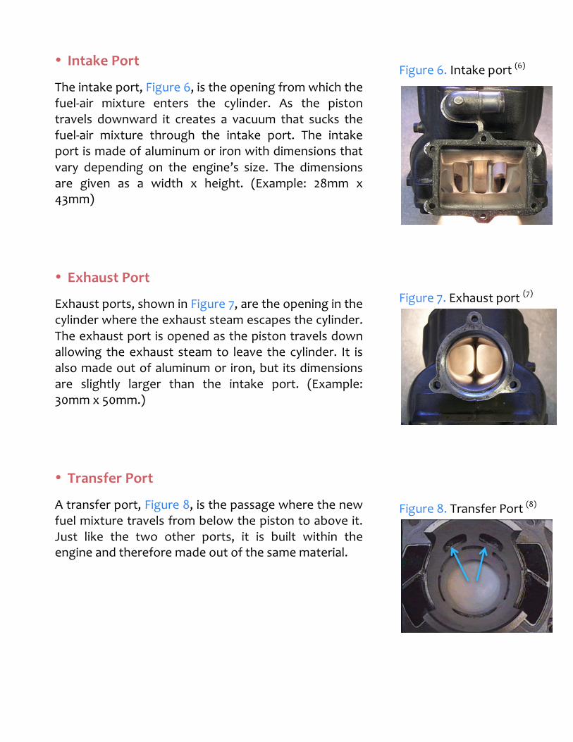
• Intake Port
The intake port, Figure 6, is the opening from which the fuel-‐air mixture enters the cylinder. As the piston travels downward it creates a vacuum that sucks the fuel-‐air mixture through the intake port. The intake port is made of aluminum or iron with dimensions that vary depending on the engine’s size. The dimensions are given as a width x height. (Example: 28mm x 43mm)
• Exhaust Port
Exhaust ports, shown in Figure 7, are the opening in the cylinder where the exhaust steam escapes the cylinder. The exhaust port is opened as the piston travels down allowing the exhaust steam to leave the cylinder. It is also made out of aluminum or iron, but its dimensions are slightly larger than the intake port. (Example: 30mm x 50mm.)
• Transfer Port
A transfer port, Figure 8, is the passage where the new fuel mixture travels from below the piston to above it. Just like the two other ports, it is built within the engine and therefore made out of the same material.
Figure 7. Exhaust port (7)
Figure 8. Transfer Port (8)
Figure 6. Intake port (6)

The two-‐stroke engine cycle is divided into two main phases, up stroke and down stroke. During each stroke, several events occur simultaneously as indicated in Figures 9-‐10.
Up Stroke -‐ Intake and Compression:
The first stroke is the upward movement of the piston, which performs two main duties, intake and compression. As the piston travels upward it covers both the exhaust and transfer port. This movement traps the fuel-‐air mixture, which enters the cylinder through the intake port. As the piston keeps moving, it begins compressing the fuel-‐air mixture; at the same time it uncovers the intake port, allowing the cylinder to suck in a new mixture. As this stroke reaches an end, the spark plug ignites, taking the cycle to the next stroke. The intake and compression stroke can be seen in Figure 9 below in steps 1 to 4.
!!!!!!
Transfer and exhausted ports
are covered.
Fuel is getting compressed as piston moves
upward
The spark plug ignites fuel-air
mixture.
Piston reaches its top position and more fuel enters the cylinder from the intake port
1! 2! 3! 4!
Figure 9. A diagram shows the main steps of the up stroke (9)

Down Stroke -‐ Power and Exhaust:
The second stroke, also known as the power and exhaust stroke, is the downward movement of the piston, where the power is delivered to the crankshaft and the exhaust steam leaves. After the fuel is ignited by the spark plug, the fuel-‐air mixture burns and increases both the temperature and pressure. Consequently, The pressure increase forces the piston to move down in the cylinder. As the piston travels down, it blocks the intake port and at the same time opens the exhaust port. Further movement of the piston opens the transfer port, which allows the new fuel-‐air mixture to travel upward. The new mixture flows above the piston forcing the exhaust steam out through the exhaust port. The power stroke is easily understood from steps 5-‐8 in Figure 10 below.
Figure 10. A diagram shows the main steps of the down stroke (10)
!Fuel-air mixture
combusts leading to a pressure increase
The piston is moving downward due to the
pressure increase
New fuel enters the combustion chamber and exhaust steam
exits
Intake port is covered as piston moves downward
5! 8!7!6!
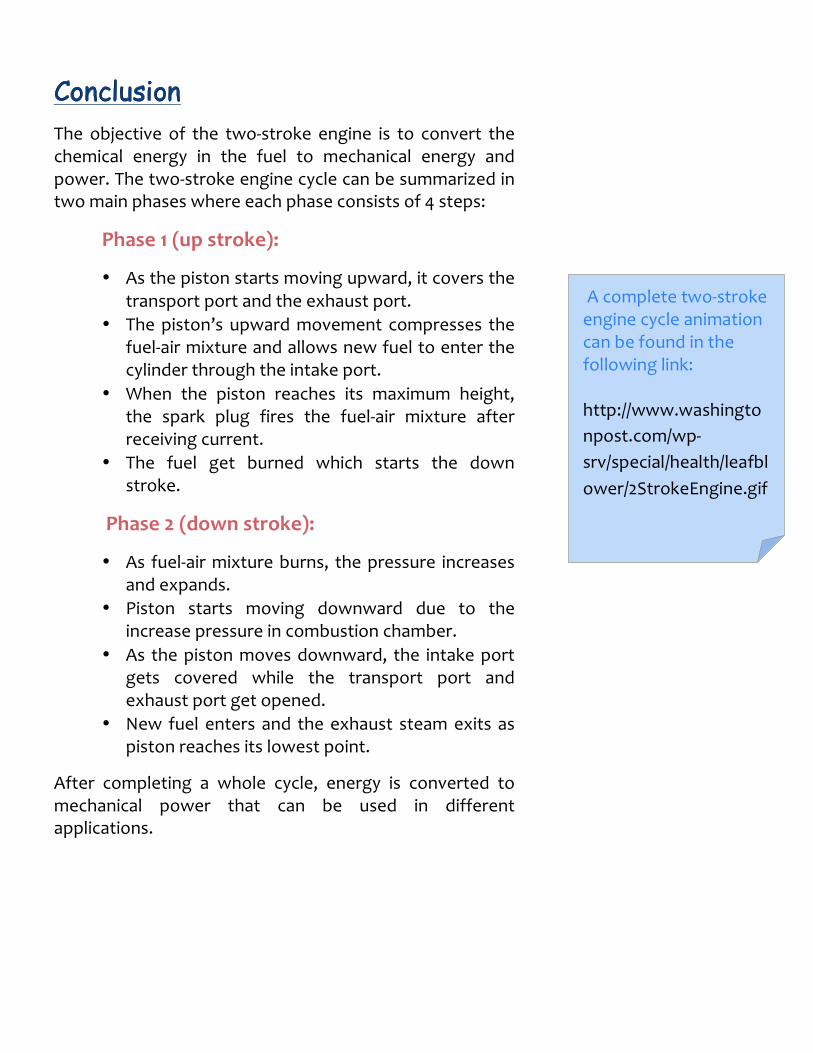
The objective of the two-‐stroke engine is to convert the chemical energy in the fuel to mechanical energy and power. The two-‐stroke engine cycle can be summarized in two main phases where each phase consists of 4 steps:
Phase 1 (up stroke):
• As the piston starts moving upward, it covers the transport port and the exhaust port.
• The piston’s upward movement compresses the fuel-‐air mixture and allows new fuel to enter the cylinder through the intake port.
• When the piston reaches its maximum height, the spark plug fires the fuel-‐air mixture after receiving current.
• The fuel get burned which starts the down stroke.
Phase 2 (down stroke):
• As fuel-‐air mixture burns, the pressure increases and expands.
• Piston starts moving downward due to the increase pressure in combustion chamber.
• As the piston moves downward, the intake port gets covered while the transport port and exhaust port get opened.
• New fuel enters and the exhaust steam exits as piston reaches its lowest point.
After completing a whole cycle, energy is converted to mechanical power that can be used in different applications.
A complete two-‐stroke engine cycle animation can be found in the following link: http://www.washingtonpost.com/wp-‐srv/special/health/leafblower/2StrokeEngine.gif

THEORY OF 2-‐STROKE OUTBOARD MOTOR OPERATION -‐-‐ Mastertech Marine. (2012, March 1). Retrieved June 15, 2014, from http://www.maxrules.com/fixtheory2.html
2 stroke and 4 stroke engines. (n.d.). Retrieved June 12,
2014, from http://www.deepscience.com/articles/engines.html
Animated Engines. (n.d.). -‐ Two stroke. Retrieved June 14,
2014, from http://www.animatedengines.com/twostroke.html
(Cover page figure) 2 stroke engines. (n.d.). 2 stroke engines. Retrieved June
12, 2014, from http://www.barnardmicrosystems.com/UAV/engines/2_stroke.html
(1, 9, 10) (Cropped, text and arrows added) Patterson, C. (2013, September 17). The two-‐stroke engine.
Washington Post. Retrieved June 15, 2014, from http://www.washingtonpost.com/wp-‐srv/special/health/leafblower/index.html
(2) MADMAN ENGINEERING. (n.d.). Cylinder Porting,
Engine Porting, Dirt Bike Porting, 2-‐Stroke Porting, 4-‐Stroke Porting, Cylinder Head Porting. Retrieved June 15, 2014, from http://www.madmanengineering.com/porting.htm
(3) Custom Pistons: Increase The Power of Your Ride. (n.d.). Retrieved June 16, 2014, from http://www.howrah.org/piston.html
(4) (n.d.). . Retrieved June 16, 2014, from http://www.truckmodcentral.com/forums/f57/what-‐engine-‐does-‐spark-‐plug-‐fit-‐27608/
(5) (n.d.). . Retrieved June 16, 2014, from http://www.scootershack.co.uk/threads/2-‐stroke-‐mechanical-‐word-‐glossary-‐by-‐j-‐nitro.2506/
(6, 7)Rich's-‐Taylor'd-‐Porting-‐modern-‐2-‐Stroke-‐engine-‐porting. (n.d.). Retrieved June 16, 2014, from http://richstaylordporting.com/modern_2-‐strokePorting.html
(8) (Arrows added) MacDizzy's 1989 Blaster Engine Rebuild -‐ Part 2, Two-‐Stroke Software Review. (2012, November 29). Retrieved June 16, 2014, from http://www.macdizzy.com/1989ahopup.htm