technical data - link-belt cranes 5747 (supersedes 5724)-0915-s3 link‐belt cranes atc‐3210...
TRANSCRIPT
15747 (supersedes 5724)-0915-S3
ATC‐3210Link‐Belt Cranes
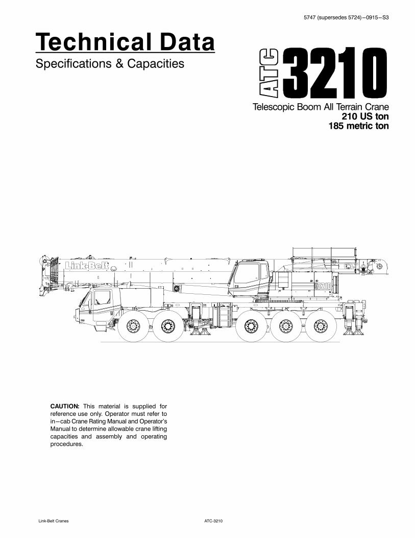
Technical DataSpecifications & Capacities
Telescopic Boom All Terrain Crane210 US ton
185 metric ton
CAUTION: This material is supplied for
reference use only. Operator must refer to
in-cab Crane Rating Manual and Operator's
Manual to determine allowable crane lifting
capacities and assembly and operating
procedures.

5747 (supersedes 5724)-0915-S3
ATC‐3210 Link‐Belt Cranes

5747 (supersedes 5724)-0915-S3
ATC‐3210Link‐Belt Cranes
Table Of Contents
Boom, Attachments, and Upper Structure 1. . . . . . . . . . . . . . . . . . . . . . . . . . . . . . . . . . . . . . . . . . . . . . . . . . . .
Boom 1. . . . . . . . . . . . . . . . . . . . . . . . . . . . . . . . . . . . . . . . . . . . . . . . . . . . . . . . . . . . . . . . . . . . . . . . . . . . . . . . . . . .
Boom Wear Pads 1. . . . . . . . . . . . . . . . . . . . . . . . . . . . . . . . . . . . . . . . . . . . . . . . . . . . . . . . . . . . . . . . . . . . . . . . .
Boom Head 1. . . . . . . . . . . . . . . . . . . . . . . . . . . . . . . . . . . . . . . . . . . . . . . . . . . . . . . . . . . . . . . . . . . . . . . . . . . . .
Boom Elevation 1. . . . . . . . . . . . . . . . . . . . . . . . . . . . . . . . . . . . . . . . . . . . . . . . . . . . . . . . . . . . . . . . . . . . . . . . . .
Auxiliary Lifting Sheave - Optional 1. . . . . . . . . . . . . . . . . . . . . . . . . . . . . . . . . . . . . . . . . . . . . . . . . . . . . . . . .
Heavy Duty Lifting Pendants Package - Optional 1. . . . . . . . . . . . . . . . . . . . . . . . . . . . . . . . . . . . . . . . . . . .
Hook Blocks and Balls - Optional 1. . . . . . . . . . . . . . . . . . . . . . . . . . . . . . . . . . . . . . . . . . . . . . . . . . . . . . . . . .
Fly - Optional 1. . . . . . . . . . . . . . . . . . . . . . . . . . . . . . . . . . . . . . . . . . . . . . . . . . . . . . . . . . . . . . . . . . . . . . . . . . .
Fly Extensions - Optional 1. . . . . . . . . . . . . . . . . . . . . . . . . . . . . . . . . . . . . . . . . . . . . . . . . . . . . . . . . . . . . . . . .
Upper Operator's Cab and Controls 2. . . . . . . . . . . . . . . . . . . . . . . . . . . . . . . . . . . . . . . . . . . . . . . . . . . . . . . . . .
Swing 3. . . . . . . . . . . . . . . . . . . . . . . . . . . . . . . . . . . . . . . . . . . . . . . . . . . . . . . . . . . . . . . . . . . . . . . . . . . . . . . . . . . .
Central Lubrication System 3. . . . . . . . . . . . . . . . . . . . . . . . . . . . . . . . . . . . . . . . . . . . . . . . . . . . . . . . . . . . . . . . .
Electrical 3. . . . . . . . . . . . . . . . . . . . . . . . . . . . . . . . . . . . . . . . . . . . . . . . . . . . . . . . . . . . . . . . . . . . . . . . . . . . . . . . .
Hydraulic System 3. . . . . . . . . . . . . . . . . . . . . . . . . . . . . . . . . . . . . . . . . . . . . . . . . . . . . . . . . . . . . . . . . . . . . . . . . .
Pump Drive 4. . . . . . . . . . . . . . . . . . . . . . . . . . . . . . . . . . . . . . . . . . . . . . . . . . . . . . . . . . . . . . . . . . . . . . . . . . . . . . .
Fuel Tank 4. . . . . . . . . . . . . . . . . . . . . . . . . . . . . . . . . . . . . . . . . . . . . . . . . . . . . . . . . . . . . . . . . . . . . . . . . . . . . . . . .
Engine 4. . . . . . . . . . . . . . . . . . . . . . . . . . . . . . . . . . . . . . . . . . . . . . . . . . . . . . . . . . . . . . . . . . . . . . . . . . . . . . . . . . .
Load Hoist System 5. . . . . . . . . . . . . . . . . . . . . . . . . . . . . . . . . . . . . . . . . . . . . . . . . . . . . . . . . . . . . . . . . . . . . . . . .
Load Hoist Performance 5. . . . . . . . . . . . . . . . . . . . . . . . . . . . . . . . . . . . . . . . . . . . . . . . . . . . . . . . . . . . . . . . . . .
2M Main (Front) and Optional Auxiliary (Rear) Winches 5. . . . . . . . . . . . . . . . . . . . . . . . . . . . . . . . . . . . . . .
Counterweight 5. . . . . . . . . . . . . . . . . . . . . . . . . . . . . . . . . . . . . . . . . . . . . . . . . . . . . . . . . . . . . . . . . . . . . . . . . . . .
Carrier 7. . . . . . . . . . . . . . . . . . . . . . . . . . . . . . . . . . . . . . . . . . . . . . . . . . . . . . . . . . . . . . . . . . . . . . . . . . . . . . . . . . . .
General 7. . . . . . . . . . . . . . . . . . . . . . . . . . . . . . . . . . . . . . . . . . . . . . . . . . . . . . . . . . . . . . . . . . . . . . . . . . . . . . . . . . .
Outriggers 7. . . . . . . . . . . . . . . . . . . . . . . . . . . . . . . . . . . . . . . . . . . . . . . . . . . . . . . . . . . . . . . . . . . . . . . . . . . . . . . .
Steering and Axles 7. . . . . . . . . . . . . . . . . . . . . . . . . . . . . . . . . . . . . . . . . . . . . . . . . . . . . . . . . . . . . . . . . . . . . . . . .
Suspension 7. . . . . . . . . . . . . . . . . . . . . . . . . . . . . . . . . . . . . . . . . . . . . . . . . . . . . . . . . . . . . . . . . . . . . . . . . . . . . . .
Ground Control Outrigger/Suspension Controls 7. . . . . . . . . . . . . . . . . . . . . . . . . . . . . . . . . . . . . . . . . . . . . . .
Tires and Wheels 8. . . . . . . . . . . . . . . . . . . . . . . . . . . . . . . . . . . . . . . . . . . . . . . . . . . . . . . . . . . . . . . . . . . . . . . . . .
Brakes 8. . . . . . . . . . . . . . . . . . . . . . . . . . . . . . . . . . . . . . . . . . . . . . . . . . . . . . . . . . . . . . . . . . . . . . . . . . . . . . . . . . .
Central Lubrication System 8. . . . . . . . . . . . . . . . . . . . . . . . . . . . . . . . . . . . . . . . . . . . . . . . . . . . . . . . . . . . . . . . .
Electrical 8. . . . . . . . . . . . . . . . . . . . . . . . . . . . . . . . . . . . . . . . . . . . . . . . . . . . . . . . . . . . . . . . . . . . . . . . . . . . . . . . .
Transmission 8. . . . . . . . . . . . . . . . . . . . . . . . . . . . . . . . . . . . . . . . . . . . . . . . . . . . . . . . . . . . . . . . . . . . . . . . . . . . . .
Fuel Tank 8. . . . . . . . . . . . . . . . . . . . . . . . . . . . . . . . . . . . . . . . . . . . . . . . . . . . . . . . . . . . . . . . . . . . . . . . . . . . . . . . .
Engine 8. . . . . . . . . . . . . . . . . . . . . . . . . . . . . . . . . . . . . . . . . . . . . . . . . . . . . . . . . . . . . . . . . . . . . . . . . . . . . . . . . . .
Hydraulic System 8. . . . . . . . . . . . . . . . . . . . . . . . . . . . . . . . . . . . . . . . . . . . . . . . . . . . . . . . . . . . . . . . . . . . . . . . . .
Pump Drive 8. . . . . . . . . . . . . . . . . . . . . . . . . . . . . . . . . . . . . . . . . . . . . . . . . . . . . . . . . . . . . . . . . . . . . . . . . . . . . . .
Carrier Speeds and Gradeability 9. . . . . . . . . . . . . . . . . . . . . . . . . . . . . . . . . . . . . . . . . . . . . . . . . . . . . . . . . . . . .
Lower Cab and Controls 10. . . . . . . . . . . . . . . . . . . . . . . . . . . . . . . . . . . . . . . . . . . . . . . . . . . . . . . . . . . . . . . . . . . .
Additional Equipment 11. . . . . . . . . . . . . . . . . . . . . . . . . . . . . . . . . . . . . . . . . . . . . . . . . . . . . . . . . . . . . . . . . . . . . .
Axle Loads - English 12. . . . . . . . . . . . . . . . . . . . . . . . . . . . . . . . . . . . . . . . . . . . . . . . . . . . . . . . . . . . . . . . . . . . . . .
Axle Loads - Metric 13. . . . . . . . . . . . . . . . . . . . . . . . . . . . . . . . . . . . . . . . . . . . . . . . . . . . . . . . . . . . . . . . . . . . . . . .
Axle Loads with 2-Axle or 3-Axle Boom Dolly (3rd Axle Down) - English 14. . . . . . . . . . . . . . . . . . . . .
Axle Loads with 2-Axle or 3-Axle Boom Dolly (3rd Axle Down) - Metric 15. . . . . . . . . . . . . . . . . . . . . .
General Dimensions 16. . . . . . . . . . . . . . . . . . . . . . . . . . . . . . . . . . . . . . . . . . . . . . . . . . . . . . . . . . . . . . . . . . . . . . . .
Working Range Diagram - Main Boom 17. . . . . . . . . . . . . . . . . . . . . . . . . . . . . . . . . . . . . . . . . . . . . . . . . . . . . .

5747 (supersedes 5724)-0915-S3
ATC-3210 Link-Belt Cranes
Working Range Diagram - Main Boom + Fly 18. . . . . . . . . . . . . . . . . . . . . . . . . . . . . . . . . . . . . . . . . . . . . . . .
Boom Extend Modes 19. . . . . . . . . . . . . . . . . . . . . . . . . . . . . . . . . . . . . . . . . . . . . . . . . . . . . . . . . . . . . . . . . . . . . . .
Main Boom Lift Capacity Charts - Standard 20. . . . . . . . . . . . . . . . . . . . . . . . . . . . . . . . . . . . . . . . . . . . . . . . .
0 lb Counterweight Fully Extended Outriggers 360° Rotation 20. . . . . . . . . . . . . . . . . . . . . . . . . . . . . . . . . .
36,000 lb Counterweight Fully Extended Outriggers 360° Rotation 21. . . . . . . . . . . . . . . . . . . . . . . . . . . . .
Main Boom Lift Capacity Charts - Optional 22. . . . . . . . . . . . . . . . . . . . . . . . . . . . . . . . . . . . . . . . . . . . . . . . . .
58,000 lb Counterweight Fully Extended Outriggers 360° Rotation 22. . . . . . . . . . . . . . . . . . . . . . . . . . . . .
80,000 lb Counterweight Fully Extended Outriggers 360° Rotation 23. . . . . . . . . . . . . . . . . . . . . . . . . . . . .
102,000 lb Counterweight Fully Extended Outriggers 360° Rotation 24. . . . . . . . . . . . . . . . . . . . . . . . . . . .
115,500 lb Counterweight Fully Extended Outriggers 360° Rotation 25. . . . . . . . . . . . . . . . . . . . . . . . . . . .
Manual & Hydraulic Offset Fly Attachment Lift Capacity Charts - Optional 26. . . . . . . . . . . . . . . . . . . . .
36,000 lb Counterweight Fully Extended Outriggers 360° Rotation 26. . . . . . . . . . . . . . . . . . . . . . . . . . . . .
Main Boom + 12 ft Offset Fly (Manual Offsets 2°, 15°, 30°, 45° & Hydraulic Offsets 2° 45°) 26. . . . . .
115,500 lb Counterweight Fully Extended Outriggers 360° Rotation 27. . . . . . . . . . . . . . . . . . . . . . . . . . . .
Main Boom + 12 ft Offset Fly (Manual Offsets 2°, 15°, 30°, 45° & Hydraulic Offsets 2° 45°) 27. . . . . .
Manual Offset Fly Attachment Lift Capacity Charts - Optional 28. . . . . . . . . . . . . . . . . . . . . . . . . . . . . . . . .
36,000 lb Counterweight Fully Extended Outriggers 360° Rotation 28. . . . . . . . . . . . . . . . . . . . . . . . . . . . .
200.1 ft Main Boom Length + 40 ft & 67 ft Manual Offset Fly (2°, 15°, 30°, 45° Offsets) 28. . . . . . . . . . .
115,500 lb Counterweight Fully Extended Outriggers 360° Rotation 29. . . . . . . . . . . . . . . . . . . . . . . . . . . .
200.1 ft Main Boom Length + 40 ft & 67 ft Manual Offset Fly (2°, 15°, 30°, 45° Offsets) 29. . . . . . . . . . .
200.1 ft Main Boom Length + 92 ft & 117 ft Manual Offset Fly (2°, 15°, 30°, 45° Offsets) 30. . . . . . . . . .
Hydraulic Offset Fly Attachment Lift Capacity Charts - Optional 31. . . . . . . . . . . . . . . . . . . . . . . . . . . . . . .
36,000 lb Counterweight Fully Extended Outriggers 360° Rotation 31. . . . . . . . . . . . . . . . . . . . . . . . . . . . .
200.1 ft Main Boom Length + 40 ft & 67 ft Hydraulic Offset Fly (2° 45° Offsets) 31. . . . . . . . . . . . . . . . .
115,500 lb Counterweight Fully Extended Outriggers 360° Rotation 32. . . . . . . . . . . . . . . . . . . . . . . . . . . .
200.1 ft Main Boom Length + 40 ft & 67 ft Hydraulic Offset Fly (2° 45° Offsets) 32. . . . . . . . . . . . . . . . .
Main Boom Lift Capacity Charts - Metric 33. . . . . . . . . . . . . . . . . . . . . . . . . . . . . . . . . . . . . . . . . . . . . . . . . . . .
16.3t Counterweight Fully Extended Outriggers 360° Rotation 33. . . . . . . . . . . . . . . . . . . . . . . . . . . . . . . .
Main Boom Lift Capacity Charts - Optional - Metric 34. . . . . . . . . . . . . . . . . . . . . . . . . . . . . . . . . . . . . . . . .
52.4t Counterweight Fully Extended Outriggers 360° Rotation 34. . . . . . . . . . . . . . . . . . . . . . . . . . . . . . . .
Manual & Hydraulic Offset Fly Attachment Lift Capacity Charts - Optional - Metric 35. . . . . . . . . . . .
16.3t Counterweight Fully Extended Outriggers 360° Rotation 35. . . . . . . . . . . . . . . . . . . . . . . . . . . . . . . .
Main Boom + 3.7m Offset Fly (Manual Offsets 2°, 15°, 30°, 45° & Hydraulic Offsets 2° 45°) 35. . . . .
52.4t Counterweight Fully Extended Outriggers 360° Rotation 36. . . . . . . . . . . . . . . . . . . . . . . . . . . . . . . .
Main Boom + 3.7m Offset Fly (Manual Offsets 2°, 15°, 30°, 45° & Hydraulic Offsets 2° 45°) 36. . . . .
Manual Offset Fly Attachment Lift Capacity Charts - Optional - Metric 37. . . . . . . . . . . . . . . . . . . . . . . .
16.3t Counterweight Fully Extended Outriggers 360° Rotation 37. . . . . . . . . . . . . . . . . . . . . . . . . . . . . . . .
61m Main Boom Length + 12.2m & 20.4m Manual Offset Fly (2°, 15°, 30°, 45° Offsets) 37. . . . . . . . . .
52.4t Counterweight Fully Extended Outriggers 360° Rotation 38. . . . . . . . . . . . . . . . . . . . . . . . . . . . . . . .
61m Main Boom Length + 12.2m & 20.4m Manual Offset Fly (2°, 15°, 30°, 45° Offsets) 38. . . . . . . . . .
61m Main Boom Length + 28m & 35.6m Manual Offset Fly (2°, 15°, 30°, 45° Offsets) 39. . . . . . . . . . . .
Hydraulic Offset Fly Attachment Lift Capacity Charts - Optional - Metric 40. . . . . . . . . . . . . . . . . . . . . .
16.3t Counterweight Fully Extended Outriggers 360° Rotation 40. . . . . . . . . . . . . . . . . . . . . . . . . . . . . . . .
61m Main Boom Length + 12.2m & 20.4m Hydraulic Offset Fly (2° 45° Offsets) 40. . . . . . . . . . . . . . . .
52.4t Counterweight Fully Extended Outriggers 360° Rotation 41. . . . . . . . . . . . . . . . . . . . . . . . . . . . . . . .
61m Main Boom Length + 12.2m & 20.4m Hydraulic Offset Fly (2° 45° Offsets) 41. . . . . . . . . . . . . . . .
61m Main Boom Length + 28m & 35.7m Hydraulic Offset Fly (2° 45° Offsets) 42. . . . . . . . . . . . . . . . . .
15747 (supersedes 5724)-0915-S3
ATC‐3210Link‐Belt Cranes
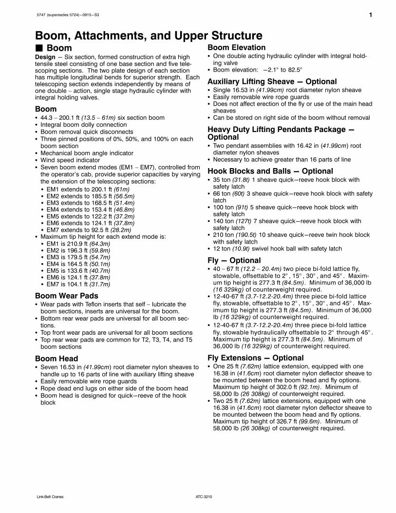
Boom, Attachments, and Upper Structure� BoomDesign - Six section, formed construction of extra hightensile steel consisting of one base section and five telescoping sections. The two plate design of each sectionhas multiple longitudinal bends for superior strength. Eachtelescoping section extends independently by means ofone double – action, single stage hydraulic cylinder withintegral holding valves.
Boom� 44.3 – 200.1 ft (13.5 – 61m) six section boom� Integral boom dolly connection� Boom removal quick disconnects� Three pinned positions of 0%, 50%, and 100% on each
boom section� Mechanical boom angle indicator� Wind speed indicator� Seven boom extend modes (EM1 – EM7), controlled from
the operator’s cab, provide superior capacities by varyingthe extension of the telescoping sections:
� EM1 extends to 200.1 ft (61m)� EM2 extends to 185.5 ft (56.5m)� EM3 extends to 168.5 ft (51.4m)� EM4 extends to 153.4 ft (46.8m)� EM5 extends to 122.2 ft (37.2m)� EM6 extends to 124.1 ft (37.8m)� EM7 extends to 92.5 ft (28.2m)
� Maximum tip height for each extend mode is:� EM1 is 210.9 ft (64.3m)� EM2 is 196.3 ft (59.8m)� EM3 is 179.5 ft (54.7m)� EM4 is 164.5 ft (50.1m)� EM5 is 133.6 ft (40.7m)� EM6 is 124.1 ft (37.8m)� EM7 is 104.1 ft (31.7m)
Boom Wear Pads� Wear pads with Teflon inserts that self – lubricate the
boom sections, inserts are universal for the boom.� Bottom rear wear pads are universal for all boom sec
tions.� Top front wear pads are universal for all boom sections� Top rear wear pads are common for T2, T3, T4, and T5
boom sections
Boom Head� Seven 16.53 in (41.99cm) root diameter nylon sheaves to
handle up to 16 parts of line with auxiliary lifting sheave� Easily removable wire rope guards� Rope dead end lugs on either side of the boom head� Boom head is designed for quick-reeve of the hook
block
Boom Elevation� One double acting hydraulic cylinder with integral hold
ing valve� Boom elevation: -2.1° to 82.5°
Auxiliary Lifting Sheave - Optional� Single 16.53 in (41.99cm) root diameter nylon sheave� Easily removable wire rope guards� Does not affect erection of the fly or use of the main head
sheaves� Can be stored on right side of the boom without removal
Heavy Duty Lifting Pendants Package -Optional� Two pendant assemblies with 16.42 in (41.99cm) root
diameter nylon sheaves� Necessary to achieve greater than 16 parts of line
Hook Blocks and Balls - Optional� 35 ton (31.8t) 1 sheave quick-reeve hook block with
safety latch� 66 ton (60t) 3 sheave quick-reeve hook block with safety
latch� 100 ton (91t) 5 sheave quick-reeve hook block with
safety latch� 140 ton (127t) 7 sheave quick-reeve hook block with
safety latch� 210 ton (190.5t) 10 sheave quick-reeve twin hook block
with safety latch� 12 ton (10.9t) swivel hook ball with safety latch
Fly - Optional� 40 – 67 ft (12.2 – 20.4m) two piece bifold lattice fly,
stowable, offsettable to 2° , 15° , 30° , and 45° . Maximum tip height is 277.3 ft (84.5m). Minimum of 36,000 lb(16 329kg) of counterweight required.
� 124067 ft (3.712.220.4m) three piece bifold latticefly, stowable, offsettable to 2° , 15° , 30° , and 45° . Maximum tip height is 277.3 ft (84.5m). Minimum of 36,000lb (16 329kg) of counterweight required.
� 124067 ft (3.712.220.4m) three piece bifold latticefly, stowable hydraulically offsettable to 2° through 45° .Maximum tip height is 277.3 ft (84.5m). Minimum of36,000 lb (16 329kg) of counterweight required.
Fly Extensions - Optional� One 25 ft (7.62m) lattice extension, equipped with one
16.38 in (41.6cm) root diameter nylon deflector sheave tobe mounted between the boom head and fly options.Maximum tip height of 302.0 ft (92.1m). Minimum of58,000 lb (26 308kg) of counterweight required.
� Two 25 ft (7.62m) lattice extensions, equipped with one16.38 in (41.6cm) root diameter nylon deflector sheave tobe mounted between the boom head and fly options.Maximum tip height of 326.7 ft (99.6m). Minimum of58,000 lb (26 308kg) of counterweight required.

2 5747 (supersedes 5724)-0915-S3
ATC‐3210 Link‐Belt Cranes
� Upper Operator's Cab and ControlsEnvironmental Cab - Fully enclosed, one person cab ofgalvaneal steel structure with acoustical insulation.Equipped with:� Tilting cab up to 20°� Tinted and tempered glass windows� Five way adjustable, cushioned seat with headrests, and
seat belt� Extra-large fixed front window with windshield wiper and
washer� Swing up roof window with windshield wiper� Sliding left side door with large fixed window� Sliding right side window for ventilation� Engine dependent warm - water heater with air ducts for
front windshield defroster and cab floor� Defroster fan for the front window� Bubble level� Circulating fan� Sun screen� LED dome light� Cup holder� Fire extinguisher� Left side viewing mirror� Two position travel swing lock� AM/FM Radio
Air Conditioning - Integral with cab heating system utilizing the same ventilation outlets
Armrest Controls - Two dual axis electronic joystick controllers or optional single axis electronic controllers for:� Swing� Boom hoist� Main front winch� Auxiliary rear winch - optional� Drum rotation indication� Drum rotation indicator activation switch� Winch high/low speed disable switch(es)� Cab heater and A/C controls� Throttle lock switch� Throttle set/resume switch� Cab tilt switch� Counterweight handling switch� Warning horn button� Swing park brake
Foot Controls� Boom Telescope� Swing brake� Engine throttle
Right Front Console - Controls and indicators for:� Warning horn button� Function disable switch� Cab floodlights switch� Console dimmer switch� 2-12 volt accessory outlets (Switched & Unswitched)� Emergency engine shutdown� Windshield wiper/washer switch� Outrigger keypad
� Upper ignition switch� Lower ignition switch� Boom floodlights switch - optional� Rotating beacon/strobe light switch - optional� Hydraulic offset fly switch - optional
Camera Display - Located on dash console
� Displays right side of upper� Displays main and auxiliary winches
Cab Instrumentation - Ergonomically positioned LCD display, CANBUS instrumentation for crane operation including:� Tachometer� Change Hydraulic filter indication� Engine water temperature� Fuel level� Hydraulic oil temperature� Stop engine� Check engine� Wait to start� High exhaust temperature light(1)
� Exhaust system cleaning light(1)
� Exhaust system cleaning Disabled light(1)
� Swing park brake light� Fine metering function set & %� Diesel exhaust fluid (DEF) Low Light(1)
� Engine air filter high restriction Light� Engine Running Hours� Hydraulic Oil Life Indicator� Engine Oil Life Indicator� General Service Indicator� Carrier engine indicator lights and gauges� Engine oil pressure� Battery voltage� Engine hours� Fuel rate (gal/hr)� Engine load� Third wrap indicator activation & setup� Engine Diagnostics� Electronic Control Diagnostics� Outrigger level indicator� Exhaust system cleaning inhibit switch(1)
� Exhaust system cleaning initiate switch(1)
� Service interval indicator� Hydraulic oil� Engine oil� Miscellaneous - user defined
Diagnostic Center - Located on the left side of the frontpanel below the windshield� Engine diagnostic� RCL CANBUS diagnostic� Boom CANBUS diagnostic� Crane Controller USB diagnostic� RCL controller USB diagnostic� Manual boom control connection� Manual crane control connection
(1) (Tier 4f / Stage IV engine only)

35747 (supersedes 5724)-0915-S3
ATC‐3210Link‐Belt Cranes
LinkBelt Pulse – The LinkBelt inhouse designed, totalcrane operating system that utilizes the display as areadout and operator interface for the following systems:� Rated capacity limiter – LCD graphic audio – visual
warning system integrated into the dash with anti – twoblock and function limiter. Operating data includes:� Crane configuration� Boom length� Boom head height� Allowed load and % of allowed load� RCL light bar� Boom angle� Radius of load� Actual load� Wind speed� Highlighted unit of measurement on working screen� Active pin/latch status� Telescope operation displayed in real time� Counterweight installation/removal� Third wrap indicator� Diagnostics� Outrigger position sensing� Drum rotation direction indicator� Operator settable alarms (include):� Maximum and minimum boom angles� Maximum tip height� Maximum boom length� Swing left/right positions� Operator defined area (imaginary plane)
� Telematics – Cellular-based data logging andmonitoring system that provides:� Location and operational settings� Routine maintenance� Crane and engine monitoring� Diagnostic and fault codes
� Extend control module (ECM)� Controls the extend modes� Diagnostics
� Electronic controllers� Controls all load lifting functions� Diagnostics
� Fine metering� Controls the reaction speeds of the main and auxiliary
winches, boom hoist, and swing functions� Diagnostics
Integrated Third Wrap Indicator - Optional - Link‐BeltPulse color display visually and audibly warns the operatorwhen the wire rope is on the first/bottom layer and when
the wire rope is down to the last three wraps.
Integrated Third Wrap Function Kickout - Optional -Link-Belt Pulse color display visually and audibly warns
the operator when the wire rope is on the first/bottom layerand provides a function kickout when the wire rope is downto the last three wraps.
Internal RCL Light Bar - Visually informs the operatorwhen crane is approaching maximum load capacity with aseries of green, yellow, and red lights.
External RCL Light Bar - Optional - Visually informs theground crew when crane is approaching maximum loadcapacity with a series of green, yellow, and red lights.
� SwingMotor/Planetary - Two bidirectional hydraulic swing motors mounted to planetary reduction units for 360° continuous smooth swing at 1.5 rpm.
Swing Park Brake - 360°, electric over hydraulic, (springapplied/hydraulic released) multi-disc brake mountedbetween the speed reducer and the motor. Operated by aswitch in the operator’s cab.
Swing Brake - 360°, foot operated, hydraulic applied discbrake mounted to the reduction unit.
Swing Lock - Two – position swing lock (boom over the
front or rear) operated from the operator’s cab.
360° Positive Swing Lock - Optional - Meets New YorkCity requirement.
� Central Lubrication SystemAutomated lubrication unit that injects grease into the turntable bearing, boom hoist cylinder pins, boom foot pins,house lock (2-position), and cab tilt cylinder. Activated bya timer on the ignition switch.
� ElectricalTwo batteries provide 12 – volt operation and starting.
CANBUS wiring and components.
Swing Alarm - Audio/Visual warning device signals whenthe upper is swinging.
Lights� Two LED working lights on the front of the cab� Work Lighting Package - optional
Includes six (6) LED lights� Working light on top of the cab� Right side of superstructure facing forward� Left & right upper work platforms� Left & right sides of superstructure facing down
� One amber strobe beacon on top of the cab - optional� Boom floodlight - Single - optional� Boom floodlight - Dual - optional� Boom floodlight - High intensity remote controlled -
optional
Power Panel - Sealed power panel containing:� Battery disconnects� Hour meter� Fuses, circuit breakers, relays, diodes, resistors� Control modules

4 5747 (supersedes 5724)-0915-S3
ATC‐3210 Link‐Belt Cranes
� Hydraulic SystemMain Pumps� Two piston pumps for boom hoist and telescope� Two piston pumps for main and auxiliary winches� One piston pump for swing� One piston pump for counterweight removal and hydraul
ic fly option� One gear pump for engine fan� One gear pump for upper oil cooler fan� The upper engine powers the pumps. Combined pump
capacity of 218 gpm (825.2Lpm).
Hydraulic Reservoir - 148 gal (560.2L) capacity equippedwith sight level gauge. Diffusers built in for deaeration, andmagnetic drain plug.
Filtration� One, 7 – micron filter inside hydraulic reservoir, access
ible for easy replacement� One, 7 – micron charge filter next to the reservoir with an
in – cab indicator light� One suction strainer inside the hydraulic reservoir
Counterbalance Valves - Boom extend cylinder andboom hoist cylinder are equipped with counterbalancevalves to provide load lowering and prevents accidentalload drop when hydraulic power is suddenly reduced.
Hydraulic Oil Cooler - Mounted on right side above telescoping valve. Removes heat from the hydraulic oil.
Boom Hoist Float Valves - For transporting the boomover the rear of the crane with a boom dolly. Allows hydraulic oil within the boom hoist cylinder to flow betweenpiston side and case side.
Swing Brake Release Valve - For transporting the boomover the rear of the crane with a boom dolly. Holds the360° swing park brake in the released position allowingfree rotation of the upper structure.
� Pump DriveAll pumps are mechanically driven by the diesel engine.
� Fuel Tank� One 58 gal (219.5L) capacity aluminum diesel tank� One 5 gal (18.9L) capacity diesel exhaust fluid (DEF)
plastic tank
� Engine
Specification Cummins QSB-6.7
Emissions Compliance Level:
Tier 4f/Stage IV(1) Tier 3/Stage IIIA(2)
Maximum allowablesulfur content of fuel(PPM):
15 5,000
Numbers of cylinders 6 6
Cycle 4 4
Bore and Stroke:inch (mm)
4.21 x 4.88 (106.9 x124)
4.21 x 4.88 (106.9 x124)
Piston Displacement:in3 (cm3)
408 (6 702) 408 (6 702)
Max. Brake Horsepower: hp (kW)
215 (160) @ 1,800rpm
205 (152) @ 1,800rpm
Peak Torque: ft lb(Nm)
700 (949) @ 1,500rpm
685 (928) @ 1,500rpm
Alternator: volts -amps
12 - 160 12 - 160
Crankcase Capacity:qt (L)
19 (18) 19 (18)
� Water/fuel separator w/ heater and water in fuel (WIF) sensor
� 120-volt block heater - Tier 4f / Stage IV
� 220-volt block heater - Tier 3 / Stage IIIA
� Grid heater - 200 amp
� Mechanically driven, variable speed, engine controlled, viscous fanclutch
� (1) Can only be sold and/or operated where Tier 4f/Stage IV off-highway emission standards are accepted.
� (2) Can only be sold and/or operated where Tier 3/Stage IIIA off-highway emission standards are accepted.

55747 (supersedes 5724)-0915-S3
ATC‐3210Link‐Belt Cranes
� Load Hoist SystemLoad Hoist Performance
Main (Front) and Auxiliary (Rear) Winches - 22mm (7/8 in) Rope
Maximum Line PullNormal Line
SpeedHigh Line Speed Layer Total
Layer lb kN ft/min m/min ft/min m/min ft m ft m
1 25,955 115.5 131 39.9 262 79.9 125 38.1 125 38.1
2 23,418 104.2 145 44.2 291 88.7 138 42.0 263 80.1
3 21,332 94.9 160 48.8 319 97.2 152 46.3 414 126.1
4 19,588 87.1 174 53.0 348 106.0 165 50.3 579 176.5
5 18,108 80.5 188 57.3 376 114.6 179 54.6 758 231.0
6 16,835 74.9 202 61.5 405 123.4 192 58.5 950 289.5
Wire RopeApplication
DiameterType
MaximumPermissible Load
in mm lb kN
Main Standard 7/8 22 34x7 rotation resistant - right regular lay (Type ZB) 20,920 93.05
Optional 7/8 22 34x7 rotation resistant - right regular lay (Type YB) 21,680 96.43
Auxiliary Standard 7/8 22 34x7 rotation resistant - right regular lay (Type ZB) 20,920 93.05
Optional 7/8 22 34x7 rotation resistant - right regular lay (Type YB) 21,680 96.43
2M Main (Front) and Optional Auxiliary(Rear) Winches� Axial piston, full and half displacement (2speed) motors
driven through planetary reduction unit for positive con
trol under all load conditions
� Grooved lagging� Power up/down mode of operation� Hoist drum cable followers - optional� Drum rotation indicators� Drum diameter: 15 in (38.1cm)� Rope diameter: 22mm (0.866 in)� Rope length:� Main (Front) 950 ft (289.5m)� Auxiliary (Rear) 700 ft (213m) or 950 ft (289.5m)
� Maximum rope storage: 951 ft (289.9m)� Terminator style socket and wedge
� CounterweightStandard - Total of 36,000 lbs (16.3t) of total counterweight consisting of two hydraulically removable counterweights. Assembled and disassembled by hydraulic cylinders controlled from the operator’s cab with capacities for:� 0 lb (0t) counterweight� 14,000 lb (6.3t) counterweight� 36,000 lb (16.3t) counterweight
Optional - 44,000 lb (20t) in addition to standard counterweight for a total of 80,000 lb (36.3t) counterweight for additional capacities for:� 58,000 lb (26.3t) counterweight� 71,500 lb (32.4t) counterweight
� 80,000 lb (36.3t) counterweight
Optional - 79,500 lb (36.1t) in addition to standard counterweight for a total of 115,500 lbs (52.4t) counterweight foradditional capacities for:� 58,000 lb (26.3t) counterweight� 71,500 lb (32.4t) counterweight� 80,000 lb (36.3t) counterweight� 102,000 lb (46.3t) counterweight� 115,500 lbs (52.4t) counterweight
Low speed jobsite travel is offered for all counterweightconfigurations and a boom dolly or boom trailer may berequired for onhighway travel.

6 5747 (supersedes 5724)-0915-S3
ATC‐3210 Link‐Belt Cranes
B22,000 lb
(10t)4 Pieces
A14,000 lb
(6.3t)Bottom Tray
C13,500 lb
(6.1t)Top Tray
CounterweightPackages
36,000 lb (16.3t) - Standard
80,000 lb (36.3t) - Optional
115,500 lb (52.4t) - Optional
CounterweightModules
A14,000 lb
(6.3t)
B22,000 lb
(10t)
B22,000 lb
(10t)
B22,000 lb
(10t)
B22,000 lb
(10t)
C13,500 lb
(6.1t)
CounterweightUsage
Configurations
0 0
A14,000 lb
(6.3t) X
A,B36,000 lb
(16.3t) X X
A,B,B58,000 lb
(26.3t) X X X
A,B,B,C71,500 lb
(32.4t) X X X X
A,B,B,B80,000 lb
(36.3t) X X X X
A,B,B,B,B102,000 lb
(46.3t) X X X X X
A,B,B,B,B,C115,500 lb
(52.4t) X X X X X X

75747 (supersedes 5724)-0915-S3
ATC‐3210Link‐Belt Cranes
Carrier� General� 9 ft 10 in (3.0m) wide� 28 ft 9 in (8.76m) wheel base (centerline of first axle to
centerline of fifth axle)� Frame - Box – type, torsion resistant, welded construc
tion made of high tensile steel. Equipped with front and
rear tie – down lugs and access ladders.
� OutriggersBoxes - Two double box, front and rear welded to the carrier frame
Beams and Jacks - Four dual stage beams with ConfinedArea Lifting Capacities (CALC) provide selectable outriggerextensions of full, intermediate, and retracted positions.Jacks with integral check valves, hydraulically controlledfrom the operator’s cab and on both sides of the carrier. Afifth front bumper outrigger with integral check valves ishydraulically controlled from the operator’s cab, both sidesof carrier, and at the front bumper of carrier.
Pontoons� Main - Four stow'n go, 22.25” (56.52cm) square steel pon
toons with a contact area of 385 in2 (2 483.8cm2) can bestored for road travel under the outrigger boxes
� Front Bumper - One, lightweight, self-storing, 16”(40.6cm) diameter steel pontoon with a contact area of201 in2 (1 296cm2)
Outrigger Work Station Floodlights - LED Flood lightsare mounted at each outrigger beam and 5th outrigger.
Jack Reaction� Main - 189,800 lb (844.3kN) force and 492 psi
(3 392.2kPa) ground bearing pressure. Consult factory forbase rating ground bearing pressure information.
� Front Bumper - 68,000 lb (302.5kN) force and 338 psi(2 330kPa) ground bearing pressure
� Steering and Axles� Sheppard full integral master gear/slave gear steering
system provides hydraulic assisted steering with mechanical link between steering wheel and wheels
On Highway (Primary) Steering Mode - Axles 3, 4, and 5will automatically steer in combination with axles 1 and 2based on travel speed:
On-Highway (Primary)
SpeedLess than18.6 mph(30km/h)
18.6-31 mph(30-50km/h)
Greater than31 mph(50km/h)
Axle 1 Steered Steered Steered
Axle 2 Steered Steered Steered
Axle 3 Steered Locked Locked
Axle 4 Steered Locked Locked
Axle 5 Steered Steered Locked
Off Road (Auxiliary) Steering Modes - Four independentmodes consisting of:� All Wheel: Axles 1, 2, 3, 4, and 5� Diagonal (Crab): Axles 1, 2, 3, 4, and 5� Independent Rear: Axles 3, 4, and 5� Drive Away From Walls: Temporary crab
The front, all wheel, and diagonal (crab) steering modesare controlled from the steering wheel and are selected bycontrols in the driver’s cab. Switches in the driver’s cabcontrol the rear steering mode through the steering moduledisplay.
� Emergency Steering - A pump is flangemounted to thetransmission and provides hydraulic pressure to thesteering circuit as long as the crane is in motion
� Drive - 10 x 6 for on/off-highway travel� Axle 1 - Steered, driven� Axle 2 - Steered� Axle 3 - Steered� Axle 4 - Steered, driven� Axle 5 - Steered, driven
� Inter-Axle Differential Lock - Traction aiding devicethat locks axles 1, 4, and 5. Operated by a switch in thecarrier cab.
� Transverse (Cross-Axle) Differential Locks - Tractionaiding device that locks differentials within axles 1, 4, and5. Operated by a momentary switch in the carrier cab.
� SuspensionHydro – pneumatic, lockable with level adjustment andautomatic ride height leveling. All axles have longitudinaland transverse trailing arms with leveling adjustment andlockable cylinders. The carrier can be raised, lowered, andtilted side to side by controls in the carrier cab that adjustthe suspension cylinders to aid in machine setup.� Cylinder stroke: -4.5 in (-11.43cm)/+3.5 in (8.89cm) at
ride height
� Ground ControlOutrigger/Suspension ControlsEnvironmentally sealed and ergonomically positioned, control stations located on both sides of the carrier with controls for crane operations including:� Start and stop carrier engine� Throttle carrier engine up and down� Raise suspension on outriggers� Outrigger operation including:
� Extends and retracts two beams together� Extends and retracts all main jacks together� Extend and retract fifth (bumper) outrigger� Automatic leveling on outriggers
� Outrigger lighting� Bubble level

8 5747 (supersedes 5724)-0915-S3
ATC‐3210 Link‐Belt Cranes
� Tires and WheelsStandard - Ten (single) 525/80R25 tires on aluminum discwheels
Optional - Ten (single) 445/95R25 tires on aluminum discwheels� Tire inflation kit - optional� Spare tires and wheels - optional
� BrakesService - Air anti-lock (ABS) braking system. Disc brakeson all wheel ends. Dual circuit compressed air system withair dryer.
Parking/Emergency - Spring loaded type, acting on 3rd,4th, and 5th axles automatically apply when air pressuredrops below 40 psi (275kPa) in both circuits.
Intarder - Hydrodynamic driveline brake that is integral tothe transmission. Activated by a switch in the carrier caband controlled by a lever on the steering column.
Traction Control - ABS activated traction control to limitwheel slip of axles 2, 4, and 5.
� Central Lubrication SystemAutomated lubrication unit that injects grease into the steering gear arms, steering knuckles, axle king pins, and suspension cylinders. Activated by a timer on the ignitionswitch.
� ElectricalBattery - Three batteries provide 12 volt starting and operation, easily accessible battery disconnects, and batteryjumping posts
Lights� Front lighting includes two main daytime running/
headlights, two high beam lights, two LED parking/directional indicators, and three LED cab marker lights
� Side lighting includes four parking/directional indicatorsper side
� LED rear lighting includes two parking/directional indicators, two parking/brake lights, two reverse lights, threemarker lights, and a license plate light
� Other equipment includes hazard/warning system, cabLED light, instrument panel light, signal horn, two outrigger LED lights on each side, and 5th outrigger light
� One amber strobe beacon behind the cab
� TransmissionMain Transmission - Automated - ZF AS-Tronic (noclutch pedal) manual transmission with 12 forward gearsand 2 reverse gears.
Auxiliary Transmission - Air actuated manual transmission with high/low range
� Fuel Tank� One 95 gal (359.6L) capacity aluminum fuel tank� One 10 gal (37.8L) capacity diesel exhaust fluid (DEF)
plastic tank
� Engine
Specification Cummins ISX 15 Cummins QSX15
Emission ComplianceLevel:
EPA 2013(1) Tier 3/Stage IIIA(2)
Maximum AllowableSulfur Content of Fuel(PPM):
15 5,000
Numbers of cylinders 6 6
Cycle 4 4
Bore and Stroke:inch (mm)
5.39 x 6.65(136.9x169)
5.39 x 6.65(136.9x169)
Piston Displacement:in3 (cm3)
912 (14 945) 912 (14 945)
Max. Brake Horsepower: hp (kW)
550 (410) @ 2,000rpm
564 (421)@ 1,700rpm
555 (413) @ 1,800rpm
520 (387)@ 2,100rpm
Peak Torque: ft lb(Nm)
1,850 (2 508) @1,200 rpm
1,744 (2 364)@ 1,400rpm
Alternator: volts -amps
12 - 160 12 - 160
Crankcase Capacity:qt (L)
48 (45.4) 48 (45.4)
� Cruise control
� Cummins ISX Three stage engine compression brake
� Thermostatically controlled, hydraulically driven radiator fan
� 120 volt engine block heater - ISX
� Ether injection system - optional on ISX
� Grid heater starting aid standard on QSX
� 220 volt engine block heater - QSX
� Cummins QSX Two stage compression brake(1) Can only be sold and/or operated where EPA 2013 on-highway
emission standards are accepted.(2) Can only be sold and/or operated where Tier 3/Stage IIIA off-
highway emission standards are accepted.
� Hydraulic SystemAll functions are hydraulically powered allowing positive,precise control with independent or simultaneous operationof all functions.Main Pumps� Two section fixed displacement gear pump for 1st and 2nd axle steering circuits, suspension, outriggers, and 3rd
and 4th axle steering circuits� One fixed displacement gear pump for 5th axle steering
circuit� One fixed displacement piston pump for cooling fan cir
cuit� Combined pump capacity of 66 gpm (249.8Lpm)
Hydraulic Reservoir - 57 gal (215.7L) capacity equippedwith sight level gauge. Diffusers built in for deaeration.Filtration - Two 10 micron, full flow return line filters. All oilis filtered prior to return to reservoir. Accessible for easyfilter replacement.
� Pump Drive� Engine fan, outriggers, steering, and suspension pumps
mounted to the back of engine� Rear steering pump mounted to back of air compressor� Ground driven pump mounted to back of transmission

95747 (supersedes 5724)-0915-S3
ATC‐3210Link‐Belt Cranes
� Carrier Speeds and Gradeability
ZF AS-Tronic Transmission Speed
Gradeability
(@ peak torque Except
Creep @ Idle)
Gear Ratio
High Range
(0.804)
Low Range
(1.781)% Grade
mph km/h mph km/h Min. Max.
12th 0.78 62.00 99.78 26.33 42.37 1.51 5.20
11th 1.00 45.50 73.23 20.54 33.06 2.46 6.95
10th 1.27 35.83 57.66 16.17 26.02 3.51 9.06
9th 1.62 28.09 45.21 12.68 20.41 4.81 11.78
8th 2.10 21.67 34.87 9.78 15.74 6.54 15.49
7th 2.69 16.91 27.21 7.64 12.30 8.63 20.04
6th 3.56 12.78 20.57 5.77 9.29 11.68 26.75
5th 4.57 9.96 16.03 4.49 7.23 15.20 34.52
4th 5.78 7.87 12.67 3.55 5.71 19.42 43.84
3rd 7.41 6.14 9.88 2.77 4.46 25.09 56.38
2nd 9.59 4.74 7.63 2.14 3.44 27.01 60.61
1st 12.29 3.70 5.95 1.67 2.69 26.87 60.29
Reverse (1) 11.38 4.00 6.44 1.80 6.13 26.90 60.36
Reverse (2) 8.88 5.12 8.24 2.31 7.85 27.03 60.66
1st @ 700 rpm 12.29 1.30 2.09 0.58 0.93
Reverse (1) @
700 rpm
11.38 1.40 2.25 0.63 1.01
Reverse (2) @
700 rpm
8.88 1.79 2.88 0.81 1.30
Based on a gross vehicle weight of 136,000 lb (61 688.5kg) using 525/80R25 tires

10 5747 (supersedes 5724)-0915-S3
ATC‐3210 Link‐Belt Cranes
� Lower Cab and ControlsEnvironmental Cab - Fully enclosed, one person cab ofcomposite structure with acoustical insulation. Equippedwith:� Tinted and tempered glass windows� Roll down left side window for ventilation� Intermittent windshield wiper and washer� Six way adjustable and air suspended driver's seat with
seat belt� Two heated and electrically adjustable side view mirrors� Engine dependent warm-water heater with air ducts for
windshield defroster and cab floor� Adjustable sun visor� LED dome light� Fire extinguisher
Air Conditioning - Integral with cab heating system utilizing the same ventilation outlets
Overhead Console - Located above the sun visor� Document storage unit� AM/FM Radio� Strobe beacon switch
Camera Display - Located on dash console:� Displays right side of machine� Displays rear view
Power Panel - Sealed power panel behind carrier cabcontaining:� Main circuit breakers & relays� Rear steer modules� ABS modules� 12/24 volt convertor
Cab Instrumentation - Ergonomically positioned instrumentation for driving including:� Speedometer with odometer, hour meter, trip meter, and
clock� Tachometer� Front and rear system air pressure with warning indicator� Diesel exhaust fluid (DEF) level with warning indicator(1)
Dash Mounted Controls For:� Carrier lights� Console dimmer switch� Remote mirror control switches� Mirror heating switch� Cab heater/air conditioning switch� Fresh/Recirculation air switch� Park brake air valve� Trailer brake air valve� Carrier engine ignition switch
Dash Mounted Indicators For:� Turn signal indication� High beam headlights
Right Side Diagonal LCD Display - Ergonomically positioned on the right of driver's dash panel, digital instrumentation and indicators for crane operations including:
Gauges� Engine water temperature� Engine oil pressure� Fuel level� Voltmeter
Indicator Lights� Regeneration inhibit(1)
� Check engine� Stop engine� Exhaust regeneration(1)
� High exhaust temperature(1)
� Wait to start� Malfunction indicator lamp(1)
� Engine air filter high restriction light� Cruise� Park brake� ABS� Trailer ABS� Steer computer� Steer pump� Steer hydraulic oil level� Transaxle (cross-axle) differential lock� Inter-axle differential lock� Transfer case� Travel mode� Ride height� Diesel Exhaust Fluid (DEF) level(1)
� Seat belt� Traction controlDiagnostic Screens� Engine� After treatment� Suspension/Outriggers� IntarderRight Side Console - Controls and indicators for:� Transmission gear shifting� Transmission digital readout� Cruise controls� Engine compression brake controls� Steering electronic control panel� Console dimmer switch� Auxiliary transmission range selector switch� Intarder on/off switch� Diesel particulate filter switch(1)
� Regeneration inhibit switch(1)
� Fan override switch� ABS Traction control switch� Transaxle (cross-axle) differential lock switch with indic
ator light� Inter-axle differential lock switch with indicator light� Travel mode switch� Front axles (axles 1 & 2) suspension height switch� Rear axles (axles 3-5) suspension height switch� Ride height switch� 2/12 volt accessory outlet (switched & unswitched)Steering Column Controls For:� Turn signal switch� High beam switch� Steering wheel adjustments� Warning horn� Hazard light switch� Intarder brake control lever� Intermittent windshield wiper and washerFoot Controls For:� Carrier service brakes� Engine throttle
(1) (EPA 2013 engine only)
115747 (supersedes 5724)-0915-S3
ATC‐3210Link‐Belt Cranes
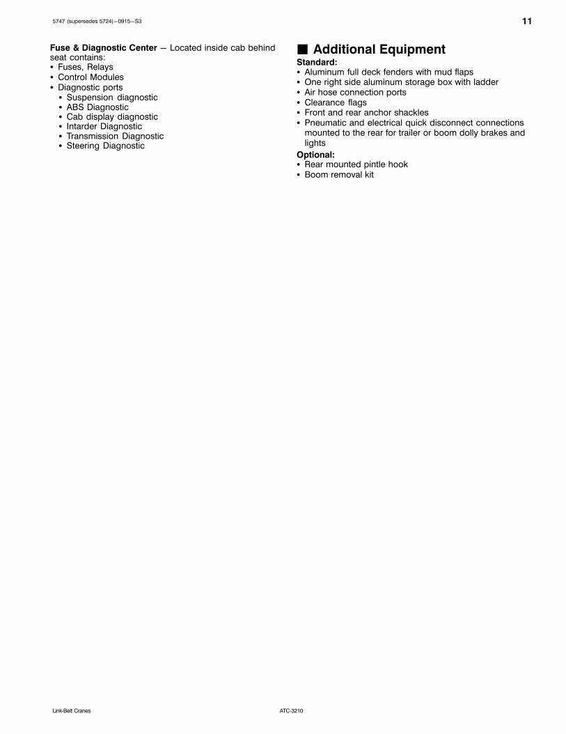
Fuse & Diagnostic Center - Located inside cab behindseat contains:� Fuses, Relays� Control Modules� Diagnostic ports� Suspension diagnostic� ABS Diagnostic� Cab display diagnostic� Intarder Diagnostic� Transmission Diagnostic� Steering Diagnostic
� Additional EquipmentStandard:� Aluminum full deck fenders with mud flaps� One right side aluminum storage box with ladder� Air hose connection ports� Clearance flags� Front and rear anchor shackles� Pneumatic and electrical quick disconnect connections
mounted to the rear for trailer or boom dolly brakes andlights
Optional:� Rear mounted pintle hook� Boom removal kit

12 5747 (supersedes 5724)-0915-S3
ATC‐3210 Link‐Belt Cranes
Axle Loads - English
Base crane with full tanks of fuel and no counterweight
GrossVehicleWeight
(1)
Axle 1 Axle 2 Axle 3 Axle 4 Axle 5
lb lb lb lb lb lb
123,812 24,953 24,478 24,397 25,091 24,891
Driver in carrier cab 250 177 177 34 34 34
Remove pontoons 431 15 15 134 134 134
Ether injector 5 4 4 1 1 1
Rear pintle hook 44 13 13 23 23 23
16.00R25 445/95R25) tires (instead of standard) 1,008 202 202 202 202 202
Carrier cab strobe light 5 4 4 1 1 1
Hoist drum follower - auxiliary 96 25 25 49 49 49
Auxiliary winch with 700 ft (213m) of 7/8" (22mm) wire rope 3,102 959 959 1,673 1,673 1,673
Remove auxiliary winch with 700 ft (213m) of 7/8" (22mm) wire rope 2,886 915 915 1,572 1,572 1,572
Rear winch roller 96 36 36 56 56 56
Remove 950 ft (289.5m) of wire rope from front (main) winch 1,454 334 334 707 707 707
Remove 700 ft (213mm) of wire rope from rear (auxiliary) winch 1,071 292 292 552 552 552
Substitute 700 ft (213mm) of rope with 950 ft (289.5m) of rope rear (auxiliary)
383 104 104 197 197 197
Substitute 950 ft (289.5m) of rope with 700 ft (213m) of rope front(main)
383 ‐88 ‐88 186 186 186
360° mechanical swing lock 151 52 52 85 85 85
Boom launching option 125 20 20 55 55 55
Floodlight to the front of the boom base section 17 6 6 2 2 2
Fly mounting brackets to boom base section for fly options 237 110 110 5 5 5
12 ft (3.7m) manual and hydraulically offsettable, lattice fly stowed 2,273 1,742 1,742 404 404 404
1240 ft (3.712.2m) manual and hydraulically offsettable, twopiece(bifold) lattice fly stowed
3,812 2,187 2,187 187 187 187
124067 ft (3.712.220.4m) manual and hydraulically offsettable,threepiece (bifold) lattice fly stowed
4,995 2,452 2,452 30 30 30
Additional components for hydraulically offsettable fly 389 223 223 ‐19 ‐19 ‐19
Auxiliary lifting sheave 112 103 103 32 32 32
35 ton (31.8t) 1 sheave hook block at front bumper 1,100 855 855 204 204 204
66 ton (60t) 3 sheave hook block at front bumper 1,900 1,478 1,478 352 352 352
100 ton (91t) 5 sheave hook block at front bumper 2,250 1,750 1,750 417 417 417
140 ton (127t) 7 sheave hook block at front bumper 2,850 2,216 2,216 528 528 528
210 ton (190.5t) 10 sheave hook block at front bumper 3,745 2,913 2,913 693 693 693
12 ton (10.9t) hookball at front bumper 722 562 562 134 134 134
(1) Adjust gross vehicle weight and axle loading according to component weight. All weights are ±3%.
Tire Maximum Axle Load @ 50 mph Average Speed
20.5R25 (525/80R25) on aluminum disc wheels 28,004 lb
16.00R25 (445/95R25) on aluminum disc wheels 29,224 lb
135747 (supersedes 5724)-0915-S3
ATC‐3210Link‐Belt Cranes
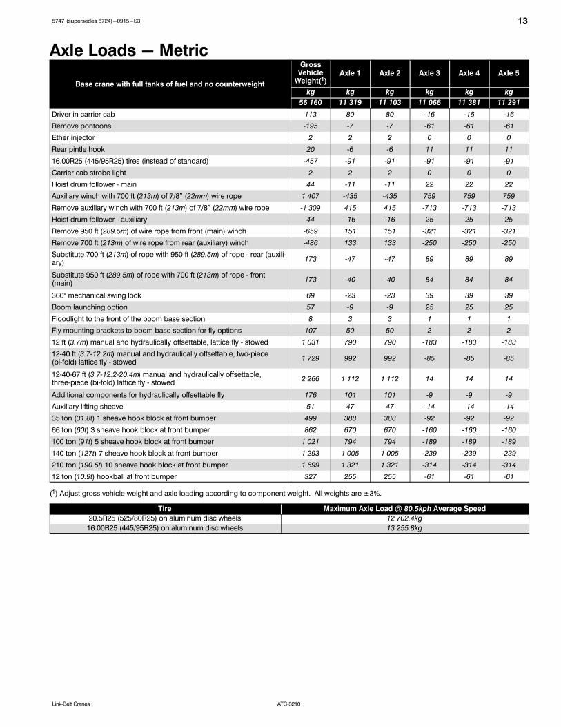
Axle Loads - Metric
Base crane with full tanks of fuel and no counterweight
GrossVehicle
Weight(1)Axle 1 Axle 2 Axle 3 Axle 4 Axle 5
kg kg kg kg kg kg
56 160 11 319 11 103 11 066 11 381 11 291
Driver in carrier cab 113 80 80 16 16 16
Remove pontoons 195 7 7 61 61 61
Ether injector 2 2 2 0 0 0
Rear pintle hook 20 6 6 11 11 11
16.00R25 (445/95R25) tires (instead of standard) 457 91 91 91 91 91
Carrier cab strobe light 2 2 2 0 0 0
Hoist drum follower main 44 11 11 22 22 22
Auxiliary winch with 700 ft (213m) of 7/8" (22mm) wire rope 1 407 435 435 759 759 759
Remove auxiliary winch with 700 ft (213m) of 7/8" (22mm) wire rope 1 309 415 415 713 713 713
Hoist drum follower auxiliary 44 16 16 25 25 25
Remove 950 ft (289.5m) of wire rope from front (main) winch 659 151 151 321 321 321
Remove 700 ft (213m) of wire rope from rear (auxiliary) winch 486 133 133 250 250 250
Substitute 700 ft (213m) of rope with 950 ft (289.5m) of rope rear (auxiliary)
173 47 47 89 89 89
Substitute 950 ft (289.5m) of rope with 700 ft (213m) of rope front(main)
173 ‐40 ‐40 84 84 84
360° mechanical swing lock 69 23 23 39 39 39
Boom launching option 57 9 9 25 25 25
Floodlight to the front of the boom base section 8 3 3 1 1 1
Fly mounting brackets to boom base section for fly options 107 50 50 2 2 2
12 ft (3.7m) manual and hydraulically offsettable, lattice fly stowed 1 031 790 790 183 183 183
1240 ft (3.712.2m) manual and hydraulically offsettable, twopiece(bifold) lattice fly stowed
1 729 992 992 ‐85 85 85
124067 ft (3.712.220.4m) manual and hydraulically offsettable,threepiece (bifold) lattice fly stowed
2 266 1 112 1 112 14 14 14
Additional components for hydraulically offsettable fly 176 101 101 ‐9 ‐9 ‐9
Auxiliary lifting sheave 51 47 47 14 14 14
35 ton (31.8t) 1 sheave hook block at front bumper 499 388 388 92 ‐92 92
66 ton (60t) 3 sheave hook block at front bumper 862 670 670 160 160 160
100 ton (91t) 5 sheave hook block at front bumper 1 021 794 794 189 189 189
140 ton (127t) 7 sheave hook block at front bumper 1 293 1 005 1 005 239 239 239
210 ton (190.5t) 10 sheave hook block at front bumper 1 699 1 321 1 321 314 314 314
12 ton (10.9t) hookball at front bumper 327 255 255 61 61 61
(1) Adjust gross vehicle weight and axle loading according to component weight. All weights are ±3%.
Tire Maximum Axle Load @ 80.5kph Average Speed
20.5R25 (525/80R25) on aluminum disc wheels 12 702.4kg
16.00R25 (445/95R25) on aluminum disc wheels 13 255.8kg

14 5747 (supersedes 5724)-0915-S3
ATC‐3210 Link‐Belt Cranes
Axle Loads with 2-Axle or 3-Axle Boom Dolly(3rd Axle Down) - English
Base crane with full tanks of fuel and no counterweight
GrossVehicle
Weight(1)Axle 1 Axle 2 Axle 3 Axle 4 Axle 5 Dolly
lb lb lb lb lb lb lb
123,812 19,765 19,290 19,985 20,679 20,479 23,614
Nelson 2 axle boom dolly (2) 6,600 0 0 0 0 0 6,600
Nelson 3 axle boom dolly (2) 9,000 0 0 0 0 0 9,000
Driver in carrier cab 250 177 177 34 34 34 0
Remove pontoons 431 15 15 134 134 134 0
Ether injector 5 4 4 1 1 1 0
Rear pintle hook 44 13 13 23 23 23 0
16.00R25 (445/95R25) tires (instead of standard) 1,008 202 202 202 202 202 0
Carrier cab strobe light 5 4 4 1 1 1 0
Hoist drum follower main 96 30 30 12 12 12 0
Auxiliary winch with 700 ft (213m) of 7/8" (22mm) wire rope 3,102 1,133 1,133 279 279 279 0
Remove auxiliary winch with 700 ft (213m) of 7/8" (22mm)wire rope
2,886 1,077 1,077 244 244 244 0
Hoist drum follower auxiliary 96 41 41 4 4 4 0
Remove 950 ft (289.5m) of wire rope from front (main) winch 1,454 416 416 207 207 207 0
Remove 700 ft (213m) of wire rope from rear (auxiliary)winch
1,071 353 353 122 122 122 0
Substitute 700 ft (213m) of rope with 950 ft (289.5m) of rope rear (auxiliary)
383 126 126 44 44 44 0
Substitute 950 ft (289.5m) of rope with 700 ft (213m) of rope front (main)
383 109 109 55 55 55 1
360° mechanical swing lock 151 60 60 10 10 10 0
Boom launching option 125 6 6 38 38 38 0
Floodlight to the front of the boom base section 17 2 2 1 1 1 10
Fly mounting brackets to boom base section for fly options 237 15 15 11 11 11 173
12 ft (3.7m) manual and hydraulically offsettable, lattice fly stowed
2,273 39 39 30 30 30 2,441
1240 ft (3.712.2m) manual and hydraulically offsettable,twopiece (bifold) lattice fly stowed
3,812 130 130 98 98 98 3,258
124067 ft (3.712.220.4m) manual and hydraulically offsettable, threepiece (bifold) lattice fly stowed
4,995 280 280 212 212 212 3,799
Additional components for hydraulically offsettable fly 389 13 13 10 10 10 333
Auxiliary lifting sheave 112 7 7 5 5 5 141
35 ton (31.8t) 1 sheave hook block at boom head 1,100 55 55 42 42 42 1,335
66 ton (60t) 3 sheave hook block at boom head 1,900 95 95 72 72 72 2,305
100 ton (91t) 5 sheave hook block at boom head 2,250 112 112 85 85 85 2,730
140 ton (127t) 7 sheave hook block at boom head 2,850 142 142 108 108 108 3,458
210 ton (190.5t) 10 sheave hook block at front bumper 3,745 187 187 142 142 142 4,544
12 ton (10.9t) hookball at boom head 722 36 36 27 27 27 876
(1) Adjust gross vehicle weight and axle loading according to component weight. All weights are ±3%.(2) Weights may vary.
Tire Maximum Axle Load @ 50 mph Average Speed
20.5R25 (525/80R25) on aluminum disc wheels 28,004 lb
16.00R25 (445/95R25) on aluminum disc wheels 29,224 lb

155747 (supersedes 5724)-0915-S3
ATC‐3210Link‐Belt Cranes
Axle Loads with 2-Axle or 3-Axle Boom Dolly(3rd Axle Down) - Metric
Base crane with full tanks of fuel and no counterweight
GrossVehicle
Weight(1)Axle 1 Axle 2 Axle 3 Axle 4 Axle 5 Dolly
kg kg kg kg kg kg kg
56 160 8 965 8 750 9 065 9 380 9 289 10 711
Nelson 2 axle boom dolly (2) 2 994 0 0 0 0 0 2 994
Nelson 2 axle boom dolly (2) 4 082 0 0 0 0 0 4 082
Driver in carrier cab 113 80 80 16 16 16 0
Remove pontoons 195 7 7 61 61 61 0
Ether injector 2 2 2 0 0 0 0
Rear pintle hook 20 6 6 11 11 11 0
16.00R25 (445/95R25) tires (instead of standard) 457 91 91 91 91 91 0
Carrier cab strobe light 2 2 2 0 0 0 0
Hoist drum follower main 44 14 14 5 5 5 0
Auxiliary winch with 700 ft (213m) of 7/8" (22mm) wire rope 1 407 514 514 126 126 126 0
Remove auxiliary winch with 700 ft (213m) of 7/8" (22mm)wire rope
1 309 488 488 111 111 111 0
Hoist drum follower auxiliary 44 19 19 2 2 2 0
Remove 950 ft (289.5m) of wire rope from front (main) winch 659 189 189 94 94 94 0
Remove 700 ft (213m) of wire rope from rear (auxiliary)winch
486 160 160 55 55 55 0
Substitute 700 ft (213m) of rope with 950 ft (289.5m) of rope rear (auxiliary)
173 57 57 20 20 20 0
Substitute 950 ft (289.5m) of rope with 700 ft (213m) of rope front (main)
173 50 50 25 25 25 0
360° mechanical swing lock 69 27 27 5 5 5 0
Boom launching option 57 3 3 17 17 17 0
Floodlight to the front of the boom base section 8 1 1 1 1 1 5
Fly mounting brackets to boom base section for fly options 107 7 7 5 5 5 79
12 ft (3.7m) manual and hydraulically offsettable, lattice fly stowed
1 031 18 18 14 14 14 1 107
1240 ft (3.712.2m) manual and hydraulically offsettable,twopiece (bifold) lattice fly stowed
1 729 59 59 45 45 45 1 478
124067 ft (3.712.220.4m) manual and hydraulically offsettable, threepiece (bifold) lattice fly stowed
2 266 127 127 96 96 96 1 723
Additional components for hydraulically offsettable fly 176 6 6 5 5 5 151
Auxiliary lifting sheave 51 3 3 2 2 2 64
35 ton (31.8t) 1 sheave hook block at boom head 499 25 25 19 19 19 605
66 ton (60t) 3 sheave hook block at boom head 862 43 43 33 33 33 1 046
100 ton (91t) 5 sheave hook block at boom head 1 021 51 51 39 39 39 1 238
140 ton (127t) 7 sheave hook block at boom head 1 293 65 65 49 49 49 1 569
12 ton (10.9t) hookball at boom head 327 16 16 12 12 12 397
(1) Adjust gross vehicle weight and axle loading according to component weight. All weights are ±3%.(2) Weights may vary.
Tire Maximum Axle Load @ 80.5kph Average Speed
20.5R25 (525/80R25) on aluminum disc wheels 12 702.4kg
16.00R25 (445/95R25) on aluminum disc wheels 13 255.8kg

16 5747 (supersedes 5724)-0915-S3
ATC‐3210 Link‐Belt Cranes
General Dimensions
12' 9.01”(3.89m)
(0.36m)1' 2.”
15' 5.82”(4.72m)
10' 8.44”(3.26m)
2020
(0.68m)2' 2.7”
44' 7.35”(13.60m)
9' 2.23”(2.80m)
5' 4”(1.63m)
5' 3.99”(1.63m)
5' 4”(1.63m)
6' 8.13”(2.04m)
11' 6”(3.51m)
12'(3.66m)
1' 2.24”(0.36m)1' 4.3”
(0.41m)
6' 7.01”(2.01m)
5' 10.06”(1.78m)
12' 6.45”(3.82m)
51' 2.93” (15.62m)Overall Length With Front Winch
53' 4.3” (16.23m)Overall Length With Rear Winch
53' 8.16” (16.36m)Overall Length With Counterweight
8' 6.63” (2.61m)
Not To Scale
English Metric
Wall to wall over carrier 41”.6” 12.6m
Wall to wall over boom 42' 2” 12.8m
Wall to wall over boom attachment 44' 6” 13.5m
Curb to curb 36' 3” 11.04m
Centerline of tire 35' 6” 10.8m
Tail Swing English Metric
With auxiliary winch 16' 11” 5.1m
Without auxiliary winch 14' 8” 4.7m
English Metric
42' 0” 12.8m
42' 6” 12.9m
44' 11” 13.7m
37' 1” 11.3m
36' 2” 11.0m
Turning Radius16.00R2520.5R25
Overall Width English Metric
With 14,000 lb (6.3t) counterweight 9' 10” 3.0m
-0.5°
With Counterweight 17' 1” 5.21m
With 36,000-115,000 lb (16.3t-52.4t) counterweight 10' 3” 3.1m
68' 1.19”(20.76m)
62' 4.72” (19.02m)Rear Dolly Connection
56' 4.34” (10.20m)Front Dolly Connection
1' 9.51”(0.55m)
13' 1.46”(4.00m)
6' 10.16”(2.09m)
44' 3.02”(13.49m)
LC Of Rotation
12' 10.36”(3.92m)
17' 0” (5.18m)Intermediate Extended
8' 9” (2.67m)Fully Retracted
10.45”(0.27m)
1' 10.5”(0.57m)
25' 6” (7.77m)Fully Extended
8' 0.69” (2.46m) Of TireLC

175747 (supersedes 5724)-0915-S3
ATC‐3210Link‐Belt Cranes
Working Range Diagram - Main BoomH
eig
ht
In F
eet
Ab
ove G
rou
nd
Operating Radius From Centerline of Rotation In Feet
Bo
om
Len
gth
In
Fe
et
20
44.3
C RotationL
7'-6”9'-6”
10
0
20
30
40
50
60
70
80
90
100
110
120
130
140
150
160
170
180
190
200
210
220
83� Max.Boom Angle
58.9
73.5
92.5 EM7
107.6
122.2 EM6
124.1 EM5
136.8
153.4 EM4
168.5 EM3
63.80 EM2
200.1 EM1
30405060708090100110120130140150160170180190200
10°
20°
30°
40°
50°
60°
70°

18 5747 (supersedes 5724)-0915-S3
ATC‐3210 Link‐Belt Cranes
Working Range Diagram - Main Boom + Fly
20°
30°
40°
50°
10°
60°70°
Heig
ht
In F
eet
Ab
ove G
rou
nd
Operating Radius From Centerline of Rotation In Feet
Bo
om
Len
gth
In
Fe
et
20C RotationL
7'-6”
10
0
20
30
40
50
60
70
80
90
100
110
120
130
140
150
160
170
180
190
200
210
220
83� Max.Boom Angle
168.5 + 12
30
40
50
60
70
80
90
100
110
120
130
140
150
160
170
180
190
200
230
240
250
260
270
280
290
300
310
320
330
340
210
220
230
240
250
260
270
280
290
300
310
320
2° Offset
15° Offset
30° Offset
45° Offset
185.5 + 12
168.5 + 40200.1 + 12
185.5 + 40
168.5 + 67200.1 + 40
185.5 + 67
168.5 + 92
200.1 + 67
200.1 + 117
185.5 + 117
200.1 + 92
168.5 + 117
185.5 + 92

195747 (supersedes 5724)-0915-S3
ATC‐3210Link‐Belt Cranes
Boom Extend Modes
BaseT5 T4 T3 T2 T1
Boom Length Telescope Length
ft m T5 T4 T3 T2 T1
44.3 13.5
73.5 22.4 100%
103.8 31.6 100% 100%
134.9 41.1 100% 100% 100%
167.1 50.9 100% 100% 100% 100%
183.6 56.0 100% 100% 100% 100% 50%
200.1 61.0 100% 100% 100% 100% 100%
Boom Length Telescope Length
ft m T5 T4 T3 T2 T1
44.3 13.5
73.5 22.4 100%
103.8 31.6 100% 100%
119.3 36.4 100% 100% 50%
135.4 41.3 100% 100% 50% 50%
152.0 46.3 100% 100% 50% 50% 50%
168.5 51.4 100% 100% 50% 50% 100%
Boom Length Telescope Length
ft m T5 T4 T3 T2 T1
44.3 13.5
58.9 18.0 50%
74.0 22.6 50% 50%
89.6 27.3 50% 50% 50%
105.7 32.2 50% 50% 50% 50%
122.2 37.3 50% 50% 50% 50% 50%
Boom Length Telescope Length
ft m T5 T4 T3 T2 T1
44.3 13.5
59.9 18.3 50%
75.9 23.1 50% 50%
92.5 28.2 50% 50% 50%
Boom Length Telescope Length
ft m T5 T4 T3 T2 T1
44.3 13.5
58.9 18.0 50%
89.1 27.2 50% 100%
120.3 36.7 50% 100% 100%
152.4 46.5 50% 100% 100% 100%
169.0 51.5 50% 100% 100% 100% 50%
185.5 56.5 50% 100% 100% 100% 100%
Boom Length Telescope Length
ft m T5 T4 T3 T2 T1
44.3 13.5
73.5 22.4 100%
88.6 27.0 100% 50%
104.2 31.8 100% 50% 50%
120.3 36.7 100% 50% 50% 50%
136.8 41.7 100% 50% 50% 50% 50%
153.4 46.8 100% 50% 50% 50% 100%
Boom Length Telescope Length
ft m T5 T4 T3 T2 T1
44.3 13.5
59.4 18.1 50%
75.0 22.9 50% 50%
91.0 27.7 50% 50% 50%
107.6 32.8 50% 50% 50% 50%
124.1 37.8 50% 50% 50% 50%

20 5747 (supersedes 5724)-0915-S3
ATC‐3210 Link‐Belt Cranes
Main Boom Lift Capacity Charts - Standard0 lb Counterweight Fully Extended Outriggers 360° Rotation
(All Capacities Are Listed In Pounds)
Radius (ft)
Boom Length (ft)Radius (ft)
44.27 58.9-59.8 73.5-75.9 88.6-92.4 103.7-107.5 119.3-124.1 134.9-136.8 151.9-153.3
10 276,600 278,200 262,200 212,200 10
12 244,100 247,500 245,100 212,200 12
15 195,400 199,400 200,100 198,500 128,900 15
20 144,300 148,500 149,700 149,200 147,400 120,900 91,400 20
25 86,100 94,600 98,000 98,700 97,400 94,600 91,400 65,300 25
30 55,200 63,000 67,100 68,700 68,700 67,500 65,600 65,300 30
35 37,900 45,500 49,200 50,700 51,700 51,500 51,400 48,500 35
40 34,300 37,800 39,200 40,100 39,900 39,800 37,100 40
45 26,400 30,100 31,400 32,300 32,100 32,000 29,500 45
50 20,600 24,300 25,600 26,400 26,300 26,200 23,800 50
55 19,700 21,200 22,000 21,800 21,700 19,400 55
60 16,200 17,600 18,400 18,300 18,200 16,200 60
65 12,500 14,800 15,700 15,700 15,600 13,400 65
70 12,400 13,400 13,300 13,200 11,100 70
75 10,400 11,300 11,300 11,300 9,200 75
80 8,700 9,600 9,700 9,600 7,500 80
85 8,100 8,200 8,200 6,100 85
90 6,800 6,900 6,900 4,900 90
95 5,700 5,700 5,800 3,800 95
100 4,700 4,800 2,900 100
105 3,800 3,900 105
110 3,100 3,100 110
115 2,300 115
Note: Capacities depict multiple boom modes.
This information is not for crane operation. Operator must refer to the in-cab information for crane operation. Ratedlifting capacities shown on fully extended outriggers do not exceed 85% of the tipping loads.
215747 (supersedes 5724)-0915-S3
ATC‐3210Link‐Belt Cranes
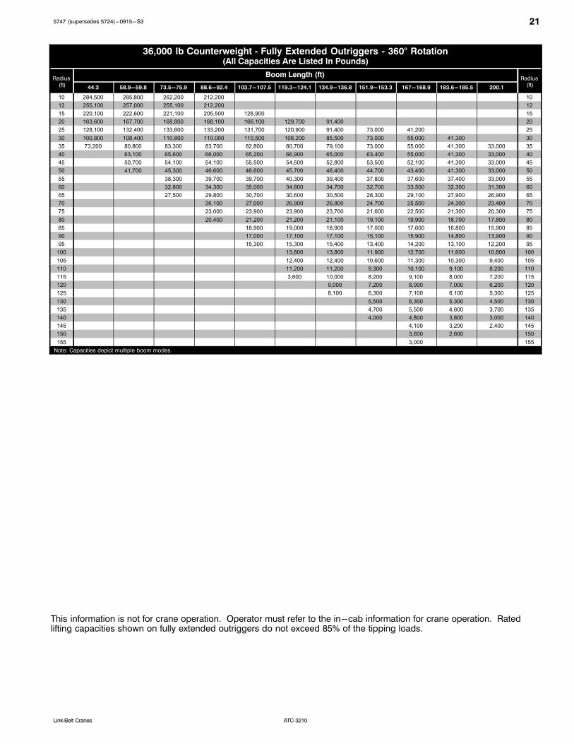
36,000 lb Counterweight Fully Extended Outriggers 360° Rotation(All Capacities Are Listed In Pounds)
Radius (ft)
Boom Length (ft)Radius
(ft)44.3 58.9-59.8 73.5-75.9 88.6-92.4 103.7-107.5 119.3-124.1 134.9-136.8 151.9-153.3 167-168.9 183.6-185.5 200.1
10 284,500 285,800 262,200 212,200 10
12 255,100 257,000 255,100 212,200 12
15 220,100 222,600 221,100 205,500 128,900 15
20 163,600 167,700 168,800 168,100 166,100 129,700 91,400 20
25 128,100 132,400 133,600 133,200 131,700 120,900 91,400 73,000 41,200 25
30 100,800 108,400 110,800 110,000 110,500 108,200 85,500 73,000 55,000 41,300 30
35 73,200 80,800 83,300 83,700 82,800 80,700 79,100 73,000 55,000 41,300 33,000 35
40 63,100 65,600 66,000 65,200 66,900 65,000 63,400 55,000 41,300 33,000 40
45 50,700 54,100 54,100 55,500 54,500 52,800 53,500 52,100 41,300 33,000 45
50 41,700 45,300 46,600 46,600 45,700 46,400 44,700 43,400 41,300 33,000 50
55 38,300 39,700 39,700 40,300 39,400 37,800 37,600 37,400 33,000 55
60 32,800 34,300 35,000 34,800 34,700 32,700 33,500 32,300 31,300 60
65 27,500 29,800 30,700 30,600 30,500 28,300 29,100 27,900 26,900 65
70 26,100 27,000 26,900 26,800 24,700 25,500 24,300 23,400 70
75 23,000 23,900 23,900 23,700 21,600 22,500 21,300 20,300 75
80 20,400 21,200 21,200 21,100 19,100 19,900 18,700 17,800 80
85 18,900 19,000 18,900 17,000 17,600 16,800 15,900 85
90 17,000 17,100 17,100 15,100 15,900 14,800 13,900 90
95 15,300 15,300 15,400 13,400 14,200 13,100 12,200 95
100 13,800 13,800 11,900 12,700 11,600 10,800 100
105 12,400 12,400 10,600 11,300 10,300 9,400 105
110 11,200 11,200 9,300 10,100 9,100 8,200 110
115 3,600 10,000 8,200 9,100 8,000 7,200 115
120 9,000 7,200 8,000 7,000 6,200 120
125 8,100 6,300 7,100 6,100 5,300 125
130 5,500 6,300 5,300 4,500 130
135 4,700 5,500 4,600 3,700 135
140 4,000 4,800 3,800 3,000 140
145 4,100 3,200 2,400 145
150 3,600 2,600 150
155 3,000 155
Note: Capacities depict multiple boom modes.
This information is not for crane operation. Operator must refer to the in-cab information for crane operation. Ratedlifting capacities shown on fully extended outriggers do not exceed 85% of the tipping loads.
22 5747 (supersedes 5724)-0915-S3
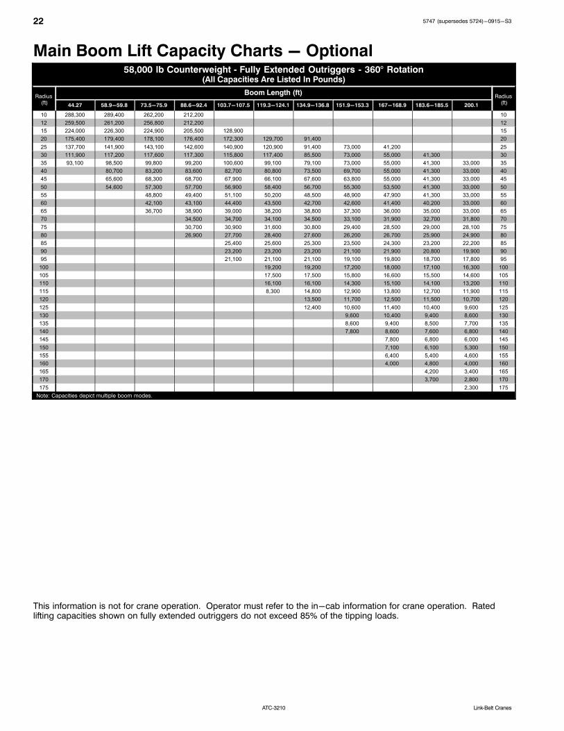
ATC‐3210 Link‐Belt Cranes
Main Boom Lift Capacity Charts - Optional58,000 lb Counterweight Fully Extended Outriggers 360° Rotation
(All Capacities Are Listed In Pounds)
Radius (ft)
Boom Length (ft)Radius
(ft)44.27 58.9-59.8 73.5-75.9 88.6-92.4 103.7-107.5 119.3-124.1 134.9-136.8 151.9-153.3 167-168.9 183.6-185.5 200.1
10 288,300 289,400 262,200 212,200 10
12 259,500 261,200 256,800 212,200 12
15 224,000 226,300 224,900 205,500 128,900 15
20 175,400 179,400 178,100 176,400 172,300 129,700 91,400 20
25 137,700 141,900 143,100 142,600 140,900 120,900 91,400 73,000 41,200 25
30 111,900 117,200 117,600 117,300 115,800 117,400 85,500 73,000 55,000 41,300 30
35 93,100 98,500 99,800 99,200 100,600 99,100 79,100 73,000 55,000 41,300 33,000 35
40 80,700 83,200 83,600 82,700 80,800 73,500 69,700 55,000 41,300 33,000 40
45 65,600 68,300 68,700 67,900 66,100 67,600 63,800 55,000 41,300 33,000 45
50 54,600 57,300 57,700 56,900 58,400 56,700 55,300 53,500 41,300 33,000 50
55 48,800 49,400 51,100 50,200 48,500 48,900 47,900 41,300 33,000 55
60 42,100 43,100 44,400 43,500 42,700 42,600 41,400 40,200 33,000 60
65 36,700 38,900 39,000 38,200 38,800 37,300 36,000 35,000 33,000 65
70 34,500 34,700 34,100 34,500 33,100 31,900 32,700 31,800 70
75 30,700 30,900 31,600 30,800 29,400 28,500 29,000 28,100 75
80 26,900 27,700 28,400 27,600 26,200 26,700 25,900 24,900 80
85 25,400 25,600 25,300 23,500 24,300 23,200 22,200 85
90 23,200 23,200 23,200 21,100 21,900 20,800 19,900 90
95 21,100 21,100 21,100 19,100 19,800 18,700 17,800 95
100 19,200 19,200 17,200 18,000 17,100 16,300 100
105 17,500 17,500 15,800 16,600 15,500 14,600 105
110 16,100 16,100 14,300 15,100 14,100 13,200 110
115 8,300 14,800 12,900 13,800 12,700 11,900 115
120 13,500 11,700 12,500 11,500 10,700 120
125 12,400 10,600 11,400 10,400 9,600 125
130 9,600 10,400 9,400 8,600 130
135 8,600 9,400 8,500 7,700 135
140 7,800 8,600 7,600 6,800 140
145 7,800 6,800 6,000 145
150 7,100 6,100 5,300 150
155 6,400 5,400 4,600 155
160 4,000 4,800 4,000 160
165 4,200 3,400 165
170 3,700 2,800 170
175 2,300 175
Note: Capacities depict multiple boom modes.
This information is not for crane operation. Operator must refer to the in-cab information for crane operation. Ratedlifting capacities shown on fully extended outriggers do not exceed 85% of the tipping loads.
235747 (supersedes 5724)-0915-S3
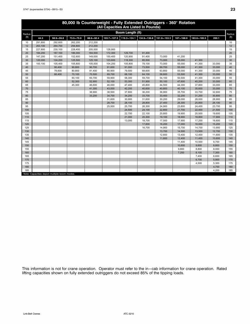
ATC‐3210Link‐Belt Cranes
80,000 lb Counterweight Fully Extended Outriggers 360° Rotation(All Capacities Are Listed In Pounds)
Radius (ft)
Boom Length (ft)Radius
(ft)44.3 58.9-59.8 73.5-75.9 88.6-92.4 103.7-107.5 119.3-124.1 134.9-136.8 151.9-153.3 167-168.9 183.6-185.5 200.1
10 291,800 292,600 262,200 212,200 10
12 263,100 264,700 256,800 212,200 12
15 227,800 230,100 228,400 205,500 128,900 15
20 184,200 187,100 186,000 184,500 172,300 129,700 91,400 20
25 147,200 151,400 152,600 149,000 150,400 120,900 91,400 73,000 41,200 25
30 120,000 124,200 125,500 125,100 123,600 118,300 85,500 73,000 55,000 41,300 30
35 100,100 105,400 105,800 105,500 104,200 105,800 79,100 73,000 55,000 41,300 33,000 35
40 90,400 90,800 90,700 91,600 91,000 73,500 69,700 55,000 41,300 33,000 40
45 78,600 80,800 81,400 80,900 79,500 68,600 63,800 55,000 41,300 33,000 45
50 66,400 70,100 70,500 69,700 68,100 64,100 58,600 53,500 41,300 33,000 50
55 60,100 60,700 59,900 58,300 59,700 54,100 50,500 41,300 33,000 55
60 52,300 52,900 52,100 53,300 51,900 50,100 47,600 40,200 33,000 60
65 45,300 46,600 46,000 47,400 45,800 44,500 44,300 37,800 33,000 65
70 41,300 43,000 42,200 40,600 40,800 40,100 35,600 33,000 70
75 36,900 38,500 37,800 36,200 36,900 35,700 33,700 32,600 75
80 33,200 34,700 34,200 33,700 33,400 32,200 31,200 30,800 80
85 31,600 30,900 31,600 30,200 29,000 28,000 28,900 85
90 28,700 28,100 28,800 27,400 26,300 25,800 26,100 90
95 25,500 25,700 26,300 24,900 23,800 24,400 23,700 95
100 24,500 24,100 22,800 21,700 22,400 21,500 100
105 22,700 22,100 20,800 19,900 20,500 19,600 105
110 21,000 20,300 19,100 18,900 18,800 17,900 110
115 13,000 18,700 17,500 17,900 17,200 16,600 115
120 17,600 16,200 17,000 16,000 15,200 120
125 16,700 14,900 15,700 14,700 13,900 125
130 13,700 14,500 13,500 12,700 130
135 12,600 13,400 12,400 11,600 135
140 11,600 12,400 11,400 10,600 140
145 11,400 10,500 9,700 145
150 10,600 9,600 8,800 150
155 9,800 8,800 8,000 155
160 7,200 8,100 7,300 160
165 7,400 6,600 165
170 6,700 5,900 170
175 4,500 5,300 175
180 4,700 180
185 4,200 185
Note: Capacities depict multiple boom modes.
This information is not for crane operation. Operator must refer to the in-cab information for crane operation. Ratedlifting capacities shown on fully extended outriggers do not exceed 85% of the tipping loads.

24 5747 (supersedes 5724)-0915-S3
ATC‐3210 Link‐Belt Cranes
102,000 lb Counterweight Fully Extended Outriggers 360° Rotation(All Capacities Are Listed In Pounds)
Radius (ft)
Boom Length (ft)Radius
(ft)44.3 58.9-59.8 73.5-75.9 88.6-92.4 103.7-107.5 119.3-124.1 134.9-136.8 151.9-153.3 167-168.9 183.6-185.5 200.1
10 295,200 295,700 262,200 212,200 10
12 266,300 267,700 256,800 212,200 12
15 231,400 233,500 231,800 205,500 128,900 15
20 187,400 190,300 189,100 184,600 172,300 129,700 91,400 20
25 156,100 159,200 158,300 157,100 153,000 120,900 91,400 73,000 41,200 25
30 128,000 132,300 133,500 131,200 131,600 118,300 85,500 73,000 55,000 41,300 30
35 107,000 111,400 112,700 112,500 111,100 107,800 79,100 73,000 55,000 41,300 33,000 35
40 96,500 97,000 96,800 95,500 97,100 73,500 69,700 55,000 41,300 33,000 40
45 84,100 84,600 84,400 83,900 84,900 68,600 63,800 55,000 41,300 33,000 45
50 73,100 76,200 76,400 76,300 74,900 64,100 58,600 53,500 41,300 33,000 50
55 68,000 68,600 68,100 66,800 60,400 54,100 50,500 41,300 33,000 55
60 61,100 61,700 61,200 59,900 57,000 50,100 47,600 40,200 33,000 60
65 53,200 55,700 55,100 53,500 54,000 46,500 44,300 37,800 33,000 65
70 49,700 49,200 47,700 49,000 43,300 41,400 35,600 33,000 70
75 44,600 44,100 45,200 44,000 40,500 38,700 33,700 32,600 75
80 39,500 39,800 41,200 39,700 37,900 36,400 31,900 30,800 80
85 36,800 37,500 36,000 34,900 34,200 30,200 29,100 85
90 34,900 34,300 33,000 33,300 32,200 28,600 27,600 90
95 30,000 31,400 30,100 30,800 29,700 27,200 26,200 95
100 28,900 27,600 28,300 27,200 25,800 25,000 100
105 26,700 26,300 26,000 25,000 24,000 23,800 105
110 24,700 25,200 24,000 23,000 22,000 22,400 110
115 17,700 23,400 22,200 21,200 20,200 21,000 115
120 21,800 20,500 19,500 18,900 19,400 120
125 20,300 19,000 18,000 18,000 17,900 125
130 17,700 16,800 17,200 16,800 130
135 16,500 15,500 16,400 15,600 135
140 15,400 14,400 15,200 14,400 140
145 13,300 14,100 13,300 145
150 12,700 13,100 12,300 150
155 12,100 12,200 11,400 155
160 10,200 11,300 10,500 160
165 10,500 9,700 165
170 9,800 9,000 170
175 7,500 8,300 175
180 7,600 180
185 7,000 185
Note: Capacities depict multiple boom modes.
This information is not for crane operation. Operator must refer to the in-cab information for crane operation. Ratedlifting capacities shown on fully extended outriggers do not exceed 85% of the tipping loads.

255747 (supersedes 5724)-0915-S3
ATC‐3210Link‐Belt Cranes
115,500 lb Counterweight Fully Extended Outriggers 360° Rotation(All Capacities Are Listed In Pounds)
Radius (ft)
Boom Length (ft)Radius
(ft)44.3 58.9-59.8 73.5-75.9 88.6-92.4 103.7-107.5 119.3-124.1 134.9-136.8 151.9-153.3 167-168.9 183.6-185.5 200.1
8 420,000 ** 8
10 300,000 297,300 262,200 212,200 10
12 268,200 269,500 256,800 212,200 12
15 233,200 235,200 232,200 205,500 128,900 15
20 189,400 192,100 191,000 184,600 172,300 129,700 91,400 20
25 157,800 160,900 160,000 158,700 153,000 120,900 91,400 73,000 41,200 25
30 133,000 137,200 136,300 135,000 136,500 118,300 85,500 73,000 55,000 41,300 30
35 111,300 115,700 117,000 116,700 115,300 107,800 79,100 73,000 55,000 41,300 33,000 35
40 99,400 100,700 100,500 99,200 98,900 73,500 69,700 55,000 41,300 33,000 40
45 87,400 87,800 87,700 86,500 88,000 68,600 63,800 55,000 41,300 33,000 45
50 76,100 77,500 77,400 77,400 77,900 64,100 58,600 53,500 41,300 33,000 50
55 70,700 70,800 70,800 69,400 60,400 54,100 50,500 41,300 33,000 55
60 63,700 64,200 63,800 62,400 57,000 50,100 47,600 40,200 33,000 60
65 55,900 58,200 57,700 56,300 54,000 46,500 44,300 37,800 33,000 65
70 53,000 52,500 51,300 51,300 43,300 41,400 35,600 33,000 70
75 48,500 48,000 46,800 48,100 40,500 38,700 33,700 32,600 75
80 42,200 44,100 42,900 44,100 37,900 36,400 31,900 30,800 80
85 40,100 40,900 40,100 35,600 34,200 30,200 29,100 85
90 36,600 38,000 36,600 33,400 32,200 28,600 27,600 90
95 33,600 34,900 33,700 31,700 30,300 27,200 26,200 95
100 32,300 31,000 30,400 28,600 25,800 25,000 100
105 29,900 28,500 29,100 27,100 24,400 23,800 105
110 25,000 26,400 27,100 25,600 23,000 22,400 110
115 20,600 24,400 25,100 24,100 21,600 21,400 115
120 23,300 23,300 22,300 20,400 20,400 120
125 21,000 21,700 20,700 19,400 19,600 125
130 20,200 19,200 18,300 18,700 130
135 18,800 17,800 17,100 17,700 135
140 17,600 16,700 15,900 16,700 140
145 15,500 15,000 15,600 145
150 14,500 14,400 14,500 150
155 13,500 13,800 13,500 155
160 10,200 13,200 12,500 160
165 12,500 11,700 165
170 11,700 10,800 170
175 9,300 10,100 175
180 9,400 180
185 8,700 185
Note: Capacities depict multiple boom modes.** Over rear intermediate outriggers, additional equipment required.
This information is not for crane operation. Operator must refer to the in-cab information for crane operation. Ratedlifting capacities shown on fully extended outriggers do not exceed 85% of the tipping loads.

26 5747 (supersedes 5724)-0915-S3
ATC‐3210 Link‐Belt Cranes
Manual & Hydraulic Offset Fly Attachment Lift CapacityCharts - Optional
36,000 lb Counterweight Fully Extended Outriggers 360° Rotation(All Capacities Are Listed In Pounds)
Main Boom + 12 ft Offset Fly (Manual Offsets 2°, 15°, 30°, 45° & Hydraulic Offsets 2° 45°)
Radius(ft)
Main Boom Length (ft)Radius
(ft)44.3 58.9 73.5 89.1 103.7 119.3-120.3 134.9-135.4 151.9-152.4 167-168.9 183.6-185.5 200.1
10 69,600 69,500 69,400 69,400 10
12 69,600 69,500 69,400 69,400 12
15 69,600 69,500 69,400 69,400 62,700 61,000 15
20 69,600 69,500 69,400 69,400 62,700 61,000 42,600 20
25 69,600 69,500 69,400 69,400 61,800 61,000 55,600 55,000 43,000 25
30 66,700 69,500 64,100 62,300 55,000 58,300 55,600 55,000 43,000 35,400 28,400 30
35 61,800 69,400 57,500 56,000 49,400 52,600 55,600 55,000 43,000 35,400 28,100 35
40 57,700 64,900 51,300 50,700 45,000 48,000 51,100 53,400 43,000 35,400 28,100 40
45 49,700 52,600 46,300 46,300 41,100 44,300 47,200 49,600 43,000 35,400 28,100 45
50 43,800 42,600 42,600 37,700 40,900 43,900 43,600 42,200 35,400 28,100 50
55 37,000 38,800 38,700 34,800 37,900 38,400 36,700 35,300 34,100 28,100 55
60 31,800 33,500 33,400 32,200 34,100 33,200 31,600 32,300 31,000 28,100 60
65 29,100 29,000 30,000 29,700 29,400 27,200 27,900 26,700 25,600 65
70 25,500 25,400 26,400 26,100 25,800 23,600 24,300 23,100 22,000 70
75 22,600 22,400 23,300 23,000 22,700 20,600 21,200 20,000 19,000 75
80 19,800 20,700 20,400 20,100 18,000 18,700 17,500 16,800 80
85 17,600 18,500 18,200 17,900 16,000 16,700 15,500 14,600 85
90 15,800 16,700 16,400 16,100 14,100 14,700 13,600 12,700 90
95 15,000 14,600 14,400 12,400 13,000 11,900 11,000 95
100 13,500 13,100 12,900 10,900 11,500 10,400 9,500 100
105 12,200 11,800 11,500 9,600 10,200 9,100 8,200 105
110 10,600 10,300 8,400 9,000 7,900 7,000 110
115 9,500 9,300 7,300 7,900 6,800 5,900 115
120 8,600 8,300 6,300 6,900 5,900 4,900 120
125 7,400 5,400 6,000 5,000 4,100 125
130 6,600 4,600 5,200 4,200 3,300 130
135 5,900 3,900 4,500 3,400 2,500 135
140 3,200 3,800 2,700 140
145 2,600 3,200 2,100 145
150 2,600 150
155 2,100 155
Note: Capacities depict multiple boom modes.
This information is not for crane operation. Operator must refer to the in-cab information for crane operation. Ratedlifting capacities shown on fully extended outriggers do not exceed 85% of the tipping loads.
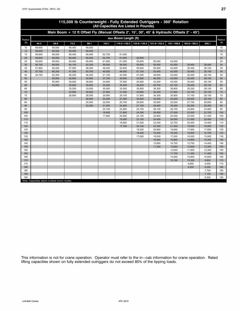
275747 (supersedes 5724)-0915-S3
ATC‐3210Link‐Belt Cranes
115,500 lb Counterweight Fully Extended Outriggers 360° Rotation(All Capacities Are Listed In Pounds)
Main Boom + 12 ft Offset Fly (Manual Offsets 2°, 15°, 30°, 45° & Hydraulic Offsets 2° 45°)
Radius (ft)
Main Boom Length (ft)Radius
(ft)44.3 58.9 73.5 89.1 103.7 119.3-120.3 134.9-135.4 151.9-152.4 167-168.9 183.6-185.5 200.1
10 69,600 69,500 69,400 69,400 10
12 69,600 69,500 69,400 69,400 12
15 69,600 69,500 69,400 69,400 62,700 61,000 15
20 69,600 69,500 69,400 69,400 62,700 61,000 42,600 20
25 69,600 69,500 69,400 69,400 61,800 61,000 55,600 55,000 43,000 25
30 66,700 69,500 64,100 62,300 55,000 58,300 55,600 55,000 43,000 35,400 28,400 30
35 61,800 69,400 57,500 56,000 49,400 52,600 55,600 55,000 43,000 35,400 28,100 35
40 57,700 66,200 51,300 50,700 45,000 48,000 51,100 53,400 43,000 35,400 28,100 40
45 54,700 62,300 46,300 46,300 41,100 44,300 47,200 49,600 43,000 35,400 28,100 45
50 59,000 42,600 42,600 37,700 40,900 43,900 46,300 43,000 35,400 28,100 50
55 55,900 39,000 38,900 34,800 37,900 40,900 43,300 43,000 35,400 28,100 55
60 53,000 35,900 35,800 32,200 35,300 38,200 40,700 42,100 35,400 28,100 60
65 33,200 33,000 30,000 33,000 35,900 38,300 39,800 35,200 28,100 65
70 30,900 30,600 27,900 31,000 33,800 36,200 37,800 33,100 28,100 70
75 28,900 28,500 25,900 29,100 31,900 34,300 35,900 31,100 28,100 75
80 26,600 24,200 27,400 30,200 32,500 34,200 29,400 28,100 80
85 25,000 22,600 25,700 28,600 30,900 32,500 27,700 26,800 85
90 23,500 21,500 24,200 27,100 29,400 30,500 26,200 25,300 90
95 20,100 22,800 25,700 28,100 28,700 24,800 23,900 95
100 18,900 21,800 24,300 26,800 27,000 23,500 22,700 100
105 17,900 20,600 23,100 25,600 25,400 22,000 21,400 105
110 19,500 22,100 24,400 24,000 21,000 20,400 110
115 18,600 21,000 23,300 22,700 20,000 19,400 115
120 17,700 20,100 22,300 21,200 19,000 18,400 120
125 19,200 20,800 19,600 17,900 17,500 125
130 18,400 19,300 18,200 16,900 16,700 130
135 17,600 18,000 17,000 16,000 15,900 135
140 16,900 15,800 14,800 15,200 140
145 15,800 14,700 13,700 14,400 145
150 11,300 13,600 12,600 13,300 150
155 12,600 11,900 12,300 155
160 11,700 11,300 11,400 160
165 10,900 10,800 10,600 165
170 10,100 10,300 9,800 170
175 9,800 9,000 175
180 9,200 8,300 180
185 7,700 185
190 7,100 190
195 6,500 195
Note: Capacities depict multiple boom modes.
This information is not for crane operation. Operator must refer to the in-cab information for crane operation. Ratedlifting capacities shown on fully extended outriggers do not exceed 85% of the tipping loads.

28 5747 (supersedes 5724)-0915-S3
ATC‐3210 Link‐Belt Cranes
Manual Offset Fly Attachment Lift Capacity Charts -Optional
36,000 lb Counterweight Fully Extended Outriggers 360° Rotation(All Capacities Are Listed In Pounds)
200.1 ft Main Boom Length
Radius(ft)
40 ft Manual Offset Fly 67 ft Manual Offset FlyRadius
(ft)2° 15° 30° 45° 2° 15° 30° 45°
35 35
40 16,100 40
45 16,100 16,100 10,800 45
50 16,100 16,100 10,800 50
55 16,100 16,100 10,800 55
60 16,100 16,100 15,900 10,800 60
65 16,100 16,100 15,900 15,600 10,800 10,800 65
70 16,100 16,100 15,900 15,600 10,800 10,800 70
75 16,100 16,100 15,900 15,600 10,800 10,800 75
80 16,100 16,100 15,900 15,600 10,800 10,800 10,700 80
85 15,700 16,100 15,900 15,600 10,800 10,800 10,700 85
90 13,700 14,900 15,900 15,600 10,800 10,800 10,700 90
95 12,000 13,100 14,200 15,000 10,800 10,800 10,700 10,300 95
100 10,500 11,500 12,500 13,300 10,800 10,800 10,700 10,100 100
105 9,100 10,100 11,000 11,700 9,900 10,800 10,700 9,900 105
110 7,900 8,800 9,600 10,300 8,700 10,200 10,700 9,800 110
115 6,800 7,600 8,400 9,000 7,600 9,000 10,500 9,600 115
120 5,800 6,600 7,300 7,900 6,600 7,900 9,300 9,500 120
125 4,900 5,600 6,300 6,800 5,700 6,900 8,200 9,300 125
130 4,100 4,800 5,400 5,900 4,800 6,000 7,200 8,200 130
135 3,300 4,000 4,600 5,000 4,000 5,200 6,300 7,200 135
140 2,600 3,200 3,800 4,200 3,300 4,400 5,500 6,300 140
145 2,600 3,100 3,400 2,700 3,700 4,700 5,500 145
150 2,400 2,700 2,100 3,000 4,000 4,700 150
155 2,100 2,400 3,300 3,900 155
160 2,700 3,300 160
165 2,100 2,600 165
This information is not for crane operation. Operator must refer to the in-cab information for crane operation. Ratedlifting capacities shown on fully extended outriggers do not exceed 85% of the tipping loads.

295747 (supersedes 5724)-0915-S3
ATC‐3210Link‐Belt Cranes
115,500 lb Counterweight Fully Extended Outriggers 360° Rotation(All Capacities Are Listed In Pounds)
200.1 ft Main Boom Length
Radius(ft)
40 ft Manual Offset Fly 67 ft Manual Offset FlyRadius
(ft)2° 15° 30° 45° 2° 15° 30° 45°
35 35
40 16,100 40
45 16,100 10,800 45
50 16,100 16,100 10,800 50
55 16,100 16,100 10,800 55
60 16,100 16,100 15,900 10,800 60
65 16,100 16,100 15,900 15,600 10,800 10,800 65
70 16,100 16,100 15,900 15,600 10,800 10,800 70
75 16,100 16,100 15,900 15,600 10,800 10,800 75
80 16,100 16,100 15,900 15,600 10,800 10,800 10,700 80
85 16,100 16,100 15,900 15,600 10,800 10,800 10,700 85
90 16,100 16,100 15,900 15,600 10,800 10,800 10,700 90
95 16,100 16,100 15,900 15,600 10,800 10,800 10,700 10,300 95
100 16,100 16,100 15,900 15,600 10,800 10,800 10,700 10,100 100
105 16,100 16,100 15,900 15,600 10,800 10,800 10,700 9,900 105
110 16,100 16,100 15,900 15,600 10,800 10,800 10,700 9,800 110
115 16,100 16,100 15,900 15,600 10,800 10,800 10,700 9,600 115
120 16,100 16,100 15,900 15,600 10,800 10,800 10,700 9,500 120
125 16,000 16,000 15,900 15,600 10,800 10,800 10,500 9,400 125
130 15,300 15,300 15,200 15,200 10,800 10,800 10,300 9,200 130
135 14,500 14,500 14,500 14,500 10,800 10,800 10,100 9,100 135
140 13,800 13,800 13,900 13,900 10,800 10,800 9,900 9,000 140
145 13,200 13,200 13,200 13,200 10,800 10,800 9,700 8,900 145
150 12,600 12,600 12,600 12,600 10,800 10,800 9,600 8,800 150
155 12,000 12,000 12,100 12,100 10,800 10,800 9,400 8,700 155
160 11,400 11,500 11,500 11,500 10,600 10,500 9,300 8,600 160
165 10,900 11,000 11,000 11,000 10,100 10,300 9,100 8,500 165
170 10,400 10,500 10,500 10,500 9,700 9,800 9,000 8,400 170
175 9,700 10,000 10,000 10,100 9,200 9,300 8,900 8,400 175
180 9,000 9,300 9,600 9,600 8,800 8,900 8,700 8,300 180
185 8,300 8,600 8,900 9,000 8,400 8,500 8,600 8,300 185
190 7,700 8,000 8,200 8,300 8,000 8,100 8,200 8,200 190
195 7,100 7,400 7,600 7,600 7,600 7,700 7,800 7,900 195
200 6,500 6,800 6,900 7,100 7,400 7,500 7,500 200
205 6,000 6,200 6,400 6,600 7,000 7,100 7,200 205
210 5,500 5,700 5,800 6,100 6,500 6,800 6,800 210
215 5,000 5,200 5,300 5,600 6,000 6,300 6,400 215
220 4,600 4,700 5,100 5,500 5,800 5,800 220
225 4,200 4,300 4,700 5,000 5,300 225
230 4,300 4,600 4,800 230
235 3,900 4,100 4,300 235
240 3,500 3,700 3,800 240
245 3,100 3,300 3,400 245
250 2,800 2,900 250
This information is not for crane operation. Operator must refer to the in-cab information for crane operation. Ratedlifting capacities shown on fully extended outriggers do not exceed 85% of the tipping loads.
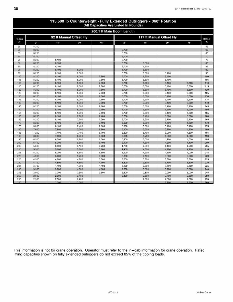
30 5747 (supersedes 5724)-0915-S3
ATC‐3210 Link‐Belt Cranes
115,500 lb Counterweight Fully Extended Outriggers 360° Rotation(All Capacities Are Listed In Pounds)
200.1 ft Main Boom Length
Radius(ft)
92 ft Manual Offset Fly 117 ft Manual Offset FlyRadius
(ft)2° 15° 30° 45° 2° 15° 30° 45°
55 8,200 55
60 8,200 6,700 60
65 8,200 6,700 65
70 8,200 6,700 70
75 8,200 8,100 6,700 75
80 8,200 8,100 6,700 6,600 80
85 8,200 8,100 6,700 6,600 85
90 8,200 8,100 8,000 6,700 6,600 90
95 8,200 8,100 8,000 6,700 6,600 6,400 95
100 8,200 8,100 8,000 7,800 6,700 6,600 6,400 100
105 8,200 8,100 8,000 7,800 6,700 6,600 6,400 105
110 8,200 8,100 8,000 7,800 6,700 6,600 6,400 6,300 110
115 8,200 8,100 8,000 7,800 6,700 6,600 6,400 6,300 115
120 8,200 8,100 8,000 7,800 6,700 6,600 6,400 6,300 120
125 8,200 8,100 8,000 7,800 6,700 6,600 6,400 6,300 125
130 8,200 8,100 8,000 7,800 6,700 6,600 6,400 6,300 130
135 8,200 8,100 8,000 7,800 6,700 6,600 6,400 6,300 135
140 8,200 8,100 8,000 7,800 6,700 6,600 6,400 6,300 140
145 8,200 8,100 8,000 7,800 6,700 6,600 6,400 6,100 145
150 8,200 8,100 8,000 7,700 6,700 6,600 6,300 5,900 150
155 8,200 8,100 8,000 7,500 6,700 6,600 6,100 5,800 155
160 8,200 8,100 7,900 7,400 6,700 6,400 5,900 5,600 160
165 8,200 8,100 7,700 7,200 6,700 6,200 5,700 5,400 165
170 8,200 8,100 7,500 7,100 6,500 6,000 5,500 5,300 170
175 8,000 8,100 7,400 7,000 6,300 5,800 5,400 5,100 175
180 7,600 7,800 7,200 6,900 6,100 5,600 5,200 4,900 180
185 7,200 7,400 7,100 6,700 5,800 5,400 5,000 4,800 185
190 6,800 7,000 6,900 6,600 5,600 5,200 4,800 4,600 190
195 6,500 6,700 6,800 6,500 5,400 5,000 4,700 4,500 195
200 6,100 6,300 6,500 6,400 5,100 4,800 4,500 4,400 200
205 5,800 6,000 6,100 6,200 4,700 4,600 4,400 4,200 205
210 5,500 5,600 5,800 5,900 4,400 4,500 4,200 4,100 210
215 5,200 5,300 5,500 5,600 4,100 4,300 4,100 4,000 215
220 4,900 5,000 5,200 5,300 3,800 4,100 3,900 3,900 220
225 4,500 4,800 4,900 5,000 3,600 3,800 3,800 3,800 225
230 4,100 4,500 4,600 4,700 3,300 3,500 3,700 3,600 230
235 3,700 4,100 4,300 4,400 3,100 3,300 3,500 3,500 235
240 3,300 3,700 4,000 4,000 2,800 3,000 3,200 3,300 240
245 2,900 3,300 3,500 3,500 2,600 2,800 2,900 3,000 245
250 2,600 2,900 3,100 2,400 2,600 2,700 2,800 250
255 2,300 2,500 2,700 2,300 2,500 2,500 255
260 2,200 2,300 2,200 2,300 260
This information is not for crane operation. Operator must refer to the in-cab information for crane operation. Ratedlifting capacities shown on fully extended outriggers do not exceed 85% of the tipping loads.

315747 (supersedes 5724)-0915-S3
ATC‐3210Link‐Belt Cranes
Hydraulic Offset Fly Attachment Lift Capacity Charts -Optional
36,000 lb Counterweight Fully Extended Outriggers 360° Rotation(All Capacities Are Listed In Pounds)
200.1 ft Main Boom Length
Radius(ft)
40 ft Hydraulic Offset Fly 67 ft Hydraulic Offset FlyRadius
(ft)2° 15° 15° 30° 30° 45° 2° 15° 15° 30° 30° 45°
35 35
40 16,100 40
45 16,000 16,000 10,800 45
50 16,000 16,000 10,800 50
55 16,000 15,800 15,800 10,800 55
60 16,000 15,800 15,800 10,800 60
65 16,000 15,800 15,600 10,800 10,800 65
70 16,000 15,800 15,600 10,800 10,800 70
75 16,000 15,800 15,600 10,800 10,800 10,700 75
80 16,000 15,800 15,600 10,800 10,700 10,700 80
85 15,700 15,800 15,600 10,800 10,700 10,700 85
90 13,700 14,900 15,600 10,800 10,700 10,400 90
95 12,000 13,100 14,200 10,800 10,700 10,300 95
100 10,500 11,500 12,500 10,800 10,700 10,100 100
105 9,100 10,100 11,000 9,900 10,700 9,900 105
110 7,900 8,800 9,600 8,700 10,200 9,800 110
115 6,800 7,600 8,400 7,600 9,000 9,600 115
120 5,800 6,600 7,300 6,600 7,900 9,300 120
125 4,900 5,600 6,300 5,700 6,900 8,200 125
130 4,100 4,800 5,400 4,800 6,000 7,200 130
135 3,300 4,000 4,600 4,000 5,200 6,300 135
140 2,600 3,200 3,800 3,300 4,400 5,500 140
145 2,600 3,100 2,700 3,700 4,700 145
150 2,400 2,100 3,000 4,000 150
155 2,400 3,300 155
160 2,700 160
165 2100 165
This information is not for crane operation. Operator must refer to the in-cab information for crane operation. Ratedlifting capacities shown on fully extended outriggers do not exceed 85% of the tipping loads.

32 5747 (supersedes 5724)-0915-S3
ATC‐3210 Link‐Belt Cranes
115,500 lb Counterweight Fully Extended Outriggers 360° Rotation(All Capacities Are Listed In Pounds)
200.1 ft Main Boom Length
Radius(ft)
40 ft Hydraulic Offset Fly 67 ft Hydraulic Offset FlyRadius
(ft)2° 15° 15° 30° 30° 45° 2° 15° 15° 30° 30° 45°
35 35
40 16,100 40
45 16,000 16,000 10,800 45
50 16,000 16,000 10,800 50
55 16,000 15,800 15,800 10,800 55
60 16,000 15,800 15,800 10,800 10,800 60
65 16,000 15,800 15,600 10,800 10,800 65
70 16,000 15,800 15,600 10,800 10,800 70
75 16,000 15,800 15,600 10,800 10,700 10,700 75
80 16,000 15,800 15,600 10,800 10,700 10,700 80
85 16,000 15,800 15,600 10,800 10,700 10,700 85
90 16,000 15,800 15,600 10,800 10,700 10,400 90
95 16,000 15,800 15,600 10,800 10,700 10,300 95
100 16,000 15,800 15,600 10,800 10,700 10,100 100
105 16,000 15,800 15,600 10,800 10,700 9,900 105
110 16,000 15,800 15,600 10,800 10,700 9,800 110
115 16,000 15,800 15,600 10,800 10,700 9,600 115
120 16,000 15,800 15,600 10,800 10,700 9,500 120
125 16,000 15,800 15,600 10,800 10,500 9,400 125
130 15,300 15,200 15,200 10,800 10,300 9,200 130
135 14,500 14,500 14,500 10,800 10,100 9,100 135
140 13,800 13,800 13,900 10,800 9,900 9,000 140
145 13,200 13,200 13,200 10,800 9,700 8,900 145
150 12,600 12,600 12,600 10,800 9,600 8,800 150
155 12,000 12,000 12,100 10,800 9,400 8,700 155
160 11,400 11,500 11,500 10,500 9,300 8,600 160
165 10,900 11,000 11,000 10,100 9,100 8,500 165
170 10,400 10,500 10,500 9,700 9,000 8,400 170
175 9,700 10,000 10,000 9,200 8,900 8,400 175
180 9,000 9,300 9,600 8,800 8,700 8,300 180
185 8,300 8,600 8,900 8,400 8,500 8,300 185
190 7,700 8,000 8,200 8,000 8,100 8,200 190
195 7,100 7,400 7,600 7,600 7,700 7,800 195
200 6,500 6,800 6,900 7,100 7,400 7,500 200
205 6,000 6,200 6,300 6,600 7,000 7,100 205
210 5,500 5,700 5,700 6,100 6,500 6,800 210
215 5,000 5,200 5,200 5,600 6,000 6,300 215
220 4,600 4,700 5,100 5,500 5,800 220
225 4,200 4,700 5,000 5,300 225
230 4,300 4,600 4,700 230
235 3,900 4,100 4,200 235
240 3,500 3,700 3,600 240
245 3,100 3,300 245
250 2,800 250
This information is not for crane operation. Operator must refer to the in-cab information for crane operation. Ratedlifting capacities shown on fully extended outriggers do not exceed 85% of the tipping loads.

335747 (supersedes 5724)-0915-S3
ATC‐3210Link‐Belt Cranes
Main Boom Lift Capacity Charts - Metric16.3t Counterweight Fully Extended Outriggers 360° Rotation
(All Capacities Are Listed In Kilograms)
Radius (m)
Boom Length (m)Radius
(m)13.49 17.95-18.24 22.41-23.14 27.02-28.18 31.63-32.79 36.38-37.83 41.13-41.71 46.31-46.75 50.92-51.5 55.96-56.54 61
3 130 200 130 800 118 900 96 200 3
3.5 118 900 119 700 118 700 96 200 3.5
4 109 250 110 250 109 500 96 050 4
4.5 100 900 102 050 101 400 92 350 58 500 4.5
5 91 300 93 100 92 350 91 400 78 750 29 950 5
6 75 500 77 350 77 800 77 500 76 600 59 350 41 450 6
7 63 850 65 750 66 300 66 100 65 300 54 750 41 450 7
8 53 900 57 050 57 050 56 750 55 750 54 750 41 400 33 100 18 700 8
9 41 700 44 750 45 900 46 100 45 650 44 700 39 050 33 100 24 900 18 750 9
10 33 450 36 500 37 550 37 700 37 300 36 450 37 100 33 100 24 900 18 750 14 950 10
12 26 000 27 400 27 150 27 900 27 500 26 700 27 050 24 900 18 750 14 950 12
14 19 550 21 000 21 500 21 500 21 750 21 400 20 700 20 150 18 750 14 950 14
16 16 650 17 150 17 450 17 400 17 350 16 400 16 750 16 250 14 950 16
18 13 500 14 100 14 400 14 350 14 300 13 400 13 750 13 250 12 850 18
20 10 050 11 700 12 050 12 000 11 950 11 100 11 450 10 950 10 550 20
22 9 850 10 250 10 200 10 150 9 300 9 600 9 150 8 750 22
24 8 400 8 750 8 750 8 700 7 850 8 150 7 700 7 400 24
26 7 550 7 600 7 550 6 700 7 050 6 550 6 150 26
28 6 450 6 500 6 500 5 650 6 000 5 500 5 100 28
30 2 900 5 550 5 600 4 750 5 100 4 600 4 200 30
32 4 800 4 800 3 950 4 350 3 850 3 450 32
34 3 650 4 100 3 250 3 650 3 200 2 800 34
36 3 500 2 650 3 050 2 600 2 200 36
38 3 000 2 150 2 500 2 100 1 700 38
40 1 700 2 050 1 600 1 250 40
42 1 250 1 650 1 200 42
44 1 250 44
46 950 46
Note: Capacities depict multiple boom modes.
This information is not for crane operation. Operator must refer to the in-cab information for crane operation. Ratedlifting capacities shown on fully extended outriggers do not exceed 75% of the tipping loads.
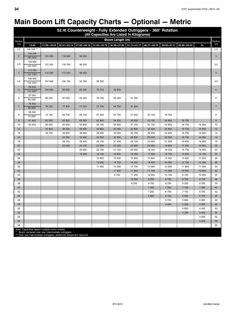
34 5747 (supersedes 5724)-0915-S3
ATC‐3210 Link‐Belt Cranes
Main Boom Lift Capacity Charts - Optional - Metric52.4t Counterweight Fully Extended Outriggers 360° Rotation
(All Capacities Are Listed In Kilograms)
Radius (m)
Boom Length (m)Radius
(m)13.49 17.95-18.24 22.41-23.14 27.02-28.18 31.63-32.79 36.38-37.82 41.13-41.71 46.31-46.75 50.92-51.5 55.96-56.54 61
2.5 185 000 ** 2.5
3136 000
135 950 118 900 96 200 3150 000*
3.5124 850
125 350 118 700 96 200 3.5140 050*
4115 250
116 000 112 050 96 050 4131 750*
4.5106 900
107 800 106 100 92 350 58 500 4.5124 250*
599 550
100 600 99 900 92 350 78 750 29 950 5114 450*
687 000
88 200 87 650 84 450 78 750 59 350 41 450 695 050*
776 850
78 250 77 800 77 200 72 700 54 750 41 450 780 850*
868 650
70 100 69 700 69 150 67 500 54 750 41 400 33 100 18 700 870 000*
9 61 400 63 300 62 900 62 300 62 900 54 200 39 050 33 100 24 900 18 750 9
10 54 450 56 350 56 950 55 850 56 150 50 850 37 100 33 100 24 900 18 750 14 950 10
12 45 900 46 500 46 400 45 800 45 350 33 650 32 000 24 900 18 750 14 950 12
14 38 700 38 900 38 850 38 300 39 050 30 750 28 450 24 900 18 750 14 950 14
16 33 550 33 350 33 550 32 850 28 200 25 500 23 550 18 750 14 950 16
18 28 150 28 400 28 100 27 400 26 150 23 050 21 900 18 450 14 950 18
20 23 250 24 150 23 900 23 350 23 800 20 900 19 900 17 000 14 950 20
22 20 950 20 750 21 100 20 650 19 100 18 250 15 750 14 950 22
24 18 300 18 100 18 650 18 050 17 500 16 750 14 650 14 150 24
26 16 650 16 500 15 900 15 800 15 450 13 650 13 200 26
28 15 050 14 750 14 250 14 500 14 050 12 750 12 300 28
30 11 450 13 250 12 700 12 950 12 550 11 950 11 500 30
32 11 950 11 950 11 700 11 250 10 850 10 800 32
34 9 750 11 050 10 550 10 150 9 750 10 000 34
36 10 050 9 550 9 150 8 750 9 100 36
38 9 200 8 700 8 250 8 200 8 250 38
40 7 900 7 500 7 700 7 500 40
42 7 200 6 750 7 150 6 750 42
44 4 800 6 100 6 450 6 100 44
46 5 700 5 850 5 500 46
48 5 400 5 300 4 950 48
50 4 800 4 450 50
52 4 350 4 000 52
54 3 550 54
56 3 200 56
58 58
Note: Capacities depict multiple boom modes.* Boom centered over rear, intermediate outriggers** Over rear intermediate outriggers, additional equipment required.

355747 (supersedes 5724)-0915-S3
ATC‐3210Link‐Belt Cranes
This information is not for crane operation. Operator must refer to the in-cab information for crane operation. Ratedlifting capacities shown on fully extended outriggers do not exceed 75% of the tipping loads.

36 5747 (supersedes 5724)-0915-S3
ATC‐3210 Link‐Belt Cranes
Manual & Hydraulic Offset Fly Attachment Lift CapacityCharts - Optional - Metric
16.3t Counterweight Fully Extended Outriggers 360° Rotation(All Capacities Are Listed In Kilograms)
Main Boom + 3.7m Offset Fly (Manual Offsets 2°, 15°, 30°, 45° & Hydraulic Offsets 2° 45°)
Radius(m)
Main Boom Length (m)Radius
(m)13.49 17.95-18.24 22.41-23.14 27.02-28.18 31.63-32.79 36.38-37.83 41.13-41.71 46.31-46.75 50.92-51.5 55.96-56.54 61
3 31 600 31 550 31 500 31 450 3
3.5 31 600 31 550 31 500 31 450 3.5
4 31 600 31 550 31 500 31 450 4
4.5 31 600 31 550 31 500 31 450 28 450 27 650 4.5
5 31 600 31 550 31 500 31 450 28 450 27 650 19 500 5
6 31 600 31 550 31 500 31 450 28 450 27 650 25 150 6
7 31 600 31 550 31 500 31 450 28 450 27 650 25 150 24 900 16 150 7
8 31 600 31 550 31 500 30 700 27 200 27 650 25 150 24 900 19 500 8
9 30 400 31 550 29 350 28 600 25 200 26 700 25 150 24 900 19 500 16 050 9
10 29 000 31 550 27 350 26 600 23 450 24 900 25 150 24 900 19 500 16 050 12 750 10
12 25 350 26 650 23 600 23 300 20 550 22 000 23 400 24 450 19 500 16 050 12 750 12
14 19 150 20 350 20 600 20 650 18 350 19 800 20 950 20 250 19 500 16 050 12 750 14
16 16 100 16 800 16 750 16 450 17 050 16 650 15 950 15 950 15 000 12 750 16
18 13 100 13 750 13 700 14 150 14 000 13 900 13 000 13 250 12 750 12 300 18
20 11 450 11 400 11 800 11 650 11 550 10 650 10 950 10 450 10 000 20
22 9 650 9 600 10 000 9 850 9 750 8 850 9 150 8 650 8 150 22
24 8 150 8 500 8 400 8 250 7 450 7 750 7 250 6 800 24
26 6 950 7 400 7 250 7 150 6 200 6 500 6 000 5 550 26
28 6 350 6 200 6 100 5 150 5 450 4 950 4 500 28
30 5 450 5 300 5 200 4 250 4 550 4 050 3 600 30
32 4 700 4 550 4 400 3 500 3 800 3 300 2 850 32
34 3 850 3 750 2 850 3 150 2 600 2 200 34
36 3 300 3 150 2 250 2 550 2 050 1 650 36
38 2 650 1 750 2 050 1 550 1 100 38
40 2 200 1 300 1 600 1 100 40
42 1 200 42
Note: Capacities depict multiple boom modes.
This information is not for crane operation. Operator must refer to the in-cab information for crane operation. Ratedlifting capacities shown on fully extended outriggers do not exceed 75% of the tipping loads.

375747 (supersedes 5724)-0915-S3
ATC‐3210Link‐Belt Cranes
52.4t Counterweight Fully Extended Outriggers 360° Rotation(All Capacities Are Listed In Kilograms)
Main Boom + 3.7m Offset Fly (Manual Offsets 2°, 15°, 30°, 45° & Hydraulic Offsets 2° 45°)
Radius (m)
Main Boom Length (m)Radius
(m)13.49 17.95-18.24 22.41-23.14 27.02-28.18 31.63-32.79 36.38-37.83 41.13-41.71 46.31-46.75 50.92-51.5 55.96-56.54 61
3 31 600 31 550 31 500 31 450 3
3.5 31 600 31 550 31 500 31 450 3.5
4 31 600 31 550 31 500 31 450 4
4.5 31 600 31 550 31 500 31 450 28 450 27 650 4.5
5 31 600 31 550 31 500 31 450 28 450 27 650 19 500 5
6 31 600 31 550 31 500 31 450 28 450 27 650 25 150 6
7 31 600 31 550 31 500 31 450 28 450 27 650 25 150 24 900 16 150 7
8 31 600 31 550 31 500 30 700 27 200 27 650 25 150 24 900 19 500 8
9 30 400 31 550 29 350 28 600 25 200 26 700 25 150 24 900 19 500 16 050 9
10 29 000 31 550 27 350 26 600 23 450 24 900 25 150 24 900 19 500 16 050 12 750 10
12 26 350 30 250 23 600 23 300 20 550 22 000 23 400 24 450 19 500 16 050 12 750 12
14 24 650 27 950 20 600 20 650 18 350 19 800 21 100 22 200 19 500 16 050 12 750 14
16 26 100 18 450 18 450 16 450 17 850 19 200 20 300 19 500 16 050 12 750 16
18 24 200 16 500 16 450 14 850 16 250 17 550 18 650 19 300 16 050 12 750 18
20 14 900 14 850 13 500 14 850 16 150 17 250 17 950 15 850 12 750 20
22 13 600 13 450 12 250 13 650 14 950 16 000 16 750 14 600 12 750 22
24 12 250 11 150 12 600 13 850 14 950 15 700 13 500 12 750 24
26 11 300 10 200 11 650 12 900 13 950 14 650 12 550 12 100 26
28 9 500 10 750 12 050 13 100 13 500 11 650 11 250 28
30 8 750 10 050 11 200 12 350 12 100 10 850 10 450 30
32 8 100 9 350 10 500 11 250 10 800 10 000 9 700 32
34 8 700 9 850 10 150 9 700 9 250 9 100 34
36 8 150 9 250 9 200 8 700 8 250 8 500 36
38 8 700 8 300 7 800 7 450 7 700 38
40 8 150 7 600 7 050 6 850 6 950 40
42 6 850 6 350 6 400 6 200 42
44 6 200 5 700 6 000 5 550 44
46 5 650 5 100 5 400 4 950 46
48 4 550 4 850 4 450 48
50 4 050 4 350 3 950 50
52 2 850 3 900 3 500 52
54 3 500 3 100 54
56 2 700 56
58 2 350 58
Note: Capacities depict multiple boom modes.
This information is not for crane operation. Operator must refer to the in-cab information for crane operation. Ratedlifting capacities shown on fully extended outriggers do not exceed 75% of the tipping loads.

38 5747 (supersedes 5724)-0915-S3
ATC‐3210 Link‐Belt Cranes
Manual Offset Fly Attachment Lift Capacity Charts -Optional - Metric
16.3t Counterweight Fully Extended Outriggers 360° Rotation(All Capacities Are Listed In Kilograms)
61m Main Boom Length
Radius(m)
12.2m Manual Offset Fly 20.4m Manual Offset FlyRadius
(m)2° 15° 30° 45° 2° 15° 30° 45°
12 7 300 12
14 7 300 14
16 7 300 7 300 4 900 16
18 7 300 7 300 4 900 18
20 7 300 7 300 7 200 4 900 4 900 20
22 7 300 7 300 7 200 7 100 4 900 4 900 22
24 7 300 7 300 7 200 7 100 4 900 4 900 24
26 6 050 6 600 7 200 7 100 4 900 4 900 4 900 26
28 4 950 5 450 6 000 6 400 4 900 4 900 4 900 28
30 4 050 4 500 5 000 5 350 4 450 4 900 4 900 4 600 30
32 3 300 3 700 4 150 4 450 3 650 4 400 4 900 4 500 32
34 2 600 3 000 3 400 3 700 2 950 3 650 4 400 4 400 34
36 2 050 2 400 2 750 3 000 2 400 3 000 3 650 4 200 36
38 1 500 1 850 2 150 2 400 1 850 2 450 3 050 3 500 38
40 1 050 1 350 1 650 1 850 1 400 1 900 2 500 2 900 40
42 1 200 1 350 950 1 450 2 000 2 350 42
44 950 1 050 1 550 1 900 44
46 1 100 1 450 46
48 1 050 48
This information is not for crane operation. Operator must refer to the in-cab information for crane operation. Ratedlifting capacities shown on fully extended outriggers do not exceed 75% of the tipping loads.

395747 (supersedes 5724)-0915-S3
ATC‐3210Link‐Belt Cranes
52.4t Counterweight Fully Extended Outriggers 360° Rotation(All Capacities Are Listed In Kilograms)
61m Main Boom Length
Radius(m)
12.2m Manual Offset Fly 20.4m Manual Offset FlyRadius
(m)2° 15° 30° 45° 2° 15° 30° 45°
12 7 300 12
14 7 300 14
16 7 300 7 300 4 900 16
18 7 300 7 300 4 900 18
20 7 300 7 300 7 200 4 900 4 900 20
22 7 300 7 300 7 200 7 100 4 900 4 900 22
24 7 300 7 300 7 200 7 100 4 900 4 900 24
26 7 300 7 300 7 200 7 100 4 900 4 900 4 900 26
28 7 300 7 300 7 200 7 100 4 900 4 900 4 900 28
30 7 300 7 300 7 200 7 100 4 900 4 900 4 900 4 600 30
32 7 300 7 300 7 200 7 100 4 900 4 900 4 900 4 500 32
34 7 300 7 300 7 200 7 100 4 900 4 900 4 900 4 400 34
36 7 300 7 300 7 200 7 100 4 900 4 900 4 900 4 300 36
38 7 300 7 300 7 200 7 100 4 900 4 900 4 750 4 250 38
40 6 850 6 850 6 800 6 800 4 900 4 900 4 650 4 150 40
42 6 400 6 400 6 400 6 400 4 900 4 900 4 550 4 100 42
44 5 900 6 000 6 050 6 050 4 900 4 900 4 450 4 050 44
46 5 300 5 550 5 700 5 700 4 900 4 900 4 350 3 950 46
48 4 750 5 000 5 200 5 300 4 900 4 850 4 250 3 900 48
50 4 300 4 500 4 650 4 750 4 550 4 700 4 150 3 850 50
52 3 800 4 000 4 150 4 250 4 100 4 400 4 050 3 800 52
54 3 400 3 550 3 700 3 750 3 700 4 000 4 000 3 800 54
56 3 000 3 150 3 300 3 350 3 300 3 600 3 850 3 750 56
58 2 650 2 800 2 900 2 950 2 950 3 200 3 450 3 600 58
60 2 350 2 450 2 550 2 600 2 850 3 050 3 200 60
62 2 050 2 150 2 200 2 300 2 500 2 700 2 800 62
64 1 750 1 850 1 900 2 000 2 200 2 400 2 450 64
66 1 500 1 550 1 600 1 750 1 900 2 050 2 100 66
68 1 250 1 300 1 450 1 650 1 750 68
70 1 250 1 400 1 500 70
72 1 000 1 150 1 200 72
74 950 74
This information is not for crane operation. Operator must refer to the in-cab information for crane operation. Ratedlifting capacities shown on fully extended outriggers do not exceed 75% of the tipping loads.

40 5747 (supersedes 5724)-0915-S3
ATC‐3210 Link‐Belt Cranes
52.4t Counterweight Fully Extended Outriggers 360° Rotation(All Capacities Are Listed In Kilograms)
61m Main Boom Length
Radius(m)
28m Manual Offset Fly 35.6m Manual Offset FlyRadius
(m)2° 15° 30° 45° 2° 15° 30° 45°
18 3 700 18
20 3 700 3 050 20
22 3 700 3 700 3 050 22
24 3 700 3 700 3 050 3 000 24
26 3 700 3 700 3 050 3 000 26
28 3 700 3 700 3 650 3 050 3 000 28
30 3 700 3 700 3 650 3 550 3 050 3 000 2 950 30
32 3 700 3 700 3 650 3 550 3 050 3 000 2 950 32
34 3 700 3 700 3 650 3 550 3 050 3 000 2 950 2 850 34
36 3 700 3 700 3 650 3 550 3 050 3 000 2 950 2 850 36
38 3 700 3 700 3 650 3 550 3 050 3 000 2 950 2 850 38
40 3 700 3 700 3 650 3 550 3 050 3 000 2 950 2 850 40
42 3 700 3 700 3 650 3 550 3 050 3 000 2 950 2 850 42
44 3 700 3 700 3 650 3 550 3 050 3 000 2 950 2 800 44
46 3 700 3 700 3 650 3 450 3 050 3 000 2 850 2 700 46
48 3 700 3 700 3 600 3 400 3 050 2 950 2 700 2 600 48
50 3 700 3 700 3 500 3 300 3 050 2 850 2 600 2 500 50
52 3 700 3 700 3 400 3 200 2 950 2 700 2 500 2 400 52
54 3 550 3 650 3 300 3 150 2 800 2 600 2 400 2 300 54
56 3 250 3 400 3 200 3 050 2 650 2 450 2 300 2 200 56
58 2 850 3 150 3 150 3 000 2 550 2 350 2 200 2 100 58
60 2 550 2 850 3 050 2 900 2 400 2 200 2 100 2 000 60
62 2 200 2 500 2 750 2 850 2 100 2 100 2 000 1 950 62
64 1 950 2 200 2 400 2 550 1 850 2 000 1 900 1 850 64
66 1 650 1 900 2 100 2 200 1 550 1 800 1 850 1 800 66
68 1 400 1 600 1 800 1 900 1 300 1 550 1 750 1 700 68
70 1 150 1 350 1 500 1 600 1 050 1 300 1 500 1 600 70
72 950 1 100 1 250 1 300 1 050 1 250 1 300 72
74 1 000 1 000 1 000 1 050 74
This information is not for crane operation. Operator must refer to the in-cab information for crane operation. Ratedlifting capacities shown on fully extended outriggers do not exceed 75% of the tipping loads.

415747 (supersedes 5724)-0915-S3
ATC‐3210Link‐Belt Cranes
Hydraulic Offset Fly Attachment Lift Capacity Charts -Optional - Metric
16.3t Counterweight Fully Extended Outriggers 360° Rotation(All Capacities Are Listed In Kilograms)
61m Main Boom Length
Radius(m)
12.2m Hydraulic Offset Fly 20.4m Hydraulic Offset FlyRadius
(m)2° 15° 15° 30° 30° 45° 2° 15° 15° 30° 30° 45°
12 7 300 12
14 7 250 7 250 14
16 7 250 7 250 4 900 16
18 7 250 7 000 7 200 4 900 4 900 18
20 7 250 7 200 7 200 4 900 4 900 20
22 7 250 7 200 7 100 4 900 4 900 22
24 7 250 7 200 7 100 4 900 4 850 4 850 24
26 6 050 6 600 7 100 4 900 4 850 4 800 26
28 4 950 5 450 6 000 4 900 4 850 4 700 28
30 4 050 4 500 5 000 4 450 4 850 4 600 30
32 3 300 3 700 4 150 3 650 4 400 4 500 32
34 2 600 3 000 3 400 2 950 3 650 4 400 34
36 2 050 2 400 2 750 2 400 3 000 3 650 36
38 1 500 1 850 2 150 1 850 2 450 3 050 38
40 1 050 1 350 1 650 1 400 1 900 2 500 40
42 1 200 950 1 450 2 000 42
44 1 050 1 550 44
46 1 100 46
This information is not for crane operation. Operator must refer to the in-cab information for crane operation. Ratedlifting capacities shown on fully extended outriggers do not exceed 75% of the tipping loads.
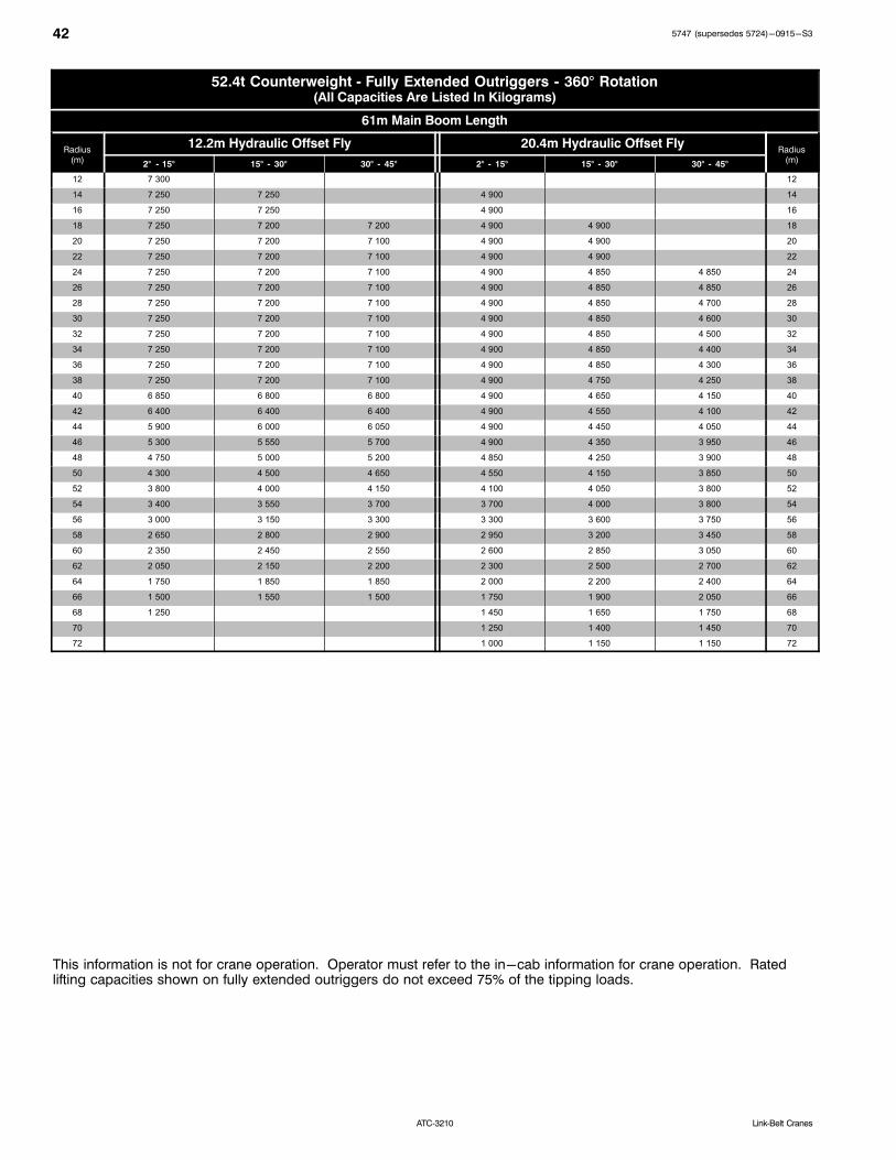
42 5747 (supersedes 5724)-0915-S3
ATC‐3210 Link‐Belt Cranes
52.4t Counterweight Fully Extended Outriggers 360° Rotation(All Capacities Are Listed In Kilograms)
61m Main Boom Length
Radius(m)
12.2m Hydraulic Offset Fly 20.4m Hydraulic Offset FlyRadius
(m)2° 15° 15° 30° 30° 45° 2° 15° 15° 30° 30° 45°
12 7 300 12
14 7 250 7 250 4 900 14
16 7 250 7 250 4 900 16
18 7 250 7 200 7 200 4 900 4 900 18
20 7 250 7 200 7 100 4 900 4 900 20
22 7 250 7 200 7 100 4 900 4 900 22
24 7 250 7 200 7 100 4 900 4 850 4 850 24
26 7 250 7 200 7 100 4 900 4 850 4 850 26
28 7 250 7 200 7 100 4 900 4 850 4 700 28
30 7 250 7 200 7 100 4 900 4 850 4 600 30
32 7 250 7 200 7 100 4 900 4 850 4 500 32
34 7 250 7 200 7 100 4 900 4 850 4 400 34
36 7 250 7 200 7 100 4 900 4 850 4 300 36
38 7 250 7 200 7 100 4 900 4 750 4 250 38
40 6 850 6 800 6 800 4 900 4 650 4 150 40
42 6 400 6 400 6 400 4 900 4 550 4 100 42
44 5 900 6 000 6 050 4 900 4 450 4 050 44
46 5 300 5 550 5 700 4 900 4 350 3 950 46
48 4 750 5 000 5 200 4 850 4 250 3 900 48
50 4 300 4 500 4 650 4 550 4 150 3 850 50
52 3 800 4 000 4 150 4 100 4 050 3 800 52
54 3 400 3 550 3 700 3 700 4 000 3 800 54
56 3 000 3 150 3 300 3 300 3 600 3 750 56
58 2 650 2 800 2 900 2 950 3 200 3 450 58
60 2 350 2 450 2 550 2 600 2 850 3 050 60
62 2 050 2 150 2 200 2 300 2 500 2 700 62
64 1 750 1 850 1 850 2 000 2 200 2 400 64
66 1 500 1 550 1 500 1 750 1 900 2 050 66
68 1 250 1 450 1 650 1 750 68
70 1 250 1 400 1 450 70
72 1 000 1 150 1 150 72
This information is not for crane operation. Operator must refer to the in-cab information for crane operation. Ratedlifting capacities shown on fully extended outriggers do not exceed 75% of the tipping loads.
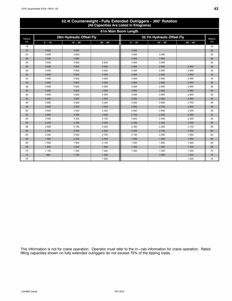
435747 (supersedes 5724)-0915-S3
ATC‐3210Link‐Belt Cranes
52.4t Counterweight Fully Extended Outriggers 360° Rotation(All Capacities Are Listed In Kilograms)
61m Main Boom Length
Radius(m)
28m Hydraulic Offset Fly 35.7m Hydraulic Offset FlyRadius
(m)2° 15° 15° 30° 30° 45° 2° 15° 15° 30° 30° 45°
18 18
20 3 650 3 650 3 050 20
22 3 650 3 650 3 000 3 000 22
24 3 650 3 650 3 000 3 000 24
26 3 650 3 600 3 600 3 000 3 000 26
28 3 650 3 600 3 600 3 000 2 900 2 900 28
30 3 650 3 600 3 550 3 000 2 900 2 900 30
32 3 650 3 600 3 550 3 000 2 900 2 850 32
34 3 650 3 600 3 550 3 000 2 900 2 850 34
36 3 650 3 600 3 550 3 000 2 900 2 850 36
38 3 650 3 600 3 550 3 000 2 900 2 850 38
40 3 650 3 600 3 550 3 000 2 900 2 850 40
42 3 650 3 600 3 550 3 000 2 900 2 850 42
44 3 650 3 600 3 550 3 000 2 900 2 800 44
46 3 650 3 600 3 450 3 000 2 850 2 700 46
48 3 650 3 600 3 400 2 950 2 700 2 600 48
50 3 650 3 500 3 300 2 850 2 600 2 500 50
52 3 650 3 400 3 200 2 700 2 500 2 400 52
54 3 550 3 300 3 150 2 600 2 400 2 300 54
56 3 250 3 200 3 050 2 450 2 300 2 200 56
58 2 850 3 150 3 000 2 350 2 200 2 100 58
60 2 550 2 850 2 900 2 200 2 100 2 000 60
62 2 200 2 500 2 750 2 100 2 000 1 950 62
64 1 950 2 200 2 400 1 850 1 900 1 850 64
66 1 650 1 900 2 100 1 550 1 800 1 800 66
68 1 400 1 600 1 800 1 300 1 550 1 700 68
70 1 150 1 350 1 500 1 050 1 300 1 500 70
72 950 1 100 1 250 1 050 1 250 72
74 1 000 1 000 74
This information is not for crane operation. Operator must refer to the in-cab information for crane operation. Ratedlifting capacities shown on fully extended outriggers do not exceed 75% of the tipping loads.

44 5747 (supersedes 5724)-0915-S3
ATC‐3210 Link‐Belt Cranes
This Page Intentionally Blank
5747 (supersedes 5724)-0915-S3
ATC‐3210 Link‐Belt Cranes
Link-Belt Construction Equipment Company Lexington, Kentucky www.linkbelt.com�Link-Belt is a registered trademark. Copyright 2015. We are constantly improving our products and therefore reserve the right to change designs and specifications.