technical data - daikintech.co.uk€¦ · 2-1 technical specifications fcq35c8veb fcq50c8veb...
TRANSCRIPT

Indoor Units
FCQ-C8VEB
air conditioning systems
technical data
Indoor Units
FCQ-C8VEB
air conditioning systems
technical data

• Split Sky Air • Indoor Units 1
• Indoor Units • R-410A • FCQ-C8VEB
TABLE OF CONTENTSFCQ-C8VEB
1 Features . . . . . . . . . . . . . . . . . . . . . . . . . . . . . . . . . . . . . . . . . . . . . . . . . . . . . . . . . . . . . 2
2 Specifications . . . . . . . . . . . . . . . . . . . . . . . . . . . . . . . . . . . . . . . . . . . . . . . . . . . . . . . 3
Technical Specifications . . . . . . . . . . . . . . . . . . . . . . . . . . . . . . . . . . . . . . . . . . . . . 3
Electrical Specifications (50Hz) . . . . . . . . . . . . . . . . . . . . . . . . . . . . . . . . . . . . . . 4
Electrical Specifications (60Hz) . . . . . . . . . . . . . . . . . . . . . . . . . . . . . . . . . . . . . . 4
3 Safety device settings . . . . . . . . . . . . . . . . . . . . . . . . . . . . . . . . . . . . . . . . . . . . . 5
4 Options . . . . . . . . . . . . . . . . . . . . . . . . . . . . . . . . . . . . . . . . . . . . . . . . . . . . . . . . . . . . . . 6
5 Dimensional drawing & centre of gravity . . . . . . . . . . . . . . . . . . . . . . . . 7
Dimensional drawing for standard panel . . . . . . . . . . . . . . . . . . . . . . . . . . . . . 7
Dimensional drawing for auto cleaning panel . . . . . . . . . . . . . . . . . . . . . . . . 8
Dimensional drawing with accessories . . . . . . . . . . . . . . . . . . . . . . . . . . . . . . . 9
Centre of gravity . . . . . . . . . . . . . . . . . . . . . . . . . . . . . . . . . . . . . . . . . . . . . . . . . . . . 10
6 Piping diagram. . . . . . . . . . . . . . . . . . . . . . . . . . . . . . . . . . . . . . . . . . . . . . . . . . . . . 12
7 Wiring diagram. . . . . . . . . . . . . . . . . . . . . . . . . . . . . . . . . . . . . . . . . . . . . . . . . . . . . 13
Wiring diagram . . . . . . . . . . . . . . . . . . . . . . . . . . . . . . . . . . . . . . . . . . . . . . . . . . . . . . 13
8 Sound data . . . . . . . . . . . . . . . . . . . . . . . . . . . . . . . . . . . . . . . . . . . . . . . . . . . . . . . . . 14
Sound pressure spectrum . . . . . . . . . . . . . . . . . . . . . . . . . . . . . . . . . . . . . . . . . . . 14
Sound power spectrum . . . . . . . . . . . . . . . . . . . . . . . . . . . . . . . . . . . . . . . . . . . . . 16
9 Air flow pattern. . . . . . . . . . . . . . . . . . . . . . . . . . . . . . . . . . . . . . . . . . . . . . . . . . . . . 18
!

• Indoor Units • R-410A • FCQ-C8VEB
• Split Sky Air • Indoor Units2
1 Features
Indoor Unit Split Sky FCQ-C8VEB R-410A • 360° air discharge ensures uniform air flow and temperature distribution
• Modern style decoration panel is available in 3 different variations: Standard panel in white (RAL9010) with grey louvers and standard panel in full white (RAL9010) including white louvers, auto cleaning panel
• For auto cleaning panel:
- Daikin introduces first auto cleaning cassette to European market1- Higher efficiency and comfort from daily auto cleaning of the filter1
- Lower maintenance costs thanks to auto cleaning function1
- Easy removal of dust with a vacuum cleaner without opening the unit1
• Fresh air intake: up to 20 % (optional kit required)
• Comfortable horizontal air discharge ensures draughtfree operation and prevents ceiling soiling
• 23 different air flow patterns possible
• Drain-up pump with 850 mm lift fitted as standard
1 Only for auto cleaning panel BYCQ140CG
Heat Pump
2 steps Optional Optional Optional

• Split Sky Air • Indoor Units 3
• Indoor Units • R-410A • FCQ-C8VEB
2 Specifications
2-1 Technical Specifications FCQ35C8VEB FCQ50C8VEB FCQ60C8VEB FCQ71C8VEB FCQ100C8VEB FCQ125C8VEB FCQ140C8VEB
Power input 50Hz Cooling Nom. kW 0.056 0.120
Heating Nom. kW 0.056 0.120
Casing Material Galvanised steel plate
Dimensions Unit Height mm 204 246
Width mm 840
Depth mm 840
Packed unit Height mm 220 262
Width mm 882
Depth mm 882
Weight Unit kg 19 21 23
Packed Unit kg 24 25 28
Heat Exchanger Dimensions Length mm inside: 2096, outside: 2152
Nr of Rows 2
Fin Pitch mm 1.2
Nr of Passes 4 6 7 9
Face Area m² 0.267 0.357 0.446
Nr of Stages 6 8 10
Empty Tubeplate Hole 4 0
Fin Type Cross fin coil (Multi louver fins and Hi-XSS tubes)
Fan Type Turbo fan
Quantity 1
Air Flow Rate Cooling High m³/min 10.5 12.5 13.5 15.5 23.5 27.5
Low m³/min 8.5 9.0 16.0 19.0
Heating High m³/min 12.5 13.5 16.0 23.5 27.5
Low m³/min 10.0 8.5 9.5 16.0 19.0
Fan Motor Model QTS48D11M QTS48C15M
Number of steps 2
Output (high) W 56 120
Cooling Sound Power High dBA 49 51 54 58
Sound Pressure High dBA 31 33 37 41
Low dBA 27 28 32 35
Heating Sound Pressure High dBA 31 33 34 37 41 42
Low dBA 27 28 32 35
Sound Level Sound Absorbing Insulation Foamed polyurethane
Refrigerant Type R-410A
Piping connections Liquid (OD) Type Flare connection
Diameter (OD) mm 6.35 9.52
Gas Type Flare connection
Diameter (OD) mm 9.52 12.7 15.9
Drain Diameter (OD) mm VP25 (O.D. 32 / I.D. 25)
Heat Insulation Foamed polystyrene/polyethylene

• Indoor Units • R-410A • FCQ-C8VEB
• Split Sky Air • Indoor Units4
2 Specifications
Decoration Panel Model BYCQ140CW1
Colour Pure White (RAL 9010)
Dimensions H mm 50
W mm 950
D mm 950
Weight kg 5.5
Model BYCQ140CW1W
Colour Pure White (RAL 9010)
Dimensions H mm 50
W mm 950
D mm 950
Weight kg 5.5
Model BYCQ140CGW1
Colour Pure White (RAL 9010)
Dimensions H mm 130
W mm 950
D mm 950
Weight kg 5.5
Air Filter Resin net with mold resistance
Standard Accessories Item Installation and operation manual
Drain hose
Clamp for drain hose
Washer for hanger bracket
Screws
Installation guide
Insulation for fitting
Sealing pads
Drain sealing pad
2-2 Electrical Specifications (50Hz) FCQ35C8VEB FCQ50C8VEB FCQ60C8VEB FCQ71C8VEB FCQ100C8VEB FCQ125C8VEB FCQ140C8VEB
Power Supply Phase 1~
Frequency Hz 50
Voltage V 220-440
Voltage range Min. % -10
Voltage range Max. % 10
Current Minimum circuit amps (MCA) A 9.75 19.75 17.0 24.7 25.0
Maximum fuse amps (MFA) A 10 20 32
2-3 Electrical Specifications (60Hz) FCQ35C8VEB FCQ50C8VEB FCQ60C8VEB FCQ71C8VEB FCQ100C8VEB FCQ125C8VEB FCQ140C8VEB
Power Supply Phase 1~
Frequency Hz 60
Voltage V 220
Voltage range Min. % -10
Voltage range Max. % 10
2-1 Technical Specifications FCQ35C8VEB FCQ50C8VEB FCQ60C8VEB FCQ71C8VEB FCQ100C8VEB FCQ125C8VEB FCQ140C8VEB

• Split Sky Air • Indoor Units 5
• Indoor Units • R-410A • FCQ-C8VEB
3 Safety device settings
Safety devices 35 50 60 71 100 125 140
FCQ
PC board fuse 250V 5A 250V 5A 250V 5A 250V 5A 250V 5A 250V 5A 250V 5A
Fan motor thermal fuse °C --- --- --- --- --- --- ---
Fan motor thermal protector °COff: 108 ±5
(On: 96 ±15)
Off: 108 ±5
(On: 96 ±15)
Off: 108 ±5
(On: 96 ±15)
Off: 108 ±5
(On: 96 ±15)
Off: 108 ±5
(On: 96 ±15)
Off: 108 ±5
(On: 96 ±15)
Off: 108 ±5
(On: 96 ±15)
Drain pump fuse °C 145 145 145 145 145 145 145
3TW28921-3
FCQ35-140C8
• Indoor Units • R-410A • FCQ-C8VEB
• Split Sky Air • Indoor Units6
4 Options
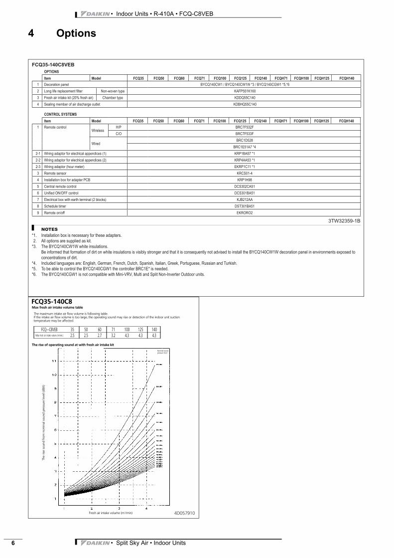
FCQ35-140C8VEB
3TW32359-1B
NOTES
*1. Installation box is necessary for these adapters.
*2. All options are supplied as kit.
*3. The BYCQ140CW1W white insulations.
Be informed that formation of dirt on white insulations is visibly stronger and that it is consequently not advised to install the BYCQ140CW1W decoration panel in environments exposed to
concentrations of dirt.
*4. Included languages are: English, German, French, Dutch, Spanish, Italian, Greek, Portuguese, Russian and Turkish.
*5. To be able to control the BYCQ140CGW1 the controller BRC1E* is needed.
*6. The BYCQ140CGW1 is not compatible with Mini-VRV, Multi and Split Non-Inverter Outdoor units.
OPTIONS
Item Model FCQ35 FCQ50 FCQ60 FCQ71 FCQ100 FCQ125 FCQ140 FCQH71 FCQH100 FCQH125 FCQH140
1 Decoration panel BYCQ140CW1 / BYCQ140CW1W *3 / BYCQ140CGW1 *5,*6
2 Long life replacement fi lter Non-woven type KAFP551K160
3 Fresh air intake kit (20% fresh air) Chamber type KDDQ55C140
4 Sealing member of air discharge outlet KDBHQ55C140
CONTROL SYSTEMS
Item Model FCQ35 FCQ50 FCQ60 FCQ71 FCQ100 FCQ125 FCQ140 FCQH71 FCQH100 FCQH125 FCQH140
1 Remote controlWireless
H/P BRC7F532F
C/O BRC7F533F
WiredBRC1D528
BRC1E51A7 *4
2-1 Wiring adaptor for electrical appendices (1) KRP1BA57 *1
2-2 Wiring adaptor for electrical appendices (2) KRP4AA53 *1
2-3 Wiring adaptor (hour meter) EKRP1C11 *1
3 Remote sensor KRCS01-4
4 Installation box for adapter PCB KRP1H98
5 Central remote control DCS302CA51
6 Unifi ed ON/OFF control DCS301BA51
7 Electrical box with earth terminal (2 blocks) KJB212AA
8 Schedule timer DST301BA51
9 Remote on/off EKRORO2
4D057910
FCQ35-140C8
The rise of operating sound at with fresh air intake kit
Max fresh air intake volume table
FCQ∼C VEB 35 50 60 71 100 125 140Max fresh air intake volume (m/min.) 2.5 2.5 2.7 3.2 4.3 4.3 4.3
Fresh air intake volume (m`/min)
The
rise
soun
dfro
mno
min
also
und
pres
sure
leve
l(dB
A)
The maximum intake air flow volume is following table.If the intake air flow volume is too large, the operating sound may rise or detection of the indoor unit suctiontemperature may be affected.
Nominal soundpressure level
8
• Split Sky Air • Indoor Units 7
• Indoor Units • R-410A • FCQ-C8VEB
5 Dimensional drawing & centre of gravity
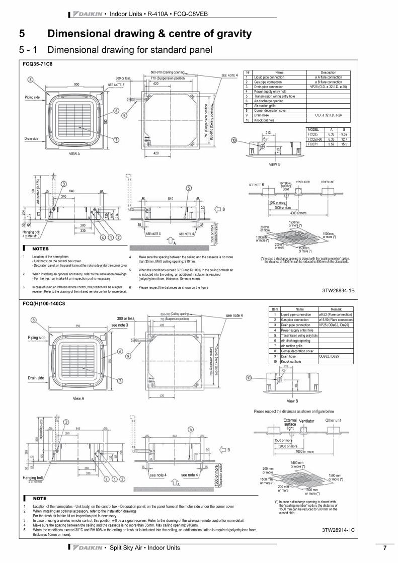
5 - 1 Dimensional drawing for standard panelFCQ35-71C8
3TW28834-1B
Nr Name Description
1 Liquid pipe connection ø A flare connection
2 Gas pipe connection ø B flare connection
3 Drain pipe connection VP25 (O.D. ø 32 /I.D. ø 25)
4 Power supply entry hole
5 Transmission wiring entry hole
6 Air discharge opening
7 Air suction grille
8 Corner decoration cover
9 Drain hose O.D. ø 32 /I.D. ø 26
10 Knock out hole
Piping side
Drain side
SEE NOTE 3
300 or less
860-910 (Ceiling opening)
710 (Suspension position
950 420
420
780
(Sus
pens
ion
posi
tion
860-
910
(Cei
ling
open
ing)
SEE NOTE 4
175
850
Adj
usta
ble
(0-6
75)
125
55 840
340
280
330
165
214
55
55 55
35
SEE NOTE 4 SEE NOTE 4
84013
0
35
1500
or
mor
e(in
stal
latio
n sp
ace)
1500 or more
2000 or more
4000 or more
EXTERNALSURFACE
LIGHT
VENTILATOR OTHER UNIT
1500mm or more (*)
1500mm or more (*)
1500mm or more (*)
200mm or more
1500mm or more (*)
200mm or more
(*) In case a discharge opening is closed with the ‘sealing member’ option, the distance of 1500mm can be reduced to 500mm on the closed side.
Hanging bolt4 x M8~M10
MODEL A B
FCQ35 6.35 9.52
FCQ50-60 6.35 12.7
FCQ71 9.52 15.9
213
139
75
VIEW B
VIEW A
SEE NOTE 6
950
5020
4
4010
NOTES
1 Location of the nameplates- Unit body: on the control box cover.
- Decoration panel: on the panel frame at the motor side under the corner cover
2 When installing an optional accessory, refer to the installation drawings.
- For the fresh air intake kit an inspection port is necessary
3 In case of using an infrared remote control, this position will be a signal
receiver. Refer to the drawing of the infrared remote control for more detail.
4 Make sure the spacing between the ceiling and the cassette is no more
than 35mm. MAX ceiling opening: 910mm.
5 When the conditions exceed 30°C and RH 80% in the ceiling or fresh air
is inducted into the ceiling, an additional insulation is required (polyethylene foam, thickness 10mm or more).
6 Please respect the distances as shown on the figure
FCQ(H)100-140C8
3TW28914-1C
Piping side
Drain side
see note 3
see note 4300 or less
(Ceiling opening)
(Suspension position)
(Sus
pens
ion
posi
tion)
(Cei
ling
open
ing)
Please respect the distances as shown on figure below
Other unitVentilatorExternal surface
light
1500 or more
2000 or more
4000 or more
1500 mm or more (*)
1500 mm or more (*)
1500 mm or more (*)1500 mm
or more (*)
200 mm or more
200 mm or more
(*) In case a discharge opening is closed with the “sealing member” option, the distance of 1500 mm can be reduced to 500 mm on the closed side.
see note 4see note 4Hanging bolt
adju
stab
le
1500
or
mor
e (S
uspe
nsio
n po
sitio
n)
View AView B
Item Name Remark
1 Liquid pipe connection ø9.52 (Flare connection)
2 Gas pipe connection ø15.90 (Flare connection)
3 Drain pipe connection VP25 (ODø32, IDø25)
4 Power supply entry hole
5 Transmission wiring entry hole
6 Air discharge opening
7 Air suction grille
8 Corner decoration cover
9 Drain hose ODø32, IDø25
10 Knock out hole
NOTE
1 Location of the nameplates - Unit body: on the control box - Decoration panel: on the panel frame at the motor side under the corner cover2 When installing an optional accessory, refer to the installation drawings
For the fresh air intake kit an inspection port is necessary3 In case of using a wireles remote control, this position will be a signal receiver. Refer to the drawing of the wireless remote control for more detail.4 Make sure the spacing between the ceiling and the cassette is no more than 35mm. Max cailing opening: 910mm.5 When the conditions exceed 30°C and RH 80% in the ceiling or fresh air is inducted into the ceiling, an additionalinsulation is required (polyethylene foam,
thickness 10mm or more).
• Indoor Units • R-410A • FCQ-C8VEB
• Split Sky Air • Indoor Units8
5 Dimensional drawing & centre of gravity
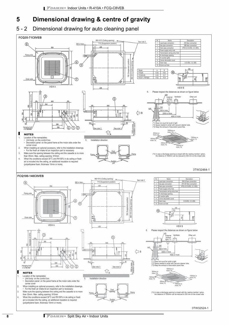
5 - 2 Dimensional drawing for auto cleaning panel
FCQ100-140C8VEB
3TW32524-1
NOTES
Location of the nameplates:Unit body: on the control box.Decoration panel: on the panel frame at the motor side under the corner cover
When installing an optional accessory, refer to the installation drawings.For the fresh air intake kit an inspection part is necessary
Make sure the spacing between the ceiling and the cassette is no more
than 35mm. Max. ceiling opening: 910mm
When the conditions exceed 30°C and RH 80% in de ceiling or fresh
air is included into the ceiling, an additional insulation is required
(polyethylene foam, thickness 10mm or more).
1.••
2.•
3.
4.
Nr Name Description
1 Liquid pipe connection Ø9.52 fl are connection
2 Gas pipe connection Ø15.90 fl are connection
3 Drain pipe connection VP25 (O.D.Ø32, I.D. Ø25)
4 Power supply entry hole
5 Transmission wiring entry hole
6 Air discharge opening
7 Air suction grille
8 Corner decoration cover
9 Drain hose O.D.Ø32, I.D. Ø26
10 Knock out hole
Piping side
Drain side
VIEW A
Hanging bolt
Adj
usta
ble
(0~
675)
710 (Suspension position)300 or less
860~910 (Ceiling opening)
780
(Sus
pens
ion
posi
tion)
860~
910
(Cei
ling
open
ing)
See note 3
See note 3 See note 3
1500
or
mor
e(In
stal
latio
n sp
ace)
VIEW B
Please respect the distances as shown on fi gure below6.
Installation direction5.
Piping Piping
Dustopening
Suctiongrill
Externalsurfacelight (*1)
Ventilator Other unit
256
1500 or more
2000 or more
4000 or more
(*1) Does not count for build in light(*2) Space needed to enter with vacuum-cleaner tube.(*3) Keep the exhaust of decoration panel free.
1500mm or more (*4)
200mm or more (*4)
1500mm or more (*4)
200mm or more (*4) 1500mm or
more (*4)
1500mm or more (*4)
(*4) In case a discharge opening is closed with the ‘sealing member’ option, the distance of 1500mm can be reduced to 500 mm on the closed side.

• Split Sky Air • Indoor Units 9
• Indoor Units • R-410A • FCQ-C8VEB
5 Dimensional drawing & centre of gravity
5 - 3 Dimensional drawing with accessoriesFCQ35,50,60,71C8
3D057035
Nr Name Description
1 Indoor unit
2 Decoration panel
3 Suction chamber
4 Connecting chamber (Right)
5 Connecting chamber (Left)
NOTES
1 When installing this kit, inspection hatch is necessary.(It is necessary when servicing.) Either one of inspection hatches must be installed.
2 Field construction.3 The corner air outlet of this part must be shut.4 In case of mounting a duct fan, make sure to use a wiring adapter for
electrical appendices and link with the indoor unit fan.
1 The intake air flow rate is recommended to be 20%or less of the H speed air flow rate.If the intake air flow rate is too large, the operatingsound may rise or detection of the indoor unit suction temperature may be affected.
2 It indicates the distance between the T-tube inlet and theindoor unit inlet when the T-tube is connected.
Ventilation resistance in chamber (note 6)Service acces panel:
450 x 450 mm or more
(Refer to note 1)
Service acces panel:
450 x 450 mm or more
(Refer to note 1)Installation service access panel
note 3
note 3
Pipe connection side
Drain connection side
View A 455 (Ceiling opening panel)
Connecting chamber mounting space
T-tube
Field supplyAir flow rate (m3/min)
Sta
tic p
ress
ure
of c
ham
ber (
Pa)
Inlet
(*) In case a discharge opening is closed with the ‘sealing member’ option, the distance of 1500 mm can be reduced to 500 mm on the closed side
FCQ100,125,140C8
3D057034
A
Nr Name Description
1 Indoor unit
2 Decoration panel
3 Suction chamber
4 Connecting chamber (Right)
5 Connecting chamber (Left)
NOTES
1 When installing this kit, inspection hatch is necessary.(It is necessary when servicing.) Either one of inspection hatches must be installed.
2 Field construction.3 The corner air outlet of this part must be shut.4 In case of mounting a duct fan, make sure to use a wiring adapter for
electrical appendices and link with the indoor unit fan.
1 The intake air flow rate is recommended to be 20%or less of the H speed air flow rate.If the intake air flow rate is too large, the operatingsound may rise or detection of the indoor unit suction temperature may be affected.
2 It indicates the distance between the T-tube inlet and theindoor unit inlet when the T-tube is connected.
Ventilation resistance in chamber (note 6)Service acces panel:
450 x 450 mm or more
(Refer to note 1)
Service acces panel:
450 x 450 mm or more
(Refer to note 1)Installation service access panel
note 3
note 3
Pipe connection side
Drain connection side
View A 455 (Ceiling opening panel)
Connecting chamber mounting space
T-tube
Field supplyAir flow rate (m3/min)
Sta
tic p
ress
ure
of c
ham
ber (
Pa)
Inlet
306
(*) In case a discharge opening is closed with the ‘sealing member’ option, the distance of 1500 mm can be reduced to 500 mm on the closed side.
• Indoor Units • R-410A • FCQ-C8VEB
• Split Sky Air • Indoor Units10
5 Dimensional drawing & centre of gravity
5 - 4 Centre of gravityFCQ35-140C8
3D056851
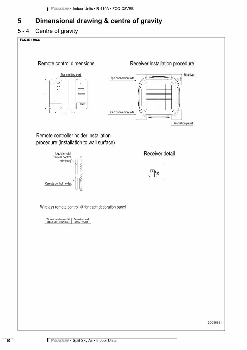
Transmitting part
Remote control dimensions
Pipe connection side
Drain connection side
Receiver installation procedure
Receiver
Decoration panel
Remote controller holder installation
procedure (installation to wall surface)
Receiver detail
Wireless remote control kit for each decoration panel
Wireless remote control kit Decoration panelBRC7F532F BRC7F533F BYCQ140CW1
Liquid crystalremote control
(wireless)
Remote control holder
• Split Sky Air • Indoor Units 11
• Indoor Units • R-410A • FCQ-C8VEB
5 Dimensional drawing & centre of gravity
5 - 4 Centre of gravity
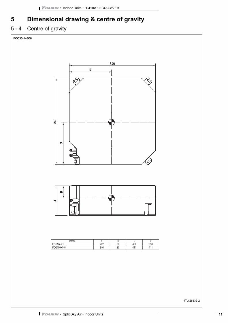
FCQ35-140C8
4TW28839-2
Models A B C DFCQ35~71 202 60 409 358FCQ100~140 246 90 411 411

• Indoor Units • R-410A • FCQ-C8VEB
• Split Sky Air • Indoor Units12
6 Piping diagram
FCQ35-140C8
3TW28925-1A
Heat exchanger
Fan Liquid pipe connection port
Gas pipe connection port
Refrigerant flow
CoolingHeating
Model Gas LiquidFCQ35C8 Ø9.52 Ø6.35FCQ50C8
Ø12.70 Ø6.35FCQ60C8FCQ71C8
Ø15.90 Ø9.52FCQ100C8FCQ125C8FCQ140C8
Refrigerant pipe connection port diameters
• Split Sky Air • Indoor Units 13
• Indoor Units • R-410A • FCQ-C8VEB
7 Wiring diagram
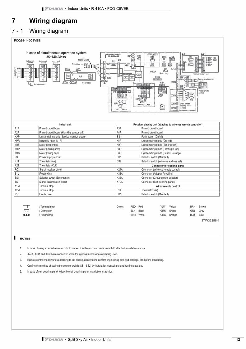
7 - 1 Wiring diagramFCQ35-140C8VEB
3TW32356-1
NOTES
In case of using a central remote control, connect it to the unit in accordance with th attached installation manual.
X24A, X33A and X335A are connected when the optional accessories are being used.
Remote control model varies according to the combination system, confi rm engineering data and catalogs, etc. before connecting.
Confi rm the method of setting the selector switch (SS1, SS2) by installation manual and engineering data, etc.
In case of self cleaning panel follow the self cleaning panel installation instruction.
1.
2.
3.
4.
5.
Indoor unit(master)
Indoor unit Receiver display unit (attached to wireless remote controller)
A1P Printed circuit board A3P Printed circuit board
A2P Printed circuit board (Humidity sensor unit) A4P Printed circuit board
HAP Light emitting diode (Service monitor green) BS1 Push button (On/off)
KPR Magnetic relay (M1P) H1P Light emitting diode (On-red)
M1F Motor (Indoor fan) H2P Light emitting diode (Timer-green)
M1P Motor (Drain pump) H3P Light emitting diode (Filter sign-red)
M1S Motor (Swing fl ap) H4P Light emitting diode (Defrost - orange)
PS Power supply circuit SS1 Selector switch (Main/sub)
R1T Thermistor (Air) SS2 Selector switch (Wireless address set)
R2T Thermistor (Coil) Connector for optional parts
RC Signal receiver circuit X24A Connector (Wireless remote control)
S1L Float switch X33A Connector (Adapter for wiring)
SS1 Selector switch (Emergency) X35A Connector (Group control adapter)
TC Signal transmission circuit X70A Connector (Self cleaning panel)
X1M Terminal strip Wired remote control
X2M Terminal strip R1T Thermistor (Air)
Z1C Ferrite core SS1 Selector switch (Main/sub)
: Terminal strip Colors: RED Red YLW Yellow BRN Brown
: Connector BLK Black GRN Green GRY Grey
: Field wiring WHT White ORG Orange BLU Blue
Indoor unit(slave)
Remote control
To o
utdo
or u
nit
Control box
To outdoor unit
Norm. emg. Receiver display unit
Central remote control (note1)
Wired remote control
indoor
Exept for self cleaning panel (note 5)
Indoor unit(slave)
35~60 CLASS35~60 CLASS
In case of simultaneous operation system
35~140-Class
35~71 CLASS
100~140 CLASS
• Indoor Units • R-410A • FCQ-C8VEB
• Split Sky Air • Indoor Units14
8 Sound data
8 - 1 Sound pressure spectrum
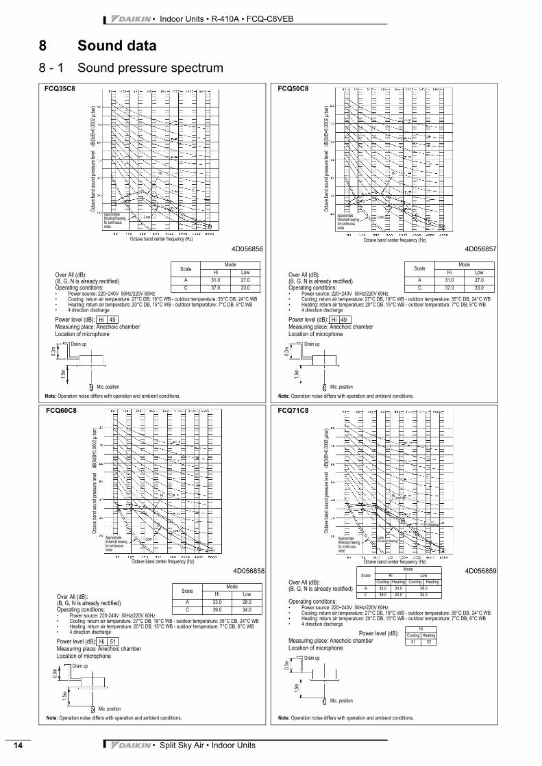
4D056856
NOTES
Over All (dB):(B, G, N is already rectified)Operating conditons:• Power source: 220~240V 50Hz/220V 60Hz• Cooling: return air temperature: 27°C DB, 19°C WB - outdoor temperature: 35°C DB, 24°C WB• Heating: return air temperature: 20°C DB, 15°C WB - outdoor temperature: 7°C DB, 6°C WB• 4 direction discharge
Power level (dB): Measuring place: Anechoic chamberLocation of microphone
Oct
ave
band
sou
nd p
ress
ure
leve
l d
B(0
dB=0
.000
2 μ
bar
)
Approximate threshold hearing for continuous noise
FCQ35C8
Octave band center frequency (Hz)
Low
Hi
ScaleMode
Hi Low
A 31.0 27.0
C 37.0 33.0
Drain up
Mic. position
1.5m
0.3m
Hi 49
Note: Operation noise differs with operation and ambient conditions.
4D056857
NOTES
Over All (dB):(B, G, N is already rectified)Operating conditons:• Power source: 220~240V 50Hz/220V 60Hz• Cooling: return air temperature: 27°C DB, 19°C WB - outdoor temperature: 35°C DB, 24°C WB• Heating: return air temperature: 20°C DB, 15°C WB - outdoor temperature: 7°C DB, 6°C WB• 4 direction discharge
Power level (dB): Measuring place: Anechoic chamberLocation of microphone
Oct
ave
band
sou
nd p
ress
ure
leve
l d
B(0
dB=0
.000
2 μ
bar
)
Approximate threshold hearing for continuous noise
FCQ50C8
Octave band center frequency (Hz)
Low
Hi
ScaleMode
Hi Low
A 31.0 27.0
C 37.0 33.0
Drain up
Mic. position
1.5m
0.3m
Hi 49
Note: Operation noise differs with operation and ambient conditions.
4D056858
NOTES
Over All (dB):(B, G, N is already rectified)Operating conditons:• Power source: 220-240V 50Hz/220V 60Hz• Cooling: return air temperature: 27°C DB, 19°C WB - outdoor temperature: 35°C DB, 24°C WB• Heating: return air temperature: 20°C DB, 15°C WB - outdoor temperature: 7°C DB, 6°C WB• 4 direction discharge
Power level (dB): Measuring place: Anechoic chamberLocation of microphone
Oct
ave
band
sou
nd p
ress
ure
leve
l d
B(0
dB=0
.000
2 μ
bar
)
Approximate threshold hearing for continuous noise
FCQ60C8
Octave band center frequency (Hz)
Low
Hi
ScaleMode
Hi Low
A 33.0 28.0
C 39.0 34.0
Drain up
Mic. position
1.5m
0.3m
Hi 51
Note: Operation noise differs with operation and ambient conditions.
4D056859
Over All (dB):(B, G, N is already rectified)
Operating conditons:• Power source: 220~240V 50Hz/220V 60Hz• Cooling: return air temperature: 27°C DB, 19°C WB - outdoor temperature: 35°C DB, 24°C WB• Heating: return air temperature: 20°C DB, 15°C WB - outdoor temperature: 7°C DB, 6°C WB• 4 direction discharge
Power level (dB): Measuring place: Anechoic chamberLocation of microphone
Oct
ave
band
sou
nd p
ress
ure
leve
l d
B(0
dB=0
.000
2 μ
bar)
Approximate threshold hearing for continuous noise
FCQ71C8
Octave band center frequency (Hz)
Hi(cooling)
Hi (Heating)
Low(Cooling/Heating)
Scale
Mode
Hi Low
Cooling Heating Cooling Heating
A 33.0 34.0 28.0
C 39.0 40.0 34.0
Hi
Cooling Heating
51 52
Drain up
Mic. position
1.5m
0.3m
Note: Operation noise differs with operation and ambient conditions.

• Split Sky Air • Indoor Units 15
• Indoor Units • R-410A • FCQ-C8VEB
8 Sound data
8 - 1 Sound pressure spectrum
4D056860
NOTES
Over All (dB):(B, G, N is already rectified)Operating conditons:• Power source: 220~240V 50Hz/220V 60Hz• Cooling: return air temperature: 27°C DB, 19°C WB - outdoor temperature: 35°C DB, 24°C WB• Heating: return air temperature: 20°C DB, 15°C WB - outdoor temperature: 7°C DB, 6°C WB• 4 direction discharge
Power level (dB): Measuring place: Anechoic chamber Location of microphone
Oct
ave
band
sou
nd p
ress
ure
leve
l d
B(0
dB=0
.000
2 μ
bar
)
Approximate threshold hearing for continuous noise
FCQ100C8
Octave band center frequency (Hz)
Low
Hi
ScaleMode
Hi Low
A 37.0 32.0
C 43.0 38.0
Drain up
Mic. position
1.5m
0.3m
Hi 54
Note: Operation noise differs with operation and ambient conditions.
4D056861
NOTES
Over All (dB):(B, G, N is already rectified)Operating conditons:• Power source: 220~240V 50Hz/220V 60Hz• Cooling: return air temperature: 27°C DB, 19°C WB - outdoor temperature: 35°C DB, 24°C WB• Heating: return air temperature: 20°C DB, 15°C WB - outdoor temperature: 7°C DB, 6°C WB• 4 direction discharge
Power level (dB): Measuring place: Anechoic chamberLocation of microphone
Oct
ave
band
sou
nd p
ress
ure
leve
l d
B(0
dB=0
.000
2 μ
bar
)
Approximate threshold hearing for continuous noise
FCQ125C8
Octave band center frequency (Hz)
Low
Hi(Cooling)
ScaleMode
Hi Low
A 41.0 35.0
C 47.0 41.0
Drain up
Mic. position
1.5m
0.3m
Hi 58
Note: Operation noise differs with operation and ambient conditions.
4D056862
Over All (dB):(B, G, N is already rectified)
Operating conditons:• Power source: 220~240V 50Hz/220V 60Hz• Cooling: return air temperature: 27°C DB, 19°C WB - outdoor temperature: 35°C DB, 24°C WB• Heating: return air temperature: 20°C DB, 15°C WB - outdoor temperature: 7°C DB, 6°C WB• 4 direction discharge
Power level (dB): Measuring place: Anechoic chamberLocation of microphone
Oct
ave
band
sou
nd p
ress
ure
leve
l d
B(0
dB=0
.000
2 μ
bar
)
Approximate threshold hearing for continuous noise
FCQ140C8
Octave band center frequency (Hz)
Hi(cooling)
Hi (Heating)
Low(Heating/cooling)
Scale
Mode
Hi Low
Cooling Heating Cooling Heating
A 41.0 42.0 35.0
C 47.0 48.0 41.0
Hi
Cooling Heating
58 59
Drain up
Mic. position
1.5m
0.3m
Note: Operation noise differs with operation and ambient conditions.
• Indoor Units • R-410A • FCQ-C8VEB
• Split Sky Air • Indoor Units16
8 Sound data
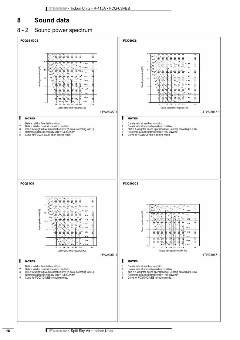
8 - 2 Sound power spectrum
4TW28927-1
NOTES
1 Data is valid at free field condition.2 Data is valid at nominal operation condition.3 dBA = A-weighted sound operation level (A-scale according to IEC).4 Reference acoustic intensity 0dB = 10E-6μW/m2
5 Curve for FCQ35-50C8VEB in cooling mode.
Sou
nd o
pera
tion
leve
l (dB
)FCQ35-50C8
Octave band center frequency (Hz)
4TW28947-1
NOTES
1 Data is valid at free field condition.2 Data is valid at nominal operation condition.3 dBA = A-weighted sound operation level (A-scale according to IEC).4 Reference acoustic intensity 0dB = 10E-6μW/m2
5 Curve for FCQ60C8VEB in cooling mode.
Sou
nd o
pera
tion
leve
l (dB
)
FCQ60C8
Octave band center frequency (Hz)
4TW28957-1
NOTES
1 Data is valid at free field condition.2 Data is valid at nominal operation condition.3 dBA = A-weighted sound operation level (A-scale according to IEC).4 Reference acoustic intensity 0dB = 10E-6μW/m2
5 Curve for FCQ71C8VEB in cooling mode.
Sou
nd o
pera
tion
leve
l (dB
)
FCQ71C8
Octave band center frequency (Hz)
4TW28967-1
NOTES
1 Data is valid at free field condition.2 Data is valid at nominal operation condition.3 dBA = A-weighted sound operation level (A-scale according to IEC).4 Reference acoustic intensity 0dB = 10E-6μW/m2
5 Curve for FCQ100C8VEB in cooling mode.
Sou
nd o
pera
tion
leve
l (dB
)
FCQ100C8
Octave band center frequency (Hz)

• Split Sky Air • Indoor Units 17
• Indoor Units • R-410A • FCQ-C8VEB
8 Sound data
8 - 2 Sound power spectrum
4TW28977-1
NOTES
1 Data is valid at free field condition.2 Data is valid at nominal operation condition.3 dBA = A-weighted sound operation level (A-scale according to IEC).4 Reference acoustic intensity 0dB = 10E-6μW/m2
5 Curve for FCQ125C8VEB in cooling mode.
Sou
nd o
pera
tion
leve
l (dB
)
FCQ125C8
Octave band center frequency (Hz)
4TW28987-1
NOTES
1 Data is valid at free field condition.2 Data is valid at nominal operation condition.3 dBA = A-weighted sound operation level (A-scale according to IEC).4 Reference acoustic intensity 0dB = 10E-6μW/m2
5 Curve for FCQ140C8VEB in cooling mode.S
ound
ope
ratio
n le
vel (
dB)
FCQ140C8
Octave band center frequency (Hz)
• Indoor Units • R-410A • FCQ-C8VEB
• Split Sky Air • Indoor Units18
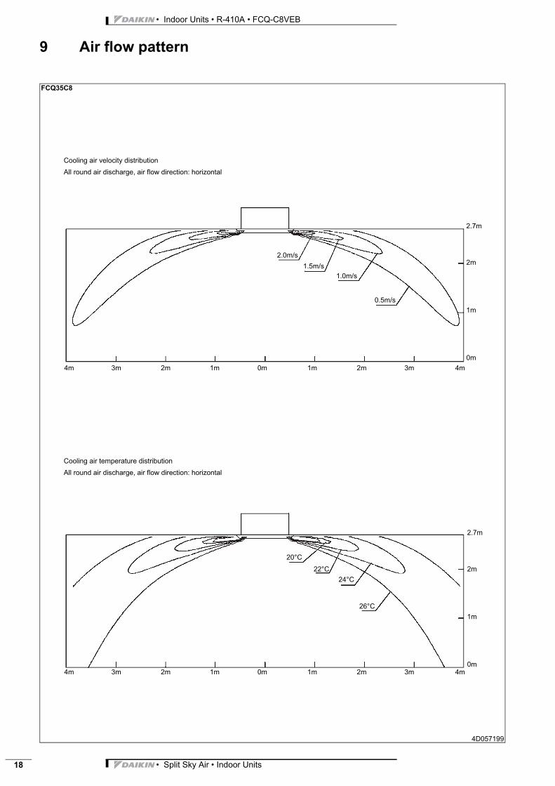
9 Air flow pattern
FCQ35C8
4D057199
Cooling air temperature distribution
All round air discharge, air flow direction: horizontal
Cooling air velocity distribution
All round air discharge, air flow direction: horizontal
4m 3m 2m 1m 0m 1m 2m 3m 4m
4m 3m 2m 1m 0m 1m 2m 3m 4m
2.7m
2m
1m
0m
2.0m/s
1.5m/s
1.0m/s
0.5m/s
20°C
22°C
24°C
26°C
2.7m
2m
1m
0m
• Split Sky Air • Indoor Units 19
• Indoor Units • R-410A • FCQ-C8VEB
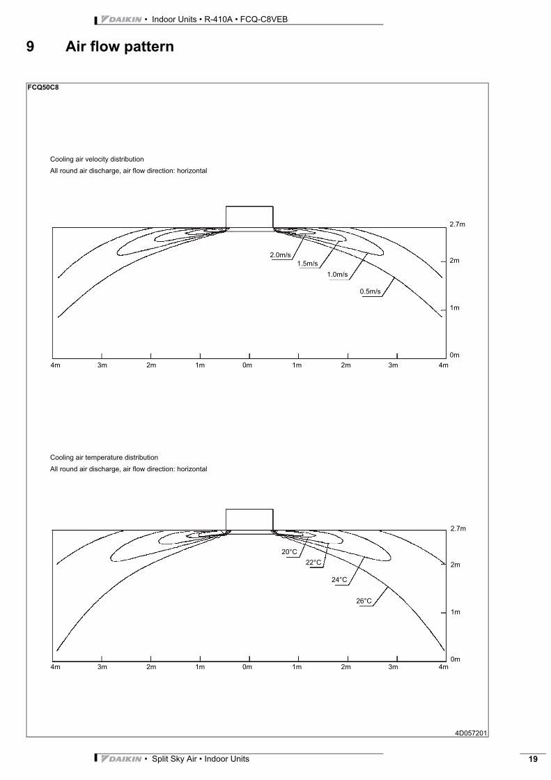
9 Air flow pattern
FCQ50C8
4D057201
Cooling air temperature distribution
All round air discharge, air flow direction: horizontal
Cooling air velocity distribution
All round air discharge, air flow direction: horizontal
4m 3m 2m 1m 0m 1m 2m 3m 4m
4m 3m 2m 1m 0m 1m 2m 3m 4m
2.7m
2m
1m
0m
2.0m/s
1.5m/s
1.0m/s
0.5m/s
20°C
22°C
24°C
26°C
2.7m
2m
1m
0m

• Indoor Units • R-410A • FCQ-C8VEB
• Split Sky Air • Indoor Units20
9 Air flow pattern
FCQ60C8
4D057203
Cooling air temperature distribution
All round air discharge, air flow direction: horizontal
Cooling air velocity distribution
All round air discharge, air flow direction: horizontal
4m 3m 2m 1m 0m 1m 2m 3m 4m
4m 3m 2m 1m 0m 1m 2m 3m 4m
2.7m
2m
1m
0m
2.0m/s
1.5m/s
1.0m/s
0.5m/s
20°C
22°C
24°C
26°C
2.7m
2m
1m
0m

• Split Sky Air • Indoor Units 21
• Indoor Units • R-410A • FCQ-C8VEB
9 Air flow pattern
FCQ71C8
4D057205
Cooling air temperature distribution
All round air discharge, air flow direction: horizontal
Cooling air velocity distribution
All round air discharge, air flow direction: horizontal
4m 3m 2m 1m 0m 1m 2m 3m 4m
4m 3m 2m 1m 0m 1m 2m 3m 4m
2.7m
2m
1m
0m
2.0m/s1.5m/s
1.0m/s
0.5m/s
20°C
22°C
24°C
26°C
2.7m
2m
1m
0m

• Indoor Units • R-410A • FCQ-C8VEB
• Split Sky Air • Indoor Units22
9 Air flow pattern
FCQ100C8
4D057207
Cooling air temperature distribution
All round air discharge, air flow direction: horizontal
Cooling air velocity distribution
All round air discharge, air flow direction: horizontal
4m 3m 2m 1m 0m 1m 2m 3m 4m
4m 3m 2m 1m 0m 1m 2m 3m 4m
2.0m/s
1.5m/s
1.0m/s0.5m/s
20°C
22°C
24°C
26°C
3.2m
3 m
2 m
1 m
0 m
3.2m
3 m
2 m
1 m
0 m

• Split Sky Air • Indoor Units 23
• Indoor Units • R-410A • FCQ-C8VEB
9 Air flow pattern
FCQ125C8
4D057209
Cooling air temperature distribution
All round air discharge, air flow direction: horizontal
Cooling air velocity distribution
All round air discharge, air flow direction: horizontal
4m 3m 2m 1m 0m 1m 2m 3m 4m
4m 3m 2m 1m 0m 1m 2m 3m 4m
3m
2m
1m
0m
2.0m/s
1.5m/s
1.0m/s0.5m/s
20°C
22°C
24°C
26°C
3.2m
3m
2m
1m
0m
3.2m

• Indoor Units • R-410A • FCQ-C8VEB
• Split Sky Air • Indoor Units24
9 Air flow pattern
FCQ140C8
4D057211
Cooling air temperature distribution
All round air discharge, air flow direction: horizontal
Cooling air velocity distribution
All round air discharge, air flow direction: horizontal
4m 3m 2m 1m 0m 1m 2m 3m 4m
4m 3m 2m 1m 0m 1m 2m 3m 4m
3m
2m
1m
0m
2.0m/s
1.5m/s1.0m/s
0.5m/s
20°C
22°C
24°C
26°C
3.2m
3m
2m
1m
0m
3.2m

• Split Sky Air • Indoor Units 25
• Indoor Units • R-410A • FCQ-C8VEB
9 Air flow pattern
FCQ35C8
4D057198
Heating air temperature distribution
All round air discharge, air flow direction: horizontal
Heating air velocity distribution
All round air discharge, air flow direction: horizontal
4m 3m 2m 1m 0m 1m 2m 3m 4m
4m 3m 2m 1m 0m 1m 2m 3m 4m
2.7m
2m
1m
0m
2.0m/s
1.5m/s
1.0m/s
0.5m/s
28°C
22°C
24°C
26°C
0.25m/s
2.7m
2m
1m
0m
27°C
25°C
23°C

• Indoor Units • R-410A • FCQ-C8VEB
• Split Sky Air • Indoor Units26
9 Air flow pattern
FCQ50C8
4D057200
Heating air temperature distribution
All round air discharge, air flow direction: horizontal
Heating air velocity distribution
All round air discharge, air flow direction: horizontal
4m 3m 2m 1m 0m 1m 2m 3m 4m
4m 3m 2m 1m 0m 1m 2m 3m 4m
2.7m
2m
1m
0m
2.0m/s
1.5m/s
1.0m/s
0.5m/s
26°C
2.7m
2m
1m
0m
24°C
22°C
23°C
25°C
27°C
28°C
0.25m/s

• Split Sky Air • Indoor Units 27
• Indoor Units • R-410A • FCQ-C8VEB
9 Air flow pattern
FCQ60C8
4D057202
Heating air temperature distribution
All round air discharge, air flow direction: horizontal
Heating air velocity distribution
All round air discharge, air flow direction: horizontal
4m 3m 2m 1m 0m 1m 2m 3m 4m
4m 3m 2m 1m 0m 1m 2m 3m 4m
2.7m
2m
1m
0m
2.0m/s
1.5m/s
1.0m/s
0.5m/s
26°C
2.7m
2m
1m
0m
24°C
22°C23°C
25°C
27°C
28°C
0.25m/s
• Indoor Units • R-410A • FCQ-C8VEB
• Split Sky Air • Indoor Units28
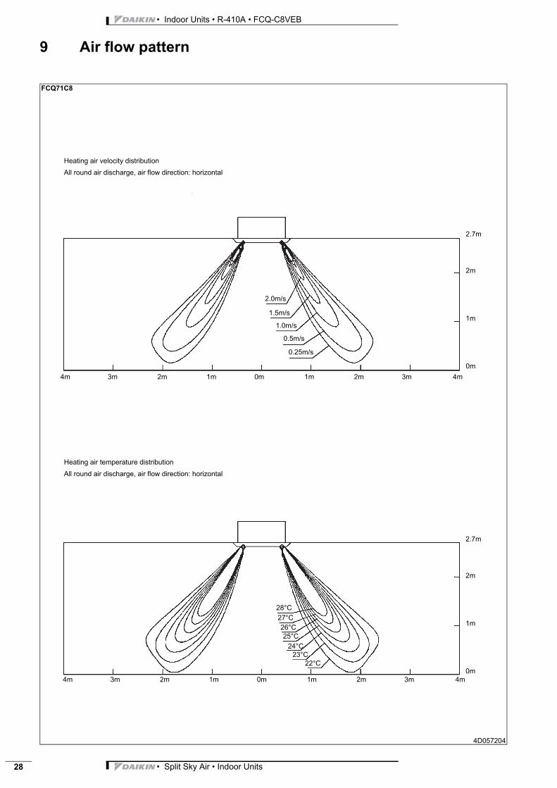
9 Air flow pattern
FCQ71C8
4D057204
Heating air temperature distribution
All round air discharge, air flow direction: horizontal
Heating air velocity distribution
All round air discharge, air flow direction: horizontal
4m 3m 2m 1m 0m 1m 2m 3m 4m
4m 3m 2m 1m 0m 1m 2m 3m 4m
2.7m
2m
1m
0m
2.0m/s
1.5m/s
1.0m/s
0.5m/s
26°C
2.7m
2m
1m
0m
24°C
22°C
23°C
25°C
27°C
28°C
0.25m/s
• Split Sky Air • Indoor Units 29
• Indoor Units • R-410A • FCQ-C8VEB
9 Air flow pattern
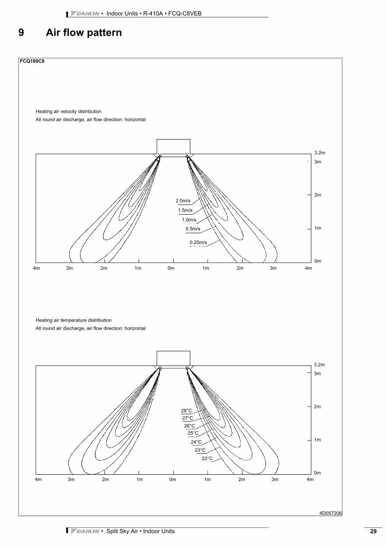
FCQ100C8
4D057206
Heating air temperature distribution
All round air discharge, air flow direction: horizontal
Heating air velocity distribution
All round air discharge, air flow direction: horizontal
4m 3m 2m 1m 0m 1m 2m 3m 4m
4m 3m 2m 1m 0m 1m 2m 3m 4m
2.0m/s
1.5m/s
1.0m/s
0.5m/s
26°C
3m
2m
1m
0m
24°C
22°C
23°C
25°C
27°C
28°C
0.25m/s
3.2m
3m
2m
1m
0m
3.2m
• Indoor Units • R-410A • FCQ-C8VEB
• Split Sky Air • Indoor Units30
9 Air flow pattern
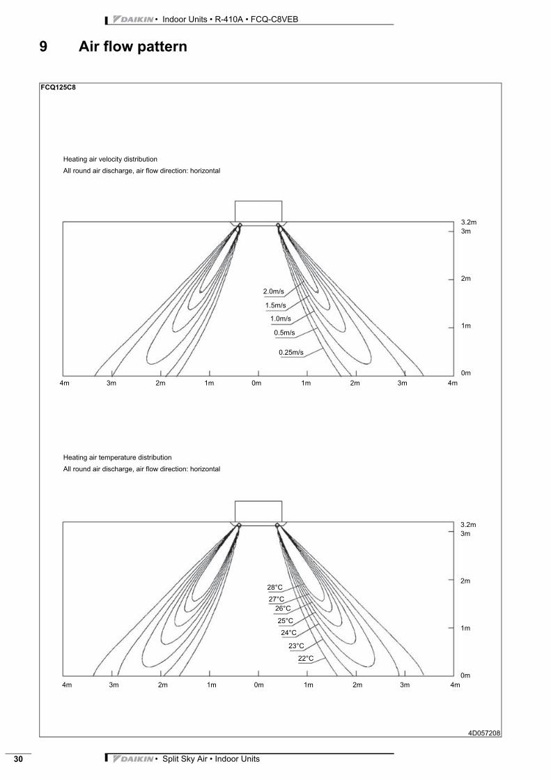
FCQ125C8
4D057208
Heating air temperature distribution
All round air discharge, air flow direction: horizontal
Heating air velocity distribution
All round air discharge, air flow direction: horizontal
4m 3m 2m 1m 0m 1m 2m 3m 4m
4m 3m 2m 1m 0m 1m 2m 3m 4m
2.0m/s
1.5m/s
1.0m/s
0.5m/s
26°C
3m
2m
1m
0m
24°C
22°C
23°C
25°C
27°C
28°C
0.25m/s
3.2m
3m
2m
1m
0m
3.2m
• Split Sky Air • Indoor Units 31
• Indoor Units • R-410A • FCQ-C8VEB
9 Air flow pattern
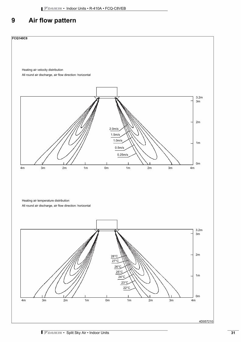
FCQ140C8
4D057210
Heating air temperature distribution
All round air discharge, air flow direction: horizontal
Heating air velocity distribution
All round air discharge, air flow direction: horizontal
4m 3m 2m 1m 0m 1m 2m 3m 4m
4m 3m 2m 1m 0m 1m 2m 3m 4m
2.0m/s
1.5m/s
1.0m/s
0.5m/s
26°C
3m
2m
1m
0m
24°C
22°C
23°C
25°C
27°C
28°C
0.25m/s
3.2m
3m
2m
1m
0m
3.2m
Daikin Europe N.V. is approved by LRQA for its QualityManagement System in accordance with the ISO9001standard. ISO9001 pertains to quality assurance regardingdesign, development, manufacturing as well as to servicesrelated to the product.
Daikin units comply with the European regulations thatguarantee the safety of the product.
Cop
yrig
ht D
aiki
nPr
epar
ed in
Bel
gium
by
Lann
oo (
ww
w.la
nnoo
prin
t.be)
, a c
ompa
ny w
hose
con
cern
for
the
envi
ronm
ont i
s se
t in
the
EMAS
and
ISO
140
01 s
yste
ms.
Res
pons
ible
Edi
tor:
Dai
kin
Euro
pe N
.V.,
Zand
voor
dest
raat
300
, B- 8
400
Oos
tend
e
The present publication is drawn up by way of information only and does notconstitute an offer binding upon Daikin Europe N.V.. Daikin Europe N.V. hascompiled the content of this publication to the best of its knowledge. Noexpress or implied warranty is given for the completeness, accuracy,reliability or fitness for particular purpose of its content and the products andservices presented therein. Specifications are subject to change withoutprior notice. Daikin Europe N.V. explicitly rejects any liability for any direct orindirect damage, in the broadest sense, arising from or related to the useand/or interpretation of this publication. All content is copyrighted by DaikinEurope N.V..
Daikin Europe N.V. is participating in the EUROVENTCertification Programme. Products are as listed in theEUROVENT Directory of Certified Products.
Naamloze VennootschapZandvoordestraat 300B-8400 Oostende, Belgiumwww.daikin.euBE 0412 120 336RPR Oostende
Daikin’s unique position as a manufacturer of airconditioning equipment, compressors andrefrigerants has led to its close involvement inenvironmental issues. For several years Daikin hashad the intension to become a leader in the provisionof products that have limited impact on theenvironment. This challenge demands the eco designand development of a wide range of products and anenergy management system, resulting in energyconservation and a reduction of waste.
ISO14001 assures an effective environmentalmanagement system in order to help protect human healthand the environment from the potential impact of ouractivities, products and services and to assist inmaintaining and improving the quality of the environment.