technical committee on september 9-11, 2015 agenda 1. … · september 9-11, 2015 agenda 1. call to...
TRANSCRIPT
Technical Committee on
Structural and Proximity Fire Fighting Protective Clothing and Equipment
NFPA 1971 FIRST DRAFT MEETING
Baltimore, MD
September 9-11, 2015
AGENDA
1. Call to order at 8:00am
2. Introductions
3. Opening remarks – Chairman King
4. Review and approval of minutes from previous meeting
5. NFPA Staff Liaison report - Chris Farrell
6. NFPA 1971 First Draft
a. Task Group Reports
b. Act on remaining Public Inputs
7. New business
8. Old business
9. Other items
10. Next meeting
11. Adjourn
MINUTES OF THE MEETING
TECHINICAL COMMITTEE ON STRUCTURAL AND PROXIMITY FIRE FIGHTING
PROTECTIVE CLOTHING AND EQUIPMENT
Hartford, CT
12-13 MAY 2015
PRE-FIRST DRAFT MEETING
12 May 2015
Agenda items 1 and 2: Call to Order, Introduction of Members and Guests
TC Chairman King called the meeting to order at 0900. Chairman King then called for an introduction of members and guests.
The following members and guests were present: Principal Members Present: Stephen King Chair Jason Allen Intertek Testing Services George Berger USMC/Marine Corps Systems Command Steven Corrado Underwriters Laboratories, Inc Paul Curtis L.N. Curtis & Sons David Fanning E.D. Bullard Company Patricia Freeman Globe Manufacturing Company, LLC A. Ira Harkness U.S. Department of the Navy William Haskell NIOSH-NPPTL Earl Hayden International Association of Fire Fighters John Karban FireDex, LLC Kim Klaren Fairfax County Fire & Rescue Department Steve Lakey Verified Independent Service Providers Association Karen Lehtonen Lion Group, Inc. Michael McKenna Michael McKenna & Associates, LLC Louis Ott Gentex Corporation Jim Reidy Texas State Association of Fire Fighters John Rihn Mine Safety Appliances Company Jeffrey Stull International Personnel Protection, Inc Tim Tomlinson Addison Fire Department
Robert Tutterow Fire Industry Equipment Research Organization Richard Weise Southern Area Fire Equipment Research Harry Winer HIP Consulting, LLC
Guests Present: Joey Underwood Safety Components Ron Bove W.L. Gore & Associates, Inc Kim Schoppa Fairfax County Fire & Rescue Department Jim Brinkley IAFF Robin Tintor UL Jessie Gentry DFW Airport R. Scott Colvin Maryland Fire Equipment Tom Lochner Fire Craft Safety Matt Culatrylio TenCate Tim Gardner 3M Tim Porch 3M Jen Brust Honeywell Kirk Owen Veridian Jordan Carlew DuPont Wayne Dora Lion James Baker Lion Total Care Holly Blake W.L. Gore Harish Lilani NORFAB Corp Mark Williams W.L. Gore & Associates Tyler Griffith Sturges Mfg Mike Allen Sturges Mfg Shawn Deaton NCSU Nick Galloway UL Jairo Rodriguez Miami-Dade Fire/Fire-Tec Angel Sanchez, Jr Phenix Technology, Inc
Alternate Members Present: Eric Buzard Mine Safety Appliances Company Nicholas Curtis Technical &Creative Resource Group Jonathan Fesik Fire Industry Repair Maintenance Inc. Robert Green International Association of Fire Chiefs Tricia Hock Safety Equipment Institute (SEI) Michael Laton Honeywell First Responder Products Marni Schmid (Secretary) Fortunes Collide Marketing/Alt. for F.I.E.R.O. Jeff Sedivec L.N. Curtis & Sons Daniel Silvestri Verified Independent Service Providers Association Jay Tarley National Institute for Occupational Safety & Health Patrick Woods Fire Department City of New York
Staff Liaison Chris Farrell National Fire Protection Association
Guests Present (cont’d): Shawn Russell Phenix Technology, Inc Allen Rom Fire-Dex Jacques Cantin Safety Components Stephen Asthalter Stanfield’s Chad Sears Stedfast Ed MacDonald Stanfield’s Ltd Charles Dunn TenCate Scott Cheek Honeywell Rich McNeely ORAFOL Brian Marenco Honeywell Chris Gaudette ORAFOL Americas Brian Barton Stedfast Michael Salvato Stedfast Jessica Ambrose Globe Manufacturing Bob Keys FDNY Consulting LLC Bryan Bolden PBI Jian Xiang DuPont Brian Shiels PBI Performance Products Diane Hess PBI Performance Products Elizabeth Easter University of Kentucky
Agenda Item 3: Staff Liaison Report:
Chris Farrell provided the NFPA Staff Liaison report including an overview of the Staff Liaison transition within the project, emergency procedures and other required notices. Chris also commented on the two TIAs that went to Standards Council: TIA 1159 – liquid penetration resistance test (1971); TIA 1160 – risk assessment (1851).
Agenda Item 4: Approval of the TC Minutes of San Antonio, TX meeting October 7-8,
2014:
Minutes approved
Agenda Item 5: Chairman’s Remarks:
Chairman King welcomed everyone to the meeting and reviewed the meeting agenda.
Robert Tutterow thanked those who came to and supported the 2015 Fire PPE Symposium and announced the 2017 dates and location (March 20-22, 2017, Raleigh.) Robert let everyone know to expect a notice for a call for presentations and described a marketing agreement with Pennwell.

Agenda Item 6: FPRF update – Casey Grant (Wednesday, May 13 PM):
Chairman King called on Casey Grant to present the cleaning project the Fire Protection Research Foundation is administering for the task group/TC.
Casey provided two websites, one for the foundation in general (www.nfpa.org/foundation) and one for the PPE Cleaning project specifically (www.nfpa.org/PPEcleaning) and he gave a general overview of the projects the foundation is working on noting that a full summary is available on the webpage.
Anyone interested in receiving final reports for the project can go to the website and sign up for emails.
Agenda Item 7: Task Group Reports:
Risk Assessment – Structural vs Proximity – Earl Hayden
o Earl Hayden reviewed proposed changes to the proposed TIA and the committee discussed those changes and made additional edits.
Helmets – Dan Melia
o Tricia Hock (reporting for Dan Melia) discussed the TIA that went out to the committee Monday, May 11 and discussed broader issues the task group is trying to address.
Gloves – Michael McKenna
o Mike McKenna discussed the task group’s progress in studying glove testing and glove sizing issues. Public Inputs will be submitted related to both projects.
Hoods – Jim Reidy
o Jim Reidy reviewed the two issues the task group is reviewing: (1) the face opening and hood creep down and (2) layers/particulate protection. Testing will continue.
Cleaning/Decontamination – Tim Tomlinson
o Tim Tomlinson gave a project update – the task group has handed the cleaning study over to the Fire Protection Research Foundation for administration. While the study is underway, the task group will continue working on other projects.
DRD – Rick Edinger (Steve Lakey reporting)
o Steve Lakey (reporting for Rick Edinger) distributed a survey the task group would like to conduct with the intent of using the data gathered to submit Public Inputs to update the DRD section of the standard.
Annexes – Robert Tutterow
o Robert Tutterow provided background on the Annex project and discussed next steps. The Annexes will be submit as Public Input.
Garments
o Chairman King asked Karen Lehtonen to report on a letter she sent to him on behalf of the ASTM F23 committee providing a status update related to the WICHR Test Method. Brian Shiels initiated a discussion and changes to AATCC TM135 related to preconditioning.

Common Chemicals – Dick Weise
o Dick Weise reported that the task group developed and conducted a survey of the fire service that may lead to Public Inputs related to section 8.27.
Agenda Item 8: Task Group Breakout Sessions as required
Tuesday afternoon 2pm, TC reconvenes Wednesday, October 8 at 9am
Agenda Item 9: Old Business
No Old Business to discuss
Agenda Item 10: New Business
The committee discussed three New Business items: (1) mobile repair units and verification issues, (2) data and (3) next meeting date and location.
o A task group named Mobile ISPs was formed and the members are: Tim Tomlinson (Chair) Jason Allen Jessica Ambrose Steve Corrado Paul Curtis Jonathan Fesik Steve Lakey Dick Weise
o The Correlating Committee will discuss data reporting issues at the meeting May 14-15
o The NFPA 1971 First Draft Meeting will be held September 9-11, 2015 in Baltimore.
Agenda Item 11: Adjournment
Chairman King adjourned the meeting at 3:12 p.m. CT on Wednesday, May 13, 2015. Harry Winer moved to adjourn, Jonathan Fesik second. Motion passed.
Public Input No. 130-NFPA 1971-2015 [ Global Input ]
Converting current sizes with new sizes globally throughout document as follows:
(1) Replace Extra, extra small (XXS) with 64N (Normal)
(2) Replace Extra small (XS) with 70N (Normal)
(3) Replace Small (S) with 70W (Wide)
(4) Replace Medium (M) with 76N (Normal)
(5) Replace Large (W) with 76W (Wide)
(6) Replace Extra large (XL) with 82N (Normal)
(7) Replace Extra, extra large (XXL) with 82W (Wide)
Statement of Problem and Substantiation for Public Input
see new proposed sizing system section 6.7.6 and related public comments
Related Public Inputs for This Document
Related Input Relationship
Public Input No. 127-NFPA 1971-2015 [Section No. 6.7.6 [Excluding any Sub-Sections]]
global change that needs to take place if new sizing system is adopted
Submitter Information Verification
Submitter Full Name: Mark Williams
Organization: W.L. Gore & Associates, Inc.
Affilliation: W.L. Gore & Associates, Inc.
Street Address:
City:
State:
Zip:
Submittal Date: Tue Jun 23 18:03:30 EDT 2015
Public Input No. 185-NFPA 1971-2015 [ Global Input ]

7.20.1.1. The entire CBRN protective ensemble shall be tested for overall inward leakage as specified in Section 8.66,Man-In-Simulant Test (MIST), and shall have an average local physiological protective dosage factor (PPDFi) value at each PAD location for the four ensembles tested of no less than 360. 0 120.0 and a systemic physiological protective dosage factor (PPDFsys) value for each tested ensemble no less than 361.0 76.0.
A.7.20.1.1. The minimum local physiological protective dosage factor is based on the
NIOSH conditions used for CBRN SCBA APR (i.e., 300 50 mg/m3 × 3 0 60 min = 9000 3000 mg/min/m3) in evaluating the permeation of the blister agent, distilled mustard (HD). This maximum exposure concentration is divided by the onset of symptoms exposure dosage (OSED), which is set at an exposure concentration (10) value that causes threshold mustard effects of blistering and ulceration in 10 percent of the population. Since blister agent effects vary with the body location, different values of the onset of symptoms exposure dosage are used for each body location (which vary from 25 to 100 mg/min/m3). The reported value for local physiological protective dosage factor is normalized at each location so that each local physiological protective dosage factor is compared on the same basis. The systemic physiological protective dosage factor is based on NIOSH conditions used for CBRN SCBA APR (i.e., 2000 210 mg/m3 × 3 0 60 min = 60,0 00 12,6 0 0 mg.min/m3) in evaluating the permeation of the nerve agent, sarin (GB), where the soman (GD) concentration is assumed to be equivalent to the GB concentration specified in the standard. The onset of symptoms exposure dosage OSED used to calculate the minimum systemic physiological protective dosage factor for GD is 166 mg/min/m3 (Grotte, J. H. and Yang, L. I., “Report of the Workshop on Chemical Agent Toxicity for Acute Effects,” IDA Document D-2176, Institute for Defense Analysis, Alexandria, VA, May 1998). This value is the dosage of GD that produces threshold effects of twitching and localized sweating for 10 percent of the population (10).
8.67.4.1Specimens shall be tested for permeation resistance for not less than 60 minutes
against the chemicals specified in 8.67.4.2 and 8.67.4.3 in accordance with ASTM F 739, with the following modifications:
1. (1) The test cells shall be designed to accommodate the introduction of liquid chemicals in a safe manner.
2. (2) Testing shall be conducted in an open-loop configuration for the collection of permeant.
3. (3) The collection media shall be filtered air flowed through the bottom of the test cell at a rate of 1 Lpm, ±0.1 Lpm, with a relative humidity of 80 percent, ±5 percent.
4. (4) Analytical methods used shall be sensitive to the permeant at concentrations of at least one order of magnitude lower than the required end points.
5. (5) Where cumulative permeation end points are not specified in this standard, a permeation rate of 0.1 ìg/cm2/min, as defined by ASTM F 739, shall be used.
8.67.4.4.1 For permeation tests involving gases, the gas concentration shall be 350 40
ppm, 50/-0 10/-0 ppm, and the test cell shall be assembled in the closed-top configuration.
8.67.4.4.2. For permeation tests involving liquids, the liquid concentration density shall be
10 g/m2, 1/-0 g/m2, and the cell shall be assembled in closed-top open-top configuration.
The liquid drops shall be applied as nominal 1 ìl drops uniformly distributed over the test area of the sample surface. Where a seam, closure, or fixture is included, at least one drop shall be applied to each critical juncture, such as the seam edge.
Additional Proposed Changes
File Name Description Approved
Hold_1971_Log_CC29_Comment_on_Proposal_1971-74.pdf
NFPA 1971, 1971-90, Log 37 Hold
Statement of Problem and Substantiation for Public Input
NOTE: This Public Input appeared as "Reject but Hold" in Public Comment No. 1971-90, Log 37 of the F2011 Second Draft Report for NFPA 1971 and per the Regs. at 4.4.8.3.1. Paragraph A.1.3.2 of NFPA 1971 limits the application of CBRN ensembles for escape only, not entry, yet requires the challenges associated with a Class 2 ensemble. This function of the ensemble is in contrast to NFPA 1994, which permits first responder entry into IDLH environments which require the use of CBRN SCBA for Class 2 requirements after which the optional NFPA 1971 requirements were modeled. The NFPA 1971 application is inconsistent with the performance criteria in Class 2; therefore, it is recommended that the Class 3 criteria from NFPA 1994 be applied to NFPA 1971 CBRN ensembles.
Submitter Information Verification
Submitter Full Name:
TC ON FAE-SPF
Organization: NFPA Correlating Committee on Fire and Emergency Services Protective Clothing and Equipment
Street Address:
City:
State:
Zip:
Submittal Date: Thu Jul 02 12:33:22 EDT 2015
Public Input No. 209-NFPA 1971-2015 [ Global Input ]
Type your content here ... Information to help fire fighters, specifiers, and other individuals better understand performance requirements and test methods used in the evaluation of structural fire fighting protective ensemble elements within Chapters 7 and 8 is provided as part of Annex C.
Statement of Problem and Substantiation for Public Input
General descriptions for the different performance criteria and related test methods used for qualifying structural fire fighting protective ensemble elements have been developed to enable
fire fighters, specifiers, and other individuals to better understand how ensemble elements are tested and provide information on what the test results mean. This non-mandatory information is intended to help improve awareness for the use of performance criteria and test methods within the standard.
Submitter Information Verification
Submitter Full Name: ROBERT TUTTEROW
Organization: FIRE INDUSTRY EQUIPMENT RESEAR
Street Address:
City:
State:
Zip:
Submittal Date: Sun Jul 05 08:06:50 EDT 2015
Public Input No. 225-NFPA 1971-2015 [ Global Input ]
All referenced standards should be reviewed and updated to reflect the current editions if appropriate.
Statement of Problem and Substantiation for Public Input
Referenced standards should be reviewed and updated if appropriate.
Submitter Information Verification
Submitter Full Name: STEVEN CORRADO
Organization: UL LLC
Street Address:
City:
State:
Zip:
Submittal Date: Mon Jul 06 08:40:43 EDT 2015
Public Input No. 251-NFPA 1971-2015 [ Global Input ]
Remove Requirements, Test Methods, and Other Language associated with CBRN Terrorism Agent Protection.
It is proposed that the CBRN requirements be moved from NFPA 1971-2013 and transitioned into NFPA 1994 under the category of a multiple use Class 2 set of design, performance, labeling, and certification criteria. This would enable the specific test methods associated with the optional CBRN requirements to be maintained by the Technical Committee on Hazardous Materials Protective Clothing and Equipment that is responsible for the NFPA 1994 standard. Currently, the same an opinion tonight for Class 2 are used in NFPA 1971 with the principal differences being the type of conditioning for materials and elements prior to testing. The proposed new multiple use Class 2 would account for the current rigorous conditioning of materials to demonstrate continued service of ensemble elements prior to the expected use in a CBRN environment.
The required changes would involve:
1. Modification of the Chapter 1 scope, purpose, and definitions; however, it is proposed that an Annex section remain in place that explains that if a structural or proximity fire fighting protective ensemble were to be represented for CBRN protection that it should be also certified to the multiple use requirements in NFPA 1994.
2. Removal of Section 7.20 Optional Performance Requirements for Protection from CBRN Terrorism Agents.
3. Deletion of Sections 8.65, 8.66, 8.67, 8.68 and 8.69 on test methods that are specific for CBRN protective ensembles and elements.
4. Other revised language in the standard for removal or modification of paragraphs with specific references to CBRN protective ensembles and elements.
Statement of Problem and Substantiation for Public Input
The removal of the CBRN criteria and related requirements are intended to ease the workload on the Technical Committee and transfer responsibility for maintaining the detailed test methods and criteria to the Technical Committee on Hazardous Materials Protective Clothing and Equipment. The ability to link CBRN protection to structural or proximity firefighting protective ensembles will still be possible by dual certification of ensembles to your proposed multiple use criteria for NFPA 1994 Class 2 ensembles. This change is consistent with a recent recommended change considered by the Correlating Committee for Fire and Emergency Services Protective Clothing and Equipment.
Submitter Information Verification
Submitter Full Name: JEFFREY STULL
Organization: INTERNATIONAL PERSONNEL PROTECTION, INC.
Street Address:
City:
State:
Zip:
Submittal Date: Mon Jul 06 15:58:30 EDT 2015
Public Input No. 256-NFPA 1971-2015 [ Global Input ]
ADDITION OF NEW ENSEMBLE CATEGORY FOR PARTICULATE PROTECTIVE ENSEMBLE
It is proposed that a new category of optional ensemble performance be established to address overall particular protection of firefighters to limit their exposure to smoke and associated carcinogens carried by smoke particles. It is specifically proposed that the current optional CBRN language be transformed to address the evaluation of ensembles for particle holdout using the current NFPA 1994, Class 4 criteria where the Department of Defense Testing Operating Procedure for aerosol man in simulant testing be applied. In addition, specific product labeling requirements similar to those established for optional CBRN terrorism agent protection be applied.
Additional Proposed Changes
File Name Description Approved
RTI_Test_Report_-_Fluorescent_Aerosol_Screening_Test_-_2015.pdf
Statement of Problem and Substantiation for Public Input
Several studies have been performed over the past several decades to characterize the constituents of fireground smoke [1-5]. Not unexpectedly, smoke from structural fires contains a large variety of different types of particulates and chemicals. The composition of fireground smoke and the related particulates and aerosols in the response environment depend heavily on the materials used in construction of the particular structure and its related contents. These studies have shown the presence of several hazardous chemicals at elevated concentrations including carbon monoxide, nitrogen dioxide, hydrogen chloride, hydrogen cyanide, sulfur dioxide, acrolein, formaldehyde, acetaldehyde, benzene, and several other volatile organic chemicals [4]. However, the principal component of fire smoke is soot, which consists primarily of carbon particles, but may also include silica, asbestos and other minerals. The carbon particles are the principle decomposition product of materials and chemicals during combustion and have the added feature in their ability to adsorb volatile and semi-volatile chemicals during their release and suspension into the fireground environment [6-7]. This particular characteristic is significant because many chemicals can remain trapped on the surface or inside the carbon particles as they deposit onto surfaces and become entrained within materials exposed to the fireground environment, such as the protective clothing worn by fire fighters. Other studies have been conducted to characterize how fire fighter protective clothing becomes contaminated through its use on the fireground [8-11]. These studies suggest a variety of contamination levels but generally demonstrate clothing materials to retain chemicals which are less volatile but considerably dangerous you such as known carcinogens including polyaromatic hydrocarbons (PAHs). These semi-volatile chemicals are persistent and are less likely to be removed by general cleaning methods [8,9]; these chemicals are also known to permeate skin [12]. Research undertaken in Australia specifically showed how many of these chemicals not only contaminate clothing, but penetrate through clothing layers or through interface areas to reach the firefighter’s skin [10,11]. A more recent study has indicated that skin in the neck/head area of firefighters is the portion of their bodies that are most likely to become contaminated with fire ground substances and chemicals [13]. In fact, this study specifically recommended further research to: Study the effect of turnout hood designs and materials on dermal exposure and absorption of combustion products. The neck was the only skin site where we measured
elevated levels of PAHs that were statistically significant (for round 1) and was also a possible site for dermal absorption of aromatic hydrocarbons (e.g., benzene). Providing better protection to the neck could reduce dermal absorption of combustion products. Work carried out by the International Association of Fire Fighters (IAFF) has demonstrated that particles using the same in a P 1994, Class IV test indicated above can readily penetrate into firefighter protective ensembles to interface areas and the protective hood. A copy this report will be made available to the technical committee. [1] Brandt-Rauf, PW, LF Fallon, Jr., T Tarantini, C. Idema, and l. Andrews (1988). “Health hazards of firefighters: Exposure assessment.” Brit J Ind Medicine 45: 606-612. [2] Jankovic J, W Jones, J Burkhart, and G Noonan (1991). Environmental study of fire fighters. Ann Occup Hyg 35(6): 581–602. [3] Guidotti TL and VM Clough.(1992). “Occupational health concerns of firefighting." Ann Rev Public Health 13(1): 151-171. [4] Lees, PSJ (1995). “Combustion Products and Other Firefighter Exposures.” Occup Med: State of the Art Reviews 10(4): 691-706. [5] Austin CC, D Wang, DJ Ecobichon, and G Dussault (2001). “Characterization of volatile organic compounds in smoke at municipal structural fires.” J Toxicol Environ Health A 63(6): 437-458. [6] Stone, JP, RN Hazlett, JE Johnson (1973). “The Transport of Hydrogen Chloride by Soot from Burning Polyvinyl Chloride.” J. Fire Flammability, 4: 42-48. [7] Butler, KM and GW Mulholland (2004). “Generation and transport of smoke components.” Fire Technology 40(2): 149-176. [8] Stull, JO, CR Dodgen and RT McCarthy (1996). “Evaluating the effectiveness of different decontamination and laundering approach for structural fire fighting clothing.” Performance of Protective Clothing: Fifth Volume, ASTM STP 1237 (J. S. Johnson and S. Z. Mansdorf, eds.), ASTM, Philadelphia: 447-470. [9] Kingsland, C (2003). “Analysis of soil removal from firefighter turnout gear; an evaluation of care and maintenance procedures.” Masters’ Thesis, University of Kentucky. [10] QFRS (2011a). Fire fighter exposures to airborne contaminants during extinguishment of simulated office room fires. By Kirk KM, Ridgway M, Splawinski Z, Logan MB. Queensland, Australia: Queensland Fire and Rescue Service (QFRS) Scientific Branch, Research Report 2011-02. [11] QFRS (2011b). Fire fighter exposures to airborne contaminants during extinguishment of simulated residential room fires. By Kirk KM, Ridgway M, Splawinski Z, Logan MB. Queensland, Australia: Queensland Fire and Rescue Service (QFRS) Scientific Branch, Research Report 2011-01. [12] Feunekes FD, FJ Jongeneelen, H vd Laan, and FH Schoonhof (1997). “Uptake of polycyclic aromatic hydrocarbons among trainers in a fire-fighting training facility.” Am Ind Hyg Assoc J 58(1): 23–28. [13] Fent KW et al (2013). “Evaluation of dermal exposure to polycyclic aromatic hydrocarbons in fire fighters.” Health Hazard Evaluation Program Report No. 2010-0156-3196, U.S. Dept. of Health and Human Services.
Submitter Information Verification
Submitter Full Name: JEFFREY STULL
Organization: INTERNATIONAL PERSONNEL PROTECTION, INc.
Street Address:
City:
State:
Zip:
Submittal Date: Mon Jul 06 16:30:12 EDT 2015
Public Input No. 259-NFPA 1971-2015 [ Global Input ]
Adopt Liquid Chemical Runoff Test
Incorporate a similar test as presented in paragraph 4.4.10 in ISO 11613 for the measurement of liquid chemical runoff for outer shell materials. The testing is based on ISO 6530.
Statement of Problem and Substantiation for Public Input
It is proposed that a liquid chemical runoff test be applied to outer shell materials similar to that used within ISO 11613 that is performed in accordance with ISO 6530. This test is proposed since it may be an indicator for the contamination resistance of outer shell materials that is currently not addressed within NFPA 1971. Contamination resistance of the outer shell will forward less pickup of chemical contaminants during fire ground activities and result in easier cleaning of turnout clothing.
Submitter Information Verification
Submitter Full Name: JEFFREY STULL
Organization: INTERNATIONAL PERSONNEL PROTECTION, INC.
Street Address:
City:
State:
Zip:
Submittal Date: Mon Jul 06 16:44:53 EDT 2015
Public Input No. 29-NFPA 1971-2013 [ Global Input ]
Note: This Public Input originates from Tentative Interim Amendment 1971-13-1 (TIA 1058) issued by the Standards Council on January 3, 2013.
All of the text exists in the current document. See the uploaded Balloted TIA.
Additional Proposed Changes
File Name Description Approved
Proposed_TIA_1058_1971_rev_5_2_12_.docx Balloted TIA
Statement of Problem and Substantiation for Public Input
During the new business item of the NFPA 1851 ROC meeting in San Antonio on April 3 and 4, 2012 a situation with the new ASTM F2700 test method as it relates to NFPA 1971 was brought up. After much discussion of the available data and the differences in the data of both TPP test methods for the same composites, the Technical Committee agreed that there was a need to file a TIA for NFPA 1971 based on the significance of the data presented at the meeting and the potential to negatively affect the end users. It was not the intent of the Technical Committee to

increase or decrease the TPP value as the Committee agreed during the process that a 35 TPP as a minimum would adequately protect the firefighter. Technical Merit: In the F2011 Report on Proposals for 1971-151 (Log #103), the Technical Committee on Structural and Proximity Fire Fighting Protective Ensembles provided an action for replacing the currently referenced ISO 17492 test method that measures thermal protective performance (TPP) with ASTM F2700. This change was believed to offer equivalent procedures and to provide additional details in conducting the test. Nevertheless, some of the specific details provided in the newer ASTM F2700 test method have been found to cause apparent significant differences in the currently reported TPP values for coat and pant garment material composites. Limited laboratory work using ASTM F2700 has neither resulted in the identification of any specific correlation that can be made for the amount of offset in TPP values that is resulting from the implementation of the new test method nor the determination of differences between the two test methods that can explain the variation of test results. Furthermore, it is unknown what effects the new test method will have on other types of composites being used in other elements, such as helmet ear covers, gloves, hoods, and wristlets. Emergency Nature: The implementation of the new ASTM F2700 test method in place of the existing ISO 17492 test without reviewing the current performance criteria, has the potential of disqualifying a significant number of currently acceptable material composites that are used in the construction of structural firefighter protective clothing and will have unknown effects on the qualification of other structural firefighting protective elements such as gloves, hoods, and helmet ear covers. The protective garment material composites that are most likely to be affected by this change represent the many of the industry composites that have thermal protective performance (TPP) values in the range of 35 to 40 cal/cm2 and the corresponding higher values of total heat loss levels that are positioned to lessen the stress effects for wearing protective clothing. The observed differences in TPP values were not the result of changes in the material technology and there was no intention of increasing the level of thermal protection and insulation provided by firefighter protective clothing. Therefore, the proposed TIA intends to correct a circumstance in which the revised document has resulted in an adverse impact on both products and the TPP method that was inadvertently overlooked in the total revision process.
Submitter Information Verification
Submitter Full Name:
TC on FAE-SPF
Organization: TC on Structural and Proximity Fire Fighting Protective Clothing and Equipment
Street Address:
City:
State:
Zip:
Submittal Date: Mon Sep 09 10:19:20 EDT 2013
Public Input No. 65-NFPA 1971-2015 [ Global Input ]
The Standard 1971 should include the suspenders for PPE trouser as part of the complete PPE ensemble. No or limited guidance is provided for belted trouser without suspender. When wet or while crawling in hostile environments, the trouser may sag and expose areas between

coat and trouser or allow the trouser to drag under the boot heal causing fray. In addition, in firefighter mayday scenarios when a firefighter may be unconscious unable to assist in evacuation, other firefighters may grab the trouser. The trouser may become dislodged or pulled down during rescue efforts. Suspenders will aid in preventing unintentional doffing of trouser pant.
Suspenders should be a part of all protective ensembles.
Statement of Problem and Substantiation for Public Input
Absence of guidance on trouser suspenders for PPE.
Submitter Information Verification
Submitter Full Name: ANDREW BARR
Organization: MCKINNEY FIRE DEPARTMENT
Street Address:
City:
State:
Zip:
Submittal Date: Wed Mar 18 11:14:51 EDT 2015
Public Input No. 92-NFPA 1971-2015 [ Global Input ]
3.3.X Component Recognized/Component Recognition. A system whereby a
certification organization determines that a manufacturer has demonstrated the ability to produce a material, component, or product assembly that complies with the applicable requirements of this standard and establishes a follow-up program conducted by the certification organization as a check on the methods the manufacturer uses to determine continued compliance of listed materials, components, and product subassemblies with the applicable requirements of this standard.
Add new subsection to 4.1 (recommended to be positioned after current paragraph 4.1.7):
4.1.X Certification organizations shall be permitted to provide component recognition for
materials, components, and product subassemblies in accordance with the following requirements.
4.1.X.1 Certification organizations shall only provide component recognition for those
materials, components, and product subassemblies where specific design and performance criteria can be directly applied, where the specific criteria is not dependent on material, component, or product subassembly conformance to other criteria in this standard, and where the responsibility for the material, component, or product subassembly can be attributed to a single manufacturer.

A.4.1.X.1 Only those materials, components, and product subassemblies that can be
separately tested to specific requirements in this standard can be subjected to component recognition. For example, an outer shell material can be independently evaluated for flame resistance, heat resistance, thermal shrinkage resistance, tear strength, tensile strength, cleaning shrinkage, and water absorption resistance, and thus can be component recognized. Similarly, glove moisture barriers can be component recognized in some instances because even though the requirement specifies testing of the glove composite and seams, the conditioning used to qualify the moisture barrier specifies a particular material lay-up for testing both liquid penetration resistance and viral penetration resistance that is independent of the glove construction. It is also possible that the manufacturer of the glove moisture barrier is also responsible for the construction of the glove moisture barrier seams, when provided as an insert. In contrast, the toe reinforcement of footwear cannot be subjected to applicable testing without the mounting of the toe reinforcement in the footwear toe and thus cannot be component recognized. In the case of a garment composite, while it is possible to independently test a composite consisting of outer shell, moisture barrier, and thermal barrier for thermal protective performance and total heat loss testing, unless all three layers are provided by the same manufacturer, then component recognition cannot be applied.
4.1.X.2 Certification organizations that provide component recognition shall meet all of the
requirements specified in Section 4.2, Certification Program, and Section 4.3, Inspection and Testing.
4.1.X.3 Certification organizations that provide component recognition shall require
manufacturers of materials, components, and product subassemblies that are subject to component recognition to meet the applicable requirements specified in Section 4.4, manufacturers' Quality Assurance Program.
4.1.X.4 Materials, components, and product subassemblies that meet the respective
applicable requirements of this standard shall be listed.
Add new paragraph to Section 4.3 (insert after current paragraph 4.3.2.2)
4.3.X If requested by the manufacturer submitting for certification, the certification
organization shall accept component recognition for those materials, components, or product subassemblies that have been component recognized by a different certification organization. This organization shall (1) meet the requirements of Section 4.2, Certification Program, (2) provide evidence of compliance for its conformity with the requirements for a certification organization, and (3) meet the applicable requirements of the product certification organization accepting the recognized components (see 4.3.Y).
4.3.Y A certification organization shall have a process for developing requirements, which
when fulfilled, will be the basis for utilization of certification of components from another certification organization meeting the requirements of this standard in the certification of the end product.
4.3.Z When the requirements developed through the above process are fulfilled, the
resultant utilization of certifications of components from another certification organization shall be comparable to either (1) the utilization of the certification organization’s own certification of components; or if the certification organization does not certify components, (2) the certification organization’s acceptance of results of evaluations from external sources.
Additional Proposed Changes
File Name Description Approved
Hold_1971-4_Log_86_Comment_on_Proposal_1971-11.pdf
Hold_1971-4_Log_86_Comment_on_Proposal_1971-11
Statement of Problem and Substantiation for Public Input
This Public Input appeared as "Reject but Hold" in Public Comment No. 1971-11 of the F2011 Second Draft Report for NFPA 1971 and per the Regs. at 4.4.8.3.1. The original proposal was rejected because no agreement was reached at the Technical Correlating Committee for the implementation of this proposal. However, the proposed language, which is slightly different than that which appeared in the original proposal has been adopted as part of another standard - NFPA 2112 - on flash fire protective clothing.
Submitter Information Verification
Submitter Full Name:
TC ON FAE-SPF
Organization: NFPA TC on Structural and Proximity Fire Fighting Protective Clothing and Equipment
Street Address:
City:
State:
Zip:
Submittal Date: Tue May 12 11:17:54 EDT 2015
Public Input No. 93-NFPA 1971-2015 [ Global Input ]
Insert Proposed Performance Criterion
7.10.X Footwear shall be tested for agility performance as specified in 8.X and shall have an average percentage change in agility course time of no greater than 10 percent.
Insert Proposed Test Method in Chapter 8
8.X Footwear Agility Performance Test.
8.X.1 Application. This test shall apply to footwear.
8.X.2 Samples.
8.X.2.1 Samples for conditioning shall be whole footwear pairs.
8.X.2.2 Footwear pair samples shall be preconditioned as specified in 8.1.3.
8.X.3 Specimens.

8.X.3.1 A minimum of five footwear pairs shall be used for specimens, each with a different test subject wearing each pair of footwear.
8.X.3.2 Each pair of footwear shall be tested as a complete set of footwear in new, as distributed, condition.
8.X.3.3 Footwear pair specimens shall not receive special softening treatments prior to tests.
8.X.4 Apparatus and Test Subjects
8.X.4.1 Test Course.
8.X.4.1.1* The test apparatus shall consist of an agility course laid out on a smooth, completely flat, wooden floor surface with cones positioned as shown in Figure 8.X.4.1.1.
***Insert 1971_L115_FIG 8.X.4.1.1_F2011_R here*** See PDF Attachment
8.X.4.1.2 Tape shall be used to mark the position of each cone and the starting and finishing line of the agility course.
8.X.4.1.3 Eight 30 cm (12 in.) high traffic cones shall be used for marking the course as shown in 8.X.4.1.1.
8.X.4.2 Test Subjects.
8.X.4.2.1 Test subjects shall be selected so that they are able to complete the agility course wearing athletic running shoes in an average time of 20 seconds or less with a variation of no more than 10% as measured over three consecutive trials at 6 to 7 minute intervals after the test subjects has become accustomed to the course.
8.X.4.2.2 Each test subject shall wear their own athletic running or cross training shoes for all baseline tests. The test subject shoes shall be in good condition and shall fit the test subject correctly.
8.X.4.2.3 Each test subject shall be fitted with the correct size of test footwear involving a fitting process where a range of sizes for test footwear are made available to the test subject to allow their choice of the best fitting size.
8.X.4.2.4 Each test subject shall wear a pair of running shorts and T-shirt while running the agility course. Normal athletic socks shall be worn when wearing either the athletic running shoes or the test footwear.
8.X.4.2.5 No individual test subject shall run more than 15 tests in a day.
8.X.4.3 Test Operator.

8.X.4.3.1 The test operator for the test shall serve as the starter and timer for all tests conducted within a series of baseline and test footwear evaluations.
8.X.4.3.2* A stopwatch with an accuracy of ±0.05 second shall be used to measure the agility course time for each test subject.
8.X.4.3.3 The test operator shall use the starting commands, “on your mark, get set, go” establishing the same cadence of stating the commands for each test, starting the stop watch upon saying “go.”
8.X.4.3.4 The test operator shall stop the watch when the test subject’s leading foot crosses the finish line.
8.X.5.1 Each test subject shall become familiar with the agility course by first walking the agility course three times and then running the agility course three times while wearing their own athletic running shoes. An interval of at least 6 to 7 minutes shall be used between successive runs of the agility course.
8.X.5.2 Each test subject shall run the agility course three times while wearing their own athletic running shoes to establish baseline times for running the agility course as measured using a stopwatch. An interval of at least 6 to 7 minutes shall be used between successive runs of the agility course.
8.X.5.3 Each test subject shall remove their athletic footwear, don the test footwear, and walk the agility course three times while wearing the test footwear before conducting any timed tests; if any subject has a complaint about the specific footwear, the test subject shall be refit with a different pair of footwear as specified in 8.X.4.6. This step shall be concluded within 15 minutes after finishing the third baseline test specified in 8.X.5.2.
8.X.5.5 Each test subject shall run the agility course a total of three times while wearing the test footwear to establish test times for running the agility course as measured using the stopwatch. An interval of at 6 to 7 minutes shall be used between successive runs of the agility course.
8.X.5.6 Each test subject shall then remove the test footwear, put on their athletic running shoes, and shall run the agility course three additional times while wearing their own athletic running shoes to establish a second set of baseline times for running the agility course as measured using the stopwatch. An interval of at 6 to 7 minutes shall be used between successive runs of the agility course.
8.X.5.7 If during any baseline or test footwear run a test subject slips, falls, develops a cramp, injuries him or herself, or incorrectly runs the

course, then the test shall be halted and an additional run added subject using the same time intervals between runs.
8.X.5.8 The average baseline run time shall be calculated for each test subject from the three initial and three follow-on baseline runs, using a total of six times.
8.X.5.9 The average test footwear run time shall be calculated for each test subject from the three runs involving the wearing of the test footwear.
8.X.5.10 The percentage change in agility course time shall be calculated using the following formula: % Change in Agility Course Time = Time (footwear) - Time (baseline) /Time (baseline) × 100
8.X.6 Report
8.X.6.1 The average percentage change in agility course time shall be calculated and reported for each test subject. The average percentage change in agility course time for all test subjects shall be calculated and reported for all test subjects.
8.X.7 Interpretation. The average percentage change in agility course time for all test subjects shall be used to determine pass or fail performance.
A.8.X.4.1.1 A gym floor, such as a basketball court, provides a uniform surface meeting these requirements.
A.8.X.4.3.2 A timing gate or other accurate timing device may be used in lieu of a stopwatch if the timing device has
an accuracy of ±0.05 second.
Additional Proposed Changes
File Name Description Approved
1971_L115_Fig_8.X.4.1.1_F2011_R.docx 1971_L115_Fig_8.X.4.1.1_F2011
Hold_1971-74_Log_115_Comment_on_Proposal_1971-102.pdf
Hold_1971-74_Log_115_Comment_on_Proposal_1971-102
Statement of Problem and Substantiation for Public Input
This Public Input appeared as "Reject but Hold" in Public Comment No. 1971-74 Log 115 of the F2011 Second Draft Report for NFPA 1971 and per the Regs. at 4.4.8.3.1 Unlike other tests which have been accepted by the committee without any study for their validation, the presentation of test data, an evaluation of the test precision, assessments for correlation with field observations, or the basis for a suggested criteria, the proposed footwear agility test attempts to discriminate characteristics of footwear that affect firefighter agility. Currently, there are no criteria that address the ergonomic features of footwear as is the case for gloves, which are the subject of extensive functionality tests. The proposed criteria and test method attempt to have footwear manufacturers focus on changes that will improve the fits and function of firefighters. While the specific test procedures do not emulate fireground activity, the test
succeeds by providing discrimination of footwear consistent with field observations as borne out in the correlation work. A copy of the study report for this work, which was made available to the task group in April 2010, is available for review at NFPA Headquarters.
Submitter Information Verification
Submitter Full Name:
TC ON FAE-SPF
Organization: NFPA Technical Committee on Structural and Proximity Fire Fighting Protective Clothing and Equipment
Street Address:
City:
State:
Zip:
Submittal Date: Tue May 12 14:06:42 EDT 2015
Public Input No. 96-NFPA 1971-2015 [ Global Input ]
1. Revise 2.3.3 to read as follows:
ASTM F2412, Standard Test Method for Foot Protection, 2011.
2. Revise 5.1.7 to read as follows:
5.1.7 The following information shall also be printed legibly on each product label with all letters at least 1.5 mm (1⁄16 in.) in height:
(1) Manufacturer’s name, identification, or designation
(2) Manufacturer’s address
(3) Country of manufacture
(4) Manufacturer’s element identification number, lot number, or serial number
(5) Month and year of manufacture, not coded
(6) Model name, number, or design
(7) Size or size range
(8) Principal material(s) of construction
(9) Cleaning precautions
5.1.7.1 For garments only, where the principal material of construction is a component that is listed, the component name under which it is listed shall be identified.
5.1.7.2 For garments only, where the thermal liner, moisture barrier, and outer shell are separable, each separable layer shall also have a label containing the information required in 5.1.7(4) through 5.1.7(8).
5.1. 7 .3* For footwear only, principal materials of construction shall include at least the outer shell, moisture barrier, and thermal liner materials. Generic names of materials shall be used. Additional materials that are used throughout the majority of the boot shall also be listed on the label.
5.1.7.4* For helmets only, principal materials of construction shall include generic terminology for the shell material provided.
5.1. 7 .5* For gloves only, principal materials of construction shall include at least outer shell, moisture barrier, thermal liner, and wristlet materials. Generic names of materials shall be used. The type of leather shall be listed, such as cow leather, elk leather, and so forth. Additional materials that are used throughout the majority of the glove body shall also be listed on the label.
3. Delete existing 5.1.8 through 5.1.11.
4. Revise Paragraph 7.7.7 to read as follows:
7.7.7 The glove interface component composite, including, but not limited to, trim, external labels, and external tags, but excluding hardware and hook and pile fasteners that do not directly contact the wearer’s body, shall be tested for
resistance to flame as specified in Section 8.4, Flame Resistance Test 3, and shall not have an average char length of more than 100 mm (4 in.), shall not have an average afterflame of more than 2.0 seconds, shall not melt or drip, and shall not have the amount of consumed materials exceed 5 percent.
5. Revise Paragraph 7.7.8 to read as follows:
7.7.8 The glove extension composite, including, but not limited to, trim, external labels, and external tags, but excluding hardware and hook and pile fasteners that do not directly contact the wearer’s body, shall be tested for resistance to flame as specified in Section 8.4, Flame Resistance Test 3, and shall not have an average char length of more than 100 mm (4 in.), shall not have an average afterflame of more than 2.0 seconds, shall not melt or drip, and shall not have the amount of consumed materials exceed 5 percent.
6. Revise 7.10.9 to read as follows:
7.10 . 9 Footwear soles and heels shall be tested for resistance to abrasion as specified in Section 8.23 Abrasion Resistance
Test, and the relative volume loss shall not be greater than 250 mm3.
7. Revise 7.13.6 to read as follows:
7.13 . 6 Hoods shall be individually tested for resistance to shrinkage as specified in Section 8.24, Cleaning Shrinkage
Resistance Test, and shall not exhibit shrinkage of more than 5 percent.
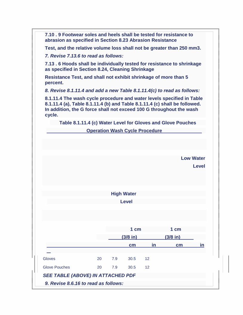
8. Revise 8.1.11.4 and add a new Table 8.1.11.4(c) to read as follows:
8.1.11.4 The wash cycle procedure and water levels specified in Table 8.1.11.4 (a), Table 8.1.11.4 (b) and Table 8.1.11.4 (c) shall be followed. In addition, the G force shall not exceed 100 G throughout the wash cycle.
Table 8.1.11.4 (c) Water Level for Gloves and Glove Pouches
Operation Wash Cycle Procedure
Low Water
Level
High Water
Level
1 cm 1 cm
(3/8 in) (3/8 in)
cm in cm in
Gloves 20 7.9 30.5 12
Glove Pouches 20 7.9 30.5 12
SEE TABLE (ABOVE) IN ATTACHED PDF
9. Revise 8.6.16 to read as follows:
8.6.16.11 The percent shrinkage of each hood face opening dimension shall be individually calculated, recorded, and reported.
8.6.16.12 The percent shrinkage of each of the three dimensions from the top of the hood to the marks along the basic plane shall be individually calculated, recorded, and reported.
8.6.16.13* The average percent shrinkage of all hood face opening dimensions for all specimens shall be calculated, recorded, and reported.
8.6.16.14* The average percent shrinkage of the three dimensions from the top of the hood to the marks along the basic plane for all specimens shall be calculated, recorded, and reported.
8.6.16.15 Pass or fail performance shall be based separately on the average percent shrinkage of the hood face opening dimensions and the average percent shrinkage of the three dimensions from the top of the hood to the marks along the basic plane for all specimens.
10. Replace existing 8.24.9.7 through 8.24.9.14 with the following:
8.24 . 9. 7 Each of the three dimensions from the top of the hood to the marks along the basic plane before and after laundering shall be recorded and reported.
8.24 . 9. 8 The percent shrinkage of each hood face opening dimension shall be individually calculated, recorded, and reported.
8.24 . 9. 9 The percent shrinkage of each of the three dimensions from the top of the hood to the marks along the basic plane shall be individually calculated, recorded, and reported.
8.24 . 9. 1 0 * The average percent shrinkage of all hood face opening dimensions for all specimens shall be calculated, recorded, and reported.
8.24 . 9. 1 1 * The average percent shrinkage of the three dimensions from the top of the hood to the marks along the basic plane for all specimens shall be calculated, recorded, and reported.
8.24 . 9. 1 2 Pass or fail performance shall be based separately on the average percent shrinkage of the hood face opening dimensions and the average percent shrinkage of the three dimensions from the top of the hood to the marks along the basic plane for all specimens.
11. Revise Paragraph 8.27.8.2 to read as follows:
8.27 . 8. 2 Samples for conditioning shall be in the form of a pouch as described in 8.1.16.

12. Revise Paragraph 8.28.8.2 to read as follows:
8.28 . 8. 2 Samples for conditioning shall be in the form of a pouch as described in 8.1.16.
13. Revise 8.40.4(4)* and add a new 8.40.4(5) to read as follows:
(4)* Calibration of the tiles shall be checked every 10 tests (50 test runs) or prior to each day of testing, whichever is the less frequent, to ensure that they are not being worn smooth or otherwise damaged.
(5) If the five consecutive test results of the measurements (for each configuration) show a systematic increase or decrease of more than 10% of the initial reading, then one or more further test runs shall be carried out until a sequence of five are obtained that do not show a systematic increase or decrease of greater than 10%.
14. Revise 8.72.5.2 and 8.72.5.4 to read as follows:
8.72 . 5. 2 While standing, each test subject shall grasp the cylinder so that the wrist creates a straight line with the hand. The elbow is against the side of the body, creating a right angle, throughout the duration of the test.
8.72 . 5. 4 Each test subject shall make five successive attempts to twist the cylinder in the appropriate direction exerting as much force as possible. The range of motion of the subject's wrist shall indicate the end of the twisting cycle. The average maximum force over the five attempts shall be the barehanded control value.
15. Renumber Annex items as follows:
A.5.1.9 in the Annex becomes A.5.1.7.3
A.5.1.10 in the Annex becomes A.5.1.7.4
A.5.1.11 in the Annex becomes A.5.1.7.5
16. Add new Annex items as follows:
A.8.6.16.13 This average should be based on a total of 12 values of percentage shrinkage with four values per specimen.
A.8.6.16.14 This average should be based on a total of 9 values of percentage shrinkage with three values per specimen.
17. Add new Annex Items to read as follows:
A.8.24.9.10 This average should be based on a total of 12 values of percentage shrinkage with four values per specimen.
A.8.24.9.11 This average should be based on a total of 9 values of percentage shrinkage with three values per specimen.
Issue Date: March 7, 2013
Effective Date: March 27, 2013
Additional Proposed Changes
File Name Description Approved
TIA1971-13-2.pdf NFPA 1971 TIA 13-2 Log #1092
Statement of Problem and Substantiation for Public Input
This public input originates from Tentative Interim Amendment No. 13-2, Log #1092 issued by the Standards Council on March 7, 2013 and per the NFPA Regs., needs to be reconsidered by the Technical Committee for the next edition of the Document. Submitter’s Substantiation: 1. The ASTM 2412 Standard needs to be updated to the current edition. 2, 3, and 14. The specific requirements for glove labels, which included type of fiber or material type, were inadvertently included in the generic list of requirements for labels on all ensemble elements. Since the majority of fabrics and materials used in construction of many of the ensemble elements contain multiple fibers and numerous blends, even attempting to include this level of detail on every product label would cause mass confusion. The issue becomes even more exacerbated by the minimum font sizes required on label text and by a garment specific label requirement, also included in the generic list, which mandates explicit component names as per the certification listing. This change provides the generic requirements for all labels, and then separates the specific ensemble element label requirements into subsets to avoid any interpretation issues. 4. The NFPA 1971 proposal (1971-46, Log CP-50) neglected to include the test method reference to Section 8.4 as well as the requirement for char length. NFPA 1971, 2013 edition references several flame resistance tests. It is important the standard references the correct flame resistance test and section number to insure the correct testing procedures are being followed. It was also the technical committee’s intent, based on historical data, to have the glove interface component evaluated for char length in addition to afterflame. 5. The NFPA 1971 proposal (1971-46, Log CP-50) neglected to include the test method reference to Section 8.4 as well as the requirement for char length. NFPA 1971, 2013 edition references several flame resistance tests. It is important the standard references the correct flame resistance test and section number to insure the correct testing procedures are being followed. It was also the technical committee’s intent, based on historical data, to have the glove extension component evaluated for char length in addition to afterflame. 6. This change brings this requirement in line with EN ISO 20345:2011. 7. The current laundering method described in Section 8.1.11 only accounts for water levels when laundering garments and CBRN Materials. The 2013 edition of NFPA 1971 now requires gloves and glove pouches to be laundered using Section 8.1.11 as a precondition. However a table for gloves and glove pouch water levels were not included. The water levels for the glove and glove pouch wash cycle needs to be specified in NFPA 1971, 2013 edition in order to allow for the front load wash machines to be properly programmed at the testing laboratories. The highest water levels currently in the standard were chosen to account for usage of both 35 lb and 50 lb capacity front-loading machines. The higher levels will also accommodate a full load of gloves/glove pouches and eliminate any risk associated with residual detergent. 8, 9, 15 and 16. Some changes made to the way the measurement of hood shrinkage were specified in cleaning shrinkage as part of the NFPA 1971-2013 revision would prevent any hood from being certified to the new requirements. There was also an inconsistency between how hood shrinkage was evaluated for both thermal and cleaning
shrinkage for the interpretation of test results that would lead to inconsistent determinations of compliance among testing laboratories. The proposed changes using the same approach established in the 2007 edition of NFPA 1971 for applying cleaning shrinkage criteria while clarifications have been made for interpretation of permitted shrinkage in both cleaning and thermal shrinkage test methods. 10. NFPA 1971, 2013 edition has sections for glove pouch construction, sections 8.1.15 and 8.1.16. Section 8.27.8.2, section for Liquid Penetration Resistance, should reference section 8.1.16 for moisture barrier testing. 11. NFPA 1971, 2013 edition has sections for glove pouch construction, sections 8.1.15 and 8.1.16. Section 8.28.8.2, section for Viral Penetration Resistance, should reference section 8.1.16 for moisture barrier testing. 12. The ISO 13287 standard does not provide criteria for the evaluation of systematic increase or decrease of values. Also, the current calibration language is not clear. 13. The test apparatus will be maxed out if the test subject uses their arm’s range of motion to perform this test. In order to achieve more accurate results it is important the test subject use their wrist’s range of motion to perform this test. Emergency Nature: This TIA seeks to correct errors and omissions that were overlooked during the Fall 2013 revision cycle process of NFPA 1971. Additionally, some parts of this TIA correct circumstances in which the standard could adversely impact a method or product that was inadvertently overlooked in the total revision process.
Submitter Information Verification
Submitter Full Name:
TC on FAE-SPF
Organization: NFPA Technical Committee on Structural and Proximity Fire Fighting Protective
Street Address:
City:
State:
Zip:
Submittal Date: Wed May 13 14:41:46 EDT 2015
Public Input No. 97-NFPA 1971-2015 [ Global Input ]
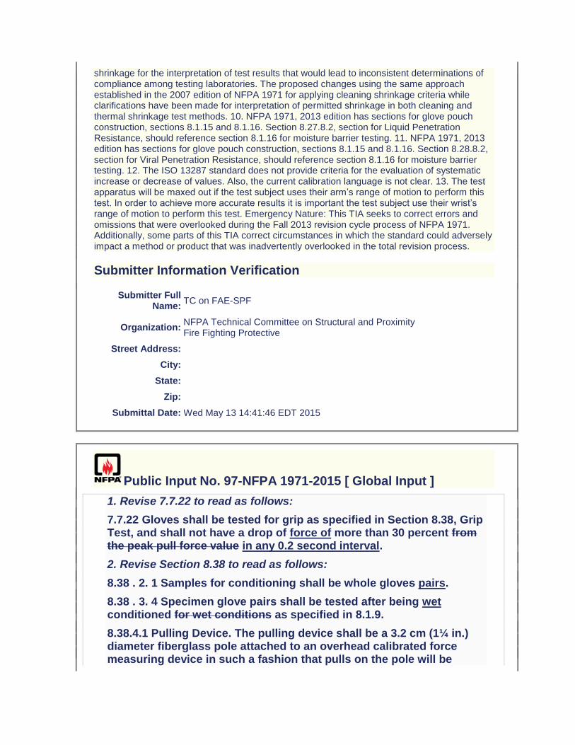
1. Revise 7.7.22 to read as follows:
7.7.22 Gloves shall be tested for grip as specified in Section 8.38, Grip Test, and shall not have a drop of force of more than 30 percent from the peak pull force value in any 0.2 second interval.
2. Revise Section 8.38 to read as follows:
8.38 . 2. 1 Samples for conditioning shall be whole gloves pairs.
8.38 . 3. 4 Specimen glove pairs shall be tested after being wet conditioned for wet conditions as specified in 8.1.9.
8.38.4.1 Pulling Device. The pulling device shall be a 3.2 cm (1¼ in.) diameter fiberglass pole attached to an overhead calibrated force measuring device in such a fashion that pulls on the pole will be

perpendicular to the ground and downward in direction. This pole shall be used until surface degradation occurs. The force measuring system shall provide a graphical plot of force-vs-time.
8.38 . 5. 1 Test subjects shall be selected so that their hand dimensions are as close as possible to the middle of the range for hand length and hand circumference as specified in Table 6.7.6.1 (a b) and Table 6.7.6.1(d) for size small and size large gloves. At least three test subjects shall be selected for both size small and size large.
8.38 . 5. 4 The test subject and the test subject’s hand shall be positioned as shown in Figure 8.38.5.4(a) and Figure
8.38.5.4(b), and as described below: shall then make three pulls on the pulling device with gloves with peak and minimum pull force values measured. Pulls shall be performed as described 8.38.5.4.1 through 8.38.5.4.6. The test subject shall extend the arms in front of the body at shoulder height to grab the pulling device for pulling vertically down from the ceiling.
Figure 8.38.5.4 (a) Position of test subject body, arms, and hands with respect to pole. Photo Courtesy Intertek
Testing Services, Used by Permission.
Figure 8.38.5.4 (b) Close-up of position of test subject hands on pole. Photo Courtesy Intertek Testing Services, Used by Permission.
8.38 . 5.4 . 1 The test subject shall stand facing the pole with feet shoulder width apart. with feet together, firmly planted on the ground, and knees slightly bent.
8.38 . 5.4 . 2 While wearing specimen gloves, the test subject shall grasp the pole with the bottom of the bottom hand at a height equal to the height of the subject. The stand shall be adjusted such that the cushioned bar is touching the test subject’s chest. The stand shall prevent the test subject’s forward movement during the pull.
8.38 . 5.4 . 3 The hands shall be stacked on each other and the thumbs shall not overlap the fingers. test subject shall stand in a comfortable pulling position with the arms bent at an angle of approximately 90 degrees and, in any case, the arms shall not be completely extended or touching the body.

8.38 . 5.4 . 4 The body shall be distanced from the pole so that the forearms are approaching vertical and in plane with the pole. test subject shall grasp the pulling device with hands next to each other. Thumbs shall not overlap the fingers.
8.38 . 5.4 . 5 The elbows shall be shoulder width apart, rotated neither fully in (arms parallel to the pole) nor fully out (arms perpendicular to the pole). test subject shall pull the rope or pole with as much pulling force as possible in a smooth, steady, swift, and non-jerking action. The test subject shall not bend the knees further or pull down with body weight during the pull.
8.38 . 5.4 . 6 The test subject shall continuously pull on the pulling device for a minimum of 5 seconds, 1/−0 seconds. The test subject shall continue to pull until the test facilitator observes a peak pulling force and instructs the test subject to end the pull.
8.38 . 5.5 The test subject shall pull the pole with as much pulling force as possible in a smooth, steady, swift, and non- jerking action for 5 1/-0 seconds. The test subject shall minimize forward or backward movement during the pull as much as possible. The test subject shall not bend the knees or pull down with body weight during the pull. The test subject shall continue to pull until the test facilitator instructs the test subject to end the pull at 5 1/-0 seconds.
8.38 . 5.6 The test subject shall repeat the pull described above for a total of three pulls.
8.38 . 6. 1 The peak pull force value for each individual pull shall be recorded and reported. Any drop in force of greater than 30% in any 0.2-second interval, as measured in the graphical plot of force-vs-time, shall be recorded and reported.
8.38 . 6.2 The minimum pull force value occurring after the peak pull force value shall be recorded and reported.
8.38 . 6.3 The percentage drop between the peak pull force value and the minimum pull force value shall be calculated, recorded, and reported.
8.38 . 7. 1 T h e individual percentage drop between the peak pull force value and the minimum pull force value shall be used to determine pass or fail performance. Any drop in force of greater than 30% in any 0.2-second interval shall constitute failing performance.
Issue Date: August 1, 2013
Effective Date: August 20, 2013
Additional Proposed Changes
File Name Description Approved
TIA1971-13-3.pdf NFPA 1971 TIA 13-3, Log 1100
Statement of Problem and Substantiation for Public Input
This public input originates from Tentative Interim Amendment No. 13-3, Log #1100 issued by the Standards Council on August 1, 2013 and per the NFPA Regs., needs to be reconsidered by the Technical Committee for the next edition of the Document. Submitter’s Substantiation: 1. The ASTM 2412 Standard needs to be updated to the current edition. 2, 3, and 14. The specific requirements for glove labels, which included type of fiber or material type, were inadvertently included in the generic list of requirements for labels on all ensemble elements. Since the majority of fabrics and materials used in construction of many of the ensemble elements contain multiple fibers and numerous blends, even attempting to include this level of detail on every product label would cause mass confusion. The issue becomes even more exacerbated by the minimum font sizes required on label text and by a garment specific label requirement, also included in the generic list, which mandates explicit component names as per the certification listing. This change provides the generic requirements for all labels, and then separates the specific ensemble element label requirements into subsets to avoid any interpretation issues. 4. The NFPA 1971 proposal (1971-46, Log CP-50) neglected to include the test method reference to Section 8.4 as well as the requirement for char length. NFPA 1971, 2013 edition references several flame resistance tests. It is important the standard references the correct flame resistance test and section number to insure the correct testing procedures are being followed. It was also the technical committee’s intent, based on historical data, to have the glove interface component evaluated for char length in addition to afterflame. 5. The NFPA 1971 proposal (1971-46, Log CP-50) neglected to include the test method reference to Section 8.4 as well as the requirement for char length. NFPA 1971, 2013 edition references several flame resistance tests. It is important the standard references the correct flame resistance test and section number to insure the correct testing procedures are being followed. It was also the technical committee’s intent, based on historical data, to have the glove extension component evaluated for char length in addition to afterflame. 6. This change brings this requirement in line with EN ISO 20345:2011. 7. The current laundering method described in Section 8.1.11 only accounts for water levels when laundering garments and CBRN Materials. The 2013 edition of NFPA 1971 now requires gloves and glove pouches to be laundered using Section 8.1.11 as a precondition. However a table for gloves and glove pouch water levels were not included. The water levels for the glove and glove pouch wash cycle needs to be specified in NFPA 1971, 2013 edition in order to allow for the front load wash machines to be properly programmed at the testing laboratories. The highest water levels currently in the standard were chosen to account for usage of both 35 lb and 50 lb capacity front-loading machines. The higher levels will also accommodate a full load of gloves/glove pouches and eliminate any risk associated with residual detergent. 8, 9, 15 and 16. Some changes made to the way the measurement of hood shrinkage were specified in cleaning shrinkage as part of the NFPA 1971-2013 revision would prevent any hood from being certified to the new requirements. There was also an inconsistency between how hood shrinkage was evaluated for both thermal and cleaning shrinkage for the interpretation of test results that would lead to inconsistent determinations of compliance among testing laboratories. The proposed changes using the same approach established in the 2007 edition of NFPA 1971 for applying cleaning shrinkage criteria while clarifications have been made for interpretation of permitted shrinkage in both cleaning and thermal shrinkage test methods. 10. NFPA 1971, 2013 edition has sections for glove pouch construction, sections 8.1.15 and 8.1.16. Section 8.27.8.2, section for Liquid Penetration Resistance, should reference section 8.1.16 for moisture barrier testing. 11. NFPA 1971, 2013
edition has sections for glove pouch construction, sections 8.1.15 and 8.1.16. Section 8.28.8.2, section for Viral Penetration Resistance, should reference section 8.1.16 for moisture barrier testing. 12. The ISO 13287 standard does not provide criteria for the evaluation of systematic increase or decrease of values. Also, the current calibration language is not clear. 13. The test apparatus will be maxed out if the test subject uses their arm’s range of motion to perform this test. In order to achieve more accurate results it is important the test subject use their wrist’s range of motion to perform this test. Emergency Nature: This TIA seeks to correct errors and omissions that were overlooked during the Fall 2013 revision cycle process of NFPA 1971. Additionally, some parts of this TIA correct circumstances in which the standard could adversely impact a method or product that was inadvertently overlooked in the total revision process.
Submitter Information Verification
Submitter Full Name:
TC on FAE-SPF
Organization: NFPA Technical Committee on Structural and Proximity Fire Fighting Protective
Street Address:
City:
State:
Zip:
Submittal Date: Wed May 13 14:54:51 EDT 2015
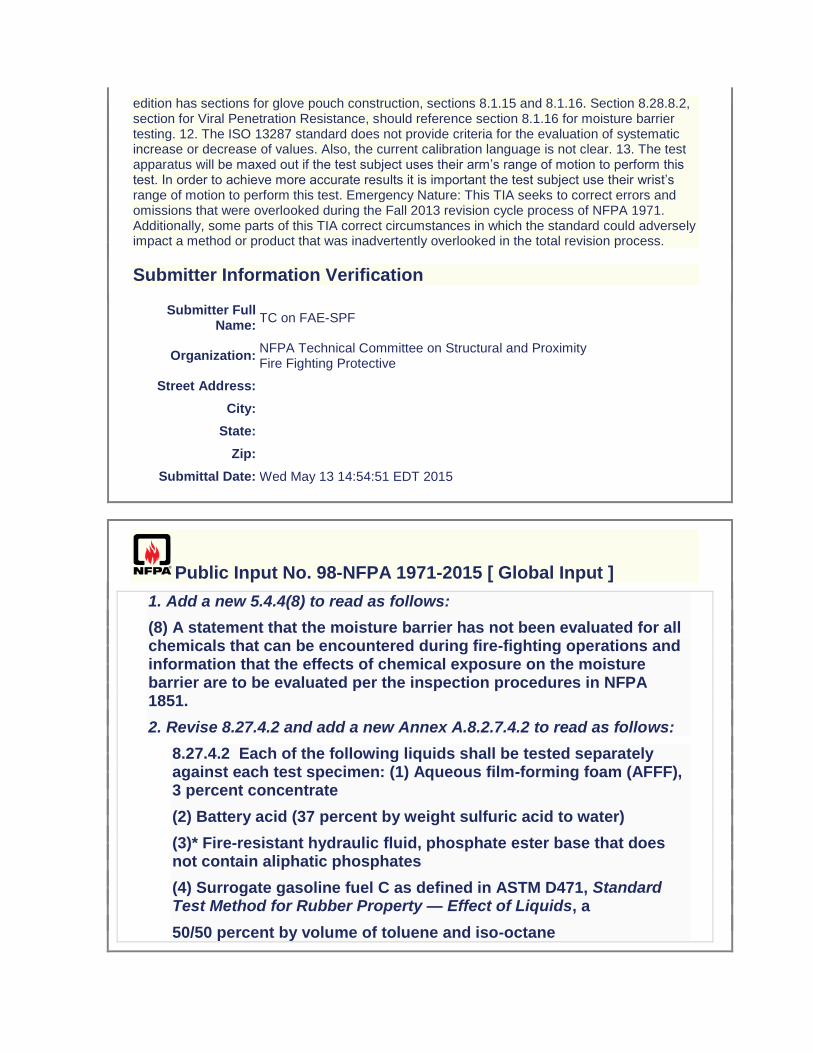
Public Input No. 98-NFPA 1971-2015 [ Global Input ]
1. Add a new 5.4.4(8) to read as follows:
(8) A statement that the moisture barrier has not been evaluated for all chemicals that can be encountered during fire-fighting operations and information that the effects of chemical exposure on the moisture barrier are to be evaluated per the inspection procedures in NFPA 1851.
2. Revise 8.27.4.2 and add a new Annex A.8.2.7.4.2 to read as follows:
8.27.4.2 Each of the following liquids shall be tested separately against each test specimen: (1) Aqueous film-forming foam (AFFF), 3 percent concentrate
(2) Battery acid (37 percent by weight sulfuric acid to water)
(3)* Fire-resistant hydraulic fluid, phosphate ester base that does not contain aliphatic phosphates
(4) Surrogate gasoline fuel C as defined in ASTM D471, Standard Test Method for Rubber Property — Effect of Liquids, a
50/50 percent by volume of toluene and iso-octane
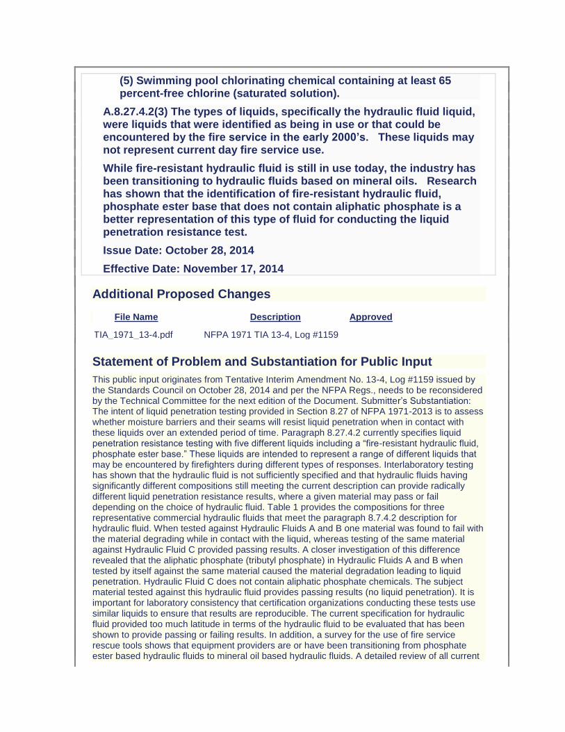
(5) Swimming pool chlorinating chemical containing at least 65 percent-free chlorine (saturated solution).
A.8.27.4.2(3) The types of liquids, specifically the hydraulic fluid liquid, were liquids that were identified as being in use or that could be encountered by the fire service in the early 2000’s. These liquids may not represent current day fire service use.
While fire-resistant hydraulic fluid is still in use today, the industry has been transitioning to hydraulic fluids based on mineral oils. Research has shown that the identification of fire-resistant hydraulic fluid, phosphate ester base that does not contain aliphatic phosphate is a better representation of this type of fluid for conducting the liquid penetration resistance test.
Issue Date: October 28, 2014
Effective Date: November 17, 2014
Additional Proposed Changes
File Name Description Approved
TIA_1971_13-4.pdf NFPA 1971 TIA 13-4, Log #1159
Statement of Problem and Substantiation for Public Input
This public input originates from Tentative Interim Amendment No. 13-4, Log #1159 issued by the Standards Council on October 28, 2014 and per the NFPA Regs., needs to be reconsidered by the Technical Committee for the next edition of the Document. Submitter’s Substantiation: The intent of liquid penetration testing provided in Section 8.27 of NFPA 1971-2013 is to assess whether moisture barriers and their seams will resist liquid penetration when in contact with these liquids over an extended period of time. Paragraph 8.27.4.2 currently specifies liquid penetration resistance testing with five different liquids including a “fire-resistant hydraulic fluid, phosphate ester base.” These liquids are intended to represent a range of different liquids that may be encountered by firefighters during different types of responses. Interlaboratory testing has shown that the hydraulic fluid is not sufficiently specified and that hydraulic fluids having significantly different compositions still meeting the current description can provide radically different liquid penetration resistance results, where a given material may pass or fail depending on the choice of hydraulic fluid. Table 1 provides the compositions for three representative commercial hydraulic fluids that meet the paragraph 8.7.4.2 description for hydraulic fluid. When tested against Hydraulic Fluids A and B one material was found to fail with the material degrading while in contact with the liquid, whereas testing of the same material against Hydraulic Fluid C provided passing results. A closer investigation of this difference revealed that the aliphatic phosphate (tributyl phosphate) in Hydraulic Fluids A and B when tested by itself against the same material caused the material degradation leading to liquid penetration. Hydraulic Fluid C does not contain aliphatic phosphate chemicals. The subject material tested against this hydraulic fluid provides passing results (no liquid penetration). It is important for laboratory consistency that certification organizations conducting these tests use similar liquids to ensure that results are reproducible. The current specification for hydraulic fluid provided too much latitude in terms of the hydraulic fluid to be evaluated that has been shown to provide passing or failing results. In addition, a survey for the use of fire service rescue tools shows that equipment providers are or have been transitioning from phosphate ester based hydraulic fluids to mineral oil based hydraulic fluids. A detailed review of all current
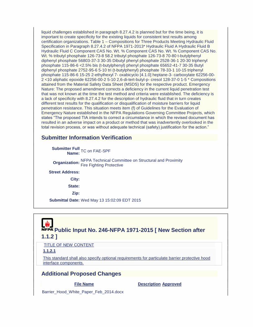
liquid challenges established in paragraph 8.27.4.2 is planned but for the time being, it is important to create specificity for the existing liquids for consistent test results among certification organizations. Table 1 – Compositions for Three Products Meeting Hydraulic Fluid Specification in Paragraph 8.27.4.2 of NFPA 1971-2013* Hydraulic Fluid A Hydraulic Fluid B Hydraulic Fluid C Component CAS No. Wt. % Component CAS No. Wt. % Component CAS No. Wt. % tributyl phosphate 126-73-8 58.2 tributyl phosphate 126-73-8 70-80 t-butylphenyl diphenyl phosphate 56803-37-3 30-35 Dibutyl phenyl phosphate 2528-36-1 20-30 triphenyl phosphate 115-86-6 <2.5% bis (t-butylphenyl) phenyl phosphate 65652-41-7 30-35 Butyl diphenyl phosphate 2752-95-6 5-10 tri (t-butylphenyl) phosphate 78-33-1 10-15 triphenyl phosphate 115-86-6 15-25 2-ethylhexyl 7- oxabicyclo [4.1.0] heptane-3- carboxylate 62256-00-2 <10 aliphatic epoxide 62256-00-2 5-10 2,6-di-tert-butyl-p- cresol 128-37-0 1-5 * Compositions attained from the Material Safety Data Sheet (MSDS) for the respective product. Emergency Nature: The proposed amendment corrects a deficiency in the current liquid penetration test that was not known at the time the test method and criteria were established. The deficiency is a lack of specificity with 8.27.4.2 for the description of hydraulic fluid that in turn creates different test results for the qualification or disqualification of moisture barriers for liquid penetration resistance. This situation meets item (f) of Guidelines for the Evaluation of Emergency Nature established in the NFPA Regulations Governing Committee Projects, which states “The proposed TIA intends to correct a circumstance in which the revised document has resulted in an adverse impact on a product or method that was inadvertently overlooked in the total revision process, or was without adequate technical (safety) justification for the action.”
Submitter Information Verification
Submitter Full Name:
TC on FAE-SPF
Organization: NFPA Technical Committee on Structural and Proximity Fire Fighting Protective
Street Address:
City:
State:
Zip:
Submittal Date: Wed May 13 15:02:09 EDT 2015
Public Input No. 246-NFPA 1971-2015 [ New Section after 1.1.2 ]
TITLE OF NEW CONTENT
1.1.2.1
This standard shall also specify optional requirements for particulate barrier protective hood interface components.
Additional Proposed Changes
File Name Description Approved
Barrier_Hood_White_Paper_Feb_2014.docx
Statement of Problem and Substantiation for Public Input
Protective hoods currently do not require any form of a barrier layer and the majority of protective hoods in the market place are fabricated of two or more layers of an open knit that readily allows smoke and contaminant particles to pass through the hood materials and deposit on the wearer’s skin. Optional requirements for a hood are proposed that define a barrier that limits the passage of particulates as addressed by both design and performance requirements. This input proposes a modification in the scope to address requirements for an optional particular barrier hood interface component. A white paper on this topic is attached.
Related Public Inputs for This Document
Related Input Relationship
Public Input No. 242-NFPA 1971-2015 [Section No. 6.18]
Public Input No. 247-NFPA 1971-2015 [Section No. 7.14]
Public Input No. 250-NFPA 1971-2015 [New Section after 8.74]
Public Input No. 252-NFPA 1971-2015 [Section No. 8.33]
Submitter Information Verification
Submitter Full Name: JEFFREY STULL
Organization: INTERNATIONAL PERSONNEL PROTECTION, INC.
Street Address:
City:
State:
Zip:
Submittal Date: Mon Jul 06 15:17:15 EDT 2015
Public Input No. 39-NFPA 1971-2014 [ Chapter 2 ]
Chapter 2 Referenced Publications
2.1 General.
The documents or portions thereof listed in this chapter are referenced within this standard and shall be considered part of the requirements of this document.
2.2 NFPA Publications.
National Fire Protection Association, 1 Batterymarch Park, Quincy, MA 02169-7471.
NFPA 1500, Standard on Fire Department Occupational Safety and Health Program, 2013 edition.
NFPA 1981, Standard on Open-Circuit Self-Contained Breathing Apparatus (SCBA) for Emergency Services,2007 edition 2013.
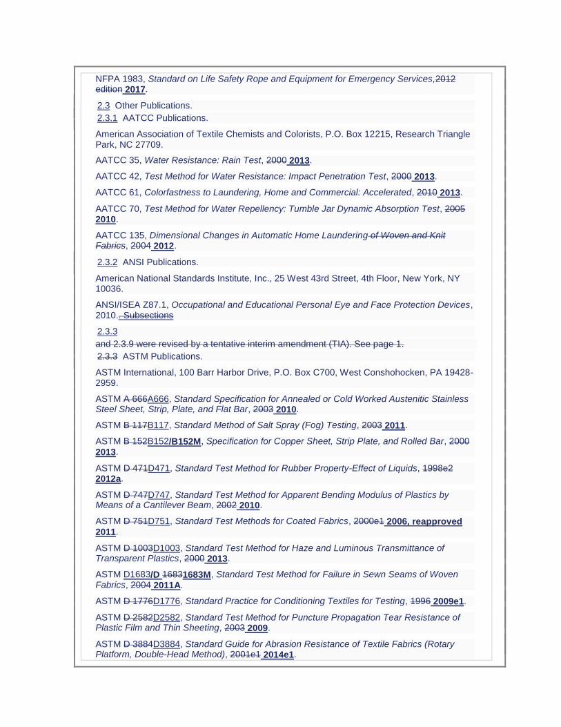
NFPA 1983, Standard on Life Safety Rope and Equipment for Emergency Services,2012 edition 2017.
2.3 Other Publications.
2.3.1 AATCC Publications.
American Association of Textile Chemists and Colorists, P.O. Box 12215, Research Triangle Park, NC 27709.
AATCC 35, Water Resistance: Rain Test, 2000 2013.
AATCC 42, Test Method for Water Resistance: Impact Penetration Test, 2000 2013.
AATCC 61, Colorfastness to Laundering, Home and Commercial: Accelerated, 2010 2013.
AATCC 70, Test Method for Water Repellency: Tumble Jar Dynamic Absorption Test, 2005 2010.
AATCC 135, Dimensional Changes in Automatic Home Laundering of Woven and Knit Fabrics, 2004 2012.
2.3.2 ANSI Publications.
American National Standards Institute, Inc., 25 West 43rd Street, 4th Floor, New York, NY 10036.
ANSI/ISEA Z87.1, Occupational and Educational Personal Eye and Face Protection Devices, 2010.. Subsections
2.3.3
and 2.3.9 were revised by a tentative interim amendment (TIA). See page 1.
2.3.3 ASTM Publications.
ASTM International, 100 Barr Harbor Drive, P.O. Box C700, West Conshohocken, PA 19428-2959.
ASTM A 666A666, Standard Specification for Annealed or Cold Worked Austenitic Stainless Steel Sheet, Strip, Plate, and Flat Bar, 2003 2010.
ASTM B 117B117, Standard Method of Salt Spray (Fog) Testing, 2003 2011.
ASTM B 152B152/B152M, Specification for Copper Sheet, Strip Plate, and Rolled Bar, 2000
2013.
ASTM D 471D471, Standard Test Method for Rubber Property-Effect of Liquids, 1998e2 2012a.
ASTM D 747D747, Standard Test Method for Apparent Bending Modulus of Plastics by Means of a Cantilever Beam, 2002 2010.
ASTM D 751D751, Standard Test Methods for Coated Fabrics, 2000e1 2006, reapproved 2011.
ASTM D 1003D1003, Standard Test Method for Haze and Luminous Transmittance of Transparent Plastics, 2000 2013.
ASTM D1683/D 16831683M, Standard Test Method for Failure in Sewn Seams of Woven Fabrics, 2004 2011A.
ASTM D 1776D1776, Standard Practice for Conditioning Textiles for Testing, 1996 2009e1.
ASTM D 2582D2582, Standard Test Method for Puncture Propagation Tear Resistance of Plastic Film and Thin Sheeting, 2003 2009.
ASTM D 3884D3884, Standard Guide for Abrasion Resistance of Textile Fabrics (Rotary Platform, Double-Head Method), 2001e1 2014e1.

ASTM D 3940D3940, Standard Test Method for Bursting Strength (Load) and Elongation of Sewn Seams of Knit or Woven Stretch Textile Fabrics, 1983, (withdrawn).
ASTM D 4157D4157, Standard Test Method for Abrasion Resistance of Textile Fabrics (Oscillatory Cylinder Method), 2002 2013.
ASTM D 4966D4966, Standard Test Method for Abrasion Resistance of Textile Fabrics, 1998 (2004) 2013 e1.
ASTM D 5034D5034, Standard Method for Breaking Strength and Elongation of Textile Fabrics (Grab Test), 1995 (2001) 2009, reapproved 2013.
ASTM D 5169D5169, Standard Test Method for Shear Strength (Dynamic Method) of Hook and Loop Touch Fasteners, 1998 (, reapproved 2010).
ASTM D 5170D5170, Standard Test Method for Peel Strength (“T” Method) of Hook and Loop Touch Fasteners, 1998 (, reapproved 2010).
ASTM D 5587D5587, Standard Test Method for the Tearing Strength of Fabrics by the Trapezoidal Procedure, 2005 2014.
ASTM D 6413D6413/D6413M, Standard Test Method for Flame Resistance of Textiles (Vertical Test), 1999 2013B.
ASTM D 6775D6775, Standard Test Method for Breaking Strength and Elongation of Textile Webbing, Tape and Braided Material, 2002e1 2013.
ASTM D 6797D6797, Standard Test Method for Bursting Strength of Fabrics Constant-Rate-of-Extension (CRE) Ball Burst Test, 2007, reapproved 2013.
ASTM E 809E809, Standard Practice for Measuring Photometric Characteristics of Retroreflectors, 2002 2008, reapproved 2013.
ASTM E 991E991, Standard Practice for Color Measurement of Fluorescent Specimens, 1998 2011.
ASTM E 1164E1164, Standard Practice for Obtaining Spectrometric Data for Object Color Evaluation, 2002 2012.
ASTM E 2152E2152, Standard Practice for Computing the Colors of Fluorescent Objects from Bispectral Photometric Data, 2001 2012.
ASTM E 2153E2153, Standard Practice for Obtaining Bispectral Photometric Data for Evaluation of Fluorescent Color, 2001; Edition 3, reapproved 2011.
ASTM F 392F392/F392M, Standard Test Method for Flex Durability of Flexible Barrier Materials, 1993 (2004) 2011.
ASTM F 903F903, Standard Test Method for Resistance of Protective Clothing Materials to Penetration by Liquids, 2003 (2004) 2010.
ASTM F 1060F1060, Standard Test Method for Thermal Protective Performance of Materials for Protective Clothing for Hot Surface Contact, 2005 2008.
ASTM F 1342F1342/F1342M, Standard Test Method for Protective Clothing Material Resistance to Puncture, 2005 2013 E1.
ASTM F 1359F1359/F1359M, Standard Practice for Evaluating the Liquid-Tight Integrity of Chemical Protective Clothing, 1999a (2004) 2013.
ASTM F 1671F1671/F1671M, Standard Test Method for Resistance of Materials Used in
Protective Clothing to Penetration by Blood-Borne Pathogens Using Phi-X-174 Bacteriophage as a Test System, 2003 2013.
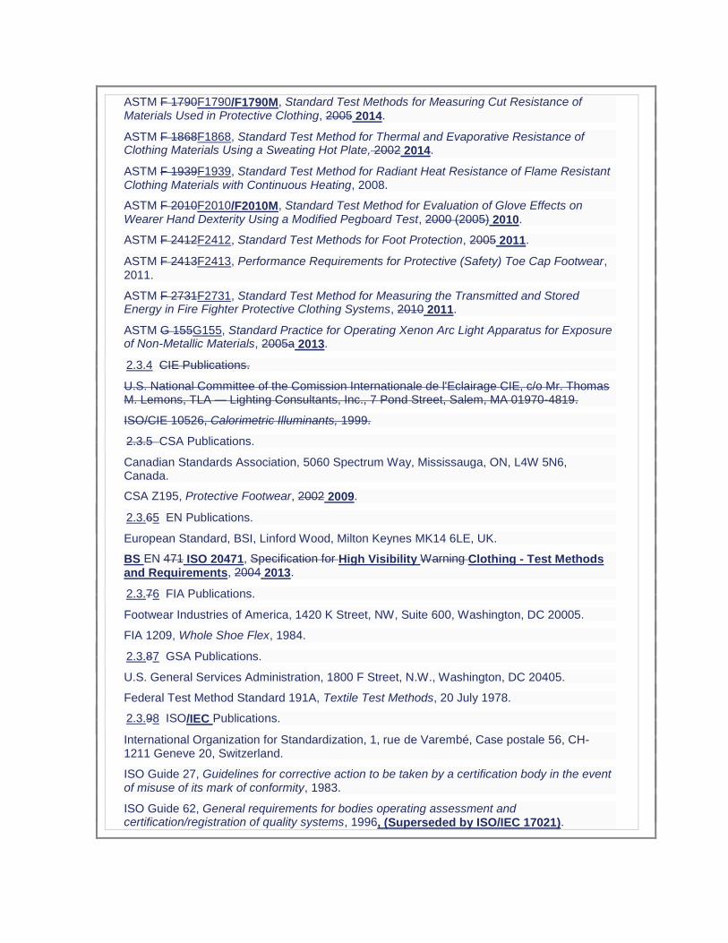
ASTM F 1790F1790/F1790M, Standard Test Methods for Measuring Cut Resistance of Materials Used in Protective Clothing, 2005 2014.
ASTM F 1868F1868, Standard Test Method for Thermal and Evaporative Resistance of Clothing Materials Using a Sweating Hot Plate, 2002 2014.
ASTM F 1939F1939, Standard Test Method for Radiant Heat Resistance of Flame Resistant Clothing Materials with Continuous Heating, 2008.
ASTM F 2010F2010/F2010M, Standard Test Method for Evaluation of Glove Effects on Wearer Hand Dexterity Using a Modified Pegboard Test, 2000 (2005) 2010.
ASTM F 2412F2412, Standard Test Methods for Foot Protection, 2005 2011.
ASTM F 2413F2413, Performance Requirements for Protective (Safety) Toe Cap Footwear, 2011.
ASTM F 2731F2731, Standard Test Method for Measuring the Transmitted and Stored Energy in Fire Fighter Protective Clothing Systems, 2010 2011.
ASTM G 155G155, Standard Practice for Operating Xenon Arc Light Apparatus for Exposure of Non-Metallic Materials, 2005a 2013.
2.3.4 CIE Publications.
U.S. National Committee of the Comission Internationale de l'Eclairage CIE, c/o Mr. Thomas M. Lemons, TLA — Lighting Consultants, Inc., 7 Pond Street, Salem, MA 01970-4819.
ISO/CIE 10526, Calorimetric Illuminants, 1999.
2.3.5 CSA Publications.
Canadian Standards Association, 5060 Spectrum Way, Mississauga, ON, L4W 5N6, Canada.
CSA Z195, Protective Footwear, 2002 2009.
2.3.65 EN Publications.
European Standard, BSI, Linford Wood, Milton Keynes MK14 6LE, UK.
BS EN 471 ISO 20471, Specification for High Visibility Warning Clothing - Test Methods and Requirements, 2004 2013.
2.3.76 FIA Publications.
Footwear Industries of America, 1420 K Street, NW, Suite 600, Washington, DC 20005.
FIA 1209, Whole Shoe Flex, 1984.
2.3.87 GSA Publications.
U.S. General Services Administration, 1800 F Street, N.W., Washington, DC 20405.
Federal Test Method Standard 191A, Textile Test Methods, 20 July 1978.
2.3.98 ISO/IEC Publications.
International Organization for Standardization, 1, rue de Varembé, Case postale 56, CH-1211 Geneve 20, Switzerland.
ISO Guide 27, Guidelines for corrective action to be taken by a certification body in the event of misuse of its mark of conformity, 1983.
ISO Guide 62, General requirements for bodies operating assessment and certification/registration of quality systems, 1996, (Superseded by ISO/IEC 17021).
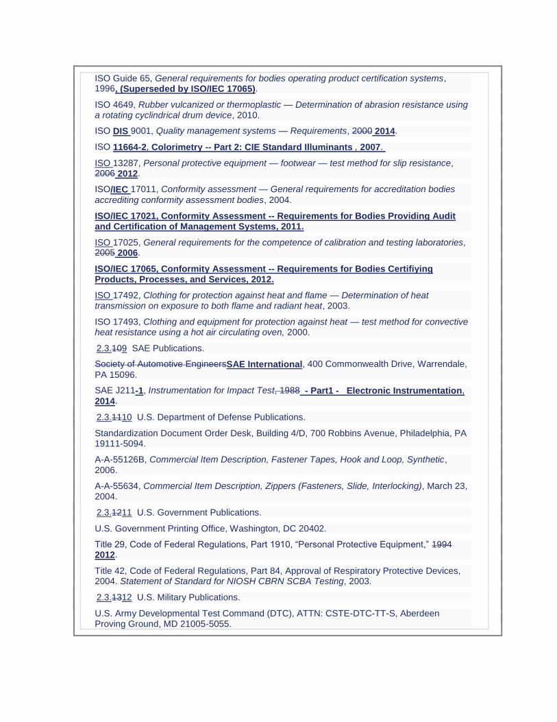
ISO Guide 65, General requirements for bodies operating product certification systems, 1996, (Superseded by ISO/IEC 17065).
ISO 4649, Rubber vulcanized or thermoplastic — Determination of abrasion resistance using a rotating cyclindrical drum device, 2010.
ISO DIS 9001, Quality management systems — Requirements, 2000 2014.
ISO 11664-2, Colorimetry -- Part 2: CIE Standard Illuminants , 2007.
ISO 13287, Personal protective equipment — footwear — test method for slip resistance, 2006 2012.
ISO/IEC 17011, Conformity assessment — General requirements for accreditation bodies
accrediting conformity assessment bodies, 2004.
ISO/IEC 17021, Conformity Assessment -- Requirements for Bodies Providing Audit and Certification of Management Systems, 2011.
ISO 17025, General requirements for the competence of calibration and testing laboratories, 2005 2006.
ISO/IEC 17065, Conformity Assessment -- Requirements for Bodies Certifiying Products, Processes, and Services, 2012.
ISO 17492, Clothing for protection against heat and flame — Determination of heat transmission on exposure to both flame and radiant heat, 2003.
ISO 17493, Clothing and equipment for protection against heat — test method for convective heat resistance using a hot air circulating oven, 2000.
2.3.109 SAE Publications.
Society of Automotive EngineersSAE International, 400 Commonwealth Drive, Warrendale,
PA 15096.
SAE J211-1, Instrumentation for Impact Test, 1988 - Part1 - Electronic Instrumentation,
2014.
2.3.1110 U.S. Department of Defense Publications.
Standardization Document Order Desk, Building 4/D, 700 Robbins Avenue, Philadelphia, PA 19111-5094.
A-A-55126B, Commercial Item Description, Fastener Tapes, Hook and Loop, Synthetic, 2006.
A-A-55634, Commercial Item Description, Zippers (Fasteners, Slide, Interlocking), March 23, 2004.
2.3.1211 U.S. Government Publications.
U.S. Government Printing Office, Washington, DC 20402.
Title 29, Code of Federal Regulations, Part 1910, “Personal Protective Equipment,” 1994 2012.
Title 42, Code of Federal Regulations, Part 84, Approval of Respiratory Protective Devices, 2004. Statement of Standard for NIOSH CBRN SCBA Testing, 2003.
2.3.1312 U.S. Military Publications.
U.S. Army Developmental Test Command (DTC), ATTN: CSTE-DTC-TT-S, Aberdeen Proving Ground, MD 21005-5055.
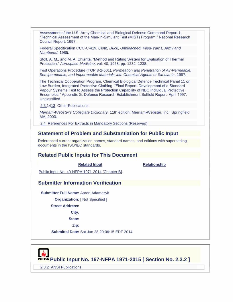
Assessment of the U.S. Army Chemical and Biological Defense Command Report 1, “Technical Assessment of the Man-In-Simulant Test (MIST) Program,” National Research Council Report, 1997.
Federal Specification CCC-C-419, Cloth, Duck, Unbleached, Plied-Yarns, Army and Numbered, 1985.
Stoll, A. M., and M. A. Chianta, “Method and Rating System for Evaluation of Thermal Protection,” Aerospace Medicine, vol. 40, 1968, pp. 1232–1238.
Test Operations Procedure (TOP 8-2-501), Permeation and Penetration of Air-Permeable, Semipermeable, and Impermeable Materials with Chemical Agents or Simulants, 1997.
The Technical Cooperation Program, Chemical Biological Defence Technical Panel 11 on Low Burden, Integrated Protective Clothing, “Final Report: Development of a Standard Vapour Systems Test to Assess the Protection Capability of NBC Individual Protective Ensembles,” Appendix G, Defence Research Establishment Suffield Report, April 1997, Unclassified.
2.3.1413 Other Publications.
Merriam-Webster's Collegiate Dictionary, 11th edition, Merriam-Webster, Inc., Springfield, MA, 2003.
2.4 References For Extracts in Mandatory Sections (Reserved)
Statement of Problem and Substantiation for Public Input
Referenced current organization names, standard names, and editions with superseding documents in the ISO/IEC standards.
Related Public Inputs for This Document
Related Input Relationship
Public Input No. 40-NFPA 1971-2014 [Chapter B]
Submitter Information Verification
Submitter Full Name: Aaron Adamczyk
Organization: [ Not Specified ]
Street Address:
City:
State:
Zip:
Submittal Date: Sat Jun 28 20:06:15 EDT 2014
Public Input No. 167-NFPA 1971-2015 [ Section No. 2.3.2 ]
2.3.2 ANSI Publications.
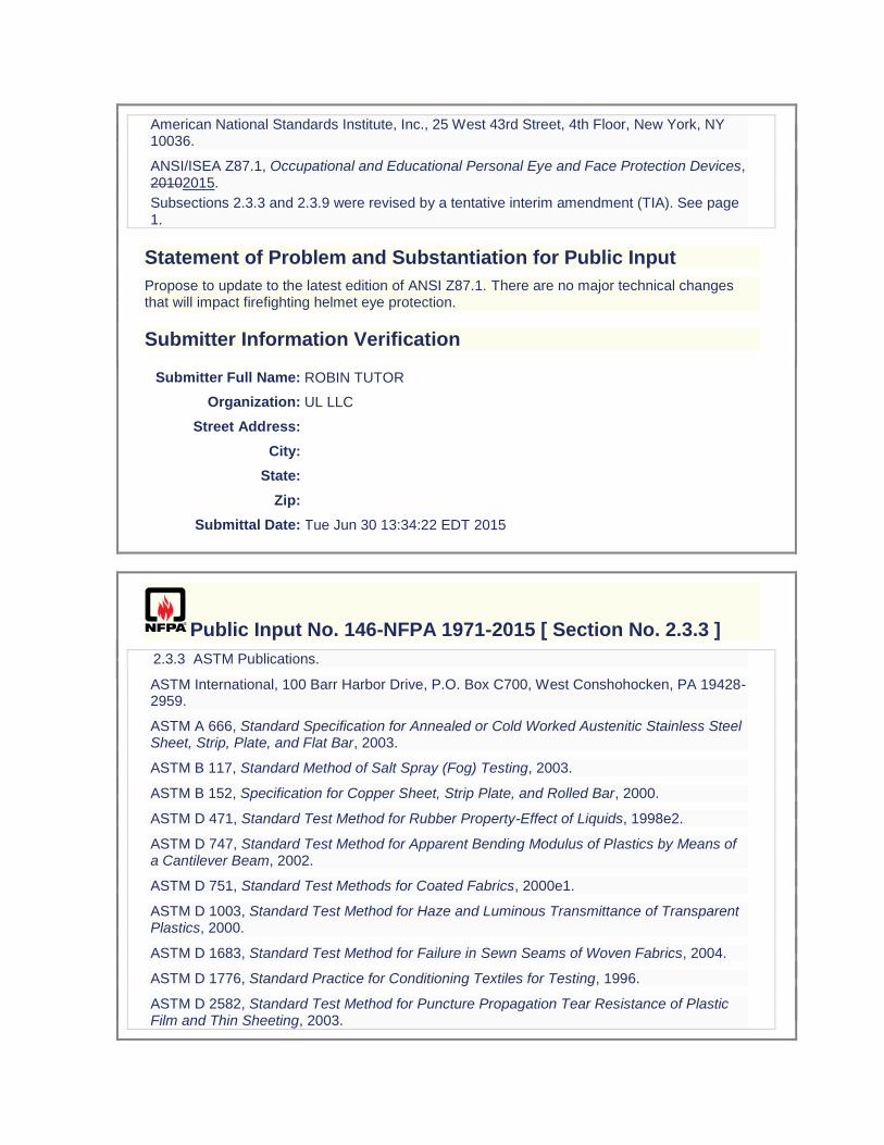
American National Standards Institute, Inc., 25 West 43rd Street, 4th Floor, New York, NY 10036.
ANSI/ISEA Z87.1, Occupational and Educational Personal Eye and Face Protection Devices, 20102015.
.
Subsections 2.3.3 and 2.3.9 were revised by a tentative interim amendment (TIA). See page 1.
Statement of Problem and Substantiation for Public Input
Propose to update to the latest edition of ANSI Z87.1. There are no major technical changes that will impact firefighting helmet eye protection.
Submitter Information Verification
Submitter Full Name: ROBIN TUTOR
Organization: UL LLC
Street Address:
City:
State:
Zip:
Submittal Date: Tue Jun 30 13:34:22 EDT 2015
Public Input No. 146-NFPA 1971-2015 [ Section No. 2.3.3 ]
2.3.3 ASTM Publications.
ASTM International, 100 Barr Harbor Drive, P.O. Box C700, West Conshohocken, PA 19428-2959.
ASTM A 666, Standard Specification for Annealed or Cold Worked Austenitic Stainless Steel Sheet, Strip, Plate, and Flat Bar, 2003.
ASTM B 117, Standard Method of Salt Spray (Fog) Testing, 2003.
ASTM B 152, Specification for Copper Sheet, Strip Plate, and Rolled Bar, 2000.
ASTM D 471, Standard Test Method for Rubber Property-Effect of Liquids, 1998e2.
ASTM D 747, Standard Test Method for Apparent Bending Modulus of Plastics by Means of a Cantilever Beam, 2002.
ASTM D 751, Standard Test Methods for Coated Fabrics, 2000e1.
ASTM D 1003, Standard Test Method for Haze and Luminous Transmittance of Transparent Plastics, 2000.
ASTM D 1683, Standard Test Method for Failure in Sewn Seams of Woven Fabrics, 2004.
ASTM D 1776, Standard Practice for Conditioning Textiles for Testing, 1996.
ASTM D 2582, Standard Test Method for Puncture Propagation Tear Resistance of Plastic Film and Thin Sheeting, 2003.
ASTM D 3884, Standard Guide for Abrasion Resistance of Textile Fabrics (Rotary Platform, Double-Head Method), 2001e1.
ASTM D 3940, Standard Test Method for Bursting Strength (Load) and Elongation of Sewn Seams of Knit or Woven Stretch Textile Fabrics, 1983.
ASTM D 4157, Standard Test Method for Abrasion Resistance of Textile Fabrics (Oscillatory Cylinder Method), 2002.
ASTM D 4966, Standard Test Method for Abrasion Resistance of Textile Fabrics, 1998 (2004).
ASTM D 5034, Standard Method for Breaking Strength and Elongation of Textile Fabrics (Grab Test), 1995 (2001).
ASTM D 5169, Standard Test Method for Shear Strength (Dynamic Method) of Hook and Loop Touch Fasteners, 1998 (2010).
ASTM D 5170, Standard Test Method for Peel Strength (“T” Method) of Hook and Loop Touch Fasteners, 1998 (2010).
ASTM D 5587, Standard Test Method for the Tearing Strength of Fabrics by the Trapezoidal Procedure, 2005.
ASTM D 6413, Standard Test Method for Flame Resistance of Textiles (Vertical Test), 1999.
ASTM D 6775, Standard Test Method for Breaking Strength and Elongation of Textile Webbing, Tape and Braided Material, 2002e1.
ASTM D 6797, Standard Test Method for Bursting Strength of Fabrics Constant-Rate-of-Extension (CRE) Ball Burst Test, 2007.
ASTM E 809, Standard Practice for Measuring Photometric Characteristics of Retroreflectors, 2002.
ASTM E 991, Standard Practice for Color Measurement of Fluorescent Specimens, 1998.
ASTM E 1164, Standard Practice for Obtaining Spectrometric Data for Object Color Evaluation, 2002.
ASTM E 2152, Standard Practice for Computing the Colors of Fluorescent Objects from Bispectral Photometric Data, 2001.
ASTM E 2153, Standard Practice for Obtaining Bispectral Photometric Data for Evaluation of Fluorescent Color, 2001; Edition 3.
ASTM F 392, Standard Test Method for Flex Durability of Flexible Barrier Materials, 1993 (2004).
ASTM F 903, Standard Test Method for Resistance of Protective Clothing Materials to Penetration by Liquids, 2003 (2004).
ASTM F 1060, Standard Test Method for Thermal Protective Performance of Materials for Protective Clothing for Hot Surface Contact, 2005.
ASTM F 1342, Standard Test Method for Protective Clothing Material Resistance to Puncture, 2005.
ASTM F 1359, Standard Practice for Evaluating the Liquid-Tight Integrity of Chemical Protective Clothing, 1999a (2004).
ASTM F 1671, Standard Test Method for Resistance of Materials Used in Protective Clothing to Penetration by Blood-Borne Pathogens Using Phi-X-174 Bacteriophage as a Test System, 2003.
ASTM F 1790, Standard Test Methods for Measuring Cut Resistance of Materials Used in Protective Clothing, 2005.
ASTM F 1868, Standard Test Method for Thermal and Evaporative Resistance of Clothing Materials Using a Sweating Hot Plate, 2002.
ASTM F 1939, Standard Test Method for Radiant Heat Resistance of Flame Resistant Clothing Materials with Continuous Heating, 2008.
ASTM F 2010, Standard Test Method for Evaluation of Glove Effects on Wearer Hand Dexterity Using a Modified Pegboard Test, 2000 (2005).
ASTM F 2412, Standard Test Methods for Foot Protection, 2005.
ASTM F 2413, Performance Requirements for Protective (Safety) Toe Cap Footwear, 2011.
ASTM F 2731, Standard Test Method for Measuring the Transmitted and Stored Energy in Fire Fighter Protective Clothing Systems, 2010.
ASTM F 2961, Standard Test Method for Characterizing Gripping Performance of Gloves Using a Torque Meter, 2015.
ASTM G 155, Standard Practice for Operating Xenon Arc Light Apparatus for Exposure of Non-Metallic Materials, 2005a.
Statement of Problem and Substantiation for Public Input
Referencing the ASTM Torque test method in Chapter 2 and in Chapter 8 in place of the existing language. The ASTM version is approximately the same method as currently used except with the following improvements: 1.) 3 test subjects are used per size instead of 1 (this provides a larger test subject pool/more information, is reduces fatigue issues, and is consistent with other human subject glove tests such as Hand Function, Tool, and Grip tests) 2.) The issue of fatigue is addressed (beyond just increasing the number of subjects) 3.) More test details and photos are provided
Related Public Inputs for This Document
Related Input Relationship
Public Input No. 147-NFPA 1971-2015 [Section No. 8.72]
Submitter Information Verification
Submitter Full Name: ROBIN TUTOR
Organization: UL LLC
Street Address:
City:
State:
Zip:
Submittal Date: Mon Jun 29 10:57:43 EDT 2015
Public Input No. 162-NFPA 1971-2015 [ Section No. 2.3.3 ]
2.3.3 ASTM Publications.
ASTM International, 100 Barr Harbor Drive, P.O. Box C700, West Conshohocken, PA 19428-2959.
ASTM A 666, Standard Specification for Annealed or Cold Worked Austenitic Stainless Steel Sheet, Strip, Plate, and Flat Bar, 2003.
ASTM B 117, Standard Method of Salt Spray (Fog) Testing, 2003.
ASTM B 152, Specification for Copper Sheet, Strip Plate, and Rolled Bar, 2000.
ASTM D 471, Standard Test Method for Rubber Property-Effect of Liquids, 1998e2.
ASTM D 747, Standard Test Method for Apparent Bending Modulus of Plastics by Means of a Cantilever Beam, 2002.
ASTM D 751, Standard Test Methods for Coated Fabrics, 2000e1.
ASTM D 1003, Standard Test Method for Haze and Luminous Transmittance of Transparent Plastics, 2000.
ASTM D 1683, Standard Test Method for Failure in Sewn Seams of Woven Fabrics, 2004.
ASTM D 1776, Standard Practice for Conditioning Textiles for Testing, 1996.
ASTM D 2582, Standard Test Method for Puncture Propagation Tear Resistance of Plastic Film and Thin Sheeting, 2003.
ASTM D 3884, Standard Guide for Abrasion Resistance of Textile Fabrics (Rotary Platform, Double-Head Method), 2001e1.
ASTM D 3940, Standard Test Method for Bursting Strength (Load) and Elongation of Sewn Seams of Knit or Woven Stretch Textile Fabrics, 1983.
ASTM D 4157, Standard Test Method for Abrasion Resistance of Textile Fabrics (Oscillatory Cylinder Method), 2002.
ASTM D 4966, Standard Test Method for Abrasion Resistance of Textile Fabrics, 1998 (2004).
ASTM D 5034, Standard Method for Breaking Strength and Elongation of Textile Fabrics (Grab Test), 1995 (2001).
ASTM D 5169, Standard Test Method for Shear Strength (Dynamic Method) of Hook and Loop Touch Fasteners, 1998 (2010).
ASTM D 5170, Standard Test Method for Peel Strength (“T” Method) of Hook and Loop Touch Fasteners, 1998 (2010).
ASTM D 5587, Standard Test Method for the Tearing Strength of Fabrics by the Trapezoidal Procedure, 2005.
ASTM D 6413, Standard Test Method for Flame Resistance of Textiles (Vertical Test), 1999.
ASTM D 6775, Standard Test Method for Breaking Strength and Elongation of Textile Webbing, Tape and Braided Material, 2002e1.
ASTM D 6797, Standard Test Method for Bursting Strength of Fabrics Constant-Rate-of-Extension (CRE) Ball Burst Test, 2007.
ASTM E 809, Standard Practice for Measuring Photometric Characteristics of Retroreflectors, 2002.
ASTM E 991, Standard Practice for Color Measurement of Fluorescent Specimens, 1998.
ASTM E 1164, Standard Practice for Obtaining Spectrometric Data for Object Color Evaluation, 2002.
ASTM E 2152, Standard Practice for Computing the Colors of Fluorescent Objects from Bispectral Photometric Data, 2001.
ASTM E 2153, Standard Practice for Obtaining Bispectral Photometric Data for Evaluation of Fluorescent Color, 2001; Edition 3.
ASTM F 392, Standard Test Method for Flex Durability of Flexible Barrier Materials, 1993 (2004).
ASTM F 903, Standard Test Method for Resistance of Protective Clothing Materials to Penetration by Liquids, 2003 (2004).
ASTM F 1060, Standard Test Method for Thermal Protective Performance of Materials for Protective Clothing for Hot Surface Contact, 2005.
ASTM F 1342, Standard Test Method for Protective Clothing Material Resistance to Puncture, 2005.
ASTM F 1359, Standard Practice for Evaluating the Liquid-Tight Integrity of Chemical Protective Clothing, 1999a (2004).
ASTM F 1671, Standard Test Method for Resistance of Materials Used in Protective Clothing to Penetration by Blood-Borne Pathogens Using Phi-X-174 Bacteriophage as a Test System, 2003.
ASTM F 1790, Standard Test Methods for Measuring Cut Resistance of Materials Used in Protective Clothing, 2005.
ASTM F 1868, Standard Test Method for Thermal and Evaporative Resistance of Clothing Materials Using a Sweating Hot Plate, 2002.
ASTM F 1939, Standard Test Method for Radiant Heat Resistance of Flame Resistant Clothing Materials with Continuous Heating, 2008.
ASTM F 2010, Standard Test Method for Evaluation of Glove Effects on Wearer Hand Dexterity Using a Modified Pegboard Test, 2000 (2005).
ASTM F 2412, Standard Test Methods for Foot Protection, 2005.
ASTM F 2413, Performance Requirements for Protective (Safety) Toe Cap Footwear, 2011.
ASTM F 2731, Standard Test Method for Measuring the Transmitted and Stored Energy in Fire Fighter Protective Clothing Systems, 2010.
ASTM F 2913, Standard Test Method for Measuring the Coefficient of Friction for Evaluation of Slip Performance of Footwear and Test Surfaces/Flooring Using a Whole Shoe Tester, 2011.
ASTM G 155, Standard Practice for Operating Xenon Arc Light Apparatus for Exposure of Non-Metallic Materials, 2005a.
Statement of Problem and Substantiation for Public Input
Proposing to update the slip method from ISO 13287 to ASTM F 2913. During the last revision cycle of NFPA 1971 when the new slip method was adopted, it was the desire of the committee to follow the methodology of the ASTM committee for slip testing. However, at that time, the

ASTM method was not yet published. Therefore a hybrid method was used that combined ISO 13287 with elements of the ASTM F 2913 draft document. This new method will be slightly different from what is currently being used in that: 1) preconditioning of the specimen and test surface is slightly different (scrub brush and detergent (ASTM) vs. light sanding and alcohol (ISO) 2) the actual reading is 0.1ms (ASTM) vs. avg 0.1-0.3ms (ISO) 3) lasts are slightly different (SATRA (ASTM) vs. EN (ISO)) The above differences are minor and it has been the intent to reference ASTM once it became available. The ASTM method has been proposed and accepted in other NFPA documents that are currently under revision in the project.
Related Public Inputs for This Document
Related Input Relationship
Public Input No. 163-NFPA 1971-2015 [Section No. 2.3.9]
Public Input No. 164-NFPA 1971-2015 [Section No. 8.40]
Public Input No. 165-NFPA 1971-2015 [Section No. A.8.40.4]
Submitter Information Verification
Submitter Full Name: ROBIN TUTOR
Organization: UL LLC
Street Address:
City:
State:
Zip:
Submittal Date: Mon Jun 29 15:55:09 EDT 2015
Public Input No. 213-NFPA 1971-2015 [ Section No. 2.3.3 ]
2.3.3 ASTM Publications.
ASTM International, 100 Barr Harbor Drive, P.O. Box C700, West Conshohocken, PA 19428-2959.
ASTM A 666, Standard Specification for Annealed or Cold Worked Austenitic Stainless Steel Sheet, Strip, Plate, and Flat Bar, 2003.
ASTM B 117, Standard Method of Salt Spray (Fog) Testing, 2003.
ASTM B 152, Specification for Copper Sheet, Strip Plate, and Rolled Bar, 2000.
ASTM D 471, Standard Test Method for Rubber Property-Effect of Liquids, 1998e2.ASTM D
747, Standard Test Method for Apparent Bending Modulus of Plastics by Means of a Cantilever Beam , 2002.
ASTM D 751, Standard Test Methods for Coated Fabrics, 2000e1.
ASTM D 1003, Standard Test Method for Haze and Luminous Transmittance of Transparent Plastics, 2000.
ASTM D 1683, Standard Test Method for Failure in Sewn Seams of Woven Fabrics, 2004.
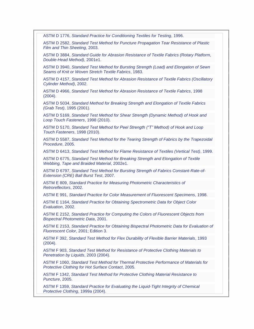
ASTM D 1776, Standard Practice for Conditioning Textiles for Testing, 1996.
ASTM D 2582, Standard Test Method for Puncture Propagation Tear Resistance of Plastic Film and Thin Sheeting, 2003.
ASTM D 3884, Standard Guide for Abrasion Resistance of Textile Fabrics (Rotary Platform, Double-Head Method), 2001e1.
ASTM D 3940, Standard Test Method for Bursting Strength (Load) and Elongation of Sewn Seams of Knit or Woven Stretch Textile Fabrics, 1983.
ASTM D 4157, Standard Test Method for Abrasion Resistance of Textile Fabrics (Oscillatory Cylinder Method), 2002.
ASTM D 4966, Standard Test Method for Abrasion Resistance of Textile Fabrics, 1998 (2004).
ASTM D 5034, Standard Method for Breaking Strength and Elongation of Textile Fabrics (Grab Test), 1995 (2001).
ASTM D 5169, Standard Test Method for Shear Strength (Dynamic Method) of Hook and Loop Touch Fasteners, 1998 (2010).
ASTM D 5170, Standard Test Method for Peel Strength (“T” Method) of Hook and Loop Touch Fasteners, 1998 (2010).
ASTM D 5587, Standard Test Method for the Tearing Strength of Fabrics by the Trapezoidal Procedure, 2005.
ASTM D 6413, Standard Test Method for Flame Resistance of Textiles (Vertical Test), 1999.
ASTM D 6775, Standard Test Method for Breaking Strength and Elongation of Textile Webbing, Tape and Braided Material, 2002e1.
ASTM D 6797, Standard Test Method for Bursting Strength of Fabrics Constant-Rate-of-Extension (CRE) Ball Burst Test, 2007.
ASTM E 809, Standard Practice for Measuring Photometric Characteristics of Retroreflectors, 2002.
ASTM E 991, Standard Practice for Color Measurement of Fluorescent Specimens, 1998.
ASTM E 1164, Standard Practice for Obtaining Spectrometric Data for Object Color Evaluation, 2002.
ASTM E 2152, Standard Practice for Computing the Colors of Fluorescent Objects from Bispectral Photometric Data, 2001.
ASTM E 2153, Standard Practice for Obtaining Bispectral Photometric Data for Evaluation of Fluorescent Color, 2001; Edition 3.
ASTM F 392, Standard Test Method for Flex Durability of Flexible Barrier Materials, 1993 (2004).
ASTM F 903, Standard Test Method for Resistance of Protective Clothing Materials to Penetration by Liquids, 2003 (2004).
ASTM F 1060, Standard Test Method for Thermal Protective Performance of Materials for Protective Clothing for Hot Surface Contact, 2005.
ASTM F 1342, Standard Test Method for Protective Clothing Material Resistance to Puncture, 2005.
ASTM F 1359, Standard Practice for Evaluating the Liquid-Tight Integrity of Chemical Protective Clothing, 1999a (2004).
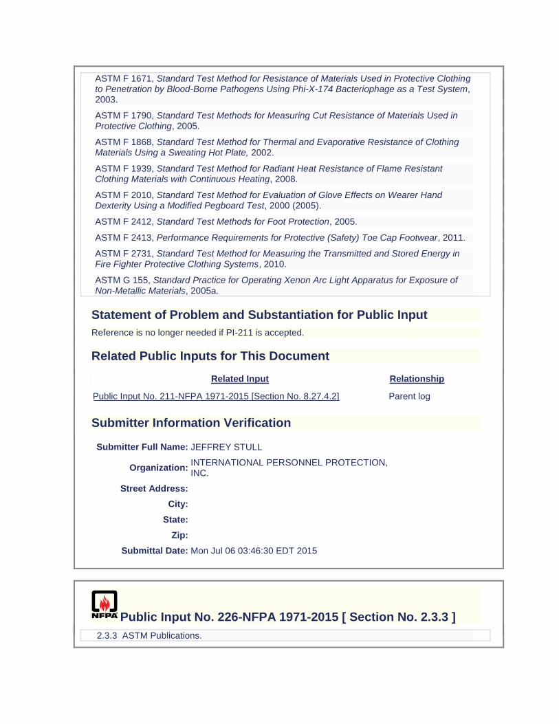
ASTM F 1671, Standard Test Method for Resistance of Materials Used in Protective Clothing to Penetration by Blood-Borne Pathogens Using Phi-X-174 Bacteriophage as a Test System, 2003.
ASTM F 1790, Standard Test Methods for Measuring Cut Resistance of Materials Used in Protective Clothing, 2005.
ASTM F 1868, Standard Test Method for Thermal and Evaporative Resistance of Clothing Materials Using a Sweating Hot Plate, 2002.
ASTM F 1939, Standard Test Method for Radiant Heat Resistance of Flame Resistant Clothing Materials with Continuous Heating, 2008.
ASTM F 2010, Standard Test Method for Evaluation of Glove Effects on Wearer Hand Dexterity Using a Modified Pegboard Test, 2000 (2005).
ASTM F 2412, Standard Test Methods for Foot Protection, 2005.
ASTM F 2413, Performance Requirements for Protective (Safety) Toe Cap Footwear, 2011.
ASTM F 2731, Standard Test Method for Measuring the Transmitted and Stored Energy in Fire Fighter Protective Clothing Systems, 2010.
ASTM G 155, Standard Practice for Operating Xenon Arc Light Apparatus for Exposure of Non-Metallic Materials, 2005a.
Statement of Problem and Substantiation for Public Input
Reference is no longer needed if PI-211 is accepted.
Related Public Inputs for This Document
Related Input Relationship
Public Input No. 211-NFPA 1971-2015 [Section No. 8.27.4.2] Parent log
Submitter Information Verification
Submitter Full Name: JEFFREY STULL
Organization: INTERNATIONAL PERSONNEL PROTECTION, INC.
Street Address:
City:
State:
Zip:
Submittal Date: Mon Jul 06 03:46:30 EDT 2015
Public Input No. 226-NFPA 1971-2015 [ Section No. 2.3.3 ]
2.3.3 ASTM Publications.
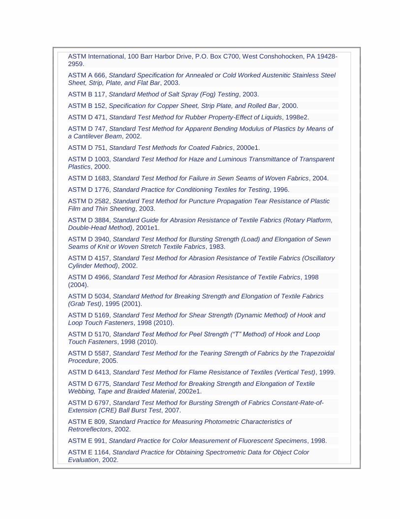
ASTM International, 100 Barr Harbor Drive, P.O. Box C700, West Conshohocken, PA 19428-2959.
ASTM A 666, Standard Specification for Annealed or Cold Worked Austenitic Stainless Steel Sheet, Strip, Plate, and Flat Bar, 2003.
ASTM B 117, Standard Method of Salt Spray (Fog) Testing, 2003.
ASTM B 152, Specification for Copper Sheet, Strip Plate, and Rolled Bar, 2000.
ASTM D 471, Standard Test Method for Rubber Property-Effect of Liquids, 1998e2.
ASTM D 747, Standard Test Method for Apparent Bending Modulus of Plastics by Means of a Cantilever Beam, 2002.
ASTM D 751, Standard Test Methods for Coated Fabrics, 2000e1.
ASTM D 1003, Standard Test Method for Haze and Luminous Transmittance of Transparent Plastics, 2000.
ASTM D 1683, Standard Test Method for Failure in Sewn Seams of Woven Fabrics, 2004.
ASTM D 1776, Standard Practice for Conditioning Textiles for Testing, 1996.
ASTM D 2582, Standard Test Method for Puncture Propagation Tear Resistance of Plastic Film and Thin Sheeting, 2003.
ASTM D 3884, Standard Guide for Abrasion Resistance of Textile Fabrics (Rotary Platform, Double-Head Method), 2001e1.
ASTM D 3940, Standard Test Method for Bursting Strength (Load) and Elongation of Sewn Seams of Knit or Woven Stretch Textile Fabrics, 1983.
ASTM D 4157, Standard Test Method for Abrasion Resistance of Textile Fabrics (Oscillatory Cylinder Method), 2002.
ASTM D 4966, Standard Test Method for Abrasion Resistance of Textile Fabrics, 1998 (2004).
ASTM D 5034, Standard Method for Breaking Strength and Elongation of Textile Fabrics (Grab Test), 1995 (2001).
ASTM D 5169, Standard Test Method for Shear Strength (Dynamic Method) of Hook and Loop Touch Fasteners, 1998 (2010).
ASTM D 5170, Standard Test Method for Peel Strength (“T” Method) of Hook and Loop Touch Fasteners, 1998 (2010).
ASTM D 5587, Standard Test Method for the Tearing Strength of Fabrics by the Trapezoidal Procedure, 2005.
ASTM D 6413, Standard Test Method for Flame Resistance of Textiles (Vertical Test), 1999.
ASTM D 6775, Standard Test Method for Breaking Strength and Elongation of Textile Webbing, Tape and Braided Material, 2002e1.
ASTM D 6797, Standard Test Method for Bursting Strength of Fabrics Constant-Rate-of-Extension (CRE) Ball Burst Test, 2007.
ASTM E 809, Standard Practice for Measuring Photometric Characteristics of Retroreflectors, 2002.
ASTM E 991, Standard Practice for Color Measurement of Fluorescent Specimens, 1998.
ASTM E 1164, Standard Practice for Obtaining Spectrometric Data for Object Color Evaluation, 2002.

ASTM E 2152, Standard Practice for Computing the Colors of Fluorescent Objects from Bispectral Photometric Data, 2001.
ASTM E 2153, Standard Practice for Obtaining Bispectral Photometric Data for Evaluation of Fluorescent Color, 2001; Edition 3.
ASTM F 392, Standard Test Method for Flex Durability of Flexible Barrier Materials, 1993 (2004).
ASTM F 903, Standard Test Method for Resistance of Protective Clothing Materials to Penetration by Liquids, 2003 (2004).
ASTM F 1060, Standard Test Method for Thermal Protective Performance of Materials for Protective Clothing for Hot Surface Contact, 2005.
ASTM F 1342, Standard Test Method for Protective Clothing Material Resistance to Puncture, 2005.
ASTM F 1359, Standard Practice for Evaluating the Liquid-Tight Integrity of Chemical Protective Clothing, 1999a (2004).
ASTM F 1671, Standard Test Method for Resistance of Materials Used in Protective Clothing to Penetration by Blood-Borne Pathogens Using Phi-X-174 Bacteriophage as a Test System, 2003.
ASTM F 1790, Standard Test Methods for Measuring Cut Resistance of Materials Used in Protective Clothing, 2005.
ASTM F 1868, Standard Test Method for Thermal and Evaporative Resistance of Clothing Materials Using a Sweating Hot Plate, 2002.
ASTM F 1939, Standard Test Method for Radiant Heat Resistance of Flame Resistant Clothing Materials with Continuous Heating, 2008.
ASTM F 2010, Standard Test Method for Evaluation of Glove Effects on Wearer Hand Dexterity Using a Modified Pegboard Test, 2000 (2005).
ASTM F 2412, Standard Test Methods for Foot Protection, 200520XX.
ASTM F 2413, Performance Requirements for Protective (Safety) Toe Cap Footwear, 201120XX.
ASTM F 2731, Standard Test Method for Measuring the Transmitted and Stored Energy in Fire Fighter Protective Clothing Systems, 2010.
ASTM G 155, Standard Practice for Operating Xenon Arc Light Apparatus for Exposure of Non-Metallic Materials, 2005a.
Statement of Problem and Substantiation for Public Input
Both ASTM 2412 and 2413 are in the process of being revised. No major changes are being proposed for these standards. If one or both are published before the comment period ends for NFPA 1971, then proposing to update to latest editions.
Submitter Information Verification
Submitter Full Name: ROBIN TUTOR
Organization: UL LLC
Street Address:
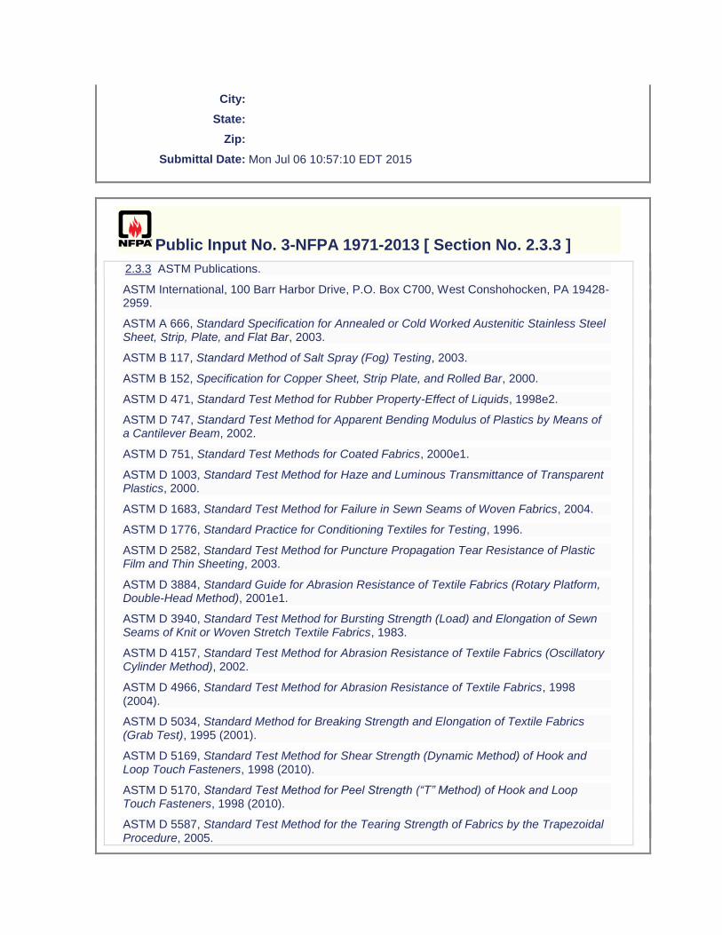
City:
State:
Zip:
Submittal Date: Mon Jul 06 10:57:10 EDT 2015
Public Input No. 3-NFPA 1971-2013 [ Section No. 2.3.3 ]
2.3.3 ASTM Publications.
ASTM International, 100 Barr Harbor Drive, P.O. Box C700, West Conshohocken, PA 19428-2959.
ASTM A 666, Standard Specification for Annealed or Cold Worked Austenitic Stainless Steel Sheet, Strip, Plate, and Flat Bar, 2003.
ASTM B 117, Standard Method of Salt Spray (Fog) Testing, 2003.
ASTM B 152, Specification for Copper Sheet, Strip Plate, and Rolled Bar, 2000.
ASTM D 471, Standard Test Method for Rubber Property-Effect of Liquids, 1998e2.
ASTM D 747, Standard Test Method for Apparent Bending Modulus of Plastics by Means of a Cantilever Beam, 2002.
ASTM D 751, Standard Test Methods for Coated Fabrics, 2000e1.
ASTM D 1003, Standard Test Method for Haze and Luminous Transmittance of Transparent Plastics, 2000.
ASTM D 1683, Standard Test Method for Failure in Sewn Seams of Woven Fabrics, 2004.
ASTM D 1776, Standard Practice for Conditioning Textiles for Testing, 1996.
ASTM D 2582, Standard Test Method for Puncture Propagation Tear Resistance of Plastic Film and Thin Sheeting, 2003.
ASTM D 3884, Standard Guide for Abrasion Resistance of Textile Fabrics (Rotary Platform, Double-Head Method), 2001e1.
ASTM D 3940, Standard Test Method for Bursting Strength (Load) and Elongation of Sewn Seams of Knit or Woven Stretch Textile Fabrics, 1983.
ASTM D 4157, Standard Test Method for Abrasion Resistance of Textile Fabrics (Oscillatory Cylinder Method), 2002.
ASTM D 4966, Standard Test Method for Abrasion Resistance of Textile Fabrics, 1998 (2004).
ASTM D 5034, Standard Method for Breaking Strength and Elongation of Textile Fabrics (Grab Test), 1995 (2001).
ASTM D 5169, Standard Test Method for Shear Strength (Dynamic Method) of Hook and Loop Touch Fasteners, 1998 (2010).
ASTM D 5170, Standard Test Method for Peel Strength (“T” Method) of Hook and Loop Touch Fasteners, 1998 (2010).
ASTM D 5587, Standard Test Method for the Tearing Strength of Fabrics by the Trapezoidal Procedure, 2005.
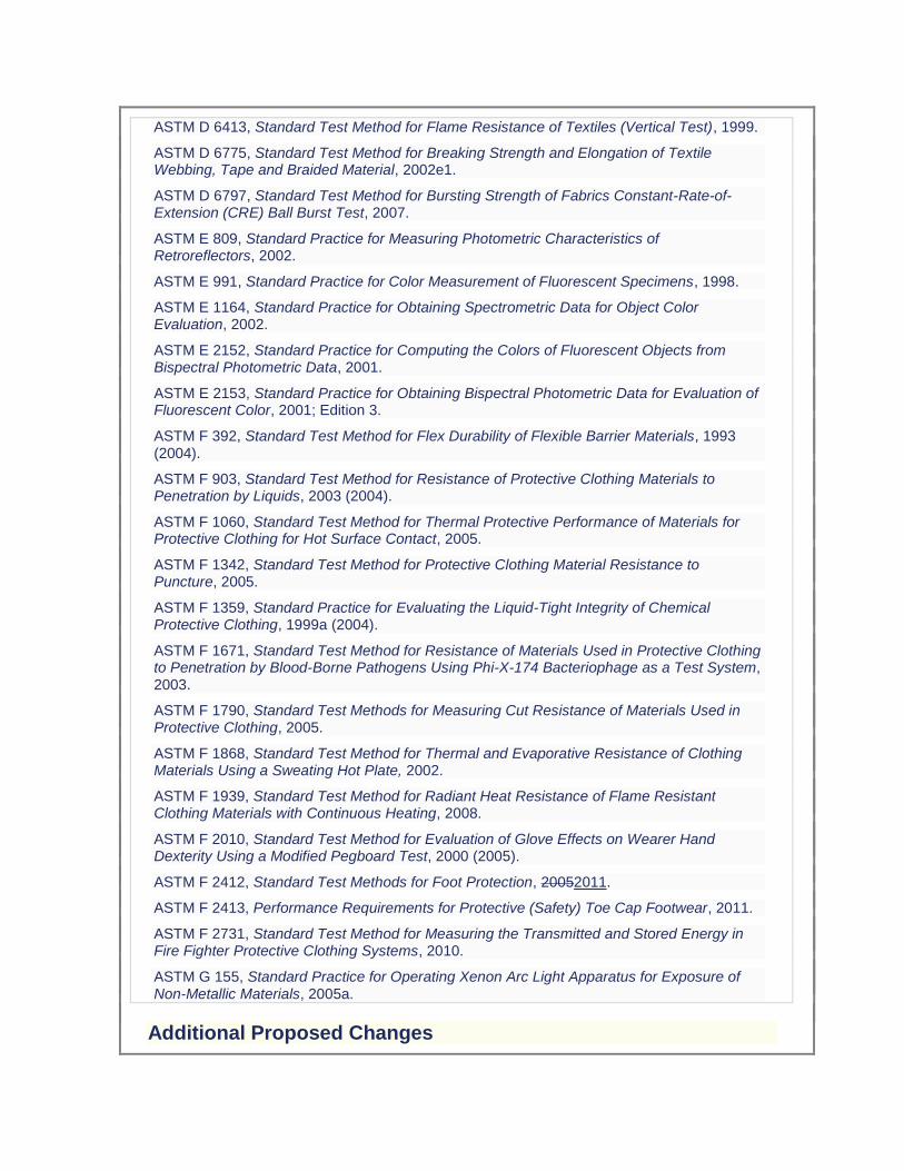
ASTM D 6413, Standard Test Method for Flame Resistance of Textiles (Vertical Test), 1999.
ASTM D 6775, Standard Test Method for Breaking Strength and Elongation of Textile Webbing, Tape and Braided Material, 2002e1.
ASTM D 6797, Standard Test Method for Bursting Strength of Fabrics Constant-Rate-of-Extension (CRE) Ball Burst Test, 2007.
ASTM E 809, Standard Practice for Measuring Photometric Characteristics of Retroreflectors, 2002.
ASTM E 991, Standard Practice for Color Measurement of Fluorescent Specimens, 1998.
ASTM E 1164, Standard Practice for Obtaining Spectrometric Data for Object Color Evaluation, 2002.
ASTM E 2152, Standard Practice for Computing the Colors of Fluorescent Objects from Bispectral Photometric Data, 2001.
ASTM E 2153, Standard Practice for Obtaining Bispectral Photometric Data for Evaluation of Fluorescent Color, 2001; Edition 3.
ASTM F 392, Standard Test Method for Flex Durability of Flexible Barrier Materials, 1993 (2004).
ASTM F 903, Standard Test Method for Resistance of Protective Clothing Materials to Penetration by Liquids, 2003 (2004).
ASTM F 1060, Standard Test Method for Thermal Protective Performance of Materials for Protective Clothing for Hot Surface Contact, 2005.
ASTM F 1342, Standard Test Method for Protective Clothing Material Resistance to Puncture, 2005.
ASTM F 1359, Standard Practice for Evaluating the Liquid-Tight Integrity of Chemical Protective Clothing, 1999a (2004).
ASTM F 1671, Standard Test Method for Resistance of Materials Used in Protective Clothing to Penetration by Blood-Borne Pathogens Using Phi-X-174 Bacteriophage as a Test System, 2003.
ASTM F 1790, Standard Test Methods for Measuring Cut Resistance of Materials Used in Protective Clothing, 2005.
ASTM F 1868, Standard Test Method for Thermal and Evaporative Resistance of Clothing Materials Using a Sweating Hot Plate, 2002.
ASTM F 1939, Standard Test Method for Radiant Heat Resistance of Flame Resistant Clothing Materials with Continuous Heating, 2008.
ASTM F 2010, Standard Test Method for Evaluation of Glove Effects on Wearer Hand Dexterity Using a Modified Pegboard Test, 2000 (2005).
ASTM F 2412, Standard Test Methods for Foot Protection, 20052011.
ASTM F 2413, Performance Requirements for Protective (Safety) Toe Cap Footwear, 2011.
ASTM F 2731, Standard Test Method for Measuring the Transmitted and Stored Energy in Fire Fighter Protective Clothing Systems, 2010.
ASTM G 155, Standard Practice for Operating Xenon Arc Light Apparatus for Exposure of Non-Metallic Materials, 2005a.
Additional Proposed Changes

File Name Description Approved
Proposed_TIA_1092_1971_.docx Balloted TIA
Statement of Problem and Substantiation for Public Input
Note: This Public Input originates from Tentative Interim Amendment 1971-13-2 (TIA 1092) issued by the Standards Council on March 7, 2013. 1. The ASTM 2412 Standard needs to be updated to the current edition. 2, 3, and 14. The specific requirements for glove labels, which included type of fiber or material type, were inadvertently included in the generic list of requirements for labels on all ensemble elements. Since the majority of fabrics and materials used in construction of many of the ensemble elements contain multiple fibers and numerous blends, even attempting to include this level of detail on every product label would cause mass confusion. The issue becomes even more exacerbated by the minimum font sizes required on label text and by a garment specific label requirement, also included in the generic list, which mandates explicit component names as per the certification listing. This change provides the generic requirements for all labels, and then separates the specific ensemble element label requirements into subsets to avoid any interpretation issues. 4. The NFPA 1971 proposal (1971-46, Log CP-50) neglected to include the test method reference to Section 8.4 as well as the requirement for char length. NFPA 1971, 2013 edition references several flame resistance tests. It is important the standard references the correct flame resistance test and section number to insure the correct testing procedures are being followed. It was also the technical committee’s intent, based on historical data, to have the glove interface component evaluated for char length in addition to afterflame. 5. The NFPA 1971 proposal (1971-46, Log CP-50) neglected to include the test method reference to Section 8.4 as well as the requirement for char length. NFPA 1971, 2013 edition references several flame resistance tests. It is important the standard references the correct flame resistance test and section number to insure the correct testing procedures are being followed. It was also the technical committee’s intent, based on historical data, to have the glove extension component evaluated for char length in addition to afterflame. 6. This change brings this requirement in line with EN ISO 20345:2011. 7. The current laundering method described in Section 8.1.11 only accounts for water levels when laundering garments and CBRN Materials. The 2013 edition of NFPA 1971 now requires gloves and glove pouches to be laundered using Section 8.1.11 as a precondition. However a table for gloves and glove pouch water levels were not included. The water levels for the glove and glove pouch wash cycle needs to be specified in NFPA 1971, 2013 edition in order to allow for the front load wash machines to be properly programmed at the testing laboratories. The highest water levels currently in the standard were chosen to account for usage of both 35 lb and 50 lb capacity front-loading machines. The higher levels will also accommodate a full load of gloves/glove pouches and eliminate any risk associated with residual detergent. 8, 9, 15 and 16. Some changes made to the way the measurement of hood shrinkage were specified in cleaning shrinkage as part of the NFPA 1971-2013 revision would prevent any hood from being certified to the new requirements. There was also an inconsistency between how hood shrinkage was evaluated for both thermal and cleaning shrinkage for the interpretation of test results that would lead to inconsistent determinations of compliance among testing laboratories. The proposed changes using the same approach established in the 2007 edition of NFPA 1971 for applying cleaning shrinkage criteria while clarifications have been made for interpretation of permitted shrinkage in both cleaning and thermal shrinkage test methods. 10. NFPA 1971, 2013 edition has sections for glove pouch construction, sections 8.1.15 and 8.1.16. Section 8.27.8.2, section for Liquid Penetration Resistance, should reference section 8.1.16 for moisture barrier testing. 11. NFPA 1971, 2013 edition has sections for glove pouch construction, sections 8.1.15 and 8.1.16. Section 8.28.8.2, section for Viral Penetration Resistance, should reference section 8.1.16 for moisture barrier testing. 12. The ISO 13287 standard does not provide criteria for the evaluation of systematic increase or decrease of values. Also, the current calibration language is not clear. 13. The test apparatus will be maxed out if the test subject uses their arm’s range of motion to perform this test. In order to achieve more accurate results it is important the test subject use their wrist’s range of motion to perform
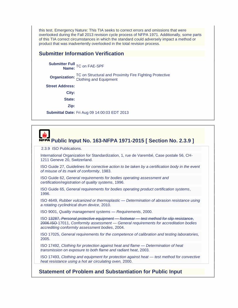
this test. Emergency Nature: This TIA seeks to correct errors and omissions that were overlooked during the Fall 2013 revision cycle process of NFPA 1971. Additionally, some parts of this TIA correct circumstances in which the standard could adversely impact a method or product that was inadvertently overlooked in the total revision process.
Submitter Information Verification
Submitter Full Name:
TC on FAE-SPF
Organization: TC on Structural and Proximity Fire Fighting Protective Clothing and Equipment
Street Address:
City:
State:
Zip:
Submittal Date: Fri Aug 09 14:00:03 EDT 2013
Public Input No. 163-NFPA 1971-2015 [ Section No. 2.3.9 ]
2.3.9 ISO Publications.
International Organization for Standardization, 1, rue de Varembé, Case postale 56, CH-1211 Geneve 20, Switzerland.
ISO Guide 27, Guidelines for corrective action to be taken by a certification body in the event of misuse of its mark of conformity, 1983.
ISO Guide 62, General requirements for bodies operating assessment and certification/registration of quality systems, 1996.
ISO Guide 65, General requirements for bodies operating product certification systems, 1996.
ISO 4649, Rubber vulcanized or thermoplastic — Determination of abrasion resistance using a rotating cyclindrical drum device, 2010.
ISO 9001, Quality management systems — Requirements, 2000.
ISO 13287, Personal protective equipment — footwear — test method for slip resistance, 2006.ISO 17011, Conformity assessment — General requirements for accreditation bodies accrediting conformity assessment bodies, 2004.
ISO 17025, General requirements for the competence of calibration and testing laboratories, 2005.
ISO 17492, Clothing for protection against heat and flame — Determination of heat transmission on exposure to both flame and radiant heat, 2003.
ISO 17493, Clothing and equipment for protection against heat — test method for convective heat resistance using a hot air circulating oven, 2000.
Statement of Problem and Substantiation for Public Input
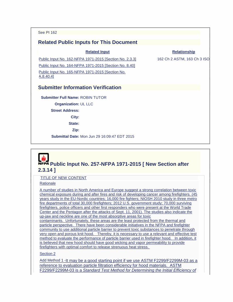
See PI 162
Related Public Inputs for This Document
Related Input Relationship
Public Input No. 162-NFPA 1971-2015 [Section No. 2.3.3] 162 Ch 2 ASTM, 163 Ch 3 ISO
Public Input No. 164-NFPA 1971-2015 [Section No. 8.40]
Public Input No. 165-NFPA 1971-2015 [Section No. A.8.40.4]
Submitter Information Verification
Submitter Full Name: ROBIN TUTOR
Organization: UL LLC
Street Address:
City:
State:
Zip:
Submittal Date: Mon Jun 29 16:09:47 EDT 2015
Public Input No. 257-NFPA 1971-2015 [ New Section after 2.3.14 ]
TITLE OF NEW CONTENT
Rationale
A number of studies in North America and Europe suggest a strong correlation between toxic chemical exposure during and after fires and risk of developing cancer among firefighters. (45 years study in the EU-Nordic countries; 16,000 fire fighters; NIOSH 2010 study in three metro fire departments of total 30,000 firefighters; 2012 U.S. government study; 70,000 surviving firefighters, police officers and other first responders who were present at the World Trade Center and the Pentagon after the attacks of Sept. 11, 2001). The studies also indicate the up-jaw and neckline are one of the most absorptive areas for toxic contaminants. Unfortunately, these areas are the least protected from the thermal and particle perspective. There have been considerable initiatives in the NFPA and firefighter community to use additional particle barrier to prevent toxic substances to penetrate through very open and porous knit hood. Thereby, it is necessary to use a relevant and effective test method to evaluate the performance of particle barrier used in firefighter hood. In addition, it is believed that new hood should have good wicking and vapor permeability to provide firefighters with optimal comfort to release strenuous heat stress.
Section 2
Add Method 1 -It may be a good starting point if we use ASTM F2299/F2299M-03 as a reference to evaluation particle filtration efficiency for hood materials. ASTM F2299/F2299M-03 is a Standard Test Method for Determining the Initial Efficiency of
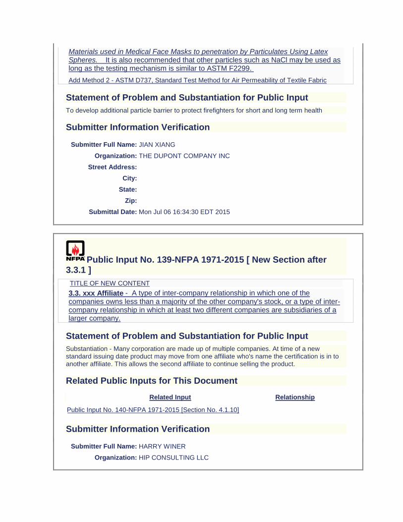
Materials used in Medical Face Masks to penetration by Particulates Using Latex Spheres. It is also recommended that other particles such as NaCl may be used as long as the testing mechanism is similar to ASTM F2299.
Add Method 2 - ASTM D737, Standard Test Method for Air Permeability of Textile Fabric
Statement of Problem and Substantiation for Public Input
To develop additional particle barrier to protect firefighters for short and long term health
Submitter Information Verification
Submitter Full Name: JIAN XIANG
Organization: THE DUPONT COMPANY INC
Street Address:
City:
State:
Zip:
Submittal Date: Mon Jul 06 16:34:30 EDT 2015
Public Input No. 139-NFPA 1971-2015 [ New Section after 3.3.1 ]
TITLE OF NEW CONTENT
3.3. xxx Affiliate - A type of inter-company relationship in which one of the
companies owns less than a majority of the other company's stock, or a type of inter-company relationship in which at least two different companies are subsidiaries of a larger company.
Statement of Problem and Substantiation for Public Input
Substantiation - Many corporation are made up of multiple companies. At time of a new standard issuing date product may move from one affiliate who's name the certification is in to another affiliate. This allows the second affiliate to continue selling the product.
Related Public Inputs for This Document
Related Input Relationship
Public Input No. 140-NFPA 1971-2015 [Section No. 4.1.10]
Submitter Information Verification
Submitter Full Name: HARRY WINER
Organization: HIP CONSULTING LLC
Street Address:
City:
State:
Zip:
Submittal Date: Mon Jun 29 08:30:26 EDT 2015
Public Input No. 179-NFPA 1971-2015 [ New Section after 3.3.76 ]
3.3.X Manufacturing Facility. A facility that is involved in the production or assembly or
final inspection or labeling of the compliant end product.
Statement of Problem and Substantiation for Public Input
See PI 178
Related Public Inputs for This Document
Related Input Relationship
Public Input No. 178-NFPA 1971-2015 [Section No. 3.3.76]
Public Input No. 180-NFPA 1971-2015 [Section No. 3.3.116]
Public Input No. 181-NFPA 1971-2015 [Section No. 4.2.9]
Public Input No. 182-NFPA 1971-2015 [Sections 4.5.3, 4.5.4]
Public Input No. 183-NFPA 1971-2015 [Section No. A.4.5.4]
Submitter Information Verification
Submitter Full Name: ROBIN TUTOR
Organization: UL LLC
Street Address:
City:
State:
Zip:
Submittal Date: Wed Jul 01 16:44:46 EDT 2015
Public Input No. 178-NFPA 1971-2015 [ Section No. 3.3.76 ]
3.3.76 Manufacturer.
The entity that directs and controls any of the following: compliant product design, compliant product manufacturing, or compliant product quality assurance; or the entity that assumes the liability for the compliant product or provides the warranty for the compliant product.
Statement of Problem and Substantiation for Public Input
The use of the term manufacturer is inconsistent throughout the document. In previous revisions of the standard, the definition for manufacturer was expanded to include all entities that require ISO 9001 registration. However, this expanded definition was not appropriate for the remaining uses of the term manufacturer within the document. Therefore, a more succinct definition for manufacturer is proposed while 4.5.3 will be expanded to clarify which entities are required to have ISO 9001. Also the current term manufacturer is used to describe the warrantee/liability function as well as the actual assembly function. This can lead to confusion and misinterpretation of the requirements in chapter 4. Therefore a new definition of manufacturing facility will be added to distinguish between the terms manufacturer and manufacturing facility and to distinguish between these two functions.
Related Public Inputs for This Document
Related Input Relationship
Public Input No. 179-NFPA 1971-2015 [New Section after 3.3.76]
Public Input No. 180-NFPA 1971-2015 [Section No. 3.3.116]
Public Input No. 181-NFPA 1971-2015 [Section No. 4.2.9]
Public Input No. 182-NFPA 1971-2015 [Sections 4.5.3, 4.5.4]
Public Input No. 183-NFPA 1971-2015 [Section No. A.4.5.4]
Submitter Information Verification
Submitter Full Name: ROBIN TUTOR
Organization: UL LLC
Street Address:
City:
State:
Zip:
Submittal Date: Wed Jul 01 16:41:18 EDT 2015
Public Input No. 180-NFPA 1971-2015 [ Section No. 3.3.116 ]
3.3.116 Sample.
(1) The ensemble, element, component, or composite that is conditioned for testing. (2) Ensembles, elements, items, or components that are randomly selected from the manufacturermanufacturing facility's production line, from the manufacturer's or manufacturing facility's inventory, or from the open market.
Statement of Problem and Substantiation for Public Input
See PI 178
Related Public Inputs for This Document
Related Input Relationship
Public Input No. 178-NFPA 1971-2015 [Section No. 3.3.76]
Public Input No. 179-NFPA 1971-2015 [New Section after 3.3.76]
Public Input No. 181-NFPA 1971-2015 [Section No. 4.2.9]
Public Input No. 182-NFPA 1971-2015 [Sections 4.5.3, 4.5.4]
Public Input No. 183-NFPA 1971-2015 [Section No. A.4.5.4]
Submitter Information Verification
Submitter Full Name: ROBIN TUTOR
Organization: UL LLC
Street Address:
City:
State:
Zip:
Submittal Date: Wed Jul 01 16:47:03 EDT 2015
Public Input No. 52-NFPA 1971-2014 [ New Section after 3.3.117 ]
TITLE OF NEW CONTENT
Seam Failure- Point at which an external Force ruptures a sewing thread or causes fabric failure within 6mm of the nearest seam thread
Statement of Problem and Substantiation for Public Input
Further clarifiication is needed for fabric failure versus seam failure within Section 7.1.13.2. Oftentimes it is subjective whether the stitching is the source of fabric failures.
Submitter Information Verification
Submitter Full Name: Jason Allen
Organization: Intertek Testing Services
Street Address:
City:
State:
Zip:
Submittal Date: Tue Jul 01 16:05:20 EDT 2014
Public Input No. 140-NFPA 1971-2015 [ Section No. 4.1.10 ]
4.1.10
The certification organization shall require manufacturers and affiliates to remove all certification labels and product labels indicating compliance with the 2007 2013 edition of NFPA 1971, Standard on Protective Ensembles for Structural Fire Fighting and Proximity Fire Fighting, from all products that are under the control of the manufacturer and affiliates on
August 29, 2013, and the certification organization shall verify this action is taken.
Statement of Problem and Substantiation for Public Input
Substantiation - Many corporation are made up of multiple companies. At time of a new standard issuing date product may move from one affiliate who's name the certification is in to another affiliate. This allows the second affiliate to continue selling the product.
Related Public Inputs for This Document
Related Input Relationship
Public Input No. 139-NFPA 1971-2015 [New Section after 3.3.1]
Submitter Information Verification
Submitter Full Name: HARRY WINER
Organization: HIP CONSULTING LLC
Street Address:
City:
State:
Zip:
Submittal Date: Mon Jun 29 08:37:50 EDT 2015
Public Input No. 181-NFPA 1971-2015 [ Section No. 4.2.9 ]
4.2.9*
The certification organization shall have a follow-up inspection program of the manufacturer's manufacturing facilities of the compliant product with at least two random and unannounced visits per 12-month period to verify the product's continued
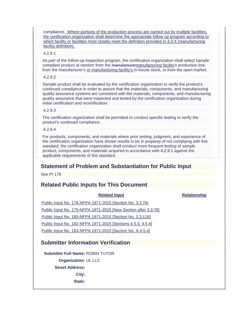
compliance. Where portions of the production process are carried out by multiple facilities, the certification organization shall determine the appropriate follow up program according to which facility or facilities most closely meet the definition provided in 3.3.X (manufacturing facility definition).
4.2.9.1
As part of the follow-up inspection program, the certification organization shall select sample compliant product at random from the manufacturermanufacturing facility's production line, from the manufacturer's or manufacturing facility's in-house stock, or from the open market.
4.2.9.2
Sample product shall be evaluated by the certification organization to verify the product's continued compliance in order to assure that the materials, components, and manufacturing quality assurance systems are consistent with the materials, components, and manufacturing quality assurance that were inspected and tested by the certification organization during initial certification and recertification.
4.2.9.3
The certification organization shall be permitted to conduct specific testing to verify the product's continued compliance.
4.2.9.4
For products, components, and materials where prior testing, judgment, and experience of the certification organization have shown results to be in jeopardy of not complying with this standard, the certification organization shall conduct more frequent testing of sample product, components, and materials acquired in accordance with 4.2.9.1 against the applicable requirements of this standard.
Statement of Problem and Substantiation for Public Input
See PI 178
Related Public Inputs for This Document
Related Input Relationship
Public Input No. 178-NFPA 1971-2015 [Section No. 3.3.76]
Public Input No. 179-NFPA 1971-2015 [New Section after 3.3.76]
Public Input No. 180-NFPA 1971-2015 [Section No. 3.3.116]
Public Input No. 182-NFPA 1971-2015 [Sections 4.5.3, 4.5.4]
Public Input No. 183-NFPA 1971-2015 [Section No. A.4.5.4]
Submitter Information Verification
Submitter Full Name: ROBIN TUTOR
Organization: UL LLC
Street Address:
City:
State:
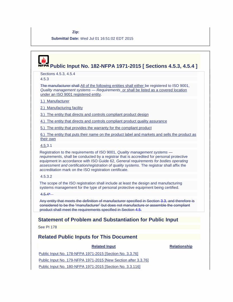
Zip:
Submittal Date: Wed Jul 01 16:51:02 EDT 2015
Public Input No. 182-NFPA 1971-2015 [ Sections 4.5.3, 4.5.4 ]
Sections 4.5.3, 4.5.4
4.5.3
The manufacturer shall All of the following entities shall either be registered to ISO 9001, Quality management systems — Requirements or shall be listed as a covered location under an ISO 9001 registered entity.
1.) Manufacturer
2.) Manufacturing facility
3.) The entity that directs and controls compliant product design
4.) The entity that directs and controls compliant product quality assurance
5.) The entity that provides the warranty for the compliant product
6.) The entity that puts their name on the product label and markets and sells the product as their own
4.5.3.1
Registration to the requirements of ISO 9001, Quality management systems — requirements, shall be conducted by a registrar that is accredited for personal protective equipment in accordance with ISO Guide 62, General requirements for bodies operating assessment and certification/registration of quality systems. The registrar shall affix the accreditation mark on the ISO registration certificate.
4.5.3.2
The scope of the ISO registration shall include at least the design and manufacturing systems management for the type of personal protective equipment being certified.
4.5.4*
Any entity that meets the definition of manufacturer specified in Section 3.3, and therefore is considered to be the “manufacturer” but does not manufacture or assemble the compliant product shall meet the requirements specified in Section 4.5.
Statement of Problem and Substantiation for Public Input
See PI 178
Related Public Inputs for This Document
Related Input Relationship
Public Input No. 178-NFPA 1971-2015 [Section No. 3.3.76]
Public Input No. 179-NFPA 1971-2015 [New Section after 3.3.76]
Public Input No. 180-NFPA 1971-2015 [Section No. 3.3.116]
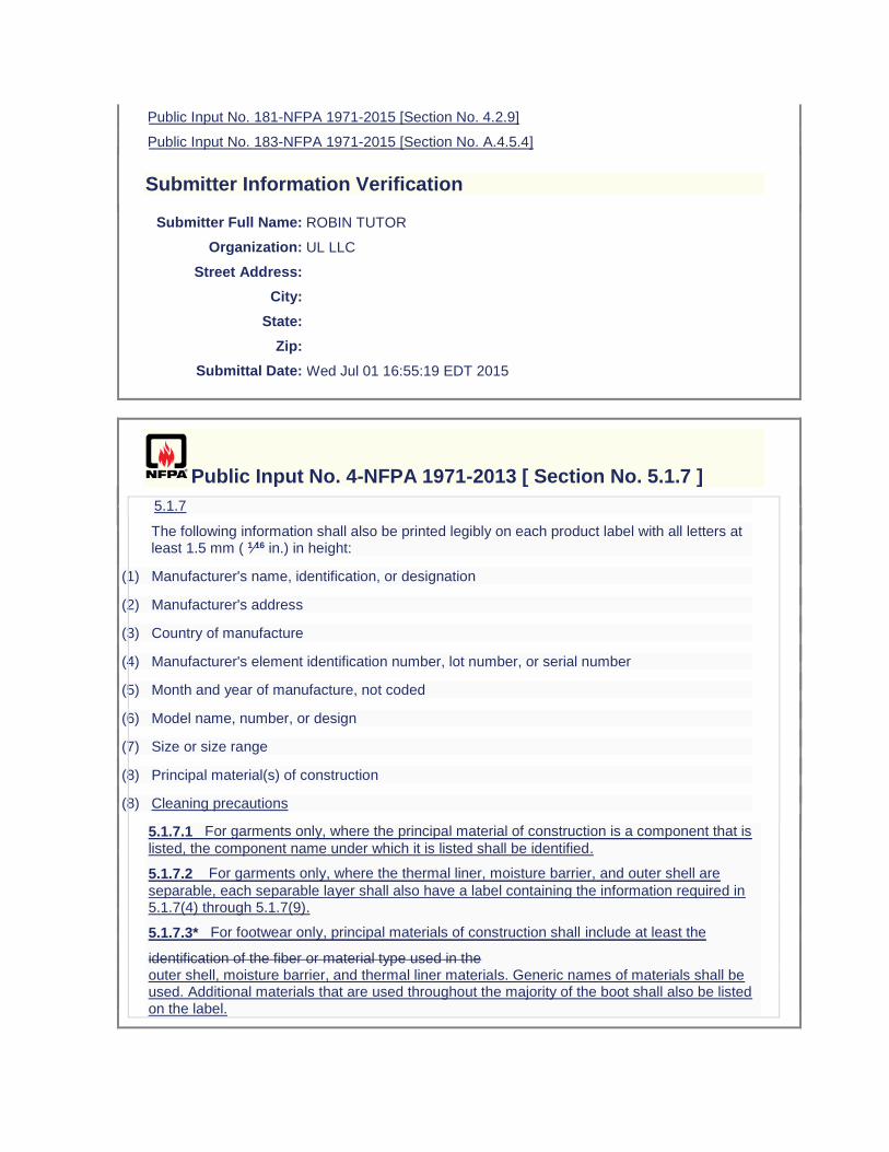
Public Input No. 181-NFPA 1971-2015 [Section No. 4.2.9]
Public Input No. 183-NFPA 1971-2015 [Section No. A.4.5.4]
Submitter Information Verification
Submitter Full Name: ROBIN TUTOR
Organization: UL LLC
Street Address:
City:
State:
Zip:
Submittal Date: Wed Jul 01 16:55:19 EDT 2015
Public Input No. 4-NFPA 1971-2013 [ Section No. 5.1.7 ]
5.1.7
The following information shall also be printed legibly on each product label with all letters at least 1.5 mm ( 1⁄16 in.) in height:
(1) Manufacturer's name, identification, or designation
(2) Manufacturer's address
(3) Country of manufacture
(4) Manufacturer's element identification number, lot number, or serial number
(5) Month and year of manufacture, not coded
(6) Model name, number, or design
(7) Size or size range
(8) Principal material(s) of construction
(8) Cleaning precautions
5.1.7.1 For garments only, where the principal material of construction is a component that is
listed, the component name under which it is listed shall be identified.
5.1.7.2 For garments only, where the thermal liner, moisture barrier, and outer shell are
separable, each separable layer shall also have a label containing the information required in 5.1.7(4) through 5.1.7(9).
5.1.7.3* For footwear only, principal materials of construction shall include at least the
identification of the fiber or material type used in the outer shell, moisture barrier, and thermal liner materials. Generic names of materials shall be used. Additional materials that are used throughout the majority of the boot shall also be listed on the label.
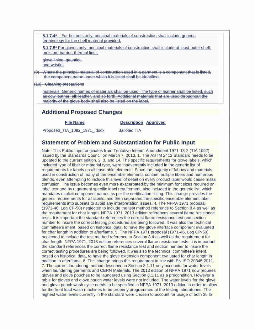
5.1.7.4* For helmets only, principal materials of construction shall include generic
terminology for the shell material provided.
5.1.7.5* For gloves only, principal materials of construction shall include at least outer shell,
moisture barrier, thermal liner,
glove lining, gauntlet, and wristlet
(9) Where the principal material of construction used in a garment is a component that is listed, the component name under which it is listed shall be identified.
(10) Cleaning precautions
materials. Generic names of materials shall be used. The type of leather shall be listed, such as cow leather, elk leather, and so forth. Additional materials that are used throughout the majority of the glove body shall also be listed on the label.
Additional Proposed Changes
File Name Description Approved
Proposed_TIA_1092_1971_.docx Balloted TIA
Statement of Problem and Substantiation for Public Input
Note: This Public Input originates from Tentative Interim Amendment 1971-13-2 (TIA 1092) issued by the Standards Council on March 7, 2013. 1. The ASTM 2412 Standard needs to be updated to the current edition. 2, 3, and 14. The specific requirements for glove labels, which included type of fiber or material type, were inadvertently included in the generic list of requirements for labels on all ensemble elements. Since the majority of fabrics and materials used in construction of many of the ensemble elements contain multiple fibers and numerous blends, even attempting to include this level of detail on every product label would cause mass confusion. The issue becomes even more exacerbated by the minimum font sizes required on label text and by a garment specific label requirement, also included in the generic list, which mandates explicit component names as per the certification listing. This change provides the generic requirements for all labels, and then separates the specific ensemble element label requirements into subsets to avoid any interpretation issues. 4. The NFPA 1971 proposal (1971-46, Log CP-50) neglected to include the test method reference to Section 8.4 as well as the requirement for char length. NFPA 1971, 2013 edition references several flame resistance tests. It is important the standard references the correct flame resistance test and section number to insure the correct testing procedures are being followed. It was also the technical committee’s intent, based on historical data, to have the glove interface component evaluated for char length in addition to afterflame. 5. The NFPA 1971 proposal (1971-46, Log CP-50) neglected to include the test method reference to Section 8.4 as well as the requirement for char length. NFPA 1971, 2013 edition references several flame resistance tests. It is important the standard references the correct flame resistance test and section number to insure the correct testing procedures are being followed. It was also the technical committee’s intent, based on historical data, to have the glove extension component evaluated for char length in addition to afterflame. 6. This change brings this requirement in line with EN ISO 20345:2011. 7. The current laundering method described in Section 8.1.11 only accounts for water levels when laundering garments and CBRN Materials. The 2013 edition of NFPA 1971 now requires gloves and glove pouches to be laundered using Section 8.1.11 as a precondition. However a table for gloves and glove pouch water levels were not included. The water levels for the glove and glove pouch wash cycle needs to be specified in NFPA 1971, 2013 edition in order to allow for the front load wash machines to be properly programmed at the testing laboratories. The highest water levels currently in the standard were chosen to account for usage of both 35 lb
and 50 lb capacity front-loading machines. The higher levels will also accommodate a full load of gloves/glove pouches and eliminate any risk associated with residual detergent. 8, 9, 15 and 16. Some changes made to the way the measurement of hood shrinkage were specified in cleaning shrinkage as part of the NFPA 1971-2013 revision would prevent any hood from being certified to the new requirements. There was also an inconsistency between how hood shrinkage was evaluated for both thermal and cleaning shrinkage for the interpretation of test results that would lead to inconsistent determinations of compliance among testing laboratories. The proposed changes using the same approach established in the 2007 edition of NFPA 1971 for applying cleaning shrinkage criteria while clarifications have been made for interpretation of permitted shrinkage in both cleaning and thermal shrinkage test methods. 10. NFPA 1971, 2013 edition has sections for glove pouch construction, sections 8.1.15 and 8.1.16. Section 8.27.8.2, section for Liquid Penetration Resistance, should reference section 8.1.16 for moisture barrier testing. 11. NFPA 1971, 2013 edition has sections for glove pouch construction, sections 8.1.15 and 8.1.16. Section 8.28.8.2, section for Viral Penetration Resistance, should reference section 8.1.16 for moisture barrier testing. 12. The ISO 13287 standard does not provide criteria for the evaluation of systematic increase or decrease of values. Also, the current calibration language is not clear. 13. The test apparatus will be maxed out if the test subject uses their arm’s range of motion to perform this test. In order to achieve more accurate results it is important the test subject use their wrist’s range of motion to perform this test. Emergency Nature: This TIA seeks to correct errors and omissions that were overlooked during the Fall 2013 revision cycle process of NFPA 1971. Additionally, some parts of this TIA correct circumstances in which the standard could adversely impact a method or product that was inadvertently overlooked in the total revision process.
Submitter Information Verification
Submitter Full Name:
TC on FAE-SPF
Organization: TC on Structural and Proximity Fire Fighting Protective Clothing and Equipment
Street Address:
City:
State:
Zip:
Submittal Date: Fri Aug 09 14:06:53 EDT 2013
Public Input No. 5-NFPA 1971-2013 [ Sections 5.1.8, 5.1.9, 5.1.10, 5.1.11 ]
Sections 5.1.8, 5.1.9, 5.1.10, 5.1.11
5.1.8
For garments only, where the thermal liner, moisture barrier, and outer shell are separable, each separable layer shall also have a label containing the information required in 5.1.7 (4) through 5.1.7 (9).
5.1.9*

For principal materials of construction of boots, at least the outer shell, moisture barrier, and thermal liner shall be listed. Generic names of materials shall be used. Additional materials that are used throughout the majority of the boot shall also be listed on the label.
5.1.10*
For principal materials of construction of helmets, generic terminology for the shell material shall be provided.
5.1.11*
For principal materials of construction of gloves, at least outer shell, moisture barrier, thermal liner, and wristlet shall be listed. Generic names of materials shall be used. The type of leather shall be listed, such as cow leather, elk leather, and so forth. Additional materials that are used throughout the majority of the glove body shall also be listed on the label.
Additional Proposed Changes
File Name Description Approved
Proposed_TIA_1092_1971_.docx Balloted TIA
Statement of Problem and Substantiation for Public Input
Note: This Public Input originates from Tentative Interim Amendment 1971-13-2 (TIA 1092) issued by the Standards Council on March 7, 2013. 1. The ASTM 2412 Standard needs to be updated to the current edition. 2, 3, and 14. The specific requirements for glove labels, which included type of fiber or material type, were inadvertently included in the generic list of requirements for labels on all ensemble elements. Since the majority of fabrics and materials used in construction of many of the ensemble elements contain multiple fibers and numerous blends, even attempting to include this level of detail on every product label would cause mass confusion. The issue becomes even more exacerbated by the minimum font sizes required on label text and by a garment specific label requirement, also included in the generic list, which mandates explicit component names as per the certification listing. This change provides the generic requirements for all labels, and then separates the specific ensemble element label requirements into subsets to avoid any interpretation issues. 4. The NFPA 1971 proposal (1971-46, Log CP-50) neglected to include the test method reference to Section 8.4 as well as the requirement for char length. NFPA 1971, 2013 edition references several flame resistance tests. It is important the standard references the correct flame resistance test and section number to insure the correct testing procedures are being followed. It was also the technical committee’s intent, based on historical data, to have the glove interface component evaluated for char length in addition to afterflame. 5. The NFPA 1971 proposal (1971-46, Log CP-50) neglected to include the test method reference to Section 8.4 as well as the requirement for char length. NFPA 1971, 2013 edition references several flame resistance tests. It is important the standard references the correct flame resistance test and section number to insure the correct testing procedures are being followed. It was also the technical committee’s intent, based on historical data, to have the glove extension component evaluated for char length in addition to afterflame. 6. This change brings this requirement in line with EN ISO 20345:2011. 7. The current laundering method described in Section 8.1.11 only accounts for water levels when laundering garments and CBRN Materials. The 2013 edition of NFPA 1971 now requires gloves and glove pouches to be laundered using Section 8.1.11 as a precondition. However a table for gloves and glove pouch water levels were not included. The water levels for the glove and glove pouch wash cycle needs to be specified in NFPA 1971, 2013 edition in order to allow for the front load wash machines to be properly programmed at the testing laboratories. The highest water levels currently in the standard were chosen to account for usage of both 35 lb and 50 lb capacity front-loading machines. The higher levels will also accommodate a full load of gloves/glove pouches and eliminate any risk associated with residual detergent. 8, 9, 15 and

16. Some changes made to the way the measurement of hood shrinkage were specified in cleaning shrinkage as part of the NFPA 1971-2013 revision would prevent any hood from being certified to the new requirements. There was also an inconsistency between how hood shrinkage was evaluated for both thermal and cleaning shrinkage for the interpretation of test results that would lead to inconsistent determinations of compliance among testing laboratories. The proposed changes using the same approach established in the 2007 edition of NFPA 1971 for applying cleaning shrinkage criteria while clarifications have been made for interpretation of permitted shrinkage in both cleaning and thermal shrinkage test methods. 10. NFPA 1971, 2013 edition has sections for glove pouch construction, sections 8.1.15 and 8.1.16. Section 8.27.8.2, section for Liquid Penetration Resistance, should reference section 8.1.16 for moisture barrier testing. 11. NFPA 1971, 2013 edition has sections for glove pouch construction, sections 8.1.15 and 8.1.16. Section 8.28.8.2, section for Viral Penetration Resistance, should reference section 8.1.16 for moisture barrier testing. 12. The ISO 13287 standard does not provide criteria for the evaluation of systematic increase or decrease of values. Also, the current calibration language is not clear. 13. The test apparatus will be maxed out if the test subject uses their arm’s range of motion to perform this test. In order to achieve more accurate results it is important the test subject use their wrist’s range of motion to perform this test. Emergency Nature: This TIA seeks to correct errors and omissions that were overlooked during the Fall 2013 revision cycle process of NFPA 1971. Additionally, some parts of this TIA correct circumstances in which the standard could adversely impact a method or product that was inadvertently overlooked in the total revision process.
Submitter Information Verification
Submitter Full Name:
TC on FAE-SPF
Organization: TC on Structural and Proximity Fire Fighting Protective Clothing and Equipment
Street Address:
City:
State:
Zip:
Submittal Date: Fri Aug 09 14:10:32 EDT 2013
Public Input No. 192-NFPA 1971-2015 [ Section No. 5.1.9 ]
5.1.9*
For principal materials of construction of boots, at least the outer shell, moisture barrier, and thermal liner shall be listed. Generic names of materials shall be used. Additional materials that are used throughout the majority of the boot shall also be listed on the label.
5.1.9* For principal materials of construction of boots, at least the outer shell, moisture barrier, and thermal liner shall be listed. Generic names of materials shall be used. Additional materials that are used throughout the majority of the boot shall also be listed on the label.
Statement of Problem and Substantiation for Public Input

Make language consistent in document.
Submitter Information Verification
Submitter Full Name: MICHAEL MCKENNA
Organization: MICHAEL MCKENNA ASSOCIATES
Street Address:
City:
State:
Zip:
Submittal Date: Thu Jul 02 15:24:48 EDT 2015
Public Input No. 193-NFPA 1971-2015 [ Section No. 5.1.10 ]
5.1.10*
For principal materials of construction of helmets, generic terminology for the shell material shall be provided.
5.1.10* For principal materials of construction of helmets, generic terminology for the shell material shall be provided.
Statement of Problem and Substantiation for Public Input
Mack the language consistent in the document.
Submitter Information Verification
Submitter Full Name: MICHAEL MCKENNA
Organization: MICHAEL MCKENNA ASSOCIATES
Street Address:
City:
State:
Zip:
Submittal Date: Thu Jul 02 15:25:51 EDT 2015
Public Input No. 194-NFPA 1971-2015 [ Section No. 5.1.11 ]
5.1.11*
For principal materials of construction of gloves, at least outer shell, moisture barrier, thermal liner, and wristlet shall be listed. Generic names of materials shall be used. The type of leather shall be listed, such as cow leather, elk leather, and so forth. Additional materials that are used throughout the majority of the glove body shall also be listed on the label.
5.1.11* For principal materials of construction of gloves, at least outer shell, moisture barrier, thermal liner, and wristlet shall be listed. Generic names of materials shall be used. The type of leather shall be listed, such as cow leather, elk leather, and so forth. Additional materials that are used throughout the majority of the glove body shall also be listed on the label.
Statement of Problem and Substantiation for Public Input
make language consistent
Submitter Information Verification
Submitter Full Name: MICHAEL MCKENNA
Organization: MICHAEL MCKENNA ASSOCIATES
Street Address:
City:
State:
Zip:
Submittal Date: Thu Jul 02 15:26:56 EDT 2015
Public Input No. 223-NFPA 1971-2015 [ New Section after 5.2.5 ]
TITLE OF NEW CONTENT
5.2.6 (NEW)
Where a drag rescue device (DRD) is not present, the following additional statement shall be added to the product label:
"THIS PROTECTIVE COAT (coverall) DOES NOT HAVE A DRAG RESCUE DEVICE (DRD). AN ALTERNATIVE MEANS OF FIREFIGHTER EXTRICATION MUST BE DETERMINED BY YOUR DEPARTMENT IN ADVANCE AND DEPLOYED."
Statement of Problem and Substantiation for Public Input
While the drag rescue device (DRD) was incorporated as a life-saving feature for protective coat, limited information is available to suggest that its use provides the intended benefits for rapid extraction of a downed firefighter that cannot be achieved by other means. Therefore, it is suggested that the DRD become optional and if absent, the manufacturer provide a warning that the organization establish specific procedures for the rapid extrication of downed firefighters by some other identified means. A public input has also been submitted to NFPA 1500 for fire departments to address this need as part of a required operating procedure. This
proposed change addresses the need for a separate warning if the protective coat/coverall does not have a DRD.
Related Public Inputs for This Document
Related Input Relationship
Public Input No. 219-NFPA 1971-2015 [Section No. 6.1.9.1] Parent log
Submitter Information Verification
Submitter Full Name: JEFFREY STULL
Organization: INTERNATIONAL PERSONNEL PROTECTION, INC
Street Address:
City:
State:
Zip:
Submittal Date: Mon Jul 06 05:32:12 EDT 2015
Public Input No. 91-NFPA 1971-2015 [ Section No. 5.2.5 ]
5.2.5
For garments only, if the drag rescue device (DRD) is detachable then the garment manufacturer shall place a manufacturer's identification number, lot number or serial number, the size or size range, the symbol of the certification organization, and the words “NFPA 1971, 2013 ED.” on the drag rescue device (DRD).
Statement of Problem and Substantiation for Public Input
If the Drag Rescue Device (DRD) is not removable, there is no need to provide labeling information. Labels add cost, testing, inspection and maintenance to the garment.
Submitter Information Verification
Submitter Full Name: ERIC ST-ARNEAULT
Organization: INNOTEX INC
Street Address:
City:
State:
Zip:
Submittal Date: Thu Apr 16 15:32:06 EDT 2015
Public Input No. 86-NFPA 1971-2015 [ Section No. 5.3.1.1 ]
5.3.1.1
Where an entire ensemble is also certified as compliant with the optional requirements for protection against CBRN terrorism agents, each element of the entire ensemble shall have at least the additional following compliance statement on the product label in place of the compliance statement specified in 5.3.1. The appropriate term for the element type — garment, helmet, glove, footwear , shroud — shall be inserted in the compliance statement text where indicated. With the exception of the words “CBRN Protective Ensemble,” all product label letters and figures shall be at least 2.5 mm ( 3⁄32 in.) in height. The letters of “CBRN Protective Ensemble” shall be at least 10 mm ( 3⁄8 in.) in height.
“CBRN PROTECTIVE ENSEMBLE
THIS ELEMENT IS NOT INTENDED AS PART OF A HAZARDOUS MATERIALS PROTECTIVE ENSEMBLE.
THIS PROXIMITY FIRE FIGHTING PROTECTIVE [insert appropriate element term here] MEETS THE [insert appropriate element term here] REQUIREMENTS OF NFPA
1971, 2013 EDITION, AND THE OPTIONAL REQUIREMENTS FOR CBRN PROTECTION, WHEN WORN TOGETHER WITH THE OTHER SPECIFIED ELEMENTS
AND INTERFACE COMPONENTS OF THE ENSEMBLE.
DO NOT REMOVE THIS LABEL.”
Statement of Problem and Substantiation for Public Input
ROP 1971-31 removed the term "shroud" from the list of element types from 5.3.1. The same removal should take place in 5.3.1.1. This was overlooked in the proposal. Shrouds are not stand alone certifiable elements and this is what ROP 1971-31 addressed. Both 5.3.1 and 5.3.1.1 indicate that the shroud is a standalone element for labeling purposes but this is not correct.
Submitter Information Verification
Submitter Full Name: Michael McKenna
Organization: Michael McKenna & Associates,
Street Address:
City:
State:
Zip:
Submittal Date: Mon Apr 06 14:53:16 EDT 2015
Public Input No. 224-NFPA 1971-2015 [ New Section after 5.4 ]
TITLE OF NEW CONTENT
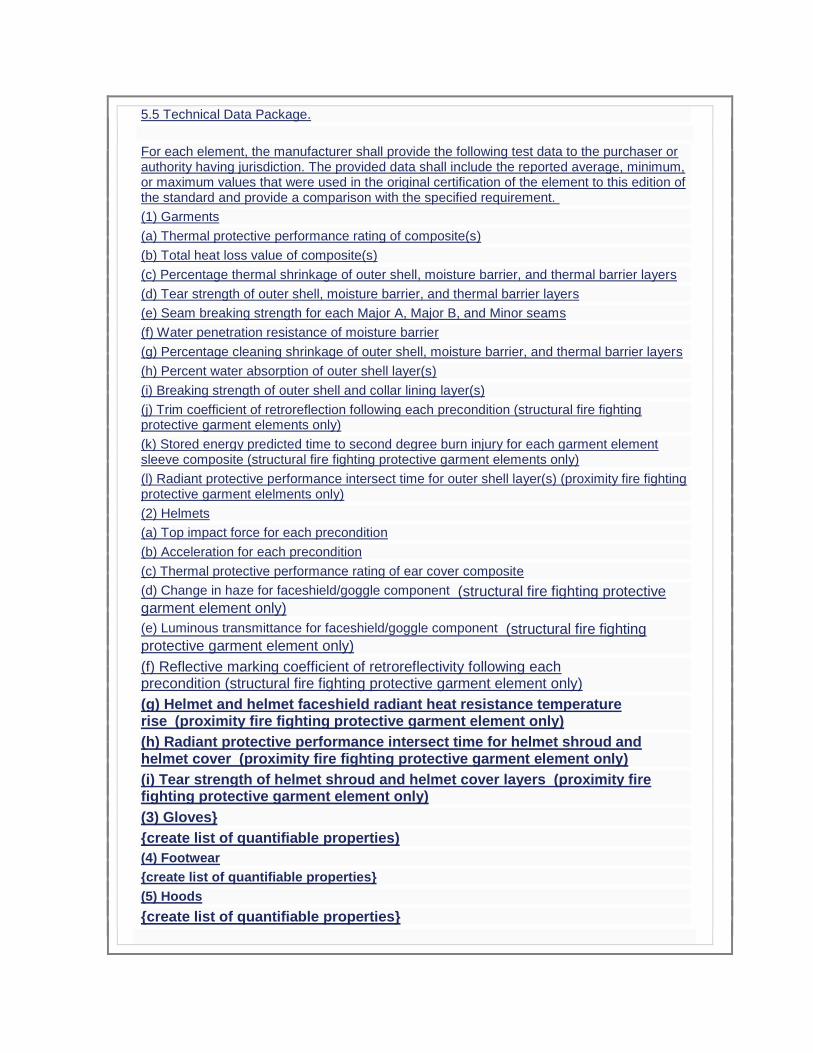
5.5 Technical Data Package.
For each element, the manufacturer shall provide the following test data to the purchaser or authority having jurisdiction. The provided data shall include the reported average, minimum, or maximum values that were used in the original certification of the element to this edition of the standard and provide a comparison with the specified requirement.
(1) Garments
(a) Thermal protective performance rating of composite(s)
(b) Total heat loss value of composite(s)
(c) Percentage thermal shrinkage of outer shell, moisture barrier, and thermal barrier layers
(d) Tear strength of outer shell, moisture barrier, and thermal barrier layers
(e) Seam breaking strength for each Major A, Major B, and Minor seams
(f) Water penetration resistance of moisture barrier
(g) Percentage cleaning shrinkage of outer shell, moisture barrier, and thermal barrier layers
(h) Percent water absorption of outer shell layer(s)
(i) Breaking strength of outer shell and collar lining layer(s)
(j) Trim coefficient of retroreflection following each precondition (structural fire fighting protective garment elements only)
(k) Stored energy predicted time to second degree burn injury for each garment element sleeve composite (structural fire fighting protective garment elements only)
(l) Radiant protective performance intersect time for outer shell layer(s) (proximity fire fighting protective garment elelments only)
(2) Helmets
(a) Top impact force for each precondition
(b) Acceleration for each precondition
(c) Thermal protective performance rating of ear cover composite
(d) Change in haze for faceshield/goggle component (structural fire fighting protective garment element only)
(e) Luminous transmittance for faceshield/goggle component (structural fire fighting protective garment element only)
(f) Reflective marking coefficient of retroreflectivity following each precondition (structural fire fighting protective garment element only)
(g) Helmet and helmet faceshield radiant heat resistance temperature rise (proximity fire fighting protective garment element only)
(h) Radiant protective performance intersect time for helmet shroud and helmet cover (proximity fire fighting protective garment element only)
(i) Tear strength of helmet shroud and helmet cover layers (proximity fire fighting protective garment element only)
(3) Gloves}
{create list of quantifiable properties)
(4) Footwear
{create list of quantifiable properties}
(5) Hoods
{create list of quantifiable properties}
Statement of Problem and Substantiation for Public Input
End users have difficulty comparing products and understanding voluminous product reports, which often rely on component recognition data from other suppliers not readily available to the manufacturer. The proposed provision of a technical data package captures quantifiable information on the respective elements that is based on the original certification values. This requirement has been established for other products within the project.
Submitter Information Verification
Submitter Full Name: JEFFREY STULL
Organization: INTERNATIONAL PERSONNEL PROTECTION, INC.
Street Address:
City:
State:
Zip:
Submittal Date: Mon Jul 06 05:38:21 EDT 2015
Public Input No. 191-NFPA 1971-2015 [ New Section after 5.4.6 ]
For helmets only, the manufacturer shall provide a list of items that meet the requirement, in addition to the items listed in 6.5.2, that are installed, attached, or packaged with the compliant helmet.
Statement of Problem and Substantiation for Public Input
The public input is being submitted on behalf of the helmet task group in an effort to address certification of accessory items that are installed, attached, or packaged with the helmet by the helmet manufacturer.
Submitter Information Verification
Submitter Full Name: TRICIA HOCK
Organization: SAFETY EQUIPMENT INSTITUTE SE
Street Address:
City:
State:
Zip:
Submittal Date: Thu Jul 02 13:22:17 EDT 2015

Public Input No. 205-NFPA 1971-2015 [ New Section after 6.1 ]
6.1.13
Liners that consist of thermal barriers sewn to moisture barrier, which are removable from the outer shell shall include an inspection opening that permits the examination of the lining interior, including all moisture barrier seams.
Statement of Problem and Substantiation for Public Input
NFPA 1851 specifies an advanced liner inspection that can only be accomplished by examining the liner interior. Without an inspection opening, the organization undertaking the inspection has to remove stitching to accomplish this inspection. Thus, an inspection opening facilitates any organization for being able to perform this inspection. The proposed requirement further permits the manufacturer to undertake a variety of design approaches to accomplish this feature.
Submitter Information Verification
Submitter Full Name: JEFFREY STULL
Organization: INTERNATIONAL PERSONNEL PROTECTION, INC.
Street Address:
City:
State:
Zip:
Submittal Date: Sat Jul 04 13:12:02 EDT 2015
Public Input No. 219-NFPA 1971-2015 [ Section No. 6.1.9.1 ]
6.1.9.1
Each coat element shall be permitted to have a DRD installed in the upper torso portion of the element.
6.1.9.1.1
The Where present, the DRD shall be accessible from the exterior of the garment.
6.1.9.1.2
The Where present, the DRD shall be easily accessible for deployment, shall be designed to minimize the risk of accidental deployment, and shall allow for visual inspection.
6.1.9.1.3
The Where present, the DRD shall be fully functional and shall not require any subsequent actions in order to be used, other than deploying the DRD, when the garment is donned in accordance with the manufacturer's instructions.
6.1.9.1.4
The Where present, the DRD shall be designed to allow deployment and operation of the DRD while the incapacitated fire fighter is wearing an SCBA.
6.1.9.1.5
The Where present, the DRD shall be designed so that when deployed, the DRD secures the fire fighter by the upper torso or shoulders so that the DRD pulls directly on the body and shall not pull only the garment.
Statement of Problem and Substantiation for Public Input
While the drag rescue device (DRD) was incorporated as a life-saving feature for protective coat, limited information is available to suggest that its use provides the intended benefits for rapid extraction of a downed firefighter that cannot be achieved by other means. Therefore, it is suggested that the DRD become optional and if absent, the manufacturer provide a warning that the organization establish specific procedures for the rapid extrication of downed firefighters by some other identified means. A public input has also been submitted to NFPA 1500 for fire departments to address this need as part of a required operating procedure.
Related Public Inputs for This Document
Related Input Relationship
Public Input No. 220-NFPA 1971-2015 [Section No. 8.57.1.1]
Public Input No. 221-NFPA 1971-2015 [Section No. 8.58.1]
Public Input No. 222-NFPA 1971-2015 [Sections 7.1.21, 7.1.22]
Public Input No. 223-NFPA 1971-2015 [New Section after 5.2.5]
Submitter Information Verification
Submitter Full Name: JEFFREY STULL
Organization: INTERNATIONAL PERSONNEL PROTECTION, INC.
Street Address:
City:
State:
Zip:
Submittal Date: Mon Jul 06 04:20:52 EDT 2015
Public Input No. 132-NFPA 1971-2015 [ Section No. 6.4 ]
6.4 Protective Helmet, Faceshield and Goggle Element Design Requirements for Both Ensembles.
6.4.1

Protective helmet elements shall have at least the applicable design requirements specified in this section where inspected and evaluated by the certification organization as specified in Section 4.3, Inspection and Testing.
6.4.2
No openings shall penetrate the helmet shell other than those provided by the manufacturer for mounting energy absorbing systems, retention systems, and accessories.
6.4.3
The helmet retention system shall include a chin strap and a nape device. The chin strap shall have a minimum width of 19 mm ( 3⁄4 in.).
6.4.4
All sewing thread used in the construction of helmets shall be made of inherently flame-resistant fiber.
6.4.5
The helmet faceshield or the faceshield/goggle component, when deployed, shall provide at least the following field of vision:
(1) Dihedral angle of at least 85 degrees
(2) Upper dihedral angle of at least 10 degrees
(3) Lower dihedral angle of at least 40 degrees
6.4.5.1
The field of vision shall be measured from the center of the eye.
6.4.5.2
The helmet with the faceshield or the faceshield/goggle component deployed shall be positioned in accordance with the HPI as described in 8.1.14 on a facial feature headform as defined in 3.3.43. Where the crown clearance of the helmet is adjustable, the helmet shall be mounted with the least amount of clearance.
8
6.4.6
The helmet faceshield or the faceshield/goggle component in the stowed position as described in
.1
.17 shall provide peripheral vision clearance of at least 94 degrees to each side.
6.4.6.1
The peripheral vision clearance shall be measured from the center of the eye, with the helmet positioned in accordance with the helmet positioning index (HPI) as described in 8.1.14 on a facial feature headform as defined in 3.3.43. Where the crown clearance of the helmet is adjustable, the helmet shall be mounted with the least amount of clearance.
6.4.7
Where helmets are provided with an SCBA facepiece that is attached or integrated with the helmet, the helmet with the SCBA facepiece installed shall meet all applicable design and performance requirements of this standard.
Statement of Problem and Substantiation for Public Input

The intent of this submittal is to remove faceshield/goggle/flip-down components from being externally attached to the helmet. Fire fighters are claiming neck and back injuries due to the “unbalanced” design of helmets. This has resulted in lawsuits against helmet manufacturers and dealers for neck and back injuries. Removal of externally mounted faceshield/goggle/flip-down components will minimize the “unbalance” issue. Faceshield/goggle/flip-down components, when externally mounted, provide additional safety and health hazards to fire fighters. These components are exposed to heat and physical damage during fire fighting and exposed to physical damage during other times. This causes the visibility through the components to be greatly compromised, often making visibility impossible. Goggles are exposed to the many carcinogens found in fire fighting and pose a health hazard when worn. Consequently, these components are almost never deployed and in many cases are removed from the helmet by the fire fighter. Most importantly, during structural fire fighting, face and eye protection should be provided by the SCBA mask, not a faceshield/goggle component. Faceshield/goggle components that are integrated into the helmet so they retract beneath the shell, when in the stowed position, should be allowed.
Submitter Information Verification
Submitter Full Name: ROBERT TUTTEROW
Organization: FIRE INDUSTRY EQUIPMENT RESEAR
Street Address:
City:
State:
Zip:
Submittal Date: Sat Jun 27 14:56:22 EDT 2015
Public Input No. 135-NFPA 1971-2015 [ Section No. 6.4.5 ]
6.4.5 Faceshield/goggle components shall meet thee respective requirements for goggles or faceshields and be marked "Z87 " in accordance with ANSI/ISEA Z87.1, Occupational and Educational Personal Eye and Face Protection Devices.
6.4.5.1 Faceshield/goggle components shall not be mounted externally of the helmet shell. Faceshield/goggle components that are stowed beneath the shell shall be permitted.
The helmet faceshield or the faceshield/goggle component, when deployed, shall provide at least the following field of vision:
(1) Dihedral angle of at least 85 degrees
(2) Upper dihedral angle of at least 10 degrees
(3) Lower dihedral angle of at least 40 degrees
6.4.5.1
The field of vision shall be measured from the center of the eye.
6.4.5.2
The helmet with the faceshield or the faceshield/goggle component deployed shall be positioned in accordance with the HPI as described in 8.1.14 on a facial feature headform as
defined in 3.3.43. Where the crown clearance of the helmet is adjustable, the helmet shall be mounted with the least amount of clearance.
Statement of Problem and Substantiation for Public Input
The intent of this submittal is to remove faceshield/goggle/flip-down components from being externally attached to the helmet. Fire fighters are claiming neck and back injuries due to the “unbalanced” design of helmets. This has resulted in lawsuits against helmet manufacturers and dealers for neck and back injuries. Removal of externally mounted faceshield/goggle/flip-down components will minimize the “unbalance” issue. Faceshield/goggle/flip-down components, when externally mounted, provide additional safety and health hazards to fire fighters. These components are exposed to heat and physical damage during fire fighting and exposed to physical damage during other times. This causes the visibility through the components to be greatly compromised, often making visibility impossible. Goggles are exposed to the many carcinogens found in fire fighting and pose a health hazard when worn. Consequently, these components are almost never deployed and in many cases are removed from the helmet by the fire fighter. Most importantly, during structural fire fighting, face and eye protection should be provided by the SCBA mask, not a faceshield/goggle component. Faceshield/goggle components that are integrated into the helmet so they retract beneath the shell, when in the stowed position, should be allowed.
Submitter Information Verification
Submitter Full Name: ROBERT TUTTEROW
Organization: FIRE INDUSTRY EQUIPMENT RESEAR
Street Address:
City:
State:
Zip:
Submittal Date: Sat Jun 27 15:12:08 EDT 2015
Public Input No. 170-NFPA 1971-2015 [ Section No. 6.4.6.1 ]
6.4.6.1
The peripheral vision clearance shall be measured from the center of the eye, with the helmet positioned in accordance with the helmet positioning index ( HPI ) as described in 8.1.14 on a facial feature headform as defined in 3.3.43. Where the crown clearance of the helmet is adjustable, the helmet shall be mounted with the least amount of clearance.
Statement of Problem and Substantiation for Public Input
Editorial. In the last edition the term "helmet positioning index" was simplified to "HPI" with a reference to a description in 8.1.14.
Submitter Information Verification
Submitter Full Name: ROBIN TUTOR
Organization: UL LLC
Street Address:
City:
State:
Zip:
Submittal Date: Wed Jul 01 08:50:35 EDT 2015
Public Input No. 188-NFPA 1971-2015 [ New Section after 6.4.7 ]
TITLE OF NEW CONTENT
6.4.8* For helmets with items installed or attached, the helmet with the items installed/attached shall meet the affected design and performance requirements of this standard.
Statement of Problem and Substantiation for Public Input
This is being submitted as TIA language that was approved by the TC and CC but has not been reviewed/approved by the Standards Council.
Related Public Inputs for This Document
Related Input Relationship
Public Input No. 189-NFPA 1971-2015 [New Section after A.6.2.4]
Submitter Information Verification
Submitter Full Name: TRICIA HOCK
Organization: SAFETY EQUIPMENT INSTITUTE SE
Street Address:
City:
State:
Zip:
Submittal Date: Thu Jul 02 13:05:58 EDT 2015
Public Input No. 99-NFPA 1971-2015 [ New Section after 6.4.7 ]
6.4.8* (NEW) For helmets with items installed or attached, the helmet with the items
installed/attached
shall meet the affected design and performance requirements of this standard.
A.6.4.8 Examples of items include, but are not limited to: (1) front holders for helmet
identification shields, (2) supplemental face shields and (3) other eye/face protection where
goggles are provided with the helmet as the required face shield/goggle component as identified
in 6.5.2.
Statement of Problem and Substantiation for Public Input
This was balloted as a TIA. Substantiation: The present NFPA 1971 language is unclear and could lead to various interpretations by certification organizations or other entities. This could allow manufacturers to solicit certifications that would favor their product. This will also clarify that the product, as received by the firefighter, is compliant with NFPA 1971. Emergency Nature: Currently the NFPA 1971 standard, 2013 edition contains an error and/or an omission that was overlooked during the regular revision process. The proposed language will correct this error. Current edition language is unclear that items attached to or integrated with the helmet as sold are to be included in tests. If these items are not included, users run the risk that these items can melt, drip, or ignite during firefighting operations, and can interfere with said operations or potentially cause a hazard to the user.
Submitter Information Verification
Submitter Full Name: STEVEN CORRADO
Organization: UL LLC
Street Address:
City:
State:
Zip:
Submittal Date: Tue May 19 08:59:40 EDT 2015
Public Input No. 217-NFPA 1971-2015 [ Section No. 6.5.2 ]
6.5.2*
Helmets shall consist of at least all of the following assembled components:
(1) Shell
(2) Energy absorbing system
(3) Retention system
(4) Fluorescent and retroreflective trim
(5) Ear covers
(6) A faceshield or goggles, or both
6.5.2.1
Where a faceshield is selected in accordance with 6.5.2 (6), the faceshield component shall be attached to the helmet.
6.5.2.2
Where the goggle component is selected in accordance with 6.5.2 (6), the goggles shall be permitted to be unattached, not assembled, to the helmet.
6.5.2.3
Where the manufacturer provides or intends to provide both a faceshield and goggles with the helmet, whether the faceshield is or is not provided installed or attached to the helmet, both the faceshield and the goggles shall be considered components of the helmet.
Statement of Problem and Substantiation for Public Input
A recent TIA to NFPA 1971-2013 attempted to reconcile differences between the testing practices of certification organizations but was over generalized to address the specific topic that created the issues in the first place. The proposed changes addresses the matter of an unqualified faceshield being used on a helmet when the manufacturer also provided goggles that are qualified as a component of the helmet.
Related Public Inputs for This Document
Related Input Relationship
Public Input No. 218-NFPA 1971-2015 [Section No. 8.6.12.2]
Submitter Information Verification
Submitter Full Name: JEFFREY STULL
Organization: INTERNATIONAL PERSONNEL PROTECTION, INC.
Street Address:
City:
State:
Zip:
Submittal Date: Mon Jul 06 04:07:05 EDT 2015
Public Input No. 133-NFPA 1971-2015 [ Section No. 6.5.2 [Excluding any Sub-Sections] ]
Helmets shall consist of at least all of the following assembled components:
(1) Shell
(2) Energy absorbing system
(3) Retention system
(4) Fluorescent and retroreflective trim
(5) Ear covers
(6) A faceshield or goggles, or both
Statement of Problem and Substantiation for Public Input
The intent of this submittal is to remove faceshield/goggle/flip-down components from being externally attached to the helmet. Fire fighters are claiming neck and back injuries due to the “unbalanced” design of helmets. This has resulted in lawsuits against helmet manufacturers and dealers for neck and back injuries. Removal of externally mounted faceshield/goggle/flip-down components will minimize the “unbalance” issue. Faceshield/goggle/flip-down components, when externally mounted, provide additional safety and health hazards to fire fighters. These components are exposed to heat and physical damage during fire fighting and exposed to physical damage during other times. This causes the visibility through the components to be greatly compromised, often making visibility impossible. Goggles are exposed to the many carcinogens found in fire fighting and pose a health hazard when worn. Consequently, these components are almost never deployed and in many cases are removed from the helmet by the fire fighter. Most importantly, during structural fire fighting, face and eye protection should be provided by the SCBA mask, not a faceshield/goggle component. Faceshield/goggle components that are integrated into the helmet so they retract beneath the shell, when in the stowed position, should be allowed.
Submitter Information Verification
Submitter Full Name: ROBERT TUTTEROW
Organization: FIRE INDUSTRY EQUIPMENT RESEAR
Street Address:
City:
State:
Zip:
Submittal Date: Sat Jun 27 15:03:22 EDT 2015
Public Input No. 134-NFPA 1971-2015 [ Sections 6.5.2.1, 6.5.2.2 ]
Sections 6.5.2.1, 6.5.2.2
6.5.2.1
Where a faceshield is selected in accordance with 6.5.2 (6), the faceshield component shall be attached to the helmet.
6.5.2.2

Where the goggle component is selected in accordance with 6.5.2 (6), the goggles shall be permitted to be unattached, not assembled, to the helmet.
Statement of Problem and Substantiation for Public Input
The intent of this submittal is to remove faceshield/goggle/flip-down components from being externally attached to the helmet. Fire fighters are claiming neck and back injuries due to the “unbalanced” design of helmets. This has resulted in lawsuits against helmet manufacturers and dealers for neck and back injuries. Removal of externally mounted faceshield/goggle/flip-down components will minimize the “unbalance” issue. Faceshield/goggle/flip-down components, when externally mounted, provide additional safety and health hazards to fire fighters. These components are exposed to heat and physical damage during fire fighting and exposed to physical damage during other times. This causes the visibility through the components to be greatly compromised, often making visibility impossible. Goggles are exposed to the many carcinogens found in fire fighting and pose a health hazard when worn. Consequently, these components are almost never deployed and in many cases are removed from the helmet by the fire fighter. Most importantly, during structural fire fighting, face and eye protection should be provided by the SCBA mask, not a faceshield/goggle component. Faceshield/goggle components that are integrated into the helmet so they retract beneath the shell, when in the stowed position, should be allowed.
Submitter Information Verification
Submitter Full Name: ROBERT TUTTEROW
Organization: FIRE INDUSTRY EQUIPMENT RESEAR
Street Address:
City:
State:
Zip:
Submittal Date: Sat Jun 27 15:09:13 EDT 2015
Public Input No. 216-NFPA 1971-2015 [ Section No. 6.5.4 ]
6.5.4
Helmet ear covers or the portion of the helmet providing the coverage of the ears, when deployed, shall provide at least the following coverage:
(1) 95 mm (3 3⁄4 in.) measured 50 mm (2 in.) forward of the coronal plane
(2) 120 mm (4 3⁄4 in.) measured 25 mm (1 in.) forward of the coronal plane
(3) 130 mm (5 1⁄8 in.) measured at the coronal plane
(4) 130 mm (5 1⁄8 in.) measured at the midsagittal plane at the rear of the headform
6.5.4.1
The helmet, with the ear covers or the portion of the helmet providing the ear coverage deployed, shall be positioned according to the HPI as described in 8.1.14 on an ISO J
headform. Where the crown clearance of the helmet is adjustable, the helmet shall be mounted with the most amount of clearance.
6.5.4.2
In this position, the ear coverage shall be measured downward from the reference plane to the lower edge of the ear coverage at the specified points to determine the coverage specified in 6.5.4.
6.5.4.3
Where the helmet incorporates a ratchet-style headband, an opening in the covering surrounding the ratchet knob shall be permitted. The opening shall not extend more than 13 mm ( 1⁄2 in.) in any direction around the perimeter of the adjustment device.
6.5.4.4
The method for the attachment of ear covers to the helmet shall allow for their easy detachment and reattachment to permit cleaning within a period of 2 minutes.
Statement of Problem and Substantiation for Public Input
Provisions are made in NFPA 1851 for the detachment and separate cleaning of components that can be removed from helmets as part of advanced cleaning. Ear covers represent a portion of helmets that can be easily soiled on the fireground and for which cleaning is best undertaken separately. The proposed requirement for their easy removal and reinstallation facilities more frequent cleaning of this element component.
Submitter Information Verification
Submitter Full Name: JEFFREY STULL
Organization: INTERNATIONAL PERSONNEL PROTECTION, INC.
Street Address:
City:
State:
Zip:
Submittal Date: Mon Jul 06 03:56:06 EDT 2015
Public Input No. 171-NFPA 1971-2015 [ Section No. 6.5.4.1 ]
6.5.4.1
The helmet, with the ear covers or the portion of the helmet providing the ear coverage deployed, shall be positioned according to the HPI as described in 8.1.14 on an ISO size J headform as specified in Figure 8.16.4.1. Where the crown clearance of the helmet is adjustable, the helmet shall be mounted with the most amount of clearance.
Statement of Problem and Substantiation for Public Input
Editorial. Adding the same specifications/reference for the ISO size J headform that are used throughout the remainder of the standard.
Submitter Information Verification
Submitter Full Name: ROBIN TUTOR
Organization: UL LLC
Street Address:
City:
State:
Zip:
Submittal Date: Wed Jul 01 08:59:54 EDT 2015
Public Input No. 136-NFPA 1971-2015 [ Section No. 6.5.5 ]
6.5.5
Faceshield/goggle components shall meet the respective requirements for goggles or faceshields and be marked “Z87+” in accordance with ANSI/ISEA Z87.1, Occupational and Educational Personal Eye and Face Protection Devices.
Statement of Problem and Substantiation for Public Input
This text was moved to earlier in the chapter by another input. The intent of this submittal is to remove faceshield/goggle/flip-down components from being externally attached to the helmet. Fire fighters are claiming neck and back injuries due to the “unbalanced” design of helmets. This has resulted in lawsuits against helmet manufacturers and dealers for neck and back injuries. Removal of externally mounted faceshield/goggle/flip-down components will minimize the “unbalance” issue. Faceshield/goggle/flip-down components, when externally mounted, provide additional safety and health hazards to fire fighters. These components are exposed to heat and physical damage during fire fighting and exposed to physical damage during other times. This causes the visibility through the components to be greatly compromised, often making visibility impossible. Goggles are exposed to the many carcinogens found in fire fighting and pose a health hazard when worn. Consequently, these components are almost never deployed and in many cases are removed from the helmet by the fire fighter. Most importantly, during structural fire fighting, face and eye protection should be provided by the SCBA mask, not a faceshield/goggle component. Faceshield/goggle components that are integrated into the helmet so they retract beneath the shell, when in the stowed position, should be allowed.
Submitter Information Verification
Submitter Full Name: ROBERT TUTTEROW
Organization: FIRE INDUSTRY EQUIPMENT RESEAR
Street Address:
City:
State:
Zip:
Submittal Date: Sat Jun 27 15:23:18 EDT 2015
Public Input No. 172-NFPA 1971-2015 [ New Section after 6.6.5.1 ]
6.6.5.1.1 The helmet, with the shroud deployed, shall be positioned according to the HPI as
described in 8.1.14 on an ISO size J headform as specified in Figure 8.16.4.1. Where the crown clearance of the helmet is adjustable, the helmet shall be mounted with the most amount of clearance.
6.6.5.1.2 In this position, the shroud coverage shall be measured downward from the
reference plane to the lower edge of the shroud coverage at the specified points to determine the coverage specified in 6.6.5.1.
Statement of Problem and Substantiation for Public Input
Providing instructions as to how the helmet is to be positioned and measured when determining shroud coverage. This is the same wording that is given for measuring ear coverage in 6.5.4.
Submitter Information Verification
Submitter Full Name: ROBIN TUTOR
Organization: UL LLC
Street Address:
City:
State:
Zip:
Submittal Date: Wed Jul 01 09:13:33 EDT 2015
Public Input No. 66-NFPA 1971-2015 [ Section No. 6.7.3.5.2 ]
6.7.3.5.2
A 1 lb weight shall be attached to the end of the glove body, gauntlet glove interface component, or glove extension. The weight shall not be attached to a knitted wristlet glove interface component. The weight shall be applied evenly across the glove.
Statement of Problem and Substantiation for Public Input
Technical Committee agreed to remove the term gauntlet in the previous edition. See ROC Log 128 (1971-2)
Submitter Information Verification
Submitter Full Name: Michael McKenna
Organization: Michael McKenna & Associates,
Street Address:
City:
State:
Zip:
Submittal Date: Wed Apr 01 13:38:05 EDT 2015
Public Input No. 127-NFPA 1971-2015 [ Section No. 6.7.6 [Excluding any Sub-Sections] ]
In order to label or otherwise represent a glove as compliant with the requirements of this standard, the manufacturer shall provide gloves in the following sizes:
(1) Extra, extra small (XXS64 N (Normal)
(2) Extra small 70 N (XSNormal)
(3) Small 70 W (SWide)
(4) Medium 76 N (MNormal)
(5) Large 76 W (LWide)
(6) Extra large 80 N (XLNormal)
(7) Extra, extra large (XXL80 W (Wide)
Statement of Problem and Substantiation for Public Input
Please reference our presentation from the the Hartford meeting. The current sizing system is confusing to all firefighters and does not address the needs of female firefighters who have narrow hands. The current NFPA 1971 sizing has many problems including: 1) the size ranges overlap leading to confusion. For example, the D2 (Index) finger length of 7.0 cm falls within the range Small, Medium, and Large sizes--manufacturers could label such a glove any of these three sizes and meet the requirement. 2) The size ranges are not evenly graded. For example, the Medium size finger lengths are much closer to the Small than the Large 3) Narrow sizes for a significant segment of the female firefighter population are not defined 4) "Cadet" sizing for a significant segment of the male firefighter population with wider palms are not defined The proposed sizing system overcomes these problems and features an evenly graded system that readily lends itself to the use of a Brannock-style measuring device for estimating correct sizing (similar to footwear)
Related Public Inputs for This Document
Related Input Relationship
Public Input No. 128-NFPA 1971-2015 [Section No. 6.7.6.1]
Public Input No. 129-NFPA 1971-2015 [Section No. 6.7.6.2]
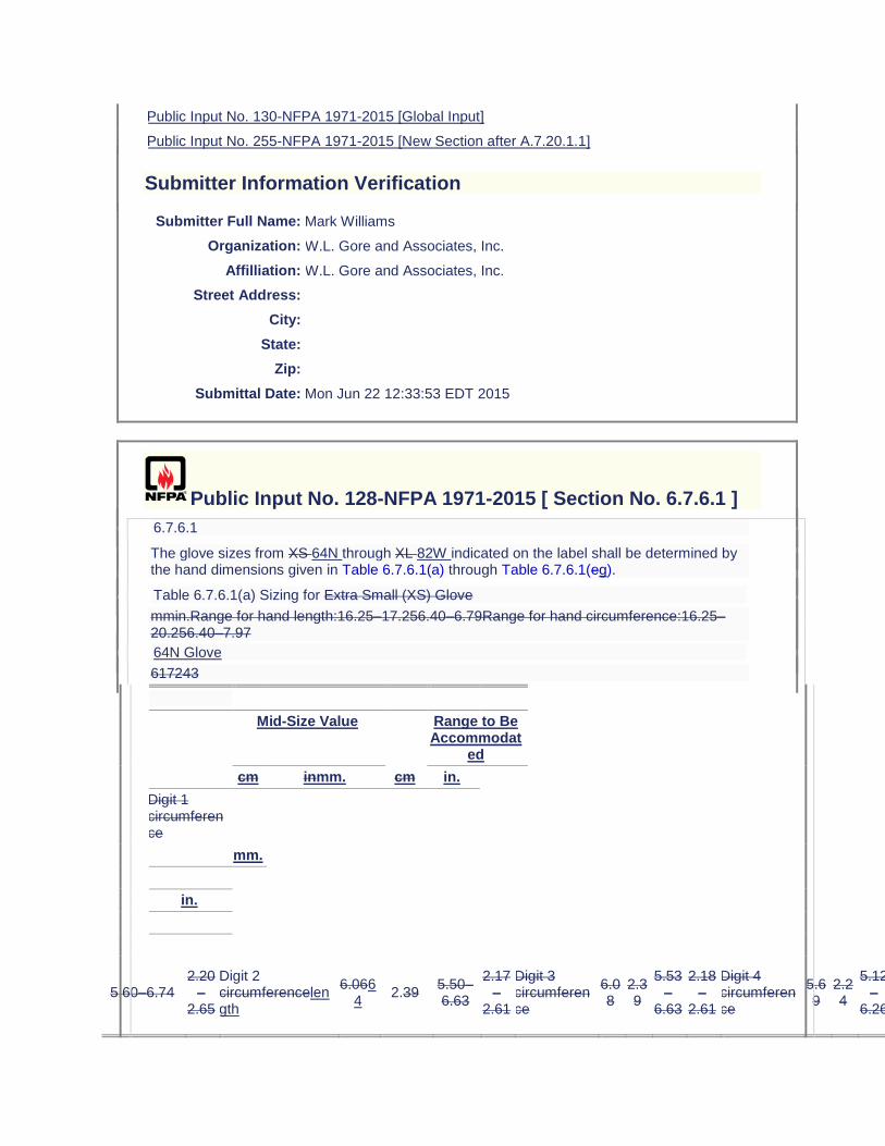
Public Input No. 130-NFPA 1971-2015 [Global Input]
Public Input No. 255-NFPA 1971-2015 [New Section after A.7.20.1.1]
Submitter Information Verification
Submitter Full Name: Mark Williams
Organization: W.L. Gore and Associates, Inc.
Affilliation: W.L. Gore and Associates, Inc.
Street Address:
City:
State:
Zip:
Submittal Date: Mon Jun 22 12:33:53 EDT 2015
Public Input No. 128-NFPA 1971-2015 [ Section No. 6.7.6.1 ]
6.7.6.1
The glove sizes from XS 64N through XL 82W indicated on the label shall be determined by the hand dimensions given in Table 6.7.6.1(a) through Table 6.7.6.1(eg).
Table 6.7.6.1(a) Sizing for Extra Small (XS) Glove
mmin.Range for hand length:16.25–17.256.40–6.79Range for hand circumference:16.25–20.256.40–7.97
64N Glove
617243
Mid-Size Value Range to Be Accommodat
ed
cm inmm. cm in.
Digit 1 circumference
mm.
in.
5.60–6.74 2.20
–2.65
Digit 2 circumferencelength
6.0664
2.39 5.50–6.63
2.17–
2.61
Digit 3 circumference
6.08
2.39
5.53–
6.63
2.18–
2.61
Digit 4 circumference
5.69
2.24
5.12–
6.26
2.02–
2.46
Digit 5 circumference
5.00
1.97
4.48–
5.52
1.76–
2.17
Digit 1 length
4.94
1.94
4.36–
5.52
1.72–
2.17
Digit 2 length
6.44
2.54
5.75–
7.12
2.26–
2.80
Digit 3 length
7.29
2.87
6.71–
7.87
2.64–
3.10
Digit 4 length
6.78
2.67
6.13–
7.42
2.41–
2.92
Digit 5 length
5.09
2.00
4.52–
5.66
1.78–
2.23
Hand circumference
18.25
7.19
16.34–
20.16
6.43–
7.94
Hand length
16.75
6.59
16.27–
17.23
6.41–
6.78
52
61-
67
2.64–
2.87
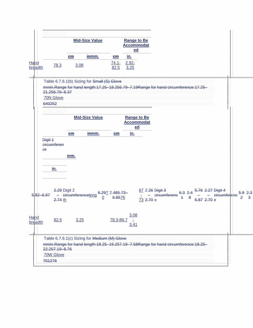
Mid-Size Value Range to Be Accommodat
ed
cm inmm. cm in.
Hand breadth
78.3 3.08 74.1-82.5
2.92-3.25
Table 6.7.6.1(b) Sizing for Small (S) Glove
mmin.Range for hand length:17.25–18.256.79–7.19Range for hand circumference:17.25–21.256.79–8.37
70N Glove
640252
Mid-Size Value Range to Be Accommodat
ed
cm inmm. cm in.
Digit 1 circumference
mm.
in.
5.82–6.97 2.29
–2.74
Digit 2 circumferencelength
6.2970
2.485.73–6.8576
67-
73
2.26–
2.70
Digit 3 circumference
6.31
2.48
5.76–
6.87
2.27–
2.70
Digit 4 circumference
5.92
2.33
5.35–
6.49
2.11–
2.56
Digit 5 circumference
5.22
2.06
4.70–
5.74
1.85–
2.26
Digit 1 length
5.31
2.09
4.74–
5.89
1.87–
2.32
Digit 2 length
6.89
2.71
6.21–
7.57
2.44–
2.98
Digit 3 length
7.71
3.04
7.13–
8.30
2.81–
3.27
Digit 4 length
7.19
2.83
6.55–
7.03
2.58–
3.08
Digit 5 length
5.44
2.14
4.87–
6.01
1.92–
2.37
Hand circumference
19.25
7.58
17.34–
21.16
6.83–
8.33
Hand length
17.75
6.99
17.27–
18.23
6.80–
7.18
64-2.87
Hand breadth
82.5 3.25 78.3-86.7 3.08
-3.41
Table 6.7.6.1(c) Sizing for Medium (M) Glove
mmin.Range for hand length:18.25–19.257.19–7.58Range for hand circumference:18.25–22.257.19–8.76
70W Glove
701276
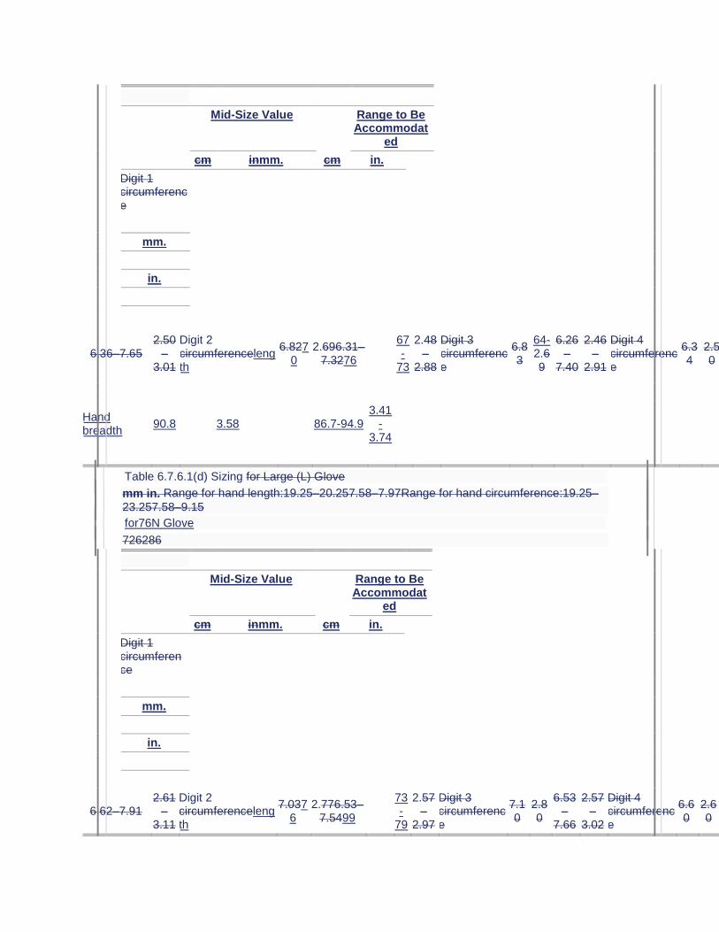
Mid-Size Value Range to Be Accommodat
ed
cm inmm. cm in.
Digit 1 circumference
mm.
in.
6.36–7.65 2.50
–3.01
Digit 2 circumferencelength
6.8270
2.696.31–7.3276
67-
73
2.48–
2.88
Digit 3 circumference
6.83
64-2.69
6.26–
7.40
2.46–
2.91
Digit 4 circumference
6.34
2.50
5.78–
6.90
2.28–
2.72
Digit 5 circumference
5.63
2.22
5.09–
6.17
2.00–
2.43
Digit 1 length
5.63
2.22
5.00–
6.26
1.97–
2.46
Digit 2 length
7.11
2.80
6.50–
7.72
2.56–
3.04
Digit 3 length
8.07
3.18
7.55–
8.58
2.97–
3.38
Digit 4 length
7.61
3.00
7.14–
8.08
2.81–
3.18
Digit 5 length
5.78
2.28
5.16–
6.41
2.03–
2.52
Hand circumference
20.25
7.97
18.34–
22.16
7.22–
8.72
Hand length
18.75
7.38
18.27–
19.23
7.19–
7.57
87
Hand breadth
90.8 3.58 86.7-94.9 3.41
-3.74
Table 6.7.6.1(d) Sizing for Large (L) Glove
mm in. Range for hand length:19.25–20.257.58–7.97Range for hand circumference:19.25–
23.257.58–9.15
for76N Glove
726286
Mid-Size Value Range to Be Accommodat
ed
cm inmm. cm in.
Digit 1 circumference
mm.
in.
6.62–7.91 2.61
–3.11
Digit 2 circumferencelength
7.0376
2.776.53–7.5499
73-
79
2.57–
2.97
Digit 3 circumference
7.10
2.80
6.53–
7.66
2.57–
3.02
Digit 4 circumference
6.60
2.60
6.04–
7.16
2.38–
2.82
Digit 5 circumference
5.85
2.30
5.31–
6.39
2.09–
2.52
Digit 1
5.87
2.31
5.24–
6.50
2.06–
2.56
Digit 2
7.49
2.95
6.88–
8.10
2.71–
3.19
Digit 3
8.54
3.36
8.03–
9.06
3.16–
3.57
Digit 4
8.03
3.16
7.56–
8.50
2.98–
3.35
Digit 5
6.13
2.41
5.51–
6.75
2.17–
2.66
Hand circumference
21.25
8.37
19.34–
23.16
7.61–
9.12
Hand length
19.75
7.78
19.27–
20.23
7.59–
7.96
87-3.11

Mid-Size Value Range to Be Accommodat
ed
cm inmm. cm in.
length
length
length
length
length
Hand breadth
86.9 3.42 82.9-90.9 3.26
-3.58
Table 6.7.6.1(e) Sizing for 76W Glove
Mid-Size Value Range to Be Accommodated
mm. in. mm. in.
Digit 2 length 76 2.99 73-79 2.87-3.11
Hand breadth 94.9 3.74 90.9-98.9 3.58-3.89
Table 6.7.6.1(
e
f) Sizing for
Extra-Large (XL) Glove mm in. Range for hand length:20.25–21.257.97–8.37Range for hand
circumference:20.25–24.257.97–9.55
82N Glove
Mid-Size Value Range to Be Accommodated
cm
mm. in.
cm
mm. in.
Digit
1 circumference7.522.966.87–8.162.70–3.21Digit 2 circumference7.252.856.74–7.762.65–3.06Digit 3 circumference7.362.906.79–7.932.67–3.12Digit 4 circumference6.862.706.30–7.422.48–2.92Digit 5 circumference6.062.395.52–6.602.17–2.60Digit 1 length6.112.415.48–6.752.16–2.66Digit 2 length7.863.097.26–8.472.86–3.33Digit 3 length9.023.558.51–9.543.35–3.76Digit 4 length8.443.327.97–8.913.14–3.51Digit 5 length6.482.555.85–7.102.30–2.80Hand circumference22.258.7620.34–24.168.01–9.51Hand length20.758.1720.27–21.237.98–8.36
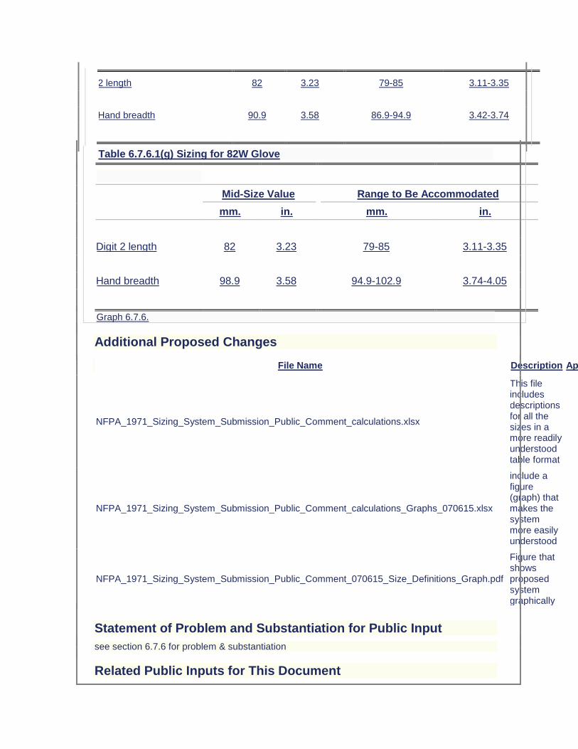
2 length 82 3.23 79-85 3.11-3.35
Hand breadth 90.9 3.58 86.9-94.9 3.42-3.74
Table 6.7.6.1(g) Sizing for 82W Glove
Mid-Size Value Range to Be Accommodated
mm. in. mm. in.
Digit 2 length 82 3.23 79-85 3.11-3.35
Hand breadth 98.9 3.58 94.9-102.9 3.74-4.05
Graph 6.7.6.
Additional Proposed Changes
File Name Description Approved
NFPA_1971_Sizing_System_Submission_Public_Comment_calculations.xlsx
This file includes descriptions for all the sizes in a more readily understood table format
NFPA_1971_Sizing_System_Submission_Public_Comment_calculations_Graphs_070615.xlsx
include a figure (graph) that makes the system more easily understood
NFPA_1971_Sizing_System_Submission_Public_Comment_070615_Size_Definitions_Graph.pdf
Figure that shows proposed system graphically
Statement of Problem and Substantiation for Public Input
see section 6.7.6 for problem & substantiation
Related Public Inputs for This Document
Related Input Relationship
Public Input No. 127-NFPA 1971-2015 [Section No. 6.7.6 [Excluding any Sub-Sections]]
table supporting original comment
Submitter Information Verification
Submitter Full Name: Mark Williams
Organization: W.L. Gore & Associates, Inc.
Affilliation: W.L. Gore & Associates, Inc.
Street Address:
City:
State:
Zip:
Submittal Date: Tue Jun 23 16:33:33 EDT 2015
Public Input No. 129-NFPA 1971-2015 [ Section No. 6.7.6.2 ]
6.7.6.2
The sizes for XXS shall be smaller than the sizing indicated in Table 6.7.6.1(a), and Size XXL shall be larger than sizes indicated in Table 6.7.6.1(e).
Statement of Problem and Substantiation for Public Input
see 6.7.6 for substantiation This sentence no longer necessary
Related Public Inputs for This Document
Related Input Relationship
Public Input No. 127-NFPA 1971-2015 [Section No. 6.7.6 [Excluding any Sub-Sections]]
sentence no longer needed
Submitter Information Verification
Submitter Full Name: Mark Williams
Organization: W.L. Gore & Associates, Inc.
Affilliation: W.L. Gore & Associates, Inc.
Street Address:
City:
State:
Zip:
Submittal Date: Tue Jun 23 17:54:38 EDT 2015
Public Input No. 228-NFPA 1971-2015 [ Section No. 6.10.3 ]
6.10.3
Footwear height shall be a minimum of 250 255 mm (10 in.).
6.10.3.1
The footwear height shall be determined by measuring inside the footwear from the center of the insole at the heel up to a perpendicular reference line extending across the footwear at the lowest point of the top line, excluding the tongue and gusset.
6.10.3.2
Removable insoles shall not be removed prior to measurement.
6.10.3.3
Thermal, physical, and moisture protection shall be continuous circumferentially to within 50 mm (2 in.) of the footwear top line at all locations, with the exception of the area inside of and within 13 mm ( 1⁄2 in.) around pull-up holes that fully penetrate the footwear from outside to inside. The height of thermal, physical, and moisture protection at all locations of the boot shall be no less than 25.4 cm 255 mm (10 in.) when measured as described in 6.10.3.1.
Statement of Problem and Substantiation for Public Input
Editorial. Correcting conversion, using the same number/units for both 6.10.3 and 6.10.3.3, and rounding to the nearest 5 mm as is consistent with other conversions.
Submitter Information Verification
Submitter Full Name: ROBIN TUTOR
Organization: UL LLC
Street Address:
City:
State:
Zip:
Submittal Date: Mon Jul 06 11:15:06 EDT 2015
Public Input No. 35-NFPA 1971-2014 [ New Section after 6.11 ]
Recommendation for structural fire boots.
I propose an NFPA recommendation, not a requirement, that fire boots have some kind
of illumination. In 2011 I was conducting a search for a suspected lost victim at a structure
fire and a ceiling collapsed on myself and another firefighter. Visibility was terrible, and that made the dangerous situation far worse. My gear saved my life or at the very least kept me from being seriously hurt. Searching for victims is one of the most stressful and dangerous tasks that a firefighter performs. Life safety is our primary focus, and searching and rescuing victims is the top priority.
We are taught to never conduct a search alone, and we stay together by holding or at least keeping a visual of the ankle of the firefighter crawling in front of you. Too much focus is on just trying to stay together, and we are less effective at the task of searching and rescuing. Since being involved in the collapse, I have been thinking of ways to improve the safety and effectiveness of firefighters while searching. I believe part of the problem is a complete lack of visibility on the lower portion of a firefighters body, and also the lack of a rear facing light source. The most logical place to incorporate lights into the gear is down low, and the boots are a perfect location. The lights will at the very least be located in the heel facing backwards. Lights may also be located towards the front for added visibility.
The lights are not intended to be too bright, more of an awareness strength with approximately one or two steps of outward light. The purpose is mainly to better be seen, but it will also illuminate a small area around the firefighter, which will light up any hazards as well as ensure that the firefighter will always have a light source on them.This feature will increase safety for firefighters conducting searches, operating on roofs, ascending and descending dark stairways, operating on roadways, and operating in any space where visibility is low. This feature will also help other firefighters locate lost or injured firefighters. Good for RIT teams.
So to summarize my proposal: I am hoping we can incorporate language that just recommends a light source within structural fire boots. I am not seeking any kind of
requirement, but I believe it is worthy of a recommendation. Having a fixed light source, rear facing, low to the ground, can only improve safety and firefighter effectiveness. I have been in many situations where I know that illuminated fire boots would have been a significant help. I have shared this concept with over 50 firefighters and they were all very excited about the prospect of having lights in their boots. Illuminated fire boots are in the design process by two company's that make the best fire boot outsole, and fire lights. We will see them in a year or so, and an NFPA recommendation makes sense to me in this case. Just a few basic sentences in the new edition I believe will help the concept, and it is the evolution of fire boots. It is a worthy safety increase, and I hope we can have some simple NFPA language. Firefighters will always need boots and lights, and for safety, visibility, and firefighter performance this is the future of fire boots. If illuminated boots can save one life it is worth it. I can bring in examples to show what illuminated fire boots can do if the committee would like to see them first hand.
Thank you,
FF Scott Austin
Additional Proposed Changes
File Name Description Approved
DSC05718.JPG firefighter crawling with illuminated fire boots.
DSC05716.JPG Firefighter walking with Illuminated fire boots
DSC05728.JPG firefighter on roof with illuminated fire boots
Statement of Problem and Substantiation for Public Input
A problem facing firefighters is poor visibility. As we all know firefighters operate under very dark hazardous conditions. Firefighters are often disoriented, lost, trapped, or killed, and part of the reason is poor visibility. We currently do not have a light source that is rear facing and below chest height. Firefighters have typical flashlights on their helmets or attached to their coat. These lights are useful, but not as useful as having lights built into fire boots. Typical lights are only forward facing, can be lost, or handed off to someone else leaving the firefighter without his light source. The light we bring into a fire is all we have, and it can be the difference between life and death. I am proposing NFPA language that only recommends illuminated fire boots. It is a fixed light source, low to the ground, and serves many purposes. An increase in firefighter visibility is always a step forward in terms of safety and firefighter performance. Having lights fixed into the boot will ensure the firefighter always has a light source and increased visibility. Illuminated fire boots will help solve visibility problems, especially while conducting searches. I am not seeking a requirement, only language that states that the NFPA recommends a light source within the fire boot for increased visibility where it is needed most. Something like that. thank you
Submitter Information Verification
Submitter Full Name: scott austin
Organization: Tewksbury Fire dept.
Street Address:
City:
State:
Zip:
Submittal Date: Thu Jun 05 07:54:42 EDT 2014
Public Input No. 138-NFPA 1971-2015 [ New Section after 6.13.3.1 ]
TITLE OF NEW CONTENT
Type your content here ...Hoods shall be permitted to be integrated with the protective helmet.
Statement of Problem and Substantiation for Public Input
Hoods are permitted to be integrated with the protective coat. They should also be allowed to be integrated with the helmet. This is especially viable with "European" style helmets. Head and neck protection is not compromised if this is permitted and donning/doffing is much quicker.
Submitter Information Verification
Submitter Full Name: ROBERT TUTTEROW
Organization: FIRE INDUSTRY EQUIPMENT RESEAR
Street Address:
City:
State:
Zip:
Submittal Date: Sat Jun 27 15:34:52 EDT 2015
Public Input No. 107-NFPA 1971-2015 [ Section No. 6.13.6.1 ]
6.13.6.1
Other than where the hood face opening is designed to interface with a specific SCBA facepiece, the hood face opening shall measure 145 mm, +0/–25 mm (5 5⁄8 in., +0/–1 in.) in any direction when the hood is laid out in a relaxed condition on a flat surface, smoothed out, and with the face opening facing upward.
Additional Proposed Changes
File Name Description Approved
Face_Opening_Measurements_of_Hoods.docx Hood task group summary
Statement of Problem and Substantiation for Public Input
See attached task group summary. This requirement is being deleted since it is being added to a pre-test requirement in the Cleaning Shrinkage Resistance test.
Related Public Inputs for This Document
Related Input Relationship
Public Input No. 108-NFPA 1971-2015 [Section No. 8.24.9.3]
Public Input No. 109-NFPA 1971-2015 [New Section after 8.24.9.3]
Public Input No. 110-NFPA 1971-2015 [Section No. 8.24.9.5]
Public Input No. 111-NFPA 1971-2015 [Section No. 8.24.9.6]
Public Input No. 112-NFPA 1971-2015 [Section No. 8.24.9.7]
Public Input No. 113-NFPA 1971-2015 [Section No. 8.24.9.8]
Public Input No. 114-NFPA 1971-2015 [Section No. 8.24.9.10]
Public Input No. 115-NFPA 1971-2015 [Section No. 8.24.9.12]
Public Input No. 116-NFPA 1971-2015 [Section No. 8.24.9.14]
Public Input No. 117-NFPA 1971-2015 [Sections 8.46.4.2, 8.46.4.3, 8.46.4.4, 8.46.4.5, 8.46.4.6, ...]
Public Input No. 118-NFPA 1971-2015 [Section No. 8.46.6]
Public Input No. 119-NFPA 1971-2015 [Section No. 8.46.8]
Public Input No. 120-NFPA 1971-2015 [Section No. 8.6.16]
Public Input No. 121-NFPA 1971-2015 [Section No. 7.13.1 [Excluding any Sub-Sections]]
Public Input No. 122-NFPA 1971-2015 [Section No. 7.13.4]
Public Input No. 123-NFPA 1971-2015 [Section No. 7.13.6]
Submitter Information Verification
Submitter Full Name: AMANDA NEWSOM
Organization: UL LLC
Street Address:
City:
State:
Zip:
Submittal Date: Mon Jun 08 11:15:33 EDT 2015
Public Input No. 242-NFPA 1971-2015 [ Section No. 6.18 ]
6.18 Reserved. Optional Protective Particulate Barrier Hood Interface Component Design Requirements .
6.18.1
The particulate barrier hood interface component shall meet the all the requirements specified in Section 6.13, but shall be design with a face opening that is designed to interface with a specific SCBA facepiece as specified in 6.13.6.3.
6.18.2
The portions of the particulate barrier hood interface component that include a barrier material specifically for meeting the requirements of 7.14.1 shall include all areas of the hood to at least 75 mm (3 in.) above the reference plane and all areas of the hood to at least 75 mm (3 in.) below the reference plane as measured when the hood is placed on an ISO Size J headform.
6.18.3
Binding around the hood face opening shall be permitted to exclude barrier material specifically for meeting the requirements of 7.14.1 for a distance of 6 mm (1/4 inch) from the inner edge of the hood face opening.
It is recommended that this section be renumbered as 6.14 and that current sections 6.15, 6.16, and 6.17, be renumbered as 6.16, 6.17, and 6.18, respectively.
Statement of Problem and Substantiation for Public Input
Protective hoods currently do not require any form of a barrier layer and the majority of protective hoods in the market place are fabricated of two or more layers of an open knit that readily allows smoke and contaminant particles to pass through the hood materials and deposit on the wearer’s skin. Optional requirements for a hood are proposed that define a barrier that limits the passage of particulates as addressed by both design and performance requirements. The proposed changes in this input provide recommended design requirements for an optional particular barrier hood interface component. A white paper on this topic is attached.
Related Public Inputs for This Document
Related Input Relationship
Public Input No. 246-NFPA 1971-2015 [New Section after 1.1.2] Parent Log
Submitter Information Verification
Submitter Full Name: JEFFREY STULL
Organization: INTERNATIONAL PERSONNEL PROTECTION, INC.
Street Address:
City:
State:
Zip:
Submittal Date: Mon Jul 06 14:20:44 EDT 2015
Public Input No. 262-NFPA 1971-2015 [ New Section after 7.1 ]
Maximum amount of additoal accessories
Where the total surface area of all reinforcements exceeds 65% of the garment, the reinforcement composites shall be tested for evaporative heat transfer as specified in Section 8.5, Total Heat Loss Test, and shall have a total heat loss of not less than 205 W/m2.
Statement of Problem and Substantiation for Public Input
Many studies have shown the correlations between material level THL and the physiological impact on firefighters. However, in all these studies the garment design has always been the same and no one has tested a garment with the same materials but with different levels of added protection added to the suit. NCSU has evaluated two suits with the same base composite (THL 263 w/m2) on the sweating manikin system. The differences in the suits were the amount of additional material added for pockets and additional protection. One suit had the minimum amount of protection required by NFPA 1971 while the second suit had the amount added by a current department in the USA (only 33% of the suit was the base composite). Results from the manikin were significantly different. When this data was used in a model there was also an estimated increase in core temperature of ~0.6 oC after a 90 minute moderate amount of exercise in a moderate environment (21 C, 50% RH). I am asking the committee to consider this requirement to prevent suits from being bulked up and increasing heat stress on the firefighter. This is a similar requirement found in NFPA 1977. It was also introduced for the same reason.
Submitter Information Verification
Submitter Full Name: Anthoney Deaton
Organization: NC State University
Street Address:
City:
State:
Zip:
Submittal Date: Mon Jul 06 20:35:48 EDT 2015
Public Input No. 125-NFPA 1971-2015 [ Section No. 7.1.2 ]
7.1.2
Garments shall be tested for overall liquid penetration resistance as specified in Section 8.47, Whole Garment and Ensemble Liquid Penetration Test, and shall allow no liquid penetration.
Statement of Problem and Substantiation for Public Input
Delete requirement for shower testing and the accompanying test method 8.47 Whole Garment Liquid Penetration Test. This test has been in the standard since 1991 and now, more than twenty years later, it continues to be a test that does not provide consistent or conclusive results. Even the test labs which perform this test admit that it has extremely low reproducibility. The test requires extraordinary attention to the precise donning of the gear and as such is more a test of the ability of the technician to dress the mannequin than of any real value. It is absolutely dependent upon completely and perfectly aligning all closures, especially the secondary hook and loop, with complete accuracy - even on a collar tab - and as such in no way reflects how the gear is actually donned in the field. Even though there has been a task group established to try and "fix" the shower test, the bigger question for the committee is what does this test actually do for the fire fighter? Passing test results should not be predicated on how well the mannequin is dressed or how carefully a plastic bag is taped to the collar.
Related Public Inputs for This Document
Related Input Relationship
Public Input No. 126-NFPA 1971-2015 [Section No. 8.47]
Submitter Information Verification
Submitter Full Name: PATRICIA FREEMAN
Organization: GLOBE MANUFACTURING COMPANY LLC
Street Address:
City:
State:
Zip:
Submittal Date: Fri Jun 12 13:34:37 EDT 2015
Public Input No. 42-NFPA 1971-2014 [ Section No. 7.1.3 ]
7.1.3
Garment outer shells, moisture barriers, thermal barriers, collar linings, winter liners where provided, drag rescue devices (DRDs), trim, lettering, and other materials used in garment construction including, but not limited to, padding, reinforcement, interfacing, binding, hanger loops, emblems, and patches shall be individually tested for resistance to flame as specified in Section 8.2, Flame Resistance Test 1, and shall not have a char length of more than 100 mm (4 in.) average, shall not have an afterflame of more than 2.0 seconds average, and shall not melt or drip.
7.1.3.1
Labels shall meet the performance requirements specified in 7.1.3 only where placed on the exterior of the garment.
7.1.3.2
Zippers and seam-sealing materials shall meet the performance requirements specified in 7.1.3 only where located on the exterior of the garment or located where they will directly contact the wearer's body.
7.1.3.3
Elastic and hook and pile fasteners shall meet the performance requirements specified in 7.1.3 only where located where they will directly contact the wearer's body.
7.1.3.4
Small specimens such as hanger loops and emblems or patches that are not large enough to meet the specimen size requirements in 8.2.2.1 shall be tested for resistance to flame as specified in Section 8.2, Flame Resistance Test 1, and shall not be totally consumed, shall not have an afterflame of more than 2.0 seconds average, and shall not melt or drip.
7.1.3.5
Life safety harnesses, escape belts, and ladder belts shall meet the performance requirements specified in 7.1.3 only when they penetrate the outer shell, are incorporated as part of a garment closure system, or are attached to the garment.
Statement of Problem and Substantiation for Public Input
The definition of Melting includes dripping.
Submitter Information Verification
Submitter Full Name: Jason Allen
Organization: Intertek Testing Services
Street Address:
City:
State:
Zip:
Submittal Date: Tue Jul 01 14:21:38 EDT 2014
Public Input No. 46-NFPA 1971-2014 [ Section No. 7.1.3.4 ]
7.1.3.4
Small specimens such as hanger loops and emblems or patches that are not large enough to meet the specimen size requirements in 8.2.2.1 shall be tested for resistance to flame as specified in Section 8.2, Flame Resistance Test 1, and shall not be totally consumed, shall not have an afterflame of more than 2.0 seconds average, and shall not melt or drip.
Statement of Problem and Substantiation for Public Input
The defintion of melt covers dripping
Submitter Information Verification
Submitter Full Name: Jason Allen
Organization: Intertek Testing Services
Street Address:
City:
State:
Zip:
Submittal Date: Tue Jul 01 15:02:21 EDT 2014
Public Input No. 201-NFPA 1971-2015 [ Sections 7.1.6, 7.1.7, 7.1.8, 7.1.9 ]
Sections 7.1.6, 7.1.7, 7.1.8, 7.1.9
7.1.69
The garment composite from the shoulder areas and the knee areas shall be tested for resistance to heat transfer as specified in Section 8.50, Conductive and Compressive Heat Resistance (CCHR) Test, and shall demonstrate passing performance.
7.1.76
Garment moisture barrier seams shall be individually tested for resistance to heat as specified in Section 8.6, Heat and Thermal Shrinkage Resistance Test, and shall not drip or ignite.
7.1.87
Garment outer shells and collar linings shall be individually tested for resistance to heat as specified in Section 8.6, Heat and Thermal Shrinkage Resistance Test, and shall not char.
7.1.98
All garment hardware, excluding hook and pile fasteners, where placed so that they will not directly contact the wearer's body, shall be individually tested for resistance to heat as
specified in Section 8.6, Heat and Thermal Shrinkage Resistance Test, and shall not ignite and shall remain functional.
Statement of Problem and Substantiation for Public Input
7.1.4, 7.1.5, 7.1.7, 7.1.8 and 7.1.9 all refer to heat and thermal shrinkage tests but 7.1.6 is not a heat and thermal shrinkage test. This change will group all of the heat and thermal shrinkage tests together.
Submitter Information Verification
Submitter Full Name: MARNI SCHMID
Organization: FORTUNES COLLIDE MARKETING LLC
Street Address:
City:
State:
Zip:
Submittal Date: Fri Jul 03 21:03:40 EDT 2015
Public Input No. 168-NFPA 1971-2015 [ New Section after 7.1.13.2 ]
TITLE OF NEW CONTENT
7.1.13.3 Seam breaking strength shall be considered acceptable where the mode of failure is attributable to yarn slippage of the fabric in the sewn seam at values less than the required seam strength specified in 7.1.13.1, providing the fabric fails without failure of the seam below the applicable forces specified in 7.1.13.1.
Statement of Problem and Substantiation for Public Input
Mills are introducing more and more twill weaves utilizing filament yarns. These filaments can result in seam slippage, even when using seam stitches and types that have proved extremely robust in fire fighters protective clothing. Thus you can have a very strong seam that remains intact but because of the force exerted as part of the test method, yarns can slip away from the seam - even though the seam remains intact. This yarn slippage is a recognized term, defined in the ASTM test method for seam breaking strength. This phenomenon can be likened to a coated fabric that perforates along the seam - even though the seam remains intact - and the standard already allows for this as outlined in the current 7.1.13.2.
Submitter Information Verification
Submitter Full Name: PATRICIA FREEMAN
Organization: GLOBE MANUFACTURING COMPANY L
Street Address:
City:
State:
Zip:
Submittal Date: Tue Jun 30 14:33:00 EDT 2015
Public Input No. 206-NFPA 1971-2015 [ Section No. 7.1.18 ]
7.1.18
Garment outer shells and collar linings shall be individually tested for resistance to water absorption as specified in Section 8.25, Water Absorption Resistance Test, and shall not have more than 30 10 percent water absorption.
Statement of Problem and Substantiation for Public Input
The outer shell water absorption requirement was originally introduced into NFPA 1971 for the 1981 edition of the standard at a maximum level of 28%. For the 1986 edition, the requirement was changed to water absorption not greater than 15%. In 1991 edition, it became no water absorption greater than 30% and has since remained unchanged. Given that there are increased concerns for contaminants remaining in clothing and continuing firefighter exposure to contaminants is increasing, it is recommended that the water absorption requirement be significantly lower to aid in the outer shell becoming less contaminated during fireground exposures. The technology now exists for outer shell materials to provide for lower levels of water absorption.
Submitter Information Verification
Submitter Full Name: JEFFREY STULL
Organization: INTERNATIONAL PERSONNEL PROTECTION, INC.
Street Address:
City:
State:
Zip:
Submittal Date: Sat Jul 04 13:18:05 EDT 2015
Public Input No. 222-NFPA 1971-2015 [ Sections 7.1.21, 7.1.22 ]
Sections 7.1.21, 7.1.22
7.1.21
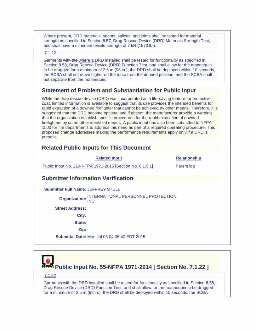
Where present, DRD materials, seams, splices, and joints shall be tested for material strength as specified in Section 8.57, Drag Rescue Device (DRD) Materials Strength Test, and shall have a minimum tensile strength of 7 kN (1573 lbf).
7.1.22
Garments with the where a DRD installed shall be tested for functionality as specified in Section 8.58, Drag Rescue Device (DRD) Function Test, and shall allow for the mannequin to be dragged for a minimum of 2.5 m (98 in.), the DRD shall be deployed within 10 seconds, the SCBA shall not move higher on the torso from the donned position, and the SCBA shall not separate from the mannequin.
Statement of Problem and Substantiation for Public Input
While the drag rescue device (DRD) was incorporated as a life-saving feature for protective coat, limited information is available to suggest that its use provides the intended benefits for rapid extraction of a downed firefighter that cannot be achieved by other means. Therefore, it is suggested that the DRD become optional and if absent, the manufacturer provide a warning that the organization establish specific procedures for the rapid extrication of downed firefighters by some other identified means. A public input has also been submitted to NFPA 1500 for fire departments to address this need as part of a required operating procedure. This proposed change addresses making the performance requirements apply only if a DRD is present.
Related Public Inputs for This Document
Related Input Relationship
Public Input No. 219-NFPA 1971-2015 [Section No. 6.1.9.1] Parent log
Submitter Information Verification
Submitter Full Name: JEFFREY STULL
Organization: INTERNATIONAL PERSONNEL PROTECTION, INC.
Street Address:
City:
State:
Zip:
Submittal Date: Mon Jul 06 04:36:40 EDT 2015
Public Input No. 55-NFPA 1971-2014 [ Section No. 7.1.22 ]
7.1.22
Garments with the DRD installed shall be tested for functionality as specified in Section 8.58, Drag Rescue Device (DRD) Function Test, and shall allow for the mannequin to be dragged for a minimum of 2.5 m (98 in.), the DRD shall be deployed within 10 seconds, the SCBA
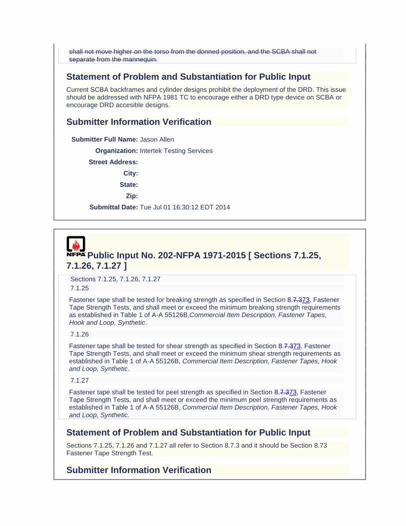
shall not move higher on the torso from the donned position, and the SCBA shall not separate from the mannequin.
Statement of Problem and Substantiation for Public Input
Current SCBA backframes and cylinder designs prohibit the deployment of the DRD. This issue should be addressed with NFPA 1981 TC to encourage either a DRD type device on SCBA or encourage DRD accesible designs.
Submitter Information Verification
Submitter Full Name: Jason Allen
Organization: Intertek Testing Services
Street Address:
City:
State:
Zip:
Submittal Date: Tue Jul 01 16:30:12 EDT 2014
Public Input No. 202-NFPA 1971-2015 [ Sections 7.1.25, 7.1.26, 7.1.27 ]
Sections 7.1.25, 7.1.26, 7.1.27
7.1.25
Fastener tape shall be tested for breaking strength as specified in Section 8.7.373, Fastener Tape Strength Tests, and shall meet or exceed the minimum breaking strength requirements as established in Table 1 of A-A 55126B,Commercial Item Description, Fastener Tapes, Hook and Loop, Synthetic.
7.1.26
Fastener tape shall be tested for shear strength as specified in Section 8.7.373, Fastener Tape Strength Tests, and shall meet or exceed the minimum shear strength requirements as established in Table 1 of A-A 55126B, Commercial Item Description, Fastener Tapes, Hook and Loop, Synthetic.
7.1.27
Fastener tape shall be tested for peel strength as specified in Section 8.7.373, Fastener Tape Strength Tests, and shall meet or exceed the minimum peel strength requirements as established in Table 1 of A-A 55126B, Commercial Item Description, Fastener Tapes, Hook and Loop, Synthetic.
Statement of Problem and Substantiation for Public Input
Sections 7.1.25, 7.1.26 and 7.1.27 all refer to Section 8.7.3 and it should be Section 8.73 Fastener Tape Strength Test.
Submitter Information Verification
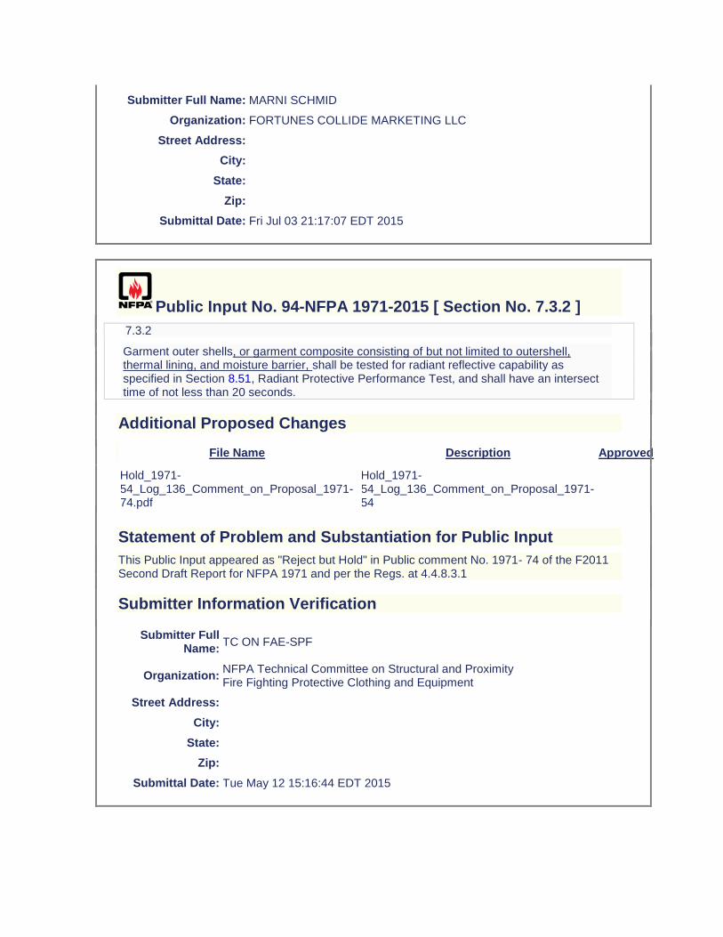
Submitter Full Name: MARNI SCHMID
Organization: FORTUNES COLLIDE MARKETING LLC
Street Address:
City:
State:
Zip:
Submittal Date: Fri Jul 03 21:17:07 EDT 2015
Public Input No. 94-NFPA 1971-2015 [ Section No. 7.3.2 ]
7.3.2
Garment outer shells, or garment composite consisting of but not limited to outershell, thermal lining, and moisture barrier, shall be tested for radiant reflective capability as specified in Section 8.51, Radiant Protective Performance Test, and shall have an intersect time of not less than 20 seconds.
Additional Proposed Changes
File Name Description Approved
Hold_1971-54_Log_136_Comment_on_Proposal_1971-74.pdf
Hold_1971-54_Log_136_Comment_on_Proposal_1971-54
Statement of Problem and Substantiation for Public Input
This Public Input appeared as "Reject but Hold" in Public comment No. 1971- 74 of the F2011 Second Draft Report for NFPA 1971 and per the Regs. at 4.4.8.3.1
Submitter Information Verification
Submitter Full Name:
TC ON FAE-SPF
Organization: NFPA Technical Committee on Structural and Proximity Fire Fighting Protective Clothing and Equipment
Street Address:
City:
State:
Zip:
Submittal Date: Tue May 12 15:16:44 EDT 2015
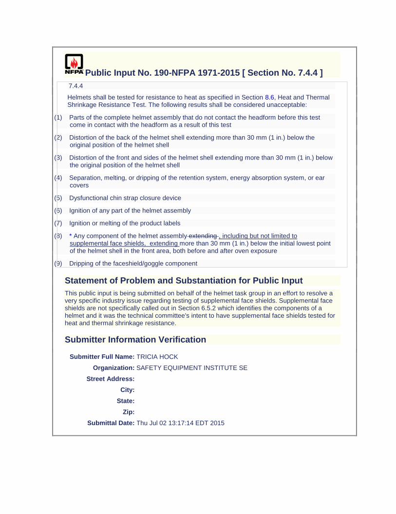
Public Input No. 190-NFPA 1971-2015 [ Section No. 7.4.4 ]
7.4.4
Helmets shall be tested for resistance to heat as specified in Section 8.6, Heat and Thermal Shrinkage Resistance Test. The following results shall be considered unacceptable:
(1) Parts of the complete helmet assembly that do not contact the headform before this test come in contact with the headform as a result of this test
(2) Distortion of the back of the helmet shell extending more than 30 mm (1 in.) below the original position of the helmet shell
(3) Distortion of the front and sides of the helmet shell extending more than 30 mm (1 in.) below the original position of the helmet shell
(4) Separation, melting, or dripping of the retention system, energy absorption system, or ear covers
(5) Dysfunctional chin strap closure device
(6) Ignition of any part of the helmet assembly
(7) Ignition or melting of the product labels
(8) * Any component of the helmet assembly extending , including but not limited to supplemental face shields, extending more than 30 mm (1 in.) below the initial lowest point of the helmet shell in the front area, both before and after oven exposure
(9) Dripping of the faceshield/goggle component
Statement of Problem and Substantiation for Public Input
This public input is being submitted on behalf of the helmet task group in an effort to resolve a very specific industry issue regarding testing of supplemental face shields. Supplemental face shields are not specifically called out in Section 6.5.2 which identifies the components of a helmet and it was the technical committee's intent to have supplemental face shields tested for heat and thermal shrinkage resistance.
Submitter Information Verification
Submitter Full Name: TRICIA HOCK
Organization: SAFETY EQUIPMENT INSTITUTE SE
Street Address:
City:
State:
Zip:
Submittal Date: Thu Jul 02 13:17:14 EDT 2015
Public Input No. 104-NFPA 1971-2015 [ Section No. 7.4.7 ]
7.4.7
Helmets shall be tested for retention ability as specified in Section 8.34, Retention System Test, without any break occurring and without any resulting slip or stretch of no less than 1.5 inches (38.1mm) nor more than 20 mm ( 13⁄16 in.2 inches (50.8mm).
Additional Proposed Changes
File Name Description Approved
Firemen_NFPA_Application3.doc
This document includes language revisions, intro comments, drawings, specifications, firefighters familiar with the chinstrap, and reference of similar firefighter injuries.
Statement of Problem and Substantiation for Public Input
Need for a ‘Stretchable’ Chinstrap Eric Lepore is a Western Pennsylvania volunteer firefighter who was injured in a house fire when debris fell on the rear brim of his N5A New Yorker MSA helmet violently pivoting his head backward causing neck and shoulder injuries. Eric suffered two dislocated shoulders, neck and shoulder trauma, was pulled from under fallen debris by fellow firefighters, and was off work for 7 weeks receiving extensive medical treatment. ► Because of 7.4.7 of the 1971 NFPA regulation, a chinstrap tightly secures the helmet to a firefighter’s head whereby impact forces on the helmet brim may be transferred to neck and shoulder muscles. ► To reduce the possibility of this type of injury, the proposed changes in 7.4.7 , 7.4.10 and 7.4.11 of 1971 NFPA regulations would provide that an elastic strip would move within a fire resistant cover or sleeve to partially dissipate and absorb impact forces on helmets. ► Eric is not alone. Approximately 26% of firefighter injuries are head and shoulder related that may be partially addressed with a stretchable chinstrap. http://www.usfa.fema.gov/downloads/pdf/statistics/v11i7.pdf ► Testing was problematic because labs were limited to the elongation limits of the NFPA 1971 regulations and couldn’t evaluate the physiological challenges of bodily injuries to a helmet off center ball drop test. Regardless of this request, a review of the ball drop test may be in order to evaluate off center impact forces on a helmet brim and other areas of the helmet to simulate actual fire conditions. ► The referenced chinstrap is conceptual at this point in development with suggestions and improvements to the design and materials welcomed by the NFPA Committee membership. ► Considering all the improvements in safety for firefighters especially after September 11, 2001, a review of the 43 year old 1971 regulation may be in order to permit elongation of firefighter chinstraps.
Submitter Information Verification
Submitter Full Name: Joe Lastik
Organization: [ Not Specified ]
Street Address:
City:
State:
Zip:
Submittal Date: Wed Jun 03 11:48:42 EDT 2015
Public Input No. 105-NFPA 1971-2015 [ Section No. 7.4.10 ]
7.4.10
All materials utilized in the construction of helmet chin straps, excluding elastic and hook and pile fasteners where these items are placed so that they will not directly contact the wearer's body or hood or such material is covered with or within fire resistant material, shall be individually tested for resistance to flame as specified in Section 8.2, Flame Resistance Test 1, and shall not have a char length greater than 100 mm (4 in.), shall not show any visible afterflame 2.0 seconds after removal from the test flame, and shall not melt or drip.
Additional Proposed Changes
File Name Description Approved
Firemen_NFPA_Application3.doc
This document includes language revisions, intro comments, drawing, specifications, firefighters familiar with the chinstrap, and reference of similar firefighter injuries.
Statement of Problem and Substantiation for Public Input
Need for a ‘Stretchable’ Chinstrap Eric Lepore is a Western Pennsylvania volunteer firefighter who was injured in a house fire when debris fell on the rear brim of his N5A New Yorker MSA helmet violently pivoting his head backward causing neck and shoulder injuries. Eric suffered two dislocated shoulders, neck and shoulder trauma, was pulled from under fallen debris by fellow firefighters, and was off work for 7 weeks receiving extensive medical treatment. ► Because of 7.4.7 of the 1971 NFPA regulation, a chinstrap tightly secures the helmet to a firefighter’s head whereby impact forces on the helmet brim may be transferred to neck and shoulder muscles. ► To reduce the possibility of this type of injury, the proposed changes in 7.4.7 , 7.4.10 and 7.4.11 of 1971 NFPA regulations would provide that an elastic strip would move within a fire resistant cover or sleeve to partially dissipate and absorb impact forces on helmets. ► Eric is not alone. Approximately 26% of firefighter injuries are head and shoulder related that may be partially addressed with a stretchable chinstrap. http://www.usfa.fema.gov/downloads/pdf/statistics/v11i7.pdf ► Testing was problematic because labs were limited to the elongation limits of the NFPA 1971 regulations and couldn’t evaluate the physiological challenges of bodily injuries to a helmet off center ball drop test. Regardless of this request, a review of the ball drop test may be in order to evaluate off center impact forces on a helmet brim and other areas of the helmet to simulate actual fire conditions. ► The referenced chinstrap is conceptual at this point in development with suggestions and improvements to the design and materials welcomed by the NFPA Committee membership. ► Considering all the improvements in safety for firefighters especially after September 11, 2001, a review of the 43 year old 1971 regulation may be in order to permit elongation of firefighter chinstraps.
Submitter Information Verification
Submitter Full Name: Joe Lastik
Organization: [ Not Specified ]
Street Address:
City:
State:
Zip:
Submittal Date: Wed Jun 03 11:54:09 EDT 2015
Public Input No. 106-NFPA 1971-2015 [ Section No. 7.4.11 ]
7.4.11
All materials utilized in the construction of helmet chin straps, excluding elastic and hook and pile fasteners where these items are placed so that they will not directly contact the wearer's body or hood or such material is covered with or within fire resistant material, shall be individually tested for resistance to heat as specified in Section 8.6, Heat and Thermal Shrinkage Resistance Test, and shall not shrink more than 10 percent in any direction, and shall not melt, separate, or ignite. Helmet chin strap material shall meet the thermal shrinkage requirement for the length dimension only.
Additional Proposed Changes
File Name Description Approved
Firemen_NFPA_Application3.doc
This document includes language revisions, intro comments, drawing, specifications, firefighters familiar with the chinstrap, and reference of similar firefighter injuries.
Statement of Problem and Substantiation for Public Input
Need for a ‘Stretchable’ Chinstrap Eric Lepore is a Western Pennsylvania volunteer firefighter who was injured in a house fire when debris fell on the rear brim of his N5A New Yorker MSA helmet violently pivoting his head backward causing neck and shoulder injuries. Eric suffered two dislocated shoulders, neck and shoulder trauma, was pulled from under fallen debris by fellow firefighters, and was off work for 7 weeks receiving extensive medical treatment. ► Because of 7.4.7 of the 1971 NFPA regulation, a chinstrap tightly secures the helmet to a firefighter’s head whereby impact forces on the helmet brim may be transferred to neck and shoulder muscles. ► To reduce the possibility of this type of injury, the proposed changes in 7.4.7 , 7.4.10 and 7.4.11 of 1971 NFPA regulations would provide that an elastic strip would move within a fire resistant cover or sleeve to partially dissipate and absorb impact forces on helmets. ► Eric is not alone. Approximately 26% of firefighter injuries are head and shoulder related that may be partially addressed with a stretchable chinstrap. http://www.usfa.fema.gov/downloads/pdf/statistics/v11i7.pdf ► Testing was problematic because labs were limited to the elongation limits of the NFPA 1971 regulations and couldn’t evaluate the physiological challenges of bodily injuries to a helmet off center ball drop test. Regardless of this request, a review of the ball drop test may be in order to evaluate off center impact forces on a helmet brim and other areas of the helmet to simulate actual fire conditions.
► The referenced chinstrap is conceptual at this point in development with suggestions and improvements to the design and materials welcomed by the NFPA Committee membership. ► Considering all the improvements in safety for firefighters especially after September 11, 2001, a review of the 43 year old 1971 regulation may be in order to permit elongation of firefighter chinstraps.
Submitter Information Verification
Submitter Full Name: Joe Lastik
Organization: [ Not Specified ]
Street Address:
City:
State:
Zip:
Submittal Date: Wed Jun 03 11:57:15 EDT 2015
Public Input No. 87-NFPA 1971-2015 [ Section No. 7.5.8 ]
7.5.8
All materials utilized in the construction of helmet ear covers, excluding elastic and hook and pile fasteners where these items are placed so that they will not directly contact the wearer's body or hood, shall be individually tested for resistance to heat as specified in Section 8.6, Heat and Thermal Shrinkage Resistance Test, and shall not shrink more than 10 percent in any direction, and shall not melt, separate, or ignite. Helmet chin strap material shall meet the thermal shrinkage requirement for the length dimension only.
Statement of Problem and Substantiation for Public Input
The statement at the end of this requirement was in ROP 1971-77, however, this was a copy and paste error. This requirement deals with ear covers only, not chin strap materials. Chin strap materials are covered for Heat Resistance in 7.4.11 where this statement correctly appears.
Related Public Inputs for This Document
Related Input Relationship
Public Input No. 88-NFPA 1971-2015 [Section No. 7.6.8]
Submitter Information Verification
Submitter Full Name: Michael McKenna
Organization: Michael McKenna & Associates,
Street Address:
City:
State:
Zip:
Submittal Date: Mon Apr 06 14:54:23 EDT 2015
Public Input No. 88-NFPA 1971-2015 [ Section No. 7.6.8 ]
7.6.8
All materials utilized in the construction of proximity helmet covers and shrouds, excluding elastic and hook and pile fasteners where these items are placed so that they will not directly contact the wearer's body or hood, shall be individually tested for resistance to heat as specified in Section 8.6, Heat and Thermal Shrinkage Resistance Test, and shall not shrink more than 10 percent in any direction, and shall not melt, separate, or ignite. Helmet chin strap material shall meet the thermal shrinkage requirement for the length dimension only.
Statement of Problem and Substantiation for Public Input
The statement at the end of this requirement was in ROP 1971-77, however, this was a copy and paste error. This requirement deals with ear covers only, not chin strap materials. Chin strap materials are covered for Heat Resistance in 7.4.11 where this statement correctly appears.
Related Public Inputs for This Document
Related Input Relationship
Public Input No. 87-NFPA 1971-2015 [Section No. 7.5.8]
Submitter Information Verification
Submitter Full Name: Michael McKenna
Organization: Michael McKenna & Associates,
Street Address:
City:
State:
Zip:
Submittal Date: Mon Apr 06 14:56:14 EDT 2015
Public Input No. 144-NFPA 1971-2015 [ New Section after 7.7 ]
7.6.19 Proximity face shields shall be tested for adhesion of reflective coating
as specified in Section 8XX, Adhesion of Reflective Coating on Proximity Face Shield - Tape Method, and shall show no evidence of the coating on the tape.
Statement of Problem and Substantiation for Public Input
Substantiation - The standard doesn't have any durability testing of the coating and during fire operations when you try to clear your face shield you can wipe the coating off.
Related Public Inputs for This Document
Related Input Relationship
Public Input No. 143-NFPA 1971-2015 [New Section after 8.45]
Submitter Information Verification
Submitter Full Name: HARRY WINER
Organization: HIP CONSULTING LLC
Street Address:
City:
State:
Zip:
Submittal Date: Mon Jun 29 09:33:17 EDT 2015
Public Input No. 145-NFPA 1971-2015 [ New Section after 7.7 ]
7.6.20 Proximity face shields shall be tested for abrasion of reflective coating
as specified in Section 8.XX, Abrasion of Reflective Coating on Proximity Face Shield and shall show no evidence of the hazing, marks or scratching on the reflective coating.
Statement of Problem and Substantiation for Public Input
Substantiation - The standard doesn't have any durability testing of the coating and during fire operations when you try to clear your face shield you can wipe the coating off.
Related Public Inputs for This Document
Related Input Relationship
Public Input No. 142-NFPA 1971-2015 [New Section after 8.45]
Submitter Information Verification
Submitter Full Name: HARRY WINER
Organization: HIP CONSULTING LLC
Street Address:
City:
State:
Zip:
Submittal Date: Mon Jun 29 09:36:23 EDT 2015
Public Input No. 233-NFPA 1971-2015 [ New Section after 7.7 ]
TITLE OF NEW CONTENT
7.7.X (NEW)
Portions of the glove body composite representative of the back of the glove shall be tested for radiant heat resistance as specified in Section 8.X, Radiant Heat Resistance Test 4, and shall have a second-degree burn time of not less than 90.0 seconds.
Statement of Problem and Substantiation for Public Input
A new test has been proposed to measuring the thermal insulation for the back of the gloves that is more consistent with the type of exposure that generally occurs for this portion of the gloves (radiant heat) as opposed to conductive heat resistance. The new test is based on use of the same radiant panel used for self-contained breathing apparatus facepieces and utilized a new wetting technique that provides a uniform mist exposure of the thermal barrier (innermost) layer of the glove composite to serve as a worse case wetting condition. The specimen holder, sensor, and data acquisition/data analysis system are similar to the equipment specified in ASTM F1939 (RPP test). The test provided output as the time to a predicted second degree burn injury and an initial performance criterion of greater than 90 seconds has been proposed. The test method and sample conditioning technique are undergoing further validation and a limited interlaboratory test program is proposed over the fall of 2015 and early spring of 2016. This proposal provideS the recommended new performance criterion.
Related Public Inputs for This Document
Related Input Relationship
Public Input No. 231-NFPA 1971-2015 [Section No. 7.7.4] Parent log
Submitter Information Verification
Submitter Full Name: JEFFREY STULL
Organization: INTERNATIONAL PERSONNEL PROTECTION, INC.
Street Address:
City:
State:
Zip:
Submittal Date: Mon Jul 06 13:33:24 EDT 2015
Public Input No. 244-NFPA 1971-2015 [ New Section after 7.7.2.1 ]
TITLE OF NEW CONTENT
Type your content here ...PTFE handform shall be able to be removed within 3 /-0.5 minutes following the 260C for 5 min Heat exposure with less than 100N of force
Statement of Problem and Substantiation for Public Input
A test is needed to quantify the don/doffing ability of gloves post heat test
Submitter Information Verification
Submitter Full Name: JASON ALLEN
Organization: INTERTEK TESTING SERVICES
Street Address:
City:
State:
Zip:
Submittal Date: Mon Jul 06 14:27:16 EDT 2015
Public Input No. 231-NFPA 1971-2015 [ Section No. 7.7.4 ]
7.7.4
The Portions of the glove body composite representative of the palm of the glove shall be tested for thermal insulation conductive heat resistance as specified in Section 8.7, Conductive Heat Resistance Test 1, and shall have a second-degree burn time of not less than 10.0 seconds, and shall have a pain time of not less than 6.0 seconds.
Statement of Problem and Substantiation for Public Input
A new test has been proposed to measuring the thermal insulation for the back of the gloves that is more consistent with the type of exposure that generally occurs for this portion of the gloves (radiant heat) as opposed to conductive heat resistance. The new test is based on use of the same radiant panel used for self-contained breathing apparatus facepieces and utilized a new wetting technique that provides a uniform mist exposure of the thermal barrier (innermost)
layer of the glove composite to serve as a worse case wetting condition. The specimen holder, sensor, and data acquisition/data analysis system are similar to the equipment specified in ASTM F1939 (RPP test). The test provided output as the time to a predicted second degree burn injury and an initial performance criterion of greater than 90 seconds has been proposed. The test method and sample conditioning technique are undergoing further validation and a limited interlaboratory test program is proposed over the fall of 2015 and early spring of 2016. The specific change indicated with this input is to limit the current conductive heat resistance test to the palm side of the gloves.
Related Public Inputs for This Document
Related Input Relationship
Public Input No. 233-NFPA 1971-2015 [New Section after 7.7]
Public Input No. 234-NFPA 1971-2015 [New Section after 8.1]
Public Input No. 235-NFPA 1971-2015 [Section No. 8.7]
Public Input No. 236-NFPA 1971-2015 [New Section after 8.74]
Submitter Information Verification
Submitter Full Name: JEFFREY STULL
Organization: INTERNATIONAL PERSONNEL PROTECTION, INC.
Street Address:
City:
State:
Zip:
Submittal Date: Mon Jul 06 13:25:12 EDT 2015
Public Input No. 6-NFPA 1971-2013 [ Sections 7.7.7, 7.7.8 ]
Sections 7.7.7, 7.7.8
7.7.7
The glove extension interface composite, including, but not limited to, trim, external labels, and external tags, but excluding hardware and hook and pile fasteners that do not directly contact the wearer's body, shall be tested for resistance to flame as specified in Section 8.4, Flame Resistance Test 3, and shall not have an average char length of more than 100 mm (4 in.), shall not have an average afterflame of more than 2.0 seconds, shall not melt or drip, and shall not have the amount of consumed materials exceed 5 percent.
7.7.8*
All sewing thread utilized in the construction of gloves The glove extension composite, including, but not limited to, trim, external labels, and external tags, but excluding hardware and hook and pile fasteners that do not directly contact the wearer's body, shall be tested for
melting
resistance to flame as specified in Section 8.
11
4,
Thread Melting
Flame Resistance Test 3, and shall not
melt at or below 260°C (500°F).
have an average char length of more than 100 mm (4 in.), shall not have an average afterflame of more than 2.0 seconds, shall not melt or drip, and shall not have the amount of consumed materials exceed 5 percent.
Additional Proposed Changes
File Name Description Approved
Proposed_TIA_1092_1971_.docx Balloted TIA
Statement of Problem and Substantiation for Public Input
Note: This Public Input originates from Tentative Interim Amendment 1971-13-2 (TIA 1092) issued by the Standards Council on March 7, 2013. 1. The ASTM 2412 Standard needs to be updated to the current edition. 2, 3, and 14. The specific requirements for glove labels, which included type of fiber or material type, were inadvertently included in the generic list of requirements for labels on all ensemble elements. Since the majority of fabrics and materials used in construction of many of the ensemble elements contain multiple fibers and numerous blends, even attempting to include this level of detail on every product label would cause mass confusion. The issue becomes even more exacerbated by the minimum font sizes required on label text and by a garment specific label requirement, also included in the generic list, which mandates explicit component names as per the certification listing. This change provides the generic requirements for all labels, and then separates the specific ensemble element label requirements into subsets to avoid any interpretation issues. 4. The NFPA 1971 proposal (1971-46, Log CP-50) neglected to include the test method reference to Section 8.4 as well as the requirement for char length. NFPA 1971, 2013 edition references several flame resistance tests. It is important the standard references the correct flame resistance test and section number to insure the correct testing procedures are being followed. It was also the technical committee’s intent, based on historical data, to have the glove interface component evaluated for char length in addition to afterflame. 5. The NFPA 1971 proposal (1971-46, Log CP-50) neglected to include the test method reference to Section 8.4 as well as the requirement for char length. NFPA 1971, 2013 edition references several flame resistance tests. It is important the standard references the correct flame resistance test and section number to insure the correct testing procedures are being followed. It was also the technical committee’s intent, based on historical data, to have the glove extension component evaluated for char length in addition to afterflame. 6. This change brings this requirement in line with EN ISO 20345:2011. 7. The current laundering method described in Section 8.1.11 only accounts for water levels when laundering garments and CBRN Materials. The 2013 edition of NFPA 1971 now requires gloves and glove pouches to be laundered using Section 8.1.11 as a precondition. However a table for gloves and glove pouch water levels were not included. The water levels for the glove and glove pouch wash cycle needs to be specified in NFPA 1971, 2013 edition in order to allow for the front load wash machines to be properly programmed at the testing laboratories. The highest water levels currently in the standard were chosen to account for usage of both 35 lb and 50 lb capacity front-loading machines. The higher levels will also accommodate a full load
of gloves/glove pouches and eliminate any risk associated with residual detergent. 8, 9, 15 and 16. Some changes made to the way the measurement of hood shrinkage were specified in cleaning shrinkage as part of the NFPA 1971-2013 revision would prevent any hood from being certified to the new requirements. There was also an inconsistency between how hood shrinkage was evaluated for both thermal and cleaning shrinkage for the interpretation of test results that would lead to inconsistent determinations of compliance among testing laboratories. The proposed changes using the same approach established in the 2007 edition of NFPA 1971 for applying cleaning shrinkage criteria while clarifications have been made for interpretation of permitted shrinkage in both cleaning and thermal shrinkage test methods. 10. NFPA 1971, 2013 edition has sections for glove pouch construction, sections 8.1.15 and 8.1.16. Section 8.27.8.2, section for Liquid Penetration Resistance, should reference section 8.1.16 for moisture barrier testing. 11. NFPA 1971, 2013 edition has sections for glove pouch construction, sections 8.1.15 and 8.1.16. Section 8.28.8.2, section for Viral Penetration Resistance, should reference section 8.1.16 for moisture barrier testing. 12. The ISO 13287 standard does not provide criteria for the evaluation of systematic increase or decrease of values. Also, the current calibration language is not clear. 13. The test apparatus will be maxed out if the test subject uses their arm’s range of motion to perform this test. In order to achieve more accurate results it is important the test subject use their wrist’s range of motion to perform this test. Emergency Nature: This TIA seeks to correct errors and omissions that were overlooked during the Fall 2013 revision cycle process of NFPA 1971. Additionally, some parts of this TIA correct circumstances in which the standard could adversely impact a method or product that was inadvertently overlooked in the total revision process.
Submitter Information Verification
Submitter Full Name: TC on FAE-SPF
Organization: NFPA
Street Address:
City:
State:
Zip:
Submittal Date: Fri Aug 09 14:12:22 EDT 2013
Public Input No. 204-NFPA 1971-2015 [ Section No. 7.7.15 ]
7.7.15
Knit glove wristlet material(s) shall be tested for material strength as specified in Section 8.13, Burst Strength Test, and shall have a burst strength of not less than 225 N (50 51 lbf).
Statement of Problem and Substantiation for Public Input
The Education Task Group discovered a discrepancy in the conversion of the 225 N requirement. A value of 51 lbs is the closer equivalent value and consistent with the analogous requirement in 7.13.8.
Submitter Information Verification
Submitter Full Name: JEFFREY STULL
Organization: INTERNATIONAL PERSONNEL PROTECTION, INC.
Street Address:
City:
State:
Zip:
Submittal Date: Sat Jul 04 12:48:46 EDT 2015
Public Input No. 28-NFPA 1971-2013 [ Section No. 7.7.21 ]
7.7.21
Gloves shall be tested for grip as specified in Section 8.38, Grip Test, and shall not have a percentage drop of barehanded control value of not less than 90.force of more than 30 percent in any 0.2 second interval.
Additional Proposed Changes
File Name Description Approved
Proposed_TIA_1100_1971_.docx Balloted TIA
Statement of Problem and Substantiation for Public Input
Note: This Public Input originates from Tentative Interim Amendment 1971-13-3 (TIA 1100) issued by the Standards Council on August 1, 2013. As currently written, more information is needed to fully explain how the pulls are to be performed, and also how the graphic results are to be interpreted. This is necessary to ensure consistent testing is performed. The test method as currently written does not provide sufficient detail in order for the test to be consistently applied in the evaluation of glove grip and requires interpretation of the testing laboratory to determine the appropriate body and hand position, which have a significant impact on the test results. Specific changes have been proposed in the position of the test subject’s body and hands that alter the original instructions for performing the test. The additional details are intended to ensure that laboratories performing this test conduct the test in exactly the same way. Photographs of the proper positioning of the test subject body and hands with respect to the pole are included in the proposed modifications to provide a clear interpretation for running this part of the test. In addition, it is proposed to base the performance of glove grip on a change in the measured force relative to the time interval in which that change occurs. Consequently, the criteria in paragraph 7.7.22 have been modified. This modification was necessary because the degree of test subject hand slipping on the pole can occur at varying rates (force over time) leading to widely different application of the test results and potential failure of gloves that are considered to have acceptable performance. These changes were developed as the result of a meeting between Intertek Testing Services, the North Carolina State University Textile Protection and Comfort Center, and Underwriters’ Laboratories, where these organizations worked together to determine how to consistently run the test method and achieve better precision in test results. The involvement of these organizations and their work on this test method were pursuant to a recommendation made by the Technical Committee on

Structural and Proximity Fire Fighting Protective Clothing during a committee teleconference held December 2012 where specific problems with the test method and its application in NFPA 1971 were identified. Emergency Nature: The document contains an error or an omission that was overlooked during a regular revision process. After interlaboratory coordination it was determined that the additional language is necessary to perform consistent testing and to ensure a consistent level of compliant product available to users.
Submitter Information Verification
Submitter Full Name:
TC on FAE-SPF
Organization: TC on Structural and Proximity Fire Fighting Protective Clothing and Equipment
Street Address:
City:
State:
Zip:
Submittal Date: Fri Sep 06 13:41:07 EDT 2013
Public Input No. 7-NFPA 1971-2013 [ Section No. 7.10.9 ]
7.10.9
Footwear soles and heels shall be tested for resistance to abrasion as specified in Section 8.2423, Abrasion Resistance Test, and the relative volume loss shall not be greater than 200 250 mm3.
Additional Proposed Changes
File Name Description Approved
Proposed_TIA_1092_1971_.docx Balloted TIA
Statement of Problem and Substantiation for Public Input
Note: This Public Input originates from Tentative Interim Amendment 1971-13-2 (TIA 1092) issued by the Standards Council on March 7, 2013. 1. The ASTM 2412 Standard needs to be updated to the current edition. 2, 3, and 14. The specific requirements for glove labels, which included type of fiber or material type, were inadvertently included in the generic list of requirements for labels on all ensemble elements. Since the majority of fabrics and materials used in construction of many of the ensemble elements contain multiple fibers and numerous blends, even attempting to include this level of detail on every product label would cause mass confusion. The issue becomes even more exacerbated by the minimum font sizes required on label text and by a garment specific label requirement, also included in the generic list, which mandates explicit component names as per the certification listing. This change provides the generic requirements for all labels, and then separates the specific ensemble element label requirements into subsets to avoid any interpretation issues. 4. The NFPA 1971 proposal (1971-46, Log CP-50) neglected to include the test method reference to Section 8.4 as well as the requirement for char length. NFPA 1971, 2013 edition references several flame resistance
tests. It is important the standard references the correct flame resistance test and section number to insure the correct testing procedures are being followed. It was also the technical committee’s intent, based on historical data, to have the glove interface component evaluated for char length in addition to afterflame. 5. The NFPA 1971 proposal (1971-46, Log CP-50) neglected to include the test method reference to Section 8.4 as well as the requirement for char length. NFPA 1971, 2013 edition references several flame resistance tests. It is important the standard references the correct flame resistance test and section number to insure the correct testing procedures are being followed. It was also the technical committee’s intent, based on historical data, to have the glove extension component evaluated for char length in addition to afterflame. 6. This change brings this requirement in line with EN ISO 20345:2011. 7. The current laundering method described in Section 8.1.11 only accounts for water levels when laundering garments and CBRN Materials. The 2013 edition of NFPA 1971 now requires gloves and glove pouches to be laundered using Section 8.1.11 as a precondition. However a table for gloves and glove pouch water levels were not included. The water levels for the glove and glove pouch wash cycle needs to be specified in NFPA 1971, 2013 edition in order to allow for the front load wash machines to be properly programmed at the testing laboratories. The highest water levels currently in the standard were chosen to account for usage of both 35 lb and 50 lb capacity front-loading machines. The higher levels will also accommodate a full load of gloves/glove pouches and eliminate any risk associated with residual detergent. 8, 9, 15 and 16. Some changes made to the way the measurement of hood shrinkage were specified in cleaning shrinkage as part of the NFPA 1971-2013 revision would prevent any hood from being certified to the new requirements. There was also an inconsistency between how hood shrinkage was evaluated for both thermal and cleaning shrinkage for the interpretation of test results that would lead to inconsistent determinations of compliance among testing laboratories. The proposed changes using the same approach established in the 2007 edition of NFPA 1971 for applying cleaning shrinkage criteria while clarifications have been made for interpretation of permitted shrinkage in both cleaning and thermal shrinkage test methods. 10. NFPA 1971, 2013 edition has sections for glove pouch construction, sections 8.1.15 and 8.1.16. Section 8.27.8.2, section for Liquid Penetration Resistance, should reference section 8.1.16 for moisture barrier testing. 11. NFPA 1971, 2013 edition has sections for glove pouch construction, sections 8.1.15 and 8.1.16. Section 8.28.8.2, section for Viral Penetration Resistance, should reference section 8.1.16 for moisture barrier testing. 12. The ISO 13287 standard does not provide criteria for the evaluation of systematic increase or decrease of values. Also, the current calibration language is not clear. 13. The test apparatus will be maxed out if the test subject uses their arm’s range of motion to perform this test. In order to achieve more accurate results it is important the test subject use their wrist’s range of motion to perform this test. Emergency Nature: This TIA seeks to correct errors and omissions that were overlooked during the Fall 2013 revision cycle process of NFPA 1971. Additionally, some parts of this TIA correct circumstances in which the standard could adversely impact a method or product that was inadvertently overlooked in the total revision process.
Submitter Information Verification
Submitter Full Name:
TC on FAE-SPF
Organization: TC on Structural and Proximity Fire Fighting Protective Clothing and Equipment
Street Address:
City:
State:
Zip:
Submittal Date: Fri Aug 09 14:16:06 EDT 2013
Public Input No. 158-NFPA 1971-2015 [ Section No. 7.10.13 ]
7.10.13
All footwear metal hardware and specimens of all footwear hardware that include metal parts, including, but not limited to, toe cap, ladder shank, puncture-resistant device, and components shall be individually tested for resistance to corrosion as specified in Section 8.29, Corrosion Resistance Test, and shall have metals that are inherently resistant to corrosion including but not limited to stainless steel, brass, copper, aluminum, and zinc show no more than light surface-type corrosion or oxidation, shall have ferrous metals show no corrosion of the base metal, and shall have all hardware remain functional.
Statement of Problem and Substantiation for Public Input
Editorial. This is a clarification because corrosion resistance of the puncture resistant device is now addressed by ASTM F2413 (see 6.10.9). ASTM F2413's corrosion test is the same as NFPA 1971 except 24 hour exposure instead of 20 hour exposure making ASTM F2413 more severe.
Submitter Information Verification
Submitter Full Name: ROBIN TUTOR
Organization: UL LLC
Street Address:
City:
State:
Zip:
Submittal Date: Mon Jun 29 14:38:19 EDT 2015
Public Input No. 261-NFPA 1971-2015 [ New Section after 7.13 ]
THL for Hood Materials
Hood composites or materials shall be tested for evaporative heat transfer as specified in Section 8.33, Total Heat Loss (THL) Test, and
shall have a THL of not less than 205 W/m 2 .
Statement of Problem and Substantiation for Public Input
Hoods are being produced today that have a great deal more protection than the typical knitted thermal hoods. Some of these hoods have a membrane and mimic a typical turnout composite. There is also nothing preventing an impermeable membrane being used in the hood for
increased protection. Considering the amount of heat that can be lost through the head the committee should consider having a THL requirement for hood materials.
Submitter Information Verification
Submitter Full Name: Anthoney Deaton
Organization: NC State University
Street Address:
City:
State:
Zip:
Submittal Date: Mon Jul 06 19:15:46 EDT 2015
Public Input No. 121-NFPA 1971-2015 [ Section No. 7.13.1 [Excluding any Sub-Sections] ]
Fire fighting protective hood face openings that are not designed for interface with a specific SCBA facepiece shall be tested for shape retention as specified in Section 8.46, Hood Opening Size Retention Test, and shall not exceed 110 percent of the original face opening sizeshow any gaps.
Statement of Problem and Substantiation for Public Input
This updates the requirement to match the new procedure for measuring hood face openings based on the task group findings.
Related Public Inputs for This Document
Related Input Relationship
Public Input No. 107-NFPA 1971-2015 [Section No. 6.13.6.1]
Public Input No. 117-NFPA 1971-2015 [Sections 8.46.4.2, 8.46.4.3, 8.46.4.4, 8.46.4.5, 8.46.4.6, ...]
Public Input No. 118-NFPA 1971-2015 [Section No. 8.46.6]
Public Input No. 119-NFPA 1971-2015 [Section No. 8.46.8]
Submitter Information Verification
Submitter Full Name: AMANDA NEWSOM
Organization: UL LLC
Street Address:
City:
State:
Zip:
Submittal Date: Mon Jun 08 15:11:01 EDT 2015
Public Input No. 122-NFPA 1971-2015 [ Section No. 7.13.4 ]
7.13.4
Hoods, excluding labels, hook and pile fasteners, and elastic, shall be individually tested for resistance to heat as specified in Section 8.6, Heat and Thermal Shrinkage Resistance Test, and shall show no evidence of gaps and shall not shrink more than 10 percent.
Statement of Problem and Substantiation for Public Input
This updates the requirement to match the new procedure for measuring hood face openings based on the task group findings.
Related Public Inputs for This Document
Related Input Relationship
Public Input No. 107-NFPA 1971-2015 [Section No. 6.13.6.1]
Public Input No. 120-NFPA 1971-2015 [Section No. 8.6.16]
Submitter Information Verification
Submitter Full Name: AMANDA NEWSOM
Organization: UL LLC
Street Address:
City:
State:
Zip:
Submittal Date: Mon Jun 08 15:13:55 EDT 2015
Public Input No. 123-NFPA 1971-2015 [ Section No. 7.13.6 ]
7.13.6
Hoods shall be individually tested for resistance to shrinkage as specified in Section 8.24, Cleaning Shrinkage Resistance Test, and shall not have the measurements made from the top of the hood to the marks at the back and both sides of the hood exhibit shrinkage of more than 5 percent, and shall have the hood opening meet the requirements specified in 6.13.6.show no evidence of gaps.

Statement of Problem and Substantiation for Public Input
This updates the requirement to match the new procedure for measuring hood face openings based on the task group findings.
Related Public Inputs for This Document
Related Input Relationship
Public Input No. 107-NFPA 1971-2015 [Section No. 6.13.6.1]
Public Input No. 108-NFPA 1971-2015 [Section No. 8.24.9.3]
Public Input No. 109-NFPA 1971-2015 [New Section after 8.24.9.3]
Public Input No. 110-NFPA 1971-2015 [Section No. 8.24.9.5]
Public Input No. 111-NFPA 1971-2015 [Section No. 8.24.9.6]
Public Input No. 112-NFPA 1971-2015 [Section No. 8.24.9.7]
Public Input No. 114-NFPA 1971-2015 [Section No. 8.24.9.10]
Public Input No. 115-NFPA 1971-2015 [Section No. 8.24.9.12]
Public Input No. 116-NFPA 1971-2015 [Section No. 8.24.9.14]
Submitter Information Verification
Submitter Full Name: AMANDA NEWSOM
Organization: UL LLC
Street Address:
City:
State:
Zip:
Submittal Date: Mon Jun 08 15:15:41 EDT 2015
Public Input No. 8-NFPA 1971-2013 [ Section No. 7.13.6 ]
7.13.6
Hoods shall be individually tested for resistance to shrinkage as specified in Section 8.24, Cleaning Shrinkage Resistance Test, and shall not have the measurements made from the top of the hood to the marks at the back and both sides of the hood exhibit shrinkage of more than 5 percent, and shall have the hood opening meet the requirements specified in 6.13.6.
Additional Proposed Changes
File Name Description Approved
Proposed_TIA_1092_1971_.docx Balloted TIA
Statement of Problem and Substantiation for Public Input
Note: This Public Input originates from Tentative Interim Amendment 1971-13-2 (TIA 1092) issued by the Standards Council on March 7, 2013. 1. The ASTM 2412 Standard needs to be updated to the current edition. 2, 3, and 14. The specific requirements for glove labels, which included type of fiber or material type, were inadvertently included in the generic list of requirements for labels on all ensemble elements. Since the majority of fabrics and materials used in construction of many of the ensemble elements contain multiple fibers and numerous blends, even attempting to include this level of detail on every product label would cause mass confusion. The issue becomes even more exacerbated by the minimum font sizes required on label text and by a garment specific label requirement, also included in the generic list, which mandates explicit component names as per the certification listing. This change provides the generic requirements for all labels, and then separates the specific ensemble element label requirements into subsets to avoid any interpretation issues. 4. The NFPA 1971 proposal (1971-46, Log CP-50) neglected to include the test method reference to Section 8.4 as well as the requirement for char length. NFPA 1971, 2013 edition references several flame resistance tests. It is important the standard references the correct flame resistance test and section number to insure the correct testing procedures are being followed. It was also the technical committee’s intent, based on historical data, to have the glove interface component evaluated for char length in addition to afterflame. 5. The NFPA 1971 proposal (1971-46, Log CP-50) neglected to include the test method reference to Section 8.4 as well as the requirement for char length. NFPA 1971, 2013 edition references several flame resistance tests. It is important the standard references the correct flame resistance test and section number to insure the correct testing procedures are being followed. It was also the technical committee’s intent, based on historical data, to have the glove extension component evaluated for char length in addition to afterflame. 6. This change brings this requirement in line with EN ISO 20345:2011. 7. The current laundering method described in Section 8.1.11 only accounts for water levels when laundering garments and CBRN Materials. The 2013 edition of NFPA 1971 now requires gloves and glove pouches to be laundered using Section 8.1.11 as a precondition. However a table for gloves and glove pouch water levels were not included. The water levels for the glove and glove pouch wash cycle needs to be specified in NFPA 1971, 2013 edition in order to allow for the front load wash machines to be properly programmed at the testing laboratories. The highest water levels currently in the standard were chosen to account for usage of both 35 lb and 50 lb capacity front-loading machines. The higher levels will also accommodate a full load of gloves/glove pouches and eliminate any risk associated with residual detergent. 8, 9, 15 and 16. Some changes made to the way the measurement of hood shrinkage were specified in cleaning shrinkage as part of the NFPA 1971-2013 revision would prevent any hood from being certified to the new requirements. There was also an inconsistency between how hood shrinkage was evaluated for both thermal and cleaning shrinkage for the interpretation of test results that would lead to inconsistent determinations of compliance among testing laboratories. The proposed changes using the same approach established in the 2007 edition of NFPA 1971 for applying cleaning shrinkage criteria while clarifications have been made for interpretation of permitted shrinkage in both cleaning and thermal shrinkage test methods. 10. NFPA 1971, 2013 edition has sections for glove pouch construction, sections 8.1.15 and 8.1.16. Section 8.27.8.2, section for Liquid Penetration Resistance, should reference section 8.1.16 for moisture barrier testing. 11. NFPA 1971, 2013 edition has sections for glove pouch construction, sections 8.1.15 and 8.1.16. Section 8.28.8.2, section for Viral Penetration Resistance, should reference section 8.1.16 for moisture barrier testing. 12. The ISO 13287 standard does not provide criteria for the evaluation of systematic increase or decrease of values. Also, the current calibration language is not clear. 13. The test apparatus will be maxed out if the test subject uses their arm’s range of motion to perform this test. In order to achieve more accurate results it is important the test subject use their wrist’s range of motion to perform this test. Emergency Nature: This TIA seeks to correct errors and omissions that were overlooked during the Fall 2013 revision cycle process of NFPA 1971. Additionally, some parts
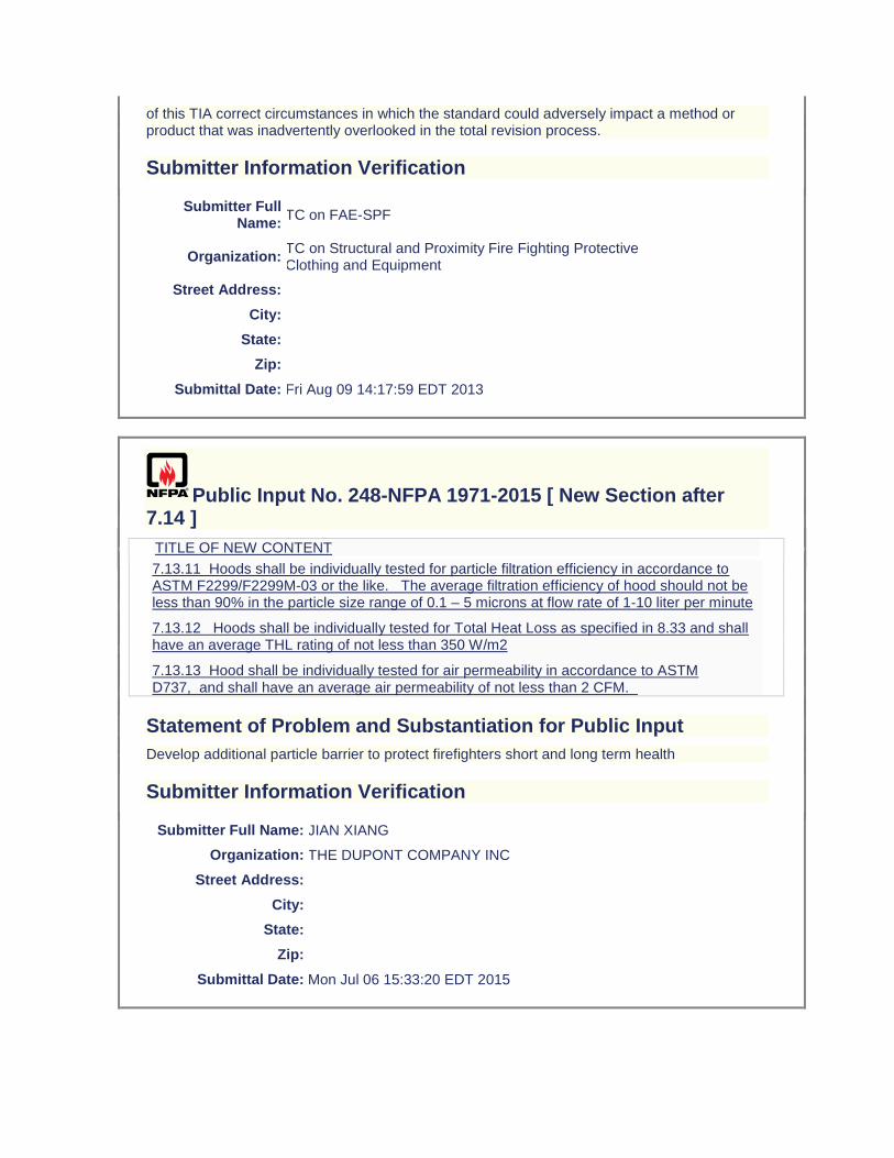
of this TIA correct circumstances in which the standard could adversely impact a method or product that was inadvertently overlooked in the total revision process.
Submitter Information Verification
Submitter Full Name:
TC on FAE-SPF
Organization: TC on Structural and Proximity Fire Fighting Protective Clothing and Equipment
Street Address:
City:
State:
Zip:
Submittal Date: Fri Aug 09 14:17:59 EDT 2013
Public Input No. 248-NFPA 1971-2015 [ New Section after 7.14 ]
TITLE OF NEW CONTENT
7.13.11 Hoods shall be individually tested for particle filtration efficiency in accordance to ASTM F2299/F2299M-03 or the like. The average filtration efficiency of hood should not be less than 90% in the particle size range of 0.1 – 5 microns at flow rate of 1-10 liter per minute
7.13.12 Hoods shall be individually tested for Total Heat Loss as specified in 8.33 and shall have an average THL rating of not less than 350 W/m2
7.13.13 Hood shall be individually tested for air permeability in accordance to ASTM D737, and shall have an average air permeability of not less than 2 CFM.
Statement of Problem and Substantiation for Public Input
Develop additional particle barrier to protect firefighters short and long term health
Submitter Information Verification
Submitter Full Name: JIAN XIANG
Organization: THE DUPONT COMPANY INC
Street Address:
City:
State:
Zip:
Submittal Date: Mon Jul 06 15:33:20 EDT 2015

Public Input No. 247-NFPA 1971-2015 [ Section No. 7.14 ]
7.14 Additional Optional Performance Requirements for Structural Fire Fighting Particulate Barrier Protective Hood Interface Components Only. (Reserved)
7.14.1
Hood barrier materials shall be tested for resistance to particulate penetration as specified in Section 8.X, Particulate Filtration Efficiency Test, and shall have a particulate filtration efficiency of 95% or greater for each particle size from 0.2 μm to 2.0 μm.
7.14.2
Hood barrier materials shall be tested for air permeability as specified in Section 8.Y, Air Permeability Test, and shall have an air permeability of at least 1.7 m 3
/min/m 2 (10 ft 3 /min/ft 2 ).
7.14.3
Hood barrier materials shall be tested for evaporative heat transfer as specified in Section 8.33, Total Heat Loss (THL) Test, and shall have a THL of not less than 300 W/m 2 .
Statement of Problem and Substantiation for Public Input
Protective hoods currently do not require any form of a barrier layer and the majority of protective hoods in the market place are fabricated of two or more layers of an open knit that readily allows smoke and contaminant particles to pass through the hood materials and deposit on the wearer’s skin. Optional requirements for a hood are proposed that define a barrier that limits the passage of particulates as addressed by both design and performance requirements. The proposed changes in this input provide recommended performance requirements for an optional particular barrier hood interface component. A white paper on this topic is attached.
Related Public Inputs for This Document
Related Input Relationship
Public Input No. 246-NFPA 1971-2015 [New Section after 1.1.2] Parent Log
Submitter Information Verification
Submitter Full Name: JEFFREY STULL
Organization: INTERNATIONAL PERSONNEL PROTECTION, INC.
Street Address:
City:
State:
Zip:
Submittal Date: Mon Jul 06 15:24:29 EDT 2015
Public Input No. 234-NFPA 1971-2015 [ New Section after 8.1 ]
TITLE OF NEW CONTENT
8.1.X
Add new section for wet conditioning of glove composites (procedure 2)
Additional Proposed Changes
File Name Description Approved
New_Glove_Composite_Wetting_Procedure_2.docx Proposed new glove composite wet conditioning procedures (2)
Statement of Problem and Substantiation for Public Input
A new test has been proposed to measuring the thermal insulation for the back of the gloves that is more consistent with the type of exposure that generally occurs for this portion of the gloves (radiant heat) as opposed to conductive heat resistance. The new test is based on use of the same radiant panel used for self-contained breathing apparatus facepieces and utilized a new wetting technique that provides a uniform mist exposure of the thermal barrier (innermost) layer of the glove composite to serve as a worse case wetting condition. The specimen holder, sensor, and data acquisition/data analysis system are similar to the equipment specified in ASTM F1939 (RPP test). The test provided output as the time to a predicted second degree burn injury and an initial performance criterion of greater than 90 seconds has been proposed. The test method and sample conditioning technique are undergoing further validation and a limited interlaboratory test program is proposed over the fall of 2015 and early spring of 2016. This proposal provides the recommended new glove composite conditioning procedures.
Related Public Inputs for This Document
Related Input Relationship
Public Input No. 231-NFPA 1971-2015 [Section No. 7.7.4] parent log
Submitter Information Verification
Submitter Full Name: JEFFREY STULL
Organization: INTERNATIONAL PERSONNEL PROTECTION, INC.
Street Address:
City:
State:
Zip:
Submittal Date: Mon Jul 06 13:41:52 EDT 2015

Public Input No. 207-NFPA 1971-2015 [ Section No. 8.1.2 ]
8.1.2 Washing and Drying Procedure for Garments, Gloves, Hoods, and Wristlets.
Specimens 8.1.2.1 Garment, hood, and wristlet specimens shall be subjected to five cycles
of washing and drying in accordance with the procedure specified in Machine Cycle 1, Wash Temperature V, and Drying Procedure Ai of AATCC 135, Dimensional Changes in Automatic Home Laundering of Woven and Knit Fabrics. A 1.82 kg, ± 01 kg (4.0 lb, ± 0.2 b), load shall be used. A laundry bag shall not be used. Gloves shall be
8.1.2.2 Glove specimens shall be subjected to five cycles of washing and drying in accordance with the procedure specified in Machine Cycle 1, Wash Temperature V
of AATCC 135, Dimensional Changes in Automatic Home Laundering of Woven and Knit Fabrics. A 1.82 kg, ± 01 kg (4.0 lb, ± 0.2 b), load shall be used. A laundry bag shall not be used. Instead of machine drying, g loves shall be tumbled dried for 60 minutes and shall be removed immediately at the end of the drying cycle. At the conclusion of the final drying cycle, the gloves shall be direct dried on a forced-air non-tumble drying mechanism operated at 10ºC (50ºF) above current room temperature until dry but for not less than 8 hours.
Statement of Problem and Substantiation for Public Input
Structural firefighting garments are likely to be washed more than 5 times during their service life. While preconditioning the garments by washing is used for multiple purposes, the number of washes that are performed should realistically represent how washing can affected specified performance properties. It is recommended that the number of glove wash cycles not be changed since gloves are not frequently washed and generally has a shorter service life.
Submitter Information Verification
Submitter Full Name: JEFFREY STULL
Organization: INTERNATIONAL PERSONNEL PROTECTION, INC.
Street Address:
City:
State:
Zip:
Submittal Date: Sat Jul 04 13:35:32 EDT 2015
Public Input No. 79-NFPA 1971-2015 [ Section No. 8.1.2 ]
8.1.2 Washing and Drying Procedure for Garments, Gloves, Hoods, and Wristlets.
Specimens shall be subjected to five cycles of washing and drying in accordance with the procedure specified in Machine Cycle 1, Wash Temperature V, and Drying Procedure Ai of AATCC 135, Dimensional Changes in Automatic Home Laundering of Woven and Knit
Fabrics. A 1.82 kg, ± 01 kg (4.0 lb, ± 0.2 b), load shall be used. A laundry bag shall not be used. Gloves shall be tumbled dried for 60 minutes and shall be removed immediately at the end of the drying cycle. At the conclusion of the final drying cycle, the gloves shall be direct dried on a forced-air non-tumble drying mechanism operated at 10ºC (50ºF)
/- 5ºC above current room temperature until dry but for not less than 8 hours.
Statement of Problem and Substantiation for Public Input
The tolerance was inadvertantly omitted from original language. Experience with testing indicates that +/- 5 C is the proper value. This value was already adopted by NFPA 1977.
Submitter Information Verification
Submitter Full Name: Michael McKenna
Organization: Michael McKenna & Associates,
Street Address:
City:
State:
Zip:
Submittal Date: Mon Apr 06 14:17:18 EDT 2015
Public Input No. 59-NFPA 1971-2014 [ Section No. 8.1.3.1 ]
8.1.3.1
Garment, glove, trim, and footwear samples shall be conditioned at a temperature of 21°C, ± 3°C (70°F, ± 15°F5°F), and a relative humidity of 65 percent ± 5 percent, until equilibrium is reached, as determined in accordance with ASTM D 1776, Standard Practice for Conditioning Textiles for Testing, or for at least 24 hours. Specimens shall be tested within 5
minutes after removal from conditioning.
Statement of Problem and Substantiation for Public Input
Incorrect tolerance conversion
Submitter Information Verification
Submitter Full Name: Jason Allen
Organization: Intertek Testing Services
Street Address:
City:
State:
Zip:
Submittal Date: Tue Jul 01 17:01:14 EDT 2014
Public Input No. 232-NFPA 1971-2015 [ Section No. 8.1.5 ]
8.1.5 Convective Heat Conditioning Procedure for Helmets, Faceshield/Goggle Components, Gloves, Footwear, Moisture Barriers, Moisture Barrier Seams, Labels, and Trim.
Samples shall be conditioned by exposing them to the procedures specified in 8.6.4 and in 8.6.5.2 through 8.6.5.4, with the following modifications:
(1) The oven temperature shall be stabilized at 140°C, + 6°/-0°C (285°F, + 10°/-0°F), for helmets, footwear, moisture barriers, moisture barrier seams, labels, and trim, and the test exposure time shall be 10 minutes, + 15/-0 seconds.
(2) The oven temperature shall be stabilized at 177°C, + 6°/-0°C (350°F, + 10°/-0°F), for gloves only; the exposure time shall be 10 minutes, + 15/-0 seconds; and the procedures specified in 8.6.13.5 shall be followed.
(3) The exposure time shall begin when the test thermocouple reading has stabilized at the required exposure temperature.
(4) The requirements of 8.6.5.5 and 8.6.5.6 shall be disregarded.
(5) For helmet specimensHelmet specimens shall be placed on a room temperature nonconductive headform conforming to the dimensions in Figure 8.6.12.3 before being placed in the oven. AFter oven exposure, the required testing shall be performed within 15 seconds, ± 5 seconds, or the specimen shall be discarded and a new specimen shall be conditioned and tested as specified in this subsection. Only one helmet shall be conditioned at a time.
(6) For gloves, footwear, trim, labels, moisture barriers, and moisture barrier seam specimens, the required conditioning shall be performed no sooner than 24 hours after removal from conditioning. Samples shall be suspended in the oven such that there is a distance of at least 150 mm (6 in.) between items.
(7) For faceshield/goggle components, these components, attached to the helmet, shall be conditioned by placing them on a room temperature, solid, nonmetallic headform conforming to the dimensions in Figure 8.6.12.3 and by exposing them to a temperature of 108°C, + 2°/-0°C (225°F, + 3°/-0°F), for 20 minutes, + 15/-0 seconds. Goggles shall be permitted to be placed directly on the headform without being attached to the helmet. The impact test shall be completed within 15 seconds, ± 5 seconds, after removal from the environmental chamber, or the faceshield/goggle components shall be reconditioned and retested.
(8) The oven temperature shall be stabilized at 177°C, + 6°/-0°C (350°F, + 10°/-0°F), for glove moisture barriers, and the exposure time shall be 10 minutes, + 15/-0 seconds. The glove moisture barrier sample pouch shall be filled to capacity with nominal 4 mm ( 3⁄32 in.) sized perforated soda-lime or borosilicate glass beads. The beads shall be room temperature. The opening of the pouch shall be folded over and clamped together, the specimen shall be suspended by the clamp in the oven so that the entire specimen is not less than 50 mm (2 in.) from any oven surface and not less than 150 mm (6 in.) from any other specimen, and airflow is parallel to the plane of the material. Not more than three samples shall be placed in the test oven at one time. The samples shall be suspended such that each sample is the
same distance from the airflow source, so that no sample is blocking the airflow to other samples.
Statement of Problem and Substantiation for Public Input
Editorial. Clarify that the helmet should be place on a headform before being put in the oven for preconditioning.
Submitter Information Verification
Submitter Full Name: ROBIN TUTOR
Organization: UL LLC
Street Address:
City:
State:
Zip:
Submittal Date: Mon Jul 06 13:27:31 EDT 2015
Public Input No. 148-NFPA 1971-2015 [ Section No. 8.1.8 ]
8.1.8 Wet Conditioning Procedure for Glove CompositesComposite Pouches.
8.1.8.1
Samples shall be conditioned by complete immersion in water at a temperature of 21°C ± 3°C (70°F ± 5°F) for 2 minutes.
8.1.8.2
Samples shall be removed from water, hung in a vertical position with glove or glove pouch opening facing down for 5 minutes, and laid horizontal with AATCC textile blotting paper both under and over the specimen under a pressure of 0.035 kg/cm2 ± 0.003 kg/cm2 (0.50 psi ± 0.05 psi), for a period of 20 minutes in accordance with paragraph 7.2 of AATCC 70, Test Method for Water Repellency: Tumble Jar Dynamic Absorption Test.
Statement of Problem and Substantiation for Public Input
Editorial. Method is for pouches, not whole gloves.
Submitter Information Verification
Submitter Full Name: ROBIN TUTOR
Organization: UL LLC
Street Address:
City:
State:
Zip:
Submittal Date: Mon Jun 29 11:56:56 EDT 2015
Public Input No. 200-NFPA 1971-2015 [ Section No. 8.1.9.1 ]
8.1.9.1
Test subjects shall be selected so that their hand dimensions are as close as possible to the middle of the range for hand length and hand circumference as specified in Table 6.7.6.1(ab) through and Table 6.7.6.1(bd) for size small and size large gloves.
Statement of Problem and Substantiation for Public Input
Editorial. Correcting references.
Submitter Information Verification
Submitter Full Name: ROBIN TUTOR
Organization: UL LLC
Street Address:
City:
State:
Zip:
Submittal Date: Fri Jul 03 00:26:59 EDT 2015
Public Input No. 249-NFPA 1971-2015 [ Section No. 8.1.11 ]
8.1.11 Washing and Drying Procedure for Non-CBRN Garments, Gloves, and Glove Pouches and for CBRN Garments, Gloves, Hoods, and Materials.
8.1.11.1
The complete garment shall be washed with all closures fastened and the garment in its “as worn” orientation. Garments with separable liners shall not have the liners separated.
8.1.11.2
A front-loading washer/extractor shall be used. The capacity shall be 16 kg (35 lb) or 22.6 kg (50 lb).
8.1.11.3
A load of 9 kg (20 lb) for a 16 kg (35 lb) machine or 13 kg (28.5 lb) for a 22.6 kg (50 lb) machine shall be used. The wash load shall be two-thirds the rated capacity of the washer. If needed to make a full load, similar material or outer shell material shall be used to make up the difference in weight.
8.1.11.4

The wash cycle procedure and water levels specified in Table 8.1.11.4(a) and Table 8.1.11.4(b) shall be followed. In addition, the G force shall not exceed 100 G throughout the wash cycle.
Table 8.1.11.4(a) Wash Cycle Procedure for CBRN Whole Garments and CBRN Materials
Temperature
Operation
Time
.
(min) ±3°C ±5°F Water Level
Suds using AATCC detergent #1993, 1.0 g/gal water 10 49 120 Low*
Drain 1 — — —
Carry-over 5 49 120 Low*
Drain 1 — — —
Rinse 2 38 100 High*
Drain 1 — — —
Rinse 2 38 100 High*
Drain 1 — — —
Rinse 2 38 100 High*
Drain 1 — — —
Extract 5 — — —
*See Table 8.1.11.4(b) for high and low water levels.
Table 8.1.11.4(b) Water Level for Gloves, Glove Pouches, CBRN Whole Garments and CBRN Materials Operation Wash Cycle Procedure
Low Water Level ±1
cm ( 3⁄8 in.)
High Water Level
.
±1 cm
.
( 3⁄8 in.)
Number of Garments cm in. cm in.
1 to 20.3 15 5.9 25.5 10 4 to 6 17.5 6.9 28 11
7 or more 20 7.9 8 30.5 12
8.1.11.5
Garments shall be dried using a tumble dryer with a stack temperature of 38°C to 49°C (100°F to 120°F) when measured on an empty load 20 minutes into the drying cycle.
8.1.11.6
Garments shall be tumbled for 60 minutes and shall be removed immediately at the end of the drying cycle. At the conclusion of the final drying cycle, the garment shall be allowed to air dry for at least 48 hours prior to conducting the test. The use of a forced air dryer shall be permitted after the final drying cycle. Forced air shall be at ambient temperature, –0/ + 5°C (-0/ + 10°F).
8.1.11.7
Garments, gloves, glove pouches, and materials that are not part of CBRN ensembles shall be washed and dried for a total of five cycles.
8.1.11.8
Garments, gloves, and hoods that are part of CBRN protective ensembles shall be washed and dried for a total of 10 cycles.
8.1.11.9
CBRN materials shall be washed and dried for a total of five cycles.
8.1.11.10
For gloves and glove pouches, the wash load shall be at two-thirds of the rated capacity of the washer. If ballast is needed to reach two-thirds capacity, 7.5 oz woven 93 percent meta-aramid, 5 percent para-aramid, 2 percent antistat fiber ballast shall be used. Two-thirds of the rated capacity of the washer shall not be exceeded.
8.1.11.11
Gloves and glove pouches shall be dried using a tumble dryer with a stack temperature of 38°C to 49°C (100°F to 120°F) when measured on an empty load 20 minutes into the drying cycle.
8.1.11.12
Gloves and glove pouches shall be tumbled for 60 minutes and shall be removed immediately at the end of the drying cycle. At the conclusion of the final drying cycle, the glove or glove pouches shall be dried on a forced-air, non–tumble drying mechanism operated at 10ºC + /-2°C above current room temperature until dry but not for less than 8 hours.
Statement of Problem and Substantiation for Public Input
Proposing wash load at 2/3 capacity so that various size washers may be utilitzed. Also, basing water level on number of garments is not appropriate since the load specified is based on weight and loads usually consist of both garments and ballast material. Proposing that highest water level from current water level table be used since we are also proposing a set 2/3 capacity. This is consistent with the intent of the original proposal from the last revision cycle (ROP 1971-132, log #68) which is that all samples be covered with water. Also, glove water level table (8.1.11.4(c) from TIA 13-2) can also be eliminated since the water height for gloves will be the same as that listed in 8.1.11.4(b).
Submitter Information Verification
Submitter Full Name: ROBIN TUTOR
Organization: UL LLC
Street Address:
City:
State:
Zip:
Submittal Date: Mon Jul 06 15:43:10 EDT 2015
Public Input No. 9-NFPA 1971-2013 [ Section No. 8.1.11.4 ]
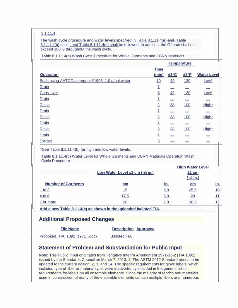
8.1.11.4
The wash cycle procedure and water levels specified in Table 8.1.11.4(a) and ,Table 8.1.11.4(b) shall , and Table 8.1.11.4(c) shall be followed. In addition, the G force shall not exceed 100 G throughout the wash cycle.
Table 8.1.11.4(a) Wash Cycle Procedure for Whole Garments and CBRN Materials
Temperature
Operation
Time
.
(min) ±3°C ±5°F Water Level
Suds using AATCC detergent #1993, 1.0 g/gal water 10 49 120 Low*
Drain 1 — — —
Carry-over 5 49 120 Low*
Drain 1 — — —
Rinse 2 38 100 High*
Drain 1 — — —
Rinse 2 38 100 High*
Drain 1 — — —
Rinse 2 38 100 High*
Drain 1 — — —
Extract 5 — — —
*See Table 8.1.11.4(b) for high and low water levels.
Table 8.1.11.4(b) Water Level for Whole Garments and CBRN Materials Operation Wash Cycle Procedure
Low Water Level ±1 cm ( 3⁄8 in.)
High Water Level
.
±1 cm
.
( 3⁄8 in.)
Number of Garments cm in. cm in.
1 to 3 15 5.9 25.5 10
4 to 6 17.5 6.9 28 11
7 or more 20 7.9 30.5 12
Add a new Table 8.11.4(c) as shown in the uploaded balloted TIA.
Additional Proposed Changes
File Name Description Approved
Proposed_TIA_1092_1971_.docx Balloted TIA
Statement of Problem and Substantiation for Public Input
Note: This Public Input originates from Tentative Interim Amendment 1971-13-2 (TIA 1092) issued by the Standards Council on March 7, 2013. 1. The ASTM 2412 Standard needs to be updated to the current edition. 2, 3, and 14. The specific requirements for glove labels, which included type of fiber or material type, were inadvertently included in the generic list of requirements for labels on all ensemble elements. Since the majority of fabrics and materials used in construction of many of the ensemble elements contain multiple fibers and numerous

blends, even attempting to include this level of detail on every product label would cause mass confusion. The issue becomes even more exacerbated by the minimum font sizes required on label text and by a garment specific label requirement, also included in the generic list, which mandates explicit component names as per the certification listing. This change provides the generic requirements for all labels, and then separates the specific ensemble element label requirements into subsets to avoid any interpretation issues. 4. The NFPA 1971 proposal (1971-46, Log CP-50) neglected to include the test method reference to Section 8.4 as well as the requirement for char length. NFPA 1971, 2013 edition references several flame resistance tests. It is important the standard references the correct flame resistance test and section number to insure the correct testing procedures are being followed. It was also the technical committee’s intent, based on historical data, to have the glove interface component evaluated for char length in addition to afterflame. 5. The NFPA 1971 proposal (1971-46, Log CP-50) neglected to include the test method reference to Section 8.4 as well as the requirement for char length. NFPA 1971, 2013 edition references several flame resistance tests. It is important the standard references the correct flame resistance test and section number to insure the correct testing procedures are being followed. It was also the technical committee’s intent, based on historical data, to have the glove extension component evaluated for char length in addition to afterflame. 6. This change brings this requirement in line with EN ISO 20345:2011. 7. The current laundering method described in Section 8.1.11 only accounts for water levels when laundering garments and CBRN Materials. The 2013 edition of NFPA 1971 now requires gloves and glove pouches to be laundered using Section 8.1.11 as a precondition. However a table for gloves and glove pouch water levels were not included. The water levels for the glove and glove pouch wash cycle needs to be specified in NFPA 1971, 2013 edition in order to allow for the front load wash machines to be properly programmed at the testing laboratories. The highest water levels currently in the standard were chosen to account for usage of both 35 lb and 50 lb capacity front-loading machines. The higher levels will also accommodate a full load of gloves/glove pouches and eliminate any risk associated with residual detergent. 8, 9, 15 and 16. Some changes made to the way the measurement of hood shrinkage were specified in cleaning shrinkage as part of the NFPA 1971-2013 revision would prevent any hood from being certified to the new requirements. There was also an inconsistency between how hood shrinkage was evaluated for both thermal and cleaning shrinkage for the interpretation of test results that would lead to inconsistent determinations of compliance among testing laboratories. The proposed changes using the same approach established in the 2007 edition of NFPA 1971 for applying cleaning shrinkage criteria while clarifications have been made for interpretation of permitted shrinkage in both cleaning and thermal shrinkage test methods. 10. NFPA 1971, 2013 edition has sections for glove pouch construction, sections 8.1.15 and 8.1.16. Section 8.27.8.2, section for Liquid Penetration Resistance, should reference section 8.1.16 for moisture barrier testing. 11. NFPA 1971, 2013 edition has sections for glove pouch construction, sections 8.1.15 and 8.1.16. Section 8.28.8.2, section for Viral Penetration Resistance, should reference section 8.1.16 for moisture barrier testing. 12. The ISO 13287 standard does not provide criteria for the evaluation of systematic increase or decrease of values. Also, the current calibration language is not clear. 13. The test apparatus will be maxed out if the test subject uses their arm’s range of motion to perform this test. In order to achieve more accurate results it is important the test subject use their wrist’s range of motion to perform this test. Emergency Nature: This TIA seeks to correct errors and omissions that were overlooked during the Fall 2013 revision cycle process of NFPA 1971. Additionally, some parts of this TIA correct circumstances in which the standard could adversely impact a method or product that was inadvertently overlooked in the total revision process.
Submitter Information Verification
Submitter Full Name:
TC on FAE-SPF
Organization: TC on Structural and Proximity Fire Fighting Protective Clothing and Equipment
Street Address:
City:
State:
Zip:
Submittal Date: Fri Aug 09 14:22:15 EDT 2013
Public Input No. 81-NFPA 1971-2015 [ Section No. 8.1.11.12 ]
8.1.11.12
Gloves and glove pouches shall be tumbled for 60 minutes and shall be removed immediately at the end of the drying cycle. At the conclusion of the final drying cycle, the glove or glove pouches shall be dried on a forced-air, non–tumble drying mechanism operated at 10ºC + /-2°C 5°C above current room temperature until dry but not for less than 8 hours.
Statement of Problem and Substantiation for Public Input
Makes the test tolerance consistent based on previous edition testing.
Submitter Information Verification
Submitter Full Name: Michael McKenna
Organization: Michael McKenna & Associates,
Street Address:
City:
State:
Zip:
Submittal Date: Mon Apr 06 14:32:51 EDT 2015
Public Input No. 149-NFPA 1971-2015 [ Section No. 8.1.18 ]
8.1.18* Glove Test Areas.
The glove test areas shall be as described in this paragraph and as shown in Figure 8.1.18, with the glove test area abbreviations designated as follows:
(1) P = palm; B = back; S = side.
(2) A-P: Palm side of hand from finger crotch line to 1⁄3 of the way down (grasp area)
(3) B-P: Palm side of hand from 1⁄3 of the way down (grasp area) to the wrist crease
(4) C-P: Palm side of hand from the wrist crease to 50 mm (2 in.) past the wrist crease
(5) D-P: Palm side of thumb
(6) E-P: Palm side of tip of thumb
(7) F-P: Palm side of index finger
(8) G-P: Palm side of fingertip of index finger
(9) H-P: Palm side of nonindex fingers
(10) I-P: Palm side of fingertip of nonindex fingers
(11) A-PS: Sides of hand adjacent to area A-P
(12) B-PS: Outside of hand adjacent to section B-P
(13) C-PS: Sides of hand adjacent to area C-P
(14) D-PS: Outside of thumb adjacent to area D-P
(15) E-PS: Inside of thumb adjacent to area D-P
(16) F-PS: Outside of index finger adjacent to area F-P
(17) H-PS: Between fingers adjacent to areas F-P and H-P
(18) I-PS: Outside of and adjacent to the smallest finger
(19) A-B: Back side of hand from finger crotch line to 1⁄3 of the way down (knuckle area)
(20) B-B: Back side of hand from 1⁄3 of the way down (knuckle area) to the wrist crease
(21) C-B: Back side of hand from the wrist crease to 50 mm (2 in.) past the wrist crease
(22) D-B: Back side of thumb
(23) E-B: Back side of tip of thumb
(24) F-B: Back side of index finger
(25) G-B: Back side of fingertip of index finger
(26) H-B: Back side of nonindex fingers
(27) I-B: Back side of fingertip of nonindex fingers
(28) A-BS: Sides of hand adjacent to area A-B
(29) B-BS: Outside of hand adjacent to area B-B
(30) C-BS: Sides of hand adjacent to area C-B
(31) D-BS: Outside of thumb adjacent to area D-B
(32) E-BS: Inside of thumb adjacent to area D-B
(33) F-BS: Outside of index finger adjacent to area F-B
(34) H-BS: Between fingers adjacent to areas F-B and H-B
(35) I-BS: Outside of and adjacent to the smallest finger
Figure 8.1.18 Glove Test Areas.
Additional Proposed Changes
File Name Description Approved
Figure_8.1.18.png Figure 8.1.18 with section highlighted for change. The highlighted E-P should be E-B.
Statement of Problem and Substantiation for Public Input
Editorial. Typo in figure. The highlighted E-P should be E-B.
Submitter Information Verification
Submitter Full Name: ROBIN TUTOR
Organization: UL LLC
Street Address:
City:
State:
Zip:
Submittal Date: Mon Jun 29 12:52:50 EDT 2015
Public Input No. 44-NFPA 1971-2014 [ Section No. 8.2.5.1 ]
8.2.5.1
Flame resistance testing shall be performed in accordance with ASTM D 6413, Standard Test Method for Flame Resistance of Textiles (Vertical Test). Fabric tear weights in Gr
ams s hall be determined based on "as received" samples including all FR treatments and coatings.
Statement of Problem and Substantiation for Public Input
ASTM D6413-99 has a note that directs the tear weight to be determined based on uncoated fabric weights, however, for our application it is more appropriate to use "as received" fabric weights. Additionally the Tearing Force chart has inconsistencies in the conversion factors from grams to ounces often resulting in different tear weights being utilized.
Submitter Information Verification
Submitter Full Name: Jason Allen
Organization: Intertek Testing Services
Street Address:
City:
State:
Zip:
Submittal Date: Tue Jul 01 14:35:57 EDT 2014
Public Input No. 43-NFPA 1971-2014 [ Section No. 8.2.6.1 ]
8.2.6.1
Afterflame time and char length shall be recorded and reported for each specimen. The average afterflame time and char length for each material in each direction tested shall be calculated, reported, and recorded. The afterflame time shall be recorded and reported to the nearest 0.2 1 second and the char length to the nearest 3 1 mm ( 1⁄8 25 in.).
Statement of Problem and Substantiation for Public Input
These changes improve the accuracy of the test method and are easily accomplished with common laboratory equipment
Submitter Information Verification
Submitter Full Name: Jason Allen
Organization: Intertek Testing Services
Street Address:
City:
State:
Zip:
Submittal Date: Tue Jul 01 14:29:03 EDT 2014
Public Input No. 173-NFPA 1971-2015 [ Section No. 8.3.5.1 ]
8.3.5.1
The helmet shall be positioned on the ISO size J headform specified in Figure 8.16.4.1 according to the HPI as described in 8.1.14.
Statement of Problem and Substantiation for Public Input
Editorial. Adding reference for HPI information.
Submitter Information Verification
Submitter Full Name: ROBIN TUTOR
Organization: UL LLC
Street Address:
City:
State:
Zip:
Submittal Date: Wed Jul 01 15:37:35 EDT 2015
Public Input No. 67-NFPA 1971-2015 [ Section No. 8.4.1.1 ]
8.4.1.1
This test method shall apply to protective glove bodiesbody, glove interface components, and glove extension composites.
Statement of Problem and Substantiation for Public Input
Editorial change.
Submitter Information Verification
Submitter Full Name: Michael McKenna
Organization: Michael McKenna & Associates,
Street Address:
City:
State:
Zip:
Submittal Date: Wed Apr 01 13:49:49 EDT 2015
Public Input No. 101-NFPA 1971-2015 [ Section No. 8.4.2 ]
8.4.2 Specimens.
Three specimens shall be tested for each material. Three specimens shall be tested after the preconditioning specified in 8.1.3. Three additional specimens shall be tested after the preconditioning specified in 8.1.11 followed by the preconditioning specified in 8.1.3.
Statement of Problem and Substantiation for Public Input
Clarifying that two sets of specimens are to be tested; one following laundering conditioning and one following room temperature conditioning.
Submitter Information Verification
Submitter Full Name: ROBIN TUTOR
Organization: UL LLC
Street Address:
City:
State:
Zip:
Submittal Date: Tue May 19 11:06:48 EDT 2015
Public Input No. 150-NFPA 1971-2015 [ Section No. 8.4.9.3 ]
8.4.9.3
For glove interface component composites, samples for conditioning shall be in the form of a 200 mm × 200 mm (8 in. × 8 in.) pouch as described in 8.1.15.
Statement of Problem and Substantiation for Public Input
Editorial. The referenced pouch wording in 8.1.15 provides the pouch dimensions. It is redundant to have the dimensions given here and defeats the purpose of having one section to provide pouch instructions.
Submitter Information Verification
Submitter Full Name: ROBIN TUTOR
Organization: UL LLC
Street Address:
City:
State:
Zip:
Submittal Date: Mon Jun 29 13:00:10 EDT 2015
Public Input No. 100-NFPA 1971-2015 [ New Section after 8.4.10.3 ]
New After 8.4.10.3: Three specimens shall be tested after the preconditioning specified in
8.1.3. Three additional specimens shall be tested after the preconditioning specified in 8.1.2 followed by the preconditioning specified in 8.1.3.
Statement of Problem and Substantiation for Public Input
Prior to the last edition, the laundering method for glove wristlet materials was 8.1.2 (home laundering method). During the last revision cycle, the laundering method for glove wristlet materials was inadvertently changed to a less stringent commercial laundering method 8.1.11. This input will correct this oversight and bring back consistency for the preconditioning of wristlet materials prior to flame testing as garment wristlet materials receive home laundering. Further the other glove wristlet tests (TPP and Cut Resistance) also require home laundering preconditioning.
Submitter Information Verification
Submitter Full Name: ROBIN TUTOR
Organization: UL LLC
Street Address:
City:
State:
Zip:
Submittal Date: Tue May 19 10:03:31 EDT 2015
Public Input No. 151-NFPA 1971-2015 [ Section No. 8.4.10.4 ]
8.4.10.4
After conditioning, the material shall be cut to form 50 mm × 150 mm (2 in. × 6 in.) specimens for testing. Specimens shall not include seams where multiple layers are involved. The swatch shall be permitted to be left stitched, restituted, or otherwise held together at the ends of the swatch for placement on the test apparatus. No stitching or binding mechanism shall be used in the test area.
Statement of Problem and Substantiation for Public Input
Editorial. The wording is used in sections involving swatches rather than wristlet tubing. The wording is not applicable to this section or is redundant.
Submitter Information Verification
Submitter Full Name: ROBIN TUTOR
Organization: UL LLC
Street Address:
City:
State:
Zip:
Submittal Date: Mon Jun 29 13:04:16 EDT 2015
Public Input No. 152-NFPA 1971-2015 [ Section No. 8.4.11.3 ]
8.4.11.3
For glove extension composites, samples for conditioning shall include glove material that is a minimum of 200 mm × 200 mm (8 in. × 8 in.) square consisting of the composite used in the actual glove extension construction with the layers arranged in proper order and stitched with the same thread used in the construction of the glove extension.be in the form of a pouch as described in 8.1.15.
Statement of Problem and Substantiation for Public Input
Editorial. Pouch reference was accidentally left out of this section during last revision cycle. This wording is consistent with the wording in all other glove composite tests.
Submitter Information Verification
Submitter Full Name: ROBIN TUTOR
Organization: UL LLC
Street Address:
City:
State:
Zip:
Submittal Date: Mon Jun 29 13:07:18 EDT 2015
Public Input No. 184-NFPA 1971-2015 [ Section No. 8.6.4 ]
8.6.4 Apparatus.
8.6.4.1
The test oven shall be as specified in ISO 17493, Clothing and equipment for protection against heat — Test method for convective heat resistance using a hot air circulating oven. Testing shall be carried out such that the center of the oven is at a temperature of 260°C, + 6/-0°C (500°F, + 10/-0°F). To accomplish such, it shall be necessary to establish a sensing thermocouple compensated setting (STCS) as described in 8.6.4.2.
8.6.4.2
Prior to commencement of testing each day, a thermocouple of equal type and performance as the oven sensing thermocouple shall be installed in the center of an empty oven.
8.6.4.3
With the oven door closed and air circulation activated, the empty oven shall be activated and its temperature control increased until the thermocouple installed in the center of the oven reaches a temperature of 260°C, +6/-0°C (500°F, +10/-0°F. The measurements made in 8.6.4.2 shall be repeated at horizontal and vertical extremes for the position the
specimen(s) will occupy when set in the oven for heat resistance resting as shown by the grid illustrated in Figure8.6.4.2. The results of measurements at each corner of the cube shall be averaged with the center of the oven to establish an overall The Sensing Thermocouple Compensated Setting (STCS).
8.6.4.4
The center of the oven shall then be maintained at a temperature of 260°C, + 6/-0°C (500°F, + 10/-0°F) for 5 minutes while recording the center oven thermocouple reading and sensing thermocouple reading at the end of each 30-second period for the 5-minute duration.
8.6.4.5
The difference in the two thermocouple readings shall be calculated for each of the 10 periods and then averaged to determine an average correction factor (ACF) in degrees Celsius or Fahrenheit.
8.6.4.6
The sensing thermocouple compensated setting (STCS) shall then be calculated as the ACF (in the appropriate units) plus 260°C, + 6/-0°C (500°F, + 10/-0°F).
Additional Proposed Changes
File Name Description Approved
Hold_1971-110_Log_114_Comment_on_Proposal_1971-99.pdf
NFPA 1971, 1971-110 Log 114
Statement of Problem and Substantiation for Public Input
Note: This Public Input appeared as "Reject but Hold" in Public Comment No. 1971-110, Log 114 of the F2011 Second Draft Report for NFPA 1971 and per the Regs. at 4.4.8.3.1. Substantiation: The proposed revisions are a step in the right direction for improving interlaboratory consistency for ensuring that test items are exposed to the specific temperature. Nevertheless, as different type of elements and components are subjected to oven heat resistance testing, a greater level of scrutiny is required to ensure that the temperature profile within the oven meets a certain tolerance. This is important for particularly large items such as footwear and helmets that within the oven meets a certain tolerance. This is important for particularly large items such as footwear and helmets that have a relatively high mass compared to smaller items such as flat material and hardware specimens. Some temperature mapping is needed to determine the ability of the oven to provide consistent temperature exposures of these items.
Submitter Information Verification
Submitter Full Name:
TC ON FAE-SPF
Organization: NFPA Technical Committee on Structral and Proximity Fire Fighting Protective Clothing and Equipment
Street Address:
City:
State:
Zip:
Submittal Date: Thu Jul 02 11:41:13 EDT 2015
Public Input No. 47-NFPA 1971-2014 [ Section No. 8.6.4.6 ]
8.6.4.6
The sensing thermocouple compensated setting (STCS) shall then be calculated as the ACF (in the appropriate units) plus 260°C, +6/-0°C (500°F, +10/-0°F).
Statement of Problem and Substantiation for Public Input
The current language may be interpretted multiple ways. This clarification further eliminates ambiguity.
Submitter Information Verification
Submitter Full Name: Jason Allen
Organization: Intertek Testing Services
Street Address:
City:
State:
Zip:
Submittal Date: Tue Jul 01 15:18:04 EDT 2014
Public Input No. 218-NFPA 1971-2015 [ Section No. 8.6.12.2 ]
8.6.12.2
Three complete helmet specimens shall be tested.
Helmet specimens shall include all components required in 6.5.2 or 6.6.2 as appropriate for the evaluation of structural fire fighting protective helmet elements or proximity fire fighting protective helmet elements, respectively.
Statement of Problem and Substantiation for Public Input
A recent TIA to NFPA 1971-2013 attempted to reconcile differences between the testing practices of certification organizations but was over generalized to address the specific topic that created the issues in the first place. The proposed changes addresses the matter of an unqualified faceshield being used on a helmet when the manufacturer also provided goggles that are qualified as a component of the helmet. This particular input addresses an associated change in the test method.
Related Public Inputs for This Document
Related Input Relationship
Public Input No. 217-NFPA 1971-2015 [Section No. 6.5.2] Parent log
Submitter Information Verification
Submitter Full Name: JEFFREY STULL
Organization: INTERNATIONAL PERSONNEL PROTECTION, INC.
Street Address:
City:
State:
Zip:
Submittal Date: Mon Jul 06 04:15:49 EDT 2015
Public Input No. 198-NFPA 1971-2015 [ Section No. 8.6.13 ]
8.6.13 Specific Requirements for Testing Gloves.
8.6.13.1
Samples for conditioning shall be whole gloves.
8.6.13.2
Conditioning shall be performed as specified in 8.1.11.
8.6.13.3
Specimens shall include complete gloves with labels.
8.6.13.4
The minimum interior dimensions of the test oven shall be 610 mm × 610 mm × 610 mm (24 in. × 24 in. × 24 in.).
8.6.13.5
The glove body shall be filled to capacity with nominal 4 mm ( 1⁄8 in.) sized perforated soda-lime or borosilicate glass beads. The glass beads shall be tightly packed into the fingers of the glove and glove body and shall be 21°C ± 3°C (71°F ± 5°F). The opening of the glove shall be clamped together, and the specimen shall be suspended by the clamp in the oven so that the entire glove is not less than 50 mm (2 in.) from any oven surface and not less than 150 mm (6 in.) from any other specimen, and airflow is parallel to the plane of the material. One to three glove specimens shall be placed in the test oven at one time. The glove specimens shall be suspended such that each specimen is the same distance from the airflow source, so that no glove sample is blocking the airflow to other glove samples.
8.6.13.6
The glove specimen dimensions also shall be measured to determine pass or fail. The length measurement of the glove specimen shall be from the tip of the middle finger to the end of the glove body on the palm side. The width measurement of the glove specimen shall be the width measurement on the palm side 25 mm (1 in.) below the base of the fingers.
8.6.13.7
The percent change in the width and length dimensions of each specimen shall be calculated. Results shall be recorded and reported as the average of all three specimens in each dimension.
8.6.13.8
Specimens shall be donned and flexed as specified in 8.1.10 before and after the heat exposure.
8.6.13.9
Testing shall be performed as specified in 8.6.2 through 8.6.7.
8.6.13 Specific Requirements for Testing Gloves.
8.6.13.1 Samples for conditioning shall be whole gloves in size large.
8.6.13.2 The glove specimen dimensions shall be measured. The length measurement of the
glove specimen shall be from the tip of the middle finger to the end of the glove body on the palm side. The width measurement of the glove specimen shall be the width measurement on the palm side 25 mm (1 in.) below the base of the fingers.
8.6.13.2 3 Then the gloves shall be conditioned Conditioning shall be performed as specified in
8.1.11.
8.6.13.3 Specimens shall include complete gloves with labels.
8.6.13.4 The minimum interior dimensions of the test oven shall be 610 mm × 610 mm × 610
mm (24 in. × 24 in. × 24 in.).
8.6.13.5 4 Then t The glove body shall be filled to capacity with nominal 4 mm (1⁄8 in.) sized
perforated soda-lime or borosilicate glass beads. A total of 51 ml of beads shall be evenly distributed into the fingers. 372 ml of beads shall be placed into a mesh bag. The bag shall be loosely cinched to keep the beads from spilling out. The mesh bag filled with beads shall be placed into the body of the glove. The glass beads shall be tightly packed into the fingers of the glove and glove body and shall be 21°C ± 3°C (71°F ± 5°F). The opening of the glove shall be clamped together, and the specimen shall be suspended by the clamp in the oven so that the entire glove is not less than 50 mm (2 in.) from any oven surface and not less than 150 mm (6 in.) from any other specimen, and airflow is parallel to the plane of the material. One to three glove specimens shall be placed in the test oven at one time. The glove specimens shall be suspended such that each specimen is the same distance from the airflow source, so that no glove sample is blocking the airflow to other glove samples.
8.6.13.6 5 After oven exposure, t The glove specimen dimensions also shall be measured as
described in 8.6.13.2 to determine pass or fail. The length measurement of the glove specimen shall be from the tip of the middle finger to the end of the glove body on the palm side. The width measurement of the glove specimen shall be the width measurement on the palm side 25 mm (1 in.) below the base of the fingers.
8.6.13.7 6 The percent change in the width and length dimensions of each specimen shall be
calculated. Results shall be recorded and reported as the average of all three specimens in each dimension.
8.6.13.8 7 Specimens shall be donned and flexed as specified in 8.1.10 before and after the
heat exposure.
8.6.13.9 8 Testing shall be performed as specified in 8.6.2 through 8.6.7.
Statement of Problem and Substantiation for Public Input
Revised test method based on the continuing research by Harry Winer and the Glove Task Group.
Submitter Information Verification
Submitter Full Name: MICHAEL MCKENNA
Organization: MICHAEL MCKENNA ASSOCIATES
Street Address:
City:
State:
Zip:
Submittal Date: Thu Jul 02 15:38:15 EDT 2015
Public Input No. 229-NFPA 1971-2015 [ Section No. 8.6.13.5 ]
8.6.13.5
The glove body shall be filled to capacity with nominal 4 mm ( 1⁄8 in.) sized perforated soda-lime or borosilicate glass beads. The glass beads shall be tightly packed into the fingers of the glove and glove body and with the PTFE glove body form shown in figure XXX. The glove body form shall be 21°C ± 3°C (71°F ± 5°F). The opening of the glove shall be clamped together at the wrist crease of the form, and the specimen shall be suspended by the clamp top hook of the form in the oven so that the entire glove is not less than 50 mm (2 in.) from any oven surface and not less than 150 mm (6 in.) from any other specimen, and airflow is parallel to the plane of the material. One to three glove specimens shall be placed in the test oven at one time. The glove specimens shall be suspended such that each specimen is the same distance from the airflow source, so that no glove sample is blocking the airflow to other glove samples.
Additional Proposed Changes
File Name Description Approved
Glove_H_T_Fixture.jpg PTFE Glove Body form
Statement of Problem and Substantiation for Public Input
Glove beads settle towards the knuckle area of a glove when the glove is hung in the oven. The proposed form gives a rigid form to fill the glove in a repeatable manner.
Submitter Information Verification
Submitter Full Name: JASON ALLEN
Organization: INTERTEK TESTING SERVICES
Street Address:

City:
State:
Zip:
Submittal Date: Mon Jul 06 12:34:50 EDT 2015
Public Input No. 237-NFPA 1971-2015 [ Section No. 8.6.13.5 ]
8.6.13.5
The glove body shall be filled to capacity with nominal 4 mm ( 1⁄8 in.) sized perforated soda-lime or borosilicate glass beads. The glove fingers shall be filled with 15mm (5/8 in) diameter PTFE rod 2.25" long The glass beads shall be tightly packed into the fingers of the glove and glove body and shall be 21°C ± 3°C (71°F ± 5°F). The opening of the glove shall be clamped together, and the specimen shall be suspended by the clamp in the oven so that the entire glove is not less than 50 mm (2 in.) from any oven surface and not less than 150 mm (6 in.) from any other specimen, and airflow is parallel to the plane of the material. One to three glove specimens shall be placed in the test oven at one time. The glove specimens shall be suspended such that each specimen is the same distance from the airflow source, so that no glove sample is blocking the airflow to other glove samples.
Statement of Problem and Substantiation for Public Input
The proposed rods are easier to use to be sure that fingers are properly filled prior to the heat test.
Submitter Information Verification
Submitter Full Name: JASON ALLEN
Organization: INTERTEK TESTING SERVICES
Street Address:
City:
State:
Zip:
Submittal Date: Mon Jul 06 14:00:16 EDT 2015
Public Input No. 243-NFPA 1971-2015 [ New Section after 8.6.13.6 ]
TITLE OF NEW CONTENT
Type your content here ...The PTFE Glove hand form seen in Figure XXXX shall be pulled out perpendicular to the top plane of the form utilizing a force gauge and the force shall be noted
Additional Proposed Changes
File Name Description Approved
Glove_H_T_Fixture.jpg Glove Heat and Thermal Handform and pullout form
Statement of Problem and Substantiation for Public Input
This form attempts to measure the difficulty donning/doffing post heat exposure by utilizing a measurable characteristic
Submitter Information Verification
Submitter Full Name: JASON ALLEN
Organization: INTERTEK TESTING SERVICES
Street Address:
City:
State:
Zip:
Submittal Date: Mon Jul 06 14:21:11 EDT 2015
Public Input No. 203-NFPA 1971-2015 [ Section No. 8.6.14.2 ]
8.6.14.2
Footwear specimens for testing Specimens shall be size 9the whole footwear in men's size 9D, medium width.
Statement of Problem and Substantiation for Public Input
Section 8.6.14.2 specifies footwear to be tested should be size 9 but the other tests that specify size are more specific (size 9D, medium width), this change will make 8.6.14.2 consistent with similar tests. In addition, greater specificity here may be important because the boot is flexed and the size dictates how many beads are used in the test.
Submitter Information Verification
Submitter Full Name: MARNI SCHMID
Organization: FORTUNES COLLIDE MARKETING LLC
Street Address:
City:
State:
Zip:
Submittal Date: Fri Jul 03 21:38:28 EDT 2015
Public Input No. 159-NFPA 1971-2015 [ Section No. 8.6.14.9 ]
8.6.14.9
Following removal from the oven, the specimen shall be allowed to cool at room temperature for not less than 5 minutes, + 15/-0 seconds. Within 10 minutes, + 15/-0 seconds, after removal from the oven, the test specimen shall be examined inside and outside for evidence of melting, separation, or ignition. Footwear separation of 1.4 mm × 18 mm (0.55 055 in. × 0.71 in.) or more in any orientation shall be recorded and reported.
Statement of Problem and Substantiation for Public Input
Editorial. Typo in conversion.
Submitter Information Verification
Submitter Full Name: ROBIN TUTOR
Organization: UL LLC
Street Address:
City:
State:
Zip:
Submittal Date: Mon Jun 29 14:55:19 EDT 2015
Public Input No. 82-NFPA 1971-2015 [ Section No. 8.6.14.11 ]
8.6.14.11
Footwear functionality shall be determined by flexing the specimen for 100,000 cycles performed in accordance with Appendix B of FIA 1209, Whole Shoe Flex, with the following modifications:
(1) Water shall not be used.
(2) The flex speed shall be 60 cycles/min, + /- 2 cycles/min.
(3) Alternative flexing equipment shall be permitted to be used .
The flex equipment used shall meet
(3) when the flexing equipment meets the following
criteria
(3) parameters:
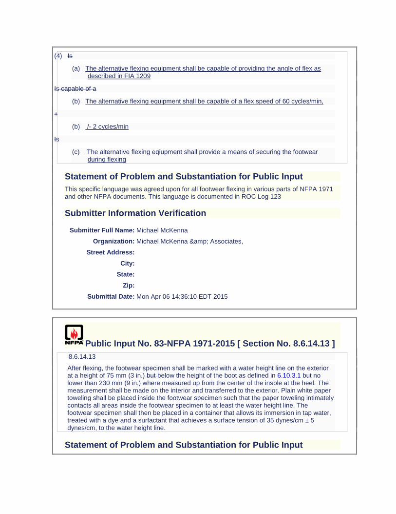
(4) Is
(a) The alternative flexing equipment shall be capable of providing the angle of flex as described in FIA 1209
Is capable of a
(b) The alternative flexing equipment shall be capable of a flex speed of 60 cycles/min,
+
(b) /- 2 cycles/min
Is
(c) The alternative flexing eqiupment shall provide a means of securing the footwear during flexing
Statement of Problem and Substantiation for Public Input
This specific language was agreed upon for all footwear flexing in various parts of NFPA 1971 and other NFPA documents. This language is documented in ROC Log 123
Submitter Information Verification
Submitter Full Name: Michael McKenna
Organization: Michael McKenna & Associates,
Street Address:
City:
State:
Zip:
Submittal Date: Mon Apr 06 14:36:10 EDT 2015
Public Input No. 83-NFPA 1971-2015 [ Section No. 8.6.14.13 ]
8.6.14.13
After flexing, the footwear specimen shall be marked with a water height line on the exterior at a height of 75 mm (3 in.) but below the height of the boot as defined in 6.10.3.1 but no lower than 230 mm (9 in.) where measured up from the center of the insole at the heel. The measurement shall be made on the interior and transferred to the exterior. Plain white paper toweling shall be placed inside the footwear specimen such that the paper toweling intimately contacts all areas inside the footwear specimen to at least the water height line. The footwear specimen shall then be placed in a container that allows its immersion in tap water, treated with a dye and a surfactant that achieves a surface tension of 35 dynes/cm ± 5 dynes/cm, to the water height line.
Statement of Problem and Substantiation for Public Input
Editorial. The word "but" does appear in ROC 1971-40 but it is a typo and makes the sentence confusing and illogical.
Submitter Information Verification
Submitter Full Name: Michael McKenna
Organization: Michael McKenna & Associates,
Street Address:
City:
State:
Zip:
Submittal Date: Mon Apr 06 14:41:21 EDT 2015
Public Input No. 120-NFPA 1971-2015 [ Section No. 8.6.16 ]
8.6.16 Specific Requirements for Testing Hoods.
8.6.16.1
Samples for conditioning shall include complete hoods, with labels.
8.6.16.2
Hoods shall be tested both before and after the conditioning specified in 8.1.2.
8.6.16.3
Testing shall be performed as specified in 8.6.4 through 8.6.6 unless modified herein.
8.6.16.4
Hoods shall be donned on a nonconductive test headform as specified in Figure 8.6.12.3. The dimensions of the face opening shall be measured as specified in 8.46.4.2 or 8.46.5.3. Measurements shall also be made at the back and both sides of the hood from the top of the hood to the basic plane. The location of the basic plane on the hood shall be marked at each location.
8.6.16.5
The headform with hood attached donned shall be placed in the center of the test oven with the centerline of the front of the hood facing the airflow.
8.6.16.6
The minimum interior dimensions of the test oven shall be 610 mm × 610 mm × 610 mm (24 in. × 24 in. × 24 in.).
8.6.16.7
The test thermocouple shall be positioned so that it is level with the horizontal centerline of a mount mounted test hood. The thermocouple shall be equidistant between the vertical centerline of a mounted test hood placed in the middle of the oven wall where the airflow enters the test chamber.
8.6.16.8
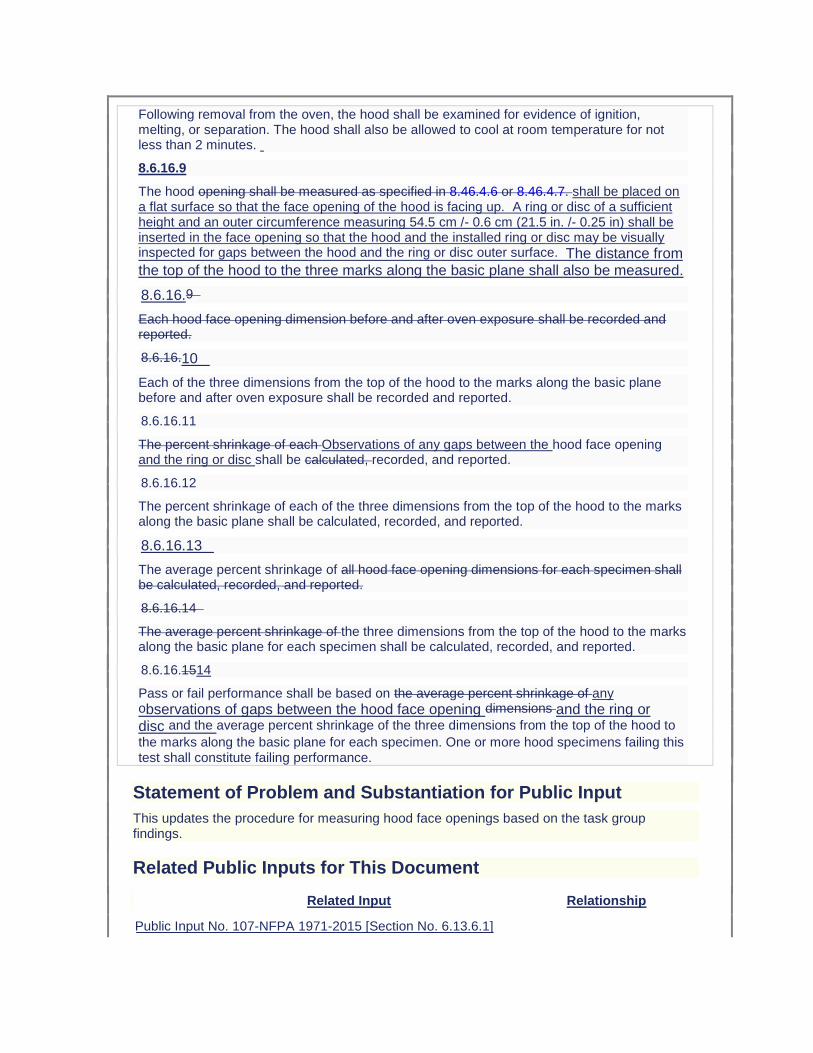
Following removal from the oven, the hood shall be examined for evidence of ignition, melting, or separation. The hood shall also be allowed to cool at room temperature for not less than 2 minutes.
8.6.16.9
The hood opening shall be measured as specified in 8.46.4.6 or 8.46.4.7. shall be placed on a flat surface so that the face opening of the hood is facing up. A ring or disc of a sufficient height and an outer circumference measuring 54.5 cm /- 0.6 cm (21.5 in. /- 0.25 in) shall be inserted in the face opening so that the hood and the installed ring or disc may be visually inspected for gaps between the hood and the ring or disc outer surface. The distance from the top of the hood to the three marks along the basic plane shall also be measured.
8.6.16.9
Each hood face opening dimension before and after oven exposure shall be recorded and reported.
8.6.16.10
Each of the three dimensions from the top of the hood to the marks along the basic plane before and after oven exposure shall be recorded and reported.
8.6.16.11
The percent shrinkage of each Observations of any gaps between the hood face opening and the ring or disc shall be calculated, recorded, and reported.
8.6.16.12
The percent shrinkage of each of the three dimensions from the top of the hood to the marks along the basic plane shall be calculated, recorded, and reported.
8.6.16.13
The average percent shrinkage of all hood face opening dimensions for each specimen shall be calculated, recorded, and reported.
8.6.16.14
The average percent shrinkage of the three dimensions from the top of the hood to the marks along the basic plane for each specimen shall be calculated, recorded, and reported.
8.6.16.1514
Pass or fail performance shall be based on the average percent shrinkage of any observations of gaps between the hood face opening dimensions and the ring or disc and the average percent shrinkage of the three dimensions from the top of the hood to
the marks along the basic plane for each specimen. One or more hood specimens failing this test shall constitute failing performance.
Statement of Problem and Substantiation for Public Input
This updates the procedure for measuring hood face openings based on the task group findings.
Related Public Inputs for This Document
Related Input Relationship
Public Input No. 107-NFPA 1971-2015 [Section No. 6.13.6.1]
Public Input No. 122-NFPA 1971-2015 [Section No. 7.13.4]
Submitter Information Verification
Submitter Full Name: AMANDA NEWSOM
Organization: UL LLC
Street Address:
City:
State:
Zip:
Submittal Date: Mon Jun 08 15:02:39 EDT 2015
Public Input No. 240-NFPA 1971-2015 [ Section No. 8.6.16.1 ]
8.6.16.1
Samples for conditioning shall include complete hoods, with labels; however, the dimensional change in the hood label(s) shall not be determined.
Statement of Problem and Substantiation for Public Input
Some ambiguity in the test method procedures was perceived during the education task group review of this test method. The proposed change is intended to clarify having the label as part of the tested sample/specimen but not evaluated for thermal shrinkage.
Submitter Information Verification
Submitter Full Name: JEFFREY STULL
Organization: INTERNATIONAL PERSONNEL PROTECTION,INC.
Street Address:
City:
State:
Zip:
Submittal Date: Mon Jul 06 14:09:52 EDT 2015
Public Input No. 10-NFPA 1971-2013 [ Sections 8.6.16.11, 8.6.16.12, 8.6.16.13, 8.6.16.14, 8.6.16... ]
Sections 8.6.16.11, 8.6.16.12, 8.6.16.13, 8.6.16.14, 8.6.16.15
8.6.16.11
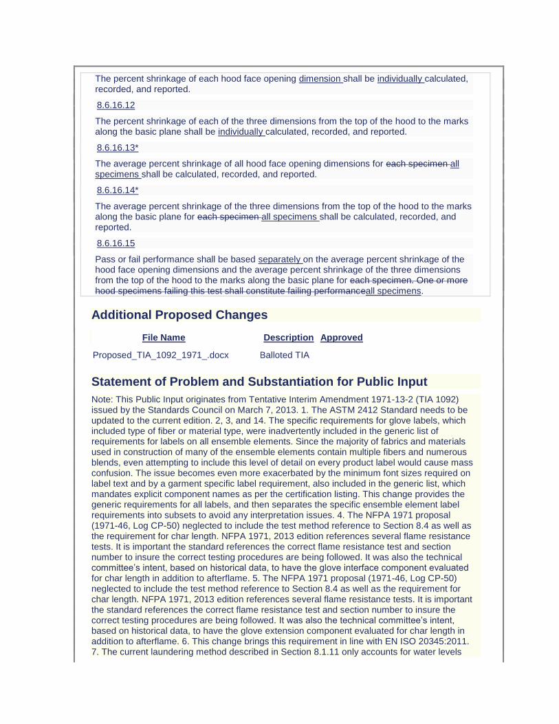
The percent shrinkage of each hood face opening dimension shall be individually calculated, recorded, and reported.
8.6.16.12
The percent shrinkage of each of the three dimensions from the top of the hood to the marks along the basic plane shall be individually calculated, recorded, and reported.
8.6.16.13*
The average percent shrinkage of all hood face opening dimensions for each specimen all specimens shall be calculated, recorded, and reported.
8.6.16.14*
The average percent shrinkage of the three dimensions from the top of the hood to the marks along the basic plane for each specimen all specimens shall be calculated, recorded, and reported.
8.6.16.15
Pass or fail performance shall be based separately on the average percent shrinkage of the hood face opening dimensions and the average percent shrinkage of the three dimensions from the top of the hood to the marks along the basic plane for each specimen. One or more hood specimens failing this test shall constitute failing performanceall specimens.
Additional Proposed Changes
File Name Description Approved
Proposed_TIA_1092_1971_.docx Balloted TIA
Statement of Problem and Substantiation for Public Input
Note: This Public Input originates from Tentative Interim Amendment 1971-13-2 (TIA 1092) issued by the Standards Council on March 7, 2013. 1. The ASTM 2412 Standard needs to be updated to the current edition. 2, 3, and 14. The specific requirements for glove labels, which included type of fiber or material type, were inadvertently included in the generic list of requirements for labels on all ensemble elements. Since the majority of fabrics and materials used in construction of many of the ensemble elements contain multiple fibers and numerous blends, even attempting to include this level of detail on every product label would cause mass confusion. The issue becomes even more exacerbated by the minimum font sizes required on label text and by a garment specific label requirement, also included in the generic list, which mandates explicit component names as per the certification listing. This change provides the generic requirements for all labels, and then separates the specific ensemble element label requirements into subsets to avoid any interpretation issues. 4. The NFPA 1971 proposal (1971-46, Log CP-50) neglected to include the test method reference to Section 8.4 as well as the requirement for char length. NFPA 1971, 2013 edition references several flame resistance tests. It is important the standard references the correct flame resistance test and section number to insure the correct testing procedures are being followed. It was also the technical committee’s intent, based on historical data, to have the glove interface component evaluated for char length in addition to afterflame. 5. The NFPA 1971 proposal (1971-46, Log CP-50) neglected to include the test method reference to Section 8.4 as well as the requirement for char length. NFPA 1971, 2013 edition references several flame resistance tests. It is important the standard references the correct flame resistance test and section number to insure the correct testing procedures are being followed. It was also the technical committee’s intent, based on historical data, to have the glove extension component evaluated for char length in addition to afterflame. 6. This change brings this requirement in line with EN ISO 20345:2011. 7. The current laundering method described in Section 8.1.11 only accounts for water levels
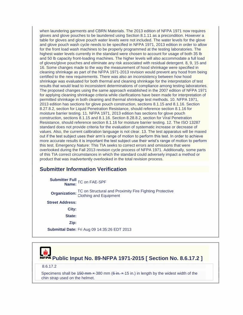
when laundering garments and CBRN Materials. The 2013 edition of NFPA 1971 now requires gloves and glove pouches to be laundered using Section 8.1.11 as a precondition. However a table for gloves and glove pouch water levels were not included. The water levels for the glove and glove pouch wash cycle needs to be specified in NFPA 1971, 2013 edition in order to allow for the front load wash machines to be properly programmed at the testing laboratories. The highest water levels currently in the standard were chosen to account for usage of both 35 lb and 50 lb capacity front-loading machines. The higher levels will also accommodate a full load of gloves/glove pouches and eliminate any risk associated with residual detergent. 8, 9, 15 and 16. Some changes made to the way the measurement of hood shrinkage were specified in cleaning shrinkage as part of the NFPA 1971-2013 revision would prevent any hood from being certified to the new requirements. There was also an inconsistency between how hood shrinkage was evaluated for both thermal and cleaning shrinkage for the interpretation of test results that would lead to inconsistent determinations of compliance among testing laboratories. The proposed changes using the same approach established in the 2007 edition of NFPA 1971 for applying cleaning shrinkage criteria while clarifications have been made for interpretation of permitted shrinkage in both cleaning and thermal shrinkage test methods. 10. NFPA 1971, 2013 edition has sections for glove pouch construction, sections 8.1.15 and 8.1.16. Section 8.27.8.2, section for Liquid Penetration Resistance, should reference section 8.1.16 for moisture barrier testing. 11. NFPA 1971, 2013 edition has sections for glove pouch construction, sections 8.1.15 and 8.1.16. Section 8.28.8.2, section for Viral Penetration Resistance, should reference section 8.1.16 for moisture barrier testing. 12. The ISO 13287 standard does not provide criteria for the evaluation of systematic increase or decrease of values. Also, the current calibration language is not clear. 13. The test apparatus will be maxed out if the test subject uses their arm’s range of motion to perform this test. In order to achieve more accurate results it is important the test subject use their wrist’s range of motion to perform this test. Emergency Nature: This TIA seeks to correct errors and omissions that were overlooked during the Fall 2013 revision cycle process of NFPA 1971. Additionally, some parts of this TIA correct circumstances in which the standard could adversely impact a method or product that was inadvertently overlooked in the total revision process.
Submitter Information Verification
Submitter Full Name:
TC on FAE-SPF
Organization: TC on Structural and Proximity Fire Fighting Protective Clothing and Equipment
Street Address:
City:
State:
Zip:
Submittal Date: Fri Aug 09 14:35:26 EDT 2013
Public Input No. 89-NFPA 1971-2015 [ Section No. 8.6.17.2 ]
8.6.17.2
Specimens shall be 150 mm × 380 mm (6 in. × 15 in.) in length by the widest width of the chin strap used on the helmet.
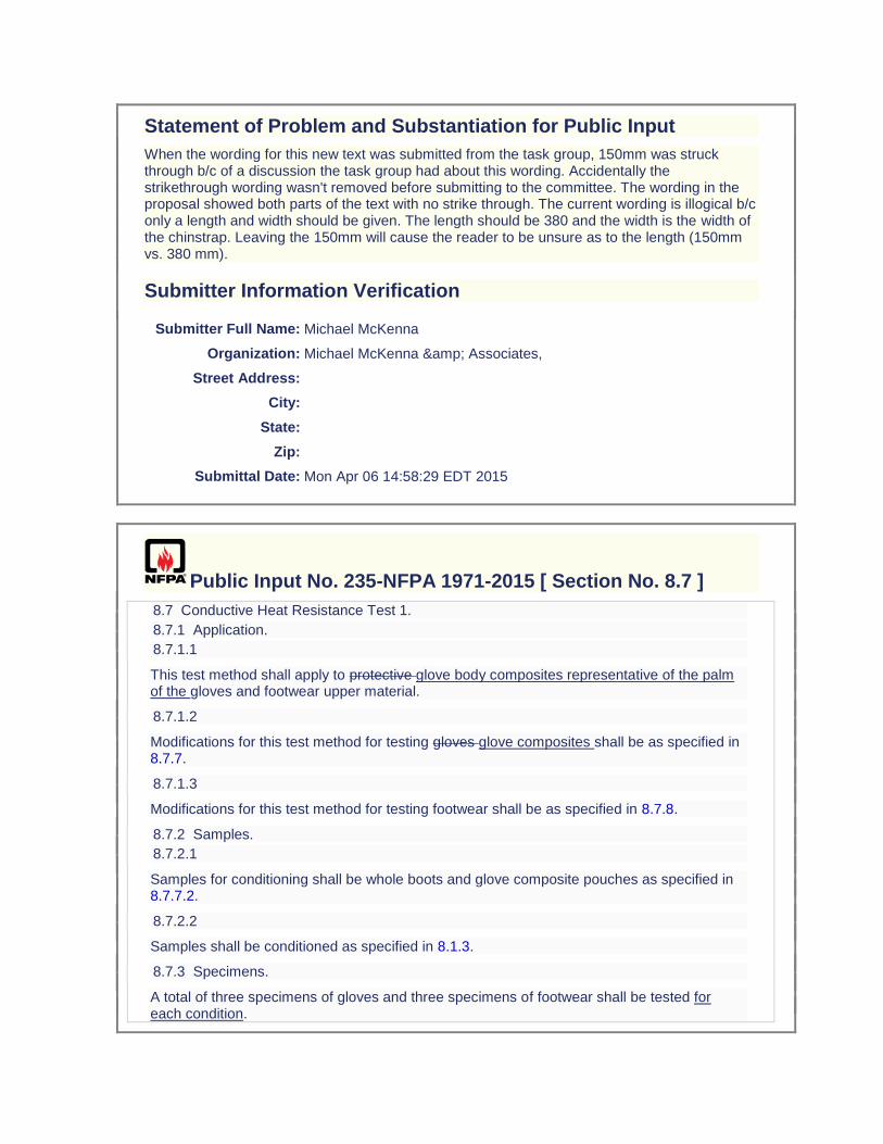
Statement of Problem and Substantiation for Public Input
When the wording for this new text was submitted from the task group, 150mm was struck through b/c of a discussion the task group had about this wording. Accidentally the strikethrough wording wasn't removed before submitting to the committee. The wording in the proposal showed both parts of the text with no strike through. The current wording is illogical b/c only a length and width should be given. The length should be 380 and the width is the width of the chinstrap. Leaving the 150mm will cause the reader to be unsure as to the length (150mm vs. 380 mm).
Submitter Information Verification
Submitter Full Name: Michael McKenna
Organization: Michael McKenna & Associates,
Street Address:
City:
State:
Zip:
Submittal Date: Mon Apr 06 14:58:29 EDT 2015
Public Input No. 235-NFPA 1971-2015 [ Section No. 8.7 ]
8.7 Conductive Heat Resistance Test 1.
8.7.1 Application.
8.7.1.1
This test method shall apply to protective glove body composites representative of the palm of the gloves and footwear upper material.
8.7.1.2
Modifications for this test method for testing gloves glove composites shall be as specified in 8.7.7.
8.7.1.3
Modifications for this test method for testing footwear shall be as specified in 8.7.8.
8.7.2 Samples.
8.7.2.1
Samples for conditioning shall be whole boots and glove composite pouches as specified in 8.7.7.2.
8.7.2.2
Samples shall be conditioned as specified in 8.1.3.
8.7.3 Specimens.
A total of three specimens of gloves and three specimens of footwear shall be tested for each condition.
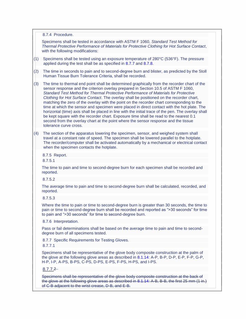
8.7.4 Procedure.
Specimens shall be tested in accordance with ASTM F 1060, Standard Test Method for Thermal Protective Performance of Materials for Protective Clothing for Hot Surface Contact, with the following modifications:
(1) Specimens shall be tested using an exposure temperature of 280°C (536°F). The pressure applied during the test shall be as specified in 8.7.7 and 8.7.8.
(2) The time in seconds to pain and to second-degree burn and blister, as predicted by the Stoll Human Tissue Burn Tolerance Criteria, shall be recorded.
(3) The time to thermal end point shall be determined graphically from the recorder chart of the sensor response and the criterion overlay prepared in Section 10.5 of ASTM F 1060, Standard Test Method for Thermal Protective Performance of Materials for Protective Clothing for Hot Surface Contact. The overlay shall be positioned on the recorder chart, matching the zero of the overlay with the point on the recorder chart corresponding to the time at which the sensor and specimen were placed in direct contact with the hot plate. The horizontal (time) axis shall be placed in line with the initial trace of the pen. The overlay shall be kept square with the recorder chart. Exposure time shall be read to the nearest 0.1 second from the overlay chart at the point where the sensor response and the tissue tolerance curve cross.
(4) The section of the apparatus lowering the specimen, sensor, and weighed system shall travel at a constant rate of speed. The specimen shall be lowered parallel to the hotplate. The recorder/computer shall be activated automatically by a mechanical or electrical contact when the specimen contacts the hotplate.
8.7.5 Report.
8.7.5.1
The time to pain and time to second-degree burn for each specimen shall be recorded and reported.
8.7.5.2
The average time to pain and time to second-degree burn shall be calculated, recorded, and reported.
8.7.5.3
Where the time to pain or time to second-degree burn is greater than 30 seconds, the time to pain or time to second-degree burn shall be recorded and reported as “>30 seconds” for time to pain and “>30 seconds” for time to second-degree burn.
8.7.6 Interpretation.
Pass or fail determinations shall be based on the average time to pain and time to second-degree burn of all specimens tested.
8.7.7 Specific Requirements for Testing Gloves.
8.7.7.1
Specimens shall be representative of the glove body composite construction at the palm of the glove at the following glove areas as described in 8.1.14: A-P, B-P, D-P, E-P, F-P, G-P, H-P, I-P, A-PS, B-PS, C-PS, D-PS, E-PS, F-PS, H-PS, and I-PS.
8.7.7.2
Specimens shall be representative of the glove body composite construction at the back of the glove at the following glove areas as described in 8.1.14: A-B, B-B, the first 25 mm (1 in.) of C-B adjacent to the wrist crease, D-B, and E-B.
8.7.7.3
For glove body composites, specimens for conditioning shall be in the form of a pouch as described in 8.1.15.
8.7.7.4
Specimens shall be tested after being subjected to the procedure specified in 8.1.3 both before and after laundering as specified in 8.1.2.
8.7.7.5
Specimens shall also be tested after being subjected to wet conditioning as specified in 8.1.8 both before and after laundering as specified in 8.21.11.
8.7.7.6
Testing shall be performed as specified in 8.7.2 through 8.7.6.
8.7.7.7
After the specimens are conditioned as specified in 8.7.7.3 and 8.7.7.5, the pouch and necessary stitching shall be cut to form 100 mm × 150 mm (4 in. × 6 in.) or 150 mm × 150 mm (6 in. × 6 in.) specimens for testing.
8.7.7.8
The pressure applied during the test shall be 3.45 kPa ± 0.35 kPa (0.5 psi ± 0.05 psi) for specimens representative of the glove body composite construction at the palm of the glove as described in 8.7.7.1.
8.7.7.9
The pressure applied during the test shall be 13.75 kPa ± 1.35 kPa (2 psi ± 0.2 psi) for specimens representative of the glove body composite construction at the back of the glove as described in
8
.7.7.2.
8.7.8 Specific Requirements for Testing Footwear Upper Materials.
8.7.8.1
Specimens shall consist of each composite of the footwear upper used in the actual footwear construction, including the tongue but excluding the gusset, with the layers arranged in proper order. Where a composite is identical to another composite except for additional reinforcement layer(s), the composite with no reinforcement layers shall be tested.
8.7.8.2
Testing shall be performed as specified in 8.7.2 through 8.7.6.
8.7.8.3
A pressure of 3.45 kPa ± 0.35 kPa (0.5 psi ± 0.05 psi) shall be applied during the test.
Statement of Problem and Substantiation for Public Input
A new test has been proposed to measuring the thermal insulation for the back of the gloves that is more consistent with the type of exposure that generally occurs for this portion of the gloves (radiant heat) as opposed to conductive heat resistance. The new test is based on use of the same radiant panel used for self-contained breathing apparatus facepieces and utilized a new wetting technique that provides a uniform mist exposure of the thermal barrier (innermost) layer of the glove composite to serve as a worse case wetting condition. The specimen holder, sensor, and data acquisition/data analysis system are similar to the equipment specified in
ASTM F1939 (RPP test). The test provided output as the time to a predicted second degree burn injury and an initial performance criterion of greater than 90 seconds has been proposed. The test method and sample conditioning technique are undergoing further validation and a limited interlaboratory test program is proposed over the fall of 2015 and early spring of 2016. The specific change indicated with this input is to limit the current conductive heat resistance test to the palm side of the gloves.
Related Public Inputs for This Document
Related Input Relationship
Public Input No. 231-NFPA 1971-2015 [Section No. 7.7.4] Parent log
Submitter Information Verification
Submitter Full Name: JEFFREY STULL
Organization: INTERNATIONAL PERSONNEL PROTECTION, INC.
Street Address:
City:
State:
Zip:
Submittal Date: Mon Jul 06 13:47:04 EDT 2015
Public Input No. 56-NFPA 1971-2014 [ Section No. 8.7.4 ]
8.7.4 Procedure.
Specimens shall be tested in accordance with ASTM F 1060, Standard Test Method for Thermal Protective Performance of Materials for Protective Clothing for Hot Surface Contact, with the following modifications:
(1) Specimens shall be tested using an exposure temperature of 280°C (536°F). The pressure applied during the test shall be as specified in 8.7.7 and 8.7.8.
(2) The time in seconds to pain and to second-degree burn and blister, as predicted by the Stoll Human Tissue Burn Tolerance Criteria, shall be recorded.
(4) The
time to thermal end point shall be determined graphically from the recorder chart of the sensor response and the criterion overlay prepared in Section 10.5 of ASTM F 1060, Standard Test Method for Thermal Protective Performance of Materials for Protective Clothing for Hot Surface Contact. The overlay shall be positioned on the recorder chart, matching the zero of the overlay with the point on the recorder chart corresponding to the time at which the sensor and specimen were placed in direct contact with the hot plate. The horizontal (time) axis shall be placed in line with the initial trace of the pen. The overlay shall be kept square with the recorder chart. Exposure time shall be read to the nearest 0.1 second from the overlay chart at the point where the sensor response and the tissue tolerance curve cross.
(4) The section of the apparatus lowering the specimen, sensor, and weighed system shall travel at a constant rate of speed. The specimen shall be lowered parallel to the hotplate. The recorder/computer shall be activated automatically by a mechanical or electrical contact when the specimen contacts the hotplate.
(4) Calibration shall be performed at 260°C
(4) A Calibration media shall be used that generates 6-7 second time to pain and 10-12 second time to burn values
Statement of Problem and Substantiation for Public Input
Improvements to calibration method are needed to ensure performance at the test temperature
Submitter Information Verification
Submitter Full Name: Jason Allen
Organization: Intertek Testing Services
Street Address:
City:
State:
Zip:
Submittal Date: Tue Jul 01 16:50:28 EDT 2014
Public Input No. 68-NFPA 1971-2015 [ Section No. 8.7.7.1 ]
8.7.7.1
Specimens shall be representative of the glove body composite construction at the palm of the glove at the following glove areas as described in 8.1.1418: A-P, B-P, C-P, D-P, E-P, F-P, G-P, H-P, I-P, A-PS, B-PS, C-PS, D-PS, E-PS, F-PS, H-PS, and I-PS.
Specimens shall be representative of each glove body composite construction at the palm of the hand. All variations in composite construction, including number of layers and the order of layering of composite materials shall constitute a new composite and shall be tested separately.
Statement of Problem and Substantiation for Public Input
Previously approved by the TC see ROC Log CC22
Related Public Inputs for This Document
Related Input Relationship
Public Input No. 69-NFPA 1971-2015 [Section No. 8.7.7.2]
Submitter Information Verification
Submitter Full Name: Michael McKenna
Organization: Michael McKenna & Associates
Street Address:
City:
State:
Zip:
Submittal Date: Wed Apr 01 13:52:54 EDT 2015
Public Input No. 69-NFPA 1971-2015 [ Section No. 8.7.7.2 ]
8.7.7.2
Specimens shall be representative of the glove body composite construction at the back of the glove at the following glove areas as described in 8.1.1418: A-B, B-B, the first 25 mm (1 in.) of C-B adjacent to the wrist crease, D-B, and E-B.
Specimens shall be representative of each glove body composite construction at the palm of the hand. All variations in composite construction, including number of layers and the order of layering of composite materials shall constitute a new composite and shall be tested separately.
Statement of Problem and Substantiation for Public Input
TC previously approved See ROC Log CC22.
Related Public Inputs for This Document
Related Input Relationship
Public Input No. 68-NFPA 1971-2015 [Section No. 8.7.7.1] applies to both sections
Submitter Information Verification
Submitter Full Name: Michael McKenna
Organization: Michael McKenna & Associates,
Street Address:
City:
State:
Zip:
Submittal Date: Wed Apr 01 14:07:55 EDT 2015
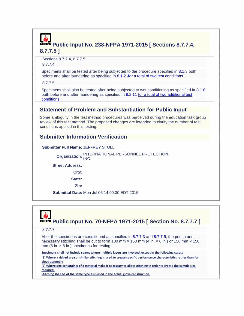
Public Input No. 238-NFPA 1971-2015 [ Sections 8.7.7.4, 8.7.7.5 ]
Sections 8.7.7.4, 8.7.7.5
8.7.7.4
Specimens shall be tested after being subjected to the procedure specified in 8.1.3 both before and after laundering as specified in 8.1.2 .for a total of two test conditions
8.7.7.5
Specimens shall also be tested after being subjected to wet conditioning as specified in 8.1.8 both before and after laundering as specified in 8.2.11 for a total of two additional test conditions.
Statement of Problem and Substantiation for Public Input
Some ambiguity in the test method procedures was perceived during the education task group review of this test method. The proposed changes are intended to clarify the number of test conditions applied in this testing.
Submitter Information Verification
Submitter Full Name: JEFFREY STULL
Organization: INTERNATIONAL PERSONNEL PROTECTION, INC.
Street Address:
City:
State:
Zip:
Submittal Date: Mon Jul 06 14:00:30 EDT 2015
Public Input No. 70-NFPA 1971-2015 [ Section No. 8.7.7.7 ]
8.7.7.7
After the specimens are conditioned as specified in 8.7.7.3 and 8.7.7.5, the pouch and necessary stitching shall be cut to form 100 mm × 150 mm (4 in. × 6 in.) or 150 mm × 150 mm (6 in. × 6 in.) specimens for testing.
Specimens shall not include seams where multiple layers are involved, except in the following cases: (1) Where a ridged area or similar stitching is used to create specific performance characteristics rather than for glove assembly (2) Where size constraints of a material make it necessary to allow stitching in order to create the sample size required. Stitching shall be of the same type as is used in the actual glove construction.
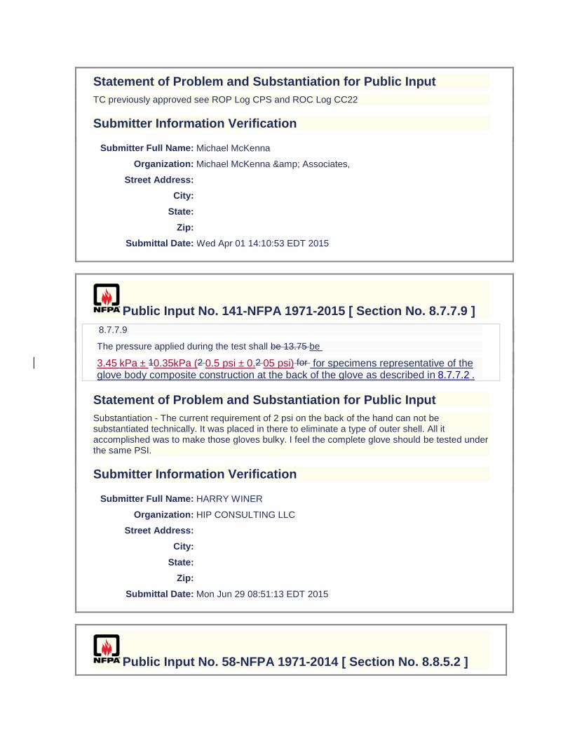
Statement of Problem and Substantiation for Public Input
TC previously approved see ROP Log CPS and ROC Log CC22
Submitter Information Verification
Submitter Full Name: Michael McKenna
Organization: Michael McKenna & Associates,
Street Address:
City:
State:
Zip:
Submittal Date: Wed Apr 01 14:10:53 EDT 2015
Public Input No. 141-NFPA 1971-2015 [ Section No. 8.7.7.9 ]
8.7.7.9
The pressure applied during the test shall be 13.75 be
3.45 kPa ± 10.35kPa (2 0.5 psi ± 0.2 05 psi) for for specimens representative of the glove body composite construction at the back of the glove as described in 8.7.7.2 .
Statement of Problem and Substantiation for Public Input
Substantiation - The current requirement of 2 psi on the back of the hand can not be substantiated technically. It was placed in there to eliminate a type of outer shell. All it accomplished was to make those gloves bulky. I feel the complete glove should be tested under the same PSI.
Submitter Information Verification
Submitter Full Name: HARRY WINER
Organization: HIP CONSULTING LLC
Street Address:
City:
State:
Zip:
Submittal Date: Mon Jun 29 08:51:13 EDT 2015
Public Input No. 58-NFPA 1971-2014 [ Section No. 8.8.5.2 ]

8.8.5.2
The hotplate shall be heated to a temperature of 260°C ± 105°C 5°C (500°F ± 10°F) and shall maintain this temperature throughout the test period.
Statement of Problem and Substantiation for Public Input
Tolerance was incorrect vs Current printed edition
Submitter Information Verification
Submitter Full Name: Jason Allen
Organization: Intertek Testing Services
Street Address:
City:
State:
Zip:
Submittal Date: Tue Jul 01 16:59:30 EDT 2014
Public Input No. 57-NFPA 1971-2014 [ Section No. 8.8.5.3 ]
8.8.5.3
The specimen shall be filled with 4.55 kg /- .25 kg (10 lb) of 10 mm /1 mm (0.39 in.) steel balls. The weight of the steel balls shall be evenly distributed inside the boot. The specimen shall be placed on the plate in the upright position for 20 minutes, + 15/-0 seconds.
Statement of Problem and Substantiation for Public Input
Tolerance is needed for lab to lab consistency
Submitter Information Verification
Submitter Full Name: Jason Allen
Organization: Intertek Testing Services
Street Address:
City:
State:
Zip:
Submittal Date: Tue Jul 01 16:54:04 EDT 2014
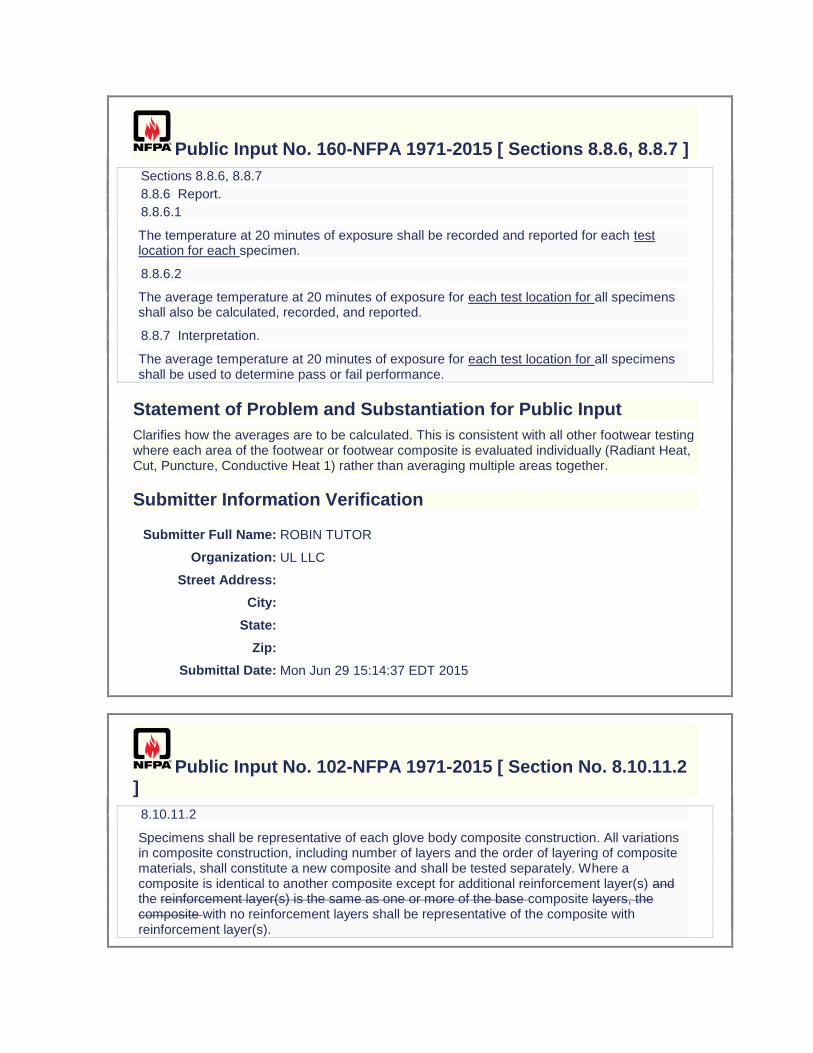
Public Input No. 160-NFPA 1971-2015 [ Sections 8.8.6, 8.8.7 ]
Sections 8.8.6, 8.8.7
8.8.6 Report.
8.8.6.1
The temperature at 20 minutes of exposure shall be recorded and reported for each test location for each specimen.
8.8.6.2
The average temperature at 20 minutes of exposure for each test location for all specimens shall also be calculated, recorded, and reported.
8.8.7 Interpretation.
The average temperature at 20 minutes of exposure for each test location for all specimens shall be used to determine pass or fail performance.
Statement of Problem and Substantiation for Public Input
Clarifies how the averages are to be calculated. This is consistent with all other footwear testing where each area of the footwear or footwear composite is evaluated individually (Radiant Heat, Cut, Puncture, Conductive Heat 1) rather than averaging multiple areas together.
Submitter Information Verification
Submitter Full Name: ROBIN TUTOR
Organization: UL LLC
Street Address:
City:
State:
Zip:
Submittal Date: Mon Jun 29 15:14:37 EDT 2015
Public Input No. 102-NFPA 1971-2015 [ Section No. 8.10.11.2 ]
8.10.11.2
Specimens shall be representative of each glove body composite construction. All variations in composite construction, including number of layers and the order of layering of composite materials, shall constitute a new composite and shall be tested separately. Where a composite is identical to another composite except for additional reinforcement layer(s) and the reinforcement layer(s) is the same as one or more of the base composite layers, the composite with no reinforcement layers shall be representative of the composite with reinforcement layer(s).
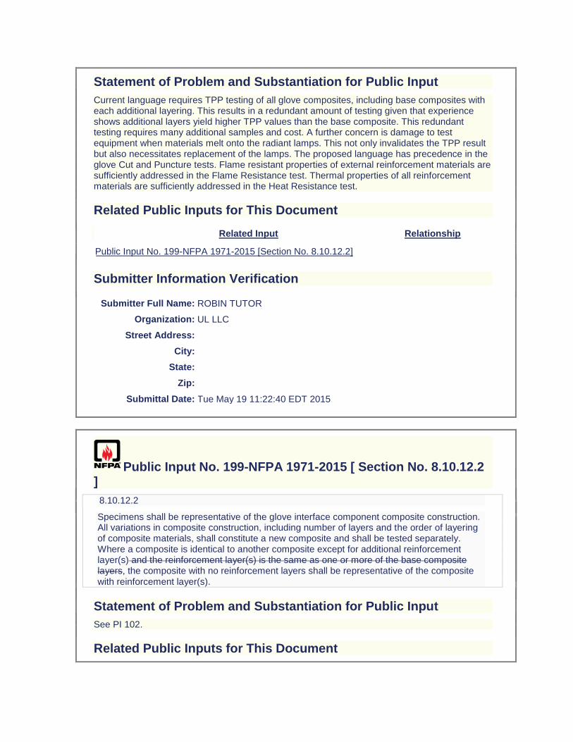
Statement of Problem and Substantiation for Public Input
Current language requires TPP testing of all glove composites, including base composites with each additional layering. This results in a redundant amount of testing given that experience shows additional layers yield higher TPP values than the base composite. This redundant testing requires many additional samples and cost. A further concern is damage to test equipment when materials melt onto the radiant lamps. This not only invalidates the TPP result but also necessitates replacement of the lamps. The proposed language has precedence in the glove Cut and Puncture tests. Flame resistant properties of external reinforcement materials are sufficiently addressed in the Flame Resistance test. Thermal properties of all reinforcement materials are sufficiently addressed in the Heat Resistance test.
Related Public Inputs for This Document
Related Input Relationship
Public Input No. 199-NFPA 1971-2015 [Section No. 8.10.12.2]
Submitter Information Verification
Submitter Full Name: ROBIN TUTOR
Organization: UL LLC
Street Address:
City:
State:
Zip:
Submittal Date: Tue May 19 11:22:40 EDT 2015
Public Input No. 199-NFPA 1971-2015 [ Section No. 8.10.12.2 ]
8.10.12.2
Specimens shall be representative of the glove interface component composite construction. All variations in composite construction, including number of layers and the order of layering of composite materials, shall constitute a new composite and shall be tested separately. Where a composite is identical to another composite except for additional reinforcement layer(s) and the reinforcement layer(s) is the same as one or more of the base composite layers, the composite with no reinforcement layers shall be representative of the composite with reinforcement layer(s).
Statement of Problem and Substantiation for Public Input
See PI 102.
Related Public Inputs for This Document
Related Input Relationship
Public Input No. 102-NFPA 1971-2015 [Section No. 8.10.11.2]
Submitter Information Verification
Submitter Full Name: ROBIN TUTOR
Organization: UL LLC
Street Address:
City:
State:
Zip:
Submittal Date: Thu Jul 02 23:49:35 EDT 2015
Public Input No. 153-NFPA 1971-2015 [ Section No. 8.10.12.3 ]
8.10.12.3
For glove interface component composites, samples for conditioning shall be in the form of a 200 mm × 200 mm (8 in. × 8 in.) pouch as described in 8.1.1115.
Statement of Problem and Substantiation for Public Input
Editorial. Removing redundant dimensional information - pouch dimensions are given in the pouch construction section. Also correction reference for pouch construction section to 8.1.15.
Submitter Information Verification
Submitter Full Name: ROBIN TUTOR
Organization: UL LLC
Street Address:
City:
State:
Zip:
Submittal Date: Mon Jun 29 13:41:20 EDT 2015
Public Input No. 174-NFPA 1971-2015 [ Section No. 8.10.13 ]
8.10.13 Specific Requirements for Testing Helmet Ear Covers and Shrouds.
8.10.13.1
Specimens shall consist of materials from the portion of the ear covers that cover the ear and neck area or from the portion of the shroud that covers the head, face, and neck area. Specimens shall not include seams. Specimens shall not be stitched to hold individual layers together during testing.
8.10.13.2
Samples for conditioning shall include ear cover or shroud material that is a minimum of 175 mm (7 in.) square.
8.10.13.3
Testing shall be performed as described in 8.10.2 through 8.10.7.
Statement of Problem and Substantiation for Public Input
Editorial. The specific requirements for testing helmet ear covers in the TPP test also applies to proximity helmet shrouds.
Submitter Information Verification
Submitter Full Name: ROBIN TUTOR
Organization: UL LLC
Street Address:
City:
State:
Zip:
Submittal Date: Wed Jul 01 15:44:39 EDT 2015
Public Input No. 50-NFPA 1971-2014 [ Sections 8.11.5.2, 8.11.5.3, 8.11.5.4, 8.11.5.5, 8.11.5.6 ]
Sections 8.11.5.2, 8.11.5.3, 8.11.5.4, 8.11.5.5, 8.11.5.6
8.11.5.2
The apparatus shall be calibrated by determining the melting point of a pure material of known melting point. The melting point of the pure material shall be in the range of the melting point of the fiber being tested. The value obtained shall agree within +1°C (33.8°F) of the known value.
8.11.5.3
If the approximate melting point of the specimen is not known before testing, it shall be determined by a trial run.
8.11.5.4
In subsequent determinations immediately following the trial run or initial determination, the stage in each case shall be cooled to approximately 50°C (122°F) below the expected melting point, before the specimen is placed for testing.
8.11.5.5
The specimen shall be placed in a small mound on a cover glass and covered with another cover glass. The two cover glasses shall be pressed together gently but firmly, and placed in the circular depression on the stage. The temperature of the stage shall be raised with some rapidity to within 15°C (59°F) of the expected melting point, and thereafter at a rate of 3°C to 4°C (37.4°F to 39.2°F) per minute. At this rate of temperature rise, a be set at 260°C and a slight pressure shall be applied on the upper glass cover by pressing with a spatula, pick needle, or other instrument so that the complete fiber is in contact with the cover glass.
8.11.5.6
The specimen shall be observed with the aid of a magnifying glass, and the melting point taken as the temperature at which flow of the specimen is observed. At the observed melting point, the temperature shall be read to the nearest degree C.
Statement of Problem and Substantiation for Public Input
Test Method should be a qualitative as a true pass/fail melt test simliar to Heat and Thermal Shrinkage.
Submitter Information Verification
Submitter Full Name: Jason Allen
Organization: Intertek Testing Services
Street Address:
City:
State:
Zip:
Submittal Date: Tue Jul 01 15:37:41 EDT 2014
Public Input No. 51-NFPA 1971-2014 [ Section No. 8.11.6.1 ]
8.11.6.1
The melting point of the sample unit shall be the average of the results obtained from the specimens tested, and shall be recorded and reported to the nearest degree Cshall not melt.
Statement of Problem and Substantiation for Public Input
Test Method shall be qualitative similar to Heat and Thermal Shrinkage
Submitter Information Verification
Submitter Full Name: Jason Allen
Organization: Intertek Testing Services
Street Address:
City:

State:
Zip:
Submittal Date: Tue Jul 01 15:42:22 EDT 2014
Public Input No. 71-NFPA 1971-2015 [ Sections 8.14.1.1, 8.14.1.2 ]
Sections 8.14.1.1, 8.14.1.2
8.14.1.1
This test method shall apply to seams used in protective clothing items, including booties where present, clothing item wristlets, glove wristletsinterface components, glove gauntlets, and hoods.
8.14.1.2
Modifications to this test method for testing clothing item wristlets, glove wristlets, and glove gauntlets interface components shall be as specified in 8.14.7.
Statement of Problem and Substantiation for Public Input
Previously approved by TC - See ROC log 128.
Related Public Inputs for This Document
Related Input Relationship
Public Input No. 72-NFPA 1971-2015 [Section No. 8.14.7]
Submitter Information Verification
Submitter Full Name: Michael McKenna
Organization: Michael McKenna & Associates,
Street Address:
City:
State:
Zip:
Submittal Date: Wed Apr 01 14:15:10 EDT 2015
Public Input No. 72-NFPA 1971-2015 [ Section No. 8.14.7 ]
8.14.7 Specific Requirements for Testing Protective Clothing Item Wristlets, Glove Wristlets, and Glove Gauntlets.Interface Components

8.14.7.1
Specimens for conditioning and testing shall consist of seams taken from the wristlet/clothing item sleeve, or the wristlet/glove body junction, or the gauntletglove interface/glove body junction.
8.14.7.2
Whole gloves shall be permitted to be used for conditioning.
8.14.7.3
Glove specimens shall be conditioned as specified in 8.1.11 prior to testing.
8.14.7.4
Specimen sizes shall be 100 mm × 200 mm (4 in. × 8 in.), with the seam horizontally in the middle of the 100 mm (4 in.) dimension.
8.14.7.5
Evaluation for sewn seam strength in accordance with Section 11.1 of ASTM D 1683, Standard Test Method for Failure in Sewn Seams of Woven Fabrics, shall be used to
determine pass or fail performance.
Statement of Problem and Substantiation for Public Input
Previosly approved by TC - See ROC Log 128.
Related Public Inputs for This Document
Related Input Relationship
Public Input No. 71-NFPA 1971-2015 [Sections 8.14.1.1, 8.14.1.2]
Submitter Information Verification
Submitter Full Name: Michael McKenna
Organization: Michael McKenna & Associates,
Street Address:
City:
State:
Zip:
Submittal Date: Wed Apr 01 14:29:31 EDT 2015
Public Input No. 175-NFPA 1971-2015 [ Section No. 8.17.3.4 ]
8.17.3.4
When testing for the conditions specified in 8.1.3, 8.1.4, and 8.1.7, and the faceshield/goggle component is returned to the conditioning environment before the time out of that conditioning environment exceeds 4 minutes, the faceshield/goggle shall be kept in the

conditioning environment for a minimum of 3 minutes before resumption of testing with that helmet. When the time out of the conditioning environment exceeds 4 minutes, the faceshield/goggle shall be returned to the conditioning environment for a minimum of 3 minutes for each minute or portion of a minute that the faceshield/goggle remained out of the conditioning environment in excess of 4 minutes or for a maximum of 24 hours, whichever is less.
Statement of Problem and Substantiation for Public Input
Editorial.
Submitter Information Verification
Submitter Full Name: ROBIN TUTOR
Organization: UL LLC
Street Address:
City:
State:
Zip:
Submittal Date: Wed Jul 01 15:55:21 EDT 2015
Public Input No. 239-NFPA 1971-2015 [ Section No. 8.20.7.3 ]
8.20.7.3
Glove specimens shall also be tested after wet conditioning as specified in 8.1.8 for a second test condition.
Statement of Problem and Substantiation for Public Input
Some ambiguity in the test method procedures was perceived during the education task group review of this test method. The proposed change is intended to clarify the number of test conditions applied in this testing.
Submitter Information Verification
Submitter Full Name: JEFFREY STULL
Organization: INTERNATIONAL PERSONNEL PROTECTION, INC.
Street Address:
City:
State:
Zip:
Submittal Date: Mon Jul 06 14:05:25 EDT 2015

Public Input No. 73-NFPA 1971-2015 [ Sections 8.21.2.1, 8.21.2.2 ]
Sections 8.21.2.1, 8.21.2.2
8.21.2.1
Glove body and glove interface component other than wristlet material samples shall be conditioned as specified in 8.1.2.
8.21.2.2
Glove wristlet interface components and CBRN barrier material samples shall be conditioned as specified in 8.1.2.
Statement of Problem and Substantiation for Public Input
Terminology matches the remainder of the test method - wording was inadvertently left out of original proposal ROP Log CP50.
Submitter Information Verification
Submitter Full Name: Michael McKenna
Organization: Michael McKenna & Associates,
Street Address:
City:
State:
Zip:
Submittal Date: Wed Apr 01 14:35:44 EDT 2015
Public Input No. 176-NFPA 1971-2015 [ Sections 8.22.3.3, 8.22.3.4 ]
Sections 8.22.3.3, 8.22.3.4
8.22.3.3
The left viewing area test specimens shall include all of the following criteria:
(1) The specimen shall be a square measuring 50 mm × 50 mm (2 in. × 2 in.).
(2) Two edges of the square section shall be parallel within ±2 degrees of the axis of the cylinder or cone in the center of the specimen.
(3) The specimen shall be taken from the left side of the faceshield/goggle component lens and shall, as a minimum, contain that portion of the lens that is directly in front of the pupil of the left eye as defined by positioning the helmet with a faceshield/goggle component deployed according to the HPI as described in 8.1.14 on a facial feature headform as defined in 3.3.43. Goggle samples shall be permitted to be complete goggle
components not attached to the helmet.
8.22.3.4
The right viewing area test specimens shall include all of the following criteria:
(1) The specimen shall be a square measuring 50 mm × 50 mm (2 in. × 2 in.).
(2) Two edges of the square section shall be parallel within ±2 degrees of the axis of the cylinder or cone in the center of the specimen.
(3) The specimen shall be taken from the right side of the faceshield/goggle component lens and shall, as a minimum, contain that portion of the lens that is directly in front of the pupil of the right eye as defined by positioning the helmet with a faceshield/goggle component deployed according to the HPI as described in 8.1.14 on a facial feture feature headform as defined in 3.3.43. Goggle samples shall be permitted to be complete goggle components not attached to the helmet.
Statement of Problem and Substantiation for Public Input
This change allows goggles to be tested independent of the helmet as is already allowed in 8.17 Faceshield/Goggle Component Lens Impact Resistance Test.
Submitter Information Verification
Submitter Full Name: ROBIN TUTOR
Organization: UL LLC
Street Address:
City:
State:
Zip:
Submittal Date: Wed Jul 01 16:09:16 EDT 2015
Public Input No. 166-NFPA 1971-2015 [ Section No. 8.23.2.1 ]
8.23.2.1
Samples for conditioning shall be uniform cylinders of footwear soles and heel material.sole and heel materials
as specified in ISO 4649, Rubber, vulcanized or thermoplastic — Determination of abrasion resistance using a rotating
cylindrical drum device ..
Statement of Problem and Substantiation for Public Input
Clarifying sample instructions.
Submitter Information Verification
Submitter Full Name: ROBIN TUTOR
Organization: UL LLC
Street Address:
City:
State:
Zip:
Submittal Date: Mon Jun 29 17:01:10 EDT 2015
Public Input No. 53-NFPA 1971-2014 [ New Section after 8.24.4.3 ]
TITLE OF NEW CONTENT
Water hardness shall not exceed 25 ppm
Statement of Problem and Substantiation for Public Input
Water hardness significantly effects laundering. This additional information is needed to ensure lab to lab consistency.
Submitter Information Verification
Submitter Full Name: Jason Allen
Organization: Intertek Testing Services
Street Address:
City:
State:
Zip:
Submittal Date: Tue Jul 01 16:22:18 EDT 2014
Public Input No. 109-NFPA 1971-2015 [ New Section after 8.24.9.3 ]
8.24.9.3 Specimens shall be placed on a flat surface so that the face opening of the hood is facing up. A ring or disc of a sufficient height and an outer circumference measuring 54.5 cm /- 0.6 cm (21.5 in. /- 0.25 in) shall be inserted in the face opening so that the hood and the installed ring or disc may be visually inspected for gaps between the hood and the ring or disc outer surface.

Statement of Problem and Substantiation for Public Input
This adds the requirement for measuring the hood face opening that was removed from 6.13.6.1 in the "As Received" condition. The new test method is based on the work discussed by the hood task group.
Related Public Inputs for This Document
Related Input Relationship
Public Input No. 107-NFPA 1971-2015 [Section No. 6.13.6.1]
Public Input No. 110-NFPA 1971-2015 [Section No. 8.24.9.5]
Public Input No. 123-NFPA 1971-2015 [Section No. 7.13.6]
Submitter Information Verification
Submitter Full Name: AMANDA NEWSOM
Organization: UL LLC
Street Address:
City:
State:
Zip:
Submittal Date: Mon Jun 08 13:29:21 EDT 2015
Public Input No. 108-NFPA 1971-2015 [ Section No. 8.24.9.3 ]
8.24.9.3
Specimens shall be donned on a nonconductive test headform specified in Figure 8.6.12.3. The dimensions of the face opening shall be measured as specified in 8.46.4.2. Measurements shall also be made at the back and both sides of the hood from the top of the hood to the basic plane. The location of the basic plane on the hood shall be marked at each location.
Statement of Problem and Substantiation for Public Input
Removing the requirement to measure the face opening diameters based on the work provided by the hood task group.
Related Public Inputs for This Document
Related Input Relationship
Public Input No. 107-NFPA 1971-2015 [Section No. 6.13.6.1]
Public Input No. 123-NFPA 1971-2015 [Section No. 7.13.6]
Submitter Information Verification
Submitter Full Name: AMANDA NEWSOM
Organization: UL LLC
Street Address:
City:
State:
Zip:
Submittal Date: Mon Jun 08 11:25:39 EDT 2015
Public Input No. 110-NFPA 1971-2015 [ Section No. 8.24.9.5 ]
8.24.9.5
After washing, each specimen shall be placed on a flat surface so that the face opening of the hood is facing up. The ring or disc specified in 8.24.9.3 shall be inserted in the face opening so that the hood and the installed ring or disc may be visually inspected for gaps between the hood and the ring or disc outer surface. Specimens shall then be donned on a nonconductive test headform specified in Figure 8.6.12.3. Knit specimens shall be pulled to original dimensions and shall be allowed to relax for 1 minute prior to measurement. The dimensions of the face opening shall be measured as specified in 8.46.4.2 or 8.46.5.7. Measurements shall also be made from the top of the hood to the marks at the back and both sides of the hood.
Statement of Problem and Substantiation for Public Input
This updates the post-test measuring requirement for the face opening based on the hood task group findings.
Related Public Inputs for This Document
Related Input Relationship
Public Input No. 107-NFPA 1971-2015 [Section No. 6.13.6.1]
Public Input No. 109-NFPA 1971-2015 [New Section after 8.24.9.3]
Public Input No. 111-NFPA 1971-2015 [Section No. 8.24.9.6]
Public Input No. 112-NFPA 1971-2015 [Section No. 8.24.9.7]
Public Input No. 123-NFPA 1971-2015 [Section No. 7.13.6]
Submitter Information Verification
Submitter Full Name: AMANDA NEWSOM
Organization: UL LLC
Street Address:
City:
State:
Zip:
Submittal Date: Mon Jun 08 14:07:08 EDT 2015
Public Input No. 111-NFPA 1971-2015 [ Section No. 8.24.9.6 ]
8.24.9.6
Each Observations of gaps between the hood face opening dimension and the ring or disc before and after laundering shall be recorded and reported.
Statement of Problem and Substantiation for Public Input
This updates the post-test recording and reporting requirements for the face opening based on the hood task group findings.
Related Public Inputs for This Document
Related Input Relationship
Public Input No. 107-NFPA 1971-2015 [Section No. 6.13.6.1]
Public Input No. 110-NFPA 1971-2015 [Section No. 8.24.9.5]
Public Input No. 112-NFPA 1971-2015 [Section No. 8.24.9.7]
Public Input No. 123-NFPA 1971-2015 [Section No. 7.13.6]
Submitter Information Verification
Submitter Full Name: AMANDA NEWSOM
Organization: UL LLC
Street Address:
City:
State:
Zip:
Submittal Date: Mon Jun 08 14:30:07 EDT 2015
Public Input No. 112-NFPA 1971-2015 [ Section No. 8.24.9.7 ]
8.24.9.7
The percent difference of the hood face opening dimensions before and after laundering shall be determined. The average difference of all hood face opening dimensions shall be calculated and reported.
Statement of Problem and Substantiation for Public Input
This updates the post-test recording and reporting requirement for the face opening based on the hood task group findings.
Related Public Inputs for This Document
Related Input Relationship
Public Input No. 107-NFPA 1971-2015 [Section No. 6.13.6.1]
Public Input No. 110-NFPA 1971-2015 [Section No. 8.24.9.5]
Public Input No. 111-NFPA 1971-2015 [Section No. 8.24.9.6]
Public Input No. 114-NFPA 1971-2015 [Section No. 8.24.9.10]
Public Input No. 115-NFPA 1971-2015 [Section No. 8.24.9.12]
Public Input No. 116-NFPA 1971-2015 [Section No. 8.24.9.14]
Public Input No. 123-NFPA 1971-2015 [Section No. 7.13.6]
Submitter Information Verification
Submitter Full Name: AMANDA NEWSOM
Organization: UL LLC
Street Address:
City:
State:
Zip:
Submittal Date: Mon Jun 08 14:35:12 EDT 2015
Public Input No. 11-NFPA 1971-2013 [ Sections 8.24.9.7, 8.24.9.8, 8.24.9.9, 8.24.9.10, 8.24.9.11... ]
Sections 8.24.9.7, 8.24.9.8, 8.24.9.9, 8.24.9.10, 8.24.9.11, 8.24.9.12, 8.24.9.13, 8.24.9.14
8.24.9.9
8.24.9.7
The percent difference of the hood face opening dimensions before and after laundering shall be determined. The average difference of all hood face opening dimensions shall be calculated and reported.
8.24.9.8

Pass or fail performance shall be based on failure in any one dimension for distances between the top of the hood and the marks along the basic plane, and on the average difference of the hood face opening dimensions.
Each of the three dimensions from the top of the hood to the marks along the basic plane before and after laundering shall be recorded and reported.
8.24.9.
10
8 The percent shrinkage of each hood face opening dimension shall be individually
calculated, recorded, and reported.
8.24.9.
11
9 The percent shrinkage of each of the three dimensions from the top of the hood to the
marks along the basic plane shall be individually calculated, recorded, and reported.
8.24.9.
12
10*The average percent shrinkage of all hood face opening dimensions for
each specimen
all specimens shall be calculated, recorded, and reported.
8.24.9.
13
11*The average percent shrinkage of the three dimensions from the top of the hood to the
marks along the basic plane for
each specimen
all specimens shall be calculated, recorded, and reported.
8.24.9.
14
12Pass or fail performance shall be based separately on the average percent shrinkage of
the hood face opening dimensions and the average percent shrinkage of the three dimensions from the top of the hood to the marks along the basic plane for
each specimen. One or more hood specimens failing this test shall constitute failing performance
all specimens.
Additional Proposed Changes
File Name Description Approved
Proposed_TIA_1092_1971_.docx Balloted TIA
Statement of Problem and Substantiation for Public Input
Note: This Public Input originates from Tentative Interim Amendment 1971-13-2 (TIA 1092) issued by the Standards Council on March 7, 2013. 1. The ASTM 2412 Standard needs to be
updated to the current edition. 2, 3, and 14. The specific requirements for glove labels, which included type of fiber or material type, were inadvertently included in the generic list of requirements for labels on all ensemble elements. Since the majority of fabrics and materials used in construction of many of the ensemble elements contain multiple fibers and numerous blends, even attempting to include this level of detail on every product label would cause mass confusion. The issue becomes even more exacerbated by the minimum font sizes required on label text and by a garment specific label requirement, also included in the generic list, which mandates explicit component names as per the certification listing. This change provides the generic requirements for all labels, and then separates the specific ensemble element label requirements into subsets to avoid any interpretation issues. 4. The NFPA 1971 proposal (1971-46, Log CP-50) neglected to include the test method reference to Section 8.4 as well as the requirement for char length. NFPA 1971, 2013 edition references several flame resistance tests. It is important the standard references the correct flame resistance test and section number to insure the correct testing procedures are being followed. It was also the technical committee’s intent, based on historical data, to have the glove interface component evaluated for char length in addition to afterflame. 5. The NFPA 1971 proposal (1971-46, Log CP-50) neglected to include the test method reference to Section 8.4 as well as the requirement for char length. NFPA 1971, 2013 edition references several flame resistance tests. It is important the standard references the correct flame resistance test and section number to insure the correct testing procedures are being followed. It was also the technical committee’s intent, based on historical data, to have the glove extension component evaluated for char length in addition to afterflame. 6. This change brings this requirement in line with EN ISO 20345:2011. 7. The current laundering method described in Section 8.1.11 only accounts for water levels when laundering garments and CBRN Materials. The 2013 edition of NFPA 1971 now requires gloves and glove pouches to be laundered using Section 8.1.11 as a precondition. However a table for gloves and glove pouch water levels were not included. The water levels for the glove and glove pouch wash cycle needs to be specified in NFPA 1971, 2013 edition in order to allow for the front load wash machines to be properly programmed at the testing laboratories. The highest water levels currently in the standard were chosen to account for usage of both 35 lb and 50 lb capacity front-loading machines. The higher levels will also accommodate a full load of gloves/glove pouches and eliminate any risk associated with residual detergent. 8, 9, 15 and 16. Some changes made to the way the measurement of hood shrinkage were specified in cleaning shrinkage as part of the NFPA 1971-2013 revision would prevent any hood from being certified to the new requirements. There was also an inconsistency between how hood shrinkage was evaluated for both thermal and cleaning shrinkage for the interpretation of test results that would lead to inconsistent determinations of compliance among testing laboratories. The proposed changes using the same approach established in the 2007 edition of NFPA 1971 for applying cleaning shrinkage criteria while clarifications have been made for interpretation of permitted shrinkage in both cleaning and thermal shrinkage test methods. 10. NFPA 1971, 2013 edition has sections for glove pouch construction, sections 8.1.15 and 8.1.16. Section 8.27.8.2, section for Liquid Penetration Resistance, should reference section 8.1.16 for moisture barrier testing. 11. NFPA 1971, 2013 edition has sections for glove pouch construction, sections 8.1.15 and 8.1.16. Section 8.28.8.2, section for Viral Penetration Resistance, should reference section 8.1.16 for moisture barrier testing. 12. The ISO 13287 standard does not provide criteria for the evaluation of systematic increase or decrease of values. Also, the current calibration language is not clear. 13. The test apparatus will be maxed out if the test subject uses their arm’s range of motion to perform this test. In order to achieve more accurate results it is important the test subject use their wrist’s range of motion to perform this test. Emergency Nature: This TIA seeks to correct errors and omissions that were overlooked during the Fall 2013 revision cycle process of NFPA 1971. Additionally, some parts of this TIA correct circumstances in which the standard could adversely impact a method or product that was inadvertently overlooked in the total revision process.
Submitter Information Verification
Submitter Full Name:
TC on FAE-SPF
Organization: TC on Structural and Proximity Fire Fighting Protective Clothing and Equipment
Street Address:
City:
State:
Zip:
Submittal Date: Fri Aug 09 14:40:49 EDT 2013
Public Input No. 113-NFPA 1971-2015 [ Section No. 8.24.9.8 ]
8.24.9.8
Pass or fail performance shall be based on failure in any one dimension for distances between the top of the hood and the marks along the basic plane, and on the average difference of the hood face opening dimensions.
Statement of Problem and Substantiation for Public Input
This paragraph is redundant to 8.24.9.14 and is being removed based on the new face opening measurement procedure being suggested by the hood task group.
Related Public Inputs for This Document
Related Input Relationship
Public Input No. 107-NFPA 1971-2015 [Section No. 6.13.6.1]
Submitter Information Verification
Submitter Full Name: AMANDA NEWSOM
Organization: UL LLC
Street Address:
City:
State:
Zip:
Submittal Date: Mon Jun 08 14:36:55 EDT 2015
Public Input No. 114-NFPA 1971-2015 [ Section No. 8.24.9.10 ]
8.24.9.10
The percent shrinkage of each hood face opening shall be calculated, recorded, and reported.
Statement of Problem and Substantiation for Public Input
This updates the recording and reporting requirement for the face opening based on the hood task group findings.
Related Public Inputs for This Document
Related Input Relationship
Public Input No. 107-NFPA 1971-2015 [Section No. 6.13.6.1]
Public Input No. 112-NFPA 1971-2015 [Section No. 8.24.9.7]
Public Input No. 115-NFPA 1971-2015 [Section No. 8.24.9.12]
Public Input No. 116-NFPA 1971-2015 [Section No. 8.24.9.14]
Public Input No. 123-NFPA 1971-2015 [Section No. 7.13.6]
Submitter Information Verification
Submitter Full Name: AMANDA NEWSOM
Organization: UL LLC
Street Address:
City:
State:
Zip:
Submittal Date: Mon Jun 08 14:39:40 EDT 2015
Public Input No. 115-NFPA 1971-2015 [ Section No. 8.24.9.12 ]
8.24.9.12
The average percent shrinkage of all hood face opening dimensions for each specimen shall be calculated, recorded, and reported.
Statement of Problem and Substantiation for Public Input
This updates the recording and reporting requirement for the face opening based on the hood task group findings.
Related Public Inputs for This Document
Related Input Relationship
Public Input No. 107-NFPA 1971-2015 [Section No. 6.13.6.1]
Public Input No. 112-NFPA 1971-2015 [Section No. 8.24.9.7]
Public Input No. 114-NFPA 1971-2015 [Section No. 8.24.9.10]
Public Input No. 116-NFPA 1971-2015 [Section No. 8.24.9.14]
Public Input No. 123-NFPA 1971-2015 [Section No. 7.13.6]
Submitter Information Verification
Submitter Full Name: AMANDA NEWSOM
Organization: UL LLC
Street Address:
City:
State:
Zip:
Submittal Date: Mon Jun 08 14:41:00 EDT 2015
Public Input No. 116-NFPA 1971-2015 [ Section No. 8.24.9.14 ]
8.24.9.14
Pass or fail performance shall be based on the average percent shrinkage of the hood face opening dimensions and the average percent shrinkage of the three dimensions from the top of the hood to the marks along the basic plane for each specimen
, and on any observations of gaps between the hood face opening and the ring or disc . One or more hood specimens failing this test shall constitute failing performance.
Statement of Problem and Substantiation for Public Input
This updates the pass/fail criteria for the hood face opening based on the task group findings.
Related Public Inputs for This Document
Related Input Relationship
Public Input No. 107-NFPA 1971-2015 [Section No. 6.13.6.1]
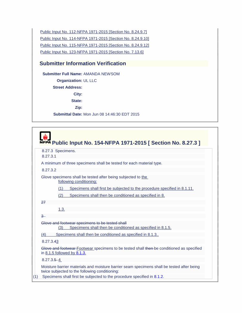
Public Input No. 112-NFPA 1971-2015 [Section No. 8.24.9.7]
Public Input No. 114-NFPA 1971-2015 [Section No. 8.24.9.10]
Public Input No. 115-NFPA 1971-2015 [Section No. 8.24.9.12]
Public Input No. 123-NFPA 1971-2015 [Section No. 7.13.6]
Submitter Information Verification
Submitter Full Name: AMANDA NEWSOM
Organization: UL LLC
Street Address:
City:
State:
Zip:
Submittal Date: Mon Jun 08 14:46:30 EDT 2015
Public Input No. 154-NFPA 1971-2015 [ Section No. 8.27.3 ]
8.27.3 Specimens.
8.27.3.1
A minimum of three specimens shall be tested for each material type.
8.27.3.2
Glove specimens shall be tested after being subjected to the following conditioning:
(1) Specimens shall first be subjected to the procedure specified in 8.1.11.
(2) Specimens shall then be conditioned as specified in 8.
27
1.3.
3
Glove and footwear specimens to be tested shall (3) Specimens shall then be conditioned as specified in 8.1.5.
(4) Specimens shall then be conditioned as specified in 8.1.3..
8.27.3.43
Glove and footwear Footwear specimens to be tested shall then be conditioned as specified in 8.1.5 followed by 8.1.3.
8.27.3.5 4
Moisture barrier materials and moisture barrier seam specimens shall be tested after being twice subjected to the following conditioning:
(1) Specimens shall first be subjected to the procedure specified in 8.1.2.
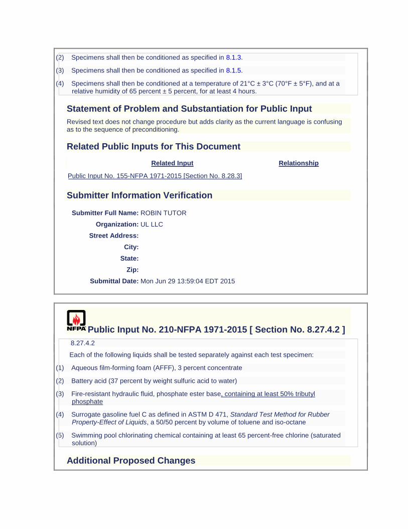
(2) Specimens shall then be conditioned as specified in 8.1.3.
(3) Specimens shall then be conditioned as specified in 8.1.5.
(4) Specimens shall then be conditioned at a temperature of 21°C ± 3°C (70°F ± 5°F), and at a relative humidity of 65 percent ± 5 percent, for at least 4 hours.
Statement of Problem and Substantiation for Public Input
Revised text does not change procedure but adds clarity as the current language is confusing as to the sequence of preconditioning.
Related Public Inputs for This Document
Related Input Relationship
Public Input No. 155-NFPA 1971-2015 [Section No. 8.28.3]
Submitter Information Verification
Submitter Full Name: ROBIN TUTOR
Organization: UL LLC
Street Address:
City:
State:
Zip:
Submittal Date: Mon Jun 29 13:59:04 EDT 2015
Public Input No. 210-NFPA 1971-2015 [ Section No. 8.27.4.2 ]
8.27.4.2
Each of the following liquids shall be tested separately against each test specimen:
(1) Aqueous film-forming foam (AFFF), 3 percent concentrate
(2) Battery acid (37 percent by weight sulfuric acid to water)
(3) Fire-resistant hydraulic fluid, phosphate ester base, containing at least 50% tributyl phosphate
(4) Surrogate gasoline fuel C as defined in ASTM D 471, Standard Test Method for Rubber Property-Effect of Liquids, a 50/50 percent by volume of toluene and iso-octane
(5) Swimming pool chlorinating chemical containing at least 65 percent-free chlorine (saturated solution)
Additional Proposed Changes
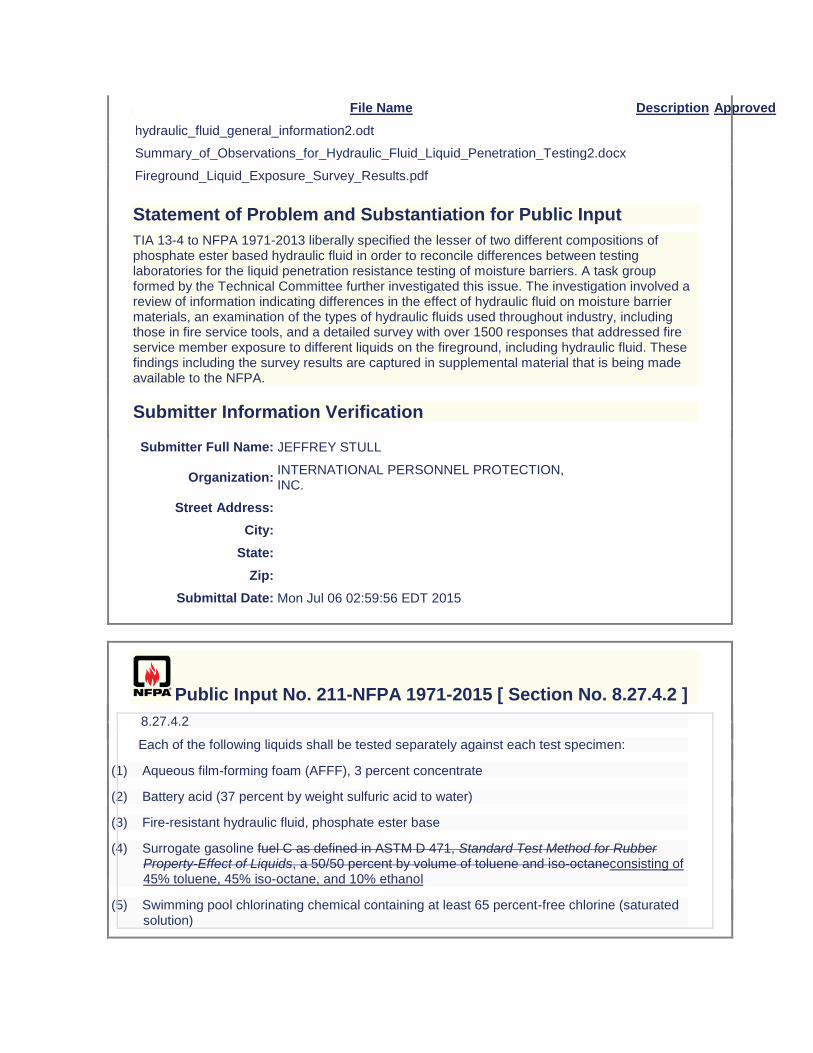
File Name Description Approved
hydraulic_fluid_general_information2.odt
Summary_of_Observations_for_Hydraulic_Fluid_Liquid_Penetration_Testing2.docx
Fireground_Liquid_Exposure_Survey_Results.pdf
Statement of Problem and Substantiation for Public Input
TIA 13-4 to NFPA 1971-2013 liberally specified the lesser of two different compositions of phosphate ester based hydraulic fluid in order to reconcile differences between testing laboratories for the liquid penetration resistance testing of moisture barriers. A task group formed by the Technical Committee further investigated this issue. The investigation involved a review of information indicating differences in the effect of hydraulic fluid on moisture barrier materials, an examination of the types of hydraulic fluids used throughout industry, including those in fire service tools, and a detailed survey with over 1500 responses that addressed fire service member exposure to different liquids on the fireground, including hydraulic fluid. These findings including the survey results are captured in supplemental material that is being made available to the NFPA.
Submitter Information Verification
Submitter Full Name: JEFFREY STULL
Organization: INTERNATIONAL PERSONNEL PROTECTION, INC.
Street Address:
City:
State:
Zip:
Submittal Date: Mon Jul 06 02:59:56 EDT 2015
Public Input No. 211-NFPA 1971-2015 [ Section No. 8.27.4.2 ]
8.27.4.2
Each of the following liquids shall be tested separately against each test specimen:
(1) Aqueous film-forming foam (AFFF), 3 percent concentrate
(2) Battery acid (37 percent by weight sulfuric acid to water)
(3) Fire-resistant hydraulic fluid, phosphate ester base
(4) Surrogate gasoline fuel C as defined in ASTM D 471, Standard Test Method for Rubber Property-Effect of Liquids, a 50/50 percent by volume of toluene and iso-octaneconsisting of 45% toluene, 45% iso-octane, and 10% ethanol
(5) Swimming pool chlorinating chemical containing at least 65 percent-free chlorine (saturated solution)
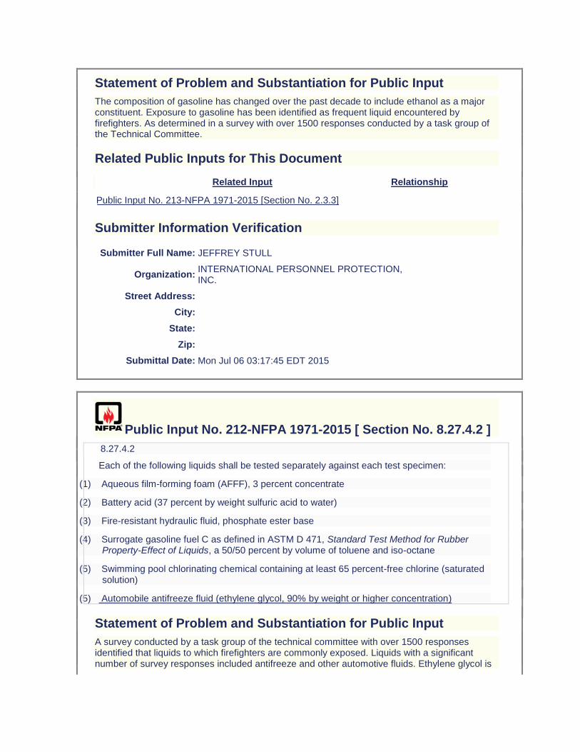
Statement of Problem and Substantiation for Public Input
The composition of gasoline has changed over the past decade to include ethanol as a major constituent. Exposure to gasoline has been identified as frequent liquid encountered by firefighters. As determined in a survey with over 1500 responses conducted by a task group of the Technical Committee.
Related Public Inputs for This Document
Related Input Relationship
Public Input No. 213-NFPA 1971-2015 [Section No. 2.3.3]
Submitter Information Verification
Submitter Full Name: JEFFREY STULL
Organization: INTERNATIONAL PERSONNEL PROTECTION, INC.
Street Address:
City:
State:
Zip:
Submittal Date: Mon Jul 06 03:17:45 EDT 2015
Public Input No. 212-NFPA 1971-2015 [ Section No. 8.27.4.2 ]
8.27.4.2
Each of the following liquids shall be tested separately against each test specimen:
(1) Aqueous film-forming foam (AFFF), 3 percent concentrate
(2) Battery acid (37 percent by weight sulfuric acid to water)
(3) Fire-resistant hydraulic fluid, phosphate ester base
(4) Surrogate gasoline fuel C as defined in ASTM D 471, Standard Test Method for Rubber Property-Effect of Liquids, a 50/50 percent by volume of toluene and iso-octane
(5) Swimming pool chlorinating chemical containing at least 65 percent-free chlorine (saturated solution)
(5) Automobile antifreeze fluid (ethylene glycol, 90% by weight or higher concentration)
Statement of Problem and Substantiation for Public Input
A survey conducted by a task group of the technical committee with over 1500 responses identified that liquids to which firefighters are commonly exposed. Liquids with a significant number of survey responses included antifreeze and other automotive fluids. Ethylene glycol is
the most common fluid of this type. The suggested concentration of ethylene glycol is also a common percentage composition for antifreeze.
Submitter Information Verification
Submitter Full Name: JEFFREY STULL
Organization: INTERNATIONAL PERSONNEL PROTECTION, INC.
Street Address:
City:
State:
Zip:
Submittal Date: Mon Jul 06 03:32:56 EDT 2015
Public Input No. 12-NFPA 1971-2013 [ Section No. 8.27.8.2 ]
8.27.8.2
Samples for conditioning shall be in the form of a pouch as described in 8.1.1516.
Additional Proposed Changes
File Name Description Approved
Proposed_TIA_1092_1971_.docx Balloted TIA
Statement of Problem and Substantiation for Public Input
Note: This Public Input originates from Tentative Interim Amendment 1971-13-2 (TIA 1092) issued by the Standards Council on March 7, 2013. 1. The ASTM 2412 Standard needs to be updated to the current edition. 2, 3, and 14. The specific requirements for glove labels, which included type of fiber or material type, were inadvertently included in the generic list of requirements for labels on all ensemble elements. Since the majority of fabrics and materials used in construction of many of the ensemble elements contain multiple fibers and numerous blends, even attempting to include this level of detail on every product label would cause mass confusion. The issue becomes even more exacerbated by the minimum font sizes required on label text and by a garment specific label requirement, also included in the generic list, which mandates explicit component names as per the certification listing. This change provides the generic requirements for all labels, and then separates the specific ensemble element label requirements into subsets to avoid any interpretation issues. 4. The NFPA 1971 proposal (1971-46, Log CP-50) neglected to include the test method reference to Section 8.4 as well as the requirement for char length. NFPA 1971, 2013 edition references several flame resistance tests. It is important the standard references the correct flame resistance test and section number to insure the correct testing procedures are being followed. It was also the technical committee’s intent, based on historical data, to have the glove interface component evaluated for char length in addition to afterflame. 5. The NFPA 1971 proposal (1971-46, Log CP-50) neglected to include the test method reference to Section 8.4 as well as the requirement for char length. NFPA 1971, 2013 edition references several flame resistance tests. It is important the standard references the correct flame resistance test and section number to insure the
correct testing procedures are being followed. It was also the technical committee’s intent, based on historical data, to have the glove extension component evaluated for char length in addition to afterflame. 6. This change brings this requirement in line with EN ISO 20345:2011. 7. The current laundering method described in Section 8.1.11 only accounts for water levels when laundering garments and CBRN Materials. The 2013 edition of NFPA 1971 now requires gloves and glove pouches to be laundered using Section 8.1.11 as a precondition. However a table for gloves and glove pouch water levels were not included. The water levels for the glove and glove pouch wash cycle needs to be specified in NFPA 1971, 2013 edition in order to allow for the front load wash machines to be properly programmed at the testing laboratories. The highest water levels currently in the standard were chosen to account for usage of both 35 lb and 50 lb capacity front-loading machines. The higher levels will also accommodate a full load of gloves/glove pouches and eliminate any risk associated with residual detergent. 8, 9, 15 and 16. Some changes made to the way the measurement of hood shrinkage were specified in cleaning shrinkage as part of the NFPA 1971-2013 revision would prevent any hood from being certified to the new requirements. There was also an inconsistency between how hood shrinkage was evaluated for both thermal and cleaning shrinkage for the interpretation of test results that would lead to inconsistent determinations of compliance among testing laboratories. The proposed changes using the same approach established in the 2007 edition of NFPA 1971 for applying cleaning shrinkage criteria while clarifications have been made for interpretation of permitted shrinkage in both cleaning and thermal shrinkage test methods. 10. NFPA 1971, 2013 edition has sections for glove pouch construction, sections 8.1.15 and 8.1.16. Section 8.27.8.2, section for Liquid Penetration Resistance, should reference section 8.1.16 for moisture barrier testing. 11. NFPA 1971, 2013 edition has sections for glove pouch construction, sections 8.1.15 and 8.1.16. Section 8.28.8.2, section for Viral Penetration Resistance, should reference section 8.1.16 for moisture barrier testing. 12. The ISO 13287 standard does not provide criteria for the evaluation of systematic increase or decrease of values. Also, the current calibration language is not clear. 13. The test apparatus will be maxed out if the test subject uses their arm’s range of motion to perform this test. In order to achieve more accurate results it is important the test subject use their wrist’s range of motion to perform this test. Emergency Nature: This TIA seeks to correct errors and omissions that were overlooked during the Fall 2013 revision cycle process of NFPA 1971. Additionally, some parts of this TIA correct circumstances in which the standard could adversely impact a method or product that was inadvertently overlooked in the total revision process.
Submitter Information Verification
Submitter Full Name:
TC on FAE-SPF
Organization: TC on Structural and Proximity Fire Fighting Protective Clothing and Equipment
Street Address:
City:
State:
Zip:
Submittal Date: Fri Aug 09 14:43:28 EDT 2013
Public Input No. 155-NFPA 1971-2015 [ Section No. 8.28.3 ]

8.28.3 Specimens.
8.28.3.1
A minimum of three specimens shall be tested for each material type.
8.28.3.2
Glove specimens shall be tested after being subjected to the following conditioning:
(1) Specimens shall first be subjected to the procedure specified in 8.1.11.
(2) Specimens shall then be conditioned as specified in 8.
28
1.3.
3
Glove and footwear specimens to be tested shall (3) Specimens shall then be conditioned as specified in 8.1.5.
(4) Specimens shall then be conditioned as specified in 8.1.3..
8.28.3.43
Glove and footwear Footwear specimens to be tested shall then be conditioned as specified in 8.1.5 followed by 8.1.3.
8.28.3.5 4
Moisture barrier material and moisture barrier seam specimens shall be tested after being twice subjected to the following conditioning:
(1) Specimens shall first be subjected to the procedure specified in 8.1.2.
(2) Specimens shall then be conditioned as specified in 8.1.3.
(3) Specimens shall then be conditioned as specified in 8.1.5.
(4) Specimens shall then be conditioned at a temperature of 21°C ± 3°C (70°F ± 5°F), and at a relative humidity of 65 percent ± 5 percent for at least 4 hours.
Statement of Problem and Substantiation for Public Input
Adds clarity - see PI 154.
Related Public Inputs for This Document
Related Input Relationship
Public Input No. 154-NFPA 1971-2015 [Section No. 8.27.3] 154 Liquid Pen, 155 Viral Pen
Submitter Information Verification
Submitter Full Name: ROBIN TUTOR
Organization: UL LLC
Street Address:
City:
State:
Zip:
Submittal Date: Mon Jun 29 14:04:18 EDT 2015
Public Input No. 13-NFPA 1971-2013 [ Section No. 8.28.8.2 ]
8.28.8.2
Samples for conditioning shall be in the form of a pouch as described in 8.1.1516.
Additional Proposed Changes
File Name Description Approved
Proposed_TIA_1092_1971_.docx Balloted TIA
Statement of Problem and Substantiation for Public Input
Note: This Public Input originates from Tentative Interim Amendment 1971-13-2 (TIA 1092) issued by the Standards Council on March 7, 2013. 1. The ASTM 2412 Standard needs to be updated to the current edition. 2, 3, and 14. The specific requirements for glove labels, which included type of fiber or material type, were inadvertently included in the generic list of requirements for labels on all ensemble elements. Since the majority of fabrics and materials used in construction of many of the ensemble elements contain multiple fibers and numerous blends, even attempting to include this level of detail on every product label would cause mass confusion. The issue becomes even more exacerbated by the minimum font sizes required on label text and by a garment specific label requirement, also included in the generic list, which mandates explicit component names as per the certification listing. This change provides the generic requirements for all labels, and then separates the specific ensemble element label requirements into subsets to avoid any interpretation issues. 4. The NFPA 1971 proposal (1971-46, Log CP-50) neglected to include the test method reference to Section 8.4 as well as the requirement for char length. NFPA 1971, 2013 edition references several flame resistance tests. It is important the standard references the correct flame resistance test and section number to insure the correct testing procedures are being followed. It was also the technical committee’s intent, based on historical data, to have the glove interface component evaluated for char length in addition to afterflame. 5. The NFPA 1971 proposal (1971-46, Log CP-50) neglected to include the test method reference to Section 8.4 as well as the requirement for char length. NFPA 1971, 2013 edition references several flame resistance tests. It is important the standard references the correct flame resistance test and section number to insure the correct testing procedures are being followed. It was also the technical committee’s intent, based on historical data, to have the glove extension component evaluated for char length in addition to afterflame. 6. This change brings this requirement in line with EN ISO 20345:2011. 7. The current laundering method described in Section 8.1.11 only accounts for water levels when laundering garments and CBRN Materials. The 2013 edition of NFPA 1971 now requires gloves and glove pouches to be laundered using Section 8.1.11 as a precondition. However a table for gloves and glove pouch water levels were not included. The water levels for the glove and glove pouch wash cycle needs to be specified in NFPA 1971, 2013 edition in order to allow for the front load wash machines to be properly programmed at the testing laboratories. The highest water levels currently in the standard were chosen to account for usage of both 35 lb
and 50 lb capacity front-loading machines. The higher levels will also accommodate a full load of gloves/glove pouches and eliminate any risk associated with residual detergent. 8, 9, 15 and 16. Some changes made to the way the measurement of hood shrinkage were specified in cleaning shrinkage as part of the NFPA 1971-2013 revision would prevent any hood from being certified to the new requirements. There was also an inconsistency between how hood shrinkage was evaluated for both thermal and cleaning shrinkage for the interpretation of test results that would lead to inconsistent determinations of compliance among testing laboratories. The proposed changes using the same approach established in the 2007 edition of NFPA 1971 for applying cleaning shrinkage criteria while clarifications have been made for interpretation of permitted shrinkage in both cleaning and thermal shrinkage test methods. 10. NFPA 1971, 2013 edition has sections for glove pouch construction, sections 8.1.15 and 8.1.16. Section 8.27.8.2, section for Liquid Penetration Resistance, should reference section 8.1.16 for moisture barrier testing. 11. NFPA 1971, 2013 edition has sections for glove pouch construction, sections 8.1.15 and 8.1.16. Section 8.28.8.2, section for Viral Penetration Resistance, should reference section 8.1.16 for moisture barrier testing. 12. The ISO 13287 standard does not provide criteria for the evaluation of systematic increase or decrease of values. Also, the current calibration language is not clear. 13. The test apparatus will be maxed out if the test subject uses their arm’s range of motion to perform this test. In order to achieve more accurate results it is important the test subject use their wrist’s range of motion to perform this test. Emergency Nature: This TIA seeks to correct errors and omissions that were overlooked during the Fall 2013 revision cycle process of NFPA 1971. Additionally, some parts of this TIA correct circumstances in which the standard could adversely impact a method or product that was inadvertently overlooked in the total revision process.
Submitter Information Verification
Submitter Full Name:
TC on FAE-SPF
Organization: TC on Structural and Proximity Fire Fighting Protective Clothing and Equipment
Street Address:
City:
State:
Zip:
Submittal Date: Fri Aug 09 14:45:45 EDT 2013
Public Input No. 241-NFPA 1971-2015 [ Section No. 8.30.5.1.2 ]
8.30.5.1.2
The dielectric test plane specified in Figure 8.30.5.1.2 shall be marked as a line on the shell of the helmet. The dielectric test plane shall be the plane that passes through the point located 85 mm (3 in.) above the basic plane, where the basic plane and the midsagittal plane intersect at the front of the headform and the point located 60 mm (2 in.) above the basic plane, where the basic plane and the midsagittal plane intersect at the rear of the headform.
Figure 8.30.5.1.2 Test Setup.
Statement of Problem and Substantiation for Public Input
Some ambiguity in the test method procedures was perceived during the education task group review of this test method. The proposed change is intended to clarify having the use of a dielectric line when a dielectric plane is used in the language.
Submitter Information Verification
Submitter Full Name: JEFFREY STULL
Organization: INTERNATIONAL PERSONNEL PROTECTION, INC.
Street Address:
City:
State:
Zip:
Submittal Date: Mon Jul 06 14:14:57 EDT 2015
Public Input No. 161-NFPA 1971-2015 [ Sections 8.31.3, 8.31.4 ]
Sections 8.31.3, 8.31.4
8.31.3 Specimens.
A minimum of three footwear elements in men's size 9 shall be tested.
8.31.4 Procedure.
Sample footwear Specimens shall be tested to 14,000 V (rms) in accordance with Section 9 of ASTM F 2412, Standard Test Method for Foot Protection. The electrode inside the boot shall be conductive metal shot, with the following modification:
(1) Specimens shall be tested to 14,000 V (rms).
Statement of Problem and Substantiation for Public Input
Clarify method since the current version of ASTM F2412 is 18,000 V rather than 14,000V. Specify shoe size to be consistent with ASTM F2412. Remove redundant wording.
Submitter Information Verification
Submitter Full Name: ROBIN TUTOR
Organization: UL LLC
Street Address:

City:
State:
Zip:
Submittal Date: Mon Jun 29 15:41:20 EDT 2015
Public Input No. 252-NFPA 1971-2015 [ Section No. 8.33 ]
8.33* Total Heat Loss (THL) Test.
8.33.1 Application.
8.33.1.1
This test method shall apply to structural fire fighting protective garment element and particulate barrier protective hood interface component composites.
8.33.1.2
Modifications to this test method for testing particulate barrier protective hood interface component components shall be as specified in 8.33.8.
8.33.2 Samples.
Samples shall be conditioned at a temperature of 25°C ± 7°C (77°F ± 13°F), and a relative humidity of 65 percent ± 5 percent, for at least 4 hours.
8.33.2.1
The minimum sample size shall be 51 cm × 51 cm (20 in. × 20 in.).
8.33.3 Specimens.
8.33.3.1
Total heat loss testing shall be conducted on at least three specimens.
8.33.3.2
Specimens shall consist of all layers in the structural fire fighting protective garment or hood composite, arranged in the order and orientation as worn.
8.33.4 Apparatus.
The test apparatus shall be as specified in ASTM F 1868, Standard Test Method for Thermal and Evaporative Resistance of Clothing Materials Using a Sweating Hot Plate.
8.33.4.1
The dimensions for the sweating guarded hot plate shall be a 25.4 cm (10 in.) test plate with a 12.7 cm (5 in.) guard surrounding the test plate.
8.33.5* Procedure.
Testing shall be conducted in accordance with ASTM F 1868, Standard Test Method for Thermal and Evaporative Resistance of Clothing Materials Using a Sweating Hot Plate, using Part C, with the following modifications:
(1) The specimen shall be placed on the test plate with the side normally facing the human body toward the test plate.
(2) For multiple layers. the layers shall be arranged in the order and orientation as worn.
(3) Each layer shall be smoothed by hand to eliminate wrinkles or bubbles in each layer and, if necessary, secure the edges.
(4) Once the test is started, no further adjustments to the specimen shall be made.
8.33.6 Report.
8.33.6.1
The average intrinsic thermal resistance (Rcf ) of the sample shall be recorded and reported.
8.33.6.2
The average apparent intrinsic evaporative resistance (ARcf ) of the sample shall be recorded and reported.
8.33.6.3
The average total heat loss (Qt ) of the sample shall be determined and reported.
8.33.7 Interpretation.
8.33.7.1
Pass or fail determination shall be based on the average reported total heat loss measurement of all specimens tested.
8.33.7.2
If an individual result from any test set varies more than ±10 percent from the average result, the results from the test set shall be discarded and another set of specimens shall be tested.
8.33.8 Specific Requirements for Testing Particulate Barrier Protective Hood Interface
Components. Specimens shall consist of all layers used in the barrier portions of the protective hood interface component composite arranged in their normal order.
Statement of Problem and Substantiation for Public Input
Protective hoods currently do not require any form of a barrier layer and the majority of protective hoods in the market place are fabricated of two or more layers of an open knit that readily allows smoke and contaminant particles to pass through the hood materials and deposit on the wearer’s skin. Optional requirements for a hood are proposed that define a barrier that limits the passage of particulates as addressed by both design and performance requirements. The proposed changes in this input address changes in the total heat loss testing to accommodate testing optional particular barrier hood interface components. A white paper on this topic is attached.
Related Public Inputs for This Document
Related Input Relationship
Public Input No. 246-NFPA 1971-2015 [New Section after 1.1.2] Parent log
Submitter Information Verification
Submitter Full Name: JEFFREY STULL
Organization: INTERNATIONAL PERSONNEL PROTECTION, INC.
Street Address:
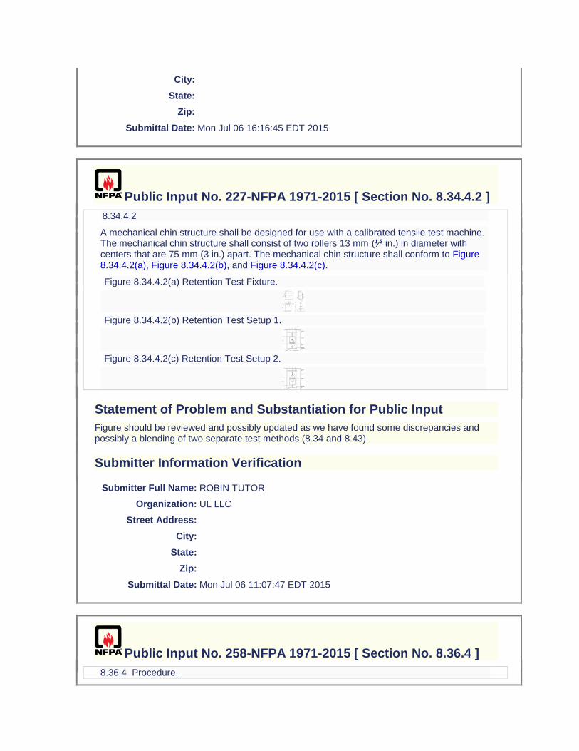
City:
State:
Zip:
Submittal Date: Mon Jul 06 16:16:45 EDT 2015
Public Input No. 227-NFPA 1971-2015 [ Section No. 8.34.4.2 ]
8.34.4.2
A mechanical chin structure shall be designed for use with a calibrated tensile test machine. The mechanical chin structure shall consist of two rollers 13 mm (1⁄2 in.) in diameter with centers that are 75 mm (3 in.) apart. The mechanical chin structure shall conform to Figure 8.34.4.2(a), Figure 8.34.4.2(b), and Figure 8.34.4.2(c).
Figure 8.34.4.2(a) Retention Test Fixture.
Figure 8.34.4.2(b) Retention Test Setup 1.
Figure 8.34.4.2(c) Retention Test Setup 2.
Statement of Problem and Substantiation for Public Input
Figure should be reviewed and possibly updated as we have found some discrepancies and possibly a blending of two separate test methods (8.34 and 8.43).
Submitter Information Verification
Submitter Full Name: ROBIN TUTOR
Organization: UL LLC
Street Address:
City:
State:
Zip:
Submittal Date: Mon Jul 06 11:07:47 EDT 2015
Public Input No. 258-NFPA 1971-2015 [ Section No. 8.36.4 ]
8.36.4 Procedure.
8.36.4.1
Test subjects shall be selected so that their hand dimensions are as close as possible to the middle of the range for hand length and hand circumference as specified in the tables provided for size small and size large gloves in 6.7.6. Three test subjects shall be selected for size small and three for size large.
8.36.4.2
Each donning trial shall start with the glove lying in front of the test subject and shall end when the test subject's fingers are seated in the specimen glove.
8.36.4.3
The time to don one glove of the pair specimen shall be determined by measuring the time it takes for the test subject to don the single glove on three consecutive trials without altering the specimen glove linings between donning. The test subject shall be permitted to don either the right hand glove or left hand glove according to individual preference.
8.36.4.3.1
The glove shall be donned in accordance with the manufacturer's donning procedure.
8.36.4.3.2
The glove shall then be removed by grasping the fingertip of the middle finger and pulling the hand out of the glove.
8.36.4.3.3
The test subject shall wear the glove of the opposite hand during the test.
8.36.4.3.4
Where the glove cannot be donned because of detachment of the inner liner or moisture barrier, then the trial for that glove shall be stopped. If any fingers cannot be fully inserted into the glove, then the trial for that glove shall be stopped.
8.36.4.4
The dry hand donning time shall be the average of the first three dry hand donning times as determined in 8.36.4.3.
8.36.4.5
The test subject shall repeat the trial specified in 8.36.4.3 for each pair of gloves.
8.36.4.6
The test hand shall then be completely submerged in room temperature water [21°C ± 3°C (70°F ± 5°F)] for 10 seconds before doffing the glove each time.
8.36.4.7 6
Immediately after the hand wetting procedure specified in 8.36.4.6, with no time lapse, the test subject shall then don one glove of the pair specimen. The test subject shall do this for three consecutive trials, for each specimen pair of gloves, as specified in 8.36.4.3 and 8.36.4.5. The times shall be recorded.
8.36.4.8 7
The wet hand donning time shall be the average of the first three wet hand donning times as determined in 8.36.4.7.
8.36.4.8
Each test subject shall perform the test with one pair of gloves.
Statement of Problem and Substantiation for Public Input
Proposing that three subjects be used for size small and size large as is consistent with other human subject glove tests.
Submitter Information Verification
Submitter Full Name: ROBIN TUTOR
Organization: UL LLC
Street Address:
City:
State:
Zip:
Submittal Date: Mon Jul 06 16:44:21 EDT 2015
Public Input No. 74-NFPA 1971-2015 [ Section No. 8.36.4.6 ]
8.36.4.6
The test hand shall then be completely submerged in room temperature water [21°C ± 3°C (70°F ± 5°F)] for 10 seconds before doffing donning the glove each time.
Statement of Problem and Substantiation for Public Input
Editorial change
Submitter Information Verification
Submitter Full Name: Michael McKenna
Organization: Michael McKenna & Associates,
Street Address:
City:
State:
Zip:
Submittal Date: Wed Apr 01 14:40:14 EDT 2015
Public Input No. 156-NFPA 1971-2015 [ Section No. 8.36.4.7 ]
8.36.4.7
Immediately after the hand wetting procedure specified in 8.36.4.6, with no time lapse, the test subject shall then don one glove of the pair specimen. The test subject shall do this wetting and donning procedure for three consecutive trials, for each specimen pair of gloves, as specified in 8.36.4.3, 8.36.5, and 8.36.4.56. The times shall be recorded.
Statement of Problem and Substantiation for Public Input
Clarifies that the hand is wet before each individual donning of the glove.
Submitter Information Verification
Submitter Full Name: ROBIN TUTOR
Organization: UL LLC
Street Address:
City:
State:
Zip:
Submittal Date: Mon Jun 29 14:12:01 EDT 2015
Public Input No. 75-NFPA 1971-2015 [ Section No. 8.37.4 ]
8.37.4 Apparatus.
The apparatus shall be as specified in ASTM F 2010, Standard Test Method for Evaluation of Glove Effects on Wearer Hand Dexterity Using a Modified Pegboard Test with the modification that the stainless steel pins shall be within with a medium knurled 30 degree (25 teeth/in.) surface.
Statement of Problem and Substantiation for Public Input
Typo. See TIA 07-5
Submitter Information Verification
Submitter Full Name: Michael McKenna
Organization: Michael McKenna & Associates,
Street Address:
City:
State:
Zip:
Submittal Date: Wed Apr 01 14:41:46 EDT 2015

Public Input No. 20-NFPA 1971-2013 [ Section No. 8.38.2.1 ]
8.38.2.1
Samples for conditioning shall be whole glovesglove pairs.
Additional Proposed Changes
File Name Description Approved
Proposed_TIA_1100_1971_.docx Balloted TIA
Statement of Problem and Substantiation for Public Input
Note: This Public Input originates from Tentative Interim Amendment 1971-13-3 (TIA 1100) issued by the Standards Council on August 1, 2013. As currently written, more information is needed to fully explain how the pulls are to be performed, and also how the graphic results are to be interpreted. This is necessary to ensure consistent testing is performed. The test method as currently written does not provide sufficient detail in order for the test to be consistently applied in the evaluation of glove grip and requires interpretation of the testing laboratory to determine the appropriate body and hand position, which have a significant impact on the test results. Specific changes have been proposed in the position of the test subject’s body and hands that alter the original instructions for performing the test. The additional details are intended to ensure that laboratories performing this test conduct the test in exactly the same way. Photographs of the proper positioning of the test subject body and hands with respect to the pole are included in the proposed modifications to provide a clear interpretation for running this part of the test. In addition, it is proposed to base the performance of glove grip on a change in the measured force relative to the time interval in which that change occurs. Consequently, the criteria in paragraph 7.7.22 have been modified. This modification was necessary because the degree of test subject hand slipping on the pole can occur at varying rates (force over time) leading to widely different application of the test results and potential failure of gloves that are considered to have acceptable performance. These changes were developed as the result of a meeting between Intertek Testing Services, the North Carolina State University Textile Protection and Comfort Center, and Underwriters’ Laboratories, where these organizations worked together to determine how to consistently run the test method and achieve better precision in test results. The involvement of these organizations and their work on this test method were pursuant to a recommendation made by the Technical Committee on Structural and Proximity Fire Fighting Protective Clothing during a committee teleconference held December 2012 where specific problems with the test method and its application in NFPA 1971 were identified. Emergency Nature: The document contains an error or an omission that was overlooked during a regular revision process. After interlaboratory coordination it was determined that the additional language is necessary to perform consistent testing and to ensure a consistent level of compliant product available to users.
Submitter Information Verification
Submitter Full Name:
TC on FAE-SPF
Organization: TC on Structural and Proximity Fire Fighting Protective Clothing and Equipment
Street Address:

City:
State:
Zip:
Submittal Date: Fri Sep 06 08:08:43 EDT 2013
Public Input No. 21-NFPA 1971-2013 [ Section No. 8.38.3.4 ]
8.38.3.4
Specimen glove pairs shall be tested after being wet conditioned for wet conditions as specified in 8.1.9.
Additional Proposed Changes
File Name Description Approved
Proposed_TIA_1100_1971_.docx Balloted TIA
Statement of Problem and Substantiation for Public Input
Note: This Public Input originates from Tentative Interim Amendment 1971-13-3 (TIA 1100) issued by the Standards Council on August 1, 2013. As currently written, more information is needed to fully explain how the pulls are to be performed, and also how the graphic results are to be interpreted. This is necessary to ensure consistent testing is performed. The test method as currently written does not provide sufficient detail in order for the test to be consistently applied in the evaluation of glove grip and requires interpretation of the testing laboratory to determine the appropriate body and hand position, which have a significant impact on the test results. Specific changes have been proposed in the position of the test subject’s body and hands that alter the original instructions for performing the test. The additional details are intended to ensure that laboratories performing this test conduct the test in exactly the same way. Photographs of the proper positioning of the test subject body and hands with respect to the pole are included in the proposed modifications to provide a clear interpretation for running this part of the test. In addition, it is proposed to base the performance of glove grip on a change in the measured force relative to the time interval in which that change occurs. Consequently, the criteria in paragraph 7.7.22 have been modified. This modification was necessary because the degree of test subject hand slipping on the pole can occur at varying rates (force over time) leading to widely different application of the test results and potential failure of gloves that are considered to have acceptable performance. These changes were developed as the result of a meeting between Intertek Testing Services, the North Carolina State University Textile Protection and Comfort Center, and Underwriters’ Laboratories, where these organizations worked together to determine how to consistently run the test method and achieve better precision in test results. The involvement of these organizations and their work on this test method were pursuant to a recommendation made by the Technical Committee on Structural and Proximity Fire Fighting Protective Clothing during a committee teleconference held December 2012 where specific problems with the test method and its application in NFPA 1971 were identified. Emergency Nature: The document contains an error or an omission that was overlooked during a regular revision process. After interlaboratory coordination it was determined that the additional language is necessary to perform consistent testing and to ensure a consistent level of compliant product available to users.
Submitter Information Verification
Submitter Full Name:
TC on FAE-SPF
Organization: TC on Structural and Proximity Fire Fighting Protective Clothing and Equipment
Street Address:
City:
State:
Zip:
Submittal Date: Fri Sep 06 08:12:12 EDT 2013
Public Input No. 22-NFPA 1971-2013 [ Section No. 8.38.4.1 ]
8.38.4.1 Pulling Device.
The pulling device shall be a 3.2 cm (1 1⁄4 in.) diameter fiberglass pole attached to an overhead calibrated force measuring device in such a fashion that pulls on the pole will be perpendicular to the ground and downward in direction. This pole shall be used until surface degradation occurs. The force measuring system shall provide a graphical plot of force-vs-time.
Additional Proposed Changes
File Name Description Approved
Proposed_TIA_1100_1971_.docx Balloted TIA
Statement of Problem and Substantiation for Public Input
Note: This Public Input originates from Tentative Interim Amendment 1971-13-3 (TIA 1100) issued by the Standards Council on August 1, 2013. As currently written, more information is needed to fully explain how the pulls are to be performed, and also how the graphic results are to be interpreted. This is necessary to ensure consistent testing is performed. The test method as currently written does not provide sufficient detail in order for the test to be consistently applied in the evaluation of glove grip and requires interpretation of the testing laboratory to determine the appropriate body and hand position, which have a significant impact on the test results. Specific changes have been proposed in the position of the test subject’s body and hands that alter the original instructions for performing the test. The additional details are intended to ensure that laboratories performing this test conduct the test in exactly the same way. Photographs of the proper positioning of the test subject body and hands with respect to the pole are included in the proposed modifications to provide a clear interpretation for running this part of the test. In addition, it is proposed to base the performance of glove grip on a change in the measured force relative to the time interval in which that change occurs. Consequently, the criteria in paragraph 7.7.22 have been modified. This modification was necessary because the degree of test subject hand slipping on the pole can occur at varying rates (force over time) leading to widely different application of the test results and potential failure of gloves that are considered to have acceptable performance. These changes were
developed as the result of a meeting between Intertek Testing Services, the North Carolina State University Textile Protection and Comfort Center, and Underwriters’ Laboratories, where these organizations worked together to determine how to consistently run the test method and achieve better precision in test results. The involvement of these organizations and their work on this test method were pursuant to a recommendation made by the Technical Committee on Structural and Proximity Fire Fighting Protective Clothing during a committee teleconference held December 2012 where specific problems with the test method and its application in NFPA 1971 were identified. Emergency Nature: The document contains an error or an omission that was overlooked during a regular revision process. After interlaboratory coordination it was determined that the additional language is necessary to perform consistent testing and to ensure a consistent level of compliant product available to users.
Submitter Information Verification
Submitter Full Name:
TC on FAE-SPF
Organization: TC on Structural and Proximity Fire Fighting Protective Clothing and Equipment
Street Address:
City:
State:
Zip:
Submittal Date: Fri Sep 06 08:14:18 EDT 2013
Public Input No. 23-NFPA 1971-2013 [ Section No. 8.38.5.1 ]
8.38.5.1
Test subjects shall be selected so that their hand dimensions are as close as possible to the middle of the range for hand length and hand circumference as specified in Table 6.7.6.1(ab) and Table 6.7.6.1(d) for size small and size large gloves. At least three test subjects shall be selected for both size small and size large.
Additional Proposed Changes
File Name Description Approved
Proposed_TIA_1100_1971_.docx Balloted TIA
Statement of Problem and Substantiation for Public Input
Note: This Public Input originates from Tentative Interim Amendment 1971-13-3 (TIA 1100) issued by the Standards Council on August 1, 2013. As currently written, more information is needed to fully explain how the pulls are to be performed, and also how the graphic results are to be interpreted. This is necessary to ensure consistent testing is performed. The test method as currently written does not provide sufficient detail in order for the test to be consistently applied in the evaluation of glove grip and requires interpretation of the testing laboratory to determine the appropriate body and hand position, which have a significant impact on the test results. Specific changes have been proposed in the position of the test subject’s body and
hands that alter the original instructions for performing the test. The additional details are intended to ensure that laboratories performing this test conduct the test in exactly the same way. Photographs of the proper positioning of the test subject body and hands with respect to the pole are included in the proposed modifications to provide a clear interpretation for running this part of the test. In addition, it is proposed to base the performance of glove grip on a change in the measured force relative to the time interval in which that change occurs. Consequently, the criteria in paragraph 7.7.22 have been modified. This modification was necessary because the degree of test subject hand slipping on the pole can occur at varying rates (force over time) leading to widely different application of the test results and potential failure of gloves that are considered to have acceptable performance. These changes were developed as the result of a meeting between Intertek Testing Services, the North Carolina State University Textile Protection and Comfort Center, and Underwriters’ Laboratories, where these organizations worked together to determine how to consistently run the test method and achieve better precision in test results. The involvement of these organizations and their work on this test method were pursuant to a recommendation made by the Technical Committee on Structural and Proximity Fire Fighting Protective Clothing during a committee teleconference held December 2012 where specific problems with the test method and its application in NFPA 1971 were identified. Emergency Nature: The document contains an error or an omission that was overlooked during a regular revision process. After interlaboratory coordination it was determined that the additional language is necessary to perform consistent testing and to ensure a consistent level of compliant product available to users.
Submitter Information Verification
Submitter Full Name:
TC on FAE-SPF
Organization: TC on Structural and Proximity Fire Fighting Protective Clothing and Equipment
Street Address:
City:
State:
Zip:
Submittal Date: Fri Sep 06 08:37:14 EDT 2013
Public Input No. 24-NFPA 1971-2013 [ Section No. 8.38.5.4 ]
8.38.5.4
The test subject shall then make three pulls on the pulling device with gloves with peak and minimum pull force values measured. Pulls shall be performed as described and the test subject's hand shall be positioned as shown in Figure 8.38.5.4.1 through (a) and Figure 8.38.5.4(b), and as described below:
INSERT FIGURE 8.38.5.4.6. The test subject shall extend the arms in front of the body at shoulder height to grab the pulling device for pulling vertically down from the ceiling. (a) HERE (see uploaded file from the balloted TIA)
Figure 8.38.5.4(a) Position of test subject body, arms, and hands with respect to pole. Photo Countesy Intertek Testing Services, Used by Permission.
INSERT FIGURE 8.38.5.4(b) HERE (see uploaded file from the balloted TIA)
Figure 8.38.5.4
.1 The test subject shall stand with feet together, firmly planted on the ground, and knees slightly bent
(b) Close-up of position of test subject hands on pole. Photo Countesy Intertek Testing Services, Used by Permission.
8.38.5.4.21
The stand shall be adjusted such that the cushioned bar is touching the test subject’s chest. The stand shall prevent the test subject's forward movement during the pulltest subject shall stand facing the pole with feet shoulder width apart.
8.38.5.4.32
The While wearing specimen gloves, the test subject shall stand in a comfortable pulling position with the arms bent at an angle of approximately 90 degrees and, in any case, the arms shall not be completely extended or touching the bodygrasp the pole with the bottom of the bottom hand at a height equal to the height of the subject.
8.38.5.4.43
The test subject shall grasp the pulling device with hands next to each other. Thumbs hands shall be stacked on each other and the thumbs shall not overlap the fingers.
8.38.5.4.54
The test subject shall pull the rope or pole with as much pulling force as possible in a smooth, steady, swift, and non-jerking action. The test subject shall not bend the knees further or pull down with body weight during the pullbody shall be distanced from the pole so that the forearms are approaching vertical and in plane with the pole.
8.38.5.4.65
The test subject shall continuously pull on the pulling device for a minimum of 5 seconds, +1/-0 seconds. The test subject shall continue to pull until the test facilitator observes a peak pulling force and instructs the test subject to end the pullelbows shall be shoulder width apart, rotated neither fully in (arms parallel to the pole) nor fully out (arms perpendicular to the pole).
Additional Proposed Changes
File Name Description Approved
Proposed_TIA_1100_1971_.docx Balloted TIA
Statement of Problem and Substantiation for Public Input
Note: This Public Input originates from Tentative Interim Amendment 1971-13-3 (TIA 1100) issued by the Standards Council on August 1, 2013. As currently written, more information is needed to fully explain how the pulls are to be performed, and also how the graphic results are to be interpreted. This is necessary to ensure consistent testing is performed. The test method as currently written does not provide sufficient detail in order for the test to be consistently applied in the evaluation of glove grip and requires interpretation of the testing laboratory to determine the appropriate body and hand position, which have a significant impact on the test results. Specific changes have been proposed in the position of the test subject’s body and hands that alter the original instructions for performing the test. The additional details are intended to ensure that laboratories performing this test conduct the test in exactly the same
way. Photographs of the proper positioning of the test subject body and hands with respect to the pole are included in the proposed modifications to provide a clear interpretation for running this part of the test. In addition, it is proposed to base the performance of glove grip on a change in the measured force relative to the time interval in which that change occurs. Consequently, the criteria in paragraph 7.7.22 have been modified. This modification was necessary because the degree of test subject hand slipping on the pole can occur at varying rates (force over time) leading to widely different application of the test results and potential failure of gloves that are considered to have acceptable performance. These changes were developed as the result of a meeting between Intertek Testing Services, the North Carolina State University Textile Protection and Comfort Center, and Underwriters’ Laboratories, where these organizations worked together to determine how to consistently run the test method and achieve better precision in test results. The involvement of these organizations and their work on this test method were pursuant to a recommendation made by the Technical Committee on Structural and Proximity Fire Fighting Protective Clothing during a committee teleconference held December 2012 where specific problems with the test method and its application in NFPA 1971 were identified. Emergency Nature: The document contains an error or an omission that was overlooked during a regular revision process. After interlaboratory coordination it was determined that the additional language is necessary to perform consistent testing and to ensure a consistent level of compliant product available to users.
Submitter Information Verification
Submitter Full Name:
TC on FAE-SPF
Organization: TC on Structural and Proximity Fire Fighting Protective Clothing and Equipment
Street Address:
City:
State:
Zip:
Submittal Date: Fri Sep 06 08:39:45 EDT 2013
Public Input No. 76-NFPA 1971-2015 [ Section No. 8.38.5.4.2 ]
8.38.5.4.2
The stand shall be adjusted such that the cushioned bar is touching the test subject’s chest. The stand shall prevent the test subject's forward movement during the pull.
Statement of Problem and Substantiation for Public Input
The final version of the new grip test is found in ROC 1971-136 which removed the stand from the apparatus section. However, the stand language within the procedure was accidentally left in the comment. This should be removed as it conflicts with the apparatus.
Submitter Information Verification
Submitter Full Name: Michael McKenna
Organization: Michael McKenna & Associates,
Street Address:
City:
State:
Zip:
Submittal Date: Wed Apr 01 14:43:47 EDT 2015
Public Input No. 25-NFPA 1971-2013 [ Section No. 8.38.5.5 ]
8.38.5.5 The test subject shall pull the pole with as much pulling force as possible in a
smooth, steady, swift, and non-jerking action for 5 +1/-0 seconds. The test subject shall minimize forward or backward movement during the pull as much as possible. The test subject shall not bend the knees or pull down with body weight during the pull. The test subject shall continue to pull until the test facilitator instructs the test subject to end the pull at 5 +1/-0 seconds. 8.38.5.6 The test subject shall repeat the pull described above for a total of three pulls.
8.38.5.5
The percentage of barehanded control value shall be calculated as follows:
where:
PFg = average pulling force with gloves
CVb = barehanded control value
Additional Proposed Changes
File Name Description Approved
Proposed_TIA_1100_1971_.docx Balloted TIA
Statement of Problem and Substantiation for Public Input
Note: This Public Input originates from Tentative Interim Amendment 1971-13-3 (TIA 1100) issued by the Standards Council on August 1, 2013. As currently written, more information is needed to fully explain how the pulls are to be performed, and also how the graphic results are to be interpreted. This is necessary to ensure consistent testing is performed. The test method as currently written does not provide sufficient detail in order for the test to be consistently applied in the evaluation of glove grip and requires interpretation of the testing laboratory to determine the appropriate body and hand position, which have a significant impact on the test results. Specific changes have been proposed in the position of the test subject’s body and hands that alter the original instructions for performing the test. The additional details are intended to ensure that laboratories performing this test conduct the test in exactly the same way. Photographs of the proper positioning of the test subject body and hands with respect to
the pole are included in the proposed modifications to provide a clear interpretation for running this part of the test. In addition, it is proposed to base the performance of glove grip on a change in the measured force relative to the time interval in which that change occurs. Consequently, the criteria in paragraph 7.7.22 have been modified. This modification was necessary because the degree of test subject hand slipping on the pole can occur at varying rates (force over time) leading to widely different application of the test results and potential failure of gloves that are considered to have acceptable performance. These changes were developed as the result of a meeting between Intertek Testing Services, the North Carolina State University Textile Protection and Comfort Center, and Underwriters’ Laboratories, where these organizations worked together to determine how to consistently run the test method and achieve better precision in test results. The involvement of these organizations and their work on this test method were pursuant to a recommendation made by the Technical Committee on Structural and Proximity Fire Fighting Protective Clothing during a committee teleconference held December 2012 where specific problems with the test method and its application in NFPA 1971 were identified. Emergency Nature: The document contains an error or an omission that was overlooked during a regular revision process. After interlaboratory coordination it was determined that the additional language is necessary to perform consistent testing and to ensure a consistent level of compliant product available to users.
Submitter Information Verification
Submitter Full Name:
TC on FAE-SPF
Organization: TC on Structural and Proximity Fire Fighting Protective Clothing and Equipment
Street Address:
City:
State:
Zip:
Submittal Date: Fri Sep 06 08:59:02 EDT 2013
Public Input No. 26-NFPA 1971-2013 [ Sections 8.38.6.1, 8.38.6.2, 8.38.6.3 ]
Sections 8.38.6.1, 8.38.6.2, 8.38.6.3
8.38.6.1
The peak pull force value for each individual pull shall be recorded and reported.
8.38.6.2
The minimum pull force value occurring after the peak pull force value Any drop in force of greater than 30% in any 0.2-second interval, as measured in the graphical plot of force-vs-time, shall be recorded and reported.
8.38.6.3
The percentage drop between the peak pull force value and the minimum pull force value shall be calculated, recorded, and reported.
Additional Proposed Changes
File Name Description Approved
Proposed_TIA_1100_1971_.docx Balloted TIA
Statement of Problem and Substantiation for Public Input
Note: This Public Input originates from Tentative Interim Amendment 1971-13-3 (TIA 1100) issued by the Standards Council on August 1, 2013. As currently written, more information is needed to fully explain how the pulls are to be performed, and also how the graphic results are to be interpreted. This is necessary to ensure consistent testing is performed. The test method as currently written does not provide sufficient detail in order for the test to be consistently applied in the evaluation of glove grip and requires interpretation of the testing laboratory to determine the appropriate body and hand position, which have a significant impact on the test results. Specific changes have been proposed in the position of the test subject’s body and hands that alter the original instructions for performing the test. The additional details are intended to ensure that laboratories performing this test conduct the test in exactly the same way. Photographs of the proper positioning of the test subject body and hands with respect to the pole are included in the proposed modifications to provide a clear interpretation for running this part of the test. In addition, it is proposed to base the performance of glove grip on a change in the measured force relative to the time interval in which that change occurs. Consequently, the criteria in paragraph 7.7.22 have been modified. This modification was necessary because the degree of test subject hand slipping on the pole can occur at varying rates (force over time) leading to widely different application of the test results and potential failure of gloves that are considered to have acceptable performance. These changes were developed as the result of a meeting between Intertek Testing Services, the North Carolina State University Textile Protection and Comfort Center, and Underwriters’ Laboratories, where these organizations worked together to determine how to consistently run the test method and achieve better precision in test results. The involvement of these organizations and their work on this test method were pursuant to a recommendation made by the Technical Committee on Structural and Proximity Fire Fighting Protective Clothing during a committee teleconference held December 2012 where specific problems with the test method and its application in NFPA 1971 were identified. Emergency Nature: The document contains an error or an omission that was overlooked during a regular revision process. After interlaboratory coordination it was determined that the additional language is necessary to perform consistent testing and to ensure a consistent level of compliant product available to users.
Submitter Information Verification
Submitter Full Name:
TC on FAE-SPF
Organization: TC on Structural and Proximity Fire Fighting Protective Clothing and Equipment
Street Address:
City:
State:
Zip:
Submittal Date: Fri Sep 06 09:02:02 EDT 2013
Public Input No. 27-NFPA 1971-2013 [ Section No. 8.38.7.1 ]
8.38.7.1
The individual percentage drop between the peak pull force value and the minimum pull force value shall be used to determine pass or fail Any drop in force of greater than 30% in any 0.2-second interval shall constitute failing performance.
Additional Proposed Changes
File Name Description Approved
Proposed_TIA_1100_1971_.docx Balloted TIA
Statement of Problem and Substantiation for Public Input
Note: This Public Input originates from Tentative Interim Amendment 1971-13-3 (TIA 1100) issued by the Standards Council on August 1, 2013. As currently written, more information is needed to fully explain how the pulls are to be performed, and also how the graphic results are to be interpreted. This is necessary to ensure consistent testing is performed. The test method as currently written does not provide sufficient detail in order for the test to be consistently applied in the evaluation of glove grip and requires interpretation of the testing laboratory to determine the appropriate body and hand position, which have a significant impact on the test results. Specific changes have been proposed in the position of the test subject’s body and hands that alter the original instructions for performing the test. The additional details are intended to ensure that laboratories performing this test conduct the test in exactly the same way. Photographs of the proper positioning of the test subject body and hands with respect to the pole are included in the proposed modifications to provide a clear interpretation for running this part of the test. In addition, it is proposed to base the performance of glove grip on a change in the measured force relative to the time interval in which that change occurs. Consequently, the criteria in paragraph 7.7.22 have been modified. This modification was necessary because the degree of test subject hand slipping on the pole can occur at varying rates (force over time) leading to widely different application of the test results and potential failure of gloves that are considered to have acceptable performance. These changes were developed as the result of a meeting between Intertek Testing Services, the North Carolina State University Textile Protection and Comfort Center, and Underwriters’ Laboratories, where these organizations worked together to determine how to consistently run the test method and achieve better precision in test results. The involvement of these organizations and their work on this test method were pursuant to a recommendation made by the Technical Committee on Structural and Proximity Fire Fighting Protective Clothing during a committee teleconference held December 2012 where specific problems with the test method and its application in NFPA 1971 were identified. Emergency Nature: The document contains an error or an omission that was overlooked during a regular revision process. After interlaboratory coordination it was determined that the additional language is necessary to perform consistent testing and to ensure a consistent level of compliant product available to users.
Submitter Information Verification
Submitter Full Name:
TC on FAE-SPF
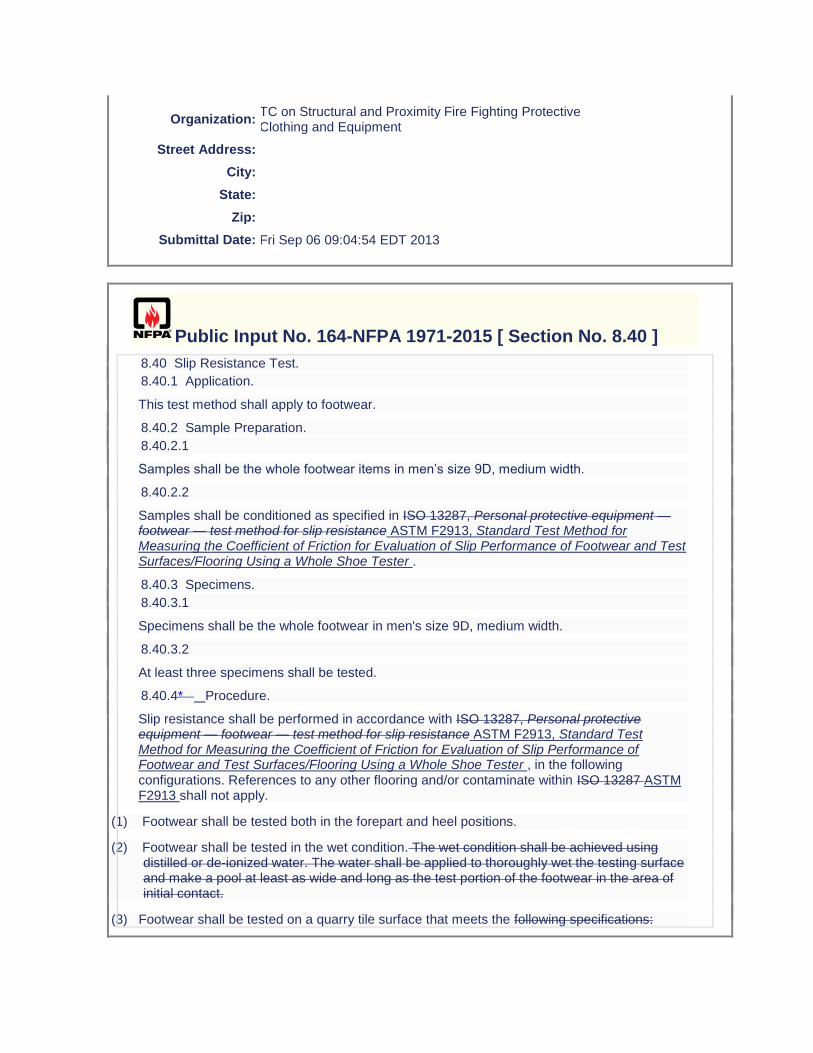
Organization: TC on Structural and Proximity Fire Fighting Protective Clothing and Equipment
Street Address:
City:
State:
Zip:
Submittal Date: Fri Sep 06 09:04:54 EDT 2013
Public Input No. 164-NFPA 1971-2015 [ Section No. 8.40 ]
8.40 Slip Resistance Test.
8.40.1 Application.
This test method shall apply to footwear.
8.40.2 Sample Preparation.
8.40.2.1
Samples shall be the whole footwear items in men’s size 9D, medium width.
8.40.2.2
Samples shall be conditioned as specified in ISO 13287, Personal protective equipment — footwear — test method for slip resistance ASTM F2913, Standard Test Method for Measuring the Coefficient of Friction for Evaluation of Slip Performance of Footwear and Test Surfaces/Flooring Using a Whole Shoe Tester .
8.40.3 Specimens.
8.40.3.1
Specimens shall be the whole footwear in men's size 9D, medium width.
8.40.3.2
At least three specimens shall be tested.
8.40.4* Procedure.
Slip resistance shall be performed in accordance with ISO 13287, Personal protective equipment — footwear — test method for slip resistance ASTM F2913, Standard Test Method for Measuring the Coefficient of Friction for Evaluation of Slip Performance of Footwear and Test Surfaces/Flooring Using a Whole Shoe Tester , in the following configurations. References to any other flooring and/or contaminate within ISO 13287 ASTM F2913 shall not apply.
(1) Footwear shall be tested both in the forepart and heel positions.
(2) Footwear shall be tested in the wet condition. The wet condition shall be achieved using distilled or de-ionized water. The water shall be applied to thoroughly wet the testing surface and make a pool at least as wide and long as the test portion of the footwear in the area of initial contact.
(3) Footwear shall be tested on a quarry tile surface that meets the following specifications:
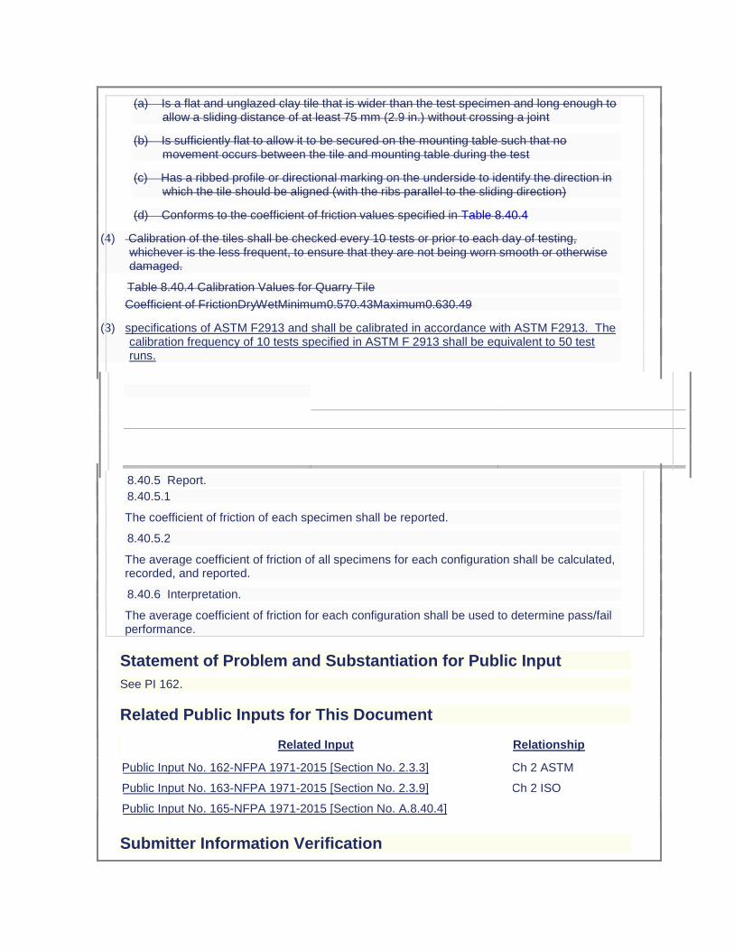
(a) Is a flat and unglazed clay tile that is wider than the test specimen and long enough to allow a sliding distance of at least 75 mm (2.9 in.) without crossing a joint
(b) Is sufficiently flat to allow it to be secured on the mounting table such that no movement occurs between the tile and mounting table during the test
(c) Has a ribbed profile or directional marking on the underside to identify the direction in which the tile should be aligned (with the ribs parallel to the sliding direction)
(d) Conforms to the coefficient of friction values specified in Table 8.40.4
(4) Calibration of the tiles shall be checked every 10 tests or prior to each day of testing, whichever is the less frequent, to ensure that they are not being worn smooth or otherwise damaged.
Table 8.40.4 Calibration Values for Quarry Tile
Coefficient of FrictionDryWetMinimum0.570.43Maximum0.630.49
(3) specifications of ASTM F2913 and shall be calibrated in accordance with ASTM F2913. The calibration frequency of 10 tests specified in ASTM F 2913 shall be equivalent to 50 test runs.
8.40.5 Report.
8.40.5.1
The coefficient of friction of each specimen shall be reported.
8.40.5.2
The average coefficient of friction of all specimens for each configuration shall be calculated, recorded, and reported.
8.40.6 Interpretation.
The average coefficient of friction for each configuration shall be used to determine pass/fail performance.
Statement of Problem and Substantiation for Public Input
See PI 162.
Related Public Inputs for This Document
Related Input Relationship
Public Input No. 162-NFPA 1971-2015 [Section No. 2.3.3] Ch 2 ASTM
Public Input No. 163-NFPA 1971-2015 [Section No. 2.3.9] Ch 2 ISO
Public Input No. 165-NFPA 1971-2015 [Section No. A.8.40.4]
Submitter Information Verification
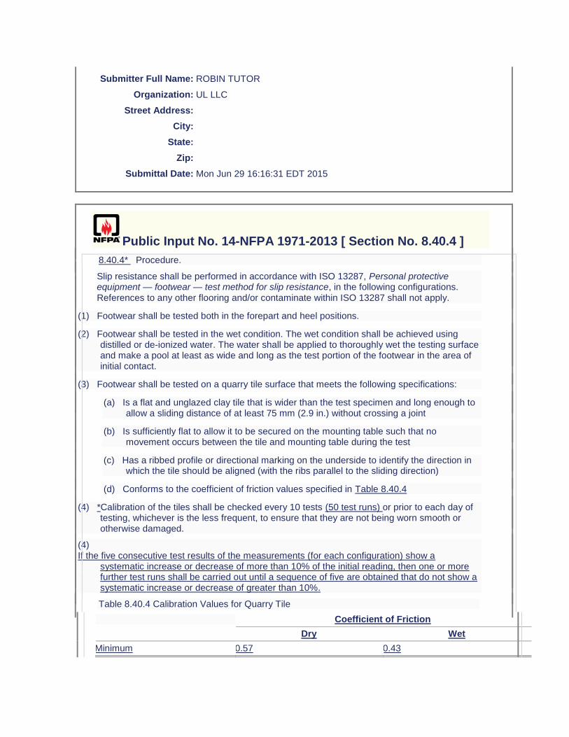
Submitter Full Name: ROBIN TUTOR
Organization: UL LLC
Street Address:
City:
State:
Zip:
Submittal Date: Mon Jun 29 16:16:31 EDT 2015
Public Input No. 14-NFPA 1971-2013 [ Section No. 8.40.4 ]
8.40.4* Procedure.
Slip resistance shall be performed in accordance with ISO 13287, Personal protective equipment — footwear — test method for slip resistance, in the following configurations. References to any other flooring and/or contaminate within ISO 13287 shall not apply.
(1) Footwear shall be tested both in the forepart and heel positions.
(2) Footwear shall be tested in the wet condition. The wet condition shall be achieved using distilled or de-ionized water. The water shall be applied to thoroughly wet the testing surface and make a pool at least as wide and long as the test portion of the footwear in the area of initial contact.
(3) Footwear shall be tested on a quarry tile surface that meets the following specifications:
(a) Is a flat and unglazed clay tile that is wider than the test specimen and long enough to allow a sliding distance of at least 75 mm (2.9 in.) without crossing a joint
(b) Is sufficiently flat to allow it to be secured on the mounting table such that no movement occurs between the tile and mounting table during the test
(c) Has a ribbed profile or directional marking on the underside to identify the direction in which the tile should be aligned (with the ribs parallel to the sliding direction)
(d) Conforms to the coefficient of friction values specified in Table 8.40.4
(4) *Calibration of the tiles shall be checked every 10 tests (50 test runs) or prior to each day of testing, whichever is the less frequent, to ensure that they are not being worn smooth or otherwise damaged.
(4) If the five consecutive test results of the measurements (for each configuration) show a
systematic increase or decrease of more than 10% of the initial reading, then one or more further test runs shall be carried out until a sequence of five are obtained that do not show a systematic increase or decrease of greater than 10%.
Table 8.40.4 Calibration Values for Quarry Tile
Coefficient of Friction
Dry Wet
Minimum 0.57 0.43
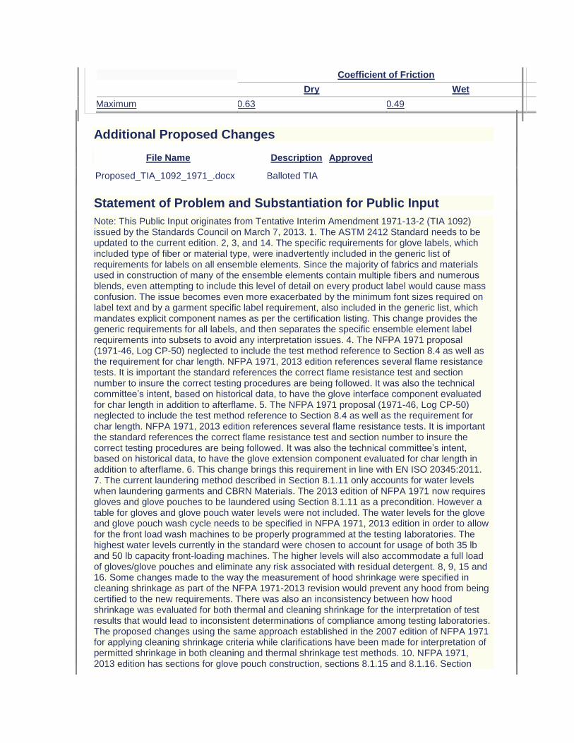
Coefficient of Friction
Dry Wet
Maximum 0.63 0.49
Additional Proposed Changes
File Name Description Approved
Proposed_TIA_1092_1971_.docx Balloted TIA
Statement of Problem and Substantiation for Public Input
Note: This Public Input originates from Tentative Interim Amendment 1971-13-2 (TIA 1092) issued by the Standards Council on March 7, 2013. 1. The ASTM 2412 Standard needs to be updated to the current edition. 2, 3, and 14. The specific requirements for glove labels, which included type of fiber or material type, were inadvertently included in the generic list of requirements for labels on all ensemble elements. Since the majority of fabrics and materials used in construction of many of the ensemble elements contain multiple fibers and numerous blends, even attempting to include this level of detail on every product label would cause mass confusion. The issue becomes even more exacerbated by the minimum font sizes required on label text and by a garment specific label requirement, also included in the generic list, which mandates explicit component names as per the certification listing. This change provides the generic requirements for all labels, and then separates the specific ensemble element label requirements into subsets to avoid any interpretation issues. 4. The NFPA 1971 proposal (1971-46, Log CP-50) neglected to include the test method reference to Section 8.4 as well as the requirement for char length. NFPA 1971, 2013 edition references several flame resistance tests. It is important the standard references the correct flame resistance test and section number to insure the correct testing procedures are being followed. It was also the technical committee’s intent, based on historical data, to have the glove interface component evaluated for char length in addition to afterflame. 5. The NFPA 1971 proposal (1971-46, Log CP-50) neglected to include the test method reference to Section 8.4 as well as the requirement for char length. NFPA 1971, 2013 edition references several flame resistance tests. It is important the standard references the correct flame resistance test and section number to insure the correct testing procedures are being followed. It was also the technical committee’s intent, based on historical data, to have the glove extension component evaluated for char length in addition to afterflame. 6. This change brings this requirement in line with EN ISO 20345:2011. 7. The current laundering method described in Section 8.1.11 only accounts for water levels when laundering garments and CBRN Materials. The 2013 edition of NFPA 1971 now requires gloves and glove pouches to be laundered using Section 8.1.11 as a precondition. However a table for gloves and glove pouch water levels were not included. The water levels for the glove and glove pouch wash cycle needs to be specified in NFPA 1971, 2013 edition in order to allow for the front load wash machines to be properly programmed at the testing laboratories. The highest water levels currently in the standard were chosen to account for usage of both 35 lb and 50 lb capacity front-loading machines. The higher levels will also accommodate a full load of gloves/glove pouches and eliminate any risk associated with residual detergent. 8, 9, 15 and 16. Some changes made to the way the measurement of hood shrinkage were specified in cleaning shrinkage as part of the NFPA 1971-2013 revision would prevent any hood from being certified to the new requirements. There was also an inconsistency between how hood shrinkage was evaluated for both thermal and cleaning shrinkage for the interpretation of test results that would lead to inconsistent determinations of compliance among testing laboratories. The proposed changes using the same approach established in the 2007 edition of NFPA 1971 for applying cleaning shrinkage criteria while clarifications have been made for interpretation of permitted shrinkage in both cleaning and thermal shrinkage test methods. 10. NFPA 1971, 2013 edition has sections for glove pouch construction, sections 8.1.15 and 8.1.16. Section
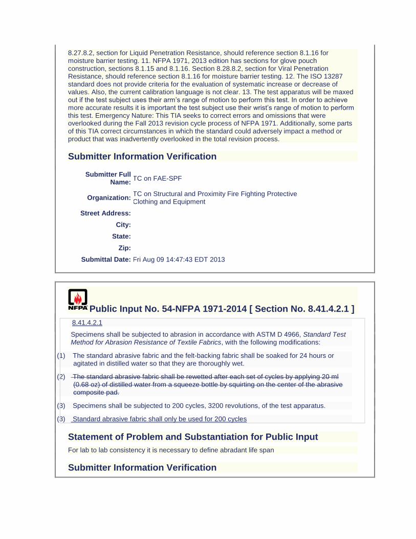
8.27.8.2, section for Liquid Penetration Resistance, should reference section 8.1.16 for moisture barrier testing. 11. NFPA 1971, 2013 edition has sections for glove pouch construction, sections 8.1.15 and 8.1.16. Section 8.28.8.2, section for Viral Penetration Resistance, should reference section 8.1.16 for moisture barrier testing. 12. The ISO 13287 standard does not provide criteria for the evaluation of systematic increase or decrease of values. Also, the current calibration language is not clear. 13. The test apparatus will be maxed out if the test subject uses their arm’s range of motion to perform this test. In order to achieve more accurate results it is important the test subject use their wrist’s range of motion to perform this test. Emergency Nature: This TIA seeks to correct errors and omissions that were overlooked during the Fall 2013 revision cycle process of NFPA 1971. Additionally, some parts of this TIA correct circumstances in which the standard could adversely impact a method or product that was inadvertently overlooked in the total revision process.
Submitter Information Verification
Submitter Full Name:
TC on FAE-SPF
Organization: TC on Structural and Proximity Fire Fighting Protective Clothing and Equipment
Street Address:
City:
State:
Zip:
Submittal Date: Fri Aug 09 14:47:43 EDT 2013
Public Input No. 54-NFPA 1971-2014 [ Section No. 8.41.4.2.1 ]
8.41.4.2.1
Specimens shall be subjected to abrasion in accordance with ASTM D 4966, Standard Test Method for Abrasion Resistance of Textile Fabrics, with the following modifications:
(1) The standard abrasive fabric and the felt-backing fabric shall be soaked for 24 hours or agitated in distilled water so that they are thoroughly wet.
(2) The standard abrasive fabric shall be rewetted after each set of cycles by applying 20 ml (0.68 oz) of distilled water from a squeeze bottle by squirting on the center of the abrasive composite pad.
(3) Specimens shall be subjected to 200 cycles, 3200 revolutions, of the test apparatus.
(3) Standard abrasive fabric shall only be used for 200 cycles
Statement of Problem and Substantiation for Public Input
For lab to lab consistency it is necessary to define abradant life span
Submitter Information Verification
Submitter Full Name: Jason Allen
Organization: Intertek Testing Services
Street Address:
City:
State:
Zip:
Submittal Date: Tue Jul 01 16:27:26 EDT 2014
Public Input No. 80-NFPA 1971-2015 [ Section No. 8.41.9.5 ]
8.41.9.5
For the drying cycles of the laundering durability test specified in 8.41.4.1.1, gloves shall be tumble dried for 60 minutes and shall be removed immediately at the end of the drying cycle. At the conclusion of the final drying cycle, the gloves shall be direct dried on a Williams® G18PX dryer operated forced-air, non-tumble drying mechanism operated at 10ºC (50ºF) /- 5 degrees C above current room temperature for until dry, but not less than 8 hours, +/- 45 minutes.
Statement of Problem and Substantiation for Public Input
ROC 1971-159 replaced the Williams GP18PX Dryer language with generic terms and this was overlooked during editing.
Submitter Information Verification
Submitter Full Name: Michael McKenna
Organization: Michael McKenna & Associates,
Street Address:
City:
State:
Zip:
Submittal Date: Mon Apr 06 14:26:05 EDT 2015
Public Input No. 84-NFPA 1971-2015 [ Section No. 8.41.10.1 ]
8.41.10.1
For testing label legibility after convective heat exposure, specimens shall include complete footwear items with the labels attached or representative sections of the footwear with labels attached.
8.41.10.x
For testing label legibility after abrasion, specimens shall be individual labels.
Statement of Problem and Substantiation for Public Input
This statement was accidentally replaced with the new language in ROP 1971-165 when instead ROP 1971-165 should be been an ADDITIONAL statement. The statement added was for heat exposure which was missing in the last edition. Now the statement for abrasion is missing.
Submitter Information Verification
Submitter Full Name: Michael McKenna
Organization: Michael McKenna & Associates,
Street Address:
City:
State:
Zip:
Submittal Date: Mon Apr 06 14:46:08 EDT 2015
Public Input No. 142-NFPA 1971-2015 [ New Section after 8.45 ]
8.XX Abrasion Resistance of Reflective Coating on Proximity Face Shield
8.XX.1 Application
8.XX.1.1 This test method shall apply to proximity fire fighting protective face shield.
8.XX.1. 2 This test shall apply only to coated materials of the noted element components.
8.XX.2 Samples. The samples shall be complete face shields or reflective coated face shield
material.
8.XX.3 Specimens. The specimens shall be the same as the samples of 8.XX.2
8.XX.4 Apparatus.
8.XX.4.1 No apparatus is required
8.XX.5 Procedure.
8.XX.5.1 Five individual samples shall be tested. No two samples shall come from the same
face shield.
8.XX.5.2 Obtain five individual pieces of "0000" steel wool. use one piece per sample of face
shield.
8.XX.5.3 Mark of a section of the sample 2 inches by 6 inches, which will be the test area.
8.XX.5.4 Take a new piece of "0000" steel wool and with medium hand pressure wipe the
face shield along the complete 6 inches on the outside of the face shield. Perform this five times with the same piece of "0000" steel wool.
8.XX.5.5 Following the fifth pass visually examined for compliance.
8.XX.6 Report.
8.XX.6.1 Evidence of any hazing, marks or scratches on the coating shall be recorded and
reported.
8.XX.7 Interpretation.
8.XX.7.1 Any hazing, marks or scratching of the coating shall constitute failure.
Statement of Problem and Substantiation for Public Input
Substantiation - The standard doesn't have any durability testing of the coating and during fire operations when you try to clear your face shield you can wipe the coating off.
Related Public Inputs for This Document
Related Input Relationship
Public Input No. 145-NFPA 1971-2015 [New Section after 7.7]
Submitter Information Verification
Submitter Full Name: HARRY WINER
Organization: HIP CONSULTING LLC
Street Address:
City:
State:
Zip:
Submittal Date: Mon Jun 29 09:05:33 EDT 2015
Public Input No. 143-NFPA 1971-2015 [ New Section after 8.45 ]
8.XX Adhesion of Reflective Coating on Proximity Face Shield - Tape Method
8.XX.1 Application
8.XX.1.1 This test method shall apply to proximity fire fighting protective face shield.
8.XX.1. 2 This test shall apply only to coated materials of the noted element components.
8.XX.2 Samples. The samples shall be complete face shields or reflective coated face shield
material.
8.XX.3 Specimens. The specimens shall be the same as the samples of 8.XX.2
8.XX.4 Apparatus.
8.XX.4.1 The tensile-testing machine described in ASTM D5034, Standard Test Method for
Breaking Strength and Elongation of Textile Fabrics (Grab Test), shall be used with the modification that all machine attachments for determining maximum load shall be disengaged and the speed of the pulling clamp shall be 505 mm/min (20 in./min).
8.XX.4.2 Five 50 mm × 100 mm (2 in. × 4 in.) steel plates conforming to Class 301 or Class
304 of ASTM A 666, Standard Specification for Annealed or Cold Worked Austenitic Stainless Steel
Sheet, Strip, Plate, and Flat Bar, which have been polished to a No. 4 finish shall be used.
8.XX.4.3 A38 mm (11⁄2 in.) wide steel roller weighing 4.53 kg ± 0.06 kg (10 lb ± 2 oz), shall
be used.
8.XX.4.4 A pressure sensitive tape used for testing the adhesion of the coating or the
laminate shall be used and shall have the required adhesion value specified in 8.54.4.6.11.
8XX.4.5 Candidate pressure sensitive tapes, for potential use in testing the adhesion of
coatings or laminates, shall have the adhesion value of the candidate tapes be determined by the procedure specified in 8.54.4.6.12.
8.XX.4.6 Procedure for Determining Adhesion Value of Candidate Pressure Sensitive Tapes.
8.XX.4.6.1 The equipment specified in 8.54.4.1, 8.54.4.2, and 8.54.4.3 shall be used in the
procedure for adhesion value determination.
8XX.4.6.2 Prior to each adhesion value determination procedure, the steel plates specified in
8.54.4.2 shall be thoroughly cleaned with diacetone alcohol, methyl alcohol, or methyl ethyl ketone, using a clean piece of lint-free wiping tissue.
8.XX.4.6.3 Five specimens from the same production batch of each candidate pressure
sensitive tape shall be tested. Each candidate tape specimen shall measure 25 mm × 200 mm (1 in. × 8 in.).
8.XX.4.6.4 Each of the five tape specimens of one candidate tape sample, specified in
8.54.4.6.3, shall be applied to the clean surface of each of the five steel plates, specified in 8.54.4.2, so that it covers the entire length of the plate and extends 100 mm (4 in.) beyond one end of the plate.
8.XX.4.6.5 Each candidate tape specimen shall be pressed down by passing the roller,
specified in 8.54.4.3, over the tape six times, three times in each direction.
8.XX4.6.6 The free end of the candidate tape specimen shall be doubled back over the
specimen 180 degrees, and 25 mm (1 in.) of the tape shall be peeled off the plate.
8.XX4.6.7 Each plate, with the candidate tape specimen affixed, shall be tested separately
for adhesion value determination.
8XX.4.6.8 The plate shall be inserted and clamped in the bottom jaw of the tensile-testing
machine, specified in 8.54.4.1, with the free end of the candidate tape specimen oriented downward.
8.XX.4.6.9 The free end of the candidate tape specimen shall be looped upward and inserted
and clamped in the upper jaw so as to peel the tape specimen from the plate when the jaw motion is started.
8.XX.4.6.10 The minimum tension required to remove the remainder of the candidate
tape specimen from the steel plate, excluding the final 25 mm (1 in.), shall be recorded by an autographic recording device.
8.XX.4.6.11 The recorded minimum tension value of the candidate tape specimen shall be
the adhesion value.
8.XX.4.6.12 All five specimens of the candidate tape shall have an adhesion value of not less
than 4.8 N/cm (23⁄4 lb/in.) width, and not more than 6.2 N/cm (31⁄2 lb/in.) width for the pressure sensitive tape to be selected for use in testing the adhesion of the coating.
8.XX.5 Procedure.
8.XX.5.2 A razor cut design shall be placed no closer than 1 inch from any edge of the
sample specified in 8.XX. of each of the five specimens. The cut design shall be a 2 inch by 2 inch cross hatched design. Each razor cut shall be 1/8 inch apart creating 1/8 inch boxes. The cuts shall be made with a sharp razor blade through the reflective coating.
8.XX.5.3 Five 25 mm × 200 mm (1 in. × 8 in.) pieces of pressure sensitive tape, taken from a
lot of material that has qualified for use in testing the adhesion of coatings by the procedure specified in 8.XX.4.6, shall be used for adhesion testing.
8.XX.5.4 One piece of the pressure sensitive tape, specified in 8.XX.5.3, shall be used for
each of the specimens.
8.XX.5.5 The pressure sensitive tape shall be applied to the specimens so that it is centered
over the cuts 8.XX.5.2, and extending 2 in. beyond one end of the last cut.
8.XX.5.6 The pressure sensitive tape shall be pressed onto the specimen by passing the
roller over the specimen six times, three times in each direction.
8XX.5.7 A free end of the pressure sensitive tape shall be doubled back over the specimen
180 degrees, and 25 mm (1 in.) of the pressure sensitive tape shall be peeled off the specimen.
8.XX.5.8 The free end of the tape shall be pulled upward peelling the pressure sensitive tape
from the specimen.
8.XX.5.9 Following removal of the pressure sensitive tape, the tape and specimen shall be
visually examined for compliance.
8.XX.6 Report.
8.XX.6.1 Evidence of any particulate on the pressure sensitive tape adhesive from the
coating shall be recorded and reported.
8.XX.7 Interpretation.
8.XX.7.1 A moderate amount of specks on the pressure sensitive tape adhesive from the
coating shall constitute failure.
8.XX.7.2 The failure of any one specimen shall constitute failure of the test.
Statement of Problem and Substantiation for Public Input
Substantiation - The standard doesn't have any durability testing of the coating and during fire operations when you try to clear your face shield you can wipe the coating off.
Related Public Inputs for This Document
Related Input Relationship
Public Input No. 144-NFPA 1971-2015 [New Section after 7.7]
Submitter Information Verification

Submitter Full Name: HARRY WINER
Organization: HIP CONSULTING LLC
Street Address:
City:
State:
Zip:
Submittal Date: Mon Jun 29 09:28:41 EDT 2015
Public Input No. 117-NFPA 1971-2015 [ Sections 8.46.4.2, 8.46.4.3, 8.46.4.4, 8.46.4.5, 8.46.4.6, ... ]
Sections 8.46.4.2, 8.46.4.3, 8.46.4.4, 8.46.4.5, 8.46.4.6, 8.46.4.7
8.46.4.2
The hood face opening
Specimens shall be
marked at a minimum of eight separate locations around the entire perimeter of the face opening. The hood shall be measured in four locations between opposite sets of marks
placed on a flat surface so that the face opening of the hood is facing up. A ring or disc of a sufficient height and an outer circumference measuring 54.5 cm /- 0.6 cm (21.5 in. /- 0.25 in) shall be inserted in the face opening so that the hood and the installed ring or disc may be visually inspected for gaps between the hood and the ring or disc outer surface.
8.46.4.3
The hood shall be positioned on the ISO size J headform specified in Figure 8.16.4.1 so that the hood is around the neck area of the headform with the neck and head area of the headform protruding through the face opening of the hood. The hood shall then be donned and doffed for 50 cycles, passing the hood face opening up and over the headform to cover the head, forehead, sides of face, chin, and neck each time and then passing the hood back down over the headform to the starting area around the neck. Hoods with manually adjustable face openings shall have the face opening adjusted during each cycle, once after donning and again before doffing.
8.46.4.4
Following the 50 cycles, the hood shall be removed from the headform, and the hood shall be allowed to relax for 1 minute.
8.46.4.5
The hood shall be laid on a flat surface with the face opening facing up.
8.46.4.6
The opening dimensions shall then be measured at the same locations marked around the entire perimeter of the face opening specified Specimens shall be examined as described in 8.46.4.2.
8.46.4.7
The percent retention of each hood face opening dimensions shall be determined.

Statement of Problem and Substantiation for Public Input
These changes update the face opening procedure based on the findings from the hood task group.
Related Public Inputs for This Document
Related Input Relationship
Public Input No. 107-NFPA 1971-2015 [Section No. 6.13.6.1]
Public Input No. 118-NFPA 1971-2015 [Section No. 8.46.6]
Public Input No. 119-NFPA 1971-2015 [Section No. 8.46.8]
Public Input No. 121-NFPA 1971-2015 [Section No. 7.13.1 [Excluding any Sub-Sections]]
Submitter Information Verification
Submitter Full Name: AMANDA NEWSOM
Organization: UL LLC
Street Address:
City:
State:
Zip:
Submittal Date: Mon Jun 08 14:53:34 EDT 2015
Public Input No. 118-NFPA 1971-2015 [ Section No. 8.46.6 ]
8.46.6 Report for Hoods with Elastic or Manually Adjustable Face Openings.
8.46.6.1
Each hood face opening dimension before and after donning shall be recorded and reported.
8.46.6.2
The percent retention of each hood face opening dimensions shall be recorded and reported.
8.46.6.3
The average percent retention of all hood face opening dimensions for each specimen shall be calculated, recorded, Any observations of gaps between the hood face opening and the ring or disc shall be recorded and reported.
Statement of Problem and Substantiation for Public Input
This updates the procedure for measuring hood face openings based on the task group findings.
Related Public Inputs for This Document
Related Input Relationship
Public Input No. 107-NFPA 1971-2015 [Section No. 6.13.6.1]
Public Input No. 117-NFPA 1971-2015 [Sections 8.46.4.2, 8.46.4.3, 8.46.4.4, 8.46.4.5, 8.46.4.6, ...]
Public Input No. 119-NFPA 1971-2015 [Section No. 8.46.8]
Public Input No. 121-NFPA 1971-2015 [Section No. 7.13.1 [Excluding any Sub-Sections]]
Submitter Information Verification
Submitter Full Name: AMANDA NEWSOM
Organization: UL LLC
Street Address:
City:
State:
Zip:
Submittal Date: Mon Jun 08 14:57:43 EDT 2015
Public Input No. 119-NFPA 1971-2015 [ Section No. 8.46.8 ]
8.46.8 Interpretation for Hoods with Elastic or Manually Adjustable Face Openings.
8.46.8.1
Pass or fail performance shall be based on the average percent retention of on
any observations of gaps between the hood face opening dimensions for each
specimen. One or more hood specimens failing this test shall constitute failing performanceand the ring or disc.
Statement of Problem and Substantiation for Public Input
This updates the procedure for measuring hood face openings based on the task group findings.
Related Public Inputs for This Document
Related Input Relationship
Public Input No. 107-NFPA 1971-2015 [Section No. 6.13.6.1]
Public Input No. 117-NFPA 1971-2015 [Sections 8.46.4.2, 8.46.4.3, 8.46.4.4, 8.46.4.5, 8.46.4.6, ...]
Public Input No. 118-NFPA 1971-2015 [Section No. 8.46.6]
Public Input No. 121-NFPA 1971-2015 [Section No. 7.13.1 [Excluding any Sub-Sections]]
Submitter Information Verification
Submitter Full Name: AMANDA NEWSOM
Organization: UL LLC
Street Address:
City:
State:
Zip:
Submittal Date: Mon Jun 08 14:59:44 EDT 2015
Public Input No. 126-NFPA 1971-2015 [ Section No. 8.47 ]
8.47 Whole Garment and Ensemble Liquid Penetration Test.
8.47.1 Application.
8.47.1.1
This test method shall apply to protective garments, protective coats with an integrated garment-glove interface, protective trousers with integrated booties, and entire ensembles that are being evaluated for the optional CBRN terrorism agent protection.
8.47.1.2
Modifications to this test method for testing protective coats and protective coats with an integrated garment-glove interface shall be as specified in 8.47.9.
8.47.1.3
Modifications to this test method for testing protective trousers and protective trousers with integrated booties shall be as specified in 8.47.10.
8.47.1.4
Modifications to this test method for testing protective coat and trouser sets or protective coveralls shall be as specified in 8.47.11.
8.47.1.5
Modifications to this test method for testing proximity fire fighting ensemble garment elements shall be as specified in 8.47.12.
8.47.1.6
Modifications to this test method for testing entire ensembles for optional CBRN terrorism agent protection shall be as specified in 8.47.13.
8.47.2 Samples.
8.47.2.1
Samples shall be complete garments or ensemble elements.
8.47.2.2
Samples shall be conditioned as specified in 8.1.13.
8.47.3 Specimens.
8.47.3.1
A minimum of three specimens shall be tested. Specimens shall consist of individual coats, trousers, or coverall elements; sets of coats and trousers elements, or entire ensembles for CBRN terrorism agent protection. Each element shall have in place all layers that are required for the element to be compliant.
8.47.3.2
The size of the elements comprising the specimens shall be chosen to conform with the dimensions of the mannequin for proper fit of the specimen on the mannequin in accordance with the manufacturer's sizing system. The size of the elements comprising the specimen shall be the same size as the mannequin in terms of chest circumference, waist circumference, and inseam height.
8.47.3.3
Specimens to be tested shall be conditioned as specified in 8.1.13.
8.47.3.4
A minimum of three specimens shall be tested. Specimens shall consist of individual coats, trousers, coveralls, sets of coats and trousers, or overall ensembles as addressed in 8.47.11. Each element shall have in place all layers that are required for the element to be compliant.
8.47.3.5
The size of the elements comprising the specimens shall be chosen to conform with the dimensions of the mannequin for proper fit of the specimen on the mannequin in accordance with the manufacturer's sizing system. The size of the elements comprising the specimen shall be the same size as the mannequin in terms of chest circumference, waist circumference, and inseam height.
8.47.4 Sample Preparation.
8.47.4.1
Specimens to be tested shall be conditioned as specified in 8.1.13.
8.47.4.2
Samples to be conditioned shall be complete garments.
8.47.5 Apparatus.
The apparatus and supplies for testing shall be those specified in ASTM F 1359, Standard Practice for Evaluating the Liquid-Tight Integrity of Chemical Protective Clothing, with the following modifications:
(1) The surface tension of the water used in testing shall be 35 dynes/cm ± 5 dynes/cm.
(2) * The mannequin used in testing shall be fully upright and shall have straight arms and legs with the arms positioned at the mannequin's side.
8.47.6 Procedure.
Liquid penetration testing of garments shall be conducted in accordance with ASTM F 1359, Standard Practice for Evaluating the Liquid-Tight Integrity of Chemical Protective Clothing, with the following modifications:
(1) No provision for partial garments shall be permitted.
(2) Blocking of the specimen shall be as specified in 8.47.8, 8.47.9, and 8.47.10, as appropriate, for the type of specimen being tested.
(3) The method used for mounting of the mannequin in the spray chamber shall not interfere with the water spray.
(4) The normal outer surface of the material shall be exposed to the liquid as oriented in the clothing item.
(5) Fluorescent or visible dyes shall not be used in the water for spraying the suited mannequin.
(6) The suited mannequin shall be exposed to the liquid spray 5 minutes in each of the four mannequin orientations for a total of 20 minutes.
(7) At the end of the liquid spray exposure period, excess liquid shall be removed from the surface of the specimen.
(8) The specimen shall be inspected within 10 minutes of the end of the liquid spray exposure period for evidence of liquid penetration.
8.47.7* Report.
A diagram shall be prepared for each test that identifies the locations of any liquid leakage as detected on the liquid-absorptive garment.
8.47.8 Interpretation.
Any evidence of liquid on the liquid-absorptive garment, as determined by visual, tactile, or absorbent toweling, shall constitute failure of the specimen.
8.47.9 Specific Requirements for Testing Coats and Coats with an Integrated Garment-Glove Interface.
8.47.9.1
The liquid-absorptive garment shall only cover the upper torso and arms of the mannequin from the middle of the mannequin's neck, down to the mannequin's waistline, and down to the mannequin's wrist crease.
8.47.9.2
The coat shall be donned on the mannequin in accordance with the manufacturer's instructions for proper wearing.
8.47.9.3
The coat collar shall be placed in the up position on the mannequin with the collar closure system fastened in the closed position. The head of the mannequin shall be sealed off with a plastic bag. The plastic bag shall extend downward over the collar a distance of not greater than 25 mm (1 in.) and shall be taped down using duct tape or similar waterproof tape. The tape shall not extend downward more than 75 mm (3 in.) from the top of the collar. The bottom edge of the tape and the plastic bag shall not come closer than 25 mm (1 in.) of the collar seam where a collar seam is present. Where present, the collar neck seam shall not be covered.
8.47.9.4
The test shall be conducted with the mannequin's hands removed. The coat sleeve hem shall be taped smoothly to a can or an object of similar cylindrical, rigid shape of the same nominal diameter as the sleeve opening. The can or cylindrical object shall be fitted over the wristlet and under the coat outer shell sleeve hem. The tape shall be duct tape or similar waterproof tape.
8.47.9.4.1
Where garments are supplied with an integrated garment-glove interface, the mannequin's hands shall not be removed. The garment-glove combination shall be donned on the mannequin in accordance with the manufacturer's instructions for proper wearing.
8.47.9.5
The coat shall be tested in conjunction with the protective trousers specified by the manufacturer, even where the trousers are not being specifically evaluated by this test.
8.47.10 Specific Requirements for Testing Trousers.
8.47.10.1
The liquid-absorptive garment shall only cover the lower torso and legs of the mannequin from the mannequin's waistline down to the mannequin's ankles.
8.47.10.2
The trousers shall be donned on the mannequin in accordance with the manufacturer's instructions for proper wearing.
8.47.10.3
Trousers shall be tested in conjunction with the protective coat specified by the manufacturer, even where the coat is not being specifically evaluated by this test.
8.47.10.4
Absorbent toweling or similar material shall be placed underneath the mannequin in order to prevent water splashing up inside the trouser leg.
8.47.10.5
Where trousers are provided with integrated booties, outer footwear specified to be worn with the booties shall be donned on the mannequin in accordance with the manufacturer's instructions for proper wearing.
8.47.11 Specific Requirements for Testing Coveralls.
8.47.11.1
The liquid-absorptive garment shall only cover the torso, arms, and legs of the mannequin from the middle of the mannequin's neck, down to the mannequin's wrist crease, and down to 200 mm (8 in.) above the bottom of the heel.
8.47.11.2
The coverall or set of coat and trousers shall be donned on the mannequin in accordance with the manufacturer's instructions for proper wearing.
8.47.11.3
The coat collar shall be placed in the up position on the mannequin with the collar closure system fastened in the closed position. The head of the mannequin shall be sealed off with a plastic bag. The plastic bag shall extend downward over the collar a distance of not greater than 25 mm (1 in.) and shall be taped down using duct tape or similar waterproof tape. The tape shall not extend downward more than 75 mm (3 in.) from the top of the collar. The collar neck seam shall not be covered.
8.47.11.4
The test shall be conducted with the mannequin’s hands removed. The knit wristlet shall be tucked up inside the sleeve to prevent the water from absorbing into the wristlet.
8.47.11.4.1
Where garments are supplied with an integrated garment-glove interface, the mannequin’s hands shall not be removed. The garment-glove combination shall be donned on the mannequin in accordance with the manufacturer’s instructions for proper wearing.
8.47.11.5
Absorbent toweling or similar material shall be placed underneath the mannequin in order to prevent water splashing up inside the trouser leg.
8.47.11.6
Where trousers are provided with integrated booties, outer footwear specified to be worn with the booties shall be donned on the mannequin in accordance with the manufacturer's instructions for proper wearing.
8.47.12 Specific Requirements for Testing Proximity Fire Fighting Ensemble Garment Elements.
8.47.12.1
Garment element specimens shall be complete proximity fire fighting protective coats, protective trousers, or protective coveralls.
8.47.12.2
Specimens shall be conditioned as specified in 8.1.3.
8.47.12.3
Where the proximity fire fighting garment design has passed the liquid penetration requirements specified for structural fire fighting garments and the only change to the proximity garment is from a structural garment outer shell to a proximity garment outer shell, at least one specimen shall be tested.
8.47.12.4
Where the proximity fire fighting garment design has not been tested for structural fire fighting garment liquid penetration requirements, then a minimum of three specimens shall be tested.
8.47.13 Specific Requirements for Testing Ensembles for Optional CBRN Terrorism Agent Protection.
8.47.13.1
Specimens for testing shall consist of CBRN protective ensembles, including the garment, helmet, glove, and footwear elements, and the SCBA specified for the ensemble by the ensemble manufacturer. The hood interface component shall also be tested where the hood is not part of the CBRN ensemble garment elements.
8.47.13.2
A total of three different ensemble specimens shall be evaluated.
8.47.13.3
Garment, glove, and hood elements shall be conditioned as specified in 8.1.11.
8.47.13.4
Where the ensemble garment element does not include booties, footwear, including a removable CBRN barrier layer where present, it shall be conditioned by flexing for 100,000 cycles in accordance with Appendix B of FIA 1209, Whole Shoe Flex, with the following modifications:
(1) Water shall not be used.
(2) The flex speed shall be 60 cycles per minute +/- 2 cycles per minute.
(3) Alternative flexing equipment shall be permitted to be used when the flexing equipment meets the following parameters:
(a) The alternative flexing equipment shall be capable of providing the angle of flex as described in FIA 1209.
(b) The alternative flexing equipment shall be capable of a flex speed of 60 cycles per minute +/- 2 cycles per minute.
(c) The alternative flexing equipment shall provide a means of securing the footwear during flexing.
8.47.13.5
The liquid-absorptive garment shall be a hooded coverall made of fabric meeting the requirements specified in ASTM F 1359, Standard Practice for Evaluating the Liquid-Tight Integrity of Chemical Protective Clothing. The liquid-absorptive garment shall not interfere with the correct wearing of the ensemble. In addition to the liquid-absorptive garment, the mannequin's hands shall be covered with suitably sized, 100 percent cotton gloves and the mannequin's feet covered with suitably sized, 100 percent cotton socks.
8.47.13.6
Specimens provided in 8.47.13.1 shall be donned on the mannequin in accordance with manufacturer's specifications.
8.47.13.7
The taping, blockage, coverage, or provision of absorbent toweling of or to any part of any interface or element on the ensemble shall not be permitted.
8.47.13.8
The mannequin with ensemble in place shall be exposed to the liquid spray 5 minutes in each of the four mannequin orientations for a total of 20 minutes.
8.47.13.9
Following the test, the liquid-absorptive garment, inner cotton gloves, and inner cotton socks worn on the mannequin shall be inspected to determine evidence of liquid leakage.
Statement of Problem and Substantiation for Public Input
Delete test method 8.47 Whole Garment Liquid Penetration Test and accompanying requirement 7.1.2 (shower test). This test has been in the standard since 1991 and now, more than twenty years later, it continues to be a test that does not and provide consistent or conclusive results. Even the labs who perform this test admit it has very low reproducibility. The test requires extreme attention to the precise donning of the gear and as such is more a test of the ability of the technician to dress the mannequin than of any other value. It is absolutely dependent upon completely and perfectly aligning all closures exactly, especially the hook and loop closures - even on a collar tab - and as such in no way reflects how the gear is actually donned in the field. Even though there has been a task group established to "fix" the shower test, the bigger question for the committee is what does this test actually do for the fire fighter? Passing test results should not be predicated on how well the mannequin is dressed or how carefully a plastic bag is taped to a collar.
Related Public Inputs for This Document
Related Input Relationship

Public Input No. 125-NFPA 1971-2015 [Section No. 7.1.2] Parent
Submitter Information Verification
Submitter Full Name: PATRICIA FREEMAN
Organization: GLOBE MANUFACTURING COMPANY LLC
Street Address:
City:
State:
Zip:
Submittal Date: Fri Jun 12 13:51:51 EDT 2015
Public Input No. 253-NFPA 1971-2015 [ Sections 8.47.5, 8.47.6 ]
Sections 8.47.5, 8.47.6
It is proposed that the new changes being considered as part of the ASTM F1359 test method being revised by Committee F23 be adopted for this test method by accepting the new revised test method. Changes to the test method include a standardized manikin, liquid absorptive garments, an alternative shower nozzle configuration, a short test duration, and other changes in the procedures that are expected to improve test procedure.
8.47.5 Apparatus.
The apparatus and supplies for testing shall be those specified in ASTM F 1359, Standard Practice for Evaluating the Liquid-Tight Integrity of Chemical Protective Clothing, with the following modifications:
(1) The surface tension of the water used in testing shall be 35 dynes/cm ± 5 dynes/cm.
(2) * The mannequin used in testing shall be fully upright and shall have straight arms and legs with the arms positioned at the mannequin's side.
8.47.6 Procedure.
Liquid penetration testing of garments shall be conducted in accordance with ASTM F 1359, Standard Practice for Evaluating the Liquid-Tight Integrity of Chemical Protective Clothing, with the following modifications:
(1) No provision for partial garments shall be permitted.
(2) Blocking of the specimen shall be as specified in 8.47.8, 8.47.9, and 8.47.10, as appropriate, for the type of specimen being tested.
(3) The method used for mounting of the mannequin in the spray chamber shall not interfere with the water spray.
(4) The normal outer surface of the material shall be exposed to the liquid as oriented in the clothing item.
(5) Fluorescent or visible dyes shall not be used in the water for spraying the suited mannequin.
(6) The suited mannequin shall be exposed to the liquid spray 5 minutes in each of the four mannequin orientations for a total of 20 minutes.
(7) At the end of the liquid spray exposure period, excess liquid shall be removed from the surface of the specimen.
(8) The specimen shall be inspected within 10 minutes of the end of the liquid spray exposure period for evidence of liquid penetration.
Statement of Problem and Substantiation for Public Input
The proposed changes being addressed in the revised ASTM test method are intended to better address the evaluation of firefighter protective clothing for liquid integrity by utilizing a greater level a specification for the test equipment and including a shorter duration alternative shower configuration. Detailed findings from research carried out for the improvement the test will be made available to the technical committee to review the proposed changes in the test method.
Submitter Information Verification
Submitter Full Name: JEFFREY STULL
Organization: INTERNATIONAL PERSONNEL PROTECTION, INC.
Street Address:
City:
State:
Zip:
Submittal Date: Mon Jul 06 16:24:23 EDT 2015
Public Input No. 124-NFPA 1971-2015 [ Section No. 8.47.6 ]
8.47.6 Procedure.
Liquid penetration testing of garments shall be conducted in accordance with ASTM F 1359, Standard Practice for Evaluating the Liquid-Tight Integrity of Chemical Protective Clothing, with the following modifications:
(1) No provision for partial garments shall be permitted.
(2) Blocking of the specimen shall be as specified in 8.47.8, 8.47.9, and 8.47.10, as appropriate, for the type of specimen being tested.
(3) The method used for mounting of the mannequin in the spray chamber shall not interfere with the water spray.
(4) The normal outer surface of the material shall be exposed to the liquid as oriented in the clothing item.
(5) Fluorescent or visible dyes shall not be used in the water for spraying the suited mannequin.
(6) The suited mannequin shall be exposed to the liquid spray 5 minutes spray 2 minutes in each of the four mannequin orientations for a total of 20 minutesof 8 minutes.
(7) At the end of the liquid spray exposure period, excess liquid shall be removed from the surface of the specimen.
(8) The specimen shall be inspected within 10 minutes of the end of the liquid spray exposure period for evidence of liquid penetration.
Statement of Problem and Substantiation for Public Input
This particular test is extremely difficult to reproduce, with the exact same garments exhibiting a pass on one iteration and then a fail on the next, or vice versa, even when tested in the same lab, by the same technician, just hours apart. While I believe the right course of action is to simply delete this non-reproducible test method, in the absence of that action then the recommended changes would bring the exposure time in line with the current requirements for shower testing found in NFPA 1999. The intent is that a more realistic test duration might actually help standardize the test results.
Submitter Information Verification
Submitter Full Name: PATRICIA FREEMAN
Organization: GLOBE MANUFACTURING COMPANY L
Street Address:
City:
State:
Zip:
Submittal Date: Fri Jun 12 11:27:05 EDT 2015
Public Input No. 48-NFPA 1971-2014 [ Section No. 8.50.5 ]
8.50.5 Procedure.
Specimens shall be tested in accordance with ASTM F 1060, Standard Test Method for Thermal Protective Performance of Materials for Protective Clothing for Hot Surface Contact, with the following modifications:
(1) Specimens shall be tested using an exposure temperature of 280ºC, + 3/-0 ºC (536 ºF, + 5/-0 ºF).
(2) Time “zero” shall be the time that the sensor and specimen are placed in direct contact with the exposure surface.
(3) A determination shall be made if the time to second degree burn is equal to or exceeds 25.0 seconds.
(4) Specimens showing a second degree burn time that is equal to or greater than 25.0 seconds shall be considered as having passing performance. Specimens that have a second degree burn time that is less than 25.0 seconds shall be considered as having failing performance.
(4) Calibration shall performed at 280°C, 3/-0°C
Statement of Problem and Substantiation for Public Input
The current method calibration is performed at 200C and then the plate temperature is increased to 280C. This inconsistency creates potential variabilty between test equipment due to differing plate characteristics
Submitter Information Verification
Submitter Full Name: Jason Allen
Organization: Intertek Testing Services
Street Address:
City:
State:
Zip:
Submittal Date: Tue Jul 01 15:23:05 EDT 2014
Public Input No. 49-NFPA 1971-2014 [ Section No. 8.50.5 ]
8.50.5 Procedure.
Specimens shall be tested in accordance with ASTM F 1060, Standard Test Method for Thermal Protective Performance of Materials for Protective Clothing for Hot Surface Contact, with the following modifications:
(1) Specimens shall be tested using an exposure temperature of 280ºC, + 3/-0 ºC (536 ºF, + 5/-0 ºF).
(2) Time “zero” shall be the time that the sensor and specimen are placed in direct contact with the exposure surface.
(3) A determination shall be made if the time to second degree burn is equal to or exceeds 25.0 seconds.
(4) Specimens showing a second degree burn time that is equal to or greater than 25.0 seconds shall be considered as having passing performance. Specimens that have a second degree burn time that is less than 25.0 seconds shall be considered as having failing performance.
(4) Calibration shall be performed using a calibration media that produces between 6-7 second time to pain values and between 10-12 second time to 2nd degree burn
Statement of Problem and Substantiation for Public Input
The current method utilizes newspaper for calibration. Due to changes in paper, ink, and other manufacturing techniques the calibration method is too inconsistent for a test method.
Submitter Information Verification

Submitter Full Name: Jason Allen
Organization: Intertek Testing Services
Street Address:
City:
State:
Zip:
Submittal Date: Tue Jul 01 15:31:22 EDT 2014
Public Input No. 169-NFPA 1971-2015 [ New Section after 8.51.8.3 ]
TITLE OF NEW CONTENT
8.51.8.4 The faceshield shall be mounted with only enough force to secure the faceshield in
the sample holder. The mounting screws shall not be tightened to the point of distorting the faceshield or sample holder.
Statement of Problem and Substantiation for Public Input
Clarifying instructions for securing the sample in the test apparatus.
Submitter Information Verification
Submitter Full Name: ROBIN TUTOR
Organization: UL LLC
Street Address:
City:
State:
Zip:
Submittal Date: Tue Jun 30 15:14:19 EDT 2015
Public Input No. 220-NFPA 1971-2015 [ Section No. 8.57.1.1 ]
8.57.1.1
This test shall apply to DRD materials and DRD seams, splices, and joints, where a DRD is installed in the protective coat or coverall.
Statement of Problem and Substantiation for Public Input
While the drag rescue device (DRD) was incorporated as a life-saving feature for protective coat, limited information is available to suggest that its use provides the intended benefits for
rapid extraction of a downed firefighter that cannot be achieved by other means. Therefore, it is suggested that the DRD become optional and if absent, the manufacturer provide a warning that the organization establish specific procedures for the rapid extrication of downed firefighters by some other identified means. A public input has also been submitted to NFPA 1500 for fire departments to address this need as part of a required operating procedure. This proposed change addresses making the test method apply only if a DRD is present.
Related Public Inputs for This Document
Related Input Relationship
Public Input No. 219-NFPA 1971-2015 [Section No. 6.1.9.1] Parent log
Submitter Information Verification
Submitter Full Name: JEFFREY STULL
Organization: INTERNATIONAL PERSONNEL PROTECTION, INC.
Street Address:
City:
State:
Zip:
Submittal Date: Mon Jul 06 04:29:45 EDT 2015
Public Input No. 221-NFPA 1971-2015 [ Section No. 8.58.1 ]
8.58.1 Application.
This test shall apply to DRD installed in protective coats and protective coverall elements, where present.
Statement of Problem and Substantiation for Public Input
While the drag rescue device (DRD) was incorporated as a life-saving feature for protective coat, limited information is available to suggest that its use provides the intended benefits for rapid extraction of a downed firefighter that cannot be achieved by other means. Therefore, it is suggested that the DRD become optional and if absent, the manufacturer provide a warning that the organization establish specific procedures for the rapid extrication of downed firefighters by some other identified means. A public input has also been submitted to NFPA 1500 for fire departments to address this need as part of a required operating procedure. This proposed change addresses making the test method apply only if a DRD is present.
Related Public Inputs for This Document
Related Input Relationship
Public Input No. 219-NFPA 1971-2015 [Section No. 6.1.9.1] Parent log
Submitter Information Verification
Submitter Full Name: JEFFREY STULL
Organization: INTERNATIONAL PERSONNEL PROTECTION, INC.
Street Address:
City:
State:
Zip:
Submittal Date: Mon Jul 06 04:32:05 EDT 2015
Public Input No. 177-NFPA 1971-2015 [ Section No. 8.60.4 ]
8.60.4 Apparatus.
The apparatus shall consist of the following:
(1) Radiometer of the Schmidt-Boelter or Gardon type with radiant heat flux transducer with a diameter of 25 mm (1 in.), a minimum viewing angle of 150 degrees , a minimum spectral response flat within 3 percent over a range of at least 1.0 µm to 10.0 µm, and an overall accuracy of at least ±5 percent of the reading.
(2) Radiant panel with an effective radiating surface of not less than 150 mm × 150 mm (6 in. × 6 in.) and an emittance approximating that of a blackbody of 1000°K ± 200°K (1340°F ± 360°F)
(3) Thermocouple with meter
(4) Test chamber that prevents interference from air movement
(5) A means of holding the boot in place so that leather boot material shrinkage does not cause movement of the boot away from the panel.
Statement of Problem and Substantiation for Public Input
Proposed language is more generic in nature to cover any type of footwear material that may shrink away from the radiant panel.
Submitter Information Verification
Submitter Full Name: ROBIN TUTOR
Organization: UL LLC
Street Address:
City:
State:
Zip:
Submittal Date: Wed Jul 01 16:29:54 EDT 2015
Public Input No. 157-NFPA 1971-2015 [ Section No. 8.70 ]
8.70 Overall Liquid Integrity Test 2.
8.70.1 Application.
This test shall apply to protective footwear.
8.70.2 Samples.
8.70.2.1
Samples for conditioning shall be whole footwear.
8.70.2.2
Samples shall be conditioned as specified in 8.1.3.
8.70.3 Specimens.
A minimum of three footwear elements shall be tested.
8.70.4 Procedure.
8.70.4.1
Protective footwear shall be tested in accordance with Appendix B of FIA 1209, Whole Shoe Flex.
8.70.4.2
The test shall consist of 100,000 flexes.
8.70.4.3
After flexing, the footwear specimen shall be placed in a container that allows its immersion in tap water, treated with a dye and surfactant that achieves a surface tension of 35 dynes/cm ±2 dynes/cm, to the level of 75 percent of the footwear height measured as specified in 6.10.3.1 and 6.10.3.2.
8.70.4.4
The paper toweling required in FIA 1209 shall be placed inside the footwear specimen such that the paper toweling intimately contacts all areas inside the footwear specimen to the level of within 25 mm (1 in.) of the footwear height measured as specified in 6.10.3.1 and 6.10.3.2.
8.70.5 Report.
The appearance of any water mark on the toweling after testing any of the three footwear shall be recorded and reported.
8.70.6 Interpretation.
The appearance of any water mark on the toweling after testing any footwear element shall be considered leakage and shall constitute failing performance.
Statement of Problem and Substantiation for Public Input
This test is no longer used for footwear and has not been used for several editions. The water leakage test for footwear is incorporated into the Heat and Thermal Shrinkage Resistance Test.

Submitter Information Verification
Submitter Full Name: ROBIN TUTOR
Organization: UL LLC
Street Address:
City:
State:
Zip:
Submittal Date: Mon Jun 29 14:19:08 EDT 2015
Public Input No. 85-NFPA 1971-2015 [ Section No. 8.70 ]
8.70 Overall Liquid Integrity Test 2.
8.70.1 Application.
This test shall apply to protective footwear.
8.70.2 Samples.
8.70.2.1
Samples for conditioning shall be whole footwear.
8.70.2.2
Samples shall be conditioned as specified in 8.1.3.
8.70.3 Specimens.
A minimum of three footwear elements shall be tested.
8.70.4 Procedure.
8.70.4.1
Protective footwear shall be tested in accordance with Appendix B of FIA 1209, Whole Shoe Flex.
8.70.4.2
The test shall consist of 100,000 flexes.
8.70.4.3
After flexing, the footwear specimen shall be placed in a container that allows its immersion in tap water, treated with a dye and surfactant that achieves a surface tension of 35 dynes/cm ±2 dynes/cm, to the level of 75 percent of the footwear height measured as specified in 6.10.3.1 and 6.10.3.2.
8.70.4.4
The paper toweling required in FIA 1209 shall be placed inside the footwear specimen such that the paper toweling intimately contacts all areas inside the footwear specimen to the level of within 25 mm (1 in.) of the footwear height measured as specified in 6.10.3.1 and 6.10.3.2.
8.70.5 Report.

The appearance of any water mark on the toweling after testing any of the three footwear shall be recorded and reported.
8.70.6 Interpretation.
The appearance of any water mark on the toweling after testing any footwear element shall be considered leakage and shall constitute failing performance.
Statement of Problem and Substantiation for Public Input
The requirements for this test were removed during the 2007 revision - See Errata No. 1971-07-3. However, the test method was not removed at that time and was not removed during this cycle either. There are no requirements for this test method and 8.70 should be removed in its entirety. It should be removed from the table of contents as well.
Submitter Information Verification
Submitter Full Name: Michael McKenna
Organization: Michael McKenna & Associates,
Street Address:
City:
State:
Zip:
Submittal Date: Mon Apr 06 14:48:26 EDT 2015
Public Input No. 147-NFPA 1971-2015 [ Section No. 8.72 ]
8.72 Torque Test.
8.72.1 Application.
This test method shall apply to protective gloves.
8.72.2 Samples.
8.72.2.1
Samples for conditioning shall be whole gloves.
8.72.2.2
Sample glove pairs shall be preconditioned as specified in 8.1.3.
8.72.3 Specimens.
8.72.3.1
A minimum of three glove specimens each for size small and size large shall be used for testing.
8.72.3.2
Right-hand specimen gloves shall be used for right-hand dominant test subjects while left-hand specimen gloves shall be used for left-hand dominant test subjects.
8.72.3.3
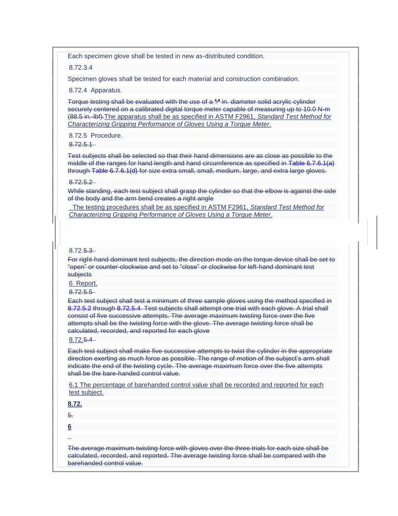
Each specimen glove shall be tested in new as-distributed condition.
8.72.3.4
Specimen gloves shall be tested for each material and construction combination.
8.72.4 Apparatus.
Torque testing shall be evaluated with the use of a 5⁄8 in. diameter solid acrylic cylinder securely centered on a calibrated digital torque meter capable of measuring up to 10.0 N-m (88.5 in.-lbf).The apparatus shall be as specified in ASTM F2961, Standard Test Method for Characterizing Gripping Performance of Gloves Using a Torque Meter.
8.72.5 Procedure.
8.72.5.1
Test subjects shall be selected so that their hand dimensions are as close as possible to the middle of the ranges for hand length and hand circumference as specified in Table 6.7.6.1(a) through Table 6.7.6.1(d) for size extra small, small, medium, large, and extra large gloves.
8.72.5.2
While standing, each test subject shall grasp the cylinder so that the elbow is against the side of the body and the arm bend creates a right angle
The testing procedures shall be as specified in ASTM F2961, Standard Test Method for Characterizing Gripping Performance of Gloves Using a Torque Meter.
8.72.5.3
For right-hand dominant test subjects, the direction mode on the torque device shall be set to “open” or counter-clockwise and set to “close” or clockwise for left-hand dominant test subjects
6 Report.
8.72.5.5
Each test subject shall test a minimum of three sample gloves using the method specified in 8.72.5.2 through 8.72.5.4. Test subjects shall attempt one trial with each glove. A trial shall consist of five successive attempts. The average maximum twisting force over the five attempts shall be the twisting force with the glove. The average twisting force shall be calculated, recorded, and reported for each glove
8.72.5.4
Each test subject shall make five successive attempts to twist the cylinder in the appropriate direction exerting as much force as possible. The range of motion of the subject’s arm shall indicate the end of the twisting cycle. The average maximum force over the five attempts shall be the bare-handed control value.
6.1 The percentage of barehanded control value shall be recorded and reported for each test subject.
8.72.
5.
6
The average maximum twisting force with gloves over the three trials for each size shall be calculated, recorded, and reported. The average twisting force shall be compared with the barehanded control value.

8.72.5.7
The .2 The average percentage of barehanded control value shall be calculated as follows:
where:
DTTg = average twisting force with glove
DTTb = barehanded control value
8.72.6 Report.
The percentage of barehanded control value shall be recorded and reported for each specimen glove size.
8.72.7 Interpretation.
8.72.7.1
The percentage of barehanded control value for size small and size large shall be used to determine pass or fail performance.
8.72.7.2
Failure of either size shall constitute failure of the test.
Statement of Problem and Substantiation for Public Input
See PI 146
Related Public Inputs for This Document
Related Input Relationship
Public Input No. 146-NFPA 1971-2015 [Section No. 2.3.3]
146 is Chapter 2, 147 is Chapter 8
Submitter Information Verification
Submitter Full Name: ROBIN TUTOR
Organization: UL LLC
Street Address:
City:
State:
Zip:
Submittal Date: Mon Jun 29 11:16:16 EDT 2015
Public Input No. 15-NFPA 1971-2013 [ Sections 8.72.5.2, 8.72.5.3, 8.72.5.4 ]
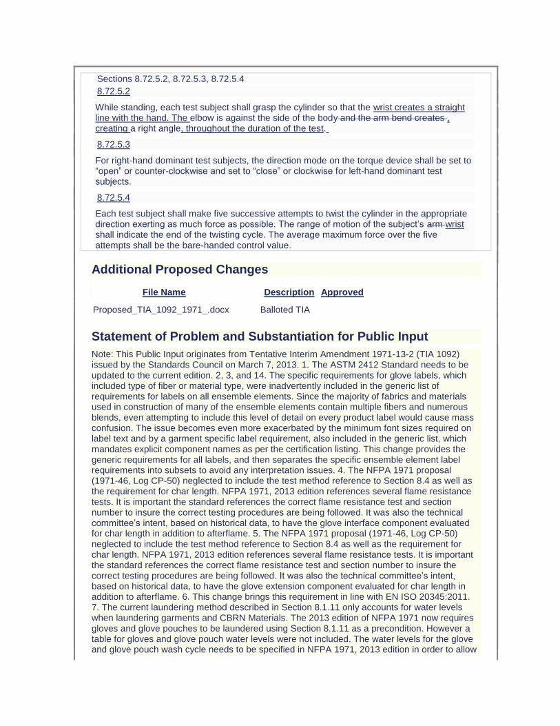
Sections 8.72.5.2, 8.72.5.3, 8.72.5.4
8.72.5.2
While standing, each test subject shall grasp the cylinder so that the wrist creates a straight line with the hand. The elbow is against the side of the body and the arm bend creates , creating a right angle, throughout the duration of the test.
8.72.5.3
For right-hand dominant test subjects, the direction mode on the torque device shall be set to “open” or counter-clockwise and set to “close” or clockwise for left-hand dominant test subjects.
8.72.5.4
Each test subject shall make five successive attempts to twist the cylinder in the appropriate direction exerting as much force as possible. The range of motion of the subject’s arm wrist shall indicate the end of the twisting cycle. The average maximum force over the five attempts shall be the bare-handed control value.
Additional Proposed Changes
File Name Description Approved
Proposed_TIA_1092_1971_.docx Balloted TIA
Statement of Problem and Substantiation for Public Input
Note: This Public Input originates from Tentative Interim Amendment 1971-13-2 (TIA 1092) issued by the Standards Council on March 7, 2013. 1. The ASTM 2412 Standard needs to be updated to the current edition. 2, 3, and 14. The specific requirements for glove labels, which included type of fiber or material type, were inadvertently included in the generic list of requirements for labels on all ensemble elements. Since the majority of fabrics and materials used in construction of many of the ensemble elements contain multiple fibers and numerous blends, even attempting to include this level of detail on every product label would cause mass confusion. The issue becomes even more exacerbated by the minimum font sizes required on label text and by a garment specific label requirement, also included in the generic list, which mandates explicit component names as per the certification listing. This change provides the generic requirements for all labels, and then separates the specific ensemble element label requirements into subsets to avoid any interpretation issues. 4. The NFPA 1971 proposal (1971-46, Log CP-50) neglected to include the test method reference to Section 8.4 as well as the requirement for char length. NFPA 1971, 2013 edition references several flame resistance tests. It is important the standard references the correct flame resistance test and section number to insure the correct testing procedures are being followed. It was also the technical committee’s intent, based on historical data, to have the glove interface component evaluated for char length in addition to afterflame. 5. The NFPA 1971 proposal (1971-46, Log CP-50) neglected to include the test method reference to Section 8.4 as well as the requirement for char length. NFPA 1971, 2013 edition references several flame resistance tests. It is important the standard references the correct flame resistance test and section number to insure the correct testing procedures are being followed. It was also the technical committee’s intent, based on historical data, to have the glove extension component evaluated for char length in addition to afterflame. 6. This change brings this requirement in line with EN ISO 20345:2011. 7. The current laundering method described in Section 8.1.11 only accounts for water levels when laundering garments and CBRN Materials. The 2013 edition of NFPA 1971 now requires gloves and glove pouches to be laundered using Section 8.1.11 as a precondition. However a table for gloves and glove pouch water levels were not included. The water levels for the glove and glove pouch wash cycle needs to be specified in NFPA 1971, 2013 edition in order to allow
for the front load wash machines to be properly programmed at the testing laboratories. The highest water levels currently in the standard were chosen to account for usage of both 35 lb and 50 lb capacity front-loading machines. The higher levels will also accommodate a full load of gloves/glove pouches and eliminate any risk associated with residual detergent. 8, 9, 15 and 16. Some changes made to the way the measurement of hood shrinkage were specified in cleaning shrinkage as part of the NFPA 1971-2013 revision would prevent any hood from being certified to the new requirements. There was also an inconsistency between how hood shrinkage was evaluated for both thermal and cleaning shrinkage for the interpretation of test results that would lead to inconsistent determinations of compliance among testing laboratories. The proposed changes using the same approach established in the 2007 edition of NFPA 1971 for applying cleaning shrinkage criteria while clarifications have been made for interpretation of permitted shrinkage in both cleaning and thermal shrinkage test methods. 10. NFPA 1971, 2013 edition has sections for glove pouch construction, sections 8.1.15 and 8.1.16. Section 8.27.8.2, section for Liquid Penetration Resistance, should reference section 8.1.16 for moisture barrier testing. 11. NFPA 1971, 2013 edition has sections for glove pouch construction, sections 8.1.15 and 8.1.16. Section 8.28.8.2, section for Viral Penetration Resistance, should reference section 8.1.16 for moisture barrier testing. 12. The ISO 13287 standard does not provide criteria for the evaluation of systematic increase or decrease of values. Also, the current calibration language is not clear. 13. The test apparatus will be maxed out if the test subject uses their arm’s range of motion to perform this test. In order to achieve more accurate results it is important the test subject use their wrist’s range of motion to perform this test. Emergency Nature: This TIA seeks to correct errors and omissions that were overlooked during the Fall 2013 revision cycle process of NFPA 1971. Additionally, some parts of this TIA correct circumstances in which the standard could adversely impact a method or product that was inadvertently overlooked in the total revision process.
Submitter Information Verification
Submitter Full Name:
TC on FAE-SPF
Organization: TC on Structural and Proximity Fire Fighting Protective Clothing and Equipment
Street Address:
City:
State:
Zip:
Submittal Date: Fri Aug 09 14:50:32 EDT 2013
Public Input No. 77-NFPA 1971-2015 [ Section No. 8.72.5.7 ]
8.72.5.7
The percentage of barehanded control value shall be calculated as follows:
where: DTTg
Percentage of bare-handed control value = TFg/CVb x 100
Where:
TFg = average twisting force with glove
DTTb
CVb = barehanded control value
Statement of Problem and Substantiation for Public Input
The calculation given does not match the typical format generally used. The information on the left of the = sign should be on the right and the value being obtained should be on the left. In addition, the abbreviations used are those used for dexterity testing rather than for torque testing.
Submitter Information Verification
Submitter Full Name: Michael McKenna
Organization: Michael McKenna & Associates,
Street Address:
City:
State:
Zip:
Submittal Date: Wed Apr 01 14:46:24 EDT 2015
Public Input No. 236-NFPA 1971-2015 [ New Section after 8.74 ]
TITLE OF NEW CONTENT
Add new 8.X Radiant Heat Test 4.
Additional Proposed Changes
File Name Description Approved
New_Radiant_Heat_Resistance_Test_4.docx New Radiant Heat Resistance Test 4
Statement of Problem and Substantiation for Public Input
A new test has been proposed to measuring the thermal insulation for the back of the gloves that is more consistent with the type of exposure that generally occurs for this portion of the gloves (radiant heat) as opposed to conductive heat resistance. The new test is based on use of the same radiant panel used for self-contained breathing apparatus facepieces and utilized a new wetting technique that provides a uniform mist exposure of the thermal barrier (innermost) layer of the glove composite to serve as a worse case wetting condition. The specimen holder, sensor, and data acquisition/data analysis system are similar to the equipment specified in ASTM F1939 (RPP test). The test provided output as the time to a predicted second degree burn injury and an initial performance criterion of greater than 90 seconds has been proposed. The test method and sample conditioning technique are undergoing further validation and a
limited interlaboratory test program is proposed over the fall of 2015 and early spring of 2016. This proposal provides the recommended new glove composite radiant heat test method.
Related Public Inputs for This Document
Related Input Relationship
Public Input No. 231-NFPA 1971-2015 [Section No. 7.7.4] Parent log
Submitter Information Verification
Submitter Full Name: JEFFREY STULL
Organization: INTERNATIONAL PERSONNEL PROTECTION, INC.
Street Address:
City:
State:
Zip:
Submittal Date: Mon Jul 06 13:51:50 EDT 2015
Public Input No. 250-NFPA 1971-2015 [ New Section after 8.74 ]
TITLE OF NEW CONTENT
New Tests for Particulate Barrier Protective Hood Interface Component
8.X Particulate Filtration Efficiency Test.
8.X.1 Application. This test shall apply to materials used in particulate barrier protective
hoods.
8.X.2 Samples.
8.X.2.1 Samples shall be conditioned as specified in 8.1.3.
8.X.2.2 Samples for conditioning shall be 1 m (1 yd) square of material for knit materials
provided in roll form, and 1 m (1 yd) in length for knit materials provided in tubular form.
8.X.3 Specimens. A total of 3 specimens shall be tested.
8.X.4 Procedure. Specimens shall be tested as specified in ASTM F1215, Test Method for
Determining the Initial Efficiency of a Flatsheet Filter Medium in an Airflow Using Latex Spheres, at latex sphere sizes ranging from 0.2 μm to 2.0 μm.
8.X.5 Report. The filtration efficiency of each specimen at each particle size shall be recorded
and reported. The average filtration efficiency of all specimens shall be calculated, recorded, and reported for each particle size tested.
8.X.6 Interpretation. The average filtration efficiency at each particle size shall be used to
determine pass or fail performance.
8.Y Air Permeability Test.
8.Y.1 Application. This test shall apply to materials used in particulate barrier protective
hoods.
8.Y.2 Samples.
8.Y.2.1 Samples shall be conditioned as specified in 8.1.3.
8.Y.2.2 Samples for conditioning shall be 1 m (1 yd) square of material for knit materials
provided in roll form, and 1 m (1 yd) in length for knit materials provided in tubular form.
8.Y.3 Specimens. A total of 3 specimens shall be tested.
8.Y.4 Procedure. Specimens shall be tested as specified in ASTM D737, Standard Test
Method for Air Permeability of Textile Fabrics.
8.Y.5 Report. The air permeability of each specimen shall be recorded and reported. The
average air permeability of all specimens shall be calculated, recorded, and reported.
8.Y.6 Interpretation. The average air permeability shall be used to determine pass or fail
performance.
Statement of Problem and Substantiation for Public Input
Protective hoods currently do not require any form of a barrier layer and the majority of protective hoods in the market place are fabricated of two or more layers of an open knit that readily allows smoke and contaminant particles to pass through the hood materials and deposit on the wearer’s skin. Optional requirements for a hood are proposed that define a barrier that limits the passage of particulates as addressed by both design and performance requirements. The proposed changes in this input provide recommended test methods for an optional particular barrier hood interface component. A white paper on this topic is attached.
Related Public Inputs for This Document
Related Input Relationship
Public Input No. 246-NFPA 1971-2015 [New Section after 1.1.2] Parent Log
Submitter Information Verification
Submitter Full Name: JEFFREY STULL
Organization: INTERNATIONAL PERSONNEL PROTECTION, INC
Street Address:
City:
State:
Zip:
Submittal Date: Mon Jul 06 15:53:17 EDT 2015
Public Input No. 78-NFPA 1971-2015 [ Section No. 8.74.5.21 [Excluding any Sub-Sections] ]
The COV shall be calculated by dividing the standard deviation by the average of three repetitions and multiplying by 100.
Coefficient of variation (COV) = (ς/X avg ) x 100 (tried to delete the document formula, but program would not allow me to do it)
Statement of Problem and Substantiation for Public Input
Previously approved by TC ROP Log CP58. The format given for calculations is confusing. Also, the format does not match that given in ROP 1971-82. The symbol for Standard Deviation given in 8.74.5.21 does not match that given in 8.74.5.21.1.
Submitter Information Verification
Submitter Full Name: Michael McKenna
Organization: Michael McKenna & Associates,
Street Address:
City:
State:
Zip:
Submittal Date: Mon Apr 06 14:11:00 EDT 2015
Public Input No. 183-NFPA 1971-2015 [ Section No. A.4.5.4 ]
A.4.5.4
For example, this situation exists when the product is wholly manufactured and assembled by another entity, or entities, for a separate entity that puts their own name and label on the product, frequently called “private labeling,” and markets and sells the product as their product.
Statement of Problem and Substantiation for Public Input
See PI 178
Related Public Inputs for This Document
Related Input Relationship
Public Input No. 178-NFPA 1971-2015 [Section No. 3.3.76]
Public Input No. 179-NFPA 1971-2015 [New Section after 3.3.76]
Public Input No. 180-NFPA 1971-2015 [Section No. 3.3.116]
Public Input No. 181-NFPA 1971-2015 [Section No. 4.2.9]
Public Input No. 182-NFPA 1971-2015 [Sections 4.5.3, 4.5.4]
Submitter Information Verification
Submitter Full Name: ROBIN TUTOR
Organization: UL LLC
Street Address:
City:
State:
Zip:
Submittal Date: Wed Jul 01 17:03:06 EDT 2015
Public Input No. 195-NFPA 1971-2015 [ Section No. A.5.1.9 ]
A.5.1.9
For example, an additional thermal layer that is used in the majority of the boot should be listed on the label. Zippers, eyelets, and similar items should not be listed. Type of leather does not have to be listed. Trade names could be added if desired.
A.5.1.9 For example, an additional thermal layer that is used in the majority of the boot should
be listed on the label. Zippers, eyelets, and similar items should not be listed. Type of
leather does not have to be listed. Trade names could be added if desired.
Statement of Problem and Substantiation for Public Input
make language consistent.
Submitter Information Verification
Submitter Full Name: MICHAEL MCKENNA
Organization: MICHAEL MCKENNA ASSOCIATES
Street Address:
City:
State:
Zip:
Submittal Date: Thu Jul 02 15:28:51 EDT 2015

Public Input No. 16-NFPA 1971-2013 [ Sections A.5.1.9, A.5.1.10, A.5.1.11 ]
Sections A.5.1.9, A.5.1.10, A.5.1.11
A.5.1.9 7.3
For example, an additional thermal layer that is used in the majority of the boot should be listed on the label. Zippers, eyelets, and similar items should not be listed. Type of leather does not have to be listed. Trade names could be added if desired.
A.5.1.10 7.4
Examples of generic terminology for shell material are thermoplastic, thermoplastic/leather, and fiberglass composite, Kevlar® composite, fiberglass composite/leather.
A.5.1.11 7.5
For example, an additional thermal liner that is used in the entire back of the hand of the glove body should be listed on the label. Elastic and similar materials should not be listed. Trade names could be added if desired.
Additional Proposed Changes
File Name Description Approved
Proposed_TIA_1092_1971_.docx Balloted TIA
Statement of Problem and Substantiation for Public Input
Note: This Public Input originates from Tentative Interim Amendment 1971-13-2 (TIA 1092) issued by the Standards Council on March 7, 2013. 1. The ASTM 2412 Standard needs to be updated to the current edition. 2, 3, and 14. The specific requirements for glove labels, which included type of fiber or material type, were inadvertently included in the generic list of requirements for labels on all ensemble elements. Since the majority of fabrics and materials used in construction of many of the ensemble elements contain multiple fibers and numerous blends, even attempting to include this level of detail on every product label would cause mass confusion. The issue becomes even more exacerbated by the minimum font sizes required on label text and by a garment specific label requirement, also included in the generic list, which mandates explicit component names as per the certification listing. This change provides the generic requirements for all labels, and then separates the specific ensemble element label requirements into subsets to avoid any interpretation issues. 4. The NFPA 1971 proposal (1971-46, Log CP-50) neglected to include the test method reference to Section 8.4 as well as the requirement for char length. NFPA 1971, 2013 edition references several flame resistance tests. It is important the standard references the correct flame resistance test and section number to insure the correct testing procedures are being followed. It was also the technical committee’s intent, based on historical data, to have the glove interface component evaluated for char length in addition to afterflame. 5. The NFPA 1971 proposal (1971-46, Log CP-50) neglected to include the test method reference to Section 8.4 as well as the requirement for char length. NFPA 1971, 2013 edition references several flame resistance tests. It is important the standard references the correct flame resistance test and section number to insure the correct testing procedures are being followed. It was also the technical committee’s intent,
based on historical data, to have the glove extension component evaluated for char length in addition to afterflame. 6. This change brings this requirement in line with EN ISO 20345:2011. 7. The current laundering method described in Section 8.1.11 only accounts for water levels when laundering garments and CBRN Materials. The 2013 edition of NFPA 1971 now requires gloves and glove pouches to be laundered using Section 8.1.11 as a precondition. However a table for gloves and glove pouch water levels were not included. The water levels for the glove and glove pouch wash cycle needs to be specified in NFPA 1971, 2013 edition in order to allow for the front load wash machines to be properly programmed at the testing laboratories. The highest water levels currently in the standard were chosen to account for usage of both 35 lb and 50 lb capacity front-loading machines. The higher levels will also accommodate a full load of gloves/glove pouches and eliminate any risk associated with residual detergent. 8, 9, 15 and 16. Some changes made to the way the measurement of hood shrinkage were specified in cleaning shrinkage as part of the NFPA 1971-2013 revision would prevent any hood from being certified to the new requirements. There was also an inconsistency between how hood shrinkage was evaluated for both thermal and cleaning shrinkage for the interpretation of test results that would lead to inconsistent determinations of compliance among testing laboratories. The proposed changes using the same approach established in the 2007 edition of NFPA 1971 for applying cleaning shrinkage criteria while clarifications have been made for interpretation of permitted shrinkage in both cleaning and thermal shrinkage test methods. 10. NFPA 1971, 2013 edition has sections for glove pouch construction, sections 8.1.15 and 8.1.16. Section 8.27.8.2, section for Liquid Penetration Resistance, should reference section 8.1.16 for moisture barrier testing. 11. NFPA 1971, 2013 edition has sections for glove pouch construction, sections 8.1.15 and 8.1.16. Section 8.28.8.2, section for Viral Penetration Resistance, should reference section 8.1.16 for moisture barrier testing. 12. The ISO 13287 standard does not provide criteria for the evaluation of systematic increase or decrease of values. Also, the current calibration language is not clear. 13. The test apparatus will be maxed out if the test subject uses their arm’s range of motion to perform this test. In order to achieve more accurate results it is important the test subject use their wrist’s range of motion to perform this test. Emergency Nature: This TIA seeks to correct errors and omissions that were overlooked during the Fall 2013 revision cycle process of NFPA 1971. Additionally, some parts of this TIA correct circumstances in which the standard could adversely impact a method or product that was inadvertently overlooked in the total revision process.
Submitter Information Verification
Submitter Full Name:
TC on FAE-SPF
Organization: TC on Structural and Proximity Fire Fighting Protective Clothing and Equipment
Street Address:
City:
State:
Zip:
Submittal Date: Fri Aug 09 15:05:16 EDT 2013
Public Input No. 196-NFPA 1971-2015 [ Section No. A.5.1.10 ]
A.5.1.10
Examples of generic terminology for shell material are thermoplastic, thermoplastic/leather, and fiberglass composite, Kevlar® composite, fiberglass composite/leather.
A.5.1.10 Examples of generic terminology for shell material are thermoplastic, thermoplastic/leather, and fiberglass composite, Kevlar® composite, fiberglass composite/leather.
Statement of Problem and Substantiation for Public Input
make the language consistent.
Submitter Information Verification
Submitter Full Name: MICHAEL MCKENNA
Organization: MICHAEL MCKENNA ASSOCIATES
Street Address:
City:
State:
Zip:
Submittal Date: Thu Jul 02 15:29:49 EDT 2015
Public Input No. 197-NFPA 1971-2015 [ Section No. A.5.1.11 ]
A.5.1.11
For example, an additional thermal liner that is used in the entire back of the hand of the glove body should be listed on the label. Elastic and similar materials should not be listed. Trade names could be added if desired.
A.5.1.11 For example, an additional thermal liner that is used in the entire back of the hand of
the glove body should be listed on the label. Elastic and similar materials should not be
listed. Trade names could be added if desired.
Statement of Problem and Substantiation for Public Input
make language consistent.
Submitter Information Verification
Submitter Full Name: MICHAEL MCKENNA
Organization: MICHAEL MCKENNA ASSOCIATES
Street Address:
City:
State:
Zip:
Submittal Date: Thu Jul 02 15:32:35 EDT 2015
Public Input No. 189-NFPA 1971-2015 [ New Section after A.6.2.4 ]
A.6.4.8 Examples of items include, but are not limited to: (1) front holders for helmet identification shields, (2) supplemental face shields and (3) other eye/face protection where goggles are provided with the helmet as the required face shield/google component as identified in 6.5.2.
Statement of Problem and Substantiation for Public Input
This is being submitted as TIA language that was approved by the TC and CC but has not been reviewed/approved by the Standards Council.
Related Public Inputs for This Document
Related Input Relationship
Public Input No. 188-NFPA 1971-2015 [New Section after 6.4.7]
Submitter Information Verification
Submitter Full Name: TRICIA HOCK
Organization: SAFETY EQUIPMENT INSTITUTE SE
Street Address:
City:
State:
Zip:
Submittal Date: Thu Jul 02 13:09:51 EDT 2015
Public Input No. 137-NFPA 1971-2015 [ Section No. A.6.5.2 ]
A.6.5.2
Many helmet designs expose the faceshield/goggle component(s) to abrasion, heat, flame, and particulate contamination. Purchasers might wish to specify a means of protecting the
component(s). This could include, but not be limited to, faceshield/goggle components that retract inside the helmet, and coverings for the component(s) that are inherently resistant to the fire fighting environment. Fire departments should consider the health risks associated with contaminated goggles coming in direct contact with the wearer's face. Goggles do not have to be attached to the helmet.
Statement of Problem and Substantiation for Public Input
If other inputs related to faceshields/goggles are accepted. This annex is not needed. The intent of this submittal is to remove faceshield/goggle/flip-down components from being externally attached to the helmet. Fire fighters are claiming neck and back injuries due to the “unbalanced” design of helmets. This has resulted in lawsuits against helmet manufacturers and dealers for neck and back injuries. Removal of externally mounted faceshield/goggle/flip-down components will minimize the “unbalance” issue. Faceshield/goggle/flip-down components, when externally mounted, provide additional safety and health hazards to fire fighters. These components are exposed to heat and physical damage during fire fighting and exposed to physical damage during other times. This causes the visibility through the components to be greatly compromised, often making visibility impossible. Goggles are exposed to the many carcinogens found in fire fighting and pose a health hazard when worn. Consequently, these components are almost never deployed and in many cases are removed from the helmet by the fire fighter. Most importantly, during structural fire fighting, face and eye protection should be provided by the SCBA mask, not a faceshield/goggle component. Faceshield/goggle components that are integrated into the helmet so they retract beneath the shell, when in the stowed position, should be allowed.
Submitter Information Verification
Submitter Full Name: ROBERT TUTTEROW
Organization: FIRE INDUSTRY EQUIPMENT RESEAR
Street Address:
City:
State:
Zip:
Submittal Date: Sat Jun 27 15:26:28 EDT 2015
Public Input No. 255-NFPA 1971-2015 [ New Section after A.7.20.1.1 ]
TITLE OF NEW CONTENT: Appendix section recommeding (but not requiring) finger lengths in addition to D2 Index Finger
The proposed sizing system in Section 6.7.6 requires D2 Index Finger lengths for each size. For informational purposes, the following data is presented from "Hand Anthropometry of US Army Personnel" by Thomas M. Greiner 1991 as guidance for the other fingers.
Means Means
Finger Females (mm) Females: Ratio compared to D2 Males (mm) Males: Ratio compared to D2
D1 Thumb 63.5 0.91 69.70 0.93
D2 Index 69.6 1.00 75.30 1.00
D3 Middle 77.2 1.11 83.80 1.11
D4 Ring 72.2 1.04 79.20 1.05
D5 Little 58.3 0.84 64.70 0.86
After selecting a size from section 6.7.6., the ratios from this table can be used for guidance on the other finger lengths. Refer to original study for a complete discussion on the variance for each of these measurements.
Statement of Problem and Substantiation for Public Input
The proposed sizing system requires D2 Index finger length for each size. However, it does not specify the finger lengths of every size. The purpose of this section is to recommend other finger lengths and to direct end-users/manufacturers to the original study on which NFPA 1971 sizing systems have been based for last two decades.
Related Public Inputs for This Document
Related Input Relationship
Public Input No. 127-NFPA 1971-2015 [Section No. 6.7.6 [Excluding any Sub-Sections]]
Recommends (but does not specify) other finger lengths
Submitter Information Verification
Submitter Full Name: Mark Williams
Organization: W.L. Gore & Associates, Inc.
Affilliation: W.L. Gore & Associates, Inc.
Street Address:
City:
State:
Zip:
Submittal Date: Mon Jul 06 16:30:06 EDT 2015
Public Input No. 18-NFPA 1971-2013 [ New Section after A.8.6.8.6 ]
A.8.6.16.13 This average should be based on a total of 12 values of percentage shrinkage
with four values per specimen.
A.8.6.16.14 This average should be based on a total of 9 values of percentage shrinkage
with three values per specimen.
Additional Proposed Changes
File Name Description Approved

Proposed_TIA_1092_1971_.docx Balloted TIA
Statement of Problem and Substantiation for Public Input
Note: This Public Input originates from Tentative Interim Amendment 1971-13-2 (TIA 1092) issued by the Standards Council on March 7, 2013. 1. The ASTM 2412 Standard needs to be updated to the current edition. 2, 3, and 14. The specific requirements for glove labels, which included type of fiber or material type, were inadvertently included in the generic list of requirements for labels on all ensemble elements. Since the majority of fabrics and materials used in construction of many of the ensemble elements contain multiple fibers and numerous blends, even attempting to include this level of detail on every product label would cause mass confusion. The issue becomes even more exacerbated by the minimum font sizes required on label text and by a garment specific label requirement, also included in the generic list, which mandates explicit component names as per the certification listing. This change provides the generic requirements for all labels, and then separates the specific ensemble element label requirements into subsets to avoid any interpretation issues. 4. The NFPA 1971 proposal (1971-46, Log CP-50) neglected to include the test method reference to Section 8.4 as well as the requirement for char length. NFPA 1971, 2013 edition references several flame resistance tests. It is important the standard references the correct flame resistance test and section number to insure the correct testing procedures are being followed. It was also the technical committee’s intent, based on historical data, to have the glove interface component evaluated for char length in addition to afterflame. 5. The NFPA 1971 proposal (1971-46, Log CP-50) neglected to include the test method reference to Section 8.4 as well as the requirement for char length. NFPA 1971, 2013 edition references several flame resistance tests. It is important the standard references the correct flame resistance test and section number to insure the correct testing procedures are being followed. It was also the technical committee’s intent, based on historical data, to have the glove extension component evaluated for char length in addition to afterflame. 6. This change brings this requirement in line with EN ISO 20345:2011. 7. The current laundering method described in Section 8.1.11 only accounts for water levels when laundering garments and CBRN Materials. The 2013 edition of NFPA 1971 now requires gloves and glove pouches to be laundered using Section 8.1.11 as a precondition. However a table for gloves and glove pouch water levels were not included. The water levels for the glove and glove pouch wash cycle needs to be specified in NFPA 1971, 2013 edition in order to allow for the front load wash machines to be properly programmed at the testing laboratories. The highest water levels currently in the standard were chosen to account for usage of both 35 lb and 50 lb capacity front-loading machines. The higher levels will also accommodate a full load of gloves/glove pouches and eliminate any risk associated with residual detergent. 8, 9, 15 and 16. Some changes made to the way the measurement of hood shrinkage were specified in cleaning shrinkage as part of the NFPA 1971-2013 revision would prevent any hood from being certified to the new requirements. There was also an inconsistency between how hood shrinkage was evaluated for both thermal and cleaning shrinkage for the interpretation of test results that would lead to inconsistent determinations of compliance among testing laboratories. The proposed changes using the same approach established in the 2007 edition of NFPA 1971 for applying cleaning shrinkage criteria while clarifications have been made for interpretation of permitted shrinkage in both cleaning and thermal shrinkage test methods. 10. NFPA 1971, 2013 edition has sections for glove pouch construction, sections 8.1.15 and 8.1.16. Section 8.27.8.2, section for Liquid Penetration Resistance, should reference section 8.1.16 for moisture barrier testing. 11. NFPA 1971, 2013 edition has sections for glove pouch construction, sections 8.1.15 and 8.1.16. Section 8.28.8.2, section for Viral Penetration Resistance, should reference section 8.1.16 for moisture barrier testing. 12. The ISO 13287 standard does not provide criteria for the evaluation of systematic increase or decrease of values. Also, the current calibration language is not clear. 13. The test apparatus will be maxed out if the test subject uses their arm’s range of motion to perform this test. In order to achieve more accurate results it is important the test subject use their wrist’s range of motion to perform this test. Emergency Nature: This TIA seeks to correct errors and omissions that were
overlooked during the Fall 2013 revision cycle process of NFPA 1971. Additionally, some parts of this TIA correct circumstances in which the standard could adversely impact a method or product that was inadvertently overlooked in the total revision process.
Submitter Information Verification
Submitter Full Name:
TC on FAE-SPF
Organization: TC on Structural and Proximity Fire Fighting Protective Clothing and Equipment
Street Address:
City:
State:
Zip:
Submittal Date: Fri Aug 09 15:08:48 EDT 2013
Public Input No. 90-NFPA 1971-2015 [ Section No. A.8.15.4.9 ]
A.8.15.4.9
Equipment Guidelines. The instrumentation should be allowed to warm up until it stabilizes. No simple means exists to calibrate the impact system required by this standard. Nevertheless, calibration is necessary. The equipment should be checked for repeatability before and after each series of tests by impacting a standardized elastomeric shock pad. A minimum of three such impacts are recorded before and after testing. If the post-test average readings of the three impacts differs from the pre-test average by more than 5 percent, the entire test series is discarded.
The impact tester should have a guide rail at least 3 m (9.8 ft) in height and capable of producing impact velocities required by this standard. Test anvils, headforms, transducers, and so forth, mounted to the base should be attached so that no energy is absorbed through deflections and the base should be at least 25 mm (1.0 in.) thick steel. Guide mechanisms that slide on the rail should have recirculating ball bearings to minimize friction. The impactor guide mechanism should contain an automatic brake to prevent second impacts (bounding). A velocity detector is required to assure proper drop heights. The position of said detector should be adjustable so that the speed of impact is measured no more than 20 mm (0.79 in.) from the point of impact. A detector flat attached to the guide mechanism that passes through or by the detector should not be greater than 26 mm (1.02 in.) in height. The detector should be capable of resolving velocities of 0.01 millisecond increments. Magnetic detector systems can also be used if equivalency is established. An electronic timer is used to determine the speed at which the flag traverses the detector. The load cell should conform to the following characteristics:
(1) Size: 75 mm (3.0 in.) diameter min
(2) Measuring range: 0–5000 N (0–1124 lbf) min
(3) Resolution: 45 N (10.1 lbf) max
(4) Accuracy, linearity: ±2.5% full-scale max
(5) Rigidity: 4.5 × 10°N10^9 N/m (2.6 × 10 7 lbf/in.) min
(6) Transverse sensitivity: 3.0% max
The load cell/headform mounting system should not have a resonant frequency less than 5 kHz, and the frequency response of the system should be in compliance with SAE Recommended Practice J211b, Channel Class 1000.
It is recommended that the load cell output be recorded with a storage oscilloscope, transient recorder, or similar device designed to store maximum readings. However, maximum for readings can be obtained using a peak-indicating meter designed to store only a maximum reading. The frequency response of peak-indicating meters should at least meet the requirements of SAE Recommended Practice J211b, Channel Class 1000. Resolution should be 45 N (10.1 lbf) max with rise time capability less than 0.01 milliseconds.
Calibration. Strain gauge-type load cells can generally be calibrated statically by applying a known dead weight to the top of the load cell and checking the output signal. This works well with an oscilloscope or voltmeter. However, transient vibrations tend to create a problem when using peak-indicating meters, and thus the load must be applied and/or removed with extreme care. Furthermore, static calibration does not take into account the dynamic response of the measuring system. Dynamic calibration is recommended but requires a calibrated reference accelerometer and a calibrating medium (shock pad). The reference accelerometer should have the following characteristics:
(1) Measuring range: 0–400 Gs min
(2) Resolution: 1.0 G max
(3) Accuracy, linearity: 1.0% full-scale max
(4) Transverse sensitivity 3.0% max
(5) Resonant frequency: 20 kHz min
(6) Frequency response: ±0.5 db @ 0.1 hz–2.0 kHz
(7) Repeatability/stability: 1.0% full-scale max
The calibrating medium should have the following characteristics:
(1) Material: Elastomer (high resilience and low hysteresis)
(2) Durometer: 50–60 Shore A
(3) Thickness: 25 mm (1.0 in.) min
(4) Size: 100 m (4.0 in.) diameter min
The accelerometer is mounted on top of the 3.6 kg (8.0 lb) impactor along its vertical axis (±2.5 degrees of true vertical) according to the manufacturer's instructions. A dual channel storage oscilloscope is recommended for making simultaneous records of both accelerometer and load cell outputs. Both accelerometer and oscilloscope should be in recent calibration.
Force Measuring System Calibration Procedure. Remove headform from load cell and mount the calibrating medium to the top of the load cell. All electronic systems should be turned on and allow to stabilize. The impactor, with accelerometer attached, should be dropped onto the calibrating medium from a height that yields a maximum acceleration reading of 100 Gs ± 10 Gs. Outputs of both accelerometer and load cell should be recorded. The two maximum
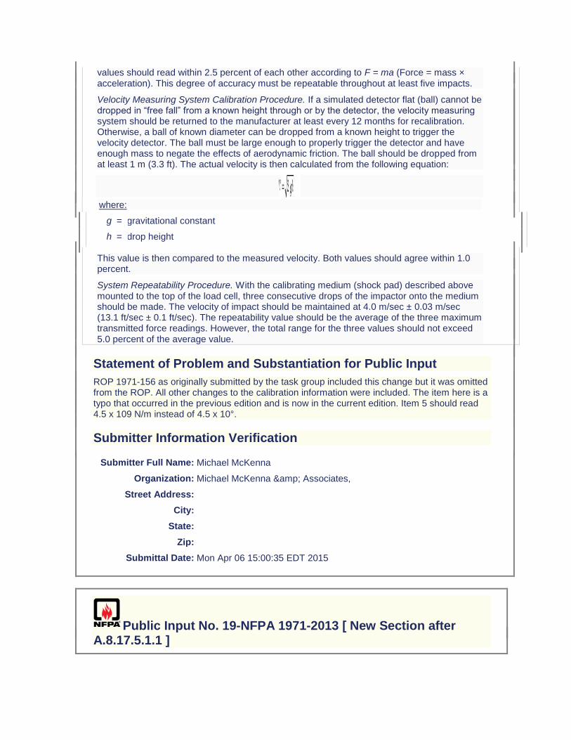
values should read within 2.5 percent of each other according to F = ma (Force = mass × acceleration). This degree of accuracy must be repeatable throughout at least five impacts.
Velocity Measuring System Calibration Procedure. If a simulated detector flat (ball) cannot be dropped in “free fall” from a known height through or by the detector, the velocity measuring system should be returned to the manufacturer at least every 12 months for recalibration. Otherwise, a ball of known diameter can be dropped from a known height to trigger the velocity detector. The ball must be large enough to properly trigger the detector and have enough mass to negate the effects of aerodynamic friction. The ball should be dropped from at least 1 m (3.3 ft). The actual velocity is then calculated from the following equation:
where:
g = gravitational constant
h = drop height
This value is then compared to the measured velocity. Both values should agree within 1.0 percent.
System Repeatability Procedure. With the calibrating medium (shock pad) described above mounted to the top of the load cell, three consecutive drops of the impactor onto the medium should be made. The velocity of impact should be maintained at 4.0 m/sec ± 0.03 m/sec (13.1 ft/sec ± 0.1 ft/sec). The repeatability value should be the average of the three maximum transmitted force readings. However, the total range for the three values should not exceed 5.0 percent of the average value.
Statement of Problem and Substantiation for Public Input
ROP 1971-156 as originally submitted by the task group included this change but it was omitted from the ROP. All other changes to the calibration information were included. The item here is a typo that occurred in the previous edition and is now in the current edition. Item 5 should read 4.5 x 10⁹ N/m instead of 4.5 x 10°.
Submitter Information Verification
Submitter Full Name: Michael McKenna
Organization: Michael McKenna & Associates,
Street Address:
City:
State:
Zip:
Submittal Date: Mon Apr 06 15:00:35 EDT 2015
Public Input No. 19-NFPA 1971-2013 [ New Section after A.8.17.5.1.1 ]
A.8.24.9.10 This average should be based on a total of 12 values of percentage shrinkage
with four values per specimen.
A.8.24.9.11 This average should be based on a total of 9 values of percentage shrinkage
with three values per specimen.
Additional Proposed Changes
File Name Description Approved
Proposed_TIA_1092_1971_.docx Balloted TIA
Statement of Problem and Substantiation for Public Input
Note: This Public Input originates from Tentative Interim Amendment 1971-13-2 (TIA 1092) issued by the Standards Council on March 7, 2013. 1. The ASTM 2412 Standard needs to be updated to the current edition. 2, 3, and 14. The specific requirements for glove labels, which included type of fiber or material type, were inadvertently included in the generic list of requirements for labels on all ensemble elements. Since the majority of fabrics and materials used in construction of many of the ensemble elements contain multiple fibers and numerous blends, even attempting to include this level of detail on every product label would cause mass confusion. The issue becomes even more exacerbated by the minimum font sizes required on label text and by a garment specific label requirement, also included in the generic list, which mandates explicit component names as per the certification listing. This change provides the generic requirements for all labels, and then separates the specific ensemble element label requirements into subsets to avoid any interpretation issues. 4. The NFPA 1971 proposal (1971-46, Log CP-50) neglected to include the test method reference to Section 8.4 as well as the requirement for char length. NFPA 1971, 2013 edition references several flame resistance tests. It is important the standard references the correct flame resistance test and section number to insure the correct testing procedures are being followed. It was also the technical committee’s intent, based on historical data, to have the glove interface component evaluated for char length in addition to afterflame. 5. The NFPA 1971 proposal (1971-46, Log CP-50) neglected to include the test method reference to Section 8.4 as well as the requirement for char length. NFPA 1971, 2013 edition references several flame resistance tests. It is important the standard references the correct flame resistance test and section number to insure the correct testing procedures are being followed. It was also the technical committee’s intent, based on historical data, to have the glove extension component evaluated for char length in addition to afterflame. 6. This change brings this requirement in line with EN ISO 20345:2011. 7. The current laundering method described in Section 8.1.11 only accounts for water levels when laundering garments and CBRN Materials. The 2013 edition of NFPA 1971 now requires gloves and glove pouches to be laundered using Section 8.1.11 as a precondition. However a table for gloves and glove pouch water levels were not included. The water levels for the glove and glove pouch wash cycle needs to be specified in NFPA 1971, 2013 edition in order to allow for the front load wash machines to be properly programmed at the testing laboratories. The highest water levels currently in the standard were chosen to account for usage of both 35 lb and 50 lb capacity front-loading machines. The higher levels will also accommodate a full load of gloves/glove pouches and eliminate any risk associated with residual detergent. 8, 9, 15 and 16. Some changes made to the way the measurement of hood shrinkage were specified in cleaning shrinkage as part of the NFPA 1971-2013 revision would prevent any hood from being certified to the new requirements. There was also an inconsistency between how hood shrinkage was evaluated for both thermal and cleaning shrinkage for the interpretation of test results that would lead to inconsistent determinations of compliance among testing laboratories. The proposed changes using the same approach established in the 2007 edition of NFPA 1971 for applying cleaning shrinkage criteria while clarifications have been made for interpretation of permitted shrinkage in both cleaning and thermal shrinkage test methods. 10. NFPA 1971,
2013 edition has sections for glove pouch construction, sections 8.1.15 and 8.1.16. Section 8.27.8.2, section for Liquid Penetration Resistance, should reference section 8.1.16 for moisture barrier testing. 11. NFPA 1971, 2013 edition has sections for glove pouch construction, sections 8.1.15 and 8.1.16. Section 8.28.8.2, section for Viral Penetration Resistance, should reference section 8.1.16 for moisture barrier testing. 12. The ISO 13287 standard does not provide criteria for the evaluation of systematic increase or decrease of values. Also, the current calibration language is not clear. 13. The test apparatus will be maxed out if the test subject uses their arm’s range of motion to perform this test. In order to achieve more accurate results it is important the test subject use their wrist’s range of motion to perform this test. Emergency Nature: This TIA seeks to correct errors and omissions that were overlooked during the Fall 2013 revision cycle process of NFPA 1971. Additionally, some parts of this TIA correct circumstances in which the standard could adversely impact a method or product that was inadvertently overlooked in the total revision process.
Submitter Information Verification
Submitter Full Name:
TC on FAE-SPF
Organization: TC on Structural and Proximity Fire Fighting Protective Clothing and Equipment
Street Address:
City:
State:
Zip:
Submittal Date: Fri Aug 09 15:11:27 EDT 2013
Public Input No. 165-NFPA 1971-2015 [ Section No. A.8.40.4 ]
A.8.40.4
However, if experience shows that the friction properties of the test floor are not strongly influenced by repeated testing, calibration intervals could be extended.
Statement of Problem and Substantiation for Public Input
See PI 162
Related Public Inputs for This Document
Related Input Relationship
Public Input No. 162-NFPA 1971-2015 [Section No. 2.3.3] Ch 2 ASTM
Public Input No. 163-NFPA 1971-2015 [Section No. 2.3.9] Ch 2 ISO
Public Input No. 164-NFPA 1971-2015 [Section No. 8.40] Ch 8
Submitter Information Verification
Submitter Full Name: ROBIN TUTOR
Organization: UL LLC
Street Address:
City:
State:
Zip:
Submittal Date: Mon Jun 29 16:25:06 EDT 2015
Public Input No. 40-NFPA 1971-2014 [ Chapter B ]
Annex B Informational References
B.1 Referenced Publications.
The documents or portions thereof listed in this annex are referenced within the informational sections of this standard and are not part of the requirements of this document unless also listed in Chapter 2 for other reasons.
B.1.1 NFPA Publications.
National Fire Protection Association, 1 Batterymarch Park, Quincy, MA 02169-7471.
NFPA 1500, Standard on Fire Department Occupational Safety and Health Program, 2013 edition.
NFPA 1851, Standard on Selection, Care, and Maintenance of Protective Ensembles for Structural Fire Fighting and Proximity Fire Fighting, 2008 edition 2014.
NFPA 1973, Standard on Gloves for Structural Fire Fighting, 1983 edition.
NFPA 1973, Standard on Gloves for Structural Fire Fighting, 1988 edition.
NFPA 1973, Standard on Gloves for Structural Fire Fighting, 1993 edition.
NFPA 1992, Standard on Liquid Splash-Protective Ensembles and Clothing for Hazardous Materials Emergencies, 2012 edition 2017.
B.1.2 Other Publications.
B.1.2.1 ANSI Publications.
American National Standards Institute, Inc., 25 West 43rd Street, 4th Floor, New York, NY 10036.
ANSI/ISEA 107, Hand Protection Selection Criteria, 2011 American National Standard for High-Visibility Safety Apperal and Headwear, 2010.
ANSI/ISEA 207, High Visibility Public Safety Vests, 2011.
B.1.2.2 ASTM Publications.
ASTM International, 100 Barr Harbor Drive, P.O. Box C700, West Conshohocken, PA 19428-2959.
ASTM D 1003, Standard Test Method for Haze and Luminous Transmittance of Transparent Plastics, 2000 2013.
ASTM F 1868, Standard Test Method for Thermal and Evaporative Resistance of Clothing Materials Using a Sweating Hot Plate, 2002 2014.
Stull, J. O. and R. M. Duffy, “Field Evaluation of Protective Clothing Effects on Fire Fighter Physiology: Predictive Capability of the Total Heat Loss Test.” In Performance of Protective Clothing: Issues and Priorities for the 21st Century [ASTM STP 1386], ed. C. N. Nelson and N. W. Henry, 481–503, West Conshohocken, PA: American Society for Testing and Materials.
B.1.2.3 Federal Highway Administration Publications.
1200 New Jersey Avenue, SE, Washington, DC 20590.
Manual on Uniform Traffic Control Devices (MUTCD), 2009. http://mutcd.fhwa.dot.gov
B.1.2.4 NIOSH Publications.
National Institute for Occupational Safety and Health, Centers for Disease Control and Prevention, 1600 Clifton Road, Atlanta, GA 30333.
NIOSH 77-134-A, The Development of Criteria for Firefighters' Gloves, vol. 1, 1976.
NIOSH 77-134-B, Glove Requirements, vol. 2, 1976.
B.1.2.5 SAE Publications.
Society of Automotive EngineersSAE International, 400 Commonwealth Drive, Warrendale,
PA 15096.
SAE Recommended Practice J211b, Channel Class 1000.
B.1.2.6 U.S. Government Publications.
U.S. Government Printing Office, Washington, DC 20402.
Title 29, Code of Federal Regulations, Part 7, Subpart C, 1 April 1997.
Title 42, Code of Federal Regulations, Part 84, Subpart E.
B.1.2.7 U.S. Military Publications.
U.S. Army Developmental Test Command (DTC), ATTN: CSTE-DTC-TT-S, Aberdeen Proving Ground, MD 21005–5055.
NATO Document No. 1268015, AEP-52, “Assessment of the Effect Levels of Classical Chemical Warfare Agents Applied to the Skin to be Used in the Design of Protective Equipment,” 2003.
Test Operations Procedure (TOP 8-2-501), Permeation and Penetration of Air-Permeable, Semipermeable, and Impermeable Materials with Chemical Agents or Simulants, 1997.
B.1.2.8 Other Publications.
Simms, D. L. and P. L. Hinkley, Part 10, The Effect of Water on Clothing, Suitable for Clothing Aircraft Fire Crash Rescue Workers, F. R. Note 366, Fire Research Station, Boreham Wood, Herts, England, 1959.
Grotte, J. H. and Yang, L. I., “Report of the Workshop on Chemical Agent Toxicity for Acute Effects,” IDA Document D-2176, Institute for Defense Analysis, Alexandria, VA, May 1998
B.2 Informational References. (Reserved)
B.3 References for Extracts in Informational Sections. (Reserved)
Statement of Problem and Substantiation for Public Input
Referenced current editions.

Related Public Inputs for This Document
Related Input Relationship
Public Input No. 39-NFPA 1971-2014 [Chapter 2] Referencece current editions.
Submitter Information Verification
Submitter Full Name: Aaron Adamczyk
Organization: [ Not Specified ]
Street Address:
City:
State:
Zip:
Submittal Date: Sat Jun 28 21:15:54 EDT 2014
Public Input No. 245-NFPA 1971-2015 [ New Section after B.3 ]
TITLE OF NEW CONTENT
Type your content here ...
Additional Proposed Changes
File Name Description Approved
NFPA_1971_Annex_C.docx
Statement of Problem and Substantiation for Public Input
General descriptions for the different performance criteria and related test methods used for qualifying structural fire fighting protective ensemble elements have been developed to enable fire fighters, specifiers, and other individuals to better understand how ensemble elements are tested and provide information on what the test results mean. This non-mandatory information is intended to help improve awareness for the use of performance criteria and test methods within the standard.
Submitter Information Verification
Submitter Full Name: ROBERT TUTTEROW
Organization: FIRE INDUSTRY EQUIPMENT RESEAR
Street Address:
City:
State:

Zip:
Submittal Date: Mon Jul 06 14:27:38 EDT 2015