technical catalogue system pro m modular devices - abb … · unifix is the abb cabling system...
TRANSCRIPT
2CSC440001D0201
System pro MProtection, command,load management and measurementmodular devices
Technical catalogue
2CS
C44
0001
D02
01 -
Feb
brai
o ’0
4P
rinte
d in
Ital
y10
.000
- C
AL
Sys
tem
pro
M P
rote
ctio
n, c
omm
and,
load
man
agem
ent a
nd m
easu
rem
ent m
odul
ar d
e vic
es
In consideration of modifications to Standards and materials,the characteristics and overall dimensions indicated in thiscatalogue may be considered binding only following confirmationby ABB SACE
ABB SACE S.p.AAn ABB Group company
Line Protection DevicesViale dell’Industria, 1820010 Vittuone (MI) - ItalyTel.: +39.02.9034.1 - Telefax: +39.02.9034.7609
http://www.abb.com
0 Cop 12-05-2004, 10:531
1
1
2
3
SUMMARY
4
Protection, command, load management andmeasurement modular devices
Technical details
Application sheets
Overall dimensions

0/2 ABB SACE
ABB SACE is one of the forerunners among the companies in the Group in dedicatingconsiderable resources towards reaching its objectives of sustainable development andenvironmental protection. This is confirmed by the fact that all the company manufactu-ring sites have been awarded ISO 9001 quality certification and most of them have alsobeen awarded ISO 14001 environmental management system certification. The plantsin Frosinone and Patrica have also been awarded the Quality, Environment and SafetyIntegrated System certification and are certified in compliance with the BS 8800 Stan-dards for health and safety in the workplace.
ABB SACE is actively involved in continuing the policy of improving environmental man-agement by rationalizing the consumption of raw materials and energy, preventing pol-lution, respecting water and air, reducing noise levels to a minimum, reducing wastefrom production processes and carrying out periodic environmental checks at the mainsuppliers’ premises.By using analysis tools such as LCA (Life Cycle Assessment), from the initial designstages ABB SACE assesses and improves the environmental performance of its pro-ducts throughout their entire life cycle in order to guarantee maximum efficiency in tech-nical and energy performance during operation, control and reduce environmental im-pact in the manufacturing stage and define end-of-life procedures.
All these goals and activities are the result of a far-sightedness in adoptingecological policies and methods of reducing environmental impact and, here too,ABB SACE is, as already seen in the quality of its products, a leader on the Italiancompany scene.
ABB SACEand its commitment to protecting the environment

0/3ABB SACEPlant at Pomezia - Rome
0/4 ABB SACE
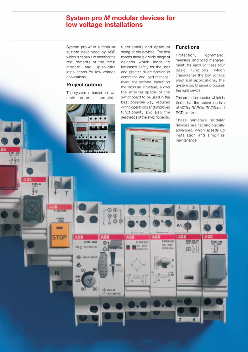
System pro M modular devices forlow voltage installations
Functions
Protection, command,measure and load manage-ment: for each of these fourbasic functions whichcharacterize the low voltageelectrical applications, theSystem pro M series proposesthe right device.
The protection sector which isthe basis of the system consistsof MCBs, RCBOs, RCCBs andRCD blocks.
These miniature modulardevices are technologicallyadvanced, which speeds upinstallation and simplif iesmaintenance.
System pro M is a modularsystem developed by ABBwhich is capable of meeting therequirements of the mostmodern and up-to-dateinstallations for low voltageapplications.
Project criteria
The system is based on twomain criteria: complete
functionality and optimumsizing of the devices. The firstmeans there is a wide range ofdevices which leads toincreased safety for the userand greater diversification incommand and load manage-ment; the second, based onthe modular structure, allowsthe internal space of theswitchboard to be used in thebest possible way, reduceswiring operations and improvesfunctionality and also theaesthetics of the switchboards.
0/5ABB SACE
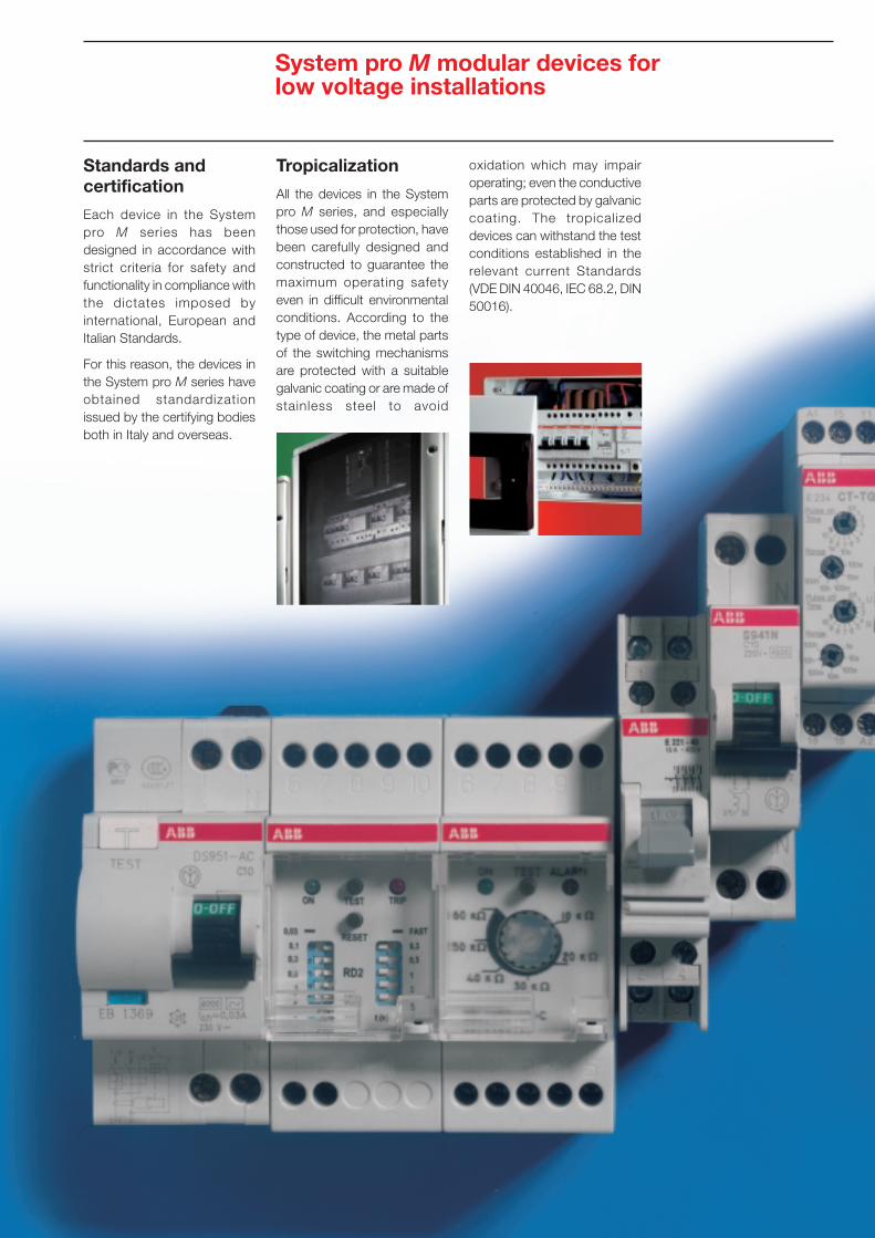
System pro M modular devices forlow voltage installations
Standards andcertification
Each device in the Systempro M series has beendesigned in accordance withstrict criteria for safety andfunctionality in compliance withthe dictates imposed byinternational, European andItalian Standards.
For this reason, the devices inthe System pro M series haveobtained standardizationissued by the certifying bodiesboth in Italy and overseas.
Tropicalization
All the devices in the Systempro M series, and especiallythose used for protection, havebeen carefully designed andconstructed to guarantee themaximum operating safetyeven in difficult environmentalconditions. According to thetype of device, the metal partsof the switching mechanismsare protected with a suitablegalvanic coating or are made ofstainless steel to avoid
oxidation which may impairoperating; even the conductiveparts are protected by galvaniccoating. The tropicalizeddevices can withstand the testconditions established in therelevant current Standards(VDE DIN 40046, IEC 68.2, DIN50016).
0/6 ABB SACE
Unifix cabling system
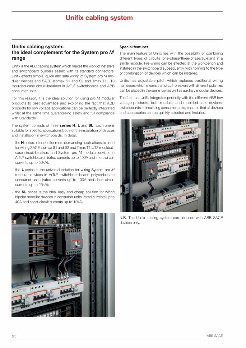
Unifix cabling system:the ideal complement for the System pro Mrange
Unifix is the ABB cabling system which makes the work of installersand switchboard builders easier: with its standard connectors,Unifix effects simple, quick and safe wiring of System pro M mo-dular devices and SACE Isomax S1 and S2 and Tmax T1…T3moulded-case circuit-breakers in ArTu® switchboards and ABBconsumer units.
For this reason, it is the ideal solution for using pro M modularproducts to best advantage and exploiting the fact that ABBproducts for low voltage applications can be perfectly integratedwhilst at the same time guaranteeing safety and full compliancewith Standards.
The system consists of three series H, L and SL. Each one issuitable for specific applications both for the installation of devicesand installation in switchboards. In detail:
- the H series, intended for more demanding applications, is usedfor wiring SACE Isomax S1 and S2 and Tmax T1…T3 moulded-case circuit-breakers and System pro M modular devices inArTu® switchboards (rated currents up to 400A and short-circuitcurrents up to 50kA);
- the L series is the universal solution for wiring System pro Mmodular devices in ArTu® switchboards and polycarbonateconsumer units (rated currents up to 100A and short-circuitcurrents up to 25kA);
- the SL series is the ideal easy and cheap solution for wiringbipolar modular devices in consumer units (rated currents up to40A and short-circuit currents up to 10kA).
Special features
The main feature of Unifix lies with the possibility of combiningdifferent types of circuits (one-phase/three-phase/auxiliary) in asingle module. Pre-wiring can be effected at the workbench andinstalled in the switchboard subsequently, with no limits to the typeor combination of devices which can be installed.
Unifix has adjustable pitch which replaces traditional wiringharnesses which means that circuit-breakers with different polaritiescan be placed in the same row as well as auxiliary modular devices.
The fact that Unifix integrates perfectly with the different ABB lowvoltage products, both modular and moulded-case devices,switchboards or insulating consumer units, ensures that all devicesand accessories can be quickly selected and installed.
N.B. The Unifix cabling system can be used with ABB SACEdevices only.
0/7ABB SACE
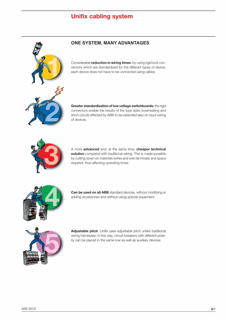
ONE SYSTEM, MANY ADVANTAGES
Considerable reduction in wiring times: by using rigid lock con-nectors which are standardized for the different types of device,each device does not have to be connected using cables
Greater standardization of low voltage switchboards: the rigidconnectors enable the results of the type tests (overheating andshort-circuit) effected by ABB to be extended also on input wiringof devices.
A more advanced and, at the same time, cheaper technicalsolution compared with traditional wiring. This is made possibleby cutting down on materials (wires and wire terminals) and spacerequired, thus affecting operating times
Can be used on all ABB standard devices, without modifying oradding accessories and without using special equipment
Adjustable pitch: Unifix uses adjustable pitch unlike traditionalwiring harnesses; in this way, circuit-breakers with different polar-ity can be placed in the same row as well as auxiliary devices
Unifix cabling system
1
2
3
4
5

1/1
1
Protection, command,load management andmeasurement modular devices
ABB SACE
Contents
General ...................................................................................................................................1/2
Protection devices
RD2 residual current monitors ..................................................................................................1/4
Toroidal transformers ................................................................................................................1/5
E 930 fuse holders ...................................................................................................................1/6
M2160 - M2060 fuse switches .................................................................................................1/8
Command devices
E 259 installation relays ............................................................................................................1/9
E 250 latching relays .............................................................................................................. 1/11
Load management devices
ATS electro-mechanical time switches ...................................................................................1/15
DTS digital time switches .......................................................................................................1/16
TWS twilight switches ............................................................................................................1/17
RAL overload alarms ..............................................................................................................1/18
LSS1/2 load shedding switches .............................................................................................1/19
SQZ3 phase and sequence relays ..........................................................................................1/20
LEE power failure signalling lamp ...........................................................................................1/21
Max./min. current/voltage ammetric and voltmetric relays ......................................................1/22
Measurement devices
Analogue measurement instruments ......................................................................................1/23
Digital measurement instruments ...........................................................................................1/25
MTM multimeters ...................................................................................................................1/26
Accessories for analogue and digital measurement instruments .............................................1/27
HMT electro-mechanical hour meters .....................................................................................1/48
Insulation monitors .................................................................................................................1/49
Other modular functions
TM/TS bell transformers .........................................................................................................1/51
Bells and buzzers ...................................................................................................................1/53
Modular sockets ....................................................................................................................1/54
M9100 modular housing for CBK pushbuttons ......................................................................1/55
1/2
1
ABB SACE
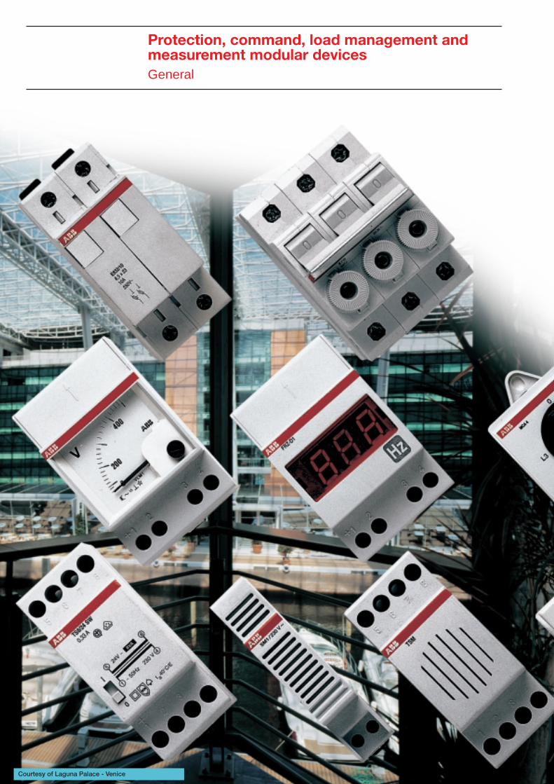
Protection, command, load management andmeasurement modular devicesGeneral
Courtesy of Laguna Palace - Venice
1/3
1
ABB SACE
Protection, command, load management andmeasurement modular devicesGeneral
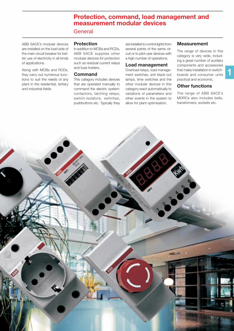
ABB SACE’s modular devicesare installed on the load side ofthe main circuit breaker for bet-ter use of electricity in all kindsof applications.
Along with MCBs and RCDs,they carry out numerous func-tions to suit the needs of anyplant in the residential, tertiaryand industrial fields.
ProtectionIn addition to MCBs and RCDs,ABB SACE supplies othermodular devices for protectionsuch as residual current relaysand fuse holders.
CommandThis category includes devicesthat are operated manually tocommand the electric system:contactors, latching relays,switch-isolators, switches,pushbuttons etc. Typically they
are installed to control lights fromseveral points of the same cir-cuit or to pilot user devices witha high number of operations.
Load managementOverload relays, load manage-ment switches, anti black-outlamps, time switches and theother modular devices in thiscategory react automatically tovariations of parameters andother events in the system toallow for plant optimisation.
MeasurementThe range of devices in thiscategory is very wide, includ-ing a great number of auxiliarycomponents and accessoriesthat make installation in switch-boards and consumer unitspractical and economic.
Other functionsThe range of ABB SACE’sMDRCs also includes bells,transformers, sockets etc.
1
1/4
1
ABB SACE
A selective
Type
Protection devicesRD2 residual current monitors
30 mA … 2 A
I∆n
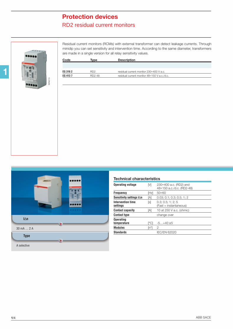
Residual current monitors (RCMs) with external transformer can detect leakage currents. Throughminidip you can set sensitivity and intervention time. According to the same diameter, transformersare made in a single version for all relay sensitivity values.
Code Type Description
EG 316 2 RD2 residual current monitor 230÷400 V a.c.
EG 413 7 RD2-48 residual current monitor 48÷150 V a.c./d.c.
Technical characteristicsOperating voltage [V] 230÷400 a.c. (RD2) and
48÷150 a.c./d.c. (RD2-48)
Frequency [Hz] 50÷60
Sensitivity settings I∆n [A] 0.03; 0.1; 0.3; 0.5; 1; 2
Intervention time [s] 0.3; 0.5; 1; 2; 5settings (Fast = instantaneous)
Contact capacity [A] 10 at 250 V a.c. (ohmic)
Contact type change over
Operatingtemperature [°C] -5…+40 ±5
Modules [n°] 2
Standards IEC/EN 62020
TEP
M01
19
1/5
1
ABB SACE
TEP
M01
20
L1
L2
L3
6 7 8
1 2 3 4 5
9 10
NO NC
N
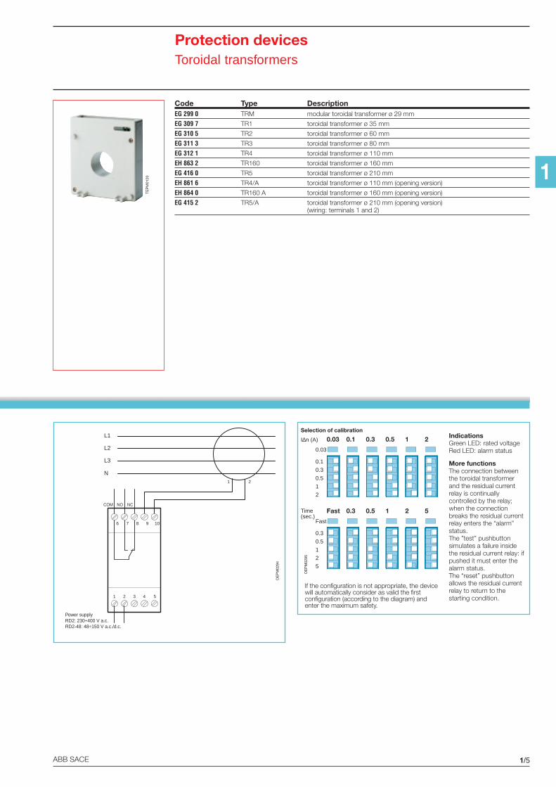
Power supplyRD2: 230÷400 V a.c.RD2-48: 48÷150 V a.c./d.c.
COM
1 2
IndicationsGreen LED: rated voltageRed LED: alarm status
More functionsThe connection betweenthe toroidal transformerand the residual currentrelay is continuallycontrolled by the relay;when the connectionbreaks the residual currentrelay enters the “alarm”status.The ”test” pushbuttonsimulates a failure insidethe residual current relay: ifpushed it must enter thealarm status.The “reset” pushbuttonallows the residual currentrelay to return to thestarting condition.
If the configuration is not appropriate, the devicewill automatically consider as valid the firstconfiguration (according to the diagram) andenter the maximum safety.
OE
PM
0294
OE
PM
0295
Protection devicesToroidal transformers
Code Type DescriptionEG 299 0 TRM modular toroidal transformer ø 29 mm
EG 309 7 TR1 toroidal transformer ø 35 mm
EG 310 5 TR2 toroidal transformer ø 60 mm
EG 311 3 TR3 toroidal transformer ø 80 mm
EG 312 1 TR4 toroidal transformer ø 110 mm
EH 863 2 TR160 toroidal transformer ø 160 mm
EG 416 0 TR5 toroidal transformer ø 210 mm
EH 861 6 TR4/A toroidal transformer ø 110 mm (opening version)
EH 864 0 TR160 A toroidal transformer ø 160 mm (opening version)
EG 415 2 TR5/A toroidal transformer ø 210 mm (opening version)(wiring: terminals 1 and 2)
0.03 0.1 0.3 0.5 1 2
Fast 0.3 0.5 1 2 5
0.03
I∆n (A)
0.1
0.3
0.5
1
2
Fast
Time(sec.)
0.3
0.5
1
2
5
Selection of calibration
1/6
1
ABB SACE
Protection devicesE 930 fuse holders
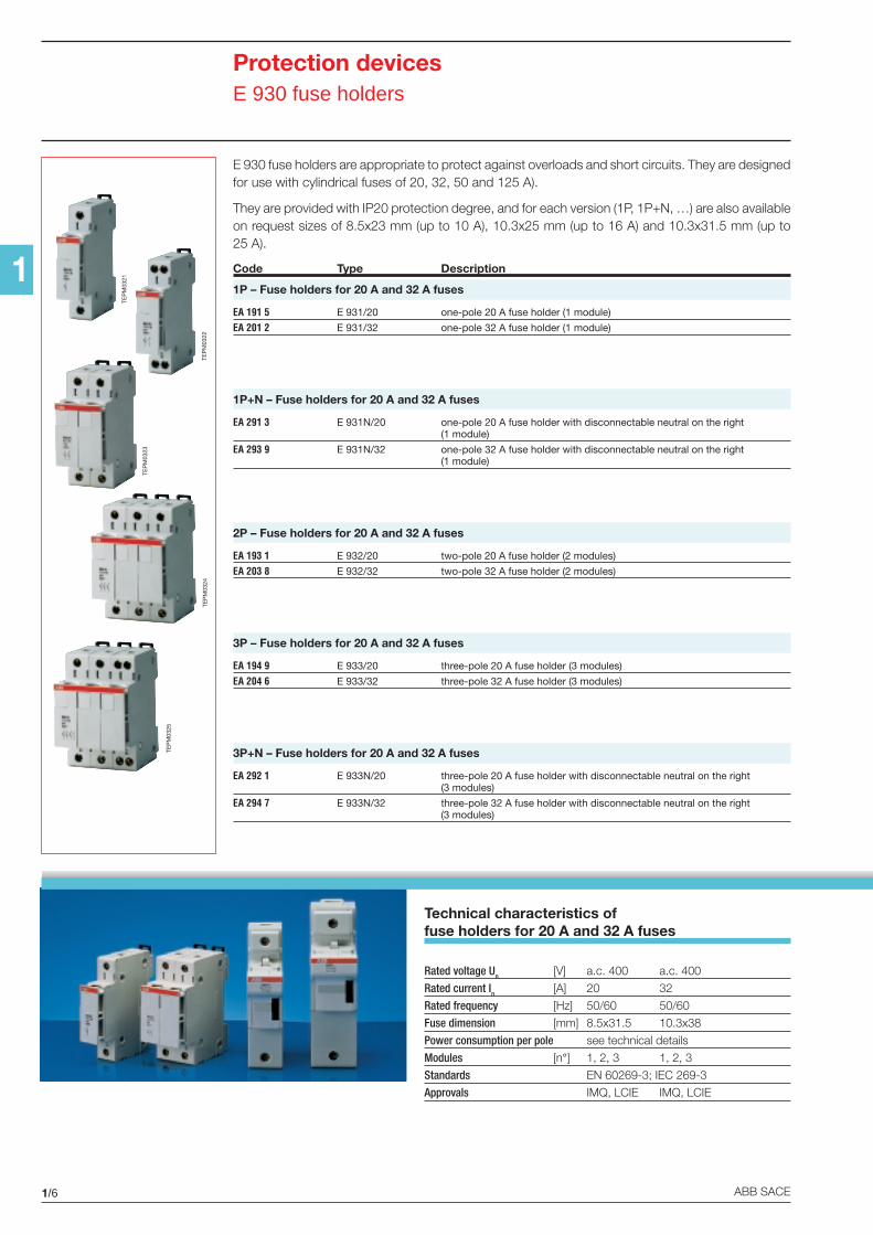
Technical characteristics offuse holders for 20 A and 32 A fuses
Rated voltage Un [V] a.c. 400 a.c. 400
Rated current In [A] 20 32
Rated frequency [Hz] 50/60 50/60
Fuse dimension [mm] 8.5x31.5 10.3x38
Power consumption per pole see technical details
Modules [n°] 1, 2, 3 1, 2, 3
Standards EN 60269-3; IEC 269-3
Approvals IMQ, LCIE IMQ, LCIE
E 930 fuse holders are appropriate to protect against overloads and short circuits. They are designedfor use with cylindrical fuses of 20, 32, 50 and 125 A).
They are provided with IP20 protection degree, and for each version (1P, 1P+N, …) are also availableon request sizes of 8.5x23 mm (up to 10 A), 10.3x25 mm (up to 16 A) and 10.3x31.5 mm (up to25 A).
Code Type Description
1P – Fuse holders for 20 A and 32 A fuses
EA 191 5 E 931/20 one-pole 20 A fuse holder (1 module)
EA 201 2 E 931/32 one-pole 32 A fuse holder (1 module)
1P+N – Fuse holders for 20 A and 32 A fuses
EA 291 3 E 931N/20 one-pole 20 A fuse holder with disconnectable neutral on the right(1 module)
EA 293 9 E 931N/32 one-pole 32 A fuse holder with disconnectable neutral on the right(1 module)
2P – Fuse holders for 20 A and 32 A fuses
EA 193 1 E 932/20 two-pole 20 A fuse holder (2 modules)
EA 203 8 E 932/32 two-pole 32 A fuse holder (2 modules)
3P – Fuse holders for 20 A and 32 A fuses
EA 194 9 E 933/20 three-pole 20 A fuse holder (3 modules)
EA 204 6 E 933/32 three-pole 32 A fuse holder (3 modules)
3P+N – Fuse holders for 20 A and 32 A fuses
EA 292 1 E 933N/20 three-pole 20 A fuse holder with disconnectable neutral on the right(3 modules)
EA 294 7 E 933N/32 three-pole 32 A fuse holder with disconnectable neutral on the right(3 modules)
TEP
M03
21
TEP
M03
22
TEP
M03
23
TEP
M03
24
TEP
M03
25
1/7
1
ABB SACE
Protection devicesE 930 fuse holders
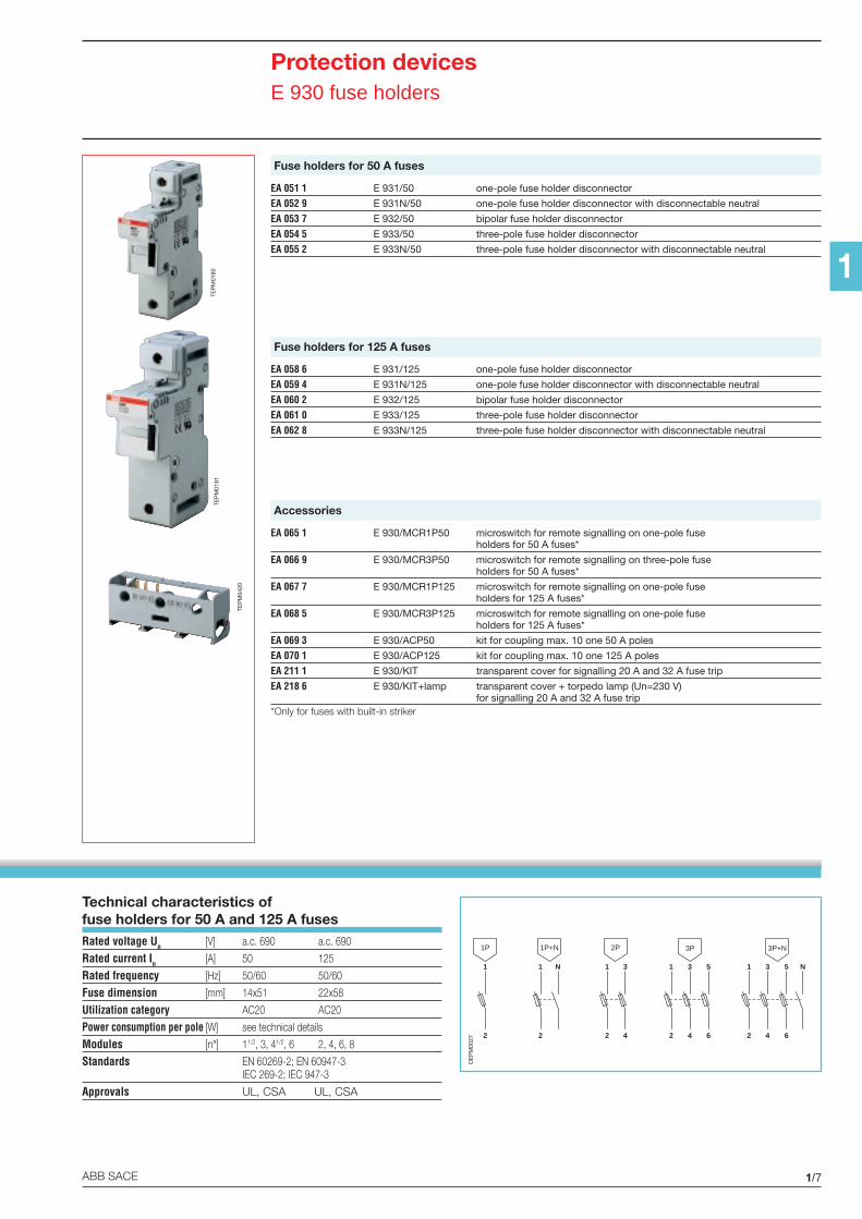
Technical characteristics offuse holders for 50 A and 125 A fusesRated voltage Un [V] a.c. 690 a.c. 690
Rated current In [A] 50 125
Rated frequency [Hz] 50/60 50/60
Fuse dimension [mm] 14x51 22x58
Utilization category AC20 AC20
Power consumption per pole [W] see technical details
Modules [n°] 11/2, 3, 41/2, 6 2, 4, 6, 8
Standards EN 60269-2; EN 60947-3IEC 269-2; IEC 947-3
Approvals UL, CSA UL, CSA
Fuse holders for 50 A fuses
EA 051 1 E 931/50 one-pole fuse holder disconnector
EA 052 9 E 931N/50 one-pole fuse holder disconnector with disconnectable neutral
EA 053 7 E 932/50 bipolar fuse holder disconnector
EA 054 5 E 933/50 three-pole fuse holder disconnector
EA 055 2 E 933N/50 three-pole fuse holder disconnector with disconnectable neutral
Fuse holders for 125 A fuses
EA 058 6 E 931/125 one-pole fuse holder disconnector
EA 059 4 E 931N/125 one-pole fuse holder disconnector with disconnectable neutral
EA 060 2 E 932/125 bipolar fuse holder disconnector
EA 061 0 E 933/125 three-pole fuse holder disconnector
EA 062 8 E 933N/125 three-pole fuse holder disconnector with disconnectable neutral
Accessories
EA 065 1 E 930/MCR1P50 microswitch for remote signalling on one-pole fuseholders for 50 A fuses*
EA 066 9 E 930/MCR3P50 microswitch for remote signalling on three-pole fuseholders for 50 A fuses*
EA 067 7 E 930/MCR1P125 microswitch for remote signalling on one-pole fuseholders for 125 A fuses*
EA 068 5 E 930/MCR3P125 microswitch for remote signalling on one-pole fuseholders for 125 A fuses*
EA 069 3 E 930/ACP50 kit for coupling max. 10 one 50 A poles
EA 070 1 E 930/ACP125 kit for coupling max. 10 one 125 A poles
EA 211 1 E 930/KIT transparent cover for signalling 20 A and 32 A fuse trip
EA 218 6 E 930/KIT+lamp transparent cover + torpedo lamp (Un=230 V)for signalling 20 A and 32 A fuse trip
*Only for fuses with built-in striker
1
2
3
4
2P
1
2
N
1P+N
1
2
1P
1
2
3
4
3P+N
5
6
N1
2
3
4
3P
5
6
OE
PM
0027
TEP
M01
81TE
PM
0180
TEP
M04
20
1/8
1
ABB SACE
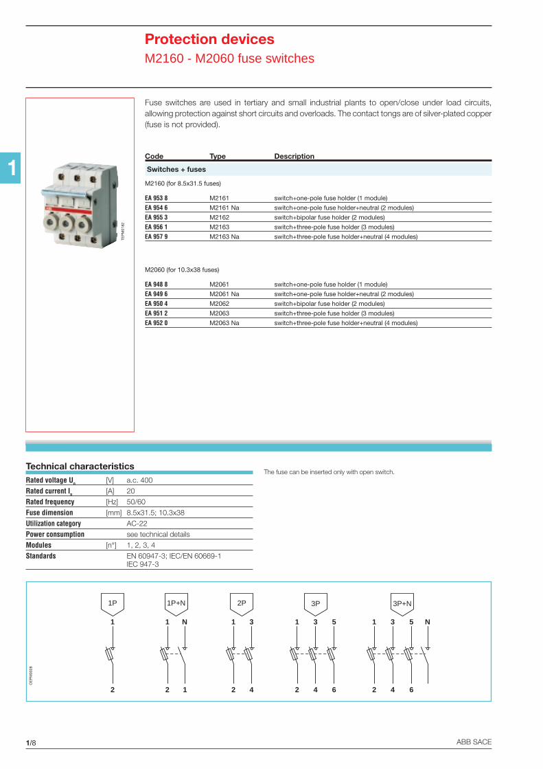
Protection devicesM2160 - M2060 fuse switches
Technical characteristicsRated voltage Un [V] a.c. 400
Rated current In [A] 20
Rated frequency [Hz] 50/60
Fuse dimension [mm] 8.5x31.5; 10.3x38
Utilization category AC-22
Power consumption see technical details
Modules [n°] 1, 2, 3, 4
Standards EN 60947-3; IEC/EN 60669-1IEC 947-3
1
2
3
4
2P
1
2
N
1P+N
1
2
1P
1
2
3
4
3P+N
5
6
N1
2
3
4
3P
5
61
OE
PM
0028
Fuse switches are used in tertiary and small industrial plants to open/close under load circuits,allowing protection against short circuits and overloads. The contact tongs are of silver-plated copper(fuse is not provided).
Code Type Description
Switches + fuses
M2160 (for 8.5x31.5 fuses)
EA 953 8 M2161 switch+one-pole fuse holder (1 module)
EA 954 6 M2161 Na switch+one-pole fuse holder+neutral (2 modules)
EA 955 3 M2162 switch+bipolar fuse holder (2 modules)
EA 956 1 M2163 switch+three-pole fuse holder (3 modules)
EA 957 9 M2163 Na switch+three-pole fuse holder+neutral (4 modules)
M2060 (for 10.3x38 fuses)
EA 948 8 M2061 switch+one-pole fuse holder (1 module)
EA 949 6 M2061 Na switch+one-pole fuse holder+neutral (2 modules)
EA 950 4 M2062 switch+bipolar fuse holder (2 modules)
EA 951 2 M2063 switch+three-pole fuse holder (3 modules)
EA 952 0 M2063 Na switch+three-pole fuse holder+neutral (4 modules)
TEP
M01
82
The fuse can be inserted only with open switch.
1/9ABB SACE
1
Command devicesContactors and installation relays
8 6
7 5
6
5
8
7
42 32
44 34
41 31
42
41
44 32
31
34
8 6
7 5
8
7
6
5
E259 CM20 E259 CM002 E259 CM11
Additinal contact modules
4 2
A1 A2
3 1
4
3
2
1
22 12
24 14
A1 A2
21 11
22
21
24 12
11
14
12 2
14 2
A1 A2
11
12
11
14
4 2
A1 A2
3 1
4
3
2
1
2
A1 A2
1
2
1
E259 R10 E259 R20 E259 R001 E259 R002 E259 R11
Modules with control coil
12
14
11
12
11
14
2
4
3
1
4
3
2
1
2
4
3
1
2
1
4
3
2
4
3
1
2
1
4
3
E250 H02 E250 H20 E250 H11 E250 H001
Auxiliary contacts
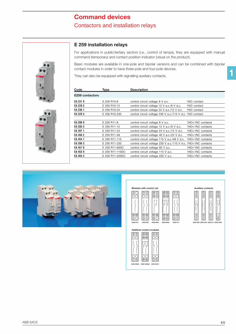
E 259 installation relays
For applications in public/tertiary sectors (i.e., control of lamps), they are equipped with manualcommand (temporary) and contact position indicator (visual on the product).
Basic modules are available in one-pole and bipolar versions and can be combined with bipolarcontact modules in order to have three-pole and four-pole devices.
They can also be equipped with signalling auxiliary contacts.
Code Type Description
E259 contactors
EA 231 9 E 259 R10-8 control circuit voltage 8 V a.c. 1NO contact
EA 228 5 E 259 R10-12 control circuit voltage 12 V a.c./6 V d.c. 1NO contact
EA 230 1 E 259 R10-24 control circuit voltage 24 V a.c./12 V d.c. 1NO contact
EA 229 3 E 259 R10-230 control circuit voltage 230 V a.c./115 V d.c. 1NO contact
EA 288 9 E 259 R11-8 control circuit voltage 8 V a.c. 1NO+1NC contacts
EA 285 5 E 259 R11-12 control circuit voltage 12 V a.c./6 V d.c. 1NO+1NC contacts
EA 287 1 E 259 R11-24 control circuit voltage 24 V a.c./12 V d.c. 1NO+1NC contacts
EA 456 2 E 259 R11-48 control circuit voltage 48 V a.c./24 V d.c. 1NO+1NC contacts
EA 454 7 E 259 R11-115 control circuit voltage 115 V a.c./48 V d.c. 1NO+1NC contacts
EA 286 3 E 259 R11-230 control circuit voltage 230 V a.c./115 V d.c. 1NO+1NC contacts
EA 457 0 E 259 R11-60DC control circuit voltage 60 V a.c. 1NO+1NC contacts
EA 453 9 E 259 R11-110DC control circuit voltage 115 V a.c. 1NO+1NC contacts
EA 455 4 E 259 R11-220DC control circuit voltage 220 V a.c. 1NO+1NC contacts
1/10 ABB SACE
1
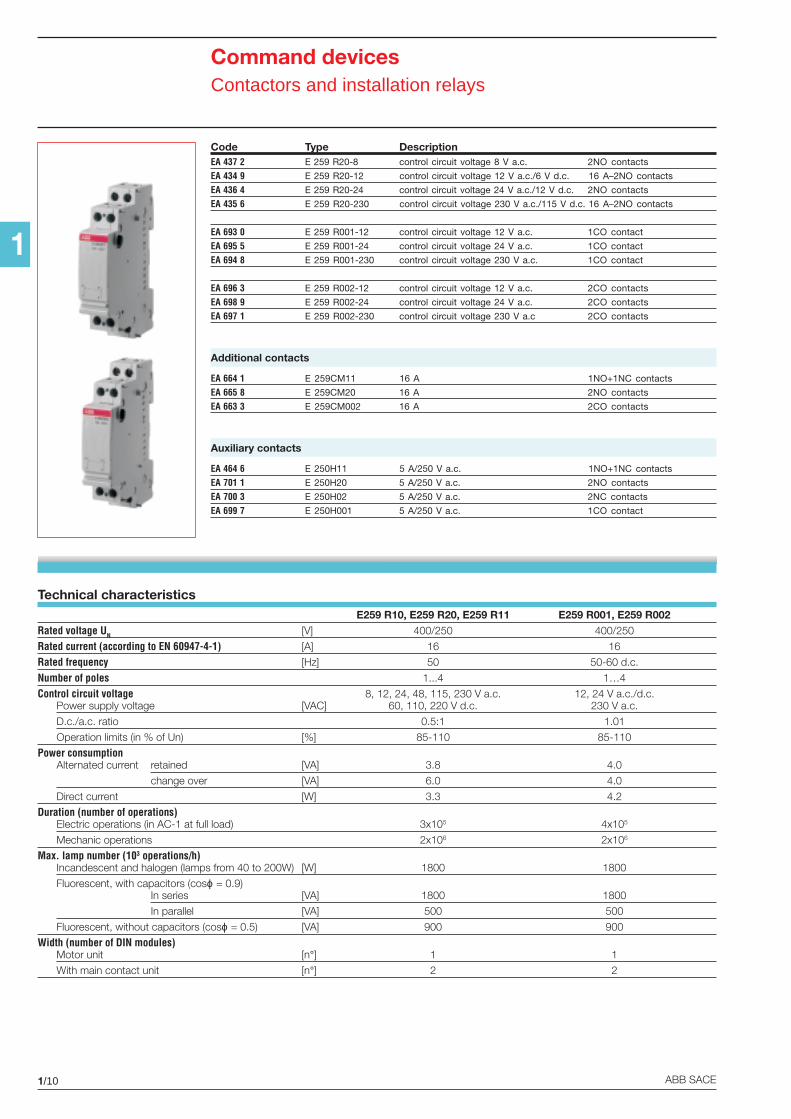
Technical characteristicsE259 R10, E259 R20, E259 R11 E259 R001, E259 R002
Rated voltage UN [V] 400/250 400/250
Rated current (according to EN 60947-4-1) [A] 16 16
Rated frequency [Hz] 50 50-60 d.c.
Number of poles 1...4 1…4
Control circuit voltage 8, 12, 24, 48, 115, 230 V a.c. 12, 24 V a.c./d.c.Power supply voltage [VAC] 60, 110, 220 V d.c. 230 V a.c.
D.c./a.c. ratio 0.5:1 1.01
Operation limits (in % of Un) [%] 85-110 85-110
Power consumptionAlternated current retained [VA] 3.8 4.0
change over [VA] 6.0 4.0
Direct current [W] 3.3 4.2
Duration (number of operations)Electric operations (in AC-1 at full load) 3x10⁵ 4x10⁵
Mechanic operations 2x10⁶ 2x10⁶
Max. lamp number (103 operations/h)Incandescent and halogen (lamps from 40 to 200W) [W] 1800 1800
Fluorescent, with capacitors (cosϕ = 0.9)In series [VA] 1800 1800
In parallel [VA] 500 500
Fluorescent, without capacitors (cosϕ = 0.5) [VA] 900 900
Width (number of DIN modules)Motor unit [n°] 1 1
With main contact unit [n°] 2 2
Code Type DescriptionEA 437 2 E 259 R20-8 control circuit voltage 8 V a.c. 2NO contacts
EA 434 9 E 259 R20-12 control circuit voltage 12 V a.c./6 V d.c. 16 A–2NO contacts
EA 436 4 E 259 R20-24 control circuit voltage 24 V a.c./12 V d.c. 2NO contacts
EA 435 6 E 259 R20-230 control circuit voltage 230 V a.c./115 V d.c. 16 A–2NO contacts
EA 693 0 E 259 R001-12 control circuit voltage 12 V a.c. 1CO contact
EA 695 5 E 259 R001-24 control circuit voltage 24 V a.c. 1CO contact
EA 694 8 E 259 R001-230 control circuit voltage 230 V a.c. 1CO contact
EA 696 3 E 259 R002-12 control circuit voltage 12 V a.c. 2CO contacts
EA 698 9 E 259 R002-24 control circuit voltage 24 V a.c. 2CO contacts
EA 697 1 E 259 R002-230 control circuit voltage 230 V a.c 2CO contacts
Additional contacts
EA 664 1 E 259CM11 16 A 1NO+1NC contacts
EA 665 8 E 259CM20 16 A 2NO contacts
EA 663 3 E 259CM002 16 A 2CO contacts
Auxiliary contacts
EA 464 6 E 250H11 5 A/250 V a.c. 1NO+1NC contacts
EA 701 1 E 250H20 5 A/250 V a.c. 2NO contacts
EA 700 3 E 250H02 5 A/250 V a.c. 2NC contacts
EA 699 7 E 250H001 5 A/250 V a.c. 1CO contact
Command devicesContactors and installation relays
1/11ABB SACE
1
Command devicesLatching relays
E 251-
10
A
0A2
CONTACTSWITCHING
AE 252-
1
2
3
4
0A+B
0A+B
A BA BCONTACT
SWITCHING
E 256-
3 1
4 2
BA
BA
A BCONTACT
SWITCHINGE 255-
1 30
B
A+BA2 4
A BSEQUENCE OF
CONTACTSWITCHING
E 256-2E 256-1
E257 C002 – local and/or centralizedpushbutton
E 257 C002
OFF ON
OFFON
L
N
Local
Local and centralized pushbutton: same lineVAC: L or N - VDC: +
OFF ON
OFFON
L
N
Centrale
Locale
Group centralized control: wiring diagram for E250 GM
E25X
OFF ON
Generalmainpushbutton
OFF ON
Mainpushbuttongroup 1
OFF ON
Mainpushbuttongroup 1
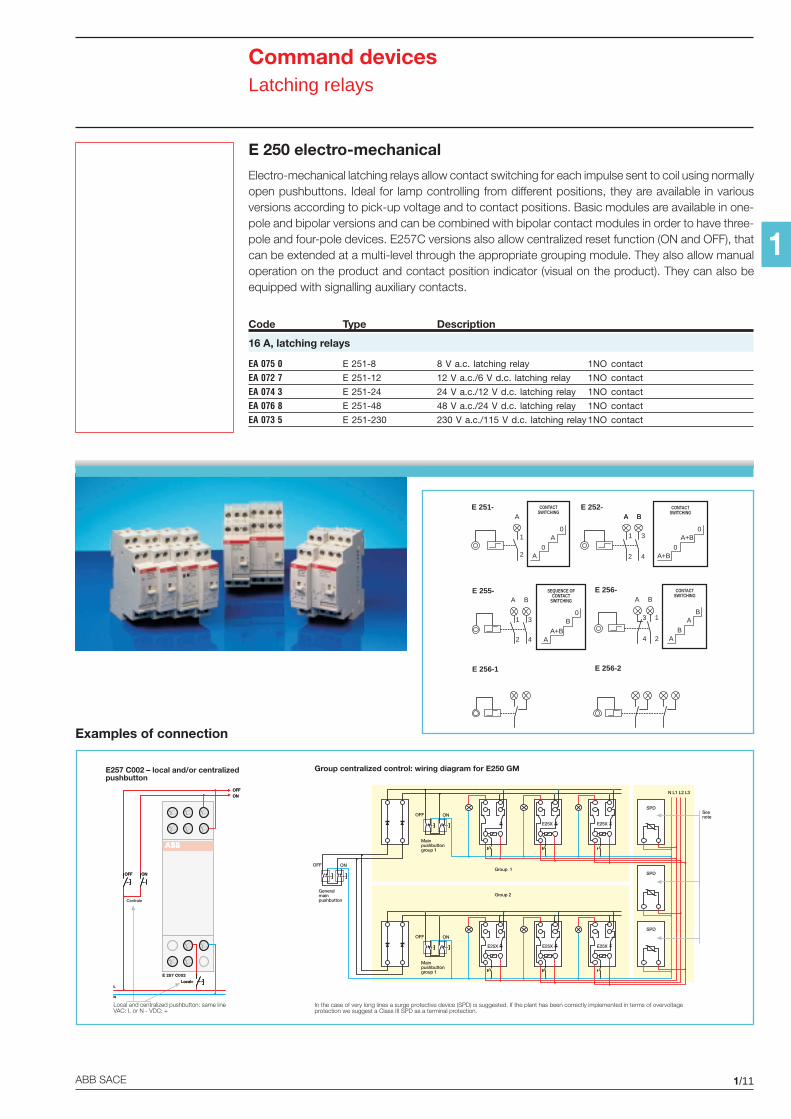
In the case of very long lines a surge protective device (SPD) is suggested. If the plant has been correctly implemented in terms of overvoltageprotection we suggest a Class III SPD as a terminal protection.
Group 1
Group 2
E25X E25X
E25X E25X E25X
SPD
SPD
SPD
N L1 L2 L3
Seenote
E 250 electro-mechanical
Electro-mechanical latching relays allow contact switching for each impulse sent to coil using normallyopen pushbuttons. Ideal for lamp controlling from different positions, they are available in variousversions according to pick-up voltage and to contact positions. Basic modules are available in one-pole and bipolar versions and can be combined with bipolar contact modules in order to have three-pole and four-pole devices. E257C versions also allow centralized reset function (ON and OFF), thatcan be extended at a multi-level through the appropriate grouping module. They also allow manualoperation on the product and contact position indicator (visual on the product). They can also beequipped with signalling auxiliary contacts.
Code Type Description
16 A, latching relays
EA 075 0 E 251-8 8 V a.c. latching relay 1NO contact
EA 072 7 E 251-12 12 V a.c./6 V d.c. latching relay 1NO contact
EA 074 3 E 251-24 24 V a.c./12 V d.c. latching relay 1NO contact
EA 076 8 E 251-48 48 V a.c./24 V d.c. latching relay 1NO contact
EA 073 5 E 251-230 230 V a.c./115 V d.c. latching relay 1NO contact
Examples of connection
1/12 ABB SACE
1
Command devicesLatching relays
8 6
7 5
8
7
6
5
42 32
44 34
41 31
42
41
44 32
31
34
8 6
7 5
8
7
6
5
E 250 CM20 E 250 CM11 E 250 CM002
2
4
3
1
4
3
2
1
2
4
3
1
2
1
4
3
2
4
3
1
2
1
4
3
E 257 H02 E 250 H20 E 250 H11
ON
OFF
3
1
E 257 CM
E 257 C30 E 257 C003
32 22
31 21
ON
34 24 OFF
A2
32
31
34 22
21
24
12
11
14
A1
12
11
14
6 4
5 3
ON
OFF
A2
6
5
4
3
1
1
A1
2
1
E 257 C20 E 257 C002
4 2
3 1
4
3
2
1
ON
OFF
A1 A2
22 12
21 11
ON
24 14 OFF
A1 A2
22
21
24 12
11
14
4 2
A1 A2
3 1
4
3
2
1
22 12
24 14
A1 A2
21 11
22
21
24 12
11
14
12 2
14 2
A1 A2
11
12
11
14
4 2
A1 A2
3 1
4
3
2
1
2
A1 A2
1
2
1
E 251 E 252 E 255 E256 E 256.2
4 2
A1 A2
3 1
4
3
2
1
B A
12 ON
14 OFF
A1 A2
11
12
11
14
2
A1 A2
1
2
1
ON
OFF
E 256.1 E 257 C10 E 257 C001
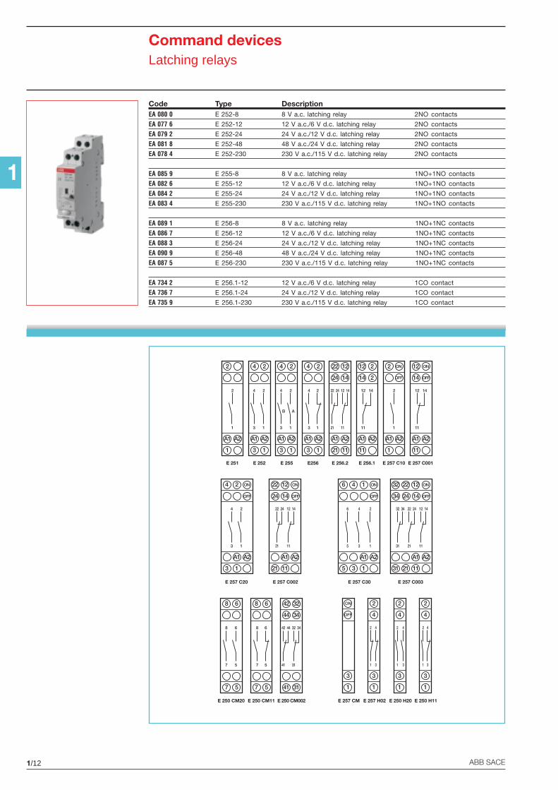
Code Type DescriptionEA 080 0 E 252-8 8 V a.c. latching relay 2NO contacts
EA 077 6 E 252-12 12 V a.c./6 V d.c. latching relay 2NO contacts
EA 079 2 E 252-24 24 V a.c./12 V d.c. latching relay 2NO contacts
EA 081 8 E 252-48 48 V a.c./24 V d.c. latching relay 2NO contacts
EA 078 4 E 252-230 230 V a.c./115 V d.c. latching relay 2NO contacts
EA 085 9 E 255-8 8 V a.c. latching relay 1NO+1NO contacts
EA 082 6 E 255-12 12 V a.c./6 V d.c. latching relay 1NO+1NO contacts
EA 084 2 E 255-24 24 V a.c./12 V d.c. latching relay 1NO+1NO contacts
EA 083 4 E 255-230 230 V a.c./115 V d.c. latching relay 1NO+1NO contacts
EA 089 1 E 256-8 8 V a.c. latching relay 1NO+1NC contacts
EA 086 7 E 256-12 12 V a.c./6 V d.c. latching relay 1NO+1NC contacts
EA 088 3 E 256-24 24 V a.c./12 V d.c. latching relay 1NO+1NC contacts
EA 090 9 E 256-48 48 V a.c./24 V d.c. latching relay 1NO+1NC contacts
EA 087 5 E 256-230 230 V a.c./115 V d.c. latching relay 1NO+1NC contacts
EA 734 2 E 256.1-12 12 V a.c./6 V d.c. latching relay 1CO contact
EA 736 7 E 256.1-24 24 V a.c./12 V d.c. latching relay 1CO contact
EA 735 9 E 256.1-230 230 V a.c./115 V d.c. latching relay 1CO contact
1/13ABB SACE
1
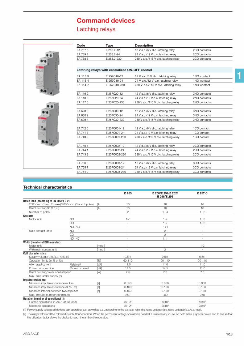
Technical characteristicsE 255 E 250/E 251/E 252/ E 257 C
E 256/E 256
Rated load (according to EN 60669-2-2)250 V a.c. (1 and 2 poles)/400 V a.c. (3 and 4 poles) [A] 16 16 16Direct current (30 V d.c.) [A] 16 16 16Number of poles 2 1...4 1...3
ContactsMotor unit NO 1+1 1-2 1...3
CO - 1-2 1...3NO+NC - 1+1 -
Main contact units NO - 2 -CO - 2 -NO+NC - 1+1 -
Width (number of DIN modules)Motor unit [mod.] 1 1 1-2With main contact unit [mod.] - 2 -
Coil characteristicsSupply voltage: d.c./a.c. ratio (1) 0.5:1 0.5:1 0.5:1Operation limits (in % of Un) [%] 90-110 90-110 90-110Alternated current Retained [VA] 11.0 11.0 11.0Power consumption Pick-up current [VA] 14.5 14.5 11.0Direct current power consumption [W] 7.5 7.5 7.5Max. time under supply (2)
Impulse enduranceMinimum impulse endurance (at Un) [s] 0.050 0.050 0.050Minimum impulse endurance (90% Un) [s] 0.100 0.100 0.100Minimum interval between two impulses [s] 0.150 0.150 0.150Max. impulse number per minute 250 250 250
Duration (number of operations) (3)Electric operations (in AC-1 at full load) 3x10⁵ 4x10⁵ 4x10⁵
Mechanic operations 2x10⁶ 2x10⁶ 2x10⁶
(1) Power supply voltage: all devices can operate at a.c. as well as d.c., according to the d.c./a.c. ratio: d.c. rated voltage=(a.c. rated voltage)x(d.c./a.c. ratio).
(2) The relays withstand the “blocked pushbutton” condition. When the permanent voltage operation is needed, it is necessary to use, on both sides, a spacer device and to ensure thatthe utilization factor allows the device to reach the ambient temperature.
Command devicesLatching relays
Code Type DescriptionEA 737 5 E 256.2-12 12 V a.c./6 V d.c. latching relay 2CO contacts
EA 739 1 E 256.2-24 24 V a.c./12 V d.c. latching relay 2CO contacts
EA 738 3 E 256.2-230 230 V a.c./115 V d.c. latching relay 2CO contacts
Latching relays with centralized ON-OFF control
EA 113 9 E 257C10-12 12 V a.c./6 V d.c. latching relay 1NO contact
EA 115 4 E 257C10-24 24 V a.c./12 V d.c. latching relay 1NO contact
EA 114 7 E 257C10-230 230 V a.c./115 V d.c. latching relay 1NO contact
EA 116 2 E 257C20-12 12 V a.c./6 V d.c. latching relay 2NO contacts
EA 118 8 E 257C20-24 24 V a.c./12 V d.c. latching relay 2NO contacts
EA 117 0 E 257C20-230 230 V a.c./115 V d.c. latching relay 2NO contacts
EA 628 6 E 257C30-12 12 V a.c./6 V d.c. latching relay 3NO contacts
EA 630 2 E 257C30-24 24 V a.c./12 V d.c. latching relay 3NO contacts
EA 629 4 E 257C30-230 230 V a.c./115 V d.c. latching relay 3NO contacts
EA 742 5 E 257C001-12 12 V a.c./6 V d.c. latching relay 1CO contact
EA 741 7 E 257C001-24 24 V a.c./12 V d.c. latching relay 1CO contact
EA 740 9 E 257C001-230 230 V a.c./115 V d.c. latching relay 1CO contact
EA 745 8 E 257C002-12 12 V a.c./6 V d.c. latching relay 2CO contacts
EA 744 1 E 257C002-24 24 V a.c./12 V d.c. latching relay 2CO contacts
EA 743 3 E 257C002-230 230 V a.c./115 V d.c. latching relay 2CO contacts
EA 756 5 E 257C003-12 12 V a.c./6 V d.c. latching relay 3CO contacts
EA 755 7 E 257C003-24 24 V a.c./12 V d.c. latching relay 3CO contacts
EA 754 0 E 257C003-230 230 V a.c./115 V d.c. latching relay 3CO contacts
1/14 ABB SACE
1
Command devicesLatching relays
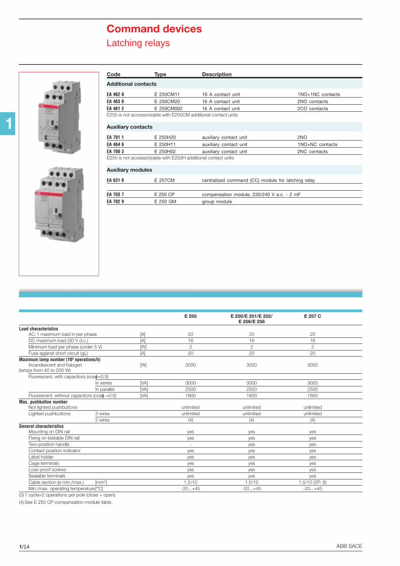
E 255 E 250/E 251/E 252/ E 257 CE 256/E 256
Load characteristicsAC-1 maximum load in per phase [A] 20 20 20DC maximum load (30 V d.c.) [A] 16 16 16Minimum load per phase (under 5 V) [W] 2 2 2Fuse against short circuit (gL) [A] 20 20 20
Maximum lamp number (103 operations/h)Incandescent and halogen [W] 3000 3000 3000
(lamps from 40 to 200 W)Fluorescent, with capacitors (cosϕ=0.9)
In series [VA] 3000 3000 3000In parallel [VA] 2500 2500 2500
Fluorescent, without capacitors (cosϕ =0.5) [VA] 1800 1800 1800Max. pushbutton number
Not lighted pushbuttons unlimited unlimited unlimitedLighted pushbuttons 3 wires unlimited unlimited unlimited
2 wires (4) (4) (4)General characteristics
Mounting on DIN rail yes yes yesFixing on bistable DIN rail yes yes yesTwo-position handle - yes yesContact position indicator yes yes yesLabel holder yes yes yesCage terminals yes yes yesLoss-proof screws yes yes yesSealable terminals yes yes yesCable section (ø min./max.) [mm2] 1.5/10 1.5/10 1.5/10 (2P: 6)Min./max. operating temperature[°C] -20...+45 -20...+45 -20...+45
(3) 1 cycle=2 operations per pole (close + open).
(4) See E 250 CP compensation module table.
Code Type Description
Additional contacts
EA 462 0 E 250CM11 16 A contact unit 1NO+1NC contacts
EA 463 8 E 250CM20 16 A contact unit 2NO contacts
EA 461 2 E 250CM002 16 A contact unit 2CO contactsE255 is not accessorizable with E250CM additional contact units
Auxiliary contacts
EA 701 1 E 250H20 auxiliary contact unit 2NO
EA 464 6 E 250H11 auxiliary contact unit 1NO+NC contacts
EA 700 3 E 250H02 auxiliary contact unit 2NC contactsE255 is not accessorizable with E250H additional contact units
Auxiliary modules
EA 631 0 E 257CM centralized command (CC) module for latching relay
EA 703 7 E 250 CP compensation module, 230/240 V a.c. - 2 mF
EA 702 9 E 250 GM group module
1/15ABB SACE
1
Load management devicesTime switches
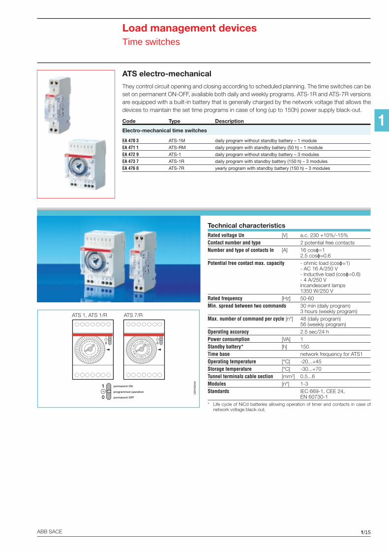
ATS electro-mechanical
They control circuit opening and closing according to scheduled planning. The time switches can beset on permanent ON-OFF, available both daily and weekly programs. ATS-1R and ATS-7R versionsare equipped with a built-in battery that is generally charged by the network voltage that allows thedevices to maintain the set time programs in case of long (up to 150h) power supply black-out.
Code Type Description
Electro-mechanical time switches
EA 470 3 ATS-1M daily program without standby battery – 1 module
EA 471 1 ATS-RM daily program with standby battery (50 h) – 1 module
EA 472 9 ATS-1 daily program without standby battery – 3 modules
EA 473 7 ATS-1R daily program with standby battery (150 h) – 3 modules
EA 476 0 ATS-7R yearly program with standby battery (150 h) – 3 modules
Technical characteristicsRated voltage Un [V] a.c. 230 +10%/-15%Contact number and type 2 potential free contactsNumber and type of contacts In [A] 16 cosϕ=1
2.5 cosϕ=0.6Potential free contact max. capacity - ohmic load (cosϕ=1)
- AC 16 A/250 V- inductive load (cosϕ=0.6)- 4 A/250 Vincandescent lamps1350 W/250 V
Rated frequency [Hz] 50-60Min. spread between two commands 30 min (daily program)
3 hours (weekly program)Max. number of command per cycle [n°] 48 (daily program)
56 (weekly program)Operating accuracy 2.5 sec/24 hPower consumption [VA] 1Standby battery* [h] 150Time base network frequency for ATS1Operating temperature [°C] -20...+45Storage temperature [°C] -30...+70Tunnel terminals cable section [mm2] 0.5...6Modules [n°] 1-3Standards IEC 669-1, CEE 24,
EN 60730-1* Life cycle of NiCd batteries allowing operation of timer and contacts in case of
network voltage black-out.
OE
PM
0046
ATS 1, ATS 1/R ATS 7/R
123456
78
910
11
12 13 14 15 16 1718
1920
21222324
1
0
612
186
1218
6
12 18 6 12
186
1218
6
1218
1
0
1
0
permanent ON
programmed operation
permanent OFF
1/16 ABB SACE
1
Load management devicesTime switches
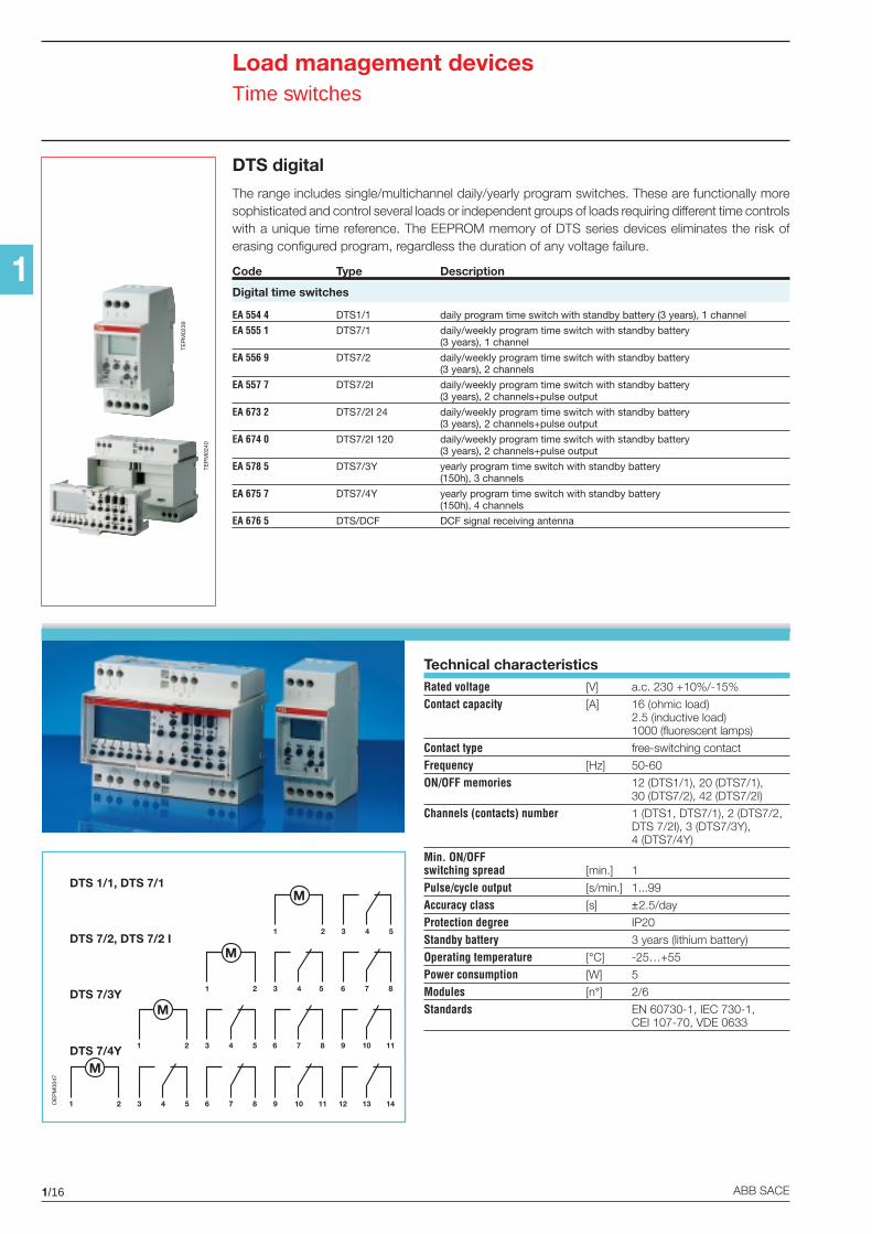
DTS digital
The range includes single/multichannel daily/yearly program switches. These are functionally moresophisticated and control several loads or independent groups of loads requiring different time controlswith a unique time reference. The EEPROM memory of DTS series devices eliminates the risk oferasing configured program, regardless the duration of any voltage failure.
Code Type Description
Digital time switches
EA 554 4 DTS1/1 daily program time switch with standby battery (3 years), 1 channel
EA 555 1 DTS7/1 daily/weekly program time switch with standby battery(3 years), 1 channel
EA 556 9 DTS7/2 daily/weekly program time switch with standby battery(3 years), 2 channels
EA 557 7 DTS7/2I daily/weekly program time switch with standby battery(3 years), 2 channels+pulse output
EA 673 2 DTS7/2I 24 daily/weekly program time switch with standby battery(3 years), 2 channels+pulse output
EA 674 0 DTS7/2I 120 daily/weekly program time switch with standby battery(3 years), 2 channels+pulse output
EA 578 5 DTS7/3Y yearly program time switch with standby battery(150h), 3 channels
EA 675 7 DTS7/4Y yearly program time switch with standby battery(150h), 4 channels
EA 676 5 DTS/DCF DCF signal receiving antenna
1 2 3 54 6 87 9 1110
1 2 3 54 6 87
1 2 3 54
1 2 3 54 6 87 9 1110 12 1413OE
PM
0047
DTS 1/1, DTS 7/1
DTS 7/2, DTS 7/2 I
DTS 7/3Y
Technical characteristicsRated voltage [V] a.c. 230 +10%/-15%
Contact capacity [A] 16 (ohmic load)2.5 (inductive load)1000 (fluorescent lamps)
Contact type free-switching contact
Frequency [Hz] 50-60
ON/OFF memories 12 (DTS1/1), 20 (DTS7/1),30 (DTS7/2), 42 (DTS7/2I)
Channels (contacts) number 1 (DTS1, DTS7/1), 2 (DTS7/2,DTS 7/2I), 3 (DTS7/3Y),4 (DTS7/4Y)
Min. ON/OFFswitching spread [min.] 1
Pulse/cycle output [s/min.] 1...99
Accuracy class [s] ±2.5/day
Protection degree IP20
Standby battery 3 years (lithium battery)
Operating temperature [°C] -25…+55
Power consumption [W] 5
Modules [n°] 2/6
Standards EN 60730-1, IEC 730-1,CEI 107-70, VDE 0633
TEP
M02
39
TEP
M02
40
DTS 7/4Y
1/17ABB SACE
1
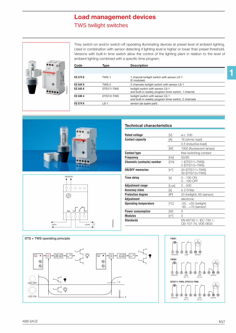
Load management devicesTWS twilight switches
They switch-on and/or switch-off operating illuminating devices at preset level of ambient lighting.Used in combination with sensor detecting if lighting level is higher or lower than preset threshold.Versions with built-in time switch allow the control of the lighting plant in relation to the level ofambient lighting combined with a specific time program.
Code Type Description
EG 573 8 TWS-1 1 channel twilight switch with sensor LS-1(2 modules)
EG 544 9 TWS-2 2 channels twilight switch with sensor LS-1
EG 545 6 DTS7/1-TWS twilight switch with sensor LS-1and built-in weekly program timer switch, 1 channel
EG 546 4 DTS7/2-TWS twilight switch with sensor LS-1and built-in weekly program timer switch, 2 channels
EG 574 6 LS-1 sensor (as spare part)
TEP
M02
44
Technical characteristics
Rated voltage [V] a.c. 230Contact capacity [A] 16 (ohmic load)
2.5 (inductive load)[W] 1000 (fluorescent lamps)
Contact type free-switching contactFrequency [Hz] 50/60Channels (contacts) number [Ch] 1 (DTS7/1+TWS)
2 (DTS7/2+TWS)ON/OFF memories [n°] 20 (DTS7/1+TWS)
30 (DTS7/2+TWS)Time delay [s] 0…100 ON
0…100 OFFAdjustment range [Lux] 2…500Accuracy class [s] ± 2.5/dayProtection degree [IP] 20 (twilight), 65 (sensor)Adjustment electronicOperating temperature [°C] -25…+55 (twilight)
-30…+70 (sensor)Power consumption [W] 5Modules [n°] 3Standards EN 60730-1, IEC 730-1,
CEI 107-70, VDE 0633
OE
PM
0050
1 2 3 5
230V~ LOAD
4
6 7
NA NCC
SENSOR
OE
PM
0050
DTS + TWS operating principle
DTS +TWS
LEDON
0...100sec.
DTS +TWS
LEDOFF
76
8
43
5
43
5
43
5
76
8
43
50...100sec.
˜ 1,3
t
LED OFF
LED ON
1 2 3 4 5 10 11
M~
network user sensor
1 2 3 4 5 6 7 8 9 10 11
M~
network user(ch 1)
user(ch 2)
sensor
1 2 3 4 5 6 7 8 9 10 11
M~
network user(ch 1)
user(ch 2)
sensor
TWS1
TWS2
DTS7/1-TWS, DTS7/2-TWS
1/18 ABB SACE
1
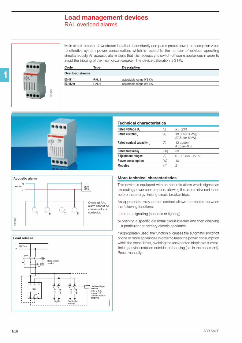
Load management devicesRAL overload alarms
Technical characteristicsRated voltage Un [V] a.c. 230
Rated current In [A] 18.3 (for 3 kW);27.5 (for 6 kW)
Rated contact capacity In [A] 12 cosϕ=14 cosϕ=0.8
Rated frequency [Hz] 50
Adjustment ranges [A] 0 ...18.3/0…27.5
Power consumption [W] 10
Modules [n°] 2
Main circuit-breaker downstream installed, it constantly compares preset power consumption valueto effective system power consumption, which is related to the number of devices operatingsimultaneously. An acoustic alarm alerts that it is necessary to switch-off some appliances in order toavoid the tripping of the main circuit-breaker. The device calibration is 3 kW.
Code Type Description
Overload alarms
EG 411 1 RAL 3 adjustable range 0/3 kW
EG 412 9 RAL 6 adjustable range 0/6 kW
TEP
M02
45
More technical characteristics
This device is equipped with an acoustic alarm which signals anexceeding power consumption, allowing the user to disinsert loadsbefore the energy-limiting circuit-breaker trips.
An appropriate relay output contact allows the choice betweenthe following functions:
a) remote signalling (acoustic or lighting)
b) opening a specific divisional circuit-breaker and then disablinga particular not primary electric appliance.
If appropriately used, the function b) causes the automatic switchoffof one or more appliances in order to keep the power consumptionwithin the preset limits, avoiding the unexpected tripping of current-limiting device installed outside the housing (i.e. in the basement).Reset manually.
5 6 7 8
N U3kWMAXL
230 V~
Overload RALalarm cannot beconnected to acontactor.
Main circuitbreaker
Undervoltagerelease(230 V a.c.)in case ofcircuit-breakertripping
Dedicatedsocket
Lights
RAL
5 8
1 3
L
N230 V a.c.
6
2
OE
PM
0052
OE
PM
0051
Acoustic alarm
Load release
1/19ABB SACE
1
Load management devicesLSS1/2 load shedding switches
Technical characteristicsRated voltage Un [V] a.c. 230
Rated capacity In [A] 90
Rated contact capacity In [A] 16 eachNPL1 and NPL2 (terminals 12 and 14)
Rated frequency [Hz] 50/60
Regulating thresholds [A] 5...3010...6015...90
Load reinsertion delay 5-7 min. (NPL1)4-5, 50 min. (NPL2)
Load disinsertion delay about 2 sec.
Indicators 1 green LED=supply voltage available
2 red LED=switched off loads
Load OFFremote signalling [A] 1 (terminals 11 and 13)
Terminals Primary load 35 mm2
Not primary loads 10 mm2
Power consumption [W] 5
Modules [n°] 5
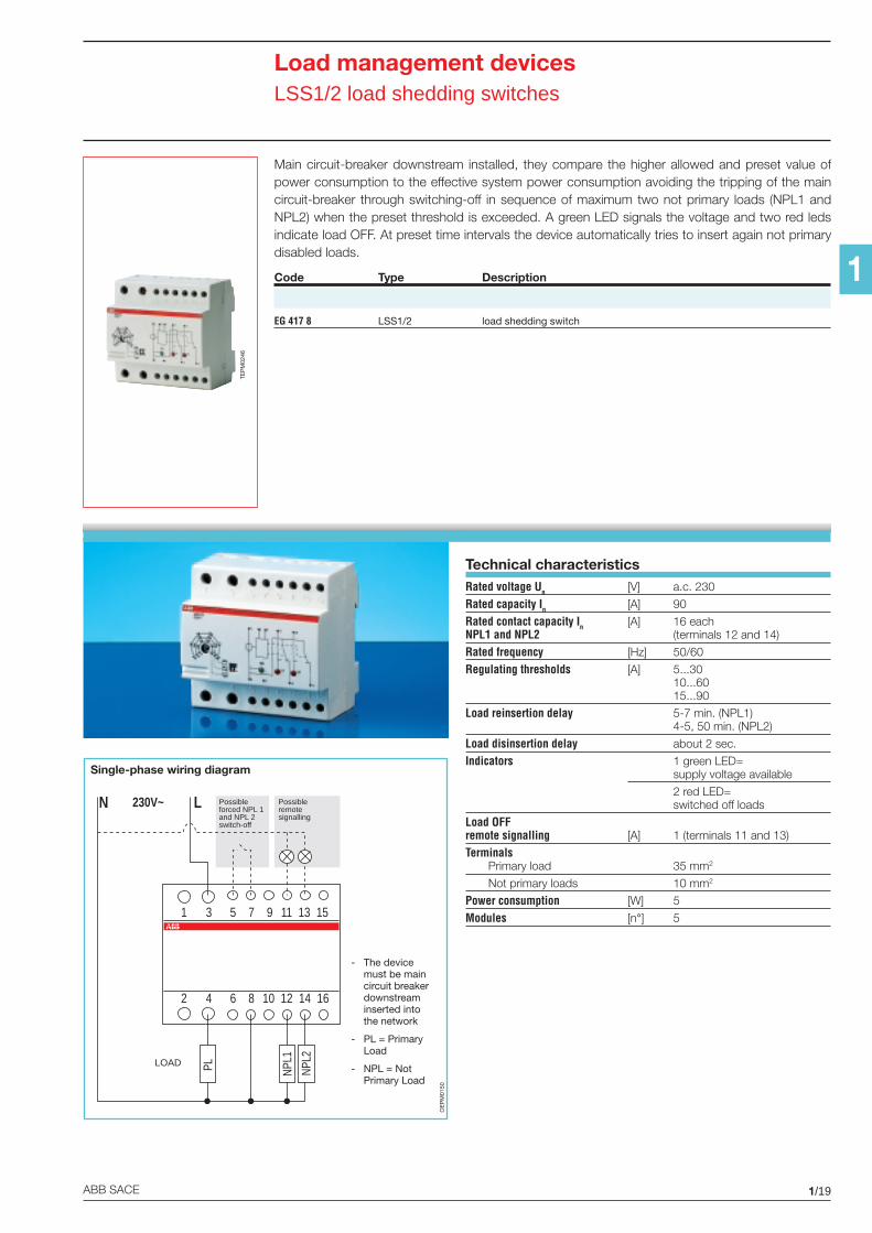
Main circuit-breaker downstream installed, they compare the higher allowed and preset value ofpower consumption to the effective system power consumption avoiding the tripping of the maincircuit-breaker through switching-off in sequence of maximum two not primary loads (NPL1 andNPL2) when the preset threshold is exceeded. A green LED signals the voltage and two red ledsindicate load OFF. At preset time intervals the device automatically tries to insert again not primarydisabled loads.
Code Type Description
EG 417 8 LSS1/2 load shedding switch
LOAD
1 3 5 7 9 11 13 15
2 4 6 8 10 12 14 16
N L230V~
PL NPL1
NPL2
Possibleremotesignalling
Possibleforced NPL 1and NPL 2switch-off
- The devicemust be maincircuit breakerdownstreaminserted intothe network
- PL = PrimaryLoad
- NPL = NotPrimary Load
OE
PM
0150
Single-phase wiring diagram
TEP
M02
46
1/20 ABB SACE
1
Load management devicesSQZ3 phase and sequence relays
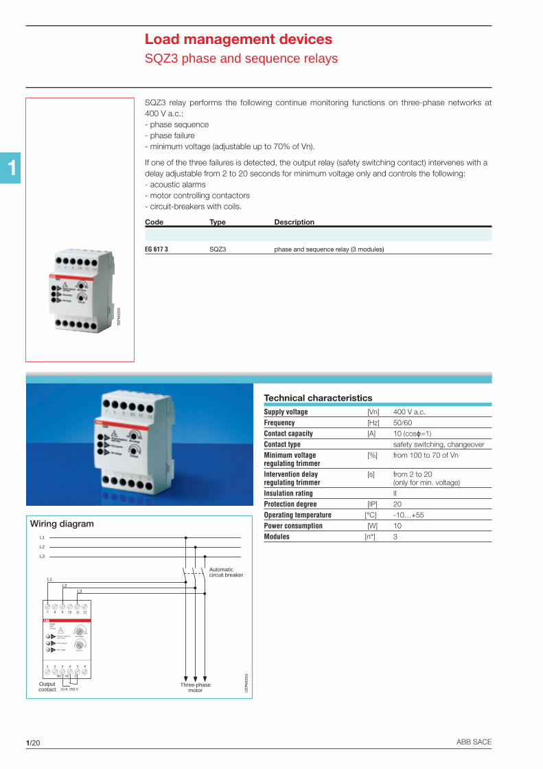
SQZ3 relay performs the following continue monitoring functions on three-phase networks at400 V a.c.:- phase sequence- phase failure- minimum voltage (adjustable up to 70% of Vn).
If one of the three failures is detected, the output relay (safety switching contact) intervenes with adelay adjustable from 2 to 20 seconds for minimum voltage only and controls the following:- acoustic alarms- motor controlling contactors- circuit-breakers with coils.
Code Type Description
EG 617 3 SQZ3 phase and sequence relay (3 modules)
Technical characteristicsSupply voltage [Vn] 400 V a.c.
Frequency [Hz] 50/60
Contact capacity [A] 10 (cosϕ=1)
Contact type safety switching, changeover
Minimum voltage [%] from 100 to 70 of Vnregulating trimmerIntervention delay [s] from 2 to 20regulating trimmer (only for min. voltage)
Insulation rating II
Protection degree [IP] 20
Operating temperature [°C] -10…+55
Power consumption [W] 10
Modules [n°] 3
TEP
M02
55
L1
L2
L3
Outputcontact
Three-phasemotor
Automaticcircuit breaker
7 8 9
1 2 3 4 5 6
SQZ3400V50-60Hz
10 11 12
Phases Sequence400V 50Hz
OK
OK
OK
Three phases
Min Voltage
Min Voltage
Delay (s)
70% 100%
2 20
NO NC C
L1L2
L3
10 A 250 V OE
PM
0055
Wiring diagram
1/21ABB SACE
1
Load management devicesLEE 230 power failure signalling extractable lamp
Technical characteristics2P 10 A plug distance between pins 19 mm,
pin ø 4 mm
Supply [V] 230 a.c., 50-60 Hz
Recharge time [h] 24
Endurance [h] 3
Lighting level [mcd] 3000
Operating temperature [°C] 0…+45
Min. life cycle 5 years (battery)
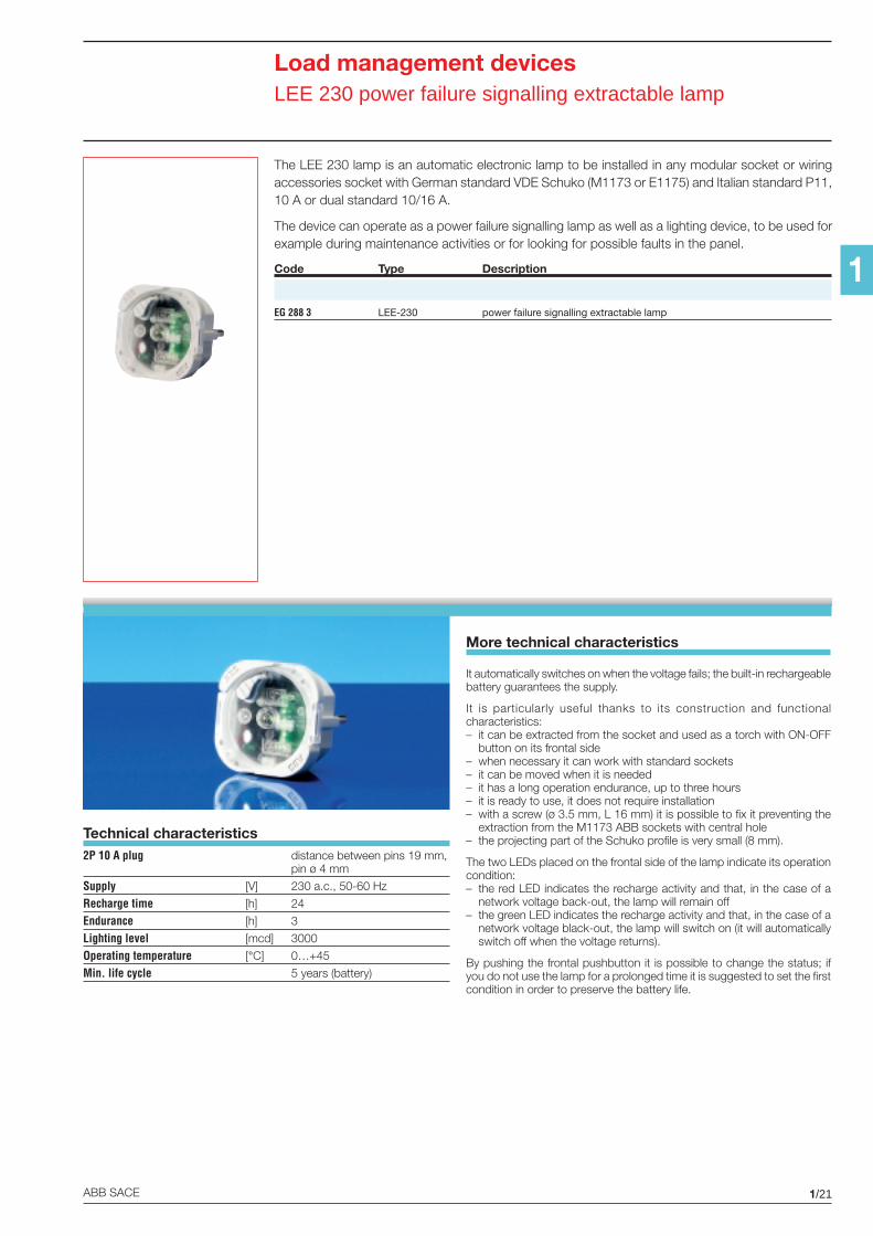
The LEE 230 lamp is an automatic electronic lamp to be installed in any modular socket or wiringaccessories socket with German standard VDE Schuko (M1173 or E1175) and Italian standard P11,10 A or dual standard 10/16 A.
The device can operate as a power failure signalling lamp as well as a lighting device, to be used forexample during maintenance activities or for looking for possible faults in the panel.
Code Type Description
EG 288 3 LEE-230 power failure signalling extractable lamp
It automatically switches on when the voltage fails; the built-in rechargeablebattery guarantees the supply.
It is particularly useful thanks to its construction and functionalcharacteristics:– it can be extracted from the socket and used as a torch with ON-OFF
button on its frontal side– when necessary it can work with standard sockets– it can be moved when it is needed– it has a long operation endurance, up to three hours– it is ready to use, it does not require installation– with a screw (ø 3.5 mm, L 16 mm) it is possible to fix it preventing the
extraction from the M1173 ABB sockets with central hole– the projecting part of the Schuko profile is very small (8 mm).
The two LEDs placed on the frontal side of the lamp indicate its operationcondition:– the red LED indicates the recharge activity and that, in the case of a
network voltage back-out, the lamp will remain off– the green LED indicates the recharge activity and that, in the case of a
network voltage black-out, the lamp will switch on (it will automaticallyswitch off when the voltage returns).
By pushing the frontal pushbutton it is possible to change the status; ifyou do not use the lamp for a prolonged time it is suggested to set the firstcondition in order to preserve the battery life.
More technical characteristics
1/22 ABB SACE
1
Load management devicesMax./min. current/voltage ammetric and voltmetric relays
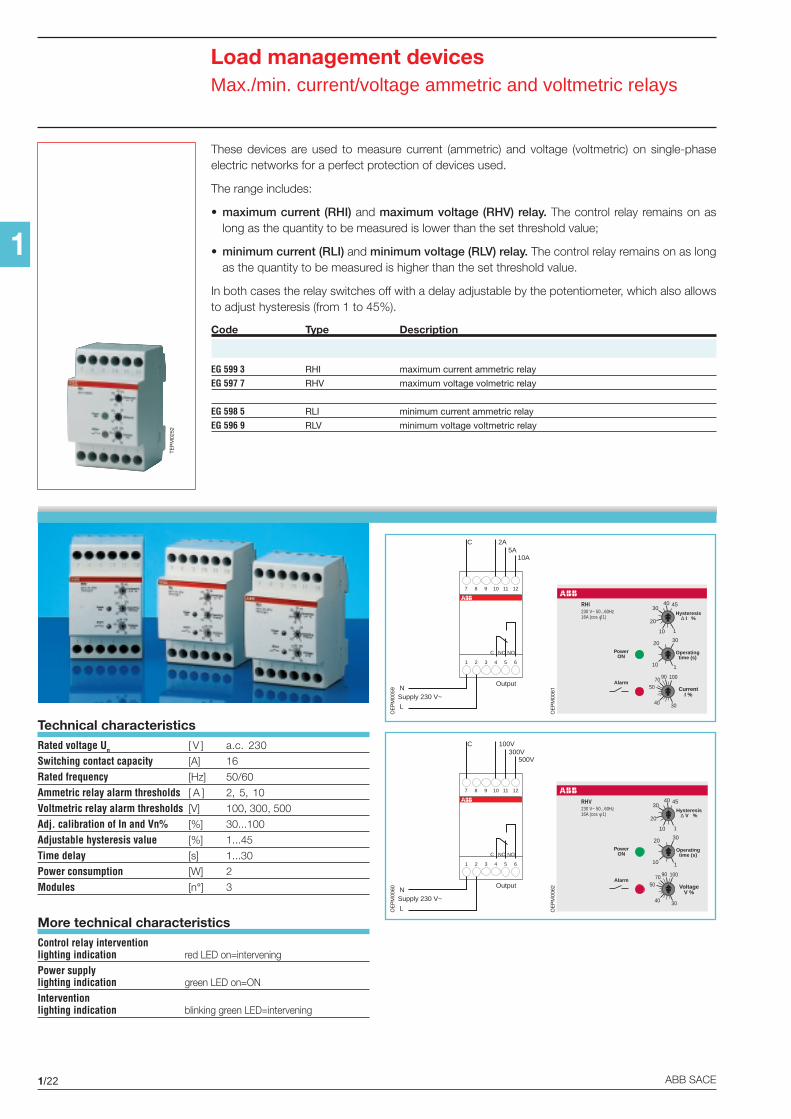
These devices are used to measure current (ammetric) and voltage (voltmetric) on single-phaseelectric networks for a perfect protection of devices used.
The range includes:
• maximum current (RHI) and maximum voltage (RHV) relay. The control relay remains on aslong as the quantity to be measured is lower than the set threshold value;
• minimum current (RLI) and minimum voltage (RLV) relay. The control relay remains on as longas the quantity to be measured is higher than the set threshold value.
In both cases the relay switches off with a delay adjustable by the potentiometer, which also allowsto adjust hysteresis (from 1 to 45%).
Code Type Description
EG 599 3 RHI maximum current ammetric relay
EG 597 7 RHV maximum voltage volmetric relay
EG 598 5 RLI minimum current ammetric relay
EG 596 9 RLV minimum voltage voltmetric relay
Technical characteristicsRated voltage Un [ V ] a.c. 230
Switching contact capacity [A] 16
Rated frequency [Hz] 50/60
Ammetric relay alarm thresholds [ A ] 2, 5, 10
Voltmetric relay alarm thresholds [V] 100, 300, 500
Adj. calibration of In and Vn% [%] 30...100
Adjustable hysteresis value [%] 1...45
Time delay [s] 1...30
Power consumption [W] 2
Modules [n°] 3
More technical characteristicsControl relay interventionlighting indication red LED on=intervening
Power supplylighting indication green LED on=ON
Interventionlighting indication blinking green LED=intervening
1 2 3 4 5 6
7 8 9 10 11 12
C NC NO
Output
100V300V
500V
C
N
L
Supply 230 V~
1 2 3 4 5 6
7 8 9 10 11 12
C NC NO
Output
2A5A
10A
C
N
L
Supply 230 V~
OE
PM
0060
OE
PM
0059
Hysteresis∆ I %
30
100
CurrentI %
40
5070 90
1
30
Operatingtime (s)
1
45
10
20
3040
20
10
PowerON
230 V~ 50...60Hz16A (cos 1)
Alarm
RHI
Hysteresis∆ V %
30
100
VoltageV %
40
5070 90
1
30
Operatingtime (s)
1
45
10
20
3040
20
10
PowerON
230 V~ 50...60Hz16A (cos 1)
Alarm
RHV
OE
PM
0062
OE
PM
0061
TEP
M02
52
1/23ABB SACE
1
Measurement devicesMeasurement instruments
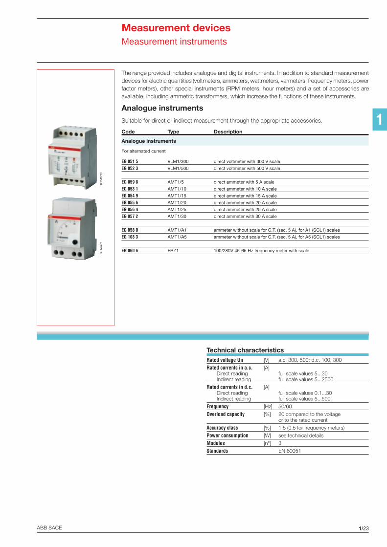
Technical characteristicsRated voltage Un [V] a.c. 300, 500; d.c. 100, 300
Rated currents in a.c. [A] Direct reading full scale values 5...30 Indirect reading full scale values 5...2500
Rated currents in d.c. [A] Direct reading full scale values 0.1...30 Indirect reading full scale values 5...500
Frequency [Hz] 50/60
Overload capacity [%] 20 compared to the voltageor to the rated current
Accuracy class [%] 1.5 (0.5 for frequency meters)
Power consumption [W] see technical details
Modules [n°] 3
Standards EN 60051
The range provided includes analogue and digital instruments. In addition to standard measurementdevices for electric quantities (voltmeters, ammeters, wattmeters, varmeters, frequency meters, powerfactor meters), other special instruments (RPM meters, hour meters) and a set of accessories areavailable, including ammetric transformers, which increase the functions of these instruments.
Analogue instruments
Suitable for direct or indirect measurement through the appropriate accessories.
Code Type Description
Analogue instruments
For alternated current
EG 051 5 VLM1/300 direct voltmeter with 300 V scale
EG 052 3 VLM1/500 direct voltmeter with 500 V scale
EG 059 8 AMT1/5 direct ammeter with 5 A scale
EG 053 1 AMT1/10 direct ammeter with 10 A scale
EG 054 9 AMT1/15 direct ammeter with 15 A scale
EG 055 6 AMT1/20 direct ammeter with 20 A scale
EG 056 4 AMT1/25 direct ammeter with 25 A scale
EG 057 2 AMT1/30 direct ammeter with 30 A scale
EG 058 0 AMT1/A1 ammeter without scale for C.T. (sec. 5 A), for A1 (SCL1) scales
EG 108 3 AMT1/A5 ammeter without scale for C.T. (sec. 5 A), for A5 (SCL1) scales
EG 060 6 FRZ1 100/280V 45-65 Hz frequency meter with scale
TEP
M02
70TE
PM
0271
1/24 ABB SACE
1
Measurement devicesMeasurement instruments
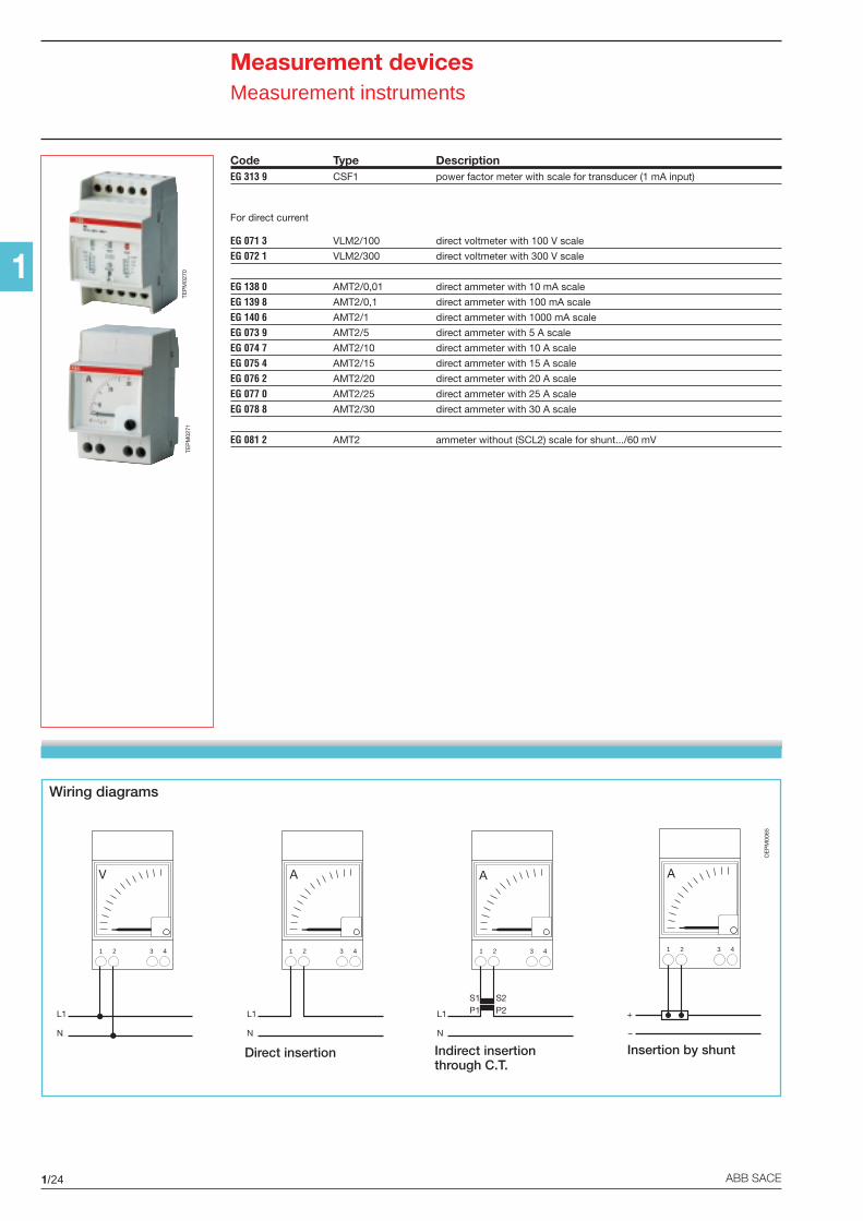
Code Type DescriptionEG 313 9 CSF1 power factor meter with scale for transducer (1 mA input)
For direct current
EG 071 3 VLM2/100 direct voltmeter with 100 V scale
EG 072 1 VLM2/300 direct voltmeter with 300 V scale
EG 138 0 AMT2/0,01 direct ammeter with 10 mA scale
EG 139 8 AMT2/0,1 direct ammeter with 100 mA scale
EG 140 6 AMT2/1 direct ammeter with 1000 mA scale
EG 073 9 AMT2/5 direct ammeter with 5 A scale
EG 074 7 AMT2/10 direct ammeter with 10 A scale
EG 075 4 AMT2/15 direct ammeter with 15 A scale
EG 076 2 AMT2/20 direct ammeter with 20 A scale
EG 077 0 AMT2/25 direct ammeter with 25 A scale
EG 078 8 AMT2/30 direct ammeter with 30 A scale
EG 081 2 AMT2 ammeter without (SCL2) scale for shunt.../60 mV
Wiring diagrams
Direct insertion Insertion by shuntIndirect insertionthrough C.T.
OE
PM
0065
1 2 3 4
+
–
A
1 2 3 4
L1
N
S1P1
S2P2
A
1 2 3 4
L1
N
A
1 2 3 4
L1
N
V
TEP
M02
70TE
PM
0271
1/25ABB SACE
1
Measurement devicesMeasurement instruments
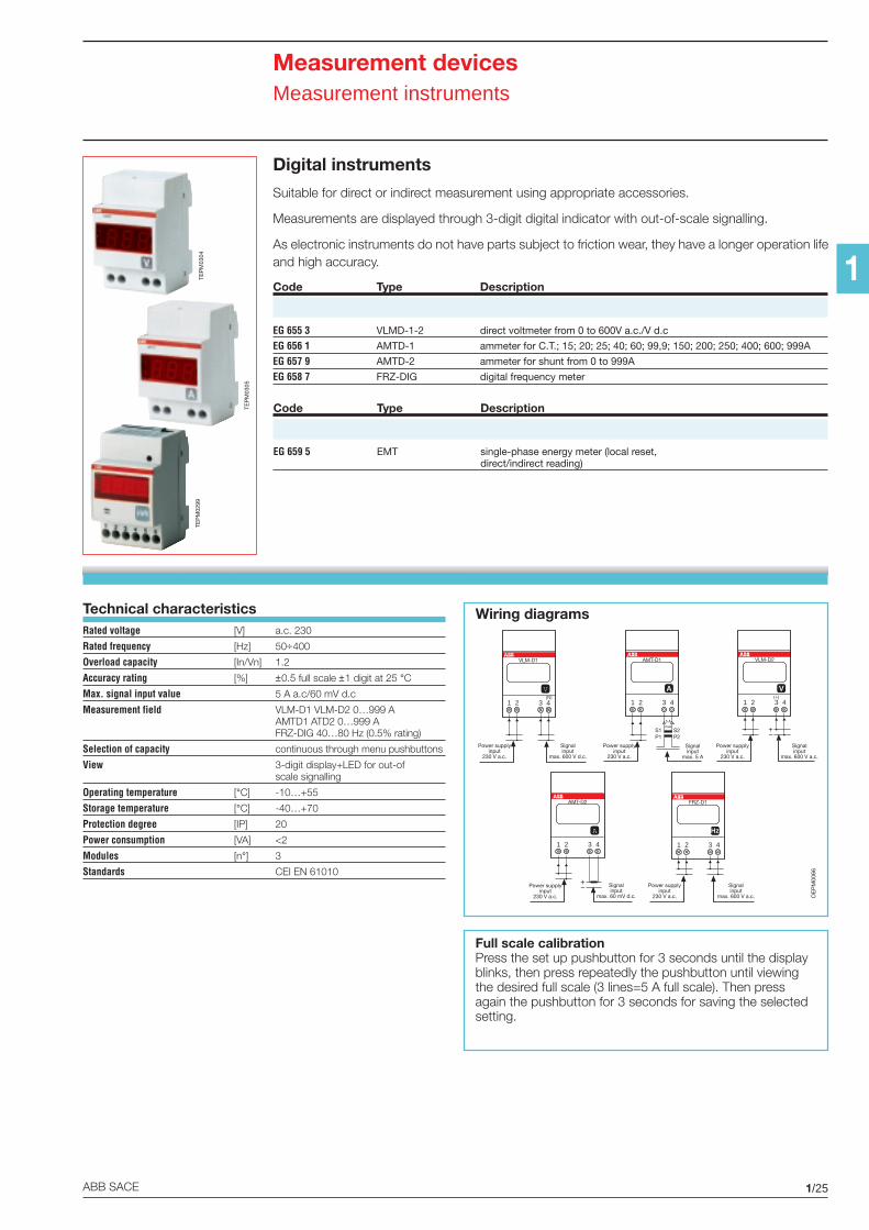
Digital instruments
Suitable for direct or indirect measurement using appropriate accessories.
Measurements are displayed through 3-digit digital indicator with out-of-scale signalling.
As electronic instruments do not have parts subject to friction wear, they have a longer operation lifeand high accuracy.
Code Type Description
EG 655 3 VLMD-1-2 direct voltmeter from 0 to 600V a.c./V d.c
EG 656 1 AMTD-1 ammeter for C.T.; 15; 20; 25; 40; 60; 99,9; 150; 200; 250; 400; 600; 999A
EG 657 9 AMTD-2 ammeter for shunt from 0 to 999A
EG 658 7 FRZ-DIG digital frequency meter
TEP
M03
04
TEP
M03
05
Technical characteristicsRated voltage [V] a.c. 230
Rated frequency [Hz] 50÷400
Overload capacity [In/Vn] 1.2
Accuracy rating [%] ±0.5 full scale ±1 digit at 25 °CMax. signal input value 5 A a.c/60 mV d.c
Measurement field VLM-D1 VLM-D2 0…999 AAMTD1 ATD2 0…999 AFRZ-DIG 40…80 Hz (0.5% rating)
Selection of capacity continuous through menu pushbuttons
View 3-digit display+LED for out-ofscale signalling
Operating temperature [°C] -10…+55
Storage temperature [°C] -40…+70
Protection degree [IP] 20
Power consumption [VA] <2
Modules [n°] 3
Standards CEI EN 61010
OE
PM
0066
Wiring diagrams
Full scale calibrationPress the set up pushbutton for 3 seconds until the displayblinks, then press repeatedly the pushbutton until viewingthe desired full scale (3 lines=5 A full scale). Then pressagain the pushbutton for 3 seconds for saving the selectedsetting.
TEP
M02
99
Code Type Description
EG 659 5 EMT single-phase energy meter (local reset,direct/indirect reading)
Hz
1 2 3 4
FRZ-D1
Power supplyinput
230 V a.c.
Signalinput
max. 600 V a.c.
V
1 2 3 4
VLM-D2
(+)
Power supplyinput
230 V a.c.
Signalinput
max. 600 V a.c.
V
1 2 3 4
VLM-D1
(N)
Power supplyinput
230 V a.c.
Signalinput
max. 600 V d.c.
A
1 2 3 4
AMT-D2
Signalinput
max. 60 mV d.c.
Power supplyinput
230 V a.c.
A
1 2 3 4
AMT-D1
5 Amax
S1 S2P1 P2
Power supplyinput
230 V a.c.
Signalinput
max. 5 A
1/26 ABB SACE
1
Measurement devicesMeasurement instruments
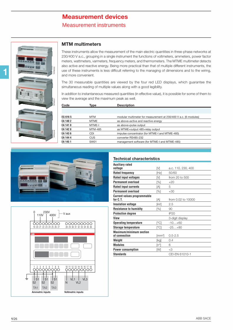
MTM multimeters
These instruments allow the measurement of the main electric quantities in three-phase networks at230/400 V a.c., grouping in a single instrument the functions of voltmeters, ammeters, power factormeters, wattmeters, varmeters, frequency meters, and thermometers. The MTME multimeter detectsalso active and reactive energy. Being more practical than that of multiple different instruments, theuse of these instruments is less difficult referring to the managing of dimensions and to the wiring,and more convenient.
The 30 measurable quantities are viewed by the four red LED displays, which guarantee thesimultaneous reading of multiple values along with a good legibility.
In addition to instantaneous measured quantities (in effective value), it is possible for some of them toview the average and the maximum peak as well.
Code Type Description
EG 616 5 MTM modular multimeter for measurement at 230/400 V a.c. (6 modules)
EA 140 2 MTME as above+active and reactive energy
EA 141 0 MTME-I as above+pulse output
EA 142 8 MTM-485 as MTME+output 485+relay output
EA 143 6 CDI impulse concentrator (for MTME-I and MTME-485)
EA 144 4 CUS converter RS485-232
EA 145 1 SW01 management software (for MTME-I and MTME-485)
TEP
M03
32
TA2 TA3TA1
19 20 21 22 23 24 25 26 27 28 29 30 31 32 33 34 35 36
1 2 3 4 5 6 7 8 9 10 11 12 13 14 15 16 17 18
110V 400V230V0
S2S1
S2S1
S2S1
NVL1 VL3
VL2
V aux
Ammetric inputs Voltmetric inputs
Technical characteristicsAuxiliary ratedvoltage [V] a.c. 110, 230, 400
Rated frequency [Hz] 50/60
Rated input voltages [V] from 20 to 500
Permanent overload [%] +20
Rated input currents [A] 5
Permanent overload [%] +30
Current values programmablefor C.T. [A] from 0.02 to 10000
Insulation voltage [kV] 2.5
Resistance to humidity [%] 90
Protection degree IP20
View 3-digit display
Operating temperature [°C] -10…+60
Storage temperature [°C] -25…+80
Maximum/minimum sectionof connection [mm2] 0.5-2.5
Weight [kg] 0.4
Modules [n°] 6
Power consumption [W] <3
Standards CEI-EN 61010-1
TEP
M04
47TE
PM
0448
1/27ABB SACE
1
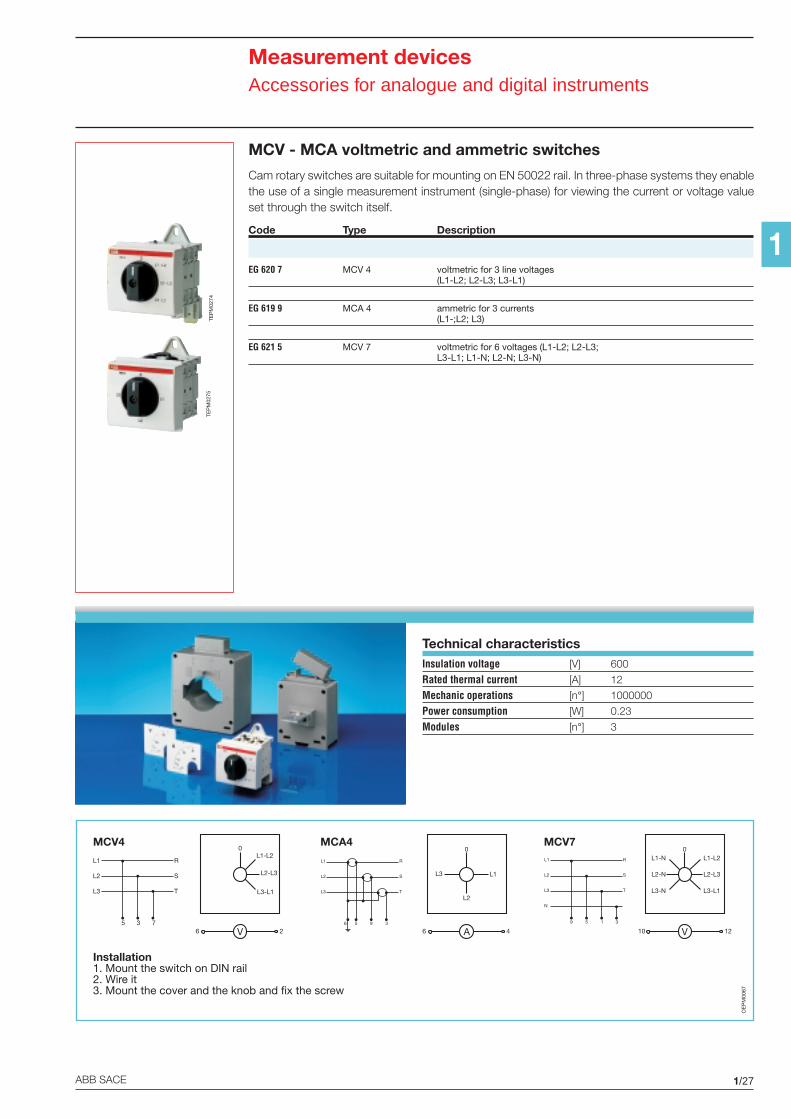
MCV - MCA voltmetric and ammetric switches
Cam rotary switches are suitable for mounting on EN 50022 rail. In three-phase systems they enablethe use of a single measurement instrument (single-phase) for viewing the current or voltage valueset through the switch itself.
Code Type Description
EG 620 7 MCV 4 voltmetric for 3 line voltages(L1-L2; L2-L3; L3-L1)
EG 619 9 MCA 4 ammetric for 3 currents(L1-;L2; L3)
EG 621 5 MCV 7 voltmetric for 6 voltages (L1-L2; L2-L3;L3-L1; L1-N; L2-N; L3-N)
TEP
M02
75TE
PM
0274
L1
L2
L3
R
S
T
5 3 7
L1
L2
L3
R
S
T
6 5 9 3
N
3
L1
L2
L3
R
S
T
9 5 1
V
L1-L2
L2-L3
L3-L1
6 2
0
A
0
L1
L2
6 4
L3
V
0L1-L2
10 12
L2-L3
L3-L1
L1-N
L2-N
L3-N
MCV4 MCA4 MCV7
Installation1. Mount the switch on DIN rail2. Wire it3. Mount the cover and the knob and fix the screw
OE
PM
0067
Technical characteristicsInsulation voltage [V] 600
Rated thermal current [A] 12
Mechanic operations [n°] 1000000
Power consumption [W] 0.23
Modules [n°] 3
Measurement devicesAccessories for analogue and digital instruments
1/28 ABB SACE
1
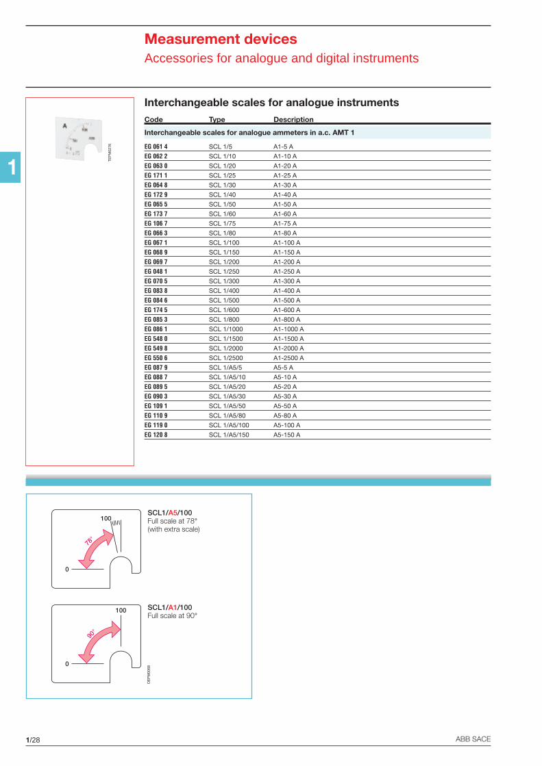
Measurement devicesAccessories for analogue and digital instruments
0
100
78°
0
100
90°
SCL1/A5/100Full scale at 78°(with extra scale)
SCL1/A1/100Full scale at 90°
OE
PM
0068
Interchangeable scales for analogue instrumentsCode Type Description
Interchangeable scales for analogue ammeters in a.c. AMT 1
EG 061 4 SCL 1/5 A1-5 A
EG 062 2 SCL 1/10 A1-10 A
EG 063 0 SCL 1/20 A1-20 A
EG 171 1 SCL 1/25 A1-25 A
EG 064 8 SCL 1/30 A1-30 A
EG 172 9 SCL 1/40 A1-40 A
EG 065 5 SCL 1/50 A1-50 A
EG 173 7 SCL 1/60 A1-60 A
EG 106 7 SCL 1/75 A1-75 A
EG 066 3 SCL 1/80 A1-80 A
EG 067 1 SCL 1/100 A1-100 A
EG 068 9 SCL 1/150 A1-150 A
EG 069 7 SCL 1/200 A1-200 A
EG 048 1 SCL 1/250 A1-250 A
EG 070 5 SCL 1/300 A1-300 A
EG 083 8 SCL 1/400 A1-400 A
EG 084 6 SCL 1/500 A1-500 A
EG 174 5 SCL 1/600 A1-600 A
EG 085 3 SCL 1/800 A1-800 A
EG 086 1 SCL 1/1000 A1-1000 A
EG 548 0 SCL 1/1500 A1-1500 A
EG 549 8 SCL 1/2000 A1-2000 A
EG 550 6 SCL 1/2500 A1-2500 A
EG 087 9 SCL 1/A5/5 A5-5 A
EG 088 7 SCL 1/A5/10 A5-10 A
EG 089 5 SCL 1/A5/20 A5-20 A
EG 090 3 SCL 1/A5/30 A5-30 A
EG 109 1 SCL 1/A5/50 A5-50 A
EG 110 9 SCL 1/A5/80 A5-80 A
EG 119 0 SCL 1/A5/100 A5-100 A
EG 120 8 SCL 1/A5/150 A5-150 A
TEP
M02
76

1/29ABB SACE
1
Measurement devicesAccessories for analogue and digital instruments
Interchangeable scales for analogue ammeters in d.c. AMT 2
EG 082 0 SCL 2/5 A1-5 A
EG 079 6 SCL 2/6 A1-6 A
EG 080 4 SCL 2/10 A1-10 A
EG 149 7 SCL 2/20 A1-20 A
EG 150 5 SCL 2/30 A1-30 A
EG 193 5 SCL 2/50 A1-50 A
EG 194 3 SCL 2/80 A1-80 A
EG 195 0 SCL 2/100 A1-100 A
EG 196 8 SCL 2/150 A1-150 A
EG 197 6 SCL 2/200 A1-200 A
EG 198 4 SCL 2/250 A1-250 A
EG 199 2 SCL 2/300 A1-300 A
EG 102 6 SCL 2/400 A1-400 A
EG 103 4 SCL 2/500 A1-500 A
TEP
M02
77
1/30 ABB SACE
1
Measurement devicesAccessories for analogue and digital instruments
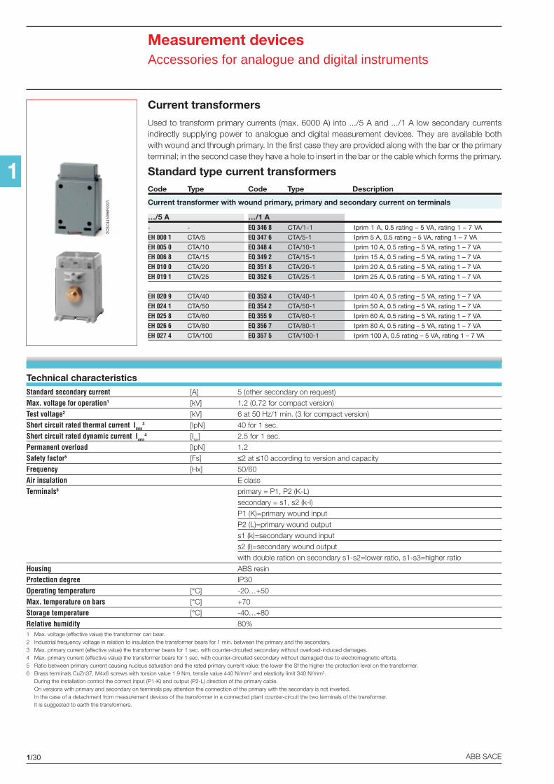
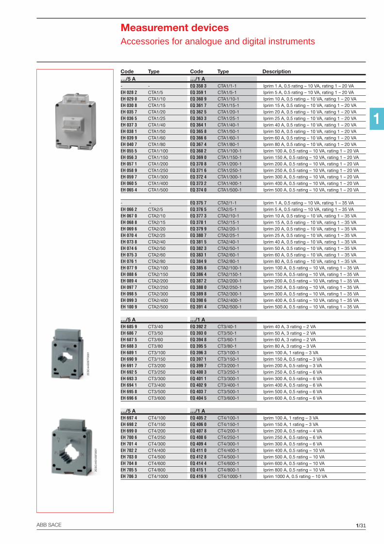
Current transformers
Used to transform primary currents (max. 6000 A) into .../5 A and .../1 A low secondary currentsindirectly supplying power to analogue and digital measurement devices. They are available bothwith wound and through primary. In the first case they are provided along with the bar or the primaryterminal; in the second case they have a hole to insert in the bar or the cable which forms the primary.
Technical characteristicsStandard secondary current [A] 5 (other secondary on request)
Max. voltage for operation1 [kV] 1.2 (0.72 for compact version)
Test voltage2 [kV] 6 at 50 Hz/1 min. (3 for compact version)
Short circuit rated thermal current Imin3 [IpN] 40 for 1 sec.
Short circuit rated dynamic current Imin4 [Iter] 2.5 for 1 sec.
Permanent overload [IpN] 1.2
Safety factor5 [Fs] ≤2 at ≤10 according to version and capacity
Frequency [Hx] 50/60
Air insulation E class
Terminals6 primary = P1, P2 (K-L)
secondary = s1, s2 (k-l)
P1 (K)=primary wound input
P2 (L)=primary wound output
s1 (k)=secondary wound input
s2 (l)=secondary wound output
with double ration on secondary s1-s2=lower ratio, s1-s3=higher ratio
Housing ABS resin
Protection degree IP30
Operating temperature [°C] -20…+50
Max. temperature on bars [°C] +70
Storage temperature [°C] -40…+80
Relative humidity 80%1 Max. voltage (effective value) the transformer can bear.2 Industrial frequency voltage in relation to insulation the transformer bears for 1 min. between the primary and the secondary.3 Max. primary current (effective value) the transformer bears for 1 sec. with counter-circuited secondary without overload-induced damages.4 Max. primary current (effective value) the transformer bears for 1 sec. with counter-circuited secondary without damaged due to electromagnetic efforts.5 Ratio between primary current causing nucleus saturation and the rated primary current value: the lower the Sf the higher the protection level on the transformer.6 Brass terminals CuZn37, M4x6 screws with torsion value 1.9 Nm, tensile value 440 N/mm2 and elasticity limit 340 N/mm2.
During the installation control the correct input (P1-K) and output (P2-L) direction of the primary cable.On versions with primary and secondary on terminals pay attention the connection of the primary with the secondary is not inverted.In the case of a detachment from measurement devices of the transformer in a connected plant counter-circuit the two terminals of the transformer.It is suggested to earth the transformers.
Standard type current transformersCode Type Code Type Description
Current transformer with wound primary, primary and secondary current on terminals
…/5 A …/1 A- - EQ 346 8 CTA/1-1 Iprim 1 A, 0.5 rating – 5 VA, rating 1 – 7 VA
EH 000 1 CTA/5 EQ 347 6 CTA/5-1 Iprim 5 A, 0.5 rating – 5 VA, rating 1 – 7 VA
EH 005 0 CTA/10 EQ 348 4 CTA/10-1 Iprim 10 A, 0.5 rating – 5 VA, rating 1 – 7 VA
EH 006 8 CTA/15 EQ 349 2 CTA/15-1 Iprim 15 A, 0.5 rating – 5 VA, rating 1 – 7 VA
EH 010 0 CTA/20 EQ 351 8 CTA/20-1 Iprim 20 A, 0.5 rating – 5 VA, rating 1 – 7 VA
EH 019 1 CTA/25 EQ 352 6 CTA/25-1 Iprim 25 A, 0.5 rating – 5 VA, rating 1 – 7 VA
EH 020 9 CTA/40 EQ 353 4 CTA/40-1 Iprim 40 A, 0.5 rating – 5 VA, rating 1 – 7 VA
EH 024 1 CTA/50 EQ 354 2 CTA/50-1 Iprim 50 A, 0.5 rating – 5 VA, rating 1 – 7 VA
EH 025 8 CTA/60 EQ 355 9 CTA/60-1 Iprim 60 A, 0.5 rating – 5 VA, rating 1 – 7 VA
EH 026 6 CTA/80 EQ 356 7 CTA/80-1 Iprim 80 A, 0.5 rating – 5 VA, rating 1 – 7 VA
EH 027 4 CTA/100 EQ 357 5 CTA/100-1 Iprim 100 A, 0.5 rating – 5 VA, rating 1 – 7 VA
2CS
C44
5096
F00
01
1/31ABB SACE
1
Measurement devicesAccessories for analogue and digital instruments
Code Type Code Type Description…/5 A …/1 A- - EQ 358 3 CTA1/1-1 Iprim 1 A, 0.5 rating – 10 VA, rating 1 – 20 VAEH 028 2 CTA1/5 EQ 359 1 CTA1/5-1 Iprim 5 A, 0.5 rating – 10 VA, rating 1 – 20 VAEH 029 0 CTA1/10 EQ 360 9 CTA1/10-1 Iprim 10 A, 0.5 rating – 10 VA, rating 1 – 20 VAEH 030 8 CTA1/15 EQ 361 7 CTA1/15-1 Iprim 15 A, 0.5 rating – 10 VA, rating 1 – 20 VAEH 035 7 CTA1/20 EQ 362 5 CTA1/20-1 Iprim 20 A, 0.5 rating – 10 VA, rating 1 – 20 VAEH 036 5 CTA1/25 EQ 363 3 CTA1/25-1 Iprim 25 A, 0.5 rating – 10 VA, rating 1 – 20 VAEH 037 3 CTA1/40 EQ 364 1 CTA1/40-1 Iprim 40 A, 0.5 rating – 10 VA, rating 1 – 20 VAEH 038 1 CTA1/50 EQ 365 8 CTA1/50-1 Iprim 50 A, 0.5 rating – 10 VA, rating 1 – 20 VAEH 039 9 CTA1/60 EQ 366 6 CTA1/60-1 Iprim 60 A, 0.5 rating – 10 VA, rating 1 – 20 VAEH 040 7 CTA1/80 EQ 367 4 CTA1/80-1 Iprim 80 A, 0.5 rating – 10 VA, rating 1 – 20 VAEH 055 5 CTA1/100 EQ 368 2 CTA1/100-1 Iprim 100 A, 0.5 rating – 10 VA, rating 1 – 20 VAEH 056 3 CTA1/150 EQ 369 0 CTA1/150-1 Iprim 150 A, 0.5 rating – 10 VA, rating 1 – 20 VAEH 057 1 CTA1/200 EQ 370 8 CTA1/200-1 Iprim 200 A, 0.5 rating – 10 VA, rating 1 – 20 VAEH 058 9 CTA1/250 EQ 371 6 CTA1/250-1 Iprim 250 A, 0.5 rating – 10 VA, rating 1 – 20 VAEH 059 7 CTA1/300 EQ 372 4 CTA1/300-1 Iprim 300 A, 0.5 rating – 10 VA, rating 1 – 20 VAEH 060 5 CTA1/400 EQ 373 2 CTA1/400-1 Iprim 400 A, 0.5 rating – 10 VA, rating 1 – 20 VAEH 065 4 CTA1/500 EQ 374 0 CTA1/500-1 Iprim 500 A, 0.5 rating – 10 VA, rating 1 – 20 VA
- - EQ 375 7 CTA2/1-1 Iprim 1 A, 0.5 rating – 10 VA, rating 1 – 35 VAEH 066 2 CTA2/5 EQ 376 5 CTA2/5-1 Iprim 5 A, 0.5 rating – 10 VA, rating 1 – 35 VAEH 067 0 CTA2/10 EQ 377 3 CTA2/10-1 Iprim 10 A, 0.5 rating – 10 VA, rating 1 – 35 VAEH 068 8 CTA2/15 EQ 378 1 CTA2/15-1 Iprim 15 A, 0.5 rating – 10 VA, rating 1 – 35 VAEH 069 6 CTA2/20 EQ 379 9 CTA2/20-1 Iprim 20 A, 0.5 rating – 10 VA, rating 1 – 35 VAEH 070 4 CTA2/25 EQ 380 7 CTA2/25-1 Iprim 25 A, 0.5 rating – 10 VA, rating 1 – 35 VAEH 073 8 CTA2/40 EQ 381 5 CTA2/40-1 Iprim 40 A, 0.5 rating – 10 VA, rating 1 – 35 VAEH 074 6 CTA2/50 EQ 382 3 CTA2/50-1 Iprim 50 A, 0.5 rating – 10 VA, rating 1 – 35 VAEH 075 3 CTA2/60 EQ 383 1 CTA2/60-1 Iprim 60 A, 0.5 rating – 10 VA, rating 1 – 35 VAEH 076 1 CTA2/80 EQ 384 9 CTA2/80-1 Iprim 80 A, 0.5 rating – 10 VA, rating 1 – 35 VAEH 077 9 CTA2/100 EQ 385 6 CTA2/100-1 Iprim 100 A, 0.5 rating – 10 VA, rating 1 – 35 VAEH 088 6 CTA2/150 EQ 386 4 CTA2/150-1 Iprim 150 A, 0.5 rating – 10 VA, rating 1 – 35 VAEH 089 4 CTA2/200 EQ 387 2 CTA2/200-1 Iprim 200 A, 0.5 rating – 10 VA, rating 1 – 35 VAEH 097 7 CTA2/250 EQ 388 0 CTA2/250-1 Iprim 250 A, 0.5 rating – 10 VA, rating 1 – 35 VAEH 098 5 CTA2/300 EQ 389 8 CTA2/300-1 Iprim 300 A, 0.5 rating – 10 VA, rating 1 – 35 VAEH 099 3 CTA2/400 EQ 390 6 CTA2/400-1 Iprim 400 A, 0.5 rating – 10 VA, rating 1 – 35 VAEH 100 9 CTA2/500 EQ 391 4 CTA2/500-1 Iprim 500 A, 0.5 rating – 10 VA, rating 1 – 35 VA
…/5 A …/1 AEH 685 9 CT3/40 EQ 392 2 CT3/40-1 Iprim 40 A, 3 rating – 2 VAEH 686 7 CT3/50 EQ 393 0 CT3/50-1 Iprim 50 A, 3 rating – 2 VAEH 687 5 CT3/60 EQ 394 8 CT3/60-1 Iprim 60 A, 3 rating – 2 VAEH 688 3 CT3/80 EQ 395 5 CT3/80-1 Iprim 80 A, 3 rating – 3 VAEH 689 1 CT3/100 EQ 396 3 CT3/100-1 Iprim 100 A, 1 rating – 3 VAEH 690 9 CT3/150 EQ 397 1 CT3/150-1 Iprim 150 A, 0.5 rating – 3 VAEH 691 7 CT3/200 EQ 399 7 CT3/200-1 Iprim 200 A, 0.5 rating – 3 VAEH 692 5 CT3/250 EQ 400 3 CT3/250-1 Iprim 250 A, 0.5 rating – 6 VAEH 693 3 CT3/300 EQ 401 1 CT3/300-1 Iprim 300 A, 0.5 rating – 6 VAEH 694 1 CT3/400 EQ 402 9 CT3/400-1 Iprim 400 A, 0.5 rating – 6 VAEH 695 8 CT3/500 EQ 403 7 CT3/500-1 Iprim 500 A, 0.5 rating – 6 VAEH 696 6 CT3/600 EQ 404 5 CT3/600-1 Iprim 600 A, 0.5 rating – 6 VA
…/5 A …/1 AEH 697 4 CT4/100 EQ 405 2 CT4/100-1 Iprim 100 A, 1 rating – 3 VAEH 698 2 CT4/150 EQ 406 0 CT4/150-1 Iprim 150 A, 1 rating – 3 VAEH 699 0 CT4/200 EQ 407 8 CT4/200-1 Iprim 200 A, 0.5 rating – 4 VAEH 700 6 CT4/250 EQ 408 6 CT4/250-1 Iprim 250 A, 0.5 rating – 6 VAEH 701 4 CT4/300 EQ 409 4 CT4/300-1 Iprim 300 A, 0.5 rating – 6 VAEH 702 2 CT4/400 EQ 411 0 CT4/400-1 Iprim 400 A, 0.5 rating – 10 VAEH 703 0 CT4/500 EQ 412 8 CT4/500-1 Iprim 500 A, 0.5 rating – 10 VAEH 704 8 CT4/600 EQ 414 4 CT4/600-1 Iprim 600 A, 0.5 rating – 10 VAEH 705 5 CT4/800 EQ 415 1 CT4/800-1 Iprim 800 A, 0.5 rating – 10 VAEH 706 3 CT4/1000 EQ 416 9 CT4/1000-1 Iprim 1000 A, 0.5 rating – 10 VA
2CS
C44
5105
F00
01
2CS
C44
5097
F00
01

1/32 ABB SACE
1
Measurement devicesAccessories for analogue and digital instruments
Code Type Code Type Description…/5 A …/1 AEH 707 1 CT5/250 EQ 417 7 CT5/250-1 Iprim 250 A, 0.5 rating – 3 VAEH 708 9 CT5/300 EQ 418 5 CT5/300-1 Iprim 300 A, 0.5 rating – 4 VAEH 709 7 CT5/400 EQ 419 3 CT5/400-1 Iprim 400 A, 0.5 rating – 6 VAEH 710 5 CT5/500 EQ 420 1 CT5/500-1 Iprim 500 A, 0.5 rating – 10 VAEH 711 3 CT5/600 EQ 421 9 CT5/600-1 Iprim 600 A, 0.5 rating – 10 VAEH 712 1 CT5/800 EQ 422 7 CT5/800-1 Iprim 800 A, 0.5 rating – 10 VAEH 713 9 CT5/1000 EQ 423 5 CT5/1000-1 Iprim 1000 A, 0.5 rating – 10 VAEH 714 7 CT5/1200 EQ 424 3 CT5/1200-1 Iprim 1200 A, 0.5 rating – 10 VAEH 715 4 CT5/1500 EQ 425 0 CT5/1500-1 Iprim 1500 A, 0.5 rating – 20 VA
…/5 A …/1 AEH 716 2 CT6/250 EQ 426 8 CT6/250-1 Iprim 250 A, 0.5 rating – 5 VAEH 717 0 CT6/300 EQ 427 6 CT6/300-1 Iprim 300 A, 0.5 rating – 5 VAEH 718 8 CT6/400 EQ 428 4 CT6/400-1 Iprim 400 A, 0.5 rating – 6 VAEH 719 6 CT6/500 EQ 429 2 CT6/500-1 Iprim 500 A, 0.5 rating – 6 VAEH 720 4 CT6/600 EQ 430 0 CT6/600-1 Iprim 600 A, 0.5 rating – 10 VAEH 721 2 CT6/800 EQ 431 8 CT6/800-1 Iprim 800 A, 0.5 rating – 10 VAEH 722 0 CT6/1000 EQ 432 6 CT6/1000-1 Iprim 1000 A, 0.5 rating – 20 VAEH 723 8 CT6/1200 EQ 433 4 CT6/1200-1 Iprim 1200 A, 0.5 rating – 20 VAEH 724 6 CT6/1500 EQ 434 2 CT6/1500-1 Iprim 1500 A, 0.5 rating – 30 VAEH 725 3 CT6/2000 EQ 435 9 CT6/2000-1 Iprim 2000 A, 0.5 rating – 30 VAEH 726 1 CT6/2500 EQ 436 7 CT6/2500-1 Iprim 2500 A, 0.5 rating – 30 VA
…/5 A …/1 AEH 727 9 CT8/300 EQ 437 5 CT8/300-1 Iprim 300 A, 0.5 rating – 5 VAEH 728 7 CT8/400 EQ 438 3 CT8/400-1 Iprim 400 A, 0.5 rating – 6 VAEH 729 5 CT8/500 EQ 439 1 CT8/500-1 Iprim 500 A, 0.5 rating – 10 VAEH 730 3 CT8/600 EQ 441 7 CT8/600-1 Iprim 600 A, 0.5 rating – 10 VAEH 731 1 CT8/800 EQ 442 5 CT8/800-1 Iprim 800 A, 0.5 rating – 10 VAEH 732 9 CT8/1000 EQ 443 3 CT8/1000-1 Iprim 1000 A, 0.5 rating – 10 VAEH 733 7 CT8/1200 EQ 444 1 CT8/1200-1 Iprim 1200 A, 0.5 rating – 15 VAEH 734 5 CT8/1500 EQ 445 8 CT8/1500-1 Iprim 1500 A, 0.5 rating – 20 VAEH 735 2 CT8/2000 EQ 446 6 CT8/2000-1 Iprim 2000 A, 0.5 rating – 20 VAEH 736 0 CT8/2500 EQ 447 4 CT8/2500-1 Iprim 2500 A, 0.5 rating – 20 VAEH 737 8 CT8/3000 EQ 448 2 CT8/3000-1 Iprim 3000 A, 0.5 rating – 20 VA
…/5 A …/1 AEH 748 5 CT8-V/400 EQ 449 0 CT8-V/400-1 Iprim 400 A, 0.5 rating – 6 VAEH 749 3 CT8-V/500 EQ 450 8 CT8-V/500-1 Iprim 500 A, 0.5 rating – 10 VAEH 750 1 CT8-V/600 EQ 451 6 CT8-V/600-1 Iprim 600 A, 0.5 rating – 10 VAEH 751 9 CT8-V/800 EQ 452 4 CT8-V/800-1 Iprim 800 A, 0.5 rating – 10 VAEH 752 7 CT8-V/1000 EQ 453 2 CT8-V/1000-1 Iprim 1000 A, 0.5 rating – 10 VAEH 753 5 CT8-V/1200 EQ 454 0 CT8-V/1200-1 Iprim 1200 A, 0.5 rating – 10 VAEH 754 3 CT8-V/1500 EQ 456 5 CT8-V/1500-1 Iprim 1500 A, 0.5 rating – 10 VAEH 755 0 CT8-V/2000 EQ 457 3 CT8-V/2000-1 Iprim 2000 A, 0.5 rating – 20 VAEH 756 8 CT8-V/2500 EQ 458 1 CT8-V/2500-1 Iprim 2500 A, 0.5 rating – 20 VA
…/5 A …/1 AEH 738 6 CT12/500 EQ 459 9 CT12/500-1 Iprim 500 A, 0.5 rating – 10 VAEH 739 4 CT12/600 EQ 460 7 CT12/600-1 Iprim 600 A, 0.5 rating – 10 VAEH 740 2 CT12/800 EQ 461 5 CT12/800-1 Iprim 800 A, 0.5 rating – 15 VAEH 741 0 CT12/1000 EQ 463 1 CT12/1000-1 Iprim 1000 A, 0.5 rating – 20 VAEH 742 8 CT12/1200 EQ 464 9 CT12/1200-1 Iprim 1200 A, 0.5 rating – 20 VAEH 743 6 CT12/1500 EQ 465 6 CT12/1500-1 Iprim 1500 A, 0.5 rating – 20 VAEH 744 4 CT12/2000 EQ 466 4 CT12/2000-1 Iprim 2000 A, 0.5 rating – 30 VAEH 745 1 CT12/2500 EQ 467 2 CT12/2500-1 Iprim 2500 A, 0.5 rating – 40 VAEH 746 9 CT12/3000 EQ 469 8 CT12/3000-1 Iprim 3000 A, 0.5 rating – 40 VAEH 747 7 CT12/4000 EQ 470 6 CT12/4000-1 Iprim 4000 A, 0.5 rating – 50 VAEH 884 8 CT12/5000 EQ 471 4 CT12/5000-1 Iprim 5000 A, 0.5 rating – 50 VAEH 891 3 CT12/6000 EQ 472 2 CT12/6000-1 Iprim 6000 A, 0.5 rating – 50 VA
2CS
C44
5098
F00
01
2CS
C44
5101
F00
012C
SC
4451
04F
0001
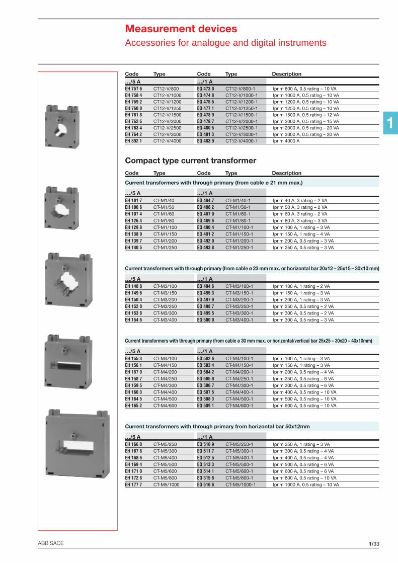
1/33ABB SACE
1
Measurement devicesAccessories for analogue and digital instruments
Code Type Code Type Description…/5 A …/1 AEH 757 6 CT12-V/800 EQ 473 0 CT12-V/800-1 Iprim 800 A, 0.5 rating – 10 VAEH 758 4 CT12-V/1000 EQ 474 8 CT12-V/1000-1 Iprim 1000 A, 0.5 rating – 10 VAEH 759 2 CT12-V/1200 EQ 475 5 CT12-V/1200-1 Iprim 1200 A, 0.5 rating – 10 VAEH 760 0 CT12-V/1250 EQ 477 1 CT12-V/1250-1 Iprim 1250 A, 0.5 rating – 10 VAEH 761 8 CT12-V/1500 EQ 478 9 CT12-V/1500-1 Iprim 1500 A, 0.5 rating – 12 VAEH 762 6 CT12-V/2000 EQ 479 7 CT12-V/2000-1 Iprim 2000 A, 0.5 rating – 15 VAEH 763 4 CT12-V/2500 EQ 480 5 CT12-V/2500-1 Iprim 2000 A, 0.5 rating – 20 VAEH 764 2 CT12-V/3000 EQ 481 3 CT12-V/3000-1 Iprim 3000 A, 0.5 rating – 20 VAEH 892 1 CT12-V/4000 EQ 483 9 CT12-V/4000-1 Iprim 4000 A
Compact type current transformerCode Type Code Type Description
Current transformers with through primary (from cable ø 21 mm max.)
…/5 A …/1 AEH 101 7 CT-M1/40 EQ 484 7 CT-M1/40-1 Iprim 40 A, 3 rating – 2 VAEH 106 6 CT-M1/50 EQ 486 2 CT-M1/50-1 Iprim 50 A, 3 rating – 2 VAEH 107 4 CT-M1/60 EQ 487 0 CT-M1/60-1 Iprim 60 A, 3 rating – 2 VAEH 126 4 CT-M1/80 EQ 489 6 CT-M1/80-1 Iprim 80 A, 3 rating – 3 VAEH 129 8 CT-M1/100 EQ 490 4 CT-M1/100-1 Iprim 100 A, 1 rating – 3 VAEH 138 9 CT-M1/150 EQ 491 2 CT-M1/150-1 Iprim 150 A, 1 rating – 4 VAEH 139 7 CT-M1/200 EQ 492 0 CT-M1/200-1 Iprim 200 A, 0.5 rating – 3 VAEH 140 5 CT-M1/250 EQ 493 8 CT-M1/250-1 Iprim 250 A, 0.5 rating – 3 VA
Current transformers with through primary (from cable ø 23 mm max. or horizontal bar 20x12 – 25x15 – 30x10 mm)
…/5 A …/1 AEH 148 8 CT-M3/100 EQ 494 6 CT-M3/100-1 Iprim 100 A, 1 rating – 2 VAEH 149 6 CT-M3/150 EQ 495 3 CT-M3/150-1 Iprim 150 A, 1 rating – 3 VAEH 150 4 CT-M3/200 EQ 497 9 CT-M3/200-1 Iprim 200 A, 1 rating – 3 VAEH 152 0 CT-M3/250 EQ 498 7 CT-M3/250-1 Iprim 250 A, 0.5 rating – 2 VAEH 153 8 CT-M3/300 EQ 499 5 CT-M3/300-1 Iprim 300 A, 0.5 rating – 2 VAEH 154 6 CT-M3/400 EQ 500 0 CT-M3/400-1 Iprim 300 A, 0.5 rating – 3 VA
Current transformers with through primary (from cable ø 30 mm max. or horizontal/vertical bar 25x25 – 30x20 – 40x10mm)
…/5 A …/1 AEH 155 3 CT-M4/100 EQ 502 6 CT-M4/100-1 Iprim 100 A, 1 rating – 3 VAEH 156 1 CT-M4/150 EQ 503 4 CT-M4/150-1 Iprim 150 A, 1 rating – 3 VAEH 157 9 CT-M4/200 EQ 504 2 CT-M4/200-1 Iprim 200 A, 0.5 rating – 4 VAEH 158 7 CT-M4/250 EQ 505 9 CT-M4/250-1 Iprim 250 A, 0.5 rating – 6 VAEH 159 5 CT-M4/300 EQ 506 7 CT-M4/300-1 Iprim 300 A, 0.5 rating – 6 VAEH 160 3 CT-M4/400 EQ 507 5 CT-M4/400-1 Iprim 400 A, 0.5 rating – 10 VAEH 164 5 CT-M4/500 EQ 508 3 CT-M4/500-1 Iprim 500 A, 0.5 rating – 10 VAEH 165 2 CT-M4/600 EQ 509 1 CT-M4/600-1 Iprim 600 A, 0.5 rating – 10 VA
Current transformers with through primary from horizontal bar 50x12mm
…/5 A …/1 AEH 166 0 CT-M5/250 EQ 510 9 CT-M5/250-1 Iprim 250 A, 1 rating – 3 VAEH 167 8 CT-M5/300 EQ 511 7 CT-M5/300-1 Iprim 300 A, 0.5 rating – 4 VAEH 168 6 CT-M5/400 EQ 512 5 CT-M5/400-1 Iprim 400 A, 0.5 rating – 4 VAEH 169 4 CT-M5/500 EQ 513 3 CT-M5/500-1 Iprim 500 A, 0.5 rating – 6 VAEH 171 0 CT-M5/600 EQ 514 1 CT-M5/600-1 Iprim 600 A, 0.5 rating – 6 VAEH 172 8 CT-M5/800 EQ 515 8 CT-M5/800-1 Iprim 800 A, 0.5 rating – 10 VAEH 177 7 CT-M5/1000 EQ 516 6 CT-M5/1000-1 Iprim 1000 A, 0.5 rating – 10 VA
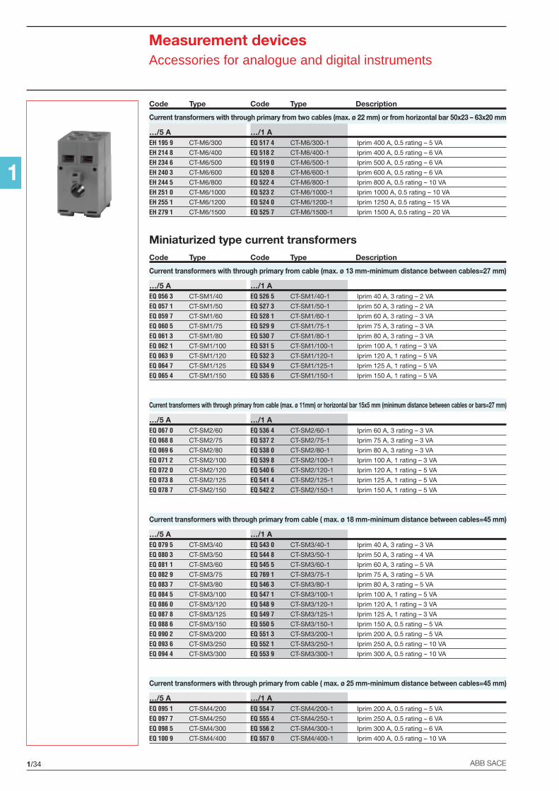
1/34 ABB SACE
1
Measurement devicesAccessories for analogue and digital instruments
Code Type Code Type Description
Current transformers with through primary from two cables (max. ø 22 mm) or from horizontal bar 50x23 – 63x20 mm
…/5 A …/1 AEH 195 9 CT-M6/300 EQ 517 4 CT-M6/300-1 Iprim 400 A, 0.5 rating – 5 VA
EH 214 8 CT-M6/400 EQ 518 2 CT-M6/400-1 Iprim 400 A, 0.5 rating – 6 VA
EH 234 6 CT-M6/500 EQ 519 0 CT-M6/500-1 Iprim 500 A, 0.5 rating – 6 VA
EH 240 3 CT-M6/600 EQ 520 8 CT-M6/600-1 Iprim 600 A, 0.5 rating – 6 VA
EH 244 5 CT-M6/800 EQ 522 4 CT-M6/800-1 Iprim 800 A, 0.5 rating – 10 VA
EH 251 0 CT-M6/1000 EQ 523 2 CT-M6/1000-1 Iprim 1000 A, 0.5 rating – 10 VA
EH 255 1 CT-M6/1200 EQ 524 0 CT-M6/1200-1 Iprim 1250 A, 0.5 rating – 15 VA
EH 279 1 CT-M6/1500 EQ 525 7 CT-M6/1500-1 Iprim 1500 A, 0.5 rating – 20 VA
Miniaturized type current transformersCode Type Code Type Description
Current transformers with through primary from cable (max. ø 13 mm-minimum distance between cables=27 mm)
…/5 A …/1 AEQ 056 3 CT-SM1/40 EQ 526 5 CT-SM1/40-1 Iprim 40 A, 3 rating – 2 VA
EQ 057 1 CT-SM1/50 EQ 527 3 CT-SM1/50-1 Iprim 50 A, 3 rating – 2 VA
EQ 059 7 CT-SM1/60 EQ 528 1 CT-SM1/60-1 Iprim 60 A, 3 rating – 3 VA
EQ 060 5 CT-SM1/75 EQ 529 9 CT-SM1/75-1 Iprim 75 A, 3 rating – 3 VA
EQ 061 3 CT-SM1/80 EQ 530 7 CT-SM1/80-1 Iprim 80 A, 3 rating – 3 VA
EQ 062 1 CT-SM1/100 EQ 531 5 CT-SM1/100-1 Iprim 100 A, 1 rating – 3 VA
EQ 063 9 CT-SM1/120 EQ 532 3 CT-SM1/120-1 Iprim 120 A, 1 rating – 5 VA
EQ 064 7 CT-SM1/125 EQ 534 9 CT-SM1/125-1 Iprim 125 A, 1 rating – 5 VA
EQ 065 4 CT-SM1/150 EQ 535 6 CT-SM1/150-1 Iprim 150 A, 1 rating – 5 VA
Current transformers with through primary from cable (max. ø 11mm) or horizontal bar 15x5 mm (minimum distance between cables or bars=27 mm)
…/5 A …/1 AEQ 067 0 CT-SM2/60 EQ 536 4 CT-SM2/60-1 Iprim 60 A, 3 rating – 3 VA
EQ 068 8 CT-SM2/75 EQ 537 2 CT-SM2/75-1 Iprim 75 A, 3 rating – 3 VA
EQ 069 6 CT-SM2/80 EQ 538 0 CT-SM2/80-1 Iprim 80 A, 3 rating – 3 VA
EQ 071 2 CT-SM2/100 EQ 539 8 CT-SM2/100-1 Iprim 100 A, 1 rating – 3 VA
EQ 072 0 CT-SM2/120 EQ 540 6 CT-SM2/120-1 Iprim 120 A, 1 rating – 5 VA
EQ 073 8 CT-SM2/125 EQ 541 4 CT-SM2/125-1 Iprim 125 A, 1 rating – 5 VA
EQ 078 7 CT-SM2/150 EQ 542 2 CT-SM2/150-1 Iprim 150 A, 1 rating – 5 VA
Current transformers with through primary from cable ( max. ø 18 mm-minimum distance between cables=45 mm)
…/5 A …/1 AEQ 079 5 CT-SM3/40 EQ 543 0 CT-SM3/40-1 Iprim 40 A, 3 rating – 3 VA
EQ 080 3 CT-SM3/50 EQ 544 8 CT-SM3/50-1 Iprim 50 A, 3 rating – 4 VA
EQ 081 1 CT-SM3/60 EQ 545 5 CT-SM3/60-1 Iprim 60 A, 3 rating – 5 VA
EQ 082 9 CT-SM3/75 EQ 769 1 CT-SM3/75-1 Iprim 75 A, 3 rating – 5 VA
EQ 083 7 CT-SM3/80 EQ 546 3 CT-SM3/80-1 Iprim 80 A, 3 rating – 5 VA
EQ 084 5 CT-SM3/100 EQ 547 1 CT-SM3/100-1 Iprim 100 A, 1 rating – 5 VA
EQ 086 0 CT-SM3/120 EQ 548 9 CT-SM3/120-1 Iprim 120 A, 1 rating – 3 VA
EQ 087 8 CT-SM3/125 EQ 549 7 CT-SM3/125-1 Iprim 125 A, 1 rating – 3 VA
EQ 088 6 CT-SM3/150 EQ 550 5 CT-SM3/150-1 Iprim 150 A, 0.5 rating – 5 VA
EQ 090 2 CT-SM3/200 EQ 551 3 CT-SM3/200-1 Iprim 200 A, 0.5 rating – 5 VA
EQ 093 6 CT-SM3/250 EQ 552 1 CT-SM3/250-1 Iprim 250 A, 0.5 rating – 10 VA
EQ 094 4 CT-SM3/300 EQ 553 9 CT-SM3/300-1 Iprim 300 A, 0.5 rating – 10 VA
Current transformers with through primary from cable ( max. ø 25 mm-minimum distance between cables=45 mm)
…/5 A …/1 AEQ 095 1 CT-SM4/200 EQ 554 7 CT-SM4/200-1 Iprim 200 A, 0.5 rating – 5 VA
EQ 097 7 CT-SM4/250 EQ 555 4 CT-SM4/250-1 Iprim 250 A, 0.5 rating – 6 VA
EQ 098 5 CT-SM4/300 EQ 556 2 CT-SM4/300-1 Iprim 300 A, 0.5 rating – 6 VA
EQ 100 9 CT-SM4/400 EQ 557 0 CT-SM4/400-1 Iprim 400 A, 0.5 rating – 10 VA
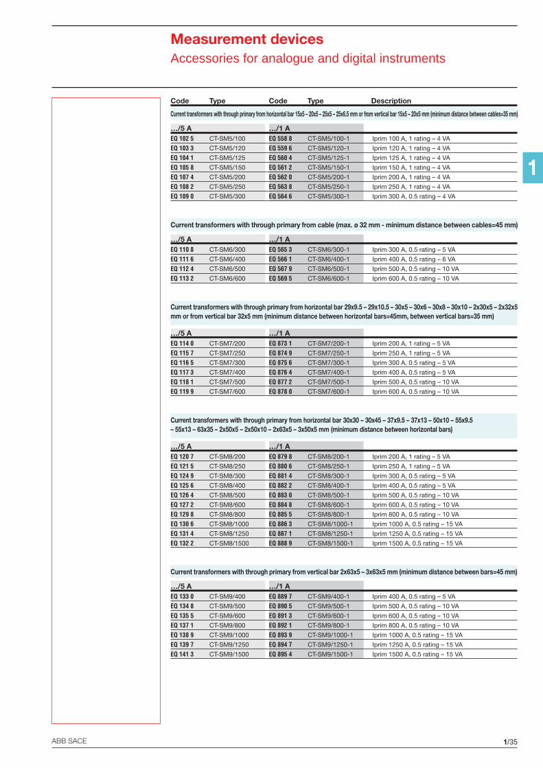
1/35ABB SACE
1
Measurement devicesAccessories for analogue and digital instruments
Code Type Code Type Description
Current transformers with through primary from horizontal bar 15x5 – 20x5 – 25x5 – 25x6.5 mm or from vertical bar 15x5 – 20x5 mm (minimum distance between cables=35 mm)
…/5 A …/1 AEQ 102 5 CT-SM5/100 EQ 558 8 CT-SM5/100-1 Iprim 100 A, 1 rating – 4 VA
EQ 103 3 CT-SM5/120 EQ 559 6 CT-SM5/120-1 Iprim 120 A, 1 rating – 4 VA
EQ 104 1 CT-SM5/125 EQ 560 4 CT-SM5/125-1 Iprim 125 A, 1 rating – 4 VA
EQ 105 8 CT-SM5/150 EQ 561 2 CT-SM5/150-1 Iprim 150 A, 1 rating – 4 VA
EQ 107 4 CT-SM5/200 EQ 562 0 CT-SM5/200-1 Iprim 200 A, 1 rating – 4 VA
EQ 108 2 CT-SM5/250 EQ 563 8 CT-SM5/250-1 Iprim 250 A, 1 rating – 4 VA
EQ 109 0 CT-SM5/300 EQ 564 6 CT-SM5/300-1 Iprim 300 A, 0.5 rating – 4 VA
Current transformers with through primary from cable (max. ø 32 mm - minimum distance between cables=45 mm)
…/5 A …/1 AEQ 110 8 CT-SM6/300 EQ 565 3 CT-SM6/300-1 Iprim 300 A, 0.5 rating – 5 VA
EQ 111 6 CT-SM6/400 EQ 566 1 CT-SM6/400-1 Iprim 400 A, 0.5 rating – 6 VA
EQ 112 4 CT-SM6/500 EQ 567 9 CT-SM6/500-1 Iprim 500 A, 0.5 rating – 10 VA
EQ 113 2 CT-SM6/600 EQ 569 5 CT-SM6/600-1 Iprim 600 A, 0.5 rating – 10 VA
Current transformers with through primary from horizontal bar 29x9.5 – 29x10.5 – 30x5 – 30x6 – 30x8 – 30x10 – 2x30x5 – 2x32x5mm or from vertical bar 32x5 mm (minimum distance between horizontal bars=45mm, between vertical bars=35 mm)
…/5 A …/1 AEQ 114 0 CT-SM7/200 EQ 873 1 CT-SM7/200-1 Iprim 200 A, 1 rating – 5 VA
EQ 115 7 CT-SM7/250 EQ 874 9 CT-SM7/250-1 Iprim 250 A, 1 rating – 5 VA
EQ 116 5 CT-SM7/300 EQ 875 6 CT-SM7/300-1 Iprim 300 A, 0.5 rating – 5 VA
EQ 117 3 CT-SM7/400 EQ 876 4 CT-SM7/400-1 Iprim 400 A, 0.5 rating – 5 VA
EQ 118 1 CT-SM7/500 EQ 877 2 CT-SM7/500-1 Iprim 500 A, 0.5 rating – 10 VA
EQ 119 9 CT-SM7/600 EQ 878 0 CT-SM7/600-1 Iprim 600 A, 0.5 rating – 10 VA
Current transformers with through primary from horizontal bar 30x30 – 30x45 – 37x9.5 – 37x13 – 50x10 – 55x9.5– 55x13 – 63x35 – 2x50x5 – 2x50x10 – 2x63x5 – 3x50x5 mm (minimum distance between horizontal bars)
…/5 A …/1 AEQ 120 7 CT-SM8/200 EQ 879 8 CT-SM8/200-1 Iprim 200 A, 1 rating – 5 VA
EQ 121 5 CT-SM8/250 EQ 880 6 CT-SM8/250-1 Iprim 250 A, 1 rating – 5 VA
EQ 124 9 CT-SM8/300 EQ 881 4 CT-SM8/300-1 Iprim 300 A, 0.5 rating – 5 VA
EQ 125 6 CT-SM8/400 EQ 882 2 CT-SM8/400-1 Iprim 400 A, 0.5 rating – 5 VA
EQ 126 4 CT-SM8/500 EQ 883 0 CT-SM8/500-1 Iprim 500 A, 0.5 rating – 10 VA
EQ 127 2 CT-SM8/600 EQ 884 8 CT-SM8/600-1 Iprim 600 A, 0.5 rating – 10 VA
EQ 129 8 CT-SM8/800 EQ 885 5 CT-SM8/800-1 Iprim 800 A, 0.5 rating – 10 VA
EQ 130 6 CT-SM8/1000 EQ 886 3 CT-SM8/1000-1 Iprim 1000 A, 0.5 rating – 15 VA
EQ 131 4 CT-SM8/1250 EQ 887 1 CT-SM8/1250-1 Iprim 1250 A, 0.5 rating – 15 VA
EQ 132 2 CT-SM8/1500 EQ 888 9 CT-SM8/1500-1 Iprim 1500 A, 0.5 rating – 15 VA
Current transformers with through primary from vertical bar 2x63x5 – 3x63x5 mm (minimum distance between bars=45 mm)
…/5 A …/1 AEQ 133 0 CT-SM9/400 EQ 889 7 CT-SM9/400-1 Iprim 400 A, 0.5 rating – 5 VA
EQ 134 8 CT-SM9/500 EQ 890 5 CT-SM9/500-1 Iprim 500 A, 0.5 rating – 10 VA
EQ 135 5 CT-SM9/600 EQ 891 3 CT-SM9/600-1 Iprim 600 A, 0.5 rating – 10 VA
EQ 137 1 CT-SM9/800 EQ 892 1 CT-SM9/800-1 Iprim 800 A, 0.5 rating – 10 VA
EQ 138 9 CT-SM9/1000 EQ 893 9 CT-SM9/1000-1 Iprim 1000 A, 0.5 rating – 15 VA
EQ 139 7 CT-SM9/1250 EQ 894 7 CT-SM9/1250-1 Iprim 1250 A, 0.5 rating – 15 VA
EQ 141 3 CT-SM9/1500 EQ 895 4 CT-SM9/1500-1 Iprim 1500 A, 0.5 rating – 15 VA
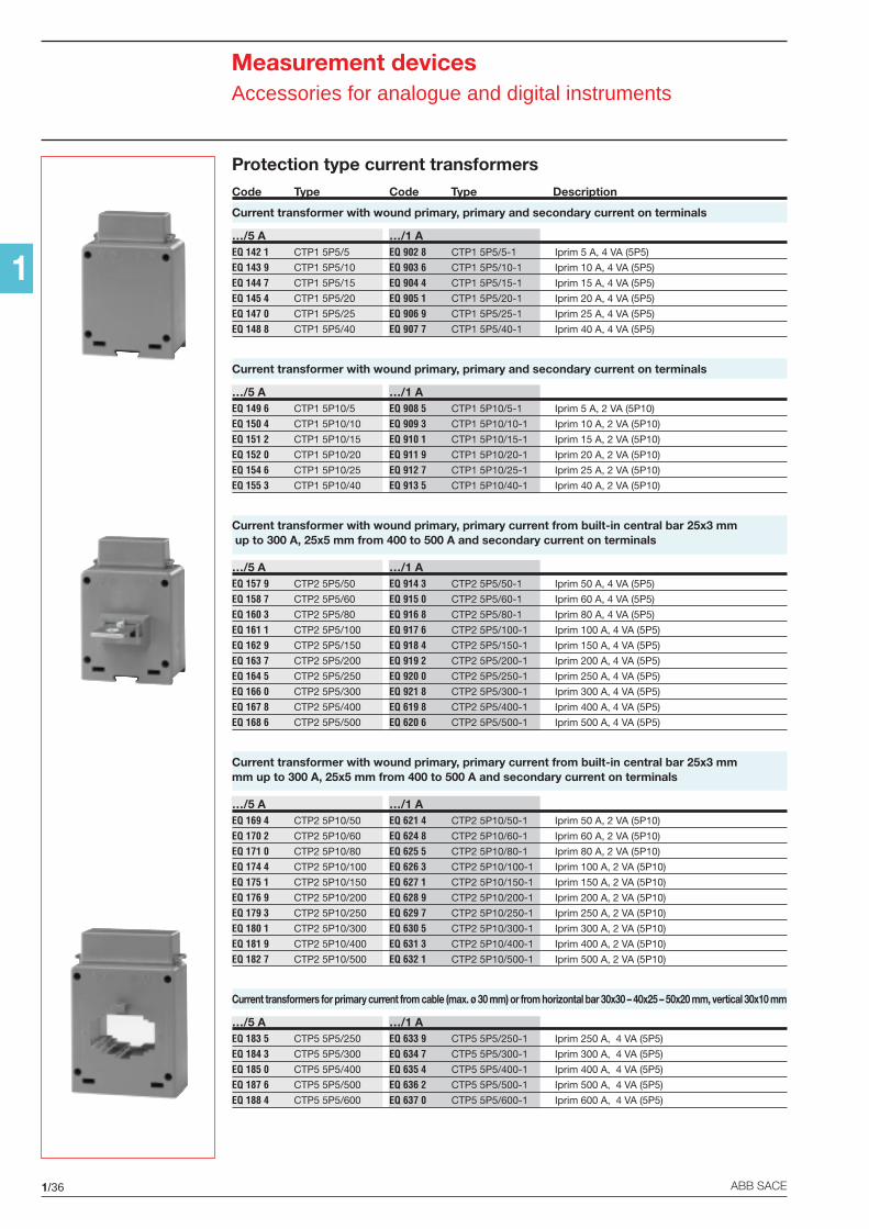
1/36 ABB SACE
1
Measurement devicesAccessories for analogue and digital instruments
Protection type current transformersCode Type Code Type Description
Current transformer with wound primary, primary and secondary current on terminals
…/5 A …/1 AEQ 142 1 CTP1 5P5/5 EQ 902 8 CTP1 5P5/5-1 Iprim 5 A, 4 VA (5P5)
EQ 143 9 CTP1 5P5/10 EQ 903 6 CTP1 5P5/10-1 Iprim 10 A, 4 VA (5P5)
EQ 144 7 CTP1 5P5/15 EQ 904 4 CTP1 5P5/15-1 Iprim 15 A, 4 VA (5P5)
EQ 145 4 CTP1 5P5/20 EQ 905 1 CTP1 5P5/20-1 Iprim 20 A, 4 VA (5P5)
EQ 147 0 CTP1 5P5/25 EQ 906 9 CTP1 5P5/25-1 Iprim 25 A, 4 VA (5P5)
EQ 148 8 CTP1 5P5/40 EQ 907 7 CTP1 5P5/40-1 Iprim 40 A, 4 VA (5P5)
Current transformer with wound primary, primary and secondary current on terminals
…/5 A …/1 AEQ 149 6 CTP1 5P10/5 EQ 908 5 CTP1 5P10/5-1 Iprim 5 A, 2 VA (5P10)
EQ 150 4 CTP1 5P10/10 EQ 909 3 CTP1 5P10/10-1 Iprim 10 A, 2 VA (5P10)
EQ 151 2 CTP1 5P10/15 EQ 910 1 CTP1 5P10/15-1 Iprim 15 A, 2 VA (5P10)
EQ 152 0 CTP1 5P10/20 EQ 911 9 CTP1 5P10/20-1 Iprim 20 A, 2 VA (5P10)
EQ 154 6 CTP1 5P10/25 EQ 912 7 CTP1 5P10/25-1 Iprim 25 A, 2 VA (5P10)
EQ 155 3 CTP1 5P10/40 EQ 913 5 CTP1 5P10/40-1 Iprim 40 A, 2 VA (5P10)
Current transformer with wound primary, primary current from built-in central bar 25x3 mm up to 300 A, 25x5 mm from 400 to 500 A and secondary current on terminals
…/5 A …/1 AEQ 157 9 CTP2 5P5/50 EQ 914 3 CTP2 5P5/50-1 Iprim 50 A, 4 VA (5P5)
EQ 158 7 CTP2 5P5/60 EQ 915 0 CTP2 5P5/60-1 Iprim 60 A, 4 VA (5P5)
EQ 160 3 CTP2 5P5/80 EQ 916 8 CTP2 5P5/80-1 Iprim 80 A, 4 VA (5P5)
EQ 161 1 CTP2 5P5/100 EQ 917 6 CTP2 5P5/100-1 Iprim 100 A, 4 VA (5P5)
EQ 162 9 CTP2 5P5/150 EQ 918 4 CTP2 5P5/150-1 Iprim 150 A, 4 VA (5P5)
EQ 163 7 CTP2 5P5/200 EQ 919 2 CTP2 5P5/200-1 Iprim 200 A, 4 VA (5P5)
EQ 164 5 CTP2 5P5/250 EQ 920 0 CTP2 5P5/250-1 Iprim 250 A, 4 VA (5P5)
EQ 166 0 CTP2 5P5/300 EQ 921 8 CTP2 5P5/300-1 Iprim 300 A, 4 VA (5P5)
EQ 167 8 CTP2 5P5/400 EQ 619 8 CTP2 5P5/400-1 Iprim 400 A, 4 VA (5P5)
EQ 168 6 CTP2 5P5/500 EQ 620 6 CTP2 5P5/500-1 Iprim 500 A, 4 VA (5P5)
Current transformer with wound primary, primary current from built-in central bar 25x3 mmmm up to 300 A, 25x5 mm from 400 to 500 A and secondary current on terminals
…/5 A …/1 AEQ 169 4 CTP2 5P10/50 EQ 621 4 CTP2 5P10/50-1 Iprim 50 A, 2 VA (5P10)
EQ 170 2 CTP2 5P10/60 EQ 624 8 CTP2 5P10/60-1 Iprim 60 A, 2 VA (5P10)
EQ 171 0 CTP2 5P10/80 EQ 625 5 CTP2 5P10/80-1 Iprim 80 A, 2 VA (5P10)
EQ 174 4 CTP2 5P10/100 EQ 626 3 CTP2 5P10/100-1 Iprim 100 A, 2 VA (5P10)
EQ 175 1 CTP2 5P10/150 EQ 627 1 CTP2 5P10/150-1 Iprim 150 A, 2 VA (5P10)
EQ 176 9 CTP2 5P10/200 EQ 628 9 CTP2 5P10/200-1 Iprim 200 A, 2 VA (5P10)
EQ 179 3 CTP2 5P10/250 EQ 629 7 CTP2 5P10/250-1 Iprim 250 A, 2 VA (5P10)
EQ 180 1 CTP2 5P10/300 EQ 630 5 CTP2 5P10/300-1 Iprim 300 A, 2 VA (5P10)
EQ 181 9 CTP2 5P10/400 EQ 631 3 CTP2 5P10/400-1 Iprim 400 A, 2 VA (5P10)
EQ 182 7 CTP2 5P10/500 EQ 632 1 CTP2 5P10/500-1 Iprim 500 A, 2 VA (5P10)
Current transformers for primary current from cable (max. ø 30 mm) or from horizontal bar 30x30 – 40x25 – 50x20 mm, vertical 30x10 mm
…/5 A …/1 AEQ 183 5 CTP5 5P5/250 EQ 633 9 CTP5 5P5/250-1 Iprim 250 A, 4 VA (5P5)
EQ 184 3 CTP5 5P5/300 EQ 634 7 CTP5 5P5/300-1 Iprim 300 A, 4 VA (5P5)
EQ 185 0 CTP5 5P5/400 EQ 635 4 CTP5 5P5/400-1 Iprim 400 A, 4 VA (5P5)
EQ 187 6 CTP5 5P5/500 EQ 636 2 CTP5 5P5/500-1 Iprim 500 A, 4 VA (5P5)
EQ 188 4 CTP5 5P5/600 EQ 637 0 CTP5 5P5/600-1 Iprim 600 A, 4 VA (5P5)

1/37ABB SACE
1
Measurement devicesAccessories for analogue and digital instruments
Code Type Code Type Description…/5 A …/1 AEQ 189 2 CTP5 5P5/800 EQ 638 8 CTP5 5P5/800-1 Iprim 800 A, 4 VA (5P5)
EQ 191 8 CTP5 5P5/1000 EQ 639 6 CTP5 5P5/1000-1 Iprim 1000 A, 4 VA (5P5)
EQ 192 6 CTP5 5P5/1200 EQ 640 4 CTP5 5P5/1200-1 Iprim 1200 A, 6 VA (5P5)
EQ 193 4 CTP5 5P5/1500 EQ 641 2 CTP5 5P5/1500-1 Iprim 1500 A, 8 VA (5P5)
Current transformers for primary current from cable (max. ø 30 mm) or from horizontal bar 30x30 – 40x25 – 50x20 mm, vertical 30x10 mm
…/5 A …/1 AEQ 194 2 CTP5 5P10/250 EQ 642 0 CTP5 5P10/250-1 Iprim 250 A, 2 VA (5P10)
EQ 195 9 CTP5 5P10/300 EQ 643 8 CTP5 5P10/300-1 Iprim 300 A, 2 VA (5P10)
EQ 198 3 CTP5 5P10/400 EQ 644 6 CTP5 5P10/400-1 Iprim 400 A, 2 VA (5P10)
EQ 199 1 CTP5 5P10/500 EQ 645 3 CTP5 5P10/500-1 Iprim 500 A, 2 VA (5P10)
EQ 200 7 CTP5 5P10/600 EQ 646 1 CTP5 5P10/600-1 Iprim 600 A, 2 VA (5P10)
EQ 201 5 CTP5 5P10/800 EQ 647 9 CTP5 5P10/800-1 Iprim 800 A, 2 VA (5P10)
EQ 202 3 CTP5 5P10/1000 EQ 648 7 CTP5 5P10/1000-1 Iprim 1000 A, 2 VA (5P10)
EQ 203 1 CTP5 5P10/1200 EQ 649 5 CTP5 5P10/1200-1 Iprim 1200 A, 3 VA (5P10)
EQ 204 9 CTP5 5P10/1500 EQ 650 3 CTP5 5P10/1500-1 Iprim 1500 A, 4 VA (5P10)
Current transformers for primary current from cable (max. ø 50 mm) or from horizontal bar 50x20 – 60x20 mm
…/5 A …/1 AEQ 206 4 CTP6 5P5/250 EQ 651 1 CTP6 5P5/250-1 Iprim 250 A, 6 VA (5P5)
EQ 207 2 CTP6 5P5/300 EQ 652 9 CTP6 5P5/300-1 Iprim 300 A, 6 VA (5P5)
EQ 208 0 CTP6 5P5/400 EQ 653 7 CTP6 5P5/400-1 Iprim 400 A, 10 VA (5P5)
EQ 210 6 CTP6 5P5/500 EQ 654 5 CTP6 5P5/500-1 Iprim 500 A, 10 VA (5P5)
EQ 213 0 CTP6 5P5/600 EQ 655 2 CTP6 5P5/600-1 Iprim 600 A, 10 VA (5P5)
EQ 214 8 CTP6 5P5/800 EQ 656 0 CTP6 5P5/800-1 Iprim 800 A, 15 VA (5P5)
EQ 215 5 CTP6 5P5/1000 EQ 657 8 CTP6 5P5/1000-1 Iprim 1000 A, 20 VA (5P5)
EQ 217 1 CTP6 5P5/1200 EQ 658 6 CTP6 5P5/1200-1 Iprim 1200 A, 20 VA (5P5)
EQ 218 9 CTP6 5P5/1500 EQ 659 4 CTP6 5P5/1500-1 Iprim 1500 A, 30 VA (5P5)
Current transformers for primary current from cable (max. ø 50 mm) or from horizontal bar 50x20 – 60x20 mm
…/5 A …/1 AEQ 220 5 CTP6 5P10/250 EQ 661 0 CTP6 5P10/250-1 Iprim 250 A, 2 VA (5P10)
EQ 222 1 CTP6 5P10/300 EQ 662 8 CTP6 5P10/300-1 Iprim 300 A, 3 VA (5P10)
EQ 223 9 CTP6 5P10/400 EQ 663 6 CTP6 5P10/400-1 Iprim 400 A, 4 VA (5P10)
EQ 224 7 CTP6 5P10/500 EQ 664 4 CTP6 5P10/500-1 Iprim 500 A, 4 VA (5P10)
EQ 225 4 CTP6 5P10/600 EQ 665 1 CTP6 5P10/600-1 Iprim 600 A, 4 VA (5P10)
EQ 227 0 CTP6 5P10/800 EQ 666 9 CTP6 5P10/800-1 Iprim 800 A, 5 VA (5P10)
EQ 228 8 CTP6 5P10/1000 EQ 667 7 CTP6 5P10/1000-1 Iprim 1000 A, 6 VA (5P10)
EQ 229 6 CTP6 5P10/1200 EQ 668 5 CTP6 5P10/1200-1 Iprim 1200 A, 6 VA (5P10)
EQ 230 4 CTP6 5P10/1500 EQ 669 3 CTP6 5P10/1500-1 Iprim 1500 A, 10 VA (5P10)
Current transformers for primary current from two cables (max. ø 30 mm each) or from horizontal bar 60x30 – 80x30 mm
…/5 A …/1 AEQ 231 2 CTP8 5P5/300 EQ 670 1 CTP8 5P5/300-1 Iprim 300 A, 5 VA (5P5)
EQ 234 6 CTP8 5P5/400 EQ 671 9 CTP8 5P5/400-1 Iprim 400 A, 6 VA (5P5)
EQ 235 3 CTP8 5P5/500 EQ 672 7 CTP8 5P5/500-1 Iprim 500 A, 15 VA (5P5)
EQ 236 1 CTP8 5P5/600 EQ 673 5 CTP8 5P5/600-1 Iprim 600 A, 20 VA (5P5)
EQ 237 9 CTP8 5P5/800 EQ 674 3 CTP8 5P5/800-1 Iprim 800 A, 20 VA (5P5)
EQ 239 5 CTP8 5P5/1000 EQ 675 0 CTP8 5P5/1000-1 Iprim 1000 A, 20 VA (5P5)
EQ 240 3 CTP8 5P5/1200 EQ 676 8 CTP8 5P5/1200-1 Iprim 1200 A, 30 VA (5P5)
EQ 241 1 CTP8 5P5/1500 EQ 677 6 CTP8 5P5/1500-1 Iprim 1500 A, 20 VA (5P5)
EQ 242 9 CTP8 5P5/2000 EQ 678 4 CTP8 5P5/2000-1 Iprim 2000 A, 12 VA (5P5)
EQ 243 7 CTP8 5P5/2500 EQ 679 2 CTP8 5P5/2500-1 Iprim 2500 A, 15 VA (5P5)
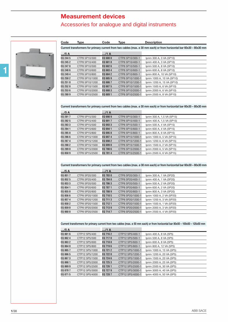
1/38 ABB SACE
1
Measurement devicesAccessories for analogue and digital instruments
Code Type Code Type Description
Current transformers for primary current from two cables (max. ø 30 mm each) or from horizontal bar 60x30 – 80x30 mm
…/5 A …/1 AEQ 244 5 CTP8 5P10/300 EQ 680 0 CTP8 5P10/300-1 Iprim 300 A, 3 VA (5P10)
EQ 245 2 CTP8 5P10/400 EQ 681 8 CTP8 5P10/400-1 Iprim 400 A, 3 VA (5P10)
EQ 247 8 CTP8 5P10/500 EQ 682 6 CTP8 5P10/500-1 Iprim 500 A, 8 VA (5P10)
EQ 248 6 CTP8 5P10/600 EQ 683 4 CTP8 5P10/600-1 Iprim 600 A, 8 VA (5P10)
EQ 249 4 CTP8 5P10/800 EQ 684 2 CTP8 5P10/800-1 Iprim 800 A, 10 VA (5P10)
EQ 250 2 CTP8 5P10/1000 EQ 685 9 CTP8 5P10/1000-1 Iprim 1000 A, 10 VA (5P10)
EQ 251 0 CTP8 5P10/1200 EQ 686 7 CTP8 5P10/1200-1 Iprim 1200 A, 15 VA (5P10)
EQ 252 8 CTP8 5P10/1500 EQ 687 5 CTP8 5P10/1500-1 Iprim 1500 A, 6 VA (5P10)
EQ 253 6 CTP8 5P10/2000 EQ 688 3 CTP8 5P10/2000-1 Iprim 2000 A, 6 VA (5P10)
EQ 280 9 CTP8 5P10/2500 EQ 689 1 CTP8 5P10/2500-1 Iprim 2500 A, 8 VA (5P10)
Current transformers for primary current from two cables (max. ø 30 mm each) or from horizontal bar 60x30 – 80x30 mm
…/5 A …/1 AEQ 281 7 CTP8 5P15/300 EQ 690 9 CTP8 5P15/300-1 Iprim 300 A, 1,5 VA (5P15)
EQ 282 5 CTP8 5P15/400 EQ 691 7 CTP8 5P15/400-1 Iprim 400 A, 1,5 VA (5P15)
EQ 283 3 CTP8 5P15/500 EQ 693 3 CTP8 5P15/500-1 Iprim 500 A, 4 VA (5P15)
EQ 284 1 CTP8 5P15/600 EQ 694 1 CTP8 5P15/600-1 Iprim 600 A, 4 VA (5P15)
EQ 285 8 CTP8 5P15/800 EQ 695 8 CTP8 5P15/800-1 Iprim 800 A, 6 VA (5P15)
EQ 286 6 CTP8 5P15/1000 EQ 697 4 CTP8 5P15/1000-1 Iprim 1000 A, 5 VA (5P15)
EQ 287 4 CTP8 5P15/1200 EQ 698 2 CTP8 5P15/1200-1 Iprim 1200 A, 6 VA (5P15)
EQ 288 2 CTP8 5P15/1500 EQ 699 0 CTP8 5P15/1500-1 Iprim 1500 A, 2 VA (5P15)
EQ 289 0 CTP8 5P15/2000 EQ 700 6 CTP8 5P15/2000-1 Iprim 2000 A, 5 VA (5P15)
EQ 850 9 CTP8 5P15/2500 EQ 701 4 CTP8 5P15/2500-1 Iprim 2500 A, 6 VA (5P15)
Current transformers for primary current from two cables (max. ø 30 mm each) or from horizontal bar 60x30 – 80x30 mm
…/5 A …/1 AEQ 851 7 CTP8 5P20/300 EQ 703 0 CTP8 5P20/300-1 Iprim 300 A, 1 VA (5P20)
EQ 852 5 CTP8 5P20/400 EQ 704 8 CTP8 5P20/400-1 Iprim 400 A, 1 VA (5P20)
EQ 853 3 CTP8 5P20/500 EQ 706 3 CTP8 5P20/500-1 Iprim 500 A, 2 VA (5P20)
EQ 854 1 CTP8 5P20/600 EQ 707 1 CTP8 5P20/600-1 Iprim 600 A, 2 VA (5P20)
EQ 855 8 CTP8 5P20/800 EQ 708 9 CTP8 5P20/800-1 Iprim 800 A, 3 VA (5P20)
EQ 856 6 CTP8 5P20/1000 EQ 710 5 CTP8 5P20/1000-1 Iprim 1000 A, 2 VA (5P20)
EQ 857 4 CTP8 5P20/1200 EQ 711 3 CTP8 5P20/1200-1 Iprim 1200 A, 3 VA (5P20)
EQ 858 2 CTP8 5P20/1500 EQ 712 1 CTP8 5P20/1500-1 Iprim 1500 A, 1 VA (5P20)
EQ 859 0 CTP8 5P20/2000 EQ 713 9 CTP8 5P20/2000-1 Iprim 2000 A, 3 VA (5P20)
EQ 860 8 CTP8 5P20/2500 EQ 714 7 CTP8 5P20/2500-1 Iprim 2500 A, 4 VA (5P20)
Current transformers for primary current from two cables (max. ø 50 mm each) or from horizontal bar 80x50 – 100x50 – 125x50 mm
…/5 A …/1 AEQ 861 6 CTP12 5P5/400 EQ 716 2 CTP12 5P5/400-1 Iprim 400 A, 8 VA (5P5)
EQ 862 4 CTP12 5P5/500 EQ 717 0 CTP12 5P5/500-1 Iprim 500 A, 8 VA (5P5)
EQ 863 2 CTP12 5P5/600 EQ 718 8 CTP12 5P5/600-1 Iprim 600 A, 8 VA (5P5)
EQ 864 0 CTP12 5P5/800 EQ 719 6 CTP12 5P5/800-1 Iprim 800 A, 12 VA (5P5)
EQ 865 7 CTP12 5P5/1000 EQ 721 2 CTP12 5P5/1000-1 Iprim 1000 A, 15 VA (5P5)
EQ 866 5 CTP12 5P5/1200 EQ 722 0 CTP12 5P5/1200-1 Iprim 1200 A, 20 VA (5P5)
EQ 867 3 CTP12 5P5/1500 EQ 724 6 CTP12 5P5/1500-1 Iprim 1500 A, 20 VA (5P5)
EQ 868 1 CTP12 5P5/2000 EQ 725 3 CTP12 5P5/2000-1 Iprim 2000 A, 25 VA (5P5)
EQ 869 9 CTP12 5P5/2500 EQ 726 1 CTP12 5P5/2500-1 Iprim 2500 A, 30 VA (5P5)
EQ 870 7 CTP12 5P5/3000 EQ 727 9 CTP12 5P5/3000-1 Iprim 3000 A, 40 VA (5P5)
EQ 871 5 CTP12 5P5/4000 EQ 728 7 CTP12 5P5/4000-1 Iprim 4000 A, 50 VA (5P5)

1/39ABB SACE
1
Measurement devicesAccessories for analogue and digital instruments
Code Type Code Type Description
Current transformers for primary current from two cables (max. ø 50 mm each) or from horizontal bar 80x50 – 100x50 – 125x50 mm
…/5 A …/1 AEQ 872 3 CTP12 5P10/400 EQ 729 5 CTP12 5P10/400-1 Iprim 400 A, 4 VA (5P10)
EQ 313 8 CTP12 5P10/500 EQ 733 7 CTP12 5P10/500-1 Iprim 500 A, 4 VA (5P10)
EQ 314 6 CTP12 5P10/600 EQ 734 5 CTP12 5P10/600-1 Iprim 600 A, 4 VA (5P10)
EQ 315 3 CTP12 5P10/800 EQ 735 2 CTP12 5P10/800-1 Iprim 800 A, 6 VA (5P10)
EQ 316 1 CTP12 5P10/1000 EQ 736 0 CTP12 5P10/1000-1 Iprim 1000 A, 8 VA (5P10)
EQ 317 9 CTP12 5P10/1200 EQ 737 8 CTP12 5P10/1200-1 Iprim 1200 A, 10 VA (5P10)
EQ 318 7 CTP12 5P10/1500 EQ 738 6 CTP12 5P10/1500-1 Iprim 1500 A, 10 VA (5P10)
EQ 319 5 CTP12 5P10/2000 EQ 739 4 CTP12 5P10/2000-1 Iprim 2000 A, 12 VA (5P10)
EQ 320 3 CTP12 5P10/2500 EQ 740 2 CTP12 5P10/2500-1 Iprim 2500 A, 15 VA (5P10)
EQ 321 1 CTP12 5P10/3000 EQ 741 0 CTP12 5P10/3000-1 Iprim 3000 A, 20 VA (5P10)
EQ 322 9 CTP12 5P10/4000 EQ 742 8 CTP12 5P10/4000-1 Iprim 4000 A, 25 VA (5P10)
Current transformers for primary current from two cables (max. ø 50 mm each) or from horizontal bar 80x50 – 100x50 – 125x50 mm
…/5 A …/1 AEQ 323 7 CTP12 5P15/400 EQ 743 6 CTP12 5P15/400-1 Iprim 400 A, 3 VA (5P15)
EQ 324 5 CTP12 5P15/500 EQ 744 4 CTP12 5P15/500-1 Iprim 500 A, 3 VA (5P15)
EQ 325 2 CTP12 5P15/600 EQ 745 1 CTP12 5P15/600-1 Iprim 600 A, 3 VA (5P15)
EQ 326 0 CTP12 5P15/800 EQ 746 9 CTP12 5P15/800-1 Iprim 800 A, 4 VA (5P15)
EQ 327 8 CTP12 5P15/1000 EQ 747 7 CTP12 5P15/1000-1 Iprim 1000 A, 6 VA (5P15)
EQ 328 6 CTP12 5P15/1200 EQ 748 5 CTP12 5P15/1200-1 Iprim 1200 A, 6 VA (5P15)
EQ 329 4 CTP12 5P15/1500 EQ 749 3 CTP12 5P15/1500-1 Iprim 1500 A, 6 VA (5P15)
EQ 330 2 CTP12 5P15/2000 EQ 750 1 CTP12 5P15/2000-1 Iprim 2000 A, 8 VA (5P15)
EQ 331 0 CTP12 5P15/2500 EQ 751 9 CTP12 5P15/2500-1 Iprim 2500 A, 10 VA (5P15)
EQ 332 8 CTP12 5P15/3000 EQ 752 7 CTP12 5P15/3000-1 Iprim 3000 A, 15 VA (5P15)
EQ 333 6 CTP12 5P15/4000 EQ 753 5 CTP12 5P15/4000-1 Iprim 4000 A, 15 VA (5P15)
Current transformers for primary current from two cables (max. ø 50 mm each) or from horizontal bar 80x50 – 100x50 – 125x50 mm
…/5 A …/1 AEQ 334 4 CTP12 5P20/400 EQ 754 3 CTP12 5P20/400-1 Iprim 400 A, 2 VA (5P20)
EQ 335 1 CTP12 5P20/500 EQ 755 0 CTP12 5P20/500-1 Iprim 500 A, 2 VA (5P20)
EQ 336 9 CTP12 5P20/600 EQ 756 8 CTP12 5P20/600-1 Iprim 600 A, 2 VA (5P20)
EQ 337 7 CTP12 5P20/800 EQ 757 6 CTP12 5P20/800-1 Iprim 800 A, 3 VA (5P20)
EQ 338 5 CTP12 5P20/1000 EQ 758 4 CTP12 5P20/1000-1 Iprim 1000 A, 4 VA (5P20)
EQ 339 3 CTP12 5P20/1200 EQ 759 2 CTP12 5P20/1200-1 Iprim 1200 A, 5 VA (5P20)
EQ 340 1 CTP12 5P20/1500 EQ 760 0 CTP12 5P20/1500-1 Iprim 1500 A, 5 VA (5P20)
EQ 341 9 CTP12 5P20/2000 EQ 761 8 CTP12 5P20/2000-1 Iprim 2000 A, 6 VA (5P20)
EQ 343 5 CTP12 5P20/2500 EQ 764 2 CTP12 5P20/2500-1 Iprim 2500 A, 8 VA (5P20)
EQ 344 3 CTP12 5P20/3000 EQ 767 5 CTP12 5P20/3000-1 Iprim 3000 A, 10 VA (5P20)
EQ 345 0 CTP12 5P20/4000 EQ 768 3 CTP12 5P20/4000-1 Iprim 4000 A, 12 VA (5P20)

1/40 ABB SACE
1
Measurement devicesAccessories for analogue and digital instruments
2CS
C44
5093
F00
01
Summing current transformers
They are used for calculating the vector sum of currents of two or more lines of a single voltagesystem.Installation on DIN rail.The insulation reference voltage is 0.72 kV – 3kV.
Code Type Description
Summing current transformers…/5 AEH 894 7 CTS-5-5 summing current transformer 5+5=5 A,
6 VA (6 DIN modules)
EH 896 2 CTS-5-5-5 summing current transformer 5+5+5=5 A,6 VA (6 DIN modules)
EH 897 0 CTS-5-5-5-5 summing current transformer 5+5+5+5=5 A,6 VA (6 DIN modules)
Summing current transformers…/1 AEH 898 8 CTS-1-1 summing current transformer 1+1=1 A,
0.5 rating – 10 VA
EH 899 6 CTS-1-1-1 summing current transformer 1+1+1=1 A,0.5 rating – 10 VA
EH 900 2 CTS-1-1-1-1 summing current transformer 1+1+1+1=1 A,0.5 rating – 10 VA
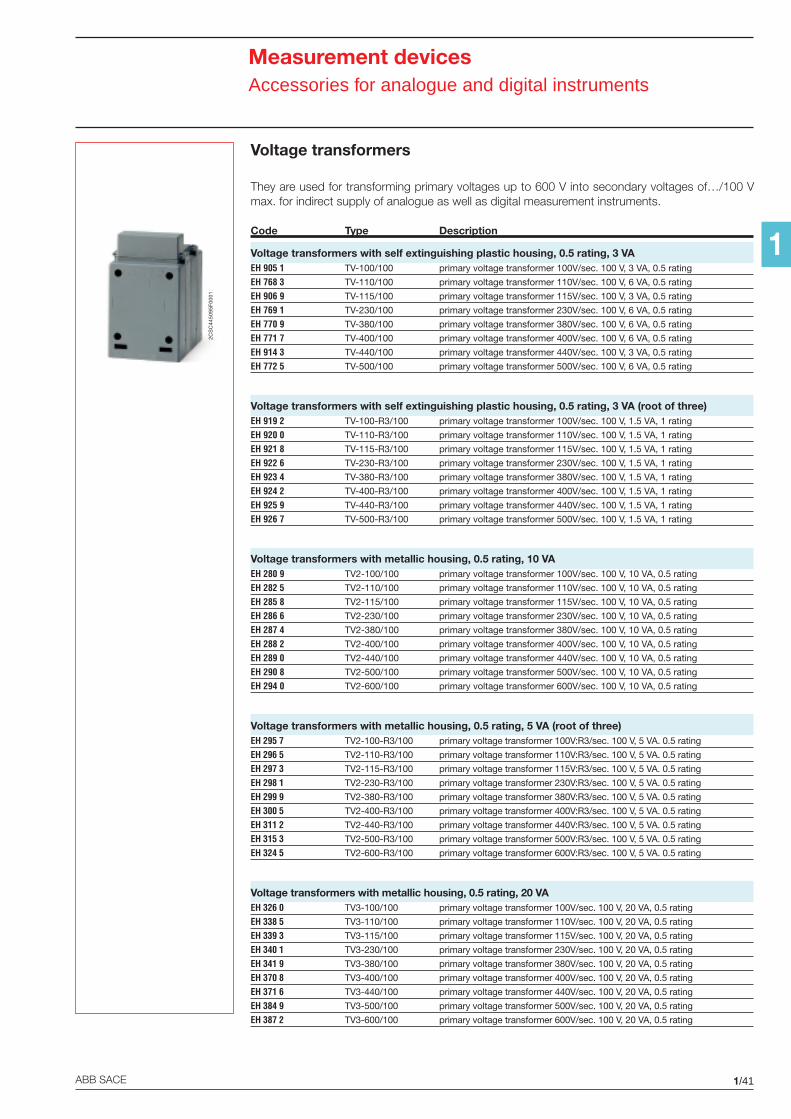
1/41ABB SACE
1
Measurement devicesAccessories for analogue and digital instruments
Voltage transformers
They are used for transforming primary voltages up to 600 V into secondary voltages of…/100 Vmax. for indirect supply of analogue as well as digital measurement instruments.
Code Type Description
Voltage transformers with self extinguishing plastic housing, 0.5 rating, 3 VAEH 905 1 TV-100/100 primary voltage transformer 100V/sec. 100 V, 3 VA, 0.5 rating
EH 768 3 TV-110/100 primary voltage transformer 110V/sec. 100 V, 6 VA, 0.5 rating
EH 906 9 TV-115/100 primary voltage transformer 115V/sec. 100 V, 3 VA, 0.5 rating
EH 769 1 TV-230/100 primary voltage transformer 230V/sec. 100 V, 6 VA, 0.5 rating
EH 770 9 TV-380/100 primary voltage transformer 380V/sec. 100 V, 6 VA, 0.5 rating
EH 771 7 TV-400/100 primary voltage transformer 400V/sec. 100 V, 6 VA, 0.5 rating
EH 914 3 TV-440/100 primary voltage transformer 440V/sec. 100 V, 3 VA, 0.5 rating
EH 772 5 TV-500/100 primary voltage transformer 500V/sec. 100 V, 6 VA, 0.5 rating
Voltage transformers with self extinguishing plastic housing, 0.5 rating, 3 VA (root of three)EH 919 2 TV-100-R3/100 primary voltage transformer 100V/sec. 100 V, 1.5 VA, 1 rating
EH 920 0 TV-110-R3/100 primary voltage transformer 110V/sec. 100 V, 1.5 VA, 1 rating
EH 921 8 TV-115-R3/100 primary voltage transformer 115V/sec. 100 V, 1.5 VA, 1 rating
EH 922 6 TV-230-R3/100 primary voltage transformer 230V/sec. 100 V, 1.5 VA, 1 rating
EH 923 4 TV-380-R3/100 primary voltage transformer 380V/sec. 100 V, 1.5 VA, 1 rating
EH 924 2 TV-400-R3/100 primary voltage transformer 400V/sec. 100 V, 1.5 VA, 1 rating
EH 925 9 TV-440-R3/100 primary voltage transformer 440V/sec. 100 V, 1.5 VA, 1 rating
EH 926 7 TV-500-R3/100 primary voltage transformer 500V/sec. 100 V, 1.5 VA, 1 rating
Voltage transformers with metallic housing, 0.5 rating, 10 VAEH 280 9 TV2-100/100 primary voltage transformer 100V/sec. 100 V, 10 VA, 0.5 rating
EH 282 5 TV2-110/100 primary voltage transformer 110V/sec. 100 V, 10 VA, 0.5 rating
EH 285 8 TV2-115/100 primary voltage transformer 115V/sec. 100 V, 10 VA, 0.5 rating
EH 286 6 TV2-230/100 primary voltage transformer 230V/sec. 100 V, 10 VA, 0.5 rating
EH 287 4 TV2-380/100 primary voltage transformer 380V/sec. 100 V, 10 VA, 0.5 rating
EH 288 2 TV2-400/100 primary voltage transformer 400V/sec. 100 V, 10 VA, 0.5 rating
EH 289 0 TV2-440/100 primary voltage transformer 440V/sec. 100 V, 10 VA, 0.5 rating
EH 290 8 TV2-500/100 primary voltage transformer 500V/sec. 100 V, 10 VA, 0.5 rating
EH 294 0 TV2-600/100 primary voltage transformer 600V/sec. 100 V, 10 VA, 0.5 rating
Voltage transformers with metallic housing, 0.5 rating, 5 VA (root of three)EH 295 7 TV2-100-R3/100 primary voltage transformer 100V:R3/sec. 100 V, 5 VA. 0.5 rating
EH 296 5 TV2-110-R3/100 primary voltage transformer 110V:R3/sec. 100 V, 5 VA. 0.5 rating
EH 297 3 TV2-115-R3/100 primary voltage transformer 115V:R3/sec. 100 V, 5 VA. 0.5 rating
EH 298 1 TV2-230-R3/100 primary voltage transformer 230V:R3/sec. 100 V, 5 VA. 0.5 rating
EH 299 9 TV2-380-R3/100 primary voltage transformer 380V:R3/sec. 100 V, 5 VA. 0.5 rating
EH 300 5 TV2-400-R3/100 primary voltage transformer 400V:R3/sec. 100 V, 5 VA. 0.5 rating
EH 311 2 TV2-440-R3/100 primary voltage transformer 440V:R3/sec. 100 V, 5 VA. 0.5 rating
EH 315 3 TV2-500-R3/100 primary voltage transformer 500V:R3/sec. 100 V, 5 VA. 0.5 rating
EH 324 5 TV2-600-R3/100 primary voltage transformer 600V:R3/sec. 100 V, 5 VA. 0.5 rating
Voltage transformers with metallic housing, 0.5 rating, 20 VAEH 326 0 TV3-100/100 primary voltage transformer 100V/sec. 100 V, 20 VA, 0.5 rating
EH 338 5 TV3-110/100 primary voltage transformer 110V/sec. 100 V, 20 VA, 0.5 rating
EH 339 3 TV3-115/100 primary voltage transformer 115V/sec. 100 V, 20 VA, 0.5 rating
EH 340 1 TV3-230/100 primary voltage transformer 230V/sec. 100 V, 20 VA, 0.5 rating
EH 341 9 TV3-380/100 primary voltage transformer 380V/sec. 100 V, 20 VA, 0.5 rating
EH 370 8 TV3-400/100 primary voltage transformer 400V/sec. 100 V, 20 VA, 0.5 rating
EH 371 6 TV3-440/100 primary voltage transformer 440V/sec. 100 V, 20 VA, 0.5 rating
EH 384 9 TV3-500/100 primary voltage transformer 500V/sec. 100 V, 20 VA, 0.5 rating
EH 387 2 TV3-600/100 primary voltage transformer 600V/sec. 100 V, 20 VA, 0.5 rating
2CS
C44
5095
F00
01
1/42 ABB SACE
1
Measurement devicesAccessories for analogue and digital instruments
Code Type Description
Voltage transformers with metallic housing, 0.5 rating, 10 VA (root of three)EH 388 0 TV3-100-R3/100 primary voltage transformer 100V:R3/sec. 100 V, 10 VA. 0.5 rating
EH 389 8 TV3-110-R3/100 primary voltage transformer 110V:R3/sec. 100 V, 10 VA. 0.5 rating
EH 390 6 TV3-115-R3/100 primary voltage transformer 115V:R3/sec. 100 V, 10 VA. 0.5 rating
EH 391 4 TV3-230-R3/100 primary voltage transformer 230V:R3/sec. 100 V, 10 VA. 0.5 rating
EH 402 9 TV3-380-R3/100 primary voltage transformer 380V:R3/sec. 100 V, 10 VA. 0.5 rating
EH 410 2 TV3-400-R3/100 primary voltage transformer 400V:R3/sec. 100 V, 10 VA. 0.5 rating
EH 412 8 TV3-440-R3/100 primary voltage transformer 440V:R3/sec. 100 V, 10 VA. 0.5 rating
EH 413 6 TV3-500-R3/100 primary voltage transformer 500V:R3/sec. 100 V, 10 VA. 0.5 rating
EH 414 4 TV3-600-R3/100 primary voltage transformer 600V:R3/sec. 100 V, 10 VA. 0.5 rating
Voltage transformers with metallic housing, 0.5 rating, 50 VAEH 415 1 TV4-100/100 primary voltage transformer 100V/sec. 100 V, 50 VA, 0.5 rating
EH 430 0 TV4-110/100 primary voltage transformer 110V/sec. 100 V, 50 VA, 0.5 rating
EH 432 6 TV4-115/100 primary voltage transformer 115V/sec. 100 V, 50 VA, 0.5 rating
EH 433 4 TV4-230/100 primary voltage transformer 230V/sec. 100 V, 50 VA, 0.5 rating
EH 455 7 TV4-380/100 primary voltage transformer 380V/sec. 100 V, 50 VA, 0.5 rating
EH 457 3 TV4-400/100 primary voltage transformer 400V/sec. 100 V, 50 VA, 0.5 rating
EH 458 1 TV4-440/100 primary voltage transformer 440V/sec. 100 V, 50 VA, 0.5 rating
EH 470 6 TV4-500/100 primary voltage transformer 500V/sec. 100 V, 50 VA, 0.5 rating
EH 473 0 TV4-600/100 primary voltage transformer 600V/sec. 100 V, 50 VA, 0.5 rating
Voltage transformers with metallic housing, 0.5 rating, 25 VA (root of three)EH 497 9 TV4-100-R3/100 primary voltage transformer 100V:R3/sec. 100 V, 25 VA. 0.5 rating
EH 498 7 TV4-110-R3/100 primary voltage transformer 110V:R3/sec. 100 V, 25 VA. 0.5 rating
EH 499 5 TV4-115-R3/100 primary voltage transformer 115V:R3/sec. 100 V, 25 VA. 0.5 rating
EH 500 0 TV4-230-R3/100 primary voltage transformer 230V:R3/sec. 100 V, 25 VA. 0.5 rating
EH 510 9 TV4-380-R3/100 primary voltage transformer 380V:R3/sec. 100 V, 25 VA. 0.5 rating
EH 522 4 TV4-400-R3/100 primary voltage transformer 400V:R3/sec. 100 V, 25 VA. 0.5 rating
EH 531 5 TV4-440-R3/100 primary voltage transformer 440V:R3/sec. 100 V, 25 VA. 0.5 rating
EH 550 5 TV4-500-R3/100 primary voltage transformer 500V:R3/sec. 100 V, 25 VA. 0.5 rating
EH 552 1 TV4-600-R3/100 primary voltage transformer 600V:R3/sec. 100 V, 25 VA. 0.5 rating
Voltage transformers with metallic housing, 0.5 rating, 100 VAEH 553 9 TV5-100/100 primary voltage transformer 100V/sec. 100 V, 100 VA, 0.5 rating
EH 554 7 TV5-110/100 primary voltage transformer 110V/sec. 100 V, 100 VA, 0.5 rating
EH 555 4 TV5-115/100 primary voltage transformer 115V/sec. 100 V, 100 VA, 0.5 rating
EH 558 8 TV5-230/100 primary voltage transformer 230V/sec. 100 V, 100 VA, 0.5 rating
EH 566 1 TV5-380/100 primary voltage transformer 380V/sec. 100 V, 100 VA, 0.5 rating
EH 567 9 TV5-400/100 primary voltage transformer 400V/sec. 100 V, 100 VA, 0.5 rating
EH 568 7 TV5-440/100 primary voltage transformer 440V/sec. 100 V, 100 VA, 0.5 rating
EH 569 5 TV5-500/100 primary voltage transformer 500V/sec. 100 V, 100 VA, 0.5 rating
EH 570 3 TV5-600/100 primary voltage transformer 600V/sec. 100 V, 100 VA, 0.5 rating
Voltage transformers with metallic housing, 0.5 rating, 50 VA (root of three)EH 571 1 TV5-100-R3/100 primary voltage transformer 100V:R3/sec. 100 V, 50 VA. 0.5 rating
EH 572 9 TV5-110-R3/100 primary voltage transformer 110V:R3/sec. 100 V, 50 VA. 0.5 rating
EH 574 5 TV5-115-R3/100 primary voltage transformer 115V:R3/sec. 100 V, 50 VA. 0.5 rating
EH 575 2 TV5-230-R3/100 primary voltage transformer 230V:R3/sec. 100 V, 50 VA. 0.5 rating
EH 576 0 TV5-380-R3/100 primary voltage transformer 380V:R3/sec. 100 V, 50 VA. 0.5 rating
EH 578 6 TV5-400-R3/100 primary voltage transformer 400V:R3/sec. 100 V, 50 VA. 0.5 rating
EH 792 3 TV5-440-R3/100 primary voltage transformer 440V:R3/sec. 100 V, 50 VA. 0.5 rating
EH 793 1 TV5-500-R3/100 primary voltage transformer 500V:R3/sec. 100 V, 50 VA. 0.5 rating
EH 794 9 TV5-600-R3/100 primary voltage transformer 600V:R3/sec. 100 V, 50 VA. 0.5 rating
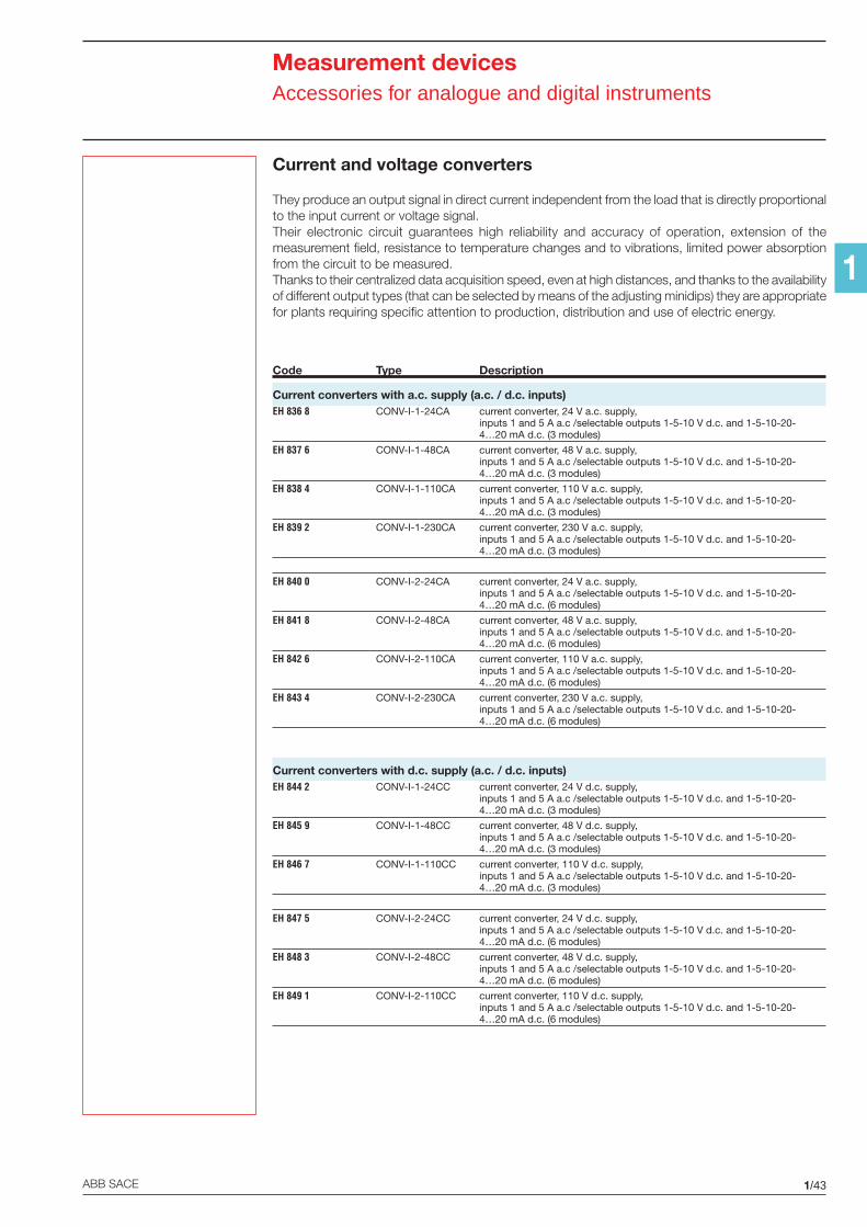
1/43ABB SACE
1
Measurement devicesAccessories for analogue and digital instruments
Current and voltage converters
They produce an output signal in direct current independent from the load that is directly proportionalto the input current or voltage signal.Their electronic circuit guarantees high reliability and accuracy of operation, extension of themeasurement field, resistance to temperature changes and to vibrations, limited power absorptionfrom the circuit to be measured.Thanks to their centralized data acquisition speed, even at high distances, and thanks to the availabilityof different output types (that can be selected by means of the adjusting minidips) they are appropriatefor plants requiring specific attention to production, distribution and use of electric energy.
Code Type Description
Current converters with a.c. supply (a.c. / d.c. inputs)EH 836 8 CONV-I-1-24CA current converter, 24 V a.c. supply,
inputs 1 and 5 A a.c /selectable outputs 1-5-10 V d.c. and 1-5-10-20-4…20 mA d.c. (3 modules)
EH 837 6 CONV-I-1-48CA current converter, 48 V a.c. supply,inputs 1 and 5 A a.c /selectable outputs 1-5-10 V d.c. and 1-5-10-20-4…20 mA d.c. (3 modules)
EH 838 4 CONV-I-1-110CA current converter, 110 V a.c. supply,inputs 1 and 5 A a.c /selectable outputs 1-5-10 V d.c. and 1-5-10-20-4…20 mA d.c. (3 modules)
EH 839 2 CONV-I-1-230CA current converter, 230 V a.c. supply,inputs 1 and 5 A a.c /selectable outputs 1-5-10 V d.c. and 1-5-10-20-4…20 mA d.c. (3 modules)
EH 840 0 CONV-I-2-24CA current converter, 24 V a.c. supply,inputs 1 and 5 A a.c /selectable outputs 1-5-10 V d.c. and 1-5-10-20-4…20 mA d.c. (6 modules)
EH 841 8 CONV-I-2-48CA current converter, 48 V a.c. supply,inputs 1 and 5 A a.c /selectable outputs 1-5-10 V d.c. and 1-5-10-20-4…20 mA d.c. (6 modules)
EH 842 6 CONV-I-2-110CA current converter, 110 V a.c. supply,inputs 1 and 5 A a.c /selectable outputs 1-5-10 V d.c. and 1-5-10-20-4…20 mA d.c. (6 modules)
EH 843 4 CONV-I-2-230CA current converter, 230 V a.c. supply,inputs 1 and 5 A a.c /selectable outputs 1-5-10 V d.c. and 1-5-10-20-4…20 mA d.c. (6 modules)
Current converters with d.c. supply (a.c. / d.c. inputs)EH 844 2 CONV-I-1-24CC current converter, 24 V d.c. supply,
inputs 1 and 5 A a.c /selectable outputs 1-5-10 V d.c. and 1-5-10-20-4…20 mA d.c. (3 modules)
EH 845 9 CONV-I-1-48CC current converter, 48 V d.c. supply,inputs 1 and 5 A a.c /selectable outputs 1-5-10 V d.c. and 1-5-10-20-4…20 mA d.c. (3 modules)
EH 846 7 CONV-I-1-110CC current converter, 110 V d.c. supply,inputs 1 and 5 A a.c /selectable outputs 1-5-10 V d.c. and 1-5-10-20-4…20 mA d.c. (3 modules)
EH 847 5 CONV-I-2-24CC current converter, 24 V d.c. supply,inputs 1 and 5 A a.c /selectable outputs 1-5-10 V d.c. and 1-5-10-20-4…20 mA d.c. (6 modules)
EH 848 3 CONV-I-2-48CC current converter, 48 V d.c. supply,inputs 1 and 5 A a.c /selectable outputs 1-5-10 V d.c. and 1-5-10-20-4…20 mA d.c. (6 modules)
EH 849 1 CONV-I-2-110CC current converter, 110 V d.c. supply,inputs 1 and 5 A a.c /selectable outputs 1-5-10 V d.c. and 1-5-10-20-4…20 mA d.c. (6 modules)
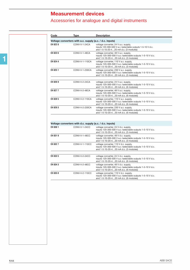
1/44 ABB SACE
1
Measurement devicesAccessories for analogue and digital instruments
Code Type Description
Voltage converters with a.c. supply (a.c. / d.c. inputs)EH 822 8 CONV-V-1-24CA voltage converter, 24 V a.c. supply,
inputs 120-300-500 V a.c /selectable outputs 1-5-10 V d.c.and 1-5-10-20-4…20 mA d.c. (3 modules)
EH 823 6 CONV-V-1-48CA voltage converter, 48 V a.c. supply,inputs 120-300-500 V a.c /selectable outputs 1-5-10 V d.c.and 1-5-10-20-4…20 mA d.c. (3 modules)
EH 824 4 CONV-V-1-110CA voltage converter, 110 V a.c. supply,inputs 120-300-500 V a.c /selectable outputs 1-5-10 V d.c.and 1-5-10-20-4…20 mA d.c. (3 modules)
EH 825 1 CONV-V-1-230CA voltage converter, 230 V a.c. supply,inputs 120-300-500 V a.c /selectable outputs 1-5-10 V d.c.and 1-5-10-20-4…20 mA d.c. (3 modules)
EH 826 9 CONV-V-2-24CA voltage converter, 24 V a.c. supply,inputs 120-300-500 V a.c /selectable outputs 1-5-10 V d.c.and 1-5-10-20-4…20 mA d.c. (6 modules)
EH 827 7 CONV-V-2-48CA voltage converter, 48 V a.c. supply,inputs 120-300-500 V a.c /selectable outputs 1-5-10 V d.c.and 1-5-10-20-4…20 mA d.c. (6 modules)
EH 828 5 CONV-V-2-110CA voltage converter, 110 V a.c. supply,inputs 120-300-500 V a.c /selectable outputs 1-5-10 V d.c.and 1-5-10-20-4…20 mA d.c. (6 modules)
EH 829 3 CONV-V-2-230CA voltage converter, 230 V a.c. supply,inputs 120-300-500 V a.c /selectable outputs 1-5-10 V d.c.and 1-5-10-20-4…20 mA d.c. (6 modules)
Voltage converters with d.c. supply (a.c. / d.c. inputs)EH 830 1 CONV-V-1-24CC voltage converter, 24 V d.c. supply,
inputs 120-300-500 V a.c /selectable outputs 1-5-10 V d.c.and 1-5-10-20-4…20 mA d.c. (3 modules)
EH 831 9 CONV-V-1-48CC voltage converter, 48 V d.c. supply,inputs 120-300-500 V a.c /selectable outputs 1-5-10 V d.c.and 1-5-10-20-4…20 mA d.c. (3 modules)
EH 832 7 CONV-V-1-110CC voltage converter, 110 V d.c. supply,inputs 120-300-500 V a.c /selectable outputs 1-5-10 V d.c.and 1-5-10-20-4…20 mA d.c. (3 modules)
EH 833 5 CONV-V-2-24CC voltage converter, 24 V d.c. supply,inputs 120-300-500 V a.c /selectable outputs 1-5-10 V d.c.and 1-5-10-20-4…20 mA d.c. (6 modules)
EH 834 3 CONV-V-2-48CC voltage converter, 48 V d.c. supply,inputs 120-300-500 V a.c /selectable outputs 1-5-10 V d.c.and 1-5-10-20-4…20 mA d.c. (6 modules)
EH 835 0 CONV-V-2-110CC voltage converter, 110 V d.c. supply,inputs 120-300-500 V a.c /selectable outputs 1-5-10 V d.c.and 1-5-10-20-4…20 mA d.c. (6 modules)
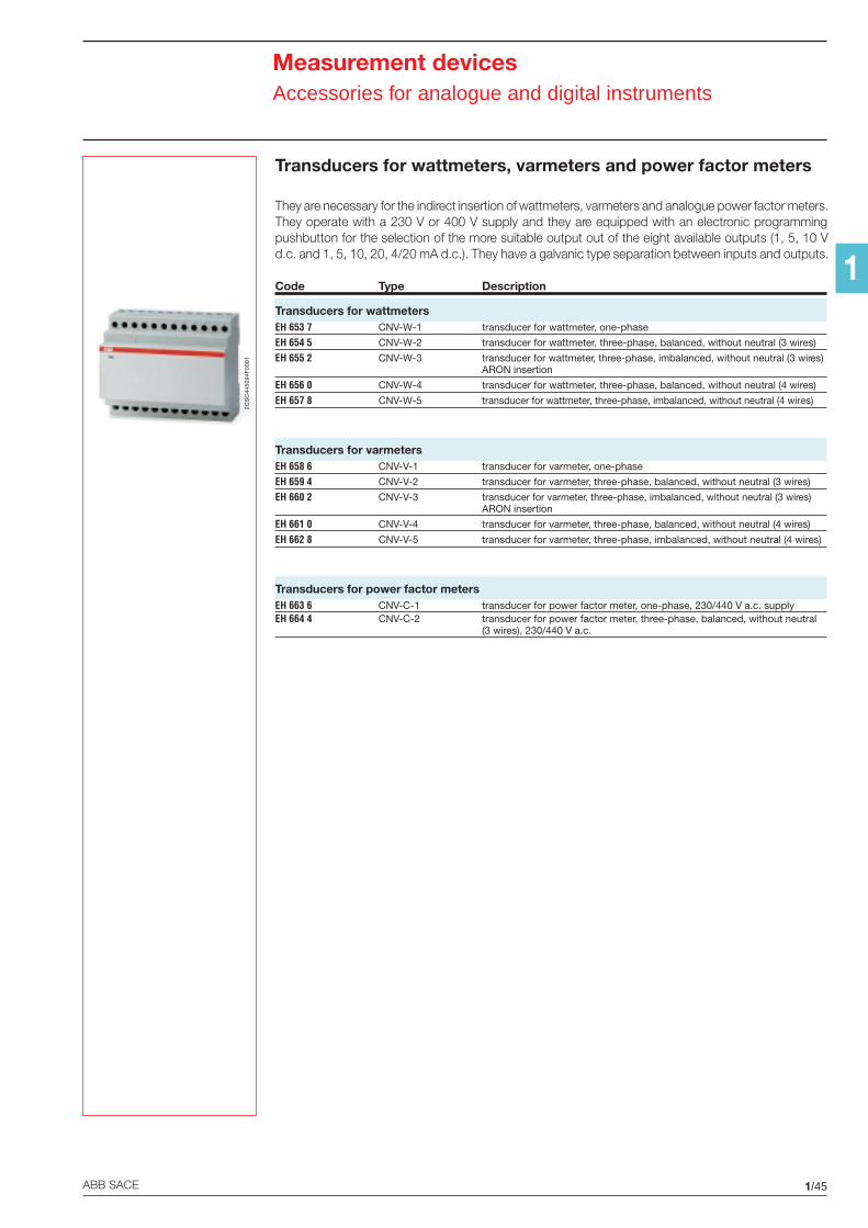
1/45ABB SACE
1
Measurement devicesAccessories for analogue and digital instruments
Transducers for wattmeters, varmeters and power factor meters
They are necessary for the indirect insertion of wattmeters, varmeters and analogue power factor meters.They operate with a 230 V or 400 V supply and they are equipped with an electronic programmingpushbutton for the selection of the more suitable output out of the eight available outputs (1, 5, 10 Vd.c. and 1, 5, 10, 20, 4/20 mA d.c.). They have a galvanic type separation between inputs and outputs.
Code Type Description
Transducers for wattmetersEH 653 7 CNV-W-1 transducer for wattmeter, one-phase
EH 654 5 CNV-W-2 transducer for wattmeter, three-phase, balanced, without neutral (3 wires)
EH 655 2 CNV-W-3 transducer for wattmeter, three-phase, imbalanced, without neutral (3 wires)ARON insertion
EH 656 0 CNV-W-4 transducer for wattmeter, three-phase, balanced, without neutral (4 wires)
EH 657 8 CNV-W-5 transducer for wattmeter, three-phase, imbalanced, without neutral (4 wires)
Transducers for varmetersEH 658 6 CNV-V-1 transducer for varmeter, one-phase
EH 659 4 CNV-V-2 transducer for varmeter, three-phase, balanced, without neutral (3 wires)
EH 660 2 CNV-V-3 transducer for varmeter, three-phase, imbalanced, without neutral (3 wires)ARON insertion
EH 661 0 CNV-V-4 transducer for varmeter, three-phase, balanced, without neutral (4 wires)
EH 662 8 CNV-V-5 transducer for varmeter, three-phase, imbalanced, without neutral (4 wires)
Transducers for power factor metersEH 663 6 CNV-C-1 transducer for power factor meter, one-phase, 230/440 V a.c. supplyEH 664 4 CNV-C-2 transducer for power factor meter, three-phase, balanced, without neutral
(3 wires), 230/440 V a.c.
2CS
C44
5094
F00
01
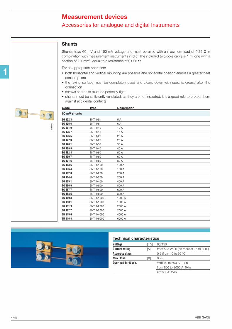
1/46 ABB SACE
1
Measurement devicesAccessories for analogue and digital Instruments
Shunts
Shunts have 60 mV and 150 mV voltage and must be used with a maximum load of 0.25 Ω incombination with measurement instruments in d.c. The included two-pole cable is 1 m long with asection of 1.4 mm2, equal to a resistance of 0.026 Ω.
For an appropriate operation:
• both horizontal and vertical mounting are possible (the horizontal position enables a greater heatconsumption)
• the faying surface must be completely used and clean; cover with specific grease after theconnection
• screws and bolts must be perfectly tight• shunts must be sufficiently ventilated; as they are not insulated, it is a good rule to protect them
against accidental contacts.
Code Type Description
60 mV shunts
EG 132 3 SNT 1/5 5 A
EG 135 6 SNT 1/6 6 A
EG 181 0 SNT 1/10 10 A
EG 125 7 SNT 1/15 15 A
EG 126 5 SNT 1/20 20 A
EG 127 3 SNT 1/25 25 A
EG 128 1 SNT 1/30 30 A
EG 129 9 SNT 1/40 40 A
EG 182 8 SNT 1/50 50 A
EG 130 7 SNT 1/60 60 A
EG 131 5 SNT 1/80 80 A
EG 183 6 SNT 1/100 100 A
EG 136 4 SNT 1/150 150 A
EG 162 0 SNT 1/200 200 A
EG 184 4 SNT 1/250 250 A
EG 185 1 SNT 1/400 400 A
EG 186 9 SNT 1/500 500 A
EG 187 7 SNT 1/600 600 A
EG 188 5 SNT 1/800 800 A
EG 189 3 SNT 1/1000 1000 A
EG 190 1 SNT 1/1500 1500 A
EG 191 9 SNT 1/2000 2000 A
EG 192 7 SNT 1/2500 2500 A
EH 915 0 SNT 1/4000 4000 A
EH 916 8 SNT 1/6000 6000 A
TEP
M02
89
Technical characteristicsVoltage [mV] 60/150
Current rating [A] from 5 to 2500 (on request up to 8000)
Accuracy class 0.5 (from 10 to 30 °C)
Max. load [Ω] 0.25
Overload for 5 sec. from 10 to 500 A : 1xIn
from 600 to 2000 A: 5xIn
at 2500A: 2xIn
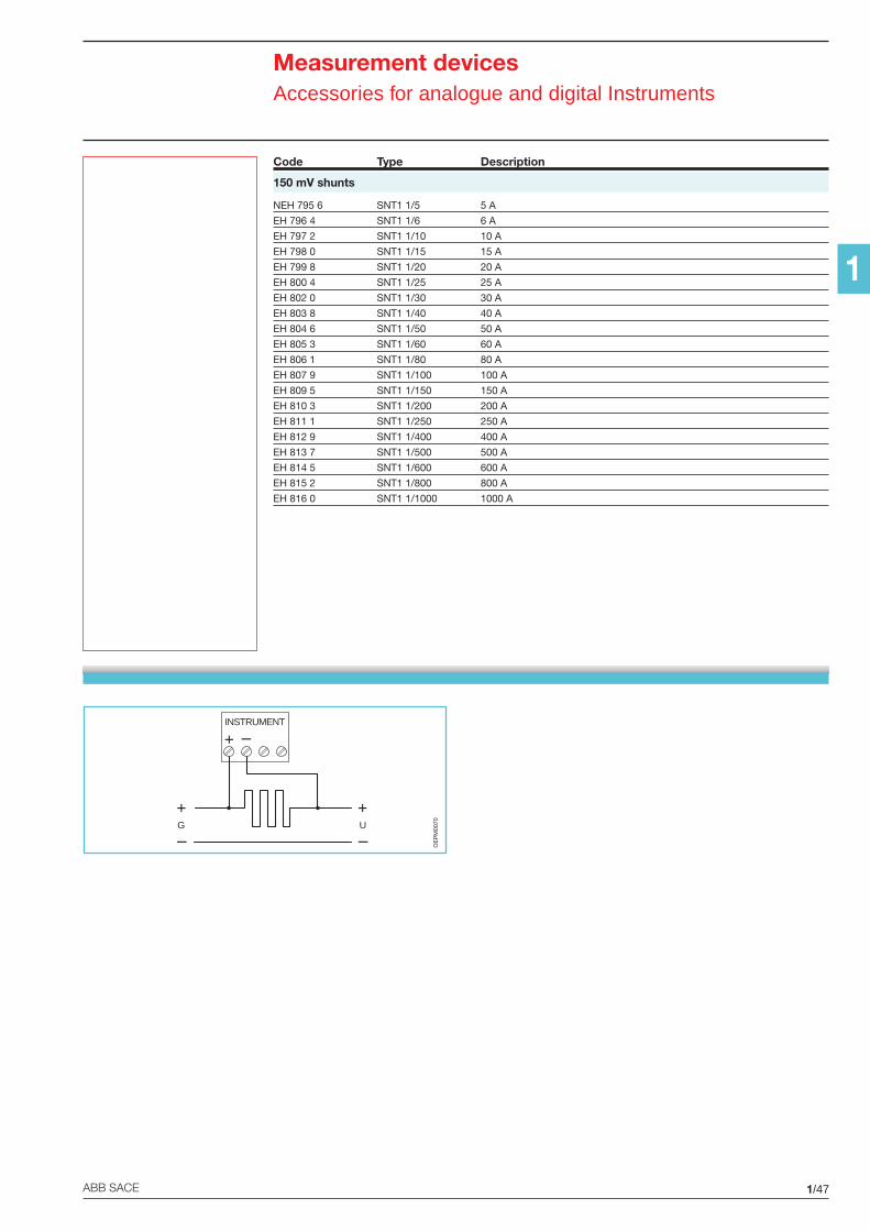
1/47ABB SACE
1
Code Type Description
150 mV shunts
NEH 795 6 SNT1 1/5 5 A
EH 796 4 SNT1 1/6 6 A
EH 797 2 SNT1 1/10 10 A
EH 798 0 SNT1 1/15 15 A
EH 799 8 SNT1 1/20 20 A
EH 800 4 SNT1 1/25 25 A
EH 802 0 SNT1 1/30 30 A
EH 803 8 SNT1 1/40 40 A
EH 804 6 SNT1 1/50 50 A
EH 805 3 SNT1 1/60 60 A
EH 806 1 SNT1 1/80 80 A
EH 807 9 SNT1 1/100 100 A
EH 809 5 SNT1 1/150 150 A
EH 810 3 SNT1 1/200 200 A
EH 811 1 SNT1 1/250 250 A
EH 812 9 SNT1 1/400 400 A
EH 813 7 SNT1 1/500 500 A
EH 814 5 SNT1 1/600 600 A
EH 815 2 SNT1 1/800 800 A
EH 816 0 SNT1 1/1000 1000 A
INSTRUMENT
G U
OE
PM
0070
Measurement devicesAccessories for analogue and digital Instruments
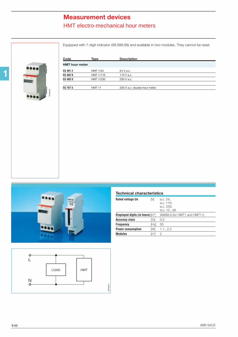
1/48 ABB SACE
1
Measurement devicesHMT electro-mechanical hour meters
Equipped with 7-digit indicator (99.999,99) and available in two modules. They cannot be reset.
Code Type Description
HMT hour meter
EG 401 2 HMT 1/24 24 V a.c.
EG 402 0 HMT 1/110 110 V a.c.
EG 403 8 HMT 1/230 230 V a.c.
EG 107 5 HMT 11 230 V a.c. double hour meter
TEP
M02
91
Technical characteristicsRated voltage Un [V] a.c. 24;
a.c. 110;a.c. 230;d.c. 12...48
Displayed digits (in hours) [n°] 99999.9 (for HMT1 and HMT11)
Accuracy class [%] 0.5
Frequency [Hz] 50
Power consumption [W] 1.1...2.2
Modules [n°] 2
OE
PM
0071
L
N
LOAD HMT
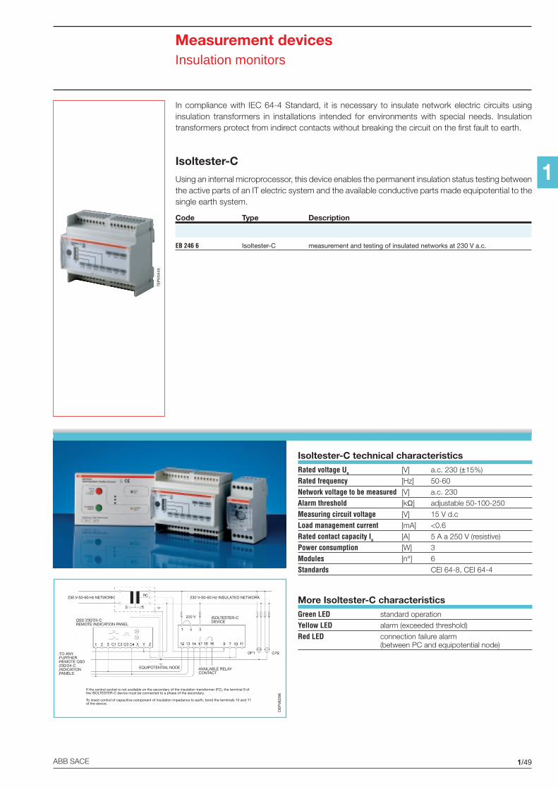
1/49ABB SACE
1
In compliance with IEC 64-4 Standard, it is necessary to insulate network electric circuits usinginsulation transformers in installations intended for environments with special needs. Insulationtransformers protect from indirect contacts without breaking the circuit on the first fault to earth.
Isoltester-C
Using an internal microprocessor, this device enables the permanent insulation status testing betweenthe active parts of an IT electric system and the available conductive parts made equipotential to thesingle earth system.
Code Type Description
EB 246 6 Isoltester-C measurement and testing of insulated networks at 230 V a.c.
TEP
M04
49
Isoltester-C technical characteristicsRated voltage Un [V] a.c. 230 (±15%)
Rated frequency [Hz] 50-60
Network voltage to be measured [V] a.c. 230
Alarm threshold [kΩ] adjustable 50-100-250
Measuring circuit voltage [V] 15 V d.c
Load management current [mA] <0.6
Rated contact capacity In [A] 5 A a 250 V (resistive)
Power consumption [W] 3
Modules [n°] 6
Standards CEI 64-8, CEI 64-4
More Isoltester-C characteristicsGreen LED standard operation
Yellow LED alarm (exceeded threshold)
Red LED connection failure alarm(between PC and equipotential node)
Measurement devicesInsulation monitors
230 V-50-60 Hz INSULATED NETWORK230 V-50-60 Hz NETWORK
QSD 230/24-CREMOTE INDICATION PANEL
ISOLTESTER-CDEVICE
TO ANYFURTHERREMOTE QSD230/24-CINDICATIONPANELS
AVAILABLE RELAYCONTACT
EQUIPOTENTIAL NODE
If the central socket is not available on the secondary of the insulation transformer (FC), the terminal 9 ofthe ISOLTESTER-C device must be connected to a phase of the secondary.
To insert control of capacitive component of insulation impedance to earth, bond the terminals 10 and 11of the device.
OE
PM
0296
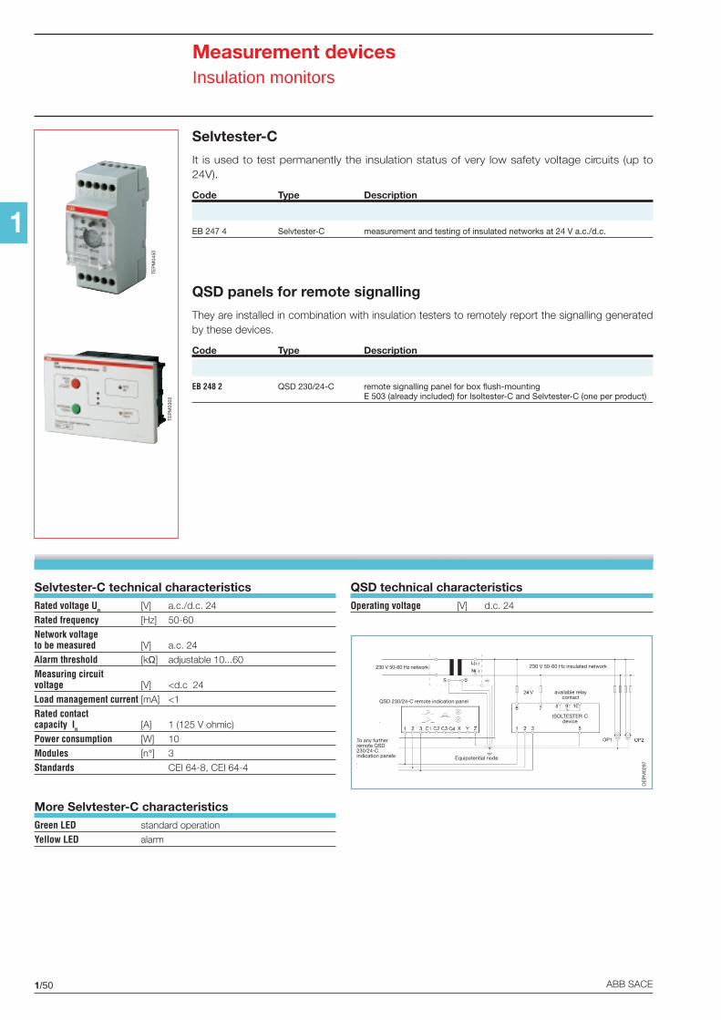
1/50 ABB SACE
1
Selvtester-C
It is used to test permanently the insulation status of very low safety voltage circuits (up to24V).
Code Type Description
EB 247 4 Selvtester-C measurement and testing of insulated networks at 24 V a.c./d.c.
QSD panels for remote signalling
They are installed in combination with insulation testers to remotely report the signalling generatedby these devices.
Code Type Description
EB 248 2 QSD 230/24-C remote signalling panel for box flush-mountingE 503 (already included) for Isoltester-C and Selvtester-C (one per product)
TEP
M04
50
TEP
M03
02
Selvtester-C technical characteristicsRated voltage Un [V] a.c./d.c. 24
Rated frequency [Hz] 50-60
Network voltageto be measured [V] a.c. 24
Alarm threshold [kΩ] adjustable 10...60
Measuring circuitvoltage [V] <d.c 24
Load management current [mA] <1
Rated contactcapacity In [A] 1 (125 V ohmic)
Power consumption [W] 10
Modules [n°] 3
Standards CEI 64-8, CEI 64-4
More Selvtester-C characteristicsGreen LED standard operation
Yellow LED alarm
QSD technical characteristicsOperating voltage [V] d.c. 24
230 V 50-60 Hz network 230 V 50-60 Hz insulated network
QSD 230/24-C remote indication panel
available relaycontact
ISOLTESTER-Cdevice
To any furtherremote QSD230/24-Cindication panels Equipotential node
Measurement devicesInsulation monitors
OE
PM
0297
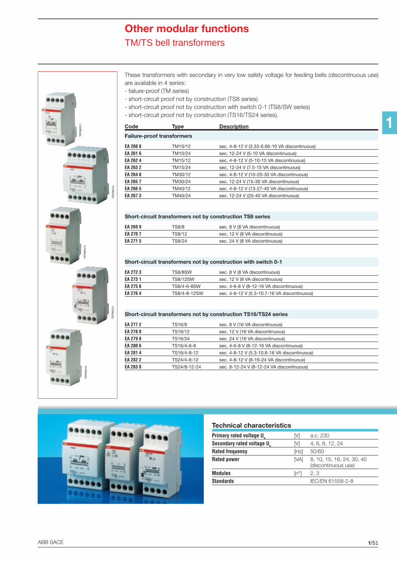
1/51ABB SACE
1
Other modular functionsTM/TS bell transformers
These transformers with secondary in very low safety voltage for feeding bells (discontinuous use)are available in 4 series:- failure-proof (TM series)- short-circuit proof not by construction (TS8 series)- short-circuit proof not by construction with switch 0-1 (TS8/SW series)- short-circuit proof not by construction (TS16/TS24 series).
Code Type Description
Failure-proof transformers
EA 260 8 TM10/12 sec. 4-8-12 V (3.33-6.66-10 VA discontinuous)
EA 261 6 TM10/24 sec. 12-24 V (5-10 VA discontinuous)
EA 262 4 TM15/12 sec. 4-8-12 V (5-10-15 VA discontinuous)
EA 263 2 TM15/24 sec. 12-24 V (7.5-15 VA discontinuous)
EA 264 0 TM30/12 sec. 4-8-12 V (10-20-30 VA discontinuous)
EA 265 7 TM30/24 sec. 12-24 V (15-30 VA discontinuous)
EA 266 5 TM40/12 sec. 4-8-12 V (13-27-40 VA discontinuous)
EA 267 3 TM40/24 sec. 12-24 V (20-40 VA discontinuous)
Short-circuit transformers not by construction TS8 series
EA 269 9 TS8/8 sec. 8 V (8 VA discontinuous)
EA 270 7 TS8/12 sec. 12 V (8 VA discontinuous)
EA 271 5 TS8/24 sec. 24 V (8 VA discontinuous)
Short-circuit transformers not by construction with switch 0-1
EA 272 3 TS8/8SW sec. 8 V (8 VA discontinuous)
EA 273 1 TS8/12SW sec. 12 V (8 VA discontinuous)
EA 275 6 TS8/4-6-8SW sec. 4-6-8 V (8-12-16 VA discontinuous)
EA 276 4 TS8/4-8-12SW sec. 4-8-12 V (5.3-10.7-16 VA discontinuous)
Short-circuit transformers not by construction TS16/TS24 series
EA 277 2 TS16/8 sec. 8 V (16 VA discontinuous)
EA 278 0 TS16/12 sec. 12 V (16 VA discontinuous)
EA 279 8 TS16/24 sec. 24 V (16 VA discontinuous)
EA 280 6 TS16/4-6-8 sec. 4-6-8 V (8-12-16 VA discontinuous)
EA 281 4 TS16/4-8-12 sec. 4-8-12 V (5.3-10.6-16 VA discontinuous)
EA 282 2 TS24/4-8-12 sec. 4-8-12 V (8-16-24 VA discontinuous)
EA 283 0 TS24/8-12-24 sec. 8-12-24 V (8-12-24 VA discontinuous)
Technical characteristicsPrimary rated voltage Un [V] a.c. 230
Secondary rated voltage Un [V] 4, 6, 8, 12, 24
Rated frequency [Hz] 50/60
Rated power [VA] 8, 10, 15, 16, 24, 30, 40(discontinuous use)
Modules [n°] 2, 3
Standards IEC/EN 61558-2-8
TEP
M03
15
TEP
M03
14
TEP
M03
11
TEP
M03
12
TEP
M03
13
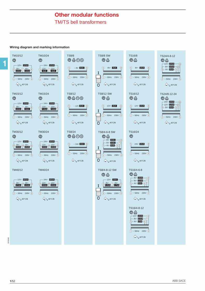
1/52 ABB SACE
1
Other modular functionsTM/TS bell transformers
TS16/4-8-12
5
8
1 4~ 50Hz 230V
76
12V~ 16VA
8V~ 10,6VA4V~ 5,3VA
t 40°C/Ba
TS8/4-6-8 SW
5
8
1 4~ 50Hz 230V
76
8V~ 8VA
6V~ 6VA4V~ 4VA
t 40°C/Ba
TS16/4-6-8
5
8
1 4~ 50Hz 230V
76
8V~ 16VA
6V~ 12VA4V~ 8VA
t 40°C/Ba
TS8/4-8-12 SW
5 8
4 4
12V~
~ 50Hz 230V
7
8VA
8V~5,3VA
4V~2,7VA
t 40°C/Ba
TM40/24
8 11
2 5
24V~
~ 50Hz 230V
10
40VA
12V~20VA
12V~20VA
t 40°C/BaF
TM40/12
8 11
2 5
12V~
~ 50Hz 230V
10
40VA
8V~27VA
4V~13VA
t 40°C/BaF
TM30/12
8 11
2 5
12V~
~ 50Hz 230V
10
30VA
8V~20VA
4V~10VA
t 40°C/BaF
TM30/24
8 11
2 5
24V~
~ 50Hz 230V
10
30VA
12V~15VA
12V~15VA
t 40°C/BaF
TS16/24
5 8
1 4~ 50Hz 230V
24V~ 16VA
t 40°C/Ba
TS24/4-8-12
8
11
2 5~ 50Hz 230V
109
12V~ 24VA
8V~ 16VA4V~ 8VA
t 40°C/Ba
TS16/12
5 8
1 4~ 50Hz 230V
12V~ 16VA
t 40°C/Ba
TM15/24
5 8
1 4
24V~
~ 50Hz 230V
7
15VA
12V~7,5VA
12V~7,5VA
t 40°C/BaF
TM15/12
5 8
1 4
12V~
~ 50Hz 230V
7
15VA
8V~10VA
4V~5VA
t 40°C/BaF
TM10/12
5 8
1 4
12V~
~ 50Hz 230V
7
10VA
8V~6.66VA
4V~3.33VA
t 40°C/BaF
TM10/24
5 8
1 4
24V~
~ 50Hz 230V
7
10VA
12V~5VA
12V~5VA
t 40°C/BaF
TS16/8
5 8
1 4~ 50Hz 230V
8V~ 16VA
t 40°C/Ba
TS24/8-12-24
8
11
2 5~ 50Hz 230V
109
24V~ 24VA
12V~ 12VA8V~ 8VA
t 40°C/Ba
TS8/8 SW
5 8
1 4~ 50Hz 230V
8V~ 8VA
t 40°C/Ba
TS8/12 SW
5 8
1 4~ 50Hz 230V
12V~ 8VA
t 40°C/Ba
TS8/8
5 8
1 4
~ 8V
~ 50Hz 230V
t 40°C/Ba
8VA
TS8/12
5 8
1 4
~ 12V
~ 50Hz 230V
t 40°C/Ba
8VA
8VA
TS8/24
5 8
1 4
~ 24V
~ 50Hz 230V
t 40°C/Ba
OE
PM
080
Wiring diagram and marking information
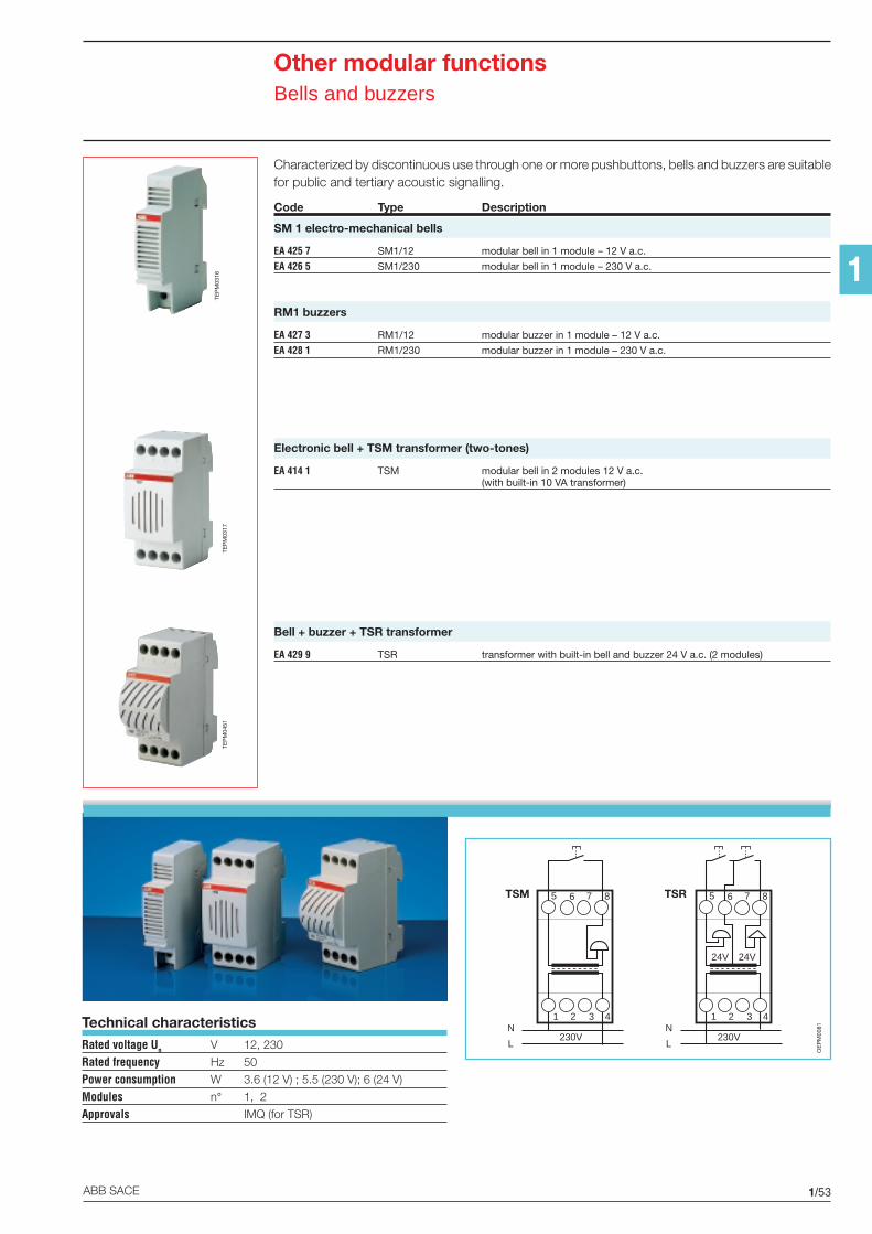
1/53ABB SACE
1
Other modular functionsBells and buzzers
Characterized by discontinuous use through one or more pushbuttons, bells and buzzers are suitablefor public and tertiary acoustic signalling.
Code Type Description
SM 1 electro-mechanical bells
EA 425 7 SM1/12 modular bell in 1 module – 12 V a.c.
EA 426 5 SM1/230 modular bell in 1 module – 230 V a.c.
RM1 buzzers
EA 427 3 RM1/12 modular buzzer in 1 module – 12 V a.c.
EA 428 1 RM1/230 modular buzzer in 1 module – 230 V a.c.
Electronic bell + TSM transformer (two-tones)
EA 414 1 TSM modular bell in 2 modules 12 V a.c.(with built-in 10 VA transformer)
Bell + buzzer + TSR transformer
EA 429 9 TSR transformer with built-in bell and buzzer 24 V a.c. (2 modules)
Technical characteristicsRated voltage Un V 12, 230
Rated frequency Hz 50
Power consumption W 3.6 (12 V) ; 5.5 (230 V); 6 (24 V)
Modules n° 1, 2
Approvals IMQ (for TSR)
TEP
M03
17TE
PM
0316
5 6 7 8TSM
1 2 3 4
230VN
L
5 6 7 8TSR
1 2 3 4
230VN
L
24V 24V
OE
PM
0081
TEP
M04
51
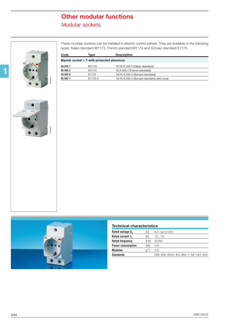
1/54 ABB SACE
1
Other modular functionsModular sockets
These modular sockets can be installed in electric control panels. They are available in the followingtypes: Italian standard M1173, French standard M1174 and Schuko standard E1175.
Code Type Description
Bipolar socket + T with protected alveolous
EA 944 7 M1173 10/16 A 250 V (Italian standard)
EA 945 4 M1174 16 A 250 V (French standard)
EA 943 9 E1175 10/16 A 250 V (Schuko standard)
EA 942 1 E1175-C 10/16 A 250 V (Schuko standard) with cover
TEP
M03
19
Technical characteristicsRated voltage Un [V] a.c. up to 250
Rated current In [A] 10...16
Rated frequency [Hz] 50/60
Power consumption [W] 0.6
Modules [n°] 2.5
Standards DIN VDE 0620; IEC 884-1; NF C61-303
TEP
M04
52
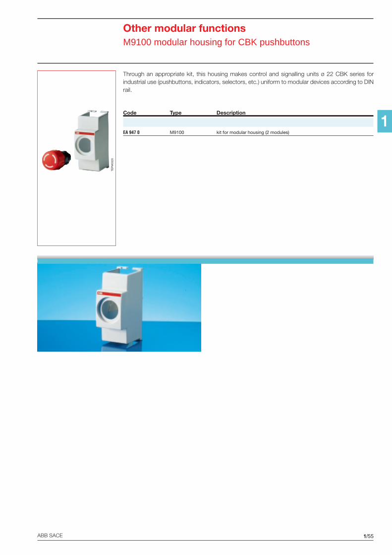
1/55ABB SACE
1
Other modular functionsM9100 modular housing for CBK pushbuttons
Through an appropriate kit, this housing makes control and signalling units ø 22 CBK series forindustrial use (pushbuttons, indicators, selectors, etc.) uniform to modular devices according to DINrail.
Code Type Description
EA 947 0 M9100 kit for modular housing (2 modules)
TEP
M03
20
2/1ABB SACE
2
Technical details
Contents
Protection devices
RD2 residual current monitors and toroidal transformers ..........................................................2/2
E 930 fuse holders ...................................................................................................................2/5
M2160 - M2060 fuse switches .................................................................................................2/6
Command devices
E 259 installation relays ............................................................................................................2/7
E 250 latching relays ................................................................................................................2/9
Load management devices
LSS1/2 load shedding switches ............................................................................................. 2/11
Max./min. current/voltage ammetric and voltmetric relays ......................................................2/12
Measurement devices
Analogue and digital measurement instruments .....................................................................2/14
Accessories for analogue and digital measurements instruments ...........................................2/18
Insulation monitors .................................................................................................................2/31
Other modular functions
TM/TS bell transformers .........................................................................................................2/32
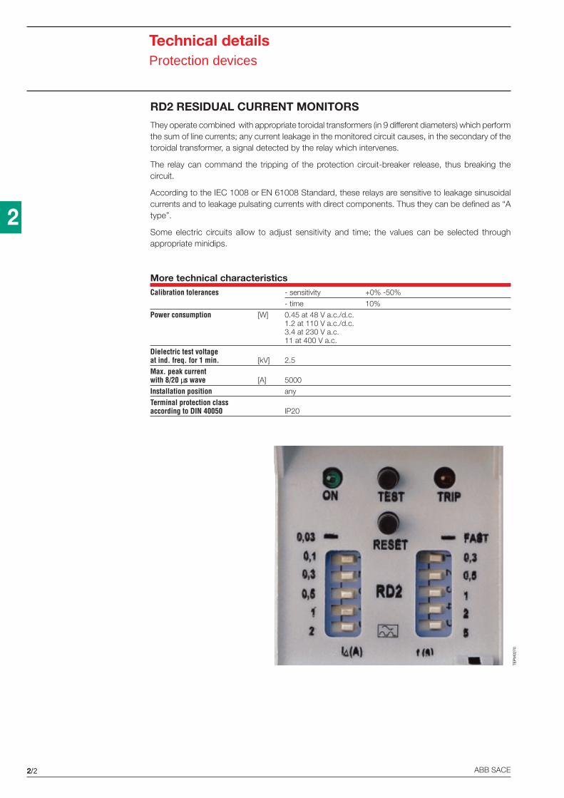
2/2 ABB SACE
2
RD2 RESIDUAL CURRENT MONITORS
They operate combined with appropriate toroidal transformers (in 9 different diameters) which performthe sum of line currents; any current leakage in the monitored circuit causes, in the secondary of thetoroidal transformer, a signal detected by the relay which intervenes.
The relay can command the tripping of the protection circuit-breaker release, thus breaking thecircuit.
According to the IEC 1008 or EN 61008 Standard, these relays are sensitive to leakage sinusoidalcurrents and to leakage pulsating currents with direct components. Thus they can be defined as “Atype”.
Some electric circuits allow to adjust sensitivity and time; the values can be selected throughappropriate minidips.
More technical characteristicsCalibration tolerances - sensitivity +0% -50%
- time 10%
Power consumption [W] 0.45 at 48 V a.c./d.c.1.2 at 110 V a.c./d.c.3.4 at 230 V a.c.11 at 400 V a.c.
Dielectric test voltageat ind. freq. for 1 min. [kV] 2.5
Max. peak currentwith 8/20 µs wave [A] 5000
Installation position any
Terminal protection classaccording to DIN 40050 IP20
TEP
M02
70
Technical detailsProtection devices
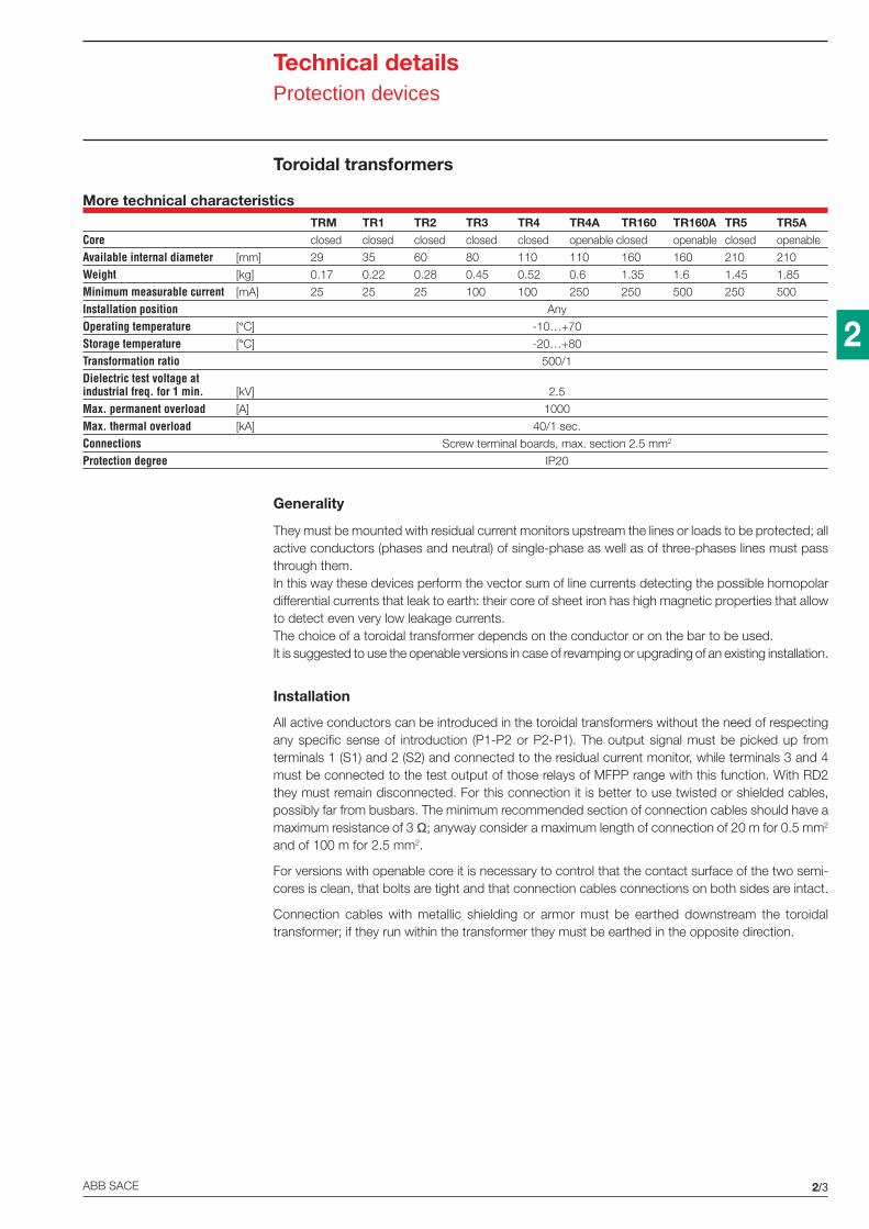
2/3ABB SACE
2
Toroidal transformers
Generality
They must be mounted with residual current monitors upstream the lines or loads to be protected; allactive conductors (phases and neutral) of single-phase as well as of three-phases lines must passthrough them.In this way these devices perform the vector sum of line currents detecting the possible homopolardifferential currents that leak to earth: their core of sheet iron has high magnetic properties that allowto detect even very low leakage currents.The choice of a toroidal transformer depends on the conductor or on the bar to be used.It is suggested to use the openable versions in case of revamping or upgrading of an existing installation.
Installation
All active conductors can be introduced in the toroidal transformers without the need of respectingany specific sense of introduction (P1-P2 or P2-P1). The output signal must be picked up fromterminals 1 (S1) and 2 (S2) and connected to the residual current monitor, while terminals 3 and 4must be connected to the test output of those relays of MFPP range with this function. With RD2they must remain disconnected. For this connection it is better to use twisted or shielded cables,possibly far from busbars. The minimum recommended section of connection cables should have amaximum resistance of 3 Ω; anyway consider a maximum length of connection of 20 m for 0.5 mm2
and of 100 m for 2.5 mm2.
For versions with openable core it is necessary to control that the contact surface of the two semi-cores is clean, that bolts are tight and that connection cables connections on both sides are intact.
Connection cables with metallic shielding or armor must be earthed downstream the toroidaltransformer; if they run within the transformer they must be earthed in the opposite direction.
Technical detailsProtection devices
More technical characteristicsTRM TR1 TR2 TR3 TR4 TR4A TR160 TR160A TR5 TR5A
Core closed closed closed closed closed openable closed openable closed openable
Available internal diameter [mm] 29 35 60 80 110 110 160 160 210 210
Weight [kg] 0.17 0.22 0.28 0.45 0.52 0.6 1.35 1.6 1.45 1.85
Minimum measurable current [mA] 25 25 25 100 100 250 250 500 250 500
Installation position Any
Operating temperature [°C] -10…+70
Storage temperature [°C] -20…+80
Transformation ratio 500/1
Dielectric test voltage atindustrial freq. for 1 min. [kV] 2.5
Max. permanent overload [A] 1000
Max. thermal overload [kA] 40/1 sec.
Connections Screw terminal boards, max. section 2.5 mm2
Protection degree IP20
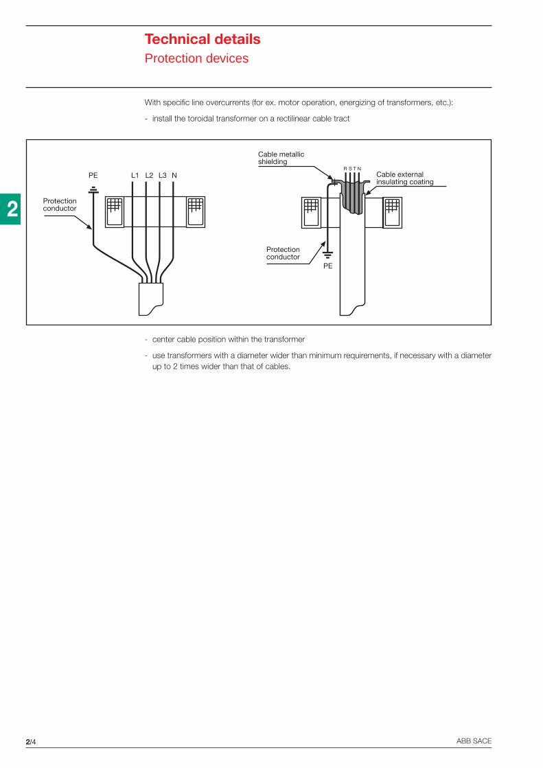
2/4 ABB SACE
2
Technical detailsProtection devices
Protectionconductor
L1 L2 L3 N Cable externalinsulating coating
Cable metallicshielding
Protectionconductor
R S T N
PE
PE
With specific line overcurrents (for ex. motor operation, energizing of transformers, etc.):
- install the toroidal transformer on a rectilinear cable tract
- center cable position within the transformer
- use transformers with a diameter wider than minimum requirements, if necessary with a diameterup to 2 times wider than that of cables.
2/5ABB SACE
2
Technical detailsProtection devices
Power consumption in Watt at rated current
Of the fuse Fuses Fuses FusesIn [A] 10.3x38 14x51 22x58
aM aM aM1 0.082 0.124 0.17 0.25 0.306 0.30 0.30 0.458 0.35 0.40 0.551 0.40 0.50 0.6012 0.45 0.65 0.7516 0.70 0.90 0.9020 1.00 1.00 1.1025 1.20 1.20 1.3532 1.50 1.55 1.6040 2.10 1.9045 2.15 2.2050 2.50 3.0063 4.1080 5.20100 6.50125 7.80
E 930 FUSE HOLDERSMore technical characteristicsBreaking capacity that of the cartridge
Dielectric test voltageat ind. freq. for 1 min. 2.5 kV
Terminalsup to 32 A 10 mm2
up to 50 A 25 mm2
up to 125 A 35 mm2
Protection degree IP20
Rated voltage UnE930/32 (10.3x38 fuses) 400 V*
* E930/32 fuse holders comply with IEC EN 60269-3 Standard (fuse for domestic applications) and they have been releasedwith Un=400 V; by construction, they can be used up to 500 V.
Power consumption in Watt at rated current
Of the fuse Fuses Fuses FusesIn [A] 10.3x38 14x51 22x58
gL gL gL1 0.272 0.50 0.804 1.05 0.95 1.456 1.10 1.30 1.608 1.20 1.60 2.1510 1.30 1.90 2.5012 1.50 2.10 2.7016 1.80 2.20 2.7520 2.00 2.30 2.9025 2.30 3.00 3.4032 2.60 3.30 3.6040 3.60 4.5045 4.10 4.8050 5.00 5.5063 6.3580 7.35100 8.75125 12.50
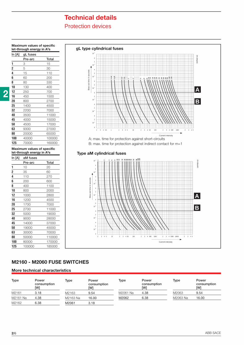
2/6 ABB SACE
2
Technical detailsProtection devices
2 3 4 0.5 1 2 5
4
10 -2
2
4
3 4 5 10 2 3 4 50 100 2 3 4 500 1000 2 3 4
10 -1
2
4
10 0
2
4
10 1
2
4
10 2
2
4
10 3
2
4
10 4
B
A
Blo
w-o
ut ti
me
in s
econ
ds
Current intensity
0,16
0,25
0,5
0,6
1 2 4 6 8 10 12 16 20 25 32 40 50 63 80 100
125
2 3 4 5 10 2 5
4
10 -2
2
4
3 4 50 100 2 3 4 500 1000 2 3 4 5000 10000 2 3 4
10 -1
2
4
10 0
2
4
10 1
2
4
10 2
2
4
10 3
2
4
10 4
B
A
Blo
w-o
ut ti
me
in s
econ
ds
Current intensity
1 2 4 6 8 10 12 16 20 25 32 40 50 63 80 100
125
Maximum values of specificlet-through energy in A2s
In [A] aM fusesPre-arc Total
1 10 202 35 604 110 2706 200 6008 400 110010 800 200012 1000 280016 1200 450020 1700 700025 2700 1100032 5000 1900040 9000 2800045 14000 3700050 19000 4500063 30000 7000080 50000 110000100 80000 170000125 100000 185000
Maximum values of specificlet-through energy in A2s
In [A] gL fusesPre-arc Total
1 3 152 5 304 15 1106 60 2008 80 33010 130 40012 250 70016 450 150020 800 270025 1400 450032 2200 700040 3500 1100045 4000 1500050 4500 1700063 9300 2700080 20000 65000100 40000 100000125 70000 160000
gL type cylindrical fuses
Type aM cylindrical fuses
A: max. time for protection against short-circuitsB: max. time for protection against indirect contact for m=1
A
B
A
B
OE
PM
0142
OE
PM
0142
M2160 - M2060 FUSE SWITCHES
More technical characteristics
Type Powerconsumption[W]
M2161 3.18
M2161 Na 4.38
M2162 6.38
Type Powerconsumption[W]
M2163 9.54
M2163 Na 16.00
M2061 3.18
Type Powerconsumption[W]
M2061 Na 4.38
M2062 6.38
Type Powerconsumption[W]
M2063 9.54
M2063 Na 16.00
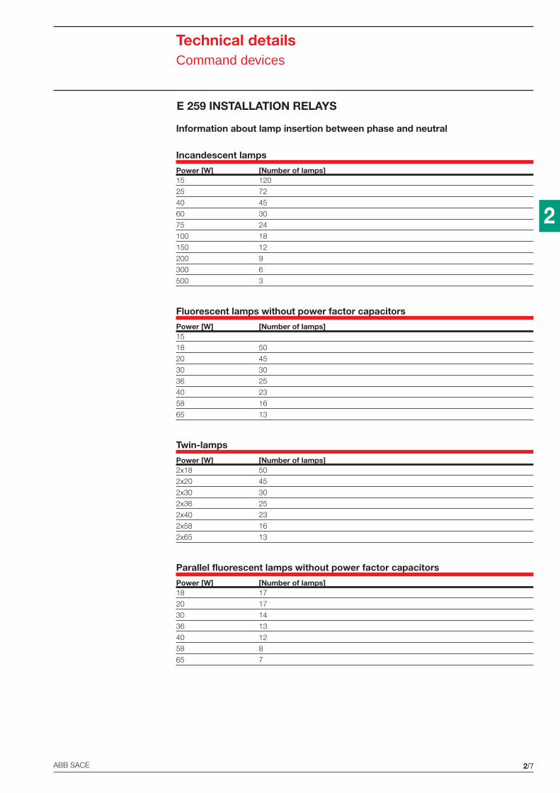
2/7ABB SACE
2
Information about lamp insertion between phase and neutral
Incandescent lamps
Power [W] [Number of lamps]15 120
25 72
40 45
60 30
75 24
100 18
150 12
200 9
300 6
500 3
Fluorescent lamps without power factor capacitors
Power [W] [Number of lamps]15
18 50
20 45
30 30
36 25
40 23
58 16
65 13
Twin-lamps
Power [W] [Number of lamps]2x18 50
2x20 45
2x30 30
2x36 25
2x40 23
2x58 16
2x65 13
Parallel fluorescent lamps without power factor capacitors
Power [W] [Number of lamps]18 17
20 17
30 14
36 13
40 12
58 8
65 7
E 259 INSTALLATION RELAYS
Technical detailsCommand devices
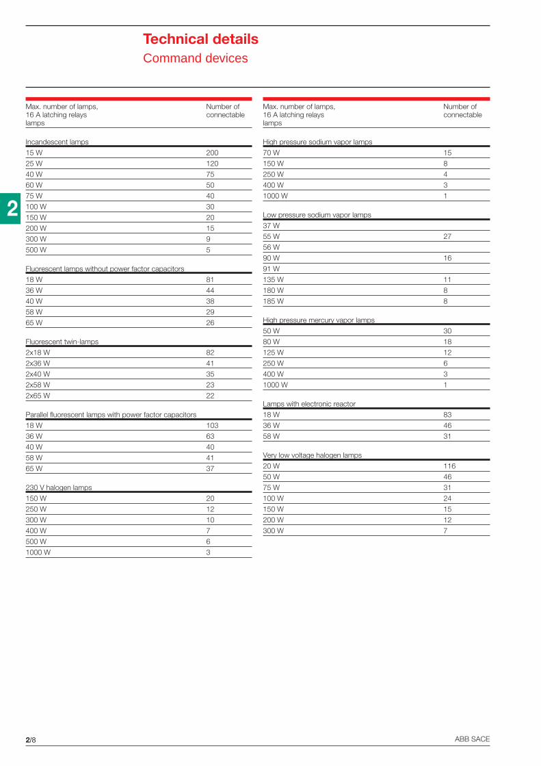
2/8 ABB SACE
2
Technical detailsCommand devices
Max. number of lamps, Number of16 A latching relays connectablelamps
Incandescent lamps
15 W 200
25 W 120
40 W 75
60 W 50
75 W 40
100 W 30
150 W 20
200 W 15
300 W 9
500 W 5
Fluorescent lamps without power factor capacitors
18 W 81
36 W 44
40 W 38
58 W 29
65 W 26
Fluorescent twin-lamps
2x18 W 82
2x36 W 41
2x40 W 35
2x58 W 23
2x65 W 22
Parallel fluorescent lamps with power factor capacitors
18 W 103
36 W 63
40 W 40
58 W 41
65 W 37
230 V halogen lamps
150 W 20
250 W 12
300 W 10
400 W 7
500 W 6
1000 W 3
Max. number of lamps, Number of16 A latching relays connectablelamps
High pressure sodium vapor lamps
70 W 15
150 W 8
250 W 4
400 W 3
1000 W 1
Low pressure sodium vapor lamps
37 W
55 W 27
56 W
90 W 16
91 W
135 W 11
180 W 8
185 W 8
High pressure mercury vapor lamps
50 W 30
80 W 18
125 W 12
250 W 6
400 W 3
1000 W 1
Lamps with electronic reactor
18 W 83
36 W 46
58 W 31
Very low voltage halogen lamps
20 W 116
50 W 46
75 W 31
100 W 24
150 W 15
200 W 12
300 W 7
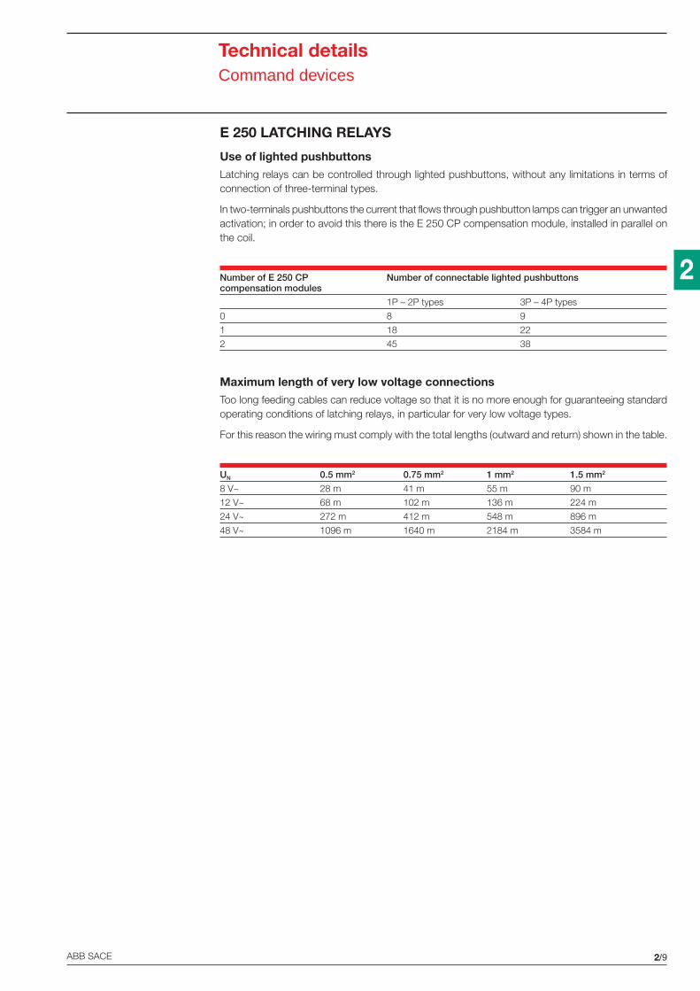
2/9ABB SACE
2
Technical detailsCommand devices
E 250 LATCHING RELAYS
Use of lighted pushbuttonsLatching relays can be controlled through lighted pushbuttons, without any limitations in terms ofconnection of three-terminal types.
In two-terminals pushbuttons the current that flows through pushbutton lamps can trigger an unwantedactivation; in order to avoid this there is the E 250 CP compensation module, installed in parallel onthe coil.
Number of E 250 CP Number of connectable lighted pushbuttonscompensation modules
1P – 2P types 3P – 4P types
0 8 9
1 18 22
2 45 38
Maximum length of very low voltage connectionsToo long feeding cables can reduce voltage so that it is no more enough for guaranteeing standardoperating conditions of latching relays, in particular for very low voltage types.
For this reason the wiring must comply with the total lengths (outward and return) shown in the table.
UN 0.5 mm2 0.75 mm2 1 mm2 1.5 mm2
8 V~ 28 m 41 m 55 m 90 m
12 V~ 68 m 102 m 136 m 224 m
24 V~ 272 m 412 m 548 m 896 m
48 V~ 1096 m 1640 m 2184 m 3584 m
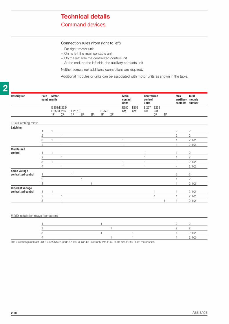
2/10 ABB SACE
2
Connection rules (from right to left)
– Far right: motor unit– On its left the main contacts unit– On the left side the centralized control unit– At the end, on the left side, the auxiliary contacts unit
Neither screws nor additional connections are required.
Additional modules or units can be associated with motor units as shown in the table.
Technical detailsCommand devices
Description Pole Motor Main Centralized Max. Totalnumberunits contact control auxiliary module
units units contacts numberE 251/E 252/ E250 E259 E 257 E258E 256/E 256 E 257 C E 259 CM CM CM CM1P 2P 1P 2P 3P 1P 2P 0P 1P
E 250 latching relays
Latching1 1 2 2
2 1 2 2
3 1 1 1 2 1/2
4 1 1 1 2 1/2
Maintainedcontrol 1 1 1 1 2
2 1 1 1 2
3 1 1 1 - 2 1/2
4 1 1 1 - 2 1/2
Same voltagecentralized control 1 1 2 2
2 1 1 2
3 1 1 2 1/2
Different voltagecentralized control 1 1 1 1 2 1/2
2 1 1 1 2 1/2
3 1 1 1 2 1/2
E 259 installation relays (contactors)
1 1 2 2
2 1 2 2
3 1 1 1 2 1/2
4 1 1 1 2 1/2The 2 exchange contact unit E 259 CM002 (code EA 663 3) can be used only with E259 R001 and E 259 R002 motor units.
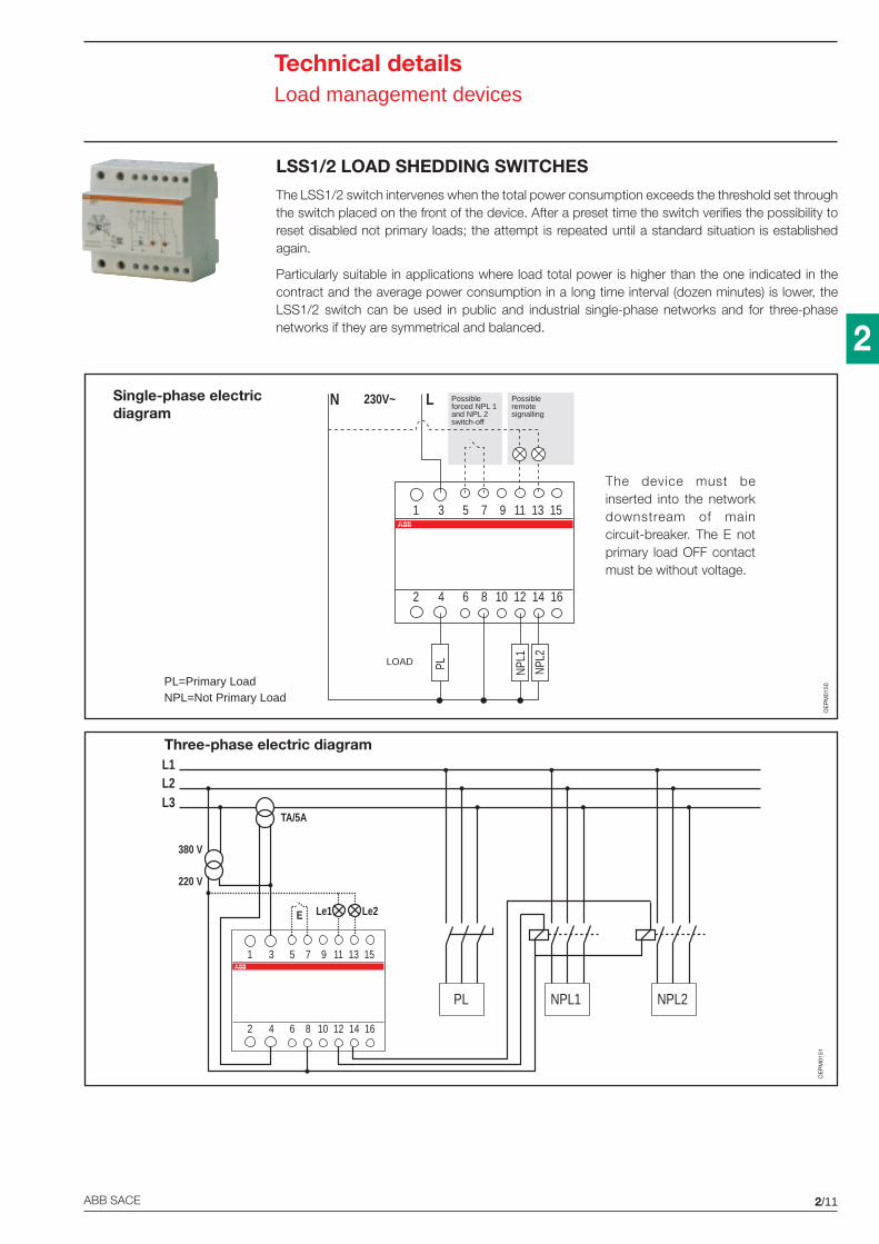
2/11ABB SACE
2
Technical detailsLoad management devices
LSS1/2 LOAD SHEDDING SWITCHES
The LSS1/2 switch intervenes when the total power consumption exceeds the threshold set throughthe switch placed on the front of the device. After a preset time the switch verifies the possibility toreset disabled not primary loads; the attempt is repeated until a standard situation is establishedagain.
Particularly suitable in applications where load total power is higher than the one indicated in thecontract and the average power consumption in a long time interval (dozen minutes) is lower, theLSS1/2 switch can be used in public and industrial single-phase networks and for three-phasenetworks if they are symmetrical and balanced.
LOAD
1 3 5 7 9 11 13 15
2 4 6 8 10 12 14 16
N L230V~
PL NPL1
NPL2
Possibleremotesignalling
Possibleforced NPL 1and NPL 2switch-off
Single-phase electricdiagram
The device must beinserted into the networkdownstream of maincircuit-breaker. The E notprimary load OFF contactmust be without voltage.
PL=Primary LoadNPL=Not Primary Load
1 3 5 7 9 11 13 15
2 4 6 8 10 12 14 16
L1
PL
L2L3
TA/5A
380 V
NPL1 NPL2
Le2Le1E
220 V
Three-phase electric diagram
OE
PM
0151
OE
PM
0150
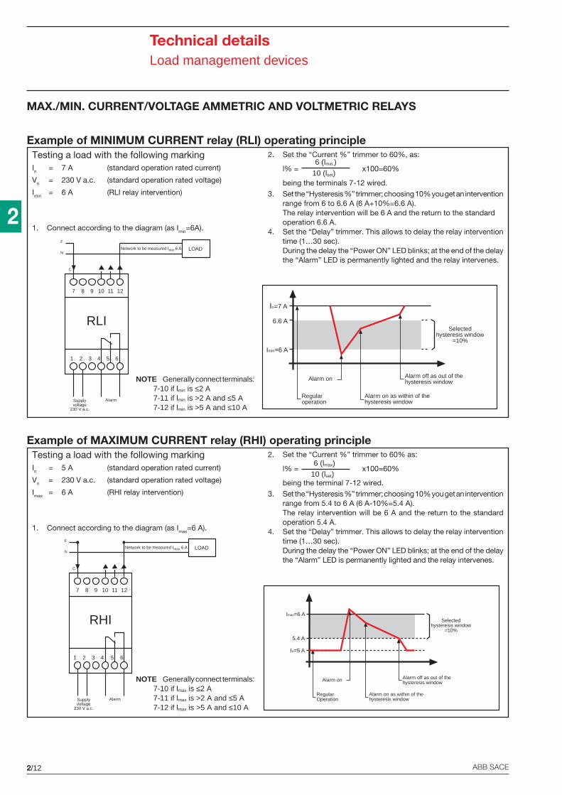
2/12 ABB SACE
2
Technical detailsLoad management devices
MAX./MIN. CURRENT/VOLTAGE AMMETRIC AND VOLTMETRIC RELAYS
Testing a load with the following markingIn = 7 A (standard operation rated current)
Vn = 230 V a.c. (standard operation rated voltage)
Imin = 6 A (RLI relay intervention)
1. Connect according to the diagram (as Imin=6A).
2. Set the “Current %” trimmer to 60%, as:
l% = x100=60%
being the terminals 7-12 wired.3. Set the “Hysteresis %” trimmer; choosing 10% you get an intervention
range from 6 to 6.6 A (6 A+10%=6.6 A).The relay intervention will be 6 A and the return to the standardoperation 6.6 A.
4. Set the “Delay” trimmer. This allows to delay the relay interventiontime (1…30 sec).During the delay the “Power ON” LED blinks; at the end of the delaythe “Alarm” LED is permanently lighted and the relay intervenes.
6 (lmin.)
10 (lset)
NOTE Generally connect terminals:7-10 if lmin is ≤2 A7-11 if lmin is >2 A and ≤5 A7-12 if lmin is >5 A and ≤10 A
Example of MINIMUM CURRENT relay (RLI) operating principle
Testing a load with the following markingIn = 5 A (standard operation rated current)
Vn = 230 V a.c. (standard operation rated voltage)
Imax = 6 A (RHI relay intervention)
1. Connect according to the diagram (as Imax=6 A).
2. Set the “Current %” trimmer to 60% as:
l% = x100=60%
being the terminal 7-12 wired.3. Set the “Hysteresis %” trimmer; choosing 10% you get an intervention
range from 5.4 to 6 A (6 A-10%=5.4 A).The relay intervention will be 6 A and the return to the standardoperation 5.4 A.
4. Set the “Delay” trimmer. This allows to delay the relay interventiontime (1…30 sec).During the delay the “Power ON” LED blinks; at the end of the delaythe “Alarm” LED is permanently lighted and the relay intervenes.
NOTE Generally connect terminals:7-10 if lmax is ≤2 A7-11 if lmax is >2 A and ≤5 A7-12 if lmax is >5 A and ≤10 A
Example of MAXIMUM CURRENT relay (RHI) operating principle
6 (lmax)
10 (lset)
In=7 A
6.6 A
Imin=6 A
Regularoperation
Alarm on
Alarm on as within of thehysteresis window
Alarm off as out of thehysteresis window
Selectedhysteresis window
=10%A
1 2 5 643
7 8 11 12109
AlarmSupplyvoltage
230 V a.c.
F
NLOAD
RLI
Network to be measured Imin 6 A
C
A
1 2 5 643
7 8 11 12109
AlarmSupplyvoltage
230 V a.c.
F
NLOAD
RHI
Network to be measured Imax 6 A
C
Imax=6 A
5.4 A
In=5 A
RegularOperation
Alarm on
Alarm on as within of thehysteresis window
Alarm off as out of thehysteresis window
Selectedhysteresis window
=10%
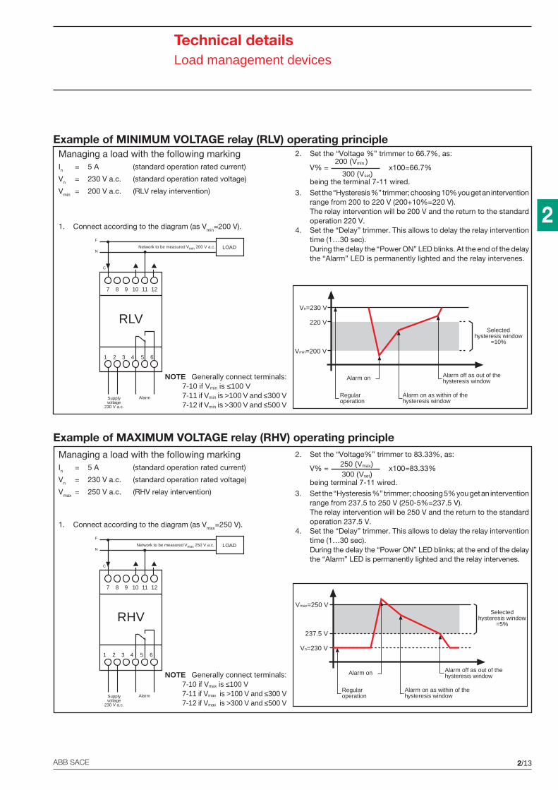
2/13ABB SACE
2
Technical detailsLoad management devices
Managing a load with the following markingIn = 5 A (standard operation rated current)
Vn = 230 V a.c. (standard operation rated voltage)
Vmin = 200 V a.c. (RLV relay intervention)
1. Connect according to the diagram (as Vmin=200 V).
2. Set the “Voltage %” trimmer to 66.7%, as:
V% = x100=66.7%
being the terminal 7-11 wired.3. Set the “Hysteresis %” trimmer; choosing 10% you get an intervention
range from 200 to 220 V (200+10%=220 V).The relay intervention will be 200 V and the return to the standardoperation 220 V.
4. Set the “Delay” trimmer. This allows to delay the relay interventiontime (1…30 sec).During the delay the “Power ON” LED blinks. At the end of the delaythe “Alarm” LED is permanently lighted and the relay intervenes.
200 (Vmin.)
300 (Vset)
NOTE Generally connect terminals:7-10 if Vmin is ≤100 V7-11 if Vmin is >100 V and ≤300 V7-12 if Vmin is >300 V and ≤500 V
Example of MINIMUM VOLTAGE relay (RLV) operating principle
A
1 2 5 643
7 8 11 12109
AlarmSupplyvoltage
230 V a.c.
F
NLOAD
RLV
Network to be measured Vmin 200 V a.c.
C
Vn=230 V
220 V
Vmin=200 V
Regularoperation
Alarm on
Alarm on as within of thehysteresis window
Alarm off as out of thehysteresis window
Selectedhysteresis window
=10%
Managing a load with the following markingIn = 5 A (standard operation rated current)
Vn = 230 V a.c. (standard operation rated voltage)
Vmax = 250 V a.c. (RHV relay intervention)
1. Connect according to the diagram (as Vmax=250 V).
2. Set the “Voltage%” trimmer to 83.33%, as:
V% = x100=83.33%
being terminal 7-11 wired.3. Set the “Hysteresis %” trimmer; choosing 5% you get an intervention
range from 237.5 to 250 V (250-5%=237.5 V).The relay intervention will be 250 V and the return to the standardoperation 237.5 V.
4. Set the “Delay” trimmer. This allows to delay the relay interventiontime (1…30 sec).During the delay the “Power ON” LED blinks; at the end of the delaythe “Alarm” LED is permanently lighted and the relay intervenes.
250 (Vmax)300 (Vset)
NOTE Generally connect terminals:7-10 if Vmax is ≤100 V7-11 if Vmax is >100 V and ≤300 V7-12 if Vmax is >300 V and ≤500 V
Example of MAXIMUM VOLTAGE relay (RHV) operating principle
A
1 2 5 643
7 8 11 12109
AlarmSupplyvoltage
230 V a.c.
F
NLOAD
RHV
Network to be measured Vmax 250 V a.c.
C
Vmax=250 V
237.5 V
Vn=230 V
Regularoperation
Alarm on
Alarm on as within of thehysteresis window
Alarm off as out of thehysteresis window
Selectedhysteresis window
=5%
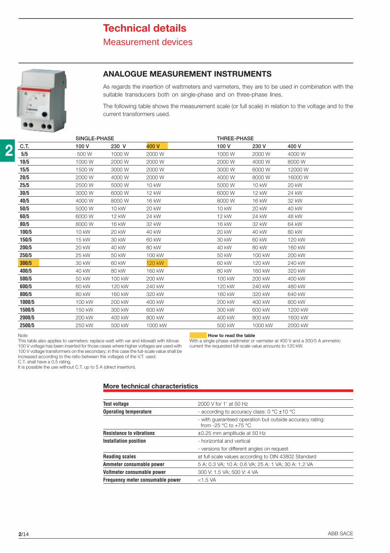
2/14 ABB SACE
2
Technical detailsMeasurement devices
ANALOGUE MEASUREMENT INSTRUMENTS
As regards the insertion of wattmeters and varmeters, they are to be used in combination with thesuitable transducers both on single-phase and on three-phase lines.
The following table shows the measurement scale (or full scale) in relation to the voltage and to thecurrent transformers used.
More technical characteristics
Test voltage 2000 V for 1’ at 50 Hz
Operating temperature - according to accuracy class: 0 °C ±10 °C- with guaranteed operation but outside accuracy rating: from -25 °C to +75 °C
Resistance to vibrations ±0.25 mm amplitude at 50 Hz
Installation position - horizontal and vertical
- versions for different angles on request
Reading scales at full scale values according to DIN 43802 Standard
Ammeter consumable power 5 A: 0.3 VA; 10 A: 0.6 VA; 25 A: 1 VA; 30 A: 1.2 VA
Voltmeter consumable power 300 V: 1.5 VA; 500 V: 4 VA
Frequency meter consumable power <1.5 VA
SINGLE-PHASE THREE-PHASE
C.T. 100 V 230 V 400 V 100 V 230 V 400 V
5/5 500 W 1000 W 2000 W 1000 W 2000 W 4000 W
10/5 1000 W 2000 W 2000 W 2000 W 4000 W 8000 W
15/5 1500 W 3000 W 2000 W 3000 W 6000 W 12000 W
20/5 2000 W 4000 W 2000 W 4000 W 8000 W 16000 W
25/5 2500 W 5000 W 10 kW 5000 W 10 kW 20 kW
30/5 3000 W 6000 W 12 kW 6000 W 12 kW 24 kW
40/5 4000 W 8000 W 16 kW 8000 W 16 kW 32 kW
50/5 5000 W 10 kW 20 kW 10 kW 20 kW 40 kW
60/5 6000 W 12 kW 24 kW 12 kW 24 kW 48 kW
80/5 8000 W 16 kW 32 kW 16 kW 32 kW 64 kW
100/5 10 kW 20 kW 40 kW 20 kW 40 kW 80 kW
150/5 15 kW 30 kW 60 kW 30 kW 60 kW 120 kW
200/5 20 kW 40 kW 80 kW 40 kW 80 kW 160 kW
250/5 25 kW 50 kW 100 kW 50 kW 100 kW 200 kW
300/5 30 kW 60 kW 120 kW 60 kW 120 kW 240 kW
400/5 40 kW 80 kW 160 kW 80 kW 160 kW 320 kW
500/5 50 kW 100 kW 200 kW 100 kW 200 kW 400 kW
600/5 60 kW 120 kW 240 kW 120 kW 240 kW 480 kW
800/5 80 kW 160 kW 320 kW 160 kW 320 kW 640 kW
1000/5 100 kW 200 kW 400 kW 200 kW 400 kW 800 kW
1500/5 150 kW 300 kW 600 kW 300 kW 600 kW 1200 kW
2000/5 200 kW 400 kW 800 kW 400 kW 800 kW 1600 kW
2500/5 250 kW 500 kW 1000 kW 500 kW 1000 kW 2000 kW
How to read the tableWith a single-phase wattmeter or varmeter at 400 V and a 300/5 A ammetriccurrent the requested full-scale value amounts to 120 kW.
NoteThis table also applies to varmeters: replace watt with var and kilowatt with kilovar.100 V voltage has been inserted for those cases where higher voltages are used with100 V voltage transformers on the secondary; in this case the full-scale value shall beincreased according to the ratio between the voltages of the V.T. used.C.T. shall have a 0.5 rating.It is possible the use without C.T. up to 5 A (direct insertion).
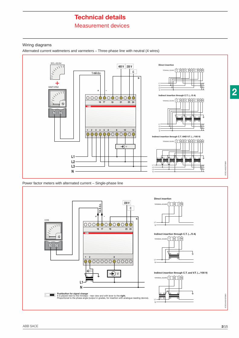
2/15ABB SACE
2
Technical detailsMeasurement devices
Alternated current wattmeters and varmeters – Three-phase line with neutral (4 wires)
Power factor meters with alternated current – Single-phase line
Indirect insertion through C.T. (.../5 A)
L1L2L3N
S1 S2
P1 P2
S1 S2
P1 P2
S1 S2
P1 P2
1 8 2 3 10 4 5 12 6 19TERMINAL BOARD
Indirect insertion through C.T. AND V.T. (.../100 V)
P1 P2 P1 P2
S1 S2 S1 S2
P1 P2
S1 S2S1 S2
P1 P2
S1 S2
P1 P2
S1 S2
P1 P2
L1L2L3N
1 8 2 3 10 4 5 12 6 19TERMINAL BOARD
Direct insertion
L1L2L3N
TERMINAL BOARD 1 8 2 3 10 4 5 12 6 19
L2L1
16 17 21 23 24
1 mA d.c.
+ -
400 V
C
L3
19
N
N
1 2 3 4 5 6 8 10 12
V
+
SCL-A3/A4
0
WMT/VRM
230 V
Indirect insertion through C.T. and V.T. (.../100 V)
S1 S2
P1 P21
N
S1
P1
S2
P2
8 2 191TERMINAL BOARD
L
Indirect insertion through C.T. (.../5 A)
S1 S2
P1 P21
N
8 2 191TERMINAL BOARD
L
Direct insertion
1
N
TERMINAL BOARD
L
8 2 191
Pushbutton for signal changeIt is placed next to the minidips – rear view and with lever to the right.Proportional to the phase angle (output in grades, for insertion with analogue reading device).
+
COS
1 2 8
P1 P2
S1 S2
5 A
NL1
16 17 23 24
+ -
19
N
230 V
C
1m A
d.c
.
0
V
2CS
C44
5037
F09
012C
SC
4450
15F
0901
Wiring diagrams
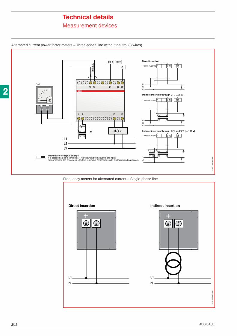
2/16 ABB SACE
2
Technical detailsMeasurement devices
Alternated current power factor meters – Three-phase line without neutral (3 wires)
Frequency meters for alternated current – Single-phase line
L3
V
1 2 10 12
P1 P2
S1 S2
5 A
L2L1
1716 21 23 24
400 V 230 V
C
+ -
1m A
d.c
.
+
0
COS
Direct insertion
L1L2L3
TERMINAL BOARD 2 10 121
Indirect insertion through C.T. (.../5 A)
S1 S2
P1 P2L1L2L3
TERMINAL BOARD 2 10 121
Indirect insertion through C.T. and V.T. (.../100 V)
S1 S2
P1 P2123
S1 S2
P1 P2
2 10 121TERMINAL BOARD
LLL
Pushbutton for signal changeIt is placed next to the minidips – rear view and with lever to the right.Proportional to the phase angle (output in grades, for insertion with analogue reading device).
Indirect insertion
L1
N
Direct insertion
L1
N
2CS
C44
5016
F09
012C
SC
4450
26F
0901
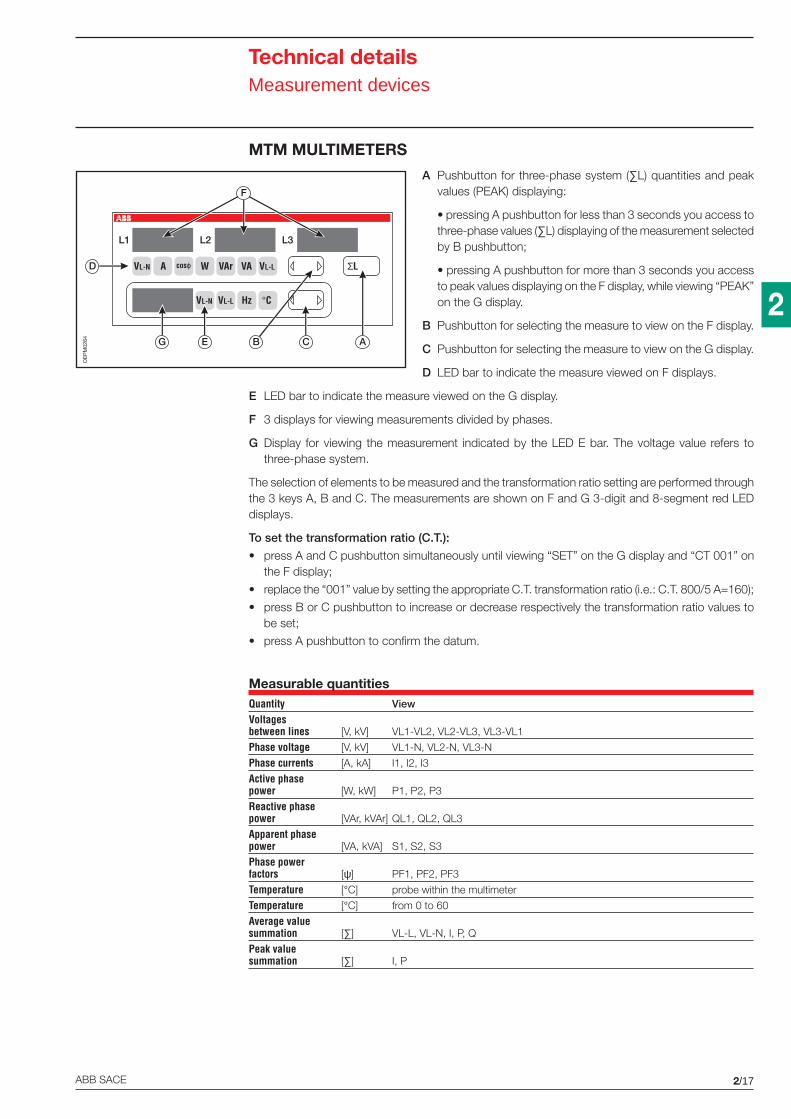
2/17ABB SACE
2
Technical detailsMeasurement devices
MTM MULTIMETERS
A Pushbutton for three-phase system (∑L) quantities and peakvalues (PEAK) displaying:
• pressing A pushbutton for less than 3 seconds you access tothree-phase values (∑L) displaying of the measurement selectedby B pushbutton;
• pressing A pushbutton for more than 3 seconds you accessto peak values displaying on the F display, while viewing “PEAK”on the G display.
B Pushbutton for selecting the measure to view on the F display.
C Pushbutton for selecting the measure to view on the G display.
D LED bar to indicate the measure viewed on F displays.
E LED bar to indicate the measure viewed on the G display.
F 3 displays for viewing measurements divided by phases.
G Display for viewing the measurement indicated by the LED E bar. The voltage value refers tothree-phase system.
The selection of elements to be measured and the transformation ratio setting are performed throughthe 3 keys A, B and C. The measurements are shown on F and G 3-digit and 8-segment red LEDdisplays.
To set the transformation ratio (C.T.):
• press A and C pushbutton simultaneously until viewing “SET” on the G display and “CT 001” onthe F display;
• replace the “001” value by setting the appropriate C.T. transformation ratio (i.e.: C.T. 800/5 A=160);
• press B or C pushbutton to increase or decrease respectively the transformation ratio values tobe set;
• press A pushbutton to confirm the datum.
Measurable quantitiesQuantity View
Voltagesbetween lines [V, kV] VL1-VL2, VL2-VL3, VL3-VL1
Phase voltage [V, kV] VL1-N, VL2-N, VL3-N
Phase currents [A, kA] I1, I2, I3
Active phasepower [W, kW] P1, P2, P3
Reactive phasepower [VAr, kVAr] QL1, QL2, QL3
Apparent phasepower [VA, kVA] S1, S2, S3
Phase powerfactors [ψ] PF1, PF2, PF3
Temperature [°C] probe within the multimeter
Temperature [°C] from 0 to 60
Average valuesummation [∑] VL-L, VL-N, I, P, Q
Peak valuesummation [∑] I, P
D
F
G E C AB
L1 L2 L3
VL-N A cosϕ W VAr VA VL-L
VL-N VL-L Hz °C
ΣL
OE
PM
0264
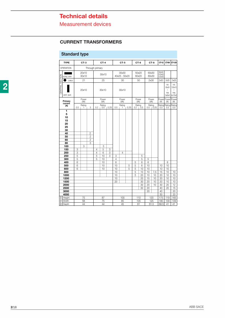
2/18 ABB SACE
2
Technical detailsMeasurement devices
CURRENT TRANSFORMERS
Standard type
TYPE
Power(VA)
Rating0.2 0.5 0.2S
30x10
25
5
20x1030x10
30x10
OPERATION
CE
NTR
AL
SE
CTI
ON
15
101520253040506080
100150200250300400500600800
1000120015002000250030004000
21
20x10
HORIZ. BAR
VERT. BAR
CABLE
Primarycurrent
(A)
Power(VA)
Rating0.5 1 3
30x3040x25 - 50x20
50x2060x20
CT-3 CT-12 CT-8V CT-12V
30 50
30x10
Power(VA)
Power(VA)
Rating0.5 1 0.2S
Rating0.2 0.5
60x3080x30
2x30
Power(VA)
Rating0.5 0.2S
2
3
4
10 106
10 1015 10 1020 10 1020 10 1020 10 1030 20 1240 20 1540 2050 20175 119 165180 109 10968.5 41 41
556101010 7,510 1015 1020 1020 102020
55 65 65 105 105 20
20303030
34610 510 510101020
4 5 34 6 35 10 35 10
101010
223
333
5666
755844
877544
100 11010561
12012561.5
8545DI
MEN
SIO
NS HeightWidthDepth
Power(VA)
Power(VA)
Power(VA)
Rating0.5
Rating0.5
Rating0.5
Through primary
80x50100x50125x50
2x50 2x35 3x35
min.80x30
÷max.
3x80x5
min.100x10
÷max.
4x125x5
CT-4 CT-5 CT-6 CT-8
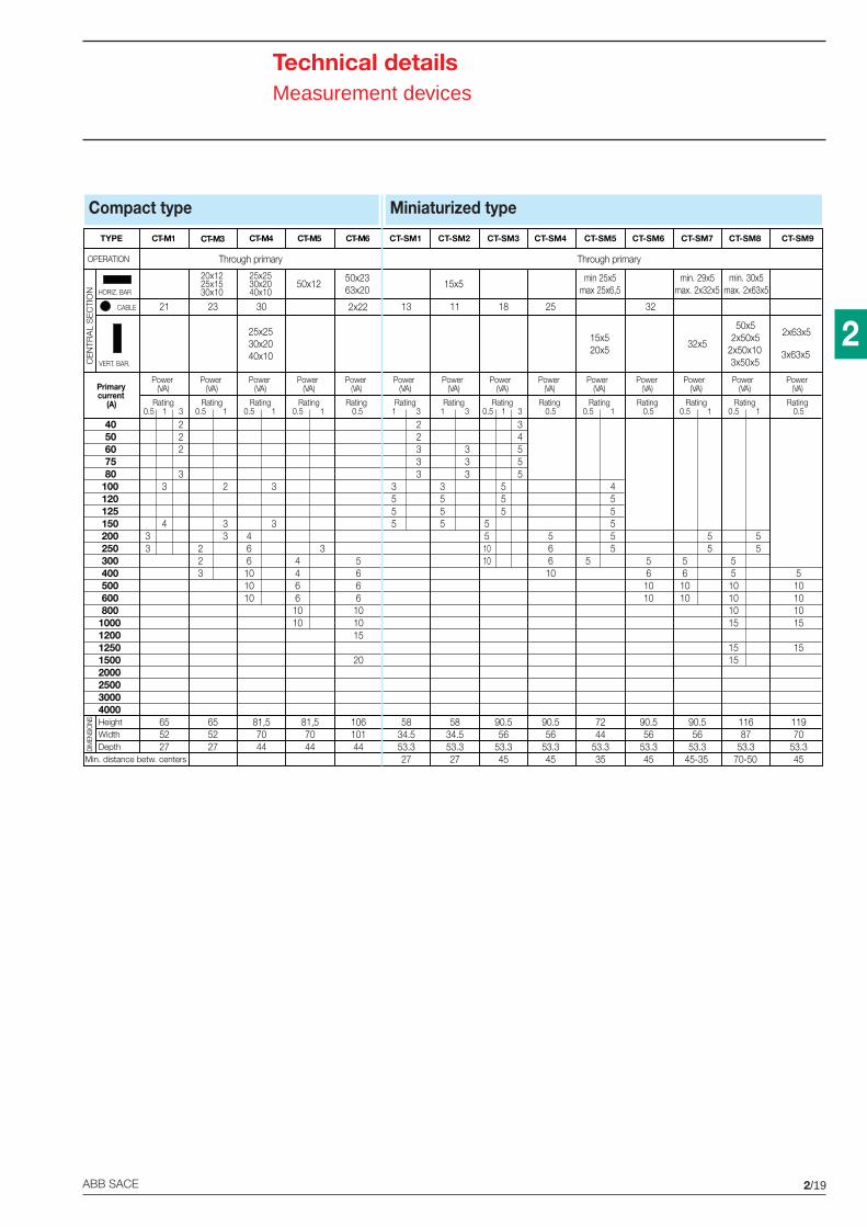
2/19ABB SACE
2
Technical detailsMeasurement devices
Power(VA)
Rating1 3
5834.553.327
13
CT-SM1
22333
3555
55
5
CT-SM3
18
Power(VA)
Rating0.5 1 3
3455
5551010
90.556
53.345
DIM
ENSI
ONS
TYPE
OPERATION
CT-M1
CE
NTR
AL
SE
CTI
ON
4050607580
100120125150200250300400500600800
10001200125015002000250030004000
21
HORIZ. BAR
VERT. BAR.
CABLE
Primarycurrent
(A)
Power(VA)
Rating0.5 1 3
20x1225x1530x10
25x2530x2040x10
50x1250x2363x20
CT-M3 CT-M4 CT-M5 CT-M6
23 30
25x2530x2040x10
Power(VA)
Rating0.5 1
Power(VA)
Power(VA)
Power(VA)
Rating0.5 1
Rating0.5 1
Rating0.5
222
33 2 3
346 3
5666
101015
20
4466
1010
6101010
33
223
65 81,552 7027 44
81,57044
10610144
433
655227
HeightWidthDepth
Min. distance betw. centers
Through primary
Miniaturized type
55
CT-SM4 CT-SM5 CT-SM6 CT-SM7 CT-SM9
25
min 25x5max 25x6,5
min. 29x5max. 2x32x5
min. 30x5max. 2x63x5
15x520x5
32x5
50x52x50x5
2x50x103x50x5
2x63x5
3x63x5
Power(VA)
Power(VA)
Power(VA)
Power(VA)
Power(VA)
Power(VA)
Power(VA)
Rating0.5 1
Rating0.5
Rating0.5
Rating0.5 1
Rating0.5 1
Rating0.5
Rating1 3
90.556
53.345
90.556
53.345
5834.553.327
7244
53.335
90.556
53.345-35
11687
53.370-50
11970
53.345
561010
6610
Through primary
11
15x5
CT-SM2
333
3555
4
5 55
5510101015
1515
5561010
555
55
510101015
15
Compact type
2x22
CT-SM8
32
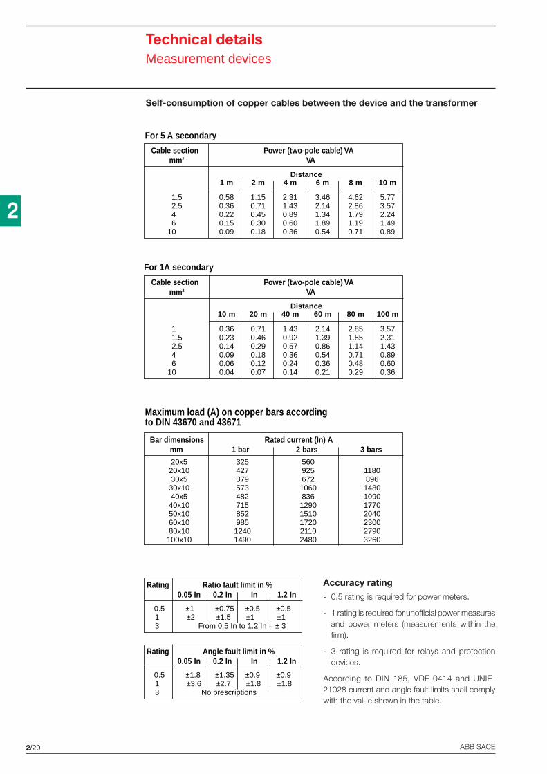
2/20 ABB SACE
2
20x5 325 56020x10 427 925 118030x5 379 672 89630x10 573 1060 148040x5 482 836 109040x10 715 1290 177050x10 852 1510 204060x10 985 1720 230080x10 1240 2110 2790100x10 1490 2480 3260
Bar dimensions Rated current (In) Amm 1 bar 2 bars 3 bars
Maximum load (A) on copper bars accordingto DIN 43670 and 43671
11.52.546
10
Distance10 m 20 m 40 m 60 m 80 m 100 m
0.36 0.71 1.43 2.14 2.85 3.570.23 0.46 0.92 1.39 1.85 2.310.14 0.29 0.57 0.86 1.14 1.430.09 0.18 0.36 0.54 0.71 0.890.06 0.12 0.24 0.36 0.48 0.600.04 0.07 0.14 0.21 0.29 0.36
Cable section Power (two-pole cable) VAmm2 VA
For 1A secondary
1.52.546
10
Distance1 m 2 m 4 m 6 m 8 m 10 m
0.58 1.15 2.31 3.46 4.62 5.770.36 0.71 1.43 2.14 2.86 3.570.22 0.45 0.89 1.34 1.79 2.240.15 0.30 0.60 1.89 1.19 1.490.09 0.18 0.36 0.54 0.71 0.89
Cable section Power (two-pole cable) VAmm2 VA
For 5 A secondary
Rating Angle fault limit in %0.05 In 0.2 In In 1.2 In
0.5 ±1.8 ±1.35 ±0.9 ±0.91 ±3.6 ±2.7 ±1.8 ±1.83 No prescriptions
Rating Ratio fault limit in %0.05 In 0.2 In In 1.2 In
0.5 ±1 ±0.75 ±0.5 ±0.51 ±2 ±1.5 ±1 ±13 From 0.5 In to 1.2 In = ± 3
Self-consumption of copper cables between the device and the transformer
Accuracy rating- 0.5 rating is required for power meters.
- 1 rating is required for unofficial power measuresand power meters (measurements within thefirm).
- 3 rating is required for relays and protectiondevices.
According to DIN 185, VDE-0414 and UNIE-21028 current and angle fault limits shall complywith the value shown in the table.
Technical detailsMeasurement devices
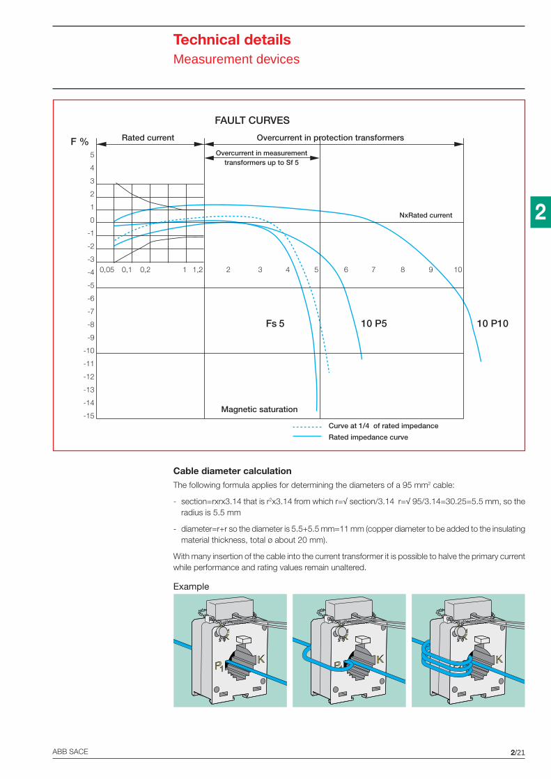
2/21ABB SACE
2
Technical detailsMeasurement devices
5
4
3
2
1
0
-1
-2
-3
-4
-5
-6
-7
-8
-9
-10
-11
-12
-13
-14
-15
F % Rated current Overcurrent in protection transformers
Overcurrent in measurementtransformers up to Sf 5
NxRated current
0,05 0,1 0,2 1 1,2 2 3 4 5 6 7 8 9 10
Fs 5 10 P5 10 P10
Magnetic saturation
Curve at 1/4 of rated impedance
Rated impedance curve
FAULT CURVES
Cable diameter calculationThe following formula applies for determining the diameters of a 95 mm2 cable:
- section=rxrx3.14 that is r2x3.14 from which r=√ section/3.14 r=√ 95/3.14=30.25=5.5 mm, so theradius is 5.5 mm
- diameter=r+r so the diameter is 5.5+5.5 mm=11 mm (copper diameter to be added to the insulatingmaterial thickness, total ø about 20 mm).
With many insertion of the cable into the current transformer it is possible to halve the primary currentwhile performance and rating values remain unaltered.
Example
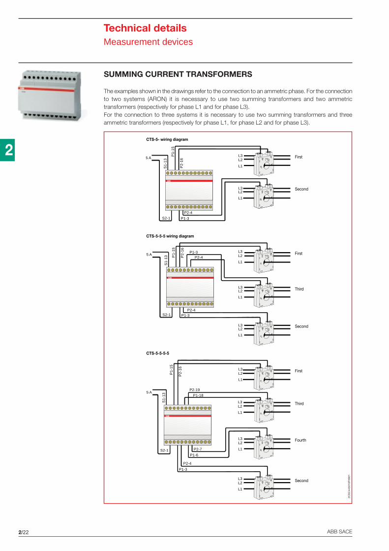
2/22 ABB SACE
2
CTS-5-5-5-5
S1-
13
5 A
P1-
15
P2-
16
P1-18
P2-19
P1-3
P2-4
P1-6
P2-7S2-1
L3
L1
L2
L3
L1
L2
L3
L1
L2
L3
L1
L2
CTS-5-5-5 wiring diagram
5 A
S1-
13 P1-
15
P2-
16
S2-1P2-4
P1-3
L3
L1
L2
L3
L1
L2
L3
L1
L2
P2-4P1-3
CTS-5- wiring diagram
L3
L1
L2
L3
L1
L2
5 A
S1-
13
P1-
15
P2-
16
S2-1
P2-4
P1-3
First
Second
First
Second
Third
First
Second
Third
Fourth
2CS
C44
5010
F09
01
SUMMING CURRENT TRANSFORMERS
The examples shown in the drawings refer to the connection to an ammetric phase. For the connectionto two systems (ARON) it is necessary to use two summing transformers and two ammetrictransformers (respectively for phase L1 and for phase L3).For the connection to three systems it is necessary to use two summing transformers and threeammetric transformers (respectively for phase L1, for phase L2 and for phase L3).
Technical detailsMeasurement devices
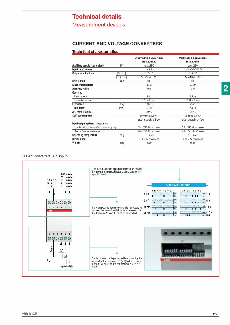
2/23ABB SACE
2
Technical detailsMeasurement devices
CURRENT AND VOLTAGE CONVERTERS
Technical characteristics
Ammetric converters Voltmetric convertersin a.c./d.c. in a.c./d.c.
Auxiliary supply (separated) [V] a.c. 230 a.c. 230Input rated values 1-5 A 120-300-500 VOutput rated values [V d.c.] 1-5-10 1-5-10
[mA d.c.] 1-5-10-4…20 1-5-10-4…20Ohmic load [mΩ] 700 700Measurement field 0±In 0±UnAccuracy rating 0.5 0.5Overload Permanent 2 In 2 Un Instantaneous 10 In/1 sec. 10 Un/1 sec.Frequency [Hz] 50/60 50/60Time delay [ms] ≤300 ≤300Alternated residue ≤1% ≤1%Self-consumption current ≤0,8 VA voltage ≤1 VA
aux. supply ≤4 VA aux. supply ≤4 VAInput/output galvanic separation Input/output insulation, aux. supply 2 kV/50 Hz -1 min 2 kV/50 Hz -1 min Circuit/mass insulation 4 kV/50 Hz -1 min 4 kV/50 Hz -1 minOperating temperature [°C] 0…+55 0…+55Dimensions 3-6 DIN modules 3-6 DIN modulesWeight [kg] 0.30 0.30
Current converters (a.c. input)
1 mA d.c.
7 8 9 10 11 12
10 V d.c.5 V d.c.1 V d.c.
+- +-
1 2 3 4 5 6
5 AMAX
C
1 AMAX
+
Supp
ly
Input signal (A)
4÷20 mA d.c.20 mA d.c.10 mA d.c.5 mA d.c.
The output selection must be performed by movingthe programming pushbuttons according to thespecific needs.
If a V output has been selected it is necessary toconnect terminals 7 and 8, while for mA outputsthe terminals 11 and 12 must be connected.
The input selection is performed by connecting theterminal of the common “C” (n. 6) to the terminal4, for a 1 A input, and to the terminal 5 for a 5 Ainput.
SELECTABLE OUTPUTS
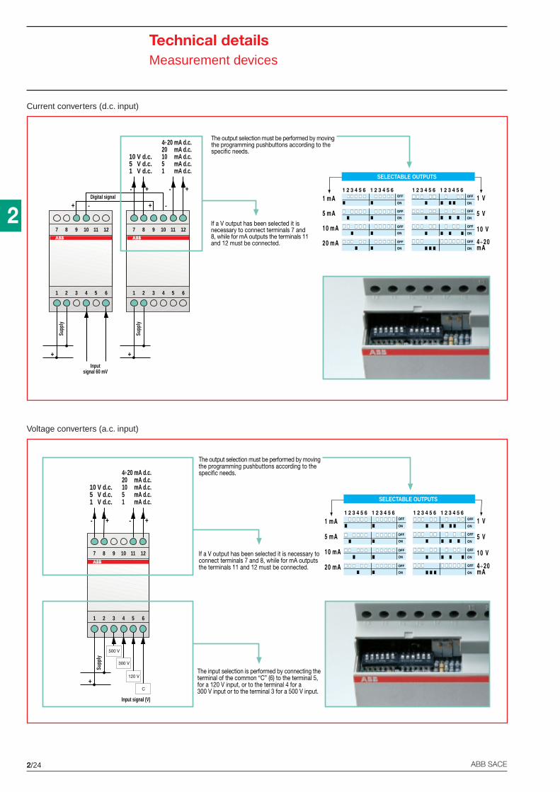
2/24 ABB SACE
2
Technical detailsMeasurement devices
Voltage converters (a.c. input)
Current converters (d.c. input)
Inputsignal 60 mV
7 8 9 10 11 12
+ -
1 2 3 4 5 6
+
Supp
ly
1 mA d.c.
7 8 9 10 11 12
10 V d.c.5 V d.c.1 V d.c.
+- +-
1 2 3 4 5 6
+
Supp
ly4÷20 mA d.c.20 mA d.c.10 mA d.c.5 mA d.c.
The output selection must be performed by movingthe programming pushbuttons according to thespecific needs.
If a V output has been selected it isnecessary to connect terminals 7 and8, while for mA outputs the terminals 11and 12 must be connected.
+ -Digital signal
SELECTABLE OUTPUTS
1 mA d.c.
7 8 9 10 11 12
10 V d.c.5 V d.c.1 V d.c.
+- +-
1 2 3 4 5 6
+
Supp
ly
Input signal (V)
4÷20 mA d.c.20 mA d.c.10 mA d.c.5 mA d.c.
The output selection must be performed by movingthe programming pushbuttons according to thespecific needs.
If a V output has been selected it is necessary toconnect terminals 7 and 8, while for mA outputsthe terminals 11 and 12 must be connected.
The input selection is performed by connecting theterminal of the common “C” (6) to the terminal 5,for a 120 V input, or to the terminal 4 for a300 V input or to the terminal 3 for a 500 V input.
120 V
300 V
500 V
C
SELECTABLE OUTPUTS
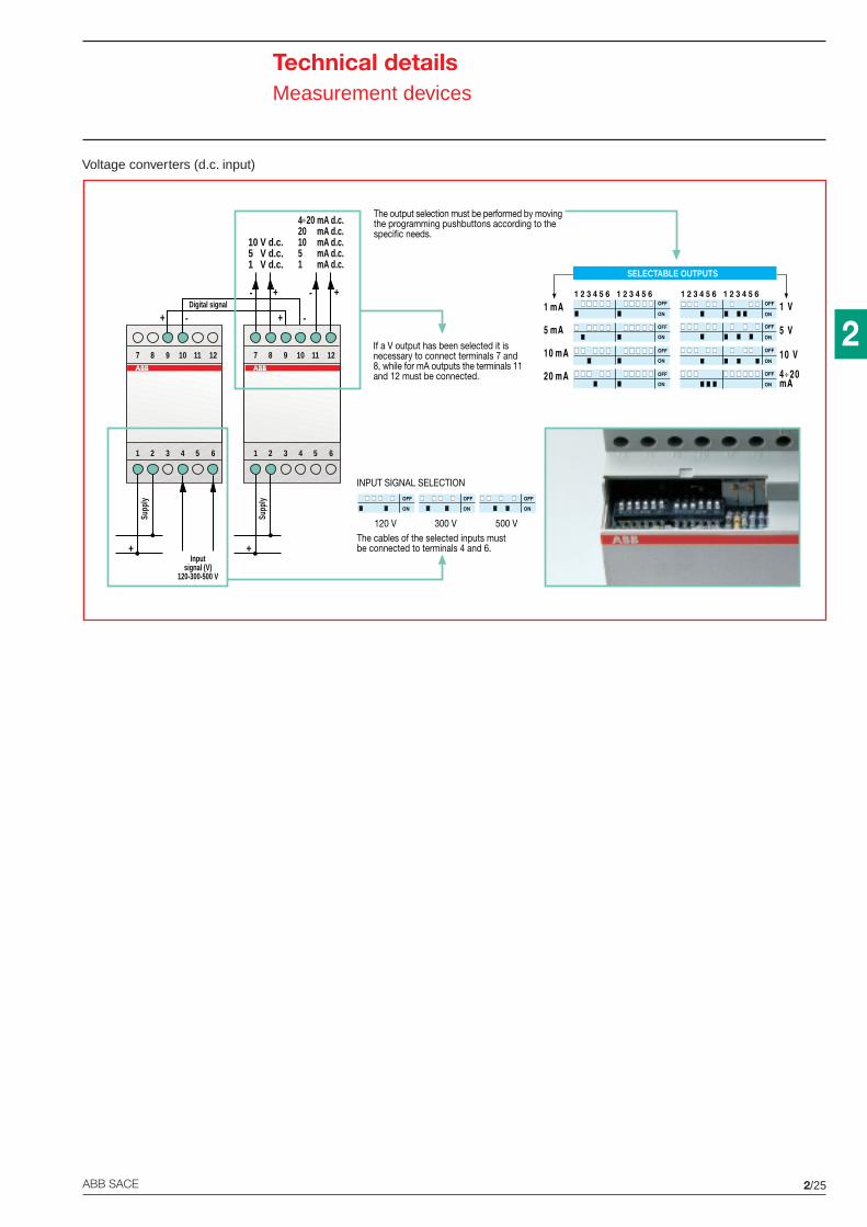
2/25ABB SACE
2
Technical detailsMeasurement devices
Voltage converters (d.c. input)
7 8 9 10 11 12
+ -
1 2 3 4 5 6
+
Supp
ly
Inputsignal (V)
120-300-500 V
1 mA d.c.
7 8 9 10 11 12
10 V d.c.5 V d.c.1 V d.c.
+- +-
1 2 3 4 5 6
+
Supp
ly
4÷20 mA d.c.20 mA d.c.10 mA d.c.5 mA d.c.
The output selection must be performed by movingthe programming pushbuttons according to thespecific needs.
If a V output has been selected it isnecessary to connect terminals 7 and8, while for mA outputs the terminals 11and 12 must be connected.
+ -Digital signal
The cables of the selected inputs mustbe connected to terminals 4 and 6.
INPUT SIGNAL SELECTION
120 V 300 V 500 V
SELECTABLE OUTPUTS
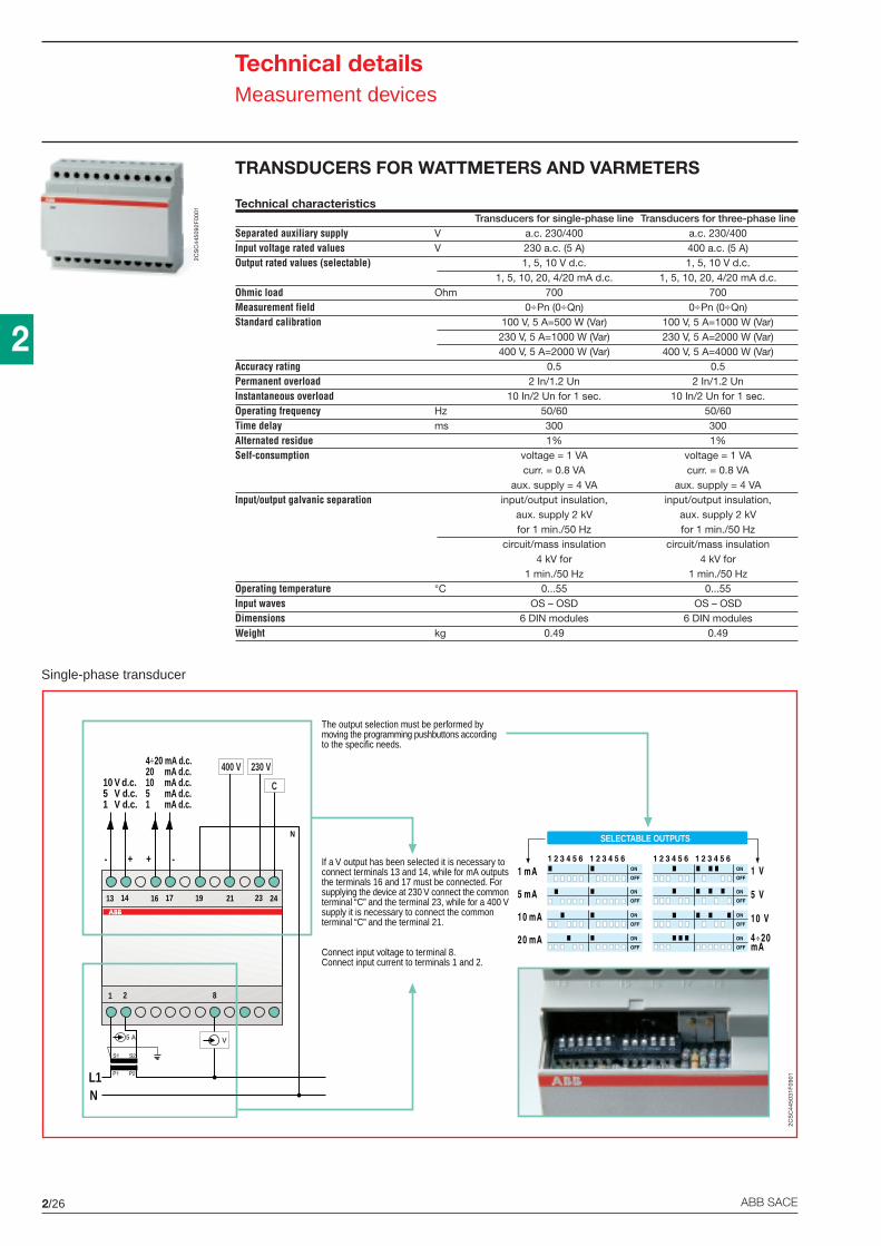
2/26 ABB SACE
2
Technical detailsMeasurement devices
TRANSDUCERS FOR WATTMETERS AND VARMETERS
Technical characteristicsTransducers for single-phase line Transducers for three-phase line
Separated auxiliary supply V a.c. 230/400 a.c. 230/400Input voltage rated values V 230 a.c. (5 A) 400 a.c. (5 A)Output rated values (selectable) 1, 5, 10 V d.c. 1, 5, 10 V d.c.
1, 5, 10, 20, 4/20 mA d.c. 1, 5, 10, 20, 4/20 mA d.c.Ohmic load Ohm 700 700Measurement field 0÷Pn (0÷Qn) 0÷Pn (0÷Qn)Standard calibration 100 V, 5 A=500 W (Var) 100 V, 5 A=1000 W (Var)
230 V, 5 A=1000 W (Var) 230 V, 5 A=2000 W (Var)400 V, 5 A=2000 W (Var) 400 V, 5 A=4000 W (Var)
Accuracy rating 0.5 0.5Permanent overload 2 In/1.2 Un 2 In/1.2 UnInstantaneous overload 10 In/2 Un for 1 sec. 10 In/2 Un for 1 sec.Operating frequency Hz 50/60 50/60Time delay ms 300 300Alternated residue 1% 1%Self-consumption voltage = 1 VA voltage = 1 VA
curr. = 0.8 VA curr. = 0.8 VAaux. supply = 4 VA aux. supply = 4 VA
Input/output galvanic separation input/output insulation, input/output insulation,aux. supply 2 kV aux. supply 2 kVfor 1 min./50 Hz for 1 min./50 Hz
circuit/mass insulation circuit/mass insulation4 kV for 4 kV for
1 min./50 Hz 1 min./50 HzOperating temperature °C 0...55 0...55Input waves OS – OSD OS – OSDDimensions 6 DIN modules 6 DIN modulesWeight kg 0.49 0.49
The output selection must be performed bymoving the programming pushbuttons accordingto the specific needs.
If a V output has been selected it is necessary toconnect terminals 13 and 14, while for mA outputsthe terminals 16 and 17 must be connected. Forsupplying the device at 230 V connect the commonterminal “C” and the terminal 23, while for a 400 Vsupply it is necessary to connect the commonterminal “C” and the terminal 21.
Connect input voltage to terminal 8.Connect input current to terminals 1 and 2.
V
1 2 8
P1 P2
S1 S2
5 A
NL1
13 14 16 17 21 23 24
10 V d.c.5 V d.c.1 V d.c.
+-
4÷20 mA d.c.20 mA d.c.10 mA d.c.5 mA d.c.1 mA d.c.
+ -
19
N
400 V 230 V
C
SELECTABLE OUTPUTS
Single-phase transducer
2CS
C44
5092
F00
01
2CS
C44
5031
F09
01
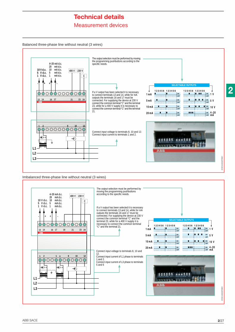
2/27ABB SACE
2
Technical detailsMeasurement devices
Balanced three-phase line without neutral (3 wires)
Imbalanced three-phase line without neutral (3 wires)
The output selection must be performed by movingthe programming pushbuttons according to thespecific needs.
If a V output has been selected it is necessaryto connect terminals 13 and 14, while for mAoutputs the terminals 16 and 17 must beconnected. For supplying the device at 230 Vconnect the common terminal “C” and the terminal23, while for a 400 V supply it is necessary toconnect the common terminal “C” and the terminal21.
Connect input voltage to terminals 8, 10 and 12.Connect input current to terminals 1 and 2.
1 2 8 10 12
P1 P2
S1 S2
5 A
L2L3
L1
10 V d.c.5 V d.c.1 V d.c.
+- + -
V
13 14 16 17 21 23 24
4÷20 mA d.c.20 mA d.c.10 mA d.c.5 mA d.c.1 mA d.c.
400 V 230 V
C
SELECTABLE OUTPUTS
Connect input voltage to terminals 8, 10 and12.Connect input current of L1 phase to terminals1 and 2.Connect input current of L3 phase to terminals5 and 6
The output selection must be performed bymoving the programming pushbuttonsaccording to the specific needs.
If a V output has been selected it is necessaryto connect terminals 13 and 14, while for mAoutputs the terminals 16 and 17 must beconnected. For supplying the device at 230 Vconnect the common terminal “C” and theterminal 23, while for a 400 V supply it isnecessary to connect the common terminal“C” and the terminal 21.
1 2 8 10 12
P1 P2
S1 S2
5 A
P1 P2
S1 S2
5 A
L2L3
L1
V
13 14 16 17 21 23 24
10 V d.c.5 V d.c.1 V d.c.
+-
4÷20 mA d.c.20 mA d.c.10 mA d.c.5 mA d.c.1 mA d.c.
+ -
19
400 V 230 V
C
5 6
SELECTABLE OUTPUTS2C
SC
4450
32F
0901
2CS
C44
5033
F09
01
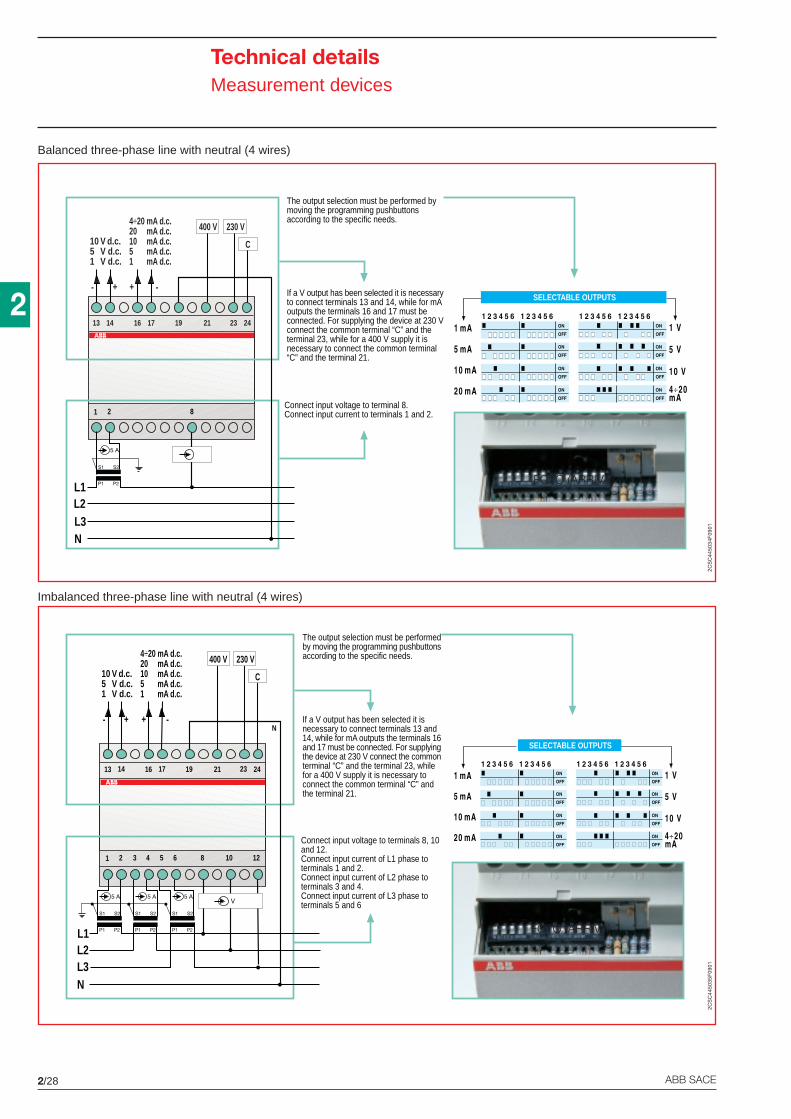
2/28 ABB SACE
2
Technical detailsMeasurement devices
Balanced three-phase line with neutral (4 wires)
Imbalanced three-phase line with neutral (4 wires)
The output selection must be performed bymoving the programming pushbuttonsaccording to the specific needs.
If a V output has been selected it is necessaryto connect terminals 13 and 14, while for mAoutputs the terminals 16 and 17 must beconnected. For supplying the device at 230 Vconnect the common terminal “C” and theterminal 23, while for a 400 V supply it isnecessary to connect the common terminal“C” and the terminal 21.
Connect input voltage to terminal 8.Connect input current to terminals 1 and 2.1 2 8
P1 P2
S1 S2
5 A
L2L3N
L1
V
13 14 16 17 21 23 24
10 V d.c.5 V d.c.1 V d.c.
+-
4÷20 mA d.c.20 mA d.c.10 mA d.c.5 mA d.c.1 mA d.c.
+ -
19
N
400 V 230 V
C
SELECTABLE OUTPUTS
The output selection must be performedby moving the programming pushbuttonsaccording to the specific needs.
If a V output has been selected it isnecessary to connect terminals 13 and14, while for mA outputs the terminals 16and 17 must be connected. For supplyingthe device at 230 V connect the commonterminal “C” and the terminal 23, whilefor a 400 V supply it is necessary toconnect the common terminal “C” andthe terminal 21.
Connect input voltage to terminals 8, 10and 12.Connect input current of L1 phase toterminals 1 and 2.Connect input current of L2 phase toterminals 3 and 4.Connect input current of L3 phase toterminals 5 and 6
1 2 3 4 5 6 8 10 12
V
P1 P2
S1 S2
P1 P2
S1 S2
5 A
P1 P2
S1 S2
5 A5 A
L2
NL3
L1
13 14 16 17 21 23 24
10 V d.c.5 V d.c.1 V d.c.
+-
4÷20 mA d.c.20 mA d.c.10 mA d.c.5 mA d.c.1 mA d.c.
+ -
19
N
400 V 230 V
C
SELECTABLE OUTPUTS
FOTO (ARRIVA)
FOTO (ARRIVA)
2CS
C44
5034
F09
012C
SC
4450
35F
0901
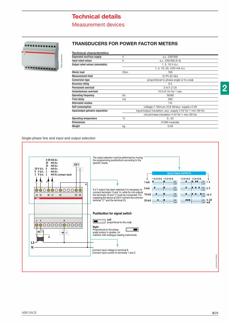
2/29ABB SACE
2
Technical detailsMeasurement devices
TRANSDUCERS FOR POWER FACTOR METERS
Technical characteristicsSeparated auxiliary supply V a.c. 230/400Input rated values V a.c. 230/400 (5 A)Output rated values (selectable) 1, 5, 10 V d.c.
1, 5, 10, 20, 4/20 mA d.c.Ohmic load Ohm 700Measurement field 0÷Pn (0÷Qn)Conversion type proportional to phase angle or to cosϕAccuracy rating 0.5Permanent overload 2 In/1.2 UnInstantaneous overload 10 In/2 Un for 1 sec.Operating frequency Hz 50/60Time delay ms 300Alternated residue 1%Self-consumption voltage=1 VA/curr.=0.8 VA/aux. supply=4 VAInput/output galvanic separation input/output insulation, aux. supply 2 kV for 1 min./50 Hz
circuit/mass insulation 4 kV for 1 min./50 HzOperating temperature °C 0...55Dimensions 6 DIN modulesWeight kg 0.49
The output selection must be performed by movingthe programming pushbuttons according to thespecific needs.
If a V output has been selected it is necessary toconnect terminals 13 and 14, while for mA outputsthe terminals 16 and 17 must be connected. Forsupplying the device at 230 V connect the commonterminal “C” and the terminal 23.
Pushbutton for signal switch
Leftproportional to the cosϕ.
RightProportional to the phaseangle (output in grades, forinsertion with analogue reading instrument).
Connect input voltage to terminal 8.Connect input current to terminals 1 and 2.
4÷20 mA d.c.20 mA d.c.10 mA d.c.5 mA d.c.1 mA d.c.1 mA d.c. (analogue signal)
V
1 2 8
P1 P2
S1 S2
5 A
NL1
13 23 2419
N
230 V
C
14 16 17
10 V d.c.5 V d.c.1 V d.c.
+- + -
SELECTABLE OUTPUTS
Single-phase line and input and output selection
2CS
C44
5093
F00
01
2CS
C44
5013
F09
01
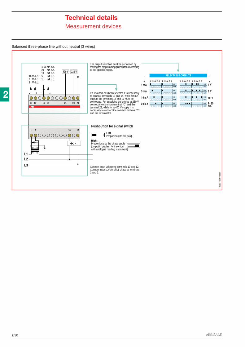
2/30 ABB SACE
2
Balanced three-phase line without neutral (3 wires)
V
1 2 10 12
P1 P2
S1 S2
5 A
L2
L3
L1
21 23 24
400 V 230 V
C
13 14 16 17
10 V d.c.5 V d.c.1 V d.c.
+- + -
4÷20 mA d.c.20 mA d.c.10 mA d.c.5 mA d.c.1 mA d.c.1 mA CC (segnale analogico)
Connect input voltage to terminals 10 and 12.Connect input current of L1 phase to terminals1 and 2.
The output selection must be performed bymoving the programming pushbuttons accordingto the specific needs.
If a V output has been selected it is necessaryto connect terminals 13 and 14, while for mAoutputs the terminals 16 and 17 must beconnected. For supplying the device at 230 Vconnect the common terminal “C” and theterminal 23, while for a 400 V supply it isnecessary to connect the common terminal “C”and the terminal 21.
Pushbutton for signal switch
LeftProportional to the cosϕ.
RightProportional to the phase angle(output in grades, for insertionwith analogue reading instrument).
SELECTABLE OUTPUTS
2CS
C44
5014
F09
01
Technical detailsMeasurement devices
2/31ABB SACE
2
Technical detailsMeasurement devices
INSULATION MONITORS
The insulation transformers provide protection from indirect contacts without breaking the circuit atthe first indirect contact. They are used mostly in systems where miniature circuit-breaking is notallowed because a sudden service breaking could cause serious inconveniences.
The Standards define strict safety rules; in particular, the active parts of the separate circuit must nothave shared parts, nor connections to earth. In addition, an appropriate device for the permanenttesting of the insulation status must be provided in order to detect, signal and remove the circuit firstfault.
Isoltester-CThis device operates generating a test voltage which is applied between the circuit leading to theinsulation transformer secondary and earth system. The current that is generated is made up by anIr (ohmic earth leakage) and an Ic (capacitive earth leakage) component. It closes between theinsulated system and the earth allowing to detect the leakage.
If passing through the sensing electronic device the ohmic/capacitive global leakage exceeds theone preset, the alarm is activated and the device yellow lighted indicator switches on.
The alarm status is then reported on the appropriate QSD acoustic/lighted signalling panel, that canbe placed remotely from the switchboard.
Selvtester-CDesigned according to an operating principle similar to Isolterster-C with which can be coupled, thisdevice signals the first indirect contact in SELV circuits shunted from insulated network with transformer(i.e. in systems for operating theatres where scialytic lamps are connected).
In addition to this insulation control basic function, Selvtester-C enables to view through green andyellow LED respectively the operating status and any indirect contact.
A specific pushbutton enables to perform periodic self-test operations.
QSD 230/24 C panels for remote signallingEach panel is equipped with a green indicator to signal the standard operation and with a yellowindicator reporting the alarms triggered by devices.
In case of alarm an appropriate acoustic signalling buzzer is also provided which can be switched offby switching the silencing relay (green pushbutton). The lighted signal is active until the cause of thealarm stops.
In order to perform periodic alarm test with simulation of indirect contact, press the red pushbutton.
The panels are provided along with the relative support, plate and flush-mounting box alreadyassembled.
2/32 ABB SACE
2
Technical detailsOther modular functions
TM/TS BELL TRANSFORMERS
The strict design criteria and the quality of materials used guarantee a high reliability of these devices.Windings are completely separated and insulated, so that the transfer of dangerous voltages on thesecondary is prevented even in the case of operation faults
Voltage values on the secondary with a rated load (according to IEC-EN 61558-2-8 Standard) candeviate by 15% from the rated value.
These safety transformers are available in 4 series.
- Failure-proof (TM series)
Following a possible anomalous use they do not operate any more, but they do not pose anydanger for the user or for adjacent electric parts: the series includes 8 models with 10, 15, 30 and40 VA power and 4, 8, 12 and 24 V output voltages.
- Short-circuit proof not by construction (TS8 series)
Even after a short-circuit they maintain the temperature below the specified limits and can operate;TS8 series includes 3 models with 8 VA power and output voltage of 8, 12, 24 V.
- Short-circuit proof not by construction (TS8/SW series)
Unlike the previous version this is equipped with an ON-OFF pushbutton on the frontal part thatallows the insertion or the disinsertion of the transformer in the line; TS8/SW series includes 4models with 8 VA power and output voltages of 4, 6, 8 and 12 V.
- Short-circuit proof not by construction (TS16/TS24 series)
Even after a short-circuit they maintain a temperature below the specified limits. Moreover they areequipped with a thermal cutoff device with automatic closing that automatically restores the currentwhen the relevant transformer part is cold enough or when the load has been removed; TS16/TS24series includes 7 models with power of 16 and 24 VA and output voltages of 4, 6, 8, 12 and 24 V.
3/1ABB SACE
3
Application sheets
Contents
E 259 installation relays .......................................................................................................... 3/4
E 250 latching relays .............................................................................................................. 3/5
ATS electro-mechanical time switches ................................................................................... 3/6
DTS digital time switches ....................................................................................................... 3/7
DTS-TWS twilight switches with built-in time switches ........................................................... 3/8
RAL overload alarms ............................................................................................................ 3/10
LSS1/2 load shedding switches ............................................................................................3/11
SQZ3 phase and sequence relays ........................................................................................ 3/12
Examples of applications
Residential buildings
Public buildings
Commercial buildings
Industry
Handicraft
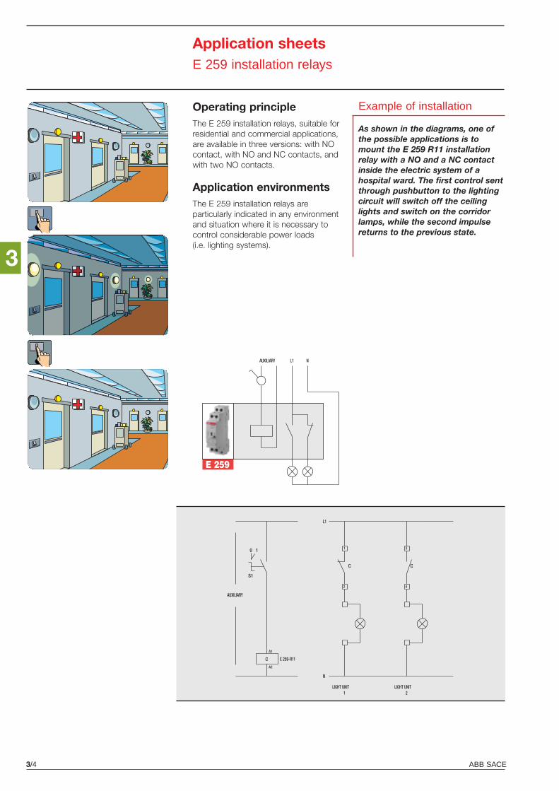
E 259
AUXILIARY L1 N
ABB SACE3/4
3
Application sheetsE 259 installation relays
Operating principleThe E 259 installation relays, suitable forresidential and commercial applications,are available in three versions: with NOcontact, with NO and NC contacts, andwith two NO contacts.
Application environmentsThe E 259 installation relays areparticularly indicated in any environmentand situation where it is necessary tocontrol considerable power loads(i.e. lighting systems).
Example of installation
As shown in the diagrams, one ofthe possible applications is tomount the E 259 R11 installationrelay with a NO and a NC contactinside the electric system of ahospital ward. The first control sentthrough pushbutton to the lightingcircuit will switch off the ceilinglights and switch on the corridorlamps, while the second impulsereturns to the previous state.
E 259-R11
1LIGHT UNIT
N
2
1
C
AUXILIARY
L1
4
3
C
A2
A1
S1
0 1
LIGHT UNIT2
C
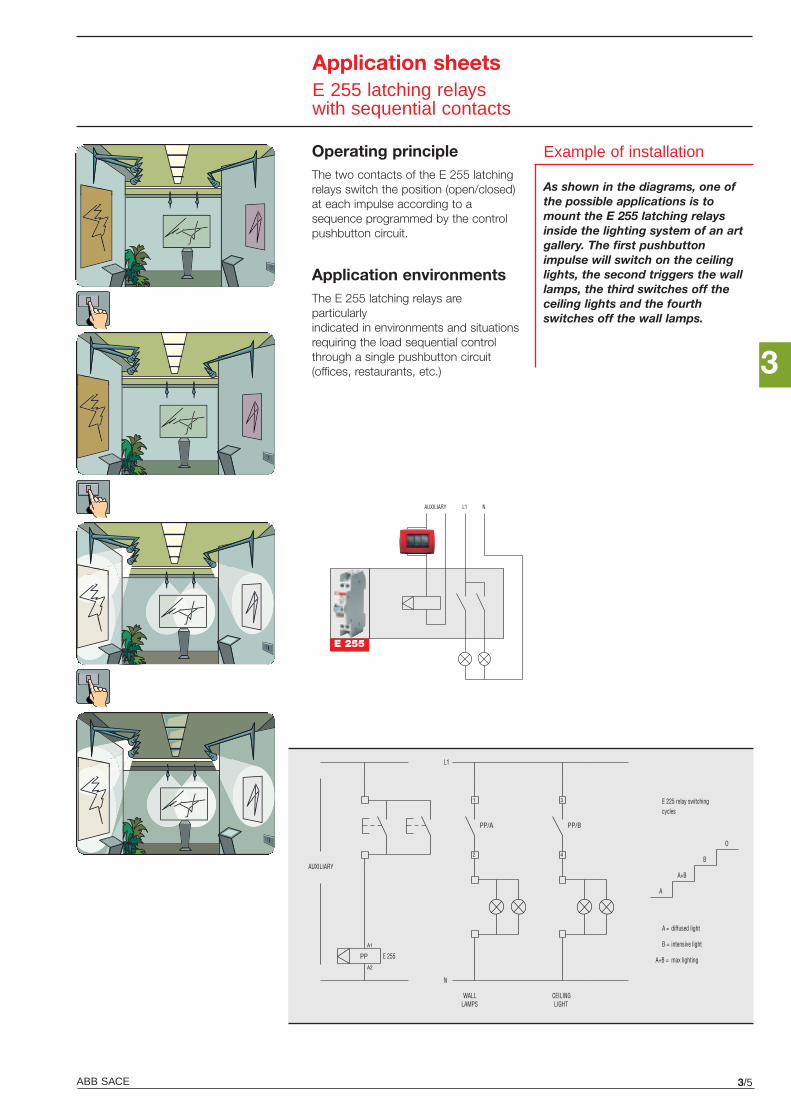
ABB SACE 3/5
3
Application sheetsE 255 latching relayswith sequential contacts
Operating principleThe two contacts of the E 255 latchingrelays switch the position (open/closed)at each impulse according to asequence programmed by the controlpushbutton circuit.
Application environmentsThe E 255 latching relays areparticularlyindicated in environments and situationsrequiring the load sequential controlthrough a single pushbutton circuit(offices, restaurants, etc.)
Example of installation
As shown in the diagrams, one ofthe possible applications is tomount the E 255 latching relaysinside the lighting system of an artgallery. The first pushbuttonimpulse will switch on the ceilinglights, the second triggers the walllamps, the third switches off theceiling lights and the fourthswitches off the wall lamps.
E255
L1 NAUXILIARY
A2
PP
A1
PP/A
2
1
PP/B
4
3
L1
N
AUXILIARY
WALL LAMPS LIGHT
CEILING
A
A+B
B
O
A = diffused light
B = intensive light
max lightingA+B =
E 225 relay switching cycles
E 255
E 255
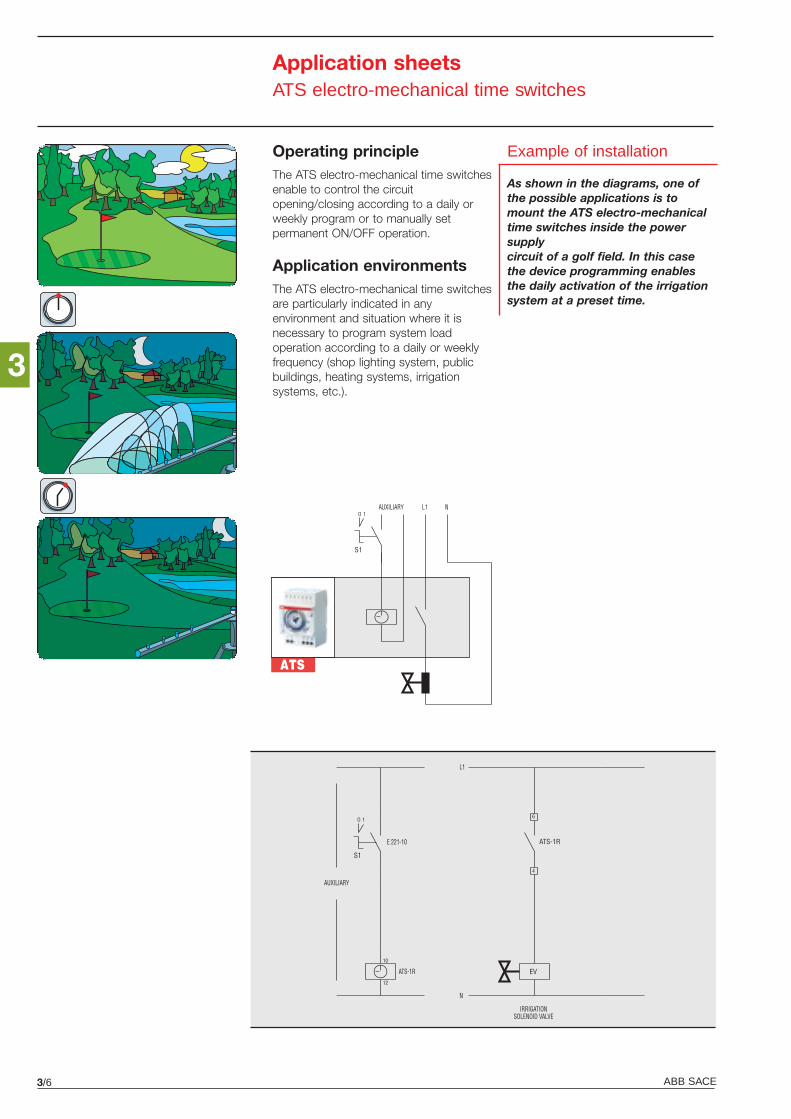
ABB SACE3/6
Application sheetsATS electro-mechanical time switches
Operating principleThe ATS electro-mechanical time switchesenable to control the circuitopening/closing according to a daily orweekly program or to manually setpermanent ON/OFF operation.
Application environmentsThe ATS electro-mechanical time switchesare particularly indicated in anyenvironment and situation where it isnecessary to program system loadoperation according to a daily or weeklyfrequency (shop lighting system, publicbuildings, heating systems, irrigationsystems, etc.).
Example of installation
As shown in the diagrams, one ofthe possible applications is tomount the ATS electro-mechanicaltime switches inside the powersupplycircuit of a golf field. In this casethe device programming enablesthe daily activation of the irrigationsystem at a preset time.
AUXILIARY L1 N
S1
1O
ATS
ATS-1R
IRRIGATIONSOLENOID VALVE
N
4
6
ATS-1R
AUXILIARY
L1
12
10
S1
1O
EV
E 221-10
3
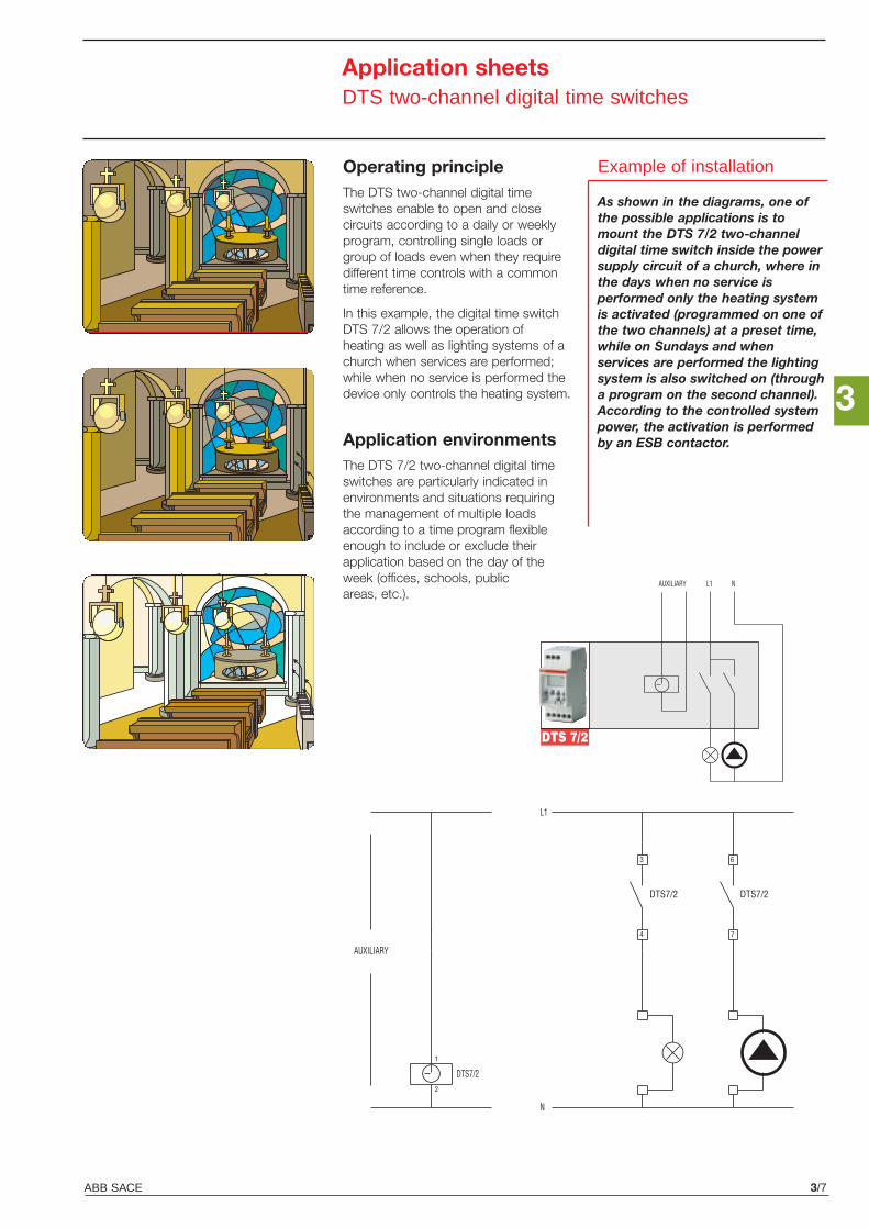
ABB SACE 3/7
Application sheetsDTS two-channel digital time switches
Operating principleThe DTS two-channel digital timeswitches enable to open and closecircuits according to a daily or weeklyprogram, controlling single loads orgroup of loads even when they requiredifferent time controls with a commontime reference.
In this example, the digital time switchDTS 7/2 allows the operation ofheating as well as lighting systems of achurch when services are performed;while when no service is performed thedevice only controls the heating system.
Application environmentsThe DTS 7/2 two-channel digital timeswitches are particularly indicated inenvironments and situations requiringthe management of multiple loadsaccording to a time program flexibleenough to include or exclude theirapplication based on the day of theweek (offices, schools, publicareas, etc.).
2
1
N
DTS7/2
DTS7/2
4
3
AUXILIARY
L1
7
6
DTS7/2
DTS 7/2
AUXILIARY L1 N
Example of installation
As shown in the diagrams, one ofthe possible applications is tomount the DTS 7/2 two-channeldigital time switch inside the powersupply circuit of a church, where inthe days when no service isperformed only the heating systemis activated (programmed on one ofthe two channels) at a preset time,while on Sundays and whenservices are performed the lightingsystem is also switched on (througha program on the second channel).According to the controlled systempower, the activation is performedby an ESB contactor.
3
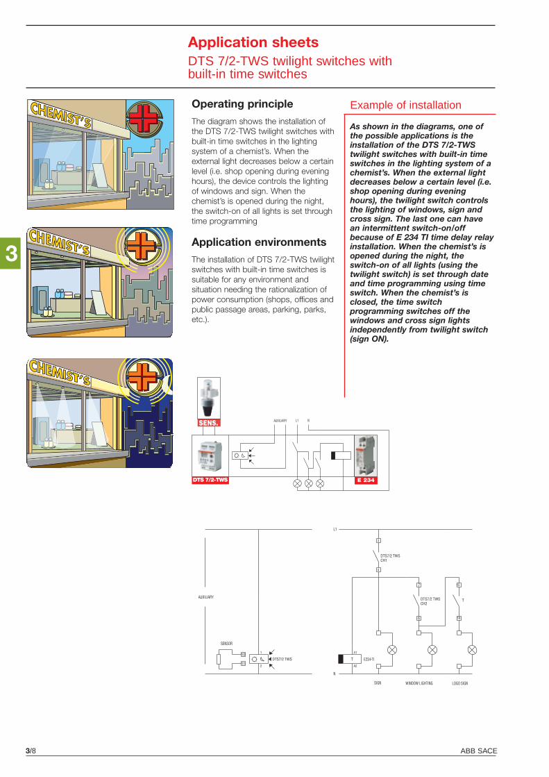
ABB SACE3/8
3
Application sheetsDTS 7/2-TWS twilight switches with built-in time switches
Operating principle
The diagram shows the installation ofthe DTS 7/2-TWS twilight switches withbuilt-in time switches in the lightingsystem of a chemist’s. When theexternal light decreases below a certainlevel (i.e. shop opening during eveninghours), the device controls the lightingof windows and sign. When thechemist’s is opened during the night,the switch-on of all lights is set throughtime programming
Application environments
The installation of DTS 7/2-TWS twilightswitches with built-in time switches issuitable for any environment andsituation needing the rationalization ofpower consumption (shops, offices andpublic passage areas, parking, parks,etc.).
10
11DTS7/2 TWS
DTS7/2 TWSCH1
7
6
DTS7/2 TWSCH2
AUXILIARY
SENSOR
SIGN WINDOW LIGHTING LOGO SIGN
DTS/TWS-2
AUXILIARY
Example of installation
As shown in the diagrams, one ofthe possible applications is theinstallation of the DTS 7/2-TWStwilight switches with built-in timeswitches in the lighting system of achemist’s. When the external lightdecreases below a certain level (i.e.shop opening during eveninghours), the twilight switch controlsthe lighting of windows, sign andcross sign. The last one can havean intermittent switch-on/offbecause of E 234 TI time delay relayinstallation. When the chemist’s isopened during the night, theswitch-on of all lights (using thetwilight switch) is set through dateand time programming using timeswitch. When the chemist’s isclosed, the time switchprogramming switches off thewindows and cross sign lightsindependently from twilight switch(sign ON).
DTS 7/2-TWS E 234
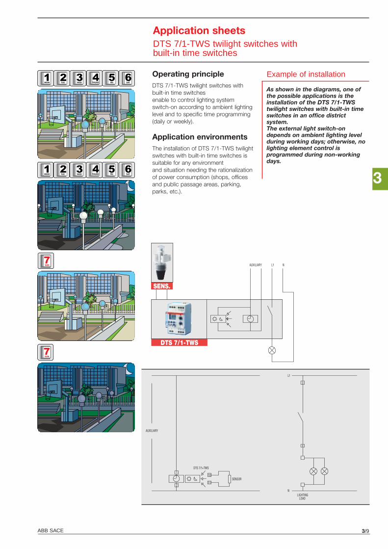
3
ABB SACE 3/9
Application sheetsDTS 7/1-TWS twilight switches with built-in time switches
MON
DTS 7/1-TWS
SENS.
AUXILIARY L1 N
DTS 7/1+TWS
AUXILIARY
LIGHTING LOAD
N
L1
10
3
4
11SENSOR
1
2
Operating principleDTS 7/1-TWS twilight switches withbuilt-in time switchesenable to control lighting systemswitch-on according to ambient lightinglevel and to specific time programming(daily or weekly).
Application environmentsThe installation of DTS 7/1-TWS twilightswitches with built-in time switches issuitable for any environmentand situation needing the rationalizationof power consumption (shops, officesand public passage areas, parking,parks, etc.).
Example of installation
As shown in the diagrams, one ofthe possible applications is theinstallation of the DTS 7/1-TWStwilight switches with built-in timeswitches in an office districtsystem.The external light switch-ondepends on ambient lighting levelduring working days; otherwise, nolighting element control isprogrammed during non-workingdays.
TUE WED THURS FRI SAT
MON TUE WED THURS FRI SAT
SUN
SUN
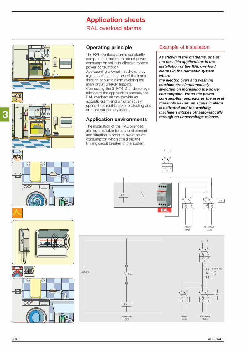
B.A.
AUXILIARY
LOADSPRIMARY NOT PRIMARY
LOADS
Id
N L1
B.A.
RAL
ABB SACE3/10
3
Application sheetsRAL overload alarms
Operating principleThe RAL overload alarms constantlycompare the maximum preset powerconsumption value to effective systempower consumption.Approaching allowed threshold, theysignal to disconnect one of the loadsthrough acoustic alarm avoiding themain circuit breaker tripping.Connecting the S 9-T415 undervoltagerelease to the appropriate contact, theRAL overload alarms provide anacoustic alarm and simultaneouslyopens the circuit-breaker protecting oneor more not primary loads.
Application environmentsThe installation of the RAL overloadalarms is suitable for any environmentand situation in order to avoid powerconsumption which could trip thelimiting circuit breaker of the system.
Example of installation
As shown in the diagrams, one ofthe possible applications is theinstallation of the RAL overloadalarms in the domestic systemwherethe electric oven and washingmachine are simultaneouslyswitched on increasing the powerconsumption. When the powerconsumption approaches the presetthreshold values, an acoustic alarmis activated and the washingmachine switches off automaticallythrough an undervoltage release.
3
1
B.A.
LOADS
AUXILIARY
NL1
Id
NOT PRIMARY PRIMARYLOADS
RAL
BUILT-IN BELL
B.A.
RAL
LOADSNOT PRIMARY
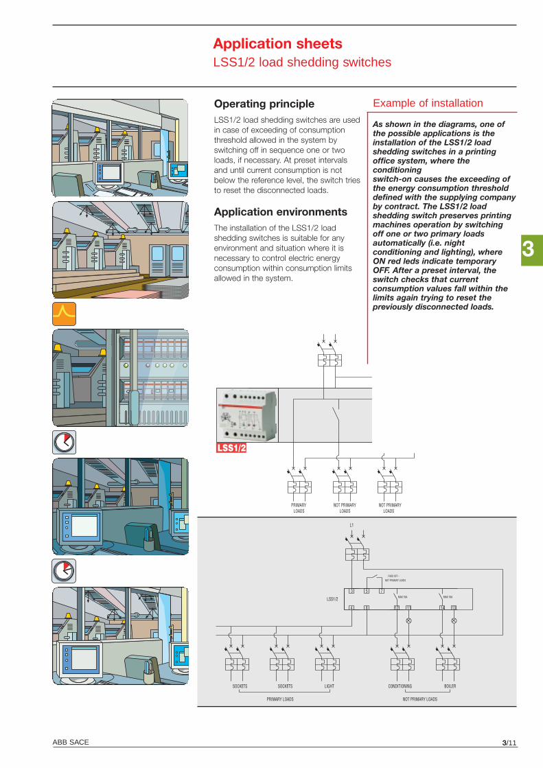
LSS1/2
LOADSPRIMARY
L1 N
LOADSNOT PRIMARY NOT PRIMARY
LOADS
3
ABB SACE 3/11
Application sheetsLSS1/2 load shedding switches
Operating principleLSS1/2 load shedding switches are usedin case of exceeding of consumptionthreshold allowed in the system byswitching off in sequence one or twoloads, if necessary. At preset intervalsand until current consumption is notbelow the reference level, the switch triesto reset the disconnected loads.
Application environmentsThe installation of the LSS1/2 loadshedding switches is suitable for anyenvironment and situation where it isnecessary to control electric energyconsumption within consumption limitsallowed in the system.
Example of installation
As shown in the diagrams, one ofthe possible applications is theinstallation of the LSS1/2 loadshedding switches in a printingoffice system, where theconditioningswitch-on causes the exceeding ofthe energy consumption thresholddefined with the supplying companyby contract. The LSS1/2 loadshedding switch preserves printingmachines operation by switchingoff one or two primary loadsautomatically (i.e. nightconditioning and lighting), whereON red leds indicate temporaryOFF. After a preset interval, theswitch checks that currentconsumption values fall within thelimits again trying to reset thepreviously disconnected loads.
SOCKETS
LSS1/2
L1
3 5 7
4 8 12 11 14 13
SOCKETS LIGHT CONDITIONING BOILER
PRIMARY LOADS NOT PRIMARY LOADS
MAX 16A
FIXED OFF – NOT PRIMARY LOADS
MAX 16A
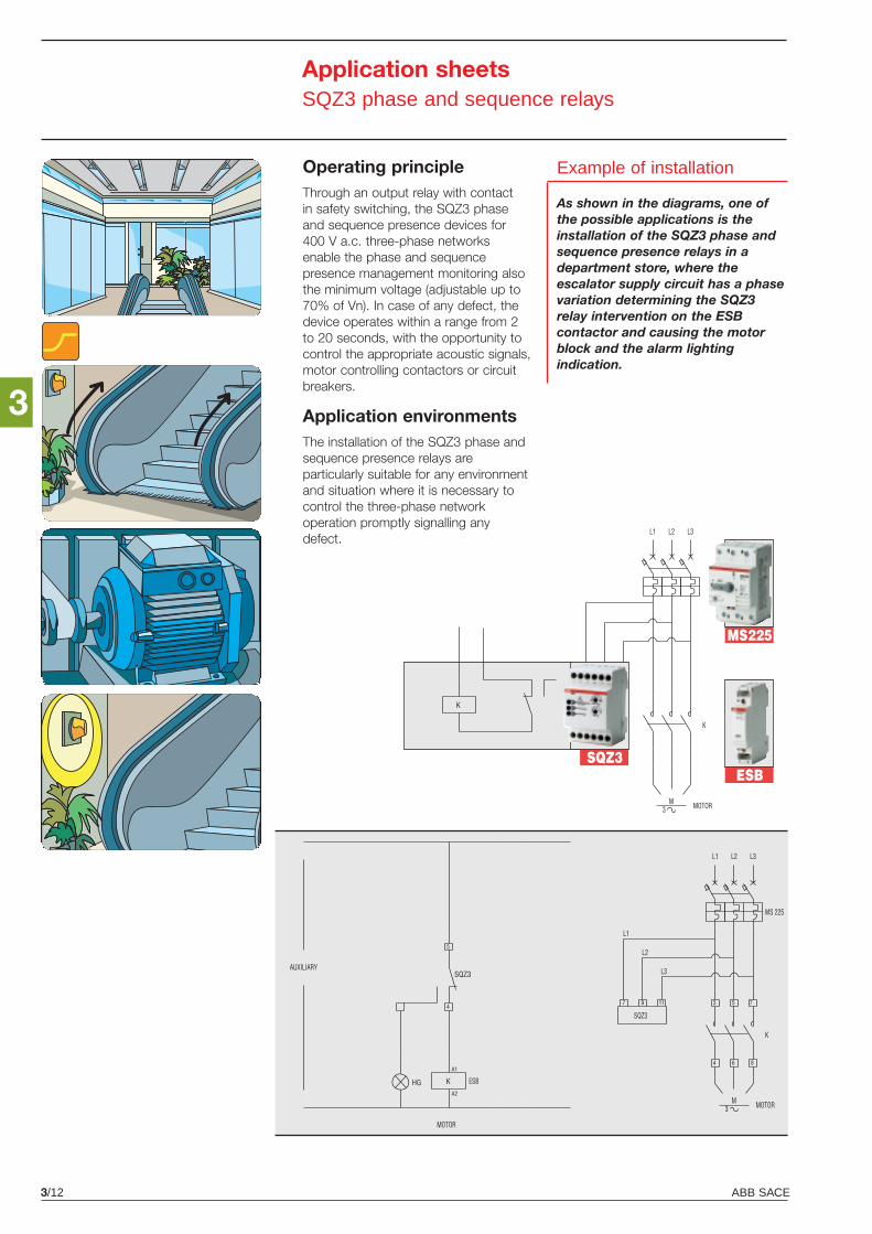
ABB SACE3/12
3
SQZ3ESB
MS225
K
AUXILIARY
FOTO
MOTOR
K
L3L2L1
M3
Application sheetsSQZ3 phase and sequence relays
Operating principleThrough an output relay with contactin safety switching, the SQZ3 phaseand sequence presence devices for400 V a.c. three-phase networksenable the phase and sequencepresence management monitoring alsothe minimum voltage (adjustable up to70% of Vn). In case of any defect, thedevice operates within a range from 2to 20 seconds, with the opportunity tocontrol the appropriate acoustic signals,motor controlling contactors or circuitbreakers.
Application environmentsThe installation of the SQZ3 phase andsequence presence relays areparticularly suitable for any environmentand situation where it is necessary tocontrol the three-phase networkoperation promptly signalling anydefect.
Example of installation
As shown in the diagrams, one ofthe possible applications is theinstallation of the SQZ3 phase andsequence presence relays in adepartment store, where theescalator supply circuit has a phasevariation determining the SQZ3relay intervention on the ESBcontactor and causing the motorblock and the alarm lightingindication.
4
5
MOTOR
AUXILIARY
8
7
6
5
4
31197
KA2
A1
MOTOR
K
MS 225
L3L2L1
ESB
SQZ3
HG
SQZ3
M
L1
L2
L3
3
4
4/1ABB SACE
Overall dimensions
Contents
Protection devices
RD2 residual current monitors and toroidal transformers ........................................................ 4/2
E 930 fuse holders ................................................................................................................. 4/3
M2160 - M2060 fuse switches ............................................................................................... 4/3
Command devices
E 259 installation relays .......................................................................................................... 4/4
E 250 latching relays .............................................................................................................. 4/4
Load management devices
ATS electro-mechanical time switches ................................................................................... 4/5
DTS digital time switches ....................................................................................................... 4/5
TWS twilight switches ............................................................................................................ 4/6
RAL overload alarms .............................................................................................................. 4/7
LSS1/2 load shedding switches ............................................................................................. 4/7
SQZ3 phase and sequence relays .......................................................................................... 4/7
LEE power failure signalling lamp ........................................................................................... 4/8
Max./min. current/voltage ammetric and voltmetric relays ...................................................... 4/8
Measurement devices
Analogue measurement instruments ...................................................................................... 4/9
Digital measurement instruments ........................................................................................... 4/9
MTM multimeters ................................................................................................................. 4/10
Accessories for analogue and digital measurement instruments ........................................... 4/10
HMT electro-mechanical hour meters ................................................................................... 4/24
Insulation monitors ............................................................................................................... 4/25
Other modular devices
TM/TS bell transformers ....................................................................................................... 4/26
Bells and buzzers ................................................................................................................. 4/26
Modular sockets .................................................................................................................. 4/26
M9100 modular housing for CBK pushbuttons .................................................................... 4/27
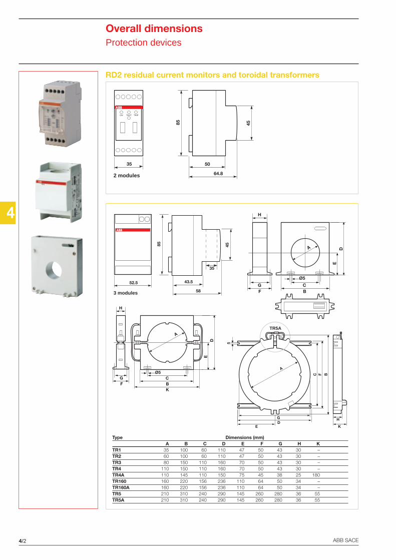
4/2 ABB SACE
4
Type Dimensions (mm)A B C D E F G H K
TR1 35 100 60 110 47 50 43 30 –TR2 60 100 60 110 47 50 43 30 –TR3 80 150 110 160 70 50 43 30 –TR4 110 150 110 160 70 50 43 30 –TR4A 110 145 110 150 75 45 38 25 180TR160 160 220 156 236 110 64 50 34 –TR160A 160 220 156 236 110 64 50 34 –TR5 210 310 240 290 145 260 280 36 55TR5A 210 310 240 290 145 260 280 36 55
50
64.885
35
45
2 modules
ON TEST TRIP
43.5
58
85
52.5
45
35
3 modules
A
FG
H
BC
Ø5
DE
K
FG
D
H
BC
E
Ø5
A
TR5A
EDG
C F B
5
K
H
A
Overall dimensionsProtection devices
RD2 residual current monitors and toroidal transformers
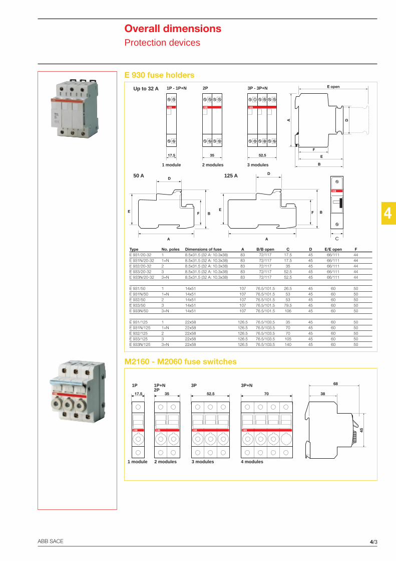
4
4/3ABB SACE
Overall dimensionsProtection devices
E 930 fuse holders
M2160 - M2060 fuse switches
Tipo Nr. poli Dim. fusibile A B/B aperto C D E/E aperto FE 931/20-32 1 8,5 x 31,5 (32A: 10,3 x 38) 83 72/107 17,5 45 65/102 44E 931N/20-32 1+N 8,5 x 31,5 (32A: 10,3 x 38) 83 72/107 17,5 45 65/102 44E 932/20-32 2 8,5 x 31,5 (32A: 10,3 x 38) 83 72/107 35 45 65/102 44E 933/20-32 3 8,5 x 31,5 (32A: 10,3 x 38) 83 72/107 52,5 45 65/102 44E 933N/20-32 3+N 8,5 x 31,5 (32A: 10,3 x 38) 83 72/107 52,5 45 65/102 44
E 931/50 1 14 x 51 107 76/104 21 45 60 50E 931N/50 1+N 14 x 51 107 76/104 42 45 60 50E 932/50 2 14 x 51 107 76/104 42 45 60 50E 933/50 3 14 x 51 107 76/104 63 45 60 50E 933N/50 3+N 14 x 51 107 76/104 84 45 60 50
E 931/125 1 22 x 58 124 76/104 35 45 60 50E 931N/125 1+N 22 x 58 124 76/104 70 45 60 50E 932/125 2 22 x 58 124 76/104 70 45 60 50E 933/125 3 22 x 58 124 76/104 105 45 60 50E 933N/125 3+N 22 x 58 124 76/104 140 45 60 50
1 module 2 modules 3 modules 4 modules
1P 1P+N2P
3P 3P+N 68
45
3817.5 35 52.5 70
A
D
BFE
D
A
BFE
C
1 module 2 modules 3 modules
1P - 1P+N 2P 3P - 3P+N
17.5 35 52.5
Up to 32 A
50 A 125 A
D
E
E open
F
B
A
Type No. poles Dimensions of fuse A B/B open C D E/E open FE 931/20-32 1 8.5x31.5 (32 A: 10.3x38) 83 72/117 17.5 45 66/111 44E 931N/20-32 1+N 8.5x31.5 (32 A: 10.3x38) 83 72/117 17.5 45 66/111 44E 932/20-32 2 8.5x31.5 (32 A: 10.3x38) 83 72/117 35 45 66/111 44E 933/20-32 3 8.5x31.5 (32 A: 10.3x38) 83 72/117 52.5 45 66/111 44E 933N/20-32 3+N 8.5x31.5 (32 A: 10.3x38) 83 72/117 52.5 45 66/111 44
E 931/50 1 14x51 107 76.5/101.5 26.5 45 60 50E 931N/50 1+N 14x51 107 76.5/101.5 53 45 60 50E 932/50 2 14x51 107 76.5/101.5 53 45 60 50E 933/50 3 14x51 107 76.5/101.5 79.5 45 60 50E 933N/50 3+N 14x51 107 76.5/101.5 106 45 60 50
E 931/125 1 22x58 126.5 76.5/103.5 35 45 60 50E 931N/125 1+N 22x58 126.5 76.5/103.5 70 45 60 50E 932/125 2 22x58 126.5 76.5/103.5 70 45 60 50E 933/125 3 22x58 126.5 76.5/103.5 105 45 60 50E 933N/125 3+N 22x58 126.5 76.5/103.5 140 45 60 50
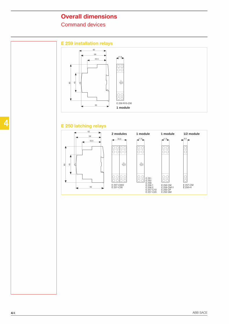
4
4/4 ABB SACE
1 module
62
58
43.5
65
35.6 17.8 17.8 8.9
4585
E 257-C003E 257-C30
E 251E 252E 256E 256.1E 256.2E 257-C10E 257-C20
E 250 CME 259 CM11E 250 CPE 250 GM
E 257-CME 250-H
62
58
43.5
65
17.8
4585
E 259 R10-230
2 modules 1 module 1 module 1/2 module
Overall dimensionsCommand devices
E 259 installation relays
E 250 latching relays
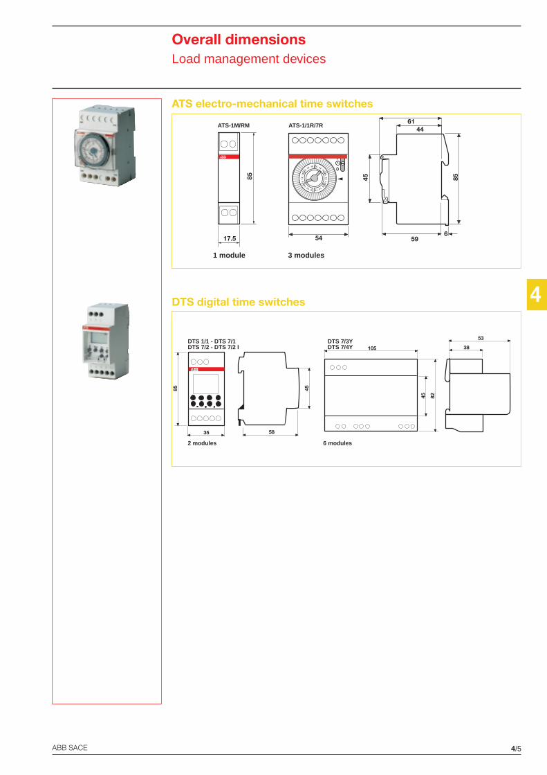
4
4/5ABB SACE
1 module
ATS-1M/RM
2 modules 6 modules
DTS 1/1 - DTS 7/1DTS 7/2 - DTS 7/2 I
DTS 7/3YDTS 7/4Y
45
58
85
35
105
45 82
53
38
45
6144
596
85
612
186
1218
6
12 18 6 12
186
1218
6
1218
1
0
54
ATS-1/1R/7R
3 modules85
17.5
Overall dimensionsLoad management devices
ATS electro-mechanical time switches
DTS digital time switches
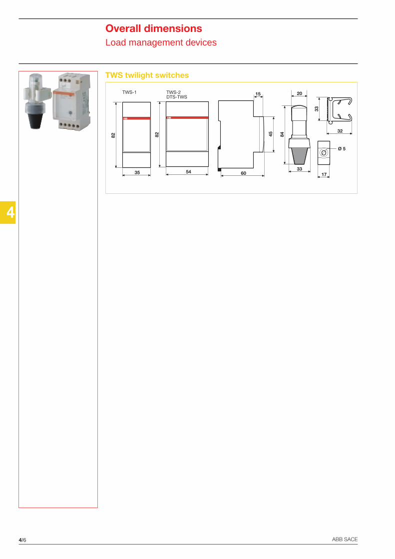
4/6 ABB SACE
4
Overall dimensionsLoad management devices
TWS twilight switches
84
33
20
33
32
17
Ø 5
TWS-1 TWS-2DTS-TWS
82
35 60
45
15
82
54
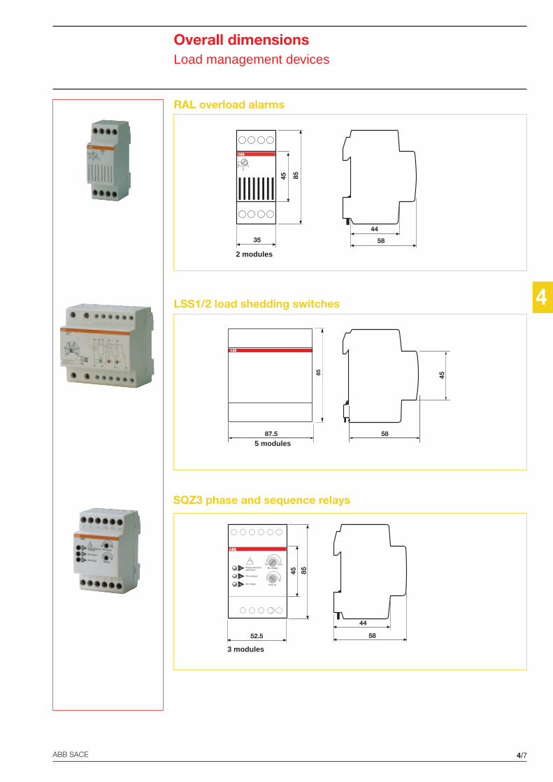
4
4/7ABB SACE
2 modules
45 85
35
12
3
58
44
4558
5 modules
85
87.5
3 modules
58
44
45 85
52.5
Phases Sequence400V 50Hz
OK
OK
OK
Three phases
Min Voltage
Min Voltage
Delay (s)
70% 100%
2 20
SQZ3 phase and sequence relays
Overall dimensionsLoad management devices
RAL overload alarms
LSS1/2 load shedding switches
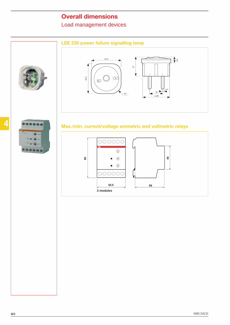
4/8 ABB SACE
4
Overall dimensionsLoad management devices
LEE 230 power failure signalling lamp
Max./min. current/voltage ammetric and voltmetric relays27
ø 38
19
ø 4
8.5
42.5
42.5
R1
3 modules
45
5852.5
85
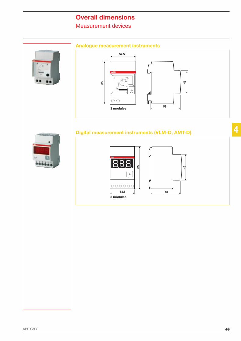
4
4/9ABB SACE
3 modules
52.5
85
58
45
V
200
400
3 modules
A
52.5
85
58
45
Overall dimensionsMeasurement devices
Analogue measurement instruments
Digital measurement instruments (VLM-D, AMT-D)
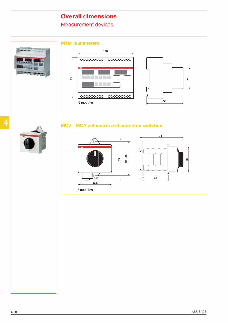
4/10 ABB SACE
472
52.5
56...
58
45
75
43
3 modules
58
45
6 modules
105
90
Overall dimensionsMeasurement devices
MTM multimeters
MCV - MCA voltmetric and ammetric switches
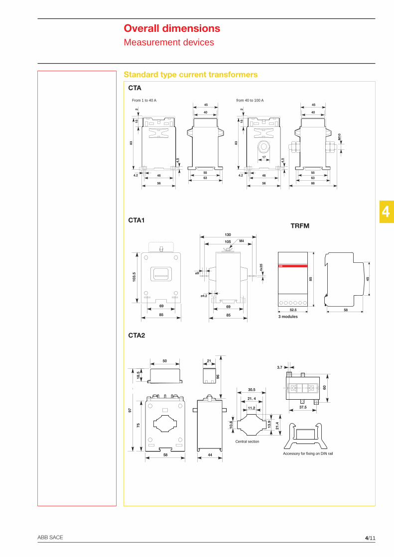
4
4/11ABB SACE
CTA
CTA1
CTA2
TRFM
3 modules
52.5 58
4585
Central section
21. 4
11.2
30.5
10.8
13.9
21.4
37.5
3.7
60
Accessory for fixing on DIN rail
75
50 21
18.5
58 44
97
96
56
55
63
40
45
464.2
83
215
4.517
M10
8856
55
63
40
45
464.2
83
215
4.5
From 1 to 40 A from 40 to 100 A
130
103.
5
85 85
69 69
ø4.2
ø9
105 M4
4x35
Overall dimensionsMeasurement devices
Standard type current transformers
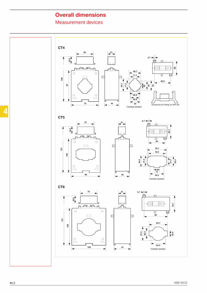
4/12 ABB SACE
4
CT4
CT5
CT6
Overall dimensionsMeasurement devices
21
61
82
3.7
76.7
100
75
18.5
105
121
Central section
20.4
22.5
51.3
64.7
54.4
54
3.7
60.7
21
45
100
75
18.5
85
121
Central section
34.2
42.2
52.1
31.3
21.4
25.3
12
34.3
87
50
18.5
75
109
21
44
45.5
3.7
60
Central section
11.1
20.9
11,2
40.7
40.7
25.8
33
20 25 30
Accessory for fixing on DIN rail
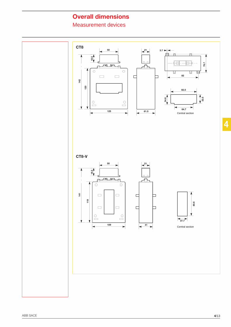
4
4/13ABB SACE
CT8
CT8-V
Overall dimensionsMeasurement devices
21
61.5
82
3.7
76.7
120
50
18.5
125
142
Central section
32.5
64.7
82.5
34.6
21
41
119
50
18.5
109
141
Central section
37.7
80.6
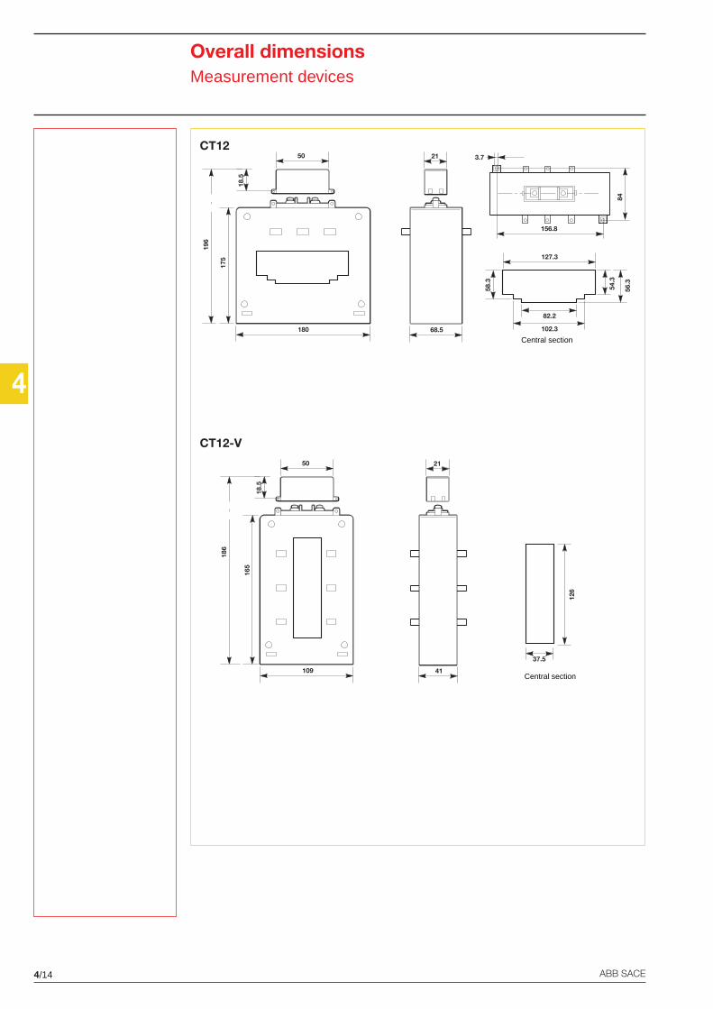
4/14 ABB SACE
4
CT12
CT12-V
Overall dimensionsMeasurement devices
21
68.5
156.8
3.7
84
175
50
18.5
180
196
Central section
54.3
82.2
127.3
58.3
56.3
102.3
Central section
37.5
126
165
50
18.5
109
186
21
41
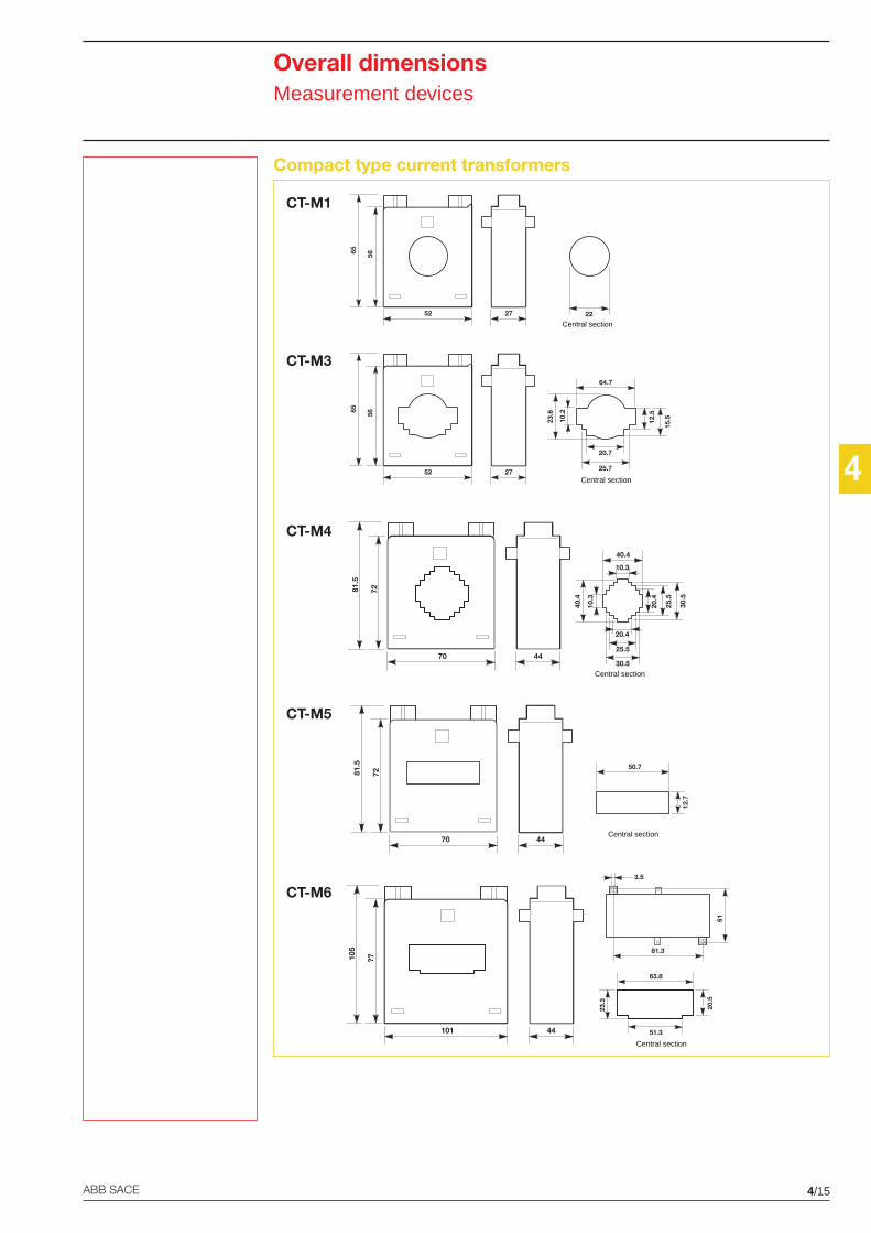
4
4/15ABB SACE
CT-M1
CT-M3
CT-M4
CT-M5
CT-M6
Overall dimensionsMeasurement devices
Compact type current transformers
56
52
65
27
Central section22
72
70
81.5
44Central section
12.7
50.7
40.4
40.4
25.5
30.520
.4
25.5
30.5
72
70
81.5
44
10.3
20.4
10.3
Central section
56
52
65
27Central section
10.2
12.5
23.6
64.7
25.7
20.7
15.5
Central section
20.5
51.3
63.8
23.3
??
101
105
44
81.3
61
3.5
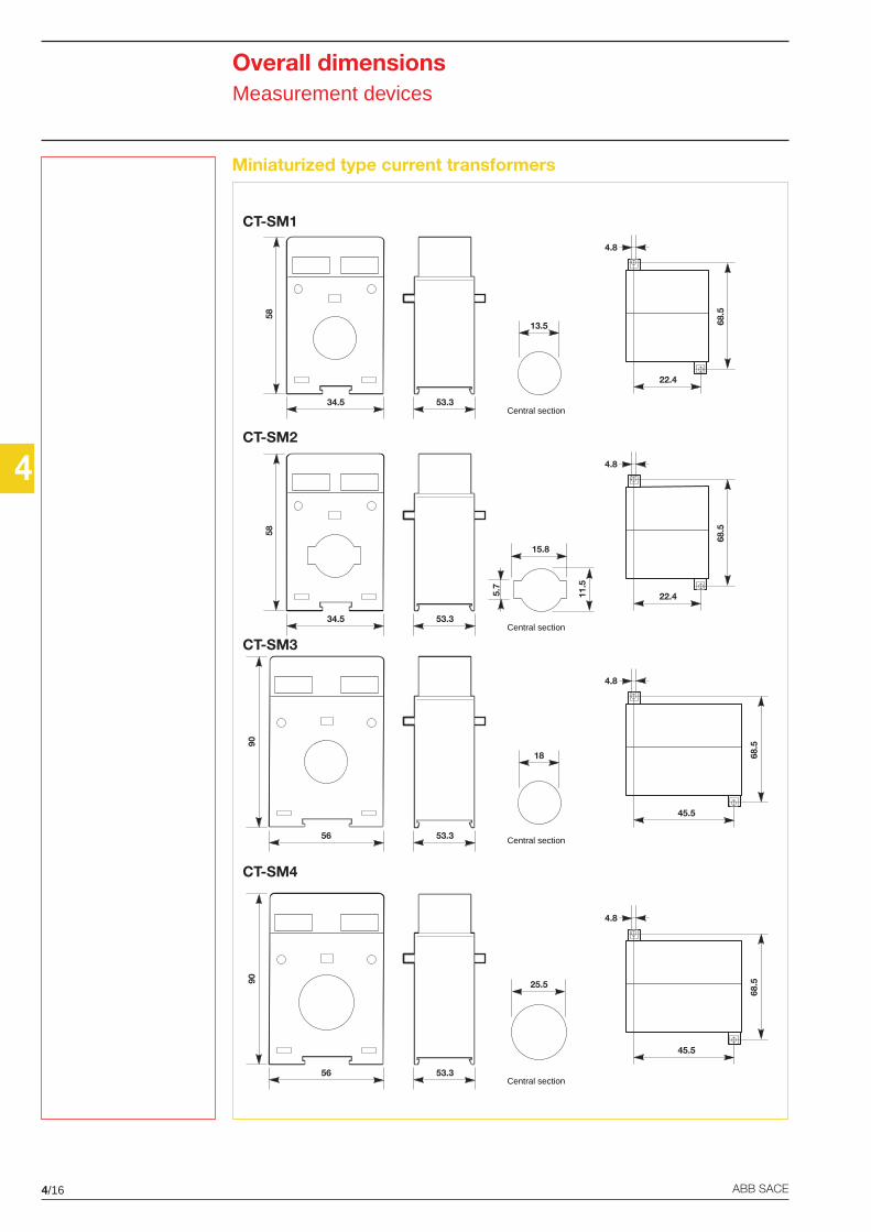
4/16 ABB SACE
4
CT-SM1
CT-SM2
CT-SM3
CT-SM4
Overall dimensionsMeasurement devices
Miniaturized type current transformers
58
34.5 53.3Central section
13.5
22.4
4.8
68.5
90
56 53.3
45.5
4.8
68.5
Central section
18
90
56 53.3
45.5
4.8
68.5
Central section
25.5
58
34.5 53.3Central section
15.8
5.7
11.5
22.4
4.8
68.5
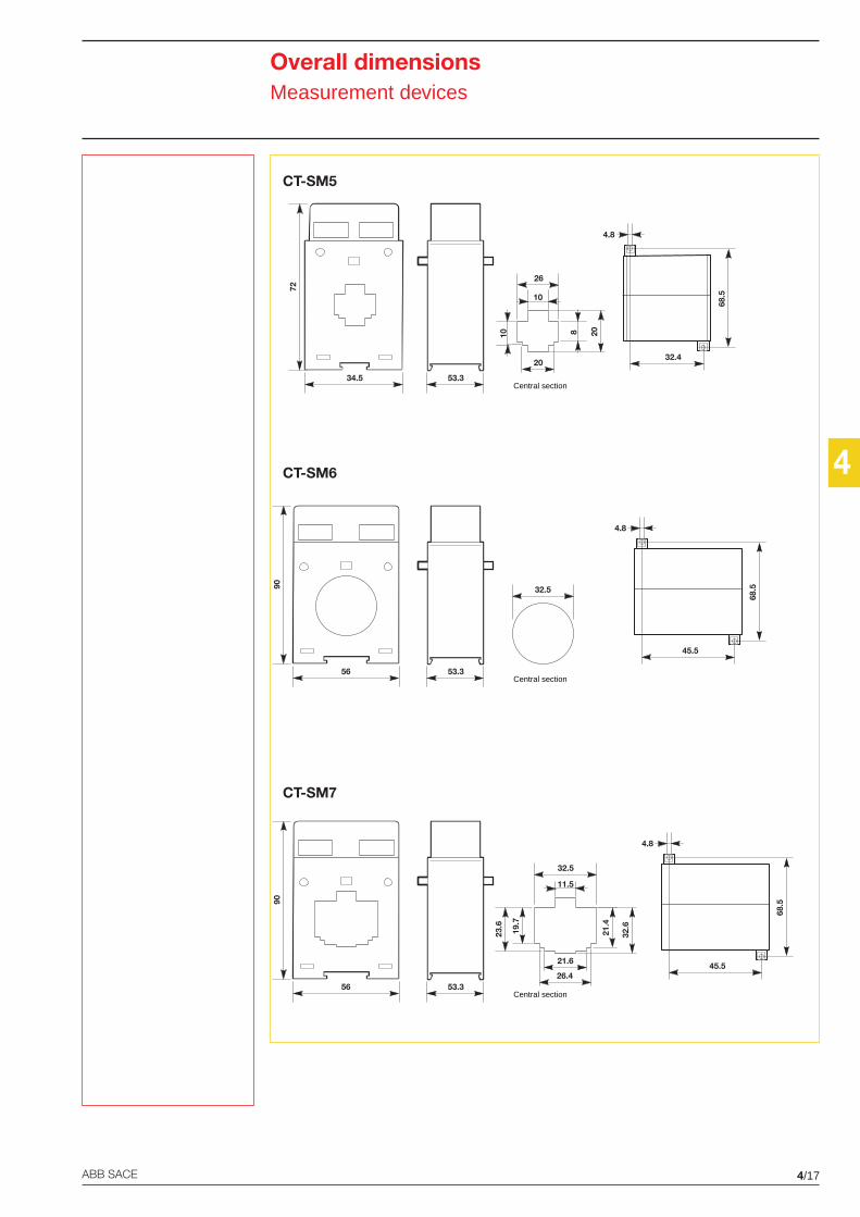
4
4/17ABB SACE
CT-SM5
CT-SM6
CT-SM7
Overall dimensionsMeasurement devices
90
56 53.3
45.5
4.8
68.5
Central section
32.5
90
56 53.3
45.5
4.8
68.5
Central section
21.6
11.5
32.5
32.6
21.4
26.4
23.6
19.7
72
34.5 53.3Central section
32.4
4.8
68.5
20
10
26
10 8 20
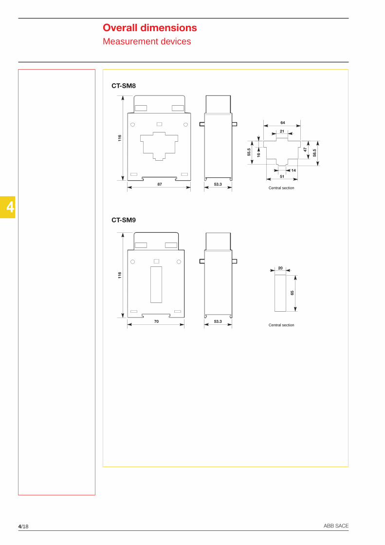
4/18 ABB SACE
4
CT-SM8
CT-SM9
Overall dimensionsMeasurement devices
116
87 53.3Central section
21
64
58.547
51
55.5
14
16
116
70 53.3Central section
20
65
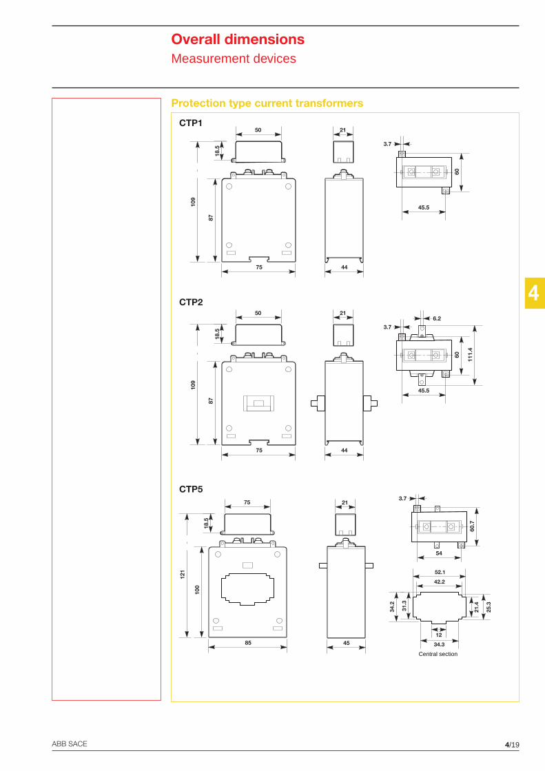
4
4/19ABB SACE
CTP1
CTP2
CTP5
Overall dimensionsMeasurement devices
Protection type current transformers
87
50
18.5
75
109
21
44
45.5
3.7
60
87
50
18.5
75
109
21
44
45.5
111.
4
3.7
60
6.2
54
3.7
60.7
21
45
100
75
18.5
85
121
Central section
34.2
42.2
52.1
31.3
21.4
25.3
12
34.3
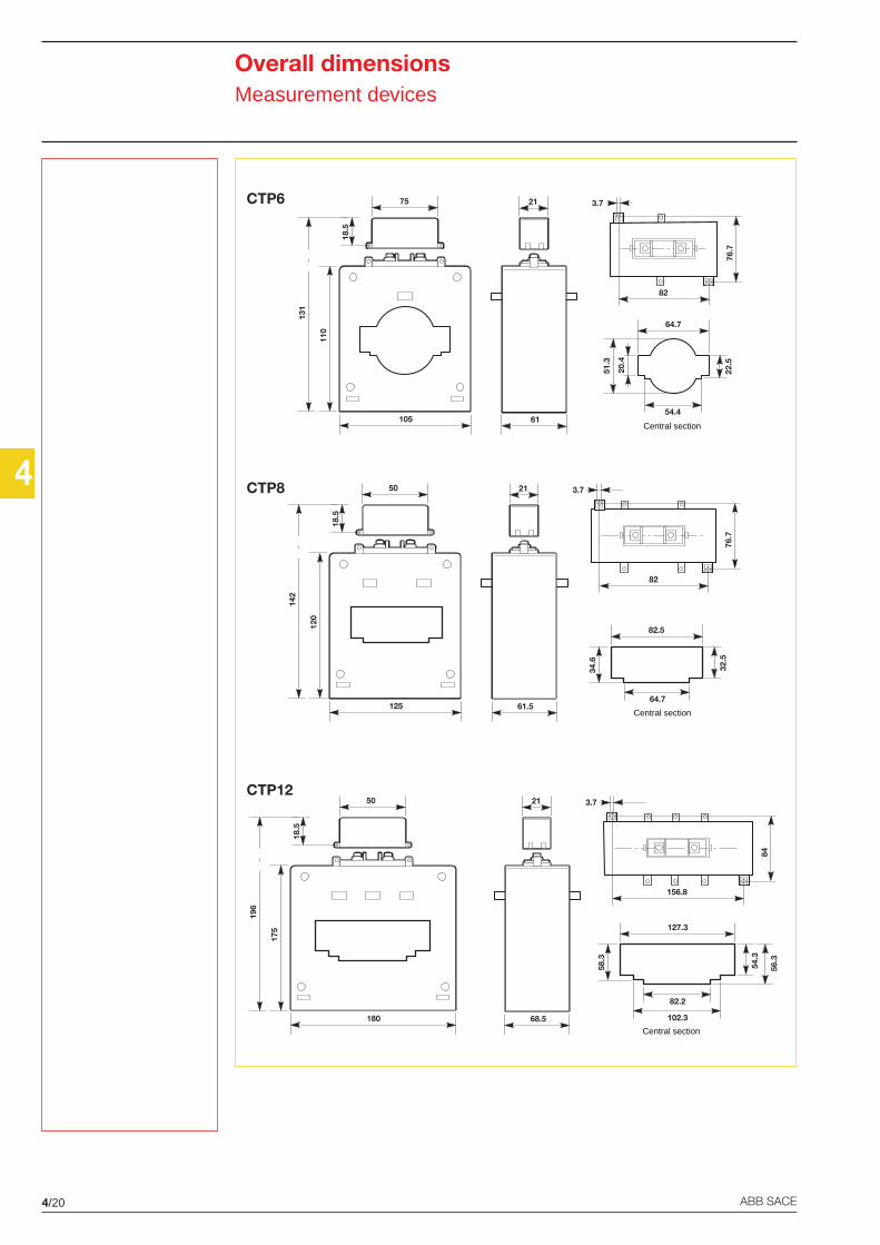
4/20 ABB SACE
4
CTP6
CTP8
CTP12
Overall dimensionsMeasurement devices
21
61
82
3.7
76.7
110
75
18.5
105
131
Central section
20.4
22.5
51.3
64.7
54.4
21
68.5
156.8
3.7
84
175
50
18.5
180
196
Central section
54.3
82.2
127.3
58.3
56.3
102.3
21
61.5
82
3.7
76.7
120
50
18.5
125
142
Central section32
.5
64.7
82.5
34.6
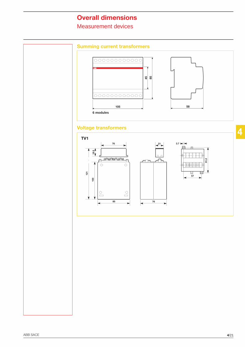
4
4/21ABB SACE
Overall dimensionsMeasurement devices
Summing current transformers
Voltage transformers
TV121
76
57
3.7
91.2
100
76
18.5
85
121
6 modules
58
45 85
105
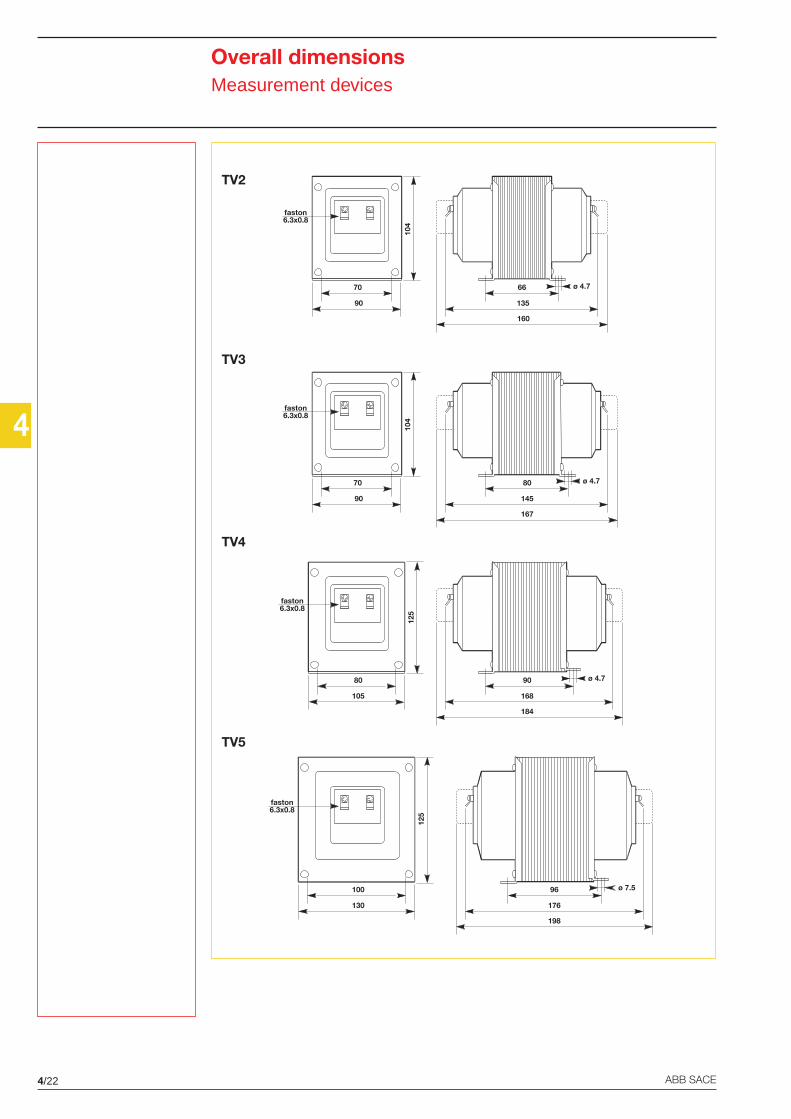
4/22 ABB SACE
4
Overall dimensionsMeasurement devices
TV2
TV3
TV4
TV5
90
104
70
faston6.3x0.8
145
80
167
ø 4.7
90
104
70
faston6.3x0.8
135
66
160
ø 4.7
105
125
80
faston6.3x0.8
168
90
184
ø 4.7
176
96
198
ø 7.5
130
125
100
faston6.3x0.8
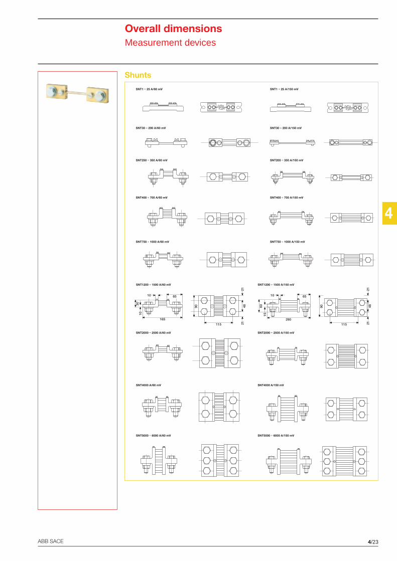
4
4/23ABB SACE
Overall dimensionsMeasurement devices
Shunts
SNT1200 ÷ 1500 A/60 mV SNT1200 ÷ 1500 A/150 mV
SNT2000 ÷ 2500 A/60 mV SNT2000 ÷ 2500 A/150 mV
SNT4000 A/60 mV SNT4000 A/150 mV
SNT5000 ÷ 6000 A/60 mV SNT5000 ÷ 6000 A/150 mV
90115
4821
21
15
65
60
10
290
10
65
30
10
165
90
115
4821
21
SNT1 ÷ 25 A/60 mV SNT1 ÷ 25 A/150 mV
SNT30 ÷ 200 A/60 mV SNT30 ÷ 200 A/150 mV
SNT250 ÷ 350 A/60 mV SNT200 ÷ 350 A/150 mV
SNT400 ÷ 700 A/60 mV SNT400 ÷ 700 A/150 mV
SNT750 ÷ 1000 A/60 mV SNT750 ÷ 1000 A/150 mV
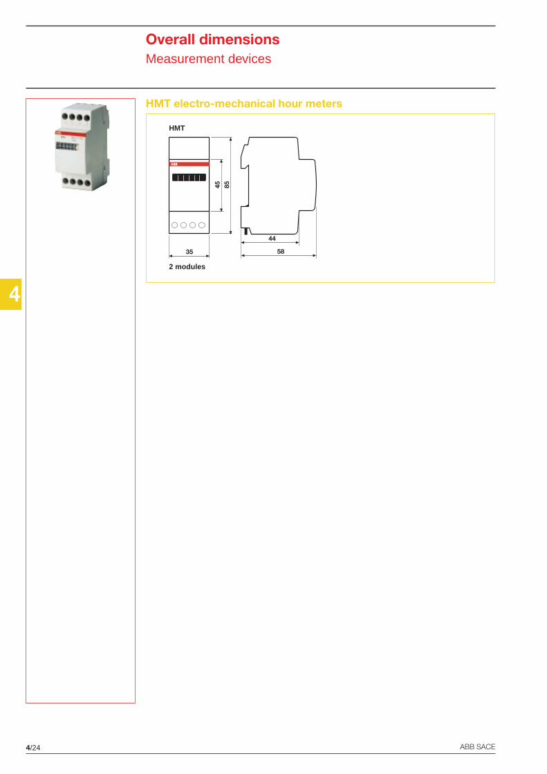
4/24 ABB SACE
4
Overall dimensionsMeasurement devices
HMT electro-mechanical hour meters
2 modules
HMT
58
44
45 85
35
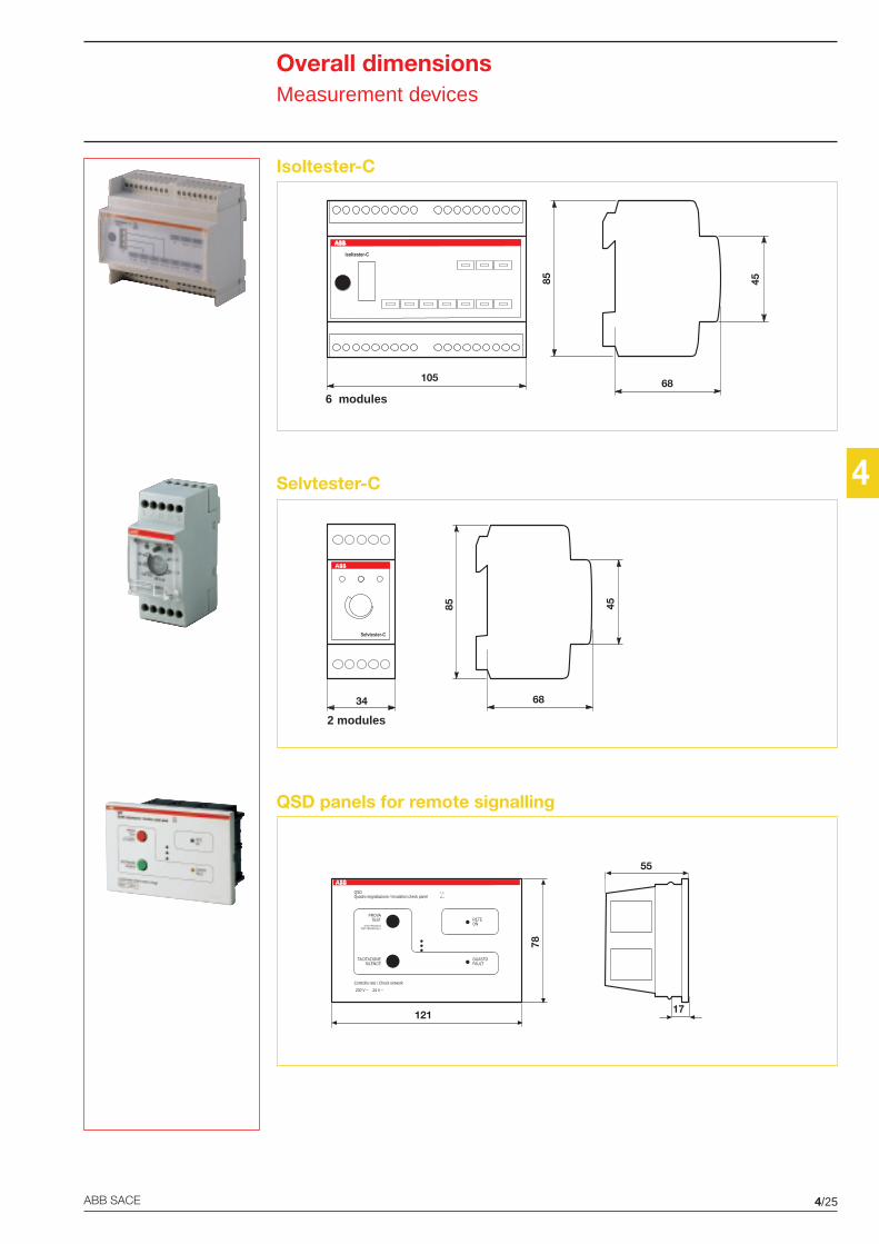
4
4/25ABB SACE
Overall dimensionsMeasurement devices
Isoltester-C
Selvtester-C
QSD panels for remote signalling
17
55
121
78
QSDQuadro segnalazione / Insulation check panel
Controllo rete / Check network
TACITAZIONESILENCE
PROVATEST RETE
ON
GUASTOFAULT
C EI
64.4
TEST PERIODICOTEST PERIODICALLY
230 V ~ 24 V ~
6 modules68
85 45
105
Isoltester-C
2 modules
68
85 45
34
Selvtester-C
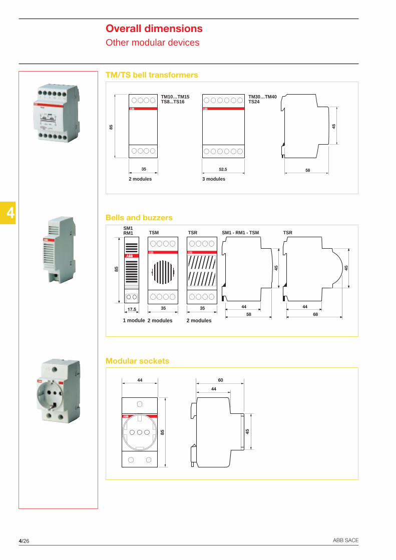
4/26 ABB SACE
4
Overall dimensionsOther modular devices
TM/TS bell transformers
Bells and buzzers
Modular sockets
44
85
60
45
44
2 modules
TM10…TM15TS8...TS16
TM30…TM40TS24
3 modules
45
5852.535
85
1 module
45
58
4417.5
85
2 modules
35
SM1RM1 TSM
2 modules
35
TSR
45
68
44
SM1 - RM1 - TSM TSR
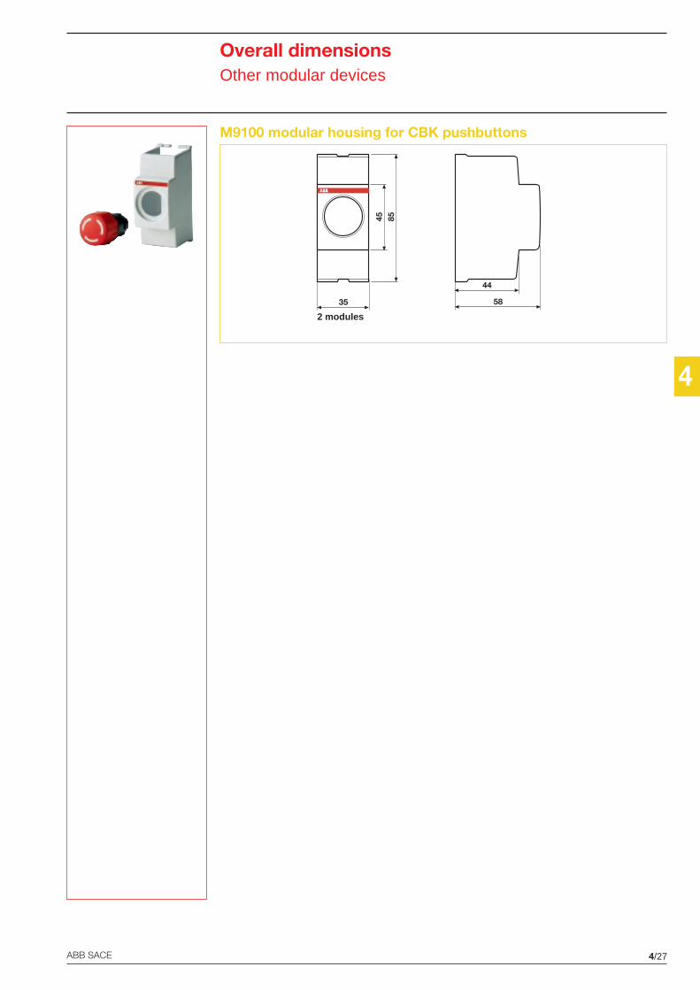
4
4/27ABB SACE
Overall dimensionsOther modular devices
M9100 modular housing for CBK pushbuttons
2 modules
58
44
45 85
35

2CSC440001D0201
System pro MProtection, command,load management and measurementmodular devices
Technical catalogue
2CS
C44
0001
D02
01 -
Feb
brai
o ’0
4P
rinte
d in
Ital
y10
.000
- C
AL
Sys
tem
pro
M P
rote
ctio
n, c
omm
and,
load
man
agem
ent a
nd m
easu
rem
ent m
odul
ar d
e vic
es
In consideration of modifications to Standards and materials,the characteristics and overall dimensions indicated in thiscatalogue may be considered binding only following confirmationby ABB SACE
ABB SACE S.p.AAn ABB Group company
Line Protection DevicesViale dell’Industria, 1820010 Vittuone (MI) - ItalyTel.: +39.02.9034.1 - Telefax: +39.02.9034.7609
http://www.abb.com
0 Cop 12-05-2004, 10:531