technical catalog - eaton
TRANSCRIPT

Gear pumps and motors
Technical catalog
Series 26 pumps Series 26 motors Series L2 pumps

2 GEAR PUMPS AND MOTORS E-PUGE-MC001-E3 October 2016 www.eaton.com
SERIES 26 PUMPSFeatures . . . . . . . . . . . . . . . . . . . . . . . . . . . . . . . . . . . . . . . . . . . . . . . . . . . . . . . . . . . . . . . . . . . . . . . . . . . . . . . . . . . . . 3
General specifications and performance data . . . . . . . . . . . . . . . . . . . . . . . . . . . . . . . . . . . . . . . . . . . . . . . . . . . . . . . . . 4
Performance data charts . . . . . . . . . . . . . . . . . . . . . . . . . . . . . . . . . . . . . . . . . . . . . . . . . . . . . . . . . . . . . . . . . . . . . . . . . 5
Standard catalog assemblies - dimensions . . . . . . . . . . . . . . . . . . . . . . . . . . . . . . . . . . . . . . . . . . . . . . . . . . . . . . . . . . . 9
Order numbers . . . . . . . . . . . . . . . . . . . . . . . . . . . . . . . . . . . . . . . . . . . . . . . . . . . . . . . . . . . . . . . . . . . . . . . . . . . . . . . 10
Optional configurations . . . . . . . . . . . . . . . . . . . . . . . . . . . . . . . . . . . . . . . . . . . . . . . . . . . . . . . . . . . . . . . . . . . . . . . . . 13
Component parts - dimensions . . . . . . . . . . . . . . . . . . . . . . . . . . . . . . . . . . . . . . . . . . . . . . . . . . . . . . . . . . . . . . . . . . . 14
Model code - single . . . . . . . . . . . . . . . . . . . . . . . . . . . . . . . . . . . . . . . . . . . . . . . . . . . . . . . . . . . . . . . . . . . . . . . . . . . . 17
Model code - multiple . . . . . . . . . . . . . . . . . . . . . . . . . . . . . . . . . . . . . . . . . . . . . . . . . . . . . . . . . . . . . . . . . . . . . . . . . . 19
Side-load applications . . . . . . . . . . . . . . . . . . . . . . . . . . . . . . . . . . . . . . . . . . . . . . . . . . . . . . . . . . . . . . . . . . . . . . . . . . 22
Load sensing priority valve . . . . . . . . . . . . . . . . . . . . . . . . . . . . . . . . . . . . . . . . . . . . . . . . . . . . . . . . . . . . . . . . . . . . . . 24
SERIES 26 MOTORSGeneral specifications . . . . . . . . . . . . . . . . . . . . . . . . . . . . . . . . . . . . . . . . . . . . . . . . . . . . . . . . . . . . . . . . . . . . . . . . . . 25
Performance data . . . . . . . . . . . . . . . . . . . . . . . . . . . . . . . . . . . . . . . . . . . . . . . . . . . . . . . . . . . . . . . . . . . . . . . . . . . . . 26
Model code - single . . . . . . . . . . . . . . . . . . . . . . . . . . . . . . . . . . . . . . . . . . . . . . . . . . . . . . . . . . . . . . . . . . . . . . . . . . . . 28
SERIES L2 PUMPSGeneral specifications and performance data . . . . . . . . . . . . . . . . . . . . . . . . . . . . . . . . . . . . . . . . . . . . . . . . . . . . . . . . 30
Performance data charts . . . . . . . . . . . . . . . . . . . . . . . . . . . . . . . . . . . . . . . . . . . . . . . . . . . . . . . . . . . . . . . . . . . . . . . . 31
Standard catalog assemblies - dimensions . . . . . . . . . . . . . . . . . . . . . . . . . . . . . . . . . . . . . . . . . . . . . . . . . . . . . . . . . . 33
Order numbers . . . . . . . . . . . . . . . . . . . . . . . . . . . . . . . . . . . . . . . . . . . . . . . . . . . . . . . . . . . . . . . . . . . . . . . . . . . . . . . 34
Optional configurations . . . . . . . . . . . . . . . . . . . . . . . . . . . . . . . . . . . . . . . . . . . . . . . . . . . . . . . . . . . . . . . . . . . . . . . . . 36
Component parts - dimensions . . . . . . . . . . . . . . . . . . . . . . . . . . . . . . . . . . . . . . . . . . . . . . . . . . . . . . . . . . . . . . . . . . . 37
Model code - single . . . . . . . . . . . . . . . . . . . . . . . . . . . . . . . . . . . . . . . . . . . . . . . . . . . . . . . . . . . . . . . . . . . . . . . . . . . . 40
Model code - multiple . . . . . . . . . . . . . . . . . . . . . . . . . . . . . . . . . . . . . . . . . . . . . . . . . . . . . . . . . . . . . . . . . . . . . . . . . . 42
TABLE OF CONTENTS

3GEAR PUMPS AND MOTORS E-PUGE-MC001-E3 October 2016 www.eaton.com
Series 26 pump Features
Quiet operation
• The 13-tooth gears, versus 10 teeth in previous pumps, minimizes the flow ripple . This reduces noise as well as vibration .
• The improved trap reliefs not only increase power, they also help keep oil flowing smoothly to reduce noise .
Improved efficiency
• Improved bearing lubrication system uses inlet oil instead of high pressure oil, improving volumetric efficiency for more power output .
• The highly polished shaft and gears improve mechanical efficiency and reduce wear on these components, adding to the service life and reliability of the pump .
• The optimized trapped oil relief areas help reduce pressure ripple for quieter operation . This also decreases the input power requirements .
Field reversible
• The innovative new wea plate permits simple field reversibility of the pump direction . Simply open the pump, switch the drive gear and idler gear, reposition the plug and reassemble . No extra parts are needed .
Interchangeability
• The Series 26 Gear Pump has been designed to retrofit equipment using the B1 and B2 Gear Pumps . Extra shafts, porting, and mounting configurations, as well as 13 available displacements, give you the choices you need for an easy conversion to this superior pump .
Pressures to 3500 PSI and flow to 24.1 GPM

4 GEAR PUMPS AND MOTORS E-PUGE-MC001-E3 October 2016 www.eaton.com
Series 26 pumpGeneral specifications and performance data
Rotation Field reversible
Mounting flange SAE A 2 BoltMax. Continuous pressure† 210 bar [3000 PSI]*Max. Intermittent pressure†† 240 bar [3500 PSI]**Minimum speed at continuous pressure 750 RPMMaximum rotating torque at 0 pressure 4 Nm [36 lb-in]Maximum continuous operating temperature 105°C [220°F]Minimum continuous oil viscocity 5.7 cSt [45 SUS]Minimum operating temperature -29°C [-20°F]Maximum inlet vacuum at operating condition 0,8 bar Abs. [11.6 psi Abs.]
Displacement cm³/r [in³/r]6,6[.40]
8,2[.50]
9,5[.58]
10,8[.66]
13,8[.84]
16,7[1.02]
19,7[1.20]
Max. Intermittent pressure bar [PSI] 241[3500]
241[3500]
241[3500]
241[3500]
241[3500]
241[3500]
241[3500]
Rated speed (RPM) 3600 3600 3600 3600 3600 3600 3200Minimum output flow at 207 bar [3000 PSI]and rated speed LPM [GPM]
20,1[5.3]
25,0[6.6]
29,5[7.8]
33,7[8.9]
43,5[11.5]
55,3[14.6]
57,9[15.3]
Input power at 207 bar [3000 PSI] andrated speed and cont. Pressure kW [HP]
9,7[13.0]
11,9[15.9]
14,1[18.9]
15,5[20.8]
20,0[26.8]
22,0[29,4]
26,2[35.2]
Displacement cm³/r [in³/r]22,5[1.37]
24,3[1.48]
25,2[1.54]
27,7[1.69]
29,0[1.77]
30,6[1.87]
Max. Intermittent pressure bar [PSI] 241[3500]
241[3500]
241[3500]
241[3500]
234[3400]
224[3250]
Rated speed (RPM) 3000 3000 3000 3000 3000 3000Minimum output flow at 207 bar [3000 PSI]and rated speed LPM [GPM]
62,1[16.4]
67,0[17.7]
69,7[18.4]
76,5[20.2]
79,9[21.1]
84,4[22.3]
Input power at 207 bar [3000 PSI] andrated speed and cont. Pressure kW [HP]
27,3[36.6]
30,5[40.9]
31,0[41.6]
33,4[44.8]
35,4[47.4]
37,4[50.1]
† Continuous - pump may be run continuously at these ratings .†† Intermittent - intermittent operation, 10% of every minute .* 30 .6 cm³/rev . [1 .87 in³/rev .] displacement max . continuous pressure is 190 bar [2750 PSI] .** 30 .6 cm³/rev . [1 .87 in³/rev .] displacement max . intermittent pressure is 224 bar [3250 PSI] .For side load limits consult your Eaton representative .
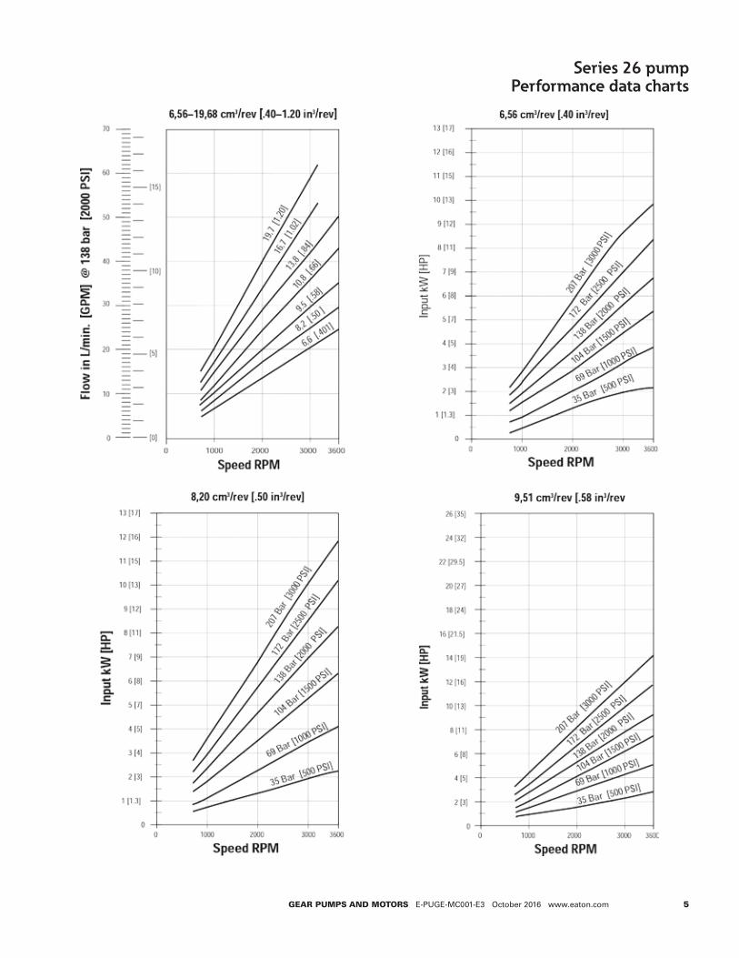
The performance data in the table above and the following graphs was collected using a mineral base oil with a viscosity of 133 SUS at 49°C [120°F] .
5GEAR PUMPS AND MOTORS E-PUGE-MC001-E3 October 2016 www.eaton.com
Series 26 pumpPerformance data charts

6 GEAR PUMPS AND MOTORS E-PUGE-MC001-E3 October 2016 www.eaton.com
Series 26 pumpPerformance data charts

7GEAR PUMPS AND MOTORS E-PUGE-MC001-E3 October 2016 www.eaton.com
Series 26 pumpPerformance data charts

8 GEAR PUMPS AND MOTORS E-PUGE-MC001-E3 October 2016 www.eaton.com
Series 26 pumpPerformance data charts
207
bar [
3000
psi]
207
bar [
3000
psi]
207
bar [
3000
psi]

9GEAR PUMPS AND MOTORS E-PUGE-MC001-E3 October 2016 www.eaton.com
Model 26001 26002 26003 26004 26005 26006 26007
Displacement (cm³/r [in³/r]) 6.6 [.40] 8.2 [.50] 9.5 [.58] 10.8 [.66] 13.8 [.84] 16.7 [1.02] 19.7 [1.20]Dimension A (mm [in]) 72.6 [2.86] 74.3 [2.93] 75.9 [2.99] 77.5 [3.05] 80.7 [3.18] 83.9 [3.30] 87.1 [3.43]Dimension B (mm [in]) 93.2 [3.67] 94.9 [3.74] 96.5 [3.80] 98.1 [3.86] 101.3 [3.99] 104.5 [4.11] 107.7 [4.24]
Series 26 pumpStandard catalog assemblies - dimensions
All dimensions are in mm
*Multiple pump input torque limitations:
The total torque for multiple pump displacements and pressure combinations cannot exceed the maximum input torque rating of the shaft . The proper formula is pressure times displacement divided by 6 .28 .
Left hand rotation shown
Pressure portRear portingSuction port
Rear porting
25.9[1.02]
21.1[.83]
Driveshaftcenterline
18[.71]
Suction portSide porting
46.2[1.82]
92.5[3.64]
Left hand rotation shown
83.3[3.28]
47.6[1.88]
130.0[5.12]
106.4[4.19]
18[.71]
2X Dim A Pressure portSide porting
Dim B
See shaftdrawing
Dia.82.52±.030
[3.249±.001]
6.4[.25]
15.0[.59]
2X Dia. 11.56±.13[.455±.005]
CL
CL
5/8 Inch 9 tooth spline maximum input torque 62 nm [550 lb-in]
3/4 Inch 11 tooth spline maximum input torque 119 nm [1050 lb-in]
3/4 Inch straight key maximum input torque 113 nm [1000 lb-in]
5/8 Inch straight key maximum input torque 56 nm [500 lb-in]
31.8[1.25]
9 Tooth 16/32 DP 30° Involute �at root class 1 Side �t spline SAE J498b22.4 [.88] Min full spline
31.7[1.25]
11 Tooth 16/32 DP 30° Involute Flat Root Class 1 Side �t spline SAE J498b 22.2 [.88] Full Depth
4.8[.19]
Dia.19.047±.003[.7499±.0001]
31.7 [1.25] Key4.724±.038
[.1860±.0015]
5/8 inch 9 tooth spline
Maximum input torque
62 Nm [550 lb-in]
3/4 inch 11 tooth spline
Maximum input torque
119 Nm [1050 lb-in]
3/4 inch straight key
Maximum input torque
113 Nm [1000 lb-in]
5/8 inch straight key
Maximum input torque
56 Nm [500 lb-in]
Key3.94±.03
[.155±.001]
17.60±.13[.693±.005]
Dia.15.85±.03
[.624±.001]
31.8[1.25]
23.9 [.94]
17.4 [.68]
4.8 [.19]
21.01±.10[.827±.004]
Model 26008 26009 26010 26011 26012 26013
Displacement (cm³/r [in³/r]) 22.5 [1.37] 24.3 [1.48] 25.2 [1.54] 27.7 [1.69] 29.0 [1.77] 30.6 [1.87]Dimension A (mm [in]) 90.3 [3.56] 92.7 [3.65] 93.5 [3.68] 96.7 [3.81] 98.6 [3.88] 99.9 [3.93]Dimension B (mm [in]) 110.9 [4.37] 113.3 [4.46] 114.1 [4.49] 117.3 [4.62] 119.1 [4.69] 120.5 [4.74]

10 GEAR PUMPS AND MOTORS E-PUGE-MC001-E3 October 2016 www.eaton.com
Right hand rotation product no
Left hand rotation product no Shaft Port
locationSAE O-ring pressure port size
SAE O-ring suction port size Replaces
Model 26001 – 6,6 cm³/r [.40 in³/r] displacement
26001-RZG 26001-LZG 5/8 Keyed Side 7/8-14 UNF-2B 1-1/16-12 UN-2B 24300-RZA/LZA26001-RZH 26001-LZH 5/8 Keyed Rear 7/8-14 UNF-2B 1-1/16-12 UN-2B 24300-RZC/LZD26001-RZJ 26001-LZJ 5/8 9 T Spline Side 7/8-14 UNF-2B 1-1/16-12 UN-2B 24300-RZB/LZA26001-RZK 26001-LZK 5/8 9 T Spline Rear 7/8-14 UNF-2B 1-1/16-12 UN-2B 24300-RZD/LZEModel 26002 – 8,2 cm³/r [.50 in³/r] displacement
26002-RZA 26002-LZA 3/4 11T Spline Side 7/8-14 UNF-2B 1-5/16-12 UN-2B 1-5/16-12 UN-2B26002-RZB 26002-LZB 3/4 11T Spline Rear 7/8-14 UNF-2B 1-5/16-12 UN-2B 1-5/16-12 UN-2B26002-RZC 26002-LZC 3/4 Keyed Side 7/8-14 UNF-2B 1-5/16-12 UN-2B 1-5/16-12 UN-2B26002-RZD 26002-LZD 3/4 Keyed Rear 7/8-14 UNF-2B 1-5/16-12 UN-2B 1-5/16-12 UN-2B26002-RZE 26002-LZE 5/8 9 T Spline Side 7/8-14 UNF-2B 1-5/16-12 UN-2B 1-5/16-12 UN-2B26002-RZF 26002-LZF 5/8 9 T Spline Rear 7/8-14 UNF-2B 1-5/16-12 UN-2B 1-5/16-12 UN-2B26002-RZG 26002-LZG 5/8 Keyed Side 7/8-14 UNF-2B 1-1/16-12 UN-2B 1-1/16-12 UN-2B26002-RZH 26002-LZH 5/8 Keyed Rear 7/8-14 UNF-2B 1-1/16-12 UN-2B 1-1/16-12 UN-2B26002-RZJ 26002-LZJ 5/8 9 T Spline Side 7/8-14 UNF-2B 1-1/16-12 UN-2B 1-1/16-12 UN-2B26002-RZK 26002-LZK 5/8 9 T Spline Rear 7/8-14 UNF-2B 1-1/16-12 UN-2B 1-1/16-12 UN-2BModel 26003 – 9,5 cm³/r [.58 in³/r] displacement
26003-RZG 26003-LZG 5/8 Keyed Side 7/8-14 UNF-2B 1-1/16-12 UN-2B 24302-RZB/LZB26003-RZH 26003-LZH 5/8 Keyed Rear 7/8-14 UNF-2B 1-1/16-12 UN-2B 24302-RZC/LZD26003-RZJ 26003-LZJ 5/8 9 T Spline Side 7/8-14 UNF-2B 1-1/16-12 UN-2B 24302-RZA/LZA26003-RZK 26003-LZK 5/8 9 T Spline Rear 7/8-14 UNF-2B 1-1/16-12 UN-2B 24302-RZD/LZEModel 26004 – 10,8 cm³/r [.66 in³/r] displacement
26004-RZA 26004-LZA 3/4 11T Spline Side 7/8-14 UNF-2B 1-5/16-12 UN-2B 25301-RSA/LSA26004-RZB 26004-LZB 3/4 11T Spline Rear 7/8-14 UNF-2B 1-5/16-12 UN-2B 25301-RSB/LSB26004-RZC 26004-LZC 3/4 Keyed Side 7/8-14 UNF-2B 1-5/16-12 UN-2B 25301-RSC/LSC26004-RZD 26004-LZD 3/4 Keyed Rear 7/8-14 UNF-2B 1-5/16-12 UN-2B 25301-RSD/LSD26004-RZE 26004-LZE 5/8 9 T Spline Side 7/8-14 UNF-2B 1-5/16-12 UN-2B 25301-RSE/LSE26004-RZF 26004-LZF 5/8 9 T Spline Rear 7/8-14 UNF-2B 1-5/16-12 UN-2B 25301-RSF/LSF26004-RZG 26004-LZG 5/8 Keyed Side 7/8-14 UNF-2B 1-1/16-12 UN-2B 24303-RZB/LZB26004-RZH 26004-LZH 5/8 Keyed Rear 7/8-14 UNF-2B 1-1/16-12 UN-2B 24303-RZE/LZF26004-RZJ 26004-LZJ 5/8 9 T Spline Side 7/8-14 UNF-2B 1-1/16-12 UN-2B 24303-RZD/LZA26004-RZK 26004-LZK 5/8 9 T Spline Rear 7/8-14 UNF-2B 1-1/16-12 UN-2B 24303-RZF/LZGModel 26005 – 13,8 cm³/r [.84 in³/r] displacement
26005-RZA 26005-LZA 3/4 11T Spline Side 7/8-14 UNF-2B 1-5/16-12 UN-2B 25302-RSA/LSA26005-RZB 26005-LZB 3/4 11T Spline Rear 7/8-14 UNF-2B 1-5/16-12 UN-2B 25302-RSB/LSB26005-RZC 26005-LZC 3/4 Keyed Side 7/8-14 UNF-2B 1-5/16-12 UN-2B 25302-RSC/LSC26005-RZD 26005-LZD 3/4 Keyed Rear 7/8-14 UNF-2B 1-5/16-12 UN-2B 25302-RSD/LSD26005-RZE 26005-LZE 5/8 9 T Spline Side 7/8-14 UNF-2B 1-5/16-12 UN-2B 25302-RSE/LSE26005-RZF 26005-LZF 5/8 9 T Spline Rear 7/8-14 UNF-2B 1-5/16-12 UN-2B 25302-RSF/LSF26005-RZG 26005-LZG 5/8 Keyed Side 7/8-14 UNF-2B 1-1/16-12 UN-2B 24304-RZC/LZA26005-RZH 26005-LZH 5/8 Keyed Rear 7/8-14 UNF-2B 1-1/16-12 UN-2B 24304-RZG/LZF26005-RZJ 26005-LZJ 5/8 9 T Spline Side 7/8-14 UNF-2B 1-1/16-12 UN-2B 24304-RZD/LZB26005-RZK 26005-LZK 5/8 9 T Spline Rear 7/8-14 UNF-2B 1-1/16-12 UN-2B 24304-RZH/LZG
Series 26 pumpOrder numbers
* 5/8 9 T Spline has a maximum allowable input torque of 62 Nm [550 lb-in] .** 5/8 Keyed shaft has a maximum allowable input torque of 56 Nm [500 lb-in] .

11GEAR PUMPS AND MOTORS E-PUGE-MC001-E3 October 2016 www.eaton.com
Right hand rotation product no
Left hand rotation product no Shaft Port
locationSAE O-ring pressure port size
SAE O-ring suction port size Replaces
Model 26006 – 16,7 cm³/r [1.02 in³/r] displacement
26006-RZA 26006-LZA 3/4 11T Spline Side 7/8-14 UNF-2B 1-5/16-12 UN-2B 25303-RSA/LSA26006-RZB 26006-LZB 3/4 11T Spline Rear 7/8-14 UNF-2B 1-5/16-12 UN-2B 25303-RSB/LSB26006-RZC 26006-LZC 3/4 Keyed Side 7/8-14 UNF-2B 1-5/16-12 UN-2B 25303-RSC/LSC26006-RZD 26006-LZD 3/4 Keyed Rear 7/8-14 UNF-2B 1-5/16-12 UN-2B 25303-RSD/LSD26006-RZE 26006-LZE 5/8 9 T Spline Side 7/8-14 UNF-2B 1-5/16-12 UN-2B 25303-RSE/LSE26006-RZF 26006-LZF 5/8 9 T Spline Rear 7/8-14 UNF-2B 1-5/16-12 UN-2B 25303-RSF/LSF26006-RZG 26006-LZG 5/8 Keyed Side 7/8-14 UNF-2B 1-1/16-12 UN-2B 24305-RZC/LZA26006-RZH 26006-LZH 5/8 Keyed Rear 7/8-14 UNF-2B 1-1/16-12 UN-2B 24305-RZG/-LZF26006-RZJ 26006-LZJ 5/8 9 T Spline Side 7/8-14 UNF-2B 1-1/16-12 UN-2B 24305-RZD/LZB26006-RZK 26006-LZK 5/8 9 T Spline Rear 7/8-14 UNF-2B 1-1/16-12 UN-2B 24305-RZH/LZGModel 26007 – 19,7 cm3/r [1.20 in3/r] Displacement
26007-RZA 26007-LZA 3/4 11T Spline Side 7/8-14 UNF-2B 1-5/16-12 UN-2B 25304-RSA/LSA26007-RZB 26007-LZB 3/4 11T Spline Rear 7/8-14 UNF-2B 1-5/16-12 UN-2B 25304-RSB/LSB26007-RZC 26007-LZC 3/4 Keyed Side 7/8-14 UNF-2B 1-5/16-12 UN-2B 25304-RSC/LSC26007-RZD 26007-LZD 3/4 Keyed Rear 7/8-14 UNF-2B 1-5/16-12 UN-2B 25304-RSD/LSD26007-RZE 26007-LZE *5/8 9 T Spline Side 7/8-14 UNF-2B 1-5/16-12 UN-2B 25304-RSE/LSE26007-RZF 26007-LZF *5/8 9 T Spline Rear 7/8-14 UNF-2B 1-5/16-12 UN-2B 25304-RSF/LSF26007-RZG 26007-LZG **5/8 Keyed Side 7/8-14 UNF-2B 1-1/16-12 UN-2B 24306-RZA/LZA26007-RZH 26007-LZH **5/8 Keyed Rear 7/8-14 UNF-2B 1-1/16-12 UN-2B 24306-RZE/LZF26007-RZJ 26007-LZJ *5/8 9 T Spline Side 7/8-14 UNF-2B 1-1/16-12 UN-2B 24306-RZD/LZB26007-RZK 26007-LZK *5/8 9 T Spline Rear 7/8-14 UNF-2B 1-1/16-12 UN-2B 24306-RZF/LZGModel 26008 – 22,5 cm3/r [1.37 in3/r] Displacement
26008-RZA 26008-LZA 3/4 11T Spline Side 7/8-14 UNF-2B 1-5/16-12 UN-2B 25305-RSA/LSA26008-RZB 26008-LZB 3/4 11T Spline Rear 7/8-14 UNF-2B 1-5/16-12 UN-2B 25305-RSB/LSB26008-RZC 26008-LZC 3/4 Keyed Side 7/8-14 UNF-2B 1-5/16-12 UN-2B 25305-RSC/LSC26008-RZD 26008-LZD 3/4 Keyed Rear 7/8-14 UNF-2B 1-5/16-12 UN-2B 25305-RSD/LSD26008-RZE 26008-LZE *5/8 9 T Spline Side 7/8-14 UNF-2B 1-5/16-12 UN-2B 25305-RSE/LSE26008-RZF 26008-LZF *5/8 9 T Spline Rear 7/8-14 UNF-2B 1-5/16-12 UN-2B 25305-RSF/LSFModel 26009 – 24,3 cm3/r [1.48 in3/r] Displacement
26009-RZG 26009-LZG **5/8 Keyed Side 7/8-14 UNF-2B 1-1/16-12 UN-2B 24307-RZC/LZA26009-RZH 26009-LZH **5/8 Keyed Rear 7/8-14 UNF-2B 1-1/16-12 UN-2B 24307-RZG/LZF26009-RZJ 26009-LZJ *5/8 9 T Spline Side 7/8-14 UNF-2B 1-1/16-12 UN-2B 24307-RZD/LZB26009-RZK 26009-LZK *5/8 9 T Spline Rear 7/8-14 UNF-2B 1-1/16-12 UN-2B 24307-RZH/LZGModel 26010 – 25,2 cm3/r [1.54 in3/r] Displacement
26010-RZA 26010-LZA 3/4 11T Spline Side 7/8-14 UNF-2B 1-5/16-12 UN-2B 25306-RSA/LSA26010-RZB 26010-LZB 3/4 11T Spline Rear 7/8-14 UNF-2B 1-5/16-12 UN-2B 25306-RSB/LSB26010-RZC 26010-LZC 3/4 Keyed Side 7/8-14 UNF-2B 1-5/16-12 UN-2B 25306-RSC/LSC26010-RZD 26010-LZD 3/4 Keyed Rear 7/8-14 UNF-2B 1-5/16-12 UN-2B 25306-RSD/LSD26010-RZE 26010-LZE *5/8 9 T Spline Side 7/8-14 UNF-2B 1-5/16-12 UN-2B 25306-RSE/LSE26010-RZF 26010-LZF *5/8 9 T Spline Rear 7/8-14 UNF-2B 1-5/16-12 UN-2B 25306-RSF/LSF
Series 26 pumpOrder numbers
* 5/8 9 T Spline has a maximum allowable input torque of 62 Nm [550 lb-in] .** 5/8 Keyed shaft has a maximum allowable input torque of 56 Nm [500 lb-in] .

12 GEAR PUMPS AND MOTORS E-PUGE-MC001-E3 October 2016 www.eaton.com
Series 26 pumpOrder numbersRight hand rotation product no
Left hand rotation product no Shaft Port
locationSAE O-ring pressure port size
SAE O-ring suction port size Replaces
Model 26011 – 27,7 cm3/r [1.69 in3/r] Displacement
26011-RZA 26011-LZA 3/4 11T Spline Side 7/8-14 UNF-2B 1-5/16-12 UN-2B 25307-RSA/LSA26011-RZB 26011-LZB 3/4 11T Spline Rear 7/8-14 UNF-2B 1-5/16-12 UN-2B 25307-RSB/LSB26011-RZC 26011-LZC 3/4 Keyed Side 7/8-14 UNF-2B 1-5/16-12 UN-2B 25307-RSC/LSC26011-RZD 26011-LZD 3/4 Keyed Rear 7/8-14 UNF-2B 1-5/16-12 UN-2B 25307-RSD/LSD26011-RZE 26011-LZE *5/8 9 T Spline Side 7/8-14 UNF-2B 1-5/16-12 UN-2B 25307-RSE/LSE26011-RZF 26011-LZF *5/8 9 T Spline Rear 7/8-14 UNF-2B 1-5/16-12 UN-2B 25307-RSF/LSFModel 26012 – 29,0 cm3/r [1.77 in3/r] Displacement
26012-RZG 26012-LZG **5/8 Keyed Side 7/8-14 UNF-2B 1-1/16-12 UN-2B 24308-RZA/LZA26012-RZH 26012-LZH **5/8 Keyed Rear 7/8-14 UNF-2B 1-1/16-12 UN-2B 24308-RZE/LZF26012-RZJ 26012-LZJ *5/8 9 T Spline Side 7/8-14 UNF-2B 1-1/16-12 UN-2B 24308-RZD/LZB26012-RZK 26012-LZK *5/8 9 T Spline Rear 7/8-14 UNF-2B 1-1/16-12 UN-2B 24308-RZF/LZGModel 26013 – 30,6 cm3/r [1.87 in3/r] Displacement
26013-RZA 26013-LZA 3/4 11T Spline Side 7/8-14 UNF-2B 1-5/16-12 UN-2B 25308-RZA/LZA26013-RZB 26013-LZB 3/4 11T Spline Rear 7/8-14 UNF-2B 1-5/16-12 UN-2B 25308-RZB/LZB26013-RZC 26013-LZC 3/4 Keyed Side 7/8-14 UNF-2B 1-5/16-12 UN-2B 25308-RZC/LZC26013-RZD 26013-LZD 3/4 Keyed Rear 7/8-14 UNF-2B 1-5/16-12 UN-2B 25308-RZD/LZD26013-RZE 26013-LZE *5/8 9 T Spline Side 7/8-14 UNF-2B 1-5/16-12 UN-2B 25308-RZE/LZE26013-RZF 26013-LZF *5/8 9 T Spline Rear 7/8-14 UNF-2B 1-5/16-12 UN-2B 25308-RZF/LZF
* 5/8 9 T Spline has a maximum allowable input torque of 62 Nm [550 lb-in] .** 5/8 Keyed shaft has a maximum allowable input torque of 56 Nm [500 lb-in] .

13GEAR PUMPS AND MOTORS E-PUGE-MC001-E3 October 2016 www.eaton.com
Series 26 pumpOptional configurations
Single gear pump Double gear pump with common suction port
Single gear pump w/tandem flow divider backplate
Double gear pump with tandem flow divider backplate
Single gear pump with flow divider and relief valve
Double gear pump with flow divider and relief valve
Triple gear pump with two suction ports and relief valve
Triple gear pump with two suction ports, flow divider and relief valve
Triple gear pump with two suction ports
Single gear pump with relief valve
Double gear pump with relief valve
Triple gear pump with two suction ports and tandem flow divider backplate
The series 26 gear pump components can be assembled into many optional configurations . The versatile design allows you to assemble a pump to meet your specific needs .
Model codes for single and multiple pumps along with the component part dimension drawings are given on the following pages .
Single gear pump with tandem backplate
Double gear pump with tandem backplate
Triple gear pump with two suction ports and tandem backplate

14 GEAR PUMPS AND MOTORS E-PUGE-MC001-E3 October 2016 www.eaton.com
Series 26 pumpComponent parts - dimensions
All dimensions are in mm [in] .
Front plate
SAE A 2 bolt flange used on all standard catalog assemblies
“B” Mount
Body
Used on single and multiple pumps
4 Bolt euro mount
Model 26001 26002 26003 26004 26005 26006 26007
Displacement (cm³/r [in³/r]) 6.6 [.40] 8.2 [.50] 9.5 [.58] 10.8 [.66] 13.8 [.84] 16.7 [1.02] 19.7 [1.20]Dimension A (mm [in]) 14.4 [.57] 16.3 [.64] 17.7 [.70 19.5 [.77] 22.7 [.89] 25.9 [1.02] 29.1 [1.15]
Model 26008 26009 26010 26011 26012 26013
Displacement (cm3/r [in3/r]) 22.5 [1.37] 24.3 [1.48] 25.2 [1.54] 27.7 [1.69] 29.0 [1.77] 30.6 [1.87]Dimension A (mm [in]) 32.3 [1.27] 34.7 [1.36] 35.5 [1.40] 38.7 [1.52] 40.3 [1.59] 41.9 [1.65]
83.3[3.28]
47.6[1.88]
130.0[5.12] 106.4
[4.19]
30.4[1.20]
Dia.82.52±.03
[3.249±.001]
6.4[.25]
15.0[.59]
2X Dia. 11.56±.13[.455±.005]
CL
146,0 [5.75]174,5 [6.87]
Interruptedpilot does not allow o-ring sealing. A Gasket or sealant must be used in wet mount applications.
9,4[.37]
2X Ø 14,27 [.562]
Ø 101,58 +/- 0,03[3.999 +/- .001]
“B” Mount
Dim A
90 [3.54]
45 [1.77]4X 9.1 [.36]
4X 45˚
47,8[1.88]
125,7[4.95]
134,9[5.31]
36,1[1.42]72,1
[2.84]
100,1[3.94]
34,5[1.36]
Ø 79.92 +/- 0,03[3.146 +/- 0.001]
7,1[.28]
4 Bolt euro mount

15GEAR PUMPS AND MOTORS E-PUGE-MC001-E3 October 2016 www.eaton.com
Series 26 pumpComponent parts - dimensions
All dimensions are in mm [in] .
Backplate
Used on single and multiple pumps
Left hand rotation shownLeft hand rotation shown
Pressure portrear portingSuction port
rear porting
25.9[1.02]
21.1[.83]
18 [.71]
Suction portside porting
46.2[1.82] 92.5
[3.64]
18[.71]
27.7[1.09]
Pressure portside porting
48.3[1.90]
CL
Riveshaftdcenterline
Right hand rotation shown
(No relief valve)
63.8[2.51]
55.1[2.17]
48.8[1.92]
58.2[2.29]
18[.71]
90.9[3.58]
Driveshaftcenterline38.1
[1.50]
1.3[.05]
Secondary pressureport side porting
Priority pressureportside porting
30.2[1.19]
19.3[.76]
Suction portrear porting
Priority pressureport rear porting
Secondary pressureport rear porting
Suction portside porting
Reliefvalve
70.1[2.76]
45.5[1.79]
79.8
Right hand rotation shown
CL
Optional hex plug
[3.14]
Flow divider backplate
Used on single and multiple pumps

16 GEAR PUMPS AND MOTORS E-PUGE-MC001-E3 October 2016 www.eaton.com
Series 26 pumpComponent parts - dimensions
All dimensions are in mm [in] .
Adaptor plate
Used on multiple pumps - right hand rotation shown
Relief valve backplate
Used on single and multiple pumps - right hand rotation shownRelief valve backplate
Used on single andmultiple pumps - righthand rotation shown
18.1[.71]
39.1[1.54]
27.7[1.09]
ReliefValve 21.8
[.86]
66[2.60]
Pressure portrear porting
Suction portrear porting
25.9[1.02]
21.1[.83]
Driveshaftcenterline
Suction portside porting
47.8[1.88]
95.5[3.76]
Pressure portside porting
52.3[2.06]
58.5[2.31]
Relief valveexternal drain7/8-14SAE11.7
[.46]
CL
Adaptor plate
Used on multiple pumps - righthand rotation shown
18.1[.71]
46.2[1.82]
62.7[2.47]
Driveshaftcenterline
48.3[1.90]
Pressureport
CL
Suctionport
Tandem backplate
Used on single and multiple pumps SAE AA 2 bolt flange
Tandem backplate
Used on single andmultiple pumps
SAE AA 2 Bolt �ange
9 tooth 20/40 DP 30˚ invlt �at rootclass Iside t spline SAE J498b
9,7 [.38] min. full spline
Max torque rating: 29.5 Nm [261 lbf•in]
15,7 [.62]
Right hand rotation shown
46.2[1.82] 92.5
[3.64]
Driveshaftcenterline
18[.71]
Suctionport
Right hand rotation shown
20.8[.82]50.8
[2.00]
See model code foroutputhaft options
82.5[3.25]
2X 3/8-16CL
Pressureport

17GEAR PUMPS AND MOTORS E-PUGE-MC001-E3 October 2016 www.eaton.com
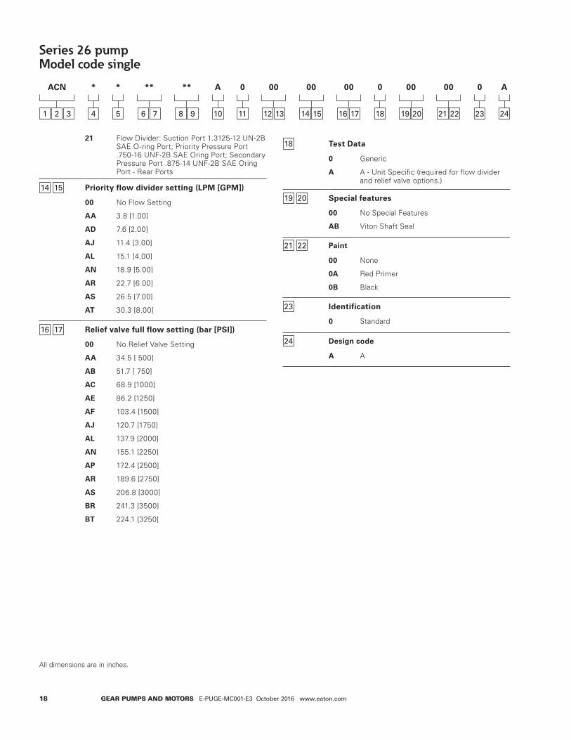
Series 26 pumpModel code single
All dimensions are in inches .
Series 26 gear pumps can be ordered by using the following model code .
A twenty-four digit coding system has been designed to identify the features presently available on single gear pumps . The characters and their relative positions within the code identify specific features .
Use the model code matrix as an aid when assembling the model code for the pump with the features you desire . It may be helpful to photocopy the matrix and write the numbers and letters into the boxes as you select features .
All twenty-four digits of the code must be submitted when ordering .
*
4
ACN
1 2 3
**
6 7
**
8 9
00
12 13
00
14 15
00
16 17
00
19 20
00
21 22
*
5
A
10
0
11
0
18
0
23
A
24
1 2 3 26 Series
ACN Gear pump - single unit
4 Unit type
A PlainB Flow divider with/without relief valve (pos .
14-15)
C Relief valve (pos . 16-17)
5 Input rotation (viewed from input shaft end)
L Left-hand rotation CCWR Right-hand rotation CW
6 7 Displacement (cm³/r [in³/r])
01 6 .6 [ .40]
02 8 .2 [ .50]
03 9 .5 [ .58]
04 10 .8 [ .66]
05 13 .8 [ .84]
06 16 .7 [1 .02]
07 19 .7 [1 .20]
08 22 .5 [1 .37]
09 24 .3 [1 .48]
10 25 .2 [1 .54]
11 27 .7 [1 .69]
12 29 .0 [1 .77]
13 30 .6 [1 .87]
8 9 Input shaft
AA 5/8 Inch dia . 9 Tooth spline 16/32 pitch shaft extension 31 .8 [1 .25]
AB 3/4 Inch dia . 11 Tooth spline 16/32 pitch shaft extension 31 .8 [1 .25]
AC 3/4 Inch dia . Straight keyed, keyway 4 .8 X 25 .4 [ .19 X 1 .00] Shaft extension 31 .8 [1 .25]
AD 5/8 Inch dia . Straight keyed, keyway 4 .1 X 18 .3 [ .16 X .72] Shaft extension 31 .8 [1 .25]
10 Mounting features
A SAE 2-bolt a flange, series 82-2
B SAE 2-bolt A flange with thru drain
C SAE 2-bolt b flange, series 101-2
D European 4-bolt
11 Auxiliary mounting features
0 No rear mounting
C (2-Bolt AA) SAE flange series 50-2, with 9 tooth internal spline 20/40 pitch, accepts 25 .4 [1 .00] Shaft extension
12 13 Ports, sizes and location- backplate
01 Plain: suction port 1 .3125-12 UN-2B SAE O-ring port; pressure port .875-14 UNF-2B SAE O-ring port - side sports
02 Plain: suction port 1 .3125-12 UN-2B SAE O-ring port; pressure port .875-14 UNF-2B SAE O-ring port - rear ports
03 Plain: suction port 1 .0625-12 UN-2B SAE O-ring port; pressure port .875-14 UNF-2B SAE O-ring port accepts fittings per SAE J1926 - side ports
04 Plain: suction port 1 .0625-12 UN-2B SAE O-ring port; pressure port .875-14 UNF-2B SAE O-ring port accepts fittings per SAE J1926 -rear ports
08 Plain thru shaft: suction port 1 .0625-12 UN-2B SAE Oring port; pressure port .875- 14 UNF-2B SAE O-ring port - side ports
15 Relief valve: suction port 1 .0625-12 UN-2B SAE O-ring port; pressure port .875-14 UNF-2B SAE O-ring port - side ports; drain port .875-14 UNF- 2B SAE O-ring port
16 Relief valve: suction port 1 .0625-12 UN-2B SAE O-ring port; pressure port .875-14 UNF-2B SAE O-ring port - rear ports; drain port .875-14 UNF- 2B SAE O-ring port
20 Flow divider: suction port 1 .3125-12 UN-2B SAE O-ring port; priority pressure port .750-16 UNF-2B SAE Oring port; secondary pressure port .875-14 UNF-2B SAE Oring Port - Side Ports
18 GEAR PUMPS AND MOTORS E-PUGE-MC001-E3 October 2016 www.eaton.com
Series 26 pumpModel code single
All dimensions are in inches .
*
4
ACN
1 2 3
**
6 7
**
8 9
00
12 13
00
14 15
00
16 17
00
19 20
00
21 22
*
5
A
10
0
11
0
18
0
23
A
24
21 Flow Divider: Suction Port 1 .3125-12 UN-2B SAE O-ring Port; Priority Pressure Port .750-16 UNF-2B SAE Oring Port; Secondary Pressure Port .875-14 UNF-2B SAE Oring Port - Rear Ports
14 15 Priority flow divider setting (LPM [GPM])
00 No Flow Setting
AA 3 .8 [1 .00]
AD 7 .6 [2 .00]
AJ 11 .4 [3 .00]
AL 15 .1 [4 .00]
AN 18 .9 [5 .00]
AR 22 .7 [6 .00]
AS 26 .5 [7 .00]
AT 30 .3 [8 .00]
16 17 Relief valve full flow setting (bar [PSI])
00 No Relief Valve Setting
AA 34 .5 [ 500]
AB 51 .7 [ 750]
AC 68 .9 [1000]
AE 86 .2 [1250]
AF 103 .4 [1500]
AJ 120 .7 [1750]
AL 137 .9 [2000]
AN 155 .1 [2250]
AP 172 .4 [2500]
AR 189 .6 [2750]
AS 206 .8 [3000]
BR 241 .3 [3500]
BT 224 .1 [3250]
18 Test Data
0 Generic
A A - Unit Specific (required for flow divider and relief valve options .)
19 20 Special features
00 No Special Features
AB Viton Shaft Seal
21 22 Paint
00 None
0A Red Primer
0B Black
23 Identification
0 Standard
24 Design code
A A

19GEAR PUMPS AND MOTORS E-PUGE-MC001-E3 October 2016 www.eaton.com
Series 26 pumpModel code multiple
All dimensions are in inches .
Series 26 Gear Pumps can be ordered by using the following Model Code .
A thirty-two digit coding system has been designed to identify the features presently available on Multiple gear
pumps . The characters and their relative positions within the code identify specific features . Use the Model Code Matrix as an aid when assembling the model code for the pump with the features you desire . It may be helpful
to photocopy the matrix and write the numbers and letters into the boxes as you select features .
All thirty-two digits of the code must be submitted when ordering .
*
4
ACM
1 2 3
**
6 7
**
8 9
**
12 13
**
10 11
**
14 15
**
16 17
**
18 19
00
20 21
00
22 23
00
27 28
00
29 30
*
5
A
24
0
31
0
25
0
26
B
32
1 2 3 26 Series
ACM Gear Pump - Multiple Unit
4 Unit type
A PlainB Flow Divider with/without Relief Valve (Pos .
20-21)
C Relief Valve
5 Input rotation (viewed from input shaft end)
L Left-hand Rotation CCWR Right-hand Rotation CW
6 7 Displacement - front (cm³/r [in³/r])
01 6 .6 [ .40]02 8 .2 [ .50]03 9 .5 [ .58]04 10 .8 [ .66]05 13 .8 [ .84]06 16 .7 [1 .02]07 19 .7 [1 .20]08 22 .5 [1 .37]09 24 .3 [1 .48]10 25 .2 [1 .54]11 27 .7 [1 .69]12 29 .0 [1 .77]13 30 .6 [1 .87]
8 9 Displacement - Ctr. triple only (cm³/r [in³/r])
01 6 .6 [ .40]02 8 .2 [ .50]03 9 .5 [ .58]04 10 .8 [ .66]05 13 .8 [ .84]06 16 .7 [1 .02]07 19 .7 [1 .20]08 22 .5 [1 .37]09 24 .3 [1 .48]10 25 .2 [1 .54]11 27 .7 [1 .69]12 29 .0 [1 .77]13 30 .6 [1 .87]99 No Center Displacement
14 15 Front adapter ports
01 Suction Port 1-5/8–12 UN-2B SAE O-ring Port; Pressure Port 7/8–14 UNF-2B SAE O-ring Port
05 Suction Port 1-5/16–12 UN-2B SAE O-ring Port; Pressure Port 7/8–14 UNF-2B SAE O-ring Port
16 17 Ports - rear adapter (triple units)
00 No Rear Adaptor01 Suction Port 1-5/8–12 UN-2B SAE O-ring
Port; Pressure Port 7/8–14 UNF-2B SAE O-ring Port
05 05 = Suction Port 1-5/16–12 UN-2B SAE O-ring Port; Pressure Port 7/8–14 UNF-2B SAE O-ring Port
10 11 Displacement - front (cm³/r [in³/r])
01 6 .6 [ .40]02 8 .2 [ .50]03 9 .5 [ .58]04 10 .8 [ .66]05 13 .8 [ .84]06 16 .7 [1 .02]07 19 .7 [1 .20]08 22 .5 [1 .37]09 24 .3 [1 .48]10 25 .2 [1 .54]11 27 .7 [1 .69]12 29 .0 [1 .77]13 30 .6 [1 .87]
12 13 Input shaft
AA 5/8 Inch Dia . 9 Tooth Spline 16/32 Pitch Shaft Extension 31 .8 [1 .25]
AB 3/4 Inch Dia . 11 Tooth Spline 16/32 Pitch Shaft Extension 31 .8 [1 .25]
AC 3/4 Inch Dia . Straight Keyed, Keyway 4 .8 x 25 .4 [ .19 x 1 .00] Shaft Extension 31 .8 [1 .25]
AD 5/8 Inch Dia . Straight Keyed, Keyway 4 .1 X 18 .3 [ .16 X .72] Shaft Extension 31 .8 [1 .25]

20 GEAR PUMPS AND MOTORS E-PUGE-MC001-E3 October 2016 www.eaton.com
Series 26 pumpModel code multiple
All dimensions are in inches .
*
4
ACM
1 2 3
**
6 7
**
8 9
**
12 13
**
10 11
**
14 15
**
16 17
**
18 19
00
20 21
00
22 23
00
27 28
00
29 30
*
5
A
24
0
31
0
25
0
26
B
32
18 19 Ports, sizes and location- backplate
01 Plain: Suction Port 1-5/16–12 UN-2B SAE O-ring Port Size; Pressure Port 7/8–14 UNF-2B SAE O-ring Port–Side Ports
02 Plain: Suction Port 1-5/16–12 UN-2B SAE O-ring Port Size; Pressure Port 7/8–14 UNF-2B SAE O-ring Port–Rear Ports
03 Plain: Suction Port 1-1/16–12 UN-2B SAE O-ring Port Size; Pressure Port 7/8–14 UNF-2B SAE O-ring Port–Side Ports
04 Plain: Suction Port 1-1/16–12 UN-2B SAE O-ring Port Size; Pressure Port 7/8–14 UNF-2B SAE O-ring Port–Rear Ports
08 Plain Tandem: Suction Port 1 .0625-12 UN-2B SAE Oring Port; Pressure Port .875- 14 UNF-2B SAE O-ring Port - Side Ports
14 Plain: Suction Port 1-5/16–12 UN-2B SAE O-ring Port Size–(Plugged); Pressure Port 7/8–14 UNF-2B SAE O-ring Port–Side Ports, used with position 14 and 15–01 and 16 and 17–10
17 Plain: Suction Port 1-5/16–12 UN-2B SAE O-ringPort Size–(Plugged); Pressure Port 7/8–14 UNF-2B SAE O-ring Port–Rear Ports, used with position 14 and 15–01 and 16 and 17–01
18 Plain Tandem: Suction Port 1 .0625-12 UN-2B SAE Oring Port (Plugged); Pressure Port .875-14 UNF-2B SAE Oring Port - Side Ports
19 Plain: Suction Port 1 .3125-12 UN-2B SAE O-ring Port (Plugged); Pressure Port 1 .0625-12 UN-2B SAE O-ring Port - Side Ports
20 Relief Valve: Suction Port 1 .0625-12 UN-2B SAE O-ring Port; Pressure Port .875-14 UNF-2B SAE O-ring Port - SIDE Ports; DRAIN Port .875- 14 UNF-2B SAE O-ring Port
21 Relief Valve: Suction Port 1 .0625-12 UN-2B SAE O-ring Port; Pressure Port .875-14 UNF-2B SAE O-ring Port - Rear Ports; DRAIN Port .875-14 UNF-2B SAE O-ring Port - TOP Port
20 21 Priority flow divider setting (LPM [GPM])
00 No Flow SettingAA 3 .8 [1 .00]AD 7 .6 [2 .00]AJ 11 .4 [3 .00]AL 15 .1 [4 .00]AN 18 .9 [5 .00]AR 22 .7 [6 .00]AS 26 .5 [7 .00]AT 30 .3 [8 .00]
22 23 Relief valve full flow setting (bar [PSI])
00 No Relief Valve SettingAA 34 .5 [500]AB 51 .7 [750]AC 68 .9 [1000]AE 86 .2 [1250]AF 103 .4 [1500]AJ 120 .7 [1750]AL 137 .9 [2000]AN 155 .1 [2250]AP 172 .4 [2500]AR 189 .6 [2750]AS 206 .8 [3000]
27 Flow Divider: Suction Port 1 .3125-12 UN-2B SAE Oring Port; Priority Pressure Port .750-16 UNF-2B SAE Oring Port; Secondary Pressure Port .875-14 UNF-2B SAE Oring Port - SIDE Ports
28 Flow Divider: Suction Port 1 .3125-12 UN-2B SAE Oring Port; Priority Pressure Port .750-16 UNF-2B SAE Oring Port; Secondary Pressure Port .875-14 UNF-2B SAE Oring Port - Rear Ports
29 Flow Divider: Suction Port 1 .0625-12 UN-2B SAE Oring Port; Priority Pressure Port .5625-18 UNF-2B SAE Oring Port; Secondary Pressure Port .875-14 UNF-2B SAE Oring Port - SIDE Ports
Consult your Eaton representative when requiring common inlet option.

21GEAR PUMPS AND MOTORS E-PUGE-MC001-E3 October 2016 www.eaton.com
Series 26 pumpModel code multiple
All dimensions are in inches .
*
4
ACM
1 2 3
**
6 7
**
8 9
**
12 13
**
10 11
**
14 15
**
16 17
**
18 19
00
20 21
00
22 23
00
27 28
00
29 30
*
5
A
24
0
31
0
25
0
26
B
32
24 Mounting features (front)
A (2-Bolt A) SAE Flange, Series 82-3
C (2-Bolt B) SAE Flange Series 82 .3
G (4-Bolt) European
25 Auxiliary mounting features
0 No Rear Mounting
C (2-Bolt AA) SAE Flange Series 50-2, with 9 Tooth Internal Spline 20/40 Pitch, Accepts 25 .4 [1 .00] Shaft Extension
26 Test data
0 Generic
A Unit Specific (required for flow divider and relief valve options .)
27 28 Special features
00 No Special Features
AB Viton Shaft Seal
29 30 Paint
00 None
0A Red Primer
0B Black
31 Identification
0 Standard
32 Design code
B B

22 GEAR PUMPS AND MOTORS E-PUGE-MC001-E3 October 2016 www.eaton.com
Series 26 pumpSide-load applications
Maximum allowable operating pressures
0.40/0.50 CID 0.58/0.66 CID
.84 CID 1.02 CID
Pulley Ø 2 4 6 8 10 12
Gear pitch Ø 1 2 3 4 5 6
Y Dimension
2.0” 3000 3000 3000 3000 3000 30001.5” 3000 3000 3000 3000 3000 30001.0” 3000 3000 3000 3000 3000 30000.5” 3000 3000 3000 3000 3000 30000” 3000 3000 3000 3000 3000 3000
Pulley Ø 2 4 6 8 10 12
Gear pitch Ø 1 2 3 4 5 6
Y Dimension
2.0” 2250 3000 3000 3000 3000 30001.5” 2250 3000 3000 3000 3000 30001.0” 2500 3000 3000 3000 3000 30000.5” 2500 3000 3000 3000 3000 30000” 2750 3000 3000 3000 3000 3000
Pulley Ø 2 4 6 8 10 12
Gear pitch Ø 1 2 3 4 5 6
Y Dimension
2.0” 1750 2500 3000 3000 3000 30001.5” 1750 2750 3000 3000 3000 30001.0” 2000 2750 3000 3000 3000 30000.5” 2000 3000 3000 3000 3000 30000” 2250 3000 3000 3000 3000 3000
Pulley Ø 2 4 6 8 10 12
Gear pitch Ø 1 2 3 4 5 6
Y Dimension
2.0” 1250 2000 2250 2500 2750 30001.5” 1250 2000 2500 2750 3000 30001.0” 1250 2000 2500 2750 3000 30000.5” 1500 2250 2500 2750 3000 30000” 1500 2250 2750 3000 3000 3000
Ideal positions shown .Side load is acceptable within 90° of either side of the ideal position . Charts are based on 100% slack side tension . Max . speed per catalog . Max . operating pressure shown .
Gear drive
0°
Pumpinlet
45°
CW Rotation
Gear drive
0°
45°
Pumpinlet
CCW Rotation
Y
PitchDia.
0°Pumpinlet
50°
CW Rotation
Pulley drive
50°
0°Pumpinlet
CCW Rotation
Pulley drive

23GEAR PUMPS AND MOTORS E-PUGE-MC001-E3 October 2016 www.eaton.com
Series 26 pumpSide-load applications
Maximum allowable operating pressures
.1.48/1.54 CID
1.20 CID
1.69 CID
1.37 CID
1.77/1.87 CID
Pulley Ø 2 4 6 8 10 12
Gear pitch Ø 1 2 3 4 5 6
Y Dimension
2.0” N/R N/R 1250 1500 1750 20001.5” N/R 1250 1500 1750 1750 20001.0” N/R 1250 1500 1750 2000 20000.5” N/R 1250 1500 1750 2000 20000” N/R 1500 1750 2000 2000 2250
Pulley Ø 2 4 6 8 10 12
Gear pitch Ø 1 2 3 4 5 6
Y Dimension
2.0” N/R 1500 2000 2250 2250 25001.5” N/R 1500 2000 2250 2500 25001.0” N/R 1750 2000 2250 2500 25000.5” 1250 1750 2250 2250 2500 27500” 1250 1750 2250 2500 2750 3000
Pulley Ø 2 4 6 8 10 12
Gear pitch Ø 1 2 3 4 5 6
Y Dimension
2.0” N/R N/R 1250 1500 1500 17501.5” N/R N/R 1250 1500 1500 17501.0” N/R N/R 1250 1500 1750 17500.5” N/R 1250 1250 1500 1750 17500” N/R 1250 1500 1750 1750 2000
Pulley Ø 2 4 6 8 10 12
Gear pitch Ø 1 2 3 4 5 6
Y Dimension
2.0” N/R 1250 1750 2000 2000 22501.5” N/R 1250 1750 2000 2000 22501.0” N/R 1500 1750 2000 2250 22500.5” N/R 1500 1750 2000 2250 22500” N/R 1500 1750 2000 2250 2500
Pulley Ø 2 4 6 8 10 12
Gear pitch Ø 1 2 3 4 5 6
Y Dimension
2.0” N/R N/R N/R 1250 1500 15001.5” N/R N/R 1250 1250 1500 15001.0” N/R N/R 1250 1250 1500 15000.5” N/R N/R 1250 1500 1500 17500” N/R N/R 1250 1500 1750 1750
Ideal positions shown .Side load is acceptable within 90° of either side of the ideal position . Charts are based on 100% slack side tension . Max . speed per catalog . Max . operating pressure shown .
Y
PitchDia.

24 GEAR PUMPS AND MOTORS E-PUGE-MC001-E3 October 2016 www.eaton.com
Series 26 pumpLoad sensing priority valve
The Load Sensing Priority Valve is used with the open loop load sense systems that are typically used in steering and braking circuits . The load sense gear pump provides metered priority flow (CF)on demand .
The excess flow (EF)is available for auxiliary circuits . The response time was selected to insure that the operator will not sense a delay or steering “kick”during transient conditions .
Valve specifications
Rated Pressure 207 BAR (3000PSI)Rated Inlet Flow 108 L/m (28GPM)Maximum Controlled Flow (CF) 33 L/m(8.5 GPM)Bias Pressure Dynamic - 10 bar (150 PSI) Std.
Static - 6.9 bar (100 PSI) Std.Relief Pressure 34.5-207 bar (500-3000 PSI)Response Time 70 msec. max. (std. bias spring)
Pump specifications
Displacements9 Available: 8.2cm³r [.50 in³/r] thru 30.6 cm³/r [1.87in³/r]
Mounting SAE 2-Bolt A MountSAE 2-Bolt B Mount4-Bolt European Mount (80mm Pilot)

25GEAR PUMPS AND MOTORS E-PUGE-MC001-E3 October 2016 www.eaton.com
Series 26 motorGeneral specifications
Ordering information
Catalog assemblies cross reference
Standard catalog assemblies are built from high production parts and are the most economical pump assemblies available in this series . The standard assembly order number is a preassigned part number and may be used to order the specific standard assembly (see page 27) .
† Continuous - motor may be run continuously at these ratings .†† Intermittent - intermittent operation, 10% of every minute .* 31 .8 cm³/rev . [1 .94 in³/rev .] displacement max . continuous pressure is 190 bar [2750 PSI] .** 31 .8 cm³/rev . [1 .94 in³/rev .] displacement max . intermittent pressure is 224 bar [3250 PSI] . For side load limits
consult your Eaton representative .
Rotation Bi-RotationMounting Flange SAE A 2 BoltMax. Continuous Pressure† 210 bar [3000 PSI]*Max. Intermittent Pressure†† 240 bar [3500 PSI]**Minimum Speed at Continuous Pressure 750 RPMMaximum Rotating Torque at 0 Pressure 4 Nm [36 lb-in]Maximum Continuous Operating Temperature 105°C [220°F]Minimum Continuous Oil Viscocity 5.7 cSt [45 SUS]Minimum Operating Temperature -29°C [-20°F]Maximum Inlet Vacuum at Operating Condition 0,8 bar Abs. [11.6 psi Abs.]Maximum Thrust Load 50 lbs.Maximum Seal Pressure 150 PSI, 200 PSI @ 1500 RPM
Displacement cm³/r [in³/r]7,0[.43]
8,8[.54]
10,1[.62]
11,6[.71]
14,5[.88]
17,3[1.06]
20,3[1.24]
Max. Intermittent Pressure bar [PSI] 241[3495]
241[3495]
241[3495]
241[3495]
241[3495]
241[3495]
241[3495]
Rated Speed (RPM) 3600 3600 3600 3600 3600 3200 3200Minimum Output Flow at ContinuousRated Speed and Pressure LPM [GPM]
22,2[5.9]
27,9[7.4]
32,0[8.5]
36,7[9.7]
48,0[12.7]
50,9[13.5]
59,8[15.8]
The performance data in the table above and the following graphs was collected using a mineral base oil with a viscosity of 133 SUS at 49°C [120°F] .
Displacement cm³/r [in³/r]23,1[1.41]
25,2[1.54]
26,0[1.59]
28,8[1.76]
30,3[1.85]
31,7[1.93]
Max. Intermittent Pressure bar [PSI] 241[3495]
241[3495]
241[3495]
241[3495]
234[3393]
224[3248]
Rated Speed (RPM) 3000 3000 3000 3000 3000 3000Minimum Output Flow at ContinuousRated Speed and Pressure LPM [GPM]
63,8[16.8]
69,6[18.4]
71,8[19.0]
79,5[21.0]
83,6[22.1]
87,5[23.1]

26 GEAR PUMPS AND MOTORS E-PUGE-MC001-E3 October 2016 www.eaton.com
92,5 [3.64]46,2
[1.82]
21,1 [.83]
Driveshaft
42,2 [1.66]
Work Port
Work Port(optional)
Case Drain Po rt - Bottom(Plugged fo r Internal Drain Option)
WorkPort
Work Port(optional)
72,0[2.83]
WorkPort
Work Port(optional)
35,7[1.41]
Case Drain Po rt - Top(Plugged fo r InternalDrain Option)
Driveshaft
Work Port
Work Port(optional)
92,5 [3.64]46,2
[1.82]
21,1 [.83]42,2 [1.66]
18 [.71]
Dim D Max2X Dim C
2X Dim A
14,2[.56]
For shaft con�guration, seeseparate shaft drawing.
For front mounting con�guration, see sepa ratefront mounting drawing.
Dim B
Series 26 Motor Performance Data
Bottom Drain
Top Drain
Front mount: 2 bolt SAE A and B
Displacement Dim A Dim B Dim C Dim D
cm³/r [in³/r] mm [in] mm [in] mm [in] mm [in]
7.0 [.43] 69.2 [2.72] 67.9 [2.67] 89.0 [3.50] 96.6 [3.80]8.8 [.54] 71.1 [2.80] 69.8 [2.75] 90.9 [3.58] 98.5 [3.88]10.2 [.62] 72.6 [2.86] 71.3 [2.81] 92.4 [3.64] 100.0 [3.94]11.6 [.71] 74.3 [2.93] 73.0 [2.88] 94.1 [3.71] 101.7 [4.01]12.5 [.76] 75.2 [2.96] 74.0 [2.91] 95.1 [3.74] 102.7 [4.04]14.6 [.89] 77.5 [3.05] 76.2 [3.00] 97.3 [3.83] 104.9 [4.13]17.4 [1.06] 80.7 [3.18] 79.4 [3.13] 100.5 [3.96] 108.1 [4.26]20.3 [1.24] 83.9 [3.30] 82.6 [3.25] 103.7 [4.08] 111.3 [4.38]23.1 [1.41] 87.1 [3.43] 85.8 [3.38] 106.9 [4.21] 114.5 [4.51]26.1 [1.59] 90.3 [3.56] 89.0 [3.51] 110.1 [4.34] 117.7 [4.64]28.8 [1.76] 93.5 [3.68] 92.2 [3.63] 113.3 [4.46] 120.9 [4.76]31.8 [1.94] 96.7 [3.81] 95.4 [3.76] 116.5 [4.59] 124.1 [4.89]
For front mountingcon�guration, see separatefrontmounting drawing.

27GEAR PUMPS AND MOTORS E-PUGE-MC001-E3 October 2016 www.eaton.com
Series 26 motor Model code - single
All dimensions are in inches .
Series 26 Gear Pumps can be ordered by using the following Model Code .
A twenty-four digit coding system has been designed to identify the features presently available on Single gear pumps . The characters and their relative positions within the code identify specific features .
Use the Model Code Matrix as an aid when assembling the model code for the pump with the features you desire . It may be helpful to photocopy the matrix and write the numbers and letters into the boxes as you select features .
All twenty-four digits of the code must be submitted when ordering .
*
4
ADM
1 2 3
**
6 7
**
8 9
00
11 12
00
13 14
00
16 17
00
19 20
00
21 22
*
5
A
10
0
15
0
18
0
23
A
24
1 2 3 26 Series
ADM Gear Motor
4 Unit type
A Plain
5 Output rotation
D Bi-DirectionalL Left-hand Rotation CCWR Right-hand Rotation CW
6 7 Displacement (cm³/r [in³/r])
01 7 .0 [ .43]02 8 .8 [ .54]03 10 .2 [ .62]04 11 .6 [ .71]05 14 .6 [ .89]06 17 .4 [1 .06]07 17 .4 [1 .06]08 23 .1 [1 .41]09 25 .2 [1 .54]10 26 .1 [1 .59]11 28 .8 [1 .76]12 30 .3 [1 .85]13 31 .8 [1 .94]
8 9 Output shaft
AA 9 Tooth Spline 16/32 Spline, Min . Full Spline 22 .4 [ .88], Shaft Extension 31 .8 [1 .25]
AB 11 Tooth Spline 16/32 Spline, Min . Full Spline 22 .4 [ .88], Shaft Extension 31 .8 [1 .25]
AC Straight Shaft Dia 19 .05 [ .750], Keyway 4 .8 x 25 .4 [ .19 x 1 .00], Shaft Extension 31 .8 [1 .25] (Key Included)
AD Straight Shaft Dia 15 .88 [ .625], Keyway 4 .1 x 18 .3 [ .16 x .72], Shaft Extension 31 .8 1 .25] (Key Included)
AJ Dia 15 .88 [ .625], Taper .125:1, .500-20 UNF-2A, Keyway 4 .1 x 17 .5 [ .16 x .69], Shaft Extension 43 .7 [1 .72] (Key Included)
10 Mounting features
A 2-Bolt A - SAE Flange Series 82-2
11 12 Ports, sizes and location- backplate
01 Inlet Port 1 .0625-12 UN-2B SAE O-Ring Port; Outlet Port 1 .0625-12 UN-2B SAE O-Ring Port - Side Ports
02 Inlet Port 1 .0625-12 UN-2B SAE O-Ring Port; Outlet Port 1 .0625-12 UN-2B SAE O-Ring Port - Rear Ports
03 Inlet Port .875-14 UN-2B SAE O-Ring Port; Outlet Port .875-14 UN-2B SAE O-Ring Port - Side Ports
04 Inlet Port .875-14 UN-2B SAE O-Ring Port; Outlet Port .875-14 UN-2B SAE O-Ring Port - Rear Ports
13 14 Case drain
00 No Case DrainAA .5625-18 UNF-2B SAE O-Ring Port -
BottomAB .5625-18 UNF-2B SAE O-Ring Port - TopAC Internal with Bi-Directional Checks,
.5625-18 UNF-2B SAE O-Ring Port - Plugged
AD .5625-18 UNF-2B SAE O-Ring Port - Bottom-Plugged
AE .5625-18 UNF-2B SAE O-Ring Port - Top-Plugged
15 Relief valve type
0 No Relief ValveC Cross-over
16 17 Relief valve setting bar [lbf/in2]
00 No Relief Valve SettingAA 117 .2 [1700]AB 141 .3 [2050]AC 31 .0 [450]
18 Test data
0 Generic
A Unit Specific (Used with Relief Valve)

28 GEAR PUMPS AND MOTORS E-PUGE-MC001-E3 October 2016 www.eaton.com
Series 26 motor Model code - single
All dimensions are in inches .
*
4
ADM
1 2 3
**
6 7
**
8 9
00
11 12
00
13 14
00
16 17
00
19 20
00
21 22
*
5
A
10
0
15
0
18
0
23
A
24
19 20 Special features
00 No Special Features
21 22 Paint
00 None
0A Primer per Spec 209-13A
0B Black per Spec 209-13B
23 Identification
0 Standard
24 Design code
A A

29GEAR PUMPS AND MOTORS E-PUGE-MC001-E3 October 2016 www.eaton.com
Series L2 pumpGeneral specifications and performance data
Rotation CCW or CWMounting Flange SAE 2 Bolt BMaximum Continuous† Pressure 248 bar [3600 PSI]*Maximum Intermittent†† Pressure 276 bar [4000 PSI]**Minimum Speed at Continuous Pressure 750 RPMMaximum Continuous Inlet Temperature 107°C [225°F]Minimum Operating Temperature -29°C [-20°F]Maximum Inlet Vacuum at 82°C [180°F] and Rated Speed
6.0 In. Hg
The performance data in the table above and the following graphs was collected using a mineral base oil with a viscosity of 133 SUS at 49° C [120° F] . The fol-lowing performance graphs are representative of the series .† Continuous - pump may be run continuously at these ratings .†† Intermittent - Intermittent operation, 10% of every minute .
Model 25500 25501 25502 25503 25504 25505 25506 25507 25508
Displacement cm³/r [in³/r] 21.3[1.30]
25.4[1.55]
29.2[1.78]
33.6[2.05]
38.2[2.33]
42.8[2.61]
46.7[2.85]
51.1[3.12]
55.2[3.37]
Max. Continuous† Pressure bar [PSI] 248[3600]
248[3600]
248[3600]
248[3600]
248[3600]
248[3600]
224[3250]
207[3000]
190[2750]
Max. Intermittent†† Pressure bar [PSI] 276[4000]
276[4000]
276[4000]
276[4000]
276[4000]
276[4000]
252[3650]
234[3400]
217[3150]
Rated Speed (RPM) 3500 3000 3000 2750 2750 2500 2500 2500 2250Minimum Output Flow at 207 bar [3000 PSI]and Rated Speed LPM [GPM]
61,3[16.2]
64,7[17.1]
78,0[20.6]
83,3[22.0]
94,6[25.0]
96,1[25.4]
105,2[27.8]
115,1[30.4]
112,0[29.6]
Ordering information
Standard catalog assemblies
Standard Catalog Assemblies are built from high quality production parts and are the most economical pumps available in this series . Dimensions and order numbers for Standard Catalog Assemblies are given on pages 29-30 .
Optional configurations
Besides the Standard Catalog Assemblies, the L2 Series has several optional features . Flow divider and tandem backplates are available . Multiple gear pumps can also be built . If a variation from the Standard Catalog Assemblies is required, use the model codes on pages 35-36 . .
† Continuous - pump may be run continuously at these ratings .†† Intermittent - Intermittent operation, 10% of every minute .For side load limits consult your Eaton representative .* 46 .7 [2 .85] displacement maximum continuous pressure is 224 bar [3250 PSI] 51 .1 [3 .12] displacement maximum continuous pressure is 207 bar [3000 PSI] 55 .2 [3 .37] displacement maximum continuous pressure is 190 bar [2750 PSI]** 46 .7 [2 .85] displacement maximum intermittent pressure is 252 bar [3650 PSI] 51 .1 [3 .12] displacement maximum intermittent pressure is 234 bar [3400 PSI] 55 .2 [3 .37] displacement maximum intermittent pressure is 217 bar [3150 PSI]

30 GEAR PUMPS AND MOTORS E-PUGE-MC001-E3 October 2016 www.eaton.com
Series L2 pumpPerformance data charts
Output power vs speed
Ou
tpu
t fl
ow a
t 69
bar
[10
00 P
SI]
(L
PM
[G
PM
]
Input speed (RPM)
0
30[8]
60[16]
90[24]
120[32]
350030002500200015001000500 750
Input Speed (RPM)
21.3 [1.30]
25.4 [1.55] 29.2 [1.78]
33.6 [2.05] 38.2 [2.33]
42.8 [2.61] 46.7 [2.85]
51.1 [3.12] 55.2 [3.37]
Out
put
Flow
at
69 B
ar [
1000
PS
I]
(LP
M [G
PM
]
Input speed (RPM)
Ou
tpu
t Fl
ow a
t 20
7 B
ar [
3000
PS
I] (
LPM
[G
PM
]
21.3 [1.30]
25.4 [1.55] 29.2 [1.78]
33.6 [2.05]
38.2 [2.33] 42.8 [2.61] 46.7 [2.85] 51.1 [3.12] 55.2 [3.37]
350030002500200015001000500 750 0
30[8]
60[16]
90[24]
120[32]
Displacementcm3/r [in 3/r]
Out
put
Flow
at
207
Bar
[30
00 P
SI]
(LP
M [G
PM
]

31GEAR PUMPS AND MOTORS E-PUGE-MC001-E3 October 2016 www.eaton.com
Series L2 pump Performance data charts
Input Power vs Speed
The performance data show in the graphs are representative of this series . Tests were performed per SAE specifications using min-eral base oil with a viscosity of 133 SUS at 49° C [120° F] .
Inp
ut
pow
er
at 6
9 b
ar [
1000
P
SI]
(kW
[H
P])
Input speed (RPM)
0
5[7]
10[13]
15[20]
21.3 [1.30]
25.4 [1.55] 29.2 [1.78]
33.6 [2.05] 38.2 [2.33]
42.8 [2.61] 46.7 [2.85]
51.1 [3.12] 55.2 [3.37]
350030002500200015001000500 750
Input Speed (RPM)
Inpu
t P
ower
at
69 B
ar [
1000
PS
I] (k
W [
HP
]) In
pu
t p
ower
at
207
bar
[30
00
PS
I] (
kW [
HP
])
Input speed (RPM)
The performance data show in the graphs are representative of this series. Tests were performedper SAE speci�cations using mineral base oil with a viscosity of 133 SUS at 49° C [120° F].
0
10
[13]
20
[27]
30
[40]
40
[54]
50
[67]
21.3 [1.30]
25.4 [1.55]
29.2 [1.78] 33.6 [2.05] 38.2 [2.33]
42.8 [2.61] 46.7 [2.85]
51.1 [3.12] 55.2 [3.37]
350030002500200015001000500 750
Input Speed (RPM)
Displacementcm3/r [in 3/r]
Inpu
t P
ower
at
207
Bar
[30
00 P
SI]
(kW
[H
P])

32 GEAR PUMPS AND MOTORS E-PUGE-MC001-E3 October 2016 www.eaton.com
Series L2 pumpStandard catalog assemblies - dimensions
All dimensions are in mm [in] .
* Multiple pump input torque limitations:
The total torque for multiple pump displacements and pressure combinations cannot exceed the maximum input torque rating of the shaft . The proper formula is Pressure times Displacement divided by 6 .28 .
Left hand rotation shown
† For split flange porting subtract .8 [ .03], available in side porting only
7/8 inch straight key
Maximum Input Torque†† 170 Nm [1500 lb-in]
7/8 inch 13 tooth spline
Maximum Input Torque†† 209 Nm [1850 lb-in]
7/8 inch 41 tooth spline
Maximum Input Torque†† 316 Nm [2800 lb-in]
Model 25500 25501 25502 25503 25504 25505 25506 25507 25508
Displacement (cm³/r [in³/r]) 21.3 [1.30] 25.4 [1.55] 29.2 [1.78] 33.6 [2.05] 38.2 [2.33] 42.8 [2.61] 46.7 [2.85] 51.1 [3.12] 55.2 [3.37]Dimension A (mm [in.]) 84.8 [3.34] 88.2 [3.47] 91.7 [3.61] 95.1 [3.75] 98.6 [3.88] 102.0 [4.02] 105.3 [4.14] 109.0 [4.29] 112.4 [4.43]Dimension B (mm [in.]) 117.3 [4.62] 120.8 [4.75] 124.2 [4.89] 127.7 [5.03] 131.1 [5.16] 134.6 [5.30] 137.8 [5.42] 141.5 [5.57] 145.0 [5.71]
Dia.22.222±0.003[.8749±.0001
[.978±.004]4.1[.16]
[.97]
6.30 +0.05-0.03
.248+0.02-0.01][
7/8 inch straight keyMaximum input torque††170 Nm [1500 lb-in]
13 Tooth 16/32 DP 30° InvoluteFlat root class 1 side �t splineSAE J498b
41.1[1.62]
7/8 Inch 13 Tooth Spline
Maximum input torque††209 Nm [1850 lb-in]
24.9 [.98] 13 [.51] Min full spline
41 Tooth 48/96 DP 45°Involute �llet root class 1side �t spline
7/8 Inch 41 Tooth SplineMaximum Input Torque††316 Nm [2800 lb-in]
IN
OU
T
59.9[2.36]
146[5.75]
177.8[7.00]
104.4[4.11]
2X Dia. 14.5 ± 0.13 [.572 ± .005]
81.8 †
[3.22]75.4 †
[2.97]
Suctionportsideporting†
Left hand rotation shown
27.7[1.09]
27.7[1.09]
See shaftdrawing
Dim B
2X Dim A
Driveshaftcenterline
22.4[.88]
Pressure portside porting†
Dia.101.57 ± 0.03 [3.999 ± .001]
17.5[.69] 9.7
[.38]Pressure portrear portingSuction
portrearporting
† For split �ange porting subtract .8 [.03], available in side porting only
C L
CL

33GEAR PUMPS AND MOTORS E-PUGE-MC001-E3 October 2016 www.eaton.com
Series L2 pumpOrder numbers
Right hand rotation product no
Left hand rotation product no Shaft
Port location
SAE pressure port size
SAE suction port size
Model 25500 – 21.3 cm³/r [1.30 in³/r] Displacement
25500-RSA 25500-LSA 13 T Spline Side 1-1/16-12 1-5/8-1225500-RSB 25500-LSB 13 T Spline Rear 1-1/16-12 1-5/8-1225500-RSC 25500-LSC 7/8 Keyed Side 1-1/16-12 1-5/8-1225500-RSD 25500-LSD 7/8 Keyed Rear 1-1/16-12 1-5/8-1225500-RSE 25500-LSE 13 T Spline Side 3/4 Split Flange 1-1/4 Split Flange25500-RSF 25500-LSF 7/8 Keyed Side 3/4 Split Flange 1-1/4 Split FlangeModel 25501 – 25.4 cm³/r [1.55 in³/r] Displacement
25501-RSA 25501-LSA 13 T Spline Side 1-1/16-12 1-5/8-1225501-RSB 25501-LSB 13 T Spline Rear 1-1/16-12 1-5/8-1225501-RSC 25501-LSC 7/8 Keyed Side 1-1/16-12 1-5/8-1225501-RSD 25501-LSD 7/8 Keyed Rear 1-1/16-12 1-5/8-1225501-RSE 25501-LSE 13 T Spline Side 3/4 Split Flange 1-1/4 Split Flange25501-RSF 25501-LSF 7/8 Keyed Side 3/4 Split Flange 1-1/4 Split FlangeModel 25502 – 29.2 cm³/r [1.78 in³/r] Displacement
25502-RSA 25502-LSA 13 T Spline Side 1-1/16-12 1-5/8-1225502-RSB 25502-LSB 13 T Spline Rear 1-1/16-12 1-5/8-1225502-RSC 25502-LSC 7/8 Keyed Side 1-1/16-12 1-5/8-1225502-RSD 25502-LSD 7/8 Keyed Rear 1-1/16-12 1-5/8-1225502-RSE 25502-LSE 13 T Spline Side 3/4 Split Flange 1-1/4 Split Flange25502-RSF 25502-LSF 7/8 Keyed Side 3/4 Split Flange 1-1/4 Split FlangeModel 25503 – 33.6 cm³/r [2.05 in³/r] Displacement
25503-RSA 25503-LSA 13 T Spline Side 1-1/16-12 1-5/8-1225503-RSB 25503-LSB 13 T Spline Rear 1-1/16-12 1-5/8-1225503-RSC 25503-LSC 7/8 Keyed Side 1-1/16-12 1-5/8-1225503-RSD 25503-LSD 7/8 Keyed Rear 1-1/16-12 1-5/8-1225503-RSE 25503-LSE 13 T Spline Side 3/4 Split Flange 1-1/4 Split Flange25503-RSF 25503-LSF 7/8 Keyed Side 3/4 Split Flange 1-1/4 Split FlangeModel 25504 – 38.2 cm³/r [2.33 in³/r] Displacement
25504-RSA 25504-LSA 13 T Spline Side 1-1/16-12 1-5/8-1225504-RSB 25504-LSB 13 T Spline Rear 1-1/16-12 1-5/8-1225504-RSC 25504-LSC 7/8 Keyed Side 1-1/16-12 1-5/8-1225504-RSD 25504-LSD 7/8 Keyed Rear 1-1/16-12 1-5/8-1225504-RSE 25504-LSE 13 T Spline Side 3/4 Split Flange 1-1/4 Split Flange25504-RSF 25504-LSF 7/8 Keyed Side 3/4 Split Flange 1-1/4 Split FlangeModel 25505 – 42.8 cm³/r [2.61 in³/r] Displacement
25505-RSA 25505-LSA 13 T Spline Side 1-1/16-12 1-5/8-1225505-RSB 25505-LSB 13 T Spline Rear 1-1/16-12 1-5/8-1225505-RSC 25505-LSC 7/8 Keyed Side 1-1/16-12 1-5/8-1225505-RSD 25505-LSD 7/8 Keyed Rear 1-1/16-12 1-5/8-1225505-RSE 25505-LSE 13 T Spline Side 3/4 Split Flange 1-1/4 Split Flange
25505-RSF 25505-LSF 7/8 Keyed Side 3/4 Split Flange 1-1/4 Split Flange

34 GEAR PUMPS AND MOTORS E-PUGE-MC001-E3 October 2016 www.eaton.com
Series L2 pumpOrder numbers
Right hand rotation product no
Left hand rotation product no Shaft
Port location
SAE pressure port size
SAE suction port size
Model 25506 – 46.7 cm³/r [2.85 in³/r] Displacement
25506-RSA 25506-LSA 13 T Spline Side 1-1/16-12 1-5/8-1225506-RSB 25506-LSB 13 T Spline Rear 1-1/16-12 1-5/8-1225506-RSC 25506-LSC 7/8 Keyed Side 1-1/16-12 1-5/8-1225506-RSD 25506-LSD 7/8 Keyed Rear 1-1/16-12 1-5/8-1225506-RSE 25506-LSE 13 T Spline Side 3/4 Split Flange 1-1/4 Split Flange25506-RSF 25506-LSF 7/8 Keyed Side 3/4 Split Flange 1-1/4 Split FlangeModel 25507 – 51.1 cm³/r [3.12 in³/r] Displacement
25507-RSA 25507-LSA 13 T Spline Side 1-1/16-12 1-5/8-1225507-RSB 25507-LSB 13 T Spline Rear 1-1/16-12 1-5/8-1225507-RSC 25507-LSC 7/8 Keyed Side 1-1/16-12 1-5/8-1225507-RSD 25507-LSD 7/8 Keyed Rear 1-1/16-12 1-5/8-1225507-RSE 25507-LSE 13 T Spline Side 3/4 Split Flange 1-1/4 Split Flange25507-RSF 25507-LSF 7/8 Keyed Side 3/4 Split Flange 1-1/4 Split FlangeModel 25508 – 55.2 cm³/r [3.37 in³/r] Displacement
25508-RSA 25508-LSA 13 T Spline Side 1-1/16-12 1-5/8-1225508-RSB 25508-LSB 13 T Spline Rear 1-1/16-12 1-5/8-1225508-RSC 25508-LSC 7/8 Keyed Side 1-1/16-12 1-5/8-1225508-RSD 25508-LSD 7/8 Keyed Rear 1-1/16-12 1-5/8-1225508-RSE 25508-LSE 13 T Spline Side 3/4 Split Flange 1-1/4 Split Flange25508-RSF 25508-LSF 7/8 Keyed Side 3/4 Split Flange 1-1/4 Split Flange

35GEAR PUMPS AND MOTORS E-PUGE-MC001-E3 October 2016 www.eaton.com
Series L2 pumpOptional configurations
The L2 Series gear pump components can be assembled into many optional configurations . The versatile design allows you to assemble a pump to meet your specific needs .
Model codes for single and multiple pumps along with the component part dimension drawings are given on the following pages .
Single gear pump with spilt- flange ports
Double gear pump with common suction port
Triple gear pump with two suction ports
Single gear pump with flow divider
Double gear pump with flow divider
Triple gear pump with flow divider
Single gear pump with SAE A flange auxiliary mount
Triple gear pump with two suction ports and SAE A Flange auxiliary mount
Double gear pump with common suction port and SAE A flange auxiliary mount

36 GEAR PUMPS AND MOTORS E-PUGE-MC001-E3 October 2016 www.eaton.com
Series L2 pumpComponent parts - dimensions
Front plate
SAE 2 Bolt B Mount .Used on all Standard Catalog Assemblies .
57.2[2.36]
146[5.75]
177.8[7.00]
99.5[3.92]
2X Dia. 14.5±0.13[.572±.005]
40.1[1.58]
Dia.101.57±0.03[3.999±.001]
17.5[.69]
9.7[.38]
CL
Body
Used on Single and Multiple Pumps
Dim A
Displacement Dimension Acm3/r [in3/r] mm [in.]
21.3 [1.30
25.4 [1.55]
29.2 [1.78]
33.6 [2.05]
38.2 [2.33]
42.8 [2.61]
46.7 [2.85]
51.1 [3.12]
55.2 [3.37]
19.8 [.78]
23.1 [.91]
26.7 [1.05]
30.0 [1.18]
1.32 [33.5]
37.1 [1.46]
1.59 [40.4]
43.9 [1.73]
47.5 [1.87]

37GEAR PUMPS AND MOTORS E-PUGE-MC001-E3 October 2016 www.eaton.com
Left hand rotation shown
† For split flange porting subtract .8 [ .03], available in side porting only
Backplate
Used on Single and Multiple Pumps
IN OU
T
81.8†
[3.22]75.4†
[2.97]
Suctionportsideporting†
Left hand rotation shown
27.7[1.09]
27.7[1.09]
25.1[.99]
57.7[2.27]
22.4[.88]
Pressure portside porting†
Pressure portrear portingSuction
portrearporting
† For split �ange porting subtract .8 [.03], available in side porting only
Driveshaft
CL
CL
Series L2 pumpComponent parts - dimensions
Flow divider backplate
Used on single and multiple pumps
Left hand rotation shown
CL
76.5[3.01]Max.
21.3[.84]
Priority pressureport rear porting
Secondarypressureport rearporting
46.2[1.82]
1.5[.06]
101.1[3.98]
Suction portside porting
22.4
[.88]
65[2.56]
68.3[2.69]
52.1[2.05]
80.3[3.16]
Left hand rotation shown
1.5[.06]
Driveshaft
CL
93.5[3.68]
25.4[1.00]
29.5[1.16]
Secondarypressureport sideporting
Prioritypressureport sideporting
Suction portrear porting
Top View
80.0[3.15]
Optional hex plug (no relief valve)

38 GEAR PUMPS AND MOTORS E-PUGE-MC001-E3 October 2016 www.eaton.com
Series L2 pumpComponent parts - dimensions
Adaptor plate
Used on multiple pumps
Right hand rotation shown
† For split flange porting subtract .8 [ .03]
Suctionport †
Pressure port †
Driveshaft
CL
22.4[.88]
82.6[3.25]C
L
76.2[3.00]
30.2[1.19] 60.5
[2.38]Right hand rotation shown
† For split �ange porting subtract .8 [.03]
Tandem backplate with SAE 2 bolt a flange
Used on single and multiple pumps
Spacer
Used with 11 tooth spline output shaft
Right hand rotation shown
† For split flange porting subtract .8 [ .03]
2X 3/8-16 UNC-2B23.8 [.94] Min. Full thread depth
See model code foroutput shaft options
Pressure port†
Suctionport †
22.4
[.88]
86.9†
[3.42]
106.4
[4.19]
24.9
[.98]
57.9
[2.28]
106.4
[4.19]
Driveshaft
CL
86.9†
[3.42]CL
Right hand rotation shown
† For split �ange porting subtract .8 [.03]
36.8
[1.45]
43.2
[1.70]

39GEAR PUMPS AND MOTORS E-PUGE-MC001-E3 October 2016 www.eaton.com
Series L2 PumpModel code - single
L2 gear pumps can be ordered by using the following Model Code .
A twenty-three digit coding system has been designed to identify all of the features available on L2 single gear pumps . The characters and their relative positions within the code identify specific features .
Use the Model Code Matrix as an aid when assembling the model code for the pump with the features you desire . It may be helpful to photocopy the matrix and write the numbers and letters into the boxes as you select features .
All twenty-three digits of the code must be submitted when ordering . The seven zeros at the end of the model code are for factory use, be sure to include them when ordering .
All dimensions are in inches .
*
5
ABF
1 2 3
**
6 7
**
8 9
**
10 11
**
12 13
**
14 15
00
18 19
00
20 21
*
4
*
16
0
22
0
17
0
23
1 2 3 L2 Series
ABF Gear Pump - Single Unit
4 Unit type
A PlainB Flow Divider with/without Relief Valve (Pos .
14-15)
5 Input rotation (viewed from input shaft end)
L Left-hand Rotation CCWR Right-hand Rotation CW
6 7 Displacement (cm³/r [in³/r])
00 21 .3 [1 .30]01 25 .4 [1 .55]02 29 .2 [1 .78]03 33 .6 [2 .05]04 38 .2 [2 .33]05 42 .8 [2 .61]06 46 .7 [2 .85]07 51 .1 [3 .12]08 55 .2 [3 .37]
8 9 Input shaft
AA 7/8 Inch Dia . 13 Tooth Spline 16/32 Pitch Shaft Extension 41 .1 [1 .62]
AB 7/8 Inch Dia . Straight Keyed, Keyway 6 .4 X 25 .4 [ .25 X 1 .00] Shaft Extension 41 .1 [1 .62]
AD 7/8 Inch Dia . 41 Tooth Spline 48/96 Pitch Shaft Extension 24 .9 [ .98]
10 11 Ports, sizes and location- backplate
01 1 5/8-12 Suction; 1 1/16- 12 Pressure SAE Straight Thread O-ring Ports - Side
02 1 5/8-12 Suction; 1 1/16- 12 Pressure SAE Straight Thread O-ring Ports - Rear
03 1 1/4 Suction; 3/4 Pressure Split Flange Ports - Side
04 1 5/8-12 Suction; 7/8-14 Priority Pressure; 1 1/16-12 Secondary Pressure SAE Straight Thread O-ring Ports - Side
05 1 5/8-12 Suction; 7/8-14 Priority Pressure; 1 1/16-12 Secondary Pressure SAE Straight Thread O-ring Ports - Rear
12 13 Priority flow divider setting (LPM [GPM])
00 No Flow Setting
AA 3 .8 [1 .00]
AB 5 .7 [1 .50]
AC 7 .6 [2 .00]
AD 9 .5 [2 .50]
AE 11 .4 [3 .00]
AF 13 .3 [3 .50]
AG 15 .1 [4 .00]
AH 17 .0 [4 .50]
AJ 18 .9 [5 .00]
AK 20 .8 [5 .50]
AL 22 .7 [6 .00]
AN 26 .5 [7 .00]
AP 30 .3 [8 .00]
AR 34 .1 [9 .00]
AS 37 .8 [10 .00]

40 GEAR PUMPS AND MOTORS E-PUGE-MC001-E3 October 2016 www.eaton.com
Series L2 PumpModel code - single
All dimensions are in inches .
*
5
ABF
1 2 3
**
6 7
**
8 9
**
10 11
**
12 13
**
14 15
00
18 19
00
20 21
*
4
*
16
0
22
0
17
0
23
AJ 172 .4 [2500]
AK 189 .6 [2750]
AL 206 .8 [3000]
16 Auxiliary rear mount
0 None
B 2 Bolt A SAE Flange Series 82-2 Output Shaft Accepts 9 Tooth Spline 16/32 Pitch, Shaft Extension 31 .8 [1 .25]
C 2 Bolt A SAE Flange Series 82-2, With 11 Tooth 16/32 Pitch External Spline Output Shaft, 17 .5 [ .69] Minimum Full Spline, Requires Spacer and Coupler to Accept 31 .8 [1 .25] Mating Shaft Extension
17 Test data
0 GenericA Unit Specific (required for flow divider and
relief valve options .)
18 19 Special features
00 No Special FeaturesAB Viton Shaft Seal
20 21 Paint
00 None0A Red Primer0B Black
22 Identification
0 Standard
23 Design code
A A
14 15 Relief valve full flow setting (bar [PSI])
00 No Relief Valve Setting
AA 34 .5 [500]
AB 51 .7 [750]
AC 68 .9 [1000]
AD 86 .2 [1250]
AE 103 .4 [1500]
AF 120 .6 [1750]
AG 137 .9 [2000]
AH 155 .1 [2250]

41GEAR PUMPS AND MOTORS E-PUGE-MC001-E3 October 2016 www.eaton.com
Series L2 pumpModel code - multiple
Multiple L2 gear pumps can be ordered by using the following Model Code .
A twenty-eight digit coding system has been designed to identify all of the features available on L2 double and triple gear pumps . The characters and their relative positions within the code identify specific features .
Use the Model Code Matrix as an aid when assembling the model code for the pump with the features you desire . It may be helpful to photocopy the matrix and write the numbers and letters into the boxes as you select features .
All twenty-eight digits of the code must be submitted when ordering . The six zeros at the end of the model code are for factory use, be sure to include them when ordering .
All dimensions are in inches .
*
5
ABG
1 2 3
**
6 7
**
8 9
**
10 11
**
12 13
**
16 17
**
18 19
**
20 21
00
23 24
00
25 26
*
4
*
14
*
22
0
27
A
28
*
15
1 2 3 L2 Series
ABG Gear Pump - Multiple Unit
4 Unit type
A PlainB Flow Divider with/without Relief Valve (Pos .
20-21)
5 Input rotation (viewed from input shaft end)
L Left-hand Rotation CCWR Right-hand Rotation CW
6 7 Displacement (cm³/r [in³/r])
00 21 .3 [1 .30]01 25 .4 [1 .55]02 29 .2 [1 .78]03 33 .6 [2 .05]04 38 .2 [2 .33]05 42 .8 [2 .61]06 46 .7 [2 .85]07 51 .1 [3 .12]08 55 .2 [3 .37]
8 9 Displacement of center section (cm³/r [in³/r])
00 21 .3 [1 .30]01 25 .4 [1 .55]02 29 .2 [1 .78]03 33 .6 [2 .05]04 38 .2 [2 .33]05 42 .8 [2 .61]06 46 .7 [2 .85]07 51 .1 [3 .12]08 55 .2 [3 .37]99 No Center Displacement
10 11 Displacement of rear section (cm³/r [in³/r])
00 21 .3 [1 .30]01 25 .4 [1 .55]02 29 .2 [1 .78]03 33 .6 [2 .05]04 38 .2 [2 .33]05 42 .8 [2 .61]06 46 .7 [2 .85]07 51 .1 [3 .12]08 55 .2 [3 .37]
12 13 Input shaft
AA 7/8 Inch Dia . 13 Tooth Spline 16/32 Pitch Shaft Extension 41 .1 [1 .62]
AB 7/8 Inch Dia . Straight Keyed, Keyway 6 .4 X 25 .4 [ .25 X 1 .00] Shaft Extension 41 .1 [1 .62]
AE 7/8 Inch Dia . 41 Tooth Spline 48/96 Pitch Shaft Extension 24 .9 [ .98]
14 Front adaptor ports
1 1 5/8-12 Suction; 1 1/16- 12 Pressure – SAE Straight Thread O-ring Ports
3 1 1/4 Suction; 3/4 Pressure Split Flange Ports, Common Suction

42 GEAR PUMPS AND MOTORS E-PUGE-MC001-E3 October 2016 www.eaton.com
Series L2 pumpModel code - multiple
All dimensions are in inches .
*
5
ABG
1 2 3
**
6 7
**
8 9
**
10 11
**
12 13
**
16 17
**
18 19
**
20 21
00
23 24
00
25 26
*
4
*
14
*
22
0
27
A
28
*
15
15 Rear adaptor ports (triple pumps)
0 No Rear Adaptor
1 1 5/8-12 Suction; 1 1/16- 12 Pressure – SAE Straight Thread O-ring Ports
3 1 1/4 Suction; 3/4 Pressure Split Flange Ports, Common Suction
16 17 Ports, sizes and location- backplate
03 1 5/8-12 Suction; 1 1/16- 12 Pressure SAE Straight Thread O-ring Ports - Rear
05 1 5/8-12 Suction; 7/8-14 Priority Pressure; 1 1/16-12 Secondary Pressure SAE Straight Thread O-ring Ports - Side
06 1 5/8-12 Suction; 7/8-14 Priority Pressure; 1 1/16-12 Secondary Pressure SAE Straight Thread O-ring Ports - Rear
07 1 5/8-12 Suction (Plugged); 1 1/16-12 Pressure SAE Straight Thread O-ring Ports - Rear
08 1 1/4 Suction; 3/4 Pressure Split Flange Ports - Side
18 19 Priority flow divider setting (LPM [GPM])
00 No Flow Setting
AA 3 .8 [1 .00]
AB 5 .7 [1 .50]
AC 7 .6 [2 .00]
AD 9 .5 [2 .50]
AE 11 .4 [3 .00]
AF 13 .3 [3 .50]
AG 15 .1 [4 .00]
AH 17 .0 [4 .50]
AJ 18 .9 [5 .00]
AK 20 .8 [5 .50]
AL 22 .7 [6 .00]
AN 26 .5 [7 .00]
AP 30 .3 [8 .00]
AR 34 .1 [9 .00]
AS 37 .8 [10 .00]
20 21 Relief valve full flow setting (bar [PSI])
00 No Relief Valve Setting
AA 34 .5 [500]
AB 51 .7 [750]
AC 68 .9 [1000]
AD 86 .2 [1250]
AE 103 .4 [1500]
AF 120 .6 [1750]
AG 137 .9 [2000]
AH 155 .1 [2250]
AJ 172 .4 [2500]
AK 189 .6 [2750]
AL 206 .8 [3000]
22 Test data
0 Generic
A Unit Specific (required for flow divider and relief valve options .)
23 24 Special features
00 No Special Features
AA Viton Shaft Seal
AE 2 Bolt A SAE Flange Series 82-2 Output Shaft Accepts 9 Tooth Spline 16/32 Pitch, Shaft Extension 31 .8 [1 .25]
AF 2 Bolt A SAE Flange Series 82-2, With 11 Tooth 16/32 Pitch External Spline Output Shaft, 17 .5 [ .69] Minimum Full Spline, Requires Spacer and Coupler to Accept 31 .8 [1 .25] Mating Shaft Extension
25 26 Paint
00 None
0A Red Primer
0B Black
27 Identification
0 Standard
28 Design code
A A

43GEAR PUMPS AND MOTORS E-PUGE-MC001-E3 October 2016 www.eaton.com
Notes
_____________________________________________________________________________________________________________________________________________________________________________________________________________________________________________________________________________________________________________________________________________________________________________________________________________________________________________________________________________________________________________________________________________________________________________________________________________________________________________________________________________________________________________________________________________________________________________________________________________________________________________________________________________________________________________________________________________________________________________________________________________________________________________________________________________________________________________________________________________________________________________________________________________________________________________________________________________________________________________________________________________________________________________________________________________________________________________________________________________________________________________________________________________________________________________________________________________________________________________________________________________________________________________________________________________________________________________________________________________________________________________________________________________________________________________________________________________________________________________________________________________________________________________________________________________________________________________________________________________________________________________________________________________________________________________________________________________________________________________________________________________________________________________________________________________________________________________________________________________________________________________________________________________________________________________________________________________________________________________________________________________________________________________________________________________________________________________________________________________________________________________________________________________________________________________________________________________

Eaton1000 Eaton BoulevardCleveland, OH 44122United StatesEaton .com
© 2015 EatonAll Rights ReservedPrinted in USAPublication No . E-PUGE-MC001-E3/2570October 2016
Eaton is a registered trademark .
All trademarks are property of their respective owners .
EatonHydraulics Operations USA14615 Lone Oak RoadEden Prairie, MN 55344USATel: 952-937-9800Fax: 952-294-7722www.hydraulics.eaton.com
EatonHydraulics Operations EuropeRoute de la Longeraie 71110 MorgesSwitzerlandTel: +41 (0) 21 811 4600Fax: +41 (0) 21 811 4601
EatonHydraulics Operations Asia Pacific11th Floor Hong Kong New World Tower300 Huaihai Zhong RoadShanghai 200021ChinaTel: 86-21-6387-9988Fax: 86-21-6335-3912