technical analysis of the 35x35 mhz band plan · technical analysis of the 35x35 mhz band plan ......
TRANSCRIPT

Technical Analysis of the
35x35 MHz Band Plan
Prepared for T-Mobile, USA
by Roberson and Associates, LLC
April 15, 2013
1

Overview
• T-Mobile is grateful to the FCC for its interest in maximizing
licensed spectrum in the 600 MHz auction
• T-Mobile favors a band plan that maximizes paired spectrum,
promotes interoperability, and enhances competition.
• The 35x35 MHz band plan that T-Mobile proposed creates
more high-value spectrum for competitive bidding and
wireless competition with fewer design trade-offs and
interference hazards than other alternatives.
Roberson and Associates 2

Technical Analysis Summary:
A 35x35 MHz Plan Is Readily Feasible
– Performance, design, and interference issues are few and
costs are reasonable
– Well-established mitigation techniques and current-
generation technologies resolve or substantially mitigate
the few issues that exist
– Near-term technical advances reduce costs and increase
performance further
3Roberson and Associates

Roberson & Associates’ Band Assessment
Methodology
– Define analysis criteria
– Identify technical issues
– Assess the feasibility and cost of solutions or mitigations
– Compare the costs and benefits of 35x35 MHz plan to those of alternative band plans in a two-phase assessment:
1. 35 x 35 MHz Band plan-specific issues – User Equipment (UE) device antenna size and performance
– Radio frequency duplex filter performance
– UE device harmonic interference to other CMRS bands
2. Common issues– Optimizing the 600 MHz duplex gap for maximum licensed spectrum with
minimum risk of interference
– Potential interference to and from broadcast television operations
Roberson and Associates 4
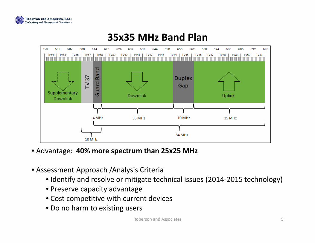
35x35 MHz Band Plan
Roberson and Associates 5
• Advantage: 40% more spectrum than 25x25 MHz
• Assessment Approach /Analysis Criteria
• Identify and resolve or mitigate technical issues (2014-2015 technology)
• Preserve capacity advantage
• Cost competitive with current devices
• Do no harm to existing users

Band Plan Comparison
Roberson and Associates 6

Band Plan-Specific Issues are Readily Manageable
• Antenna Length and RF Performance– Wider bandwidth, lower frequency � longer antenna
– Resolved by: • Re-tuning of 700 MHz antennas, slightly lower efficiency
• Minimal 0.4 cm3 size increase in a typical microstrip antenna versus 25x25 MHz band plan antenna falls within smartphone form factor
• Duplexer Filter Bandwidth– Larger pass band � greater filter design complexity
– Resolved by:• Using dual filters consistent with current technology and industry practices
• Migrating to single filter using 2015/2016 technology advances, if appropriate
• Harmonic Interference– Lower Uplink frequency� 3rd Order Harmonic in PCS Band
– Resolved by:
• Low power level of third harmonic
• Standard harmonic filter at the transmit side
• Augmented isolation between transmit and receiver paths
Roberson and Associates 7

Device Antennas for 35x35 MHz Band Plan Are Priced
and Sized for Rapid Commercial Deployment
Roberson and Associates 8
Technical Issue Performance
Issue(s) or
Concern(s)
Resolution
Approach(es)
Result
• Single device antenna
covering wider
bandwidth
• Antenna Length Increase
causes slight -0.32 dB
detuning (vs 25x25
plan)
• Antenna efficiency
causing degraded
detuning of -0.6 dB
(vs 700 MHz antenna)
• Larger antenna size
compatible with handset
• Optimize antenna for
600 MHz uplink
• Increase base power
• Advanced antenna
design*
• Capacity still exceeds
other plans significantly
• Negligible throughput
decrease
• Minor antenna structure
size increase-compatible
with (4-5 inch
smartphones)
• Advanced antenna
designs resolves issues
•Use of typical 3-5 cm3 active antennas, innovative printed circuit board antennas, and
other technological advances already in place in existing smartphones, or under
development at half the size of a traditional passive antenna

LTE Antennas Can Support a 35x35 MHz Band Plan in
Commercially Acceptable Form Factors
Roberson and Associates9
Pulse Electronics ( 3.2 cc)Etheretronics (33x15x11 mm3)
Antenna
Antenna
Connectors
HTC Evo LTE smartphone
Antenna
Antenna
top

Duplex Filter Solutions Exist for
35x35 MHz Band Plan
Roberson and Associates 10
Technical
Question
Performance
Issue(s) or
Concern(s)
Resolution
Approach(es)
Result
• Filter Design for
Wide Pass band
• Appropriate filter
response characteristics
for 35 MHz pass band
• Dual, overlapping
duplex filter
structure*
• Advanced duplexer
materials
• Required
performance achieved
• Slight cost increase,
mitigated by unit
volumes
• Advanced duplexer
approaches resolve
issues*
Well known, current industry practice uses dual-filter configuration for wide pass band
*Migration to a single filter solution feasible in the 2015 timeframe as technology advances

Dual Duplex Filters Can
Cover an Expanded Pass Band
Roberson and Associates 11
• Current (single) duplex filters support 28-30 MHz pass band
• 25 MHz overlapped filters achieve 35 MHz pass band
2.5 x 2.0 x 0.7 mm
Duplexer 2
Duplexer 1 Duplexer 1
Duplexer 2
10 MHz
Duplex
Gap
25 MHz
25 MHz
698 MHz618 MHz

Harmonic Effects Raise Few Concerns
Roberson and Associates 12
User device transmitter
creates harmonic effects at multiples of the
uplink frequency, but each multiple has
progressively lower power
Low power level of third harmonic
in PCS receive band will not
degrade PCS performance

Mobile –TV Co-existence Introduction• First, set the Duplex Gap location for mobile broadband
• Second, allow the broadcast stations “eat” into the uplink in certain markets when necessary
• Both assumptions incorporated in the FCC and T-Mobile proposed band plans– Reduces the number, scope, and scale of interference scenarios
– Prevents a few markets from reducing the broadband spectrum available elsewhere
Roberson and Associates 13
↑Duplex
Gap↓TV
37
Gu
ard
Ba
nd
Duplex
Gap↓TV
37
Gu
ard
Ba
nd
Gu
ard
Ba
nd
TV ↑
Market A
At least 84 MHz
available
Market B
Less than 84 MHz
available
Roberson and Associates 13G
ua
rd B
an
d

Mobile –TV Co-existence Cases
Roberson and Associates 14
↑Duplex
Gap↓TV
37
Gu
ard
Ba
nd
↓TV
37
Gu
ard
Ba
nd
TV ↑
Market A
At least 84 MHz
available
Market B
Less than 84 MHz
available
Case 1 – Adjoining Geographic Region, Co-Channel
- Scenario 1: Address TV interference with cellular uplink (at base receiver)
- Scenario 2: Address Cellular UE device interference with TV receiver
Case 2 – Overlapped and Adjoining Geographic Regions, Non Co-Channel
- Address TV interference with cellular uplink (at base receiver)
Roberson and Associates 14
Duplex
Gap
Gu
ard
Ba
nd
Analysis will focus on broadcast TV in the Uplink
Gu
ard
Ba
nd
Ca
se 1
Case 2

Case 1 – Adjoining Geographic Region, Co-Channel
Roberson and Associates 15
Market A
: Desired Signal
: Interfering Signal
Market B
Scenario 1
Scenario 2
Scenario 1 – High power TV broadcast to base station receivers. Kilowatt TV transmitters
transmitting into cellular base station receivers designed to receive microwatt power levels.
Scenario 2 – Low power mobile handsets to TV receivers. milliwatt device transmitters
transmitting into TV receivers designed to receive microwatt power levels.
Cellular
Base
TV
Broadcast
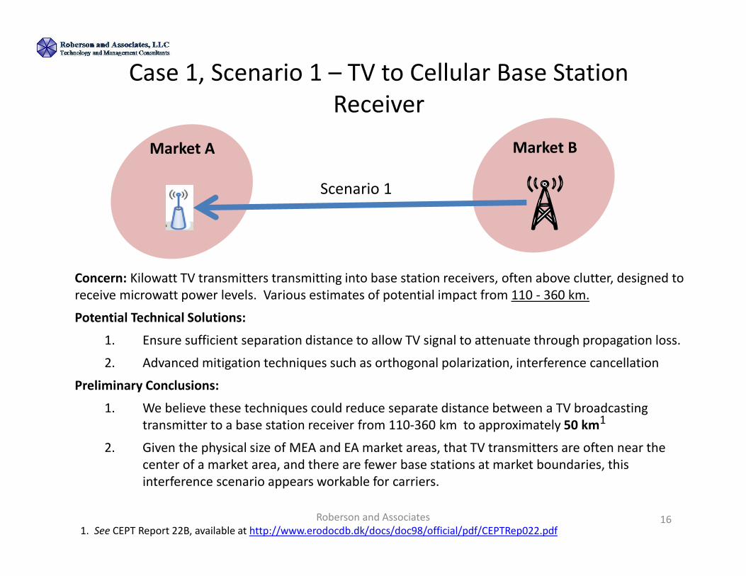
Case 1, Scenario 1 – TV to Cellular Base Station
Receiver
Roberson and Associates 16
Market A Market B
Scenario 1
Concern: Kilowatt TV transmitters transmitting into base station receivers, often above clutter, designed to
receive microwatt power levels. Various estimates of potential impact from 110 - 360 km.
Potential Technical Solutions:
1. Ensure sufficient separation distance to allow TV signal to attenuate through propagation loss.
2. Advanced mitigation techniques such as orthogonal polarization, interference cancellation
Preliminary Conclusions:
1. We believe these techniques could reduce separate distance between a TV broadcasting
transmitter to a base station receiver from 110-360 km to approximately 50 km1
2. Given the physical size of MEA and EA market areas, that TV transmitters are often near the
center of a market area, and there are fewer base stations at market boundaries, this
interference scenario appears workable for carriers.
1. See CEPT Report 22B, available at http://www.erodocdb.dk/docs/doc98/official/pdf/CEPTRep022.pdf

Roberson and Associates 17
Case 1, Scenario 2 –Mobile Handset to TV Receiver
Market A Market B
Scenario 2
Concern: Low power mobile handsets to TV receivers. milliwatt device transmitters transmitting into TV receivers designed to receive microwatt power levels.
Potential Technical Solutions:
1. Low power transmission nature of handsets means handset must be within meters of TV receiver to cause interference, not kilometers.
2. Since there is separation distance between the TV station and the cellular base station from Case 1, Scenario 1 and the coverage of the cellular system is small, the likelihood of the UE device interfering with a typical TV receiver is also small
Preliminary Conclusions:
1. Given the physical size of MEA and EA market areas, TV transmitters are often near the center of a market area. Since there are fewer base stations at market boundaries, this interference scenario has low likelihood.

Case 2 – Overlapped and Adjoining Geographic Regions,
Non Co-Channel
Roberson and Associates 18
Concern: Kilowatt TV transmitters transmitting into base station receivers and mobile handsets transmitting into TV receivers. Primary interference concern is for base station receivers.
Potential Technical Solutions:
1. 9 MHz Nominal Guard band between TV 47 (and TV 48 if necessary) and cellular uplink block
2. Place a moderate power TV transmitter (50 KW) into TV 47 instead of 1 MW
Preliminary Conclusions:
1. Large separation distance between TV and Base station not required (guard band can be used)
2. Prevents a few markets from reducing overall spectrum elsewhere
3. Occurs only when 13 TV stations (78 MHz) or less are recovered, not the usual situation.
4. This “eating” into the uplink provides some paired spectrum even if only 12 TV stations are recovered
608 614 620 626 632 638 644 650 656 662 668 674 680 686 692 698
Duplex
Gap↓TV
37
Gu
ard
Ba
nd
TV
47
Gu
ard
Ba
nd
↑
TV50TV49TV48TV47TV46TV45TV44TV43TV42TV41TV40TV39TV38TV37 TV51
Gu
ard
Ba
nd
Concern

Summary
• The 35x35 MHz band plan provides
– Efficient usage of the spectrum
– Maximum Feasible Operating Spectrum Above Channel 37
• The 35x35 MHz Plan is feasible
– All technical issues are addressable
– Leverages current industry practices and expected technology advances
– Practical mitigation measures for potential interference both with other LTE systems and TV operations
Roberson and Associates 19

Appendix
Roberson and Associates 20

Filtering and Frequency Selection Solve
Modest Harmonic Effects
Roberson and Associates 21
Technical
Question
Performance Issue(s)
or Concern(s)
Resolution
Approach(es)
Result
• Harmonic
power of user
device
transmitter
• 4.5% Interference
with PCS band
receiver (3rd
harmonic)
• Minimal
Interference with
BRS band (4th
harmonic)
• Improved RF
harmonic filter
• Coordination
of 600 MHz and
PCS operation
through
frequency
selection
• No degradation
to PCS or BRS
band device or
user
The low power and relatively low likelihood of occurrence of harmonic power into
the PCS band can readily be addressed by better isolation and harmonic filter technology.

Characteristics in Common with
Other Commenter Proposed Band Plans
• Addresses intermodulation and large uplink/downlink separation issues of FCC Band Plan
• Channel 37 (608-614 MHz) to continue to be used for medical and other low power applications
• 5 MHz paired interchangeable FDD blocks
• Potential use of Supplementary Downlink (SDL) operations below the paired downlink boundary
• Leverages design approaches already being used in the 700 MHz band
Roberson and Associates 22

Characteristics in Common with Other Band Plans
• Size of Duplex Gap
• Mitigation of TV Interference
• Relocation of the TV operations from the uplink
spectrum because of substantial impact on cellular
operations
• Coordination with the TV operations in Canada and
Mexico to avoid co-channel and non co-channel
interference
Roberson and Associates 23

Duplex Gap and Allowable Applications
• A Ten Megahertz Duplex Gap Is Technically Feasible
• The Duplex Gap Can Support Useful Services
– Recommend low power operations, such as wireless microphones or indoor unlicensed operations
– Do not recommend high-power operations, such as television
• Creates strong potential for intermodulation interference with 600 MHz downlink
• Requires wasteful guard bands to provide sufficient attenuation to protect 600 MHz broadband services
Roberson and Associates 24