team 146: project engineering notebook rocky … 146: project engineering notebook rocky mountain...
TRANSCRIPT

Team 146: Project Engineering Notebook
Rocky Mountain BEST Robotics 2012
Coach: Joel A. Kirkland
720-341-0376 (cell)

1 | P a g e
1 Executive Summary ................................................................................................................. 2 2 Design Process ......................................................................................................................... 2
2.1 Problem Statement ........................................................................................................ 2
2.2 Overview of Engineering Design Process ................................................................... 3
2.3 Brainstorming ............................................................................................................... 4
2.4 Strategy Evaluation....................................................................................................... 4
2.4.1 Strategy Overview .................................................................................................... 4 2.4.2 Final Strategy ............................................................................................................ 5
2.4.2.1 Basics ................................................................................................................ 5
2.4.2.2 Offensive Strategy ............................................................................................ 5
2.4.2.3 Defensive Strategy ........................................................................................... 8
2.4.2.4 Strategies’ Effect on Design Elements ............................................................. 9
2.4.3 Design Elements ....................................................................................................... 9 2.4.3.1 Offensive design elements ................................................................................ 9
2.4.3.2 Defensive Design Elements ............................................................................ 10
2.5 Robot Design .............................................................................................................. 10
2.5.1 Preliminary Design Overview ................................................................................. 10 2.5.2 Base and Winch ...................................................................................................... 11
2.5.2.1 Base and Winch Alternatives ......................................................................... 11
2.5.2.2 Final Base and Winch ..................................................................................... 12
2.5.3 Arm ......................................................................................................................... 12 2.5.3.1 Arm Alternatives ............................................................................................ 12
2.5.3.2 Final Arm ....................................................................................................... 13
2.5.3.3 Regional Arm ................................................................................................ 13
2.5.4 Claw ....................................................................................................................... 14 2.5.4.1 Claw Alternatives ........................................................................................... 14
2.5.4.2 Final Claw ...................................................................................................... 15
2.5.4.3 Regional Claw ............................................................................................... 15
2.6 Mathematical Analysis ............................................................................................... 16
2.6.1 Optimization of Robot winch.................................................................................. 16 2.7 Programming .............................................................................................................. 21
2.8 Robot Integration and Testing ...................................................................................... 22
3 Team Organization and Meeting Minutes ............................................................................ 23 4 Safety .................................................................................................................................... 24 5 Research Paper ...................................................................................................................... 26 6 Appendix ............................................................................................................................... 31

2 | P a g e
1 Executive Summary
Warp XX provides a multitude of challenges. In order to surmount all of these challenges
and succeed in the competition, we split into separate teams and divided up the work. To further
our effectiveness as a team, we also followed the engineering design process. We stated the
problem, generated and analyzed concepts,
prototyped and designed robot elements,
produced the robot parts, integrated components
and then tested our machine (see Figure 1). Our
strategy team began the six week build period by
defining the rules, regulations and requirements.
They then developed a basic strategy. Our design
team took this strategy and used it to generate prototypes and computer models of our robot. Our
mechanical team then took these designs and used them built our final robot. This robot was then
rigorously tested and improved via our driver team. Programming of the robot was done
throughout this entire process. While our robot was being constructed, our notebook team was
simultaneously working to gather documentation of our robot build. This documentation was
then used to put together this engineering notebook.
2 Design Process
2.1 Problem Statement
DARPA has given us the challenge of producing a prototype robotic system that
functions as an effective cargo transport between Midway Station and the island on Earth. The
robot’s constraints are as follows: it must fit in a 24 inch cube, weigh no more than 24 pounds,
Figure 1: Completed Robot
3 | P a g e
have a safety cable and be built entirely out of BEST provided parts. Its requirements include
climbing a ten foot tall “space elevator” and manipulating game pieces such as cargo balls, waste
balls, fuel bottles, T-structures, solar panels and habitation modules; however, not all of these
components have to be handled. The goal of the robot is to manipulate as many of these game
field pieces as possible to score well during the competition. All of these requirements,
constraints, and goals require not only a great design, but also a well-defined strategy. This
strategy must then be converted into an optimal design. This design must then be carefully built
using the provided materials. Finally, this large multitude of tasks can only be accomplished if
our team develops and utilizes an efficient organizational structure, as well as a strong schedule
and sense of time management.
2.2 Overview of Engineering Design Process
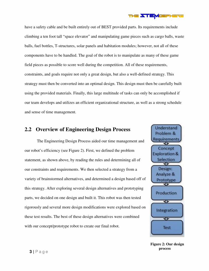
The Engineering Design Process aided our time management and
our robot’s efficiency (see Figure 2). First, we defined the problem
statement, as shown above, by reading the rules and determining all of
our constraints and requirements. We then selected a strategy from a
variety of brainstormed alternatives, and determined a design based off of
this strategy. After exploring several design alternatives and prototyping
parts, we decided on one design and built it. This robot was then tested
rigorously and several more design modifications were explored based on
these test results. The best of these design alternatives were combined
with our concept/prototype robot to create our final robot.
Figure 2: Our design
process

4 | P a g e
2.3 Brainstorming
For our brainstorming method, we used multiple large white boards to write down any
and all potential design ideas suggested by team members (see Figure 3). Then the robot team
compared these ideas against each
other, tested them for their viability
and eliminated any ideas that
couldn’t be fabricated or weren’t
effective. In short, the robot team
conducted an in depth analysis on
each design. For the few ideas that
were left after this process, we then
commenced the process of debating
about which designs were more operative, which often led to compromises between ideas and a
better end product. This also allowed a point-by-point comparison of the merits of ideas. For
example, there was a contentious debate about the material we would use to make the arm move.
Such debates also led to possibilities that had not yet been explored. In many cases, there was
also math involved in finding the best design, (see Math Analysis section 2.6). For more specific
brainstorming pertaining to different parts of the robot, see section 2.5.
2.4 Strategy Evaluation
2.4.1 Strategy Overview
Our strategy was straightforward; we would switch the bottles and then try for the
habitation module and solar panels. This would put us at the top of the unitstrut, allowing us to
Figure 3: Brainstorming on a white board

5 | P a g e
get the summit bonus. Our secondary objective was to knock off the waste balls, and move the
cargo balls if time allowed. The robot design behind this strategy would be a rotating arm with a
versatile claw on one end. (See appendix Figures 15 and 28)
2.4.2 Final Strategy
2.4.2.1 Basics
One of the most influential factors on the design of the robot is the strategy. It outlines
exactly what the goals of the robot are. Knowing that this strategy will dictate how the robot will
perform on game day, we spent a good deal of time outlining, detailing, refining and optimizing
our strategies. As this year’s game has very little robot interaction, we decided that our offensive
strategy was far more important and therefore began working on it first. After developing our
offensive strategy, we then proceeded to evaluate how we would react if certain parts of our
robot were to stop working. This evaluation was eventually compiled into a detailed defensive
strategy. Our offensive and defensive strategies are described below.
2.4.2.2 Offensive Strategy
The offensive strategy was one of the deciding factors in the design of the robot. Only
after the strategy is determined can the robot-build team learn the functions the robot needs to
perform. The strategy team generated this complexity chart (see Figure 4) to support a
quantitative decision. (see appendix for strategy brainstorming in Figure 10,11, 12, and 22)

6 | P a g e
Objectives
Quantity
(# of pieces
on game field)
Score
value
Relative difficulty
Scale of 1(easiest) –
7(hardest)
Absolute difficulty
Scale of 1(easiest) –
10(hardest)
Habitation
Module 1 11 6 9
T-Structure 1 3 7 10
Fuel Bottle
(empty) 1 7 4 6
Fuel Bottle
(full) 2 6 3 6
Solar Panel 1 5 5 5
Cargo Ball 4 3 2 4
Waste Ball 2 1 1 2
Figure 4: Complexity Chart
The chart was very helpful because it clearly showed us not only what we could and couldn’t
do, but also the relative difficulty of doing each of these objectives. The difficulty numbers were
deduced by comparing how difficult it would be to design a robot that could accomplish the task
Color Code
Do-able
Not do-able
Primary objectives

7 | P a g e
being debated. These comparisons allowed our strategy team to assign a relative difficulty to
each task, which ranked the seven possible tasks from easiest to hardest. (See figure 5)
Figure 5: Strategy Decision Matrix
This difficulty factor, and other factors such as the time taken to complete the task, were all
compiled into the absolute difficulty. From these numbers, we were able to separate our primary
and secondary objectives (the do-ables), from the tasks we decided were too difficult to attempt
(the not do-ables).
Based upon these findings, the T-Structure was ruled out as a viable part of our strategy.
Moreover, it was determined that the full fuel bottle, the empty fuel bottle, the solar panels and
the waste balls were primary objectives. Lastly, the habitation module and the cargo balls were
seen as secondary objectives and were only to be attempted if time permits. We then determined
the order that we wanted to complete our primary objectives in. This order was established by
placing our easiest tasks (in terms of absolute difficulty) first, and then following up with our

8 | P a g e
harder objectives. This is our final offensive strategy in the sequential order that it will be
performed on the field, so long as the need for one of our defensive strategies does not arise:
Primary:
1. Go for the fuel bottles
2. Go for the solar panels
3. Go for the waste balls
Secondary:
4. Get the cargo balls
5. If time permits, mount the habitation module
2.4.2.3 Defensive Strategy
The defensive strategy was heavily based upon Murphy's Law. Multiple failure scenarios
were envisioned, and ways to circumvent these setbacks were thought of on an issue-by-issue
basis. Every element in these lists is what was evaluated as a viable part of the defensive
strategy.
Defensive Strategy, based on failing component(s):
Claw Servos fail
1) Get the waste balls
2) Get the summit indicator
3) Get the solar panels,
4) Mount the habitation module if time allows us to do so
Ascension systems fail
1) Get waste balls
2) Rapid Turnaround bonus
Broken Shoulder
1) Get summit bonus
2) Rapid turnaround bonus
3) Solar Panels
Broken elbow
1) Waste cargo ball
2) Fuel Bottles
3) Summit

9 | P a g e
4) Rapid turnaround bonus
Remote Failures 1) We’re in trouble
2) Get rapid turnaround bonus
2.4.2.4 Strategies’ Effect on Design Elements
Our design needed to meet the requirements of our strategy. It had to be capable of
manipulating both solar panels and fuel bottles, ascending and descending the unistrut and
toggling the summit indicator. Because our strategy called for switching out the fuel bottles
quickly, the optimum design for our robot is a double-clasper claw. This claw also had to carry
solar panels, a goal which necessitated a fixed, wooden center piece. Our strategy also needed a
rapid ascent and descent, so our robot had to be very light.
2.4.3 Design Elements
2.4.3.1 Offensive design elements
Our robot this year was designed primarily to be an offensive robot, because the lack of
robot-to-robot interaction in this year’s game diminishes the need for a defensive design. The
major offensive points of our robot include our telescopic arm, our dual-grabbing claw, and our
two-motor winch, which allowed us to gain a substantial amount of points. The telescopic arm
was designed to extend and provide the range of motion needed to manipulate bottles, solar
panels, and cargo balls. It provided us with 30 inches of reach, and could swing around 180
degrees, allowing for object handling on both the right and left facing platforms. The claw was
also a crucial offensive part of our robot. It was specifically designed to pick up bottles and
transport solar panels, coinciding with our offensive strategy. Our two-motor winch allows our
robot to gain the summit bonus and move pieces between the base and Midway Station quickly.

10 | P a g e
2.4.3.2 Defensive Design Elements
Due to this year’s game field, our robot didn’t have to interact with other robots, which
greatly reduced the need for defensive design elements. However, the vertical ascension of our
robot required that we protect it from the many forces exerted on it during the climb. Our winch
was securely mounted to our base using wood in order to avoid putting stress on the motor
shafts. A wooden guard that surrounded the unistrut was placed on the front of the robot in order
to prevent the machine from rotating around the strut and thus causing much more stress. This
guard also prevented the robot from getting damaged via collisions with the unistrut, as a free
swinging robot could hit the strut and get damaged. Another defensive element was our base
which was made as light as possible, in order to make our robot faster and more efficient when
climbing the “space elevator.”
2.5 Robot Design
2.5.1 Preliminary Design Overview
The prerequisites of our design were derived from our already established robot
constraints, goals, and requirements. The constraints on our robot mostly came from the official
rules, such as the weight requirement and the 24” cube, also with a 24 pound weight limit. Our
requirements were things that our robot needed to do to be able to function effectively and
conform with the rules. Our goals were derived from the objectives in our strategy.
In the end, the many ideas that we generated while brainstorming were consolidated into
one design. This design was then built and rigorously tested. This testing often led to design
tweaks and changes, all of which are discussed in our testing section. (See Appendix Figure 14
for basic material.)

11 | P a g e
2.5.2 Base and Winch
2.5.2.1 Base and Winch Alternatives
With the strategy we chose, our robot was required to go up and down the “space elevator”
twice. This put a lot of stress on the ability of the robot to ascend and descend. We had a few
different ideas as to how we would accomplish this task. One was a cog wheel system that dug
into the slots in the unistrut. This idea was rejected very quickly because of the precision
required. The teeth would have to be extremely uniform, and if there was any variation between
the unistrut we used to test, and those of the competitions, our ascension mechanism would fail.
Another proposed idea was to have two rubber wheels on either side of the unistrut, which used
friction to make the robot ascend as they turned. These were also evaluated to be risky, as they
may slip, which would be exaggerated the heavier our robot became. Finally, we had the idea of
using a winch. The winch would resolve many of the issues of the other mechanisms. It would
also be fast and light.
With the ascension method decided, we started discussing platforms to mount the winch,
as well as other components to. One of the first designs we went through for the base was having
a frame completely made out of PVC. The PVC would provide a full size frame while being
significantly lighter than a solid frame. It was decided that a PVC frame would be very difficult
to work with, as mounting the components necessary to ascend and manipulate objects would be
very impractical. We decided to use wood for the frame instead, because it was light and easy to
work with. With the material decided, we needed to find a shape that would meet our
requirements of being as light as possible so that we could ascend quickly, while still being able
to mount all of the necessary components. Originally we thought of building a box, but this was
rejected, due to the weight a wooden box would have. So, it was decided that just the side

12 | P a g e
adjacent to the pole and the one on top were necessary. This gave us enough space to mount the
electronics and other required components, while still being as light as possible. In order to test
the validity of our design, we made a prototype robot that was a working representation of the
base design.
2.5.2.2 Final Base and Winch
Our base was the most essential part of our robot because it served as the mounting
platform for all our other parts. For our final design, we did not alter our prototype much. For our
design, we had two pieces of plywood at ninety degree angles to one another. We cut down the
size of these platforms to optimize our ascent speed. We also attached blocks of wood lined with
PVC, to keep our robot securely attached to the pole. Finally, we found an optimal position to
attach the cortex and the battery: near these PVC mounts. Our winch stayed the same from our
first design, because it worked effectively in testing.
2.5.3 Arm
2.5.3.1 Arm Alternatives
After we had a solid base, we worked on constructing the arm, so that we could reach all
of the game pieces. This was difficult because the strategy required it to extend 30” from the
unistrut, while still fitting inside of the 24” cube. It also had to have a 180 degree range of
motion, in order to be successful on both platforms. The 30 inch range of motion inside a 24 inch
constraint prompted the idea of a telescopic arm. Our first design was built out of PVC. Two
PVC tubes were nested inside of each other, and were tensioned with a rubber band. A string
would then be attached in such a way that, when pulled, the PVC would extend. When released,
the rubber band would snap the pieces back to their resting state. Numerous flaws were

13 | P a g e
encountered with this design. We realized that the string was not a reliable source of motion, as it
would often get frayed, or caught on something, which would immobilize our arm. The arm also
didn’t provide us with the reach we needed, so we went back to the drawing board. The PVC was
replaced with the sliding rail in our second design, and the string was replaced with the wiring
conduit, which was used as a chain to pull and push the slider. The conduit was robust, and the
slider provided us with a sufficient range of motion.
2.5.3.2 Final Arm
The arm and elbow joint on our robot progressed to more effective designs as we
discovered fatal flaws in the previous prototypes. In order to achieve the required reach, we used
the slider and conduit design detailed above. The sliders were screwed to the turntable, which
was more weight-bearing than the wood pivots we had used previously. A motor mounted to the
turntable wrapped and unwrapped the wiring conduit, which was attached to the end of the upper
slide (which replaced the inner arm). The decision to use the conduit was made because it was
stiff enough to both push and pull the arm. This allows both the upper and lower arm rails to
move in and out, greatly extending our range of motion and allowing us to fit in the 2 foot
requirements.
2.5.3.3 Regional Arm
During game day and in testing we noticed problems with the extension of the arm. One
of the major ones was that the conduit sometimes expanded outward instead of pushing and
pulling the arm in a linear fashion. This reduced or eliminated our ability to extend our arm.
There were a wide variety of proposed suggestions to fix the arm. There was a suggestion to
remove the chain all together and create a notched belt for the gear to mesh with. There was also
an idea to turn the sliders for the arm sideways so as to mount them the way they were supposed
14 | P a g e
to go, and along with that idea come several variations of a string-based pulley to extend and
retract the arm. Many of those ideas solved the problem of the conduit unraveling outward, but
there were also ideas to
restrain that using such
things as a zip tie, an
extended hook or even a
plastic ring wrapping all the
way around both rails.
However, the best idea was
suggested last, which was
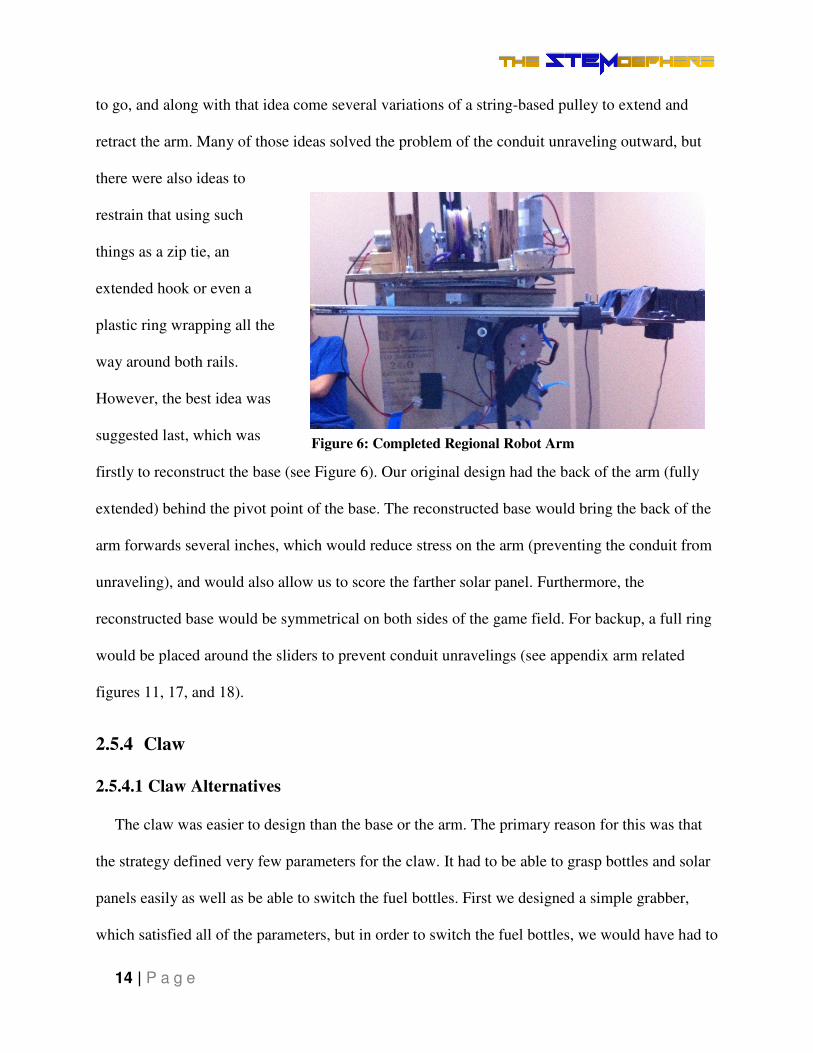
firstly to reconstruct the base (see Figure 6). Our original design had the back of the arm (fully
extended) behind the pivot point of the base. The reconstructed base would bring the back of the
arm forwards several inches, which would reduce stress on the arm (preventing the conduit from
unraveling), and would also allow us to score the farther solar panel. Furthermore, the
reconstructed base would be symmetrical on both sides of the game field. For backup, a full ring
would be placed around the sliders to prevent conduit unravelings (see appendix arm related
figures 11, 17, and 18).
2.5.4 Claw
2.5.4.1 Claw Alternatives
The claw was easier to design than the base or the arm. The primary reason for this was that
the strategy defined very few parameters for the claw. It had to be able to grasp bottles and solar
panels easily as well as be able to switch the fuel bottles. First we designed a simple grabber,
which satisfied all of the parameters, but in order to switch the fuel bottles, we would have had to
Figure 6: Completed Regional Robot Arm

15 | P a g e
make two trips up the unistrut. This lead to the creation of a double grabber system, in which two
independently operated claspers were placed at the end of the arm. One grabber would pick up
the full fuel bottle at the bottom, and after the robot had scaled the unistrut, the second grabber
would grab the empty fuel bottle, and with a slight sideways movement of our arm, the full fuel
bottle would be attached at the top. The empty fuel bottle would then be brought down and
placed in its holder. This allowed us to exchange the bottles in just one trip. The claw was also
outfitted with a solid, fixed piece of wood in the center that both pincers used as their counterpart
(refer to appendix for pictures of the claw in Figures 15, 19, and 28). This center piece was great
for handling solar panels because the wood piece conjoined with the center hole of the solar
panels.
2.5.4.2 Final Claw
Our final claw design was very similar to the preliminary design. It started with a four
way joint connected to the arm on one end, a wooden center piece parallel to the arm and a
grabbing clasper on either side of the center wood piece. The servo mounts were made of sheet
metal running perpendicular to the arm, with the servos mounted in the middle. These servos
connected to the claspers using piano wire. This design worked fairly well, but in the final
assembly several improvements were made. To increase the stability of the claw, all of the
separate wood pieces were instead cut out of a single block of wood. The servos were mounted
closer to the joint so as to add leverage and make it level with the claw surface, and the distance
between the pivot point and the joint was decreased to make it easier to grip the fuel containers.
2.5.4.3 Regional Claw
To understand what improvements we’d need to make on our claw, we tested our existing
design on our game field. Specifically, our claw was tested to see if we could actually score a

16 | P a g e
habitation module. Unfortunately, the angle of our arm's rotation made it impossible to hang onto
the appropriate hook on the module, so the new claw was designed only to pick up the items that
the old claw could- fuel bottles and
solar panels. To decrease claw weight,
the new design was constructed out of
two layers of 1/8” plywood separated by
several pieces of the 1/2” thick board.
The servos were mounted at the very
ends, and the two claw claspers were
attached directly to those servos,
making them both have the exact same range. The new claw design was shaped so as to
optimally grip the bottles at the base, and grip solar panels well at the tip. This allowed both
items to be scored more easily, and added reliability for the drivers. That claw design made
scoring items more efficient, more reliable, and light enough to minimize the arm's sag (see
Figure 7).
2.6 Mathematical Analysis
2.6.1 Optimization of Robot winch
The winch, being a very complex system, involved a wide variety of math. We wanted to
be able to find the optimal winch radius for any weight that our robot could have. We decided to
go with a radius of 1 inch initially for testing, so calculating for the acceleration using a sum of
forces equation gives:
�� = ����� − ���� � = ����� ∗ �
Figure 7: Finished Regional Claw

17 | P a g e
����� − ���� ������
= �
��� ��∗������� −����� ∗ ������
= �
2.6585 � ∗ 20.0254� − 5.443$� ∗ 9.806 �&�
5.443$� = �
28.6527 �&� = �
Using this value for acceleration, and since we know that the height of the pole is 10 ft., it’s
possible to derive the time it takes to climb the pole.
()*+ = 12 )�+*� + ./* + (/
Assuming that the initial velocity and position ./ = (/ = 0:
3.048� = 12 028.6527�&�1 *
�
* = 0.4612535& Obviously this number is unrealistic; the robot can’t climb the pole in less than half a second
based on actual testing. So what is missing from the equation? Drag! This includes motor and
drive train drag and friction along the pole. The linear drag is fairly easy to figure out, as it is just
a drag coefficient multiplied by velocity:
�� = ����� − �2� − ���� � = ����� ∗ �
����� − 34 −����� ∗ � = ����� ∗ �
The motors’ drag, being related to angular velocity was slightly more complicated to
calculate. We started by finding a sum of torques equation:
Where I is rotational inertia, and 5′′ is rotational acceleration.

18 | P a g e
�� = ��� �� − �2� − ����� = 7��89� ∗ 5′′
��� �� − :5; − ����� ∗ ���89� = 7��89� ∗ 5′′
We solved both equations for ����� and used that to set them equal to each other.
34 + ����� ∗ � + ����� ∗ � = ��� �� − :5; − 7��89� ∗ 5;;
���89�
In this equation we had terms of both angular and linear velocity and acceleration. We used
the formula for arc length to find a relationship:
<���� = ���89� ∗ 5
<�������89� = 5
Where <���� is the length of rope on the spool and 5 is the amount of radians the spool has
turned. Using this, we found 5;and 5′′.
5; = 4���89�
5;; = ����89�
We then used these to put our equation entirely in terms of linear velocity and acceleration.
34 + ����� ∗ � + ����� ∗ � =��� �� − :4
���89� −7��89� ∗ ����89�
���89�
We then put this into the ordinary differential equation form
=����� ∗ ���89� + 7��89����89�>� + =3 ∗ ���89� +:
���89�> 4 = ��� �� − ���89� ∗ ����� ∗ �
Following this, we made some assumptions to make the equation easier to solve.

19 | P a g e
We assume the term ?@ABCD�@ABCD was much smaller than ����� ∗ ���89�, so much so that it was
irrelevant.
����� ∗ ���89� >> 7��89����89�
In a similar manner we assumed that the drag was primarily in the motor, meaning that the
linear drag was mostly irrelevant.
γ ∗ rGHIJK << β
rGHIJK
This left us with:
����� ∗ ���89� ∗ � + :4���89� = ��� �� − ���89� ∗ ����� ∗ �
During testing of a prototype robot, we noticed that the robot reached a steady velocity very
quickly. We calculated the average speed of the robot during the entire time it took for it to climb
the pole.
&���� = M �����2* N�8
&���� = MOP − M/18&
&���� = 3.048� − .305�18&
&���� ≈ . 152ms
Using this we assumed that acceleration was ≈ /�TU and velocity was ≈
.OW��T . Using these we
solved for :
: = )��� �� − ���89� ∗ ����� ∗ � − ����� ∗ ���89� ∗ �+ ∗ ���89�4

20 | P a g e
: =0)5.3 �+ − ).025�+ ∗ )5.44$�+ ∗ )9.8�&� + − )5.44$�+ ∗ ).025�+ ∗ )0+1 ∗ ).025�+
). 152�& +
: = . 6525$� ∗ �&
Now we solved the differential equation for v(t) using Wolfram alpha1.
����� ∗ � ∗ ���89� + :4���89� = ��� �� − ���89� ∗ ����� ∗ �
4)*+ = −���89� ∗ )� ∗ ����� ∗ ���89� − ��� ��+: ∗ )1 − X
YZ �[\]\^∗�@ABCDU +
Inserting our known values and assuming a constant time, we are left with v(m, r).
4)����� , ���89�+ = −���89� ∗)9.8 ∗ ����� ∗ ���89� − 5.3+
. 6525 ∗ )1 − XY.`W�W∗a
�[\]\^∗�@ABCDU +
Graphing this equation we got:
1 Wolfram|alpha: Computational knowledge engine. (2012). Retrieved from
http://www.wolframalpha.com/

21 | P a g e
Evaluating this function for our current robot weight of 5.44 kg:
According to the graph the optimum winch radius would be 2”. So we remade our winch to have
a radius of 2”.
2.7 Programming
Programming is an essential part of any robot. It’s what turns a mechanical assembly into
a fully functional and controllable robot. We started by making a list of software requirements
(see Figure 8).
-0.5
-0.4
-0.3
-0.2
-0.1
0
0.1
0.2
0.3
0.4
0.5
0 0.025 0.05 0.075 0.1 0.125 0.15
ve
loci
ty (
m/s
)
rwinch (m)
Velocity at mrobot = 5.44 kg
optimum rwinch = 0.05 m
Figure 8: Programming and Software Requirements

22 | P a g e
Next we designed the way the program would work, keeping the requirements in mind.
After that we started doing the actual coding in RobotC, which we chose due to the large amount
of freedom it offered. We started by making specific functions in charge of retrieving inputs and
controlling actuators. Next came the hard part, creating the code that would use the inputs to
determine the appropriate actuator settings. During this process we used a great deal of math, and
a large amount of testing. Finally, we had the drive team test the code and followed the feedback
they gave us to further improve the program (see appendix figures 16 and 25).
2.8 Robot Integration and Testing
After all of the robot’s components had been fabricated, they were tested individually
using our personal game field and game pieces. Following testing and refining, these parts were
integrated into one system according to our preplanned integration scheme. This outline was
drawn out by our robot team to avoid any mechanical interference between parts. After the
program was loaded on to our cortex and our robot was assembled and integrated, it was tested
on our game field.
After completing our initial robot, we had to test it to ensure proper functionality and work
out any bugs. It was beneficial that we did this because we were able to identify game breaking
flaws in our arm design, the elbow joint and the shoulder joint, as previously stated in the design
alternatives sections. The first thing we tested was the ascension method and the shield that
confined the robot to the unistrut. Our ascension method worked quite well, going up in eighteen
seconds and down in thirteen seconds. We also tested the elbow joint separately; that is how we
identified the problem of our rubber band and PVC arm not being able to meet the standards we
required for extension. After revision, we came back and tested it again, this time with it being
able to extend to the length that we needed it to. We then had to test the claw, and it managed to

23 | P a g e
fulfill our expectations by grabbing both fuel bottles and a solar panel (see Figure 9). As
previously mentioned, we also tested our completed robot, with all necessary revisions made, on
our game field during timed matches to simulate a Game Day experience.
Figure 9: Robot Testing
3 Team Organization and Meeting Minutes
The construction of an efficient, well-constructed robot necessitates good time
management as well as effective work distribution. Our team developed a thorough schedule and
daily agendas. With our mentors’ lessons in project management skills, team leads decided what
needed to be done at each meeting. These schedules and agendas were then dynamically updated
based on the agendas completed during each meeting. We also divided our team into smaller
sub-teams, each of which performed a specific set of tasks. For example, the claw team devised a
claw, the arm team built an arm, and the robot lead saw through the integration of all of these
pieces. Each team had a lead responsible for his/her team. Leaders were assigned based on skill
level, meaning that leads had to have experience in robotic competitions, an understanding of the
rules and requirements and good leadership qualities. The rest of the team chose what team they
would like to work in based on their interests and their abilities. Our team was organized as
24 | P a g e
shown in the Appendix. (For appendix figures based on team organization, meeting minutes, and
meeting schedules see figures 23, 24, and 27).
4 Safety
In the eyes of the STEMosphere, it’s not worth the price of winning the competition if the
cost is injured teammates. We strive to create a safe environment where the odds of having an
accident are significantly reduced; where all of our teammates watch out for each other and keep
each other safe.
We follow all common safety procedures: wearing safety glasses whenever a tool is in
use, covering our feet with closed-toed shoes in case anything is dropped, and maintaining a
stringent no-horseplay policy in our engineering lab. We also have a no food and drink policy
instituted in our lab to prevent spills and other potential safety hazards. In case of an emergency,
such as the rare event of a fire, we have practiced procedures that all members of the team are
familiar with. For example, should a fire start in our lab, all team members are to proceed in an
orderly, quiet fashion to the nearest door and exit the building.
Our team also realizes the importance of using the proper tools in the appropriate
situations. All team members are educated on the usage of tools such as drill presses, band saws,
etc.. Furthermore, any questions regarding tool usage can be answered by one of our four
engineering mentors. Each of these mentors is skilled in the usage of tools, and is prepared to
relay any of their knowledge to us students. All broken tools are also supposed to be reported
immediately to one of these mentors.
Other standard safety procedures that we follow include not wearing loose clothing in the
lab, and tying back long hair. We also have a fifteen minute session at the end of every workday
devoted to cleaning up, so that our lab remains clean and organized. We also always use a brush
25 | P a g e
to clean off machines after we’re done using them, because use of our hands could consequently
result in cuts and injury.
Much of this wisdom was imparted on us by our school engineering teacher. who has
years of personal and professional experience with engineering and proper safety procedures. We
spent a meeting taking notes on safety and all of us have a copy of those notes that we are
required to have signed by our parents, so as to ensure that we have learned and understood all of
the safety procedures.
We learned safety procedures for specific tools as well. For using the band saw, we had
to use a push block when the project allowed for it, keeping the block quarter of an inch away
from the object being cut and also to wait for the blade to stop completely before removing the
cut pieces. For the sander, we had to grip the object, and not use some other device to do so. If
there wasn’t a safe way to grip it, we would use a file. For the drill press, everything that had to
be drilled was clamped down. For the laser engraver, we had to have someone who was trained
to actually activate it. Those were our main rules, the rest were common rules such as always
having permission to use a machine, always having safety glasses, cleaning up after you were
done and other common sense rules such as keeping hands away from the blade. Only mentors
were allowed to use more hazardous tools, such as the table saw. (For safety content see
appendix Figures 13, 20, 21, and 26).
26 | P a g e
5 Research Paper
The idea of the space elevator has long been thought of as impossible, a concept to be
confined to the realm of science fiction. Having a giant elevator, many miles in length, reaching
up through the clouds and to the stars was just too much to hope for. However, that distant idea
is becoming a reality as scientists and engineers around the world are contemplating this
extraordinary concept.
The original concept of a space elevator came from a Russian scientist by the name of
Konstantin Tsiolkovosky around 19032. In an article he published, Tsiolkovosky proposed the
idea of an enormous tower that would reach all the way to GSO (Geo-Stationary Orbit), or the
point in space where an object would rotate at the same speed as the Earth, causing it to remain
over the same point on the Earth.
Ever since Tsiolkovosky first envisioned the idea, the concept of a space elevator has
developed and matured3,4. The first step in building a space elevator is sending up the first cable.
A small satellite would be sent into space aboard a rocket, containing the cable and a means to
position itself over the exact location where the elevator is to be built. Once in position, the
satellite would then deploy the cable, steadily running its length down. The cable would then be
secured at the base station, and a small robot, called a climber would be sent up the cable. As the
climber ascends the cable, it would add another cable onto the first, epoxying it into place. When
the climber reaches the top of the cable, it would add to the counter weight on the end of the
2 Price, Steve. "Audacious & Outrageous: Space Elevators." NASA Science Science News (7 Sept. 2000): n. pag. - NASA Science. Web. 19 Oct. 2012. <http://science.nasa.gov/science-news/science-at-nasa/2000/ast07sep_1/>
3 Edwards BC, Westling EA. The Space Elevator: A Revolutionary Earth-to-Space Transportation System. San Francisco, USA: Spageo Inc.; 2002. ISBN 0-9726045-0-2
4 Bonsor, Kevin. "How Space Elevators Will Work." Web log post. HowStuffWorks. N.p., n.d. Web. 19 Oct. 2012. <http://science.howstuffworks.com/space-elevator.htm>

27 | P a g e
elevator, further strengthening the structure. Subsequent climbers would be sent up the
increasingly large cable, each adding its own cable. Climbers would increase in size, with the
size of cable added increasing as well. Eventually, the cable would be strong enough to hold the
weight of the elevator itself.
Unfortunately, the largest obstacle is creating a cable strong enough to meet the needs of
the elevator, since all conventional materials have proven to be insufficiently strong. Not only
does it need to support the weight of the climbers, the cable needs to be able to support itself.
With the cable needing to reach beyond 62,000 mi5, which is above GSO, the cable would have
to taper outward, increasing in size at certain intervals in order for it to hold its own weight,
increasing to an immense, impractical width by GSO.
But with the recent discovery of carbon nanotubes, a viable new material for the cable
may be within reach4. Carbon nanotubes follow a similar molecular structure to diamonds, only
in the form of a tube. Initial measurements of the strength of these tubes have cautiously been
placed at 200 Giga-Pascals, an immense sum. This is comparable to a length of nanotubes equal
in size to a sewing thread lifting a large car. With estimates of the strength required for the space
elevator cable set at around 62 Giga-Pascals, carbon nanotubes are a candidate material.
Currently, the longest nanotube created is only about a foot in length, nowhere near the 62,000
miles needed. It may be impossible to grow a nanotube cable that long, but it is possible to use
nanotubes in a composite material, connecting individual tubes together with another substance.
Other nanotube material technologies such as boron nitride also have potential since they may be
easier to grow in long strands.
5 Hollingham, Richard. "Space Elevators: Going Up?" BBC Future (20 Aug. 2012): n. pag. Web. <http://www.bbc.com/future/story/20120817-space-elevators-going-up>
28 | P a g e
Another major problem is environmental conditions. The weather is constantly changing
so a space elevator could be struck by lightning, hit by a hurricane, collide with a low orbiting
satellite, or struck by a meteor. If the foundation of the tower was placed along the equator,
hurricane and lightning hazards could be avoided. This is because weather conditions along the
equator are far milder than on any other part of the globe. With reduced storms and practically no
hurricanes, it’s a prime place to construct the space elevator. GSO along the equator is also a
shorter distance away from the earth, shortening the distance of cable required. By placing the
space elevator foundation onto an off shore platform, similar to those used for oil drilling along
the sea bed, the tower could be moved. With advanced warning, operators could move the
elevator out of the way of meteors or orbiting objects, as well as the occasional storm, to a safer
location out of harm’s way.
Based on the new advances in cable and climber technology, a space elevator may be
closer to construction than originally expected. Each of the problems a space elevator would
have to survive have been planned for and evaluated, and fail safes have been added to the
design, confirming the survivability of the space elevator and increasing its longevity. Space
elevators still present a large initial investment, estimated at approximately six billion dollars,
less than the International Space Station but still a significant investment. This includes all parts
of production, from cable manufacturing, ribbon deployment, and climber fabrication based on
near-term cost and technology assumptions. This would reduce the cost of getting to space to
under $1 per pound, as opposed to the current cost of $10,000 per pound6. With the cost so low,
the private sector could begin sending up satellites. This would promote private space
6 Shelef, Ben. "Elevator:2010." Web log post. The Spaceward Foundation. N.p., n.d. Web. 19 Oct. 2012. <http://www.spaceward.org/elevator>

29 | P a g e
exploration and research. There would also be tourist opportunities, as the cost of space travel
drops to that of a first class plane ticket. School classes could hold bake sales to send school
projects into space, or even the entire class.
Technological advances provide another benefit to space elevators. Because of the
increased work in fields such as nanotechnology, materials created could be used in many other
areas of industry, such as transportation and architecture. These advances would further many
other areas of science, opening the door to new concepts that were previously unobtainable.
In Colorado, several companies such as Lockheed Martin, United Launch Alliance, and
the Aerospace Corporation are working on technologies applicable to space elevators. Research
is ongoing in Colorado, as DARPA recently awarded a grant to CU Boulder for work on
nanotube technology7. Several other companies have also supported research on space elevators,
or are conducting their own studies. The research primarily focuses on nanotechnology, an
essential part of the nanotubes that would be the basis for space elevator construction.
In conclusion, the space elevator is an innovative idea that would drastically reduce the cost of
putting payloads into space. The price would decrease so much that the average person could
take a trip to space. This low price would allow greater access to space travel, and could jump
start colonization of the solar system. The space elevator could have other benefits, such as
variations of materials created for it being used in other products. Current materials are not at a
level to begin production, but things are speeding up, and a carbon nanotube cable long enough
for the elevator could be ready in the next few decades. The space elevator has long been a

30 | P a g e
dream of science fiction enthusiasts and engineers everywhere, and that dream may finally be
becoming a reality.

31 | P a g e
6 Appendix
Figure 10: Ascension Method Brainstorming
Error! Reference source not found.

32 | P a g e
Figure 11: Arm to base attachment diagram.
Figure 12: Basic robot parts
list.

33 | P a g e
Figure 13: Cutting PVC for our first arm design using push block.

34 | P a g e
Figure 15: Preliminary Claw design Figure 14: Basic materials list.

35 | P a g e
Figure 16: Testing the Motors

36 | P a g e
Figure 19: Rotating claw pivot design.
Figure 17: Multiple views of the robot. Figure 18: Preliminary elbow design
with motor attached.

37 | P a g e
Figure 20: Safety notebook, containing all our safety records.
Figure 21: Safety notebook matrix, student vs tool training
38 | P a g e
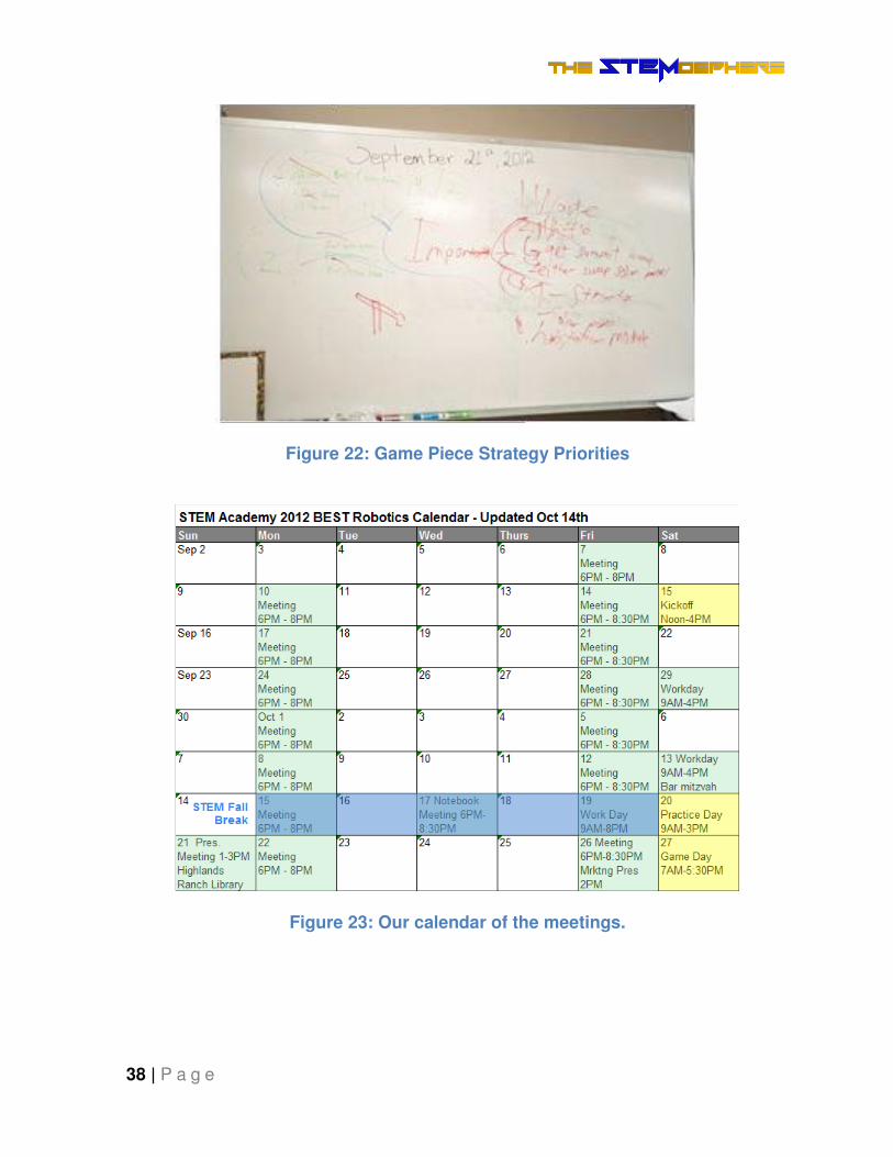
Figure 22: Game Piece Strategy Priorities
Figure 23: Our calendar of the meetings.

39 | P a g e
Date Agenda
21-Sep-12 Robot
Finish Understanding the Problem and Requirements
Continue Brainstorming and Concept Development (explore
possible design space)
Consider down selection criteria
Kit Inventory
Document activities and assign Action Items
BEST Award
Finish Understanding the Problem - Review Score
sheets/kickoff material
Continue Brainstorming (generating lists of ideas)
Document activities and assign Action Items
Marketing
Continue Brainstorming (generating lists of ideas)
Begin to consider down selection criteria
Start to mentor needs for marketing area
Document activities and assign Action Items
6-Oct-12 Robot
Game Field Completion
Electronics Team Layout - Running on a table (breadboard)
Claw prototype done (at least 1/2 grabber)
Ascension - working mounted to base
Shoulder motor mounting & operation
BEST Award
Presentation
Presentation time: 10:30 Primary 11:00 AM Secondary
Exhibit
Frame Design/Prototype
Spirit & Sportsmanship
Trace out last poster
Poster Glitter
T-shirt Designs Decided
Notebook
Note files we need
Appendix start
Marketing
Flyer
8-Oct-12 Robot
Defensive Strategy (see George)
Remake spool
Shoulder joint integration test

40 | P a g e
Finish grabber prototype
BEST Award
Notebook
Robert programming and math input doc
George take over strategy doc
Appendix/Reference
Research paper
Exhibit
Final materials list BOM (bill of materials)
Marketing
Letter to DJ
12-Oct-12 Robot
PE Team - Make initial SW build (Hopefully)
Attach new winch
Work on claw
Complete shoulder joint
BEST Award
Notebook
Edit programming document
Write and edit outreach and marketing document
Write preliminary design document
Start research paper
Start assembling appendix
Continue adding references to the appendix wherever
appropriate and possible
Exhibit
FINALIZE materials list
Buy materials
If we have materials, start building
15-Oct-12 Robot
Get the grabber working
Test picking up bottles
Get the extension joint working
Test length of reach
Finish the shoulder joint
BEST Award
Notebook
Finalize appendix
Finalize design document
Put together meeting minutes
Exhibit
Continue building the exhibit structure

41 | P a g e
Figure 24: Meeting Notes
Figure 25: An example of the coding that was used on the robot.
Begin assembling decorations
Continue working on posters
Continue working on the power point presentation
Marketing
Goddard Pre-School Activity
Ben Franklin Presentation

42 | P a g e
Figure 26: An example of a STEMosphere team member practicing proper safety practices. He is using safety glasses and following our other rules when it
comes to using the Drill Press.
Figure 27: Leaders are shown under the Lead Column, and were chosen based on their skill set. Teams that do not have a designated Lead have responsibility
shared by the members of that team. Dark blue squares with a P on the chart indicate a primary role, and light blue squares with an S on the chart indicate a
secondary role.

43 | P a g e
Figure28: Regional Claw Structure Drawing
-