teaching undergraduate introductory course to mechatronics … · teaching undergraduate...
TRANSCRIPT

Paper ID #7659
Teaching Undergraduate Introductory Course to Mechatronics in the Me-chanical Engineering Curriculum Using Arduino
Dr. Jose Antonio Riofrio, Western New England University
Jose A Riofrıo received his B.S. in Engineering Physics from Elizabethtown College in 2003, and hisM.S. and Ph.D. in Mechanical Engineering from Vanderbilt University in 2005 and 2008, respectively. AtVanderbilt, Jose focused his research in controls, mechatronics and mechanical design. After obtaininghis Ph.D., Jose worked in the Fluid Power industry designing servo-pneumatic control systems for variousmotion-control applications, such as packaging, automation, and animatronics. In the fall of 2011, Josebecame an assistant professor of Mechanical Engineering at Western New England University, where henow teaches various courses in solid mechanics and mechatronics.
Dr. Steven G Northrup, Western New England University
Professor Steve Northrup earned a BSEE from the University of Michigan and an MSEE and Ph.D. fromVanderbilt University. He worked in the defense industry in White Sands, NM and in the automotive elec-tronics industry for several years designing hardware and software for vehicle control systems. He teachescircuits and embedded controls classes at Western New England University in Springfield, MA. His re-search interests are in the mechatronics & robotics and in low cost medical applications for developingcountries.
c©American Society for Engineering Education, 2013
Page 23.1154.1

Teaching Undergraduate Introductory Course to Mechatronics in the Mechanical Engineering Curriculum Using Arduino
Abstract
This paper shares the author’s experience in introducing the broad field of Mechatronics to junior-level Mechanical Engineering students via a single non-elective course (“Introduction to Mechatronics”). Mechatronics is an increasingly popular, multidisciplinary field of engineering which combines mechanics, electronics, computer science and control systems. This synergistic approach to solving engineering problems is extremely valuable in the workplace, and therefore graduates and professionals with mechatronics-based skillsets are highly sought-after by engineering employers. Since all of the sub-areas that make up this field are relatively advanced (with respect to the typical undergraduate curriculum), Mechatronics is typically taught at the graduate level, and covered over a series of courses. Moreover, specific curricula vary among institutions, depending on the specific strengths of their faculty. Constructing an undergraduate-level introductory course therefore poses a clear challenge in selecting the appropriate content, methodology, and course structure. There are a few relatively well-known textbooks which aim to facilitate this instruction; however, due to the broadness and diversity of the field, these attempt to cover too many different topics and are therefore most useful as references, and not as course outlines.
In this paper, a project-based hands-on approach for teaching this course is presented. Since it is taught only to Mechanical Engineering students, the electronics, controls and computer science elements of Mechatronics at large are simplified by the use of the Arduino microcontroller, which is a popular device amongst non-technical hobbyists and artists, and is therefore a perfect gateway for students to gain understanding and appreciation for this type of electro-mechanical integration. Most of the academic rigor is placed in the mechanical portion, mostly pertaining to dynamics and kinematics, and in the context of an ongoing group project. Weekly Arduino programming assignments involve visual and mechanical elements such as LEDs, motors, solenoids, and various analog and digital sensors. This paper explains this approach and methodology in detail and outlines the benefits and difficulties encountered throughout. A contrast with the previous year’s more traditional approach (non-Arduino) is also offered. Overall, the students’ response and engagement level are highly encouraging and suggest that this approach can generate strong interest in the students to study Mechatronics at a higher level.
Introduction
Mechatronics, a relatively new term – and field of study – deals with the set of practical intersections between mechanics, electronics, computer science, and control theory. More specifically, it focuses on engineering problem-solving via an integrated system approach rather
Page 23.1154.2

than a sequential treatment by each isolated sub-field. Figure 1 shows one of many similar Venn diagrams which are commonly used to graphically represent the span of Mechatronics.
Figure 1: Typical Mechatronics composition diagram1
The instruction of Mechatronics at the university level has seen a dramatic increase in the last decade or so, and this rise is expected to continue as integrated technologies continue to thrive in the marketplace. A thorough justification for the need of education in Mechatronics has been extensively formulated and is beyond the scope of this paper.2,3,4,5
While in its most complete form Mechatronics contains elements from each of its defined constituents, in reality different university curricula in Mechatronics will tend to focus on specific subsets based on the strengths and background of the faculty involved. Typically, Mechatronics concentrations can belong to either Electrical or Mechanical Engineering departments, depending on the institution. It also varies as to whether it is found in undergraduate or graduate programs. This paper does not seek to provide a thorough survey or analysis on curriculum shaping, but such can be found in other relevant work.2,6,7,8
The work hereby presented specifically addresses the instruction of a single, non-elective, junior-level undergraduate introductory course to Mechatronics in the Mechanical Engineering program at Western New England University (WNE). WNE does not currently have a Mechatronics program for undergraduates (there are plans to start one in the near future), but it does offer a master’s-level concentration. That said, the course addressed in this paper is not a pre-requisite for this concentration.
Prior to this course, the students have had standard freshman- and sophomore-level courses in the ME curriculum such as Statics, Dynamics, Calculus 1 through 3, Differential Equations, and basic Circuit Analysis. They are also familiar with CAD and some basic computer programming learned in the context of a freshman-level MATLAB course which does not offer
Page 23.1154.3

any exposure to C/C++. It must also be kept in mind that these students have had no exposure to controls, measurement, instrumentation, modeling, or system dynamics. Furthermore, since this is a stand-alone course and not part of a larger Mechatronics concentration, there is a distinct challenge in how to best select the content and method of delivery, given the very large scope and number of topics associated with Mechatronics as a whole. Since the background of the target students lies largely on the “Mechanics” pillar, it is natural for these students to feel intimidated by electronics and computer science. The approach presented is rooted on this fact and aims to start in the comfort zone of Mechanics and familiarize students with the potential of what can be achieved by becoming proficient in the other 3. In addition, in order to make a lasting impact on the student with this stand-alone introductory course, this approach seeks to provide meaningful hands-on experiences to complement the relatively shorter lecture sessions. Several previous works have shown that Mechatronics-related courses are most effective when taught within a project-based, hands-on environment.5,9,10,11
Approach
This course is primarily structured around a comprehensive multi-stage design group project, which ties together most of the concepts and lab activities covered throughout. As a precursor to the project, several individual homework and lab assignments were given covering relevant topics such as advanced CAD modeling and design-for-manufacturability, micro-controller basics, sensors, actuators, and applied electronics. These assignments were mostly experimental in nature, and often required some kind of simple demonstration by the students as part of the required submission. At the beginning of the semester, each student was given a kit with various components to be used for these assignments as well as the final project (a list of these components is provided in the next section). In general, the lectures were kept short and light so that greater emphasis could be placed on demonstrations and hands-on activities. This greatly increased the students’ level of involvement and enthusiasm compared to the previous year, when a more lecture-based approach was taken.
Due to the students’ largely insufficient background in electronics and computer architecture and programming, this course is centered on the Arduino Uno as the main experimental platform. The Arduino Uno is in essence a break-out board for the Atmel ATmega328, which is a relatively simple and low-power micro-controller. While a more common approach is to utilize a micro-controller chip directly (such as an Atmel AVR or a Microchip PIC) and instrument it as part of the course agenda12,13, in this class it was chosen to bypass chip instrumentation in order to focus more on its functionality. Obviously this level of chip instrumentation and computer architecture is an essential part of Mechatronics at large, both from the standpoint of design flexibility and access to state-of-the-art computational capability; however, in the interest of providing a big-picture introduction which builds on relevant existing ME skills, this omission is considered worthwhile. As a break-out board, Arduino provides 14 I/O digital pins and 6 10-bit analog input pins. Six of the digital pins can be used as pulse-width modulated (PWM) outputs,
Page 23.1154.4

which operate at a fixed 490-Hz frequency and whose pulse-widths have 8-bit resolution (total of 256 discrete widths). An image of the Arduino Uno is shown in Figure 2. All the programing is done within Arduino’s open-source integrated development environment (IDE), which comes with a C/C++ library. Due to its popularity, several resources and open-source libraries exist which make programing a relatively easy endeavor for those with little or no programming backgrounds. Each student was required to purchase an Arduino Uno, among other components, at the beginning of the semester.
Figure 2: Arduino Uno.
Course Setup
This 15-week course met twice weekly for 80-minute sessions, and the class size was 26 students. Typically, one session would focus on lecture, discussion and/or demonstrations, while the other would focus on a specific hands-on activity. These two weekly sessions were for the most part treated separately: the lecture portion focused on “standard” mechatronics topics (such as sensors and measurement, actuation systems, basic controls, power equivalences among electric and mechanical domains), while the hands-on portion covered mostly topics pertaining to Arduino-programming and component integration, in large part developing a knowledge-base towards the final project. The project was assigned relatively early in the semester and became the main focus of the course. A conceptual final exam was given at the end which covered material both from the lectures and the hand-on activities. The grade distribution of the course – 40% homework and labs, 45% project and 15% final exam – reflect the importance of hands-on learning as a key approach to this subject.
A list of components purchased by each student at the beginning of the semester is shown in Table 1. It should be noted that a textbook was not required, and the lecture content came from various academic and non-academic sources. A basic solderless breadboard is used for all circuit making; LEDs are used for various Arduino exercises; a standard servo motor and a solenoid are used for lab activities pertaining to electromechanical actuators (the solenoid is the centerpiece
Page 23.1154.5

for this year’s project which will be discussed later); a knobbed potentiometer is used to create various analog input signals; a slotted optical photo-interrupter is used for demonstrating digital position sensing (also playing a key role in the project); a low-threshold-voltage N-Channel MOSFET transistor, specifically selected to work with Arduino’s 5V output capability, is used for driving the solenoid; and finally, a battery holder is used to power the Arduino for untethered demonstrations. Other miscellaneous electronic components (resistors, capacitors, jumper wires, etc.) were provided to the students as needed.
Table 1: List of components purchased by each student.
Item Vendor Part # Cost Arduino Uno Sparkfun DEV-11224 $ 29.95 USB Cable for Arduino Sparkfun CAB-00512 $ 3.95 Solderless Breadboard Parallax 700-00078 $ 4.99 LED kit (20-pack) Sparkfun COM-10049 $ 2.95 Knobbed potentiometer Sparkfun COM-09288 $ 0.95 Standard Servo Motor Parallax 900-00005 $ 12.99 Pull-type solenoid AllElectronics SOL-138 $ 2.50 Optical Photo-interrupter DigiKey OPB815L $ 2.56 N-Channel MOSFET Sparkfun RFP30N06LE $ 0.95 4xAA Battery Holder Sparkfun PRT-09835 $ 2.49
Total $ 64.28
Project
This year’s group project was for students to design, build, instrument and operate a solenoid engine, applying concepts learned and utilizing components obtained throughout the course, as well as taking advantage of various manufacturing capabilities within the College of Engineering at Western New England University – namely, a fully-equipped and staffed machine shop as well as 2 rapid prototype machines. A solenoid engine is a relatively simple device: a flywheel is kinematically connected to a solenoid via a series of linkages, and kept in motion by energizing the solenoid at a very precise instance within the rotation of the flywheel. Figure 3 shows a very basic representation of this type of engine.
Page 23.1154.6
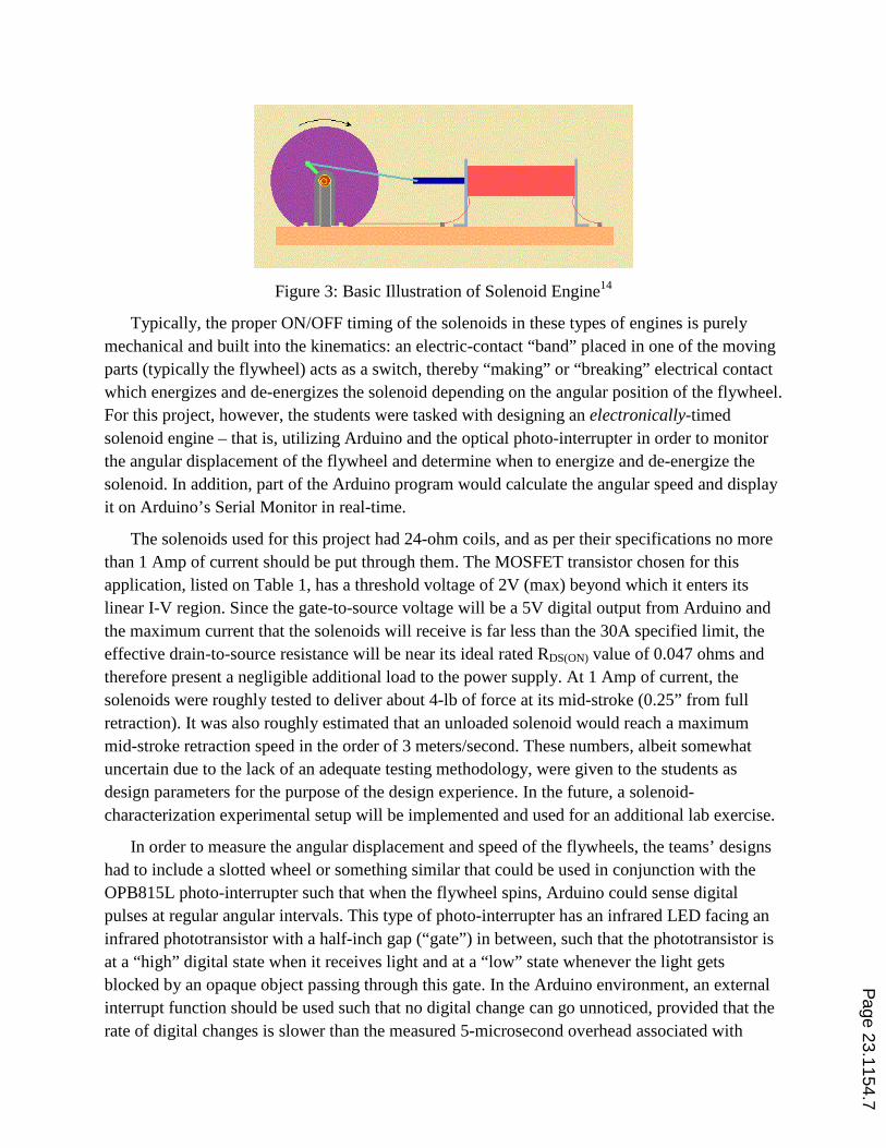
Figure 3: Basic Illustration of Solenoid Engine14
Typically, the proper ON/OFF timing of the solenoids in these types of engines is purely mechanical and built into the kinematics: an electric-contact “band” placed in one of the moving parts (typically the flywheel) acts as a switch, thereby “making” or “breaking” electrical contact which energizes and de-energizes the solenoid depending on the angular position of the flywheel. For this project, however, the students were tasked with designing an electronically-timed solenoid engine – that is, utilizing Arduino and the optical photo-interrupter in order to monitor the angular displacement of the flywheel and determine when to energize and de-energize the solenoid. In addition, part of the Arduino program would calculate the angular speed and display it on Arduino’s Serial Monitor in real-time.
The solenoids used for this project had 24-ohm coils, and as per their specifications no more than 1 Amp of current should be put through them. The MOSFET transistor chosen for this application, listed on Table 1, has a threshold voltage of 2V (max) beyond which it enters its linear I-V region. Since the gate-to-source voltage will be a 5V digital output from Arduino and the maximum current that the solenoids will receive is far less than the 30A specified limit, the effective drain-to-source resistance will be near its ideal rated RDS(ON) value of 0.047 ohms and therefore present a negligible additional load to the power supply. At 1 Amp of current, the solenoids were roughly tested to deliver about 4-lb of force at its mid-stroke (0.25” from full retraction). It was also roughly estimated that an unloaded solenoid would reach a maximum mid-stroke retraction speed in the order of 3 meters/second. These numbers, albeit somewhat uncertain due to the lack of an adequate testing methodology, were given to the students as design parameters for the purpose of the design experience. In the future, a solenoid-characterization experimental setup will be implemented and used for an additional lab exercise.
In order to measure the angular displacement and speed of the flywheels, the teams’ designs had to include a slotted wheel or something similar that could be used in conjunction with the OPB815L photo-interrupter such that when the flywheel spins, Arduino could sense digital pulses at regular angular intervals. This type of photo-interrupter has an infrared LED facing an infrared phototransistor with a half-inch gap (“gate”) in between, such that the phototransistor is at a “high” digital state when it receives light and at a “low” state whenever the light gets blocked by an opaque object passing through this gate. In the Arduino environment, an external interrupt function should be used such that no digital change can go unnoticed, provided that the rate of digital changes is slower than the measured 5-microsecond overhead associated with
Page 23.1154.7

entering and leaving said function. An interrupt function can be triggered with a signal rising (switch from “low” to “high”), falling (switch from “high” to “low”) or simply changing in either direction. Arduino recognizes a “low” to “high” transition whenever the signal rises past 3V, and a “high” to “low” transition whenever it falls below 2V. Assuming a “change”-type trigger, the students were instructed to include no more than 25 windows (50 changes) per revolution. Since the crank arm in each engine is constrained to the 0.25-inch (6.35-mm) mid-stroke length of the solenoids, the estimated maximum tangential speed of 3 meters/sec at this crank point corresponds to roughly 75 revolutions per second of the flywheel (4500 rpm). Thus, 50 digital changes per revolution at 75 revolutions per second will equate to just over 250-microsecond intervals between changes. Note that this is almost two orders of magnitude slower than the interrupt function overhead, and is therefore assumed to be a good starting point. Having multiple angular displacement markers, as opposed to simply placing a few at precise “timing” angular positions, allows for electronically advancing or retarding the timing, which the students can manipulate in the attempt to produce the fastest engine.
For this project, the students were grouped in teams of 3 or 4 and were allowed to use up to 3 solenoids per engine. In addition to being able to utilize components acquired at the beginning of the course (Table 1), each team was allowed to spend a maximum of $50 for miscellaneous hardware (i.e., bearings, shoulder bolts, pins). These would be paid for by the teams’ own members, and would require approval of the instructor, as well as cost documentation. The purchasing of additional solenoids, actuators or power supplies was not allowed. For all fabrication, the teams could request either metal machining or rapid prototyping (the latter constrained to $50 worth of material, which costs roughly $0.25 per cubic centimeter, and would be paid for by the ME department).
The timeline of the project was structured such that the students could focus mainly on the mechanical portion of the project during the first two-thirds, and on the electro-mechanical integration at the end. The idea is to get them to build momentum on the parts of the project that they are most comfortable with (kinematics, design, CAD and fabrication) while learning the electronic building blocks during the weekly Arduino hands-on sessions through various individual assignments (sensors, motors and actuators, interrupt routines and programming). By the time their engines are assembled, they have the necessary knowledge to fully instrument them and get them to run. The project was assigned on week #4, and the timeline of deliverables for the project was laid out as follows:
1) Kinematic Analysis, CAD Drawings and Project Proposal (due on week #7): Students had to present the full assembly of their proposed team’s design, providing detailed 3-view dimensional drawings for each individual part that needs manufacturing. The desired manufacturing process and desired material had to be specified for each part. A short report (2-4 pages) would explain the proposed device and rationale, and contain a bill-of-materials table listing the amount of rapid prototype material required for each part and any additional parts to be purchased. In addition, a full kinematic analysis was to
Page 23.1154.8

be included with the report, showing hand-written calculations and projected maximum speeds. One week before this proposal was due, there was a session of short oral presentations where each team showed the CAD assemblies of their proposed engines and received advice and critiques from the instructor, their classmates and our full-time machinist, who attended the session. This portion of the project aimed to emulate a company-level approach to product design.
2) Mechanical Construction of Engine (due on week #10): Teams had to show a fully-built mechanical device, with all parts assembled together and the flywheel mounted with all the kinematic linkages in place, including the solenoids and the photo-gate. The main reason for imposing this deadline is to ensure that the students can fully focus on the electronics from here on out.
3) Final Demonstration and Competition (due on week #15): Teams had to demonstrate a fully self-contained and operational engine. The instructor would provide a 20V power supply, which could deliver almost 1 Amp of current to the 24-ohm solenoid coils. All engines had to include two lead wires, clearly labeled “20 V” and “GND”. When demonstrating their engines running, each team would have to show Arduino’s Serial Monitor displaying angular speed (in revolutions per minute). The true angular speed was measured by the instructor with the help of a hand-held digital tachometer, which would be compared to each team’s display. This event was run as a competition, where bonus points were awarded to the team with the fastest engine, highest speed-to-weight ratio, highest rotational kinetic energy of the flywheel, and finally overall best design (this last one vote by the students themselves – but they were not allowed to vote on their own).
Project Results
Overall the project was highly successful, and all 7 teams were able to produce running engines. 4 teams produced 3-solenoid engines, while the other 3 opted for simpler 2-solenoid designs. The students showed a remarkable level of enthusiasm and all designs were uniquely different. There was also a broad spectrum of manufacturing approaches, from all machined metal, to some combination of machined parts and rapid prototyped parts, to all rapid-prototyped. Although all the machining is typically done exclusively by the staffed machinist, several students took the initiative to learn from him and perform some of their own (supervised) machining.
The fastest engine (and the competition winner) was clocked at an impressive 2600 rpm. This engine is shown in Figure 4. Most of the components were machined out of aluminum, and in the case of this team, all the machining was done purely by the students. The flywheel and the bracket holding the photo-interrupter were rapid prototyped, and the flywheel spray-painted in order to make it fully opaque. This team opted for a simple 3-window flywheel, which emulated the operation of a traditional mechanically-timed solenoid engine. The engines from the teams scoring 2nd and 3rd place are shown in Figures 5 and 6, respectively. The team in 2nd place,
Page 23.1154.9
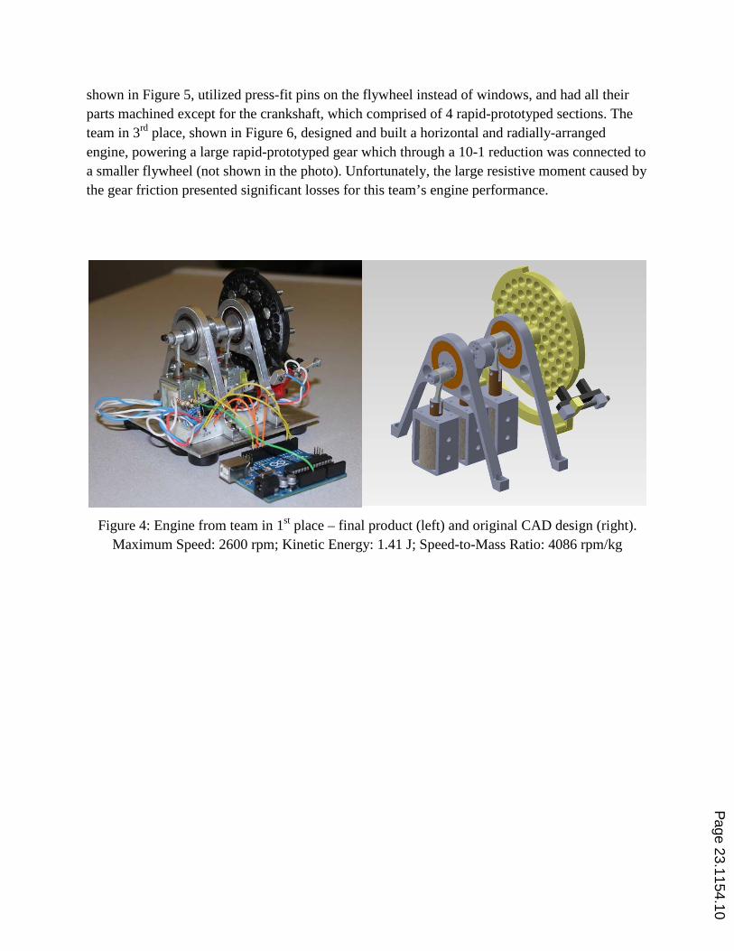
shown in Figure 5, utilized press-fit pins on the flywheel instead of windows, and had all their parts machined except for the crankshaft, which comprised of 4 rapid-prototyped sections. The team in 3rd place, shown in Figure 6, designed and built a horizontal and radially-arranged engine, powering a large rapid-prototyped gear which through a 10-1 reduction was connected to a smaller flywheel (not shown in the photo). Unfortunately, the large resistive moment caused by the gear friction presented significant losses for this team’s engine performance.
Figure 4: Engine from team in 1st place – final product (left) and original CAD design (right).
Maximum Speed: 2600 rpm; Kinetic Energy: 1.41 J; Speed-to-Mass Ratio: 4086 rpm/kg
Page 23.1154.10

Figure 5: Engine from team in 2nd place – final product (left) and original CAD design (right).
Maximum Speed: 2400 rpm; Kinetic Energy: 1.46 J; Speed-to-Mass Ratio: 4400 rpm/kg
Figure 6: Engine from team in 3rd place.
Maximum Speed: 634 rpm; Kinetic Energy: 1.88 J; Speed-to-Mass Ratio: 215 rpm/kg
Student Feedback
At the end of the semester, the students filled out a standard course evaluation survey delivered by the College of Engineering at WNE. The survey prompts each student to rate a
Page 23.1154.11
range of statements about the quality of the course, the professor, and the resources. The feedback received was highly positive in all categories, especially in those pertaining to the main objective of hands-on and project-based learning. The survey also asks a few additional questions about what was liked and disliked about the course, what can be done to improve the course, what worked best in assisting the student’s learning, and any additional comments the student may have. Throughout these questions, several students wrote “awesome”, “fun”, and/or “favorite class”. Under the question “what did you like about this course?”, 18 out of 26 students explicitly wrote either “hands-on” or “project”. Some examples of additional comments are:
“Everything we did was useful to our projects and homework, they reflected what we needed to know.”
“fun class, enjoyed going to class; it is exciting to build an engine and be able to put our time and effort into an eventful project”
“The project was a great way to learn the material”
“hands-on learning; projects & homework challenging but fun”
Under the question “what did you not like about this course?”, 2 students wrote “the lectures”, 3 students wrote “programming” and one student wrote “the main grade is based on group work”. The remaining students either wrote “nothing”, “N/A”, or left it blank. Some specific suggestions for future improvement were to start the project earlier (3 students) and to improve the lecture/lab structure of the course (4 students).
During the previous year, this course was taught in a more lecture-based fashion, where traditional introductory Mechatronics topics were covered in a standard classroom environment. As is typical with most ME courses taught at WNE, there was a group project toward the end of the course, where each team had to create a simple closed-loop control system by selecting and integrating a sensor and actuator in a customized mechanical arrangement. The open-endedness of this project, coupled with its relatively short time-span (approximately one month) presented several challenges both for the instructor and for the students. In contrast, this new approach, which integrates the project with the lectures, offers the following key improvements: 1) It keeps the lectures shorter and more on-point, 2) it standardizes the project and creates a sense of competition amongst the groups, and 3) it allows for a much longer project time-span, which traded stress for enjoyment. The improvements are evident from the student evaluations: Figure 7 shows a comparison of student feedback between this year’s (2012) new Arduino-based hands-on approach and last year’s (2011) more lecture-based approach. Only the most relevant questions are shown, although there is an increase in average score in every single question on the survey. The rating breakdown is: 1=poor, 2=fair, 3=satisfactory, 4=good and 5=excellent. It should be pointed out that in 2011 the author covered 2 sections of this course, whereas in 2012 it was only 1 section. This explains the sample difference (46 vs. 26 students) in Figure 7. P
age 23.1154.12

Figure 7: Comparison of results of student evaluations between this year’s (2012) hands-on
approach and last year’s (2011) lecture-based approach.
Conclusions
A hands-on, project-based approach to teaching introductory Mechatronics to undergraduate students in a Mechanical Engineering curriculum was shown. This course is mainly structured around a multi-stage team project which is mostly mechanical in nature but requires enough electro-mechanical integration to effectively introduce the scope, reach and potential of Mechatronics. Every student obtained their own Arduino Uno microcontroller and a set of basic electro-mechanical components, which greatly facilitated hands-on learning at an individual level. A particular emphasis was placed on a group design process similar to that in a small-company, where each group is responsible for manufacturable design, fabrication, instrumentation, and experimental validation of a functional mechatronic system. The success of this approach is manifested by the quality of project submissions and by the highly positive results in the student feedback survey. The results from this survey also show great improvements over the previous year, when a more lecture-based teaching approach was used.
Page 23.1154.13

Bibliography
1. Alinex, Inc. n.p. n.d. Web. 14 Jan. 2013. www.alignex.com 2. Bradley, D., “What is Mechatronics and Why Teach it?”, International Journal of Electrical
Engineering Education, v 41, n 4, p 275-291, October 2004. 3. Habib, M.K., “Mechatronics Engineering: The Evolution, the Needs and the Challenges,”
Proceedings for the 32nd Annual Conference on IEEE Industrial Electronics, November 6-10, 2006.
4. Kyura, N., Oho, H., “Mechatronics: an Industrial Perspective,” IEEE/ASME Transactions on Mechatronics, v 1, n 1, p 10-15, March 1996.
5. Wen-Long Yao, A., Sun, J.H., Fung, R.F., Chen, M.C., “Development of an Initial Mechatronics Course Based on Reverse Engineering and Project-Based Learning in Taiwan,” Proceedings for the 117th Annual ASEE Conference and Exposition, Louisville, KY, June 20-23, 2010.
6. Currier, P., Goff, R., Terpenny, J., “A Proposed Learner-Centered Mechatronics Engineering Instructional Program”, Proceedings for the 117th Annual ASEE Conference and Exposition, Louisville, KY, June 20-23, 2010.
7. Smaili, A., “A Model for Integrating Mechatronics into Mechanical Engineering Education,” 109th Annual ASEE Conference and Exposition, Montreal, Canada, June 16-19, 2002.
8. Ebert-Uphoff, I., Gardner, J.F., Murray, W.R., Perez, R., “Preparing for the Next Century: the State of Mechatronics Education,” IEEE/ASME Transactions on Mechatronics, v 5, n 2, p 226-227, June 2000.
9. Gurocak, H., “Mechatronics Course With a Two-Tiered Project Approach”, Proceedings for the 114th Annual ASEE Conference and Exposition, Honolulu, HI, June 24-27, 2007.
10. Durfee, W.K., “Designing Smart Machines: Teaching Mechatronics to Mechanical Engineers Through a Project-Based, Creative Design Course,” Mechatronics, v 5, n 7, p 775-785, October 1995.
11. Shyr, W.J., “Teaching Mechatronics: An Innovative Group Project-Based Approach,” Computer Applications in Engineering Education, v 20, n 1, p 93-102, March 2012.
12. Alciatore, D.G., Histand, M.B., Introduction to Mechatronics and Measurement Systems, 3rd edition. McGraw-Hill, New York, NY, 2007.
13. Linde, E., Dolan, D., Batchelder, M., “Mechatronics for Multidisciplinary Teaming,” 110th Annual ASEE Conference and Exposition, Nashville, TN, June 22-25, 2003.
14. “My Single Solenoid Electric Engine.” Mad Teddy. n.p. 2002. Web. 14 Jan. 2013. www.madteddy.com
Page 23.1154.14